Screws, Fasteners, and the Design of Nonpermanent ... · rapidly than a singlerapidly than a...
155
Chapter 8 Screws, Fasteners, and the Design of Nonpermanent Joints Nonpermanent Joints 1
Transcript of Screws, Fasteners, and the Design of Nonpermanent ... · rapidly than a singlerapidly than a...
Chapter 8p
Screws, Fasteners, and the Design of Nonpermanent JointsNonpermanent Joints
1
Machine design—what is it?
Subset of Mechanical design…which is S b t f E i i d i hi h iSubset of Engineering design…which isSubset of Design….which isSubset of the topic of Problem SolvingSubset of the topic of Problem Solving
What is a machine? …a combination of resistant bodies arranged so that by their means the mechanical forces of nature can be compelled to do work accompanied by certain determinate motionsmotions.
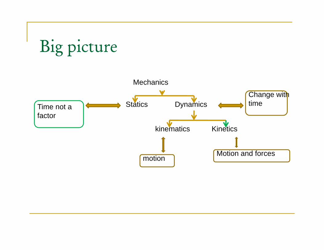
Big pictureBig picture
Mechanics
Statics DynamicsChange with timeTime not a
kinematics Kinetics
e o afactor
motionMotion and forces

The Design Process
R i d/d fi bl•Recognize need/define problem•Create a solution/designP d l/ t t / l ti•Prepare model/prototype/solution
•Test and evaluateC i t d i•Communicate design

Important to review the Important to review the fundamentals of….
•Statics•Dynamics•Materials/material properties•Mechanics of Materials•Design of Mechanical Systems 1•Design of Mechanical Systems 1•Dynamics of Machinery
Power Screws
Transmit angular motion to linear motionTransmit angular motion to linear motionTransmit large or produce large axial forceIt i l d i d t d b fIt is always desired to reduce number of screws
6
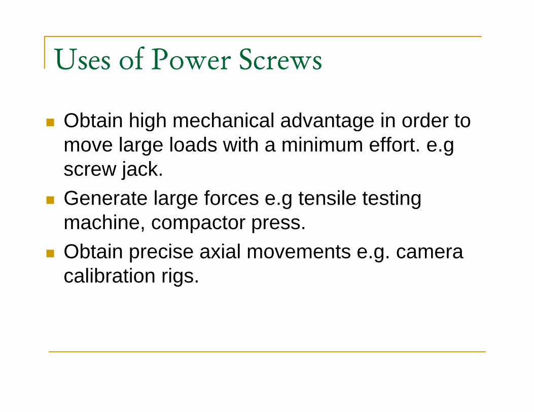
Uses of Power Screws
Obtain high mechanical advantage in order to g gmove large loads with a minimum effort. e.gscrew jack.Generate large forces e.g tensile testing machine, compactor press.p pObtain precise axial movements e.g. camera calibration rigs.g
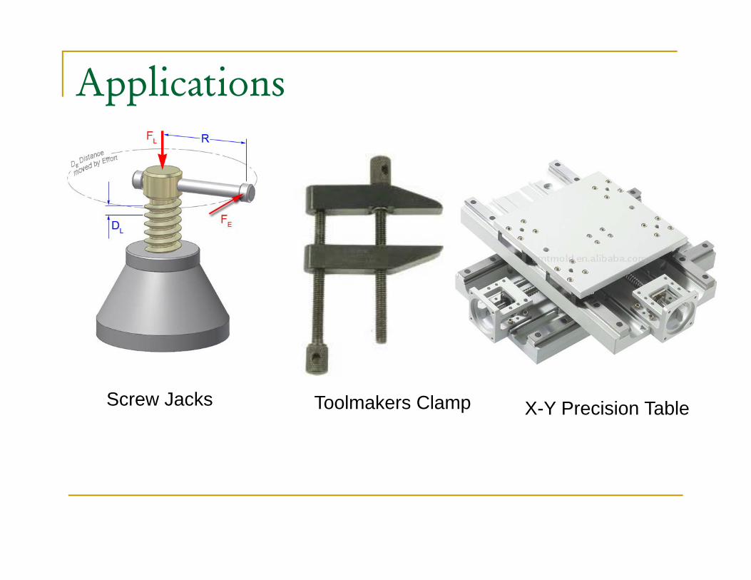
Applications
Screw
Screw Jacks Toolmakers ClampScrew Jacks Toolmakers Clamp X-Y Precision Table
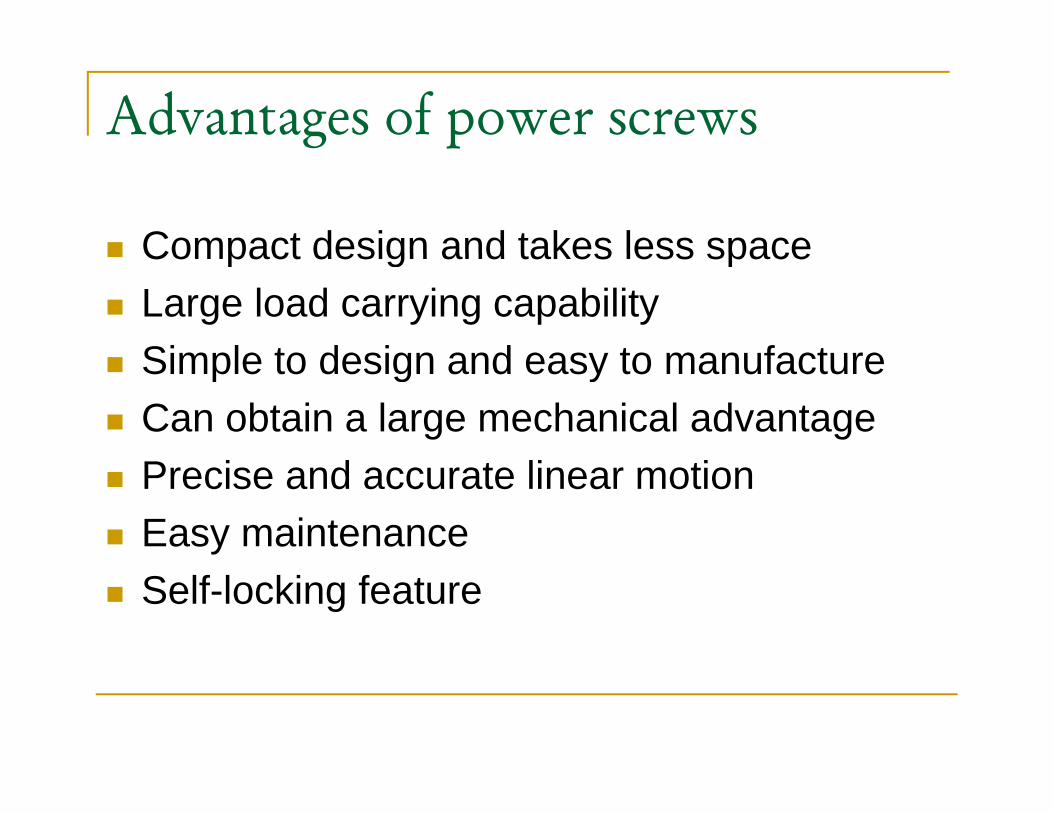
Advantages of power screws
Compact design and takes less spaceCompact design and takes less spaceLarge load carrying capabilitySimple to design and easy to manufactureSimple to design and easy to manufactureCan obtain a large mechanical advantagePrecise and accurate linear motionEasy maintenance Self-locking feature
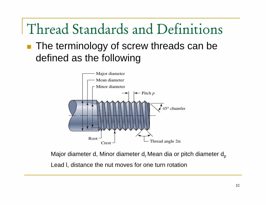
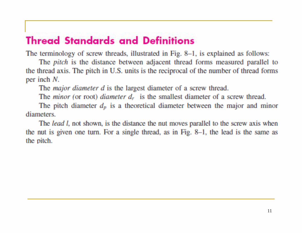
Thread Standards and Definitions The terminology of screw threads can be defined as the following
Major diameter d, Minor diameter dr Mean dia or pitch diameter dp
Lead l, distance the nut moves for one turn rotation
10
,
11
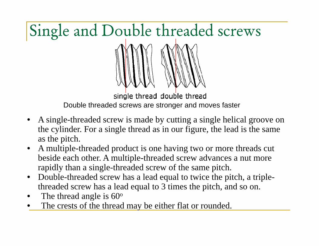
Single and Double threaded screws
Double threaded screws are stronger and moves fasteroub e eaded sc e s a e s o ge a d o es as e
• A single-threaded screw is made by cutting a single helical groove on the cylinder. For a single thread as in our figure, the lead is the same as the pitchas the pitch.
• A multiple-threaded product is one having two or more threads cut beside each other. A multiple-threaded screw advances a nut more rapidly than a single-threaded screw of the same pitch.rapidly than a single threaded screw of the same pitch.
• Double-threaded screw has a lead equal to twice the pitch, a triple-threaded screw has a lead equal to 3 times the pitch, and so on.
• The thread angle is 60og• The crests of the thread may be either flat or rounded.

Screw Designations
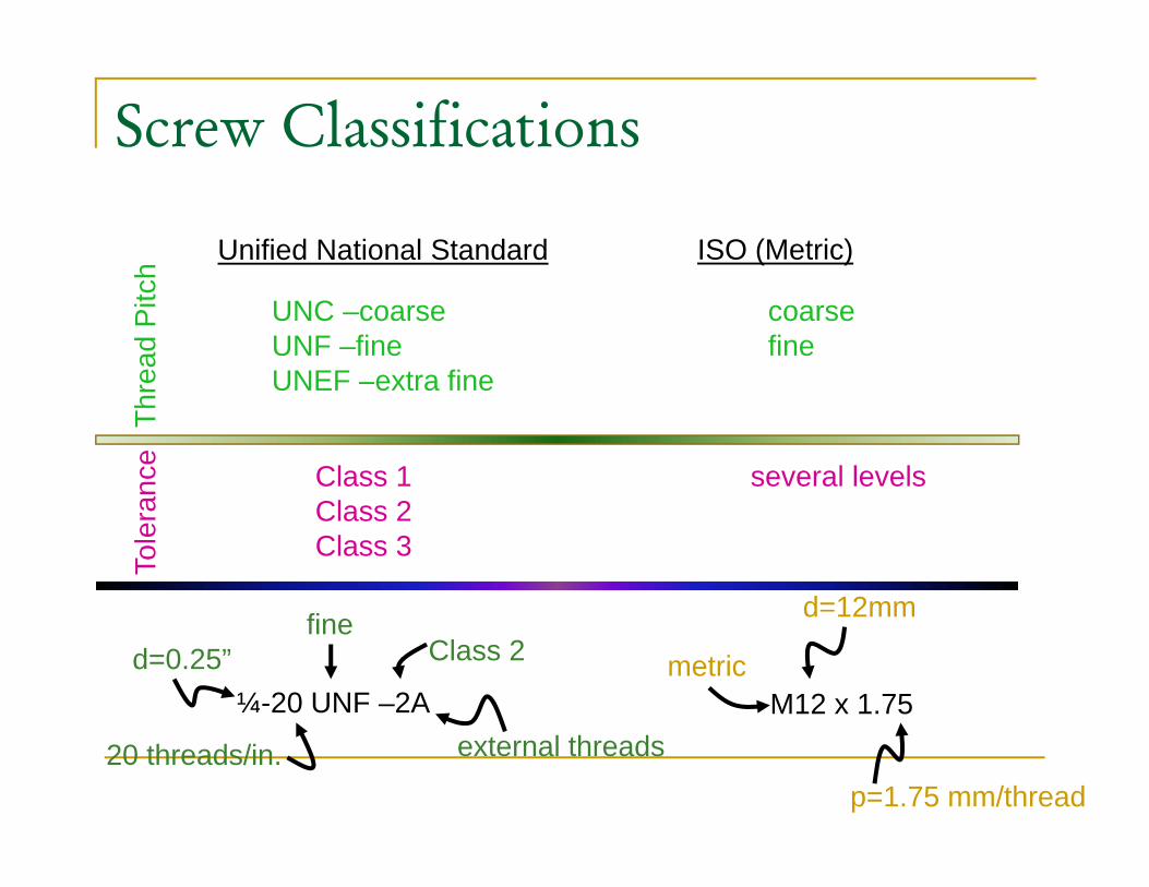
United National Standard UNSUnited National Standard UNSInternational Standard Organization ISO
UNC (Coarse thread): is the most common and recommended for ordinaryapplications, where the screw is threaded into a softer material. It is usedfor general assembly work.
UNF (Fine thread): is more resistant to loosening, because of its smaller( ) g,helix angle. Fine threads are widely employed in automotive, aircraft, andother applications where vibrations are likely to occur.
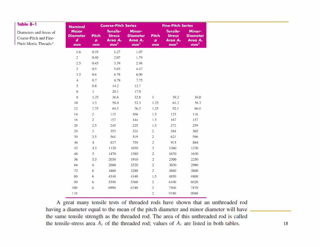
Many tensile tests of threaded rods have shown that an unthreaded rodhaving a diameter equal to the mean of the pitch diameter and minordiameter will have the same tensile strength as the threaded rod. The areagof this unthreaded rod is called the tensile-stress area At of the thread rod.
Metric threads are specified by writing the diameter and pitch inMetric threads are specified by writing the diameter and pitch inmillimeters, in that order, thus M12X1.75 is a thread having a nominalmajor diameter of 12mm and pitch of 1.75mm.
14
S D i tiScrew Designations
Class of screw, defines its fit, Class 1 fits have widest tolerances, Class 2 is the most commonly usedusedClass three for very precision applicationExample:1in-12 UNRF-2A-LH, A for Ext. Thread p ,and B for Internal, R root radiusMetric M10x1.5 10 diameter mm major diameter 1 5 pitchdiameter,1.5 pitch
Screw Classifications
Unified National Standard ISO (Metric)
hre
ad P
itch
UNC –coarseUNF –fineUNEF –extra fine
coarsefine
Thr UNEF extra fine
ance Class 1 several levels
d=12mm
Tole
ra Class 2Class 3
¼-20 UNF –2A
Class 2d=0.25”fine
M12 x 1.75metric
d 12mm
20 threads/in. external threads
p=1.75 mm/thread
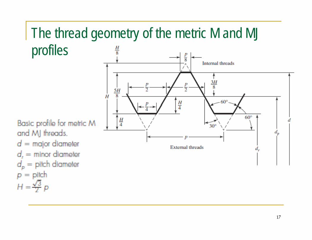
The thread geometry of the metric M and MJ profiles
17
18
19
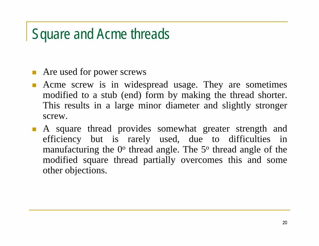
Square and Acme threads
Are used for power screwspAcme screw is in widespread usage. They are sometimesmodified to a stub (end) form by making the thread shorter.This results in a large minor diameter and slightly strongerThis results in a large minor diameter and slightly strongerscrew.A square thread provides somewhat greater strength andefficiency but is rarely used due to difficulties inefficiency but is rarely used, due to difficulties inmanufacturing the 0o thread angle. The 5o thread angle of themodified square thread partially overcomes this and someother objectionsother objections.
2020
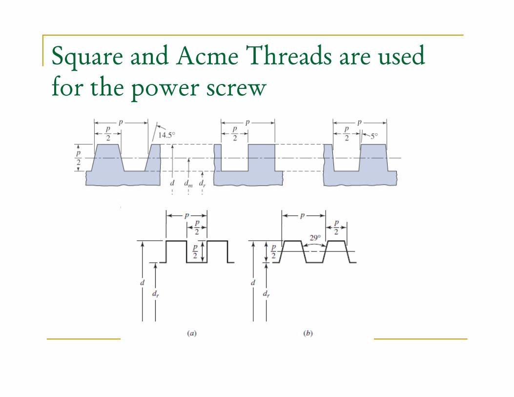
Square and Acme Threads are used for the power screw
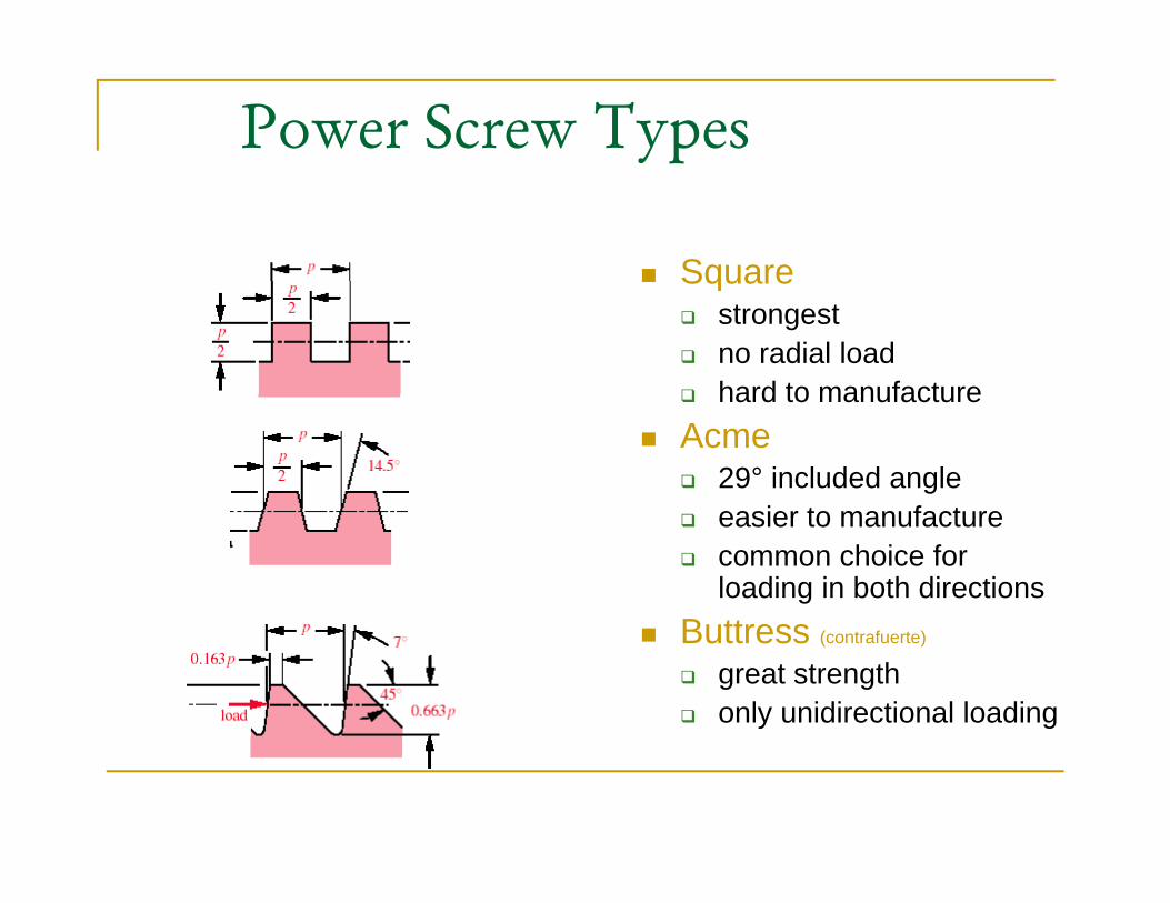
Power Screw Types
SquareSquarestrongestno radial loadhard to manufacturehard to manufacture
Acme29° included angle
i t f teasier to manufacturecommon choice for loading in both directions
B ttButtress (contrafuerte)
great strengthonly unidirectional loading
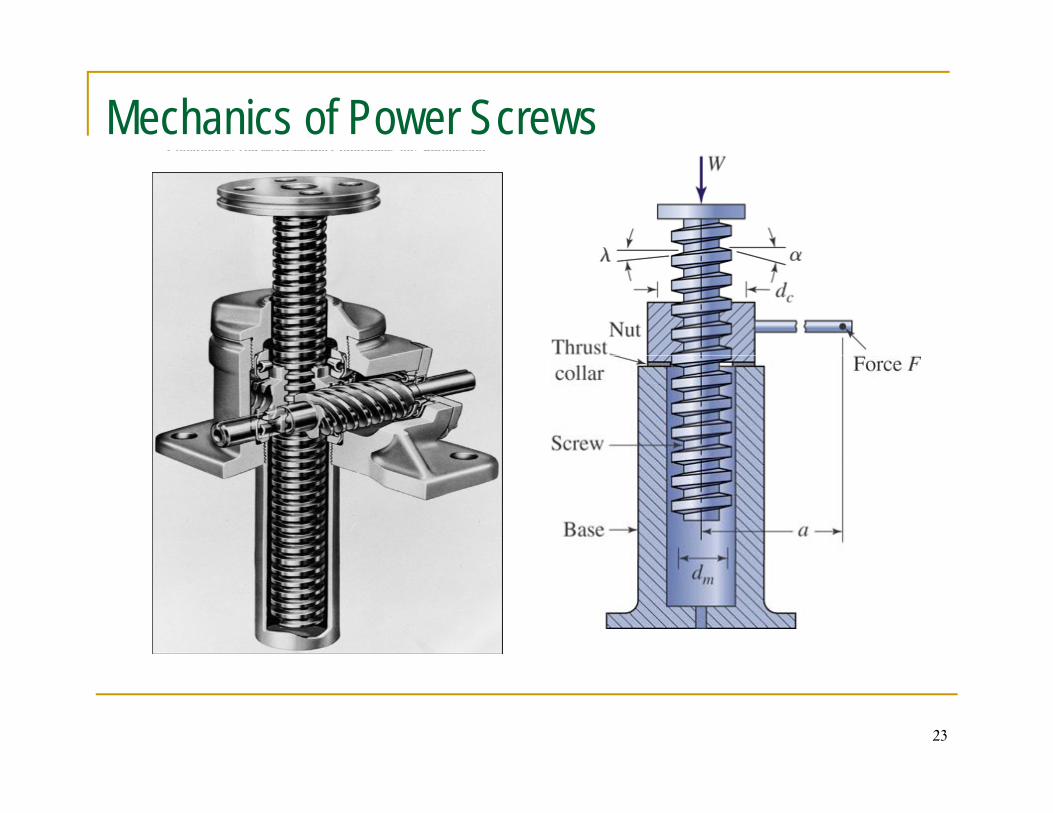
Mechanics of Power Screws
23
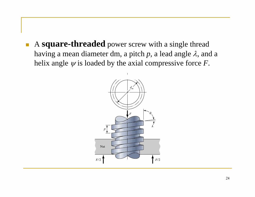
A square-threaded power screw with a single thread having a mean diameter dm, a pitch p, a lead angle λ, and a h li l i l d d b th i l i f Fhelix angle ψ is loaded by the axial compressive force F.
24
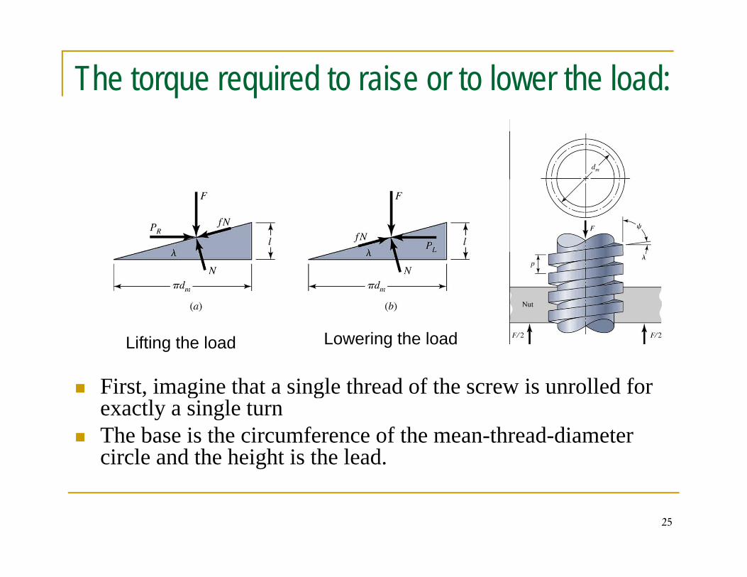
The torque required to raise or to lower the load:
First, imagine that a single thread of the screw is unrolled for
Lifting the load Lowering the load
g gexactly a single turnThe base is the circumference of the mean-thread-diameter circle and the height is the lead.
25
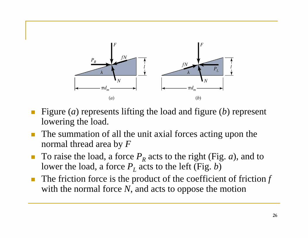
Figure (a) represents lifting the load and figure (b) represent lowering the load. The summation of all the unit axial forces acting upon theThe summation of all the unit axial forces acting upon the normal thread area by FTo raise the load, a force PR acts to the right (Fig. a), and to l th l d f P t t th l ft (Fi b)lower the load, a force PL acts to the left (Fig. b)The friction force is the product of the coefficient of friction f with the normal force N, and acts to oppose the motion
2626
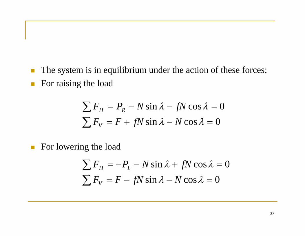
The system is in equilibrium under the action of these forces:y qFor raising the load
∑ 0i λλ fNNPF
∑∑
=−+=
=−−=
0cossin0cossin
λλλλ
NfNFFfNNPF
V
RH
For lowering the load
∑ + 0i λλ fNNPF
∑∑
=−−=
=+−−=
0cossin0cossin
λλλλ
NfNFFfNNPF
V
LH
27
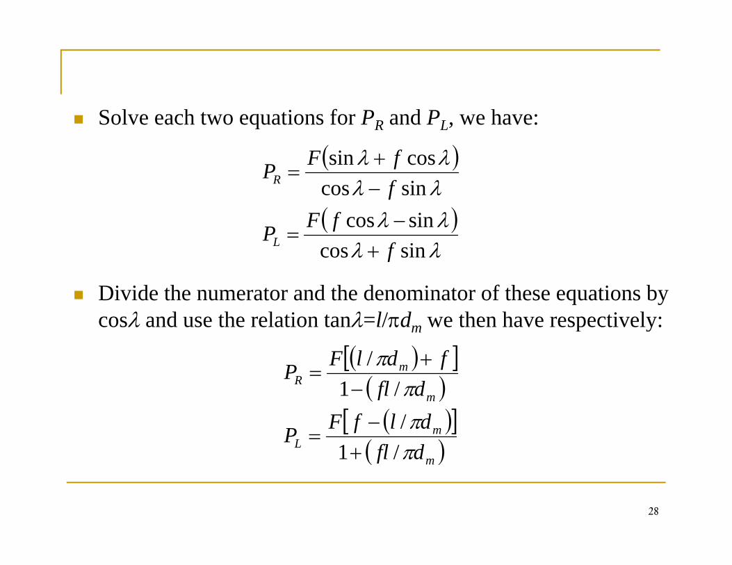
Solve each two equations for PR and PL, we have:
( )λλ cossin fFPR+
=
( )λλλλλλ
isincos
sincos
ffFP
fP
L
R
+−
=
−
Divide the numerator and the denominator of these equations by cosλ and use the relation tanλ=l/πd we then have respectively:
λλ sincos f+
cosλ and use the relation tanλ=l/πdm we then have respectively:
( )[ ]( )
mR dfl
fdlFPπ
π/1
/ += ( )
( )[ ]( )m
mL
m
dfldlfFP
dfl
πππ
/1/
/1
+−
=
−
28
( )mf
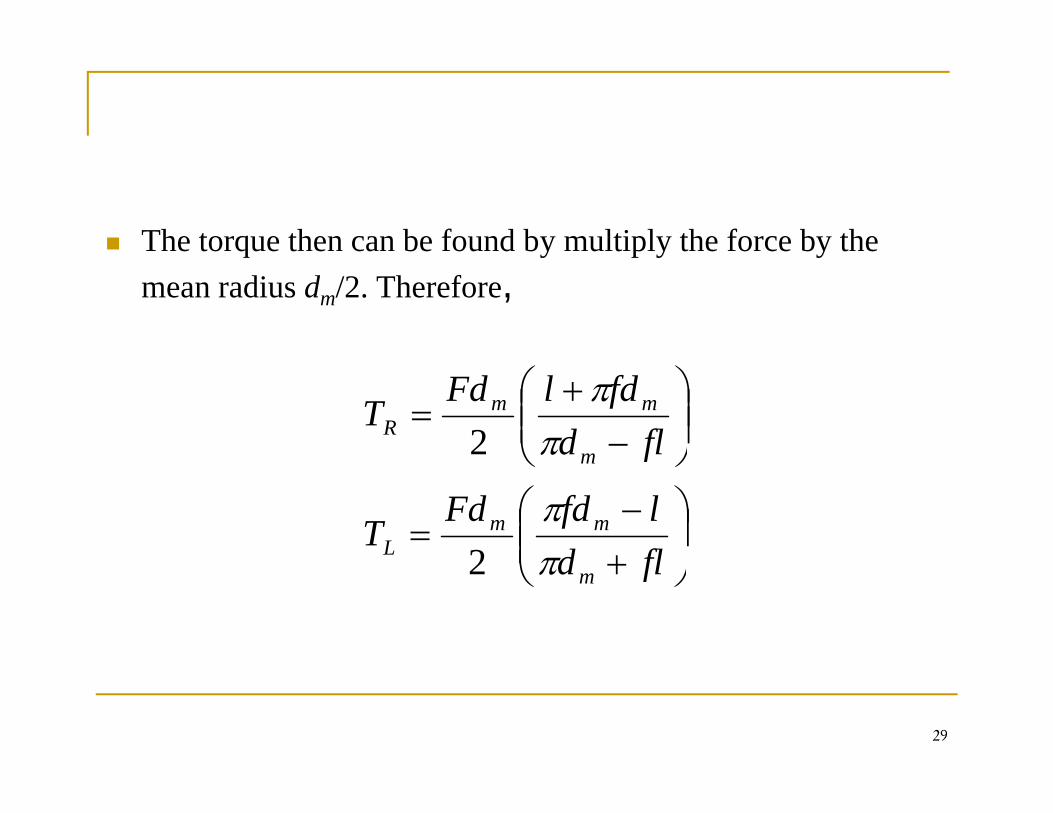
The torque then can be found by multiply the force by the q y p y ymean radius dm/2. Therefore,
⎟⎟⎠
⎞⎜⎜⎝
⎛−
+=
fldfdlFd
Tm
mmR π
π2
⎟⎠
⎞⎜⎜⎝
⎛+−
=
⎠⎝
fldlfdFd
T
f
mmL
m
ππ
2 ⎠⎜⎝ + fldmπ2
29
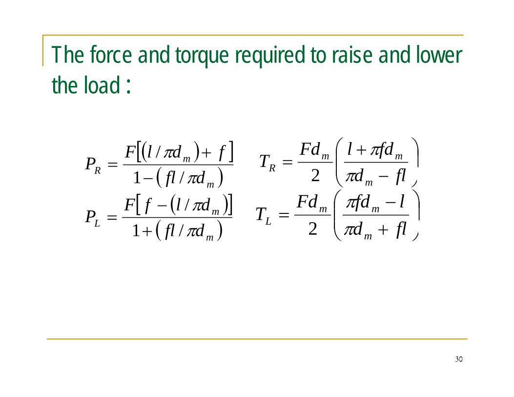
The force and torque required to raise and lower the load :
( )[ ]( )
mR dfl
fdlFP
π/1
/ += ⎟
⎠
⎞⎜⎜⎝
⎛ +=
fldfdlFd
T mmR π
π2( )
( )[ ]( )
mL
mR
dlfFP
dflππ/
/1−
=
− ⎠⎜⎝ − fldmπ2
⎟⎠
⎞⎜⎜⎝
⎛ −=
fldlfdFd
T mmL
π2( )m
L dfl π/1+ ⎠⎜⎝ + fldm
L π2
30
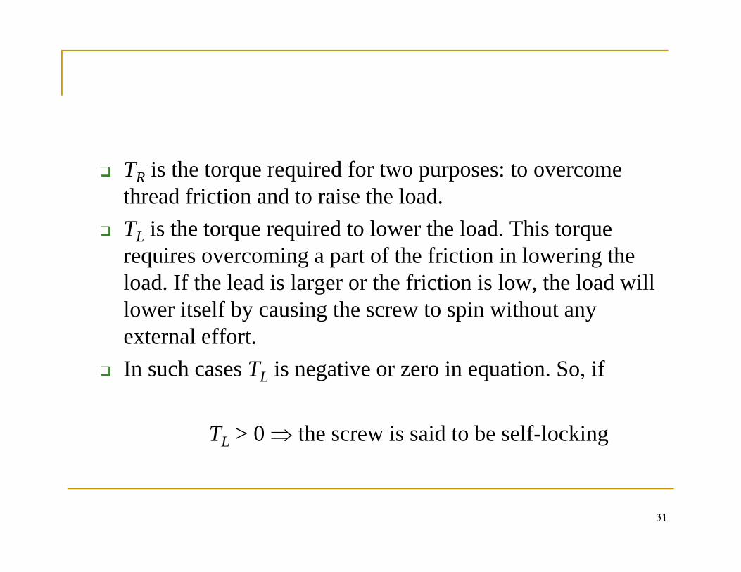
TR is the torque required for two purposes: to overcome R q q p pthread friction and to raise the load.TL is the torque required to lower the load. This torque
i i t f th f i ti i l i threquires overcoming a part of the friction in lowering the load. If the lead is larger or the friction is low, the load will lower itself by causing the screw to spin without any external effort. In such cases TL is negative or zero in equation. So, if
TL > 0 ⇒ the screw is said to be self-locking
31
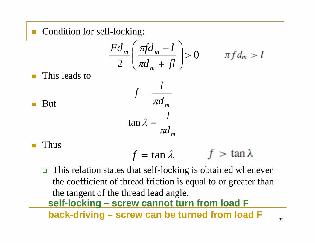
Condition for self-locking:
⎞⎛ lfdFd
This leads to
02
>⎟⎟⎠
⎞⎜⎜⎝
⎛+−
fldlfdFd
m
mm
ππ
This leads to
But mdlf
π=
But m
mdl
πλ =tan
Thus
Thi l ti t t th t lf l ki i bt i d hλtan=f
This relation states that self-locking is obtained whenever the coefficient of thread friction is equal to or greater than the tangent of the thread lead angle.
32
self-locking – screw cannot turn from load Fback-driving – screw can be turned from load F
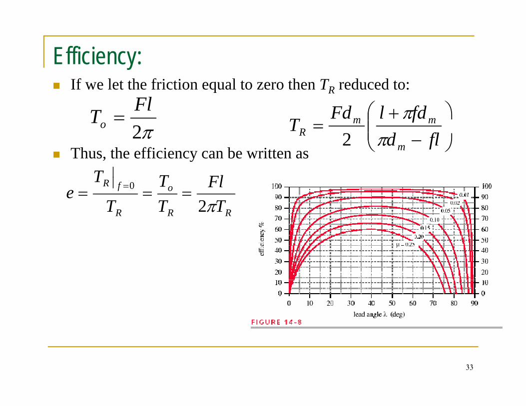
Efficiency:If we let the friction equal to zero then TR reduced to:
2FlTo = ⎞
⎜⎜⎛ +
=fdlFd
T mm π
Thus, the efficiency can be written asπ2o
FlTT
⎠⎜⎜⎝ −
=fld
Tm
R π2
RR
o
R
fR
TFl
TT
T
Te
π20 === =
33
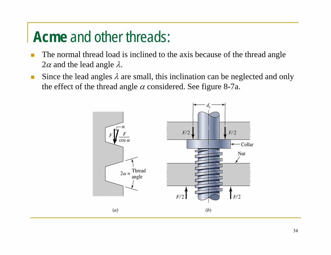
Acme and other threads:The normal thread load is inclined to the axis because of the thread angle 2α and the lead angle λ.Since the lead angles λ are small, this inclination can be neglected and only g , g ythe effect of the thread angle α considered. See figure 8-7a.
34
Thus the friction term in the torque equation TR must be divided by cosα, for raising the load, or for tightening a screw or bolt, this yieldsor bolt, this yields
⎟⎟⎠
⎞⎜⎜⎝
⎛−
+=
απαπ
secsec
2 fldfdlFd
Tm
mmR
This equation is an approximate equation because λ is neglected.
⎠⎝ fm
• Acme thread is not as efficient as the square thread, because of the additional friction due to the wedging action, b t it i ft f d b it i i t hibut it is often preferred because it is easier to machine
35
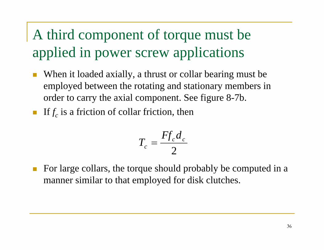
A third component of torque must be applied in power screw applications
When it loaded axially, a thrust or collar bearing must be y, gemployed between the rotating and stationary members in order to carry the axial component. See figure 8-7b.If f i f i ti f ll f i ti thIf fc is a friction of collar friction, then
ccdFfT
For large collars, the torque should probably be computed in a
2cc
cf
T =
g , q p y pmanner similar to that employed for disk clutches.
36
Stresses in Power Screws
Stresses in ThreadsBody Stresses
AxialTorsionTorsion
Thread StressesBearingBending
Buckling
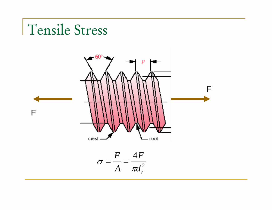
Tensile Stress
F
F
2
4
rdF
AF
πσ ==
rdA π
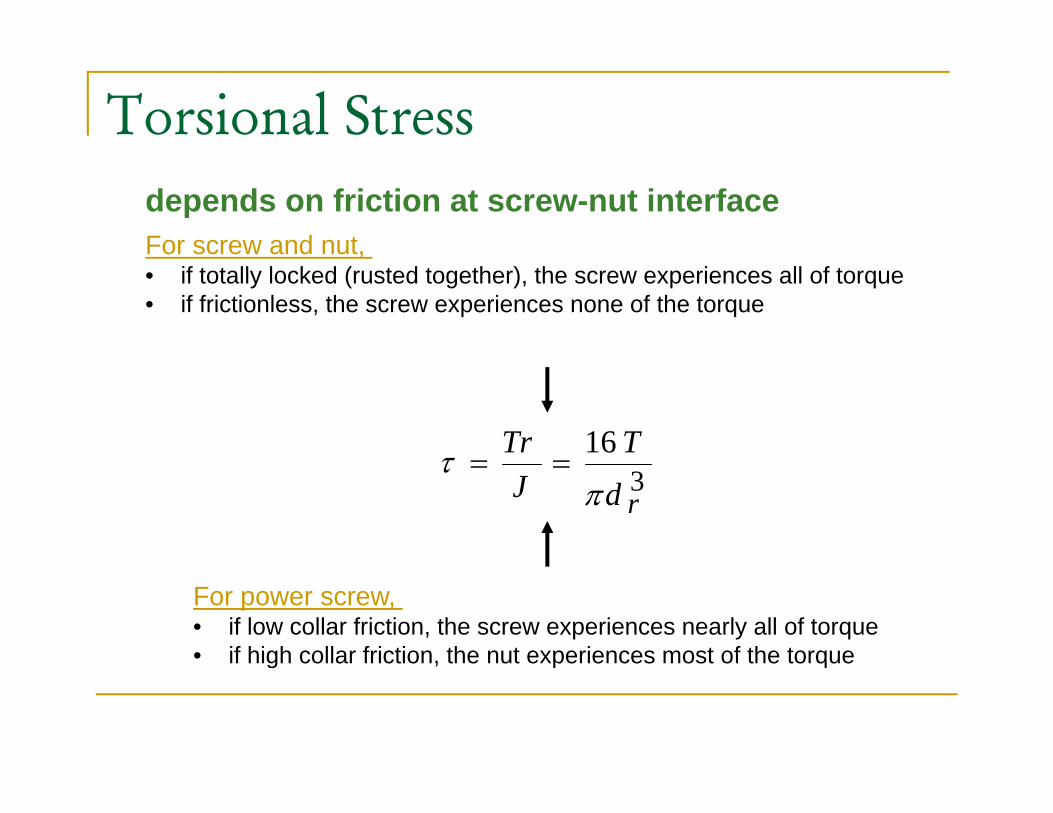
Torsional Stressdepends on friction at screw-nut interfaceFor screw and nut,For screw and nut, • if totally locked (rusted together), the screw experiences all of torque• if frictionless, the screw experiences none of the torque
16 TTrτ 3rdJ π
τ ==
For power screw, • if low collar friction, the screw experiences nearly all of torque• if high collar friction, the nut experiences most of the torqueif high collar friction, the nut experiences most of the torque
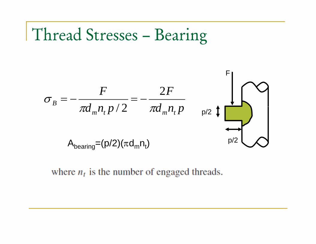
Thread Stresses – Bearing
F
pndF
pndF
B ππσ 2
2/−=−=
p/2
/2
pndpnd tmtm ππ 2/
p/2Abearing=(p/2)(πdmnt)
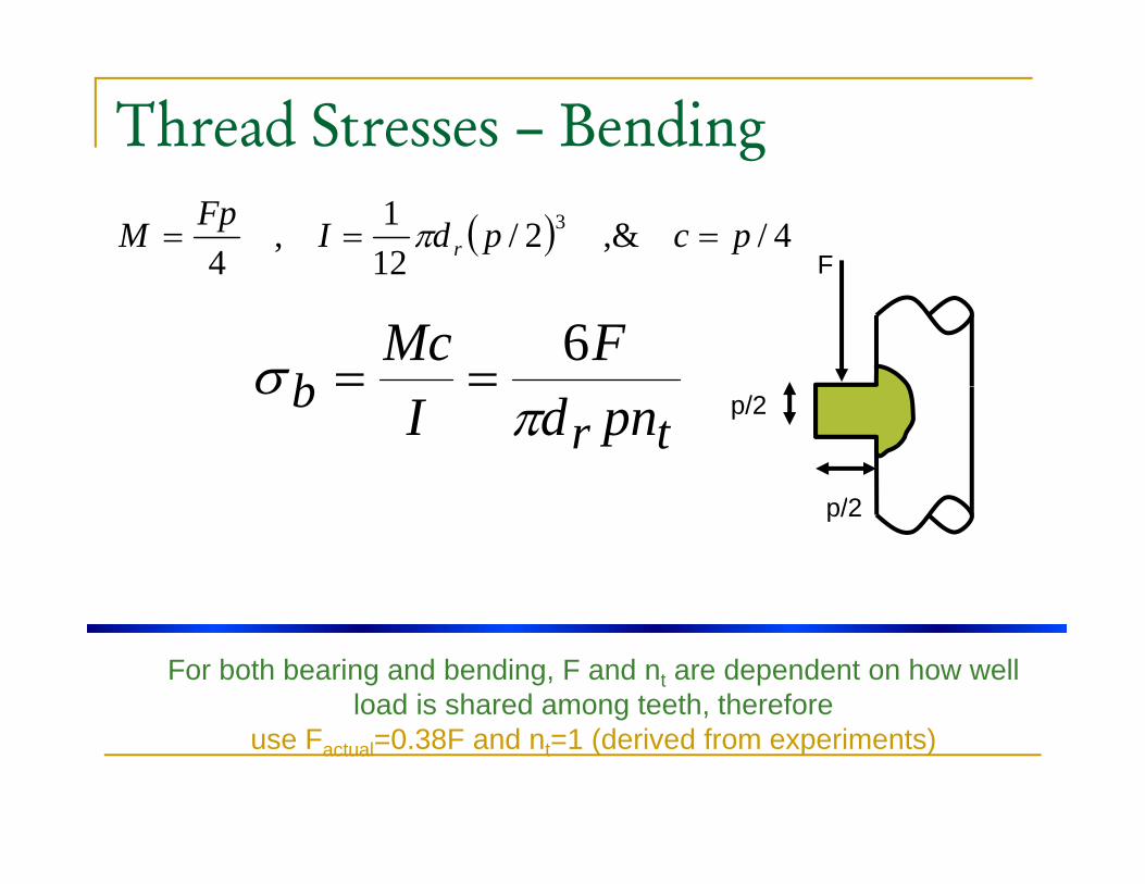
Thread Stresses – Bending
F( ) 4/,&2/
121,
43 pcpdIFpM r === π
bFMcσ 6
==p/2
/2
trb pndI π
σ
p/2
For both bearing and bending, F and nt are dependent on how well load is shared among teeth, therefore
use Factual=0.38F and nt=1 (derived from experiments)

Thread Stresses – Transverse shear stresses
At top of tooth the transverse shear stress is zero
Th V Mi ’ t th t f th t “ l ” i f d bThe Von Mises σ’ at the top of the root “plane” is found by first identifying the orthogonal normal stresses and the shear stresses.
42
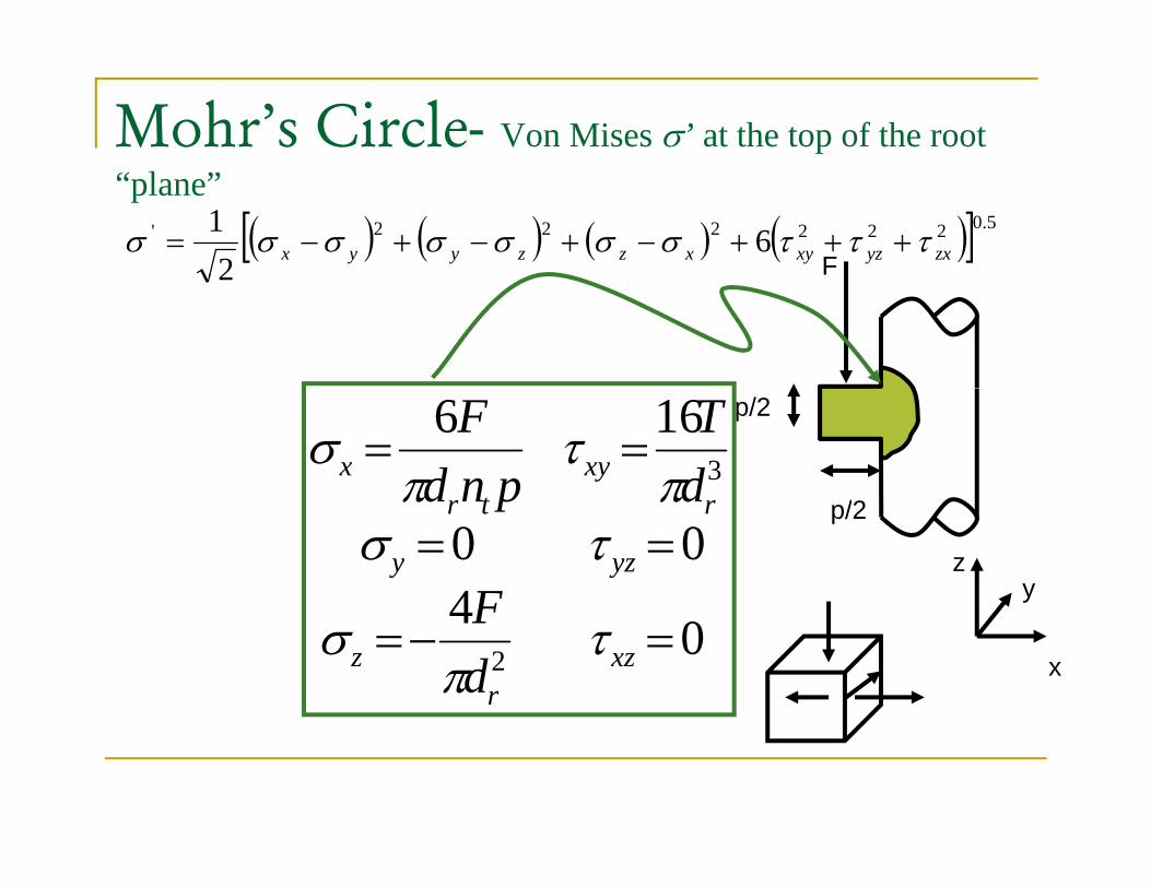
Mohr’s Circle- Von Mises σ’ at the top of the root “plane”
F( ) ( ) ( ) ( )[ ] 5.0222222' 6
21
zxyzxyxzzyyx τττσσσσσσσ +++−+−+−=2
p/2
/2
1663== xy
tx d
Tpnd
Fπ
τπ
σp/2
400 == yzy
rtr
F
dpndτσ
ππ
yz
042 =−= xzr
z dF τ
πσ
x
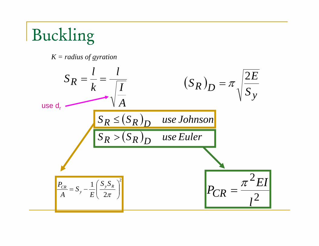
Buckling
llS ( ) E2
K = radius of gyration
AIk
SR == ( )y
DR SES 2π=
use dr
( )( ) EuleruseSS
JohnsonuseSS
DRR
DRR>
≤use dr
( ) EuleruseSS DRR >
2
21
⎟⎟⎠
⎞⎜⎜⎝
⎛−=
πRy
yCR SS
ES
AP
2
2
lEIPCR
π=
l
The engaged threads cannot share the load equally.Some experiments show that the first engaged threadcarries 0.38 of the load, the second 0.25, the third0 18 and the seventh is free of load0.18, and the seventh is free of load.
I ti ti th d t b th ti bIn estimating thread stresses by the equations above,substituting 0.38F for F and setting nt to 1 will givethe largest level of stresses in the thread-nutthe largest level of stresses in the thread nutcombination.
4545
Example: 8-1A square-thread power screw has a major diameter of 32mm and a pitch of 4mm with double threads. The given data i l d f f 0 08 d 40 d F 6 4kNinclude f = fc =0.08, dc = 40mm, and F = 6.4kN per screw. Determine:
1 The thread depth thread width pitch diameter minor1. The thread depth, thread width, pitch diameter, minor diameter, and lead.
2. The torque required to raise and lower the load3. The efficiency during lifting the load4. The body stresses, torsional and compressive5. The bearing stress6. The thread stress bending at the root, shear at the root, and
Von Mises stress
46
Von Mises stress
Solution
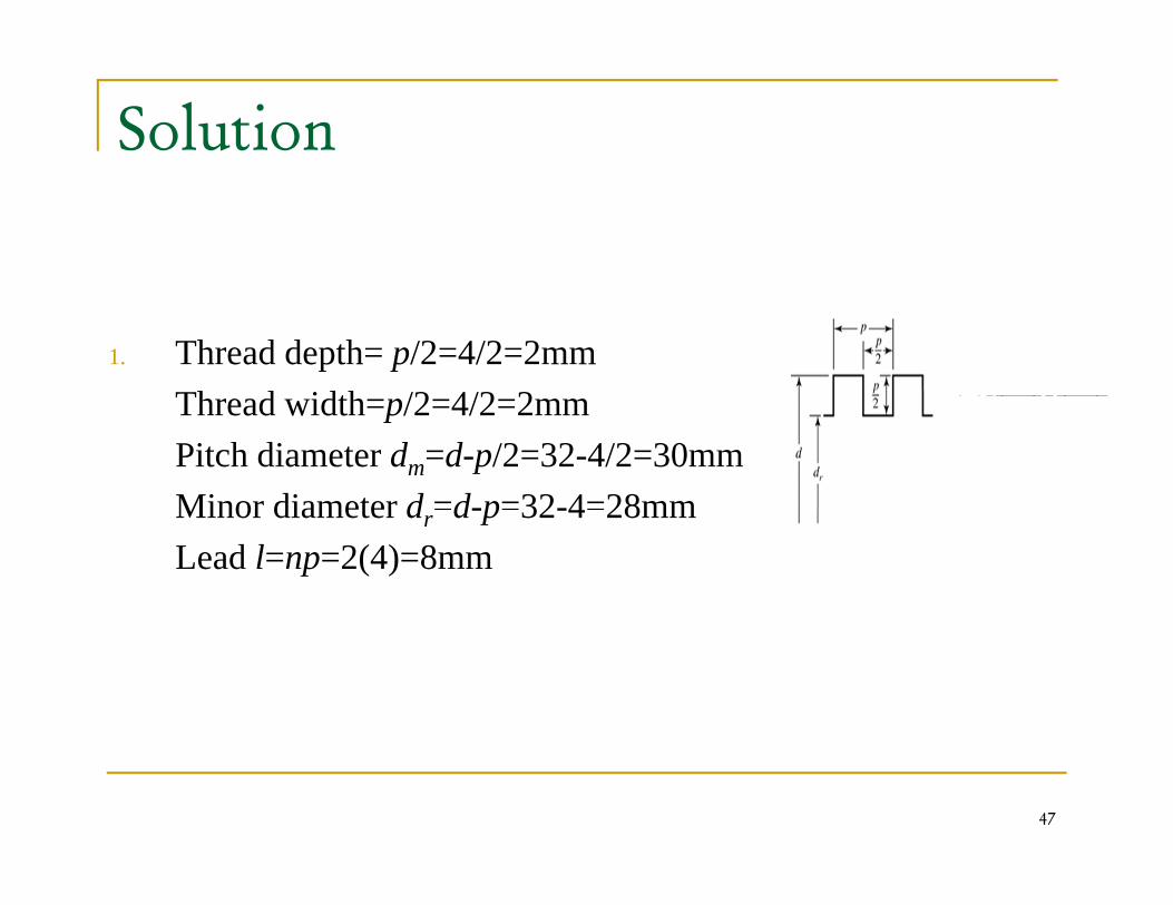
1. Thread depth= p/2=4/2=2mmTh d idth /2 4/2 2Thread width=p/2=4/2=2mmPitch diameter dm=d-p/2=32-4/2=30mmMinor diameter d =d-p=32-4=28mmMinor diameter dr d-p 32-4 28mmLead l=np=2(4)=8mm
47
Solution…
2. Using equation (8-1) and (8-6), the torque required to turn g q ( ) ( ), q qthe screw against the load is:
dFffdlFd ⎞⎜⎛ + π
mNdFf
fldfdlFd
T cc
m
mmR .18.2624.1094.15
22=+=+⎟
⎠
⎞⎜⎜⎝
⎛−
+=
ππ
Using equation (8-2) and (8-6), the load-lowering torque is:
NdFffdlFd
T ccmm 77924104660⎞
⎜⎛ −π
mNf
fldf
T cc
m
mmL .77.924.10466.0
22=+−=+⎟
⎠
⎞⎜⎜⎝
⎛+
=π
48
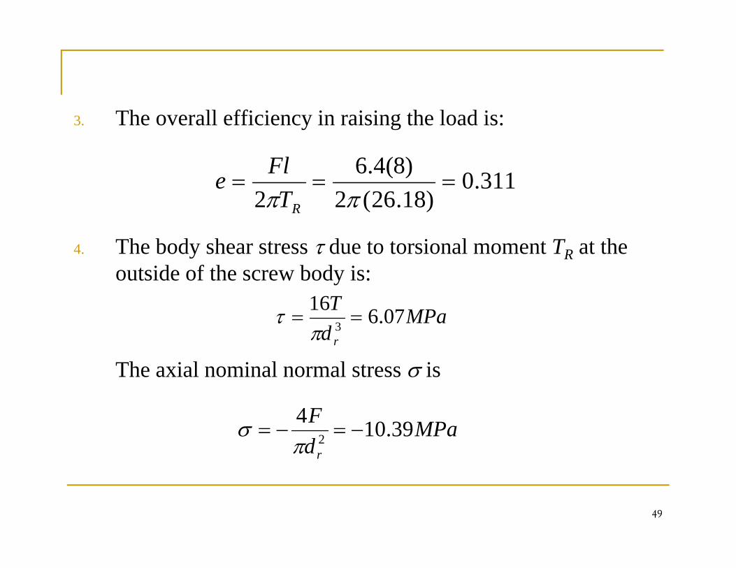
3. The overall efficiency in raising the load is:
3110)8(4.6Fl
4 The body shear stress τ due to torsional moment T at the
311.0)18.26(2
)(2
===ππ RT
e
4. The body shear stress τ due to torsional moment TR at the outside of the screw body is:
MPaT 07616==τ
The axial nominal normal stress σ is
MPadr
07.63 ==π
τ
MPadF
r
39.1042 −=−=
πσ
49
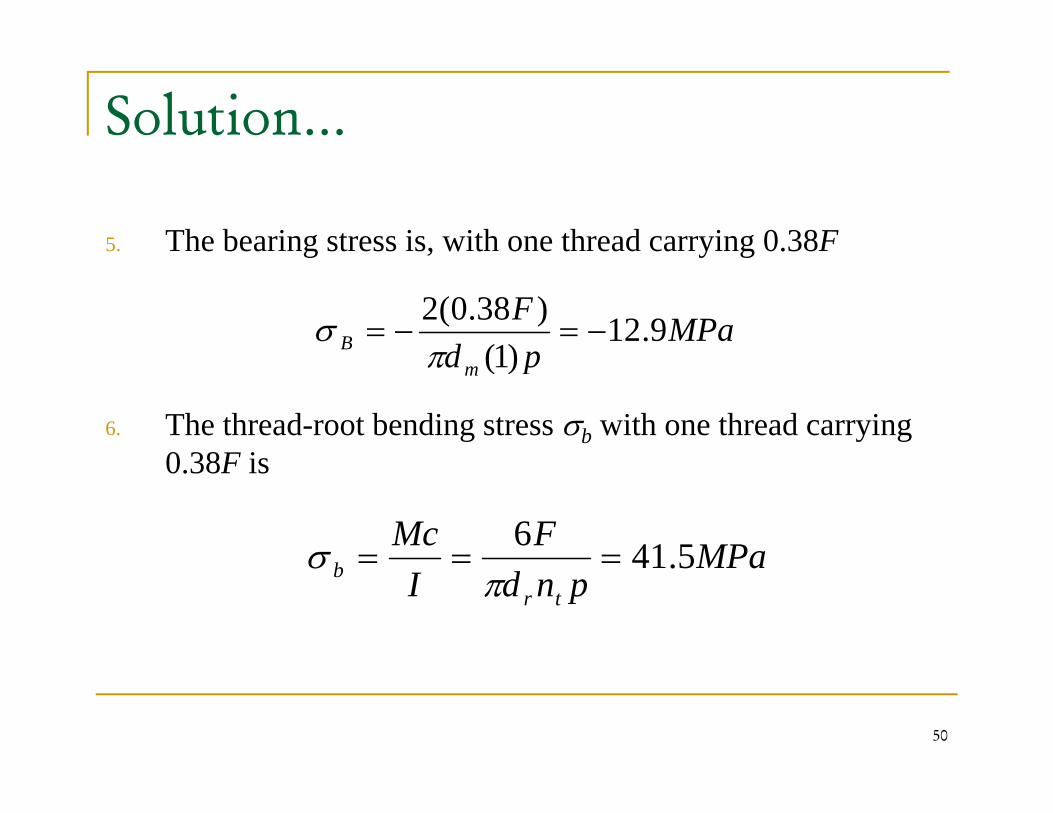
Solution…
5. The bearing stress is, with one thread carrying 0.38Fg , y g
MPapd
FB 9.12
)1()38.0(2
−=−=π
σ
6. The thread-root bending stress σb with one thread carrying 0 38F i
pd m )1(π
0.38F is
MPaFMc 5416===σ MPa
pndI trb 5.41===
πσ
50
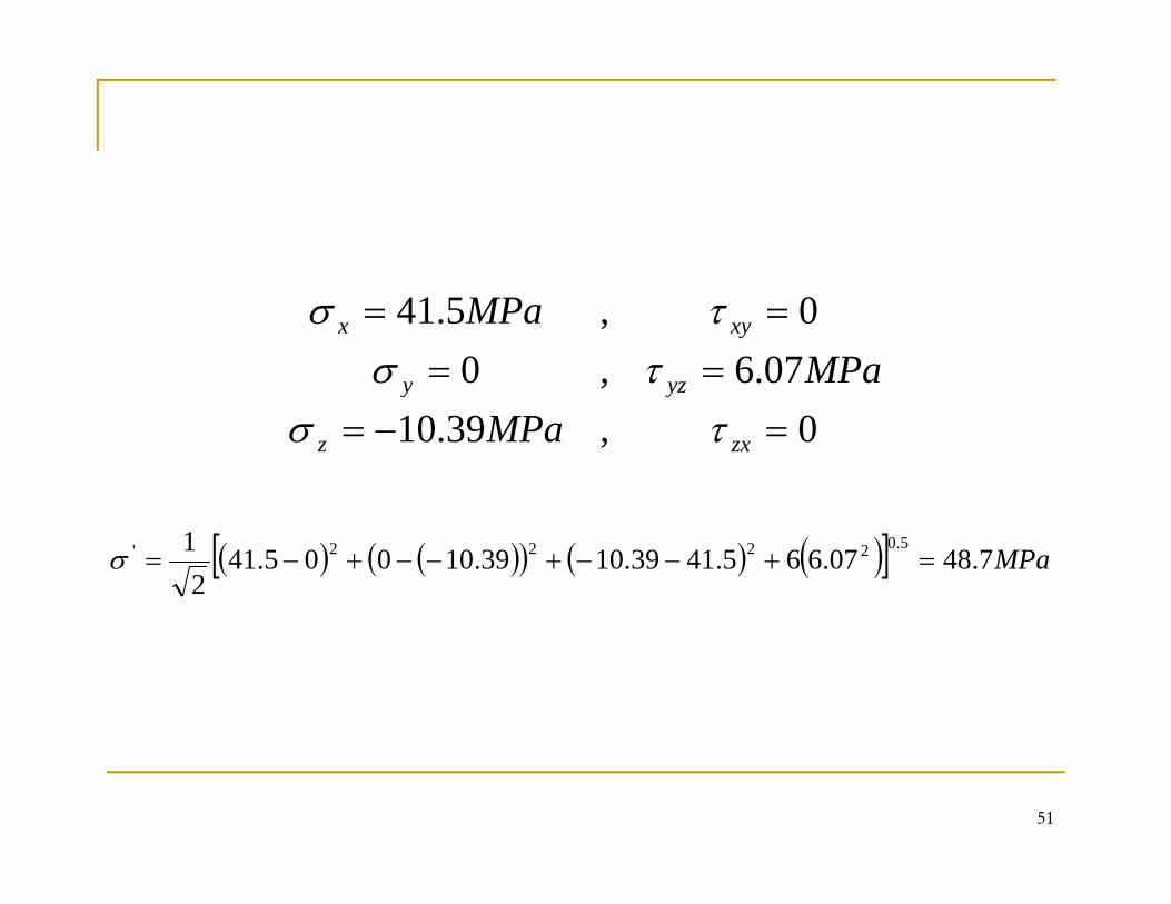
07.6,00,5.41
====
yzy
xyx
MPaMPa
τστσ
0,39.10 =−= zxz
yy
MPa τσ
( ) ( )( ) ( ) ( )[ ] MPa7.4807.665.4139.1039.10005.412
1 5.02222' =+−−+−−+−=σ
51
52
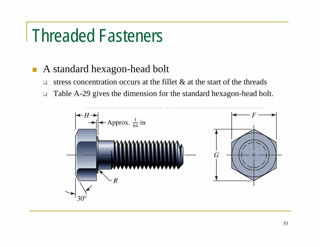
Threaded FastenersA standard hexagon-head bolt
stress concentration occurs at the fillet & at the start of the threadsTable A-29 gives the dimension for the standard hexagon-head bolt.
53
The diameter of the washer face is the same as the width across flats of the hexagonThe threads length of metric bolts is
⎪⎨
⎧≤<+
≤≤+200125122
4812562LD
DLDL
Ideal bolt length is one in which only one or two threads project from the
⎪⎩
⎪⎨
>+≤<+=
200252200125122
LDLDLT All dimensions in mm
Ideal bolt length is one in which only one or two threads project from the nut after it is tightened.Bolt holes may have burrs and sharp edges after drilling. These could bite into the fillet and increase stress concentration Therefore washers mustinto the fillet and increase stress concentration. Therefore, washers must always be used under the bolt head to prevent this.Sometimes it is necessary to use washers under the nut too.
54
The purpose of a bolt is to clamp two or more parts together.p p p p gThe clamping load stretches or elongates the bolt;
The load is obtained by twisting the nut until the bolt has elongated almost to the elastic limit.If the nut does not loosen, this bolt tension remains as preload or clamping forcepreload or clamping force.
55
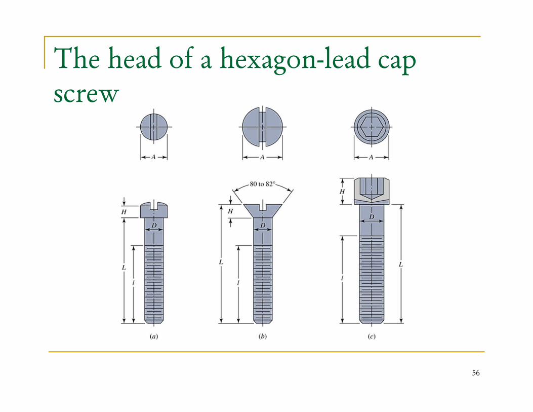
The head of a hexagon-lead cap screw
56
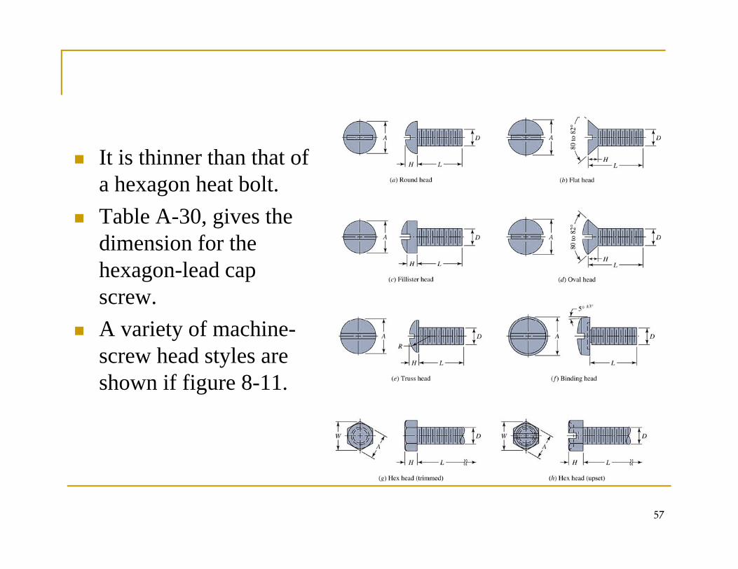
It is thinner than that of h h b la hexagon heat bolt.
Table A-30, gives the dimension for thedimension for the hexagon-lead cap screw.A variety of machine-screw head styles are shown if figure 8-11.g
57
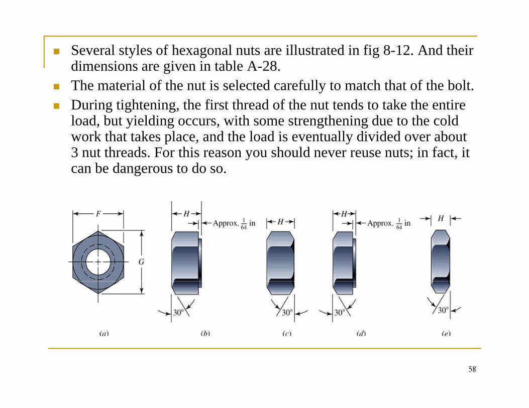
Several styles of hexagonal nuts are illustrated in fig 8-12. And their dimensions are given in table A-28. The material of the nut is selected carefully to match that of the bolt. During tightening, the first thread of the nut tends to take the entire load, but yielding occurs, with some strengthening due to the cold , y g , g gwork that takes place, and the load is eventually divided over about 3 nut threads. For this reason you should never reuse nuts; in fact, it can be dangerous to do so.
58
Tension Connections-The fastener Stiffness
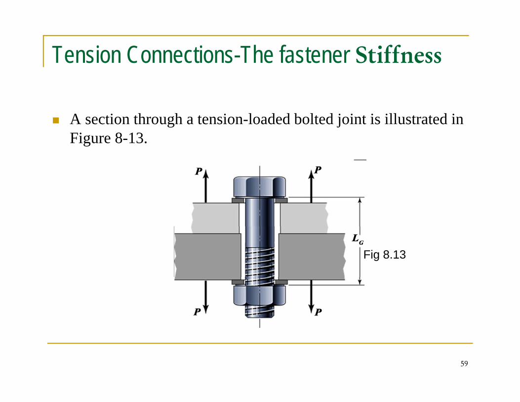
A section through a tension-loaded bolted joint is illustrated in g jFigure 8-13.
Fig 8.13
59
The purpose of the bolt is to clamp the two or more partsThe purpose of the bolt is to clamp the two or more partstogether.Twisting the nut stretches the bolt to produce the clamping force. This clamping force is called the Pretension or Bolt Preload. It exists in the connection after the nut has been properly tightened no matter whether the external tensile load p ope y g e ed o e w e e e e e e s e o dP is exerted or not.Since the members are being clamped together, the clampingforce which produces tension in the bolt induces compressionforce which produces tension in the bolt induces compressionin the members.The spring constant, or stiffness constant, of an elastic membersuch as a bolt, is the ratio between the force applied to thesuch as a bolt, is the ratio between the force applied to themember and the deflection produced by that force.Thus,
The defection is defined by EAFl
=δ
60
The defection is defined by
The spring rate
EA
lEAk =
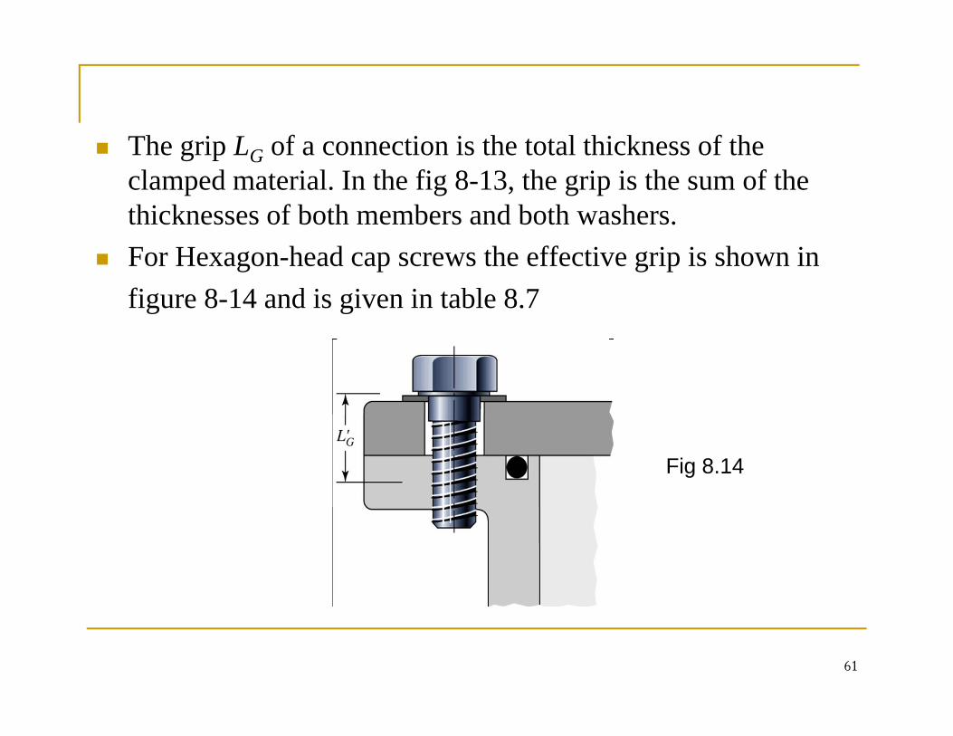
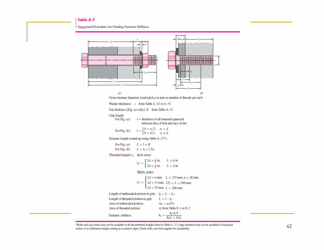
Th i L f i i h l hi k f hThe grip LG of a connection is the total thickness of the clamped material. In the fig 8-13, the grip is the sum of the thicknesses of both members and both washers.For Hexagon-head cap screws the effective grip is shown in figure 8-14 and is given in table 8.7
Fig 8.14
61
62
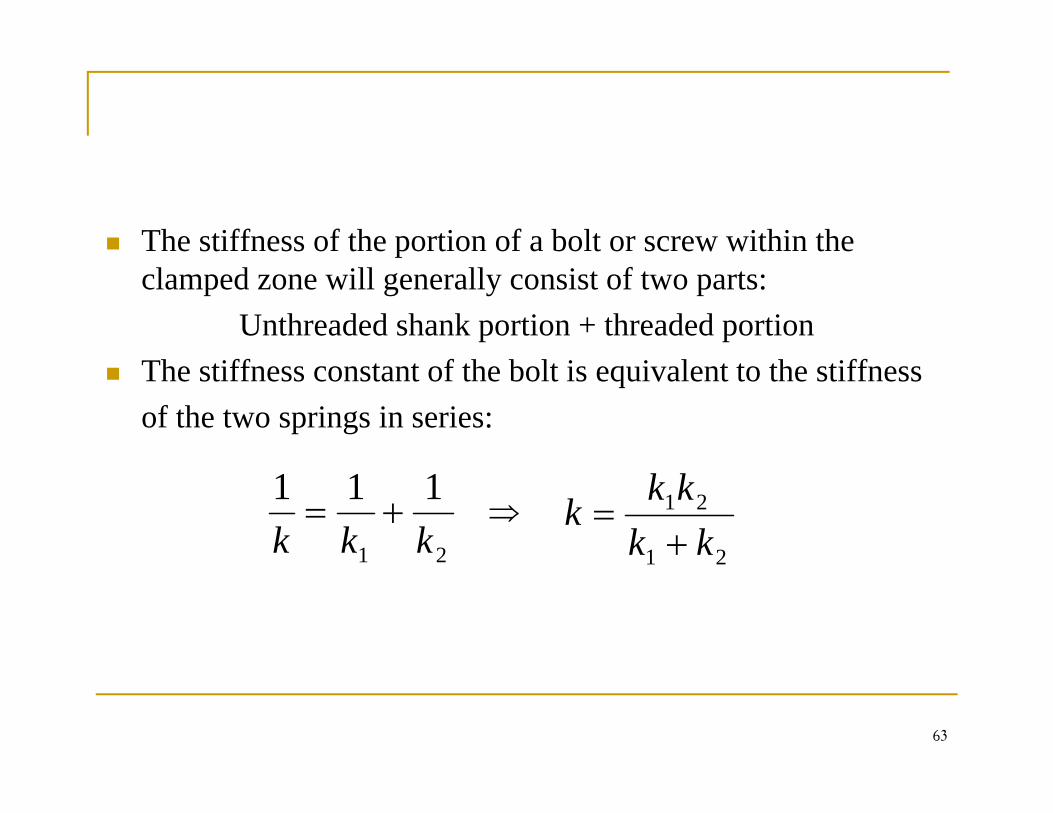
The stiffness of the portion of a bolt or screw within the pclamped zone will generally consist of two parts:
Unthreaded shank portion + threaded portionThe stiffness constant of the bolt is equivalent to the stiffness of the two springs in series:
⇒21
111kkk
+=21
21
kkkk
k+
=21 21
63
Thus, spring rates of the threaded and unthreaded portions of , p g pthe bolt in the clamped zone are respectively:
dt EAk
EAk
Wh
d
dd
t
tt l
kl
k == ,
WhereAt= tensile-stress area (table 8-1, 8-2)l = length of threaded portion of griplt length of threaded portion of gripAd= major-diameter area of fastenerld=length of unthreaded portion in grip
64
d g p g p
Substituting these stiffness, we get:
tdb
Ekkk =
Where k is the estimated effective stiffness of the bolt or cap
dttdb lklk
k+
Where kb is the estimated effective stiffness of the bolt or cap screw in the clamped zone.For short fasteners, the one in figure 8-14 the unthreaded area , gis small and so the first of the expression kt is used to find kb.For long fasteners, the threaded area is relatively small, and so h d i k i d fi d kthe second expression kd is used to find kb.
65
Joins-Member stiffness (Tension Connection-the Members)
In previous section, we determined the stiffness of the fastener p ,in the clamped zone.In this section, we will study the stiffness of the members in th l dthe clamped zone. There may be more than two members included in the grip of the fastener. t e aste e .Thus, Total spring rate of the member:
1111+++ 8 18
im kkkk....
21
+++= 8.18
66
If one of the members is a soft gasket g⇒ kgasket < others members
Thus, we can neglect all stiffness and only the gasket stiffness used.If there is no gasket, the stiffness of the members is rather difficult to obtain except by experimentation because thedifficult to obtain, except by experimentation, because the compression spreads out between the bolt head and the nut and hence the area is not uniform.
67
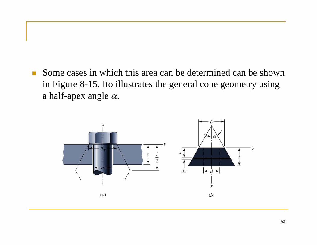
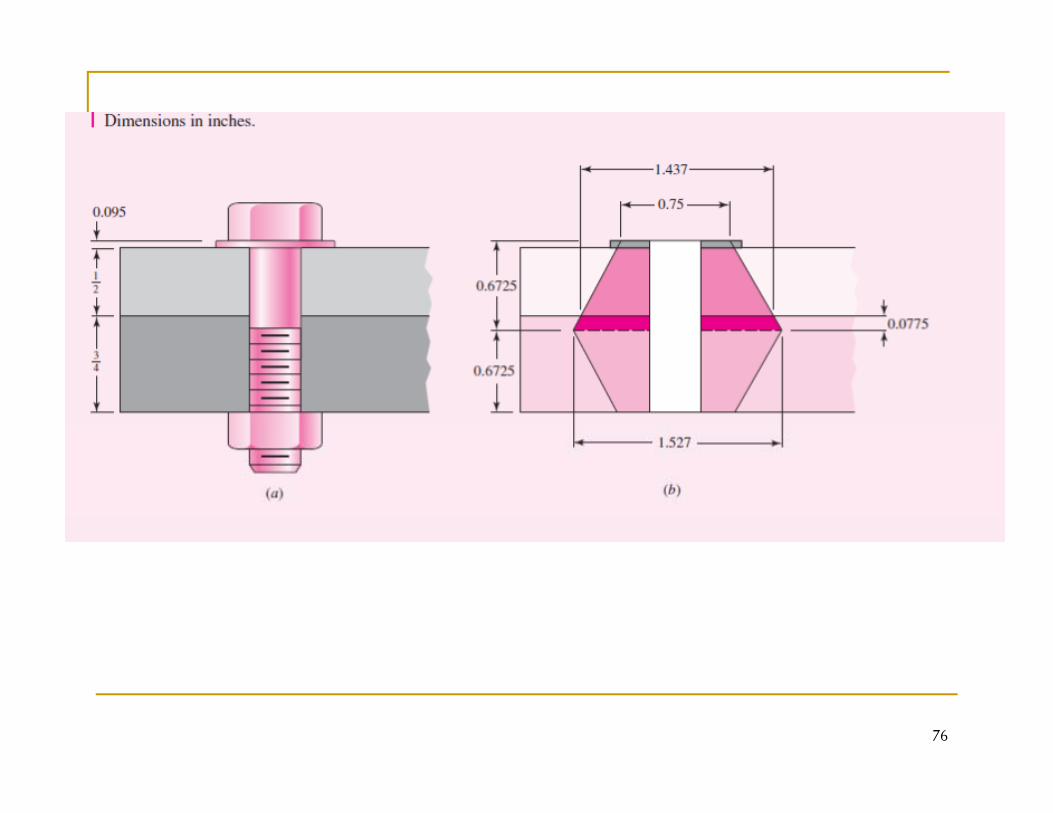
Some cases in which this area can be determined can be shown in Figure 8-15. Ito illustrates the general cone geometry using a half-apex angle α.
68
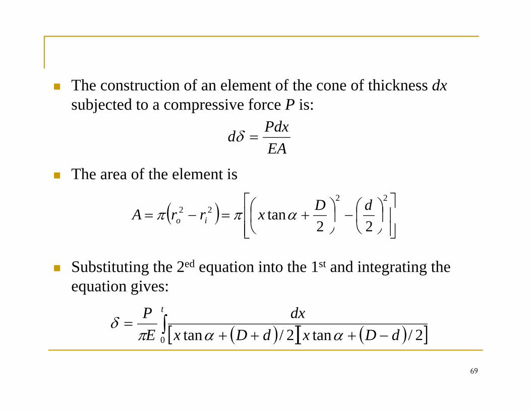
The construction of an element of the cone of thickness dxsubjected to a compressive force P is:
Pdx
The area of the element isEAPdxd =δ
e a ea o t e e e e t s
( )⎥⎥⎦
⎤
⎢⎢⎣
⎡⎟⎠⎞
⎜⎝⎛−⎟
⎠⎞
⎜⎝⎛ +=−=
2222
22tan dDxrrA io αππ
Substituting the 2ed equation into the 1st and integrating the ti i
⎥⎦⎢⎣ ⎠⎝⎠⎝ 22
equation gives:
( )[ ] ( )[ ]∫ +++=
t
dDxdDxdx
EP
2/tan2/tan ααπδ
69
( )[ ] ( )[ ]−+++ dDxdDxE 0 2/tan2/tan ααπ
70
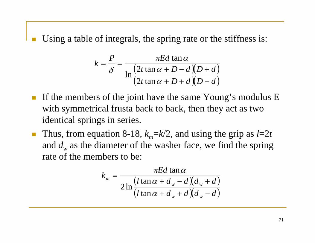
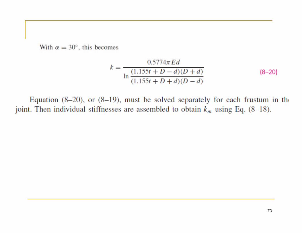
Using a table of integrals, the spring rate or the stiffness is:
( )( )dDdDtEdPk
+−+==
ααπ
δ tan2ln
tan
If the members of the joint have the same Young’s modulus E ith t i l f t b k t b k th th t t
( )( )dDdDt −++αtan2ln
with symmetrical frusta back to back, then they act as two identical springs in series.Thus, from equation 8-18, km=k/2, and using the grip as l=2t, q , m , g g pand dw as the diameter of the washer face, we find the spring rate of the members to be:
Ed( )( )( )( )ddddl
ddddlEdk
ww
wwm
−+++−+
=
αα
απ
tantan
ln2
tan
71
( )( )
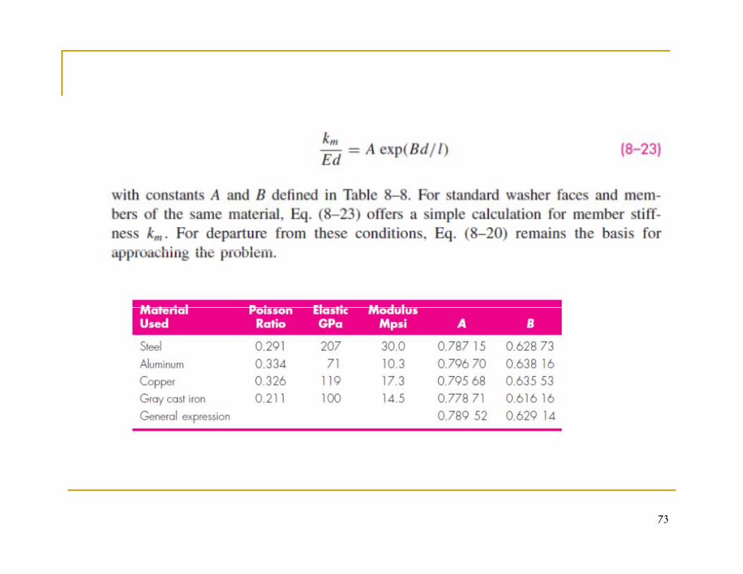
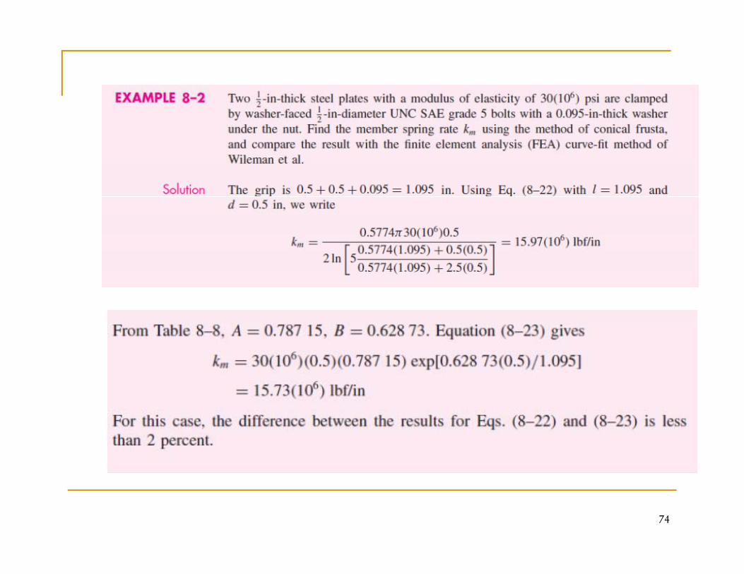
The diameter of the washer face is about 50 percent greater p gthan the fastener diameter for standard hexagon-head bolts and cap screws. Thus we can simplify km equation by letting d =1 5d and if we use α=30odw=1.5d and if we use α=30o
⎞⎜⎛ +
=dl
Edkm 50577405774.0 π
⎠⎞
⎜⎝⎛
++
dldl
5.25774.05.05774.05ln2
72
73
74
75
76
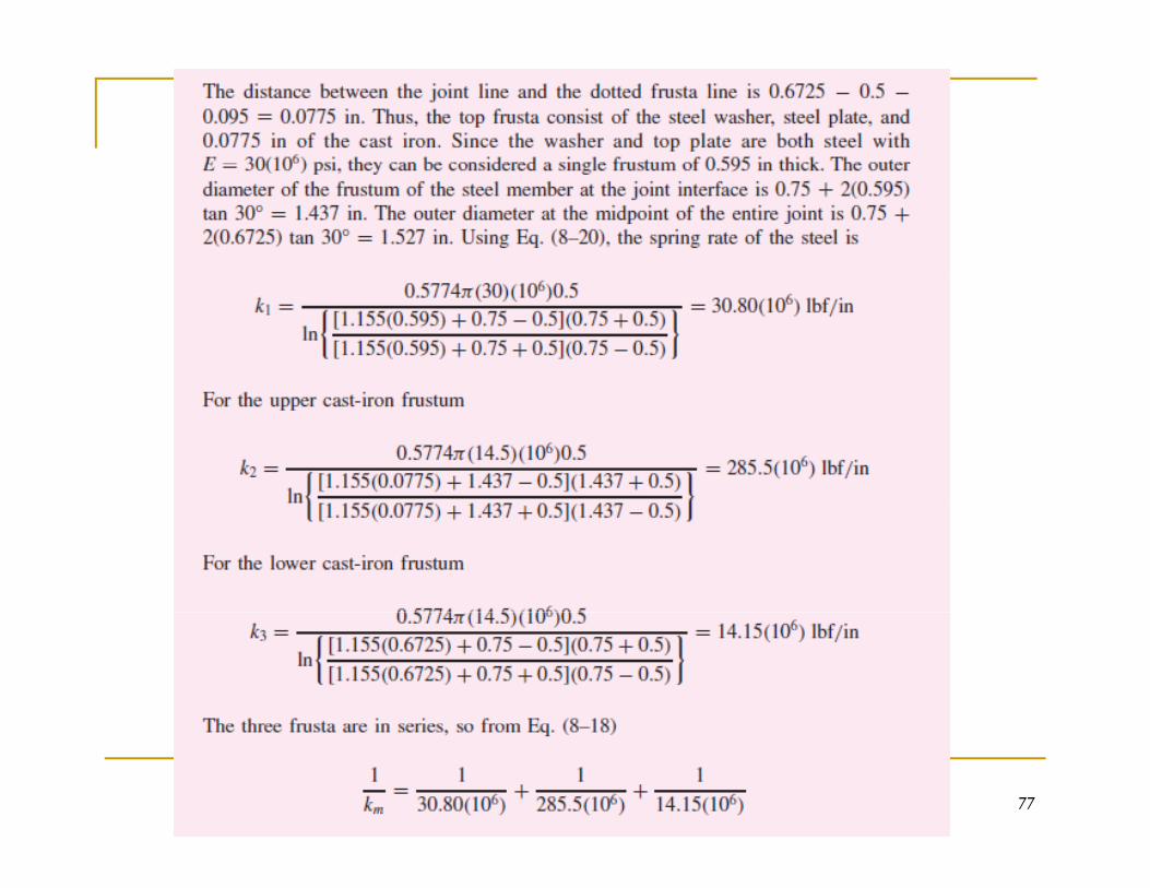
77
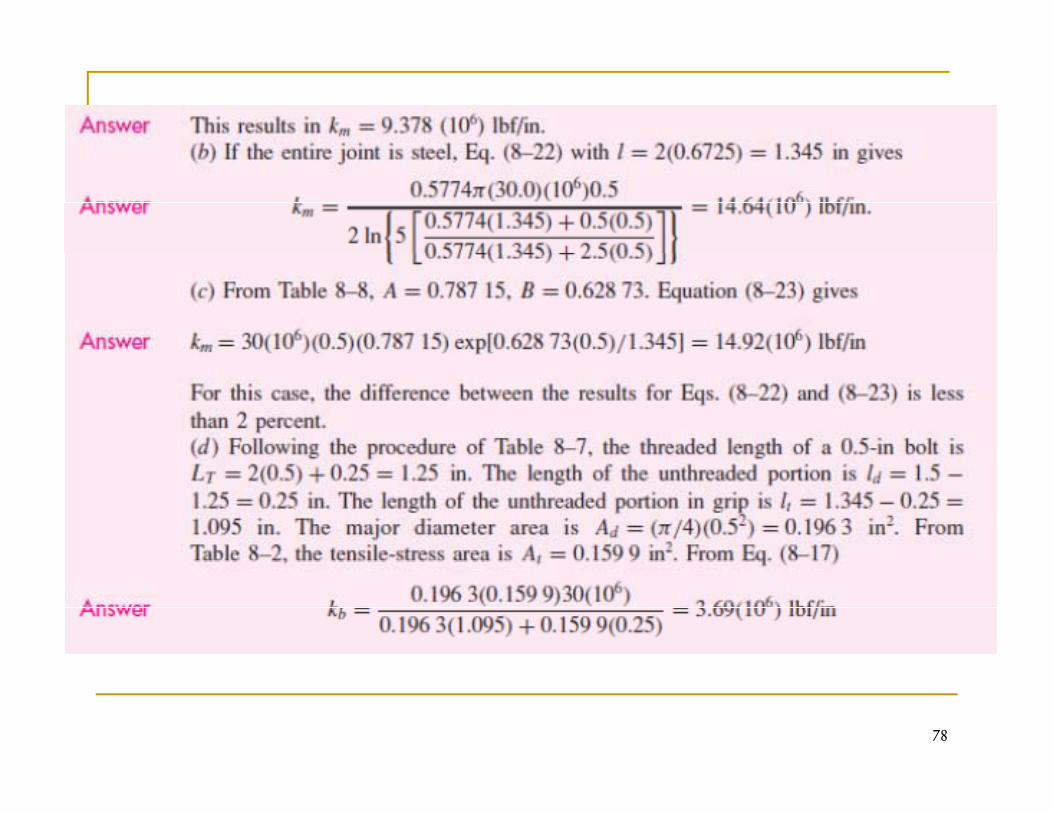
78
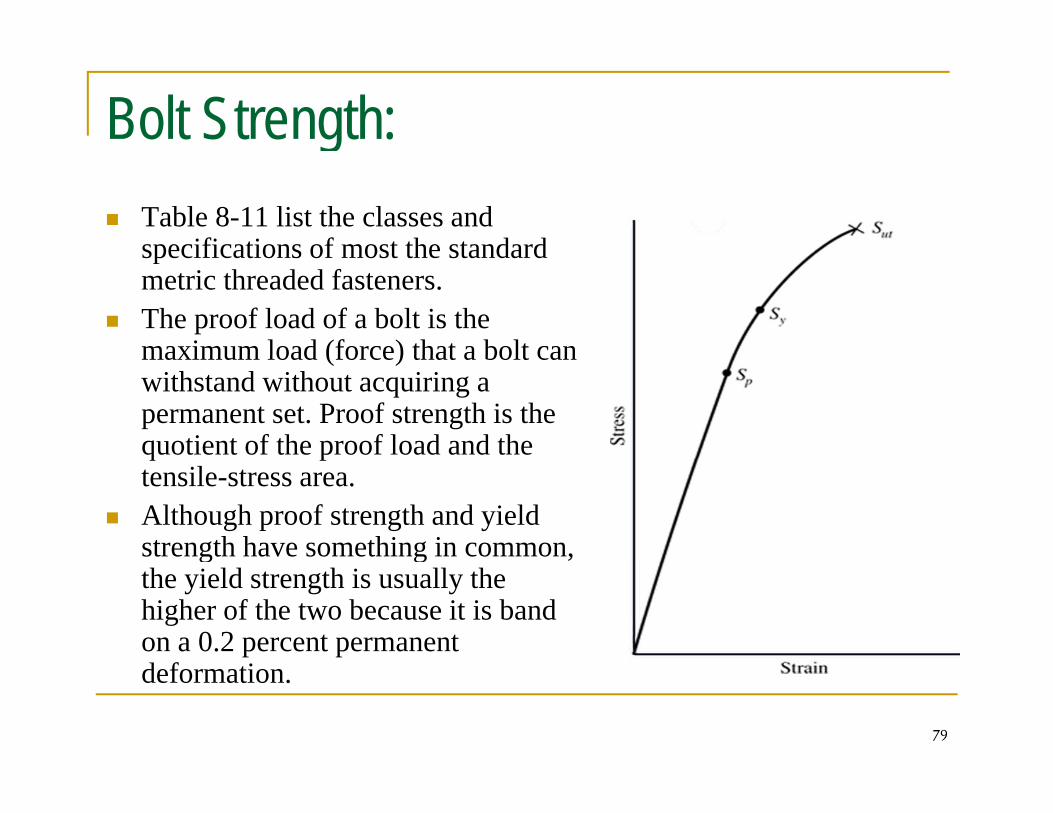
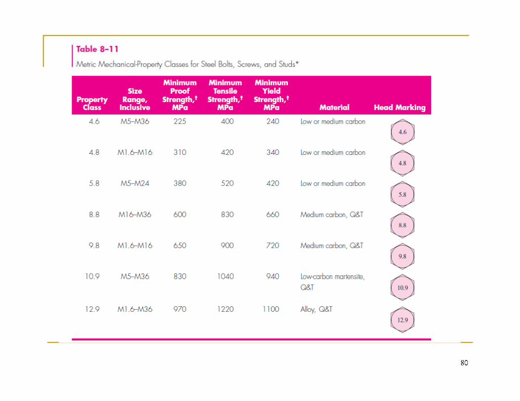
Bolt Strength:gTable 8-11 list the classes and specifications of most the standardspecifications of most the standard metric threaded fasteners. The proof load of a bolt is the maximum load (force) that a bolt canmaximum load (force) that a bolt can withstand without acquiring a permanent set. Proof strength is the quotient of the proof load and the q ptensile-stress area. Although proof strength and yield strength have something in common, g g ,the yield strength is usually the higher of the two because it is band on a 0.2 percent permanent d f i
79
deformation.
80
Tension Joints-The External Load
What happens when an external tensile load P is applied to a b l d i ?bolted connection?
The load P is tension and it causes the connection to stretchThe load P is tension, and it causes the connection to stretch, or elongate, through some distance δ.
It is assumed that the clamping force (the preload Fi) has been correctly applied by tightening the nut before P is applied.
81
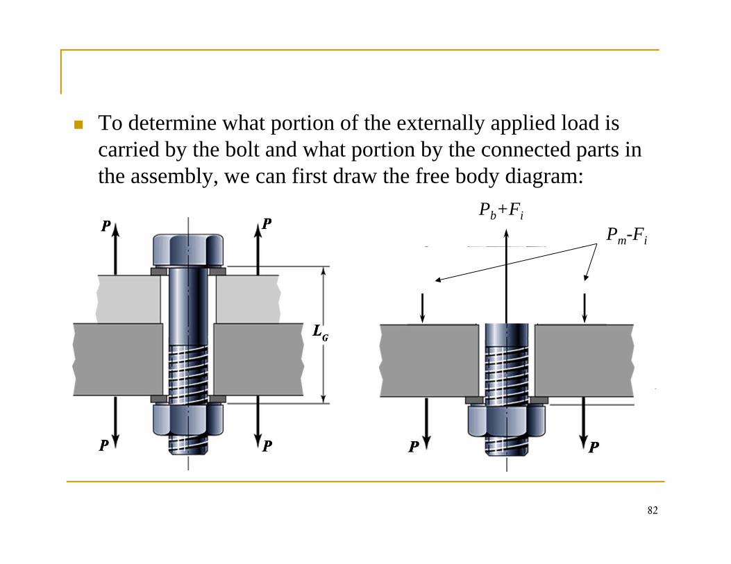
To determine what portion of the externally applied load is carried by the bolt and what portion by the connected parts in the assembly we can first draw the free body diagram:the assembly, we can first draw the free body diagram:
Pm-Fi
Pb+Fi
82
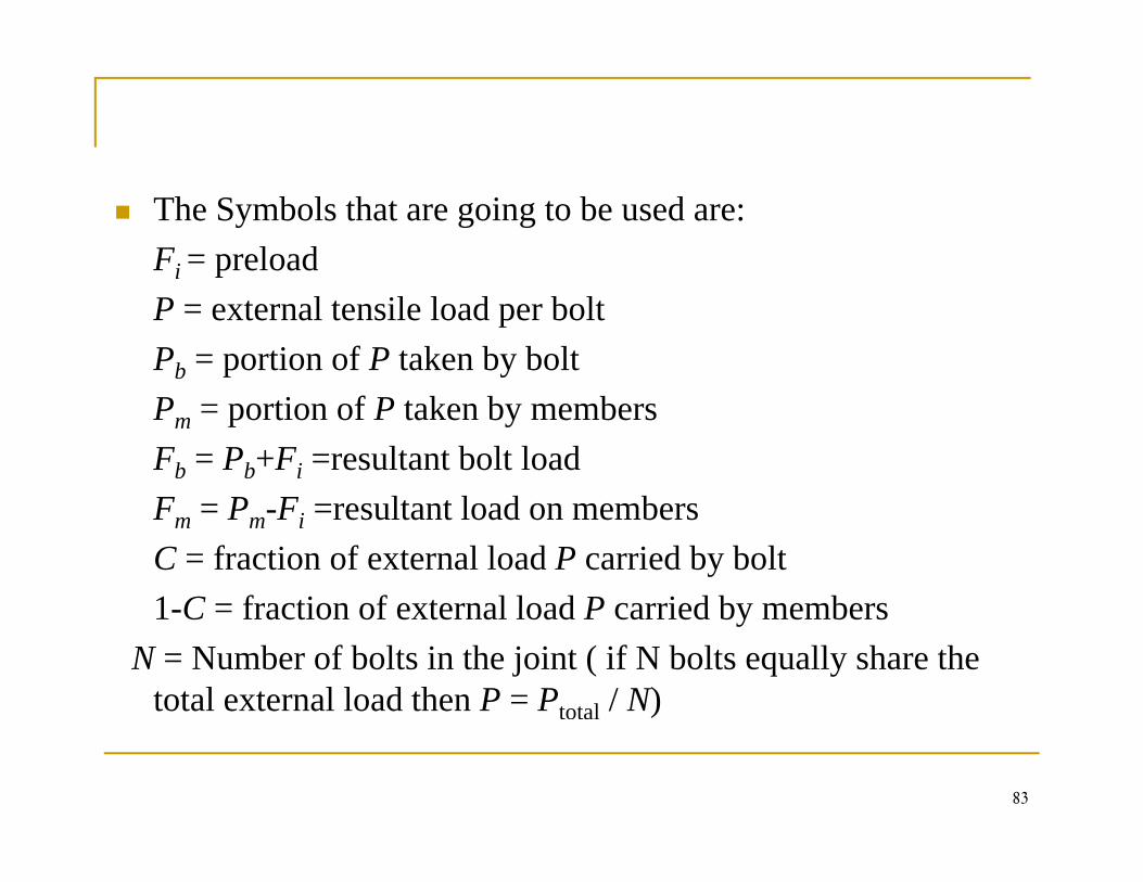
The Symbols that are going to be used are:Fi = preloadi pP = external tensile load per boltPb = portion of P taken by boltPm = portion of P taken by membersFb = Pb+Fi =resultant bolt loadF P F l l d bFm = Pm-Fi =resultant load on membersC = fraction of external load P carried by bolt1 C = fraction of external load P carried by members1-C = fraction of external load P carried by members
N = Number of bolts in the joint ( if N bolts equally share the total external load then P = Ptotal / N)
83
Applying the condition of equilibrium for the forcespp y g q
(1)mb PPP +=
Where
mb
Pb is due to the increased bolt (tensile) forcePm represents the decreased clamping (compression) force between the membersbetween the members
84
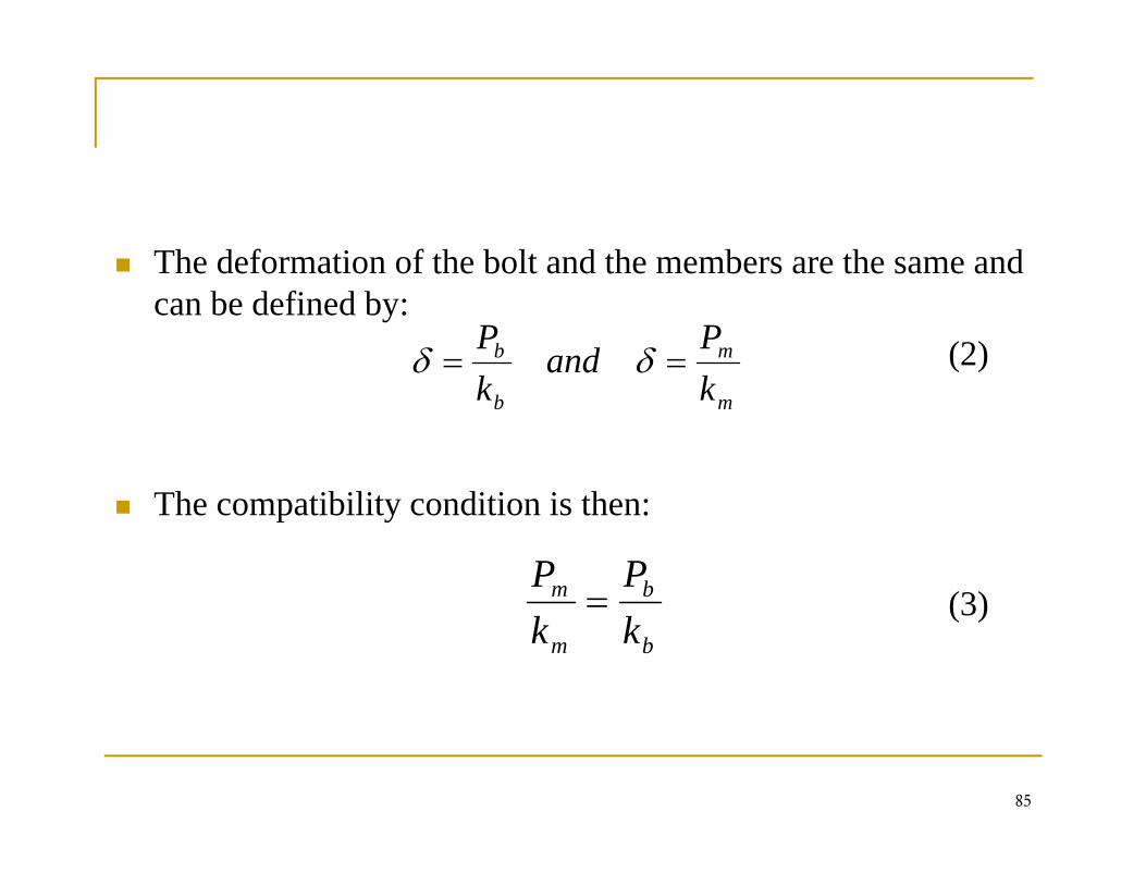
The deformation of the bolt and the members are the same and can be defined by:
(2)mb
kP
andkP
== δδ
Th tibilit diti i th
mb kk
The compatibility condition is then:
(3)bm PP= (3)
bm kk
85
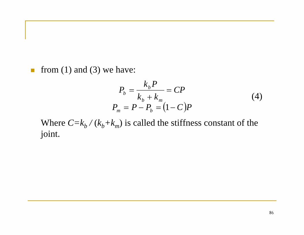
from (1) and (3) we have:( ) ( )
(4)( )
CPkk
PkP
mb
bb =
+=
Where C=kb / (kb+km) is called the stiffness constant of the j i t
( )PCPPP bm −=−= 1
joint.
86
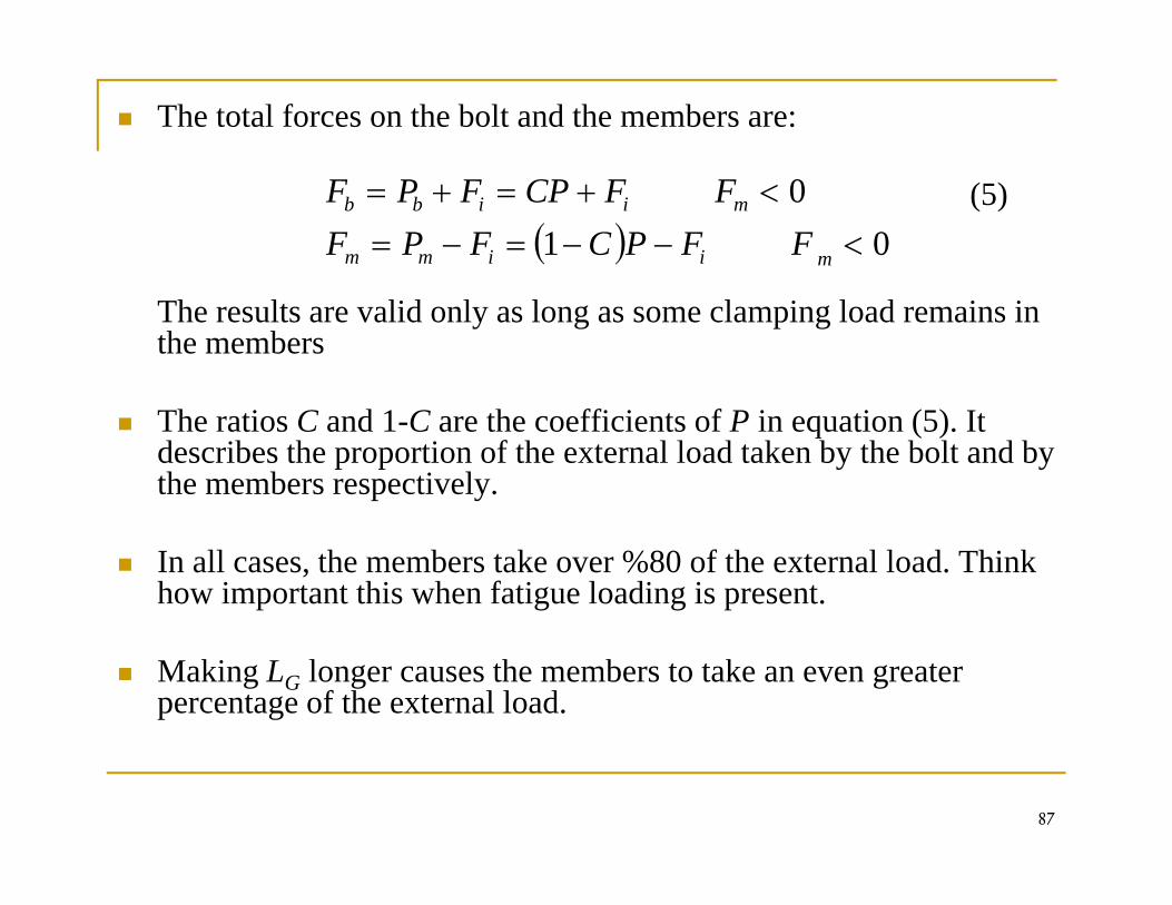
The total forces on the bolt and the members are:
(5)( ) 01
0<−−=−=
<+=+=
miimm
miibb
FFPCFPFFFCPFPF
The results are valid only as long as some clamping load remains in the members
The ratios C and 1-C are the coefficients of P in equation (5). It describes the proportion of the external load taken by the bolt and by the members respectively.
In all cases, the members take over %80 of the external load. Think how important this when fatigue loading is present.
Making LG longer causes the members to take an even greater percentage of the external load.
87
Torque Requirements (Relating Bolt Torque to Bolt Tension)
The most important factor determining the preload in a bolt is p g pthe torque required to tighten the bolt.
The torque may be applied manually by means of a wrench that has a dial attachment indicating the magnitude of the torque being enforced.to que be g e o ced.
Pneumatic or air wrenches give more consistent results than a manual torque wrench and are employed extensively.
88
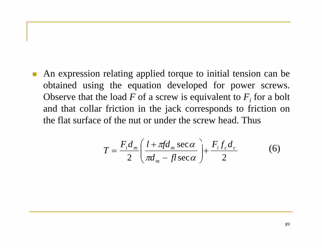
An expression relating applied torque to initial tension can bep g pp qobtained using the equation developed for power screws.Observe that the load F of a screw is equivalent to Fi for a boltand that collar friction in the jack corresponds to friction onand that collar friction in the jack corresponds to friction onthe flat surface of the nut or under the screw head. Thus
⎞⎛ (6)2sec
sec2
cci
m
mmi dfFfld
fdldFT +⎟⎟
⎠
⎞⎜⎜⎝
⎛−
+=
απαπ
89
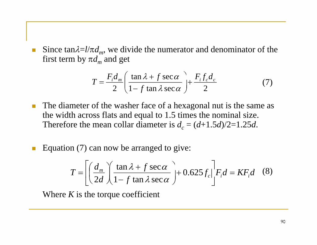
Since tanλ=l/πdm, we divide the numerator and denominator of the first term by πdm and get
sectan dfFfdF ⎞⎛ + αλ(7)
The diameter of the washer face of a hexagonal nut is the same as
2sectan1sectan
2ccimi dfF
ffdFT +⎟
⎠
⎞⎜⎜⎝
⎛−
+=
αλαλ
The diameter of the washer face of a hexagonal nut is the same as the width across flats and equal to 1.5 times the nominal size. Therefore the mean collar diameter is dc = (d+1.5d)/2=1.25d.
Equation (7) can now be arranged to give:
(8)fd⎥⎤
⎢⎡ ⎞
⎜⎛ +⎞
⎜⎛ sectan αλ (8)
Where K is the torque coefficient
dKFdFff
fd
dT iicm =⎥
⎦
⎤⎢⎣
⎡+⎟⎠
⎞⎜⎜⎝
⎛−
+
⎠⎞
⎜⎝⎛= 625.0
sectan1sectan
2 αλαλ
90
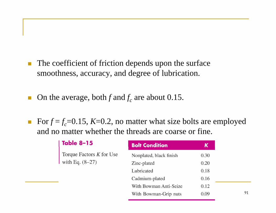
The coefficient of friction depends upon the surface p psmoothness, accuracy, and degree of lubrication.
On the average, both f and fc are about 0.15.
F f f 0 15 K 0 2 tt h t i b lt l dFor f = fc=0.15, K=0.2, no matter what size bolts are employed and no matter whether the threads are coarse or fine.
91
92
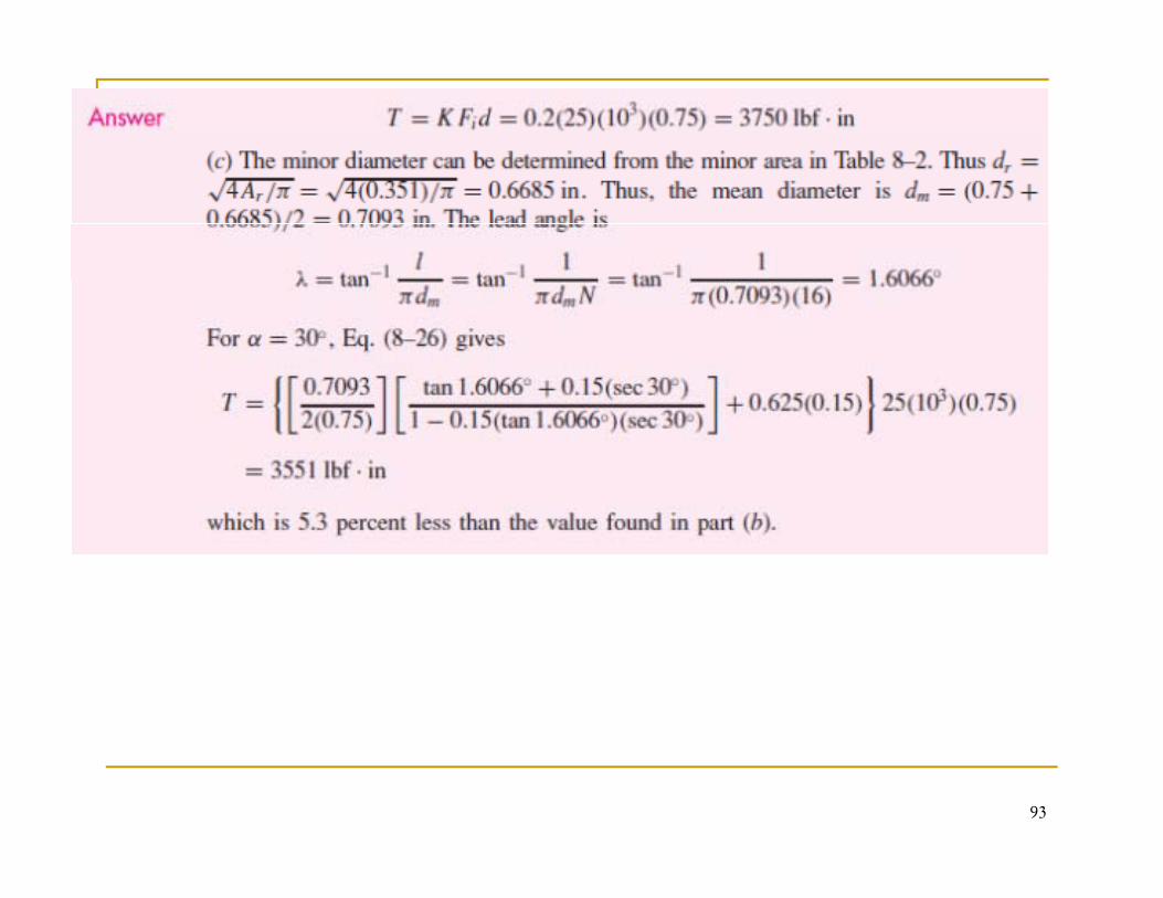
93
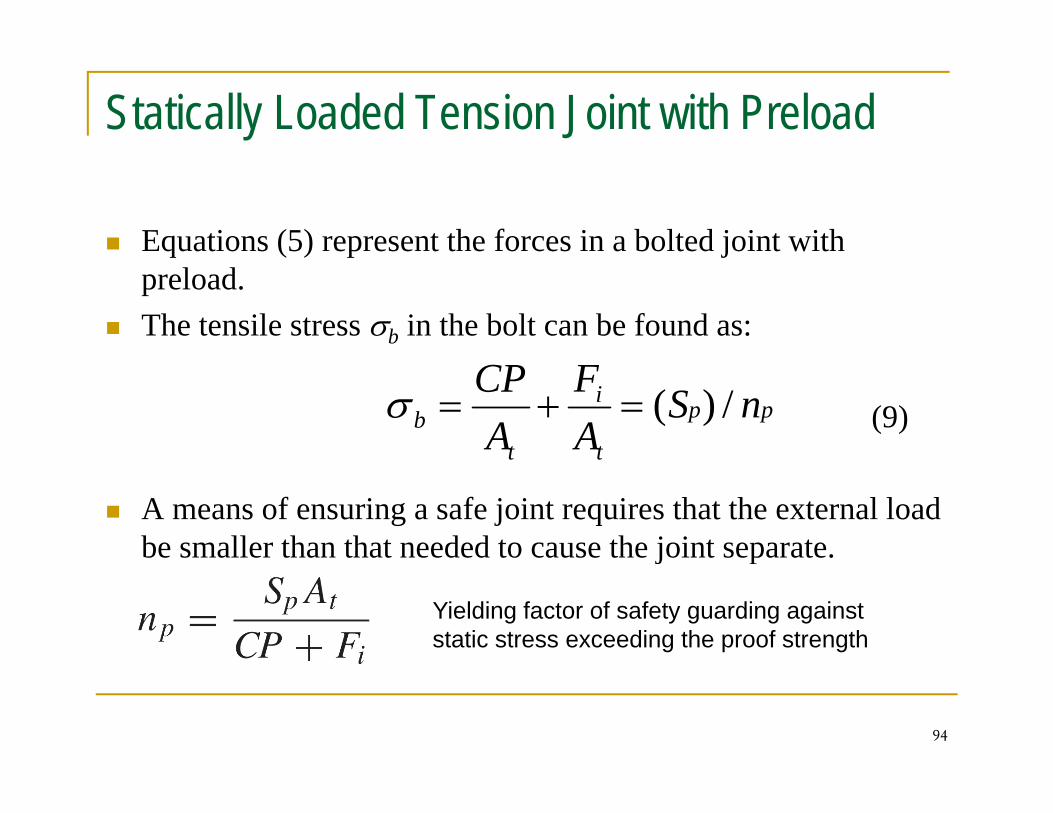
Statically Loaded Tension Joint with Preload
Equations (5) represent the forces in a bolted joint with q ( ) p jpreload.The tensile stress σb in the bolt can be found as:
(9)pp
t
i
tb nS
AF
ACP /)(=+=σ
A means of ensuring a safe joint requires that the external load be smaller than that needed to cause the joint separate.
tt
j p
Yielding factor of safety guarding against static stress exceeding the proof strength
94
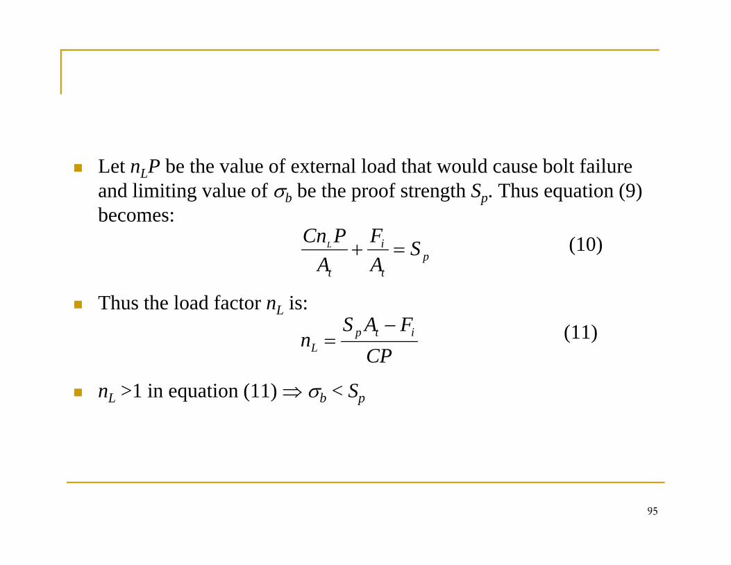
Let nLP be the value of external load that would cause bolt failure Land limiting value of σb be the proof strength Sp. Thus equation (9) becomes:
(10)i SFPCnL + (10)
Thus the load factor nL is:
pt
i
t
SAA
L =+
FAS (11)
n >1 in equation (11) ⇒ σ < S
CPFAS
n itpL
−=
nL >1 in equation (11) ⇒ σb < Sp
95
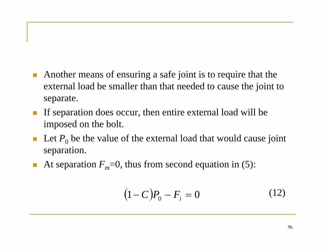
Another means of ensuring a safe joint is to require that the g j qexternal load be smaller than that needed to cause the joint to separate.If ti d th ti t l l d ill bIf separation does occur, then entire external load will be imposed on the bolt.Let P0 be the value of the external load that would cause joint et 0 be t e va ue o t e e te a oad t at wou d cause jo tseparation.At separation Fm=0, thus from second equation in (5):
(12)( ) 01 0 =−− iFPC
96
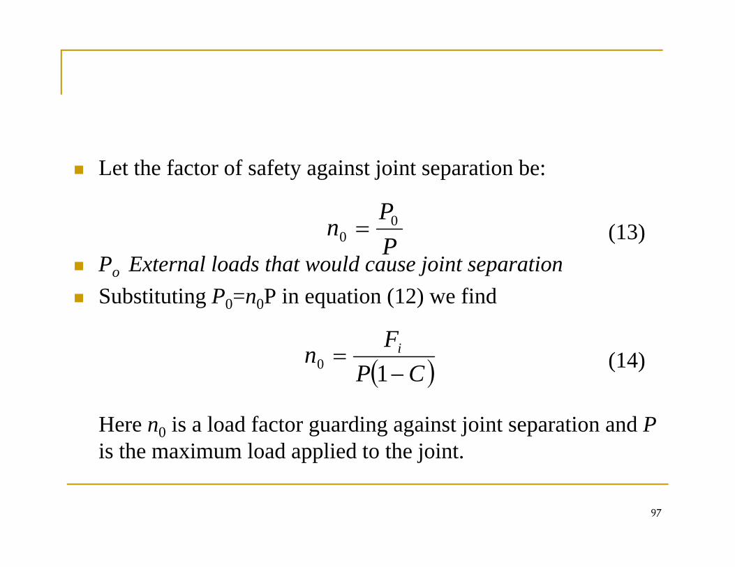
Let the factor of safety against joint separation be:y g j p
(13)PP
n 00 =
Po External loads that would cause joint separationSubstituting P0=n0P in equation (12) we find
P
(14)( )CPF
n i
−=
10
Here n0 is a load factor guarding against joint separation and Pis the maximum load applied to the joint.
97
pp j
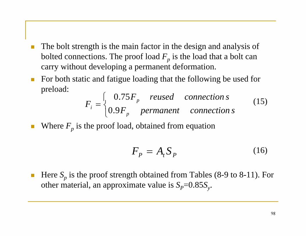
Th b l h i h i f i h d i d l i fThe bolt strength is the main factor in the design and analysis of bolted connections. The proof load Fp is the load that a bolt can carry without developing a permanent deformation. For both static and fatigue loading that the following be used for preload:
(15)⎨⎧ sconnectionreusedF
F p75.0 (15)
Where Fp is the proof load, obtained from equation⎩⎨=
sconnectionpermanentFF
pi 9.0
(16)PtP SAF =
Here Sp is the proof strength obtained from Tables (8-9 to 8-11). For other material, an approximate value is SP=0.85Sy.
98
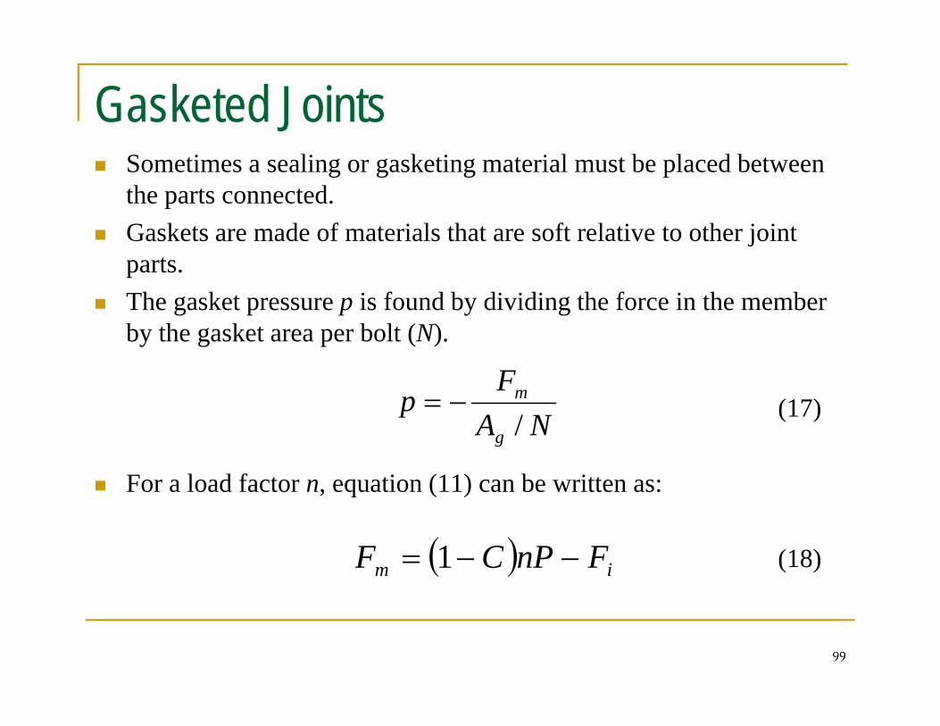
Gasketed JointsSometimes a sealing or gasketing material must be placed between the parts connected.G k t d f t i l th t ft l ti t th j i tGaskets are made of materials that are soft relative to other joint parts.The gasket pressure p is found by dividing the force in the member by the gasket area per bolt (N).
(17)F
p m−= (17)
For a load factor n, equation (11) can be written as:
NAp
g /
(18)( ) im FnPCF −−= 1
99
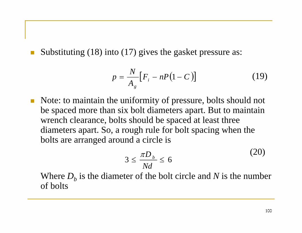
Substituting (18) into (17) gives the gasket pressure as:
( )[ ]N (19)
Note: to maintain the uniformity of pressure bolts should not
( )[ ]CnPFANp i
g
−−= 1
Note: to maintain the uniformity of pressure, bolts should not be spaced more than six bolt diameters apart. But to maintain wrench clearance, bolts should be spaced at least three diameters apart So a rough rule for bolt spacing when thediameters apart. So, a rough rule for bolt spacing when the bolts are arranged around a circle is
(20)63 ≤≤
D bπ
Where Db is the diameter of the bolt circle and N is the number of bolts
63 ≤≤Nd
100
Fatigue LoadingMost of the time, the type of fatigue loading encountered inthe analysis of bolted joints is one in which the externallyapplied load fluctuates between zero and some maximum forceP.This would be the situation in a pressure cylinder for exampleThis would be the situation in a pressure cylinder, for example where a pressure either exists or does not exist For such cases:
Fmax=Fb and Fmin=Fi
Thus, Fa=( Fmax - Fmin)/2=(Fb - Fi)/2
101
Dividing this by At yields the alternating component of the bolt stress:
(21)( ) iiib CPFFCPFF −+− (21)
The mean stress is equal to the alternating component plus the
( )tt
ii
t
iba A
CPA
FFCPA
FF222
=+
==σ
q g p pminimum stress, σi = Fi / At
(22)iFCP+=σ (22)
On the designer’s fatigue diagram as shown in figure 8-20, the
ttm AA
+=2
σ
g g g gload line is:
(23)iσσσ +=
102
(23)iam σσσ +
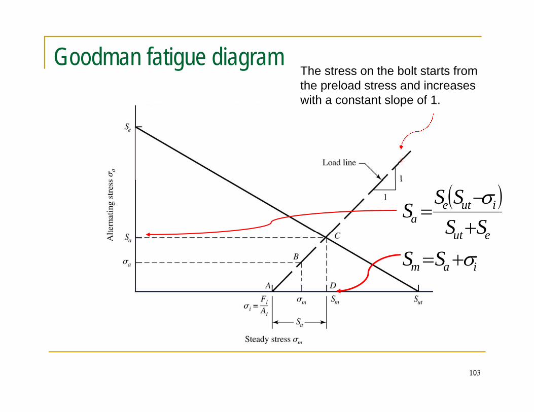
Goodman fatigue diagramThe stress on the bolt starts from the preload stress and increases with a constant slope of 1.
( )t
iutea SS
SSS
σ+−
=
iam
eut
SSSS
σ+=+
103
The strength components Sa and Sm of the fatigue failure locus. g p a m gUsing Goodman failure criteria:
(24)1=+ ma SS(24)
Substitute equation (23) with σ as S for into (24) we have:
1=+ute SS
(25)( )
eut
iutea SS
SSS
σ+−
=
In this section, Kf is applied for both σa and σm
iam SS σ+=
104
, f pp a m
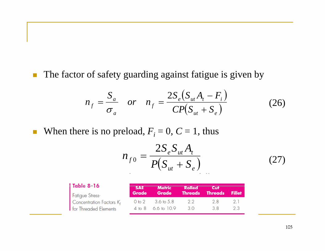
The factor of safety guarding against fatigue is given by y g g g g g y
(26)( )( )
itutef
af SSCP
FASSnor
Sn
+−
==2
σ
When there is no preload, Fi = 0, C = 1, thus
( )euta SSCP +σ
(27)( )eut
tutef SSP
ASSn
+=
20
105
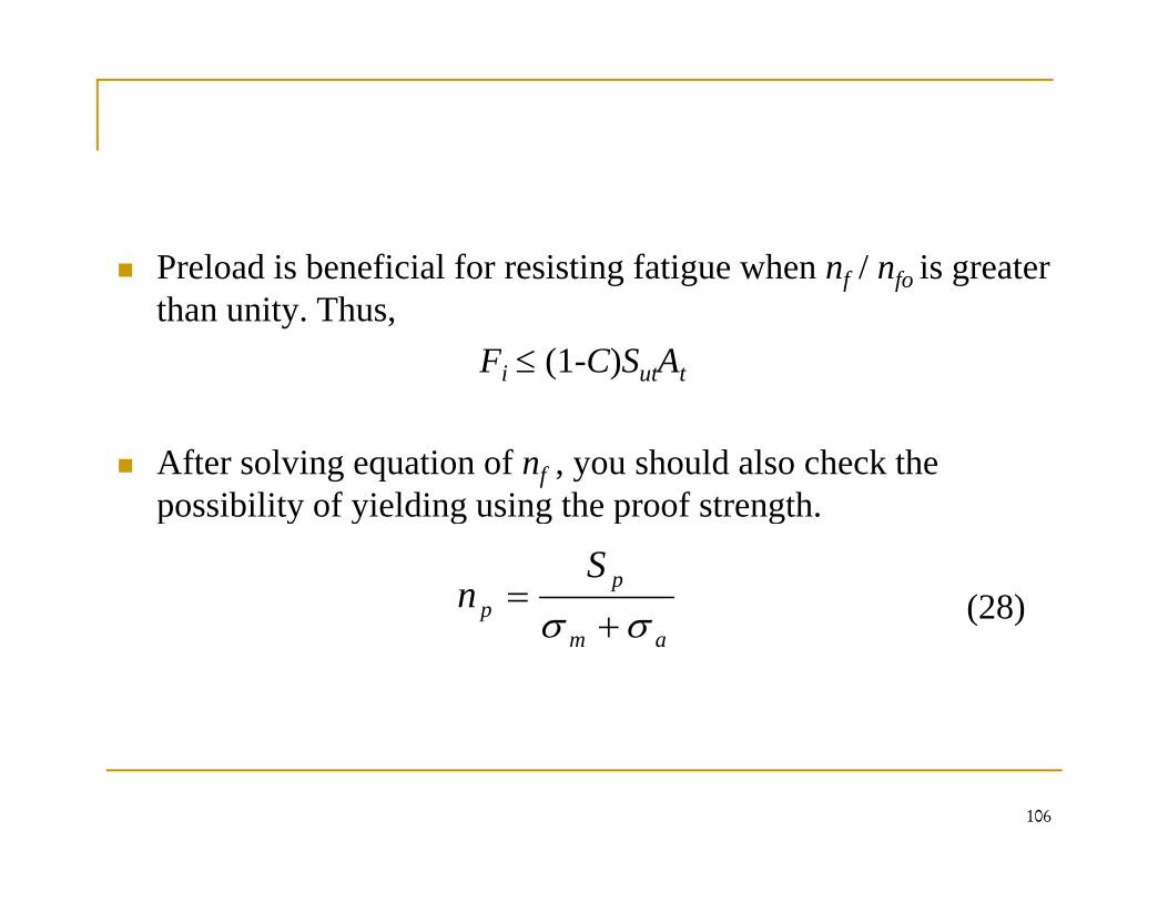
Preload is beneficial for resisting fatigue when nf / nfo is greater g g f fo gthan unity. Thus,
Fi ≤ (1-C)SutAt
After solving equation of nf , you should also check the possibility of yielding using the proof strengthpossibility of yielding using the proof strength.
(28)p
p
Sn
σσ += ( )
am σσ +
106
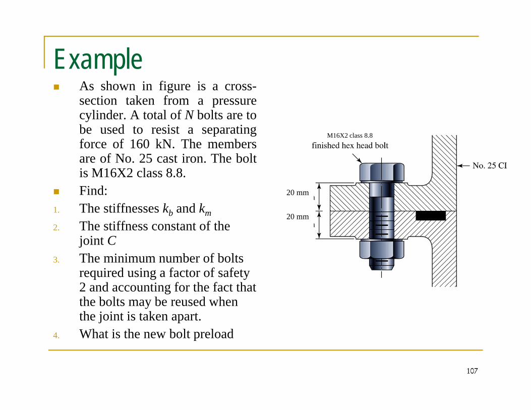
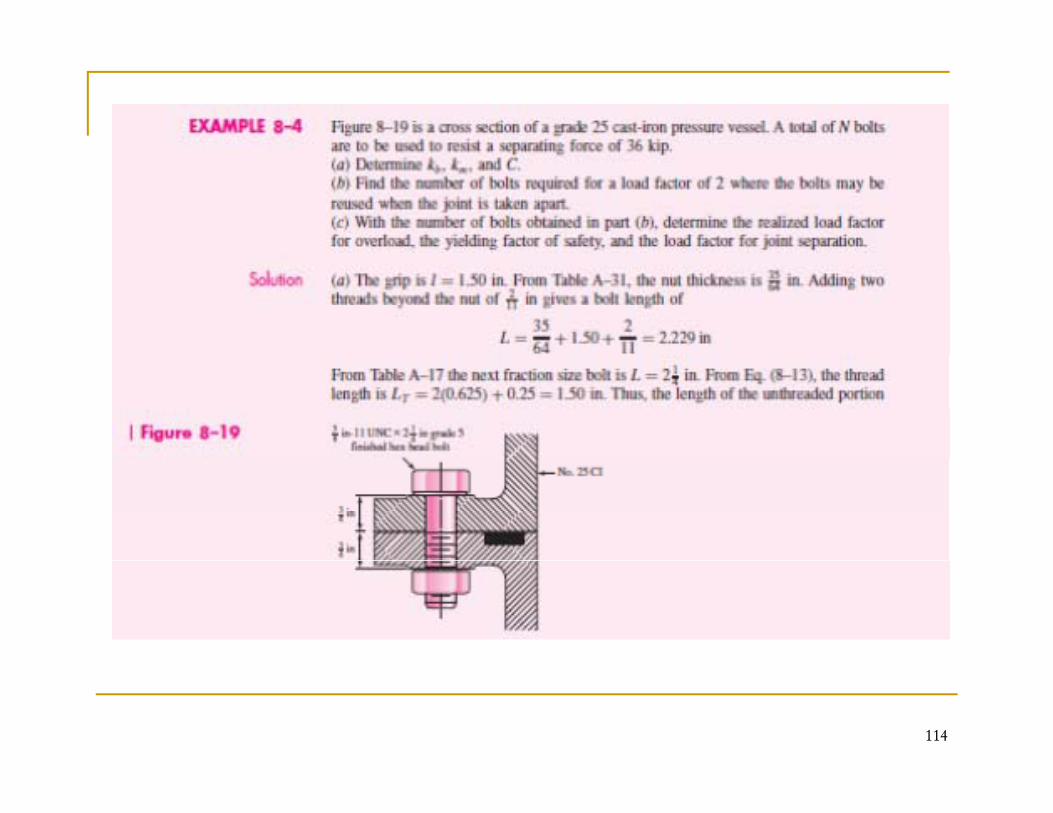
ExampleAs shown in figure is a cross-section taken from a pressurecylinder. A total of N bolts are tobe sed to resist a separatingbe used to resist a separatingforce of 160 kN. The membersare of No. 25 cast iron. The boltis M16X2 class 8.8.
M16X2 class 8.8
Find:1. The stiffnesses kb and km2. The stiffness constant of the
20 mm
20 mm
joint C3. The minimum number of bolts
required using a factor of safety 2 d i f h f h2 and accounting for the fact that the bolts may be reused when the joint is taken apart.
4 What is the new bolt preload
107
4. What is the new bolt preload
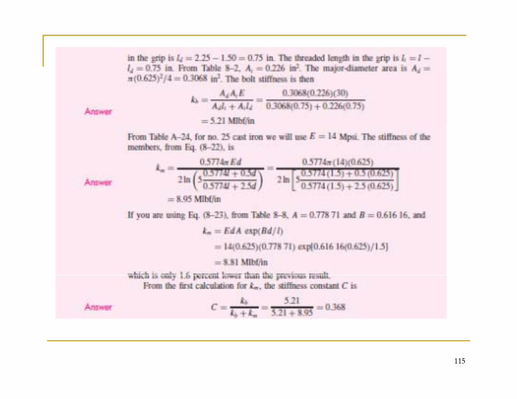
Solution: 1. Finding the stiffnesses kb and km
The stiffness of the bolt kb is:F M16X2 i l j di D d 16From M16X2 ⇒ nominal major diameter D = d = 16 mm, Pitch P = 2 mmFrom table A-31 with M16 ⇒ H = 14.8 mm for Regular gHexagonal head.The total length of the bolt L = LG + H + (2 threads after the nuts)nuts)Thus, L = 2(20) + 14.8 + 2(P) = 40+14.8+2(2) = 58.8 mm
From table A-17, choose L=60 mm
108
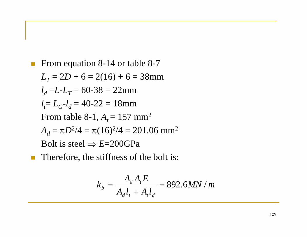
From equation 8-14 or table 8-7L 2D 6 2(16) 6 38LT = 2D + 6 = 2(16) + 6 = 38mmld =L-LT = 60-38 = 22mml = L l = 40 22 = 18mmlt= LG-ld = 40-22 = 18mmFrom table 8-1, At = 157 mm2
Ad = πD2/4 = π(16)2/4 = 201.06 mm2d ( )
Bolt is steel ⇒ E=200GPaTherefore, the stiffness of the bolt is:
mMNlAlA
EAAk
dd
tdb /6.892=
+=
109
lAlA dttd +
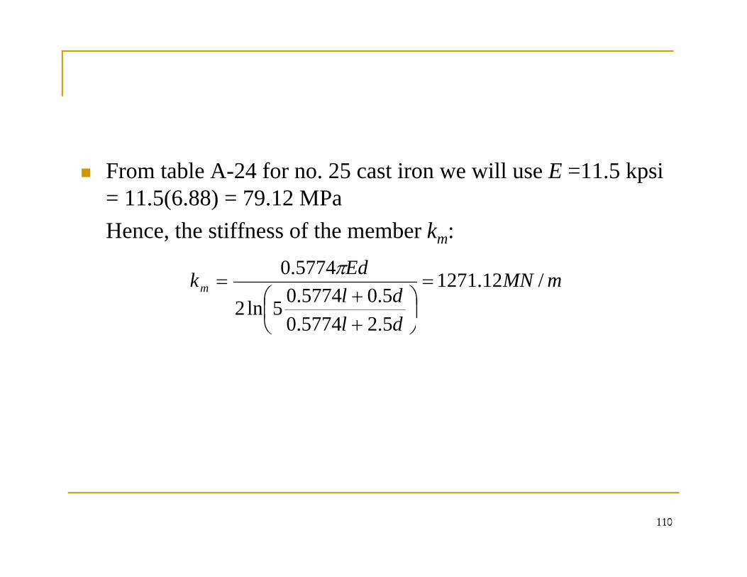
From table A-24 for no. 25 cast iron we will use E =11.5 kpsi p= 11.5(6.88) = 79.12 MPaHence, the stiffness of the member km:
mMN
dldl
Edkm /12.1271
52577405.05774.05ln2
5774.0=
⎟⎠⎞
⎜⎝⎛
++
=π
dl 5.25774.0 ⎠⎝ +
110
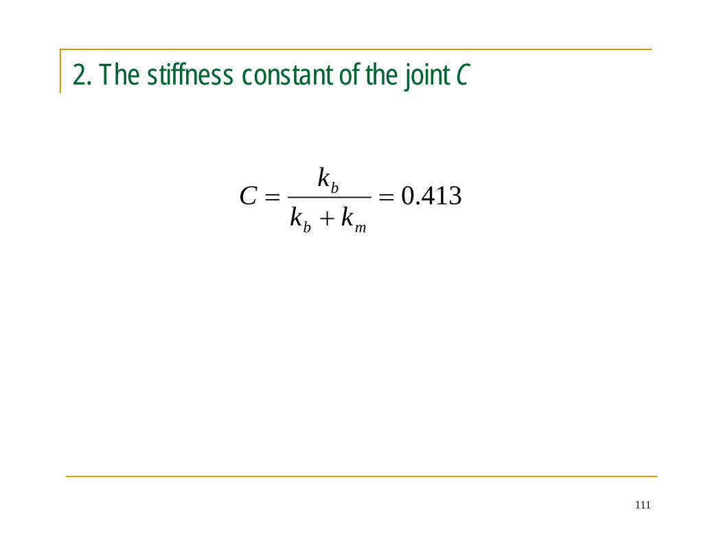
2. The stiffness constant of the joint C
k413.0=
+=
mb
b
kkk
C
111
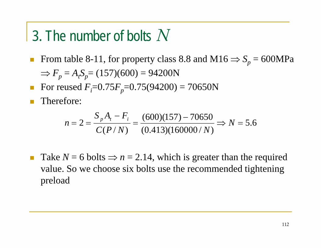
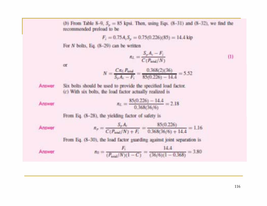
3. The number of bolts NFrom table 8-11, for property class 8.8 and M16 ⇒ Sp = 600MPa⇒ Fp = AtSp= (157)(600) = 94200Np t p ( )( )For reused Fi=0.75Fp=0.75(94200) = 70650NTherefore:
6.5)/160000)(413.0(
70650)157)(600()/(
2 =⇒−
=−
== NNNPC
FASn itp
Take N = 6 bolts ⇒ n = 2.14, which is greater than the required value. So we choose six bolts use the recommended tighteningvalue. So we choose six bolts use the recommended tightening preload
112
4. The new bolt preload
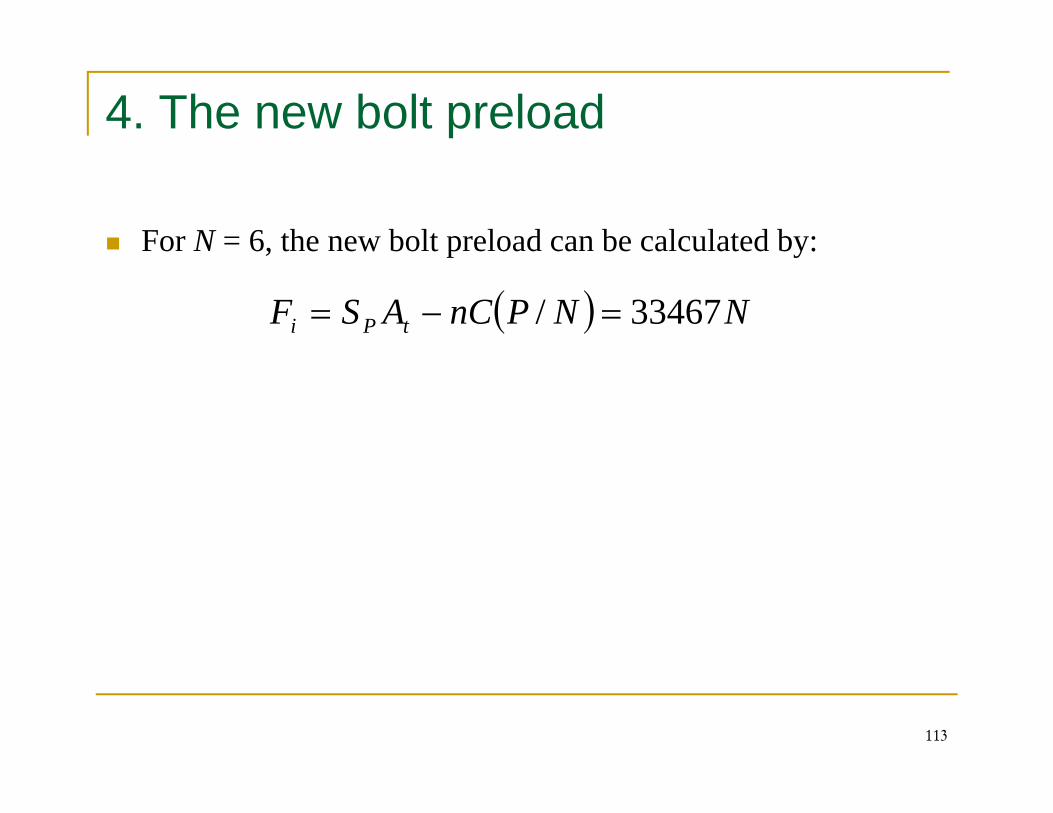
For N = 6, the new bolt preload can be calculated by:, p y
( ) NNPnCASF tPi 33467/ =−=
113
114
115
116
Example
An M30X3.5 ISO 8.8 bolt is used in a joint at recommendedjpreload and the joint is subject to a repeated tensile fatigueload of P=80kN per bolt. The joint constant is C=0.33. Findthe load factors and the factor of safety guarding against athe load factors and the factor of safety guarding against afatigue failure based on the Goodman theory.
117
Solution
From table 8-1From table 8 1D = d = 30 mm ⇒ P=3.5 mm, At = 561mm2
From table 8-11 For 8.8 class and M30X3.5 ⇒ Sp = 600 MPa, Sy = 660 MPa, Sut = 830 MPaFrom table 8-17For ISO 8.8 ⇒ Se=129 MPa
118
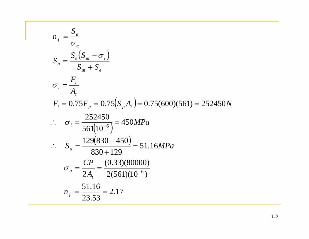
= af
Sn
σ( )
+−
=eut
iutea
a
SSSS
Sσ
σ
( ) 252450)561)(600(750750750 ====
=t
ii
NASFFAF
σ
( )
( ) 45010561
252450
252450)561)(600(75.075.075.0
6 ==∴
====
−i
tppi
MPa
NASFF
σ
( )
)80000)(33.0(
16.51129830
450830129=
+−
=∴ a
CP
MPaS
17.2323
16.51)10)(561(2)80000)(33.0(
2 6
==
== −
f
ta
n
ACPσ
119
53.23f
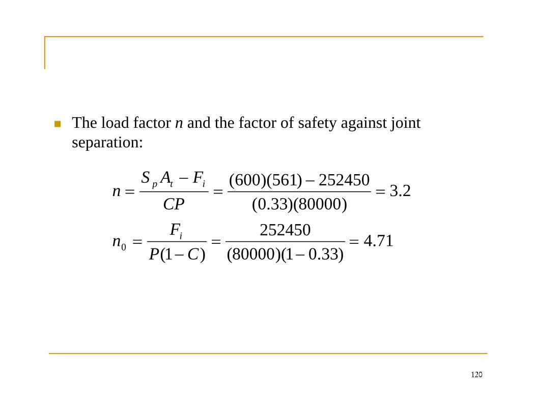
The load factor n and the factor of safety against joint y g jseparation:
252450)561)(600( −− FAS i
252450
2.3)80000)(33.0(
252450)561)(600(=
−==
FCP
FASn
i
itp
71.4)33.01)(80000(
252450)1(0 =
−=
−=
CPF
n i
120
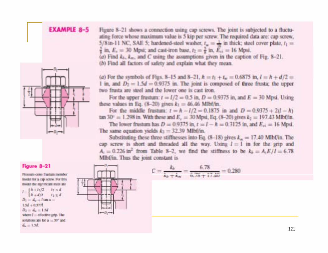
121
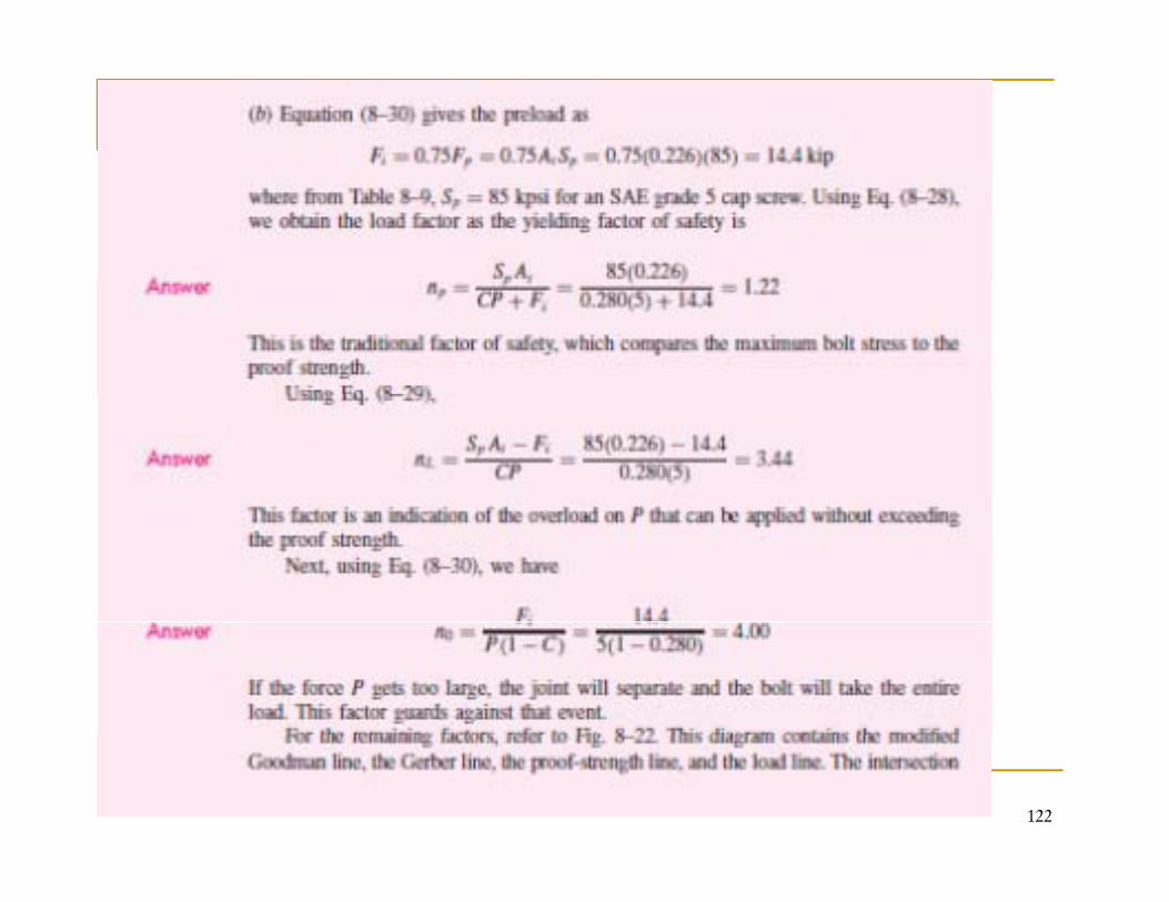
122
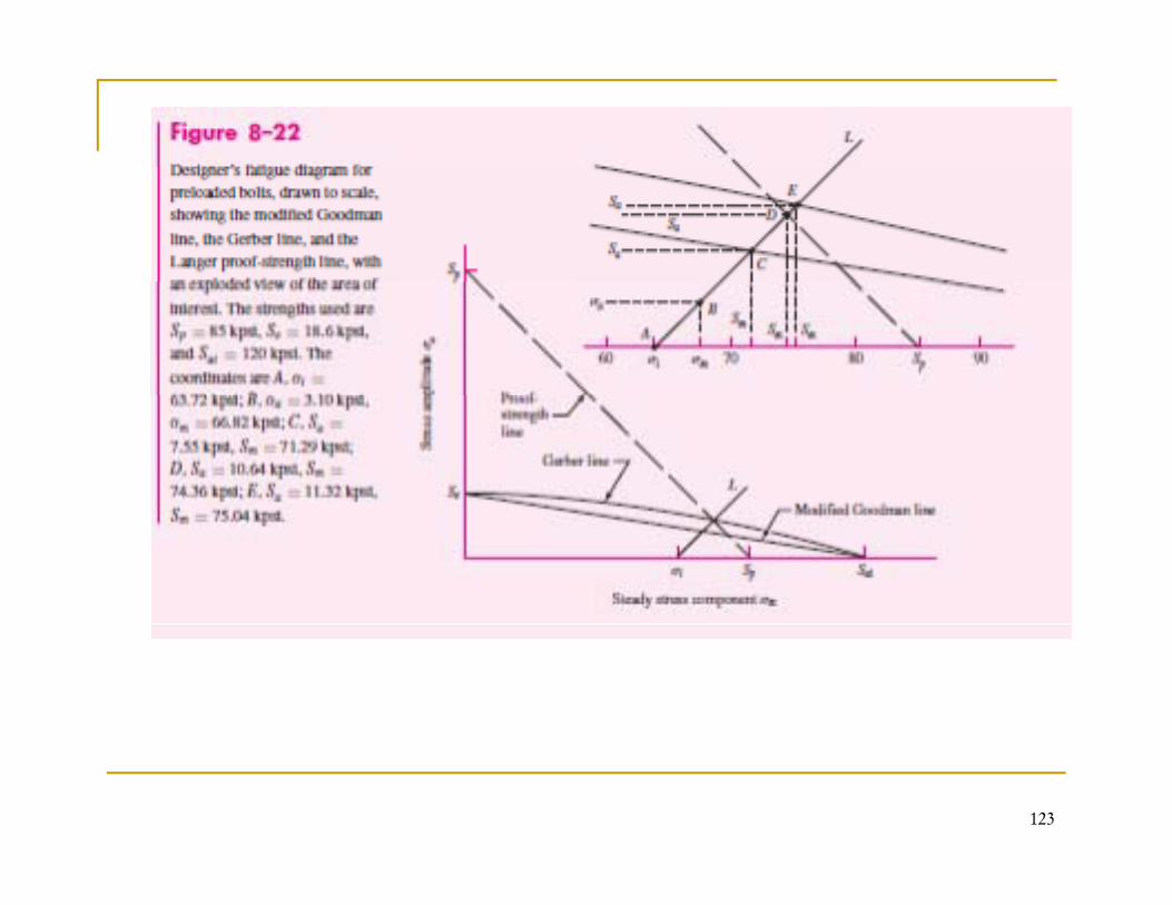
123
124
125
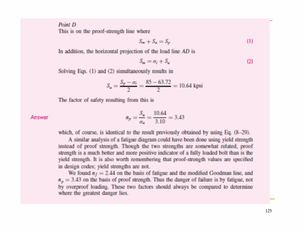
Shear Joints
Riveted and bolted joints loaded in sheer are treated exactly j yalike in design and analysis. In days when driving hot rivets was a common structural j i i th d th d i i d th t th i t fill djoining method, the driving ensured that the rivets filled every hole completely and, upon cooling, providing a clamping preload. This kind of rivet pattern can shear a sheer load.
126
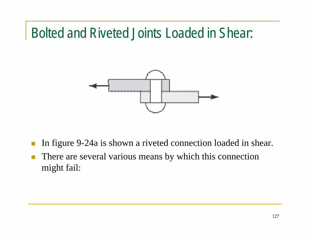
Bolted and Riveted Joints Loaded in Shear:
In figure 9-24a is shown a riveted connection loaded in shear.There are several various means by which this connection
i h f ilmight fail:
127
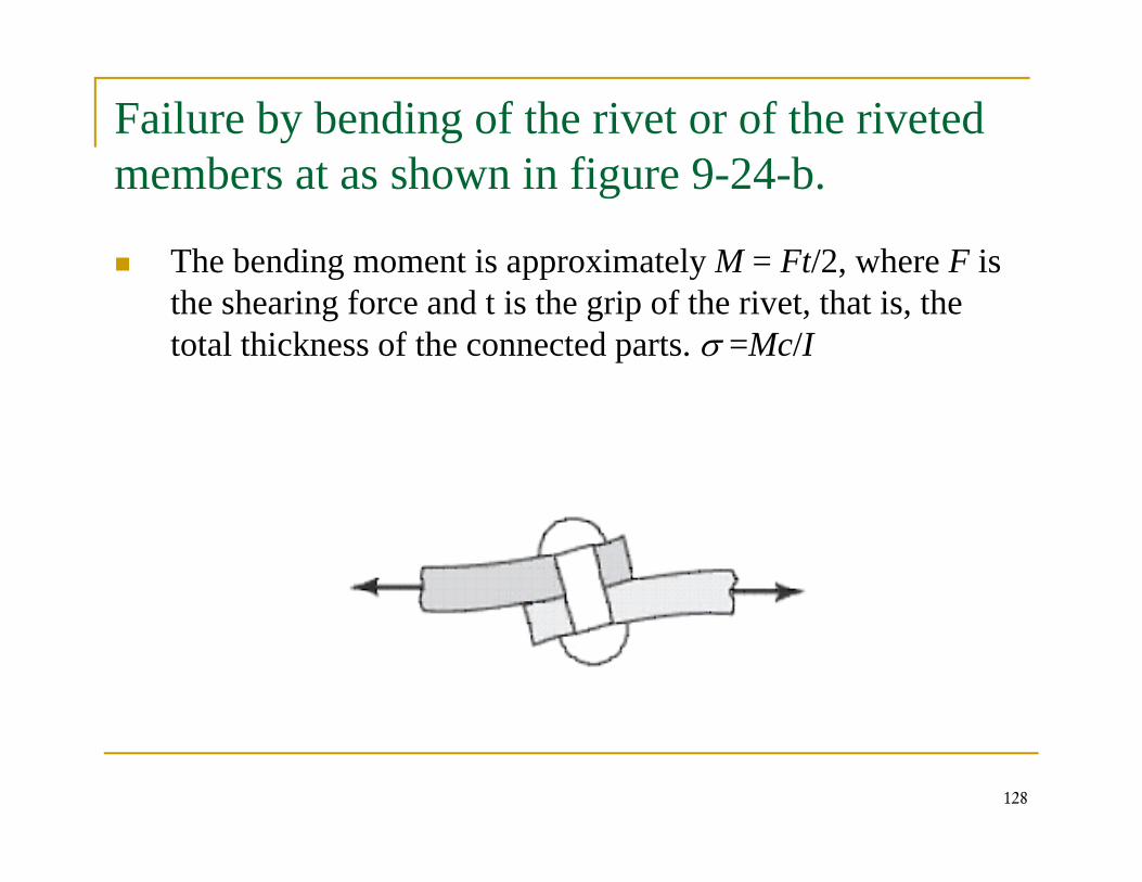
Failure by bending of the rivet or of the riveted b t h i fi 9 24 bmembers at as shown in figure 9-24-b.
The bending moment is approximately M = Ft/2, where F is g pp y ,the shearing force and t is the grip of the rivet, that is, the total thickness of the connected parts. σ =Mc/I
128
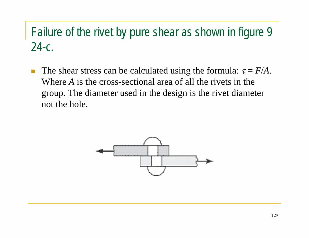
Failure of the rivet by pure shear as shown in figure 9 2424-c.
The shear stress can be calculated using the formula: τ = F/A. gWhere A is the cross-sectional area of all the rivets in the group. The diameter used in the design is the rivet diameter not the holenot the hole.
129
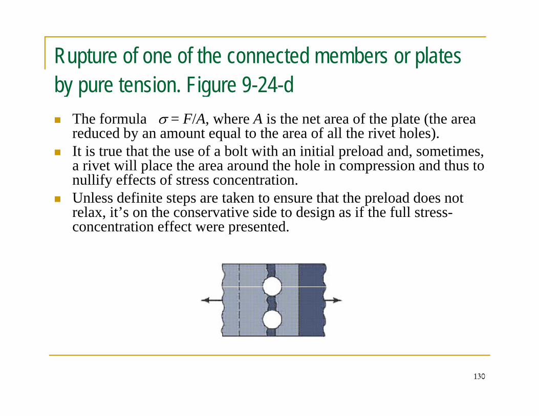
Rupture of one of the connected members or plates b t i Fi 9 24 dby pure tension. Figure 9-24-d
The formula σ = F/A, where A is the net area of the plate (the area d d b t l t th f ll th i t h l )reduced by an amount equal to the area of all the rivet holes).
It is true that the use of a bolt with an initial preload and, sometimes, a rivet will place the area around the hole in compression and thus to nullify effects of stress concentrationnullify effects of stress concentration.Unless definite steps are taken to ensure that the preload does not relax, it’s on the conservative side to design as if the full stress-concentration effect were presented. p
130
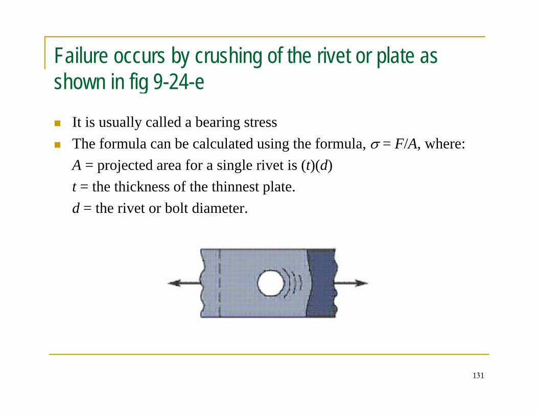
Failure occurs by crushing of the rivet or plate as h i fi 9 24shown in fig 9-24-e
It is usually called a bearing stressy gThe formula can be calculated using the formula, σ = F/A, where: A = projected area for a single rivet is (t)(d)
h hi k f h hi lt = the thickness of the thinnest plate.d = the rivet or bolt diameter.
131
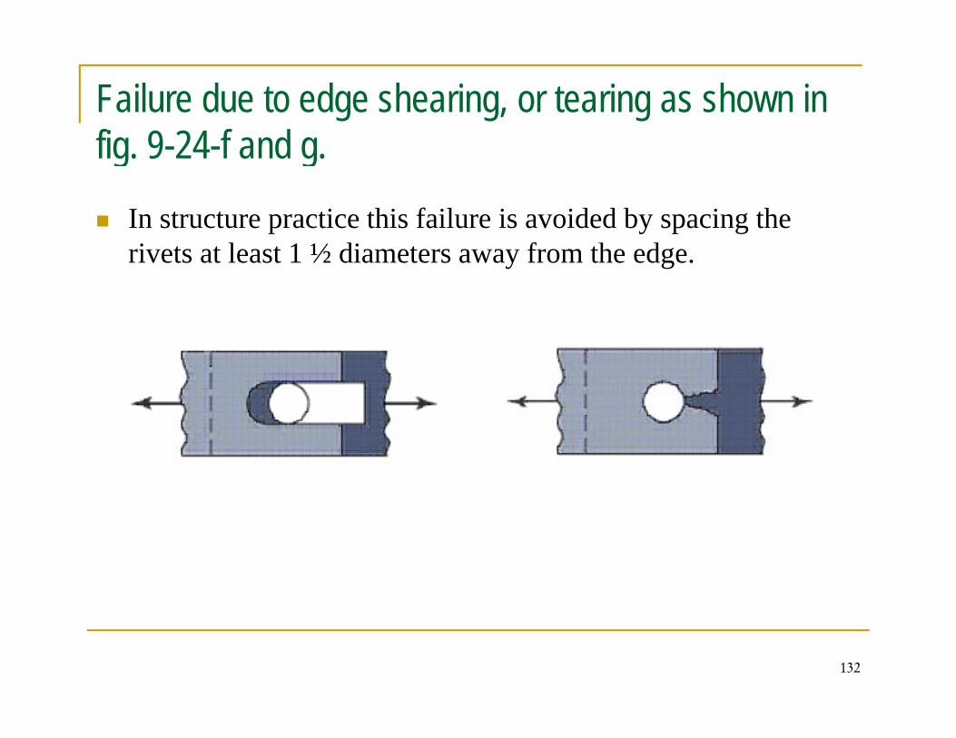
Failure due to edge shearing, or tearing as shown in fi 9 24 f d fig. 9-24-f and g.
In structure practice this failure is avoided by spacing the p y p grivets at least 1 ½ diameters away from the edge.
132
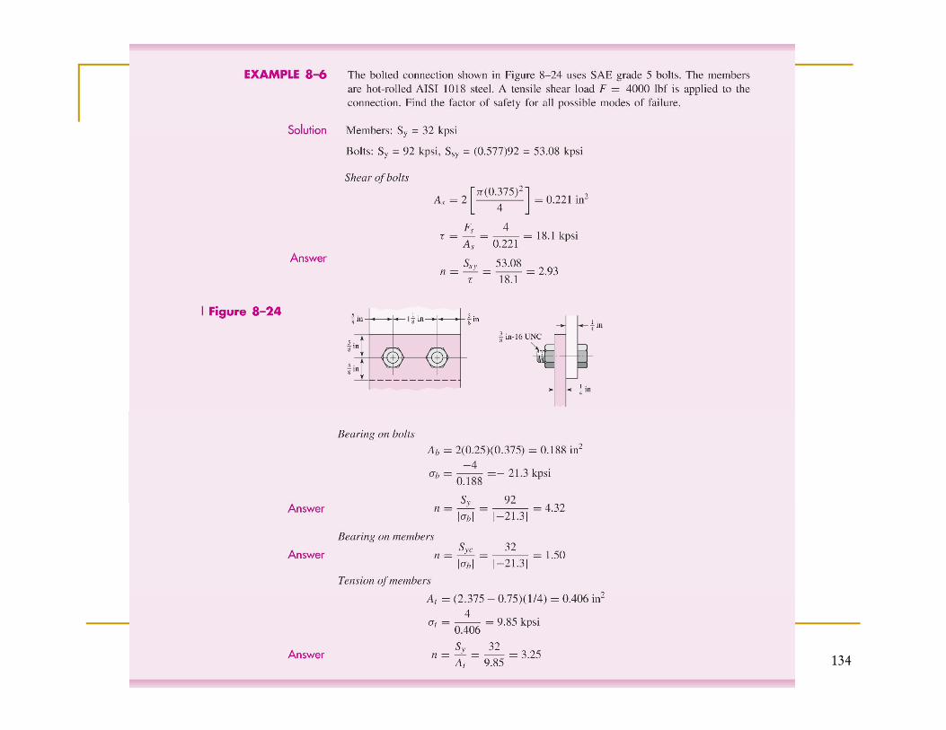
In structure design it is customary to select in advance the g ynumber of rivets and their diameters and spacing.
The strength is then determined for each method of failure.
If th l l t d t th i t ti f t h i dIf the calculated strength is not satisfactory, a change is made in the diameter, spacing, or number of rivets used to bring the strength in line with expected loading conditions.
133
134
135
136
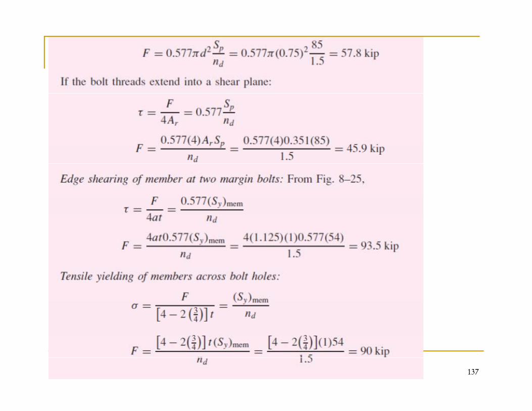
137
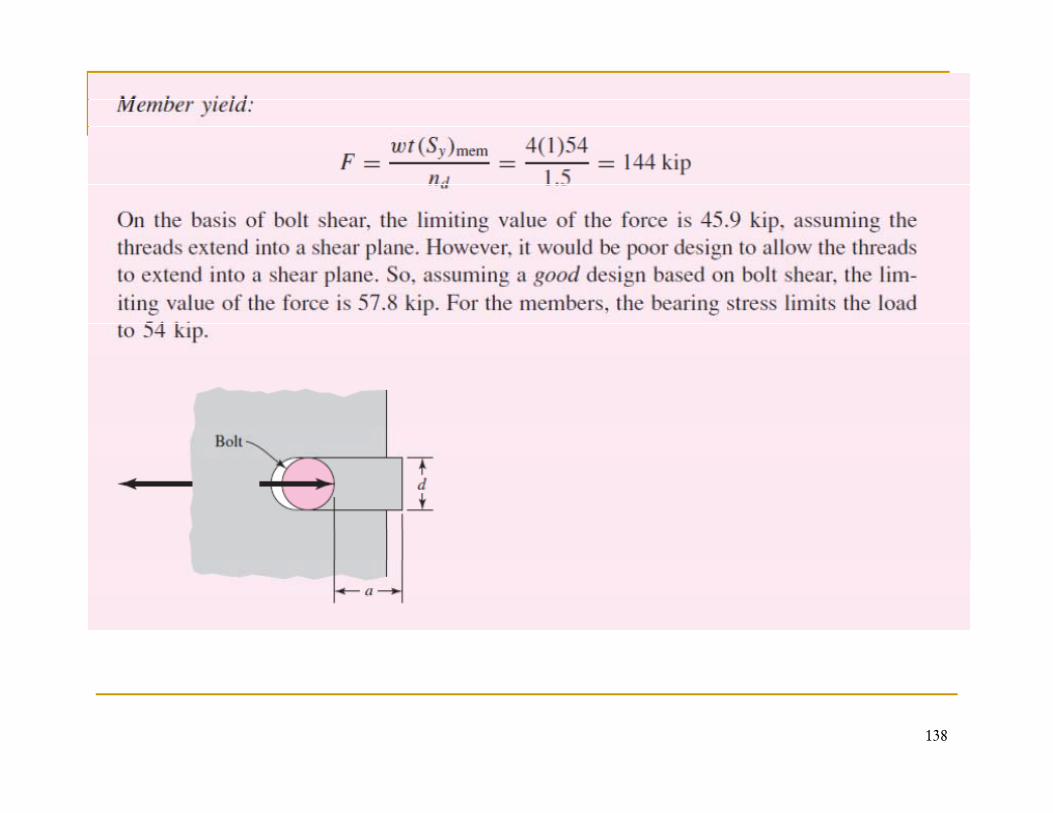
138
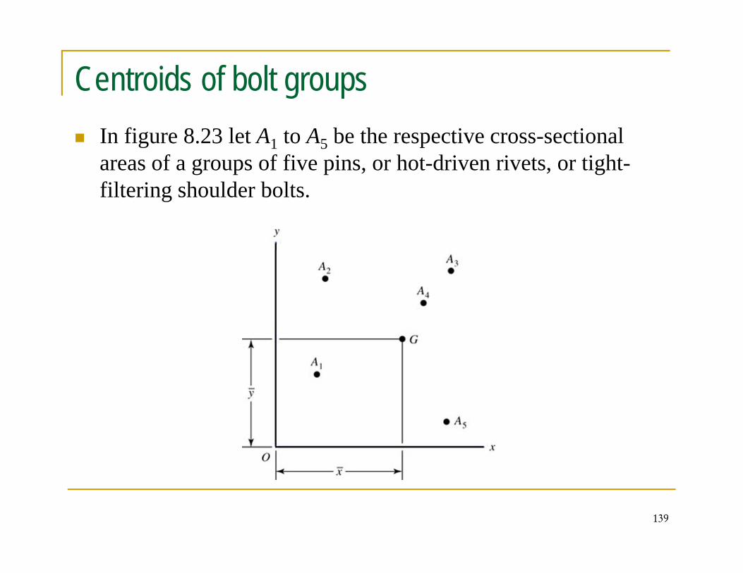
Centroids of bolt groupsIn figure 8.23 let A1 to A5 be the respective cross-sectional areas of a groups of five pins, or hot-driven rivets, or tight-filtering shoulder bolts.
139
Under this assumption the rotational pivot point lies at the p p pcentroid of the cross-sectional area pattern of the pins, rivets, or bolts. U i t ti th t id G b f d bUsing static, the centroid G can be found by:
(8-49)∑∑5
1
5
1iiii yAxA
(8-49)∑∑
== 5
1
15
1
1
ii Ayand
Ax
140
Shear of bolts and rivets due to eccentric loading
An example of eccentric loading of fasteners is shown inAn example of eccentric loading of fasteners is shown in figure 8-24
The beam is fastened to vertical numbers at the ends with specially prepared load-sharing bolts.
The centers of the bolts at the left end of the beam are drawn to a large scale in figure (8-24-c).
141
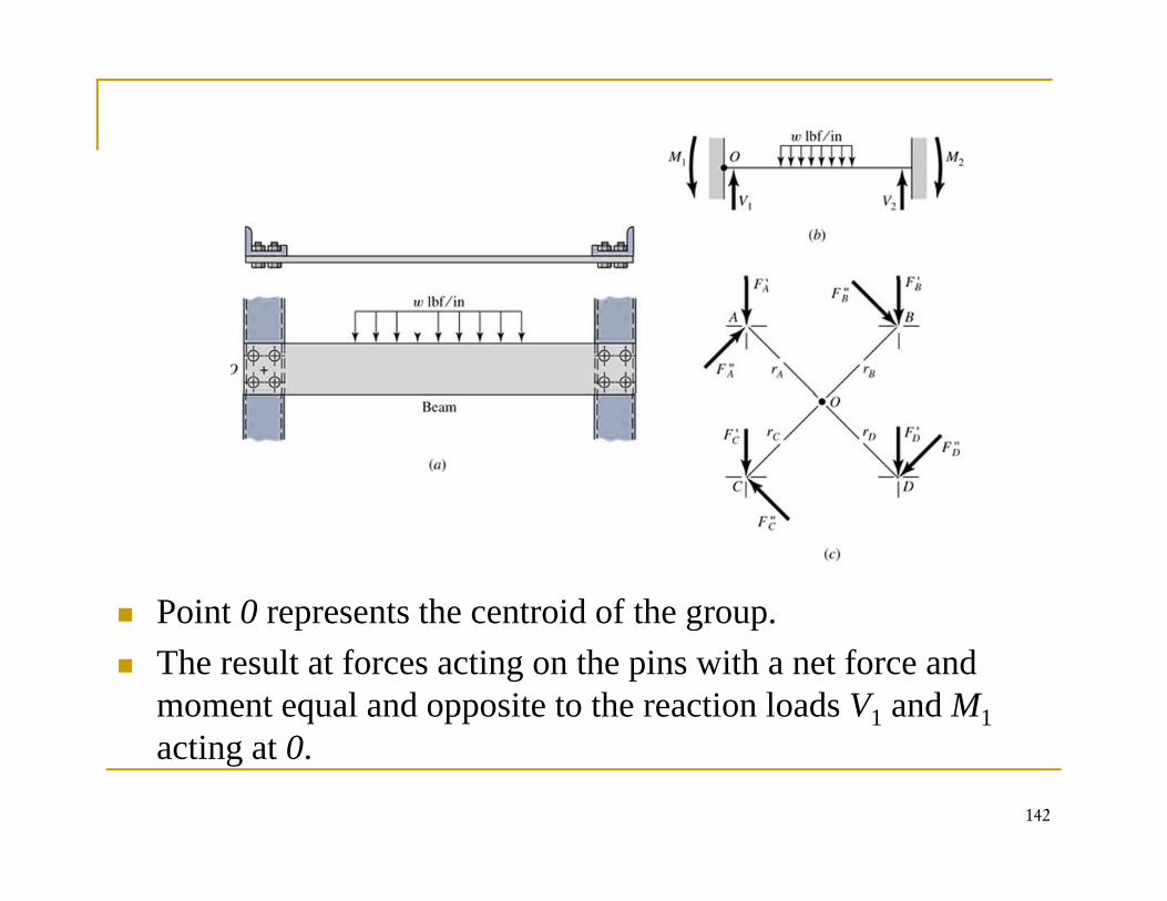
Point 0 represents the centroid of the group.Point 0 represents the centroid of the group. The result at forces acting on the pins with a net force and moment equal and opposite to the reaction loads V1 and M1
i
142
acting at 0.
The total load taken by each bolt can be found by the following 3 steps1. Each bolt takes F′= V1/ n, 1 ,
Where n = number of bolts in the group. F′ = direct load or primary shear.
2. The moment load or secondary shear: It is the additional load on each bolt due to the moment M. If r r r etc are the radial distances from the centroid to the centerIf rA, rB, rC, etc, are the radial distances from the centroid to the center of each bolt. Thus,
(1)...""" +++= CCBBAA rFrFrFM
Where F” is the moment load
CCBBAA
143
Therefore(2)CBA
rF
rF
rF """
==
Solving equations (2) and (2) simultaneously, we obtain:
CBA rrr
M(8.50)...222
1"
+++=
CBA
nn rrr
rMF
Where n refers to the particular bolt whose load is to be found
3 Find the resultant load of both vertical and moment loads3. Find the resultant load of both vertical and moment loads
144
Example
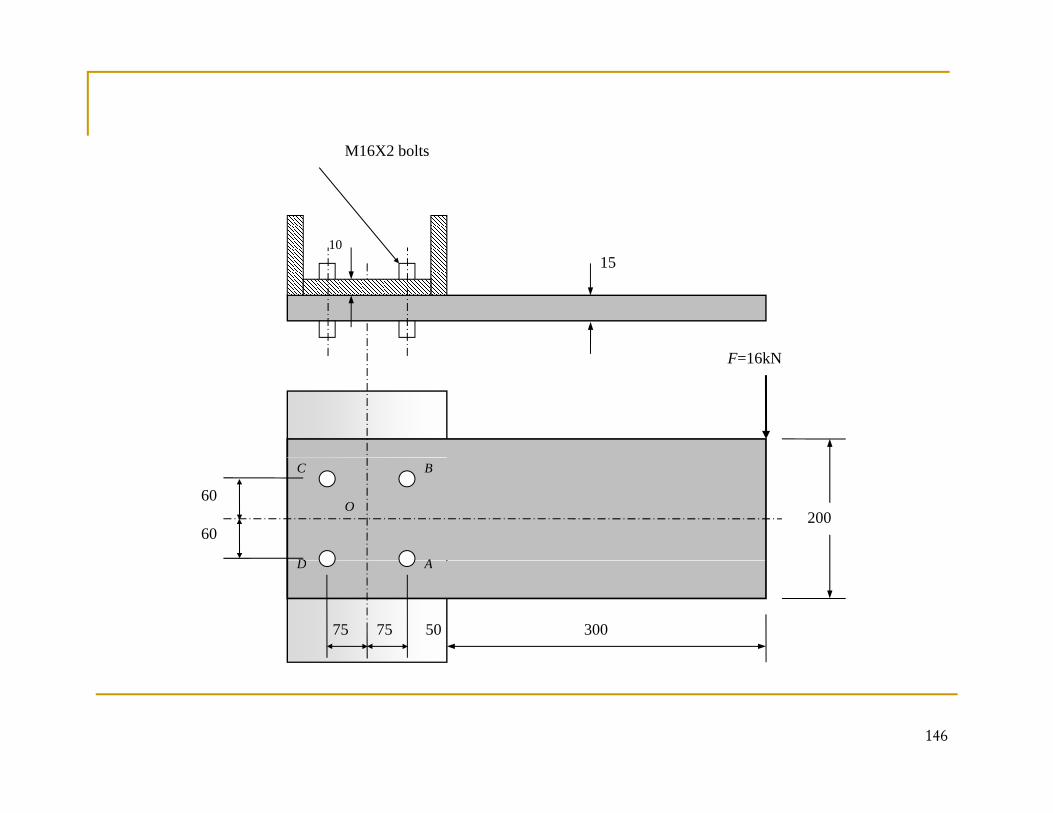
As shown in figure a 15X200 mm rectangular steel bar il d 250 l h l i f b l Ocantilevered to a 250 mm steel channel using four bolts. On
the basis of the external load of 16kN, find: a) The resultant load on each bolta) The resultant load on each boltb) The maximum bolt shear stressc) The maximum bearing stressd) The bending stress through bolts A and B.
145
M16X2 boltsM16X2 bolts
10
F 16kN
15
F=16kN
60
60
O
B
A
C
D
200
300
AD
75 75 50
146
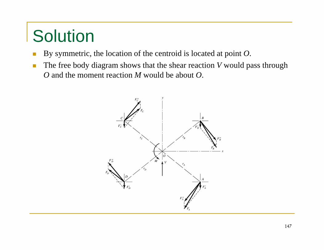
SolutionBy symmetric, the location of the centroid is located at point O.The free body diagram shows that the shear reaction V would pass through O and the moment reaction M would be about O.
147
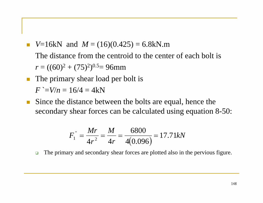
V=16kN and M = (16)(0.425) = 6.8kN.mThe distance from the centroid to the center of each bolt isr = ((60)2 + (75)2)0.5= 96mmThe primary shear load per bolt isF ` V/ 16/4 4kNF =V/n = 16/4 = 4kNSince the distance between the bolts are equal, hence the secondary shear forces can be calculated using equation 8-50:y g q
( ) kNMMrF 71.1709604
680044 2
"1 ====
The primary and secondary shear forces are plotted also in the pervious figure.
( )rr 096.0444 2
148
a) The result load on each bolt can be found using the parallelogram rule
Therefore, the resultant load on each bolts are:,
FA = FB =21.0 kNFC = FD =13.8 kN
149

b) The maximum Load on each bolt
Bolts A and B carries the largest shear load, therefore our gcalculation will be for bolts A and BWhere the shear acts on the bolt?To answer this question we need to find first the length of theTo answer this question, we need to find first the length of the bolt:L=LG + H + 2PLG = 15+10 = 25mmH: From table A-31, H=14.8mm, P = 2P = 2 ∴ L = (15+10) + (14.8) + 2(2) = 43.8 mmFrom table A-17, L= 45mm
150
From equation 8-14, LT = 2D+6 = 2(16)+6 = 38mmq , T ( )∴ the unthreaded length ld= L- LT = 45-38=7mm∴ the threaded length lt=LG-ld=25-7=18mmYou can see now that the unthreaded length is less than the thickness of the plate (15 thickness). Therefore the shear stress area is based on the threaded section and hence will bearea is based on the threaded section and hence will be represented by the miner diameter for the bolt: from table 8-1, Ar =144mm2.∴ τ =F/Ar = 21000/144(10-6) = 145.83MPa
151
c) The maximum bearing stress:
From the figure we can see that the channel is thinner than the gbar, so the largest bearing stress is due to the pressing of the bolt against the channel web:
MPatdF
AF A
b 25.131)16)(10(
21000====σ
tdAb )16)(10(
152
d) The bending stress through bolts A and B.
( )mNM .5600)50300(16
2
=+=
( )mm
AdIII holesbar
)10(26.8)16)(15()60(12
)16(15212
)200(15
2
46233
2
=⎥⎦
⎤⎢⎣
⎡+−
=+−=
MPaI
Mc 8.67)10(268)100(5600
)())(()(1212
6 ===
⎥⎦
⎢⎣
σI )10(26.8
153
Keys and Pins
Keys and pins are used on shafts to secure rotating elements, y p g ,such as gears, pulleys, or other wheels.
Keys are used to enable the transmission of torque from the shaft to the shaft-support element.
Pins are used for axial positioning and for the transfer of torque or thrust or both.
154
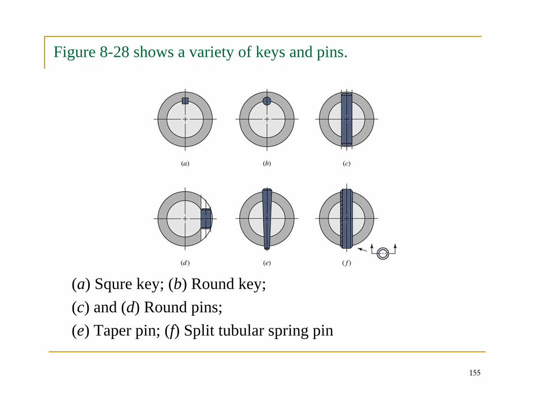
Figure 8-28 shows a variety of keys and pins.
(a) Squre key; (b) Round key;(a) Squre key; (b) Round key; (c) and (d) Round pins; (e) Taper pin; (f) Split tubular spring pin
155
( ) p p ; (f) p p g p

![Untitled-1 [arthomson.com] · Thermocouples & RTD's aEOTEMP INSTRUMENTS Screw Cover n Head Head Transmitter Table@ Table@ (optional) Threaded Connection Table© Stem Thermocouple](https://static.fdocuments.in/doc/165x107/6014c49c265f0a020a15f8c5/untitled-1-thermocouples-rtds-aeotemp-instruments-screw-cover-n-head.jpg)