AUTHORS FR: SHKLOVSKIY, I.S. TO: SHKOLINA, M.A. fileAUTHORS FR: SHKLOVSKIY, I.S. TO: SHKOLINA, M.A.
Tender no. 1900000036
1
Enclosure-10
Annexure-I
Setting of Conference Room comprising the works of Civil & Electrical at Directorate of Naval
Design (DND), New Delhi.
Scope of Work
&
Specification

Tender no. 1900000036
2
Table of Contents
Sr No. PERTICULARS
PAGE
No.
2
SCOPE OF WORK & SPECIFICATION FOR ELECTRICAL WORK
02
3 SCOPE OF WORK & INSTRUCTION FOR MECHNICAL WORK
04

Tender no. 1900000036
3
SCOPE OF WORK &
SPECIFICATION FOR ELECTRICAL WORK

Tender no. 1900000036
4
The Scope of work for Electrical Section comprises of the following:
1. Supply, Installation, Testing and Commissioning of MEDIUM VOLTAGE
SWITCHGEAR
2. Supply, Installation, Testing and Commissioning of
DISTRIBUTION BOARDS
3. Supply, Installation, Testing and Commissioning of MEDIUM
VOLTAGE CABLING
4. Supply, Installation, Testing and Commissioning of concealed type
CONDUIT WIRING
5. Supply, Installation, Testing and Commissioning of LED LIGHT
FIXTURES & FANS
6. Supply, Installation, Testing and Commissioning of
LAN & TELEPHONE ACCESSORIES AND CABLING.
7. Supply, Installation, Testing and Commissioning of UNDER FLOOR RACEWAYS
AND JUNCTION BOXES
8. Supply, Installation, Testing and Commissioning of MODULAR SWITCH
BOARDS AND SWITCH SOCKETS.
9. Supply, Installation, Testing and Commissioning of Epson Make EB X 31
PROJECTORS.

Tender no. 1900000036
5
TECHNICAL SPECIFICATION
LIST OF I. S. CODES:
The relevant I.S. standards are listed below. The latest revision shall be followed for execution of
any work.
I.S.5578 Marking arrangement for switch gear boards.
I.S.694 PVC Insulated Cables and Cords for Power & Lighting.
I.S.732 Electrical Wiring Installation (upto 650 Volts).
I.S. 13703 Low voltage fuse for voltage not exceeding 1000 V AC
I.S. 3043 Code of practice for earthing.
I.S. 3427 Metal enclosed switch gear and control gear.
I.S. 5133 (Part – I) Sheet steel boxes.
I.S. 5216 Guide for safety procedure and practices in electric work.
I.S. 1913 General & Safety requirements for electrical light
fittings / luminaries.
I.S. 8130 Copper conductors in insulated Cable and cords. ETD-9.
I.S. 5578 Guide for marking of insulated conductors.
I.S. 3010 Part I - Appliances connectors.
I.S. 3010 Part II – Appliance inlets.
I.S. 2268 Electrical call bells and buzzers for indoor use.
Light electrical appliances General and safety requirements.
I.S. 374 Fans and Regulators ceiling type electric.
I.S. 3480 Flexible steel conduits for electrical wiring.
I.S. 4160 Interlocking switch socket outlets.
I.S. 2412 Link clips for electrical wiring.
I.S. 9537 Rigid plain conduits of insulation material for electrical

Tender no. 1900000036
6
installation.
I.S. 4615 Switch socket outlets (without interlocking).
I.S. 3854 switches for domestic and similar purposes.
I.S. 1293 Three pin plugs and socket outlets
I.S. 1554 PVC insulated heavy-duty cables.
I.S. 2997 Air circulator type electric fans and regulators.
I.S. 11037 Electronic type fan regulators.
I.S. 13947 General requirement for switch gear and control gear
for low voltages not exceeding 1000 V.
I.S. 8623 Specification for low voltage switch gear and control
gear assemblies (Part I & II).
I.S. 10118 Code of practice for selection, installation and
maintenance of switchgear and control gear.
I.S. 2312 Ventilation fans, A.C.
I.S. 8623 Part I – 1993 – Application for L.T.Cubical Control
Panels.
I.S. 13947 Clearances between phases and between phase to earth.
GENERAL SPECIFICATIONS (ELECTRICAL)
1. SPECIAL INSTRUCTIONS
Actual work shall be carried out by persons holding valid PWD Wireman License. The
electrification work shall be supervised by persons holding PWD Supervisors License / Diploma
Holder.
The work of electrification shall be carried out after the layout is finalised and as per the
instructions given from time to time by site engineer. The electrical installation shall be as per the
Indian standard codes and in conformity with Indian Electricity rules 1956, as amended upto date,
and also the relevant regulation of licensee.

Tender no. 1900000036
7
The scope of electrification work will include providing labour, material, transport, insurance
security, clearing of site, handing over and one year free maintenance of the work from the date
of commissioning. The material used shall be new and of category makes specified or approved.
Any work where specifications are not clear, relevant provision in I.S. or Indian Electricity rules
shall be followed. Engineer’ decision and direction in such cases shall be final.
Site Engineer’s of MDL approval in writing shall be obtained prior to commencement of the work
to the following:-
(a) Layout of wiring.
(b) Sizes of Cables.
(c) Layout of electrical lighting arrangement.
(d) Main Power DB, Lighting DB, Air Condition DB & Computer DB, Telephone and also their
location.
Make of the materials, fittings / fixtures / Fan, etc. which shall be of the approved make.
2. QUALITY OF THE MATERIAL
All the materials shall be new from the fresh stock and shall conform to I.S. specifications. When
standard does not exist, such material / sample shall be submitted for site Engineer’s of MDL
approval, with Test Certificate from Government approved laboratories.
Contractors shall produce, on demand, such details as called for by the site Engineer of MDL to
prove the genuineness of the material.
Rejected materials must be replaced by the contractors within 7 (seven) days.
3. WORKMANSHIP
The work shall be carried out keeping in mind the aesthetic requirement of individual site and
matching of final work with the surrounding by proper finishing as necessary to maintain
uniformity. Good workmanship is an essential requirement of this contract. Poor workmanship
will be liable for penalization.
4. MEASUREMENT & CANCELLATION OF THE PART CONTRACT
The bills of the quantities are based on the plans of the buildings/ individual office showing the
approximate location of all outlets, switchgear, etc. and are approximate only. The contractor
shall be paid at actual as measured jointly by the representatives of the Contractor and Site
Engineer of MDL.

Tender no. 1900000036
8
5. INSPECTION & TESTS
The Contractor shall offer each and every equipment for test at the works or otherwise test
certificate shall be furnished in case inspection is waited.
All the materials shall be approved before starting the work.
PVC switchboards shall be ISI and approved make.
Wiring shall be approved before boards or blocks are fixed up.
Casing-N-Capping / Conduit pipes shall be inspected before erection.
Mounting arrangement of the ceiling fans / fluorescent fittings / spotlights shall be inspected and
approved by the Site Engineer of MDL.
Connections to earth electrodes shall be inspected and got approved by the Site Engineer of MDL,
prior to connection.
6. DRAWINGS & CERTIFICATION:
The contractor shall submit, following certificates, in duplicate, to the MDL/ his authorized
representative, for record purpose after the completion of the work.
(a) Completion Drawings of in built lay out of cable (lighting DB, Power DB, Computer
power DB, Data cable and Telephone DB.)
(b) Copies of Completion Certificate and Test Report submitted to Manufacturer.
(c) Any other Certificate / Reports as called for by the Site Engineer of MDL.
(d) Instruction & Operation Manuals, Catalogues, etc.
(e) On completion of the work, 3 (Three) sets of wiring diagram with proper symbol shall be
prepared and submitted to the Site Engineer of MDL.
All wiring diagrams shall indicate clearly the main Power Distribution Board, MCB Distribution
Board, switchboards, the runs of various mains and sub-mains and position of all the points and
their control. All circuits shall be clearly indicated and numbered in the wiring diagrams and all
points shall be given the electrical connection.
7. WIRING:
All the wiring shall be done on the distribution system with the main and branch distribution
boards at convenient physical and electrical load centre.
All runs of wiring shall be laid in such a manner that crossing is avoided.
All runs of wiring and exact position of all points and switchgear shall be first marked on the
building/office area itself and approved by the Site Engineer of MDL.
Single / Multi-strand single / Double PVC wires shall be from fresh stock. Lights and fans shall be
wired on a common circuit, including socket outlets.

Tender no. 1900000036
9
As regards power circuits, in no case, there shall be more than 2 (Two) power points (16Amp) on
each circuit.
Each sub-circuit lighting load shall be 1000 W or 8 nos. of light point.
Each sub-circuit ‘Power’ or ‘Lighting’ shall be protected by an ELCB / MCB.
When conductors pass through walls and floors, the conductors shall be wired through rigid pipe
PVC sleeves of suitable size permitting easy passing of the wires. The ends of sleeves shall be
neatly fixed with PVC bushings.
All ceiling fans shall be wired to ceiling-rose through connector to which fan rod wires shall be
connected and suspended from hooks or shackles with the insulators between hooks and
suspended rods.
Canopies on top and bottom of suspension rod shall be effectively suspended and connected to
fan motors respectively.
PVC CONDUITS PIPES
The contractor shall supply and install conduits as specified. All accessories, fittings required for
making the installation complete including inspection tees and elbows, check nuts, male and
female PVC reducers and gland, sealing fittings, junction boxes, box covers and saddles. All
supporting accessories shall be supplied by the contractor. Conduit fittings shall be of the same
material as the conduits i.e. all fittings shall be PVC as the case may be.
Conduits shall run along walls, floors, ceilings in accordance with relevant layout drawings.
Conduits shall be run as directly and as possible along with generally indicated route between two
points with minimum length and width, minimum of crossing, bending and cutting but without
creating interference with other installations.
8. LIGHTING SYSTEM & POWER RECEPTACLES:
The contractors shall supply all lighting switches, power receptacles, MCCB distribution boards
and MCB distribution boards complete with MCCB & MCB with neutral terminal blocks and
earthing terminal, glands, supporting and anchoring materials, to make the installation complete.
The contractor shall also supply all lighting fixtures complete with fluorescent tubes / CFL lamps
and cables. All materials, fittings and appliances used in the electrical installation shall conform to
the I.S. specifications.
Wiring shall be colour coded so as to enable easy identification of phase, neutral and earth wire.
Main Power distribution boards shall conform to the stipulations of IS 732 or as approved by the
Site Engineer, MDL at site. These shall be weatherproof and dust-proof and IP protection
mentioned in item specification or technical specification..
Receptacle and lighting fixtures shall be fed from different circuits.
All receptacles and switches to be installed in offices, control rooms and other
modular/decorative/finished/concealed manner are shall be flush mounted.
Tender no. 1900000036
10
All exposed metal parts of the plug, when the plug is in complete engagement with the socket
outlet, shall be in effective electrical connection with the earthing pin.
Metal conduits and fixtures shall be grounded properly by tinned copper wires by means of
approved type grounding clamps efficiently fastened to the conduit pipe with earthing clips. To
achieve perfect electrical continuity, the conduits shall be bounded effectively on both end of
couplings and other points.
Installation tests stipulated in IS 732 and other codes or practices shall be carried out by the
contractor in the presence of the Site Engineer, MDL, before putting the installation in service.
9. LIGHTING FIXTURES:
(a) The lighting fixtures offered shall comply with the following requirement:
• The fixtures shall be suitable for operation on a normal supply of 240 Volts, Single
Phase, 50 Hz, A. C. with a voltage variation of ± 6%.
• All fixtures shall be designed for minimum glare. The finish of all parts of the fixtures
shall be such that no bright spots are produced either by direct light source or by
reflection.
• All fixtures shall be designed for continuous operation under atmospheric conditions
specified without reduction in lamp life, deterioration of material and internal wiring.
• For multi-lamp fluorescent fittings, the circuit should be designed in such a manner as to
reduce the stroboscopic effect to the minimum.
(b) LED LIGHTS
• FOR LED
LED Efficacy - Greater than 100 lumens/watt @ 350mA drive current. (To be confirmed by LM-79
test report).
LED Type: - SMD type only.
Suggested LED Chip: Cree Inc. / Nichia Corporation/ OSRAM/Philips Lumileds / Seoul
Semiconductor (To be confirmed by LM-79 test report) Reported life span of
LEDs used in Luminaries: Greater than 50000 Hrs at the soldering point temp
of 85 deg C & at luminaries driving current.
Colour Temperature of the proposed white colour LED : 5700K (i.e. 5665K +/- 355K, as per ANSI
standard C78.377A). Colour point shall fall within the 7 step McAdam as per
ANSI standard C78.377A.
Colour Rendering Index (CRI): Greater than equal to 80 (To be confirmed by LM-79 test report).
Length of LED tube light: 1200 mm (suitable for replacement of conventional T8, 4 feet tube
light in existing fittings with minor wiring changes in existing fitting as per site
requirement)

Tender no. 1900000036
11
Working temperature: - 10 degree C to +45 degree C
Working humidity: 10% to 85%
• FOR LED DRIVERS :
Efficacy Min: 85% (for driver power output </= 100W)
Power factor of complete fitting : Greater than 0.90
Input Operating Voltage: 140 V to 277 V AC.
In Built Cut Offs :140 V (LOW), 277 V (HIGH)
Driver surge protection standard: Min. 3KV
Total Harmonic Distortion (THD) : Less than 20% at full load
A. Following protection shall be provided in LED Lighting Fixtures:
a) Over voltage both at Input and Output.
b) Over current both at Input and Output.
c) Short circuit
d) Surge protection
B. Tests / Inspection:
Test Reports to be submitted along with offer for the following:
i. CISPR 15/ IS:6573
ii. IEC: 61547 (AS LISTED BELOW)
IEC 61000-4-2/IS:14700 PART 3: SEC:2, IEC 61000-4-3, IEC 61000-4-4 / IS:14700 PART 3:
SEC4, IEC 61000-4-5 3KV or 4KV as offered.
IEC 61000-4-6, IEC 61000-4-11 / IS:14700 PART 3: SEC11
iii. IEC:61000-3-2 ( class C) / IS: 1534 part 1 (d) IEC: 61000-3-3 / IS 14700 Part 3:Sec 2
Driver Safety requirement Standards: IEC: 61347-2-13 / EN:61347-2-13 / IS:15885-2-13. Test
Reports to be submitted.
Inspection will be done in 2 stages.
Stage-1: Inspection of LED Modules before assembly.
Stage-2: After Completion of Assembly & Manufacturing to ensure performance.

Tender no. 1900000036
12
a) All standard tests on LED Lighting fixtures in accordance with the standards adopted & as per
QAP shall be carried out at manufacturer’s works so as to ensure efficient operation and
satisfactory performance of all components / parts of LED lighting fixtures.
b) Work is subject to inspection at all times and at all places by MDL
c) Vendor shall carry out all instructions given during inspection and shall ensure that work is
carried out according to relevant codes of practice & QAP.
d) Decision of MDL in regard to quality of work and materials and performance to specifications
shall be final & binding on vendor. If any item is found not conforming to standards during
test/inspection, the same shall be replaced / rectified by Vendor without any cost to MDL and
shall be re- offered for inspection within reasonable period at factory test.
E. Warranty
a) The bidder shall guarantee for full replacement of LED tube lights (free of cost) due to any failure
in 72 (Seventy Two) months from the date of delivery. Failure shall include failure/ deterioration
of LEDs in terms of performance like guaranteed luminous efficiency, abnormal lumen
depreciation, failure of driver unit.
b) The vendor shall have final and total single point responsibility for the design and performance of
the LED lighting fixture, driver, control gear and all components supplied under this
specification.
c) The supplier shall,
Warrant that the LED lighting fixture, driver and all materials to be free
from defects in Design, material and workmanship.
1. Warrant that the LED lighting fixture will satisfy the requirements of the
intended use and be suitable for the application.
2. Agree to repair or replace any component under this warranty at site with
prevailing model of same make, which proves to be defective during
guarantee period of 72 months. The fixture shall have suitable
mounting arrangement on poles/walls with extended portion of control
gear.
(c) 22W LED LIGHT (IP43) TECH SPECS
System power: - 22 WATT Input Voltage: - 120V ~ 240V AC
LED Type : - High Brightness Power LED Color temperature: - 3000K
Working Life :-> 50,000 Hrs
Working Humidity: - 10 % ~ 90 % RH
Lamp Body Material: - PDC, Aluminum
IP Rating: - IP43
Efficiency: - High efficiency LEDs with far superior luminous flux per
Watt that existing low voltage halogen.
10. CABLES:

Tender no. 1900000036
13
(a) Cables shall be capable of satisfactorily withstanding, without damage, during
transportation to site, installation at site, and operation under normal and short circuit
conditions of the various systems to which the respective cables are connected, when
operating under the climatic conditions prevailing at the site as indicated in this
specification.
(b) Cables shall be capable of giving satisfactory performance when laid in trays, trenches
conduit, and ducts and when directly buried in the ground.
(c) Cables shall be capable of operating satisfactorily under a power supply system voltage
variation of ± 6% and frequency variation of ± 2%.
(d) Cables shall normally be laid under the following conditions
i) In air-ambient temperature of 40ºC.
ii) In ground-ground temperature of 30ºC.
iii) Depth of laying in ground – 750 mm or as per requirements.
iv) In conduits – space factor of not more than 60%.
(e) PVC insulated cables shall be 1100 volt grade heat resistant type, whenever specifically
mentioned.
(f) If shorter radius appears necessary, no bend shall be made until clearance and
instructions have been received from the representative of MDL.
(g) Wherever groups of H.V. and L.V. cables are to be laid along the same route, suitable
barriers to segregate these cables physically shall be introduced.
(h) Wherever cables crosses roads and water, oil, gas or sewage pipes or G.I. pipes, the cables
shall be laid in reinforced spun concrete pipes. For road crossings the pipe for the cable
shall be buried at not less than 1.5-meter depth (Pipe cost is not included in cable cost)
(i) The armour of the cable shall be bonded to the earthing system of the station.
(j) All new cables shall be megger tested before laying and after jointing is completed, all L.V.
cables shall be megger tested and H.V./H.T cables (3.3 KV to 11 KV) pressure tested before
commissioning. The voltage for pressure testing shall as per IS: 1255. 1100/650 Volts
grade cables shall be tested by 1000 volts megger.
(k) Cable cores shall be tested for:
i) Continuity
ii) Absence of cross phasing
iii) Insulation resistance to earth
iv) Insulation resistance between conductors

Tender no. 1900000036
14
Contractor shall furnish all testing kit and instruments required for field-testing whenever asked
by the MDL Site Engineer / Engineer’s representative (without any extra cost for testing the
cable).
(l) CABLE END TERMINATION: Providing cable end termination with suitable type cable
gland and core termination by using tinned copper/aluminium lugs/sockets. Lugs/sockets
shall be fixed to the core by crimping process. If necessary hydraulic compression tool and
die shall be used for higher size cables as per instructions of the Engineer. The end and
core termination shall be suitable for the armoured PVC insulated PVC sheathed cable of
1.1 KV/ 11kV grade with aluminum/copper conductors. One set of termination includes
gland, lugs for cable cores and accessories.
(m) G.I. JUNCTION BOX:
Junction boxes made out of 16 / 18 SWG / 1.62 / 1.21mm G.I. sheet with full-hinged cover
and complete with screw type locking arrangement. The boxes shall have suitable number
of knockouts for incoming and outgoing cables. Incoming and outgoing cables shall be
terminated with proper connection to this box with suitable glands and 10A heavy-duty
connector for termination of wires/cables. Cost of connector is included in the cost of
junction box. Glands are not included in the cost of junction box.
11. G.I. FLOOR TRUNKING / DUCT / RACEWAY
Scope of work shall include providing & fixing of sheet steel factory fabricated galvanised
trunking / duct / raceway with internal partition, wherever required/specified, of required sizes
including providing removable 14 SWG thick G.I.cover, knock out holes (two holes per meter) on
both sides & fixing accessories, earthing with 8 SWG copper wire complete as required,
including supports, bends etc. as per site requirement & specifications as below.
The G.I floor trunking / duct / raceway / shall be made of galvanised plate sheets. Trunking with
its accessories like junction boxes, cover plates of suitable sizes, shall be thoroughly hot dip
galvanised. Galvanising shall be as per IS: 2629/4759. G.I. coupler plates with hardware shall also
be provided. All the other material shall be conforming to relevant IS codes.
Tier type or layered arrangement shall be done wherever possible, for very effective use of
trunking/duct/raceway & Z sections.
For installations using Multi-compartment trunking / duct / raceway. Knock out entries are
meant as an outlets for cables and must be punched by the fabricator himself. The only required
knock-outs entries, from which cables are required to be pulled, shall be properly finished by
grinder to remove the burr while installation, to avoid damage while pulling the cables through
the knock-outs.
For installation under flooring, floor raceway of 14 SWG (2mm) thicknesses shall be used.
Suitable aluminium / GI clamps shall be provided while fixing of floor raceway.

Tender no. 1900000036
15
For wall mounting arrangement, trunking / duct / raceway of 18 SWG (1.2mm) thicknesses shall
be used. Also Z sections of G.I of size 50mmx25mmx50mm & 0f 14/16 SWG shall be provided as
a support for fixing trunking / duct / raceway. These sections shall be fixed to the wall by
coach/wooden screws (35x8) firmly. Suitable aluminium / GI clamps shall be provided while
fixing of floor raceway. Trunking / duct / raceway shall be fixed on these Z sections by G.I nut
bolts of suitable size. These Z sections shall be provided at a distance of one meter of trunking /
duct / raceway.
For ceiling suspended type arrangement, trunking / duct / raceway of 18 SWG 1.2mm) thickness
shall be used. And 25mmx25mmx3mm thick G.I angle support or combination of Z section &
8mm threaded G.I rods shall be provided for trunking / duct / raceway. These supports shall be
fixed to the ceiling by anchor-fasteners firmly.
Items / accessories / parts / hardware which are not specified but required for neat & proper
completion of work, is considered as part of specification.
12. PVC TRUNKING
Scope of work shall include providing & fixing of factory fabricated fire resistant, smoke
suppressing, temperature stable, self extinguishable PVC trunking, with or without internal
partition / compartment, wherever required / specified, of required sizes including providing
suitable and removable PVC cover & fixing accessories as per site requirement & specifications
as below.
The PVC trunking shall be complete with its suitable accessories like cover plate, junction box
with lid, bush adopters for cable entry/exit, and their various types. PVC trunking shall be as per
IS: 14927 part-II. All the material shall be conforming to relevant IS codes.
For installations using multi-compartment trunking, knockout entry shall be provided at a
distance of 500mm for compartments and trunking. This trunking shall be fixed to the wall by
plated metallic screws (35x8) fitted in properly drilled holes for firm support, at an interval of
45cms. Knockout entries are meant as an outlet for wire / cables. The cables, which need to be
pulled from required knockouts entries/exits, shall have suitable bush-adopters, to avoid
damage while pulling the cables through the knockouts. Round shaped knockout entries /exit
shall be made by hole-saw cutter of appropriate diameter in consideration with bush-adopter
& conduits / casing-capping. Conduit / casing capping, as per requirement, shall be provided
while taking access of wires/cables from PVC trunking, through bush adopters’ upto PVC outlet
box (RJ-11/45/ light point). This casing capping / conduit are nit covered under scope of trunking
provision.
Items / accessories / parts / hardware which are not specified but required for neat & proper
completion of work, is considered as part of specification. Reinstatement as original is also a
part of scope of specification.

Tender no. 1900000036
16
13. DISTRIBUTION BOARDS(MCB DB):
• DB’s shall be prewired and shall be fabricated as per IS: 8623.
• Suitable for flush mounting and surface mounting with 100A copper bus bar (for
horizontal type DB), neutral bar, earth bar & cable ties for cable management.
• In case of Vertical DB, the bus bar shall be of 200A rating.
• DB’s shall be of IP-43 degree of protection.
• All the MCB distribution boards shall be fabricated out of 18SWG thick sheet (steel
duly rust inhibited through a process of degreasing, pickling, phosphate and
powder coating to an approved colour over primer and shall be of the totally
enclosed dust proof type suitable for wall mounting.
• All components shall be mounted on DIN rails and covered totally with a sheet
steel cover rendering it finger-safe. Access to the internal connections shall be
only through removing the cover sheet.
• All DB’s shall be internally prewired using copper insulated high temperature PVC
wires.
• Bus bars and neutral bar shall be fully insulated with standard colour code.
• Bus bar withstanding capacity shall be 10kA.
• DB’s must have facility of reversing door without modification, pan assembly for
ease of installation and convertible locking.
VERTICAL DB:
The vertical distribution board shall be three phase and neutral, sheet steel, powder
coated door type. One cover (door) shall be screwed for incoming and outgoing MCB’s
and as cover for protection of complete DB.DB shall be fitted with colour coated bus bar,
neutral link, earth bar and DIN rail etc (Complete pre-wired DB). The TP & SP MCB’s can be
used for out going circuit as per the requirement of site.
MATERIAL:
HORIZONTAL/VERTICAL TYPE MCBDB: ISI marked as per IS 8623 of specified ways (poles),
surface / flush mounting with / without door suitable for 230V / 415V.
LUGS – Copper lugs of suitable Size
IRON WORK – Suitable size of angle / flat.
HARDWARE – SM screws, rawl plug, gutties, etc.

Tender no. 1900000036
17
14. MINIATURE CIRCUIT BREAKERS (MCBs)
MCB’s shall be of current limiting type, ISI marked confirms to IS 8828 -1996. The power loss per
pole shall be low and shall be in accordance with IS 8828 – 1996. All cable entries shall be either
from bottom or top. Miniature circuit breakers shall have quick make and break non-welding
self wiping silver alloy contacts for 10 kA short circuit both on the manual & automatic
operation and shall conform to relevant Indian Standards. All the active, live parts of MCB’s
should be out of human reach, ensuring safety & conforms to IP: 55 degree of protection. The
MCB’s must house transparent label holder to ensure circuit identification. The MCB’s must
have fully insulated safety shutters. The MCB’s shall have lockable switching lever. The minimum
electrical endurance shall be 20,000 operations. The housing of the MCB shall be mounted self-
extinguishing DMC (Dough Moulding Compound). The short circuit current shall be brought to
zero within 4-5 milliseconds from the time they are established. All MCB’s shall have a minimum
short circuit capacity of 10 kA RMS.
MATERIAL:
SINGLE POLE / SINGLE POLE WITH NEUTRAL / DOUBLE POLE / TRIPLE POLE / FOUR
POLE:
MCB, ISI marked as per IS 8828: 1996 (IEC 60898) with hammer trip and watch
mechanism 15 arc plates, 10 kA capacity with nominal rating of 240/415V.
LUGS: Copper lugs of suitable size.
METHOD OF CONSTRUCTION:
MCB’s shall be erected in provided enclosure / distribution board and terminating the
provided wires by copper lugs (crimping type) and connecting the same.
MODE OF MEASUREMENT: Executed quantity shall be counted on number basis.
15. POINT WIRING: (Conform to relevant I. S. Specifications)
1) CASING-N-CAPPING

Tender no. 1900000036
18
Casing-N-Capping and accessories shall be of same make and as per BS 4678 Part IV and I.S.
14927 Part I
In casing-N-capping wires, shall be laid in one length without any joint. Casing-N -Capping shall
have minimum joints.
The casing-n- capping shall be ISI marked.
All the dimensions and thickness shall be as per IS 14927 (Part I & 2).
Instead of internal working sizes, all external dimensions shall be included in specifications.
The casing-n-capping shall be used as per following: -
i) 20mm X 12mm
ii) 25mm X 12mm
iii) 38mm X 16mm
iv) 50mm X 16mm
v) 32mm
And screwed to the wall/ceiling, at a distance of 30 cms to 45 cms. The accessories shall be in
conjunction with casing-n-capping.
Light/fan point wiring shall be carried out with 2 (two) wires of 1 Sq.mm. Multistrand copper
PVC wire, 1100 V grade along with earth continuity conductor of same size complete with three
plate type ceiling rose / batten holder, fixed on square/round block, and 5 Amp / 6 Amp piano
type switch or bell push and other accessories on best quality PVC boards with ISI mark. For
point wiring polycarbonate piano type switches shall be used. Heat resistance sheet shall be
installed for fan regulator when PVC board is used.
Circuit wiring shall be made from required D.B with 1.5 Sq mm 2 wires and same size single PVC
insulated green colour copper earth continuity conductor. Similarly it shall be laid along with
wires for plug sockets (5A / 6A & 5A / 6A / 15A combined). Cost of earth wire & sub main circuit
wiring from D.B is included in the rate of point wiring.
The charges of Bell / buzzer, bell push, bell indicator are included in the cost of the bell point
wiring. Make of Indicator bell shall be as approved by site engineer.
Power point wiring shall be carried out with 2 wires of single PVC insulated copper conductor of
size 2.5 sq mm. Multi strand 1100 V grade with earth conductor of 1.5-sqmm size. (Green colour

Tender no. 1900000036
19
insulation) complete with set of combined 5A / 6A & 15A socket with 1 No.- 15A SP switch,
indicating lamp and control fuse on suitable size PVC / Sun mica Top T.W. boards.
Length of light / fan / bell / independent plug point and power point wiring is as per site
conditions and requirements. No average length of the point shall be fixed. No separate charges
shall be paid for long or short length point.
2) (CONCEALED TYPE)
Providing specified PVC conduit, wires and laying/erecting the conduits in wall, flooring by
making chases/grooves/entries as per approved method of construction along with of
Providing all required approved specified material including hardware & erecting rigid steel /
PVC conduits, junction boxes, provided fan boxes, along with required accessories in RCC slabs
before casting and in walls, flooring by making chases, and refilling the same after erection of
conduits, fixing concealed type boxes for Switch boards in walls, drawing wires through
conduits, from switch board to outlet for light / Fan/ bell independent plug point fixing modular
type switch for controlling power supply and an accessory for outlet of light / fan / bell / plug at
other end, with mounting plate, and terminating wires within at both ends, as per approved
method of construction, closing all junction boxes with plates; removing all debris and testing
the installation for safety and beneficial use.
A) MATERIAL:
POINT WIRING (CONCEALED):
PVC CONDUIT:
PVC pipe minimum 20mm dia and above depending No. of wires to be drawn (refer table no1 /
2), ISI mark, HMS grade (2mm thick), accessories for PVC pipes of the same make that of pipe;
such as spacers & saddles, Couplers, bends, deep / normal junction boxes of required ways and
resin / adhesive to make all joints rigid. Black pipe shall not be used for surface type wiring.
WIRES: PHASE AND NEUTRAL WIRES:
PVC insulated wire of specified size, 1.1 kV & minimum FR grade insulation, electrolytic tough
pitch (ETP) copper conductor, ISI marked, of required colour coding.
EARTH CONTINUITY WIRE:
PVC insulated minimum FR grade copper wire of electrolytic grade, having insulation of 1.1kV
grade, of green / green-yellow colour, as per ISI marked.

Tender no. 1900000036
20
LUGS: Pin type Copper lugs.
ACCESSORIES:
SWITCH: 1 or 2 way modular switch 6/10A.
OUTLET:
Modular type 6A angle/batten lamp holder or 3 plate ceiling-rose or bakelite / porcelain
connector or if plug point, 3-pin plug shuttered socket.
BOARDS:
Switchboards shall comprise of; concealed type box of required modules made of sheet metal or
polypropylene material, mounting plate and cover plate. The required modules shall be worked
out o the basis of points, plug socket/sockets, step type fan regulator, etc are to be fixed. For
every blank module, 1 way blank plate shall be fixed. All the above accessories shall be of same
make, as that of switch.
HARDWARE:
Sheet Metal (SM) screws of sizes specified in method of construction, washers, rawl / PVC / fill
type / wooden gutties, ‘U’ nails, plumbing, plumbing nails, steel binding wire, fish wire 20 gauge,
rubber / PVC bushes etc.
B) METHOD OF CONSTRUCTION:
CONCEALING OF PVC CONDUITS:
GENERAL:
Work shall be done in co-ordination with civil work and to suite final approval layout. Size of
conduit shall be correct depending on number of wires to be drawn. Separate pipe shall be used
for each phase in 1-ph distribution and for power and light distribution and also for wiring for
other utilities like data, telephone, TV cabling etc. the distance between pipes shall not be less
than 300mm or anti electrostatic partition is to be provided. Adequate use of conduit
accessories shall made at required locations. Entries in wall shall be at level of corresponding
conduit with colour coding as per table No.1/4. (For visual identification) flexible conduits used
at expansion joints. Erection shall be done as per the layout finalized, with, minimum sharp

Tender no. 1900000036
21
bends, with junction boxes at angular junctions and for straight runs at every 4.25m, in such
manner so as to facilitate drawing of wires. All bending of conduits shall be done with bending
spring. All joints shall be made rigid with resin.
Table No. 1/4
CONDUIT FOR COLOUR
Light / Power Circuit Black
Security wiring Blue
Fire Alarm Wiring Red
Low Voltage Circuits Brown
UPS Circuits Green
C) CONCEALING OF PVC CONDUITS IN WALLS/FLOORING:
Chases shall be made in wall of adequate width, with cutter and chiseling through it. Necessary
finishing of the wall surface shall be done. Work in flooring shall not disturb RCC work, Conduits
of adequate size shall be erected with use of appropriate accessories, and ‘U’ nails. All joints
shall be made rigid with resin. Draw-in / inspection boxes shall be fixed with check-nut, flush
with surrounding surface and earthed.
D) DRAWING OF WIRES:
GENERAL:
Wires shall be drawn with adequate care. Correct colour coding as per table No. 1/5 shall be
used for phase, neutral, earth. Wires shall not have intermediate joint in between terminals of
accessories. Earth wire and return wire may be looped only within circuit. For lighting load or
single phase distribution wires of two different phases shall not be drawn in single pipe. Lead
wire of sufficient extra length shall be provided and shall be terminated in the terminals of
accessories only, with correct type of and correct size of lugs.
Table No. 1/5
TYPE COLOUR
Phase Red, Yellow, Blue

Tender no. 1900000036
22
Neutral Black
Earth Green
E) DRAWING OF WIRES:
THROUGH PVC CONDUITS:
Insulated earth wire of green or green-yellow colour of minimum 2.5Sq.mm or as per specified
shall be drawn through pipe. Number of wires shall not exceed with respect to size of pipe. At
the termination end flexible PVC conduit shall not be used with gland as per necessity.
16. FITTINGS AND FIXTURES:
Unless otherwise specified fittings and fixtures shall be fixed on wall or ceiling using round
block/ G.I. clamps. PVC junction box recessed-mounting fixtures/tube light fittings shall be
suspended from ceiling by M.S. Galvanised chain ¼” dia. with M.S. hooks.
Fluorescent Tube Light Fixtures shall be suspended from ceiling by means of twin suspension
rods, fabricated from 16 SWG/2.0 Sq.mm, 20 mm. M.S. conduits with ball socket flanges / G.I.
clamps as per instructions of site Engineer. Suspension rods shall be painted with two coats of
white / gray / black enamel paint. Mounting height of the fixtures shall be as per instructions of
the site engineer. Charges for such mounting arrangement shall be paid separately. All fittings
and fixtures shall be provided earthing at particular earth point at ceiling rose.
17. WALL FANS :
Providing and erecting bracket fan 400 mm. sweep A. C. 230 volts 50 cycles 1350 R.P.M.
Oscillating type, plastic or metal blades chrome plated guard with regulator and moisture proof
treatment to winding and with ‘E’ class insulation and marking Sr. No. and date of erection.
18. REMOVAL OF ELECTRICAL ACCESSORIES :
The existing electrical accessories such as switch gears, point wiring, main, sub mains,
cables, fixtures, pumps, poles, panels etc. shall be removed without damaging the
accessories, walls and ceilings etc. in neat manner with good workmanship. The
holes/patches etc. shall be made good and painted to match surrounding surface. Dust
and dirt sprayed due to work of removal/re fixing shall be removed and the contractor

Tender no. 1900000036
23
shall clean the premises properly. The removed material shall be handed over to the
MDL in as is and where is condition.
19. PVC BOX & COVER PLATE WITH RJ-11 FOR TELEPHONE ACCESS ONLY:
PVC box as a telephone access point shall be fixed on the wall by self-threaded screws &
PVC/wooden rawl-plugs for firm support. This PVC telephone access box shall be of
minimum75mmx75mmx35mm deep, with suitable PVC cover plate with provision of RJ11-I/O
socket. RJ11-I/O module shall also be fitted in this socket. Telephone cable shall be terminated
in this RJ11-I/O module with proper croning.
20. ONLY CASING-CAPPING LAYING:
Providing & fixing of casing-n-capping and accessories shall be done with neatly to suit aesthetic
/ surrounding. Casing-n-capping and accessories shall be of same make and as per BS 4678 Part
IV and I.S. 14927 Part I. All the dimensions and thickness shall be as per IS 14927 (Part I&II).
Casing-n-capping shall have minimum joints. Instead of internal working sizes, all external
dimensions shall be included in specifications. The size for casing-n-capping shall be used as per
following: - width: (i) 20mm (ii) 25mm (iii) 12mm and height – 12mm & thickness –1.2mm. These
shall be screwed to the wall/ceiling, at a distance of 30 cms to 45 cms. The accessories shall be
in conjunction with casing-n-capping.
21. ONLY PVC CONDUIT LAYING:
Providing & Fixing of only rigid PVC conduit pipes conforming to IS: 9537 (Part III) marked
‘medium’ shall be used for surface mounting wiring & PVC conduits marked ‘heavy’ shall be
used for surface concealed wiring. All PVC accessories shall be conforming to I.S.3419.
The PVC conduit pipes shall be ISI marked. All the dimensions and thickness shall be conforming
to relevant IS. The wires shall be laid through these conduits, wherever required. Conduits shall
have minimum joints. Instead of internal working sizes, al external dimensions shall be included
in specifications.
PVC conduit of appropriate size on the locations as directed and as per the approved layout. The
PVC conduit shall be of Precision, Asian or Diamond make. The PVC conduit shall run on wall in
perfect manner with proper jointing at the corner. The necessary jointing pieces e.g. bend, tees,
PVC flexible pipe, PVC glands / rubber bush (at the cable entry of junction box) & teakwood
jumpers at (cable crossings) etc. shall be provided as per site condition.

Tender no. 1900000036
24
The conduits shall be used as per the following: - (i) 20mm (ii) 25mm (iii) 12mm. The conduits
shall be fixed with G.I. saddles & G.I spacers which shall be properly screwed to the wall /
ceiling, at a distance of 30 cms. To 45 cms., by self threaded metallic screws & PVC/wooden raw-
plugs for firm support.
22. SWITCH BOX POINT FOR COMPUTERS THROUGH CASING-N-CAPPING:
Scope of work includes providing & fixing of PVC modular switch box. This switch box shall
comprise / consist of twelve/eight/six/four or three module PVC box, cover plate, one no. of
indicator, one no. of 15A switch & 3 nos. of five pin – 5/6 A sockets and its internal wiring.
Switch box shall be made of poly vinyl chloride (PVC). Switch box shall be fixed to the wall /
cabin-partition by self-threaded metallic screws & PVC / wooden rawl-plugs for firm support.
Switch box shall be connected with 2 wires of size 4 Sq.mm plus one wire of 2.5 Sq.mm for
earthing wire and 2 wires of size 2.5 Sq.mm plus one wire of 1.5 Sq.mm for earthing wire . Wires
shall be of 1100V grade laid through the suitable sized casing capping of approved makes.
Casing-n-capping and accessories shall be of same make and as per BS 4678 Part IV and IS 14927
Part I. The casing-n-capping shall be ISI marked. All the dimensions ad thickness shall be as per IS
14927 (Part I & II).
In casing-n-capping, wires shall be laid in one length without any joint. Casing-n-capping shall
have minimum joints. Instead of internal working sizes, all external dimensions shall be included
in specifications.
The casing-n-capping shall be used as per following: - (i) 20mm (ii) 25mm (iii) 38mm (iv) 50mm,
and screwed to the wall / ceiling, at a distance of 30 cms to 45 cms. The accessories shall be in
conjunction with casing-n-capping.
23. TELEPHONE CABLES:
The telephone cables shall be of approved make and the conductor of all the cables shall be
tinned copper of 0.5 mm dia in size.
The cable shall be laid in PVC casing-n-capping or PVC conduit of MMS (Medium Mechanical
Strength) of appropriate size inside cabins and rooms / on the locations as directed and as per
the approved cable layout at the site. The rates for the same shall be paid as per BRC items.
At floor crossing the cable/cables shall be laid in B class G.I. Piping or in a suitable 18 SWG G.I.
channel covering firmly secured to the walls as per the direction of site engineer. The height of
covering shall be of 2 meter from the floor level or for G.I. channel. All the holes in the slab/wall
shall be filled up properly and made good. The T.W. jumpers shall be provided at all points of
cable crossing. Casing & Capping joints to PVC pipe connected to M.S. Junction boxes shall be

Tender no. 1900000036
25
through suitable size PVC flexible pipe, properly connected on either side. The cost of the
trenches same shall be paid separately.
24. TELEPHONE WIRING:
GENERAL
All material shall conform to relevant standard as per BIS and shall carry ISI Mark. If any
Particular category of material for which ISI mark is not available in market, it shall be
approved either by ITD/DOT of Govt. Of India.
Work shall be carried out as per Method of Construction specified by BIS and as Specified by
DOT (Department of Telephone) Govt, of India. Material and work not qualifying to any
provision mentioned above shall be to the Satisfaction of Engineer in Charge.
SCOPE
To provide wiring for telephone on surface of wall or ceiling concealed in slab, wall, under
flooring, etc, through existing metallic conduits, rigid PVC conduits, PVC trunking with all
necessary hardware, material etc.as specified.
To provide, install, test & commission the instruments / equipments and accessories used In
telephone system, such as; Main Distribution Frames (MDF), Krone Modules, Over Voltage
Magazine, PBX/ EPABX, CO-axial cable Rosette box, Jumper wire etc.
A) MATERIAL
SADDLES: Saddles fabricated from G-I sheet of required gauge (10/18 gauge) either Galvanized
finish or painted with superior quality enamel black paint, with necessary Shearing for
mechanical strength, semi circular shaped with extended piece having suitable Holes for fixing
on spacer.
HARDWARE: Sheet Metal (SM) screws of required sizes, plugs wooden gutties, etc.
MDF: Manufactured by reputed manufacturer of specified capacity facility for wall mounting,
with door & lock, aluminum frame for fixing of KRONE, duly enclosed in cabinet Made from 18
SWG CRCA sheet with powder coating of required colour.

Tender no. 1900000036
26
JUNCTION BOX: Manufactured to required manufacturer of specified capacity, facility for wall
mounting with door & lock, aluminum frame for fixing of Krone duly enclosed in cabinet Made
from18 SWG CRCA sheet with powder coating of required colour. The depth of the box should
consider the height of KRONE module plus protection magazine.
OVER VOLTAGE PROTECTION MAGAZINE: Manufactured by required manufacturer of 10 pair
capacity, with 3 pole gas discharge tube should be properly fitted on KRONE Module in MDF /
Junction box.
ROSETTE BOX: PVC / Bakelite box , RJ 11 jack facility for fixing on wall
JUMPER WIRE: Twin twisted PVC insulated with Tinned copper solid conductor minimum 0.5
Min dia.
KRONE Module: Disconnection type KRONE module having capacity to connect 10 pairs with
silver- plated terminal contacts.
METHOD OF CONSTRUCTION:
4.1 DRAWING OF TELEPHONE WIRE THROUGH STEEL CONDUIT / PVC CONDUIT / PVC TRUNKING
As specified in Chapter for Point Wiring.
4.2 Erection Telephone cable:
Erection shall be done as per the layout finalized, in perfect level and
Plum, before fixing The Cable shall be straightened as far as possible for good aesthetics look.
Cable shall be fixed with saddles firmly clipped on cable. Saddles shall be fixed to wall with
minimum 50x8mm SM screws with plugs / wooden gutties ( Distance between two
saddles shall be minimum 600 mm). Wooden gutties shall be used wherever required
(Especially for stone wall). The entries made in wall, floor slab, etc for laying the cable shall be
made good by filling and finishing with plastering the same.

Tender no. 1900000036
27
4.3 Erection of MDF Junction box / Rosette box / PBX / EPABX, etc: Specified equipment shall
be fixed to wall with minimum 50 x 8mm SM screws, with Necessary plugs, wooden gutties, etc.
or may be fixed on Table Top if required.
C) MODE OF MEASUREMENT:
Work done for telephone in Steel / PVC conduit / PVC Trunking will be measured on running
meter basis, (i. e per running meter) for each single run.
25. COMPUTER CABLING
A) UTP NETWORKING CABLE
GENERAL:
All material shall conform to relevant standard as per ISO/ IEC1801, CENELEC EN50173 & TIA/EIA
568-B2-1; CUL listed & ETL verified.
Material and work not qualifying to any previous mentioned above shall be to the Satisfaction of
Engineer in charge.
SCOPE:
To lay the cables for Computers on surface of wall or celling concealed in slab, wall under
flooring etc. Through existing metallic conduits rigid PVC trunking with all necessary
hardware, material, etc. As specified. The cable shall be used only for connections
between information Outlet & Patch / Multimax Panel (Exception For making MDIX
patch cord)
MATERIAL:
UTP cable
4 pairs, 100 ohms, unshielded twisted pair (UTP) separated by a PE former (Star shaped)
solid 23AWG tinned copper conductor rated for temperature of 75° C, PVC insulated grey
colour with following types as in the table 1.12/1
Table 1.12/1
Sr. No. Type Class Tested frequency
1 Cat 6 E 350 NHz

Tender no. 1900000036
28
2 Cal6+ E 500 MHz
1. The Category 6 cable and Category 6 channel components shall be manufactured by
a single manufacturer. The manufacturer shall warrant the Category 6 channel cable.
2. The Delay Skew on the 100 meter channel shall not exceed 30 ns.
3. The 20 year warranty shall be a transferable warranty and has component
replacement policy in case of manufacturing defect.
4. Category 6,100 mtrs. Channel, 4-connection model should guarantee 400% margin
over standard NEXT specification across swept frequency.
5. Category 6,100mtr channel 6-connection model should guarantee -4dB margin over
6. The high performance Category 6 UTP cable 23AWG shall be of the traditional round
design with Mylar bisector tape Non-Plenum rated.
7. The cable shall support Voice, Analog Baseband Video/Audio, Fax, Modem,
Switched-56, T-1, ISDN, RS-232, RS-422, RS-485, 10BASE-T Ethernet, Token Ring, 100Mbps
TP-PMD, 100BASE-T Ethernet, 155 Mbps ATM, AES/EBU Digital Audio, 270 Mbps Digital
Video, 622 Mbps 64-CAP ATM and emerging high-bandwidth applications including 1Gbps
Ethernet, 155 gigabit ATM IEEE 13948 S1 00and S400, as well as all 77 channels (550 MHz)
of analog broadband video.
8. The cable jacket shall comply with Article 800 NEC for use as a non-plenum cable.
The 4 pair UTP cable shall be UL® and c (UL® Listed Type CM.
9. Performance shall be characterized to 550 MHz to support high bandwidth video
applications
NON PLENUM CATS UTP CABLE
1. Weight 25.3 lb (1000 ft)
2. Jacket thickness =.022 in
3 Outside Diameter =0.232 in
4 Conductor Diameter =.022 in
5 Insulation Type = High density Polyethylene
6 Material = PVC
7 Maximum Pulling Tension = 25 lbs
8 Nom, Velocity of Propagation = 0.69

Tender no. 1900000036
29
9 Max DC Resistance = 9.83 Ohms/100m
10 Mutual Capacitance @ 1 kHz = 4.95 nF /100m
11 Operating Temperature = 20 to 60° C
12 The high performance Category 6 UTP cable shall be of the
traditional Round design with Mylar bisector tape
13 The 4 pair UTP cable shall be UL Type CM ( non-plenum)
14 Performance shall be characterized to 550 MHz to support high-
Bandwidth video Applications.
METHODS OF CONSTRUCTION:
The cable shall be laid in provided separate casing n capping PVC conduit/trunking 400mm
away from electrical cables wherever required without sharp bends. The cable shall be spliced
at both the ends for punching/ crimping at keystone jacks/ UTP connections
MODE OF MEASUREMENT: Executed quantity shall be measured on running meter basis
B) UTP PATCH CORD
SCOPE:
Structured cabling to make connections from switch to patch panel or information outlet to
computer.
MATERIAL:
UTP PATCH CORD:
Assembly (conforming to EIA/TIA 5688-2-1) of Cat 6 type 4 unshielded twisted pair 24-26AWG
(0.51mm-0.40mm),each pair separated by a PE former(Star shaped) 100ohms standard wire
PVC insulated cables with modular RJ-45 polycarbonate UL94V housing15 milliohms gold over
nickel contacts (superior three piece connector) crimped on both ends with T568A & t568B wiring
schemes with 8P8C connection. The cord shall be branded. The cords shall be used in structured
cabling in accordance with following table1.12/2.
Table 1.12/2
Tender no. 1900000036
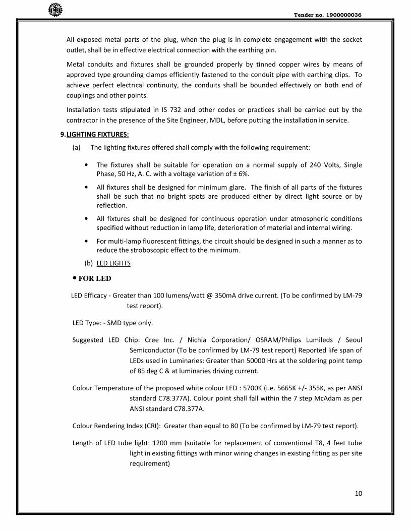
30
Sr. No. Length Use in
1 1m from switch to patch panel
2 3m from computer to information outlet
1. All patch cords shall exceed TIA/EIA and ISO/IEC Category 6/Classes E Specifications.
2. All patch cords shall be backward compatible with Category 5 and Category 5E systems
3. The patch cords shall incorporate an anti-snag feature that provides maximum
protection from snagging during moves and re-arrangements.
4. Patch cords shall be UL listed, UL-C certified and AUSTEL approved Patch cords shall support
network line speeds in excess of 1 gigabit per second
PHYSICAL SPECIFICATIONS:
Contact Material
: Phosphor Bronze
Contact Plating : Gold 50 micro-inch (1-27 microns) Nickel
100 micro-inches (2.54 microns)
Insertion Life : 750 minimum
Plug Material : Polycarbonate UL-rated 94 V-O
Operating Temperature: 14°F to 140°F (-10 °C to 60°C)
METHOD OF CONSTRUCTION:
The patch cords shall be erected for making connection from switch to patch panel or from
computer to information outlet.
MODE OF MEASUREMENT:
Executed quantity shall be counted on number basis.

Tender no. 1900000036
31
26. NETWORKING ACCESSORIES (NAS) LAN ACCESSORIES
A) UTP CONNECTOR (RJ-45)
GENERAL:
All material shall conform to relevant standard as per TIA/EIA 568-B2-1
SCOPE:
To make MIDX (Cross) patch cord required for cascade connections of switches & Routers.
MATERIAL:
UTP connector:
Assembly of Gold over nickel contacts with 1.5A current carrying capacity, 30V with milli ohms
contact resistance, 8P8C connection easy to crimp with crimping tool in polycarbonate UL94V
housing.
METHOD OF CONSTRUCTION:
The UTP cable shall be spliced, untwisted not more than 12mm, inserted into the connector
with sequence as shown in the diagram as per EIA/TIA 568 B-2-1& crimped firmly with
crimping tool.
MODE OF MEASUREMENT: Executed quantity shall be counted on number basis.
B) INFORMATION OUTLET (ETHERNET) (lO)
GENERAL:
All material shall conform to relevant standard as per TIA/EIA 568-B-2-1
SCOPE:
For connecting computer to wired LAN or external wireless Ethernet interface in Wireless LAN
MATERIAL:
INFORMATION OUTLET FLUSH/ SURFACE TYPE:
Spring shuttered front access, high impact plastic body FR grade with high performance
unshielded RJ-45 keystone jack (conforming to

Tender no. 1900000036
32
EIA/TIA 568-B-2-1 Cat 6), 15 millions contact resistance, gold over nickel spring contact, 1.5A
current carrying capacity with
T568A/T568B wiring option, insulation displacement connector for cable crimping to accept
22-26AWG solid wire for connections up to Gigabit Ethernet.
• All category 6 outlets shall meet or exceed Category 6 transmission requirements for
connecting hardware, as specified in TIA/EIA 568-B-2-1 Commercial Building
Telecommunications Cabling Standard and ISO/IEC 11801:2002 Second Edition
• The Category 6 outlets shall be backward compatible with Category 5E, 5, 3 Cords
and cables.
• The Category 6 outlets shall be of a universal design supporting T568A&B wiring
• The Category 6 outlets shall be capable of being in a modular patching situation
or as a modular telecommunication outlet (TO) supporting current 10BASE-
T,Token Ring,100 Mbps TP-PMD, 155 Mbps ATM, 622 Mbps ATM using parallel
transmission schemes and evolving high speed, high-bandwidth applications,
including Ethernet, 1000BASE-T and 1.2 Gbps ATM.
• The Category 6 outlets shall be capable of being installed at either a 45° or a
90 ° angle in any M- series modular faceplate, frame, or surface-mounted box
avoiding the need for special faceplates
• The Category 6 outlets shall have improved pair splitters and wider channel for
enhanced conductor placement. The outlet shall also have a low-profile wire
cap, which protects against contamination and secures the connection.
Multicolored identification labels shall be available to assure accurate installation.
HARDWARE:
Sheet Metal (SM) screws of required sizes, plugs, wooden gutties etc.
METHOD OF CONSTRUCTION:
The information outlet shall be fixed on the wall with sheet metal (SM) screws, rawl
Plugs/wooden gutties and making due connections as per EIA/TIA 568 B-2-2 by splicing
Tender no. 1900000036
33
the UTP cable, untwisted up to 12mm & punching the 4 pairs in the keystone jack with
the help of punching tool. Not a single wire shall be left without connections.
MODE OF MEASUREMENT: Executed quantity shall be counted on
Number basis.
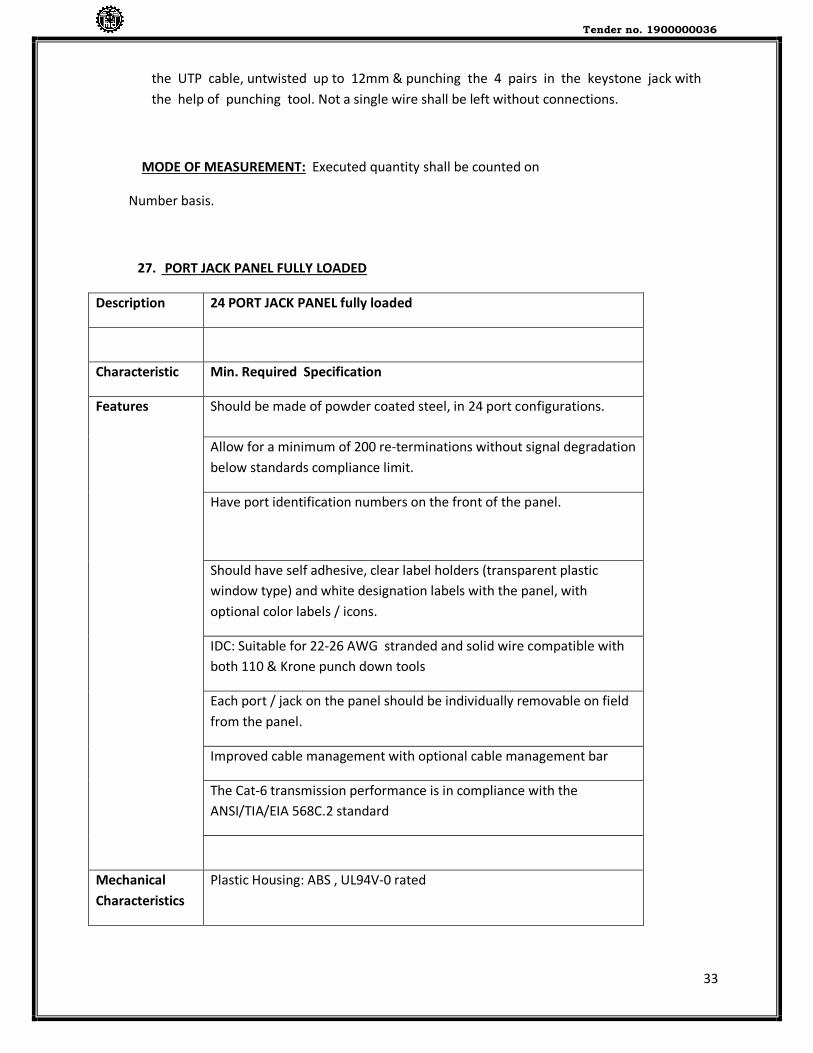
27. PORT JACK PANEL FULLY LOADED
Description 24 PORT JACK PANEL fully loaded
Characteristic Min. Required Specification
Features Should be made of powder coated steel, in 24 port configurations.
Allow for a minimum of 200 re-terminations without signal degradation
below standards compliance limit.
Have port identification numbers on the front of the panel.
Should have self adhesive, clear label holders (transparent plastic
window type) and white designation labels with the panel, with
optional color labels / icons.
IDC: Suitable for 22-26 AWG stranded and solid wire compatible with
both 110 & Krone punch down tools
Each port / jack on the panel should be individually removable on field
from the panel.
Improved cable management with optional cable management bar
The Cat-6 transmission performance is in compliance with the
ANSI/TIA/EIA 568C.2 standard
Mechanical
Characteristics
Plastic Housing: ABS , UL94V-0 rated

Tender no. 1900000036
34
Jack Connector Operating Life: Minimum 750 insertion cycles
Contact Material: Copper Alloy
Contact Plating: 50µ” Gold plated on plug contact area
Contact Force: 20N max ( IEC 60603-7-4)
Plug Retention Force: 15 lb.
IDC Connector Plastic Housing: Polycarbonate, UL94V-0 rated or equivalent
IDC cap : ABS, UL 94V -0
Contact Material: Copper Alloy
IDC Contact Plating: Phosphor bronze with tin plated
Insertion Force: 20N max ( IEC 60603-7-4 )
Wire Accommodation: 22-26 AWG solid
28. VGA CABLE
A Video Graphics Array (VGA) connector is a three-row 15-pin DE-15 connector. The 15-pin VGA
connector is found on many video cards, computer monitors, and some high definition
Television sets.
VGA connectors and cables carry analog component RGBHV (red, green, blue, horizontal sync, vertical
sync) video signals, and VESA Display Data Channel (VESA DDC) data. In the original version of DE-15
pinout, one pin was keyed and 4 pins carried Monitor ID bits which were rarely used; VESA DDC
redefined some of these pins and replaced the key pin with +5 V DC power supply.The VGA interface is
not engineered to be hotpluggable (so that the user can connect or disconnect the output device while
the host is running), although in practice this can be done and usually does not cause damage to the
hardware or other problems.
The required VGA Cable should be of 10Mtrs in Length respectively with end connectors complete
suitable to connect Laptop or P.C. to either projector or HDTV.
29. HDMI (High-Definition Multimedia Interface) CABLES
HDMI is a proprietary audio/video interface for transmitting uncompressed video data and
comppressed or uncompressed digital audio data from an HDMI compliant source device,

Tender no. 1900000036
35
such as a display controller, to a compatible computer monitor, video projector, digital
television, or digital audio device. HDMI is a digital replacement for analog video standards.
HDMI implements the EIA/CEA-861 standards, which define video formats and waveforms,
transport of compressed, uncompressed, and LPCM audio, auxiliary data, and
implementations of the VESA EDID. CEA-861 signals carried by HDMI are electrically
compatible with the CEA-861 signals used by the digital visual interface (DVI). No signal
conversion is necessary, nor is there a loss of video quality when a DVI-to-HDMI adapter is
used.)
The required HDMI Cable should be 10 Mtrs. and 20 Mtrs. in length complete with end
connectors suitable to connect with Projectors, HDTV & Laptops.
30. EPSON EB-X31 PROJECTOR
Supply, Installation, Testing and Commissioning of Epson make EB –X31 Projector with ceiling
mounting accessories complete with all documents, software and standard warranty.
31. 24 U WALL MOUNTING RACK
Supply, Installation, Testing and commissioning of 24 U Wall mounting Network Rack. The brief
technical specifications of Network Rack should be as given bellow.
- Width 800 mm x Depth 1000 mm,
- Perforated front and back door, side
Doors, locking facility,
- Rack with caster wheels and leveling feet,
- Digital temperature indicator,
- 4 no’s of fans,
- 4 no’s of shelf,
- 2 Vertical cable channels,
- Earth connectivity kit,
- 4 cable managers,
- 4 cable channels,
- 10 no’s of power sockets,
- Suitable for mounting routers/ switches/ firewalls
etc along with necessary screws and fittings.

Tender no. 1900000036
36
SCOPE OF WORK &
INSTRUCTION FOR MECHNICAL WORK

Tender no. 1900000036
37
AC INSTALLATION WORKS AT PROPOSED INTERIOR WORK OF CONFERENCE ROOM, FOR DND, NEW DELHI
SCOPE OF WORK
A) Works under this shall comprise of Supply, installation, testing and commissioning of following at
DND Conference room, New Delhi.
i) Inverter Cassette type Air conditioning units for Conference room consisting of indoor units,
outdoor units, cordless remote controllers, remote control holder, adequate length of power
supply cables along with connecting pin & accessories.
ii) Suitable L-shaped brackets duly painted with bush and fasteners for mounting outdoor units.
iii) Copper refrigerant piping with insulation/nitrile rubber sleeves including clamping/supporting
arrangement including making precise holes in the walls with core cutting m/c, and proper
finishing for connectivity from indoor to outdoor units.
iv) M.S stands, grill work, structural work as per site requirements for installation of A.C outdoor
units if necessitated as directed by MDL engineer.
v) ISI mark UPVC plumbing grade condensate drain pipe & fittings with supports & clamps etc. all
complete for taking out condensate drain water from AC units up to the nearest drain point as
directed by MDL engineer, including looping & 6 mm thk nitrile rubber insulation on drain pipe.
vi) 2.5 Sq mm 3 core Electrical cable for Inverter split AC (from indoor units to outdoor units) all
complete.
vii) Purging with suitable gas for flushing before leak test, leak testing of copper piping & first
charge of pre-filled refrigerant gas (eco-friendly refrigerant gas) considering lengths of copper
piping & A.C units capacity etc all complete.
viii) Supply, Installation, Testing and Commissioning of ceiling suspended fresh air inline fan single
phase 230 V of suitable dia. for fresh air.
ix) The contractor shall arrange free of cost servicing to be carried out by Air conditioner
Manufacturers service engineer for the completed works including indoor unit, outdoor unit,
copper tubing etc. all complete at the interval of every four months during Defect Liability
Period.
B) DRAWINGS AND DOCUMENTATION
i) The locations of the AC indoor units and outdoor units as shown in the tender drawings are
indicative and approximate.
It is intended to connect the condensate drain pipe of the cassette type indoor units with an
existing old drain line of 25 mm diameter. However, due to the technical reason or site
constraints if the connection of AC condensate drain is not possible with the existing drain
line, then the same is required to be installed, taking into consideration the site conditions,
constraints and after discussion and concurrence of MDL engineer.
Tender no. 1900000036
38
ii) After award of contract, Contractor is required to submit the print of installation/working
drawings of A3 size in 04 sets for the above scope of work and get it approved from MDL before
starting up the work. Drawings (plan and elevation) should indicate the exact locations of AC
indoor units, outdoor units, capacities of the ACs, copper tubing layout from indoor to outdoor
units and its size, condensate drain UPVC piping layout along with size and its looping/routing
from A.C indoor units to the nearest drain point. Drawing shall contain tabulation of all
measurable items of Equipment/Materials/works.
iii) Installation/Woking drawings shall be submitted for approval sufficiently in advance of installation
of any material to allow MDL Engineer ample time for scrutiny. No claims for extension of time
shall be entertained because of any delay in the work due to his failure to produce
installation/working drawings at the right time, in accordance with the approved program.
iv) When MDL Engineer makes any amendment in the above drawings, the contractor shall supply 02
fresh sets of drawings with the amendments duly incorporated, for approval. The contractor shall
submit further 02 sets of installation/working drawings to the Engineer for the exclusive use by
the MDL Engineer.
v) 4 sets of prints of approved drawings in A3 size to be submitted by the Contractor to MDL.
vi) Where drawings are approved, said approval does not mean that the drawings supersede the
contract requirements, nor does it in any way relieve the Contractor of the responsibility or
requirement to furnish material and perform work as required by the Contract.
vii) After completion of work, Contractor shall submit 04 sets of A3 size prints of “as built” drawings
and 02 sets on CD-R disc in a PC compatible AutoCAD & PDF format
C) MATERIALS, DESIGNS, INSTALLATIONS, TESTING & COMMISSIONING
i) Inverter split A.C units shall be factory assembled, wired and tested. It shall comprise of Indoor
and Outdoor Units along with all the accessories. Copper Refrigerant Piping interconnecting
evaporator and Condensing Unit shall be charged with eco friendly refrigerant gas and be
provided with suitable length of Copper Refrigerant Piping with insulation and cabling to be
provided per Evaporator Unit.
Condensing Unit shall be suitable for outdoor installation with weather proof enclosure and
shall be field serviceable. Also, the indoor unit & corresponding outdoor units shall be
numbered for identification as per installation drawing.
ii) Contractor to select the model from the preferred list of manufacturers of the Inverter split A.C
considering the climatic conditions prevailing through the year at New Delhi site. After award

Tender no. 1900000036
39
of Contract and before procurement, Contractor to submit, the make and models of the
Inverter split A.C units for all the tonnage capacities which the Contractor intends to supply,
install and commission at MDL site from the preferred list of manufacturers for approval.
Manufacturer’s technical catalogue and details of the make and models of the Inverter split
A.Cs to be furnished by the Contractor. Contractor to indicate the attainable cooling
temperature range for the selected A.C model.
iii) Copper refrigerant piping of suitable diameter compatible with the refrigerant gas & air
conditioner model with insulation/nitrile rubber sleeves (19 mm thk), end connections to be
installed true to line and level, jointing by brazing & adequately supported intermittently at
uniform distance with appropriate clamps / support arrangement including making precise holes
in walls with core cutting m/c & proper finishing for connectivity from indoor to outdoor unit etc
all complete as directed by MDL engineer. The alignment of copper piping in horizontal and
vertical direction to be maintained.
iv) Reputed make of ISI mark Hard UPVC plumbing grade condensate drain pipe & fittings to be
used for taking out condensate drain water from AC Units up to the nearest drain point as
directed by MDL engineer. Drain piping of specified sizes and suitable of 6 Kg/Sq cm. pressure
rating with water tight connections, leading from the room unit to a suitable drain point.
Complete drain piping shall be made leak proof and water tight by means of precise installation
and the use of leak proof sealant/adhesives. The joints shall be properly sealed so that there is
no water leakage. Proper grouping of condensate drain pipes & gradient to be maintained for
the easy flow of condensate drain water from the A.C units to the drain point. UPVC pipelines to
be adequately supported intermittently at uniform distance with clamps, pipe supports with
proper alignment in horizontal and vertical direction.
v) Inline fresh air fan -
The INLINE fresh air fan shall be designed for space saving / low noise generation. Inline fan
shall preferably be single skin with swing out motor; this fan shall be complete with casing
and impeller. Direction of discharge and rotation position shall be as per the job requirement
and shall be marked on the fan assembly.
Brief specifications for the fan are as under.
a. The proposed fan shall be complete with casing, motor and impeller. Direction of
discharge and rotation position shall be in line with the layout shown.
b. Housing shall be of GSS powder coated design. The duct/fresh air piping connections
at the inlet and discharge side of the fan shall be in accordance with the manufacturer
standards to avoid transmission of vibrations if any to the ducting / fresh air piping.
Suitable arrangement for connecting the fan to the fresh air pipe to be provided.
c. Impeller Fan shall have Aluminium impeller with backward curved blades suitable for
lowest sound power level. Impeller shall be statically and dynamically balanced.
Necessary acoustic insulation required to bring down the noise to the value specified in
the BOQ shall be carried out if required; the product shall be supplied with factory

Tender no. 1900000036
40
insulated design in this case.
d. Ball Bearings shall be completely maintenance free and can be used in any mounting
position at maximum indicated temperature.
e. Fan motor shall be energy efficient type have external rotor motor or IEC standard
motor supplied with built-in thermal contacts. At the critical high temperature point the
thermal contact shall open and break the power supply of the fan.
f. Drive of the fan shall be direct driven.
g. Performance Data - Fan shall be selected for the lowest operating noise power levels.
Capacity ratings, power consumption with operating points indicated shall be submitted
and verified at the time of testing and commissioning of the installation. All technical
data of fan should be as per AMCA accredited. High temp fan should have valid
European certification in accordance with EN12101-3.
h. The Fan should be supplied with Manufacturers Test Certificate.
vi) Unless otherwise specified and approved, all materials and designs shall comply with the current
issue of the relevant Indian or International Standard Specifications and their installation shall
comply with the relevant current Indian/International Standard Codes of Practices.
vii) Materials, designs and installations shall comply with the building regulations, local authority
regulations and by-laws, Gas Safety Regulations, National Electric Codes for the Electrical
Equipment of buildings, insurance company requirements and other statutory rules. All
equipment and materials shall be products, which shall meet with the acceptance of authorities
having jurisdiction over the work.
viii) Each item of Equipment/Material shall be a standard catalogue product of an established
manufacturer strictly from the manufacturers listed in the list of preferred makes.
ix) All equipment and materials required for installations shall be new and without blemish.
x) Preferred make for wall mounted Inverter Split Air conditioner Daikin/ Mitsubishi/Toshiba
xi) The contractor shall raise inspection call to MDL in the agreed format for the works undertaken at
below mentioned stages –
a) After delivery of material at site before starting of installation works
b) After installation for witnessing testing & commissioning of the completed works.
xii) All the works under or in course of execution or executed in pursuance of the contract shall at all
times be open to inspection & supervision of the MDL engineer / executives & the contractor at all
Tender no. 1900000036
41
times during the usual working hours offer assistance for the inspection of work.
xiii) The contractor shall submit supporting documents such as delivery challan(s), Test reports /
certificates, packing lists, Invoice, Performance guarantee certificates & other technical
documentation in requisite sets as relevant along with the invoice for the purpose of certification
by MDL engineer.
D) PROTECTION OF MATERIALS AND WORK
i) Copper tubes stored on site shall be supported clear of the ground and kept separate from all
other stored ferrous materials & shall be suitably protected against the weather.
ii) All equipments and materials, fixed or unfixed shall be protected against ingress of dirt or
moisture into working parts by means of Polythene covers or other equivalent measures.
iii) Precautions against mechanical damage by other trades shall be provided.
iv) Precautions shall be taken and all necessary protection provided to safeguard the work during bad
weather.
v) The inlet and discharges of all fan coils, and other terminal units shall be kept covered until all local
Plastering, Purging, etc. is completed and the units are ready to run.
vi) Equipment and material damaged shall be replaced by contractor at the discretion of the MDL
engineer. Equipment and materials are subject to rejection and replacement, if in the opinion of
the MDL Engineer, or in the opinion of the manufacturer's engineering department, the
equipment has deteriorated or been damaged to the extent that its immediate use is
questionable, or that its normal life expectancy has been curtailed.
vii) The contractor shall be solely responsible to protect all the delivered materials from the time of
delivery at site till satisfactory completion & handing over of the completed works from any
mode/type of damage/loss that may occur during this period.
E) INSTALLATION LIAISON
i) The Contractor is responsible for the co-ordination of all installation work on site. The Contractor
shall plan his installation before the work is commenced and to ensure correct installation to the
design intent during the course of construction. Any work, which has to be re-done due to
negligence in this respect, will not constitute an extra & also shall not amount to Extension of Time
to the Contract.
Tender no. 1900000036
42
ii) Contractor has to depute experienced and knowledgeable engineer/supervisors in the field of
HVAC who can co-ordinate, execute the work and take site decisions without any delay.
iii) The locations of the AC indoor units and outdoor units are shown in approximate positions on
the Tender Drawings, their exact location shall be determined from the approved installation
drawings.
iv) Particular care shall be taken to obtain uniform and tidy arrangements of wall mounted indoor
and outdoor units.
v) Where the work of the Contractor has to be installed in co-ordination with work of other trades,
he shall assist in working out space conditions to make a satisfactory adjustment.
F) OPERATION & MAINTENANCE MANUAL
Upon practical completion of the works, 03 copies of operation & maintenance manual shall be
provided. This manual shall be of loose leaf type A4 size with ready means of reference and a
detailed index.
The manual shall contain full operating and maintenance instructions presented in a form to deal
systematically with AC units. The manual may contain manufacturer's standard operating and
maintenance instructions and leaflets where these are applicable.
The contractor shall furnish Guarantee / warrantee certificate of each air conditioner unit duly
signed & stamped by the manufacturer, effective from the date of satisfactory completion &
acceptance of the completed works by MDL.
G) REFERENCE STANDARDS
Reference standards to be followed shall be of latest versions.
• ASHRAE Standards
• ASHRAE/ISHRAE Hand Books
• Safety Code for Mechanical Refrigeration, ASHRAE
• HVAC Commission Guideline (ASHRAE)
• IS 1239 for Piping AC INSTALLATION WORKS AT PROPOSED INTERIOR WORK OF CONFERENCE ROOM, FOR DND, NEW DELHI
BILL OF QUANTITIES

Tender no. 1900000036
43
PREAMBLE TO THE BILL OF QUANTITIES
1. GENERAL INSTRUCTIONS
1.1 The Bill of Quantities must be read with the scope of work, Conditions of Contract, Drawings and the Specifications and the Contractor shall be deemed to have examined the Scope of Work, Drawings, Specifications, Conditions of Contract and to have visited the Site and acquainted himself with the Works to be done and the way in which they are to be carried out and all factors affecting the execution of the Works and the Costs thereof including temporary works if required to complete the works.
1.2 All work shall be measured net as it is finished and/or fixed in the Works and no allowance
shall be made for wastage notwithstanding any general or local custom. Any items of work not covered in the Preamble shall be measured as per specifications for works methods laid down in relevant Indian Standards or as decided by the MDL Engineer.
1.3 The quantities set down against the items in this Bill of Quantities are an approximate
estimate of the quantity of each kind of work included in the Contract and are given for the convenience of forming a common basis for tendering. They are not to be taken as a guarantee that the quantities scheduled will be carried out or required or that they will not be exceeded. The MDL reserves the right to delete any item indicated in the bill of quantities at any time.
1.4 The quantities shall therefore not be considered as representing the final measurements, it
being the intention of the Contract (except where otherwise specifically stated) that the actual quantities of work ordered and carried out shall be jointly measured on completion by the MDL Engineer or his authorised representative and the Contractor and valued and paid for at such prices and rates entered by the Contractor in the Bill of Quantities.
1.5 The rates and prices set down against the items are to be the full inclusive value of the
finished work shown on the Drawing and/or described in the Specifications or which can reasonably be inferred there from and to cover the cost of every description of Temporary Works executed or used in connection therewith (except those items in respect of which specific provision has been separately made in this Bill of Quantities) and all the Contractor's obligations under the Contract including testing, giving samples and all matters and things necessary for the proper execution, completion and maintenance of the Works. No claim for additional payment shall be allowed for any error or misunderstanding by the Contractor of the work involved.
1.9 The Specifications and the various Sections in the Bill of Quantities are intended to
cover the supply of all the materials and the execution of all works necessary to complete the Works. Should there be any details of Materials or Construction which have not been referred to in the scope of work, specifications, Bill of Quantities or the Tender Drawings, but the necessity for which may reasonably be implied or inferred there from, or which are usual, or essential to the completion of all works in all trades, the same shall be deemed to be included in the rates and prices within in the Bill of Quantities. The rates and prices shall cover the items as described in the scope of work, Bill of Quantities, tender drawings and other terms and conditions of the contract.
1.10 The Contractor's unit rates and prices in the BOQ shall include
a) all equipment, apparatus, material, indicated in the BOQ, Scope of Work, Drawings, Specifications in connection with the item in question and also associated labour as well as all additional equipment, apparatus, material, consumables usually necessary to complete the system even though not specifically shown, described or otherwise referred to and also associated labour.
Tender no. 1900000036
44
b) It also includes delivering the material, item to the specified storage area at Site. Installation of the same in the specified location as per Drawing & as specified, testing and commissioning as per Specification and direction of the Engineer' at Site.
c) The unit price shall be deemed to include everything necessary to complete the work covered by this item in accordance with the scope of work, BOQ description, Specifications and Drawings.
d) The sum total of all the individual item prices shall represent the total price of the installation ready to be handed over.
e) All equipment, machinery, apparatus and materials required as well as the cost of any tests which the Engineer may request in addition to the tests generally required to prove quality and performance of A.C units. Further, if any equipment, machinery, apparatus and materials found to not comply/fulfil satisfactory performance/duty during such testing, then cost of replacing such materials.
f) Use of any tools, equipment, machinery, lifting tackle, ladders consumables etc. required by the Contractor to carry out his work.
g) All the necessary measures to prevent the transmission of vibration. Storage and insurance of all plant and equipment, apparatus and materials.
2. DETAILS OF MEASUREMENT
2.1. UNITS OF MEASUREMENT
The units of measurement used in this Bill of Quantities are in metric units as follows:
a. Linear Linear metre, centimetre or millimetre abbreviated to 'RM', 'cm' or 'mm' respectively.
b. Numbers Numbers abbreviated to No’s or No.
2.2 INVERTER SPLIT AIR CONDITIONER For measurement and certification of work for Supply & Delivery of Inverter Cassette Air
conditioner at MDL site, Contractor & MDL engineer will jointly verify the quantities by opening the boxes/package and verify the same with technical details furnished, damage due to transportation and handling etc before starting the installation work. Contractor to make all the arrangement for opening and closing of boxes/packages and store the same in proper manner after inspection.
2.3 REFRIGERANT PIPING
Copper piping shall be measured in running meters as actually installed along the centre line of the pipe line including pipe fittings. Copper piping work for refrigerant would be measured in running meters in one direction form indoor unit up to outdoor unit considering suction & discharge tubing as one combined set. Suction & discharge piping will not be measured separately one from another for certification of work done.
2.4 UPVC PIPING FOR CONDENSATE DRAIN
UPVC piping shall be measured in running meters as actually installed along the centre line of the pipe line including pipe fittings.