SCOPE OF WORK GALLIA #1 PROJECT Mink, Pettigrew...
81
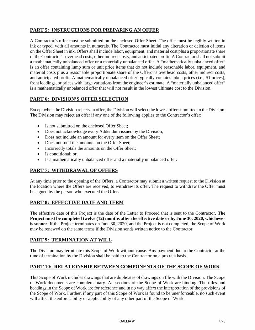
SCOPE OF WORK GALLIA #1 PROJECT Mink, Pettigrew, & Starcher Orphan Well Sites Gallia County, Addison Township PROJECT DESCRIPTION The Gallia #1 Project shall include the following wells: Well Name API Number County Township GPS: Latitude GPS: Longitude O. Mink #2 34-053-2-0006-00-00 Gallia Addison 38.900921° -82.207074° O. Mink #1 34-053-2-0005-00-00 Gallia Addison 38.902252° -82.202937° B&O Mink #1 34-053-2-0015-00-00 Gallia Addison 38.899510° -82.196369° Pettigrew #1 34-053-2-0075-00-00 Gallia Addison 38.899105° -82.194208° JH Starcher #1 34-053-6-0052-00-00 Gallia Addison 38.924314° -82.134924° JH Starcher #3 34-053-6-0110-00-00 Gallia Addison 38.923158° -82.137056° SCOPE OF WORK: This project includes the mobilization and development of the access to the well sites, cleaning out and plugging the orphan wells with cement, as well as regrading and revegetating all disturbed areas. DIRECTIONS: O. Mink #1 & #2 and B&O Mink #1: Take OH-7 into the Village of Addison and turn onto Addison Pike (CR-1). Take Addison Pike for 4.5 miles and turn right onto Bulaville Pike/Addison Pike. Follow Bulaville Pike (CR-3) west for 0.5 miles and the entrance to the B&O Mink #1 is on the left. All Mink wells will be accessed through the farm fields on the left-hand side of Bulaville Pike: O. Mink #2 access GPS 38.902570°, -82.207446°; O. Mink #1 access GPS 38.902979°, -82.202837°; and, B&O Mink #1 access GPS 38.900640°, -82.197231°. Pettigrew #1: Take OH-7 into the Village of Addison and turn onto Addison Pike (CR-1). Take Addison Pike for 4.5 miles and turn right onto Bulaville Pike/Addison Pike. Follow Bulaville Pike/Addison Pike west for 0.2 miles and turn left onto Bulaville Pike (CR-3). Follow Bulaville Pike south for 750 feet and the entrance to the well location is on the right, access GPS 38.897062°, -82.192147°. The well is located in Campaign Creek. JH Starcher #1 & #3: Take OH-7 into the Village of Cheshire and turn onto OH-554. Take OH-554 west for 0.6 miles and turn left onto Gravel Hill Road (CR-13). Take Gravel Hill Road south for 1.8 miles and the entrance to the JH Starcher #1 is on the left, access GPS 38.923419°, -82.136592°, and the entrance to the JH Starcher #3 is directly across the road on the right, access GPS 38.923406°, -82.136657°. GALLIA #1 1/75
Transcript of SCOPE OF WORK GALLIA #1 PROJECT Mink, Pettigrew...
SCOPE OF WORK GALLIA #1 PROJECT
Mink, Pettigrew, & Starcher Orphan Well Sites Gallia County, Addison Township
PROJECT DESCRIPTION The Gallia #1 Project shall include the following wells:
Well Name API Number County Township GPS: Latitude GPS: Longitude O. Mink #2 34-053-2-0006-00-00 Gallia Addison 38.900921° -82.207074° O. Mink #1 34-053-2-0005-00-00 Gallia Addison 38.902252° -82.202937° B&O Mink #1 34-053-2-0015-00-00 Gallia Addison 38.899510° -82.196369° Pettigrew #1 34-053-2-0075-00-00 Gallia Addison 38.899105° -82.194208° JH Starcher #1 34-053-6-0052-00-00 Gallia Addison 38.924314° -82.134924° JH Starcher #3 34-053-6-0110-00-00 Gallia Addison 38.923158° -82.137056°
SCOPE OF WORK: This project includes the mobilization and development of the access to the well sites, cleaning out and plugging the orphan wells with cement, as well as regrading and revegetating all disturbed areas. DIRECTIONS: O. Mink #1 & #2 and B&O Mink #1: Take OH-7 into the Village of Addison and turn onto Addison Pike (CR-1). Take Addison Pike for 4.5 miles and turn right onto Bulaville Pike/Addison Pike. Follow Bulaville Pike (CR-3) west for 0.5 miles and the entrance to the B&O Mink #1 is on the left. All Mink wells will be accessed through the farm fields on the left-hand side of Bulaville Pike: O. Mink #2 access GPS 38.902570°, -82.207446°; O. Mink #1 access GPS 38.902979°, -82.202837°; and, B&O Mink #1 access GPS 38.900640°, -82.197231°. Pettigrew #1: Take OH-7 into the Village of Addison and turn onto Addison Pike (CR-1). Take Addison Pike for 4.5 miles and turn right onto Bulaville Pike/Addison Pike. Follow Bulaville Pike/Addison Pike west for 0.2 miles and turn left onto Bulaville Pike (CR-3). Follow Bulaville Pike south for 750 feet and the entrance to the well location is on the right, access GPS 38.897062°, -82.192147°. The well is located in Campaign Creek. JH Starcher #1 & #3: Take OH-7 into the Village of Cheshire and turn onto OH-554. Take OH-554 west for 0.6 miles and turn left onto Gravel Hill Road (CR-13). Take Gravel Hill Road south for 1.8 miles and the entrance to the JH Starcher #1 is on the left, access GPS 38.923419°, -82.136592°, and the entrance to the JH Starcher #3 is directly across the road on the right, access GPS 38.923406°, -82.136657°.
GALLIA #1
1/75

SCOPE OF WORK GALLIA #1 PROJECT
Mink, Pettigrew, & Starcher Orphan Well Sites Gallia County, Addison Township
GENERAL SCOPE OF WORK The Contractor, the Contractor’s agents, representatives, and subcontractors shall perform this Plugging Project in accordance with Ohio Revised Code 1509, Ohio Administrative Code Chapter 1501:9-11 and 1501:9-12, the Agreement, and in accordance with the following documents that are attached hereto and made a part hereof:
1. Project Description; 2. General Scope of Work; 3. General Conditions; 4. General Specifications; 5. Sequence of Work; 6. Well Descriptions; 7. Plugging Plans; 8. Detailed Specifications; 9. Appendix I – Ohio One-Call; 10. Appendix II – Well Records; 11. Offer Sheet; 12. & Drawing Plan Set.
Subject to the Contractor’s compliance with this Scope of Work, Contractor is solely responsible for and has control over all plugging and reclamation construction means, methods, manners, techniques, sequences, and procedures, for safety precautions and programs in connection with the Plugging Project, and for coordinating all portions of the Plugging Project.
GALLIA #1
2/75

SCOPE OF WORK GALLIA #1 PROJECT
Mink, Pettigrew, & Starcher Orphan Well Sites Gallia County, Addison Township
GENERAL CONDITIONS PART 1: OHIO DEPARTMENT OF TRANSPORTATION SPECIFICATIONS This Gallia #1 Project (Project) references the Ohio Department of Transportation (ODOT) Construction and Material Specifications (ODOT CMS). Any reference to these specifications is to ODOT’s most current version of the specifications. The ODOT CMS can be found at: http://www.dot.state.oh.us/Divisions/ConstructionMgt/OnlineDocs/Pages/2019-Online-Spec-Book.aspx PART 2: PRE-SITE MEETING The Contractor or Contractor's representative must attend the pre-site meeting. Failure to attend the pre-site meeting is grounds for the Division to reject the Contractor’s Offer. The Ohio Department of Natural Resources, Division of Oil & Gas Resources Management (Division) intends to begin the pre-site meeting on time. At the meeting, the Division will circulate and collect attendance sign-in forms to all Contractors present. Only those Contractors in attendance throughout the pre-site meeting, including the discussion of the Scope of Work, will be considered present for the pre-site meeting. PART 3: MODIFICATIONS TO THE SCOPE OF WORK PRIOR TO AWARD The Scope of Work may only be altered by written modification. The Division may issue an Addendum to the Scope of Work and will provide the Addendum by email to all Department of Administrative Services (DAS) pre-qualified Contractors. Each Contractor is responsible for submitting an offer that is responsive to all Addenda issued. Failure to receive or acknowledge any Addenda does not release the Contractor from all obligations contained in all Addenda. All Addenda shall become part of the Scope of Work. Receipt of Addenda must be noted on the Contractor’s Offer Sheet. Any interpretation or clarification of the Scope of Work made by any person other than the Division, or in any manner other than a written Addendum, is not binding and the Contractor cannot rely upon any such interpretation or clarification. The Contractor cannot, at any time after the award of the Scope of Work, be compensated for any issue with the Scope of Work, including alleging insufficient data; incomplete, ambiguous, conflicting, or erroneous language; or, incorrectly assumed conditions regarding the nature or character of the work. PART 4: PERMIT AND INSPECTION REQUIREMENTS The Division will obtain and pay for all building and U.S. Army Corps of Engineers permits unless otherwise specified in the Detailed Specifications. However, the Contractor shall determine and include in his or her Offer Sheet the costs required to obtain and pay for all other requirements by the applicable governmental agencies; including but not limited to, all certificates of inspection/operation, guarantees, licenses, etc., required to complete the work as described within this document.
GALLIA #1
3/75
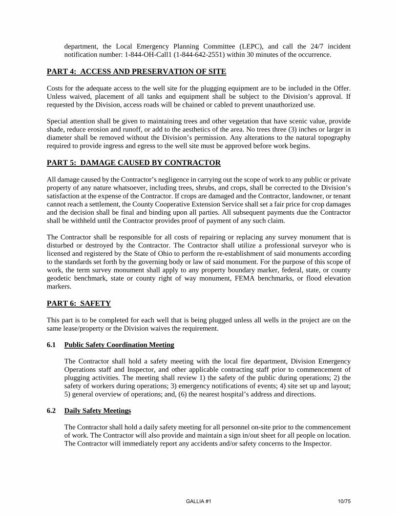
PART 5: INSTRUCTIONS FOR PREPARING AN OFFER A Contractor’s offer must be submitted on the enclosed Offer Sheet. The offer must be legibly written in ink or typed, with all amounts in numerals. The Contractor must initial any alteration or deletion of items on the Offer Sheet in ink. Offers shall include labor, equipment, and material cost plus a proportionate share of the Contractor’s overhead costs, other indirect costs, and anticipated profit. A Contractor shall not submit a mathematically unbalanced offer or a materially unbalanced offer. A “mathematically unbalanced offer” is an offer containing lump sum or unit price items that do not include reasonable labor, equipment, and material costs plus a reasonable proportionate share of the Offeror’s overhead costs, other indirect costs, and anticipated profit. A mathematically unbalanced offer typically contains token prices (i.e., $1 prices), front loadings, or prices with large variations from the engineer’s estimate. A “materially unbalanced offer” is a mathematically unbalanced offer that will not result in the lowest ultimate cost to the Division. PART 6: DIVISION’S OFFER SELECTION Except when the Division rejects an offer, the Division will select the lowest offer submitted to the Division. The Division may reject an offer if any one of the following applies to the Contractor’s offer:
• Is not submitted on the enclosed Offer Sheet; • Does not acknowledge every Addendum issued by the Division; • Does not include an amount for every item on the Offer Sheet; • Does not total the amounts on the Offer Sheet; • Incorrectly totals the amounts on the Offer Sheet; • Is conditional; or, • Is a mathematically unbalanced offer and a materially unbalanced offer.
PART 7: WITHDRAWAL OF OFFERS At any time prior to the opening of the Offers, a Contractor may submit a written request to the Division at the location where the Offers are received, to withdraw its offer. The request to withdraw the Offer must be signed by the person who executed the Offer. PART 8: EFFECTIVE DATE AND TERM The effective date of this Project is the date of the Letter to Proceed that is sent to the Contractor. The Project must be completed twelve (12) months after the effective date or by June 30, 2020, whichever is sooner. If the Project terminates on June 30, 2020, and the Project is not completed, the Scope of Work may be renewed on the same terms if the Division sends written notice to the Contractor. PART 9: TERMINATION AT WILL The Division may terminate this Scope of Work without cause. Any payment due to the Contractor at the time of termination by the Division shall be paid to the Contractor on a pro rata basis. PART 10: RELATIONSHIP BETWEEN COMPONENTS OF THE SCOPE OF WORK This Scope of Work includes drawings that are duplicates of drawings on file with the Division. The Scope of Work documents are complementary. All sections of the Scope of Work are binding. The titles and headings in the Scope of Work are for reference and in no way affect the interpretation of the provisions of the Scope of Work. Further, if any part of this Scope of Work is found to be unenforceable, no such event will affect the enforceability or applicability of any other part of the Scope of Work.
GALLIA #1
4/75

If a conflict between the drawings and the specifications arises, the Contractor must notify the Division. In the event of a conflict of any provision in the Scope of Work, the order of priority within the Scope of Work is as follows: Drawings; Detailed Specifications; General Specifications; Plugging Plan; then, Sequence of Work. PART 11: CONTRACTOR’S RESPONSIBILITY FOR SUBCONTRACTORS The Contractor is responsible for the conduct of its subcontractors and for persons its subcontractors directly or indirectly employ. PART 12: STANDARDS If the Division identifies a “standard” by reference to manufacturer and/or model number, all offers will be evaluated to ensure that the identified standard is used. The Division will not consider an offer in which a substitution for the standard is offered. After the Letter to Proceed is issued, the Contractor may submit a written proposal for a substitution of a standard. PART 13: SUBSTITUTIONS DURING THE PROJECT After the Letter to Proceed is issued, the Contractor may offer substitutions for the standards set forth in the Scope of Work. The decision to allow substitution is solely within the discretion of the Division, which will consider, among other factors, availability, time of delivery, the aesthetic value of the proposed substitution, general differences in the knowledge of the product, service history, quality, efficiency, performance, and architectural, engineering, inspection, testing and administrative expenses. Any changes to the Offer price and/or Scope of Work must be memorialized by a Field Order or Change Order, as applicable. The savings in cost in allowing any substitutions during the Project will be solely to the benefit of the Division. PART 14: QUANTITIES OF WORK 14.1 Unit Price Items
For items in the Offer that require a unit price, the quantities listed on the Offer Sheet are an approximation and are to be used only for the comparison of offers. The scheduled quantities may be increased or decreased without invalidating or altering the Offer and will be considered within the Scope of Work. Payments for unit price items will be made to the Contractor for actual quantities of work performed and materials furnished in accordance with the Scope of Work; however, the Contractor may not exceed the unit quantities shown on the Offer Sheet without prior written approval of the Division through a Field Order. Even if the Contractor determines that additional unit priced quantities (above and beyond the original Offer Sheet quantity) are required to meet plan and/or specification dimensions, the Contractor must not exceed the Offer Sheet quantities without prior approval of the Division. The Division will not pay for quantities above and beyond the Offer Sheet quantity without prior approval of the Division.
14.2 Lump Sum Items
For items in the Offer Sheet that require a lump sum price, the Division will not pay for work, materials, or equipment that exceeds the amount provided by the Contractor on the Offer Sheet. The
GALLIA #1
5/75

lump sum price on the Offer Sheet must include all work, materials, and equipment necessary to properly complete the Project.
14.3 Additional/Contingency Items
The contingency items set forth in the Offer Sheet are not projected as necessary to complete the Project. Rather, the contingency items will first be used when unforeseen work arises and the Division determines the contingency item is applicable. To be compensated for contingency items, the Contractor must have a written Field Order from the Division authorizing the contingency item in a specified quantity. Use of contingency items will not require the execution of a Change Order. The Contractor must be prepared to supply all items identified in the contingency specifications for use on this Project.
PART 15: OMISSIONS IN THE SCOPE OF WORK If the Contractor notices an error or omission in the Scope of Work during performance of the Project, the Contractor shall immediately notify the Division of such omission or error and shall not proceed with the Project until directed by the Division. Any work performed by the Contractor prior to clarification by the Division may not be entitled to compensation. PART 16: INTERPRETATIONS CONCERNING THE SCOPE OF WORK During the Project, if a question arises on the Scope of Work, the labor or materials to be supplied, or costs potentially exceeding the Contractor’s Offer, such questions must, prior to the work being performed, be submitted to the Division for a determination. A Division determination will be issued in writing and any work performed prior to such a determination will be performed at no cost to the Division. The Division will also begin executing a Change Order, when appropriate. If the Division receives a written question concerning the Project, the Division will determine if the work must be performed by the Contractor at no increase in price to the Scope of Work. If so, the Division will issue a Field Order setting forth the Division’s determination. Each Field Order issued must be signed by the Contractor acknowledging receipt. If the Contractor disagrees with the Division’s interpretation in a Field Order, the Contractor may submit a protest by certified mail to the Chief within ten (10) days following the date of issuance of the protested Field Order. However, the Contractor must immediately proceed with the instructions given in the issued Field Order. If, upon receipt of a written protest of a Field Order, the Division determines that the work referred to in the protest is outside the Scope of Work, the Division will not issue a Field Order and instead will issue a Change Order. Field Orders, which are interpretations of the requirements of the Scope of Work, may be issued by the Division at any time during the performance of the work. The Contractor, at all times, is required to immediately execute the instructions of all issued Field Orders. PART 17: CHANGES IN THE SCOPE OF WORK 17.1 The Division's Right to Require Change Orders
The Division may issue a Change Order directing the Contractor to immediately perform extra work that differs from the Scope of Work. The Contractor shall perform the work as directed. The changes in the work will consist of additions, deletions, or other revisions. When the Contractor performs the work, the Offer amount will be adjusted as described within this Scope of Work.
GALLIA #1
6/75

If the Contractor protests the issuance of the Change Order, any such protest has no bearing on any work requirements arising out of the Change Order in that the Contractor must immediately perform the work required in the Change Order so as not to delay the progress of the work at the Project.
17.2 Unauthorized Work
Only work performed under the Scope of Work, or work authorized by a Field Order or a Change Order, is eligible for compensation. If the Contractor performs any work or purchases any materials without an approved, applicable Field Order or Change Order, such work performed and purchases made are within the Scope of Work at no additional cost to the Division.
17.3 Contractor's May Request Change Orders
If the Contractor determines that the Scope of Work does not address conditions at the Project, the Contractor may provide written notice to the Division of the conditions and request a Change Order. No oral communications will be acceptable as justification for a Change Order.
17.4 Determining Price of a Proposed Change Order
The following methods will be used to determine the price of a proposed Change Order: a. If a Change Order involves items not listed on the Offer Sheet, the Contractor must present
the Division with labor and/or material price quotes for the proposed Change Order item(s). The Division may request these quotes either in unit prices or as lump sums. Or,
b. If the work involved in the Change Order is not definable, the Division may request the work
be performed on a time and material basis and include a maximum amount to be paid for the work. The method will be based on unit prices for both labor and materials agreed to by the Division prior to the Contractor commencing the work.
17.5 Disputes Regarding Change Order Prices
If the Contractor and the Division cannot agree on the cost of the work for a Change Order using site-specific information including, but not limited to, Division historic public offer information, the Division will determine and set a fair price for the work and materials that are the subject of the Change Order.
PART 18: PAY ESTIMATES 18.1 General Information
Payments issued to the Contractor as the work progresses are not acceptance of any portion of the work not completed in accordance with the Scope of Work nor do such payments relieve the Contactor of liability with respect to any obligation or any expressed or implied warranties or responsibilities for faulty materials or workmanship.
18.2 Required Review by the Division
Prior to the submittal of each payment request, the Contractor and the Division must meet at the Project site to review the Project progress. The Contractor and the Division's Project Representative must mutually agree on quantity and percent of work completed for all offer items prior to submittal
GALLIA #1
7/75

of each payment request. No payment request will be approved for work that has not been approved by the Division's Project Representative. Field verification of all lump sum quantities and weight slips for all unit price quantities invoiced must be submitted to the Division’s Project Representative for review during the meeting. Payment requests received by the Division containing errors or requesting amounts that cannot be approved will be returned to the Contractor. The Contractor may resubmit a payment request after correcting errors.
18.3 Documents to be Submitted for Payment
The Contractor's payment request must be submitted to the Division by regular mail to 2207 Reiser Avenue, SE, New Philadelphia, Ohio 44663, or alternatively via email to the Division at [email protected]. The Contractor's payment request must be submitted on a form furnished by the Division. Each request for payment must be signed by the Contractor and the Contractor must certify on the form that: a. The request for payment is accurate as to materials and the work completed under the terms
and conditions of the Scope of Work and any Change Order, as applicable, including full compliance with all labor provisions; and,
b. All subcontractors and material suppliers have been paid for the work or materials that are
applicable to all previous payment requests. As certification, each request for payment, at the Division’s request, may need to be accompanied with a properly executed "Waiver of Liens" from all subcontractors and material suppliers to show that all previous payments made by the Division to the Contractor have been applied to fulfill, in full, all of the Contractor's obligations reflected in prior requests for payment.
18.4 Effect of Liens on Payment Requests
All work, materials, and equipment covered by any request for payment, whether incorporated in the Project or not, will pass to the Division at the time of payment free and clear of all liens, claims, security interests, and encumbrances.
If there is evidence of any lien or claim that is chargeable to the Contractor, the Division will withhold all payments due to the Contractor to secure such lien or claim. If there are any previous liens or claims after payments are made to the Contractor, the Contractor may be required to refund to the Division a sum of money equal to the sum of all monies that the Division may be compelled to pay in discharging any lien or claim as a result of the Contractor's default. PART 19: RETAINAGE FOR FINAL STABILIZATION If the Scope of Work requires revegetation of a disturbed area, the Division will retain five percent (5%) of the sum of: (1) the Offer amount; and, (2) all approved Change Orders. The five percent (5%) amount retained shall be released once the Division completes a Final Stabilization Inspection and determines that vegetation has reached final stabilization. “Final stabilization” means vegetation established in a uniform perennial vegetative cover with at least a seventy percent (70%) grass cover. “Final stabilization” also means that no large barren areas exist and the vegetation is of an equal or better condition than before the project started. The Contractor must remove all temporary erosion and sediment controls once final stabilization is achieved.
GALLIA #1
8/75

SCOPE OF WORK GALLIA #1 PROJECT
Mink, Pettigrew, & Starcher Orphan Well Sites Gallia County, Addison Township
GENERAL SPECIFICATIONS Unless there is a specific pay item in the Detailed Specifications, the work defined in the General Specifications shall be incorporated into other items of work. PART 1: HOURS OF WORK The Contractor, the Contractor’s agents, representatives and subcontractors shall perform plugging projects during the days of Monday through Friday. Work will not be conducted on weekends or state/national holidays except with Division approval or during emergency situations. A work day is defined as eight (8) hours; however, additional hours may be worked with Division approval or during emergency situations. PART 2: EQUIPMENT The Contractor equipment shall pass all safety requirements of local, state, and federal agencies. The Ohio Department of Natural Resources, Division of Oil and Gas Resources Management reserves the right to inspect the equipment prior to the Recommendation of Award. Unless otherwise noted, all equipment and materials required to complete the work described shall be provided by the Contractor. PART 3: NOTIFICATIONS 3.1 Seven Working Day Notice
The Contractor, the Contractor’s agents, representatives, subcontractors, or independent contractors shall contact the responsible Division Orphan Well Inspector (the “Inspector”) no less than seven (7) working days prior to commencement of work. Notice may be written or oral. This notice will allow the appropriate Division staff time to mark the approved access route and any sensitive areas that need to be left undisturbed. The Contractor, the Contractor’s agents, representatives, and sub-contractors shall contact each utility company that has utilities that directly affect plugging activities at the well locations.
3.2 Public 48 Hour Notice
Prior to initiating well plugging operations, the Contractor shall give a minimum of 48-hour notice to the local fire department. Confirmation of this notification shall also be made to the Inspector or the Division Regional Office.
3.3 Emergency Notification
When emergency conditions are encountered, such as a release of hydrogen sulfide gas (H2S), natural gas, crude oil, condensate, or brine that threatens human health, safety, or the environment, as described in Ohio Administrative Code 1501:9-08-02, the Contractor shall notify the local fire
GALLIA #1
9/75
department, the Local Emergency Planning Committee (LEPC), and call the 24/7 incident notification number: 1-844-OH-Call1 (1-844-642-2551) within 30 minutes of the occurrence.
PART 4: ACCESS AND PRESERVATION OF SITE Costs for the adequate access to the well site for the plugging equipment are to be included in the Offer. Unless waived, placement of all tanks and equipment shall be subject to the Division’s approval. If requested by the Division, access roads will be chained or cabled to prevent unauthorized use. Special attention shall be given to maintaining trees and other vegetation that have scenic value, provide shade, reduce erosion and runoff, or add to the aesthetics of the area. No trees three (3) inches or larger in diameter shall be removed without the Division’s permission. Any alterations to the natural topography required to provide ingress and egress to the well site must be approved before work begins. PART 5: DAMAGE CAUSED BY CONTRACTOR All damage caused by the Contractor’s negligence in carrying out the scope of work to any public or private property of any nature whatsoever, including trees, shrubs, and crops, shall be corrected to the Division’s satisfaction at the expense of the Contractor. If crops are damaged and the Contractor, landowner, or tenant cannot reach a settlement, the County Cooperative Extension Service shall set a fair price for crop damages and the decision shall be final and binding upon all parties. All subsequent payments due the Contractor shall be withheld until the Contractor provides proof of payment of any such claim. The Contractor shall be responsible for all costs of repairing or replacing any survey monument that is disturbed or destroyed by the Contractor. The Contractor shall utilize a professional surveyor who is licensed and registered by the State of Ohio to perform the re-establishment of said monuments according to the standards set forth by the governing body or law of said monument. For the purpose of this scope of work, the term survey monument shall apply to any property boundary marker, federal, state, or county geodetic benchmark, state or county right of way monument, FEMA benchmarks, or flood elevation markers. PART 6: SAFETY This part is to be completed for each well that is being plugged unless all wells in the project are on the same lease/property or the Division waives the requirement. 6.1 Public Safety Coordination Meeting
The Contractor shall hold a safety meeting with the local fire department, Division Emergency Operations staff and Inspector, and other applicable contracting staff prior to commencement of plugging activities. The meeting shall review 1) the safety of the public during operations; 2) the safety of workers during operations; 3) emergency notifications of events; 4) site set up and layout; 5) general overview of operations; and, (6) the nearest hospital’s address and directions.
6.2 Daily Safety Meetings
The Contractor shall hold a daily safety meeting for all personnel on-site prior to the commencement of work. The Contractor will also provide and maintain a sign in/out sheet for all people on location. The Contractor will immediately report any accidents and/or safety concerns to the Inspector.
GALLIA #1
10/75

6.3 Operational Standards
The Contractor shall follow the rules established by Occupational Safety and Health Administration (OSHA) Basic Construction Safety 29 CFR 1926 on all onsite project operations.
6.4 Excavation and Trenching Requirements
The Contractor shall follow the notification protocol as specified in Part 3 of the General Specifications before the start of any excavating activities. The Contractor will comply with OSHA Construction Standards for excavation and trenching under 29 CFR 1926 Subpart P.
6.5 Hazardous Communications Requirements
The Contractor shall maintain Safety Data Sheets (SDS) for all chemicals stored and/or used on-site. A copy of all SDS will be supplied to the local fire department and to the Division.
6.6 Site Security
The Contractor shall provide and install protective barriers/fencing around the work area to prevent unauthorized access. Ingress and egress access must be maintained at all times.
6.7 Wind Direction Indicator The Contractor shall install a windsock in an open area of the well location where it is visible to all onsite personnel. It shall be constructed of high visibility material and deployed no less than six (6) feet above grade during the plugging operations.
6.8 Muster and Smoking Areas
The Contractor shall mark and assign a primary and a secondary muster area daily upwind of the well location. These are to be determined based on prevailing wind direction, as indicated by the windsock. The Contractor will post an emergency contact information sheet at each muster site. The Contractor will establish a safe location for a designated smoking area.
6.9 Ignition Sources and Parking Areas The Contractor shall identify and mark all potential ignition sources within a 50-foot radius of the well. The designated parking area will be outside the 50-foot radius from the well.
6.10 Air Monitoring and Worker Safety The Contractor shall supply and place a 4-gas monitor at the wellhead. The gas monitor must be calibrated and maintained to monitor Methane (CH4), Oxygen (O2), Carbon Monoxide (CO), and Hydrogen Sulfide (H2S).
Stop work must be followed when any of the levels listed below occur: • Methane – 1,000 parts per million (ppm)/5% Lower Explosive Limit (LEL); • Oxygen – saturation below 19.5% or above 23%; • Carbon Monoxide – 50 ppm; or, • Hydrogen Sulfide – 10 ppm.
GALLIA #1
11/75

The levels stated above are directly from the Occupational Safety and Health Administration (OSHA) and The National Institute for Occupational Safety and Health (NIOSH) and are standard for air monitoring procedures for safety and work environments. If any of the above levels are alarmed, all personnel will shut down ignition sources and report to the muster area. From the muster area, the Contractor will call 911 for assistance from the local fire department. Division Emergency Operations personnel or the Inspector has the right to stop work if the actions are unsafe or the actions cause or are likely to cause danger to the workers, public, or the environment.
PART 7: MAINTENANCE OF TRAFFIC The Contractor shall, at all times, install, maintain, and operate all traffic and traffic control devices in conformance with the requirements of the "Ohio Manual of Uniform Traffic Control Devices for Streets and Highways," hereinafter called, “The Ohio Manual.” The Contractor shall notify the appropriate public officials and the Division and shall obtain all required approvals prior to any lane closure of a public road. The Contractor shall maintain ingress/egress to all properties associated with the project at all times during the project unless agreed upon in writing by the Division and the landowner. PART 8: PROTECTION OF EXISTING UTILITIES Before construction begins, the Contractor, acting as an agent for the Division, shall locate all utilities in the vicinity of the work. The Contractor shall be responsible for complying with the regulations pertaining to utilities in the State of Ohio. The Contractor shall assume all risk for all utilities located in the vicinity of the work, whether above or below the surface of the ground. The Contractor shall also be responsible for all damages and assume all expense for direct or indirect injury, caused by his work, to any of the utilities, or any person or property by reason of injury to them, whether such utilities are or are not shown on the drawings, once they have been uncovered by the work. In compliance with Ohio Revised Code 3781, two working days before digging the Contractor shall contact the Ohio Utility Protection Service (OUPS) and Oil and Gas Producers Underground Protection Service (OGPUPS) using the Ohio811 one call service by calling 811 or by using the i-dig login found on the internet at OHIO811.org. The Contractor shall maintain a current OUPS/OGPUPS call ticket during the entire project. PART 9: EROSION AND SEDIMENT CONTROL Temporary erosion control measures are required during the course of this project. These measures may consist of the installation of straw bale dikes, silt fence, filter socks, inlet protection structures, erosion control blankets, energy dissipation, and temporary seeding and mulching. Once construction begins, the Contractor shall be solely responsible for all construction related to the control of off-site sedimentation. This sediment shall be removed by the Contractor at the Division's direction. 9.1 Temporary Measures
Temporary erosion control structures shown on the Drawing Plan Set, identified with these specifications, or as directed by the Division, shall be placed as soon as construction starts and must be maintained during the course of the project. At the direction of the Division, the Contractor shall remove the temporary controls when they are no longer needed or when required permanent control measures have been completed.
GALLIA #1
12/75

If sediment escapes the site, accumulations must be removed at a frequency to minimize further negative effects, and whenever feasible, prior to the next rain event.
9.2 Maximum Exposed Areas
Stabilization measures must be initiated as soon as practicable in portions of the site where construction activities have temporarily or permanently ceased, and except as provided below, must be initiated no more than seven (7) days after the construction activity in that portion of the site has temporarily or permanently ceased. Where the initiation of stabilization measures by the seventh day after construction activity temporarily or permanently ceased is precluded by snow cover, or frozen ground conditions, stabilization measures must be initiated as soon as practicable. Where construction activity on a portion of the site is temporarily ceased, and earth-disturbing activities will be resumed within fourteen (14) days, temporary stabilization measures do not have to be initiated on that portion of the site. The Division shall limit the area of excavation, borrow, and embankment operations in progress commensurate with the Contractor’s capability and progress in keeping the finished grading, re-soiling, mulching, seeding, and other such permanent control measures current in accordance with the acceptable schedule.
9.3 Winterization
When an incomplete project will be left exposed throughout the winter season, the Contractor shall furnish the Division a plan indicating the control measures to be installed and maintained until the next construction season. If the winter period falls within the anticipated construction period of the Scope of Work and as indicated in the original approved construction schedule, control structures will be paid for by the Division at the unit prices in the Offer. If the project is not substantially completed prior to the winter season due to the failure of the Contractor to meet the completion date, these necessary control structures will be installed and maintained by the Contractor at his expense and these items will not be paid for under the terms of the Scope of Work, except those that are permanent facilities to be left in place in accordance with the Drawing Plan Set and Specifications.
9.4 Other Controls
Off-site vehicle tracking of sediments and the generation of dust must be minimized and any waste must be properly disposed.
9.5 Inspections
The Division Inspector shall conduct inspections to ensure that the control practices are functional and to evaluate whether the erosion and sediment control measures are adequate and properly implemented.
GALLIA #1
13/75
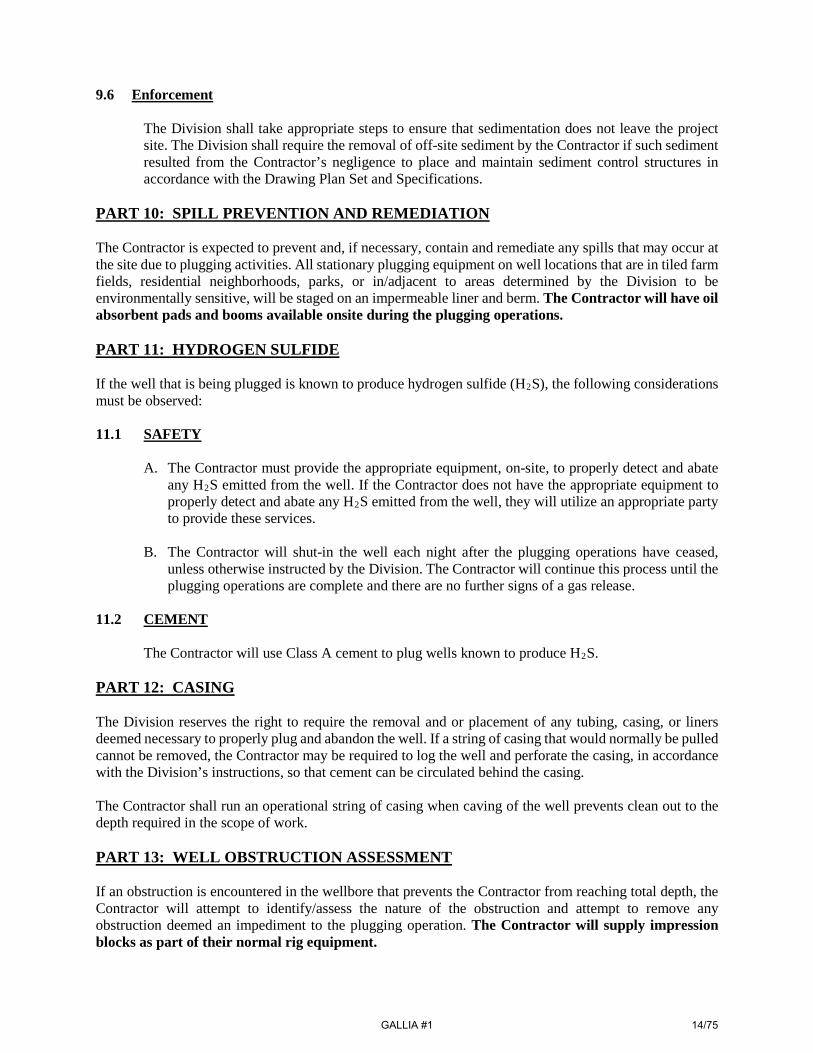
9.6 Enforcement
The Division shall take appropriate steps to ensure that sedimentation does not leave the project site. The Division shall require the removal of off-site sediment by the Contractor if such sediment resulted from the Contractor’s negligence to place and maintain sediment control structures in accordance with the Drawing Plan Set and Specifications.
PART 10: SPILL PREVENTION AND REMEDIATION The Contractor is expected to prevent and, if necessary, contain and remediate any spills that may occur at the site due to plugging activities. All stationary plugging equipment on well locations that are in tiled farm fields, residential neighborhoods, parks, or in/adjacent to areas determined by the Division to be environmentally sensitive, will be staged on an impermeable liner and berm. The Contractor will have oil absorbent pads and booms available onsite during the plugging operations. PART 11: HYDROGEN SULFIDE If the well that is being plugged is known to produce hydrogen sulfide (H2S), the following considerations must be observed: 11.1 SAFETY
A. The Contractor must provide the appropriate equipment, on-site, to properly detect and abate any H2S emitted from the well. If the Contractor does not have the appropriate equipment to properly detect and abate any H2S emitted from the well, they will utilize an appropriate party to provide these services.
B. The Contractor will shut-in the well each night after the plugging operations have ceased, unless otherwise instructed by the Division. The Contractor will continue this process until the plugging operations are complete and there are no further signs of a gas release.
11.2 CEMENT
The Contractor will use Class A cement to plug wells known to produce H2S.
PART 12: CASING The Division reserves the right to require the removal and or placement of any tubing, casing, or liners deemed necessary to properly plug and abandon the well. If a string of casing that would normally be pulled cannot be removed, the Contractor may be required to log the well and perforate the casing, in accordance with the Division’s instructions, so that cement can be circulated behind the casing. The Contractor shall run an operational string of casing when caving of the well prevents clean out to the depth required in the scope of work. PART 13: WELL OBSTRUCTION ASSESSMENT If an obstruction is encountered in the wellbore that prevents the Contractor from reaching total depth, the Contractor will attempt to identify/assess the nature of the obstruction and attempt to remove any obstruction deemed an impediment to the plugging operation. The Contractor will supply impression blocks as part of their normal rig equipment.
GALLIA #1
14/75
PART 14: REMOVAL OF AN OBSTRUCTION The removal of an unknown obstruction that is encountered during the cleanout of a well may include the use of milling and/or fishing tooling and equipment. The Contractor will include the costs for these services on the appropriate line items in the contingency section of this offer unless these costs are part of a planned procedure. The Division will approve a method for the Contractor to remove the well obstruction. The Division will first utilize contingency specifications and line items to define this work. The Division will not be responsible for milling or fishing charges that are due to Contractor negligence or Contractor equipment failure. PART 15: PLUGGED WELL IDENTIFICATION In compliance with Ohio Administrative Code 1501:9-11-10, a steel plate, a minimum of ¼-inch thick, shall be tack welded on top of all plugged wells. The well’s permit number and “ODNR” shall be welded on the plate in numbers/letters as large as practical. Letters shall have a minimum relief of 1/8-inch. PART 16: TOILET FACILITIES Where there are no readily accessible public toilet facilities, the Contractor will provide a portable field toilet on the location during plugging operations.
GALLIA #1
15/75

SCOPE OF WORK GALLIA #1 PROJECT
Mink, Pettigrew, & Starcher Orphan Well Sites Gallia County, Addison Township
SEQUENCE OF WORK
General: Performance of all work shall be coordinated with the Division of Oil and Gas Resources Management (“Division”) Orphan Well Inspector (“Inspector”). The Sequence of Work shall be repeatable for all the project’s wells. The Sequence of Work for the Orphan Well Project shall be as follows: Phase I:
1) Contact the Ohio Utility Protection Service and the Ohio Oil & Gas Producers Underground Protection Service.
2) Coordinate with the Orphan Well Inspector and the local authorities for the mobilization of equipment over the roads and bridges to the site as applicable.
3) Verify with the Orphan Well Inspector that the pre-construction staking (i.e., Construction Work
Limits) has been completed by the Division. The pre-construction staking must be completed prior to mobilization.
Phase II:
1) Mobilize all necessary equipment to the site and develop the site access as shown on the Drawing Plan Set.
2) Implement site safety and secondary containment as described in the Detailed Specifications.
3) Install perimeter sediment controls as required by the Division.
4) Prepare the well for plugging as described in the Detailed Specifications, “Wellhead Control”.
5) Upon successful installation and approval of the wellhead and establishment of well control, the
Contractor shall begin to plug the well as described in the Plugging Plan and Detailed Specifications, “Well Preparation & Plugging”.
6) Once all required plugs have been placed and allowed to set, the Contractor shall cut the casing as
defined in the Plugging Plan.
7) The Contractor shall set the plugged well identification as outlined in the General Specifications and Ohio Administrative Code 1501-9-11-10.
Phase III:
1) Within three (3) working days after the plugging operations are completed, the Contractor shall remove all well and well plugging-related equipment, fluids, and cuttings from the site. The Contractor shall also excavate and remove all contaminated soils onsite, if present.
2) Within fourteen (14) days after the completion of the plugging operations, the Contractor shall
GALLIA #1
16/75

resoil, as applicable, final grade, disc, fertilize, seed, and mulch all disturbed areas.
3) All reclamation shall be finished to an equal or better condition than what existed prior to construction. The Division shall give the final approval for the restoration of the site.
GALLIA #1
17/75
SCOPE OF WORK GALLIA #1 PROJECT
Mink, Pettigrew, & Starcher Orphan Well Sites Gallia County, Addison Township
WELL DESCRIPTION
This Well Description is for: O. Mink #2, API #34-053-2-0006-00-00, Gallia County, Addison Township. O. Mink #1, API #34-053-2-0005-00-00, Gallia County, Addison Township. B&O Mink #1, API #34-053-2-0015-00-00, Gallia County, Addison Township. Background: The Mink wells are located 3.5 miles west of the Village of Addison. The O. Mink #1 & #2 are situated on Parcel #00100187402 which is 107.61 acres and owned by John and Kimberly Vanmeter. The B&O Mink #1 is situated on Parcel #00100173300 which is 57.86 acres in size and owned by Donald and Marjorie Mink. Division inspections conducted in 2017 and 2018 noted the following: O. Mink #2: This well is equipped with 8.63-inch outside diameter (OD) casing and 2.38-inch OD tubing that is assumed to be set on a packer. The well is leaking natural gas from the casing-tubing annulus. Drilling records indicate that the well was drilled in 1938 to a depth of 1,538 feet in the 2nd Berea Sandstone; and, it is assumed the well was completed in the 2nd Berea Sandstone as a shot hole. A two (2) inch OD steel flow line runs from the tubing to a small regulator and drip tank. An obstruction is present in the casing-tubing annulus at a depth of 1,150 feet. No storage nor other surface equipment is associated with the well. The O. Mink #2 lies approximately 50 feet to the northwest and in the floodplain of Campaign Creek. Casing/tubing records for the O. Mink #2 show the following data:
• 8.63-inch diameter casing set at 64 feet; • 6.63-inch diameter casing set at 555 feet (assumed to be pulled); • 5.19-inch diameter casing set at 1,195 feet (assumed to be pulled); and, • 2.38-inch diameter tubing assumed to be set on a packer at approximately 1,475 feet.
O. Mink #1: This well is equipped with 8.63-inch OD casing and 2.38-inch OD tubing that is assumed to be set on a packer. The well is leaking natural gas from the casing-tubing annulus and appears to have leaked brine onto the soil surrounding this well. Drilling records indicate that the well was drilled in 1938 to a depth of 1,565 feet in the 2nd Berea Sandstone; and, it is assumed the well was completed in the 2nd Berea Sandstone as a shot hole. An obstruction is present in the casing-tubing annulus at a depth of 1,123 feet. No storage nor other surface equipment is associated with the well. The O. Mink #1 lies approximately 100 feet to the north and in the floodplain of Campaign Creek. Casing/tubing records for the O. Mink #1 show the following data:
• 8.63-inch diameter casing set at 52 feet; • 6.63-inch diameter casing set at 515 feet (assumed to be pulled); • 5.19-inch diameter casing set at 1,200 feet (assumed to be pulled); and, • 2.38-inch diameter tubing assumed to be set on a packer at approximately 1,500 feet.
B&O Mink #1: This well is equipped with 8.63-inch OD casing and 2.38-inch OD tubing that is set on a packer 30 feet from bottom and the wellbore was filled with mud-laden fluid from the packer to surface.
GALLIA #1
18/75

The well was drilled in 1940 to a depth of 1,550 feet in the 2nd Berea Sandstone. An obstruction is present in the casing-tubing annulus at a depth of 225 feet. No storage nor other surface equipment is associated with the well. The B&O Mink #1 lies approximately 60 feet to the southwest and in the floodplain of Campaign Creek. Casing/tubing records for the B&O Mink #1 show the following data:
• 8.63-inch diameter casing set at 64 feet; • 6.63-inch diameter casing set at 600 feet (pulled); • 5.19-inch diameter casing set at 1,200 feet (pulled); and, • 2.38-inch diameter tubing set on a packer at approximately 1,530 feet.
For the Mink wells: To further clarify formation depths and thicknesses, drilling records were obtained from a nearby offset well, API #34-053-2-0677-00-00. This well is located approximately 1,150 feet southeast of the B&O Mink #1, was drilled in 1981 to a total depth of 1,632 feet, was completed in the 2nd Berea Sandstone and is currently in production. Key formation depths and thicknesses for API #34-053-2-0677-00-00 are as follows:
Formation Top Bottom Remarks Red and Yellow Sand 0’ 60’ Drift. Shale and Sandy Shale 60’ 95’ Sand 95’ 120’ Shale and Sandy Shale 120’ 170’ Sand 170’ 230’ Shale and Sand 230’ 269’ Lime and Sandy Shale 269’ 301’ Sand 301’ 360’ Dark Shale 360’ 623’ Coal 623’ 627’ Sand 627’ 690’ Shale 690’ 713’ Sand 713’ 769’ Lime 769’ 875’ Sand 875’ 1,270’ Shale and Sandy Shale 1,270’ 1,476’ Black 1,476’ 1,484’ 1st Berea 1,484’ 1,513’ Shale 1,513’ 1,551’ 2nd Berea 1,551’ 1,581’ Shale 1,581’ 1,632’ TD @ 1,632’.
Casing records for API #34-053-2-0677-00-00 show the following casing data:
• seven (7) inch diameter casing set at 250 feet and cemented with 70 sacks; and, • 4.5-inch diameter casing set at 1,622 feet and cemented with 28 sacks.
Groundwater resources are poor. The ODNR-Division of Water Resources map entitled “Groundwater Resources of Gallia County” states “alternating layers of shale and thin sandstones yield less than two (2) gallons per minute at depths of less than 125 feet. . . .deeper drilling may encounter brackish water” (Schmidt, 1985). The deepest underground source of drinking water (USDW) is not mapped in this area of Gallia County. There are no water wells within the 500-foot area of review (AOR).
GALLIA #1
19/75

The O. Mink #2 lies approximately 50 feet to the northwest of Campaign Creek; the O. Mink #1 lies approximately 100 feet to the north of Campaign Creek; and, the B&O Mink #1 lies approximately 100 feet to the north of Campaign Creek. Water for the surrounding area outside of the AOR are sourced from the Gallia County Rural Water Association. There are no surface or deep mines within the area of review (AOR) per GIS data from the Division of Mineral Resources Management data. The work zone does not fall within any source water protection zones. Scope of Work: This project includes the mobilization and development of access to the sites, cleaning out and plugging the orphan wells with cement, removal of flowlines, as well as regrading and revegetating all disturbed areas. Designated Route: The Contractor is required to access the site using OH-7, Addison Pike, Brick School Road, and Bulaville Pike during all times of construction. It is the Contractor’s responsibility to contact all County, Township, State, and Municipal officials having jurisdiction over the roads that are intended to be utilized for this project. The Contractor shall provide written documentation to the Division of all road use notifications/approvals prior to mobilizing equipment to the site.
GALLIA #1
20/75
SCOPE OF WORK GALLIA #1 PROJECT
Mink, Pettigrew, & Starcher Orphan Well Sites Gallia County, Addison Township
PLUGGING PLAN
This Plugging Plan is for: O. Mink #2, API #34-053-2-0006-00-00, Gallia County, Addison Township. The 2.38-inch outside diameter (OD) tubing is on a hanger and is believed to be set on a packer. Records indicate that the well was completed in the 2nd Berea Sandstone at a depth of 1538 feet and the method of completion is assumed to be shot hole. For the purposes of this Scope of Work, it shall be assumed that there is no casing in this well other than the 64 feet of 8.63-inch OD conductor casing, the tubing is set on a packer and this packer was set at an approximate depth of 1475 feet, in the shale layer between the 1st and 2nd Berea. An obstruction is present on the tubing-casing annulus at a depth of 1150 feet. 1) The Contractor shall excavate around the well to expose and visually examine the existing 8.63-inch
OD casing to evaluate its condition immediately below grade. If the casing is found to be severely degraded, the Contractor will remove the incompetent section of casing and install enough new casing, of similar diameter, to bring the top of the existing casing to a suitable working height.
2) The Contractor shall install an appropriate wellhead and an approved method of well control on the
8.63-inch OD casing to ensure there is control of gas and/or fluids generated from the well. The Contractor shall maintain a minimum of 100 barrels of fresh water on location for well control fluid.
3) The Contractor shall run their tools into the 2.38-inch diameter tubing to ensure it is clear and to confirm
the TD of the well which is assumed to be 1,538 feet.
4) The Contractor shall set a 60-foot thick bottom plug, through a working string of one (1) inch diameter tubing. Based on well data, this plug shall cover the Berea Sandstone and the top of the cement plug should be just below the base of the packer, which is estimated to be at an approximate depth of 1475 feet. This cement plug shall be set using Class A cement mixed at a lighter weight (14.0-14.2 pounds/gallon), to accommodate the narrow tubing annulus. Due to the narrow tubing annulus, the Contractor shall not run lost circulation material (LCM) prior to setting this cement plug. Once the bottom plug has been set the Contractor shall pull the working string of tubing to a maximum of 20 feet above the packer, circulate all residual cement out of both strings of tubing and wait on cement a minimum of eight (8) hours. After waiting on cement, the Contractor shall run their tools into the well to verify the depth to the top of the plug. If the plug level has dropped or it is determined that a competent plug was not achieved, additional bottom plugs may be required, at the discretion of the Division.
5) Upon successful placement of the bottom plug, the Contractor shall shoot the 2.38-inch diameter tubing
at a depth of 1100 feet. The Contractor will remove the tubing from the well and stage it on a bermed liner for further evaluation. The Contractor shall provide the Division with accurate measurements of the amount of tubing retrieved from the well.
GALLIA #1
21/75
6) All cement plugs from this point shall be set through a working string of 2.38-inch OD tubing using Class A cement, mixed at 15.6 pounds per gallon. All free crude oil shall be circulated from the wellbore with fresh water prior to setting any plug. Circulation must be achieved prior to setting any plug.
7) The Contractor will then set a 450-foot cement plug from 1,100 feet to 650 feet and wait on cement for
a minimum of eight (8) hours. The Contractor shall then run their tools into the well to verify the depth to the top of the plug. If the plug level has dropped or it is determined that a competent plug has not been achieved, additional plugs may be required at the discretion of the Division.
8) The Contractor will set a 200-foot cement plug, from 400 feet to 200 feet, to cover the potential gas
producing zone between 300 feet to 350 feet. The Contractor will wait on cement for a minimum of four (4) hours and then run their tools into the well to verify the depth to the top of the plug. If the plug has dropped or it is determined that a competent plug has not been achieved, additional plugs may be required at the discretion of the Division.
9) The Contractor will then set a 200-foot cement plug from 200 feet to surface. The Contractor shall wait
on cement a minimum of eight (8) hours, check the cement level, then top off with additional cement, if necessary.
10) Once the cement has set, the well casing shall be cut off 48-inches below the surface. The Contractor
shall set the plugged well identification as outlined in the General Specifications and Ohio Administrative Code 1501-9-11-10.
GALLIA #1
22/75

SCOPE OF WORK GALLIA #1 PROJECT
Mink, Pettigrew, & Starcher Orphan Well Sites Gallia County, Addison Township
PLUGGING PLAN
This Plugging Plan is for: O. Mink #1, API #34-053-2-0005-00-00, Gallia County, Addison Township. The 2.38-inch outside diameter (OD) tubing is not on a hanger and is loose in the well. Records indicate that the well was completed in the 2nd Berea Sandstone at a depth of 1565 feet and the method of completion is assumed to be shot hole. For the purposes of this Scope of Work, it shall be assumed that there is no casing in this well other than the 8.63-inch OD casing, the tubing is set on a packer and this packer was set at an approximate depth of 1500 feet, in the shale layer between the 1st and 2nd Berea. An obstruction is present on the tubing-casing annulus at a depth of 1123 feet. 1) The Contractor shall excavate around the well to expose and visually examine the existing 8.63-inch
OD casing to evaluate its condition immediately below grade. If the casing is found to be severely degraded, the Contractor will remove the incompetent section of casing and install enough new casing, of similar diameter, to bring the top of the existing casing to a suitable working height.
2) The Contractor shall install an appropriate wellhead and an approved method of well control on the
8.63-inch OD casing to ensure there is control of gas and/or fluids generated from the well. The Contractor shall maintain a minimum of 100 barrels of fresh water on location for well control fluid.
3) The Contractor shall then run their tools into the 2.38-inch diameter tubing to ensure it is clear and to
confirm the TD of the well which is assumed to be 1,565 feet.
4) The Contractor shall then set a 65-foot thick bottom plug, through a working string of one (1) inch diameter tubing. Based on well data, this plug shall cover the Berea Sandstone and the top of the cement plug should be just below the base of the packer, which is estimated to be at an approximate depth of 1500 feet. This cement plug shall be set using Class A cement mixed at a lighter weight (14.0-14.2 pounds/gallon), to accommodate the narrow tubing annulus. Due to the narrow tubing annulus, the Contractor shall not run lost circulation material (LCM) prior to setting this cement plug. Once the bottom plug has been set the Contractor shall pull the working string of tubing to a maximum of 20 feet above the packer, circulate all residual cement out of both strings of tubing and wait on cement a minimum of eight (8) hours. After waiting on cement, the Contractor shall run their tools into the well to verify the depth to the top of the plug. If the plug level has dropped or it is determined that a competent plug was not achieved, additional bottom plugs may be required, at the discretion of the Division.
5) Upon successful placement of the bottom plug, the Contractor shall shoot the 2.38-inch diameter tubing
off at depth of 1100 feet. The Contractor will remove the tubing from the well and stage it on a bermed liner for further evaluation. The Contractor shall provide the Division with accurate measurements of the amount of tubing retrieved from the well.
GALLIA #1
23/75

6) All cement plugs from this point shall be set through a working string of 2.38-inch OD tubing using Class A cement, mixed at 15.6 pounds per gallon. All free crude oil shall be circulated from the wellbore with fresh water prior to setting any plug. Circulation must be achieved prior to setting any plug.
7) The Contractor will then set a 450-foot cement plug from 1,100 feet to 650 feet and wait on cement for
a minimum of eight (8) hours. The Contractor shall then run their tools into the well to verify the depth to the top of the plug. If the plug level has dropped or it is determined that a competent plug has not been achieved, additional plugs may be required at the discretion of the Division.
8) The Contractor will set a 200-foot cement plug, from 400 feet to 200 feet, to cover the potential gas
producing zone between 300 feet to 350 feet. The Contractor will wait on cement for a minimum of four (4) hours and then run their tools into the well to verify the depth to the top of the plug. If the plug has dropped or it is determined that a competent plug has not been achieved, additional plugs may be required at the discretion of the Division.
9) The Contractor will then set a 200-foot cement plug from 200 feet to surface. The Contractor shall wait
on cement a minimum of eight (8) hours, check the cement level, then top off with additional cement, if necessary.
10) Once the cement has set, the well casing shall be cut off 48-inches below the surface. The Contractor
shall set the plugged well identification as outlined in the General Specifications and Ohio Administrative Code 1501-9-11-10.
GALLIA #1
24/75
SCOPE OF WORK GALLIA #1 PROJECT
Mink, Pettigrew, & Starcher Orphan Well Sites Gallia County, Addison Township
PLUGGING PLAN
This Plugging Plan is for: B&O Mink #1, API #34-053-2-0015-00-00, Gallia County, Addison Township. For the purposes of this Scope of Work, it is assumed that this well is equipped with approximately 67 feet of 8.63-inch OD conductor casing and 1500 feet of 2.38-inch OD tubing, which is set on a packer 30-40 feet off bottom. It is also assumed that the 6.63-inch OD casing and 5.19-inch OD casing was removed during drilling and the tubing casing annulus is filled with mud laden fluid. An obstruction is present in the tubing-casing annulus at a depth of 225 feet. 1) The Contractor shall excavate around the well to expose and visually examine the existing 8.63-inch
OD casing to evaluate its condition immediately below grade. If the casing is found to be severely degraded, the Contractor will remove the incompetent section of casing and install enough new casing, of similar diameter, to bring the top of the existing casing to a suitable working height.
2) The Contractor shall then install an appropriate wellhead and an approved method of well control on
the 8.63-inch OD casing to ensure there is control of gas and/or fluids generated from the well. The Contractor shall maintain a minimum of 100 barrels of fresh water on location for well control fluid.
3) The Contractor shall run their tools into the 2.38-inch diameter tubing to ensure it is clear and to confirm
the TD of the well which is assumed to be 1,569 feet.
4) The Contractor shall set a 40-foot thick bottom plug, through a working string of one (1) inch diameter tubing. Based on well data, this plug shall cover the Berea Sandstone and the top of the cement plug should be just below the base of the packer, which is estimated to be at an approximate depth of 1530 feet. This cement plug shall be set using Class A cement mixed at a lighter weight (14.0-14.2 pounds/gallon), to accommodate the narrow tubing annulus. Due to the narrow tubing annulus, the Contractor shall not run lost circulation material (LCM) prior to setting this cement plug. Once the bottom plug has been set the Contractor shall pull the working string of tubing to a maximum of 20 feet above the packer, circulate all residual cement out of both strings of tubing and wait on cement a minimum of eight (8) hours. After waiting on cement, the Contractor shall run their tools into the well to verify the depth to the top of the plug. If the plug level has dropped or it is determined that a competent plug was not achieved, additional bottom plugs may be requested, at the discretion of the Division.
5) Upon successful placement of the bottom plug, the Contractor shall washover the 2.38-inch diameter
tubing with 4.5-inch diameter washover pipe and clear the casing-tubing annulus of mud-laden fluid to reach the top of the packer at an estimated depth of 1,530 feet. Once the top of the packer is reached, the Contractor shall pull two (2) joints of the washover pipe out of the wellbore to accommodate shooting the 2.38-inch diameter tubing.
6) The Contractor shall then shoot the 2.38-inch diameter tubing at a depth of 1500 feet. The Contractor
will remove the tubing from the well and stage it on a bermed liner for further evaluation. The
GALLIA #1
25/75
Contractor shall provide the Division with accurate measurements of the amount of tubing retrieved from the well.
7) All remaining cement plugs shall be set through 4.5-inch diameter washover pipe using Class A cement,
mixed at 15.6 pounds per gallon. All free crude oil shall be circulated from the wellbore with fresh water prior to setting any plug. Circulation must be achieved prior to setting any plug.
8) The Contractor will set a 400-foot bottom plug from 1,500 feet to 1,100 feet. The Contractor shall wait
on cement for a minimum of eight (8) hours. The Contractor shall then run their tools into the well to verify the depth to the top of the plug. If the plug level has dropped or it is determined that a competent plug has not been achieved, additional plugs may be required at the discretion of the Division.
9) The Contractor will then set a 300-foot cement plug, from 950 feet to 650 feet, to isolate the Big Injun
and Maxton Sandstones.
10) The Contractor will set a 200-foot cement plug, from 400 feet to 200 feet, to cover the potential gas producing zone between 300 feet to 350 feet. The Contractor will wait on cement for a minimum of four (4) hours and then run their tools into the well to verify the depth to the top of the plug. If the plug has dropped or it is determined that a competent plug has not been achieved, additional plugs may be required at the discretion of the Division.
11) The Contractor will then set a 200-foot cement plug from 200 feet to surface. The Contractor shall wait
on cement a minimum of eight (8) hours, check the cement level, then top off with additional cement, if necessary.
12) Once the cement has set, the well casing shall be cut off 48-inches below the surface. The Contractor
shall set the plugged well identification as outlined in the General Specifications and Ohio Administrative Code 1501-9-11-10.
GALLIA #1
26/75
SCOPE OF WORK GALLIA #1 PROJECT
Mink, Pettigrew, & Starcher Orphan Well Sites Gallia County, Addison Township
WELL DESCRIPTION
This Well Description is for: Pettigrew #1, API #34-053-2-0075-00-00, Gallia County, Addison Township. Background: The Pettigrew #1 is located 3.5 miles west of the Village of Addison. The well is situated on Parcel #00100173500 which is 25.91 acres and owned by Donald and Marjorie Mink. This well is in the active flow zone of Campaign Creek. The Pettigrew #1 was first inspected in 2004 and was found to be idle and abandoned in the stream bed of Campaign Creek. A recent 2018 inspection found this well equipped with 5.19-inch outside diameter (OD) casing which stands approximately four (4) feet above the creek bed and is full of fluid that slowly leaks into Campaign Creek. This fluid was tested with a high range Quantab strip which showed chlorides in excess of 6,000 parts per million. A weighted line was run into the wellbore and an obstruction was found at a depth of 115 feet. According to drilling records, the well was drilled in 1949 to a depth of 332 feet in the Cow Run Sandstone. The well produced natural gas from a coal seam at a depth of 322 feet to 326 feet. Drilling records for the Pettigrew #1 show the following key formation depths and thicknesses:
Formation Top Bottom Remarks Surface (Gravel) 0’ 21’ Fresh Water. Blue Mud 21’ 34’ Limestone and Shells 34’ 60’ Black Slate 60’ 70’ Coal 70’ 71’ Salt Water. Blue and Black Slate 71’ 97’ Sand 97’ 140’ Blue Slate 140’ 149’ Sand 149’ 170’ Black Slate 170’ 175’ Sand 175’ 202’ Salt Water. Blue Slate 202’ 205’ Red Rock 205’ 215’ Blue Slate 215’ 240’ Sand 240’ 245’ Blue Slate 245’ 322’ Coal 322’ 326’ Gas (no gauge). Slate 326’ 327’ Sand 327’ 332’ TD @ 332’.
GALLIA #1
27/75
The casing program for the Pettigrew #1 was:
• 8.63-inch diameter casing set at 35 feet (pulled); • 6.63-inch diameter casing set at 63 feet (pulled); and, • 5.19-inch diameter casing set at 103 feet (left in well).
There are no plugging records available of this well. For the purposes of this Scope of Work it shall be assumed that the total depth of the wellbore is 332 feet, in an unnamed coal seam and there is 104 feet of 5.19-inch outside diameter (OD) casing in the well. However, based on field investigations, there is an obstruction present in the wellbore at a depth of 115 feet. Due to its location in Campaign Creek, this well will not be cleaned out and will be cemented as is. Groundwater resources in the area are poor. The ODNR-Division of Water Resources map entitled “Groundwater Resources of Gallia County” states “alternating layers of shale and thin sandstones yield less than two (2) gallons per minute at depths of less than 125 feet……deeper drilling may encounter brackish water” (Schmidt, 1985). The deepest underground source of drinking water (USDW) is not mapped in this area of Gallia County. There are no water wells within the 500-foot area of review (AOR). The Pettigrew #1 lies approximately 100 feet to the north of Campaign Creek. Water for the surrounding area outside of the AOR are sourced from the Gallia County Rural Water Association. Scope of Work: This project includes the mobilization and development of access to the site, cleaning out and plugging the orphan well with cement, as well as regrading and revegetating all disturbed areas. Designated Route: The Contractor is required to access the site using OH-7, Addison Pike, Brick School Road, and Bulaville Pike during all times of construction. It is the Contractor’s responsibility to contact all County, Township, State, and Municipal officials having jurisdiction over the roads that are intended to be utilized for this project. The Contractor shall provide written documentation to the Division of all road use notifications/approvals prior to mobilizing equipment to the site.
GALLIA #1
28/75

SCOPE OF WORK GALLIA #1 PROJECT
Mink, Pettigrew, & Starcher Orphan Well Sites Gallia County, Addison Township
PLUGGING PLAN
This Plugging Plan is for: Pettigrew #1, API #34-053-2-0075-00-00, Gallia County, Addison Township. For the purposes of this Scope of Work it shall be assumed that the total depth of the wellbore is 332 feet, in an unnamed coal seam and there is 104 feet of 5.19-inch outside diameter (OD) casing in the well. However, based on field investigations, there is an obstruction present in the wellbore at a depth of 115 feet. Due to its location in Campaign Creek, this well will not be cleaned out and will be cemented as is.
1) The Contractor shall level, by hand, the area immediately surrounding the well. The existing 5.19-inch OD casing shall be cut off to a suitable working height.
2) The Contractor shall install the appropriate wellhead control, as shown on the Drawing Plan Set and as described in the Detailed Specifications, on the 5.19-inch OD casing to ensure there is control of fluids generated from the well. The Contractor shall maintain a minimum of 100 barrels of fresh water on location for well control fluid.
3) The Contractor shall then run their tools into the 5.19-inch OD casing to confirm the depth of the
obstruction, which is assumed to be at 115 feet.
4) The Contractor shall pump the wellbore dry prior to setting any cement plugs. If the wellbore cannot be pumped dry, the Contractor shall use a siphon string and plumb it to a tank, located in the designated work area on the creek bank, to capture fluids recovered from the wellbore.
5) All cementing equipment will be staged in the designated work area on the creek bank and lines will
be run from this equipment to the well. The Contractor shall set a cement plug from the top of the obstruction to surface. The Contractor shall wait on cement a minimum of eight (8) hours after which the Contractor shall check the cement level in the well and top off with additional cement as necessary.
6) Once the cement has set, the Contractor shall cut off the well casing flush with the existing grade.
The Contractor shall then set the plugged well identification as outlined in the General Specifications and Ohio Administrative Code 1501-9-11-10.
GALLIA #1
29/75

SCOPE OF WORK GALLIA #1 PROJECT
Mink, Pettigrew, & Starcher Orphan Well Sites Gallia County, Addison Township
WELL DESCRIPTION
This Well Description is for: JH Starcher #1, API #34-053-6-0052-00-00, Gallia County, Addison Township. JH Starcher #3, API #34-053-6-0110-00-00, Gallia County, Addison Township. Background: The JH Starcher #1 & #3 are located 1.8 miles southwest of the Village of Cheshire. The wells are situated on Parcel #100116700 which is 96.75 acres in size and owned by Merrill and Jane Ann Brucker. The Division first became aware of the JH Starcher #1 in 2004, during a routine Division inspection of a nearby production well. In December 2018, the landowner informed the Division of a second, previously unknown, abandoned well on this property, which was confirmed by Division inspection to be the JH Starcher #3. JH Starcher #1: The well is equipped with 10.75-inch outside diameter (OD) casing surrounded with the remnants of wooden conductor casing. The well has no wellhead and was open to the atmosphere. A 2017 inspection revealed that there is an obstruction present in the wellbore at a depth of 64 feet and the fluid present in the 10.75-inch diameter casing consisted of very thick black crude oil. There are no drilling, casing, completion, nor plugging records for this well. The only record found for the well indicates that its location was surveyed in 1920. Drilling records for nearby offset wells indicate that most of the wells in the immediate area were drilled to the 2nd Berea Sandstone at depths ranging from 1,550 feet to 1,650 feet. JH Starcher #3: The well is equipped with 10.75-inch outside diameter (OD) casing which is cut off flush with ground level and is bridged off with soil. The wellbore was checked with a soil probe which showed that the soil inside the casing is saturated with crude oil. There are no drilling, casing, completion, nor plugging records for this well. Drilling records for nearby offset wells indicate that most of the wells in the immediate area were drilled to the 2nd Berea Sandstone at depths ranging from 1,550 feet to 1,650 feet. The nearest well with concise drilling and casing records is API #34-053-2-0133-00-00, which is located 900 feet to the west and was drilled in 1965 to a total depth of 1,605 feet. This well produces oil and natural gas from the 2nd Berea Sandstone at depths of 1,551 feet to 1,562 feet and is currently in production. Key formation depths and thicknesses in API #34-053-2-0133-00-00 are as follows:
Formation Top Bottom Remarks Surface (Red, Blue) 0’ 55’ Blue Rock 55’ 65’ 5 bbls/hr of fresh water @ 55’-60’. Red Rock 65’ 105’ Sand/slate, gray 320’ 500’ 2 bbls/hr of water* @ 340’ & 475’. Sand, white 525’ 600’ Hole full of water* @ 575’.
GALLIA #1
30/75

Big Injun 991’ 1,100’ Show oil/gas. Sand, white 1,135’ 1,210’ Hole full of water*. Berea Sandstone 1,486’ 1,515’ Show of oil/gas at 1,495’. 2nd Berea Sandstone 1,550’ 1,564’ Show of oil/gas at 1,552’. 1,605’ TD @ 1,605’. *Offset well records show this water as salty/brackish.
Division records for API #34-053-2-0133-00-00 show the following casing data: - 10.75-inch diameter casing set at 73 feet; - 8.63-inch diameter casing set at 435 feet; - 6.63-inch diameter casing set at 1,116 feet; and, - 4.5-inch diameter casing set at 1,595 feet cemented with 30 sacks. For the purposes of this Scope of Work, it is assumed that:
-on the JH Starcher #1 all casing and tubing has been pulled except for the 10.75-inch outside diameter (OD) conductor casing. It is also assumed that there is an obstruction present in the wellbore at a depth of 64 feet and the total depth (TD) of this well is approximately 1580 feet in the 2nd Berea Sandstone.
-on the JH Starcher #3 all casing/tubing has been pulled except for the 10.75-inch outside diameter (OD) conductor casing, which is cut off flush with ground level. It is also assumed that the wellbore is bridged-off with soil at the surface and the total depth (TD) of the well is approximately 1580 feet, in the 2nd Berea Sandstone.
Groundwater resources in the area of review (AOR) are poor. The ODNR-Division of Water Resources map entitled “Groundwater Resources of Gallia County” states “alternating layers of shale and thin sandstones yield less than two (2) gallons per minute at depths of less than 125 feet…. deeper drilling may encounter brackish water” (Schmidt, 1985). The deepest underground source of drinking water (USDW) is not mapped in this area of Gallia County. There are no water wells within the 500-foot AOR. The JH Starcher #1 lies approximately 460 feet northwest of Kyger Creek and the JH Starcher #3 lies approximately 500 feet east and up dip from Little Kyger Creek. Water for the surrounding area, outside of the AOR, is sourced from the Gallia County Rural Water Association. Scope of Work: This project includes the mobilization and development of access to the sites, cleaning out and plugging the orphan wells with cement, as well as regrading and revegetating all disturbed areas. Designated Route: The Contractor is required to access the site using OH-554 and Gravel Hill Road during all times of construction. It is the Contractor’s responsibility to contact all County, Township, State, and Municipal officials having jurisdiction over the roads that are intended to be utilized for this project. The Contractor shall provide written documentation to the Division of all road use notifications/approvals prior to mobilizing equipment to the site.
GALLIA #1
31/75

SCOPE OF WORK GALLIA #1 PROJECT
Mink, Pettigrew, & Starcher Orphan Well Sites Gallia County, Addison Township
PLUGGING PLAN
This Plugging Plan is for: JH Starcher #1, API #34-053-6-0052-00-00, Gallia County, Addison Township. For the purposes of this Scope of Work it shall be assumed that all casing and tubing has been pulled except for the 10.75-inch outside diameter (OD) conductor casing. It is also assumed that there is an obstruction present in the wellbore at a depth of 64 feet and the total depth (TD) of this well is approximately 1580 feet in the 2nd Berea Sandstone. 1) The Contractor shall excavate around the well to expose and visually examine the existing 10.75-inch
OD casing to evaluate its condition immediately below grade. If the casing is found to be severely degraded, the Contractor will remove the incompetent section of casing and install enough new casing, of similar diameter, to bring the top of the existing casing to a suitable working height.
2) The Contractor shall install an appropriate wellhead and an approved method of well control on the
10.75-inch OD casing to ensure there is control of gas and/or fluids generated from the well. The Contractor shall maintain a minimum of 100 barrels of fresh water on location for well control fluid.
3) The Contractor shall cleanout the wellbore to a depth of 220 feet and install 200 feet of seven (7) inch
diameter surface casing equipped with a guide shoe. The Contractor will then cement this casing, circulating to surface, using Class A cement mixed at 15.6 pounds per gallon, leaving approximately twenty (20) feet of cement in the bottom of the casing. The Contractor shall wait on cement for a minimum of eight (8) hours.
4) The Contractor shall install an appropriate wellhead and an approved method of well control on the
seven (7) inch diameter casing. The Contractor will then drill out the cement in the bottom of the seven (7) inch diameter casing and continue to clean out the wellbore to its original total depth (TD), which is assumed to be 1,580 feet or a depth approved by the Division.
5) Once TD has been reached and if the well is static, the Contractor will load the hole with fresh water
and run Gamma Ray/Bond/Caliper logs to verify the bond behind the seven (7) inch diameter casing, to verify the depth of the well, to identify lithology, and to measure hole size for cementing purposes.
6) All cement plugs shall be set through a working string of 2.38-inch diameter tubing using Class A
cement mixed at 15.6 pounds per gallon. All free crude oil shall be circulated from the wellbore with fresh water prior to setting any plug. The Contractor will use fresh water as a spacer between cement plugs. The depths and thickness of all cement plugs will be based on log data.
7) The Contractor will set a 300-foot bottom plug, from 1,580 feet to 1,280 feet, to cover the 2nd Berea
and Berea Sandstones. The Contractor shall wait on cement for a minimum of eight (8) hours, then run their tools into the well to verify the depth to the top of the plug. If the plug level has dropped or it is determined that a competent plug has not been achieved, additional plugs may be required at the discretion of the Division.
GALLIA #1
32/75

8) The Contractor will set a 450-foot cement plug, from 1,100 feet to 650 feet, to cover the Big Injun,
Keener, and Maxton Sandstones. The Contractor will wait on cement for a minimum of eight (8) hours and then run their tools into the well to verify the depth to the top of the plug. If the plug level has dropped or it is determined that a competent plug has not been achieved, additional plugs may be required at the discretion of the Division.
9) The Contractor shall set a 300-foot cement plug, from 300 feet to surface, to cover the surface casing
seat and to be the surface plug. The Contractor shall wait on cement a minimum of eight (8) hours, check the cement level, then top off with additional cement, if necessary.
10) Once the cement has set, the well casing will be cut off 48-inches below the surface. The Contractor
shall set the plugged well identification as outlined in the General Specifications and Ohio Administrative Code 1501-9-11-10.
GALLIA #1
33/75

SCOPE OF WORK GALLIA #1 PROJECT
Mink, Pettigrew, & Starcher Orphan Well Sites Gallia County, Addison Township
PLUGGING PLAN
This Plugging Plan is for: JH Starcher #3, API #34-053-6-0110-00-00, Gallia County, Addison Township. For the purposes of this plugging plan it is assumed that all casing/tubing has been pulled except for the 10.75-inch outside diameter (OD) conductor casing, which is cut off flush with ground level. It is also assumed that the wellbore is bridged-off with soil at the surface and the total depth (TD) of the well is approximately 1580 feet, in the 2nd Berea Sandstone. 1) The Contractor shall excavate around the well to expose and visually examine the existing 10.75-inch
OD casing to evaluate its condition immediately below grade. If the casing is found to be severely degraded, the Contractor will remove the incompetent section of casing and install enough new casing, of similar diameter, to bring the top of the existing casing to a suitable working height.
2) The Contractor shall install an appropriate wellhead and an approved method of well control on the
10.75-inch OD casing to ensure there is control of gas and/or fluids generated from the well. The Contractor shall maintain a minimum of 100 barrels of fresh water on location for well control fluid.
3) The Contractor shall cleanout the wellbore to a depth of 220 feet and install 200 feet of seven (7) inch
diameter surface casing equipped with a guide shoe. The Contractor will then cement this casing, circulating to surface, using Class A cement mixed at 15.6 pounds per gallon, leaving approximately twenty (20) feet of cement in the bottom of the casing. The Contractor shall wait on cement for a minimum of eight (8) hours.
4) The Contractor shall install an appropriate wellhead and an approved method of well control on the
seven (7) inch diameter casing. The Contractor will then drill out the cement in the bottom of the seven (7) inch diameter casing and continue to clean out the wellbore to its original total depth (TD), which is assumed to be 1,580 feet or a depth approved by the Division.
5) Once TD has been reached and if the well is static, the Contractor will load the hole with fresh water
and run Gamma Ray/Bond/Caliper logs to verify the bond behind the seven (7) inch diameter casing, to verify the depth of the well, to identify lithology, and to measure hole size for cementing purposes.
6) All cement plugs shall be set through a working string of 2.38-inch diameter tubing using Class A
cement mixed at 15.6 pounds per gallon. All free crude oil shall be circulated from the wellbore with fresh water prior to setting any plug. The Contractor will use fresh water as a spacer between cement plugs. The depths and thickness of all cement plugs will be based on log data.
7) The Contractor will set a 300-foot bottom plug, from 1,580 feet to 1,280 feet, to cover the 2nd Berea
and Berea Sandstones. The Contractor shall wait on cement for a minimum of eight (8) hours, then run their tools into the well to verify the depth to the top of the plug. If the plug level has dropped or it is determined that a competent plug has not been achieved, additional plugs may be required at the discretion of the Division.
GALLIA #1
34/75
8) The Contractor will set a 450-foot cement plug, from 1,100 feet to 650 feet, to cover the Big Injun,
Keener, and Maxton Sandstones. The Contractor will wait on cement for a minimum of eight (8) hours and then run their tools into the well to verify the depth to the top of the plug. If the plug level has dropped or it is determined that a competent plug has not been achieved, additional plugs may be required at the discretion of the Division.
9) The Contractor shall set a 300-foot cement plug, from 300 feet to surface, to cover the surface casing
seat and to be the surface plug. The Contractor shall wait on cement a minimum of eight (8) hours, check the cement level, then top off with additional cement, if necessary.
10) Once the cement has set, the well casing will be cut off 48-inches below the surface. The Contractor
shall set the plugged well identification as outlined in the General Specifications and Ohio Administrative Code 1501-9-11-10.
GALLIA #1
35/75

SCOPE OF WORK GALLIA #1 PROJECT
Mink, Pettigrew, & Starcher Orphan Well Sites Gallia County, Addison Township
DETAILED SPECIFICATIONS The Contractor is reminded to review the Scope of Work documents carefully. Coordination, permission, or direction by the Division may be required for use of individual line items in the Detailed Specifications. The Division shall only pay for quantities of items that are correctly installed and completed in accordance with the Detailed Specifications and Drawing Plan Set. The Division shall not guarantee payment of any work completed without or prior to following the conditions described herein of each line item. MOBILIZATION A. Description: This work shall consist of the development of access and the mobilization of the
Contractor's forces and equipment necessary for performing the required work under the Scope of Work for the well sites.
This item shall include the transportation of personnel, equipment, and supplies to and from each
site as well as the maintenance of all onsite access roads. B. Execution: No additional compensation shall be made to the Contractor for remobilization after his
equipment has been removed from the site. If applicable, this shall include remobilization of equipment if removed due to winterization of the project.
Any damage to the road, drives, and/or culverts caused by mobilization shall be repaired by the Contractor at the Contractor’s expense. All repairs shall be done equal to or better to that which existed prior to construction activities. Earthwork required to fill in the depression at the O. Mink #1 location is considered incidental to this line item. All earthwork shall be balanced onsite.
C. Measurement: Measurement for payment will be considered and measured as a unit satisfactorily
completed and accepted by the Division. D. Payment: The cost of this work shall be included in the lump sum price for "Mobilization". SITE SAFETY A. Description: The work will include the installation and implementation of safety procedures for the
plugging of the orphan wells as described herein. B. Definitions & Installation: It is the Contractor’s responsibility to properly maintain all of the latter
mentioned throughout the duration of the project. Any damages shall be repaired or replaced at no additional cost to the Division. Site safety measures shall be removed prior to the demobilization of the Contractor’s workforces.
GALLIA #1
36/75

Any release of materials into or onto the ground or surface waters outside of the primary and/or secondary containment shall follow the Ohio One-Call System as described in Appendix I, “One Call”. The Ohio One-Call System shall be contacted at 1-844-OHCALL1 within 30-minutes of becoming aware of the occurrence.
1. Temporary Construction Fence & Posts. The temporary construction fencing shall be
composite, orange mesh with a minimum overall height of four (4) feet. Fence posts are to be steel five (5) feet t-posts. Fence materials shall meet the 2016 ODOT Construction and Materials Specifications (CMS) Item 710.11.
The posts shall be driven or set in holes to a minimum depth of one (1) foot and at intervals not to exceed ten (10) feet. The fence shall be stretched and securely fastened to each post using metal or plastic ties. Fencing shall be placed around the work area immediately surrounding the wellhead. The Contractor shall work in conjunction with the Division for placement of the temporary fence. All fence shall be removed at the completion of the project.
2. Air Movers (Industrial Fans). The Contractor will also be required to have onsite industrial fans
or air movers in the event natural gas is detected and found to be settling at ground level and not properly dissipating from the site.
3. FEMA 100-year Floodplain Requirements. The O. Mink #2, O. Mink #1, Pettigrew #1, and JH Starcher #1 are located within the FEMA 100-year floodplain limits. In an event that the site begins to flood, the Contractor will be required to immediately shut in the well and remove all onsite equipment and chemicals that could potentially cause pollution and or contamination.
4. Absorbent Boom. In addition to the requirements of Part 10 of the General Specifications, the
Contractor shall supply and install an absorbent boom with a hard boom backup at the locations shown on the Drawing Plan Set (O. Mink #1 and Pettigrew #1). The Contractor shall work in conjunction with the Division for the placement of the boom. The boom shall be in place for the entire duration of the Project and inspected daily. Any pooled oil/hydrocarbon material shall be removed prior to removal of the boom.
5. Emergency Response Plan. The Contractor will assemble an Emergency Response Plan (ERP) with all contact information, emergency preventative measures, and for any well-related issues that may occur. The Contractor will be responsible for maintaining this ERP on site during the
plugging operations. Ingress/Egress for evacuation and/or public safety will be discussed in the pre-safety meeting to be held on location by the Contractor with local responders and Division personnel. These routes will be listed in the ERP. The Division will review with the Contractor prior to starting plugging operations.
Well Name Safety Measures Required
O. Mink #2 Temporary Construction Fence & Posts; Air Movers; FEMA 100-year Floodpain Requirements; Emergency Response Plan
O. Mink #1 Temporary Construction Fence & Posts; Air Movers; FEMA 100-year Floodpain Requirements; Absorbent Boom; Emergency Response Plan
B&O Mink #1 Temporary Construction Fence & Posts; Air Movers; Emergency Response Plan
GALLIA #1
37/75
Pettigrew #1 Temporary Construction Fence & Posts; Air Movers; FEMA 100-year Floodpain Requirements; Absorbent Boom; Emergency Response Plan
JH Starcher #1 Temporary Construction Fence & Posts; Air Movers; FEMA 100-year Floodpain Requirements; Emergency Response Plan
JH Starcher #3 Temporary Construction Fence & Posts; Air Movers; Emergency Response Plan
C. Measurement: Measurement for payment will be considered and measured as a unit satisfactorily
completed and accepted by the Division. D. Payment: Payment for this work, including labor, installation, materials and removal shall be made
at the lump sum price for "Site Safety". SECONDARY CONTAINMENT A. Description: This item shall include all labor and materials required for the installation,
maintenance, and deconstruction of the secondary containment. Onsite materials and equipment required to be stored within the secondary containment shall be as follows: containers that store liquid brine, oilfield waste, and/or fuels, as well as any required pumps. In determining the method, design, and capacity for secondary containment, the Contractor shall address the typical failure mode and the most likely quantity of brine or other oil field waste substance that would be discharged.
B. Materials: The Contractor shall supply catchment basins or diversion structures to intercept and
contain discharges of brine or other oilfield waste substances during the project. Materials shall consist of impermeable containers or liners made of a material that is compatible with the waste stored or used within the containment. Containment materials shall be impervious and have supporting documentation of the permeability, chemical compatibility, and other applicable QA/QC standards. Use of a liner shall be 20-mil thickness at a minimum. Materials shall be durable enough to support the weight of heavy equipment used for plugging operations. Materials shall have sufficient strength and thickness to maintain the integrity of the container or liner. The container or liner shall be designed, constructed, and maintained so that the physical and chemical characteristics of the container or liner are not adversely affected by the waste; and, the container or liner is resistant to physical, chemical, and other failure during transportation, handling, installation, and use. Liner walls shall consist of metal, wood, concrete, plastic, or approved equal. Wall materials shall be designed, constructed, and maintained to withstand the overtopping and sliding forces of secondary containment filled to capacity. The Division shall determine the merit of the proposed materials compatibility, impermeability, integrity, and durability in determining if the material is sufficient for the project.
C. Installation: Secondary containment shall be installed prior to any drilling or liquid storage at the project site. Upon request of the Division, the Contractor shall provide calculations in tabular format of the containment providing both the secondary containment capacity and the on-site material storage. The
GALLIA #1
38/75
Division can require that sections of secondary containment can be removed for inspection and sampling if a spill occurs during the project. Installation of the containers or liners, including seams and pipe penetrations, shall be in accordance with the manufacturer’s recommendations. All seams and non-seam areas of the container or liner shall be inspected by the Division for defects, holes, and blisters. Care shall be taken when operating equipment on or near the container or liner to prevent any damage to the secondary containment. If damage occurs, it shall be repaired by the Contractor at his/her expense prior to continuing the project. The Contractor shall retain all ownership and responsibility for the secondary containment. All secondary containment shall be removed from the site and retained by the Contractor at the conclusion of the project.
D. Measurement: Secondary containment, which includes all materials, labor, and equipment necessary
to provide the required secondary containment, will be considered and measured as a unit satisfactorily completed and accepted by the Division. Secondary containment shall not be considered complete until all secondary containment has been removed from the site at the completion of the project.
E. Payment: Payment for this work shall include all material, labor, and equipment necessary to complete
the work and be made at the lump sum price for "Secondary Containment". SILT FENCE A. General: This item covers construction of the silt fences and/or straw bale dikes. The Division shall
designate utilization of silt fence, straw bale dikes, or a combination of both at locations selected for placement.
The placement of silt fence and straw bale dikes within the limits of construction shall be at the discretion of the Division.
During the life of the project, the Contractor shall maintain these silt and erosion-control structures. Accumulated silt shall be removed when it, in the Division's opinion, may damage or reduce the effectiveness of the structure.
B. Straw Bale Dikes
1. Materials. Straw bale dikes shall be constructed with twine-bound square straw or hay bales, staked to remain in place.
2. Installation and Execution. The location of the dikes shall be as directed by the Division, at the
time of construction. When the usefulness of the dikes has ended, they shall be removed and disposed. Dikes may remain in place upon completion of the project only when permitted by the Division.
C. Silt Fence
1. Materials.
GALLIA #1
39/75

a. The silt fence fabric shall conform to the 2019 ODOT Item 712.09, Type C. The silt fence shall be installed in accordance with all manufacturers' instructions.
The fabric shall be free of any treatment that might significantly alter its physical
properties. During shipment and storage, the fabric shall be wrapped in a heavy-duty protective covering to protect it from direct sunlight, dirt, and other debris.
The manufacturer shall submit certified test data to cover each shipment of material.
b. The silt fence used shall be a prefabricated silt fence with fabric already attached to
posts or shall be assembled in the field according to the following installation guidelines:
The fabric shall be a pervious sheet composed of a strong, rot-proof polymeric yard or fiber oriented into a stable network, which retains its relative structure during handling, placement, and long-term service. It shall have excellent resistance to deterioration from ambient temperatures, acid, and alkaline conditions, and shall be indestructible to microorganisms and insects. The material shall be resistant to deterioration by ultraviolet light and protected until placement as recommended by the manufacturer such that no deterioration occurs. During shipment and storage, the rolls of fabric shall be protected against deterioration from the sun, mud, dirt, dust, and other harmful conditions at all times until their use.
2. Installation Guidelines for Silt Fence. Silt fence shall be installed in the following manner:
a. First, a small toe-in trench shall be dug along the line where the silt fence is to be
placed. The trench shall be a minimum of six (6) inch deep and six (6) inch wide. The excavated material shall be placed on the front or uphill side of the trench to facilitate backfilling later.
b. Next, fence posts shall be driven into the back or downstream side of the trench. The
posts shall be driven so that at least one-third (1/3) of the height of the post is in the ground. When installing a prefabricated silt fence with fabric attached to the posts, the posts shall be driven so that at least six (6) inches of fabric shall be buried in the ground. Most prefabricated silt fences have posts spaced approximately six (6) feet to eight (8) feet apart, which is usually adequate. If there is a low spot where most sediment tends to collect, the prefabricated silt fence can be backed up with bale backup. Posts shall be hardwood with sufficient strength to support a full load of deposited sediment.
c. Finally, the trench shall be backfilled with the excavated material and tamped so that
at least six (6) inches of the fabric are securely toed into the ground to prevent under-mining.
d. All silt fences shall be maintained throughout construction. The Contractor shall
conduct regular inspections, including after all heavy rains. Damaged fences must be repaired immediately.
e. At the completion of construction and upon establishment of suitable vegetation as
determined by the Division, all silt fence structures shall be removed. Areas disturbed by the removal operation, including temporary access roads, shall be revegetated. In general, this operation shall consist of regrading, re-fertilizing, reseeding, and mulching.
GALLIA #1
40/75

D. Measurement: Measurement for payment for the above-described work shall be made by actual
field measurements of quantities satisfactorily installed and completed. When using silt fence with bale backup, the measurement shall be the length of the silt fence installed plus the length of the straw bale dike installed.
E. Payment for Silt Fence and Straw Bale Dikes: Payment for this item shall be made at the unit price
per linear foot of "Silt Fence". The Division shall only pay for quantities of items that are completed. STEEL ROAD PLATES A. Description: This item shall consist of the transportation, delivery, installation, and removal of steel
road plates as described. The placement of steel road plates within the limits of construction shall be at the discretion of the Division. This item shall be utilized to protect the bikeway that will be traversed within the construction work limits.
B. Steel Plates: The utility crossings at the O. Mink #2 and the B&O Mink #1 shall be protected
at all times during the project. Steel plates shall be fabricated from ASTM A36 steel, be a minimum of 1/2 inch thick, four (4) feet wide, and eight (8) feet long, and shall be able to withstand H-20 traffic loading (truck axle loading of 32,000 pounds or wheel loading of 16,000 pounds).
C. Measurement: Payment shall be made upon installation of steel road plates at the site. Each steel
road plate shall be measured for a square foot installed. D. Payment: The cost of this work shall be included in the unit price per square foot price for "Steel
Road Plates". ROAD MATS A. Description: This item shall consist of the transportation, delivery, installation, and removal of road
mats as described. The placement of road mats within the limits of construction shall be at the discretion of the Division.
B. Material: Road matting shall be timber matting. Timber matting shall be composed of dense
hardwood, shall be a minimum of six (6) inches thick, four (4) feet wide, and sixteen (16) feet long, and shall have a minimum of 1-1/4 inch diameter lift bolts installed at each end and through the width of the mat.
C. Measurement: Measurement for payment for the road mats shall be made by actual field
measurements of quantities satisfactorily installed at the site. Each road mat shall be measured for a square foot installed.
D. Payment: The cost of this work shall be included in the unit price per square foot for "Road Mats." NO. 304 AGGREGATE BASE A. Description. This work covers the quality, material placement, and requirements as a surface course
aggregate for the access drives as shown in the Drawing Plan Set.
GALLIA #1
41/75
B. Materials. The materials shall consist of sound and durable rock, gravel, or stone of the proper
gradation meeting ODOT specifications. The material shall be free from cracks, seams, and other defects, which tend to increase deterioration from natural causes. It shall be highly resistant to weathering and disintegration under freezing and thawing and wetting and drying as evidenced by laboratory tests and/or service records. The Division at any time during the project may reject any materials, at the source or job site, not meeting the requirements of these specifications.
Acceptability of material will be determined by laboratory tests, visual inspection, and/or service records as required by the Division. Service records will include documentation to show the material has performed satisfactory on similar structures.
C. Installation. Upon delivery of the material to the site, the Contractor shall install the material in
place as shown on the Drawing Plan Set. As shown on the Drawing Plan Set, the No. 304 Aggregate Base shall become the property of
the Contractor at the completion of the project and shall be removed and reused or disposed of at the Contractor’s expense.
D. Measurement. The material shall be measured for payment by the ton (2,000 pounds) for material
acceptably placed in the work area as determined by certified scale weight tickets.
All material wasted or used by the Contractor for other purposes and any material not placed in the work area in accordance with the requirements of the work order and these specifications and drawings shall be measured and not included for payment by weight. A conversion factor of 1.5 tons per cubic yard of No. 304 Aggregate Base shall be used if necessary.
E. Payment. Payment for this work as specified above shall be made based on the unit price per ton
for "No. 304 Aggregate Base". NO. 57 STONE A. Description: This work covers the quality, material placement, and requirements as a top course
stone for the access drives as shown on the Drawing Plan Set. B. Materials: The materials shall consist of sound and durable rock, gravel, or stone of the proper
gradation meeting ODOT specifications. The material shall be free from cracks, seams, and other defects, which tend to increase deterioration from natural causes. It shall be highly resistant to weathering and disintegration under freezing and thawing and wetting and drying as evidenced by laboratory tests and/or service records. The Division, at any time during the project, may reject any materials, at the source or job site, not meeting the requirements of these specifications.
Acceptability of material will be determined by laboratory tests, visual inspection, and/or service records as required by the Division. Service records will include documentation to show the material has performed satisfactorily on similar structures.
C. Installation: Upon delivery of the material to the site, the Contractor shall install the material in
place as shown on the Drawing Plan Set. D. Measurement: The material shall be measured for payment by the ton (2,000 pounds) for material
acceptably placed in the work area as determined by certified scale weight tickets.
GALLIA #1
42/75
All material wasted or used by the Contractor for other purposes, and any material not placed in the work area in accordance with the requirements of the work order and these specifications and drawings, shall be measured and not included for payment by weight. A conversion factor of 1.5 tons per cubic yard of No. 57 Stone shall be used, if necessary.
E. Payment: Payment for this work as specified above shall be made based on the unit price per ton
for "No. 57 Stone".
NO. 4 STONE A. Description: This work covers the quality, material placement, and requirements as a base course
stone for the access drives as shown on the Drawing Plan Set.
B. Materials: The materials shall consist of sound and durable rock, gravel, or stone of the proper gradation meeting ODOT specifications. The material shall be free from cracks, seams, and other defects, which tend to increase deterioration from natural causes. It shall be highly resistant to weathering and disintegration under freezing and thawing and wetting and drying as evidenced by laboratory tests and/or service records. The Division, at any time during the project, may reject any materials, at the source or job site, not meeting the requirements of these specifications.
Acceptability of material will be determined by laboratory tests, visual inspection, and/or service records as required by the Division. Service records will include documentation to show the material has performed satisfactorily on similar structures.
C. Installation: Upon delivery of the material to the site, the Contractor shall install the material in
place as directed by the Division. D. Measurement: The material shall be measured for payment by the ton (2,000 pounds) for material
acceptably placed in the work area as determined by certified scale weight tickets.
All material wasted or used by the Contractor for other purposes, and any material not placed in the work area in accordance with the requirements of the work order and these specifications and drawings, shall be measured and not included for payment by weight. A conversion factor of 1.5 tons per cubic yard of No. 4 Stone shall be used, if necessary.
E. Payment: Payment for this work as specified above shall be made based at the unit price per ton for
"No. 4 Stone". NO. 2 STONE A. Description: This work covers the quality, material placement, and requirements as a base course
stone for the access drives as shown on the Drawing Plan Set.
B. Materials: The materials shall consist of sound and durable rock, gravel, or stone of the proper gradation meeting ODOT specifications. The material shall be free from cracks, seams, and other defects, which tend to increase deterioration from natural causes. It shall be highly resistant to weathering and disintegration under freezing and thawing and wetting and drying as evidenced by laboratory tests and/or service records. The Division at any time during the project may reject any
GALLIA #1
43/75
materials, at the source or job site, not meeting the requirements of these specifications. Acceptability of material will be determined by laboratory tests, visual inspection, and/or service
records as required by the Division. Service records will include documentation to show the material has performed satisfactory on similar structures.
C. Installation: Upon delivery of the material to the site, the Contractor shall install the material in
place as shown on the Drawing Plan Set. The Contractor shall not stockpile materials at the site. As shown on the Drawing Plan Set, the No. 2 Stone shall become the property of the
Contractor at the completion of the project and shall be removed and reused or disposed of at the Contractor’s expense.
D. Measurement: The material shall be measured for payment by the ton (2,000 pounds) for material
acceptably placed in the work area as determined by certified scale weight tickets. All material wasted or used by the Contractor for other purposes and any material not placed in the
work area in accordance with the requirements of the work order and these specifications and drawings shall be measured and not included for payment by weight. A conversion factor of 1.5 tons per cubic yard of No. 2 Stone shall be used if necessary.
E. Payment: Payment for this work as specified above shall be made based on the unit price per ton
for "No. 2 Stone". WELLHEAD CONTROL A. Description: This work consists of all labor, equipment, and material necessary to establish control
of the well. This item shall include the installation of a wellhead control device/flow diverter on the most appropriate well casing.
B. Execution: The Contractor is responsible for installing, according to best management practices, a
wellhead control device/flow diverter on the well casing. The Contractor shall maintain wellhead control and devices for the duration of the plugging project. The wellhead control established shall be capable of shutting the well in as required (e.g., during non-working hours).
If existing casing is discovered, the Division shall make the determination for the overall exposed
depth of casing and casing extensions. If utilized, the casing shall be free from any damages or defects. If required, the casing shall be cut and cleaned of any dirt, oils, and debris prior to welding extensions and/or installation of the diverter. At the discretion of the Division, further investigation of the well may be required in order to determine the adequacy of the casing. This shall be paid for under line item "Logging".
Once a wellhead control device is installed, all fluids, gases, and solids generated by the plugging process will be diverted into a tank. This tank will be set a minimum of twenty (20) feet from the well. The Contractor shall also maintain an adequate supply of fresh water at the well site for possible well control emergencies, which shall be paid under the line item "Well Control Fluid". The Contractor will install a two (2) inch diameter (minimum) kill line on the well. The injection point for the kill line will be a minimum of twenty (20) feet from the well.
GALLIA #1
44/75
If applicable to the existing and/or proposed well configurations, wellhead control units shall be capable of monitoring casing pressure and annular pressure, as well as production, prior to plugging the well. No plugging operations shall begin until a satisfactory inspection of the prepared well has been completed by the Division.
For the Pettigrew #1, the Contractor shall only be required to supply a steel containment
around the wellhead. The wellhead containment shall be set around the well, level with the existing stream bed, as shown on the Drawing Plan Set. The Contractor shall remove the containment upon successfully plugging the well. All work associated with this containment shall be included in the cost for “Wellhead Control (Pettigrew #1)”. Materials and methods shall be as follows:
1. Steel Containment: The containment shall be a fabricated using ¼” minimum A-36 steel as
shown on the Drawing Plan Set. Joints shall be welded in order to provide the proper structural support as well as to provide a watertight seal. The fabricated containment will be inspected and approved for use by the Division prior to installation.
2. Joint Seal: Joint seal shall be installed in the annular space between the containment structure
and the existing casing. Joint seal shall be a resilient seal meeting 2019 ODOT CMS Item 706.11.
3. Dewatering: The Contractor will be required to provide a two (2) inch trash pump capable
of pumping at minimum 158 gallons per minute in. Fluids evacuated from the well bore will be required to be pumped from the containment during plugging operations. Evacuated fluid will be disposed of per line item “Fluid Disposal”.
C. Measurement: Measurement for payment shall be made by field inspection of units satisfactorily
completed and accepted by the Division. D. Payment: Payment for the above described work, which includes all labor, materials, and equipment
necessary for wellhead control, shall be made at the lump sum price for "Wellhead Control". WELL CONTROL FLUID A. Description: The work covered by this section shall consist of furnishing all labor, equipment, and
material necessary to provide and use fresh water as a “kill” fluid for the drill out and plugging process of the well.
B. Requirements: The Contractor shall receive prior approval from the Division before using any onsite
waters for the plugging process (e.g., streams, lakes, or ponds). If approved, withdrawing waters of the state shall not exceed 100,000 gallons per day from an individual water source. Each of the six wells in this Project will require a minimum of 100 barrels of fresh water well control fluid be maintained during the plugging project.
C. Measurement: Measurement for payment for the above-described work shall be made by the actual quantity of barrels (BBL) of water used to successfully plug and/or drill out the orphan wells. The Division will pay for the quantity required to be maintained on each site, at a minimum.
D. Payment: Payment for the above work shall be made at the unit price per barrel (BBL) for "Well Control Fluid".
GALLIA #1
45/75

SURFACE CASING (7”) A. Description: This item covers all labor, equipment, and material required to set surface casing for
the plugging of an orphan well.
B. Materials: The surface casing shall be a seven (7) inch diameter casing conforming to a seventeen (17) pound per foot STC (Short Thread and Coupling) or an approved equal material specification. The Contractor shall supply the proper range and pup joints to complete the lengths required during installation. Surface casing shall be equipped with a guide shoe on the bottom. Pipe shall be new pipe or used pipe that has been tested and drifted. The Contractor shall supply documentation for pipe that has been tested and drifted. The Division shall approve used pipe based on documentation and inspection of the pipe.
C. Installation and Execution: The surface casing shall set to a depth as detailed in the Plugging Plan
and Offer Sheet. This quantity is for estimating purposes only. Drilling shall be completed with a 8.875-inch size drilling bit. All surface casing shall be drilled with freshwater and set in place. The Division shall not be responsible for additional materials if an alternative method or drill bit is proposed for use.
Centralizers shall be used when setting surface casing: At minimum, both the bottom and top joint
of the surface casing shall be equipped with centralizers. The Division reserves the right to adjust centralizer locations and quantities as needed.
Upon cementing the casing in place, milling of the remaining cement left in the well shall be considered incidental to this line item. Additional cement left in the well due to contractor negligence shall be removed at no additional cost to the Division.
D. Measurement: Measurement for payment for surface casing shall be made by actual field
measurements of quantities satisfactorily installed and completed per linear foot of surface casing set.
E. Payment: Payment for this item shall be made at the unit price per linear foot of "Surface Casing
(7”)". LOGGING (Gamma Ray/Bond/Caliper) A. Description: This work consists of all labor, equipment, and material necessary to verify depths, to
determine the quality of cement bond behind casing, to identify zones of natural gas production, and to determine the hole size for cementing purposes.
B. Execution: The contractor shall complete the logging of the wellbore, casing, tubing, packer, and/or
cement to the depth of the current wellbore, casing, tubing, packer, and/or cement. The methods of logging to be used shall include but not be limited to Gamma Ray, Bond and Caliper logs. At the discretion of the Division, logging tools shall be centralized. Prior to use, the Contractor shall propose the method of logging which shall be reviewed and approved by the Division.
C. Measurement: Measurement for payment shall be made by field inspection of units satisfactorily
completed and accepted by the Division.
GALLIA #1
46/75

D. Payment: Payment for the above described work, which includes all labor, materials, and equipment necessary to evaluate the well, shall be included in the unit price per each for "Logging (Gamma Ray/Bond/Caliper)".
WELL PREPARATION & PLUGGING A. Description: This work consists of all labor, equipment, and material necessary to prepare the well
for plugging and complete all required plugs. This shall include drilling, cleanout of the well bore to the total depth of the well, circulating the well bore prior to each plug (that is required), setting all required plugs, and verification of each plug depth.
B. Execution: The Contractor shall supply all equipment needed to complete the well preparation in
an efficient manner that will be approved by the Division. This shall include but not be limited to the rig, mud pump, cementing equipment, and associated equipment.
Once well head control has been established, the Contractor will drill and circulate the well bore
prior to setting any casing or well plugs. The Contractor shall circulate the wellbore two-hole volumes or until the well is static prior to any cementing. The Contractor shall identify the diameter of the well bore below the surface casing and drill with a full-size bit to total depth. In any case where an obstruction is encountered and total depth cannot be achieved, the Contractor shall immediately notify the Division. The Contractor shall propose a plan to assess the nature of the obstruction that shall be approved by the Division. Additional work associated with removal of the obstruction shall be described and paid for under the Contingency Specifications and as listed on the Offer Sheet and agreed upon by the Division.
When required the Contractor shall complete the ripping of the casing or tubing at a depth approved
by the Division. The Contractor shall propose the method for ripping of the casing or tubing and shall be approved by the Division. Ripping shall be considered incidental to this line item.
For required plugs the Contractor shall circulate the well bore with freshwater or drilling muds prior to cementing. Lost Circulation Material (LCM) may be used to aid in obtaining circulation, as approved by the Division. Lost Circulation Material (LCM) shall NOT be used when tubing smaller than 1.5 inch inside diameter will be utilized. Circulation must be established prior to conducting cementing procedures. Use of LCM shall be per the “Lost Circulation Material” specification included in the Contingency Specification. LCM shall be available at the site during the completion of this line item "Well Preparation & Plugging." The well shall be in a static condition prior to beginning any cementing activities. Prior to setting any plugs the Contractor shall remove all free crude oil from the wellbore either by bailing or circulating.
The Contractor shall set all plugs as described in the Plugging Plan to the depths described with
the materials described. This shall include setting the bottom plug, intermediate plugs, and the surface plug. All plugs shall be allowed to set for the periods described in the Plugging Plan. The Contractor shall determine with the required tools if any plug has dropped. If a plug has dropped or is determined to not be a competent plug, then drill out of the plug or additional staged plugs may be required at the discretion of the Division as a part of this line item. The Division reserves the right to adjust the Plugging Plan during the plugging process based on site conditions.
C. Measurement: Measurement for payment shall be made by field inspection of units satisfactorily
GALLIA #1
47/75

completed and accepted by the Division. D. Payment: Payment for the above described work, which includes all labor, materials, equipment
necessary for the well preparation and plugging shall be made at the lump sum price for "Well Preparation & Plugging".
WELL PREPARATION & PLUGGING (PETTIGREW #1) A. Description: This work consists of all labor, equipment, and material necessary to prepare the well
for plugging and complete all required plugs. This shall include dewatering the well to total depth, setting all required plugs and verification of each plug depth.
B. Execution: The Contractor shall supply all equipment needed to complete the well preparation in
an efficient manner. This shall include but not be limited to the dewatering equipment, cementing equipment, and associated equipment. It is the Contractor’s responsibility to provide all appropriate equipment required to perform the work described in this Scope of Work. If any additional equipment is required to satisfactorily perform the work, it shall be done so at the Contractor’s expense.
Prior to beginning this work, the Contractor shall establish wellhead control per line item
“Wellhead Control (Pettigrew #1)”. The Contractor will then dewater the wellbore prior to setting well plugs. In any case where the wellbore cannot be dewatered a siphon string will be required.
The Contractor shall set all plugs as described in the Plugging Plan. The Contractor shall determine
the depth with the required tools if any plug has dropped. If a plug has dropped additional staged plugs may be required at the discretion of the Division as a part of this line item. The Division reserves the right to adjust the Plugging Plan during the plugging process based on site conditions.
C. Measurement: Measurement for payment shall be made by field inspection of units satisfactorily
completed and accepted by the Division. D. Payment: Payment for the above described work, which includes all labor, materials, equipment
necessary for the well preparation and plugging shall be made at the lump sum price for "Well Preparation & Plugging (Pettigrew #1)".
TUBING/DRILL PIPE (2.375”) A. Description: This item covers all labor, equipment, and material required to supply tubing and/or
drill pipe at the site for the purpose of drill out and placement of cement and spacers. B. Materials: The Contractor shall supply a minimum 2.375-inch outside diameter (OD) tubing in a
condition that will allow for the drill out of the wellbore and the pumping of cement for the purposes of plugging the well. With approval from the Division, the Contractor may substitute tubing with appropriate drill pipe for use and payment of this item. Only drill pipe used at the site in place of the tubing will be paid for in this line item. Drill pipe used for drill out purposes will not be considered for payment in this line item. Otherwise, drill pipe shall be considered paid for in the line item "Well Preparation & Plugging".
The Contractor shall supply up to 1600 feet of 2.375-inch OD tubing for this project. The
GALLIA #1
48/75

Contractor shall identify the weight of the tubing supplied for quantity calculating purposes. C. Installation: The Contractor will install and remove the tubing as necessary in order to complete
the Plugging Plan. The Contractor shall maintain ownership at the conclusion of the project of all tubing that was brought to the site for these purposes.
D. Measurement: Measurement for payment of the above-described work shall be made by actual field
measurements per linear foot of tubing delivered to the site. Tubing/Drill Pipe (2.375”) shall be measured as one use for the duration of the project. E. Payment: Payment for this item shall be made at the lump sum price for "Tubing/Drill Pipe
(2.375”)". TUBING (1”) A. Description: This item covers all labor, equipment, and material required to supply tubing at the
site for the purposes of placement of cement and spacers. B. Materials: The Contractor shall supply an outside one (1) inch inside diameter (ID) tubing in a
condition that will allow for the pumping of cement for the purposes of plugging the well. The Contractor shall supply up to 1580 feet of one (1) inch ID tubing for this project. The
Contractor shall identify the weight of the tubing supplied for quantity calculating purposes. C. Installation: The Contractor will install and remove the tubing as necessary in order to complete
the Plugging Plan. The Contractor shall maintain ownership at the conclusion of the project of all tubing that was brought to the site for these purposes.
D. Measurement: Measurement for payment of the above-described work shall be made by actual field
measurements per linear foot of tubing delivered to the site. Tubing shall be measured as one use for the duration of the project. E. Payment: Payment for this item shall be made at the lump sum price for "Tubing (1”)". WASHOVER PIPE A. Description: This item covers all labor, equipment, and material required for the removal of the
surrounding material outside of the tubing for the purposes of plugging of the orphan well. B. Materials: The washover pipe shall be a 4.5-inch outside diameter casing. The Contractor shall
supply all appurtenances required to efficiently perform the washover process. This shall include but not be limited to ranges, collars, subs, wellhead, etc.
C. Installation and Execution: The Contractor will use a 4.5-inch diameter casing equipped with a sawtooth collar bit to “wash over” the tubing annulus in order to free the tubing. All debris shall be removed to the depth defined as detailed in the Plugging Plan. Upon achievement of depth, the Contractor shall cement through the washover pipe as described in the Plugging Plan.
GALLIA #1
49/75
D. Measurement: Measurement for payment for the washover pipe work shall be made by actual field measurements of quantities satisfactorily utilized and completed per linear foot of washover pipe.
E. Payment: Payment for this item shall be made at the unit price per linear foot of "Washover Pipe".
DRILLING MUD A. Description: The work covered by this section shall consist of furnishing all labor, equipment, and
material necessary to provide and use a water-based drilling mud for the drill out and plugging process of the well.
B. Materials: Based on the onsite conditions, the Contractor shall propose a water-based drilling mud
for approval from the Division. Once a material is approved, the Division will require a minimum quantity be maintained at the site during the plugging project based on circumstances encountered.
C. Measurement: Measurement for payment for the above-described work shall be made by the actual
quantity of sacks (assume 50 lbs per sack) of additives for the water-based drilling mud used to successfully plug the orphan well.
D. Payment: Payment for the above work shall be made at the unit price per sack for "Drilling Mud". SHOOTING A. Description: This work consists of all labor, equipment, and material necessary to sever/shoot
casing or tubing at a determined depth for the purpose of removing the casing or tubing string. B. Execution: The Contractor shall complete the shooting of the casing or tubing at a depth approved
by the Division. The Contractor shall propose the material for shooting of the casing or tubing and shall be approved by the Division.
C. Measurement: Measurement for payment shall be made by field inspection of units satisfactorily
completed and accepted by the Division. D. Payment: Payment for the above described work, which includes all labor, materials, and equipment
necessary for shooting the casing or tubing shall be made at the per unit price per each for "Shooting".
CLASS “A” CEMENT A. Description: This item shall cover all labor, materials, and equipment necessary to plug the well as
specified in the Plugging Plan. B. Materials: Cement materials shall be API Class “A” or with prior approval, shall be of material
conforming to 2016 ODOT CMS Item 701.04 (ASTM C150 Type I).
The Class “A” cement shall contain 2% Calcium Chloride unless directed by the Division in advance of placing the cement.
GALLIA #1
50/75

The cement shall not contain bentonite, fly ash, or other extenders which delay set time or decrease the overall compressive strength unless otherwise noted. Water used for cementing shall be free of any impurities that will adversely affect set time and compressive strength.
C. Installation: The Contractor shall notify the Division at least 24 hours in advance of placing
the cement.
Preparation of the well bore shall be completed per line item “Well Preparation & Plugging” prior to placement of the cement.
The cement slurry shall be mixed at the API recommendation, between 15.4 and 15.8 pounds per gallon. For circumstances where one (1) inch diameter tubing is required, the cement slurry shall be mixed between 14.0 and 14.2 pounds per gallon. The Class “A” Cement shall be placed to the depths and intervals described in Plugging Plan.
It is the Contractor’s responsibility to provide a mud scale for weighing the cement slurry.
D. Setting: Setting times shall be completed as described in the Plugging Plan. For the surface plug
any void space between the top of the cement and the top of the casing shall be filled to achieve a level cement line with the top of the casing. This shall be done at no additional cost to the Division.
The cement must develop a minimum compressive strength of 500 psi after 24 hours at wellbore
temperatures. The Division reserves the right to collect test cylinders throughout the duration of the cementing process.
E. Measurement: Measurement for payment shall be based on the actual quantity of sacks of cement
acceptably placed and shall be verified with delivery tickets. A sack shall be considered to be 94 pounds prior to mixing.
F. Payment: The above described work shall be paid for at the unit price per sack for "Class “A”
Cement". CEMENT MIXING & PUMPING A. Description: This item shall cover all labor, materials, and equipment necessary to mix and pump
cement as specified in the Plugging Plan. B. Execution: Cementing equipment required on site to mix and pump casing cement and cement
plugs shall be provided until each individual casing cementing or plug cementing is completed. This shall include but not be limited to pump truck, mud pump, and associated equipment.
C. Measurement: Measurement for payment shall be for each trip to the project site in order to complete
the plugs as described in the Plugging Plan. Payment for staged plugs shall be measured as one unit. D. Payment: Payment for the above described work, which includes all labor, materials, and
equipment necessary for the mixing & pumping of cement into the well, shall be made at the unit price per each for "Cement Mixing & Pumping".
GALLIA #1
51/75

FLUID DISPOSAL
A. Description: This item shall consist of removing and disposing of the fluid generated from the well
plugging process. Fluids to be removed shall be at the discretion of the Division and shall be injected at an approved Class II disposal well as listed on the Contractor’s Offer Sheet.
B. Material: Materials will be defined below as described for the purposes of this scope of work.
Contaminated Fluids. Contaminated fluid will be considered as all fluids used in the circulation of the wellbore, fluids utilized as a “kill” substance, and/or fluids generated from the well. The Division reserves the right to deem a fluid “contaminated” at its discretion. Contaminated fluids are further defined as water that contains quantifiable concentrations of oil, natural gas(es), condensate, brine, plugging products, or other oil field waste substances. Fresh waters. Water that has not been classified as a contaminated fluid and has been stored in an uncontaminated container shall be visually inspected for oil sheen and field tested for pH and chlorides. The chloride concentration shall be less than 250 mg/L and the pH shall be within a range of 6.5 to 8.5 standard units (SU). If a water is deemed as fresh water based on these inspections and tests, the Contractor may discharge fresh water into or onto the land in an appropriate manner. Fresh water disposal shall not be paid for under this line item "Fluid Disposal".
C. Off-Site Disposal. Fluids designated as “contaminated” shall be hauled to an appropriate Class II
disposal well. Proof of disposal from the disposal well shall be furnished within three (3) days of acceptance to the Division.
No additional compensation shall be made for onsite fluid storage. If contaminated fluids remain
onsite, proper containment shall be established meeting all requirements as described in line item "Secondary Containment" at no additional cost to the Division. Onsite storage time shall not exceed 72 hours after plugging activities have been completed.
D. Measurement: Measurement for payment shall be verified based on documented proof of a quantity
of disposal from the disposal well utilized. E. Payment: Payment shall be made at the unit price per barrel (BBL) for "Fluid Disposal". CONTAMINATED MATERIAL DISPOSAL
A. Description: This item shall consist of removing contaminated soils and cuttings from the site for off-
site disposal. Soils and cuttings to be removed shall be at the discretion of the Division and shall be disposed of at an approved EPA licensed landfill as listed on the Contractor’s Offer Sheet.
B. Material: Contaminated soils and cuttings are defined as soils or cuttings in which oil, gas,
condensate, brine, plugging products, or oil field waste substances have been released in or on the land. The Contractor will excavate and properly dispose of all soils from the location that are visibly impacted with oilfield contaminants. The Contractor shall solidify any residual fluid associated with these soils with Portland Cement prior to removal as a part of this line item. Prior to
GALLIA #1
52/75
solidification of contaminated materials, the Contractor shall use due diligence to remove fluids from the contaminated materials. Fluids removed from the contaminated materials shall be disposed of per line item "Fluid Disposal".
Soils deemed “contaminated” as a result of Contractor negligence during the plugging process will
be removed and disposed of at the Contractor’s expense. Disposal procedures will conform to all requirements stated within this line item.
C. Off-Site Disposal: Soils designated as “contaminated” shall be hauled to an appropriate licensed
landfill. Copies of truck weight tickets from the landfills shall be furnished to the Division within seven (7) days of acceptance.
The Division reserves the right to require soil analysis testing throughout the duration of the project.
Contaminated soil analysis testing shall be considered incidental to this line item. Contaminated soils shall be loaded and hauled away as they are excavated. No additional compensation shall be made for onsite contaminated soil storage. If excavated soils
remain onsite, proper containment shall be established meeting all requirements as described in line item "Secondary Containment" at no additional cost to the Division. Onsite storage time shall not exceed 72 hours after plugging activities have been completed.
D. Measurement: Measurement for payment shall be verified based on weight tickets of quantities
disposed at the approved EPA licensed landfill. E. Payment: Payment shall be made at the unit price per ton for "Contaminated Material Disposal". SALVAGE MATERIAL DISPOSAL
A. Description: This item shall consist of preparing, removing, and salvaging all materials from the site
that have a salvage value as shown on the Drawing Plan Set or as required by the Division. All items to be salvaged shall include all surface equipment, well casing, and production equipment. Salvage items shall also include any hydrocarbon materials (oil, condensate, etc.) that have a marketable value. Salvage items shall be stored onsite within the construction project limits until removed for salvage.
B. Off-Site Disposal: Prior to removal from the site the Contractor shall supply in writing to the
Division an inventory of all materials to be salvaged. On the behalf of the Division the Contractor shall salvage materials inventoried. Once materials have been salvaged the contractor shall reimburse the Division for the salvage value per the line item "Salvage Material Reimbursement".
Prior to disposal of any salvage materials from the project site, the Division will complete a
radiological assessment of salvage materials that have been provided on an inventory to the Division. The Division shall be given a minimum of two (2) working days notice to complete the assessment. Salvage materials staged on the project site shall be staged on a pipe rack where determined applicable by the Division. Salvage materials shall be on an impervious liner that will collect any residual fluids or scale.
Prior to disposal of any salvage materials the Contractor shall prepare, including cleaning, the
salvage materials for lawful salvage.
GALLIA #1
53/75
C. Execution: The Contractor shall include in this line item any expense incurred with the removal and the salvaging.
D. Measurement: Measurement for payment shall be made by field inspection of units satisfactorily
completed and accepted by the Division. E. Payment: Payment shall be made at the lump sum price for “Salvage Material Disposal”. SALVAGE MATERIAL REIMBURSEMENT
A. Description: This item shall consist of reimbursing the Division for all materials removed from the
site for salvage including all surface equipment, well casing, tubing, production equipment, and marketable hydrocarbons.
B. Reimbursement: The Contractor shall supply salvage receipts to the Division for materials
inventoried and removed from the site for salvage. The Division shall use these receipts as deduction of payment that will be represented on the Offer Sheet for this line item for this project.
C. Measurement: Measurement shall be made by salvage receipts amounts. D. Payment: Deduction shall be entered as an amount for "Salvage Material Reimbursement". CROP DAMAGE A. Description: This work covers the payment to the owner of the crops on the property for the crop
damages/lost yields required to complete the project. The owner of the crop may be the property owner or a tenant of the property owner, either way it must be verified with the land owner who the owner of the crop is prior to making the payment.
B. Execution: The contractor will verify with the property owner the owner of the crop on each
property. The owner of the crop shall receive a payment for the damages associated with plugging the wells. If it is verified that the crops are all the same owner, one payment for all the wells on that property may be paid to the owner of those crops.
The Contractor shall directly pay the owner of the crop. The Contractor shall pay the balance of money due to the crop owner prior to the request of final payment from the Division. Receipt of payment (i.e., landowner waiver) from the landowner shall be furnished to the Division. Final payment will not be made to the Contractor without receipt.
C. Measurement: Crop damage shall be measured on a per acre bases. Areas for crop damage have been predetermined by the Division according to the construction work limits as shown on the Drawing Plan Set. Any crop damage that occurs outside of these limits shall be paid for by the Contractor.
D. Payment: Payment for this work as specified above shall be made based on the unit price per acre
for "Crop Damage". Damages for corn shall be based on a prime farmland yield of 182.1 bushels per year at a market value of $4.41 per bushel or $803.06 per acre. Damages for soybeans shall be based on a prime farmland yield of 50.9 bushels per year at a market value of $8.96 per bushel or $456.07 per acre. This value per acre is a set value not to be changed by the Contractor.
GALLIA #1
54/75

SITE RESTORATION A. Description: This work shall cover all operations incidental to the establishment of grasses within
the areas disturbed by the Contractor, including the furnishing and sowing of seed; and furnishing and applying of mulch materials, all in accordance with these specifications. Additionally, this work shall include, but not be limited to, repair of grounds and vegetation, including landscaping amenities, ornamental shrubs and trees damaged in any manner during the work operations. All areas shall be properly graded to a smooth final grade with topsoil and blended into adjoining areas at the most moderate slope possible. Seedbed preparation through the use of scarifying equipment is also required. All site restoration work is to be completed within fourteen (14) days of the completion of the construction activities. The Contractor may request in writing to the Division an extension for site restoration. Requests shall only be granted based on season or weather conditions.
The landowner will be responsible for planting any crop fields upon completion of the
plugging project. If the landowner does not plan to plant the site with 14 days of the completion of the project, the contractor shall mulch the site. The Contractor shall be responsible for reestablishing vegetation disturbed outside the planted field and shall include all other disturbed areas.
B. Materials: The materials to be used for restoration shall conform to the applicable requirements of
these specifications.
1. Seed: The varieties of grass seed to be furnished to the project shall bear a tag on each bag of each species showing the lot number, grower's name, percent of purity, percent of germination, and weed content. Tags shall be provided to the Division. All seeds shall be free from noxious weeds and under no condition shall the total weed content of any lot of seed or seed mixture exceed one-half of one percent by weight.
No seed shall be utilized which has a mix date older than one year. The Division reserves the right to test, reject, or approve all seed after delivery to the project. All areas not designated as farm field shall use the following seed mix and shall be sown at the indicated rate. This mixture is listed by recommended planting season and for existing site conditions, and/or intended use. Further information may be found in the Agronomy Guide, Bulletin 472, Cooperative Extension Service, The Ohio State University.
GENERAL SEED MIX lbs/acre Orchardgrass (Dactylis glomerata) 15.0 98/85 Kentucky Bluegrass 12.0 Timothy (Phleum pratense) 12.0 Birdsfoot Trefoil (Lotus sp.) 9.0 Red Clover (Trifolium pratense) 8.0 White Clover (Trifolium repens) 7.0 Annual Ryegrass (Lolium multiflorum) 8.5 Perennial Ryegrass (Lolium perenne) 3.5 Total lbs/acre 75.0
Other types of seed may be substituted if requested by the property owner(s). If such substitutions are made, they are to be made at no additional cost to the Division.
GALLIA #1
55/75
3. Mulching Material: All mulch material shall be free from mature seed-bearing stalks or roots
or prohibited or noxious weeds. Any type of hay is not acceptable. Mulch shall include baled wheat straw or oat straw. It shall be dry and reasonably free of weeds, stalks, or other foreign material.
4. Fertilizer: Fertilizer shall be commercial grade (19-19-19) and shall be applied at the rate of
20-lbs/1,000 sq. ft. C. Installation:
1. Start of Work. Site restoration work shall begin as soon as possible after the completion of
construction. Final site restoration operations shall be completed within fourteen (14) working days of the final construction activities. The Contractor may request in writing to the Division an extension for site restoration. Requests shall only be granted based on season or weather conditions.
2. Area Preparation of Soil. Spread and grade available topsoil uniformly over all disturbed areas.
All areas to be seeded shall be loosened by discing, harrowing, or other approved methods immediately prior to seeding. The soil shall be loosened to a depth of approximately three inches.
Following tilling of the soil, the seedbed shall be allowed to firm up. Final prepared surface shall have a smooth final grade and be appropriate for a residential yard. Immediately following area preparation for seeding, seed shall be sown. Seed shall be sown by
approved methods that provide for uniform distribution of the seed mix as specified above. After broadcasting or otherwise applying the seed, the surface of the seedbed shall be raked. 3. Mulching. Apply the equivalent of 100 pounds per 1,000 square feet of clean straw mulch. 4. Applying and Anchoring Mulch. Apply mulch to the sown area within 24 hours of seeding at
the rate per square feet as specified above and spread to a uniform depth. The straw shall be placed in a moist condition or shall be sprinkled immediately after
placement. 5. Maintenance and Repairs. The Contractor shall, during construction and prior to acceptance,
properly care for all areas mulched and perform all mulching operations necessary to provide protection and establish growth of the seeded areas. Mulch that becomes displaced shall be reapplied at once, together with any necessary reseeding, all at no expense to the Division.
D. Measurement: Measurement for payment of site restoration, which includes seedbed preparation,
seeding, mulching, fertilizing, and replacement of shrubs, trees and landscape amenities shall be considered and measured as a unit satisfactorily completed and accepted by the Division.
Site restoration on the O. Mink #1 and O. Mink #2 locations shall be measured as one unit. E. Payment: Payment for this work, which includes seedbed preparation, seeding, mulching,
fertilizing, required replacement of all shrubs, trees and landscaping amenities, etc., and general
GALLIA #1
56/75

cleanup shall be made at the lump sum price for "Site Restoration". DEMOBILIZATION A. Description: This work shall consist of the demobilization of all personnel, plugging related
equipment, and materials, as well as the cleanup of all areas, upon completing all other work required under the scope of work for the well sites.
B. Execution: Any damage to the road, drives, and/or culverts caused by demobilization shall be
repaired by the Contractor at the Contractor’s expense. All repairs shall be done equal to or better to that which existed prior to construction activities. All areas disturbed shall be returned to pre-construction contours at the completion of the project.
C. Measurement: Measurement for payment will be considered and measured as a unit satisfactorily completed and accepted by the Division.
D. Payment: The cost of this work shall be included in the lump sum price for "Demobilization".
CONTINGENCY SPECIFICATIONS CONTINGENCY SPECFICATIONS WILL ONLY BE DIRECTED VIA A FIELD ORDER FROM THE DIVISION. THE FIELD ORDER WILL DEFINE THE QUANTITY APPROVED. CONTINGENCY SPECIFICATION USE WILL BE DETERMINED BASED ON-SITE CONDITIONS THAT ARE DETERMINED BY THE DIVISION. ALTERNATIVE WELL CONTROL FLUID A. Description: The work covered by this section shall consist of furnishing all labor, equipment, and
material necessary to provide and use a bentonite clay gel or a weighted brine as a “kill” fluid for the drill out and plugging process of the well.
B. Materials: Based on the on-site conditions, the Contractor shall propose a brine or gel for approval
from the Division. Once a material is approved by the Division, a minimum quantity shall be maintained at the site during the plugging project.
C. Measurement: Measurement for payment for the above described work shall be made by the actual quantity of barrels (BBL) of kill fluid used to successfully plug and/or drill out the orphan well. The Division will, at a minimum, pay for the quantity required to be maintained on site.
D. Payment: Payment for the above work shall be made at the unit price per barrel (BBL) for "Alternative Well Control Fluid".
FISHING A. Description: This work consists of all labor, equipment, and material necessary to remove and/or
clear the wellbore as needed in order to reach total depth by the means of fishing the obstruction.
GALLIA #1
57/75

B. Execution: The Contractor shall supply the equipment needed to complete fishing in an efficient manner that will be approved by the Division. This shall include but not be limited to the rig, impression blocks, and associated equipment. This shall not include the fishing tools required to complete this work. The Division will develop a negotiated change order to deliver and use the appropriate fishing tools required based on the unforeseen conditions. The appropriate fishing tools shall be provided for the circumstances encountered.
C. Measurement: Measurement for payment shall be made by field inspection of the actual quantity of
hours in which the drilling rig and other fishing equipment were diligently operating in a manner to remove the obstruction.
D. Payment: Payment for the above described work, which includes all labor, materials, and equipment
necessary for the obstruction removal, shall be made at the unit price per hour for "Fishing". MILLING A. Description: This work consists of all labor, equipment, and material necessary to remove and/or
clear the wellbore as needed in order to reach total depth by the means of milling the wellbore. B. Execution: The Contractor shall supply the equipment needed to complete milling in an efficient
manner that will be approved by the Division. This shall include but not be limited to the rig, swivel, mud pump, and associated equipment. This shall not include the milling bits required to complete this work. The Division will develop a negotiated change order to deliver and use the appropriate milling bits required based on the unforeseen conditions. Appropriate milling bits shall be provided for the circumstances encountered. Milling bits shall be factory made unless approved otherwise in writing by the Division.
C. Measurement: Measurement for payment shall be made by field inspection of the actual quantity of
hours in which the drilling rig and other milling equipment were diligently operating in a manner to remove the obstruction.
D. Payment: Payment for the above described work, which includes all labor, materials, and equipment
necessary for the obstruction removal shall be made at the price per hour for "Milling". CUTTING A. Description: This work consists of all labor, equipment, and material necessary to sever/cut casing
or tubing at a determined depth for the purpose of removing the casing or tubing string. B. Execution: The Contractor shall complete the cutting of the casing or tubing at a depth approved
by the Division. The Contractor shall propose the method to cut the casing or tubing and it shall be approved by the Division.
C. Measurement: Measurement for payment shall be made by field inspection of units satisfactorily
completed and accepted by the Division. D. Payment: Payment for the above described work, which includes all labor, materials, and equipment
necessary to cut the casing or tubing shall be made at the unit price per each for "Cutting".
GALLIA #1
58/75

LOST CIRCULATION MATERIALS A. Description: This work shall include furnishing all labor, materials, equipment, and supplies necessary
to expose portions of the wellbore to lost circulation materials (LCM) as determined necessary. LCM shall be implemented to aid in obtaining wellbore circulation prior to any cementing operations.
B. Materials: LCM shall be selected by the Contractor based on site conditions encountered and proposed to the Division for approval.
C. Measurement: Measurement for payment shall be based on the actual quantity of sacks of LCM
satisfactorily placed and shall be verified with delivery tickets. For estimating purposes, it has been assumed that one (1) sack is equal to fifty (50) pounds.
D. Payment: Payment for all the above-described work shall be made at the unit price per sack for
"Lost Circulation Materials". NINE SACK GROUT A. Description: This work shall include furnishing all labor, materials, equipment, and supplies necessary
to plug the well as directed by the Division.
B. Materials: Nine Sack Grout shall consist of the following materials and requirements:
(SSD means saturated surface dry)
1. Cement Type I-II: Cement shall conform to 2016 ODOT CMS Item 701.02 and 701.04.
2. Sand: Sand shall be in accordance with ASTM C150. 3. Water: Water shall be in accordance with ASTM C1602.
The grout shall contain a maximum of 1% entrapped air.
Grout shall have a water to cement ratio (W/C) equal to 0.50 and an overall unit weight of 142.30 pounds per cubic foot. Slump tests may be done at the discretion of the Division. Slump requirements shall be determined in the field at the time of construction. The Division has accounted for excess materials due to loss in the wellbore in the quantities on the Offer Sheet.
C. Installation: The Contractor shall notify the Division at least 24 hours in advance of placing
grout. The surface plug shall be grouted to the depth described in the Plugging Plan.
Constituent SSD Weight (lbs.) Volume (ft.³)Cement Type I-II 846.00 4.30
Sand 2550.00 15.54Water 417.00 6.68
GALLIA #1
59/75

Well preparation and circulation shall be achieved as detailed in the "Well Preparation & Plugging" line item and the Plugging Plan.
D. Setting: Setting times shall be completed as described in the Plugging Plan. For the casing any void
space between the top of the grout and the top of the casing shall be filled to achieve a level grout line with the top of the casing. This shall be done at no additional cost to the Division.
E. Measurement: Measurement for payment for the above-described work shall be based upon material
quantities satisfactorily installed as well as delivery tickets furnished to the Division.
F. Payment: Payment for all the above-described work shall be made at the unit price per cubic yard
for "Nine Sack Grout".
DOWNHOLE VIDEOGRAPHY A. Description: This work consists of all labor, equipment, and material necessary to video record the
wellbore in order to assess an obstruction. B. Execution: The Contractor shall supply all equipment needed to complete the videography
recording of the wellbore to the depth of the current obstruction. The Contractor shall supply the Division with an electronic copy of the videography recorded in a format viewable in readily available current software.
C. Measurement: Measurement for payment shall be made by the delivery of an acceptable video and
photos to the Division of the current obstruction. Measurement shall be per obstruction, not per video or photo.
D. Payment: Payment for the above described work, which includes all labor, materials, and equipment
necessary for the video recording of the current obstruction, shall be made at the per unit price per each for "Downhole Videography".
GALLIA #1
60/75
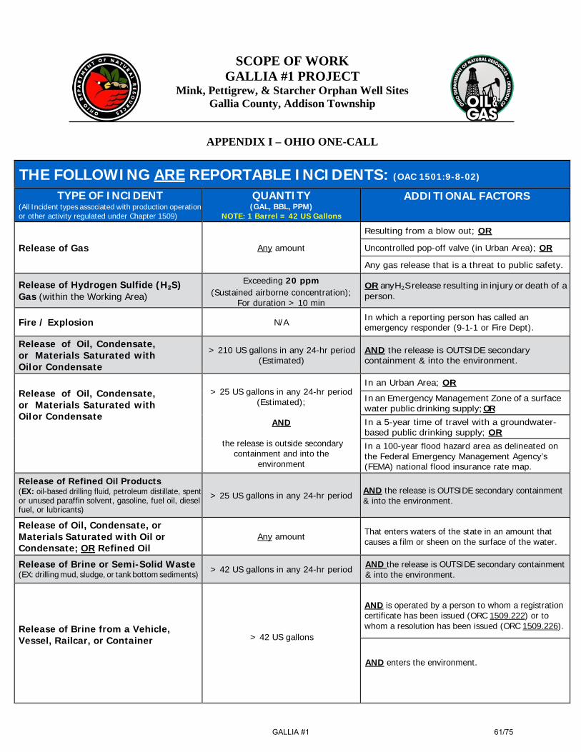
SCOPE OF WORK GALLIA #1 PROJECT
Mink, Pettigrew, & Starcher Orphan Well Sites Gallia County, Addison Township
APPENDIX I – OHIO ONE-CALL
THE FOLLOWING ARE REPORTABLE INCIDENTS: (OAC 1501:9-8-02)
TYPE OF INCIDENT (All Incident types associated with production operation or other activity regulated under Chapter 1509)
QUANTITY (GAL, BBL, PPM)
NOTE: 1 Barrel = 42 US Gallons
ADDITIONAL FACTORS
Release of Gas
Any amount Resulting from a blow out; OR Uncontrolled pop-off valve (in Urban Area); OR Any gas release that is a threat to public safety.
Release of Hydrogen Sulfide (H₂S) Gas (within the Working Area)
Exceeding 20 ppm (Sustained airborne concentration);
For duration > 10 min OR any H₂S release resulting in injury or death of a person.
Fire / Explosion N/A In which a reporting person has called an emergency responder (9-1-1 or Fire Dept).
Release of Oil, Condensate, or Materials Saturated with Oil or Condensate
> 210 US gallons in any 24-hr period (Estimated)
AND the release is OUTSIDE secondary containment & into the environment.
Release of Oil, Condensate, or Materials Saturated with Oil or Condensate
> 25 US gallons in any 24-hr period
(Estimated);
AND
the release is outside secondary containment and into the
environment
In an Urban Area; OR In an Emergency Management Zone of a surface water public drinking supply; OR In a 5-year time of travel with a groundwater- based public drinking supply; OR In a 100-year flood hazard area as delineated on the Federal Emergency Management Agency’s (FEMA) national flood insurance rate map.
Release of Refined Oil Products (EX: oil-based drilling fluid, petroleum distillate, spent or unused paraffin solvent, gasoline, fuel oil, diesel fuel, or lubricants)
> 25 US gallons in any 24-hr period
AND the release is OUTSIDE secondary containment & into the environment.
Release of Oil, Condensate, or Materials Saturated with Oil or Condensate; OR Refined Oil
Any amount That enters waters of the state in an amount that
causes a film or sheen on the surface of the water.
Release of Brine or Semi-Solid Waste (EX: drilling mud, sludge, or tank bottom sediments) > 42 US gallons in any 24-hr period AND the release is OUTSIDE secondary containment
& into the environment.
Release of Brine from a Vehicle, Vessel, Railcar, or Container
> 42 US gallons
AND is operated by a person to whom a registration certificate has been issued (ORC 1509.222) or to whom a resolution has been issued (ORC 1509.226).
AND enters the environment.
GALLIA #1
61/75

Release of Hazardous Substance (HS); Extremely Hazardous Substance (EHS); OR, Mixture or Solution including a HS or EHS.
An amount equal to or > than applicable reportable quantities listed in 40 CFR tables in any 24-hr period
List available at:
http://oilandgas.ohiodnr.gov/portals/oilgas/pdf/em ergency/list_of_lists.pdf
Code of Federal Regulations (CFR) References: HS - Appendix A 40 CFR Part 302.4 EHS - Appendix A 40 CFR Part 355
If the amount of one or more HS or EHS released is in an unknown mixture or
solution, notify when the total amount of the mixture or solution released is equal to or > than the reportable quantity for
the HS or EHS with the lowest reportable quantity
THE FOLLOWING ARE NOT REPORTABLE INCIDENTS: (OAC 1501:9-8-02 (A)(7))
1. Controlled flaring or controlled burns authorized under Chapter 1509 of the Revised Code or under 1501:9 of the Administrative Code or authorized by the terms and conditions of a permit issued under Chapter 1509 of the Revised Code;
2. Properly functioning emission control devices authorized pursuant to Revised Code Section 3704.03; 3. Subsurface detonation of perforation-guns; 4. Seismic shots; and,
5. Controlled blasting for well site construction. Date Last Edited & Printed: 9/27/2018
GALLIA #1
62/75
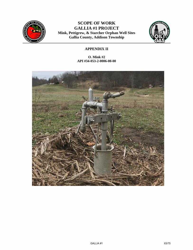
SCOPE OF WORK GALLIA #1 PROJECT
Mink, Pettigrew, & Starcher Orphan Well Sites Gallia County, Addison Township
APPENDIX II
O. Mink #2 API #34-053-2-0006-00-00
GALLIA #1
63/75
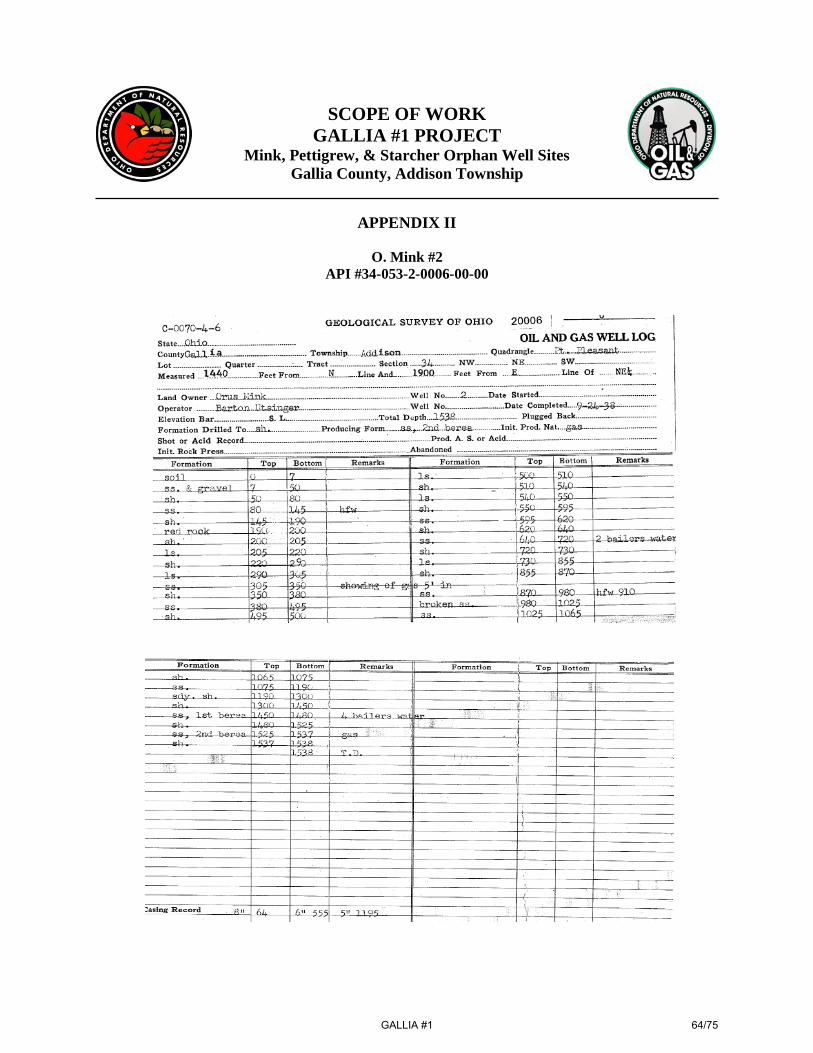
SCOPE OF WORK
GALLIA #1 PROJECT Mink, Pettigrew, & Starcher Orphan Well Sites
Gallia County, Addison Township
APPENDIX II
O. Mink #2 API #34-053-2-0006-00-00
GALLIA #1
64/75
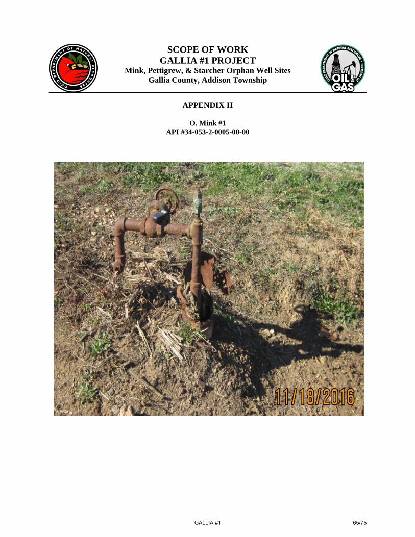
SCOPE OF WORK GALLIA #1 PROJECT
Mink, Pettigrew, & Starcher Orphan Well Sites Gallia County, Addison Township
APPENDIX II
O. Mink #1 API #34-053-2-0005-00-00
GALLIA #1
65/75
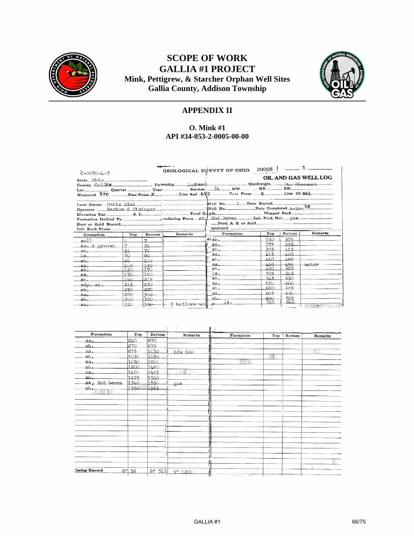
SCOPE OF WORK
GALLIA #1 PROJECT Mink, Pettigrew, & Starcher Orphan Well Sites
Gallia County, Addison Township
APPENDIX II
O. Mink #1 API #34-053-2-0005-00-00
GALLIA #1
66/75
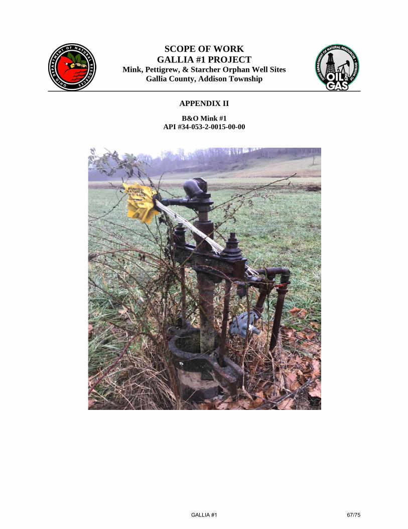
SCOPE OF WORK GALLIA #1 PROJECT
Mink, Pettigrew, & Starcher Orphan Well Sites Gallia County, Addison Township
APPENDIX II
B&O Mink #1 API #34-053-2-0015-00-00
GALLIA #1
67/75
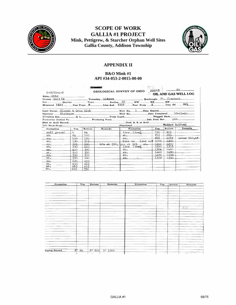
SCOPE OF WORK GALLIA #1 PROJECT
Mink, Pettigrew, & Starcher Orphan Well Sites Gallia County, Addison Township
APPENDIX II
B&O Mink #1 API #34-053-2-0015-00-00
GALLIA #1
68/75

SCOPE OF WORK GALLIA #1 PROJECT
Mink, Pettigrew, & Starcher Orphan Well Sites Gallia County, Addison Township
APPENDIX II
B&O Mink #1 API #34-053-2-0015-00-00
GALLIA #1
69/75

SCOPE OF WORK GALLIA #1 PROJECT
Mink, Pettigrew, & Starcher Orphan Well Sites Gallia County, Addison Township
APPENDIX II
Pettigrew #1 API #34-053-2-0075-00-00
GALLIA #1
70/75

SCOPE OF WORK
GALLIA #1 PROJECT Mink, Pettigrew, & Starcher Orphan Well Sites
Gallia County, Addison Township
APPENDIX II
Pettigrew #1 API #34-053-2-0075-00-00
GALLIA #1
71/75

SCOPE OF WORK GALLIA #1 PROJECT
Mink, Pettigrew, & Starcher Orphan Well Sites Gallia County, Addison Township
APPENDIX II
JH Starcher #1 API #34-053-6-0052-00-00
GALLIA #1
72/75
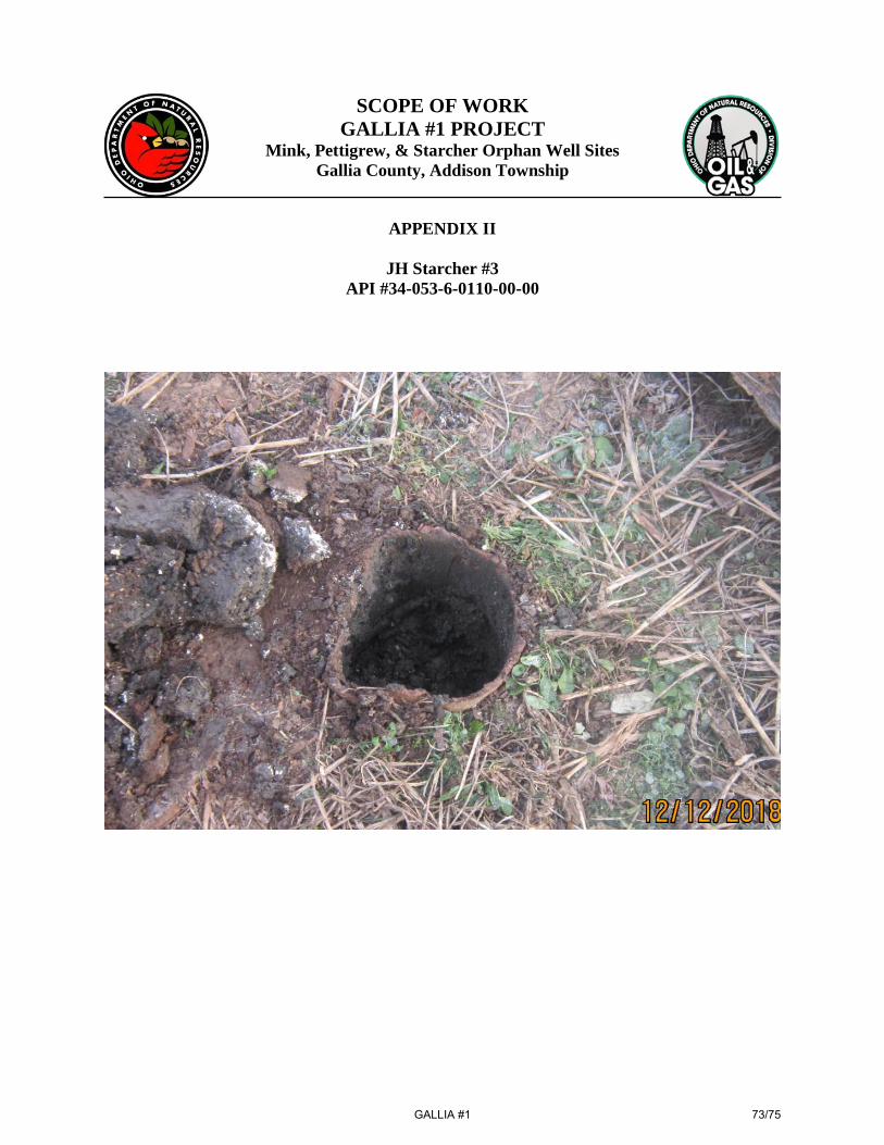
SCOPE OF WORK GALLIA #1 PROJECT
Mink, Pettigrew, & Starcher Orphan Well Sites Gallia County, Addison Township
APPENDIX II
JH Starcher #3 API #34-053-6-0110-00-00
GALLIA #1
73/75

1 Mobilization 6 Lump Sum
2 Site Safety 6 Lump Sum
3 Secondary Containment 6 Lump Sum
4 Silt Fence 1270 Linear Ft
5 Steel Road Plates 256 Square Ft
6 Road Mats 3032 Square Ft
7 No. 304 Aggregate Base 40 Ton
8 No. 57 Stone 65 Ton
9 No. 4 Stone 40 Ton
10 No. 2 Stone 50 Ton
11 Wellhead Control 5 Lump Sum
12 Wellhead Control (Pettigrew #1) 1 Lump Sum
13 Well Control Fluid 600 BBL
14 Surface Casing (7") 420 Linear Ft
15 Milling (Cement Drillout) 10 Hour
16 Logging (Gamma Ray/Bond/Caliper) 8 Each
17 Well Preparation & Plugging (O. Mink #2 & O. Mink #1) 2 Lump Sum
18 Well Preparation & Plugging (B&O Mink #1) 1 Lump Sum
19 Well Preparation & Plugging (Pettigrew #1) 1 Lump Sum
20 Well Preparation & Plugging (JH Starcher #1 & JH Starcher #3) 2 Lump Sum
21 Tubing /Drill Pipe (2.375") 1 Lump Sum
22 Tubing (1") 1 Lump Sum
23 Washover Pipe 1550 Linear Ft
24 Drilling Mud 100 Sack
25 Shooting 3 Each
26 Class "A" Cement 1820 Sack
27 Cement Mixing & Pumping 18 Each
28 Fluid Disposal 800 BBL
UIC#: ___________________________________________
29 Contaminated Material Disposal 100 Ton
Disposal Facility: _________________________________
30 Salvage Material Disposal 1 Lump Sum
31 Salvage Material Reimbursement N/A
32 Crop Damage (Corn) 803.06$ 3.6 Acre 2,891.02$
33 Crop Damage (Soybeans) 456.07$ 0.75 Acre 342.05$
34 Site Restoration (O. Mink #2 & O. Mink #1) 1 Lump Sum
35 Site Restoration (B&O Mink #1) 1 Lump Sum
36 Site Restoration (Pettigrew #1) 1 Lump Sum
37 Site Restoration (JH Starcher #3) 1 Lump Sum
38 Site Restoration (JH Starcher #1) 1 Lump Sum
39 Demobilization 6 Lump Sum
Total Encumbrance:
Scope of Work
Offer Sheet
Gallia #1 Project
Gallia County: Addison Townships
Well Names: O. Mink #2, O. Mink #1, B&O Mink #1, Pettigrew #1, JH Starcher #1 & JH Starcher #3
Do not fill out this section
UnitItem
Total
Permit Numbers: 34‐053‐2‐0006‐00‐00, 34‐053‐2‐0005‐00‐00, 34‐053‐2‐0015‐00‐00, 34‐053‐2‐0075‐00‐00, 34‐053‐6‐0052‐00‐00, 34‐053‐6‐0110‐00‐00
TD = 330'‐1580'; Cow Run & Berea Sandstone
Line
NumberUnit PriceDescription Quantity
Page 1 of 2 GALLIA #1
74/75
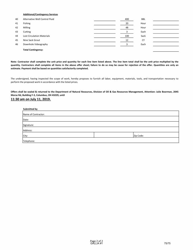
Additional/Contingency Services
40 Alternative Well Control Fluid 400 BBL
41 Fishing 20 Hour
42 Milling 48 Hour
43 Cutting 3 Each
44 Lost Circulation Materials 100 Sack
45 Nine Sack Grout 12 CY
46 Downhole Videography 3 Each
Total Contingency:
Submitted by
City:
Telephone:
Zip Code:
Note: Contractor shall complete the unit price and quantity for each line item listed above. The line item total shall be the unit price multiplied by the
quantity. Contractors shall complete all items in the above offer sheet; failure to do so may be cause for rejection of the offer. Quantities are only an
estimate. Payment shall be based on quantities satisfactorily completed.
The undersigned, having inspected the scope of work, hereby proposes to furnish all labor, equipment, materials, tools, and transportation necessary to
perform the proposed work in accordance with the listed prices.
Offers shall be sealed & returned to the Department of Natural Resources, Division of Oil & Gas Resources Management, Attention: Julie Boorman, 2045
Morse Rd, Building F‐3, Columbus, OH 43229, until
11:30 am on July 11, 2019.
Name of Contractor:
Date:
Signature:
Address:
Page 2 of 2 GALLIA #1
75/75
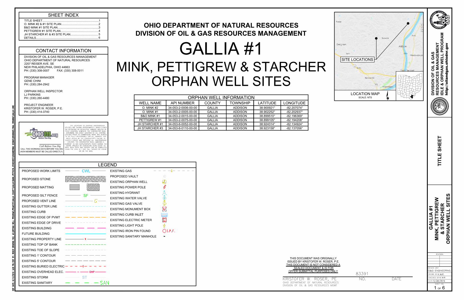
SHEET INDEX
CONTACT INFORMATION
DIVISION OF OIL & GAS RESOURCES MANAGEMENT
OHIO DEPARTMENT OF NATURAL RESOURCES
2207 REISER AVE. SE
NEW PHILADELPHIA, OHIO 44663
PH: (330) 308-0007 FAX: (330) 308-0011
PROGRAM MANAGER
GENE CHINI
PH: (330) 284-2942
ORPHAN WELL INSPECTOR
LJ PARKINS
PH: (330) 260-4480
PROJECT ENGINEER
KRISTOFER W. ROSER, P.E.
PH: (330) 414-3740
TITLE SHEET.......................................................................
O. MINK #2 & #1 SITE PLAN...............................................
B&O MINK #1 SITE PLAN....................................................
PETTIGREW #1 SITE PLAN................................................
JH STARCHER #1 & #3 SITE PLAN...................................
DETAILS..............................................................................
1
2
3
4
5
6
LOCATION MAP
N
TIT
LE
S
HE
ET
SCALE: NTS
SITE LOCATIONS
THIS DOCUMENT WAS ORIGINALLY
ISSUED BY KRISTOFER W. ROSER, P.E.
THIS DOCUMENT IS NOT CONSIDERED A
SEALED DOCUMENT & IS FOR
OFFER SUBMITTAL PURPOSES ONLY
GALLIA #1
MINK, PETTIGREW & STARCHER
OHIO DEPARTMENT OF NATURAL RESOURCES
DIVISION OF OIL & GAS RESOURCES MANAGEMENT
ORPHAN WELL SITES
1
G
AL
LIA
#
1
MIN
K, P
ET
TIG
RE
W
& S
TA
RC
HE
R
OR
PH
AN
W
EL
L S
IT
ES
htt
p:/
/oil
an
dg
as.o
hio
dn
r.g
ov
DIV
IS
IO
N O
F O
IL
&
G
AS
RE
SO
UR
CE
S M
AN
AG
EM
EN
T
ID
LE
&
O
RP
HA
N W
EL
L P
RO
GR
AM
6OF
CWLPROPOSED WORK LIMITS
EXISTING GUTTER LINE
EXISTING CURB
EXISTING BUILDING
EXISTING ORPHAN WELL
EXISTING POWER POLE
EXISTING WATER VALVE
LEGEND
EXISTING EDGE OF PVMT
EXISTING MONUMENT BOX
EXISTING CURB INLET
EXISTING SANITARY MANHOLE
EXISTING ELECTRIC METER
EXISTING HYDRANT
EXISTING LIGHT POLE
EXISTING IRON PIN FOUND
PROPOSED STONE
PROPOSED MATTING
SFPROPOSED SILT FENCE
EXISTING TOP OF BANK
EXISTING TOE OF SLOPE
EXISTING 1' CONTOUR
EXISTING 5' CONTOUR
EXISTING EDGE OF DRIVE
EXISTING PROPERTY LINE
PROPOSED VENT LINE
PROPOSED VAULT
EXISTING BURIED ELECTRIC
EXISTING OVERHEAD ELEC.
EXISTING GAS VALVE
STEXISTING STORM
EXISTING SANITARY
FUTURE BUILDING
EXISTING GAS
O. MINK #1
ORPHAN WELL INFORMATION
WELL NAME API NUMBER COUNTY TOWNSHIP
34-053-2-0005-00-00 GALLIA ADDISON
LATITUDE LONGITUDE
38.902252° -82.202937°
Call Before You DigCALL TWO WORKING DAYS BEFORE YOU DIG
(NON MEMBERS MUST BE CALLED DIRECTLY)
O. MINK #2 34-053-2-0006-00-00 GALLIA ADDISON 38.900921° -82.207074°
B&O MINK #1 34-053-2-0015-00-00 GALLIA ADDISON 38.899510° -82.196369°
PETTIGREW #1 34-053-2-0075-00-00 GALLIA ADDISON 38.899105° -82.194208°
JH STARCHER #1 34-053-6-0052-00-00 GALLIA ADDISON 38.924314° -82.134924°
JH STARCHER #3 34-053-6-0110-00-00 GALLIA ADDISON 38.923158° -82.137056°
AutoCAD SHX Text
OHIO DEPARTMENT OF NATURAL RESOURCES
AutoCAD SHX Text
DIVISION OF OIL & GAS RESOURCES MGMT
AutoCAD SHX Text
KRISTOFER W. ROSER, PENO.DATENO.DATEDATE
AutoCAD SHX Text
83391
AutoCAD SHX Text
EDIT DATE: 6/13/2019 3:38 PM EDIT BY: ROSER DRAWING FILE: M:\ORPHAN WELL PROGRAM\PROJECTS\GALLIA COUNTY\GALLIA1(MINK_PETTIGEW_STARCHER)\ENGINEERING DESIGN\DRAWINGS\FINAL DRAWING\GALLIA1.DWG6/13/2019 3:38 PM EDIT BY: ROSER DRAWING FILE: M:\ORPHAN WELL PROGRAM\PROJECTS\GALLIA COUNTY\GALLIA1(MINK_PETTIGEW_STARCHER)\ENGINEERING DESIGN\DRAWINGS\FINAL DRAWING\GALLIA1.DWG EDIT BY: ROSER DRAWING FILE: M:\ORPHAN WELL PROGRAM\PROJECTS\GALLIA COUNTY\GALLIA1(MINK_PETTIGEW_STARCHER)\ENGINEERING DESIGN\DRAWINGS\FINAL DRAWING\GALLIA1.DWGROSER DRAWING FILE: M:\ORPHAN WELL PROGRAM\PROJECTS\GALLIA COUNTY\GALLIA1(MINK_PETTIGEW_STARCHER)\ENGINEERING DESIGN\DRAWINGS\FINAL DRAWING\GALLIA1.DWG DRAWING FILE: M:\ORPHAN WELL PROGRAM\PROJECTS\GALLIA COUNTY\GALLIA1(MINK_PETTIGEW_STARCHER)\ENGINEERING DESIGN\DRAWINGS\FINAL DRAWING\GALLIA1.DWGM:\ORPHAN WELL PROGRAM\PROJECTS\GALLIA COUNTY\GALLIA1(MINK_PETTIGEW_STARCHER)\ENGINEERING DESIGN\DRAWINGS\FINAL DRAWING\GALLIA1.DWG
AutoCAD SHX Text
DRAWN BY:
AutoCAD SHX Text
CHECKED BY:
AutoCAD SHX Text
O&G ENGINEERING
AutoCAD SHX Text
DESIGN UNIT
AutoCAD SHX Text
DATE:
AutoCAD SHX Text
5/28/2019
AutoCAD SHX Text
SHEET NO.
AutoCAD SHX Text
REVISION
AutoCAD SHX Text
K.W.R.
AutoCAD SHX Text
K.W.R.
AutoCAD SHX Text
THE LOCATIONS OF EXISTING UNDERGROUND UTILITIES ARE SHOWN APPROXIMATELY, BASED EITHER ON REPORTING BY RESPECTIVE OWNERS AND/OR BY FIELD LOCATION. HOWEVER, THE CONTRACTOR SHALL DETERMINE THE EXACT LOCATION OF ALL EXISTING UTILITIES PRIOR TO COMMENCING WORK AND AGREES TO BE FULLY RESPONSIBLE FOR ALL DAMAGES THAT MIGHT OCCUR BY THE CONTRACTOR'S FAILURE TO EXACTLY LOCATE AND PRESERVE ALL UNDERGROUND UTILITIES. THE CONTRACTOR SHALL MAINTAIN A CURRENT 10 DAY OUPS/OGPUPS TICKET DURING THE ENTIRE PROJECT BY CONTACTING OUPS EVERY 10 DAYS. BOTH OUPS AND OGPUPS CAN BE COMPLETED USING THE OHIO 811 ONE CALL SERVICE BY PHONE OR ON THE WEB.

C
W
L
C
W
L
C
W
L
CW
LC
WL
CW
LC
WL
CWL
C
W
L
C
W
L
C
W
L
C
W
L
C
W
LC
WL
CW
L
C
W
L
PROPOSED WORK
LIMITS (TYP.)
B
U
L
L
A
V
IL
L
E
P
IK
E
(C
.R
. 3
)
O. MINK #1 ORPHAN WELL
TO BE PLUGGED PER THE "PLUGGING PLAN"
API No.34-053-2-0005-00-00
N= 328754.74, E= 2053040.76, EL= 567.77
LAT= 38.902252°, LONG= -82.202937°
PROPOSED INGRESS/EGRESS POINT
N=329019.63, E=2053068.44
LAT=38.902979°, LONG=-82.202837°
PROPOSED TEMPORARY ACCESS DRIVE
SEE DETAIL SHEET 6
NO. 2 STONE: ±18 TONS
NO. 304 AGGREGATE: ±12 TONS
SF
SF
S
F
S
F
SF
SF
S
F
S
F
SF
EXISTING GAS MAIN
DO NOT DISTURB
EXISTING BOX CULVERT
EXISTING DRAINAGE DITCH
DO NOT DISTURB
PROPOSED ABSORBENT BOOM
WITH HARD BOOM BACKUP
(±12 L.F. EACH) PER LINE ITEM
"SITE SAFETY"
EXISTING TOE OF
SLOPE (TYP.)
EXISTING TOP OF
BANK (TYP.)
C
W
L
C
W
L
CW
L
C
W
L
C
W
L
C
W
L
C
W
L
CWL
CWL
CW
L
CW
L
CW
L
CW
L
CW
LC
W
L
C
W
L
CW
L
CW
L
CW
L
CW
L
CW
L
EXISTING DEPRESSION TO BE FILLED
WITH ONSITE EARTHWORK. INCIDENTAL
TO LINE ITEM "MOBILIZATION"
EXISTING GAS LINE TO BE REMOVED
TO O. MINK #2 WELL (±1470 L.F.) PER LINE ITEM
"SALVAGE MATERIAL DISPOSAL"
PROPOSED SILT FENCE
±300 LF
EXISTING GAS LINE TO BE REMOVED (±35 L.F.)
PER LINE ITEM "SALVAGE MATERIAL DISPOSAL"
CW
L
CW
LC
W
L
CW
L
CW
L
CW
L
CW
L
CW
L
C
W
L
CW
L
C
W
L
C
W
L
C
W
L
C
W
L
EXISTING TOP OF
BANK (TYP.)
BU
LLA
VIL
LE
PIK
E (C
.R. 3
)
PROPOSED WORK
LIMITS (TYP.)
PROPOSED INGRESS/EGRESS POINT
N=328866.33, E=2051757.31
LAT=38.902570°, LONG=-82.207446°
PROPOSED TEMPORARY ACCESS DRIVE
SEE DETAIL SHEET 6
NO. 2 STONE: ±25 TONS
NO. 304 AGGREGATE: ±12 TONS
EXISTING GAS MAIN
DO NOT DISTURB
EXISTING WET AREA
TO BE AVOIDED
EXISTING DRAINAGE DITCH
DO NOT DISTURB
EXISTING GAS LINE TO BE REMOVED
TO O. MINK #1 WELL (±1470 L.F.) PER LINE ITEM
"SALVAGE MATERIAL DISPOSAL"
PROPOSED ROAD MATS, 256 SQ. FT.
TO BE UTILIZED FOR DITCH CROSSING
S
F
S
F
S
F
S
F
CW
LC
WL
CW
LC
WL
CW
LC
WL
CW
LC
WL
CW
LC
WL
CW
LC
WL
CWL CWL
C
W
L
C
W
L
C
W
L
C
W
L
C
W
L
C
W
L
CW
L
C
W
L
C
W
L
C
W
L
C
W
L
PROPOSED ROAD MATS, 256 SQ. FT.
TO BE UTILIZED FOR DITCH CROSSING
EXISTING TOP OF
BANK (TYP.)
EXISTING TOE OF
SLOPE (TYP.)
O. MINK #2 ORPHAN WELL
TO BE PLUGGED PER THE "PLUGGING PLAN"
API No.34-053-2-0006-00-00
N= 328266.06, E= 2051865.14, EL= 570.14
LAT= 38.900921°, LONG= -82.207074°
PROPOSED SILT
FENCE ±260 L.F.
EXISTING DRAINAGE DITCH
DO NOT DISTURB
EXISTING DRIP TO BE REMOVED
PER LINE ITEM "SALVAGE
MATERIAL DISPOSAL"
C
A
M
P
A
IG
N
C
R
E
E
K
EXISTING TOP OF
BANK (TYP.)
PROPOSED STEEL ROAD PLATES, 128 SQ. FT.
TO BE UTILIZED FOR UTILITY CROSSING
EXISTING STEEL & PLASTIC
FLOW LINE TO BE REMOVED
(±680 L.F. EACH) PER LINE ITEM
"SALVAGE MATERIAL DISPOSAL"
DO NOT ENCROACH WITHIN
10' OF EXISTING GAS MAIN
G
AL
LIA
#
1
MIN
K, P
ET
TIG
RE
W
& S
TA
RC
HE
R
OR
PH
AN
W
EL
L S
IT
ES
htt
p:/
/oil
an
dg
as.o
hio
dn
r.g
ov
DIV
IS
IO
N O
F O
IL
&
G
AS
RE
SO
UR
CE
S M
AN
AG
EM
EN
T
ID
LE
&
O
RP
HA
N W
EL
L P
RO
GR
AM
6OF
BAR SCALE
0' 20' 40' 60'
MA
GN
ET
IC
O. M
IN
K #
2 &
#
1
SIT
E P
LA
N
2
BAR SCALE
0' 40' 80' 120'
MA
GN
ET
IC
O. MINK #2 SITE PLAN
SCALE:1"=80'
O. MINK #1 SITE PLAN
SCALE:1"=40'
FERTILIZER
ESTIMATED SITE RESTORATION QUANTITIES
COMPONENT RATE QUANTITY
SEED
MULCH
N/A
N/A
100 LBS/1000 SF 300 BALES
-
-
CROP DAMAGE N/A 3.6 ACRES
NOTES:
1) UTILITY LINES AND APPURTENANCES ARE SHOWN AS LOCATED IN THE
FIELD AND/OR AS REPORTED BY THE RESPECTIVE OWNERS. NEITHER
THE NUMBER, TYPE, SIZE, OR LOCATION CAN BE GUARANTEED, AND IT IS
THEREFORE, THE RESPONSIBILITY OF THE CONTRACTOR TO VERIFY ALL
UTILITY LOCATIONS.
2) THE HORIZONTAL DATUM IS BASED ON NAD83 (2011) OHIO STATE
PLANE SOUTH 3402, AND THE VERTICAL DATUM IS BASED ON NAVD88
GEOID 12A CORS DERIVED.
3) PHOTO IMAGE DATA OBTAINED FROM OGRIP ON MAY OF 2019.
4) ROAD MATS SHALL BE USED FOR TEMPORARY CONSTRUCTION
ACCESS TO TRAVERSE DRAINAGE COURSES.
5) THE WORK LIMITS AND CORRESPONDING SEDIMENT CONTROLS
ALONG THE CREEK WILL BE DETERMINED IN THE FIELD BY THE DIVISION
THROUGHOUT CONSTRUCTION.
6) SEDIMENT CONTROLS SHALL BE PLACED AT THE DISCRETION OF THE
DIVISION.
AutoCAD SHX Text
570
AutoCAD SHX Text
DRAWN BY:
AutoCAD SHX Text
CHECKED BY:
AutoCAD SHX Text
O&G ENGINEERING
AutoCAD SHX Text
DESIGN UNIT
AutoCAD SHX Text
DATE:
AutoCAD SHX Text
5/28/2019
AutoCAD SHX Text
SHEET NO.
AutoCAD SHX Text
REVISION
AutoCAD SHX Text
K.W.R.
AutoCAD SHX Text
K.W.R.
AutoCAD SHX Text
EDIT DATE: 6/13/2019 3:38 PM EDIT BY: ROSER DRAWING FILE: M:\ORPHAN WELL PROGRAM\PROJECTS\GALLIA COUNTY\GALLIA1(MINK_PETTIGEW_STARCHER)\ENGINEERING DESIGN\DRAWINGS\FINAL DRAWING\GALLIA1.DWG6/13/2019 3:38 PM EDIT BY: ROSER DRAWING FILE: M:\ORPHAN WELL PROGRAM\PROJECTS\GALLIA COUNTY\GALLIA1(MINK_PETTIGEW_STARCHER)\ENGINEERING DESIGN\DRAWINGS\FINAL DRAWING\GALLIA1.DWG EDIT BY: ROSER DRAWING FILE: M:\ORPHAN WELL PROGRAM\PROJECTS\GALLIA COUNTY\GALLIA1(MINK_PETTIGEW_STARCHER)\ENGINEERING DESIGN\DRAWINGS\FINAL DRAWING\GALLIA1.DWGROSER DRAWING FILE: M:\ORPHAN WELL PROGRAM\PROJECTS\GALLIA COUNTY\GALLIA1(MINK_PETTIGEW_STARCHER)\ENGINEERING DESIGN\DRAWINGS\FINAL DRAWING\GALLIA1.DWG DRAWING FILE: M:\ORPHAN WELL PROGRAM\PROJECTS\GALLIA COUNTY\GALLIA1(MINK_PETTIGEW_STARCHER)\ENGINEERING DESIGN\DRAWINGS\FINAL DRAWING\GALLIA1.DWGM:\ORPHAN WELL PROGRAM\PROJECTS\GALLIA COUNTY\GALLIA1(MINK_PETTIGEW_STARCHER)\ENGINEERING DESIGN\DRAWINGS\FINAL DRAWING\GALLIA1.DWG

C
W
L
C
W
L
C
W
L
C
W
L
C
W
L
C
W
L
C
W
L
C
W
L
C
W
L
C
W
L
C
W
L
C
W
L
C
W
L
C
W
L
C
W
L
CW
L
C
W
L
C
W
L
C
W
L
C
W
L
C
W
L
C
W
L
C
W
LC
W
L
C
W
L
C
W
L
C
W
L
C
W
L
C
W
L
C
W
L
C
W
L
EXISTING GAS MAIN
DO NOT DISTURB
PROPOSED WORK
LIMITS (TYP.)
B
U
L
L
A
V
I
L
L
E
P
I
K
E
(
C
.
R
.
3
)
B&O MINK #1 ORPHAN WELL
TO BE PLUGGED PER THE "PLUGGING PLAN"
API No.34-053-2-0015-00-00
N= 327762.36, E= 2054913.21, EL= 564.96
LAT= 38.899510°, LONG= -82.196369°
PROPOSED INGRESS/EGRESS POINT
N=328172.95, E=2054666.70
LAT=38.900640°, LONG=-82.197231°
EXISTING GAS MAIN
DO NOT DISTURB
EXISTING LOW SPOT
TO BE AVOIDED
PROPOSED SILT FENCE
±260 LF
EXISTING 12" Ø CULVERT
CAUTION: EXISTING OVERHEAD
UTILITY (±25' CLEARANCE)
CAUTION: EXISTING OVERHEAD
UTILITY (±25' CLEARANCE)
S
F
S
F
S
F
SF
SF
EXISTING TOP OF
BANK (TYP.)
CA
MP
AIG
N C
RE
EK
EXISTING TOP OF
BANK (TYP.)
EXISTING UTILITY RIGHT OF WAY
DO NOT ENCROACH
EXISTING GAS LINE TO BE REMOVED
PER LINE ITEM "SALVAGE MATERIAL DISPOSAL"
(±95 L.F.)
PROPOSED STEEL ROAD PLATES, 128 SQ. FT.
TO BE UTILIZED FOR UTILITY CROSSING
PROPOSED NO.57 STONE OVERLAY
SEE DETAIL SHEET 6
NO. 57 STONE: ±18 TONS
G
AL
LIA
#
1
MIN
K, P
ET
TIG
RE
W
& S
TA
RC
HE
R
OR
PH
AN
W
EL
L S
IT
ES
htt
p:/
/oil
an
dg
as.o
hio
dn
r.g
ov
DIV
IS
IO
N O
F O
IL
&
G
AS
RE
SO
UR
CE
S M
AN
AG
EM
EN
T
ID
LE
&
O
RP
HA
N W
EL
L P
RO
GR
AM
6OF
BAR SCALE
0' 25' 50' 75'
MA
GN
ET
IC
B&
O M
IN
K #
1
SIT
E P
LA
N
3
NOTES:
1) UTILITY LINES AND APPURTENANCES ARE SHOWN AS LOCATED IN THE FIELD
AND/OR AS REPORTED BY THE RESPECTIVE OWNERS. NEITHER THE NUMBER,
TYPE, SIZE, OR LOCATION CAN BE GUARANTEED, AND IT IS THEREFORE, THE
RESPONSIBILITY OF THE CONTRACTOR TO VERIFY ALL UTILITY LOCATIONS.
2) THE HORIZONTAL DATUM IS BASED ON NAD83 (2011) OHIO STATE PLANE SOUTH
3402, AND THE VERTICAL DATUM IS BASED ON NAVD88 GEOID 12A CORS DERIVED.
3) PHOTO IMAGE DATA OBTAINED FROM OGRIP ON MAY OF 2019.
4) THE WORK LIMITS AND CORRESPONDING SEDIMENT CONTROLS ALONG THE
CREEK WILL BE DETERMINED IN THE FIELD BY THE DIVISION THROUGHOUT
CONSTRUCTION.
5) SEDIMENT CONTROLS SHALL BE PLACED AT THE DISCRETION OF THE DIVISION.
FERTILIZER
ESTIMATED SITE RESTORATION QUANTITIES
COMPONENT RATE QUANTITY
SEED
MULCH
20 LBS/1000 SF
75 LBS/1 ACRE
100 LBS/1000 SF 45 BALES
40 LBS
450 LBS
AutoCAD SHX Text
DRAWN BY:
AutoCAD SHX Text
CHECKED BY:
AutoCAD SHX Text
O&G ENGINEERING
AutoCAD SHX Text
DESIGN UNIT
AutoCAD SHX Text
DATE:
AutoCAD SHX Text
5/28/2019
AutoCAD SHX Text
SHEET NO.
AutoCAD SHX Text
REVISION
AutoCAD SHX Text
K.W.R.
AutoCAD SHX Text
K.W.R.
AutoCAD SHX Text
EDIT DATE: 6/13/2019 3:38 PM EDIT BY: ROSER DRAWING FILE: M:\ORPHAN WELL PROGRAM\PROJECTS\GALLIA COUNTY\GALLIA1(MINK_PETTIGEW_STARCHER)\ENGINEERING DESIGN\DRAWINGS\FINAL DRAWING\GALLIA1.DWG6/13/2019 3:38 PM EDIT BY: ROSER DRAWING FILE: M:\ORPHAN WELL PROGRAM\PROJECTS\GALLIA COUNTY\GALLIA1(MINK_PETTIGEW_STARCHER)\ENGINEERING DESIGN\DRAWINGS\FINAL DRAWING\GALLIA1.DWG EDIT BY: ROSER DRAWING FILE: M:\ORPHAN WELL PROGRAM\PROJECTS\GALLIA COUNTY\GALLIA1(MINK_PETTIGEW_STARCHER)\ENGINEERING DESIGN\DRAWINGS\FINAL DRAWING\GALLIA1.DWGROSER DRAWING FILE: M:\ORPHAN WELL PROGRAM\PROJECTS\GALLIA COUNTY\GALLIA1(MINK_PETTIGEW_STARCHER)\ENGINEERING DESIGN\DRAWINGS\FINAL DRAWING\GALLIA1.DWG DRAWING FILE: M:\ORPHAN WELL PROGRAM\PROJECTS\GALLIA COUNTY\GALLIA1(MINK_PETTIGEW_STARCHER)\ENGINEERING DESIGN\DRAWINGS\FINAL DRAWING\GALLIA1.DWGM:\ORPHAN WELL PROGRAM\PROJECTS\GALLIA COUNTY\GALLIA1(MINK_PETTIGEW_STARCHER)\ENGINEERING DESIGN\DRAWINGS\FINAL DRAWING\GALLIA1.DWG
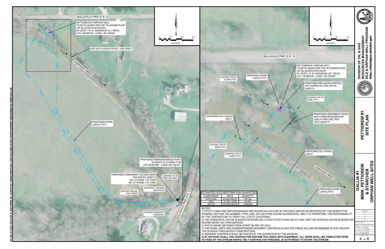
C
W
L
CWL
C
W
L
C
W
L
C
W
L
C
W
L
C
W
L
C
W
L
C
W
L
C
W
L
C
W
L
C
W
L
C
W
L
CW
LC
WL
CW
L
C
W
L
C
W
L
C
W
L
C
W
L
C
W
L
CW
L
C
W
L
BULLAVILLE PIKE (C.R. 3)
C
A
M
P
A
I
G
N
C
R
E
E
K
PETTIGREW #1 ORPHAN WELL
TO BE PLUGGED PER THE "PLUGGING PLAN"
API No.34-053-2-0075-00-00
N= 327617.10, E= 2055528.82, EL= 555.84
LAT= 38.899105°, LONG= -82.194208°
SEE SITE PLAN EXTENTS, THIS SHEET
PROPOSED WORK
LIMITS (TYP.)
PROPOSED INGRESS/EGRESS POINT
N=326874.75, E=2056117.98
LAT=38.897062°, LONG=-82.192147°
PROPOSED PERMANENT ACCESS DRIVE
SEE DETAIL SHEET 6
NO. 4 STONE: ±18 TONS
NO. 57 STONE: ±12 TONS
EXISTING CONCRETE
HEADWALL
EXISTING 18" Ø
HDPE CULVERT
EXISTING 4" WOODEN
GATE POST
EXISTING GRAVEL
FIELD DRIVE
B
U
L
L
A
V
I
L
L
E
P
I
K
E
(
C
.
R
.
3
)
C
W
L
C
W
L
C
W
L
C
W
L
C
W
L
C
W
L
C
W
L C
W
L
C
W
L
C
W
L
C
W
L
CW
L
BULLAVILLE PIKE (C.R. 3)
PETTIGREW #1 ORPHAN WELL
TO BE PLUGGED PER THE "PLUGGING PLAN"
API No.34-053-2-0075-00-00
N= 327617.10, E= 2055528.82, EL= 555.84
LAT= 38.899105°, LONG= -82.194208°
EXISTING TOP OF
BANK (TYP.)
PROPOSED ABSORBENT BOOM
WITH HARD BOOM BACKUP
(±28 LF) PER LINE ITEM
"SITE SAFETY"
PROPOSED SILT FENCE
±80 LF
EXISTING TOP OF
BANK (TYP.)
EXISTING TOE OF
SLOPE (TYP.)
EXISTING TOE OF
SLOPE (TYP.)
PROPOSED WORK
LIMITS (TYP.)
PROPOSED WORK
LIMITS (TYP.)
S
F
S
F
S
F
PROPOSED SILT FENCE
±30 LF
PROPOSED WELLHEAD CONTROL
(PETTIGREW #1), SEE DETAIL
SHEET 6
C
A
M
P
A
I
G
N
C
R
E
E
K
G
AL
LIA
#
1
MIN
K, P
ET
TIG
RE
W
& S
TA
RC
HE
R
OR
PH
AN
W
EL
L S
IT
ES
htt
p:/
/oil
an
dg
as.o
hio
dn
r.g
ov
DIV
IS
IO
N O
F O
IL
&
G
AS
RE
SO
UR
CE
S M
AN
AG
EM
EN
T
ID
LE
&
O
RP
HA
N W
EL
L P
RO
GR
AM
6OF
BAR SCALE
0' 15' 30' 45'
MA
GN
ET
IC
PE
TT
IG
RE
W #
1
SIT
E P
LA
N
4
NOTES:
1) UTILITY LINES AND APPURTENANCES ARE SHOWN AS LOCATED IN THE FIELD AND/OR AS REPORTED BY THE RESPECTIVE
OWNERS. NEITHER THE NUMBER, TYPE, SIZE, OR LOCATION CAN BE GUARANTEED, AND IT IS THEREFORE, THE RESPONSIBILITY
OF THE CONTRACTOR TO VERIFY ALL UTILITY LOCATIONS.
2) THE HORIZONTAL DATUM IS BASED ON NAD83 (2011) OHIO STATE PLANE SOUTH 3402, AND THE VERTICAL DATUM IS BASED ON
NAVD88 GEOID 12A CORS DERIVED.
3) PHOTO IMAGE OBTAINED FROM OGRIP ON MAY OF 2019.
4) THE WORK LIMITS AND CORRESPONDING SEDIMENT CONTROLS ALONG THE CREEK WILL BE DETERMINED IN THE FIELD BY
THE DIVISION THROUGHOUT CONSTRUCTION.
5) SEDIMENT CONTROLS SHALL BE PLACED AT THE DISCRETION OF THE DIVISION.
6) AT NO POINT SHALL THE CONTRACTOR DISTURB THE CREEK WITH EQUIPMENT. ALL WORK SHALL BE COMPLETED FROM
OUTSIDE OF THE STREAM BANKS. ONLY CONTRACTOR PERSONEL IS AUTHORIZED TO ENTER THE STREAM.
BAR SCALE
0' 50' 100' 150'
MA
GN
ET
IC
FERTILIZER
ESTIMATED SITE RESTORATION QUANTITIES
COMPONENT RATE QUANTITY
SEED
MULCH
20 LBS/1000 SF
75 LBS/1 ACRE
100 LBS/1000 SF 75 BALES
65 LBS
760 LBS
AutoCAD SHX Text
560
AutoCAD SHX Text
560
AutoCAD SHX Text
560
AutoCAD SHX Text
560
AutoCAD SHX Text
560
AutoCAD SHX Text
DRAWN BY:
AutoCAD SHX Text
CHECKED BY:
AutoCAD SHX Text
O&G ENGINEERING
AutoCAD SHX Text
DESIGN UNIT
AutoCAD SHX Text
DATE:
AutoCAD SHX Text
5/28/2019
AutoCAD SHX Text
SHEET NO.
AutoCAD SHX Text
REVISION
AutoCAD SHX Text
K.W.R.
AutoCAD SHX Text
K.W.R.
AutoCAD SHX Text
EDIT DATE: 6/13/2019 3:38 PM EDIT BY: ROSER DRAWING FILE: M:\ORPHAN WELL PROGRAM\PROJECTS\GALLIA COUNTY\GALLIA1(MINK_PETTIGEW_STARCHER)\ENGINEERING DESIGN\DRAWINGS\FINAL DRAWING\GALLIA1.DWG6/13/2019 3:38 PM EDIT BY: ROSER DRAWING FILE: M:\ORPHAN WELL PROGRAM\PROJECTS\GALLIA COUNTY\GALLIA1(MINK_PETTIGEW_STARCHER)\ENGINEERING DESIGN\DRAWINGS\FINAL DRAWING\GALLIA1.DWG EDIT BY: ROSER DRAWING FILE: M:\ORPHAN WELL PROGRAM\PROJECTS\GALLIA COUNTY\GALLIA1(MINK_PETTIGEW_STARCHER)\ENGINEERING DESIGN\DRAWINGS\FINAL DRAWING\GALLIA1.DWGROSER DRAWING FILE: M:\ORPHAN WELL PROGRAM\PROJECTS\GALLIA COUNTY\GALLIA1(MINK_PETTIGEW_STARCHER)\ENGINEERING DESIGN\DRAWINGS\FINAL DRAWING\GALLIA1.DWG DRAWING FILE: M:\ORPHAN WELL PROGRAM\PROJECTS\GALLIA COUNTY\GALLIA1(MINK_PETTIGEW_STARCHER)\ENGINEERING DESIGN\DRAWINGS\FINAL DRAWING\GALLIA1.DWGM:\ORPHAN WELL PROGRAM\PROJECTS\GALLIA COUNTY\GALLIA1(MINK_PETTIGEW_STARCHER)\ENGINEERING DESIGN\DRAWINGS\FINAL DRAWING\GALLIA1.DWG
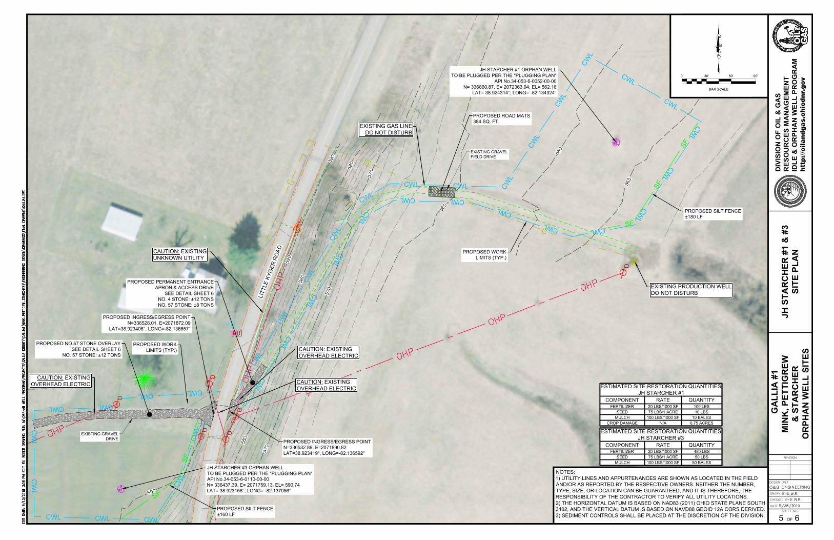
C
W
L
C
W
L
C
W
L
C
W
L
C
W
L
CWL
CWL
C
W
L
C
W
L
C
W
L
C
W
L
C
W
L
C
W
L
C
W
L
C
W
L
C
W
L
C
W
L
C
W
L
C
W
L
CWL
CWL
C
W
L
C
W
L
C
W
L
C
W
L
C
W
L
CW
L
CW
L
CWL
CWL
CW
LC
WL
CWL
CWL
CWL
C
W
L
C
W
L
PROPOSED WORK
LIMITS (TYP.)
L
I
T
T
L
E
K
Y
G
E
R
R
O
A
D
JH STARCHER #1 ORPHAN WELL
TO BE PLUGGED PER THE "PLUGGING PLAN"
API No.34-053-6-0052-00-00
N= 336860.87, E= 2072363.94, EL= 562.16
LAT= 38.924314°, LONG= -82.134924°
PROPOSED SILT FENCE
±180 LF
JH STARCHER #3 ORPHAN WELL
TO BE PLUGGED PER THE "PLUGGING PLAN"
API No.34-053-6-0110-00-00
N= 336437.39, E= 2071759.13, EL= 590.74
LAT= 38.923158°, LONG= -82.137056°
S
F
S
F
S
F
PROPOSED WORK
LIMITS (TYP.)
EXISTING PRODUCTION WELL
DO NOT DISTURB
CAUTION: EXISTING
UNKNOWN UTILITY
PROPOSED NO.57 STONE OVERLAY
SEE DETAIL SHEET 6
NO. 57 STONE: ±12 TONS
EXISTING GRAVEL
DRIVE
CAUTION: EXISTING
OVERHEAD ELECTRIC
PROPOSED INGRESS/EGRESS POINT
N=336528.01, E=2071872.09
LAT=38.923406°, LONG=-82.136657°
PROPOSED INGRESS/EGRESS POINT
N=336532.89, E=2071890.82
LAT=38.923419°, LONG=-82.136592°
CAUTION: EXISTING
OVERHEAD ELECTRIC
CAUTION: EXISTING
OVERHEAD ELECTRIC
PROPOSED PERMANENT ENTRANCE
APRON & ACCESS DRIVE
SEE DETAIL SHEET 6
NO. 4 STONE: ±12 TONS
NO. 57 STONE: ±8 TONS
S
F
S
F
PROPOSED SILT FENCE
±160 LF
EXISTING GAS LINE
DO NOT DISTURB
EXISTING GRAVEL
FIELD DRIVE
PROPOSED ROAD MATS
384 SQ. FT.
G
AL
LIA
#
1
MIN
K, P
ET
TIG
RE
W
& S
TA
RC
HE
R
OR
PH
AN
W
EL
L S
IT
ES
htt
p:/
/oil
an
dg
as.o
hio
dn
r.g
ov
DIV
IS
IO
N O
F O
IL
&
G
AS
RE
SO
UR
CE
S M
AN
AG
EM
EN
T
ID
LE
&
O
RP
HA
N W
EL
L P
RO
GR
AM
6OF
BAR SCALE
0' 30' 60' 90'
MA
GN
ET
IC
JH
S
TA
RC
HE
R #
1 &
#
3
SIT
E P
LA
N
5
NOTES:
1) UTILITY LINES AND APPURTENANCES ARE SHOWN AS LOCATED IN THE FIELD
AND/OR AS REPORTED BY THE RESPECTIVE OWNERS. NEITHER THE NUMBER,
TYPE, SIZE, OR LOCATION CAN BE GUARANTEED, AND IT IS THEREFORE, THE
RESPONSIBILITY OF THE CONTRACTOR TO VERIFY ALL UTILITY LOCATIONS.
2) THE HORIZONTAL DATUM IS BASED ON NAD83 (2011) OHIO STATE PLANE SOUTH
3402, AND THE VERTICAL DATUM IS BASED ON NAVD88 GEOID 12A CORS DERIVED.
3) SEDIMENT CONTROLS SHALL BE PLACED AT THE DISCRETION OF THE DIVISION.
FERTILIZER
ESTIMATED SITE RESTORATION QUANTITIES
JH STARCHER #3
COMPONENT RATE QUANTITY
SEED
MULCH
20 LBS/1000 SF
75 LBS/1 ACRE
100 LBS/1000 SF 50 BALES
50 LBS
480 LBS
FERTILIZER
ESTIMATED SITE RESTORATION QUANTITIES
JH STARCHER #1
COMPONENT RATE QUANTITY
SEED
MULCH
20 LBS/1000 SF
75 LBS/1 ACRE
100 LBS/1000 SF 10 BALES
10 LBS
100 LBS
CROP DAMAGE N/A 0.75 ACRES
AutoCAD SHX Text
590
AutoCAD SHX Text
580
AutoCAD SHX Text
570
AutoCAD SHX Text
580
AutoCAD SHX Text
570
AutoCAD SHX Text
580
AutoCAD SHX Text
570
AutoCAD SHX Text
590
AutoCAD SHX Text
590
AutoCAD SHX Text
560
AutoCAD SHX Text
560
AutoCAD SHX Text
560
AutoCAD SHX Text
DRAWN BY:
AutoCAD SHX Text
CHECKED BY:
AutoCAD SHX Text
O&G ENGINEERING
AutoCAD SHX Text
DESIGN UNIT
AutoCAD SHX Text
DATE:
AutoCAD SHX Text
5/28/2019
AutoCAD SHX Text
SHEET NO.
AutoCAD SHX Text
REVISION
AutoCAD SHX Text
K.W.R.
AutoCAD SHX Text
K.W.R.
AutoCAD SHX Text
EDIT DATE: 6/13/2019 3:38 PM EDIT BY: ROSER DRAWING FILE: M:\ORPHAN WELL PROGRAM\PROJECTS\GALLIA COUNTY\GALLIA1(MINK_PETTIGEW_STARCHER)\ENGINEERING DESIGN\DRAWINGS\FINAL DRAWING\GALLIA1.DWG6/13/2019 3:38 PM EDIT BY: ROSER DRAWING FILE: M:\ORPHAN WELL PROGRAM\PROJECTS\GALLIA COUNTY\GALLIA1(MINK_PETTIGEW_STARCHER)\ENGINEERING DESIGN\DRAWINGS\FINAL DRAWING\GALLIA1.DWG EDIT BY: ROSER DRAWING FILE: M:\ORPHAN WELL PROGRAM\PROJECTS\GALLIA COUNTY\GALLIA1(MINK_PETTIGEW_STARCHER)\ENGINEERING DESIGN\DRAWINGS\FINAL DRAWING\GALLIA1.DWGROSER DRAWING FILE: M:\ORPHAN WELL PROGRAM\PROJECTS\GALLIA COUNTY\GALLIA1(MINK_PETTIGEW_STARCHER)\ENGINEERING DESIGN\DRAWINGS\FINAL DRAWING\GALLIA1.DWG DRAWING FILE: M:\ORPHAN WELL PROGRAM\PROJECTS\GALLIA COUNTY\GALLIA1(MINK_PETTIGEW_STARCHER)\ENGINEERING DESIGN\DRAWINGS\FINAL DRAWING\GALLIA1.DWGM:\ORPHAN WELL PROGRAM\PROJECTS\GALLIA COUNTY\GALLIA1(MINK_PETTIGEW_STARCHER)\ENGINEERING DESIGN\DRAWINGS\FINAL DRAWING\GALLIA1.DWG
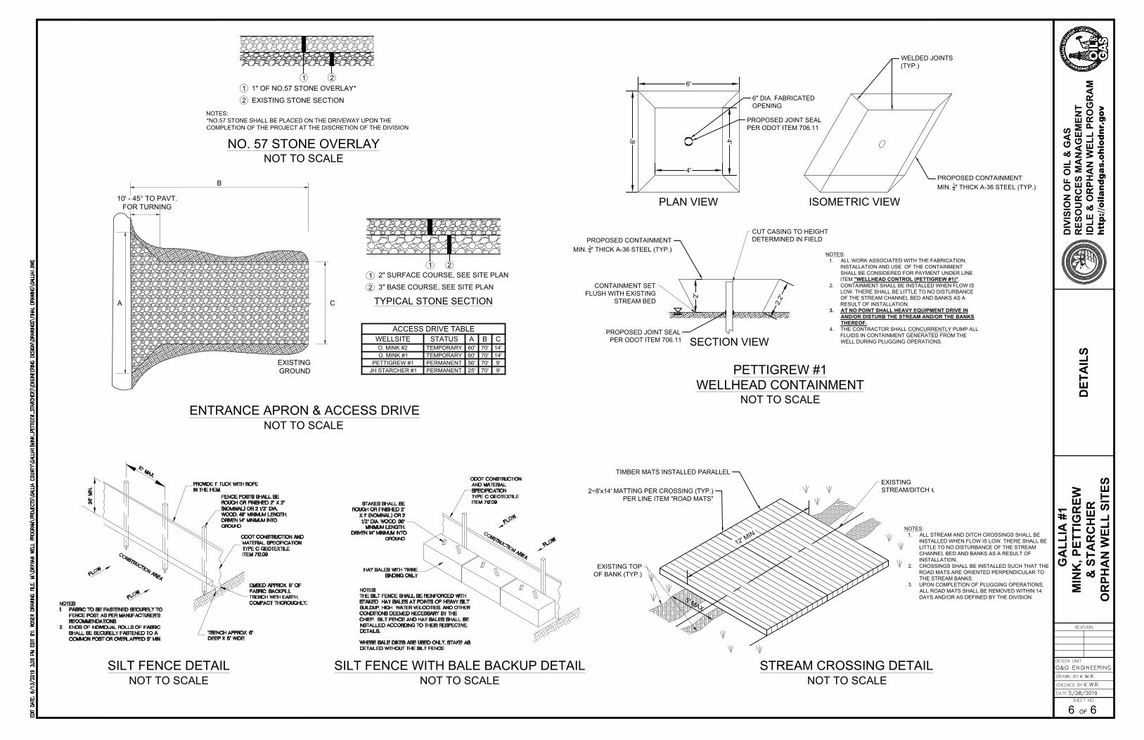
1 2
EXISTING STONE SECTION2
1 1" OF NO.57 STONE OVERLAY*
NOT TO SCALE
NOTES:
*NO.57 STONE SHALL BE PLACED ON THE DRIVEWAY UPON THE
COMPLETION OF THE PROJECT AT THE DISCRETION OF THE DIVISION
NO. 57 STONE OVERLAY
NOT TO SCALE
ENTRANCE APRON & ACCESS DRIVE
NOT TO SCALE
STREAM CROSSING DETAIL
EXISTING
STREAM/DITCH ℄
1
2
'
M
I
N
2~8'x14' MATTING PER CROSSING (TYP.)
PER LINE ITEM "ROAD MATS"
5
'
M
A
X
.
EXISTING TOP
OF BANK (TYP.)
TIMBER MATS INSTALLED PARALLEL
NOTES:
1. ALL STREAM AND DITCH CROSSINGS SHALL BE
INSTALLED WHEN FLOW IS LOW. THERE SHALL BE
LITTLE TO NO DISTURBANCE OF THE STREAM
CHANNEL BED AND BANKS AS A RESULT OF
INSTALLATION,
2. CROSSINGS SHALL BE INSTALLED SUCH THAT THE
ROAD MATS ARE ORIENTED PERPENDICULAR TO
THE STREAM BANKS.
3. UPON COMPLETION OF PLUGGING OPERATIONS,
ALL ROAD MATS SHALL BE REMOVED WITHIN 14
DAYS AND/OR AS DEFINED BY THE DIVISION.
NOT TO SCALE
SILT FENCE DETAIL
NOT TO SCALE
SILT FENCE WITH BALE BACKUP DETAIL
B
C
EXISTING
GROUND
10' - 45° TO PAVT.
FOR TURNING
A
O. MINK #2
ACCESS DRIVE TABLE
WELLSITE STATUS
O. MINK #1
PETTIGREW #1
JH STARCHER #1
TEMPORARY
PERMANENT
A
60'
60'
56'
25'
B
70'
70'
70'
70'
C
14'
14'
9'
9'
1
3" BASE COURSE, SEE SITE PLAN2
1
2" SURFACE COURSE, SEE SITE PLAN
2
TYPICAL STONE SECTION
NOT TO SCALE
WELLHEAD CONTAINMENT
PETTIGREW #1
PROPOSED CONTAINMENT
MIN.
1
4
" THICK A-36 STEEL (TYP.)
NOTES:
1. ALL WORK ASSOCIATED WITH THE FABRICATION,
INSTALLATION AND USE OF THE CONTAINMENT
SHALL BE CONSIDERED FOR PAYMENT UNDER LINE
ITEM "WELLHEAD CONTROL (PETTIGREW #1)".
2. CONTAINMENT SHALL BE INSTALLED WHEN FLOW IS
LOW. THERE SHALL BE LITTLE TO NO DISTURBANCE
OF THE STREAM CHANNEL BED AND BANKS AS A
RESULT OF INSTALLATION.
3. AT NO POINT SHALL HEAVY EQUIPMENT DRIVE IN
AND/OR DISTURB THE STREAM AND/OR THE BANKS
THEREOF.
4. THE CONTRACTOR SHALL CONCURRENTLY PUMP ALL
FLUIDS IN CONTAINMENT GENERATED FROM THE
WELL DURING PLUGGING OPERATIONS.
PROPOSED JOINT SEAL
PER ODOT ITEM 706.11
CUT CASING TO HEIGHT
DETERMINED IN FIELD
2'
6'
4'
6'
4'
2
.
2
'
PROPOSED JOINT SEAL
PER ODOT ITEM 706.11
6" DIA. FABRICATED
OPENING
CONTAINMENT SET
FLUSH WITH EXISTING
STREAM BED
WELDED JOINTS
(TYP.)
PLAN VIEW
SECTION VIEW
ISOMETRIC VIEW
PROPOSED CONTAINMENT
MIN.
1
4
" THICK A-36 STEEL (TYP.)
TEMPORARY
PERMANENT
DE
TA
IL
S
6
G
AL
LIA
#
1
MIN
K, P
ET
TIG
RE
W
& S
TA
RC
HE
R
OR
PH
AN
W
EL
L S
IT
ES
htt
p:/
/oil
an
dg
as.o
hio
dn
r.g
ov
DIV
IS
IO
N O
F O
IL
&
G
AS
RE
SO
UR
CE
S M
AN
AG
EM
EN
T
ID
LE
&
O
RP
HA
N W
EL
L P
RO
GR
AM
6OF
AutoCAD SHX Text
FLOW
AutoCAD SHX Text
FLOW
AutoCAD SHX Text
24" MIN.
AutoCAD SHX Text
CONSTRUCTION AREA
AutoCAD SHX Text
10' MAX.
AutoCAD SHX Text
NOTES: THE SILT FENCE SHALL BE REINFORCED WITH STAKED HAY BALES AT POINTS OF HEAVY SILT BUILDUP, HIGH WATER VELOCITIES, AND OTHER CONDITIONS DEEMED NECESSARY BY THE CHIEF. SILT FENCE AND HAY BALES SHALL BE INSTALLED ACCORDING TO THEIR RESPECTIVE DETAILS. WHERE BALE DIKES ARE USED ONLY, STAKE AS DETAILED WITHOUT THE SILT FENCE.
AutoCAD SHX Text
NOTES: 1. FABRIC TO BE FASTENED SECURELY TO FABRIC TO BE FASTENED SECURELY TO FENCE POST AS PER MANUFACTURER'S RECOMMENDATIONS. 2. ENDS OF INDIVIDUAL ROLLS OF FABRIC ENDS OF INDIVIDUAL ROLLS OF FABRIC SHALL BE SECURELY FASTENED TO A COMMON POST OR OVERLAPPED 3" MIN.
AutoCAD SHX Text
FLOW
AutoCAD SHX Text
ODOT CONSTRUCTION AND MATERIAL SPECIFICATION TYPE C GEOTEXTILE ITEM 712.09
AutoCAD SHX Text
FLOW
AutoCAD SHX Text
CONSTRUCTION AREA
AutoCAD SHX Text
HAY BALES WITH TWINE BINDING ONLY
AutoCAD SHX Text
PROVIDE 1" TUCK WITH ROPE IN THE HEM.
AutoCAD SHX Text
FENCE POSTS SHALL BE ROUGH OR FINISHED 2" X 2" (NOMINAL) OR 2 1/2" DIA. WOOD. 48" MINIMUM LENGTH, DRIVEN 14" MINIMUM INTO GROUND
AutoCAD SHX Text
ODOT CONSTRUCTION AND MATERIAL SPECIFICATION TYPE C GEOTEXTILE ITEM 712.09
AutoCAD SHX Text
EMBED APPROX. 6" OF FABRIC. BACKFILL TRENCH WITH EARTH, COMPACT THOROUGHLY.
AutoCAD SHX Text
TRENCH APPROX. 6" DEEP X 6" WIDE.
AutoCAD SHX Text
STAKES SHALL BE ROUGH OR FINISHED 2" X 1" (NOMINAL) OR 2 1/2" DIA. WOOD. 36" MINIMUM LENGTH, DRIVEN 14" MINIMUM INTO GROUND
AutoCAD SHX Text
EDIT DATE: 6/13/2019 3:38 PM EDIT BY: ROSER DRAWING FILE: M:\ORPHAN WELL PROGRAM\PROJECTS\GALLIA COUNTY\GALLIA1(MINK_PETTIGEW_STARCHER)\ENGINEERING DESIGN\DRAWINGS\FINAL DRAWING\GALLIA1.DWG6/13/2019 3:38 PM EDIT BY: ROSER DRAWING FILE: M:\ORPHAN WELL PROGRAM\PROJECTS\GALLIA COUNTY\GALLIA1(MINK_PETTIGEW_STARCHER)\ENGINEERING DESIGN\DRAWINGS\FINAL DRAWING\GALLIA1.DWG EDIT BY: ROSER DRAWING FILE: M:\ORPHAN WELL PROGRAM\PROJECTS\GALLIA COUNTY\GALLIA1(MINK_PETTIGEW_STARCHER)\ENGINEERING DESIGN\DRAWINGS\FINAL DRAWING\GALLIA1.DWGROSER DRAWING FILE: M:\ORPHAN WELL PROGRAM\PROJECTS\GALLIA COUNTY\GALLIA1(MINK_PETTIGEW_STARCHER)\ENGINEERING DESIGN\DRAWINGS\FINAL DRAWING\GALLIA1.DWG DRAWING FILE: M:\ORPHAN WELL PROGRAM\PROJECTS\GALLIA COUNTY\GALLIA1(MINK_PETTIGEW_STARCHER)\ENGINEERING DESIGN\DRAWINGS\FINAL DRAWING\GALLIA1.DWGM:\ORPHAN WELL PROGRAM\PROJECTS\GALLIA COUNTY\GALLIA1(MINK_PETTIGEW_STARCHER)\ENGINEERING DESIGN\DRAWINGS\FINAL DRAWING\GALLIA1.DWG
AutoCAD SHX Text
DRAWN BY:
AutoCAD SHX Text
CHECKED BY:
AutoCAD SHX Text
O&G ENGINEERING
AutoCAD SHX Text
DESIGN UNIT
AutoCAD SHX Text
DATE:
AutoCAD SHX Text
5/28/2019
AutoCAD SHX Text
SHEET NO.
AutoCAD SHX Text
REVISION
AutoCAD SHX Text
K.W.R.
AutoCAD SHX Text
K.W.R.