SCNZ Steeldoc 31-05-07
67
SCNZ 12 : 2006 STEELDOC Code of Practice for Structural Steelwork Documentation SCNZ-12: 2006 November 2006 Authors: Clark Hyland, Alistair Fussell, Xiao Huantian, Steel Construction New Zealand Inc. Wayne Carson Clearwater Construction Ltd
-
Upload
carlosestay -
Category
Documents
-
view
21 -
download
0
description
steel
Transcript of SCNZ Steeldoc 31-05-07

SCNZ 12 : 2006
STEELDOC
Code of Practice
for
Structural Steelwork Documentation
SCNZ-12: 2006
November 2006
Authors: Clark Hyland, Alistair Fussell, Xiao Huantian,
Steel Construction New Zealand Inc.
Wayne Carson
Clearwater Construction Ltd

SCNZ –12: 2006
2

SCNZ –12: 2006
3
Published by:
Steel Construction New Zealand Inc. 17-19 Gladding Place PO Box 76403 Manukau City Manukau 2241 New Zealand Phone: +64 9 2635 635 Fax: +64 9 2622 856
Copyright Steel Construction New Zealand Inc. 2006
No portion of this report may be copied or reproduced in any form or by any means without the written permission of the Steel Construction New Zealand Inc. November 2006 ISSN 1177-3855 Steel Construction New Zealand Inc.(SCNZ) is a member based, not-for-profit society incorporated under the Incorporated Societies Act 1908. Steel Construction New Zealand Inc.(SCNZ) has three basic objectives: -To promote awareness of the advantages of steel construction -To promote excellence in the delivery of steel construction solutions -To encourage training and career development within the steel construction sector Disclaimer Considerable effort has been made and reasonable care taken to ensure the accuracy and reliability of the material contained within this report. However SCNZ and the authors of this report make no warranty, guarantee or representation in connection with this report and shall not be held liable or responsible for any loss or damage resulting from the use of this report.

SCNZ –12: 2006
4

SCNZ –12: 2006
5
Table of Contents
1 PREFACE ....................................................................................................................... 9
2 INTRODUCTION .......................................................................................................... 11
3 DEFINITIONS OF TERMS ............................................................................................ 13
3.1 GENERAL ....................................................................................................................... 13 3.2 PERSONS TO THE CONTRACT ................................................................................... 13
3.2.1 PRINCIPAL ..................................................................................................................................... 13 3.2.2 PRINCIPAL’S REPRESENTATIVE .............................................................................................. 13 3.2.3 CONTRACTOR ............................................................................................................................. 13 3.2.4 SUBCONTRACTOR ...................................................................................................................... 13
3.3 OTHER TERMS .............................................................................................................. 14 3.3.1 CONTRACT AGREEMENT .......................................................................................................... 14 3.3.2 CONTRACT DOCUMENTS .......................................................................................................... 14 3.3.3 CONTRACT WORKS .................................................................................................................... 14 3.3.4 GENERAL CONDITIONS .............................................................................................................. 14 3.3.5 DRAWINGS ................................................................................................................................... 14 3.3.6 FOB ITEMS .................................................................................................................................... 14 3.3.7 “FOR CONSTRUCTION” .............................................................................................................. 14 3.3.8 PERSON ........................................................................................................................................ 15 3.3.9 PRIMARY STRUCTURE ............................................................................................................... 15 3.3.10 SHOP DRAWINGS ................................................................................................................... 15 3.3.11 SHOP DRAWING INSPECTION OR REVIEW ....................................................................... 15 3.3.12 SPECIAL CONDITIONS ........................................................................................................... 15 3.3.13 SPECIFICATIONS ..................................................................................................................... 15 3.3.14 TENDER DOCUMENTS ........................................................................................................... 15 3.3.15 VARIATION ................................................................................................................................ 15
4 CONTRACTUAL RELATIONSHIPS AND COMMUNICATION ..................................... 17
4.1 PRINCIPAL RESPONSIBLE FOR DESIGN ................................................................... 17 4.2 CONTRACTOR RESPONSIBLE FOR DESIGN ............................................................ 18
5 STEEL CONSTRUCTION COMPLEXITY CATEGORIES .............................................. 19
5.1 LOW RISE RESIDENTIAL HOUSING............................................................................ 19 5.2 FOUNDATION STRUCTURES ...................................................................................... 19 5.3 MULTI-LEVEL STRUCTURES ....................................................................................... 19 5.4 SINGLE LEVEL & ROOF STRUCTURES ...................................................................... 19 5.5 CANOPIES, CLADDING AND FEATURE STRUCTURES ............................................ 19 5.6 INDUSTRIAL SUPPORT STRUCTURES ...................................................................... 19
6 CONTRACT DOCUMENTATION RESPONSIBILITIES ................................................ 20
6.1 RESPONSIBILITIES OF THE PRINCIPAL’S REPRESENTATIVE ............................... 20 6.2 IDENTIFICATION OF DOCUMENTS ............................................................................. 20 6.3 SUFFICIENCY OF DOCUMENTS ................................................................................. 20 6.4 LIMITATIONS OF TENDER DOCUMENTS ................................................................... 20 6.5 DIMENSIONS ................................................................................................................. 21 6.6 CO-ORDINATION OF DOCUMENTS ............................................................................ 22 6.7 “FOR CONSTRUCTION” AUTHORISATION ................................................................ 22 6.8 DEVELOPMENT OF SHOP DRAWINGS ...................................................................... 22
6.8.1 FOR CONSTRUCTION: MATERIAL ORDER .......................................................................................... 22 6.8.2 FOR CONSTRUCTION: CONNECTIONS ............................................................................................... 23 6.8.3 FOR CONSTRUCTION: SERVICES ...................................................................................................... 23
6.9 DESIGN RESPONSIBILITY ........................................................................................... 24

SCNZ –12: 2006
6
6.10 RESPONSIBILITY FOR DIMENSIONS.......................................................................... 24 6.11 SHOP DRAWING INSPECTION / REVIEW................................................................... 24
7 STEELWORK CONTRACT DOCUMENTATION: GENERAL REQUIREMENTS ............ 27
7.1 ALL STRUCTURAL STEELWORK DRAWINGS IDENTIFIED ...................................... 27 7.2 PRINTED AT SCALE DRAWN ....................................................................................... 27 7.3 CAD AND 3D MODELLING FILES ................................................................................... 27 7.4 COORDINATION WITH MECHANICAL, ELECTRICAL & ARCHITECTURAL ............. 27 7.5 SPECIFICATIONS .......................................................................................................... 27 7.6 STANDARD STEELWORK NOTES .............................................................................. 27 7.7 DIMENSIONS ................................................................................................................. 28 7.8 MATERIALS .................................................................................................................... 28 7.9 BRACING FRAME AND MEMBER SEISMIC CATEGORY ........................................... 28 7.10 MEMBER ORIENTATION .............................................................................................. 28 7.11 PRE-CAMBER ................................................................................................................ 28 7.12 SHEAR STUDS ............................................................................................................... 28 7.13 SPLICE LOCATIONS ..................................................................................................... 28 7.14 BASEPLATES AND CAST-IN PLATES / ITEMS ............................................................ 28 7.15 PASSIVE FIRE PROTECTION ....................................................................................... 29 7.16 PROTECTIVE COATINGS ............................................................................................. 29 7.17 SPECIAL ERECTION REQUIREMENTS ....................................................................... 29 7.18 FOUNDATION PLAN ...................................................................................................... 29 7.19 TYPICAL FLOOR PLAN ................................................................................................. 29 7.20 ROOF PLAN ................................................................................................................... 29 7.21 ELEVATIONS ................................................................................................................. 30 7.22 CONNECTIONS ............................................................................................................. 30
8 PRELIMINARY STEELWORK DOCUMENTATION: GENERAL REQUIREMENTS ....... 33
8.1 GENERAL ....................................................................................................................... 33 8.2 SCOPE OF PRELIMINARY STRUCTURAL STEELWORK DOCUMENTS IDENTIFIED 33 8.3 SPECIFICATION CLAUSES ON DRAWINGS ............................................................... 33 8.4 DIMENSIONS ................................................................................................................. 33 8.5 MATERIALS REQUIRED ............................................................................................... 33 8.6 MATERIALS & WELD TESTING .................................................................................... 33 8.7 BRACING FRAME SEISMIC CATEGORY ..................................................................... 33 8.8 PRE-CAMBER ................................................................................................................ 34 8.9 SHEAR STUDS ............................................................................................................... 34 8.10 CONNECTIONS & BASEPLATES ................................................................................. 34
8.10.1 FIXING SYSTEM : .......................................................................................................................... 34 8.10.2 DESIGN ACTION TYPE : ................................................................................................................ 34
8.11 SPLICE LOCATIONS ..................................................................................................... 34 8.12 EMBEDDED ITEMS AND EDGE TRIMMERS ............................................................... 35 8.13 MECHANICAL , ELECTRICAL PENETRATIONS & ARCHITECTURAL FIXINGS ....... 35 8.14 PASSIVE FIRE PROTECTION ....................................................................................... 35 8.15 PROTECTIVE COATINGS ............................................................................................. 35 8.16 SPECIAL ERECTION REQUIREMENTS ....................................................................... 35 8.17 TEMPORARY BRACING REQUIREMENTS ................................................................. 35
9 DOCUMENTATION CONTACTS LIST ......................................................................... 37
10 DOCUMENTATION RESPONSIBILITY CHECKLIST ............................................... 39
11 STRUCTURAL STEELWORK DRAWINGS LIST ...................................................... 45
12 DOCUMENTATION COMPLETION CHECKLISTS ................................................... 47

SCNZ –12: 2006
7
13 STEELDOC DOCUMENTATION CHECKLIST SOFTWARE ...................................... 57
13.1 INTRODUCTION .................................................................................................................. 57 13.2 INSTALLATION ................................................................................................................... 57 13.3 INPUT AND OUTPUT PROCEDURES .................................................................................... 57
13.3.1 STEP 1: INITIAL SETUP – DESIGN CONSULTANTS CONTACT DETAILS SELECTION ........................ 57 13.3.2 STEP 2: INITIAL SETUP – CONTRACT DRAWING LIST SELECTION ERROR! BOOKMARK NOT DEFINED. 13.3.3 STEP 3: INITIAL SETUP – DESIGN CONSULTANT TASK CHECKLIST SELECTION ............................. 60 13.3.4 STEP 4: CHECK LISTS SELECTION .............................................................................................. 61
14 CONCLUSION .......................................................................................................... 65
15 REFERENCES .......................................................................................................... 67

SCNZ –12: 2006
8

SCNZ –12: 2006
9
1 Preface
The use of structural steelwork in construction in New Zealand is rapidly increasing. Successful steel construction is an exercise in teamwork. Effective and clear communication is the foundation of confidence and achievement. In steel construction the Contract Drawings and the Specifications are the primary medium of project communication. Therefore the quality of their definition, clarity of their presentation and the conciseness of their content will largely determine the economic and technical success of the steel construction project. The purpose of Steeldoc: Code of Practice for Structural Steelwork Documentation is therefore to clearly identify what Contract Documents, in particular the Drawings, should contain to get good value out of steel construction in New Zealand. As with any Code of Practice, the aim is to set minimum performance criteria, that are readily achievable and reflect common practice in the industry. The hope is that practitioners will quickly exceed these criteria and set their own levels of best practice for others to aspire to. This second edition of the Code of Practice is reissued as report SCNZ 12:2006 following incorporation of Steel Construction New Zealand. This second edition includes the software programme SteelDoc. The original Code of Practice featured various checklists in hardcopy format. SteelDoc has been developed to streamline drawing office documentation Quality Control by presenting these checklists in an easy to use format. General requirements and checklists are given for the Drawings and Specification content that can be used by the Principal’s Representative as part of the contract documentation and quality assurance system. Typical documentation responsibilities and practice of the Principal’s Representative under three commonly used General Conditions of Contract are set out. These are the Conditions of Contract for Building and Civil Engineering Construction, NZS3910:1998; New Zealand Institute of Architects Standard Conditions of Contract, SCC1:2000 and National Building Contract (General), NBC-G1: 1998. All of the above are used in the common building contract arrangement in which the Principal supplies the design of the Contract Works in the form of unambiguous Contract Documents of sufficient clarity and definition, that the Contract Works may be fairly measured, valued and constructed. Design responsibility rests with the Principal. The Contract Drawings and Specifications are incorporated directly into subcontract agreements with subcontractors. Subcontract documentation responsibilities under design-build general conditions of contract, such as the FIDIC Conditions of Contract for Plant and Design-Build, 1999, are not covered directly by this document. However this Code of Practice for Structural Steelwork Documentation, while not directly written in the terminology of design-build contracts, may be made sufficiently informative by substituting the term, Principal’s Representative, with the term, Contractor’s Representative. In the design-build contract the Contractor supplies the design of the Subcontract Works in the form of unambiguous Subcontract Documents of sufficient clarity and definition, that the Subcontract Works may be fairly measured, valued and constructed. The role of the Principal’s Representative in the documentation process for design-build contracts is different to that in the above contract. The responsibility for the design and the adequacy of the Subcontract Documents for the Contract Works lies largely with the Contractor. The contractual relationship between the Contractor, the Contractor’s Representative and the Subcontractors is also different. While the Contractor may take on design responsibility its Subcontractors, in many instances, will not be required to. The Subcontractor’s contractual relationship with the design-build Contractor may therefore not be much different from that of the Contractor with the Principal in the more traditional construction contract in which the Principal takes design responsibility.

SCNZ –12: 2006
10
The recommendations and checklists contained in the Code of Practice for Structural Steelwork Documentation, have been put together as the result of wide consultation with and feedback from New Zealand steel fabricators, and detailers in particular. Valuable input from consulting engineers and construction companies has also been appreciated. Steel Construction Industry-New Zealand, (SCI-NZ), representing many companies involved in steel construction, and HERA have made the writing of this document possible through funding and support of the Steel Structures Analysis Service. The function of the Steel Structures Analysis Service has now been taken over by Steel Construction New Zealand which was formerly known as Steel Construction Industry New Zealand. Steel construction is fundamentally about turning the dreams and visions of others into reality. The Contract Drawings and Specifications in particular are the written expression of those dreams and visions. By encouraging the improvement of Contract Documentation we believe that the confidence, necessary to allow those dreams to grow and to be run with by New Zealand’s steel construction industry, will be fostered. Getting the dream to reality has always required clarity in documentation: In the words of Habbakuk, “Record the vision and inscribe it on tablets, that the one who reads it may run!” In this amendment to SCNZ 12, the companion software (SteelDoc 1.0b) has been revised to make data entry easier. Clark Hyland BE(Civil) BCom CPEng Secretary Manager Steel Construction New Zealand

SCNZ –12: 2006
11
2 Introduction
Fabricated structural steelwork is a value added product. It requires skilled design, management, labour and machine time to be added to the raw material of steel plate and sections, to produce a highly versatile, customised building product. A small number of generic connection types are used for the vast majority of steelwork fabrication. By using pre-specified industry normal connections, the structural engineer can minimise design time and optimise fabrication cost. Design expertise can be devoted to solving the non-standard connection configurations. The Contractor can develop efficient practices for manufacturing connections based on industry norms. The last two decades have seen the rise of new and varying forms of construction contract agreements and design and construction arrangements. The aim of such change may have been to improve the delivery of construction solutions. However, unless well managed and communicated, change simply results in loss of confidence and confusion. Clarity of communication and responsibility fosters confidence and success. Clarity, consistency and completeness of documentation are the key issues for design consultants to focus on in preparing drawings and specifications that will form the backbone of the Contract Documents. It is a fact the architectural and engineering design consultants with reputations for excellence in design documentation attract better tender prices to projects for their clients. The Contract Documents are the only formal basis of what happens on a construction project. They are the primary method of communication of construction performance requirements. Where Contract Documents are difficult and time consuming to interpret due to being incomplete, ambiguous or poorly presented, additional cost, re-work and delay is added to the project. There is a quantifiable amount of detail and work required between conceptual design and the completion of shop drawings involving architects, engineers, project managers, the fabricator and the shop detailer. It is in everyone’s interest that tasks and responsibilities in the documentation process are clearly defined early in the project. Where possible these should follow commonly held conventions so as to minimise confusion and maximise efficiency. Oversights will occur even with the best intentions and efforts, however good documentation practice will minimise the number and their effects on the Contract Works. Presentation styles and extent of contract documentation varies from consultant to consultant and around the country. It also varies with the size and complexity of the project. There is no universally recognised right or wrong style or layout of drawings. However there is a minimum amount of information that must be present on the Drawings and in the Specification for the Contract to run smoothly. Clear, complete and unambiguous Contract Documents encourage:
Achievement of construction programmes.
Minimisation of errors and omissions.
More knowledgeable and competitive bids.
Avoidance of duplication of effort.
Lower material supply costs.
Clearly defined responsibilities.
Minimisation of field errors.
Reduction in revision costs and delays.
Elimination of costly start-ups, Requests For Information (RFI’s), clarification and verification.
Reduction in demobilisation and remobilization.
Increased morale among suppliers.
Steel construction requires good up front planning as most of the steelwork is prefabricated quickly off-site.

SCNZ –12: 2006
12
The issue of increasingly incomplete design documentation is not just one that occurs in the New Zealand construction industry. The following are a few quotes from New Zealand and overseas: “Due to …design professionals not having enough time to complete preparation of contract documents the contractor bidding process, including steel detailing, deteriorates into one of speculation rather than a meticulous estimate of work to be done.” “…If certain elements cannot be finalised, the Principal’s Representative at least should inform the Contractor as to what has or has not been completed on the contract drawings” . In any event, those portions of design information, which are released, For Construction, should be checked and co-ordinated.” “If design is not complete…owners, design professionals and general contractors should anticipate that omission or ambiguity of information at the bid stage may produce justifiable change orders, claims for “extras”, disputes, cost escalations and delays. The end result of all these escalating adjustments to fees and schedule (programme) is often higher final cost for the project than would have been achieved had the design followed a more conventional course.” “…Ultimately, one way or the other, the Principal should understand that there is a premium to be paid for short-circuiting the design process.” “Generally when pricing contracts without clear and obvious details, an allowance is made in the quote on the basis of the worst case scenario. This obviously adds cost to the project.”

SCNZ –12: 2006
13
3 Definitions of Terms
3.1 GENERAL
Terms used in the Code of Practice for Structural Steelwork Documentation are generally as defined in the New Zealand Standard, Conditions of Contract for Building and Civil Engineering Construction, NZS3910:1998; New Zealand Institute of Architects, Standard Conditions of Contract, SCC1:2000; National Building Contract (General), NBC-G1:1998. In these General Conditions of Contract there are two parties to the building contract, the Principal and the Contractor. In addition the Principal’s Representative is defined with specific responsibilities and is the only person through whom documentation and instructions may be issued to the Contractor. All other persons involved within the contract are referred to as being represented by one of these persons. Each of the commonly used General Conditions of Contract define the Principal’s Representative with different titles, such as the “Engineer”, “Architect” or “Principal”. However the duties and responsibilities of the Principal’s Representative vary only slightly, if at all. Therefore within this document the term, Principal’s Representative, is used exclusively.
3.2 PERSONS TO THE CONTRACT
3.2.1 PRINCIPAL
The Person named as such in the Special Conditions and includes its executors, administrators and successors.
3.2.2 PRINCIPAL’S REPRESENTATIVE
The professional engineer, architect, surveyor or other person named or identified in the Special Conditions or such other person as may be subsequently appointed by the Principal to act as Principal’s Representative. This person has dual roles in the administration of the Contract. One being as expert adviser to and representative of the Principal, giving directions to the Contractor on behalf of the Principal. In the other role the Principal’s Representative has fiduciary responsibilities. These include acting independently of either contracting party to make the decisions required under the Contract Documents. In terms of NZS3910:1998, Conditions of Contract for Building and Civil Engineering Construction, the Principal’s Representative is called the Engineer. In terms of NZIA SCC1:2000, the New Zealand Institute of Architects Standard Conditions of Contract, the Principal’s Representative is called the Architect. Under NBC-G1:1998, the National Building Contract (General), the Principal’s Representative is termed the Principal.
3.2.3 CONTRACTOR
The Person whose tender has been accepted by the Principal or the Person who has been so named in the Contract Documents, and includes its executors, administrators, and successors of the Contractor.
3.2.4 SUBCONTRACTOR
Any Person who contracts with the Contractor to carry out or supply part of the Contract Works on behalf of the Contractor.

SCNZ –12: 2006
14
3.3 OTHER TERMS
3.3.1 CONTRACT AGREEMENT
The written agreement for the fulfilment of the contract signed by the Principal and the Contractor.
3.3.2 CONTRACT DOCUMENTS
The Contract Agreement and the documents referred to in and forming part of the Contract Agreement.
3.3.3 CONTRACT WORKS
The works including temporary works to be executed in accordance with the contract.
3.3.4 GENERAL CONDITIONS
The Conditions of Contract for Building and Civil Engineering Construction, NZS3910:1998 New Zealand Institute of Architects, Standard Conditions of Contract, SCC1:2000 National Building Contract (General), NBC-G1:1998.
3.3.5 DRAWINGS
The drawings included in the Contract Documents together with any modifications of such Drawings approved and notified to the Contractor and such other Drawings as may from time to time be supplied by the Principal’s Representative to the Contractor for the purpose of the contract.
3.3.6 FOB ITEMS
Free on board items are items which can be fabricated separately to the primary structure. They don’t support or prevent the structural erection of the primary structure, but are usually attached to it. Allowance should be made within the primary structure to accommodate and provide attachments for FOB items. Some FOB items such as some stairs may be critical path items that need to be fabricated and erected concurrent with the erection of the primary structure, to facilitate construction access. Therefore “For Construction” authorisation may be required for some FOB items at the same time as the “For Construction” authorisation of the primary structural elements they attach to.
3.3.7 “FOR CONSTRUCTION”
The Contract Documents are considered to fully describe the Contract Works. It is common practice however for the Principal’s Representative to reissue all the Contract Drawings, “For Construction”, upon execution of the Contract Agreement. This authorises the Contractor to commence the relevant parts of the Contract Works. Where portions of the Documents lack sufficient definition, are ambiguous or lack sufficient clarity for construction to commence, the Principal’s Representative should not knowingly authorise construction of that work to commence without identifying the limitations of the Documents. The additional information necessary to adequately define the relevant portion of the Works should then be issued in due course to the Contractor in the form of instructions, drawings and specifications.

SCNZ –12: 2006
15
3.3.8 PERSON
Includes a natural person and a partnership, body of Persons, firm, company or organisation whether corporate or not. In NZS 3910:1998 and SCC1:2000, the Principal’s Representative shall be a natural person.
3.3.9 PRIMARY STRUCTURE
The steelwork necessary to allow the erection of the structure and the installation of floor decking, roof and wall cladding elements.
3.3.10 SHOP DRAWINGS
Detailed drawings prepared by the Contractor suitable for construction trades personnel. These drawings do not form part of the Contract Documents.
3.3.11 SHOP DRAWING INSPECTION OR REVIEW
The Principal’s Representative may require Shop Drawings prepared by the Contractor, to be inspected or reviewed prior to fabrication commencing. The purpose of this inspection is to assure the Principal’s Representative that the Contract Documents have been correctly interpreted by the Contractor. Inspection or review of the Contractor’s shop drawings does not relieve the Contractor of responsibility of correctly interpreting the Contract Drawings and Specification. Neither may the Principal’s Representative unnecessarily disrupt the Contractor’s Contract Programme. An allowance of seven (7) calendar days is made in the Special Conditions of Contract for shop drawing review or inspection by the Principal’s Representative.
3.3.12 SPECIAL CONDITIONS
The First Schedule and such other documents as are included in the Contract Documents which add to or delete from or modify the General Conditions.
3.3.13 SPECIFICATIONS
Documents included in the Contract Documents containing descriptions of materials and workmanship and other details of the Contract Works, together with any additions to, or modifications of, such documents approved in writing by the Principal’s Representative and notified to the Contractor, and other additions or modifications supplied by the Principal’s Representative to the Contractor for the purpose of the contract.
3.3.14 TENDER DOCUMENTS
Documents which are distributed to prospective tenderers.
3.3.15 VARIATION
A variation to the Contract Works.

SCNZ –12: 2006
16

SCNZ –12: 2006
17
4 Contractual Relationships and Communication
4.1 PRINCIPAL RESPONSIBLE FOR DESIGN
NZS3910:1998 / NZIA SCC1: 2000 / NBC-G1: 1998
Principal Contractor
Construction Contract
Principal’s Representative: Engineer / Architect:
Contractor’s Representative
Design Consultants, Quantity Surveyor & Clerk of Works
Subcontractors & Suppliers
Contractual Communication

SCNZ –12: 2006
18
4.2 CONTRACTOR RESPONSIBLE FOR DESIGN
FIDIC Conditions of Contract for Plant and Design-Build: 1999
Employer
Design-Build Construction Contract
Employer’s Representative
Design Consultants, Quantity Surveyor & Clerk of Works
Design-Build Contractor
Contractor’s Representative
Design Consultants, Quantity Surveyor & Clerk
Contract Communication
Steelwork Subcontractor
Steelwork Subcontractor’s Representative
Fabricators, Riggers, Quantity Surveyor
Construction Subcontract
Subcontract Communication

SCNZ –12: 2006
19
5 Steel Construction Complexity Categories
Six categories of common building steel construction of varying complexity are identified below . Common steelwork components typically specified in each category are shown.
5.1 LOW RISE RESIDENTIAL HOUSING
Light beams and lintels <40 kg/m. Posts Fixing plates, HD bolts and attachments. Bracing portal frames.
5.2 FOUNDATION STRUCTURES
Bearing piles Sheet piles Soldier piles.
5.3 MULTI-LEVEL STRUCTURES
Beams Trusses Columns Architectural steelwork: Exposed for aesthetic K and X-bracing Service penetrations Lift framing Stairs and landings Floor decking systems Cladding panel attachments Embedded items and HD bolt assemblies.
5.4 SINGLE LEVEL & ROOF STRUCTURES
Portal frames and rafters Purlins, girts and bridging Gutter layouts and supports Light gauge X-bracing and fly bracing Doors, windows and lintels Roller shutter door assemblies Overhead crane gantry girders HVAC support platforms Pre-cast panel attachments Walkways HD bolt assemblies.
5.5 CANOPIES, CLADDING AND FEATURE STRUCTURES
Street front canopies Glazing and cladding components and attachments Pre-cast panel attachments and embedded items Specialist coatings.
5.6 INDUSTRIAL SUPPORT STRUCTURES
Beams Columns K and X-brace Walkways Access ladders Steel plate and mesh decking Composite flooring Embedded items and attachments Crane fixings Machine plinth HD Bolts.

SCNZ –12: 2006
20
6 Contract Documentation Responsibilities
6.1 RESPONSIBILITIES OF THE PRINCIPAL’S REPRESENTATIVE
The Principal’s Representative has roles defined in terms of the contract documents. The Principal’s Representative is responsible for issuing contract documents and is the only person in terms of the contract who can issue clarifications or variations to the contract documents. The Principal’s Representative is therefore the only person under the contract, to be fully responsible for the completeness and co-ordination of the Contract Drawings and Specifications. A person accepting the role as Principal’s Representative should therefore be competent in managing the process of contract documentation development, co-ordination and administration. The Principal’s Representative has a fiduciary duty of care to both the Principal and the Contractor to facilitate the administration of the Contract. Therefore care should be taken to ensure that the reliability or completeness of Contract Documents issued is not misrepresented. The Principal’s Representative often relies on design consultants to prepare Drawings and Specifications for the Contract. The Principal’s Representative should therefore ensure that the design consultants have adequate documentation quality assurance systems in place and that co-ordination between design consultants is satisfactorily completed before Drawings and Specifications are issued to the Contractor.
6.2 IDENTIFICATION OF DOCUMENTS
Steelwork drawings, specifications and addenda should be clearly and completely identifiable as a work package. Drawings should be numbered and dated for purposes of identification. All Drawings that need to be used to set out, measure quantities, detail and fabricate the structural steelwork need to be identified in a structural steelwork document schedule. These may include drawings prepared by the architect, the structural engineer and mechanical services engineer, among others. Maintaining a common convention for the identification of drawing revisions assists in tracking down the current construction document. The preferred convention for numbering drawing revisions is to use numbers from 1 to x for pre-construction issue drawings. At, “For Construction”, issue the revision number is then made, 0. Further revisions during construction should be identified with alphabetic characters, A, B,….
6.3 SUFFICIENCY OF DOCUMENTS
The Contract Documents are assumed to provide complete structural steel design drawings clearly defining the work to be performed and giving the size, section, material grade and the location of all members, connection types, floor levels, column centres and offsets, and camber of members. There should be sufficient dimensions or references to common project grids to convey accurately the quantity and nature of the structural steel to be furnished. Structural steel specifications should include any special requirements regulating the fabrication and erection of the structural steel.
6.4 LIMITATIONS OF TENDER DOCUMENTS
When it is required that a project be tendered using Documents that are sufficient for Tender purposes only, the Principal’s Representative should clearly and completely identify the limitations of the Tender Documents. Sufficient information should be provided covering the steelwork portion of the works, in the form of scope, drawings, section sizes, connection types, coatings, outline specifications, and other

SCNZ –12: 2006
21
descriptive data to enable the Contractor to assess the proposed Contract Works and prepare a knowledgeable bid. The Principal’s Representative should make the Contractor aware of the limitations of the Tender Documentation and be able to identify the risks associated with the contract works that have not been fully defined.
6.5 DIMENSIONS
The set out and dimensioning of the structural skeleton of the building is one of the primary architectural design tasks. Responsibility for this important task is often shared by the architect with structural and building services engineering designers. The Principal’s Representative should ensure that dimensioning responsibilities are clearly defined for their particular project. Typically the architectural consultant will locate grids, finished floor levels, slab penetrations and building envelope dimensions, within which the structural consultant sets out the structural elements. The building services consultant will then refer to both the architectural and the structural consultants drawings for setting out services. Co-ordination checks between the architect, structural and building services engineer prior to drawings being issued for construction is therefore essential to ensure that all dimensioning information is consistent. The structural skeleton should be fully and clearly defined to ensure that the finished surfaces, features and amenities of the building can be properly accommodated. Accurate set out and dimensioning of the structural elements is also necessary to ensure that the strength and in-service performance of the structure is in accordance with the regulatory requirements of the Building Code and any special requirements of the Principal. In cases of discrepancies or ambiguities, between the structural steelwork drawings and the architectural drawings or drawings for other trades, the Contractor shall assume that the structural steelwork drawings govern for the following information: Steel member sizes, grades, cambers and connection details.
Set out of all main members in plan.
Set out of all main members in elevation.
Set out geometry for working points.
When issued “For Construction”, the structural drawings are assumed to be complete and adequately accommodate the regulatory aspects of the design in terms of set out and structural performance. Once issued “For Construction”, any changes to architectural or building services requirements should therefore be made to accommodate the structure, already authorised to be built. Where changes are made that have structural implications in terms of set out or structural performance then the structural drawings should be appropriately amended and reissued. To ensure that the regulatory and performance aspects of the structural design are not compromised by other trades, it is recommended that any information or dimensions that may affect the regulatory and structural performance of the steelwork structure should be found on the structural steelwork drawings. Once these are issued “For Construction”, the information found on the structural steelwork drawings should take precedence over information found on drawings of other trades. In addition, construction of the Works described in the structural drawings will be commenced ahead of the installation of building services and architectural finishes. In many cases architectural detailing and specific building services equipment types may not be finalised before the structure is under construction. As a result, the issuing of structural steelwork drawings should be the focus of efforts to co-ordinate architectural and building services setting out information.

SCNZ –12: 2006
22
6.6 CO-ORDINATION OF DOCUMENTS
The Contractor is not responsible for ensuring that the Drawings are fully co-ordinated and without discrepancy. The Principal’s Representative should ensure that all information necessary for the construction of the structural steelwork is fully and correctly documented. Any conflicts between architectural, building services and structural drawings should be resolved prior to being issued “For Construction’. Where drawings other than the structural steelwork drawings are to be referred to by the Contractor for setting out the structural steelwork, these should be specifically identified within the structural steelwork drawings. If it is difficult and time consuming for the Contractor to find the relevant design and setting out information then there will inevitably be increased costs associated in constructing the steelwork. Any portions of a drawing that have not been fully designed or co-ordinated by the Principal’s Representative at the time of being issued “For Construction”, should be clearly identified.
6.7 “FOR CONSTRUCTION” AUTHORISATION
The Contractor usually cannot proceed with the Contract Works, until the Drawings are released “For Construction”. “For Construction” issue drawings are assumed to fully and clearly define the Contract Works without ambiguity. “For Construction” drawings and specifications are required by the Contractor for authority to order material, prepare shop and erection drawings and commence fabrication of the Contract Works.
6.8 DEVELOPMENT OF SHOP DRAWINGS
Structural steelwork shop drawings are often prepared in three stages. The first stage is to confirm quantities of steel sections and fittings so that an accurate order may be placed with suppliers. This involves setting an accurate wire frame model of the structure. The second stage involves detailing the connections between the members. The third stage is to detail any service penetrations that may be required. Where the Principal’s Representative wishes to fast track issuing of “For Construction” steelwork drawings and this has been communicated to the Contractor during the Tender process, it is possible to stage the “For Construction” issue into three successive stages. These are: Material Order, Connections and Services. The documents issued at each of these stages describe completed information that is not changed at the issue of drawings at each subsequent stage. Shop drawing preparation will be commenced at the issue of drawings for material order. However these will not typically be issued to the Principal’s Representative for review until “For Construction” drawings have been issued confirming connection and services accommodation requirements.
6.8.1 For Construction: Material Order
Confirmed member sizes and setting out information in plan and elevation are required.
This allows a shop drawing wire frame model to be developed by the Contractor, setting out the steel members relative to grids and floor levels. From these drawings accurate steel section quantities can be determined and orders placed with steel stockists.

SCNZ –12: 2006
23
6.8.2 For Construction: Connections
Confirmed member to member connection details are required so that shop drawings can be progressed to near completion. Plate, bolts and welding quantities can then be determined and orders placed.
6.8.3 For Construction: Services
Confirmed attachments and penetrations necessary to accommodate building services such as sprinkler pipes, electrical cable trays, HVAC ductwork and architectural fittings.
MATERIAL ORDER
CONNECTIONS SERVICES
Section sizes
Member set-out
Standard
Non-standard
Bolts
HD Bolts
Cleats
Welds
Copes
Stiffeners
Fly-braces
Shear studs
Coatings
Penetrations
Reinforcement
FOB. fixings
Lift shaft
LMR
Stairs
Canopies
ACU Supports
BMU Supports
Balustrades
Cladding Panels
Fascias
Signs
CONTRACT DOCUMENTS
PRIMARY STRUCTURE
FOB. ITEMS
SHOP DRAWINGS

SCNZ –12: 2006
24
6.9 DESIGN RESPONSIBILITY
The Principal’s Representative should provide the Contractor with complete and accurate contract documents that give thorough information, allowing the Contractor to correctly interpret the design intent and to produce quality shop drawings. When the Principal’s Representative provides the design, drawings and specifications, the Contractor is not responsible for the suitability, adequacy or legality of the design.
6.10 RESPONSIBILITY FOR DIMENSIONS
The Principal’s Representative should provide sufficient and accurate dimensioning information on the Drawings for the Contractor to be able to correctly set out the structural steelwork. The Contractor requires Contract Drawings describing the structural steelwork that include: Base plate and Grid set-out drawing; Floor plans with member set-out relative to grid and top of steel; Elevations of bracing frames and connection detail drawings. This information may be provided on a combination of cross-referenced and co-ordinated architectural, structural and building services drawings. However the structural engineering drawings are the natural focus of structural steelwork information. This is because the structural design and drawings should meet the requirements of the architectural and building services design for the building as well as satisfy the structural performance requirements of the Principal and the regulatory authorities. Any information, including member specification and set out, that affects the structural performance of the structure, in terms of regulatory and design brief, should therefore normally be found on the structural drawings. Once issued “For Construction”, any changes made to the architectural and building services design that affects the structural steelwork should typically be made in conjunction with the structural engineering drawings. This is to ensure that structural performance is not compromised by the changes. Contract Drawings describing the structural steelwork are typically prepared as A1 drawings. However the use of A4 drawings for all non-standard connection details can be an effective approach. This allows the details to be kept in an A4 file and minimises the need for re-issues of A1 connection drawings when only one detail on a sheet may be affected.
6.11 SHOP DRAWING INSPECTION / REVIEW
Shop drawings prepared by the Contractor do not form part of the Contract Documents and therefore their review or inspection should not be regarded as part of the Principal’s Representative’s contract documentation quality assurance process. The purpose of the inspection of shop drawings is similar to the purpose of any inspections or reviews done by the Principal’s Representative, that is to assure the Principal’s Representative that the Contractor has correctly interpreted the Contract Documents. The Principal’s Representative may issue Contract Documents prepared to a level of detail such that the Contractor decides not to prepare additional shop drawings. However the Principal’s Representative is responsible for the completeness and accuracy of all such drawings provided. When the Contractor prepares shop drawings, prints may be submitted to the Principal’s Representative for review and release for fabrication, if specifically required by the Contract Documents. Typically the Contract Documents will give an allowance of seven, (7), calendar days in the schedule, for the Principal’s Representative to return the shop drawings to the Contractor. Where possible this review time should be reduced so as to minimise material order and fabrication delays. Typically the dimensional set out of members and items calculated by the

SCNZ –12: 2006
25
detailer are not checked by the Principal’s Representative. Inspection and review of shop drawings by the Principal’s Representative does not in any way relieve the responsibility of the Contractor to correctly interpret the Contract Documents. As with other inspections performed by the Principal’s Representative, only portions of the Works may be selected for detailed review, so as to provide adequate assurance of the Contractor’s interpretation and compliance with the requirements of the Documents. Return of shop drawings is typically noted with the Principal’s Representative’s release for fabrication to continue on the reviewed portion, release subject to corrections as noted, or request to correct and resubmit. The Contractor makes any corrections and furnishes corrected prints to the Principal’s Representative. Where, following the review of the shop drawings, the Principal’s Representative wishes to make changes to the steelwork Drawings or Specifications, then a Variation should be ordered in accordance with the terms of the contract and may be subject to a claim. Variations made at the shop drawing review stage are likely to have contract programme and cost implications for the Principal. Any Variation that compromises the Contractor’s right and flexibility to determine the fabrication schedule necessary to meet the project’s requirements, is likely to have cost and contract programme implications. The role of the Detailer is to interpret the Contract Documents and prepare shop drawings for each item of steelwork suitable for construction tradespeople to fabricate and erect the items. The Contractor is not required to verify the accuracy of or co-ordinate Contract Drawings and Specifications. Where the Principal’s Representative wishes to use a shop detailer to assist in co-ordination of Contract Drawings then the detailer should be engaged as part of the Principal’s Representative’s contract documentation development team. Where the Principal’s Representative wishes the Contractor to co-ordinate design and specification activities of Subcontractors to the Contract Documents this should be clearly stated in the Contract Documents. Where the Contractor finds that Contract Drawings and Specifications are incomplete, contain errors or are inadequately co-ordinated with other trades work, then the Contractor shall issue a formal Request For Information, (RFI), to the Principal’s Representative. Where the Principal’s Representative confirms that the Drawings or Specifications are incomplete or in error, then the Contractor’s costs associated with preparing the RFI shall be considered as extra work for which the Contractor is entitled to compensation.

SCNZ –12: 2006
26

SCNZ –12: 2006
27
7 Steelwork Contract Documentation: General
Requirements
Completed Contract Drawings should include the following:
7.1 All STRUCTURAL STEELWORK DRAWINGS IDENTIFIED
All structural steel items should be clearly located and identified on the Principal’s Representative’s structural steelwork Drawings. Where architectural, mechanical or electrical drawings contain structural requirements, these should be co-ordinated with the structural engineer’s drawings and clearly cross-referenced.
7.2 PRINTED AT SCALE DRAWN
The Drawings should be issued at the scale in which they are drawn. Additional copies at a reduced scale may be supplied to the Contractor upon request.
7.3 CAD and 3D MODELLING FILES
Provide clear direction as to the software type, accuracy and completeness of CAD and 3D modelling files for direct use for member placement and other detailing requirements of the steel constructors shop drawings. If CAD or 3D files are issued for use by the Contractor they should be accompanied by configuration information to allow correct printing of the documents. The requirements and preparation of steelwork shop drawings and the associated manufacturing information system data required by steel constructors is a very important and specialist area not covered by this document. In order to ensure best productivity is achieved in the steel construction process It is strongly recommended that the steel constructor engaged by the Contractor manage the development of any structural steelwork shop drawings and associated 3-D modelling.
7.4 COORDINATION WITH MECHANICAL, ELECTRICAL & ARCHITECTURAL
The structural Drawings should be co-ordinated with architectural and mechanical requirements.
7.5 SPECIFICATIONS
The Specifications should be customised to the particular project and be in agreement with the Drawings. The Specification for the Fabrication and Erection of Structural Steelwork, HERA Report R4-99, is a recommended base specification.
7.6 STANDARD STEELWORK NOTES
Depending on the particular job these generally should cover the following: General
Abbreviations
Steelwork including: Weld classes and grades, structural bolts, holes, purlins, grouting under base plates, painting, inspection and any other specific requirements
Drill-in fixings
Attachment to masonry
Attachment of timber
Special construction sequences required.

SCNZ –12: 2006
28
7.7 DIMENSIONS
Show setting out dimensions for all project grids and floor levels. Show setting out dimensions for all items of structural steelwork relative to project grids and floor level datums.
7.8 MATERIALS
Provide sizes and material grade of all members, beams, columns, and bolts, etc. Simplicity and repetition result in cost savings. Standardise the use of AS 3679 G300 steel sections, AS 3679.1 G250 steel flat bar and AS/NZS 3678 G250 steel plate. State whether section types may be substituted with welded or other similar hot rolled sections. Where non-standard welded beams are specified, ensure that the relevant flange and web plate dimensions are in conjunction with flange to web welding requirements. Specify not infer, special requirements such as fracture critical material, Charpy V-notch testing, etc., on all required members and pieces.
7.9 BRACING FRAME AND MEMBER SEISMIC CATEGORY
The seismic category and structural type of steel bracing frames shall be identified in terms of the New Zealand Steel Structures Standard, NZS3404:1997. This is particularly where Specification clauses for material, weld quality and inspection requirements may refer to frame or member seismic category.
7.10 MEMBER ORIENTATION
Verify orientation of columns on each plan.
7.11 PRE-CAMBER
Is the camber information complete?
7.12 SHEAR STUDS
Identify the size, number and spacing of shear studs.
7.13 SPLICE LOCATIONS
Provide specific column, truss, and girder splice details. Identify zones over which splice locations may be located to accommodate fabricators preferred locations for transport and section stock lengths.
7.14 BASEPLATES AND CAST-IN PLATES / ITEMS
Complete base plate and holding down requirements including base plate elevations for all columns, type of levelling system, material grade, diameter, embedment, hole pattern and size of holes, plate orientation, weld requirements. Complete cast-in plates / items and attached studs or welded reinforcing bar requirements, including level and location, material grade, plate orientation and weld requirements.

SCNZ –12: 2006
29
7.15 PASSIVE FIRE PROTECTION
Clearly indicate location, type, and limits of members requiring passive fire protection.
7.16 PROTECTIVE COATINGS
Special cleaning, passive fire protection, galvanising and painting systems (type, colour, exposed, etc.) and locations should be clearly located and identified on design drawings.
7.17 SPECIAL ERECTION REQUIREMENTS
Clearly specify any special erection requirements.
7.18 FOUNDATION PLAN
Clear and complete gridline set out
Location and orientation of all columns
Necessary dimensional information relating columns to ground beams, insitu concrete piles, footings, etc
RL to TOC (Top of concrete)
H.D (Holding down) bolt detail including size, grade, embedment, bolting arrangement, corrosion protection and any other specific detail
Base plate thickness, size and orientation, offset (if any), bleed holes if necessary
Grouting details
Weld requirements
7.19 TYPICAL FLOOR PLAN
Complete plan of structural steel for every level, checked for erectability and fully dimensioned including: Clear grid layout
Member locations dimensioned from grids
Section, size and orientation of every member (particularly for non-symmetrical sections: PFC, Angles)
RL TOS (Top Of Steel)
Precamber
Designation for standard connections/splices and reference detail for specifically designed connections/splices. Where possible use Industry Standard ref. Structural Steelwork Connection Guide SCNZ-15: 2006
Specific details of any services requirements showing location, dimensions and any other requirements
All relevant details interfacing other trades eg. pipe and underfloor penetrations
Concrete Floor: RL’s, thickness, steps, rebates, slopes, special reinforcement, shear studs, voids to be trimmed, ponding allowance assumed, etc
Timber Framing: Reference to details showing, connections, timber sizes, location relative to steel member, any cleats or holes, etc
Any other specific items requiring coordination and setting out eg voids for stairs, lifts, concrete panels, spandrels, parapets, glazing, louvres, timber walls and bracing.
7.20 ROOF PLAN
Complete fully dimensioned plan showing all members, particularly rafters, ties, eave members, outriggers and any canopy framing, checked for erectability and dimensioned, including: Clear grid layout
Where possible, members dimensioned from grids
Accurate roof pitch
Identify all ridge and/or valley lines and references to details

SCNZ –12: 2006
30
Section, size and orientation every member (particularly for non-symmetrical sections- Purlins, PFCs, Angles)
Purlin span details eg. simple, double, lapped and lap length
No. of rows and types of bridging
If applicable- Type and location of roof bracing and reference to connection details of same
If applicable- Type and location of fly bracing and reference to connection details of same
Type of purlin trimmers
Dimensions from grids and any other relevant information relating to any openings eg skylights, access ladders, fans, walkways, etc
All relevant details interfacing other trades eg Timber Framing for Gutters and soffits: Reference to details showing, connections, timber sizes, location relative to steel member, any cleats or holes, etc.
Location and size of box gutters and supports
Reference to any other sections or details required for further information.
7.21 ELEVATIONS
Complete fully dimensioned elevation showing all members particularly “between floor” members such as stair supports, lift shaft steel, trusses, K-braces, hangers etc and all connections. Information on drawings should include: Clear grid layout
Member locations dimensioned from grids
Floor levels (RL’s)
Top of steel (TOS) that is not noted on plans
Type of wall bracing and reference to connection details of same
Dimensions from grids and any other relevant information relating to any door and/or window openings
If applicable- Girt type, size, spacing and any other dimensional information required to place them on walls
If applicable- roof slope, Apex RL, required purlin spacing
All connections not shown on plans
7.22 CONNECTIONS
In the preparation of Contract Drawings, the Principal’s Representative has two basic choices in the showing of connection details. The Principal’s Representative may specify standard connections from the Structural Steelwork Connections Guide, SCNZ-15: 2006. All the connections and connection types should be identified by the full description e.g. WP-70-NC, WP-30-SWC, BPP-80. All requirements for bracing details, stiffeners, doubler plates, web or cope reinforcement or similar items necessary for the completeness of the design should be sized and shown in complete detail. The Principal’s Representative may fully design and detail connections for all conditions and in this case the Principal’s Representative has the obligation to show all fastener sizes, arrangement, quantities, grades and specify all connection material and weld types, sizes and lengths for each individual member or part to be joined. All requirements for bracing details, stiffeners, doubler plates, web or cope reinforcement or similar items necessary for the completeness of the design should be sized and shown in complete detail. The Contractor may suggest alternative details to some connections based on their subcontractor’s most efficient shop and erection processes. However, such changes should be forwarded to the Principal’s Representative for review and approval. In all cases, the release of the shop drawings by the Principal’s Representative constitutes acceptance by the Principal’s Representative of design responsibility for the structural adequacy of the connections shown on the shop drawings. Where design responsibility of some aspects of

SCNZ –12: 2006
31
the contract works is to be allocated to the Contractor this should be clearly stated in the Contract Documents. Designation for standard connections/splices from Structural Steelwork Connection Guide SCNZ -15: 2006 should be shown on plans and elevations. Details relating to any specifically designed connections/splices should include: Bolt size and grade
Number, gauge and spacing of bolts
Plate thicknesses
Stiffener requirements
Weld details including category and inspection requirements
Copes
Packer plates
Connection details of any other members not shown on plans or elevations eg bracing elements, purlins, girts, etc
Any relevant details interfacing other trades not shown on plans or elevations
Precast concrete panels or stairs: Fixing details.

SCNZ –12: 2006
32

SCNZ –12: 2006
33
8 Preliminary Steelwork Documentation: General
Requirements
8.1 GENERAL
During the development of a project design, prior to building contract documentation being initiated, many options are considered by the Principal and his or her design and cost consultants. Preliminary design documents are often prepared for the purposes of quantifying a design and assessing its cost. In this case, where incomplete drawings and specifications are to be used for preliminary pricing, the following are some recommendations for preliminary documentation that will allow realistic preliminary pricing information to be prepared for structural steelwork. The documents prepared will also be in a position to be readily upgraded to Contract Documentation status with the minimum amount of effort. Drawings and Specifications for preliminary pricing should include the following:
8.2 SCOPE OF PRELIMINARY STRUCTURAL STEELWORK DOCUMENTS
IDENTIFIED
All structural steel items should be clearly located and identified on the preliminary structural steelwork Drawings. Exclusions should be clearly stated, such as stairs, handrails, embedded items, etc. The purpose of the preliminary drawing should be identified, ie. option selection purposes.
8.3 SPECIFICATION CLAUSES ON DRAWINGS
All specification clauses that may be expected to affect pricing should be noted on the preliminary drawings. eg. propping, precambering, surface treatment.
8.4 DIMENSIONS
Draw to scale and allow scaling for materials quantity measurement. Otherwise show setting out dimensions for all project grids, floor levels, all items of structural steelwork relative to project grids and floor level datums.
8.5 MATERIALS REQUIRED
Provide sizes and material grade of all members, beams, columns, and bolts, etc. Standardise the use of AS 3679 G300 steel sections, AS3679.1 G250 steel flat bar and AS/NZS 3678 G250 steel plate. Identify where special grades of steel are required, such as L0 and L15 steels. State whether section types may be substituted with welded or other similar hot rolled sections.
8.6 MATERIALS & WELD TESTING
Specify, not infer, special requirements such as through-thickness, Charpy V-notch and radiography / ultrasound weld testing, etc., on all required members and pieces.
8.7 BRACING FRAME SEISMIC CATEGORY
Identify the primary method of providing seismic lateral bracing to the structure. The seismic category and structural type of steel bracing frames should be identified in terms of the New Zealand Steel Structures Standard, NZS3404:1997.

SCNZ –12: 2006
34
8.8 PRE-CAMBER
Are the members requiring precamber identified?
8.9 SHEAR STUDS
Identify the diameter, typical welded height and number of shear studs per member or average spacing of shear studs.
8.10 CONNECTIONS & BASEPLATES
As structural steel fabrication is primarily involved with handling, cutting and joining steel members, it is important that the extent of connection work required is identified so that an accurate estimate of fabrication time and cost may be made. Indication of the intended connection type and relevant design load ratios significantly help estimators quantify that cost. A statement such as, ”All secondary beam connections to be WP30, all primary beam to column connections to be FE 50, unless noted otherwise….”, may cover much of the steelwork. Standard details should preferably reference Structural Steelwork Connection Guide SCNZ-15: 2006 Non-standard details should be identified at least with the following identification system. Preferably use this identification system in conjunction with sketch details showing the typical arrangement of the connection. Manual of Standard Connection Details for Structural Steelwork HERA Report R4-58, has over 55 different connection configuration sketches that can be referenced or pasted into preliminary Drawings and Specifications. These are available as a CAD library.
8.10.1 Fixing System :
Identification should include the predominant fixing system of the member to the frame, eg. welding (W) or bolting (B).
8.10.2 Design Action Type :
The significant design action types that the connection should transfer should be identified, eg. tension (T), compression (C), moment (M) and shear (S). For example a non-standard welded connection transferring tension moment and shear would be designated W-T/M/S. A bolted connection transferring moment and shear would be designated, B-M/S. The connection details may then be fully developed, by the Principal’s Representative, to coincide with the tendering process and commencement of detailing to ensure the detailing and fabricating processes will not be delayed. In addition, the Principal’s Representative should consult with the Contractor regarding preferred practices for fabrication and erection. A pre-detailing meeting between the Principal’s Representative and the Contractor may be appropriate to facilitate this exchange of information. In the event that design loads or other information necessary for selection of standard connections is not shown on the contract documents, this information should be furnished to the Contractor in a timely manner.
8.11 SPLICE LOCATIONS
Identify expected splice locations. Advise whether Contractor can adjust splice locations for standard section supply lengths.

SCNZ –12: 2006
35
8.12 EMBEDDED ITEMS AND EDGE TRIMMERS
Identify embedded items and decking trimmers to concrete walls.
8.13 MECHANICAL , ELECTRICAL PENETRATIONS & ARCHITECTURAL FIXINGS
Identify if penetrations to beams or additional fittings for architectural claddings are likely to be required.
8.14 PASSIVE FIRE PROTECTION
Clearly indicate location, type, and limits of members requiring passive fire protection.
8.15 PROTECTIVE COATINGS
Special cleaning, passive fire protection, galvanising and painting systems (type, colour, exposed, etc.) and locations should be clearly located and identified on design drawings.
8.16 SPECIAL ERECTION REQUIREMENTS
Clearly specify any special erection requirements.
8.17 TEMPORARY BRACING REQUIREMENTS
Temporary bracing requirements should be considered as part of the overall construction methodology. Consideration should be given as to how the structure will react in an unbraced state.

SCNZ –12: 2006
36

SCNZ –12: 2006
37
Pa
ge
1
Pro
ject
Nam
e:
Site
Ad
dre
ss:
De
tails
of
the
pa
rtie
s in
vo
lve
d in
th
e d
esig
n o
f th
is p
roje
ct
are
as f
ollo
ws:
Conta
ct P
ers
on
1
S
tructu
ral
2
A
rchitect
3
H
VA
C
4
M
echanic
al
5
E
lectr
ical
6
C
ivil
7
S
prinkle
r
8
M
ain
Contr
acto
r
9
S
teel C
onstr
ucto
r
Com
pany:
Addre
ss:
DE
SIG
N C
ON
TA
CT
S L
IST
Em
ail
Phone
Fax
Com
pany
9 Documentation Contacts List

SCNZ –12: 2006
38

SCNZ –12: 2006
39
DO
CU
ME
NT
AT
ION
RE
SP
ON
SIB
ILIT
Y C
HE
CK
LIS
TP
age 1
This
checklis
t id
entifies the a
gre
ed r
esponsib
ilities f
or
the d
esig
n a
nd d
ocum
enta
tion o
f all
item
s o
f str
uctu
ral ste
elw
ork
within
this
pro
ject.
Com
pany:
Addre
ss:
1G
EN
ER
AL
NO
TE
S A
ND
SP
EC
IFIC
AT
ION
S2
PL
AN
SP
roje
ct:
Date
:
Item
Descri
pti
on
Resp
on
sib
ilit
yD
ate
Item
Descri
pti
on
Resp
on
sib
ilit
yD
ate
1.1
Mate
rial gra
des s
pecifie
d f
or
all
str
uctu
ral item
sS
truct.
2.1
All
grids d
efined a
nd d
imensio
ned.
Arc
hitect
1.2
Bolts c
om
ple
tely
specifie
d (
gra
de, in
sta
llation,
pro
cedure
s)
Str
uct.
2.2
All
mem
ber
siz
es a
nd o
rienta
tions s
pecifie
d.
Str
uct.
1.3
Weld
ing c
om
ple
tely
specifie
d (
weld
type, gra
de,
qualit
y, s
izes)
Str
uct.
2.3
Pla
n location a
nd o
rienta
tion o
f each c
olu
mn
specifie
d.
Str
uct.
1.4
Overs
ize h
ole
crite
ria g
iven f
or
the typ
ical
connection h
ole
s.
Str
uct.
2.4
Specific
location o
f each b
eam
dim
ensio
ned.
Str
uct.
1.5
Overs
ize h
ole
crite
ria g
iven f
or
the a
nchor
bolt/b
ase
pla
te h
ole
s.
Str
uct.
2.5
Suff
icie
nt re
fere
nce d
imensio
ns g
iven in n
on-
recta
ngula
r are
as.
Str
uct.
1.6
Pain
t, g
alv
anis
ing a
nd m
eta
l spra
y r
equirem
ents
specifie
d.
Str
uct.
2.6
Beam
s r
equirin
g p
re-c
am
bering c
learly identified.
Str
uct.
1.7
Pain
t and n
o-p
ain
t are
as c
om
ple
tely
specifie
d.
Str
uct.
2.7
Shear
stu
ds s
pecifie
d.
Str
uct.
1.8
Galv
aniz
ed a
nd m
eta
l spra
y a
reas c
om
ple
tely
specifie
d.
Str
uct.
2.8
Deta
ils p
rovid
ed f
or
any
oth
er
specia
l re
info
rcin
g
pla
tes to b
e inclu
ded.
Str
uct.
1.9
Drill
in o
r m
asonry
anchors
specifie
d.
Str
uct.
2.9
The p
urlin
span d
eta
ils p
rovid
ed. e.g
. sin
gle
,
double
, la
pped a
nd lap length
.S
truct.
1.1
0S
tandard
note
s c
om
ple
te.
Str
uct.
2.1
0R
oof
purlin
bridgin
g, fly b
racin
g a
nd lig
ht cro
ss
bra
cin
g c
learly s
pecifie
d a
nd locate
d.
Str
uct.
1.1
1S
hop d
raw
ing r
evie
w p
rocedure
s s
pecifie
d.
Str
uct.
2.1
1
Specific
dim
ensio
ns p
rovid
ed f
or
trim
min
g o
ut
openin
gs f
or
oth
er
trades. e.g
. A
ir c
onditio
ns d
ucts
,
Sta
ir/lift void
s
Str
uct.
1.1
2A
ll m
ate
rial, f
abrication a
nd c
oating inspection a
nd
testing r
equirem
ents
specifie
d.
Str
uct.
2.1
2G
utter
slo
pes a
nd f
all
directions c
learly identified.
Str
uct.
1.1
3A
ll fa
brication a
nd e
rection tole
rances s
pecifie
d.
Str
uct.
2.1
3
All
rele
vant ste
elw
ork
pla
ns, ele
vations a
nd
connection d
raw
ings a
nd E
lectr
ical, H
VA
C,
Mechanic
al and A
rchitectu
ral D
raw
ings r
efe
renced
and c
o-o
rdin
ate
d.
Str
uct.
1.1
4A
ll specia
l constr
uction p
rocedure
s a
nd s
equences
specifie
d.
Str
uct.
2.1
4S
tandard
connection s
pecifie
d (
eg. W
P30 N
C)
Str
uct.
1.1
5P
assiv
e f
ire p
rote
ction r
equirem
ents
note
dS
truct.
2.1
5C
orr
ect deta
il re
fere
ncin
gS
truct.
1.1
6M
em
ber
seis
mic
cate
gories s
pecifie
d f
or
ele
ments
of
late
ral lo
ad r
esis
ting s
yste
ms
Str
uct.
2.1
6O
ther(
Specify)
1.1
7F
ixin
gs to tim
ber
ele
ments
specifie
dS
truct.
1.1
8O
ther(
Specify)
10 Documentation Responsibility Checklist

SCNZ –12: 2006
40
DO
CU
ME
NT
AT
ION
RE
SP
ON
SIB
ILIT
Y C
HE
CK
LIS
TP
age 2
This
checklis
t id
entifies the a
gre
ed r
esponsib
ilities f
or
the d
esig
n a
nd d
ocum
enta
tion o
f all
item
s o
f str
uctu
ral ste
elw
ork
within
this
pro
ject.
Com
pany:
Addre
ss:
3E
LE
VA
TIO
NS
AN
D S
EC
TIO
NS
4C
ON
NE
CT
ION
SP
roje
ct:
Date
:
Item
Descri
pti
on
Resp
on
sib
ilit
yD
ate
Item
Descri
pti
on
Resp
on
sib
ilit
yD
ate
3.1
All
grids d
efined a
nd d
imensio
ned.
Arc
hitect
4.1
Colu
mns
3.2
All
mem
ber
siz
es a
nd o
rienta
tions s
pecifie
d.
Str
uct.
4.1
.1A
ll base p
late
s a
nd h
old
dow
n b
olt c
onnections
desig
ned, specifie
d a
nd s
uff
icie
ntly d
imensio
ned.
Str
uct.
3.3
All
RL's
of
bottom
of
base p
late
s s
how
n.
Str
uct.
4.1
.2G
rout th
ickness' s
uff
icie
nt to
conta
in the jackin
g
nuts
.S
truct.
3.4
All
top o
f ste
el R
L's
(T
OS
) giv
en.
Str
uct.
4.1
.3
The b
ottom
ends o
f th
e h
old
dow
n b
olts s
uff
icie
ntly
conta
ined w
ithin
the f
ootings a
nd s
uff
icie
ntly
dim
ensio
ned.
Str
uct.
3.5
All
colu
mn, ra
fter
and b
eam
splic
e locations g
iven.
Str
uct.
4.1
.4T
op e
nds o
f th
e h
old
dow
n b
olts s
uff
icie
ntly c
overe
d
with the f
inis
h f
loor
and s
uff
icie
ntly d
imensio
ned.
Str
uct.
3.6
"Betw
een f
loor"
mem
ber
locations s
pecific
ally
dim
ensio
ned.
Str
uct.
4.1
.5A
ll oth
er
constr
uction ite
ms s
uch a
s r
ebar
unaff
ecte
d b
y th
e h
old
dow
n insta
llation.
Str
uct.
3.7
Suff
icie
nt re
fere
nce d
imensio
ns g
iven in s
lopin
g
are
as.
Str
uct.
4.1
.6T
he h
old
dow
n b
olt p
attern
s s
uff
icie
ntly c
onta
ined
within
the f
ootings a
nd s
uff
icie
ntly d
imensio
ned.
Str
uct.
3.8
Specific
dim
ensio
ns p
rovid
ed f
or
trim
min
g o
ut
openin
gs f
or
oth
er
trades. e.g
Win
dow
/door
openin
gs
Str
uct.
4.1
.7
If the h
old
dow
n b
olts a
re d
eta
iled w
ithout specia
l
fabrication a
nd e
rection a
ppro
aches, i.e. w
ithin
the
allo
wances o
f S
ection 1
4 N
ZS
3404, w
ill "
plu
mb
and level"
of
the s
tructu
ral fr
am
e b
e r
outine.
Str
uct.
3.9
Girts
, hangers
, fly b
races a
nd c
ross-b
racin
g
specific
ally
dim
ensio
ned a
nd locate
d.
Str
uct.
4.1
.8C
olu
mn to c
olu
mn s
plic
e d
eta
ils a
nd locations
Str
uct.
3.1
0S
upport
s f
or
door
openin
g m
achin
ery
coord
inate
d
with d
oor
supplie
r.S
truct.
4.1
.9If
required, colu
mn c
aps s
pecifie
dS
truct.
3.1
1S
tandard
connections f
ully
specifie
d (
eg. W
P30
NC
)S
truct.
4.1
.10
Oth
er(
Specify)
Str
uct.
3.1
2C
orr
ect deta
il re
fere
ncin
gS
truct.
4.2
Beam
s
3.1
3O
ther(
Specify)
Str
uct.
4.2
.1O
ther
cast-
in o
r site d
rille
d c
onnections d
esig
ned,
specifie
d a
nd s
uff
icie
ntly d
imensio
ned.
Str
uct.
4.2
.2C
ast-
in's
suff
icie
ntly c
onta
ined in the w
alls
and/o
r
floor
sla
bs.
Str
uct.
4.2
.3
All
oth
er
constr
uction ite
ms, such a
s r
ebar,
unaff
ecte
d b
y th
e c
ast-
in o
r site d
rille
d c
onnection
insta
llation.
Str
uct.
4.2
.4B
eam
s to c
ast-
ins o
r drille
d o
n-s
ite c
onnections
Str
uct.

SCNZ –12: 2006
41
DO
CU
ME
NT
AT
ION
RE
SP
ON
SIB
ILIT
Y C
HE
CK
LIS
TP
age 3
This
checklis
t id
entifies the a
gre
ed r
esponsib
ilities f
or
the d
esig
n a
nd d
ocum
enta
tion o
f all
item
s o
f str
uctu
ral ste
elw
ork
within
this
pro
ject.
Com
pany:
Addre
ss:
4C
ON
NE
CT
ION
S c
on
tin
ue
d5
ST
AIR
SP
roje
ct:
Date
:
Item
Descri
pti
on
Resp
on
sib
ilit
yD
ate
Item
Descri
pti
on
Resp
on
sib
ilit
yD
ate
4.2
Beam
s c
ontinued
5.1
All
rele
vant grids d
efined a
nd d
imensio
ned.
Arc
hitect
4.2
.5B
eam
to b
eam
one-s
ided
Str
uct.
5.2
All
mem
ber
siz
es a
nd o
rienta
tions s
pecifie
d.
Str
uct.
4.2
.6B
eam
to b
eam
tw
o-s
ided
Str
uct.
5.3
Specific
dim
ensio
nin
g g
iven to locate
the s
tairs in
rela
tion to the m
ain
str
uctu
re.
Str
uct.
4.2
.7B
eam
to b
eam
splic
eS
truct.
5.4
All
RL's
of
bottom
of
base p
late
s s
how
n.
Str
uct.
4.3
Beam
to C
olu
mn
5.5
All
top o
f ste
el R
L's
(T
OS
) giv
en a
nd s
et dow
ns
note
d.
Str
uct.
4.3
.1N
on-m
om
ent beam
to c
olu
mn f
lange
Str
uct.
5.6
All
colu
mn s
plic
e e
levations g
iven.
Str
uct.
4.3
.2N
on-m
om
ent beam
to c
olu
mn w
eb
Str
uct.
5.7
"Betw
een f
loor"
mem
bers
specific
ally
dim
ensio
ned.
Str
uct.
4.3
.3M
om
ent beam
to c
olu
mn f
lange
Str
uct.
5.8
Suff
icie
nt re
fere
nce d
imensio
ns g
iven in s
lopin
g
are
as.
Str
uct.
4.3
.4M
om
ent beam
to c
olu
mn w
eb
Str
uct.
5.9
Cast-
in f
ixin
gs to c
oncre
te w
ork
coord
inate
d w
ith
concre
te d
raw
ings.
Str
uct.
4.3
.5B
eam
on s
upport
ing c
olu
mn
Str
uct.
5.1
0
All
rele
vant ste
elw
ork
pla
ns, ele
vations a
nd
connection D
raw
ings a
nd A
rchitectu
ral D
raw
ings
refe
renced a
nd c
oord
inate
d.
Str
uct.
4.3
.6C
olu
mn s
upport
ing b
eam
Str
uct.
5.1
1C
onnections f
ully
specifie
dS
truct.
4.3
.7O
ther(
Specify)
Str
uct.
5.1
2C
orr
ect deta
il re
fere
ncin
gS
truct.
4.4
Bra
cin
g to b
eam
s o
r colu
mns
Str
uct.
5.1
3O
ther(
Specify)
Str
uct.
4.5
Connections f
or
FO
B ite
ms
Str
uct.

SCNZ –12: 2006
42
DO
CU
ME
NT
AT
ION
RE
SP
ON
SIB
ILIT
Y C
HE
CK
LIS
TP
age
4
Th
is c
hecklis
t id
en
tifie
s t
he
ag
ree
d r
esp
on
sib
ilitie
s f
or
the
desig
n a
nd
do
cu
me
nta
tio
n o
f a
ll ite
ms o
f str
uctu
ral ste
elw
ork
with
in th
is p
roje
ct.
Co
mp
an
y:
Ad
dre
ss:
6L
IFT
FR
AM
ING
7W
AL
KW
AY
S A
ND
AC
CE
SS
LA
DD
ER
SP
roje
ct:
Da
te:
Ite
mD
es
cri
pti
on
Re
sp
on
sib
ilit
yD
ate
Ite
mD
es
cri
pti
on
Re
sp
on
sib
ilit
yD
ate
6.1
All
rele
va
nt
grid
s d
efin
ed
an
d d
ime
nsio
ne
d.
Arc
hite
ct
7.1
All
rele
va
nt
grid
s d
efin
ed
an
d d
ime
nsio
ne
d.
Arc
hite
ct
6.2
All
me
mb
er
siz
es a
nd
orie
nta
tio
ns s
pecifie
d.
Str
uct.
7.2
All
me
mb
er
siz
es a
nd
orie
nta
tio
ns s
pecifie
d.
Str
uct.
6.3
Sp
ecific
dim
ensio
ns g
ive
n t
o lo
ca
te lift
farm
ing in
rela
tio
n t
o m
ain
str
uctu
re.
Str
uct.
7.3
Sp
ecific
dim
ensio
nin
g g
ive
n t
o lo
ca
te a
ll fr
am
ing in
rela
tio
n t
o t
he
ma
in s
tru
ctu
re.
Str
uct.
6.4
All
RL
's o
f b
ott
om
of
base
pla
tes s
how
n.
Str
uct.
7.4
All
RL
's o
f b
ott
om
of
base
pla
tes s
how
n.
Str
uct.
6.5
All
top
of
ste
el R
L's
(T
OS
) g
ive
n a
nd
se
t d
ow
ns
note
d.
Str
uct.
7.5
All
top
of
ste
el R
L's
(T
OS
) g
ive
n a
nd
se
t d
ow
ns
note
d.
Str
uct.
6.6
All
co
lum
n s
plic
e e
leva
tio
ns g
ive
n.
Str
uct.
7.6
All
me
mb
er
sp
lice
s lo
ca
ted
.S
tru
ct.
6.7
"Be
twe
en
flo
or"
me
mb
ers
sp
ecific
ally
dim
ensio
ne
d.
Str
uct.
7.7
"Be
twe
en
flo
or"
me
mb
ers
sp
ecific
ally
dim
ensio
ne
d.
Str
uct.
6.8
All
rele
va
nt
ste
elw
ork
pla
ns,
ele
va
tio
ns a
nd
co
nn
ectio
n D
raw
ings a
nd
Ele
ctr
ica
l, M
ech
an
ica
l
and
Arc
hite
ctu
ral D
raw
ings r
efe
ren
ce
d a
nd
co
ord
inate
d.
Str
uct.
7.8
Ha
nd a
nd
gu
ard
-ra
ils s
pecifie
d a
nd
se
t o
ut
dim
ensio
ns g
ive
n.
Str
uct.
6.9
Co
nne
ctio
ns f
ully
deta
iled
Str
uct.
7.9
Fo
ot
tre
ad p
late
, fo
ot
me
sh
, la
dd
er
rung
s a
nd
fixin
gs s
pecifie
d a
nd
se
t o
ut.
Str
uct.
6.1
0C
orr
ect
de
tails
re
fere
ncin
gS
tru
ct.
7.1
0
All
rele
va
nt
ste
elw
ork
pla
ns,
ele
va
tio
ns a
nd
co
nn
ectio
n D
raw
ings a
nd
Ele
ctr
ica
l, H
VA
C,
Sp
rinkle
r a
nd A
rch
ite
ctu
ral D
raw
ings r
efe
ren
ce
d
and
co
-ord
inate
d.
Str
uct.
6.1
1O
ther(
Sp
ecify)
Str
uct.
7.1
1C
on
ne
ctio
ns f
ully
deta
iled
Str
uct.
7.1
2C
orr
ect
de
tail
refe
ren
cin
gS
tru
ct.
7.1
3O
ther(
Sp
ecify)
Str
uct.

SCNZ –12: 2006
43
DO
CU
ME
NT
AT
ION
RE
SP
ON
SIB
ILIT
Y C
HE
CK
LIS
TP
age 5
This
checklis
t id
entifies the a
gre
ed r
esponsib
ilities f
or
the d
esig
n a
nd d
ocum
enta
tion o
f all
item
s o
f str
uctu
ral ste
elw
ork
within
this
pro
ject.
Com
pany:
Addre
ss:
8O
VE
RH
EA
D C
RA
NE
RU
NW
AY
GIR
DE
RS
9H
VA
C/S
PR
INK
LE
R/E
LE
CT
RIC
AL
SU
PP
OR
TS
Pro
ject:
Date
:
Item
Descri
pti
on
Resp
on
sib
ilit
yD
ate
Item
Descri
pti
on
Resp
on
sib
ilit
yD
ate
8.1
All
rele
vant grids d
efined a
nd d
imensio
ned.
Arc
hitect
9.1
All
rele
vant grids d
efined a
nd d
imensio
ned.
Arc
hitect
8.2
All
mem
ber
siz
es a
nd o
rienta
tions s
pecifie
d.
Str
uct.
9.2
All
mem
ber
siz
es a
nd o
rienta
tions s
pecifie
d.
Str
uct.
8.3
All
RL's
of
bottom
of
base p
late
s s
how
n.
Str
uct.
9.3
Specific
dim
ensio
nin
g g
iven to locate
all
the
fram
ing in r
ela
tion to the m
ain
str
uctu
re.
Str
uct.
8.4
All
top o
f ste
el R
L's
(T
OS
) giv
en.
Str
uct.
9.4
All
top o
f ste
el R
L's
(T
OS
) giv
en a
nd s
et dow
ns
note
d.
Str
uct.
8.5
Mem
bers
specific
ally
dim
ensio
ned.
Str
uct.
9.5
All
rele
vant ste
elw
ork
pla
ns, ele
vations a
nd
connection D
raw
ings a
nd E
lectr
ical, H
VA
C,
Sprinkle
r and A
rchitectu
ral D
raw
ings r
efe
renced
and c
o-o
rdin
ate
d.
Str
uct.
8.6
Pre
-cam
bers
specifie
d.
Str
uct.
9.6
Connections f
ully
specifie
dS
truct.
8.7
Specia
l le
velli
ng tole
rances s
pecifie
d.
Str
uct.
9.7
Corr
ect deta
il re
fere
nces
Str
uct.
8.8
Cra
ne r
ail
and c
rane r
ail
attachm
ent sys
tem
s to
girders
adequate
ly s
pecifie
d.
Str
uct.
9.8
Oth
er(
Specify)
Str
uct.
8.9
End b
uff
ers
specifie
d.
Str
uct.
8.1
0T
he d
esig
n s
atisfies c
rane s
upplie
r re
quirem
ents
for
serv
iceabili
ty a
nd s
trength
.S
truct.
8.1
1A
ny
foot tr
ead p
late
, fo
ot m
esh a
nd f
ixin
gs s
pecifie
d
and s
et out.
Str
uct.
8.1
2
All
rele
vant ste
elw
ork
pla
ns, ele
vations a
nd
connection D
raw
ings a
nd E
lectr
ical, H
VA
C,
Sprinkle
r and A
rchitectu
ral D
raw
ings r
efe
renced
and c
o-o
rdin
ate
d.
Str
uct.
8.1
3G
irder
splic
es locate
dS
truct.
8.1
4C
onnections f
ully
deta
iled
Str
uct.
8.1
5C
orr
ect deta
il re
fere
ncin
gS
truct.
8.1
6O
ther(
Specify)
Str
uct.

SCNZ –12: 2006
44
DO
CU
ME
NT
AT
ION
RE
SP
ON
SIB
ILIT
Y C
HE
CK
LIS
TP
age 6
This
checklis
t id
entifies the a
gre
ed r
esponsib
ilities f
or
the d
esig
n a
nd d
ocum
enta
tion o
f all
item
s o
f str
uctu
ral ste
elw
ork
within
this
pro
ject.
Com
pany:
Addre
ss:
10
CL
AD
DIN
G S
YS
TE
MS
Pro
ject:
Date
:
Item
Descri
pti
on
Resp
on
sib
ilit
yD
ate
10.1
All
rele
vant grids d
efined a
nd d
imensio
ned.
Arc
hitect
10.2
All
mem
ber
siz
es a
nd o
rienta
tions s
pecifie
d.
Str
uct.
10.3
Specific
dim
ensio
nin
g g
iven to locate
any f
ram
ing
for
cla
ddin
g p
anels
in r
ela
tion to the m
ain
str
uctu
re.
Str
uct.
10.4
All
top o
f ste
el R
L's
(T
OS
) giv
en a
nd s
et dow
ns
note
d.
Str
uct.
10.5
"Betw
een f
loor"
mem
bers
specific
ally
dim
ensio
ned.
Str
uct.
10.6
Rele
vant ste
elw
ork
pla
ns, ele
vations a
nd
connection D
raw
ings, A
rchitectu
ral D
raw
ings a
nd
any o
ther
pro
prieta
ry d
raw
ings r
efe
renced a
nd c
o-
ord
inate
d.
Str
uct.
10.7
Connections f
ully
deta
iled
Str
uct.
10.8
Corr
ect deta
il re
fere
ncin
gS
truct.
10.9
Oth
er(
Specify)
Str
uct.

SCNZ –12: 2006
45
Str
uc
tura
l S
tee
lwo
rk D
raw
ing
s L
ist
Pro
ject:
Co
mp
an
y:
Date
:A
ddre
ss:
Arc
hitect
HV
AC
Mechanic
al
Ele
ctr
ical
Civ
ilS
prinkle
rM
ain
Contr
acto
rO
ther
1G
enera
l N
ote
s a
nd S
pecific
ations
2 3 4P
lans
5 6 7 8E
levations a
nd S
ections
9 10
11
12
13
Connections
14
15
16
17
18
Sta
irs
19
20
21
22
23
Lift F
ram
ing
24
25
26
27
28
Walk
ways
and A
ccess L
adders
29
30
31
32
Overh
ead C
rane R
unw
ay
Girders
33
34
35
36
HV
AC
/ S
prinker
/ E
lectr
ical S
upport
s
37
38
39
40
Cla
ddin
g S
yste
ms
41
42
43
44
45
46
47
48
Lis
t d
raw
ing
nu
mb
ers
of
all
dra
win
gs n
ece
ssa
ry t
o p
rep
are
sh
op
dra
win
gs,
ord
er
ma
teri
als
, fa
bri
ca
te,
co
at
an
d e
rect
ste
elw
ork
re
qu
ire
d
as p
art
of
the
co
ntr
act
wo
rks.
Dra
win
g T
itle
Dra
win
g C
ate
gory
Oth
er
Refe
renced D
raw
ings
Due d
ate
Dra
win
g N
o.
11 Structural Steelwork Drawings List

SCNZ –12: 2006
46

SCNZ –12: 2006
47
ST
EE
LW
OR
K D
RA
WIN
G C
OM
PL
ET
ION
CH
EC
KL
IST
Pa
ge
1
Pro
ject
Na
me
:C
om
pa
ny:
Ad
dre
ss:
Dra
win
g T
yp
e:
Ge
ne
ral N
ote
s a
nd
Sp
ecif
icati
on
sD
raw
ing N
um
ber:
Re
vis
ion:
Dra
win
g T
itle
:Is
su
e P
urp
ose
:Is
su
e D
ate
:
Co
nta
ct:
Ph
on
e:
Oth
er
No
n-S
teelw
ork
Dra
win
gs R
efe
ren
ce
d
Co
ns
ult
an
tD
raw
ing
As
pe
ct
Go
ve
rne
dC
on
su
lta
nt
Dra
win
gA
sp
ec
t G
ov
ern
ed
Arc
hite
ct
Civ
il
HV
AC
Sp
rinkle
r
Mech
an
ica
lM
ain
Con
tra
cto
r
Ele
ctr
ica
lO
ther
Ite
mIs
su
e C
ate
go
ry
1.1
M
1.2
C
1.3
C
1.4
C
1.5
C
1.6
C
1.7
C
1.8
C
1.9
C
1.1
C
1.1
1M
1.1
2M
1.1
3C
1.1
4C
1.1
5C
1.1
6M
1.1
7M
1.1
8C
No
te:
Fo
r M
ate
ria
l O
rder
Issu
e,
all
ca
teg
ory
M ite
ms m
ust
be
ch
ecke
d;
Fo
r C
onstr
uctio
n I
ssu
e,
all
ca
teg
ory
M a
nd
C ite
ms m
ust
be
ch
ecke
d.
Mem
ber
se
ism
ic c
ate
gorie
s s
pecifie
d f
or
ele
me
nts
of
late
ral lo
ad
re
sis
tin
g
syste
ms
Fix
ings t
o t
imb
er
ele
me
nts
sp
ecifie
d
Sta
nd
ard
no
tes c
om
ple
te.
Sh
op
dra
win
g r
evie
w p
roce
du
res s
pecifie
d.
All
ma
teria
l, f
abrica
tio
n a
nd
co
atin
g in
sp
ectio
n a
nd
te
stin
g r
equ
ire
me
nts
sp
ecifie
d.
Ove
rsiz
e h
ole
crite
ria
giv
en f
or
the
anch
or
bolt/b
ase
pla
te h
ole
s.
Pa
int, g
alv
anis
ing a
nd
me
tal sp
ray r
equ
ire
me
nts
sp
ecifie
d.
Pa
int a
nd
no
-pa
int a
rea
s c
om
ple
tely
sp
ecifie
d.
Ga
lva
niz
ed a
nd
me
tal sp
ray a
rea
s c
om
ple
tely
sp
ecifie
d.
Drill
in o
r m
aso
nry
anch
ors
sp
ecifie
d.
We
ldin
g c
om
ple
tely
sp
ecifie
d (
we
ld typ
e,
gra
de
, q
ua
lity,
siz
es)
Ove
rsiz
e h
ole
crite
ria
giv
en f
or
the
typ
ica
l co
nn
ectio
n h
ole
s.
De
scri
pti
on
Co
mp
leti
on
Ch
ec
ke
d
Mate
ria
l g
rad
es s
pecifie
d f
or
all
str
uctu
ral ite
ms
Bo
lts c
om
ple
tely
sp
ecifie
d (
gra
de
, in
sta
llatio
n,
pro
ce
du
res)
All
fabrica
tio
n a
nd
ere
ctio
n t
ole
ran
ce
s s
pecifie
d.
All
sp
ecia
l co
nstr
uctio
n p
roce
du
res a
nd
se
qu
en
ce
s s
pecifie
d.
Pa
ssiv
e f
ire
pro
tectio
n r
equ
ire
me
nts
note
d
Co
mm
en
ts
Oth
er
(sp
ecify)
12 Documentation Completion Checklists

SCNZ –12: 2006
48
ST
EE
LW
OR
K D
RA
WIN
G C
OM
PL
ET
ION
CH
EC
KL
IST
Pa
ge
2
Pro
ject
Nam
e:
Co
mp
an
y:
Ad
dre
ss:
Dra
win
g T
yp
eP
lan
sD
raw
ing N
um
ber:
Re
vis
ion
Dra
win
g T
itle
Issu
e P
urp
ose
Issu
e D
ate
Co
nta
ct
Ph
on
e
Oth
er
No
n-S
teelw
ork
Dra
win
gs R
efe
ren
ce
d
Co
ns
ult
an
tD
raw
ing
As
pe
ct
Go
ve
rne
dC
on
su
lta
nt
Dra
win
gA
sp
ec
t G
ov
ern
ed
Arc
hite
ct
Civ
il
HV
AC
Sp
rinkle
r
Mech
an
ica
lM
ain
Con
tra
cto
r
Ele
ctr
ica
lO
ther
Ite
mIs
su
e C
ate
go
ry
2.1
M
2.2
M
2.3
M
2.4
M
2.5
M
2.6
M
2.7
C
2.8
C
2.9
C
2.1
0C
2.1
1C
2.1
2C
2.1
3C
2.1
4C
2.1
5C
2.1
6C
No
te:
Fo
r M
ate
ria
l O
rder
Issu
e,
all
ca
teg
ory
M ite
ms m
ust
be
ch
ecke
d;
Fo
r C
onstr
uctio
n I
ssu
e,
all
ca
teg
ory
M a
nd
C ite
ms m
ust
be
ch
ecke
d.
Gu
tte
r slo
pe
s a
nd
fa
ll d
ire
ctio
ns c
learly id
en
tifie
d.
Sta
nd
ard
co
nn
ectio
n s
pecifie
d (
eg.
WP
30 N
C)
Oth
er
(sp
ecify)
Co
rre
ct
de
tail
refe
ren
cin
g
All
rele
va
nt
ste
elw
ork
pla
ns,
ele
va
tio
ns a
nd
co
nn
ectio
n d
raw
ings a
nd
Ele
ctr
ica
l,
HV
AC
, M
ech
an
ica
l a
nd
Arc
hite
ctu
ral D
raw
ings r
efe
ren
ce
d a
nd
co
-ord
inate
d.
Sp
ecific
dim
ensio
ns p
rovid
ed
fo
r tr
imm
ing o
ut
op
en
ings f
or
oth
er
tra
de
s.
e.g
. A
ir
co
nd
itio
ns d
ucts
, S
tair/lift
vo
ids
Ro
of
purlin
brid
gin
g,
fly b
racin
g a
nd
lig
ht
cro
ss b
racin
g c
learly s
pecifie
d a
nd
loca
ted
.
Th
e p
urlin
sp
an
de
tails
pro
vid
ed
. e
.g.
sin
gle
, d
ou
ble
, la
pp
ed
an
d la
p le
ng
th.
De
tails
pro
vid
ed
fo
r a
ny
oth
er
sp
ecia
l re
info
rcin
g p
late
s t
o b
e in
clu
de
d.
Sh
ea
r stu
ds s
pecifie
d.
Be
am
s r
equ
irin
g p
re-c
am
berin
g c
learly id
en
tifie
d.
Su
ffic
ient
refe
ren
ce
dim
ensio
ns g
ive
n in
no
n-r
ecta
ng
ula
r a
reas.
Sp
ecific
lo
ca
tio
n o
f e
ach
be
am
dim
ensio
ne
d.
Pla
n lo
ca
tio
n a
nd
orie
nta
tio
n o
f e
ach
co
lum
n s
pecifie
d.
All
me
mb
er
siz
es a
nd
orie
nta
tio
ns s
pecifie
d.
All
grid
s d
efin
ed
an
d d
ime
nsio
ne
d.
De
scri
pti
on
Co
mp
leti
on
Ch
ec
ke
dC
om
me
nts

SCNZ –12: 2006
49
ST
EE
LW
OR
K D
RA
WIN
G C
OM
PL
ET
ION
CH
EC
KL
IST
Pa
ge
3
Pro
ject
Na
me
:C
om
pa
ny:
Ad
dre
ss:
Dra
win
g T
yp
eE
lev
ati
on
s a
nd
Se
cti
on
sD
raw
ing N
um
ber:
Re
vis
ion
Dra
win
g T
itle
Issu
e P
urp
ose
Issu
e D
ate
Co
nta
ct
Ph
on
e
Oth
er
No
n-S
teelw
ork
Dra
win
gs R
efe
ren
ce
d
Co
ns
ult
an
tD
raw
ing
As
pe
ct
Go
ve
rne
dC
on
su
lta
nt
Dra
win
gA
sp
ec
t G
ov
ern
ed
Arc
hite
ct
Civ
il
HV
AC
Sp
rinkle
r
Mech
an
ica
lM
ain
Con
tra
cto
r
Ele
ctr
ica
lO
ther
Ite
mIs
su
e C
ate
go
ry
3.1
M
3.2
M
3.3
M
3.4
M
3.5
M
3.6
M
3.7
M
3.8
C
3.9
C
3.1
0C
3.1
1C
3.1
2C
3.1
3C
No
te:
Fo
r M
ate
ria
l O
rder
Issu
e,
all
ca
teg
ory
M ite
ms m
ust
be
ch
ecke
d;
Fo
r C
onstr
uctio
n I
ssu
e,
all
ca
teg
ory
M a
nd
C ite
ms m
ust be
ch
ecke
d.
Oth
er
(sp
ecify)
De
scri
pti
on
Co
mp
leti
on
Ch
ec
ke
dC
om
me
nts
All
grid
s d
efin
ed
an
d d
ime
nsio
ne
d.
All
co
lum
n, ra
fte
r a
nd b
ea
m s
plic
e lo
ca
tio
ns g
ive
n.
All
top
of
ste
el R
L's
(T
OS
) g
ive
n.
All
RL
's o
f b
ott
om
of
base
pla
tes s
how
n.
All
me
mb
er
siz
es a
nd
orie
nta
tio
ns s
pecifie
d.
Su
ffic
ient
refe
ren
ce
dim
ensio
ns g
ive
n in
slo
pin
g a
rea
s.
"Be
twe
en
flo
or"
me
mb
er
loca
tio
ns s
pecific
ally
dim
ensio
ne
d.
Girts
, ha
ng
ers
, fly b
race
s a
nd
cro
ss-b
racin
g s
pecific
ally
dim
ensio
ne
d a
nd
loca
ted
.
Sp
ecific
dim
ensio
ns p
rovid
ed
fo
r tr
imm
ing o
ut
op
en
ings f
or
oth
er
tra
de
s.
e.g
Win
do
w/d
oo
r o
pen
ings
Su
pp
ort
s f
or
do
or
ope
nin
g m
ach
inery
co
ord
inate
d w
ith
doo
r su
pp
lier.
Co
rre
ct
de
tail
refe
ren
cin
g
Sta
nd
ard
co
nn
ectio
ns f
ully
sp
ecifie
d (
eg.
WP
30 N
C)

SCNZ –12: 2006
50
ST
EE
LW
OR
K D
RA
WIN
G C
OM
PL
ET
ION
CH
EC
KL
IST
Pa
ge
4
Pro
ject
Na
me
:C
om
pa
ny:
Ad
dre
ss:
Dra
win
g T
yp
eC
on
ne
cti
on
sD
raw
ing N
um
ber:
Revis
ion
Dra
win
g T
itle
Issu
e P
urp
ose
Issu
e D
ate
Issu
ing C
om
pan
yC
onta
ct
Ph
one
Oth
er
No
n-S
teelw
ork
Dra
win
gs R
efe
ren
ce
d
Co
ns
ult
an
tD
raw
ing
As
pe
ct
Go
ve
rne
dC
on
su
ltan
tD
raw
ing
As
pe
ct
Go
vern
ed
Arc
hite
ct
Civ
il
HV
AC
Sp
rinkle
r
Mech
an
ica
lM
ain
Con
tra
cto
r
Ele
ctr
ica
lO
ther
Ite
mIs
su
e C
ate
go
ry
4.1
4.1
.1M
4.1
.2M
4.1
.3M
4.1
.4M
4.1
.5M
4.1
.6M
4.1
.7C
4.1
.8C
4.1
.9C
4.2
4.2
.1C
4.2
.2C
4.2
.3C
4.2
.4C
4.2
.5C
4.2
.6C
4.2
.7C
4.3
4.3
.1C
4.3
.2C
4.3
.3C
4.3
.4C
4.3
.5C
4.3
.6C
4.4
C
4.5
C
4.6
C
No
te:
Fo
r M
ate
ria
l O
rder
Issu
e,
all
ca
teg
ory
M ite
ms m
ust
be c
hecked;
Fo
r C
onstr
uctio
n I
ssu
e,
all
cate
gory
M a
nd
C ite
ms m
ust be
checked.
* R
efe
r S
CN
Z-1
2 S
teelD
oc f
or
min
imum
deta
ilin
g in
form
atio
n r
equire
d.
Co
nne
ctio
ns f
or
FO
B ite
ms
*
Bra
cin
g t
o b
eam
s o
r C
olu
mns
*
Be
am
to s
upp
ort
ing c
olu
mn
*
Co
lum
n s
upp
ort
ing b
ea
m
*
No
n-m
om
ent
be
am
to c
olu
mn
we
b
*
Mom
ent be
am
to c
olu
mn
we
b
*
Mom
ent be
am
to c
olu
mn
fla
ng
e
*
Be
am
to C
olu
mn
*
No
n-m
om
ent
be
am
to c
olu
mn
fla
ng
e
*
Be
am
to b
ea
m t
wo
-sid
ed
*
Be
am
to b
ea
m s
plic
e
*
Be
am
s t
o c
ast-
ins o
r d
rille
d o
n-s
ite c
onn
ections
*
Be
am
to b
ea
m o
ne
-sid
ed
*
Ca
st-
in's
su
ffic
iently c
onta
ined
in
th
e w
alls
and
/or
floor
sla
bs.
All
oth
er
co
nstr
uctio
n ite
ms, such a
s r
ebar,
un
aff
ecte
d b
y th
e c
ast-
in o
r site
drille
d c
onn
ectio
n in
sta
llatio
n.
Be
am
s
Oth
er
ca
st-
in o
r site
drille
d c
onn
ectio
ns d
esig
ned,
sp
ecifie
d a
nd s
uff
icie
ntly
dim
ensio
ne
d.
*
If r
equ
ire
d,
co
lum
n c
aps s
pecifie
d
Th
e h
old
do
wn b
olt p
atte
rns s
uff
icie
ntly c
onta
ined
with
in th
e f
ootings a
nd
su
ffic
iently d
ime
nsio
ne
d.
If t
he
ho
ld d
ow
n b
olts a
re d
eta
iled w
ith
out sp
ecia
l fa
brica
tio
n a
nd
ere
ctio
n
app
roa
ch
es, i.e
. w
ith
in th
e a
llow
ance
s o
f S
ection 1
4 N
ZS
340
4,
will
"plu
mb
an
d
Co
lum
n to
co
lum
n s
plic
e d
eta
ils a
nd
loca
tions
*
Th
e b
ott
om
end
s o
f th
e h
old
do
wn
bolts s
uff
icie
ntly c
onta
ined
within
th
e
footin
gs a
nd
su
ffic
iently d
ime
nsio
ne
d.
To
p e
nd
s o
f th
e h
old
do
wn
bo
lts s
uff
icie
ntly c
overe
d w
ith
th
e f
inis
h f
loor
and
su
ffic
iently d
ime
nsio
ne
d.
All
oth
er
co
nstr
uctio
n ite
ms s
uch
as r
eba
r u
naff
ecte
d b
y th
e h
old
do
wn
insta
llatio
n.
Gro
ut
thic
kn
ess' su
ffic
ient to
co
nta
in th
e jackin
g n
uts
.
All
base
pla
tes a
nd
ho
ld d
ow
n b
olt c
onn
ections d
esig
ned,
specifie
d a
nd
su
ffic
iently d
ime
nsio
ne
d.
*
Co
lum
ns
De
scri
pti
on
Co
mp
leti
on
Ch
ec
ke
dC
om
men
ts
Oth
er
(sp
ecify)

SCNZ –12: 2006
51
ST
EE
LW
OR
K D
RA
WIN
G C
OM
PL
ET
ION
CH
EC
KL
IST
Pa
ge
5
Pro
ject
Na
me
:C
om
pa
ny:
Ad
dre
ss:
Dra
win
g T
yp
eS
tair
sD
raw
ing N
um
ber:
Re
vis
ion
Dra
win
g T
itle
Issu
e P
urp
ose
Issu
e D
ate
Issu
ing C
om
pan
yC
on
tact
Ph
on
e
Oth
er
No
n-S
teelw
ork
Dra
win
gs R
efe
ren
ce
d
Co
ns
ult
an
tD
raw
ing
As
pe
ct
Go
ve
rne
dC
on
su
lta
nt
Dra
win
gA
sp
ec
t G
ov
ern
ed
Arc
hite
ct
Civ
il
HV
AC
Sp
rinkle
r
Mech
an
ica
lM
ain
Con
tra
cto
r
Ele
ctr
ica
lO
ther
Ite
mIs
su
e C
ate
go
ry
5.1
M
5.2
M
5.3
M
5.4
M
5.5
M
5.6
M
5.7
M
5.8
M
5.9
M
5.1
0C
5.1
1C
5.1
2C
5.1
3C
No
te:
Fo
r M
ate
ria
l O
rder
Issu
e,
all
ca
teg
ory
M ite
ms m
ust
be
ch
ecke
d;
Fo
r C
onstr
uctio
n I
ssu
e,
all
ca
teg
ory
M a
nd
C ite
ms m
ust
be
ch
ecke
d.
* R
efe
r S
CN
Z-1
2 S
teelD
oc f
or
min
imum
de
taili
ng in
form
atio
n r
equ
ire
d.
Oth
er
(sp
ecify)
All
rele
va
nt
ste
elw
ork
pla
ns,
ele
va
tio
ns a
nd
co
nn
ectio
n D
raw
ings a
nd
Arc
hite
ctu
ral D
raw
ings r
efe
ren
ce
d a
nd
co
ord
inate
d.
Co
nne
ctio
ns f
ully
sp
ecifie
d
*
Co
rre
ct
de
tail
refe
ren
cin
g
All
co
lum
n s
plic
e e
leva
tio
ns g
ive
n.
"Be
twe
en
flo
or"
me
mb
ers
sp
ecific
ally
dim
ensio
ne
d.
Su
ffic
ient
refe
ren
ce
dim
ensio
ns g
ive
n in
slo
pin
g a
rea
s.
Ca
st-
in f
ixin
gs t
o c
oncre
te w
ork
co
ord
inate
d w
ith
co
ncre
te d
raw
ings.
All
me
mb
er
siz
es a
nd
orie
nta
tio
ns s
pecifie
d.
Sp
ecific
dim
ensio
nin
g g
ive
n t
o lo
ca
te t
he
sta
irs in
re
latio
n t
o t
he
ma
in s
tru
ctu
re.
All
RL
's o
f b
ott
om
of
base
pla
tes s
how
n.
All
top
of
ste
el R
L's
(T
OS
) g
ive
n a
nd
se
t d
ow
ns n
ote
d.
De
scri
pti
on
Co
mp
leti
on
Ch
ec
ke
dC
om
me
nts
All
rele
va
nt
grid
s d
efin
ed
an
d d
ime
nsio
ne
d.
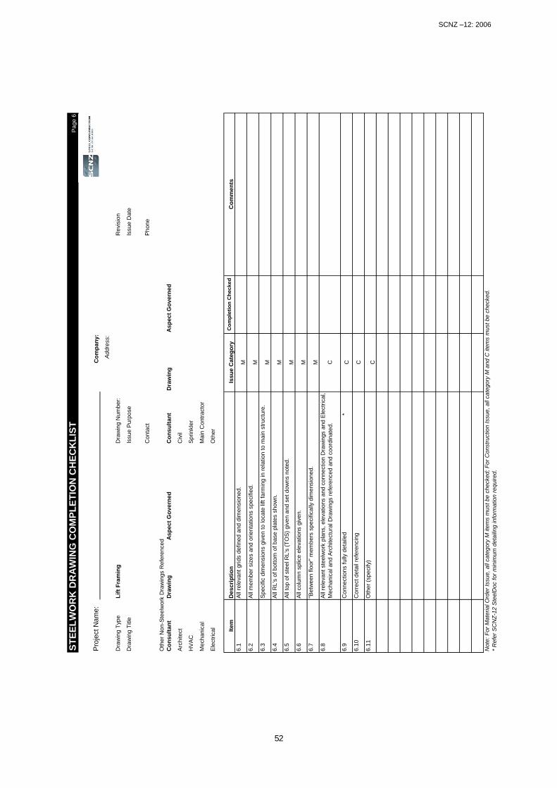
SCNZ –12: 2006
52
ST
EE
LW
OR
K D
RA
WIN
G C
OM
PL
ET
ION
CH
EC
KL
IST
Pa
ge
6
Pro
ject
Nam
e:
Co
mp
an
y:
Ad
dre
ss:
Dra
win
g T
ype
Lif
t F
ram
ing
Dra
win
g N
um
ber:
Re
vis
ion
Dra
win
g T
itle
Issue P
urp
ose
Issu
e D
ate
Con
tact
Phon
e
Oth
er
Non-S
teelw
ork
Dra
win
gs R
efe
rence
d
Co
nsu
ltan
tD
raw
ing
As
pect
Go
ve
rne
dC
on
su
ltan
tD
raw
ing
As
pe
ct
Go
ve
rne
d
Arc
hitect
Civ
il
HV
AC
Sprinkle
r
Mechanic
al
Main
Contr
acto
r
Ele
ctr
ical
Oth
er
Item
Issu
e C
ate
go
ry
6.1
M
6.2
M
6.3
M
6.4
M
6.5
M
6.6
M
6.7
M
6.8
C
6.9
C
6.1
0C
6.1
1C
Note
: F
or
Mate
rial O
rder
Issue, all
cate
gory
M ite
ms m
ust be c
hecke
d;
For
Constr
uctio
n Issue,
all
cate
gory
M a
nd
C ite
ms m
ust
be
ch
ecke
d.
* R
efe
r S
CN
Z-1
2 S
teelD
oc for
min
imum
deta
iling in
form
ation r
equired.
Oth
er
(specify)
Corr
ect deta
il re
fere
ncin
g
Connections f
ully
deta
iled
*
Descri
pti
on
Co
mp
leti
on
Ch
ec
ke
dC
om
men
ts
All
rele
vant grids d
efin
ed
and d
ime
nsio
ned.
All
mem
ber
siz
es a
nd
orienta
tio
ns s
pecifie
d.
Specific
dim
ensio
ns g
iven t
o loca
te lift
farm
ing in r
ela
tio
n to m
ain
str
uctu
re.
All
RL's
of
bottom
of
base p
late
s s
how
n.
All
top
of
ste
el R
L's
(T
OS
) giv
en a
nd s
et dow
ns n
ote
d.
All
colu
mn
splic
e e
levatio
ns g
ive
n.
"Betw
een
flo
or"
mem
bers
sp
ecific
ally
dim
ensio
ne
d.
All
rele
vant ste
elw
ork
pla
ns, ele
vations a
nd
connection D
raw
ings a
nd E
lectr
ica
l,
Mechanic
al and A
rchite
ctu
ral D
raw
ings r
efe
renced a
nd
coord
inate
d.

SCNZ –12: 2006
53
ST
EE
LW
OR
K D
RA
WIN
G C
OM
PL
ET
ION
CH
EC
KL
IST
Page 7
Pro
ject
Na
me
:C
om
pan
y:
Addre
ss:
Dra
win
g T
ype
Walk
ways a
nd
Access L
ad
ders
Dra
win
g N
um
ber:
Revis
ion
Dra
win
g T
itle
Issue P
urp
ose
Issue D
ate
Conta
ct
Phone
Oth
er
Non-S
teelw
ork
Dra
win
gs R
efe
renced
Consultant
Dra
win
gA
spect G
overn
ed
Consultant
Dra
win
gA
spect G
overn
ed
Arc
hitect
Civ
il
HV
AC
Sprinkle
r
Mechanic
al
Main
Contr
acto
r
Ele
ctr
ical
Oth
er
Item
Issu
e C
ate
go
ry
7.1
M
7.2
M
7.3
M
7.4
M
7.5
M
7.6
M
7.7
M
7.8
M
7.9
M
7.1
0
M
7.1
1C
7.1
2C
7.1
3C
Note
: F
or
Mate
rial O
rder
Issue, all
cate
gory
M ite
ms m
ust be c
hecked; F
or
Constr
uction Issue, all
cate
gory
M a
nd C
ite
ms m
ust be c
hecked.
* R
efe
r S
CN
Z-1
2 S
teelD
oc for
min
imum
deta
iling info
rmation r
equired.
Oth
er
(specify)
Descri
pti
on
Co
mp
leti
on
Ch
ec
ke
dC
om
men
ts
All
rele
vant grids d
efined a
nd d
imensio
ned.
All
mem
ber
siz
es a
nd o
rienta
tions s
pecifie
d.
Specific
dim
ensio
nin
g g
iven to locate
all
fram
ing in r
ela
tion to the m
ain
str
uctu
re.
All
RL's
of
bottom
of
base p
late
s s
how
n.
All
top o
f ste
el R
L's
(T
OS
) giv
en a
nd s
et dow
ns n
ote
d.
Connections f
ully
deta
iled *
All
mem
ber
splic
es locate
d.
"Betw
een f
loor"
mem
bers
specific
ally
dim
ensio
ned.
Hand a
nd g
uard
-rails
specifie
d a
nd s
et out dim
ensio
ns g
iven.
Foot tr
ead p
late
, fo
ot m
esh, la
dder
rungs a
nd f
ixin
gs s
pecifie
d a
nd s
et out.
All
rele
vant ste
elw
ork
pla
ns, ele
vations a
nd c
onnection D
raw
ings a
nd E
lectr
ical,
HV
AC
, S
prinkle
r and A
rchitectu
ral D
raw
ings r
efe
renced a
nd c
o-o
rdin
ate
d.
Corr
ect deta
il re
fere
ncin
g

SCNZ –12: 2006
54
ST
EE
LW
OR
K D
RA
WIN
G C
OM
PL
ET
ION
CH
EC
KL
IST
Page 8
Pro
ject
Nam
e:
Co
mp
an
y:
Addre
ss:
Dra
win
g T
ype
Ov
erh
ead
Cra
ne R
un
way G
ird
ers
Dra
win
g N
um
ber:
Revis
ion
Dra
win
g T
itle
Issue P
urp
ose
Issue D
ate
Issuin
g C
om
pany
Conta
ct
Phone
Oth
er
Non-S
teelw
ork
Dra
win
gs R
efe
renced
Co
nsu
ltan
tD
raw
ing
Asp
ect
Go
vern
ed
Co
nsu
ltan
tD
raw
ing
Asp
ect
Go
vern
ed
Arc
hitect
Civ
il
HV
AC
Sprinkle
r
Mechanic
al
Main
Contr
acto
r
Ele
ctr
ical
Oth
er
Item
Issu
e C
ate
go
ry
8.1
M
8.2
M
8.3
M
8.4
M
8.5
M
8.6
M
8.7
C
8.8
C
8.9
C
8.1
0M
8.1
1M
8.1
2C
8.1
3C
8.1
4C
8.1
5C
8.1
6C
Note
: F
or
Mate
rial O
rder
Issue, all
cate
gory
M ite
ms m
ust be c
hecked; F
or
Constr
uction Issue, all
cate
gory
M a
nd C
ite
ms m
ust be c
hecked.
* R
efe
r S
CN
Z-1
2 S
teelD
oc for
min
imum
deta
iling info
rmation r
equired.
Oth
er
(specify)
Connections f
ully
deta
iled *
The d
esig
n s
atisfies c
rane s
upplie
r re
quirem
ents
for
serv
iceabili
ty a
nd s
trength
.
All
rele
vant ste
elw
ork
pla
ns, ele
vations a
nd c
onnection D
raw
ings a
nd E
lectr
ical,
HV
AC
, S
prinkle
r and A
rchitectu
ral D
raw
ings r
efe
renced a
nd c
o-o
rdin
ate
d.
Pre
-cam
bers
specifie
d.
Specia
l le
velli
ng tole
rances s
pecifie
d.
Cra
ne r
ail
and c
rane r
ail
attachm
ent syste
ms to g
irders
adequate
ly s
pecifie
d.
End b
uff
ers
specifie
d.
All
rele
vant grids d
efined a
nd d
imensio
ned.
All
mem
ber
siz
es a
nd o
rienta
tions s
pecifie
d.
All
RL's
of
bottom
of
base p
late
s s
how
n.
All
top o
f ste
el R
L's
(T
OS
) giv
en.
Mem
bers
specific
ally
dim
ensio
ned.
Descri
pti
on
Co
mp
leti
on
Ch
ec
ke
dC
om
men
ts
Any
foot tr
ead p
late
, fo
ot m
esh a
nd f
ixin
gs s
pecifie
d a
nd s
et out.
Corr
ect deta
il re
fere
ncin
g
Girder
splic
es locate
d

SCNZ –12: 2006
55
ST
EE
LW
OR
K D
RA
WIN
G C
OM
PL
ET
ION
CH
EC
KL
IST
Page 9
Pro
ject
Nam
e:
Co
mp
an
y:
Addre
ss:
Dra
win
g T
ype
HV
AC
/ S
pri
nkle
r / E
lectr
ical S
up
po
rts
Dra
win
g N
um
ber:
Revis
ion
Dra
win
g T
itle
Issue P
urp
ose
Issue D
ate
Conta
ct
Phone
Oth
er
Non-S
teelw
ork
Dra
win
gs R
efe
renced
Co
nsu
ltan
tD
raw
ing
Asp
ect
Go
vern
ed
Co
nsu
ltan
tD
raw
ing
Asp
ect
Go
vern
ed
Arc
hitect
Civ
il
HV
AC
Sprinkle
r
Mechanic
al
Main
Contr
acto
r
Ele
ctr
ical
Oth
er
Item
Issu
e C
ate
go
ry
9.1
M
9.2
M
9.3
M
9.4
M
9.5
C
9.6
C
9.7
C
9.8
C
* R
efe
r S
CN
Z-1
2 S
teelD
oc for
min
imum
deta
iling info
rmation r
equired.
Oth
er
(specify)
Descri
pti
on
Co
mp
leti
on
Ch
ec
ke
dC
om
men
ts
All
rele
vant grids d
efined a
nd d
imensio
ned.
All
mem
ber
siz
es a
nd o
rienta
tions s
pecifie
d.
All
top o
f ste
el R
L's
(T
OS
) giv
en a
nd s
et dow
ns n
ote
d.
All
rele
vant ste
elw
ork
pla
ns, ele
vations a
nd c
onnection D
raw
ings a
nd E
lectr
ical,
HV
AC
, S
prinkle
r and A
rchitectu
ral D
raw
ings r
efe
renced a
nd c
o-o
rdin
ate
d.
Corr
ect deta
il re
fere
nces
Connections f
ully
specifie
d *
Specific
dim
ensio
nin
g g
iven to locate
all
the f
ram
ing in r
ela
tion to the m
ain
str
uctu
re.

SCNZ –12: 2006
56
ST
EE
LW
OR
K D
RA
WIN
G C
OM
PL
ET
ION
CH
EC
KL
IST
Pa
ge
10
Pro
ject
Na
me
:C
om
pa
ny:
Ad
dre
ss:
Dra
win
g T
yp
eC
lad
din
g S
ys
tem
sD
raw
ing N
um
ber:
Re
vis
ion
Dra
win
g T
itle
Issu
e P
urp
ose
Issu
e D
ate
Co
nta
ct
Ph
on
e
Oth
er
No
n-S
teelw
ork
Dra
win
gs R
efe
ren
ce
d
Co
ns
ult
an
tD
raw
ing
As
pe
ct
Go
ve
rne
dC
on
su
lta
nt
Dra
win
gA
sp
ec
t G
ov
ern
ed
Arc
hite
ct
Civ
il
HV
AC
Sp
rinkle
r
Mech
an
ica
lM
ain
Con
tra
cto
r
Ele
ctr
ica
lO
ther
Ite
mIs
su
e C
ate
go
ry
10.1
M
10.2
M
10.3
M
10.4
M
10.5
M
10.6
C
10.7
C
10.8
C
10.9
C
No
te:
Fo
r M
ate
ria
l O
rder
Issu
e,
all
ca
teg
ory
M ite
ms m
ust
be
ch
ecke
d;
Fo
r C
onstr
uctio
n I
ssu
e,
all
ca
teg
ory
M a
nd
C ite
ms m
ust
be
ch
ecke
d.
* R
efe
r S
CN
Z-1
2 S
teelD
oc f
or
min
imum
de
taili
ng in
form
atio
n r
equ
ire
d.
Co
mp
leti
on
Ch
ec
ke
dC
om
me
nts
Co
rre
ct
de
tail
refe
ren
cin
g
*
De
scri
pti
on
Co
nne
ctio
ns f
ully
deta
iled
All
rele
va
nt
grid
s d
efin
ed
an
d d
ime
nsio
ne
d.
All
me
mb
er
siz
es a
nd
orie
nta
tio
ns s
pecifie
d.
Sp
ecific
dim
ensio
nin
g g
ive
n t
o lo
ca
te a
ny f
ram
ing f
or
cla
dd
ing p
an
els
in
re
latio
n
to the m
ain
str
uctu
re.
All
top
of
ste
el R
L's
(T
OS
) g
ive
n a
nd
se
t d
ow
ns n
ote
d.
"Be
twe
en
flo
or"
me
mb
ers
sp
ecific
ally
dim
ensio
ne
d.
Re
leva
nt
ste
elw
ork
pla
ns,
ele
va
tio
ns a
nd
co
nn
ectio
n D
raw
ings,
Arc
hite
ctu
ral
Dra
win
gs a
nd
an
y o
ther
pro
prieta
ry d
raw
ings r
efe
ren
ce
d a
nd
co
-ord
inate
d.
Oth
er
(sp
ecify)

SCNZ –12: 2006
57
13 SteelDoc Documentation Checklist Software
13.1 Introduction
STEELDOC is a Microsoft Windows based application developed with Microsoft Visual Basic 6.0 and Excel. The program has been developed to help streamline office quality control by quickly preparing checklists for each structural steelwork drawing in an easy to use format. In addition to assisting in the process of ensuring completeness of drawings, the program also helps facilitates the coordination of all of the contract documentation that relate to the steelwork component of the project. The program has been based around the commonly accepted practice of categorizing steelwork drawings in the following manner:
Primary Structure (Floor structure, bracing elements, wall and roof structural elements) 1. General notes and specifications 2. Plans 3. Elevations 4. Connections
Free On Board Items (canopies, stairs, lift assemblies, walkways, ladders, HVAC plant supports, gantry girders)
Provided the drawing set is prepared on this manner, a check list appropriate for each structural drawing will be prepared. The program will generate checklists for up to 100 drawings. The file should be run on an IBM PC or compatible using Microsoft Windows XP and Excel XP or later versions.
13.2 Installation
Create a folder on the local drive of the users computer (e.g. C:\STEELDOC) Copy “SteelDoc.xls” into the SteelDoc folder. The program cannot be run directly from the CD Rom.
13.3 Input and Output Procedures
The various pages of the program are accessed from a single menu, see figure 1. To make the program easy to navigate the inputting functions have been separated into initial setup information and the checklists. Each sheet of the program may be printed by clicking the print button on the spreadsheet tool bar.
13.3.1 Step 1: Initial Setup – Design Consultants Contact Details Selection
Select the intial setup box. A second box will appear to the right of the first. Click on the drop
down box button. The user will be given the choice of three page options. Select Contact Details
and then click the Go button, refer figure 1. The project details, including contact details can be inputted into the programme by clicking on the appropriate cell and typing in the required information. Data from other Excel spreadsheets
may also be input using the Copy and Paste Special functions or control q. When the Contact

SCNZ –12: 2006
58
SteelDoc 1.0
Initial Setup
Check Lists
Contact Details Go
Figure 1 Main menu - navigation features
List sheet is opened a pop up box will remind users of the correct paste procedure to avoid formatting problems.
Information in the sheet may be amended by clicking on the required cell and using standard Excel spreadsheet editing procedures
. The user may either clear data one row at a time by clicking on any cell in the required row and
selecting the Delete selected contact button or by using the Reset button to clear all the contact
information, see figure 2. A pop up box will appear following activation of the Reset button to allow users the chance to confirm their intention to delete all contact details.
Click to activate drop down box
Figure 2 Contact List Page
Navigation buttons
Delete all data
Delete single contact record
b

SCNZ –12: 2006
59
There is no requirement to save inputted data prior to exiting the page. To return to the main
menu click the Return to Menu button located at the bottom of the page, see figure 2.
Alternatively the Drawing List page can accessed by clicking the appropriate box at the bottom of the page, refer figure 2.
13.3.2 Step 2: Initial Setup – Contract Drawing List Selection
The contract drawing list page may be accessed either by activating the initial setup information button and selecting the drawing list option from the drop down box as per step 1 or from one of the other two initial setup information pages (Design Consultant’s Contact List and Design Consultants Task Checklist). The minimum information required for SteelDoc is the structural drawing list with drawings categorized as previously discussed in the introduction section. To allow relevant information from other documents to be easily found for coordination and checking purposes, it is recommended that the appropriate other referenced documents boxes be filled in, see figure 3 The project details will automatically appear on the page if the Design Consultant Contacts List sheet has been completed. The user may add the date by clicking on the appropriate cell and typing the required information.
Figure 3 Contact drawing list page Data entry can either be by clicking on the appropriate cell and typing the required information or by copying and pasting columns of data from other spreadsheets. If data is inputted from other spreadsheets it should be done so as single columns rather than as blocks. To avoid formatting
problems, data should be pasted using either control q or the paste special function. The user must nominate for each drawing the appropriate drawing category. The drawing category box is activated by clicking on the right hand side of the drawing category cell. To remove a single drawing entry, click on any cell on the line to be removed and select the
Delete selected drawing button located on the top left hand side of the screen. To clear all data
from the contract drawing list page, activate the Reset button also located on the top left hand side of the screen. To avoid erroneously deleting all the data, the program asks the user to confirm their intention to reset the page. To edit data, click on the required cell and retype the correct data. To close line gaps caused by
using the Delete selected line button or to rearrange the order of the drawing list, the copy and
Navigation buttons
Delete all data Save data
Delete single line of data

SCNZ –12: 2006
60
Figure 4 Consultant task checklist
control q or paste special functions can be used. If during the course of editing information the screen formatting is lost, it can be restored by using the reset function. The user should note that using this function will in addition to restoring lost formatting also remove all data from the page.
To save data, click on the Update button located top left side of the screen before exiting the screen.
The user can either return to the previous page by activating the Contact List button located at
the top right hand side of the sheet or move to the next initial setup page via the Task Checklist
button. A final option is to return to the main menu page via the Return to Menu button, see figure 3.
13.3.3 Step 3: Initial Setup – Design Consultant Task Checklist Selection
The Task Allocation page can be accessed from either the Menu page as per step 1 or the Drawing List page. The tasks listed itemize all the information required to be included in the structural steelwork design documentation. The majority of the information required will be provided by the Structural Engineer. In recognition of this fact, most of the tasks are allocated by default to the Structural
Engineer. To reset to this default position, click the Reset button located at the top and bottom of the page, refer figure 4. However, there are tasks that will be the responsibility of other members of the design team ie specifying coating systems or coordinating drawings. To ensure tasks do not fall through the cracks so to speak, the Principal Consultant can use this page as a tool to ensure that all the tasks have been allocated to the design team and that everyone is aware of their responsibilities in this regard.
To change the task allocation to another party, click the tab on the appropriate responsibility column cell, this will activate a drop down box, see figure 4. Click on the required party to change to the task allocation. The data will automatically be saved once the page is completed. To return to the main menu or the previous page, click on the appropriate navigation buttons located at the top and bottom right hand side of the page, refer figure 4.
Activated drop down box
Navigation buttons

SCNZ –12: 2006
61
SteelDoc 1.0
Initial Setup
Check Lists Plans Go
Figure 5 Checklist option selected from menu page
Figure 6 Completion checklist page - drawing title drop down box activated
13.3.4 Step 4: Check Lists Selection
The check list pages are accessed from the menu page, see figure 5. The program will generate a separate checklist for each drawing. The drawings are accessed by category type. Click the
check list button on the menu page to activate a second box. Once the drop down button has been clicked, a list of the drawing categories is displayed from which the user may chose. Select
the drawing category, in this instance Plans, see figure 5, followed by the Go button. Once in the Steelwork Drawing Completion Check List page, the required drawing is found by clicking on the drawing list. A drop down box listing all the drawings under the chosen drawing category will appear, see figure 6. The sheet will now display the relevant drawing information previously inputted in steps 1 and 2. Users will note for each task there is an issue category designated M or C which refers to Material Order and Connections. This is discussed in section 6.8
b
Click to activate drop box
Plan drawings listed

SCNZ –12: 2006
62
Figure 7 Completion checklist page - drawing type drop down box activated
To access drawings with a different drawing category, click on the drawing type drop down button, see figure 7. This will activate a drop down box with a selection of categories the user may choose from. To pick the required drawing within the category, repeat the procedure discussed in the previous paragraph. The input options for the checklist pages are as follows:
Once a task is completed the appropriate box may be clicked to record a tick, see figure 7
Comments may also be recorded for each task in the column located on the right hand side of the sheet. To input data click on the appropriate cell and begin typing
Comments may also be added to the other non structural drawings referenced portion of the page. For example an architectural drawing referenced may contain set out information, the Aspect Governed column allows the user to record this was the reason for referencing this drawing. The intention is that this will make checking and coordinating the drawings easier in the future
To save the inputted information, the Save button located on the top right hand side of the page must be activated. To clear all the user inputted data for the drawing type on the screen (this may involve several
drawings), click the Reset button. Before the data is deleted the user will be asked to confirm this request. Activating the reset button will also remove all the drawing titles displayed in the drawing title box. The drawing titles can be reinstated using the following steps.
Exit the completion check list page via the Return to Menu button
Access the contract drawing list from the initial setup menu
Once in the contract drawing list page click the Update button
Return to the appropriate checklist page. The deleted drawing titles should now be displayed if the drawing title drop down box is activated.
If there is more than one drawing per drawing type and it is only required to delete checklist data for a single drawing, the user may undertake the following steps:
Exit the Completion Checklist page and return to the Contract Drawing List input screen via the initial setup menu
Click to activate drop box
Drawing categories
Click box to leave tick

SCNZ –12: 2006
63
Delete the appropriate drawing using the Delete selected drawing button
Click the update button
Retype the deleted drawing title data
Select the Update button
Return to the original checklist page
Activate the drawing title drop down box to select the required drawing title.
To save inputted or edited information, click the Save button located on the top right hand side of the page.
To return to the main menu, click the Return to Menu button located top hand corner of page, see figure 7.

SCNZ –12: 2006
64

SCNZ –12: 2006
65
14 Conclusion
The use of structural steelwork in construction in New Zealand is rapidly increasing. While the design and construction methods used is constantly changing the three fundamentals of good design documentation remain. They are clarity of presentation, lack of ambiguity and completeness in defining the Contract Works. The Principal’s Representative and the design consultants that prepare the Contract Documents that he or she issues on behalf of the Principal, have a pivotal role in facilitating the continuing development of a reliable and cost effective construction industry in New Zealand. SteelDoc: Code of Practice for Structural Steelwork Documentation aims to clarify the issues that should be addressed to ensure the success of steel construction projects in New Zealand.

SCNZ –12: 2006
66

SCNZ –12: 2006
67
15 References
Some steel construction reference material useful in improving one’s appreciation of the components of successful steel construction are as follows: Carter, C., “Economical Design of Steel Structures”, American Institute of Steel Construction. Clifton, G.C., “HERA Specification for the Fabrication, Erection and Surface Treatment of Structural Steelwork”, HERA Report R4-99:1998, New Zealand Heavy Engineering Research Association, Manukau City, 1998. “Code of Practice for Steel Buildings and Bridges”, American Institute of Steel Construction, Chicago, USA, 1992. “Conditions of Contract for Building and Civil Engineering Construction”, NZS 3910:1998, Standards New Zealand, Wellington, 1998. “Design Guidelines for Successful Steel Detailing”, National Institute of Steel Detailing, Inc., Oakland, USA, 1999. “Steel Structures Standard”, NZS 3404:1997, Standards New Zealand, 1997. “Structural Steelwork Connections Guide”, SCNZ-15:2006, Steel Construction New Zealand Inc., 2006 (Formerly HERA Report R4-100:1999, New Zealand Heavy Engineering Research Association, 1999.) Troupe, E.W.J., “Effective Contract and Shop Drawings”, Steel Construction, AISC, May 1999 “Working with Structural Steel in Schedule Driven Projects”, American Institute of Steel Construction, March 1996.