SCL/SCM series V.F.D. for TFI hoods
60
Installation and Operation Manual SCL/SCM Series
Transcript of SCL/SCM series V.F.D. for TFI hoods

Installation and Operation Manual
SCL/SCM Series


SM01M
Contents
1 GENERAL . . . . . . . . . . . . . . . . . . . . . . . . . . . . . . . . . . . . . . . . . . . . . . . 2
1 .1 ProductsCoverednThsManual . . . . . . . . . . . . . . . . . . . . . 2
1 .2 ProductChanges . . . . . . . . . . . . . . . . . . . . . . . . . . . . . . . . . 2
1 .3 Warranty . . . . . . . . . . . . . . . . . . . . . . . . . . . . . . . . . . . . . . . . 2
1 .4 Recevng . . . . . . . . . . . . . . . . . . . . . . . . . . . . . . . . . . . . . . . 2
1 .5 SafetyInformaton . . . . . . . . . . . . . . . . . . . . . . . . . . . . . . . . . 2
1 .6 CustomerModficaton . . . . . . . . . . . . . . . . . . . . . . . . . . . . . 4
2 SCL/SCMDIMENSIONS . . . . . . . . . . . . . . . . . . . . . . . . . . . . . . . . . . . . 5
3 SCL/SCMMODELDESIGNATIONCODE . . . . . . . . . . . . . . . . . . . . . . 7
4 SCL/SCMSPECIFICATIONS . . . . . . . . . . . . . . . . . . . . . . . . . . . . . . . . 7
5 SCL/SCMRATINGS . . . . . . . . . . . . . . . . . . . . . . . . . . . . . . . . . . . . . . . 8
6 INSTALLATION . . . . . . . . . . . . . . . . . . . . . . . . . . . . . . . . . . . . . . . . . . . 9
6 .1 InstallatonAfteraLongPerodofStorage . . . . . . . . . . . . . . 9
7 INPUTACPOWERREQUIREMENTS . . . . . . . . . . . . . . . . . . . . . . . . 10
7 .1 InputVoltageRatngs . . . . . . . . . . . . . . . . . . . . . . . . . . . . . 10
7 .2 InputFusngRequrements . . . . . . . . . . . . . . . . . . . . . . . . . 11
7 .3 InputWreSzeRequrements . . . . . . . . . . . . . . . . . . . . . . 12
7 .4 InstallatonAccordngtoEMCRequrements . . . . . . . . . . . 12
8 POWERWIRING . . . . . . . . . . . . . . . . . . . . . . . . . . . . . . . . . . . . . . . . 13
8 .1 InputandOutputWrng . . . . . . . . . . . . . . . . . . . . . . . . . . . 13
9 SCL/SCMPOWERWIRINGDIAGRAM . . . . . . . . . . . . . . . . . . . . . . . 14
10 CONTROLWIRING . . . . . . . . . . . . . . . . . . . . . . . . . . . . . . . . . . . . . . 15
10 .1 ControlWrngvs .PowerWrng . . . . . . . . . . . . . . . . . . . . . 15
10 .2 TB-2:CrcutCommon . . . . . . . . . . . . . . . . . . . . . . . . . . . . . 15

SM01M
10 .3 SurgeSuppressononRelays . . . . . . . . . . . . . . . . . . . . . . . 15
10 .4 Start/StopControl . . . . . . . . . . . . . . . . . . . . . . . . . . . . . . . . 15
10 .5 SpeedReferenceSgnals . . . . . . . . . . . . . . . . . . . . . . . . . . 15
10 .6 SpeedReferenceSelecton . . . . . . . . . . . . . . . . . . . . . . . . 16
10 .7 DrveStatusDgtalOutputs . . . . . . . . . . . . . . . . . . . . . . . . 17
11 SCL/SCMCONTROLWIRINGDIAGRAMS . . . . . . . . . . . . . . . . . . . . 18
11 .1 SCL/SCMTermnalStrp . . . . . . . . . . . . . . . . . . . . . . . . . . . 18
11 .2 Two-WreStart/StopControl . . . . . . . . . . . . . . . . . . . . . . . . 19
11 .3 Three-WreStart/StopControl . . . . . . . . . . . . . . . . . . . . . . . 20
11 .4 PresetSpeeds&SpeedPot(2-WreStart/StopControl) . . 21
12 INITIALPOWERUPANDMOTORROTATION . . . . . . . . . . . . . . . . 22
13 PROGRAMMINGTHESCL/SCMDRIVE . . . . . . . . . . . . . . . . . . . . . . 24
13 .1 SettngValuesnTenthsofUntsAbove100 . . . . . . . . . . . 25
13 .2 ElectroncProgrammngModule(EPM) . . . . . . . . . . . . . . . 26
14 PARAMETERMENU . . . . . . . . . . . . . . . . . . . . . . . . . . . . . . . . . . . . . 28
15 DESCRIPTIONOFPARAMETERS . . . . . . . . . . . . . . . . . . . . . . . . . . 31
16 TROUBLESHOOTING . . . . . . . . . . . . . . . . . . . . . . . . . . . . . . . . . . . . 46
17 SCL/SCMDISPLAYMESSAGES . . . . . . . . . . . . . . . . . . . . . . . . . . . . 48
17 .1 SpeedDsplay . . . . . . . . . . . . . . . . . . . . . . . . . . . . . . . . . . . 48
17 .2 ChangngtheSpeedReferenceSource . . . . . . . . . . . . . . . 48
17 .3 StatusandWarnngMessages . . . . . . . . . . . . . . . . . . . . . . 49

1 SM01M
THE SCL/SCM SUB-MICRO DRIVE
ElectronicProgrammingModuleEPM
ProgrammingButtons
Output Motor Terminals
Control Terminal Strip
3-Digit LED Display
DC Bus TerminalsInput Power Terminals(3 left terminals) (2 right terminals)
Safety InformationAllsafetynformatongvenntheseOperatngInstructonshasthesamelayout:
Signal Word!(characterzesthesevertyofthedanger)
Note(descrbesthedangerandnformsonhowtoproceed)
Icon Signal Words
Warnngofhazardouselectrcalvoltage
DANGER! Warnsofimpending danger .Consequencesfdsregarded:Deathorseverenjures .
Warnngofageneraldanger
WARNING! Warnsofpotential, very hazardous situations .Consequencesfdsregarded:Deathorseverenjures .
Warnngofdamagetoequpment
STOP! Warnsofpotential damage to material and equipment .Consequencesfdsregarded:Damagetothecontroller/drveortsenvronment .
Informaton Note Desgnatesageneral,usefulnote .Ifyouobservet,handlngthecontroller/drvesystemsmadeeaser .

SM01M 2
1 GENERAL1.1 Products Covered in This Manual
ThsmanualcoverstheACTechSCLandSCMSeresVarableFrequencyDrves .
1.2 Product Changes
ACTechnologyCorporatonreservestherghttodscontnueormakemodficatonstothedesgnoftsproductswthoutprornotce,andholdsnooblgatontomakemodficatonstoproductssoldprevously .ACTechnologyCorporatonalsoholdsnolabltyforlossesofanykndwhchmayresultfromthsacton .Instructonmanualswththemostup-to-datenformatonareavalablefordownloadfromtheACTechwebste(www .actech .com) .
1.3 Warranty
ACTechnologyCorporatonwarrantstheSCL/SCMSeresACmotorcontroltobefreeofdefectsnmateralandworkmanshpforaperodof24monthsfromthedateofshpmentfromACTech'sfactory .If,undernormaluse,anSCL/SCMmotorcontrolbecomesdefectvewthnthestatedwarrantytmeperod,contactACTechnology'sServceDepartmentfornstructonsonobtanngawarrantyreplacementunt .ACTechnologyCorporatonreservestherghttomakethefinaldetermnatonastothevaldtyofawarrantyclam,andsoleoblgatonstoreparorreplaceonlycomponentswhchhavebeenrendereddefectveduetofaultymateralorworkmanshp .Nowarrantyclamwllbeacceptedforcomponentswhchhavebeendamagedduetomshandlng,mpropernstallaton,unauthorzedreparand/oralteratonoftheproduct,operatonnexcessofdesgnspecficatonsorothermsuse,ormpropermantenance .ACTechnologyCorporatonmakesnowarrantythattsproductsarecompatblewthanyotherequpment,ortoanyspecficapplcaton,towhchtheymaybeappledandshallnotbeheldlableforanyotherconsequentaldamageornjuryarsngfromtheuseoftsproducts .
This warranty is in lieu of all other warranties, expressed or implied. No other person, firm or corporation is authorized to assume, for AC Technology Corporation, any other liability in connection with the demonstration or sale of its products.
1.4 Receiving
Inspect all cartons for damage whch may have occurred durng shppng . Carefullyunpackequpmentandnspectthoroughlyfordamageorshortage .Reportanydamagetocarrerand/orshortagestosuppler .Allmajorcomponentsandconnectonsshouldbeexamnedfordamageandtghtness,wthspecalattentongventoPCboards,plugs,knobsandswtches .
1.5 Safety Information
SomepartsofACTechcontrollerscanbeelectrcallylveandsomesurfacescanbehot .Non-authorzedremovaloftherequredcover,napproprateuse,andncorrectnstallatonoroperatoncreatestherskofseverenjurytopersonnelordamagetoequpment .Alloperatonsconcernngtransport,nstallaton,andcommssonngaswellasmantenancemustbecarredoutbyqualfied,sklledpersonnelfamlarwththenstallaton,assembly,commssonng,andoperatonofvarablefrequencydrvesandtheapplcatonnwhchthedrvesused .

3 SM01M
INSTALLATION
Ensure proper handlng and avod excessve mechancal stress . Do not bend anycomponents and do not change any nsulaton dstances durng transport, handlng,nstallatonormantenance .
Donottouchanyelectronccomponentsorcontacts .Thsdrvecontanselectrostatcallysenstvecomponents,whchcaneaslybedamagedby nappropratehandlng .Statccontrolprecautonsmustbeadheredtodurngnstallaton,testng,servcngandreparngofthsdrveandassocatedoptons .Componentdamagemayresultfproperproceduresarenotfollowed .
ThsdrvehasbeentestedbyUnderwrtersLaboratory(UL)andsanapprovedcomponentncomplancewthUL508CSafetyStandard .
Warnings!
•SutableforuseonacrcutasdescrbednSecton7 .0ofthsmanual .
•Usemnmum75°Ccopperwreonly .
•ShallbenstallednaPollutonDegree2macro-envronment .
Thsdrvemustbenstalledandconfigurednaccordancewthbothnatonalandnternatonalstandards .LocalcodesandregulatonstakeprecedenceoverrecommendatonsprovdednthsandotherACTechdocumentaton .
Thedrvesconsderedacomponentforntegratonntoamachneorprocess .ItsnetheramachnenoradevcereadyforusenaccordancewthEuropeandrectves(referencemachnerydrectveandelectromagnetccompatbltydrectve) .Itstheresponsbltyoftheendusertoensurethatthemachnemeetstheapplcablestandards .
ELECTRICALCONNECTION
Whenworkngon lvedrvecontrollers,applcablenatonalsafety regulatonsmustbeobserved . The electrcal nstallaton must be carred out accordng to the approprateregulatons (e .g . cable cross-sectons, fuses, protectveearth [PE] connecton) .Whlethsdocumentdoesmakerecommendatonsnregardstothesetems,natonalandlocalcodesmustbeadheredto .
The documentaton contans nformaton about nstallaton n complance wth EMC(sheldng,groundng,filtersandcables) .Thesenotesmustalsobeobserved forCE-marked controllers . The manufacturer of the system or machne s responsble forcomplancewththerequredlmtvaluesdemandedbyEMClegslaton .
APPLICATION
Thedrvemustnotbeusedasasafetydevce formachneswhere there sa rskofpersonalnjuryormateraldamage .EmergencyStops,over-speedprotecton,acceleratonanddeceleratonlmts,etcmustbemadebyotherdevcestoensureoperatonunderallcondtons .

SM01M 4
Thedrvedoesfeaturemanyprotectondevceswhchareamedatprotectngthedrveandthedrvenequpmentbygeneratngafaultandshuttngthedrveandmotordownbyremovngpower .Manspowervarancescanalsoresultnshutdownofthedrve .Whenthefaultcondtondsappearsorscleared,thedrvecanbeconfiguredtoautomatcallyrestart,tstheresponsbltyoftheuser,OEMand/orntegratortoensurethatthedrvesconfiguredforsafeoperaton .
1.6 Customer Modification
AC Technology Corporaton, ts sales representatves and dstrbutors, welcome theopportuntytoassstourcustomersnapplyngourproducts .Manycustomoptonsareavalabletoadnthsfuncton .ACTechnologyCorporatoncannotassumeresponsbltyforanymodficatonsnotauthorzedbytsengneerngdepartment .

5 SM01M
2 SCL/SCM DIMENSIONS
DmensonsfortheSCL/SCMmodelsrated0 .33-1 .5Hp(0 .25-1 .1kW) .
If R<6 .30"(160) S=0 .19"(5) T=0 .38"(10) U=0 .18"(5) V=0 .66"(17)
If R=6 .30"(160) S=0 .28"(7) T=0 .50"(13) U=0 .24"(6) V=0 .90"(23)
MountngTabDetal
D
W
P SDa .Slot
R
TU
V
H
HP kW INPUT VOLTAGE
INPUT PHASE
SCM MODEL
SCL MODEL H W D P R
0.33 0.25120 1 SM004S N/A 5.75 (146) 2.88 (74) 3.26 (83) 0.28 (7) 4.37 (111)
208 / 240 1 SM204S SL204S 5.75 (146) 2.88 (74) 3.26 (83) 0.28 (7) 4.37 (111)
0.5 0.37
120 1 SM005S N/A 5.75 (146) 2.88 (74) 3.26 (83) 0.28 (7) 4.37 (111)
208 / 240 1 SM205S SL205S 5.75 (146) 2.88 (74) 3.26 (83) 0.28 (7) 4.37 (111)
208 / 240 3 SM205 N/A 5.75 (146) 2.88 (74) 3.26 (83) 0.28 (7) 4.37 (111)
400 / 480 3 SM405 N/A 5.75 (146) 2.88 (74) 3.94 (100) 0.80 (20) 4.37 (111)
0.75 0.55 208 / 240 1 SM208S SL208S 5.75 (146) 2.88 (74) 3.63 (92) 0.63 (16) 4.37 (111)
1 0.75
120 1 SM010S N/A 5.75 (146) 3.76 (95) 4.88 (124) 1.50 (38) 4.37 (111)
208 / 240 1 SM210S SL210S 5.75 (146) 2.88 (74) 3.63 (92) 0.63 (16) 4.37 (111)
208 / 240 3 SM210 N/A 5.75 (146) 2.88 (74) 3.63 (92) 0.63 (16) 4.37 (111)
480 / 590 3 SM410 N/A 5.75 (146) 2.88 (74) 4.74 (120) 1.60 (41) 4.37 (111)
1.5 1.1
120 1 SM015S N/A 5.75 (146) 3.76 (96) 4.88 (124) 1.50 (38) 4.37 (111)
208 / 240 1 SM215S SL215S 5.75 (146) 3.76 (96) 4.88 (124) 1.50 (38) 4.37 (111)
208 / 240 3 SM215 N/A 5.75 (146) 2.88 (73) 5.56 (141) 2.56 (65) 4.37 (111)
400 / 480 3 SM415 N/A 5.75 (146) 2.88 (73) 5.74 (146) 2.56 (65) 4.37 (111)
Dmensonsshownarennchesand(mm) .

SM01M 6
DmensonsfortheSCL/SCMmodelsrated2-15Hp(1 .5-11kW) .
If R<6 .30"(160) S=0 .19"(5) T=0 .38"(10) U=0 .18"(5) V=0 .66"(17)
If R=6 .30"(160) S=0 .28"(7) T=0 .50"(13) U=0 .24"(6) V=0 .90"(23)
MountngTabDetal
D
W
P SDa .Slot
R
TU
V
H
HP kW INPUT VOLTAGE
INPUT PHASE
SCM MODEL
SCL MODEL H W D P R
2 1.5
208 / 240 1 SM220S SL220S 5.75 (146) 3.76 (95) 4.88 (124) 1.50 (38) 4.37 (111)
208 / 240 3 SM220 N/A 5.75 (146) 2.88 (74) 5.56 (141) 2.56 (65) 4.37 (111)
400 / 480 3 SM420 N/A 5.75 (146) 2.88 (74) 5.74 (146) 2.56 (65) 4.37 (111)
3 2.2
208 / 240 1 SM230S SL230S 5.75 (146) 3.76 (95) 5.53 (140) 2.18 (55) 4.37 (111)
208 / 240 3 SM230 N/A 5.75 (146) 3.76 (95) 5.53 (140) 2.18 (55) 4.37 (111)
400 / 480 3 SM430 N/A 5.75 (146) 3.76 (95) 5.24 (133) 1.90 (48) 4.37 (111)
5 4.0208 / 240 3 SM250 N/A 5.75 (146) 3.76 (95) 6.74 (171) 3.40 (160) 3.25 (83)
400 / 480 3 SM450 N/A 5.75 (146) 3.76 (95) 6.74 (171) 3.40 (160) 3.25 (83)
7.5 5.5208 / 240 3 SM275 N/A 7.75 (197) 5.02 (128) 7.18 (182) 3.40 (86) 4.81 (122)
400 / 480 3 SM475 N/A 5.75 (146) 3.76 (95) 6.74 (171) 3.40 (160) 3.25 (83)
10 7.5208 / 240 3 SM2100 N/A 7.75 (197) 5.02 (128) 7.18 (182) 3.40 (86) 4.81 (122)
400 / 480 3 SM4100 N/A 7.75 (197) 5.02 (128) 7.18 (182) 3.40 (86) 4.81 (122)
15 11208 / 240 3 SM2150 N/A 9.75 (248) 6.68 (170) 8.00 (203) 3.40 (86) 6.30 (160)
400 / 480 3 SM4150 N/A 7.75 (197) 5.02 (128) 7.18 (182) 3.60 (91) 4.81 (122)
Dmensonsshownarennchesand(mm)

7 SM01M
3 SCL/SCM MODEL DESIGNATION CODE
TheSCL/SCMmodelnumbergvesafulldescrptonofthebascdrveunt .
EXAMPLE: SL210S=SCLSeres,208/240Vac,1HP,snglephasenput
SL 2 10 S Series:
SL = SCL Series Variable Speed AC Motor Drive with integral line filterSM = SCM Series Variable Speed AC Motor Drive
Input Voltage:0 = 120 Vac (For 110, 115, and 120 Vac; 50 or 60 Hz)2 = 208/240 Vac (For 208, 220, 230, and 240 Vac; 50 or 60 Hz)4 = 400/480 Vac (For 380, 415, 460, and 480 Vac; 50 or 60 Hz)
Rating:4 = 0.33 Hp (0.25 15 = 1.5 Hp (1.1 kW) 75 = 7.5 Hp (5.5 kW)5 = 0.50 Hp (0.37 20 = 2 Hp (1.5 kW) 100 = 10 Hp (7.5 kW)8 = 0.75 Hp (0.55 30 = 3 Hp (2.2 kW) 150 = 15 Hp (11 kW)
10 = 1 Hp (0.75 kW) 50 = 5 Hp (4.0 kW) Input Phase:
S = Single phase input only.No character indicates three phase input only
4 SCL/SCM SPECIFICATIONS
Conformity CE Low Voltage Directive (73/23/EEC)Approvals UL 508C Underwriters Laboratories - Power Conversion EquipmentStorage Temperature -20° to 70° CAmbient Operating Temperature 0° to 40° C (derate 2.5% per °C above 40°)Ambient Humidity < 95% (non-condensing)Altitude 3300 ft (1000 m) above sea level (derate 5% per additional 3300 ft)Input Line Voltages 120, 208/240, 400/480 VacInput Voltage Tolerance +10%, -15%Input Frequency Tolerance 48 to 62 HzOutput Wave Form Sine Coded PWMOutput Frequency 0 - 240 HzCarrier Frequency 4 kHz to 10 kHz (10 kHz requires derating; see parameter P02)Service Factor 1.00 (up to 8 kHz carrier; derate for 10 kHz; see parameter P02)Efficiency Up to 98%Power Factor (displacement) 0.96 or betterOverload Current Capacity 150% for 60 seconds, 180% for 30 secondsSpeed Reference Follower 0-10 VDC, 4-20 mA
Digital Outputs(1) Normally open relay; contacts rated 3 amps at 250 Vac(1) Digital output (current-sourcing); rated 50 mA at 12 VDC
Earth Leakage Current (EN 50178) SCL: > 3.5 mA to PE SCM: < 3.5 mA to PE
SM01M 8
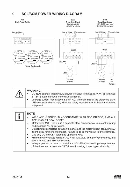
5 SCL/SCM RATINGS
SCM SCL FOR INPUT OUTPUT HEAT
MODEL MODEL MOTORS (50-60Hz) (3phase) LOSS1
NUMBER NUMBER RATED INPUT CURRENT POWER CURRENT (WATTS)
HP kW PHASE (AMPS) (kVA) (AMPS)
120 Vac INPUT MODELS 120 Vac 0 - 230 Vac
SM004S N/A 0 .33 0 .25 1 6 .8 0 .8 1 .7 29
SM005S N/A 0 .50 0 .37 1 9 .2 1 .1 2 .4 33
SM010S N/A 1 0 .75 1 16 .6 2 .0 4 .2 57
SM015S N/A 1 .5 1 .1 1 24 2 .9 6 .0 86
208 / 240 Vac INPUT MODELS 208 / 240 Vac 0 - 208 / 230 Vac
SM204S SL204S 0 .33 0 .25 1 3 .9/3 .4 0 .8 1 .9/1 .7 23
SM205S SL205S 0 .50 0 .37 1 5 .8/5 .0 1 .2 2 .8/2 .4 31
SM205 N/A 0 .50 0 .37 3 3 .1/2 .7 1 .1 2 .8/2 .4 31
SM208S SL208S 0 .75 0 .55 1 6 .9/6 .0 1 .4 3 .7/3 .2 34
SM210S SL210S 1 0 .75 1 10 .6/9 .2 2 .2 4 .8/4 .2 47
SM210 N/A 1 0 .75 3 5 .8/5 .1 2 .1 4 .8/4 .2 47
SM215S SL215S 1 .5 1 .1 1 13 .9/12 .0 2 .9 6 .9/6 .0 68
SM215 N/A 1 .5 1 .1 3 8 .0/6 .9 2 .9 6 .9/6 .0 68
SM220S SL220S 2 1 .5 1 18 .4/16 .0 3 .1 8 .1/7 .0 71
SM220 N/A 2 1 .5 3 9 .1/7 .9 3 .3 8 .1/7 .0 71
SM230S SL230S 3 2 .2 1 24/21 4 .1 11 .0/9 .6 108
SM230 N/A 3 2 .2 3 12 .4/10 .8 4 .5 11 .0/9 .6 108
SM250 N/A 5 4 .0 3 19 .6/17 .1 7 .1 17 .5/15 .2 173
SM275 N/A 7 .5 5 .5 3 28/25 10 .3 25/22 286
SM2100 N/A 10 7 .5 3 34/32 13 .1 30/28 379
SM2150 N/A 15 11 3 54/48 20 .0 48/42 476
400 / 480 Vac INPUT MODELS 400 / 480 Vac 0 - 400 / 460 Vac
SM405 N/A 0 .50 0 .37 3 1 .6/1 .4 1 .1 1 .3/1 .1 31
SM410 N/A 1 0 .75 3 3 .0/2 .5 2 .1 2 .5/2 .1 47
SM415 N/A 1 .5 1 .1 3 4 .3/3 .6 3 .0 3 .6/3 .0 58
SM420 N/A 2 1 .5 3 4 .8/4 .0 3 .3 4 .1/3 .4 63
SM430 N/A 3 2 .2 3 6 .4/5 .4 4 .5 5 .8/4 .8 92
SM450 N/A 5 4 .0 3 10 .6/8 .8 7 .1 9 .4/7 .8 155
SM475 N/A 7 .5 5 .5 3 14 .2/12 .4 10 .3 12 .6/11 .0 254
SM4100 N/A 10 7 .5 3 18 .1/15 .8 13 .1 16 .1/14 .0 310
SM4150 N/A 15 11 3 27/24 20 .0 24/21 390
1Valuesshownfor6kHzcarrerfrequencyatfullspeedandfullload .

9 SM01M
6 INSTALLATION
NOTESCL/SCM Seres drves are ntended for ncluson wthn other equpment, byprofessonalelectrcalnstallersaccordngtoEN61000-3-2 .Theyarenotntendedforstand-aloneoperaton .
WARNING!Drvesmustnotbenstalledwheresubjectedtoadverseenvronmentalcondtonssuch as: combustble, oly, or hazardous vapors or dust; excessve mosture ordrt;vbraton;excessveambent temperatures .ConsultACTechnology formorenformatononthesutabltyofadrvetoapartcularenvronment .
SCL/SCMmodelsaresutableforULPollutonDegree2envronmentonly,andMUSTbenstallednanelectrcalenclosurethatwllprovdecompletemechancalprotectonandwllmantanthenternaltemperaturewthnthedrve’sambentoperatngtemperatureratng .AlldrvemodelsMUSTbemountednavertcalpostonforproperheatsnkcoolng .
Mantanamnmumspacngaroundthedrveofatleast1nch(25mm)oneachsdeand2nches(50mm)onthetopandbottomforuntsupto5Hp(4kW),and2nches(50mm)oneachsdeand4nches(100mm)onthetopandbottomforlargerunts .Allowmorespacngfthedrvesmountednexttootherheat-producngequpment .Donotmountdrvesaboveotherdrvesorheatproducngequpment .Fansorblowersshouldbeusedtonsurepropercoolngntghtquarters .
Inordertoproperlyszeanenclosure,theheatgeneratedbythedrve(s)mustbeknown .Refer to the HEAT LOSS column n Secton 5 .0, SCL/SCM RATINGS . An enclosuremanufacturercan thendetermne the requredenclosureszebasedon the totalheatgeneratednsdetheenclosure(fromthedrve(s)andotherheatsources),themaxmumallowabletemperaturensdetheenclosure,themaxmumambenttemperatureoutsdetheenclosure,andtheenclosurepropertes .
TheSCL/SCMSeressULapprovedforsoldstatemotoroverloadprotecton .Therefore,aseparatethermaloverloadrelaysnotrequredforsnglemotorapplcatons .
6.1 Installation After a Long Period of Storage
STOP!SeveredamagetothedrvecanresultftsoperatedafteralongperodofstorageornactvtywthoutreformngtheDCbuscapactors!
Ifnputpowerhasnotbeenappledtothedrveforaperodoftmeexceedngthreeyears(due to storage, etc), the electrolytc DC bus capactors wthn the drve can changenternally,resultngnexcessveleakagecurrent .Thscanresultnprematurefalureofthecapactorsfthedrvesoperatedaftersuchalongperodofnactvtyorstorage .
Inordertoreformthecapactorsandpreparethedrveforoperatonafteralongperodofnactvty,applynputpowertothedrvefor8hoursprortoactuallyoperatngthemotor .

SM01M 10
7 INPUT AC POWER REQUIREMENTS
DANGER!Hazardofelectrcalshock!Capactorsretanchargeafterpowersremoved .Beforeservcngthedrve,dsconnectncomngpowerandwatuntlthevoltagebetweentermnalsB+andB-s0VDC .
Thenputvoltagemustmatchthenameplatevoltageratngofthedrve .Voltagefluctuatonmustnotvarybygreaterthan10%overvoltageor15%undervoltage .
NOTEDrveswthdual nputvoltageratngsmustbeprogrammedfor thepropersupplyvoltage (refer to Parameter 01 - LINE VOLTAGE SELECTION n Secton 15,DESCRIPTION OF PARAMETERS) .
Thedrvessutableforuseonacrcutcapableofdelverngnotmorethan5,000RMSsymmetrcalamperesatthedrve’sratedvoltage .
IfthekVAratngoftheACsupplytransformersgreaterthan10tmesthenputkVAratngofthedrve(s),ansolatontransformeror2-3%nputlnereactormustbeaddedtothelnesdeofthedrve(s) .
Threephasevoltagembalancemustbelessthan2 .0%phasetophase .Excessvephasetophasembalancecancauseseveredamagetothedrve .
Motorvoltageshouldmatch lnevoltage nnormalapplcatons .Thedrve’smaxmumoutputvoltagewllequalthenputvoltage .Useextremecautonwhenusngamotorwthavoltageratngwhchsdfferentfromthenputlnevoltage .
7.1 Input Voltage Ratings
SM000S Seriesdrvesareratedfor120Vacsnglephase,50-60Hznput .Thedrvewllfunctonwthnputvoltageof120Vac(+10%,-15%)at48to62Hz .
SM200S & SL200S Seriesdrvesare rated for208/240Vac,snglephase,50-60Hznput .Thedrvewllfunctonwthnputvoltageof208to240Vac(+10%,-15%),at48to62Hz .
SM200 Seriesdrvesareratedfor208/240Vac,threephase,50-60Hznput .Thedrvewllfunctonwthnputvoltageof208to240Vac(+10%,-15%)at48to62Hz .
SM400 Seriesdrvesareratedfor400/480Vac,threephase,50-60Hznput .Thedrvewllfunctonwthnputvoltageof400to480Vac(+10%,-15%)at48to62Hz .
NOTEParameter01-LINEVOLTAGESELECTIONmustbeprogrammedaccordngtotheapplednputvoltage .RefertoSecton15,DESCRIPTION OF PARAMETERS .

11 SM01M
7.2 Input Fusing Requirements
AcrcutbreakeroradsconnectswtchwthfusesmustbeprovdednaccordancewththeNatonalElectrcCode(NEC)andall localcodes .Refer to thefollowngtablesforproperratngs:
INPUT FUSE & CIRCUIT BREAKER RATINGS(fornstallatontoULandEN60204-1)
120 Vac 1 phase 208/240 Vac 1 phase 208/240 Vac 3 phase 400/480 Vac 3 phaseSM004S 10 A S_204S 10 ASM005S 15 A S_205S 10 A SM205 10 A SM405 10 A
S_208S 10 ASM010S 25 A S_210S 15 A SM210 10 A SM410 10 ASM015S 35 A S_215S 20 A SM215 12 / 10 A SM415 10 A
S_220S 25 / 20 A SM220 15 / 12 A SM420 10 AS_230S 30 / 25 A SM230 20 / 15 A SM430 10 A
SM250 30 / 25 A SM450 15 / 12 ASM275 45 / 40 A SM475 20 / 20 ASM2100 50 / 50 A SM4100 30 / 25 ASM2150 80 / 75 A SM4150 40 / 35 A
NOTE• Applcable natonal and local electrcal codes take precedence over
recommendatonsnthesetables .• UseULClassCCfast-actng,currentlmtngtypefuses .Selectfuseswthlow
I2Tvalues,ratedat200,000AIC .RecommendedfusesareBussmanKTK-R,JJN,andJJS .Smlarfuseswthequvalentratngsbyothermanufacturersmayalsobeacceptable .
WARNING!
ThsproductcancauseaDCcurrentntheprotectveconductor .Wherearesdualcurrentdevce(RCD)susedforprotectonncaseofdrectorndrectcontact,onlyanRCDofTypeBsallowedonthesupplysdeofthsproduct .Otherwse,anotherprotectve measure shall be appled, such as separaton from the envronmentby double or renforced nsulaton, or solaton from the supply system by atransformer .
ObservethefollowngwhenusngRCDs:1 . OnlynstalltheRCDbetweenthesupplymansanddrvecontroller .2 . TheRCDcanbeactvatedby: - capactve leakagecurrentsbetween thecablescreensdurngoperaton
(especallywthlong,screenedmotorcables) - connectngseveraldrvestothemansatthesametme - addtonalRFIfilters

SM01M 12
7.3 Input Wire Size Requirements
INPUT WIRE SIZE REQUIREMENTS120 Vac 1 phase 208/240 Vac 1 phase 208/240 Vac 3 phase 400/480 Vac 3 phase
MODEL AWG mm2 MODEL AWG mm2 MODEL AWG mm2 MODEL AWG mm2
SM004S 14 2.5 S_204S 14 2.5SM005S 14 2.5 S_205S 14 2.5 SM205 14 2.5 SM405 14 2.5
S_208S 14 2.5SM010S 12 4.0 S_210S 14 2.5 SM210 14 2.5 SM410 14 2.5SM015S 10 6.0 S_215S 14 2.5 SM215 14 2.5 SM415 14 2.5
S_220S 12 4.0 SM220 14 2.5 SM420 14 2.5S_230S 10 6.0 SM230 14 2.5 SM430 14 2.5
SM250 12 4.0 SM450 14 2.5SM275 8 10 SM475 12 4.0SM2100 8 10 SM4100 10 6.0SM2150 6 16 SM4150 8 10
7.4 Installation According to EMC Requirements
The SCM and SCL Seres can be nstalled to meet the European standards forElectromagnetc Compatblty (EMC) requrements . These requrements govern thepermssbleelectromagnetcemssonsandmmunty,bothradatedandconducted,ofadrvesystem .
TheEMCrequrementsapplytothefinalnstallatonntsentrety,nottothendvdualcomponentsused .Becauseeverynstallatonsdfferent,therecommendednstallatonshouldfollowthesegudelnesasamnmum .Addtonalequpment(suchasferrtecoreabsorbersonpowerconductors)oralternatvewrngpractcesmayberequredtomeetconformancensomenstallatons .
Filter:Thenputtothedrve(orgroupofdrves)mustncludeafiltertoreducetheelectrcalnosereflectedbacktotheACLne .TheSCLSeresncludesafilterthathasbeentestedtomeetthendustralstandardssetbytheEU,EN61800-3forconductedemssonsandEN55011forradatedemssonstoclassAcomplancewhennstallednacontrolcabnetwthamotorcable<10m .TheSCMcanbenstalledtomeetthesesamestandardswhenusedwthanappropratelynstalledexternallnefilter .
EMCComplancewthEN61800-3/A11
Installation:Sheldedcablemustbeusedforallcontrolandpowercablesandexposedwrngmustbekeptasshortaspossble .
A Screenclamps
B Controlcable
C Low-capactancemotorcable(core/core<75pF/m,core/screen<150pF/m)
D Electrcallyconductvemountngplate
E FlterSM01 1
B
C
DA
E

13 SM01M
8 POWER WIRING
DANGER!Hazardofelectrcalshock!Capactorsretanchargeafterpowersremoved .Beforeservcngthedrve,dsconnectthencomngpowerandwatuntlthevoltagebetweentermnalsB+andB-s0VDC .
Notethedrvenputandoutputcurrentratngsandthecheckapplcableelectrcalcodesforrequredwretypeandsze,groundngrequrements,over-currentprotecton,andncomngpowerdsconnect,beforewrngthedrve .Szeconservatvelytomnmzevoltagedrop .
InputfusngandapowerdsconnectswtchorcontactorMUSTbewrednsereswthtermnalsL1andL2/N(onsngle-phasenputmodels),ortermnalsL1,L2,andL3(onthree-phasenputmodels) .Thsdsconnectmustbeusedtopowerdownthedrvewhenservcng,orwhenthedrvesnottobeoperatedforalongperodoftme,butshouldnotbeusedtostartandstopthemotor .
Repetitive cycling of a disconnect or input contactor (more than once every two minutes) may cause damage to the drive.
8.1 Input and Output Wiring
Onsnglephasenputmodels,wrethenputpowertotermnalsL1andL2/N .Onthreephasenputmodels,wrethenputpowertotermnalsL1,L2,andL3 .RefertoSecton9,SCL/SCM POWER WIRING DIAGRAM .
Keepallthreepoweroutputwres,fromtermnalsU,V,andWtothemotor,tghtlybundledandrunthemnaseparatecondutawayfromallotherpowerandcontrolwrng .
Itsnotrecommendedtonstallcontactorsordsconnectswtchesbetweenthedrveandmotor .Operatngsuchdevceswhlethedrvesrunnngcanpotentallycausedamagetothedrve'spowercomponents .Ifsuchadevcesrequred,tshouldonlybeoperatedwhenthedrvesnaSTOPstate .Iftherespotentalforthedevcetobeopenedwhlethedrvesrunnng,thedrvemustbeprogrammedforCOASTtostop(refertoParameter4-STOPMETHOD),andanauxlarycontactonthedevcemustbenterlockedwththedrve'sruncrcut .Thswllgvethedrveastopcommandatthesametmethedevceopens,andwllnotallowthedrvetostartaganuntlthedevcesclosed .
SM01M 14
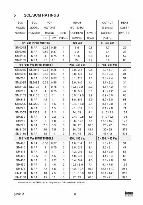
9 SCL/SCM POWER WIRING DIAGRAM
4 5 lb in / 0 5 Nm0 24 in / 6 mm
10 lb in / 1 2 Nm0 35 in / 9 mm
18 lb in / 2 0 Nm0 5 in / 13 mm
15 HP(11 kW)
7 5 10 HP(5 5 7 5 kW)
0 25 5 HP(0 37 4 kW)
L1 L1 L1
InputSingle Phase Models
InputThree Phase Models
208/240V up to 5Hp400/480V up to 7.5Hp
InputThree Phase Models
208/240V 7.5Hp and larger400/480V 10Hp and larger
Output Output
L2/NPE
B- B+
Input AC Voltage Input AC Voltage Input AC Voltage PE lug on heatsinkPE lug on heatsink
L2 L3 B- B+ L2 L3
U V W PE PE
PES
PES
PES
3-PhaseAC Motor
3-PhaseAC Motor
T1 T2 T3 B- B+
+-
DC Bus
Voltage
Torque Requirements
WARNING!• DONOTconnectncomngACpowertooutputtermnalsU,V,W,ortermnals
B+,B-!Severedamagetothedrvewllresult .• Leakagecurrentmayexceed3 .5mAAC .Mnmumszeoftheprotectveearth
(PE)conductorshallcomplywthlocalsafetyregulatonsforhghleakagecurrentequpment .
NOTE• WIRE AND GROUND IN ACCORDANCE WITH NEC OR CEC, AND ALL
APPLICABLELOCALCODES .• MotorwresMUSTberunnaseparatesteelcondutawayfromcontrolwrng
andncomngACpowerwrng .• DonotnstallcontactorsbetweenthedrveandthemotorwthoutconsultngAC
Technologyformorenformaton .Faluretodosomayresultndrvedamage .• UseonlyULandCSAlstedandapprovedwre .• Mnmumwrevoltageratngs300Vfor120,208,and240Vacsystems,and
600Vfor400and480Vacsystems .• Wregaugemustbebasedonamnmumof125%oftheratednput/outputcurrent
ofthedrve,andamnmum75°Cnsulatonratng .Usecopperwreonly .

15 SM01M
10 CONTROL WIRING10.1 Control Wiring vs. Power Wiring
ExternalcontrolwrngMUSTberunnaseparatecondutawayfromallothernputandoutputpowerwrng .Ifcontrolwrngsnotkeptseparatefrompowerwrng,electrcalnosemaybegeneratedonthecontrolwrngthatwllcauseerratcdrvebehavor .UsetwstedwresorsheldedcablegroundedatthedrvechasssONLY .RecommendedcontrolwresBelden8760(2-wre),8770(3-wre),orequvalent .
NOTEControltermnalsprovdebascsolaton(nsulatonperEN61800-5-1) .Protectonaganst contact can only be assured by addtonal measures e .g . supplementalnsulaton .
Strpoff0 .20to0 .25nches(5to6mm)ofnsulatonforcontrolwrng,andtorquethecontroltermnalsto2lb-n(0 .2Nm) .Becarefulnottoovertorquethecontroltermnals,asthswllcausedamagetothetermnalstrp .Thssnotcoveredunderwarrantyandcanonlybereparedbyreplacngthecontrolboard .
10.2 TB-2: Circuit Common
TheTB-2termnalsusedascrcutcommonfortheanalogspeedreferencenputs .IfnecessaryTB-2maybeconnectedtochasssground .
10.3 Surge Suppression on Relays
Currentandvoltagesurgesandspkesnthecolsofcontactors,relays,solenods,etc,nearorconnectedtothedrve,cancauseerratcdrveoperaton .Therefore,asnubbercrcutshouldbeusedoncolsassocatedwththedrve .ForACcols,snubbersshouldconsstofaresstorandacapactornseresacrossthecol .ForDCcols,afree-wheelngorflybackdodeshouldbeplacedacrossthecol .Snubbersaretypcallyavalablefromthemanufacturerofthedevce .
10.4 Start/Stop Control
Therearevarouscontrolschemesthatallowfor2-wreand3-wreStart/Stopcrcuts .RefertothewrngdagramsnSecton11,SCL/SCM CONTROL WIRING DIAGRAMS .
10.5 Speed Reference Signals
Thedrveallowsforthreeanalogspeedreferencenputs:
SPEEDPOT ConnectthewperofaspeedpottotermnalTB-5,andconnectthehghandlowendleadstotermnalsTB-6andTB-2,respectvely .Thespeedpotcanbe2 .5kΩupto10kΩ .
0-10VDC WrethepostvetotermnalTB-5andthenegatvetotermnalTB-2 .TB-5nputmpedances120kΩ .
4-20mA Wre thepostve to termnalTB-25and thenegatve to termnalTB-2 .TB-25nputmpedances250Ω .

SM01M 16
10.6 Speed Reference Selection
Ifananalogspeedreferencenputsusedtocontrolthedrvespeed,termnalTB-13A,13B,or13E(Parameter10,11,or12)maybeprogrammedasthenputselectforthedesredanalognputsgnal .WhenthatTB-13termnalsthenclosedtoTB-11,thedrvewllfollowtheselectedanalogspeedreferencenput .
IfananalogspeedreferencenputsnotselectedonthetermnalstrpusngTB-13A,13B,or13E,speedcontrolwlldefaulttoSTANDARDmode,whchsgovernedbythesettngofSTANDARDSPEEDSOURCE(Parameter05) .TheSTANDARDSPEEDSOURCEcanbetheandbuttonsonthefrontofthedrve,PRESETSPEED#1(Parameter31),a0-10VDCsgnal,ora4-20mAsgnal .
0-10VDCand4-20mAINPUTSIGNALS
TB-13A,TB-13B,andTB-13Ecanallbeprogrammedtoselecta0-10VDCor4-20mAanalogspeedreferencenput .
PRESETSPEEDS
TB-13A can be programmed to select PRESET SPEED #1 (04), TB-13B to selectPRESETSPEED#2(04),andTB-13EtoselectPRESETSPEED#3(04) .Thereareatotalofsevenpresetspeeds,whchareactvatedbydfferentcombnatonsofcontactclosuresbetweenTB-13A,13B,13EandTB-11 .RefertoParameters31-37nSecton15,DESCRIPTION OF PARAMETERS .
JOG
TB-13BcanbeprogrammedtoselectetherJOGFORWARD(07)orJOGREVERSE(08) .TheJogspeedssetbyPRESETSPEED#2(Parameter32) .CloseTB-13BtoTB-11toJOG,andopenthecontacttoSTOP .
WARNING!WhenoperatngnJOGmode,theSTOPsgnalandtheAUXILIARYSTOPfuncton(seeParameters10-12)WILL NOTstopthedrve .Tostopthedrve,removetheJOGcommand .JOG REVERSE wll operate the drve n reverse rotaton even f ROTATIONDIRECTION(Parameter17)ssettoFORWARDONLY .
NOTEIf thedrve s commanded to JOGwhle runnng, thedrvewll enter JOGmodeandrunatPRESETSPEED#2 .WhentheJOGcommandsremoved,thedrvewllSTOP .
MOTOROPERATEDPOT(MOP)/FLOATINGPOINTCONTROL
TB-13BandTB-13Eareusedforthsfuncton,whchcontrolsthedrvespeedusngcontactswredtothetermnalstrp .ProgramTB-13BforDECREASEFREQ(05),andprogramTB-13EforINCREASEFREQ(05) .ClosngTB-13BtoTB-11wllcausethespeedsetponttodecreaseuntlthecontactsopened .ClosngTB-13EtoTB-11wllcausethespeedsetponttoncreaseuntlthecontactsopened .TheINCREASEFREQfunctonwllonlyoperatewhlethedrvesrunnng .

17 SM01M
NOTEIfTB-13A,TB-13B,andTB-13Eareallprogrammedtoselectspeedreferences,andtwoorthreeofthetermnalsareclosedtoTB-11,thehghertermnalhasprortyandwlloverrdetheothers .Forexample,fTB-13Asprogrammedtoselect0-10VDC,andTB-13EsprogrammedtoselectPRESETSPEED#3,closngbothtermnalstoTB-11wllcausethedrvetorespondtoPRESETSPEED#3,becauseTB-13EoverrdesTB-13A .
TheexceptontothsstheMOPfuncton,whchrequrestheuseofTB-13BandTB-13E .ThsleavesTB-13Atobeusedforsomeotherfuncton .IfTB-13Asprogrammedforaspeedreference,andTB-13AsclosedtoTB-11,TB-13AwlloverrdetheMOPfuncton .
10.7 Drive Status Digital Outputs
TheresoneFormArelayattermnalsTB-16andTB-17 .Therelaycontactsarerated3ampsat250Vac .
TermnalTB-13Ecanalsobeconfiguredasadgtaloutput .Thsoutputcrcutsacurrent-sourcngtyperatedat12VDCand50mAmaxmum .
TheFormArelayanddgtaloutputcanbeprogrammedtondcateanyofthefollowng:RUN,FAULT,INVERSEFAULT,FAULTLOCKOUT,ATSPEED,ABOVEPRESETSPEED#3,CURRENTLIMIT,AUTOSPEEDMODE,andREVERSE .RefertoParameters06and12nSecton15,DESCRIPTION OF PARAMETERS .
ThedagrambelowllustrateshowTB-13E,whenconfiguredasadgtaloutput,canbeusedtodrveanexternalrelay:
Diode Snubber(1N4148 or Equivalent)
TB-2
TB-13E
Relay Coil
SCL/
SCM
Ter
min
al S
trip
TB-13EusedtoDrveanExternalRelay

SM01M 18
11 SCL/SCM CONTROL WIRING DIAGRAMS11.1 SCL/SCM Terminal Strip
Shownbelowsthecontroltermnalstrp,alongwthabrefdescrptonofthefunctonofeachtermnal .Thefollowngwrngdagramexamplesprovdeaquckreferencetowrethedrveforthemostcommonconfiguratons .
MaintainedRUN/STOP
Contact
1 2 2513A 13E13B
RUN
5 6 11 16 17
SIG
NAL
COM
MON
0-10
V DC
INPU
T
TB-1
3A F
UNCT
ION
SELE
CT
TB-1
3B F
UNCT
ION
SELE
CT
TB-1
3E F
UNCT
ION
SELE
CT
4-20
mA
INPU
T
FORM A RELAY
- + +
SPEE
D PO
T PO
WER
SUP
PLY
DIGI
TAL
INPU
T RE
FERE
NCE
SCL/SCMTermnalStrp
NOTE• ThefunctonoftermnalsTB-13A,13B,13EandtheFormArelayattermnals
16 and 17 are dependent on the programmng of certan parameters .RefertoSecton15,DESCRIPTION OF PARAMETERS .
• Thedgtalnputs(termnals1,13A,13B,and13E)areactve-hgh .Theycanbeactvatedusngtermnal11(whchs+12VDC)asshownnthefollowngdagrams,orbyusnganexternalvoltagesourcewtharangeof+12VDCto+28VDC(+10%) .

19 SM01M
11.2 Two-Wire Start/Stop Control
MaintainedRUN/STOP
Contact(FORWARD)
1 2 2513A 13E13B
RUN
5 6 11 16 17
SIG
NAL
COM
MON
0-10
V DC
INPU
T
TB-1
3A F
UNCT
ION
SELE
CT
TB-1
3B F
UNCT
ION
SELE
CT
TB-1
3E F
UNCT
ION
SELE
CT
4-20
mA
INPU
T
FORM A RELAY
- + +
SPEE
D PO
T PO
WER
SUP
PLY
DIGI
TAL
INPU
T RE
FERE
NCE
MaintainedRUN/STOP
Contact(REVERSE)
RUN
REVE
RSE
2-WreStart/StopControl
NOTE• CloseTB-1toTB-11toRUN,andopentoSTOP .TB-1functonsasaRUN
nputfortwo-wrestart/stopcrcuts,andaSTOPnputforthree-wrestart/stopcrcuts .RefertoSecton11 .3
• Ifreversedrectonsrequred,setROTATION(Parameter17)toFORWARDANDREVERSE(02),andprogramTB-13A(Parameter10)toRUNREVERSE(06) . CloseTB-13AtoTB-11toRUNnthereversedrecton,andopentoSTOP .
• For0-10VDCor4-20mAspeedcontrol,setSTANDARDSPEEDSOURCE(Parameter05)to0-10VDC(03)or4-20mA(04) .

SM01M 20
11.3 Three-Wire Start/Stop Control
MomentarySTOP
Contact
1 2 2513A 13E13B
STOP
5 6 11 16 17
SIG
NAL
COM
MON
0-10
V DC
INPU
T
TB-1
3A F
UNCT
ION
SELE
CT
TB-1
3B F
UNCT
ION
SELE
CT
TB-1
3E F
UNCT
ION
SELE
CT
4-20
mA
INPU
T
FORM A RELAY
- + +
SPEE
D PO
T PO
WER
SUP
PLY
DIGI
TAL
INPU
T RE
FERE
NCE
MomentarySTARTContact
(STA
RT R
EVER
SE)
REV FWD(S
TART
FOR
WAR
D)
3-WreStart/StopControl
NOTE• ProgramTB-13E(Parameter12)forSTARTFORWARD(06) .• Ifreversedrectonsrequred,setROTATION(Parameter17)toFORWARD
AND REVERSE (02), and program TB-13A (Parameter 10) for STARTREVERSE(07) .
• MomentarlycloseTB-13EtoTB-11toSTARTntheforwarddrecton,orcloseTB-13AtoTB-11toSTARTnthereversedrecton .MomentarlyopenTB-1toTB-11toSTOPthedrve .
• For0-10VDCor4-20mAspeedcontrol,setSTANDARDSPEEDSOURCE(Parameter05)to0-10VDC(03)or4-20mA(04) .

21 SM01M
11.4 Preset Speeds & Speed Pot (2-Wire Start/Stop Control)
MaintainedRUN/STOP
Contact
1 2 2513A 13E13B
RUN
5 6 11 16 17
SIG
NAL
COM
MON
0-10
V DC
INPU
T
TB-1
3A F
UNCT
ION
SELE
CT
TB-1
3B F
UNCT
ION
SELE
CT
TB-1
3E F
UNCT
ION
SELE
CT
FORM A RELAY
SPEE
D PO
T PO
WER
SUP
PLY
DIGI
TAL
INPU
T RE
FERE
NCE
(PRE
SET
SPEE
D #1
)
(PRE
SET
SPEE
D #2
)
(PRE
SET
SPEE
D #3
)SPEED
POT
SpeedPotentometer
NOTE:• For preset speed control, all or some of the TB-13 termnals must be
programmedaspresetspeedselects .Ifonlytwoorthreepresetspeedsarerequred,onlytwooftheTB-13termnalsmustbeused .RefertothetablenthedescrptonofParameters31-37nSecton15 .
• ProgramthePRESETSPEEDS(Parameters31-37)tothedesredvalues .• Ifspeedpotcontrolsdesredwhennoneofthepresetspeedsareselected(all
presetspeedselectsareopentoTB-11),setSTANDARDSPEEDSOURCE(Parameter05)to0-10VDC(03) .

SM01M 22
12 INITIAL POWER UP AND MOTOR ROTATION
DANGER!Hazardofelectrcalshock!Watthreemnutesafterdsconnectngncomngpowerbeforeservcngdrve .Capactorsretanchargeafterpowersremoved .
STOP!• DO NOT connect ncomng AC power to output termnals U, V, and W or
termnalsB+,B-!Severedamagetothedrvewllresult .Donotcontnuouslycyclenputpowertothedrvemorethanonceeverytwomnutes .Damagetothedrvewllresult .
• Severe damage to the drve can result f t s operated after a longperod of storage or nactvty wthout reformng the DC bus capactors!RefertoSecton6 .1,Installation After a Long Period of Storage
Beforeattemptngtooperatethedrve,motor,anddrvenequpment,besureallprocedurespertanngtonstallatonandwrnghavebeenproperlyfollowed .
Dsconnectthedrvenloadfromthemotor .Verfythatthedrvenputtermnals(L1andL2/N,orL1,L2,andL3)arewredtothepropernputvoltageperthenameplateratngofthedrve .
Energzethencomngpowerlne .TheLEDdsplaywllflashathreedgtnumber(320ntheexamplebelow)thatdentfiestheparameterversoncontanednthedrve .Thedsplayshouldthenread“---”,whchndcatesthatthedrvesnaSTOPcondton .Thssshownbelow:
Applynputpower
Dsplaythenreads"---"
Dsplayflashesparameterverson(300-399)
Followths4-stepproceduretocheckthemotorrotaton .Thsprocedureassumesthatthedrvehasbeenpoweredupforthefirsttme,andthatnoneoftheparametershavebeenchanged .
1 . Usethebuttontodecreasethespeedsetpontto00 .0Hz .Theleftdecmalpontwllllumnateasthespeedsetpontsdecreased .Ifthebuttonshelddown,thespeedsetpontwlldecreasebytenthsofHzuntlthenextwholeHzsreached,andthentwlldecreasebyoneHzncrements .Otherwse,eachpushofthebuttonwlldecreasethespeedsetpontbyatenthofaHz .
Once00 .0Hz s reached, thedsplaywll togglebetween“00 .0”and“- - -”,whchndcatesthatthedrvesnaSTOPcondtonwthaspeedsetpontof00 .0Hz .
2 . Gve thedrveaSTARTcommand .ThscanbedoneusngoneofseveralwrngmethodsdescrbednSecton11,SCL/SCM CONTROL WIRING DIAGRAMS .OncetheSTARTcommandsssued,thedsplaywllread“00 .0”,ndcatngthatthedrvesnaRUNcondtonwthaspeedsetpontof00 .0Hz .

23 SM01M
3 . Usethebuttontoncreasethespeedsetpontuntlthemotorstartstorotate .Theleftdecmalpontwlllghtasthespeedsetpontsncreased .Ifthebuttonshelddown,thespeedsetpontwllncreasebytenthsofHzuntlthenextwholeHzsreached,andthentwllncreasebyoneHzncrements .Otherwse,eachpushofthebuttonwllncreasethespeedsetpontbyatenthofaHz .
4 . Ifthemotorsrotatngnthewrongdrecton,gvethedrveaSTOPcommandandremovepowerfromthedrve .Watthreemnutesforthebuscapactorstodscharge,andswapanytwoofthemotorwresconnectedtoU,V,W .
NOTEThedrvesphasensenstvewthrespecttoncomnglnevoltage .Thsmeansthatthedrvewlloperatewthanyphasesequenceofthencomngthreephasevoltage .Therefore,tochangethemotorrotaton,thephasesmustbeswappedatthedrveoutputtermnalsoratthemotor .

SM01M 24
13 PROGRAMMING THE SCL/SCM DRIVE
Thedrvemaybeprogrammedbyoneoftwomethods:usngthethreebuttonsand3-dgtLEDdsplayon the frontof thedrve,orbyprogrammng theElectroncProgrammngModule(EPM)usngtheoptonalEPMProgrammer .Thssectondescrbesprogrammngthedrveusngthebuttonsanddsplay,whchareshownbelow:
BUTTONS DISPLAY
Mode
ToenterthePROGRAMmodetoaccesstheparameters,presstheModebutton .ThswllactvatethePASSWORDprompt(fthepasswordhasnotbeendsabled) .Thedsplaywllread“00”andtheupperrght-handdecmalpontwllbeblnkng,asshownbelow:
PressMode
Upperrghtdecmalpontblnks
Dsplayreads"00"
Usetheandbuttonstoscrolltothepasswordvalue(thefactorydefaultpasswords“225”)andpresstheModebutton .Oncethecorrectpasswordvaluesentered,thedsplaywllread"P01",whchndcatesthatthePROGRAMmodehasbeenaccessedatthebegnnngoftheparametermenu(P01sthefirstparameter) .Thssshownbelow:
PressModetoenterpassword
Useandtoscrolltothepasswordvalue
Parametermenusaccessedatthefirstparameter
NOTEIfthedsplayflashes“Er”,thepasswordwasncorrect,andtheprocesstoenterthepasswordmustberepeated .

25 SM01M
Usetheandbuttonstoscrolltothedesredparameternumber .Intheexamplebelow,Parameter19sbengdsplayed,whchstheACCELERATIONTIMEofthedrve:
Useandtoscrolltothedesredparameternumber(theexamplesParameter19-ACCELERATIONTIME)
Oncethedesredparameternumbersfound,presstheModebuttontodsplaythepresentparametersettng .Theupperrght-handdecmalpontwllbegnblnkng,ndcatngthatthepresentparametersettngsbengdsplayed,andthat tcanbechangedbyusngtheandbuttons .
PressModetodsplaypresentparametersettng(exampleset-tngs20 .0)
Upperrghtdecmalpontblnks
Useandtochangesettng(examplesettngchangedto30 .0)
PressModetostorenewsettng
PressngModewllstorethenewsettngandalsoextthePROGRAMmode .Tochangeanother parameter, press theMode key agan to re-enter the PROGRAM mode (theparametermenuwllbeaccessedattheparameterthatwaslastvewedorchangedbeforeextng) .IftheMode keyspressedwthntwomnutesofextngthePROGRAMmode,thepasswordsnotrequredaccesstheparameters .Aftertwomnutes,thepasswordmustbeenterednordertoaccesstheparametersagan .
13.1 Setting Values in Tenths of Units Above 100
Parametersettngsandthekeypadspeedcommandcanalwaysbeadjustedntenthsofuntncrementsfrom0 .0to99 .9 .Above100however,valuescanbesetnwholeuntsortenthsofunts,dependngonthesettngofParameter16-UNITSEDITING .
IfParameter16-UNITSEDITINGssettoWHOLEUNITS(02),parametervaluesandthekeypadspeedcommandcanonlybeadjustedbywholeuntncrementsabove100 .Forexample,Parameter19-ACCELERATIONTIMEcouldnotbesetto243 .7seconds .Itcouldonlybesetto243or244seconds .Lkewse,thekeypadspeedcommand(setusngtheandbuttons)couldnotbesetto113 .4Hz .Itcouldonlybesetto113or114Hz .

SM01M 26
If,however,Parameter16-UNITSEDITINGssettoTENTHSOFUNITS(01),parametervaluesandthekeypadspeedcommandcanbeadjustedntenthsofuntncrementsuptoavalueof1000(above1000,wholeuntncrementsonly) .Eachpushoftheorbuttonwlladjustthevaluebyonetenthofaunt .Iftheorbuttonspressedandheld,thevaluewllncrementbytenthsofuntsuntlthenextwholeuntsreached,andthenthevaluewllncrementbywholeunts .
Whenavalueabove100sbengadjustedbytenthsofunts,thevaluesshftedtotheleftbyonedgtsothatthetenthsportonofthevaluecanbedsplayed .Thsresultsnthefirstdgt(readngfromlefttorght)ofthevaluedsappearngfromthedsplay .Also,the lowerdecmalpontwllblnk to ndcate that theactualvalue sabove100 .Oncethevaluesnolongerbengadjusted,thevaluewllshftbacktotherghtandthetenthsportonofthevaluewlldsappear .
Intheexamplebelow,Parameter19-ACCELERATIONTIMEspresentlysetto243 .0seconds,andsbengncreasedto243 .7seconds .
GotoParameter19andpressModetoseepresentsettng("243"seconds)
Upperrghtdecmalpontblnks
Pressbuttontoseetenthsporton
Upperrghtdecmalpontandlowerdecmalpontblnk
Valueshftstotheleft("2"dsappears)
Pressbuttontoscrollupto"43 .7"
PressModetostorenewvalue
13.2 Electronic Programming Module (EPM)
EverySCL/SCMSeresdrvehasanElectroncProgrammngModule(EPM)nstalledonthemancontrolboard .TheEPMstorestheuser’sparametersettngsandspecalOEMdefault settngs (fprogrammed) .TheEPM s removable,allowng t tobe nstalled nanotherdrveforquckset-up .Forexample,fadrvesbengreplacedwthanewone,theEPMcanbetakenoutofthefirstdrveandnstallednthenewdrve .Downtmesmnmzedbecausethenewdrvedoesnotrequreprogrammng-tsreadytorunwhentheEPMsnstalled .

27 SM01M
TheSCL/SCMSeresdrvecontanstwoorthreesetsofparametervalues,dependngonwhetherthedrvehasbeenprogrammedwthoptonalOEMdefaultsettngs .Thefirstsetofvaluessthefactorydefaultsettngs,whcharepermanentlystoredonthemancontrolboardandcannotbechanged .Thesecondsetofvaluesstheusersettngs,whcharestoredntheEPM .Whenthedrveleavesthefactory,theusersettngsarethesameasthefactorydefaultsettngs,buttheusersettngscanbechangedtoconfigurethedrveforapartcularapplcaton .TheoptonalthrdsetofvaluesstheOEMdefaultsettngs,whcharealsostoredntheEPM .OEMdefaultsettngsaretypcallyusedncaseswheremanydrvesareusedforthesameapplcaton,whchrequresthatallofthedrveshavethesameparametersettngs .TheOEMdefaultsettngscannotbechangedwthouttheoptonalEPMProgrammer .ThedrvecanbeprogrammedtooperateaccordngtotheusersettngsortheOEMdefaultsettngs(RefertoParameter48nSecton15) .
NOTEThedrvewllnotoperatewthouttheEPMnstalled .Thedrvewlldsplay“F1”ftheEPMsmssngordamaged .
STOP!DonotremovetheEPMwhlepowersappledtothedrve .DamagetotheEPMand/ordrvemayresult .
TheoptonalEPMProgrammerhastheabltytoqucklyandeaslyprogrammanySCSeresdrvesforthesameconfiguraton .Oncea“master”EPMsprogrammedwththedesredparametersettngs,theEPMProgrammercanthencopythosesettngstootherEPMs,allowngmanydrvestobeconfiguredveryquckly .ConsulttheEPMProgrammerInstructonManualorcontactthefactoryformorenformaton .
IftheOEMsettngsntheEPMbecomecorrupted,thedrvewlloperatenormally,untlanattemptsmadetoperformaRESETOEMusngParameter48,PROGRAMSELECTION .Thedrvewllthenflash“GF”tondcatethattheOEMsettngsarenolongervald .TheEPMmustthenbere-programmedusngtheoptonalEPMProgrammer .
IftheOEMsettngsandtheusersettngsarebothcorrupted,thedrvewlldsplay“GF”mmedatelyandthedrvewllrequreaRESET60orRESET50usngParameter48,PROGRAMSELECTION .OncetheRESETsperformed,theparameterscanthenbeprogrammedndvduallytomatchtheOEMdefaultsettngs .ThswllallowthedrvetooperateasftwerenOEMmode,eventhoughtsactuallyoperatngnUSERmode .RefertoParameter48nSecton15,DESCRIPTION OF PARAMETERS .
NOTEThedrvewllalsodsplay“GF”faRESETOEMorOPERATEWITHOEMSETTINGSsattemptedwhentheEPMdoesnotcontanOEMdefaults .
SM01M 28
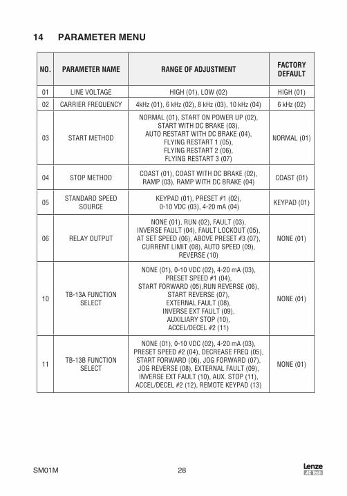
14 PARAMETER MENU
NO. PARAMETER NAME RANGE OF ADJUSTMENT FACTORYDEFAULT
01 LINE VOLTAGE HIGH (01), LOW (02) HIGH (01)
02 CARRIER FREQUENCY 4kHz (01), 6 kHz (02), 8 kHz (03), 10 kHz (04) 6 kHz (02)
03 START METHOD
NORMAL (01), START ON POWER UP (02), START WITH DC BRAKE (03),
AUTO RESTART WITH DC BRAKE (04), FLYING RESTART 1 (05), FLYING RESTART 2 (06), FLYING RESTART 3 (07)
NORMAL (01)
04 STOP METHOD COAST (01), COAST WITH DC BRAKE (02),RAMP (03), RAMP WITH DC BRAKE (04) COAST (01)
05 STANDARD SPEED SOURCE
KEYPAD (01), PRESET #1 (02), 0-10 VDC (03), 4-20 mA (04) KEYPAD (01)
06 RELAY OUTPUT
NONE (01), RUN (02), FAULT (03), INVERSE FAULT (04), FAULT LOCKOUT (05), AT SET SPEED (06), ABOVE PRESET #3 (07),
CURRENT LIMIT (08), AUTO SPEED (09), REVERSE (10)
NONE (01)
10 TB-13A FUNCTION SELECT
NONE (01), 0-10 VDC (02), 4-20 mA (03), PRESET SPEED #1 (04),
START FORWARD (05),RUN REVERSE (06), START REVERSE (07), EXTERNAL FAULT (08),
INVERSE EXT FAULT (09), AUXILIARY STOP (10), ACCEL/DECEL #2 (11)
NONE (01)
11 TB-13B FUNCTION SELECT
NONE (01), 0-10 VDC (02), 4-20 mA (03), PRESET SPEED #2 (04), DECREASE FREQ (05), START FORWARD (06), JOG FORWARD (07), JOG REVERSE (08), EXTERNAL FAULT (09), INVERSE EXT FAULT (10), AUX. STOP (11),
ACCEL/DECEL #2 (12), REMOTE KEYPAD (13)
NONE (01)

29 SM01M
NO. PARAMETER NAME RANGE OF ADJUSTMENT FACTORYDEFAULT
12
TB-13E INPUT FUNCTIONS
NONE (01), 0-10 VDC (02), 4-20 mA (03), PRESET SPEED #3 (04), INCREASE FREQ (05), START FORWARD (06), EXTERNAL FAULT (07),
INVERSE EXT FAULT (08), AUX. STOP (09),ACCEL/DECEL #2 (10),
NONE (01)TB-13E OUTPUT FUNCTIONS
RUN (11), FAULT (12), INVERSE FAULT (13), FAULT LOCKOUT (14), AT SET SPEED (15),
ABOVE PRESET #3 (16), CURRENT LIMIT (17), AUTO SPEED (18), REVERSE (19),
DYNAMIC BRAKING (20),
OTHER FUNCTIONS REMOTE KEYPAD (21)
14 CONTROL TERMINAL STRIP ONLY (01) REMOTE KEYPAD ONLY (02)
TERMINAL STRIP ONLY
(01)
16 UNITS EDITING TENTHS OF UNITS (01), WHOLE UNITS (02) WHOLE UNITS (02)
17 ROTATION FORWARD ONLY (01), FORWARD AND REVERSE (02)
FORWARD ONLY (01)
19 ACCELERATION TIME 0.1 - 3600.0 SEC 20.0 SEC
20 DECELERATION TIME 0.1 - 3600.0 SEC 20.0 SEC
21 DC BRAKE TIME 0.0 - 3600.0 SEC 0.0 SEC
22 DC BRAKE VOLTAGE 0.0 - 30.0 % 0.0 %
23 MINIMUM FREQUENCY 0.0 - MAXIMUM FREQUENCY 0.0 Hz
24 MAXIMUM FREQUENCY MINIMUM FREQUENCY - 240 Hz SCL = 50.0 Hz SCM = 60.0 Hz
25 CURRENT LIMIT 30 - 180 % 180 %
26 MOTOR OVERLOAD 30 - 100 % 100 %
27 BASE FREQUENCY 25.0 - 500.0 Hz SCL = 50.0 Hz SCM = 60.0 Hz
28 FIXED BOOST 0.0 - 30.0 % 1.0 %
29 ACCEL BOOST 0.0 - 20.0 % 0.0 %

SM01M 30
NO. PARAMETER NAME RANGE OF ADJUSTMENT FACTORYDEFAULT
30 SLIP COMPENSATION 0.0 - 5.0 % 0.00 %
31-37 PRESET SPEEDS 0.0 - MAXIMUM FREQUENCY 0.0 Hz
38 SKIP BANDWIDTH 0.0 - 10.0 Hz 0.0 Hz
39 SPEED SCALING 0.0 - 6500.0 0.0
42 ACCEL/DECEL #2 0.1 - 3600.0 SEC 20.0 SEC
44 PASSWORD 000 - 999 225
45 SPEED AT MIN SIGNAL MINIMUM FREQUENCY - 999Hz 0.0Hz
46 SPEED AT MAX SIGNAL MINIMUM FREQUENCY - 999Hz SCL = 50 Hz SCM = 60 Hz
47 CLEAR HISTORY MAINTAIN (01), CLEAR (02) MAINTAIN (01)
48 PROGRAM SELECTION
USER SETTINGS (01) OEM SETTINGS (02)
RESET OEM (03), RESET 60 (04) RESET 50 (05), TRANSLATE (06)
SCL = RESET 50 (05)
SCM = RESET 60 (04)
50 FAULT HISTORY (VIEW-ONLY) (N/A)
51 SOFTWARE CODE (VIEW-ONLY) (N/A)
52 DC BUS VOLTAGE (VIEW-ONLY) (N/A)
53 MOTOR VOLTAGE (VIEW-ONLY) (N/A)
54 LOAD (VIEW-ONLY) (N/A)
55 0-10 VDC INPUT (VIEW-ONLY) (N/A)
56 4-20 mA INPUT (VIEW-ONLY) (N/A)
57 TB STRIP STATUS (VIEW-ONLY) (N/A)
58 KEYPAD STATUS (VIEW-ONLY) (N/A)

31 SM01M
15 DESCRIPTION OF PARAMETERS
P01 LINE VOLTAGE SELECTION
ParameterP01calbratesthedrvefortheactualapplednputvoltage .SetthsparametertoHIGH(01) for120,220-240,and460-480Vac nput,orLOW(02) for200-208and380-415Vacnput .
NOTEIfthsparameterschangedwhlethedrvesrunnng,thenewvaluewllnottakeeffectuntlthedrvesstopped .
P02 CARRIER FREQUENCY
Parameter P02 sets the swtchng rate of the output IGBT’s . Increasng the carrerfrequencywllresultnlessaudblemotornose .Avalablesettngsare:4kHz,6kHz,8kHz,and10kHz .
PARAMETERSETTING
CARRIER FREQUENCY
AMBIENT OR OUTPUT DERATE
01 4 kHz 40°C or 100%
02 6 kHz 40°C or 100%
03 8 kHz 40°C or 100%
04 10 kHz 35°C or 92%
NOTE• TheSCL/SCMdrvesfullyratedupto8kHzcarrerfrequency .Ifthe10kHz
carrerfrequencysselected,thedrve’sambenttemperatureratngORoutputcurrentratngmustbede-ratedtothevalueshownnthetableabove .
• Ifthsparameterschangedwhlethedrvesrunnng,thechangewllnottakeeffectuntlthedrvesstopped .
P03 START METHOD
WARNING!Automatcstartngofequpmentmaycausedamagetoequpmentand/ornjurytopersonnel!Automatcstartshouldonlybeusedonequpmentthatsnaccessbletopersonnel .
01 NORMAL:Thedrvewllstartwhentheappropratecontactsclosedonthetermnalstrp .SeeSecton11forpossblecontrolconfiguratons .
02 STARTONPOWERUP:Thedrvewllautomatcallystartuponapplcatonofnputpower .

SM01M 32
03 STARTWITHDCBRAKE:WhenaSTARTcommandsgven,thedrvewllapplyDCBRAKEVOLTAGE(Parameter22)fortheduratonofDCBRAKETIME(Parameter21)prortostartngthemotortoensurethatthemotorsnotturnng .
04 AUTORESTARTWITHDCBRAKING:UponaSTARTcommand,afterafault,oruponapplcatonofpower,thedrvewllapplyDCBRAKEVOLTAGE(Parameter22)fortheduratonofDCBRAKETIME(Parameter21)prortostartng(orrestartng)themotor .
05 FLYINGRESTART1:LOWperformance .Slowestsynchronzatonandlowestcurrentlevel .Thssettngresultsnthesmoothestsynchronzaton .
06 FLYING RESTART 2: MEDIUM performance . Faster synchronzaton andhgher current level . Ths settng allows faster synchronzaton whle retanngsmoothness .
07 FLYINGRESTART3:HIGHperformance .Fastestsynchronzatonandhghestcurrentlevel .Thssettngallowsthefastestsynchronzaton,butsacrficessmoothness .
Whenprogrammedforauto-restart(settngs04-07),thedrvewllattemptthreerestartsaftera fault .The ntervalbetweenrestartattempts s15seconds forsettng04,and2secondsforsettngs05,06and07 .Durngthentervalbetweenrestartattempts,thedsplaywllread“SP”tondcateStartPendng .Ifallthreerestartattemptsfal,thedrvewlltrpntoFAULTLOCKOUT(dsplayed“LC”)andrequreamanualreset .RefertoSecton16,TROUBLESHOOTING .
TheFLYINGRESTART1-3settngsallowthedrvetostartntoaspnnngloadafterafaultoruponapplcatonofnputpower .Theydffernthetmerequredtofindthemotorspeedandtheamountofcurrentrequredtosynchronzewtht .Thefasterthedrveattemptstofindthemotorspeed,themorecurrentsrequred .Thefirsttworestartattemptswlltrytostartntothespnnngload,butthethrdrestartattemptwllactlkeAUTORESTARTWITHDCBRAKING .
NOTESettngs02and04-07requreatwo-wrestart/stopcrcuttooperate .TheRUNcontactmust remanclosed for thepower-upstartandauto-restart functons tooperate .
P04 STOP METHOD
01 COASTTOSTOP:WhenaSTOPcommandsgven,thedrveshutsofftheoutputtothemotor,allowngttocoastfreelytoastop .
02 COASTWITHDCBRAKE:Whenastopcommandsgven,thedrvewllactvateDC brakng (after a delay of up to 2 seconds, dependng on frequency) to helpdeceleratetheload .RefertoParameters:21-DCBRAKETIME,and22-DCBRAKEVOLTAGE .
03 RAMPTOSTOP:Whenastopcommandsgven,thedrvewlldeceleratethemotortoastopattheratedetermnedbyParameter20-DECELERATIONTIME .

33 SM01M
04 RAMPWITHDCBRAKE:Whenastopcommandsgven,thedrvewlldeceleratethemotordownto0 .2Hz(attheratesetbyParameter20-DECELERATIONTIME)andthenactvateDCbrakngaccordngtothesettngsofParameters21-DCBRAKETIMEand22-DCBRAKEVOLTAGE .Thssusedtobrngtheloadtoafinalstop,asthemotormaystllbeturnngslghtlyafterthedrvestops .
P05 STANDARD SPEED SOURCE
P05selectsthespeedreferencesourcewhenthedrvesnSTANDARDspeedmode .Thefollowngspeedreferencescanbeselected:
01 KEYPAD:Usetheandbuttonstoscrolltothedesredspeed .
02 PRESETSPEED#1:DrvewlloperateatthefrequencysetnParameter31 .
03 0-10VDC:Drvewllrespondtoa0-10VDCsgnalwredtoTB-5(+)andTB-2(-) .
04 4-20mA:Drvewllrespondtoa4-20mAsgnalwredtoTB-25(+)andTB-2(-) .
P06 RELAY OUTPUT
P06selectsthestatusndcatonforthenormallyopenrelayoutputatTB-16andTB-17:
01 NONE:Dsablestherelayoutput .
02 RUN:ClosesuponaSTARTcommand .OpensfthedrvesnaSTOPstate,thedrvefaults,ornputpowersremoved .DCbrakngsconsderedaSTOPstate .
03 FAULT:Closesftheresnofaultcondton .Opensfthedrvefaults,ornputpowersremoved .
04 INVERSEFAULT:Closesfthedrvefaults .Opensftheresnofaultcondton .
05 FAULTLOCKOUT:Closeswhennputpowersappled .Opensfthreerestartattemptsareunsuccessful,orfnputpowersremoved .
06 ATSETSPEED:Closesfthedrveswthn+0 .5Hzofthespeedsetpont .
07 ABOVE PRESET SPEED #3: Closes f the output frequency exceeds PRESETSPEED#3(Parameter33) .OpensftheoutputfrequencysequaltoorlessthanPRESETSPEED#3 .
08 CURRENTLIMIT:ClosesftheoutputcurrentexceedstheCURRENTLIMITsettng .OpensftheoutputcurrentsequaltoorlessthanCURRENTLIMIT(seeParameter25) .
09 AUTOMATIC SPEED MODE: Closes f an AUTOMATIC (termnal strp) speedreference s actve . Opens f a STANDARD (Parameter 5) speed reference sactve .
10 REVERSE:Closeswhenreverserotatonsactve .Openswhenforwardrotatonsactve(seeParameter17-ROTATIONDIRECTION) .

SM01M 34
P10 TB-13A FUNCTION SELECT
P10selectsthefunctonoftermnalTB-13A .ClosngTB-13AtoTB-11(oropenngnthecaseofsettngs08and10)actvatestheselectedfuncton .Thefollowngfunctonscanbeselected:
01 NONE:DsablestheTB-13Afuncton .
02 0-10 VDC: Selects a 0-10 VDC sgnal (at TB-5) as the AUTO speed referencenput .
03 4-20mA:Selectsa4-20mAsgnal(atTB-25)astheAUTOspeedreferencenput .
04 PRESETSPEED#1:SelectsPRESETSPEED#1asthespeedreference .ThedrvewlloperateatthefrequencyprogrammedntoParameter31 .
05 STARTFORWARD:Setsupthedrvefora3-wrestart/stopcrcut .MomentarlycloseTB-13AtoTB-11tostartthedrve,andmomentarlyopenTB-1toTB-11tostop .
06 RUNREVERSE:CloseTB-13AtoTB-11torunnthereversedrecton,andopentostop .CloseTB-1toTB-11torunntheforwarddrectonandopentostop .
07 STARTREVERSE:MomentarlycloseTB-13AtoTB-11tostartthedrventhereversedrecton,andmomentarlyopenTB-1toTB-11tostop .Parameter17-ROTATIONmustbeset toFORWARDANDREVERSE (02), andTB-13Emustbeused forSTARTFORWARD .
08 EXTERNALFAULT:SetsTB-13Aasanormallyclosedexternalfaultnput .OpenTB-13AtoTB-11totrpthedrve .
09 INVERSEEXTERNALFAULT:SetsTB-13Aasanormallyopenexternalfaultnput .CloseTB-13AtoTB-11totrpthedrve .
10 AUXILIARYSTOP:WhenTB-13AsopenedwthrespecttoTB-11,thedrvewlldeceleratetoaSTOP(evenfSTOPMETHODssettoCOAST)attheratesetntoACCEL/DECEL#2(Parameter42) .
11 ACCEL/DECEL#2:SelectstheacceleratonanddeceleratontmeprogrammedntoACCEL/DECEL#2(Parameter42) .
P11 TB-13B FUNCTION SELECT
P11selectsthefunctonoftermnalTB-13B .ClosngTB-13BtoTB-11(oropenngnthecaseofsettngs09and11)actvatestheselectedfuncton .Thefollowngfunctonscanbeselected:
01 NONE:DsablestheTB-13Bfuncton .
02 0-10 VDC: Selects a 0-10 VDC sgnal (at TB-5) as the AUTO speed referencenput .
03 4-20mA:Selectsa4-20mAsgnal(atTB-25)astheAUTOspeedreferencenput .
04 PRESETSPEED#2:SelectsPRESETSPEED#2asthespeedreference .ThedrvewlloperateatthefrequencyprogrammedntoParameter32 .

35 SM01M
05 DECREASEFREQ:ClosngTB-13BtoTB-11wlldecreasethespeedsetpontuntlthecontactsopened .TB-13EmustbeprogrammedforINCREASEFREQ .
06 STARTFORWARD:Setsupthedrvefora3-wrestart/stopcrcut .MomentarlycloseTB-13BtoTB-11tostartthedrve,andmomentarlyopenTB-1toTB-11tostop .
07 JOGFORWARD:CloseTB-13BtoTB-11toJOGntheforwarddrecton .ThedrvewllrunatPRESETSPEED#2(Parameter32)whennJOGmode .
08 JOGREVERSE:CloseTB-13BtoTB-11toJOGnthereversedrecton .ThedrvewllrunatPRESETSPEED#2(Parameter32)whennJOGmode .
WARNING!• WhenoperatngnJOGmode,theSTOPsgnalandtheAUXILIARYSTOP
functon(seeParameters10-12)WILL NOTstopthedrve .Tostopthedrve,removetheJOGcommand .
• JOGREVERSEwlloperatethedrvenreverserotatonevenfROTATIONDIRECTION(Parameter17)ssettoFORWARDONLY .
09 EXTERNALFAULT:SetsTB-13Basanormallyclosedexternalfaultnput .OpenTB-13BtoTB-11totrpthedrve .
10 INVERSEEXTERNALFAULT:SetsTB-13Basanormallyopenexternalfaultnput .CloseTB-13BtoTB-11totrpthedrve .
11 AUXILIARYSTOP:WhenTB-13BsopenedwthrespecttoTB-11,thedrvewlldeceleratetoaSTOP(evenfSTOPMETHODssettoCOAST)attheratesetntoACCEL/DECEL#2(Parameter42) .
12 ACCEL/DECEL#2:SelectstheacceleratonanddeceleratontmeprogrammedntoParameter42-ACCEL/DECEL#2 .
13 REMOTEKEYPAD:WhentheRemoteKeypadoptonsbengused,TB-13Bmustbe set to ths functon . Also, TB-13E (Parameter 12) must be set for REMOTEKEYPAD(21),andCONTROL(Parameter14)mustbesettoREMOTEKEYPADONLY(02) .
NOTEIfthedrvescommandedtoJOGwhlerunnng,thedrvewllenterJOGmodeandrunatPRESETSPEED#2(Parameter32) .WhentheJOGcommandsremoved,thedrvewllSTOP .
P12 TB-13E FUNCTION SELECT
ParameterP12selectsthefunctonoftermnalTB-13E .Thstermnalcanbeconfiguredasadgtalnput(settngs01to10)oradgtalstatusoutput(settngs11to20) .Whenusedasannput,closngTB-13EtoTB-11(oropenngnthecaseofsettngs07and09)actvatestheselectedfuncton .
Whenusedasanoutput,P12canprovdethedrve'sstatusformontorng .IftheRemoteKeypadoptonsbengused,thsparametermustbesettoREMOTEKEYPAD(21) .

SM01M 36
ThefollowngnputfunctonscanbeselectedforP12:
01 NONE:DsablestheTB-13Efuncton .
02 0-10 VDC: Selects a 0-10 VDC sgnal (at TB-5) as the AUTO speed referencenput .
03 4-20mA:Selectsa4-20mAsgnal(atTB-25)astheAUTOspeedreferencenput .
04 PRESETSPEED#3:SelectsPRESETSPEED#3asthespeedreference .ThedrvewlloperateatthefrequencyprogrammedntoParameter33 .
05 INCREASEFREQ:ClosngTB-13EtoTB-11wllncreasethespeedsetpontuntlthecontactsopened .INCREASEFREQwllonlyworkwhenthedrvesrunnng .TB-13BmustbeprogrammedforDECREASEFREQ .
06 STARTFORWARD:Setsupthedrvefora3-wrestart/stopcrcut .MomentarlycloseTB-13EtoTB-11tostartthedrve,andmomentarlyopenTB-1toTB-11tostop .
07 EXTERNALFAULT:SetsTB-13Easanormallyclosedexternalfaultnput .OpenTB-13EtoTB-11totrpthedrve .
08 INVERSEEXTERNALFAULT:SetsTB-13Easanormallyopenexternalfaultnput .CloseTB-13EtoTB-11totrpthedrve .
09 AUXILIARYSTOP:WhenTB-13EsopenedwthrespecttoTB-11,thedrvewlldeceleratetoaSTOP(evenfSTOPMETHODssettoCOAST)attheratesetntoACCEL/DECEL#2(Parameter42) .
10 ACCEL/DECEL#2:SelectstheacceleratonanddeceleratontmeprogrammedntoACCEL/DECEL#2(Parameter42) .
Thefollowngoutput functonscanbeselectedforP12 .Theterms"open"and"close"refertothestateofthenternaltransstorthatactvatesthecrcut .Whenthetransstors"closed"thecrcutscomplete,andTB-13Espulledupto15VDC(when"open",TB-13Esat0VDCpotental) .
11 RUN:ClosesuponaSTARTcommand .OpensfthedrvesnaSTOPstate,thedrvefaults,ornputpowersremoved .DCbrakngsconsderedaSTOPstate .
12 FAULT:Closesftheresnofaultcondton .Opensfthedrvefaults,ornputpowersremoved .
13 INVERSEFAULT:Closesfthedrvefaults .Opensftheresnofaultcondton .
14 FAULTLOCKOUT:Closeswhennputpowersappled .Opensfthreerestartattemptsareunsuccessful,orfnputpowersremoved .
15 ATSETSPEED:Closesfthedrveswthn+0 .5Hzofthespeedsetpont .
16 ABOVE PRESET SPEED #3: Closes f the output frequency exceeds PRESETSPEED#3(Parameter33) .OpensftheoutputfrequencysequaltoorlessthanPRESETSPEED#3 .
17 CURRENTLIMIT:ClosesftheoutputcurrentexceedstheCURRENTLIMITsettng .OpensftheoutputcurrentsequaltoorlessthanCURRENTLIMIT(seeParameter25) .

37 SM01M
18 AUTOMATIC SPEED MODE: Closes f an AUTOMATIC (termnal strp) speedreference s actve . Opens f a STANDARD (Parameter 5) speed reference sactve .
19 REVERSE:Closeswhenreverserotatonsactve .Openswhenforwardrotatonsactve(refertoParameter17-ROTATIONDIRECTION) .
20 DYNAMIC BRAKING: TB-13E becomes the "trgger" that actvates the optonalexternalDynamcBrakngmodule .RefertothenstructonsncludedwththeDynamcBrakngopton .
21 REMOTEKEYPAD:WhentheRemoteKeypadoptonsbengused,TB-13Emustbesetforthsfuncton .Also,TB-13B(Parameter11)mustbesetforRemoteKeypad(13)andCONTROL(Parameter14)mustbesetforREMOTEKEYPADONLY(02) .
P14 CONTROL
ParameterP14selectsthesourceofSTART/STOPanddrectoncommands .
01 TERMINALSTRIPONLY:ThedrvewllonlyrespondtoSTART/STOPanddrectoncommandsfromthetermnalstrp .
02 REMOTEKEYPADONLY:ThedrvewllonlyrespondtoSTART/STOPanddrectoncommandsfromtheoptonalremotekeypad .Termnals13Band13EmustalsobesetfortheREMOTEKEYPADopton(refertoParameters12and13) .
P16 UNITS EDITING
P16allowsparameterandkeypadspeededtngnwholeuntsortenthsofuntsabove100 .Below100,thevaluecanalwaysbechangedbytenthsofunts .
01 TENTHSOFUNITS:Thevaluecanalwaysbechangedbytenthsofunts(uptoavalueof1000) .Iftheorbuttonspressedandheld,thevaluewllchangebytenthsofuntsuntlthenextwholeuntsreached,andthenthevaluewllchangebywholeunts .RefertoSecton13 .1,Setting Values in Tenths of Units Above 100 .
02 WHOLEUNITS:Thevaluecanbechangedbytenthsofuntsuntl99 .9sreached .Above99 .9,thevaluewllchangenwholeuntncrementsonly .Belowavalueof100,ftheorbuttonspressedandheld,thevaluewllchangebytenthsofuntsuntlthenextwholeuntsreached,andthenthevaluewllchangebywholeunts .
P17 ROTATION DIRECTION
01 FORWARDONLY:Thedrvewllonlyallowrotatonntheforwarddrecton .However,JOGREVERSE(seeParameter11)wllstlloperateevenfFORWARDONLYsselected .
02 FORWARDANDREVERSE:Thedrvewllallowrotatonnbothdrectons .
P19 ACCELERATION TIME
P19setstheacceleratonrateforallofthespeedreferencesources(keypad,speedpot,jog,MOP,andpresetspeeds) .Thssettngsthetmetoacceleratefrom0HztotheBASEFREQUENCY(Parameter27) .

SM01M 38
P20 DECELERATION TIME
P20setsthedeceleratonrateforallofthespeedreferencesources(keypad,speedpot,jog,MOP,andpresetspeeds) .ThssettngsthetmetodeceleratefromBASEFREQUENCYto0Hz .IfthedrvessetforCOASTTOSTOP(settng01or02nParameter04),thsparameterwllhavenoeffectwhenaSTOPcommandsgven .
P21 DC BRAKE TIME
P21setsthelengthoftmethattheDCbrakngvoltagesappledtothemotor .TheDCBRAKETIMEshouldbesettothelowestvaluethatprovdessatsfactoryoperatonnordertomnmzemotorheatng .
P22 DC BRAKE VOLTAGE
P22setsthemagntudeoftheDCbrakngvoltage,npercentageofthelnevoltage .Thepontatwhch theDCbrakng sactvateddependson theselectedSTOPMETHOD(Parameter04):
IfCOASTWITHDCBRAKEsselected,brakngsactvatedafteratmedelayofupto2seconds,dependngontheoutputfrequencyatthetmeoftheSTOPcommand .Inthscase,theDCbrakngstheonlyforceactngtodeceleratetheload .
IfRAMPWITHDCBRAKEsselected,brakngsactvatedwhentheoutputfrequencyreaches0 .2Hz .Inthscase,thedrvedeceleratestheloadtoanearstopandthenDCbrakngsusedtobrngtheloadtoafinalstop .
P23 MINIMUM FREQUENCY
P23setsthemnmumoutputfrequencyofthedrveforallspeedreferencesourcesexceptthePRESETSPEEDS(Parameters31-37),andsusedwthMAXIMUMFREQUENCY(Parameter24)todefinetheoperatngrangeofthedrve .
Whenusngananalog nputspeedreference(0-10VDCor4-20mA),Parameters45and46(SPEEDATMINSIGNALandSPEEDATMAXSIGNAL)alsoaffectthedrve'sspeedrange .
NOTEIfthsparameterschangedwhlethedrvesrunnng,thenewvaluewllnottakeeffectuntlthedrvesstopped .
P24 MAXIMUM FREQUENCY
P24sets themaxmumoutput frequencyof thedrve forallspeedreferencesources,andsusedwthMINIMUMFREQUENCY(Parameter23)todefinetheoperatngrangeofthedrve .
Whenusngananalognputspeedreference(0-10VDCor4-20mA),Parameters45and46(SPEEDATMINSIGNALandSPEEDATMAXSIGNAL)alsoaffectthedrve'sspeedrange .

39 SM01M
NOTEIfthsparameterschangedwhlethedrvesrunnng,thenewvaluewllnottakeeffectuntlthedrvesstopped .
P25 CURRENT LIMIT
P25sets themaxmumallowableoutputcurrentof thedrve .Themaxmumsettng sether180%or150%,dependngonwhetherLINEVOLTAGESELECTION(Parameter01)ssettoHIGHorLOW .
IftheloaddemandsmorecurrentthantheCURRENTLIMITsettng,thedrvewllreducetheoutputfrequencynanattempttoreducetheoutputcurrent .Whentheovercurrentcondtonpasses,thedrvewllacceleratethemotorbackuptothespeedsetpont .
P26 MOTOR OVERLOAD
The SCL/SCM Seres s UL approved for sold state motor overload protecton, andthereforedoesnotrequreaseparatethermaloverloadrelayforsnglemotorapplcatons .Thscrcutallowsthedrvetodelverupto150%currentforonemnute .Iftheoverloadcrcut“tmesout”,thedrvewlltrpntoanOVERLOADfault(dsplayedas"PF") .MOTOROVERLOADshouldbesettotherato(npercent)ofthemotorcurrentratngtothedrve'soutputcurrentratngtoproperlyprotectthemotor .
Example:A3HP,480Vacdrvewtha4 .8Ampratngsoperatnga2HPmotorwthacurrentratngof3 .4Amps .Dvdngthemotorcurrentratngbythedrve'soutputcurrentratngyelds71%(3 .4/4 .8=0 .71=71%),sothsparametershouldbesetto71% .
P27 BASE FREQUENCY
TheBASEFREQUENCYdetermnestheV/Hzratobysettngtheoutputfrequencyatwhchthedrvewlloutputfullvoltagetothemotor .Inmostcases,theBASEFREQUENCYshouldbesettomatchthemotor’sratedfrequency .
Example: A230Vac,60HzmotorrequresaV/Hzratoof3 .83(230V/60Hz=3 .83V/Hz)toproducefulltorque .SettngtheBASEFREQUENCYto60Hzcausesthedrvetooutput fullvoltage(230Vac)at60Hz,whchyeldstherequred3 .83V/Hz .Outputvoltagesproportonaltooutputfrequency,sothe3 .83V/Hzratosmantanedfrom0-60Hz,allowngthemotortoproducefulltorquefromabout2Hz(below2Hzthereslesstorqueduetoslp)upto60Hz .
NOTEIfthsparameterschangedwhlethedrvesrunnng,thenewvaluewllnottakeeffectuntlthedrvesstopped .

SM01M 40
P28 FIXED BOOST
FIXEDBOOSTncreasesstartngtorquebyncreasngtheoutputvoltagewhenoperatngbelowhalfofthebasefrequency .Forbetterout-of-the-boxperformance,SCL/SCMSeresdrvesareshppedwthasettngthatsdfferentfromthefactorydefaultof1% .Untsrated0 .33to1HP(0 .25to0 .75kW)=5 .3%,1 .5to2HP(1 .1to1 .5kW)=4 .4%,3HP(2 .2kW)=3 .6%,5HP(4kW)=3 .0%,7 .5HP(5 .5kW)=2 .7%,10HP(7 .5kW)=2 .4%,and15HP(11kW)=2 .2% .
P29 ACCELERATION BOOST
ACCELERATIONBOOSThelpsacceleratehgh-nerta loads .Durngacceleraton,theoutputvoltagesncreasedtoncreasemotortorque .Oncethemotorreachesthenewspeed setpont, the boost s turned off and the output voltage returns to the normalvalue .
P30 SLIP COMPENSATION
SLIPCOMPENSATIONsusedtocounteractchangesnmotorspeed(slp)causedbychangesnload .InastandardACnductonmotor,theshaftspeeddecreasesasloadncreases, and ncreases as load decreases . By ncreasng or decreasng the outputfrequencynresponsetoanncreasngordecreasngload,theslpscounteractedandspeedsmantaned .MoststandardNEMABmotorshavea3%slpratng .
P31 - P37 PRESET SPEED #1 - #7
PresetspeedsareactvatedbycontactclosuresbetweenTB-11andTB-13A,13B,and13E .TheTB-13termnalsmustbeprogrammedaspresetspeedselectsusngParameters10-12 .
NOTEPresetspeedscanoperatebelowthefrequencydefinedbytheMnmumFrequencyparameter(Parameter23) .
RefertothetablebelowforactvatonofthepresetspeedsusngtheTB-13termnals:
SPEED # TB - 13A TB - 13B TB - 13E1 CLOSED OPEN OPEN2 OPEN CLOSED OPEN3 OPEN OPEN CLOSED4 CLOSED CLOSED OPEN5 CLOSED OPEN CLOSED6 OPEN CLOSED CLOSED7 CLOSED CLOSED CLOSED
NOTEWhenaTB-13termnalsprogrammedforafunctonotherthanapresetspeedselect,tsconsderedOPENforthetableabove .

41 SM01M
PresetSpeed#6and#7canalsobeusedasskpfrequencestorestrctthedrvefromoperatngatfrequencesthatcausevbratonnthesystem .RefertoParameter38 .
P38 SKIP BANDWIDTH
The SCL/SCM drve has two skp frequences that can be used to lock out crtcalfrequencesthatcausemechancalresonancenthesystem .OnceSKIPBANDWIDTHssettoavalueotherthan0Hz,theskpfrequencesareenabled .Whentheskpfrequencyfunctonsenabled,PRESETSPEED#6and#7areusedastheskpfrequences .SKIPBANDWIDTHsetstherangeabovetheskpfrequencesthatthedrvewllnotoperatewthn .
Example:Thecrtcalfrequencys23Hz,andtsdesredtoskpafrequencyrangeof3Hzaboveandbelowthecrtcalfrequency(thereforetheskpranges20to26Hz) .PRESETSPEED#6or#7wouldbesetto20Hz,andtheSKIPBANDWIDTHwouldbesetto6Hz .
Ifthedrvesrunnngataspeedbelowtheskprange,andtsgvenaspeedcommandthatswthntheskprange,thedrvewllacceleratetothestartoftheskprange(20Hzntheexample)andrunatthatspeeduntlthespeedcommandsgreaterthanorequaltothe"top"oftheskprange .Thedrvewllthenacceleratethroughtheskprangetothenewspeed .Lkewse,fthedrvesrunnngataspeedabovetheskprange,andtsgvenaspeedcommandthatswthntheskprange,thedrvewlldeceleratetothe"top"oftheskprange(26Hzntheexample)andrunatthatspeeduntlthespeedcommandslessthanorequaltothe"bottom"oftheskprange .Thedrvewllthendeceleratethroughtheskprangetothenewspeed .
NOTEPRESETSPEEDS#6and#7canstllbeusedaspresetspeedsevenftheyarealsobengusedasskpfrequences .
P39 SPEED SCALING
ParameterP39scalesthedsplaytondcatespeednuntsotherthanfrequency .Thsparametershouldbesettothedesreddsplayvaluewhenthedrveoutputs60Hz .Thehghestsettngs6500,andthehghestvaluethatcanbedsplayeds6553 .6 .IfSPEEDSCALINGssetto0 .0,thespeedscalngfunctonsdsabledandthedsplaywllndcatefrequency .
Example:Amachneproduces175partsperhourwhenthemotorsrunnngat60Hz .SettngSPEEDSCALINGto175wllcalbratethedrve'sdsplaytoread175whenthemotorsrunnngat60Hz .Thssalnearfuncton,soat30Hzthedsplaywouldread87 .5Hz,andat120Hzthedsplaywouldread350 .

SM01M 42
NOTE• If thedsplayedvaluewllexceed999, thevalue sshown n twoparts . For
example,fthedsplayedvalues1800,thedsplaywllndcatethsbytogglngbetween"1--"and"800" .
• IfSPEEDSCALINGssetsuchthatthemaxmumdsplayablevalue(6553 .6)sexceeded,thedsplaywllflash"9999"tondcatethatthevaluesoutofrange .Forexample, fSPEEDSCALING sset to6000, thedrvewlldsplay6000whentsrunnngat60Hz .Ifthespeedsncreasedpast65 .5Hz(at65 .5Hz,thescaledvaluewouldbe6550),thedsplaywllflash"9999"becauseascaledvalueabove6553 .6cannotbedsplayed .
P42 ACCEL / DECEL #2
ParameterP42setsthesecondacceleratonanddeceleratonrateofthedrve,whchcanbeactvatedusngtermnalsTB-13A,13B,or13E(Parameter10,11,or12) .
P44 PASSWORD
P44allowsthePASSWORDtobechangedtoanynumberbetween000and999 .SettngPASSWORD to 000 dsables the password functon .The factory default password s225 .
P45 SPEED AT MIN SIGNAL
P45 sets the speed at whch the drve wll run when t receves the mnmum speedreferencesgnal (0VDCor4mA) .Ths s used n conjunctonwthSPEEDATMAXSIGNAL(Parameter46)todefinethespeedrangeofthedrvewhenfollowngananalogspeedreferencesgnal .
P46 SPEED AT MAX SIGNAL
P46sets the speedatwhch thedrvewll runwhen t receves themaxmumspeedreferencesgnal(10VDCor20mA) .ThssusednconjunctonwthSPEEDATMINSIGNAL(Parameter45)todefinethespeedrangeofthedrvewhenfollowngananalogspeedreferencesgnal .
NOTEIfSPEEDATMINSIGNALssethgherthanSPEEDATMAXSIGNAL,thedrvewllreactnverselytothespeedreferencesgnal .Therefore,asthespeedreferencesgnalncreases,thedrvespeedwlldecrease,andvce-versa .
P47 CLEAR FAULT HISTORY
01 MAINTAIN: Mantans the FAULT HISTORY (Parameter 50) entres fortroubleshootng .
02 CLEAR:ErasestheFAULTHISTORY(Parameter50)entres .

43 SM01M
P48 PROGRAM SELECTION
P48susedtoselectwhetherthedrvewlloperateaccordngtotheusersettngsortheoptonalOEMdefaultsettngs,andtoresettheparameterstodefaultsettngs .RefertoSecton13 .2 .
01 OPERATEWITHUSERSETTINGS:Thedrvewlloperateaccordngtotheusersettngs .OperatonnUSERmodeallowstheparametervaluestobechangedtosutanyapplcaton .
02 OPERATEWITHOEMDEFAULTS:ThedrvewlloperateaccordngtotheoptonalOEM default settngs, whch configure the drve for a specfic applcaton . WhenoperatngnOEMmode,theparametervaluescanbevewed,butnotchanged .Ifanattemptsmadetochangeaparametersettng,thedsplaywllflash“GE” .IfthedrvesnotprogrammedwthOEMdefaultsettngs,thedsplaywllflash“GF”fthsoptonsselected .
03 RESETOEM:ResetstheuserparameterstotheOEMdefaultsettngs .IfthedrvesnotprogrammedwthOEMdefaultsettngs,thedsplaywllflash“GF”fthsoptonsselected .
04 RESET60:Resets theuserparameters to the factorydefaults fora60Hzbasefrequency .Parameters24,27,and46wllresetto60 .0Hz .
05 RESET50:Resets theuserparameters to the factorydefaults fora50Hzbasefrequency .Parameters24,27,and46wllresetto50 .0Hz .
06 TRANSLATE:IfanEPMfromadrvewthaprevous(butcompatble)parameterversonsnstallednanewdrve,thenewdrvewllfunctonlketheprevousversondrve,butnoneoftheparametersettngscanbechanged("cE"wllbedsplayedfthssattempted) .TheTRANSLATEfunctonconvertstheEPMtothenewparameterversonsothattheparameterscanbechanged,buttalsoretanstheoldparametersettngssothenewdrvewlloperatelketheolddrvewthouthavngtore-programalloftheparameters .OncetheEPMs"translated",twllnolongerworkntheolddrve .
NOTE• IftheuserparametersareresettotheOEMdefaults(usngtheRESETOEM
opton),andthenOPERATEWITHUSERSETTINGSsselected, theUSERsettngswllbethesameastheOEMdefaultsettngs .ThsallowsthedrvetooperateasftwasnOEMmode,buttheparametervaluescanbechanged .ThssusefulfsomeoftheOEMdefaultsettngsneedtobefine-tunedforproperoperaton .ThenewparametervaluesarenotactuallystoredasnewOEMdefaultsettngshowever;theyaresmplystoredasnewUSERsettngs .Therefore,ftheparametersareresettotheOEMdefaultsagan,theparametersthatwerechanged wll be reset to ther “old” value . The optonal EPM Programmer srequredtochangeOEMdefaultsettngs .RefertoSecton13 .2 .
• OnlytheTRANSLATE(06)functoncanbeperformedwhlethedrvesrunnng .Thedsplaywllflash"Er"fanattemptsmadetoselectanyotherfunctonwhlethedrvesrunnng .

SM01M 44
P50 FAULT HISTORY
TheFAULTHISTORYstoresthelasteghtfaultsthattrppedthedrve .RefertoSecton16,TROUBLESHOOTINGforalstofthefaultsandpossblecauses .
Usetheandbuttonstoscrollthroughthefaultentres .Thefaultsarestoredfromnewesttooldest,wththefirstfaultshownbengthemostrecent .
Thedsplaywllread“__”ftheFAULTHISTORYdoesnotcontananyfaultmessages .
P51 SOFTWARE VERSION
ParameterP51dsplaysthesoftwareversonnumberforthecontrolboardsoftware .Thsnformaton s useful when contactng the factory for programmng or troubleshootngassstance .
Thesoftwareversonsdsplayedntwopartswhchalternate .Thefirstpartsthesoftwareverson,andthesecondpartstherevsonnumber .Forexample,fthedsplayflashes"94"and "02", ths ndcates that thedrvecontans thesecond revsonofverson94software .
P52 DC BUS VOLTAGE
P52 dsplays the DC bus voltage n percent of nomnal . Nomnal DC bus voltage sdetermnedbymultplyngthedrve’snameplatenputvoltageratngby1 .4 .
P53 MOTOR VOLTAGE
P53 dsplays the output voltage n percent of the drve’s nameplate output voltageratng .
P54 MOTOR LOAD
P54dsplaysthemotorloadnpercentofthedrve’soutputcurrentratng .
P55 0-10 VDC INPUT
ParameterP55dsplaysthelevelofthe0-10VDCnputsgnalatTB-5 .Areadngof100%ndcatesa10VDCnputatTB-5 .
P56 4-20 mA INPUT
ParameterP56dsplays the levelof the4-20mA nput sgnalatTB-25 .A readngof20%ndcatesa4mAnputatTB-25,andareadngof100%ndcatesa20mAnputatTB-25 .

45 SM01M
P57 TERMINAL STRIP STATUS
P57ndcatesthestatusofseveraltermnalsusngthevertcalsegmentsoftheLEDdsplay .AnllumnatedsegmentndcatesthatthepartculartermnalsclosedtoTB-11 .
FACTORYRESERVED
TB-1 TB-13A
TB-13BTB-13E(output)
TB-13E(nput)
P58 KEYPAD AND PROTECTION STATUS
P58ndcatesthestatusofthebuttonsonthekeypad,andthestatusoftheprotectvecrcutrynthedrve,usngthehorzontalsegmentsoftheLED .Anllumnatedsegmentndcatesthatthecorrespondngbuttonspressed,ortheprotectvecrcutsactve .
FCLIM
ModeOUTPUTFAULT
FCLIMsanabbrevatonforFastCurrentLmt .
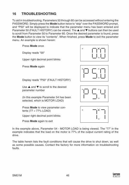
SM01M 46
16 TROUBLESHOOTING
Toadntroubleshootng,Parameters50through60canbeaccessedwthoutenterngthePASSWORD .SmplypresstheModebuttontwceto“skp”overthePASSWORDprompt,and“P50”wllbedsplayedtondcatethattheparametermenuhasbeenenteredandParameter50(FAULTHISTORY)canbevewed .TheandbuttonscanthenbeusedtoscrollfromParameter50toParameter60 .Oncethedesredparametersfound,presstheModebuttontovewts“contents” .Whenfinshed,pressModetoexttheparametermenu .Anexamplesshownheren:
PressModeonce
Upperrghtdecmalpontblnks
Dsplayreads"00"
PressModeagan
Dsplayreads"P50"(FAULTHISTORY)
Useandtoscrolltothedesredparameternumber
(InthsexampleParameter54hasbeenselected,whchsMOTORLOAD)
PressModetovewparametercon-tents(77=77%LOAD)
PressMode agantoext
Upperrghtdecmalpontblnks
Intheexampleabove,Parameter54-MOTORLOADsbengvewed .The“77”ntheexamplendcatesthattheloadonthemotors77%oftheoutputcurrentratngofthedrve .
Thetableherenlststhefaultcondtonsthatwllcausethedrvetoshutdown,aswellassomepossblecauses .Contactthefactoryformorenformatonontroubleshootngfaults .

47 SM01M
FAULT MESSAGES
FAULT DESCRIPTION & POSSIBLE CAUSES
AF High Temp. Fault: Ambient temperature is too high; Cooling fan has failed (if equipped).
CF Control Fault: A blank EPM, or an EPM with corrupted data has been installed. Per-form a factory reset using Parameter 48 - PROGRAM SELECTION.
cFIncompatibility Fault: An EPM with an incompatible parameter version has been in-stalled. Either remove the EPM or perform a factory reset (Parameter 48) to change the parameter version of the EPM to match the parameter version of the drive.
dF Dynamic Braking Fault: The drive has sensed that the dynamic braking resistors are overheating and shuts down to protect the resistors.
EF External Fault: One of the TB-13 terminals is set as an External Fault input and that terminal is open with respect to TB-11. Refer to Parameters 10, 11 and 12.
GF Data Fault: User data and OEM defaults in the EPM are corrupted.
HFHigh DC Bus Voltage Fault: Line voltage is too high; Deceleration rate is too fast; Over-hauling load. For fast deceleration or overhauling loads, dynamic braking may be required
JF Remote Keypad Fault: The communication link between the drive and the optional Remote Keypad has been lost. Check for proper wiring and/or noise.
LF Low DC Bus Voltage Fault: Line voltage is too low.
OFOutput Transistor Fault: Phase to phase or phase to ground short circuit on the output; Boost settings are too high; Acceleration rate is too fast; Failed output tran-sistor.
PF Current Overload Fault: VFD is undersized for the application; Mechanical problem with the driven equipment.
UFStart Fault: Start command was present when the drive was powered up. Must wait 2 seconds after power-up to apply Start command if START METHOD is set to NORMAL.
F1 EPM Fault: The EPM is missing or damaged.
FC, F2 - F9,
FoInternal Faults: The control board has sensed a problem - consult factory.
Toclearafault,ssueaSTOPcommandonthetermnalstrp .Thefaultwllonlyclearfthecondtonthatcausedthefaulthaspassed .Forexample,fthedrvetrpsonaLOWDCBUSVOLTAGEFAULT(LF)duetolownputvoltage,thefaultcannotbecleareduntlthenputvoltagereturnstoanormallevel .
Ifthedrvesprogrammedtoautomatcallyrestartafterafault(seeParameter03),thedrvewllattempttorestartthreetmesafterafault(thedrvewllnotrestartafterCF,cF,GF,FC,F1,F2-F9,orFofaults) .Ifallthreerestartattemptsareunsuccessful,thedrvewlltrpntoFAULTLOCKOUT(LC),whchrequresamanualresetasdescrbedabove .

SM01M 48
17 SCL/SCM DISPLAY MESSAGES
ThefollowngparagraphsdescrbethevarousdsplaysandmessagesthatcanappearontheSCL/SCMdrve .
17.1 Speed Display
IfthedrvesnaSTOPstate(ndcatedby"---"onthedsplay),andthecommandedspeedschanged,thedsplaywllshowthecommandedspeed,andtheupperleftdecmalpontwllturnonsold .Aboutfivesecondsafterachangesmade,thedsplaywllbegntoalternatebetweenthecommandedspeedvalueandthe"---"dsplay .IftheModebuttonspressed,thedsplaywllstopalternatngandshowthe"---"dsplayonly .
WhenthedrvesgvenaSTARTcommand,thedsplayedspeedwllstartncreasngasthedrveacceleratesuptothecommandedspeed .Ifthecommandedspeedschangedwhlethedrvesrunnng,thedsplaywllshowthecommandedspeedratherthantheactualspeed,untltheactualspeedreachesthecommandedspeed .
Ifthecommandedspeedschangedfasterthanthedrvecanaccelerateordecelerate,the upper left decmal pont wll blnk to ndcate that the the drve s acceleratng ordeceleratngtothenewspeed .Oncetheactualspeedreachesthecommandedspeed,theupperleftdecmalpontwllturnonsoldfor5secondsandthenturnofftondcatethatthecommandedspeedhasbeenreached,andthatthedsplaysnowshowngtheactualspeed .
17.2 Changing the Speed Reference Source
Whenthespeedsourceschangedwhlethedrvesrunnng,thedsplaywllflashthemessageforthenewspeedsourcetondcatethatthenewspeedsourcesactve .Also,fthedrvesbengcontrolledfromaspeedsourceotherthantheandbuttons(0-10VDC,4-20mA,etc),andoneoftheorbuttonsspressed,thedsplaywllflashthepresentspeedsourcemessagetondcatethattheandbuttonsarenvald .
Example 1:Thedrvesrunnngandthepresentspeedsourcesthekeypad .TB-13Asprogrammedtoselecta4-20mAsgnalasthespeedsource .WhenTB-13AsclosedtoTB-11,thedsplaywllflash“EI”tondcatethatthespeedsourcehaschangedtothe4-20mAsgnal .IfthecontactbetweenTB-13AandTB-11sopened,thedsplaywllflash“CP”tondcatethatthespeedsourcehaschangedbacktotheandbuttons .
Example 2:Thespeedsourcesa0-10VDCsgnal .Iftheorbuttonspushed,thedsplaywllflash“EU”tondcatethatthepresentspeedsourcesthe0-10VDCsgnalandthattheandbuttonsarenvald .

49 SM01M
Refertothefollowngtableforthepossblespeedreferencesourcedsplays:
SPEED SOURCE DISPLAYSDISPLAY DESCRIPTION
CP CONTROL PAD: Speed is set using the and buttons on the front of the drive.
EI EXTERNAL CURRENT: Speed is controlled by a 4-20 mA signal wired to TB-25 and TB-2
EU EXTERNAL VOLTAGE: Speed is controlled by a 0-10 VDC signal wired to TB-5 and TB-2.
JG JOG: The drive is in Jog mode, and the speed is set by Preset Speed #2 (Parameter 32).
OP MOP (Motor Operated Pot): Contacts wired to TB-13B and TB-13E are used to increase and decrease the drive speed.
Pr1 - Pr7 PRESET SPEEDS #1-7: Speed is set by the indicated Preset Speed (Parameters 31-37).
NOTEThespeedsourcedsplayswllflashwhenthespeedreferencesourceschangedwhle the drve s runnng to ndcate that the new speed reference source sactve
17.3 Status and Warning Messages
STATUS AND WARNING MESSAGES
DISPLAY DESCRIPTIONbr DC BRAKING: The DC braking circuit is activated.
cE“cE” will be displayed if an EPM with a different parameter version is installed and then an attempt is made to change parameter settings without performing the TRANSLATE function. Refer to PROGRAM SELECTION (Parameter 48).
CL
CURRENT LIMIT: The output current has exceeded the CURRENT LIMIT setting (Parameter 25) and the drive is reducing the output frequency to reduce the output current. If the drive remains in CURRENT LIMIT for too long, it can trip into a CURRENT OVERLOAD fault (PF).
Er ERROR: Invalid data has been entered or an invalid command was attempted.
GE “GE” will be displayed if an attempt is made to change the OEM default settings when the drive is operating in the OEM mode (refer to Parameter 48).
GFIf “GF” is displayed when a RESET OEM is attempted, it indicates that the OEM defaults in the EPM are corrupted. If “GF” is displayed upon power-up, it indicates that the OEM defaults and the user settings in the EPM are corrupted. Refer to Section 13.2.
LC FAULT LOCKOUT: The drive has failed three restart attempts and now requires a manual reset.
SE SERIAL: The optional remote keypad is active as the user interface instead of the buttons on front of the drive. Refer to Parameter 14 (CONTROL).
SP START PENDING: “SP” blinks during the interval between restart attempts.
DECEL OVERRIDE (both upper decimal points blinking): The drive has stopped decelerating to avoid tripping into an HF fault due to regenerative energy from the motor.

Notes

Notes

Notes

Notes

Notes


AC Technology Corporation630 Douglas Street • Uxbridge, MA 01569 • USASales: 800 217-9100 • Service: 508 278-9100
www.lenze-actech.com
SM01M