Science Instruments, Observatories, and Sensor Systems
115
NASA Technology Roadmaps TA 8: Science Instruments, Observatories, and Sensor Systems July 2015
Transcript of Science Instruments, Observatories, and Sensor Systems
NASA Technology RoadmapsTA 8: Science Instruments, Observatories, and Sensor Systems
July 2015
2015 NASA Technology RoadmapsTA 8: Science Instruments, Observatories, and Sensor Systems
TA 8 - 2
July 2015
ForewordNASA is leading the way with a balanced program of space exploration, aeronautics, and science research. Success in executing NASA’s ambitious aeronautics activities and space missions requires solutions to difficult technical challenges that build on proven capabilities and require the development of new capabilities. These new capabilities arise from the development of novel cutting-edge technologies. The promising new technology candidates that will help NASA achieve our extraordinary missions are identified in our Technology Roadmaps. The roadmaps are a set of documents that consider a wide range of needed technology candidates and development pathways for the next 20 years. The roadmaps are a foundational element of the Strategic Technology Investment Plan (STIP), an actionable plan that lays out the strategy for developing those technologies essential to the pursuit of NASA’s mission and achievement of National goals. The STIP provides prioritization of the technology candidates within the roadmaps and guiding principles for technology investment. The recommendations provided by the National Research Council heavily influence NASA’s technology prioritization. NASA’s technology investments are tracked and analyzed in TechPort, a web-based software system that serves as NASA’s integrated technology data source and decision support tool. Together, the roadmaps, the STIP, and TechPort provide NASA the ability to manage the technology portfolio in a new way, aligning mission directorate technology investments to minimize duplication, and lower cost while providing critical capabilities that support missions, commercial industry, and longer-term National needs.The 2015 NASA Technology Roadmaps are comprised of 16 sections: The Introduction, Crosscutting Technologies, and Index; and 15 distinct Technology Area (TA) roadmaps. Crosscutting technology areas, such as, but not limited to, avionics, autonomy, information technology, radiation, and space weather span across multiple sections. The introduction provides a description of the crosscutting technologies, and a list of the technology candidates in each section.
2015 NASA Technology RoadmapsTA 8: Science Instruments, Observatories, and Sensor Systems
TA 8 - 3
July 2015
Table of ContentsExecutive Summary . . . . . . . . . . . . . . . . . . . . . . . . . . . . . . . . . . . . . . . . . . . . . . . . . . . . . . . . . . . 8-4
Introduction . . . . . . . . . . . . . . . . . . . . . . . . . . . . . . . . . 8-98.1 Remote Sensing Instruments and Sensors. . . . . . . . . . . . . . . . . . . . . . . . . . . . . . . . . . . . . . 8-98.2 Observatories . . . . . . . . . . . . . . . . . . . . . . . . . . . . . . . . . . . . . . . . . . . . . . . . . . . . . . . . . . . . 8-98.3 In-Situ Instruments and Sensors . . . . . . . . . . . . . . . . . . . . . . . . . . . . . . . . . . . . . . . . . . . . . 8-11
TA 8 .1: Remote Sensing Instruments and Sensors . . . . . . . . . . . . . . . . 8-12
TA 8 .2: Observatories . . . . . . . . . . . . . . . . . . . . . . . . . . . . . . . . . . . . . . 8-21Sub-Goals . . . . . . . . . . . . . . . . . . . . . . . . . . . . . . . . . . . . . . . . . . . . . . . . . . . . . . . . . . . . . . . . 8-21
TA 8 .3: In-Situ Instruments and Sensors . . . . . . . . . . . . . . . . . . . . . . . . . . . . . . . . . . . . . . . . . 8-27
Appendix . . . . . . . . . . . . . . . . . . . . . . . . . . . . . . . . . . . . . . . . . . . . . . . . . . . . . . . . . . . . . . . . . . . 8-33Acronyms . . . . . . . . . . . . . . . . . . . . . . . . . . . . . . . . . . . . . . . . . . . . . . . . . . . . . . . . . . . . . . . . . 8-33Abbreviations and Units . . . . . . . . . . . . . . . . . . . . . . . . . . . . . . . . . . . . . . . . . . . . . . . . . . . . . . 8-36Contributors . . . . . . . . . . . . . . . . . . . . . . . . . . . . . . . . . . . . . . . . . . . . . . . . . . . . . . . . . . . . . . . . 8-38Technology Candidate Snapshots. . . . . . . . . . . . . . . . . . . . . . . . . . . . . . . . . . . . . . . . . . . . . . . 8-39
2015 NASA Technology RoadmapsTA 8: Science Instruments, Observatories, and Sensor Systems
TA 8 - 4
July 2015
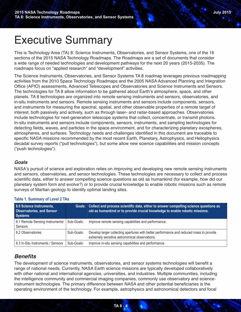
Executive SummaryThis is Technology Area (TA) 8: Science Instruments, Observatories, and Sensor Systems, one of the 16 sections of the 2015 NASA Technology Roadmaps. The Roadmaps are a set of documents that consider a wide range of needed technologies and development pathways for the next 20 years (2015-2035). The roadmaps focus on “applied research” and “development” activities. The Science Instruments, Observatories, and Sensor Systems TA 8 roadmap leverages previous roadmapping activities from the 2010 Space Technology Roadmaps and the 2005 NASA Advanced Planning and Integration Office (APIO) assessments, Advanced Telescopes and Observatories and Science Instruments and Sensors. The technologies for TA 8 allow information to be gathered about Earth’s atmosphere, space, and other planets. TA 8 technologies are organized into remote sensing instruments and sensors, observatories, and in-situ instruments and sensors. Remote sensing instruments and sensors include components, sensors, and instruments for measuring the spectral, spatial, and other observable properties of a remote target of interest, both passively and actively, such as through laser- and radar-based approaches. Observatories include technologies for next-generation telescope systems that collect, concentrate, or transmit photons. In-situ instruments and sensors include components, sensors, instruments, and sampling technologies for detecting fields, waves, and particles in the space environment, and for characterizing planetary exospheres, atmospheres, and surfaces. Technology needs and challenges identified in this document are traceable to specific NASA missions recommended by the most recent Earth, Planetary, Astrophysics, and Heliophysics decadal survey reports (“pull technologies”), but some allow new science capabilities and mission concepts (“push technologies”).
GoalsNASA’s pursuit of science and exploration relies on improving and developing new remote sensing instruments and sensors, observatories, and sensor technologies. These technologies are necessary to collect and process scientific data, either to answer compelling science questions as old as humankind (for example, how did our planetary system form and evolve?) or to provide crucial knowledge to enable robotic missions such as remote surveys of Martian geology to identify optimal landing sites.
Table 1. Summary of Level 2 TAs8.0 Science Instruments, Observatories, and Sensor Systems
Goals: Collect and process scientific data, either to answer compelling science questions as old as humankind or to provide crucial knowledge to enable robotic missions.
8.1 Remote Sensing Instruments/Sensors
Sub-Goals: Improve remote sensing capabilities and performance.
8.2 Observatories Sub-Goals: Develop larger collecting apertures with better performance and reduced mass to provide extremely sensitive astronomical observations.
8.3 In-Situ Instruments / Sensors Sub-Goals: Improve in-situ sensing capabilities and performance.
BenefitsThe development of science instruments, observatories, and sensor systems technologies will benefit a range of national needs. Currently, NASA Earth science missions are typically developed collaboratively with other national and international agencies, universities, and industries. Multiple communities, including the intelligence community and commercial imaging companies, commonly use observatory and science-instrument technologies. The primary difference between NASA and other potential beneficiaries is the operating environment of the technology. For example, astrophysics and astronomical detectors and focal
2015 NASA Technology RoadmapsTA 8: Science Instruments, Observatories, and Sensor Systems
TA 8 - 5
July 2015
planes have similar low-noise sensitivity requirements but different operating environments, such as radiation hardness. A similar comparison can be made between planetary or heliophysics in-situ sensors and those used on the battlefield, in a hospital, at port and border checkpoints, or in the transportation area. X-ray mirror technology can be applied to commercial X-ray microscopes, X-ray lithography, or synchrotron optics. Space microwave, radar, or terahertz (THz) imaging systems can be applied to numerous government and industrial applications such as airport security screening and smoke stack plume monitoring; light detection and ranging (LIDAR) and differential absorption LIDAR (DIAL) remote sensing technology have applications ranging from three dimensional (3D) surface topography and weather prediction to smoke stack pollution compliance.
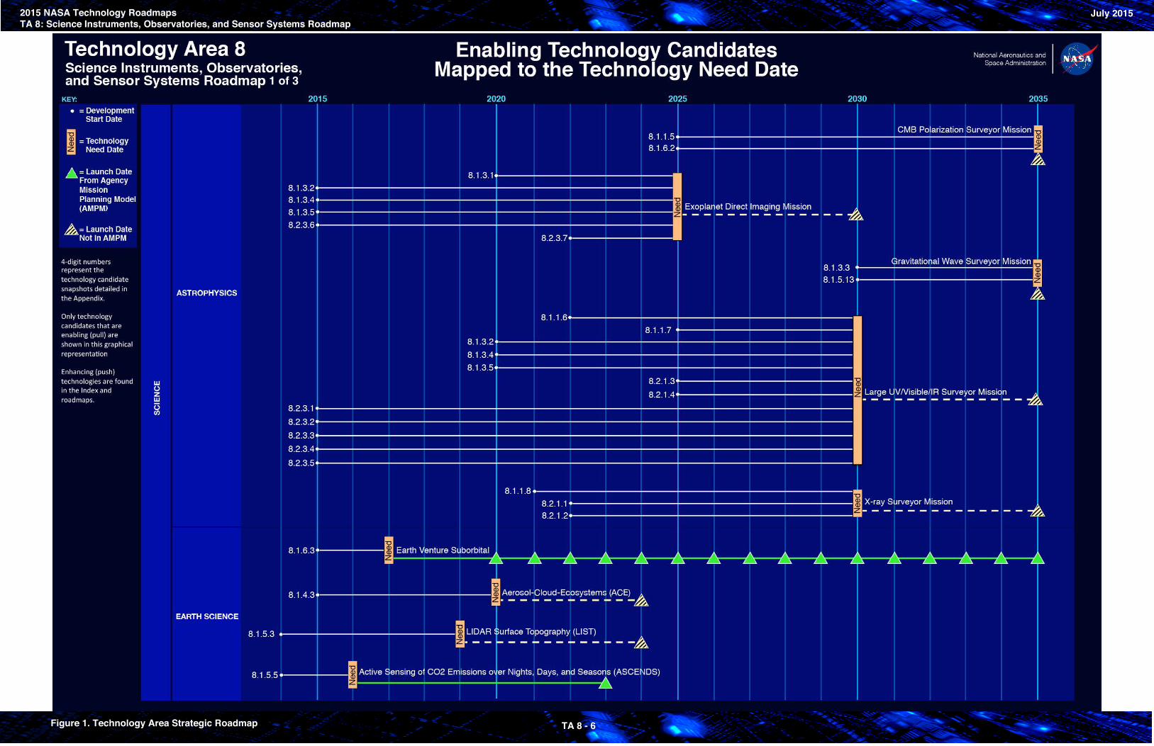
1 of 3
2015 NASA Technology RoadmapsTA 8: Science Instruments, Observatories, and Sensor Systems Roadmap
July 2015
Figure 1. Technology Area Strategic Roadmap TA 8 - 6
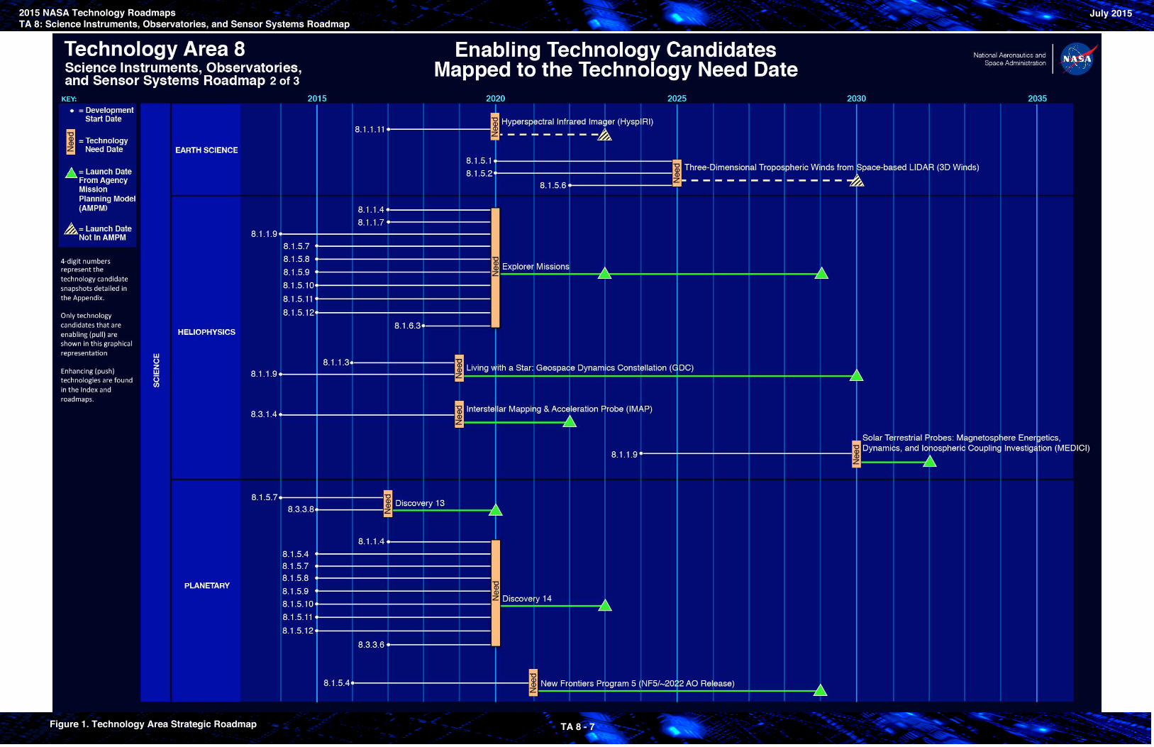
2 of 3
2015 NASA Technology RoadmapsTA 8: Science Instruments, Observatories, and Sensor Systems Roadmap
July 2015
Figure 1. Technology Area Strategic Roadmap TA 8 - 7
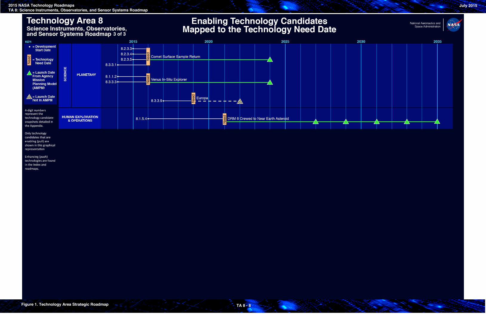
3 of 3
2015 NASA Technology RoadmapsTA 8: Science Instruments, Observatories, and Sensor Systems Roadmap
July 2015
Figure 1. Technology Area Strategic Roadmap TA 8 - 8

2015 NASA Technology RoadmapsTA 8: Science Instruments, Observatories, and Sensor Systems
TA 8 - 9
July 2015
IntroductionThe Science Instruments, Observatories, and Sensor Systems technology area (TA) encompasses technologies to collect disparate types of data from Earth and space. These technologies are either identified to satisfy a particular mission need (“pull technologies”) or to develop new measurement techniques that may lead to new scientific discoveries (“push technologies”). This TA is broken into three sub-areas: remote-sensing instruments and sensors; observatories; and in-situ instruments and sensors. These technologies are applicable to missions from very small to large.Remote sensing instruments and sensors includes components, sensors, and instruments sensitive to electromagnetic radiation, particles, electromagnetic fields, both direct and alternating current, acoustic energy, seismic energy, or whatever physical phenomenology the science requires. Observatories include technologies that collect, concentrate, or transmit photons. In-situ instruments and sensors include components, sensors, and instruments sensitive to fields, waves, and particles that are able to perform in-situ characterization of planetary samples or phenomena.The complete Technology Area Breakdown Structure (TABS) for TA 8 is shown in Figure 2.
8.1 Remote Sensing Instruments and SensorsRemote sensing instruments and sensors include components, sensors, and instruments sensitive to electromagnetic radiation, particles (charged, neutral, dust), electromagnetic fields, both direct current (DC) and alternating current (AC), acoustic energy, seismic energy, or whatever physical phenomenology the science requires. These technologies can be grouped into the following general categories:
•
•
•
•
• •
8 .1 .1 Detectors and Focal Planes: Improve sensitivity and operating temperature of single-element and large-array devices.8 .1 .2 Electronic: Radiation-hardened, extreme environment capable, and data processing electronics with reduced volume, mass, and power.8 .1 .3 Optical Components: High-throughput optics with large fields of view, high stability, spectral resolution, and uniformity at many different temperatures.8 .1 .4 Microwave, Millimeter-, and Submillimeter-Waves: Transmitters and receivers: low-noise amplifier technologies, with reliable low-power high-speed digital- and mixed-signal processing electronics, and algorithms.8 .1 .5 Lasers: Reliable, highly stable, efficient, radiation hardened, and long lifetime (> 5 years).8 .1 .6 Cryogenic/Thermal: Active technologies used to cool instruments and focal planes, sensors, and large optical systems.
8.2 ObservatoriesObservatory technologies are necessary to design, manufacture, test, and operate space telescopes and antennas, which collect, concentrate, or transmit photons. Observatory technologies enable or enhance large-aperture monolithic and segmented single apertures as well as structurally connected or free-flying sparse and interferometric apertures. Applications span the electromagnetic spectrum. Based on the needs of planned and potential future NASA missions, it is possible to define three specific enabling observatory technologies:
2015 NASA Technology RoadmapsTA 8: Science Instruments, Observatories, and Sensor Systems
TA 8 - 10
July 2015
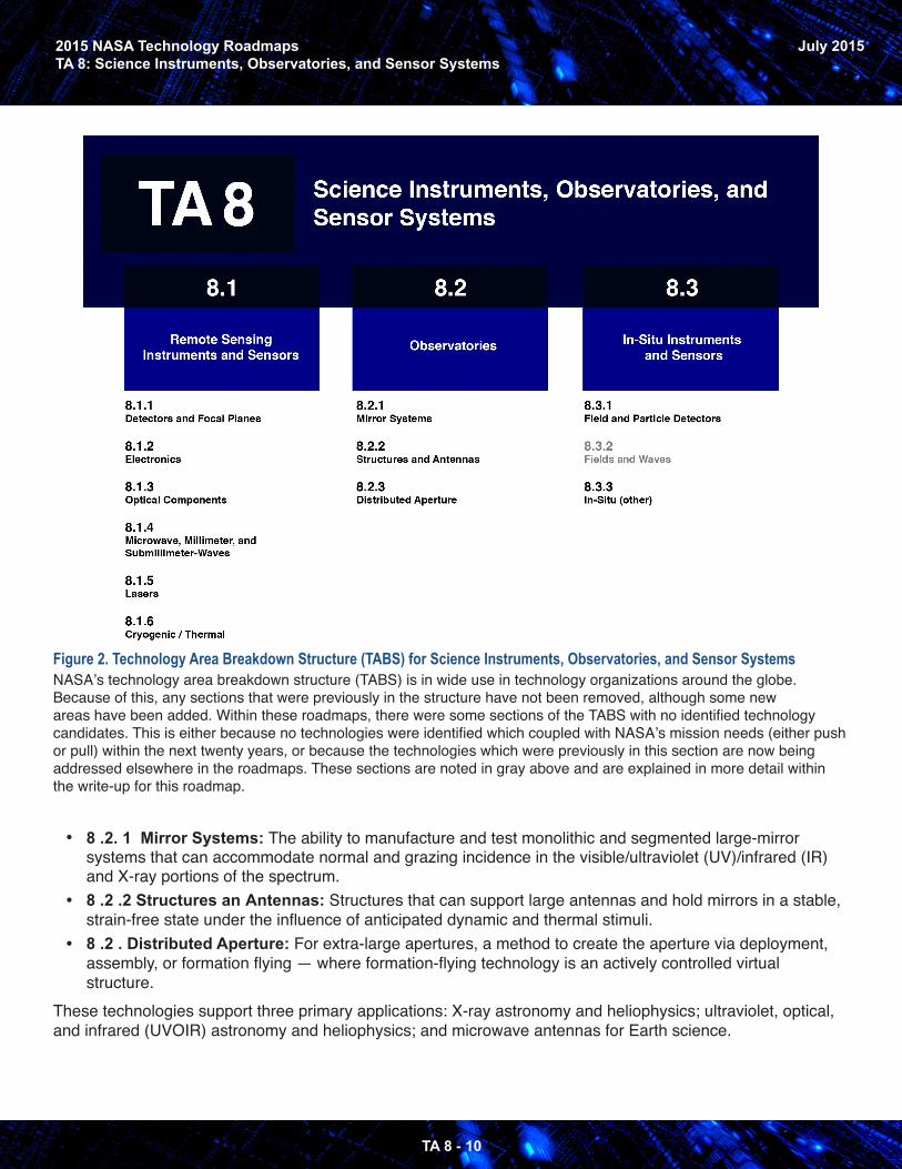
Figure 2. Technology Area Breakdown Structure (TABS) for Science Instruments, Observatories, and Sensor Systems
•
•
•
NASA’s technology area breakdown structure (TABS) is in wide use in technology organizations around the globe. Because of this, any sections that were previously in the structure have not been removed, although some new areas have been added. Within these roadmaps, there were some sections of the TABS with no identified technology candidates. This is either because no technologies were identified which coupled with NASA’s mission needs (either push or pull) within the next twenty years, or because the technologies which were previously in this section are now being addressed elsewhere in the roadmaps. These sections are noted in gray above and are explained in more detail within the write-up for this roadmap.
8 .2. 1 Mirror Systems: The ability to manufacture and test monolithic and segmented large-mirror systems that can accommodate normal and grazing incidence in the visible/ultraviolet (UV)/infrared (IR) and X-ray portions of the spectrum.8 .2 .2 Structures an Antennas: Structures that can support large antennas and hold mirrors in a stable, strain-free state under the influence of anticipated dynamic and thermal stimuli.8 .2 . Distributed Aperture: For extra-large apertures, a method to create the aperture via deployment, assembly, or formation flying — where formation-flying technology is an actively controlled virtual structure.
These technologies support three primary applications: X-ray astronomy and heliophysics; ultraviolet, optical, and infrared (UVOIR) astronomy and heliophysics; and microwave antennas for Earth science.
2015 NASA Technology RoadmapsTA 8: Science Instruments, Observatories, and Sensor Systems
TA 8 - 11
July 2015
8.3 In-Situ Instruments and SensorsIn-situ instruments and sensors include components, sensors, and instruments sensitive to fields and particles able to perform in-situ characterization of the space environment and planetary samples. In-situ instruments and sensors technologies enable or enhance a broad range of planned and potential missions in the next two decades. In-situ instruments and sensors support comet, Moon, and planetary missions. These technologies can be grouped into the following general categories:
•
•
8 .3 .1 Field and Particle Detectors: A variety of instruments aiming to characterize a large, spatially-rich, and temporally dynamic space environment spanning from Earth’s and planetary ionospheres and magnetospheres to the solar corona, the heliosphere or heliopause, and the local interstellar medium.
8 .3 .3 In-situ (other): In-situ sensor technologies (for chemical, mineralogical, organic, and in-situbiological samples) include sample handling, preparation, and containment; chemical and mineralanalysis; organic analysis; biological detection and characterization; and planetary protection. Thesetechnologies need to be applied in extreme temperatures, pressures, and environments.
• 8 .3 .2 Fields and Waves: Fields and waves sensors are addressed in section TA 8.3.1 Field andParticle Detectors, and TA 8.3.3 In-situ (other).
2015 NASA Technology RoadmapsTA 8: Science Instruments, Observatories, and Sensor Systems
TA 8 - 12
July 2015
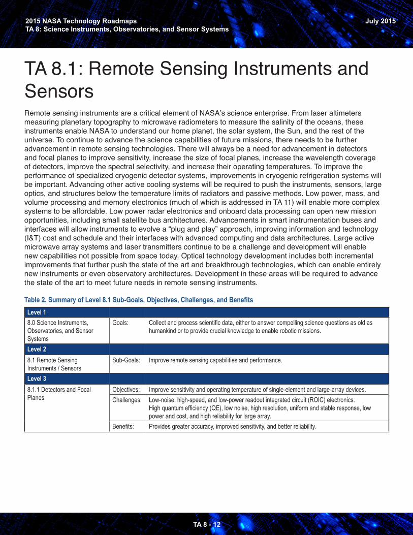
TA 8.1: Remote Sensing Instruments and Sensors Remote sensing instruments are a critical element of NASA’s science enterprise. From laser altimeters measuring planetary topography to microwave radiometers to measure the salinity of the oceans, these instruments enable NASA to understand our home planet, the solar system, the Sun, and the rest of the universe. To continue to advance the science capabilities of future missions, there needs to be further advancement in remote sensing technologies. There will always be a need for advancement in detectors and focal planes to improve sensitivity, increase the size of focal planes, increase the wavelength coverage of detectors, improve the spectral selectivity, and increase their operating temperatures. To improve the performance of specialized cryogenic detector systems, improvements in cryogenic refrigeration systems will be important. Advancing other active cooling systems will be required to push the instruments, sensors, large optics, and structures below the temperature limits of radiators and passive methods. Low power, mass, and volume processing and memory electronics (much of which is addressed in TA 11) will enable more complex systems to be affordable. Low power radar electronics and onboard data processing can open new mission opportunities, including small satellite bus architectures. Advancements in smart instrumentation buses and interfaces will allow instruments to evolve a “plug and play” approach, improving information and technology (I&T) cost and schedule and their interfaces with advanced computing and data architectures. Large active microwave array systems and laser transmitters continue to be a challenge and development will enable new capabilities not possible from space today. Optical technology development includes both incremental improvements that further push the state of the art and breakthrough technologies, which can enable entirely new instruments or even observatory architectures. Development in these areas will be required to advance the state of the art to meet future needs in remote sensing instruments.
Table 2. Summary of Level 8.1 Sub-Goals, Objectives, Challenges, and BenefitsLevel 18.0 Science Instruments, Observatories, and Sensor Systems
Goals: Collect and process scientific data, either to answer compelling science questions as old as humankind or to provide crucial knowledge to enable robotic missions.
Level 28.1 Remote Sensing Instruments / Sensors
Sub-Goals: Improve remote sensing capabilities and performance.
Level 38.1.1 Detectors and Focal Planes
Objectives: Improve sensitivity and operating temperature of single-element and large-array devices.Challenges: Low-noise, high-speed, and low-power readout integrated circuit (ROIC) electronics.
High quantum efficiency (QE), low noise, high resolution, uniform and stable response, low power and cost, and high reliability for large array.
Benefits: Provides greater accuracy, improved sensitivity, and better reliability.
2015 NASA Technology RoadmapsTA 8: Science Instruments, Observatories, and Sensor Systems
TA 8 - 13
July 2015
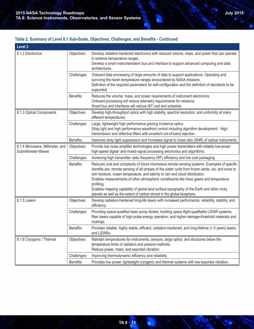
Level 38.1.2 Electronics Objectives: Develop radiation-hardened electronics with reduced volume, mass, and power that can operate
in extreme temperature ranges.Develop a smart instrumentation bus and interface to support advanced computing and data architectures.
Challenges: Onboard data processing of large amounts of data to support applications. Operating and surviving the harsh temperature ranges encountered by NASA missions.Definition of the required parameters for self-configuration and the definition of standards to be supported.
Benefits: Reduces the volume, mass, and power requirements of instrument electronics.Onboard processing will reduce telemetry requirements for missions.Smart bus and interfaces will reduce I&T cost and schedule.
8.1.3 Optical Components Objectives: Develop high-throughput optics with high stability, spectral resolution, and uniformity at many different temperatures.
Challenges: Large, lightweight high performance grazing incidence optics. Stray light and high performance wavefront control including algorithm development. High transmission and reflective filters with excellent out-of-band rejection.
Benefits: Improves stray light suppression and increases signal to noise ratio (SNR) of optical instruments.8.1.4 Microwave, Millimeter, and Submillimeter-Waves
Objectives: Provide low noise amplifier technologies and high power transmitters with reliable low-power high-speed digital- and mixed-signal processing electronics and algorithms.
Challenges: Achieving high transmitter radio frequency (RF) efficiency and low cost packaging.Benefits: Reduces cost and complexity of future microwave remote sensing systems. Examples of specific
benefits are: remote sensing of all phases of the water cycle from frozen lands, ice, and snow to soil moisture, ocean temperature, and salinity to rain and cloud distribution. Enables measurements of other atmospheric constituents like trace gases and temperature profiling. Enables mapping capability of global land surface topography of the Earth and other rocky planets as well as the extent of carbon stored in the global biosphere.
8.1.5 Lasers Objectives: Develop radiation-hardened long-life lasers with increased performance, reliability, stability, and efficiency.
Challenges: Providing space-qualified laser pump diodes; building space flight-qualifiable LIDAR systems; fiber lasers capable of high-pulse energy operation; and higher-damage-threshold materials and coatings.
Benefits: Provides reliable, highly stable, efficient, radiation-hardened, and long-lifetime (> 5 years) lasers and LIDARs.
8.1.6 Cryogenic / Thermal Objectives: Maintain temperatures for instruments, sensors, large optics, and structures below the temperature limits of radiators and passive methods.Reduce power, mass, and exported vibration.
Challenges: Improving thermodynamic efficiency and reliability.Benefits: Provides low power, lightweight cryogenic and thermal systems with low exported vibration.
Table 2. Summary of Level 8.1 Sub-Goals, Objectives, Challenges, and Benefits - Continued
2015 NASA Technology RoadmapsTA 8: Science Instruments, Observatories, and Sensor Systems
TA 8 - 14
July 2015
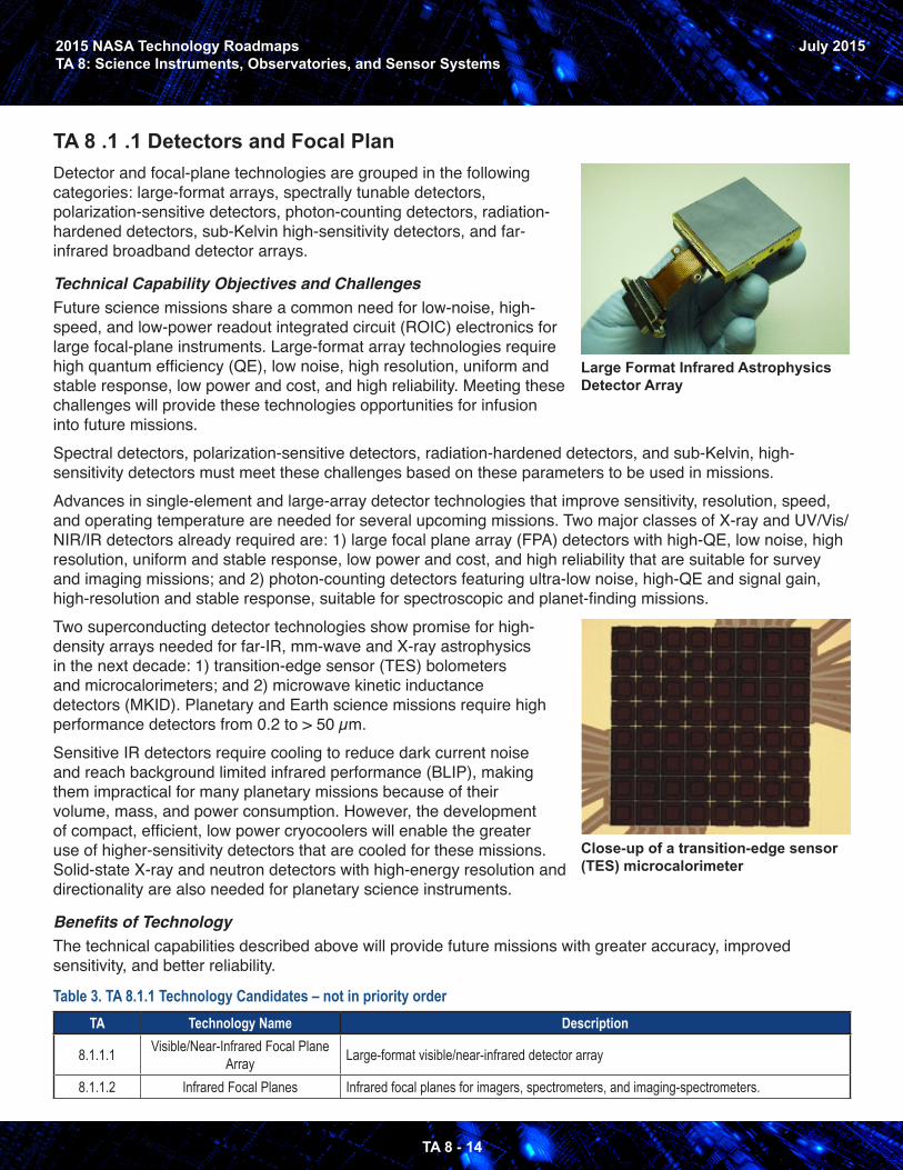
TA 8 .1 .1 Detectors and Focal PlanDetector and focal-plane technologies are grouped in the following categories: large-format arrays, spectrally tunable detectors, polarization-sensitive detectors, photon-counting detectors, radiation-hardened detectors, sub-Kelvin high-sensitivity detectors, and far-infrared broadband detector arrays.
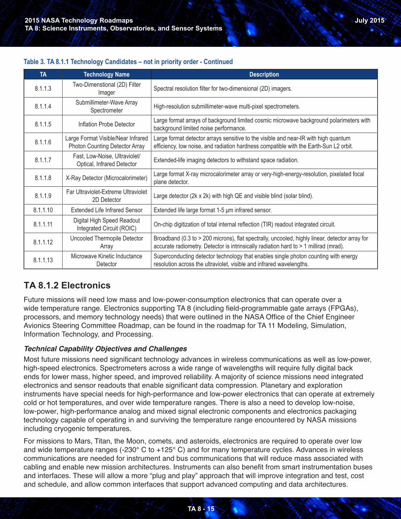
Technical Capability Objectives and ChallengesFuture science missions share a common need for low-noise, high-speed, and low-power readout integrated circuit (ROIC) electronics for large focal-plane instruments. Large-format array technologies require high quantum efficiency (QE), low noise, high resolution, uniform and stable response, low power and cost, and high reliability. Meeting these challenges will provide these technologies opportunities for infusion into future missions.Spectral detectors, polarization-sensitive detectors, radiation-hardened detectors, and sub-Kelvin, high-sensitivity detectors must meet these challenges based on these parameters to be used in missions.Advances in single-element and large-array detector technologies that improve sensitivity, resolution, speed, and operating temperature are needed for several upcoming missions. Two major classes of X-ray and UV/Vis/NIR/IR detectors already required are: 1) large focal plane array (FPA) detectors with high-QE, low noise, high resolution, uniform and stable response, low power and cost, and high reliability that are suitable for survey and imaging missions; and 2) photon-counting detectors featuring ultra-low noise, high-QE and signal gain, high-resolution and stable response, suitable for spectroscopic and planet-finding missions.Two superconducting detector technologies show promise for high-density arrays needed for far-IR, mm-wave and X-ray astrophysics in the next decade: 1) transition-edge sensor (TES) bolometers and microcalorimeters; and 2) microwave kinetic inductance detectors (MKID). Planetary and Earth science missions require high performance detectors from 0.2 to > 50 µm.Sensitive IR detectors require cooling to reduce dark current noise and reach background limited infrared performance (BLIP), making them impractical for many planetary missions because of their volume, mass, and power consumption. However, the development of compact, efficient, low power cryocoolers will enable the greater use of higher-sensitivity detectors that are cooled for these missions. Solid-state X-ray and neutron detectors with high-energy resolution and directionality are also needed for planetary science instruments.
Benefits of TechnologyThe technical capabilities described above will provide future missions with greater accuracy, improved sensitivity, and better reliability.
Close-up of a transition-edge sensor (TES) microcalorimeter
Table 3. TA 8.1.1 Technology Candidates – not in priority orderTA Technology Name Description
8.1.1.1 Visible/Near-Infrared Focal Plane Array Large-format visible/near-infrared detector array
8.1.1.2 Infrared Focal Planes Infrared focal planes for imagers, spectrometers, and imaging-spectrometers.
Large Format Infrared Astrophysics Detector Array
2015 NASA Technology RoadmapsTA 8: Science Instruments, Observatories, and Sensor Systems
TA 8 - 15
July 2015
Table 3. TA 8.1.1 Technology Candidates – not in priority order - ContinuedTA Technology Name Description
8.1.1.3 Two-Dimenstional (2D) Filter Imager Spectral resolution filter for two-dimensional (2D) imagers.
8.1.1.4 Submillimeter-Wave Array Spectrometer High-resolution submillimeter-wave multi-pixel spectrometers.
8.1.1.5 Inflation Probe Detector Large format arrays of background limited cosmic microwave background polarimeters with background limited noise performance.
8.1.1.6 Large Format Visible/Near Infrared Photon Counting Detector Array
Large format detector arrays sensitive to the visible and near-IR with high quantum efficiency, low noise, and radiation hardness compatible with the Earth-Sun L2 orbit.
8.1.1.7 Fast, Low-Noise, Ultraviolet/Optical, Infrared Detector Extended-life imaging detectors to withstand space radiation.
8.1.1.8 X-Ray Detector (Microcalorimeter) Large format X-ray microcalorimeter array or very-high-energy-resolution, pixelated focal plane detector.
8.1.1.9 Far Ultraviolet-Extreme Ultraviolet 2D Detector Large detector (2k x 2k) with high QE and visible blind (solar blind).
8.1.1.10 Extended Life Infrared Sensor Extended life large format 1-5 μm infrared sensor.
8.1.1.11 Digital High Speed Readout Integrated Circuit (ROIC) On-chip digitization of total internal reflection (TIR) readout integrated circuit.
8.1.1.12 Uncooled Thermopile Detector Array
Broadband (0.3 to > 200 microns), flat spectrally, uncooled, highly linear, detector array for accurate radiometry. Detector is intrinsically radiation hard to > 1 millirad (mrad).
8.1.1.13 Microwave Kinetic Inductance Detector
Superconducting detector technology that enables single photon counting with energy resolution across the ultraviolet, visible and infrared wavelengths.
TA 8.1.2 ElectronicsFuture missions will need low mass and low-power-consumption electronics that can operate over a wide temperature range. Electronics supporting TA 8 (including field-programmable gate arrays (FPGAs), processors, and memory technology needs) that were outlined in the NASA Office of the Chief Engineer Avionics Steering Committee Roadmap, can be found in the roadmap for TA 11 Modeling, Simulation, Information Technology, and Processing.
Technical Capability Objectives and ChallengesMost future missions need significant technology advances in wireless communications as well as low-power, high-speed electronics. Spectrometers across a wide range of wavelengths will require fully digital back ends for lower mass, higher speed, and improved reliability. A majority of science missions need integrated electronics and sensor readouts that enable significant data compression. Planetary and exploration instruments have special needs for high-performance and low-power electronics that can operate at extremely cold or hot temperatures, and over wide temperature ranges. There is also a need to develop low-noise, low-power, high-performance analog and mixed signal electronic components and electronics packaging technology capable of operating in and surviving the temperature range encountered by NASA missions including cryogenic temperatures. For missions to Mars, Titan, the Moon, comets, and asteroids, electronics are required to operate over low and wide temperature ranges (-230° C to +125° C) and for many temperature cycles. Advances in wireless communications are needed for instrument and bus communications that will reduce mass associated with cabling and enable new mission architectures. Instruments can also benefit from smart instrumentation buses and interfaces. These will allow a more “plug and play” approach that will improve integration and test, cost and schedule, and allow common interfaces that support advanced computing and data architectures.
2015 NASA Technology RoadmapsTA 8: Science Instruments, Observatories, and Sensor Systems
TA 8 - 16
July 2015
Benefits of TechnologyAcross all disciplines, reducing the volume, mass, and power requirements of instrument electronics is essential to maximizing the science return for future missions.
Table 4. TA 8.1.2 Technology Candidates – not in priority orderTA Technology Name Description
8.1.2.1 Miniaturized, Low-Power Radar Electronics Provide miniaturized and low-power radar electronics.
8.1.2.2 Onboard Radar Data Processing Advanced onboard processing capabilities to handle larger volumes of radar data.
8.1.2.3 Smart Instrumentation Bus and Interface
Instruments need to evolve to a more “plug and play” approach to improve I&T cost and schedule, and to better interface with advanced computing and data architectures.
8.1.2.4
Highly Integrated Extreme Environment Capable High-
Performance Low-Power Instrument Electronics
High-performance and low-power instrument electronics that can operate at extremely cold or hot temperatures, and over wide temperature ranges.
TA 8.1.3 Optical ComponentsOptical component technologies are grouped in the following categories: ultraviolet imaging, wide field of view imaging for near-Earth asteroids, and instruments for quantum interferometry. Improvements in optical components complement improvements in detectors. Technical Capability Objectives and ChallengesOptical technology development includes both incremental improvements that further push the state of the art and breakthrough technologies that can enable entirely new instrument or observatory architectures. There are a wide variety of instrument types optimized for each science need and only some of the technologies are described here. Competitive technology opportunities best identify new ideas that are often based on improving optical performance. The technology developments then lead to instrument incubator and test-bed activities to support missions. Advanced spectrometer and instrument subsystems can enable new measurement capabilities. These subsystems can be used in smaller, midsized, or larger instruments.Benefits of TechnologyAdvances including optical material development may enable new instrument and sensor measurement capabilities. These advances include recent breakthroughs in nano-fabrication and field-controllable devices that will eliminate current mechanical operation approaches, decreasing risk of mechanical failure. High-throughput optics with large fields of view, high stability, spectral resolution, and uniformity at many different temperatures will enable and enhance future missions.
Table 5. TA 8.1.3 Technology Candidates – not in priority orderTA Technology Name Description
8.1.3.1 Coronagraph Coronagraphs and nulling interferometers suppress starlight in the focal plane by blocking portions of the beam as well as modifying its phase and amplitude.Starshades are deployed structures that block starlight to form a dark shadow around a distant telescope, enabling direct detection and characterization of extrasolar planets as small as Exo-Earths.
8.1.3.2 Occulter
8.1.3.3 Carbon Nanotube Absorbers and Coatings and Occulting Masks
Carbon nanotube “forests” used for their broadband, high absorption of electromagnetic radiation.
2015 NASA Technology RoadmapsTA 8: Science Instruments, Observatories, and Sensor Systems
TA 8 - 17
July 2015
Table 5. TA 8.1.3 Technology Candidates – not in priority order - Continued
TA Technology Name Description
8.1.3.4 Wavefront Control of Large Optical Space Telescope
Wavefront control consists of actuators for implementing corrections to the figure and alignment of the optics and algorithms and software for determining the corrections to be made based on the measurements.
8.1.3.5 Wavefront Sensing of Large Optical Space Telescope
Wavefront sensing for large telescopes is typically performed by either image-based approaches that use the captured image to sense the wavefront error, or metrology-based approaches that use sensors to measure the shape of the mirrors.
8.1.3.6 Transmission FilterNarrow short wavelength band filters (extreme to far ultraviolet) with high transmission that enable high signal-to-noise ratio in order to observe weak signals in the presence of bright signals found in heliophysics observations.
8.1.3.7 Reflective Filter Narrow-band filters with high reflectivity that enable high signal-to-noise measurements.
8.1.3.8 Wide Field of View Reflective Imager
Allow the formation of an image on a flat detector to image near-Earth space from highly elliptical orbits
8.1.3.9 Quantum Optical Interferometry Interferometry with sensitivity significantly better than the quantum shot noise limit.
TA 8.1.4 Microwave, Millimeter-, and Submillimeter WavesMicrowave and radio transmitter and receiver component technologies include integrated radar transmitter/receiver (T/R) modules and integrated radiometer receivers. They include active microwave instruments (radar), passive radiometers, and crosscutting technologies, such as radiation-hardened electronics. The frequency range is from 30 kilohertz (kHz) to 3 terahertz (THz). Investments include low-noise receivers, array systems, and field demonstrations.
Technical Capability Objectives and ChallengesInvestments in microwave, millimeter-, and submillimeter-wave transmitter and receiver component technology include low-noise receivers and array systems and field demonstration of active and passive instruments from microwave through submillimeter wavelengths. Current capability objectives include extending low-noise amplifier technologies to > 600 GHz; large-array receiver demonstrations; low-cost scalable radiometer and multi-pixel high-resolution spectrometer array integration technologies; large (D/lambda > 8,000) deployable antennas; and low-cost technologies for large-array systems and landing radars. Technology development is needed for lower-mass receiver front ends, intermediate frequency signal processors, and microwave, millimeter-, and submillimeter-wave spectrometers that analyze the down converted intermediate frequency (IF) signals with high-spectral resolution.
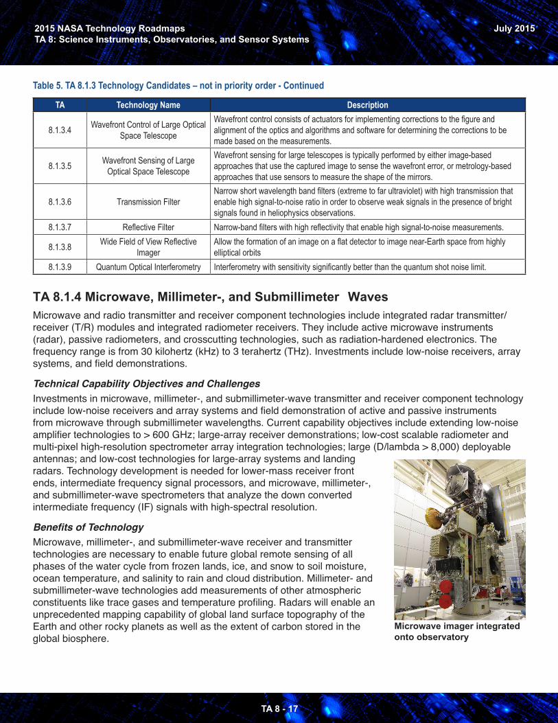
Benefits of TechnologyMicrowave, millimeter-, and submillimeter-wave receiver and transmitter technologies are necessary to enable future global remote sensing of all phases of the water cycle from frozen lands, ice, and snow to soil moisture, ocean temperature, and salinity to rain and cloud distribution. Millimeter- and submillimeter-wave technologies add measurements of other atmospheric constituents like trace gases and temperature profiling. Radars will enable an unprecedented mapping capability of global land surface topography of the Earth and other rocky planets as well as the extent of carbon stored in the global biosphere.
Microwave imager integrated onto observatory
2015 NASA Technology RoadmapsTA 8: Science Instruments, Observatories, and Sensor Systems
TA 8 - 18
July 2015
Table 6. TA 8.1.4 Technology Candidates – not in priority orderTA Technology Name Description
8.1.4.1 High-Density, Low-Cost Phased Array Panel
Phased arrays provide radar beam steering agility that enables new radar measurement concepts. New integrated circuit technologies (e.g., mixed-signal silicon-Germanium, or SiGe) enable higher densities, lower noise figures, and lower costs.
8.1.4.2 High-Efficiency Pulsed Radar Transmitter
Pulsed radar transmitters with high efficiencies at all wavelengths to enable or reduce cost for both Earth and planetary radar missions.
8.1.4.3 Millimeter-Wave Multi-Frequency Active Feed Array (Radar)
Active (steerable) source of multiple frequencies positioned around the focal locus of a collimating reflector to achieve collocated, multiparametric radar measurements.
8.1.4.4 Low-Cost Landing/Proximity Radar Small, low-cost, radar and proximity sensor suitable for planetary landing missions.
8.1.4.5 Tunable Multi-Pixel Submillimeter-Wave Spectrometer High-resolution multi-pixel submillimeter-wave spectrally tunable array spectrometers.
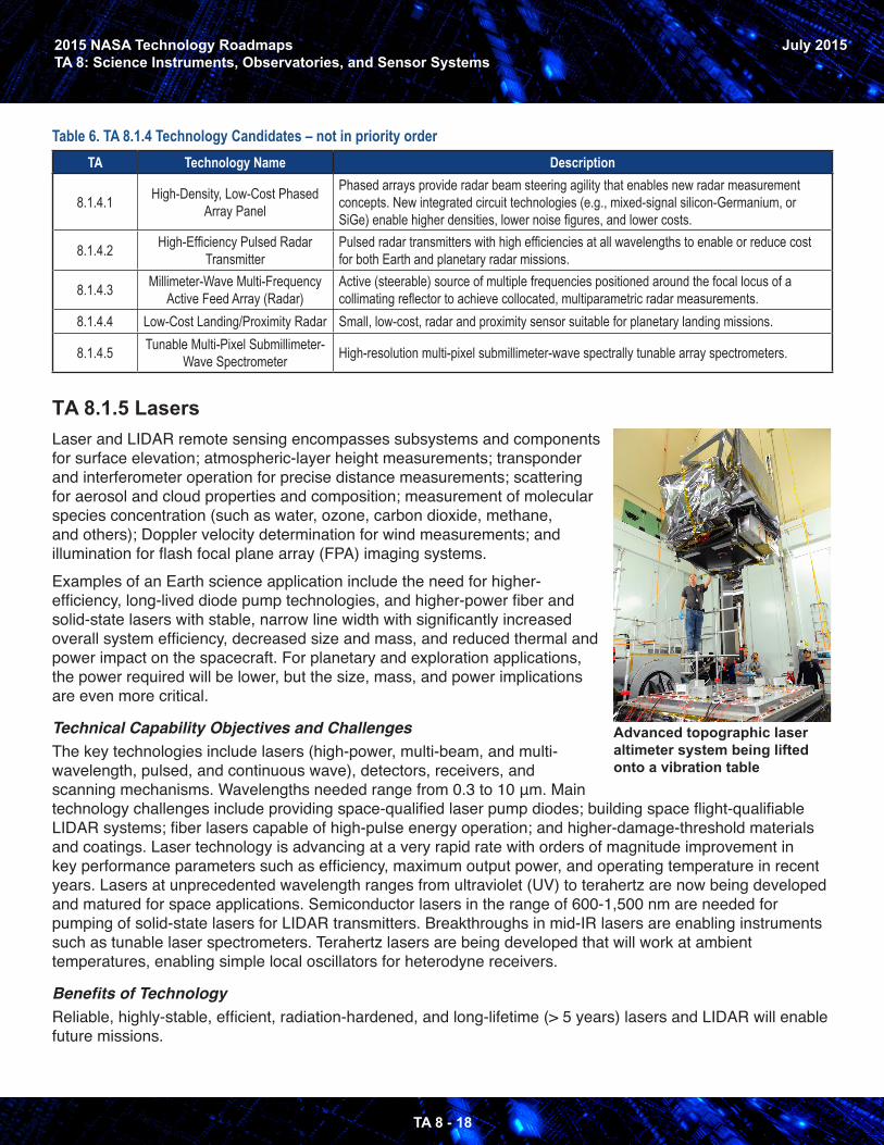
TA 8.1.5 LasersLaser and LIDAR remote sensing encompasses subsystems and components for surface elevation; atmospheric-layer height measurements; transponder and interferometer operation for precise distance measurements; scattering for aerosol and cloud properties and composition; measurement of molecular species concentration (such as water, ozone, carbon dioxide, methane, and others); Doppler velocity determination for wind measurements; and illumination for flash focal plane array (FPA) imaging systems. Examples of an Earth science application include the need for higher-efficiency, long-lived diode pump technologies, and higher-power fiber and solid-state lasers with stable, narrow line width with significantly increased overall system efficiency, decreased size and mass, and reduced thermal and power impact on the spacecraft. For planetary and exploration applications, the power required will be lower, but the size, mass, and power implications are even more critical.
Technical Capability Objectives and ChallengesThe key technologies include lasers (high-power, multi-beam, and multi-wavelength, pulsed, and continuous wave), detectors, receivers, and scanning mechanisms. Wavelengths needed range from 0.3 to 10 μm. Main technology challenges include providing space-qualified laser pump diodes; building space flight-qualifiable LIDAR systems; fiber lasers capable of high-pulse energy operation; and higher-damage-threshold materials and coatings. Laser technology is advancing at a very rapid rate with orders of magnitude improvement in key performance parameters such as efficiency, maximum output power, and operating temperature in recent years. Lasers at unprecedented wavelength ranges from ultraviolet (UV) to terahertz are now being developed and matured for space applications. Semiconductor lasers in the range of 600-1,500 nm are needed for pumping of solid-state lasers for LIDAR transmitters. Breakthroughs in mid-IR lasers are enabling instruments such as tunable laser spectrometers. Terahertz lasers are being developed that will work at ambient temperatures, enabling simple local oscillators for heterodyne receivers.
Benefits of TechnologyReliable, highly-stable, efficient, radiation-hardened, and long-lifetime (> 5 years) lasers and LIDAR will enable future missions.
Advanced topographic laser altimeter system being lifted onto a vibration table
2015 NASA Technology RoadmapsTA 8: Science Instruments, Observatories, and Sensor Systems
TA 8 - 19
July 2015
Table 7. TA 8.1.5 Technology Candidates – not in priority orderTA Technology Name Description
8.1.5.1 2.05 µm Pulsed Laser 2.05 micron pulsed laser for LIDAR measurements.
8.1.5.2 355 nm, Single-Frequency Pulsed Laser
355 nm pulsed laser used for backscatter from molecules to determine wind speed at high altitudes.
8.1.5.3 Pulsed Lasers for Altimetry, Earth Short-pulsed 1-micron lasers used with fast detectors to perform time of flight measurements.
8.1.5.4 Three-Dimensional (3D) Imaging Flash Light Detection and Ranging (LIDAR)
LIDAR to produce surface elevation maps on centimeter scales at distances of 2 km for uncooperative targets and 5km for cooperative targets.
8.1.5.5 0.765/1.572 µm Pulsed Laser A dual-channel laser is used in a laser absorption spectrometer (1.57 micron) to detect carbon dioxide and to measure surface pressure (0.765 micron).
8.1.5.6 Seed Laser Continuous wave (CW) diode or fiber seed sources used to tune lasers over a range of wavelengths.
8.1.5.7 Pulsed Laser 1064 nanometer (nm) LIDAR used for generating surface elevation maps and surface feature mapping.
8.1.5.8 Pulsed Tunable Near Infrared/Infrared Laser (Gas Detection)
In-situ source for gas detection and typing, IR lasers proposed for LIDAR detection or entry, descent, and landing (EDL) application.
8.1.5.9 Continuous Wave Tunable Near Infrared/Infrared for Gas Detection In-situ laser source for gas detection and characterization.
8.1.5.10 1.65 µm Pulsed Light Detection and Ranging (LIDAR)
Lasers operating in this wavelength band have been identified as good candidates for remote methane sensing.
8.1.5.11 Light Detection and Ranging (LIDAR) Fiber Transmitter
Advanced fiber-based laser transmitter with 0.01 to 20 millijoule (mJ) pulse energy in the visible to near-IR for LIDARs.
8.1.5.12 Diode Laser for Vector Helium Magnetometer (VHM) Ultra-narrow laser systems needed to make high precision magnetic field measurement.
8.1.5.13 Laser Interferometer Space-based lasers for interferometry.
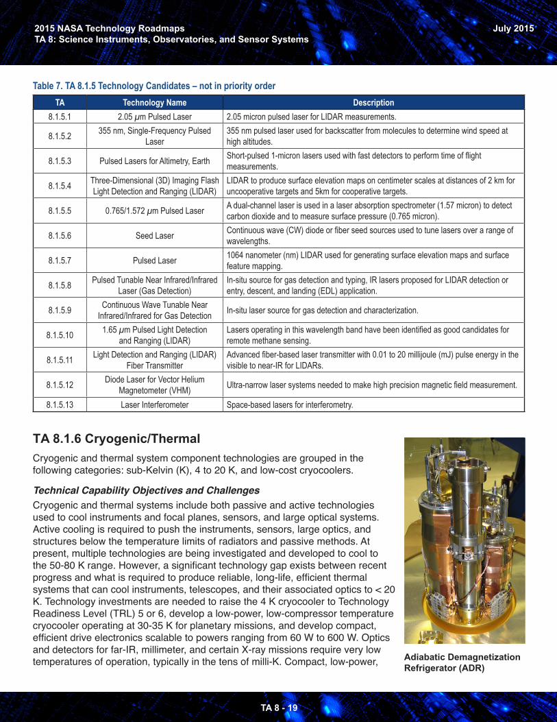
TA 8.1.6 Cryogenic/ThermalCryogenic and thermal system component technologies are grouped in the following categories: sub-Kelvin (K), 4 to 20 K, and low-cost cryocoolers.
Technical Capability Objectives and ChallengesCryogenic and thermal systems include both passive and active technologies used to cool instruments and focal planes, sensors, and large optical systems. Active cooling is required to push the instruments, sensors, large optics, and structures below the temperature limits of radiators and passive methods. At present, multiple technologies are being investigated and developed to cool to the 50-80 K range. However, a significant technology gap exists between recent progress and what is required to produce reliable, long-life, efficient thermal systems that can cool instruments, telescopes, and their associated optics to < 20 K. Technology investments are needed to raise the 4 K cryocooler to Technology Readiness Level (TRL) 5 or 6, develop a low-power, low-compressor temperature cryocooler operating at 30-35 K for planetary missions, and develop compact, efficient drive electronics scalable to powers ranging from 60 W to 600 W. Optics and detectors for far-IR, millimeter, and certain X-ray missions require very low temperatures of operation, typically in the tens of milli-K. Compact, low-power, Adiabatic Demagnetization
Refrigerator (ADR)
2015 NASA Technology RoadmapsTA 8: Science Instruments, Observatories, and Sensor Systems
TA 8 - 20
July 2015
lightweight coolers suitable for space flight are needed to provide this cooling. Low-cost, highly efficient, hardened coolers are seen as an enabling capability for future small satellite and unmanned aerial vehicle (UAV) applications.
Benefits of TechnologyCryogenic and thermal systems that are low power, lightweight, and with low exported vibration will enhance future missions.
Table 8. TA 8.1.6 Technology Candidates – not in priority orderTA Technology Name Description
8.1.6.1 4 K Cryocooler Advanced spaceflight pulse tube, Stirling, Joule-Thomson and turbo-Brayton cryocoolers.
8.1.6.2 Continuous Sub-K Refrigerator Adiabatic Demagnetization Refrigerator (ADR) or He3/He4 dilution refrigerator that can be directly coupled to mechanical cryocoolers.
8.1.6.3 Low Cost Cryocooler Low-cost single-stage cryocooler for cooling sensors and optics.
2015 NASA Technology RoadmapsTA 8: Science Instruments, Observatories, and Sensor Systems
TA 8 - 21
July 2015
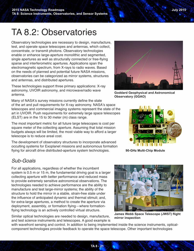
TA 8.2: Observatories Observatory technologies are necessary to design, manufacture, test, and operate space telescopes and antennas, which collect, concentrate, or transmit photons. Observatory technologies enable or enhance large-aperture monolithic and segmented, single apertures as well as structurally connected or free-flying sparse and interferometric apertures. Applications span the electromagnetic spectrum, from X-rays to radio waves. Based on the needs of planned and potential future NASA missions, observatories can be categorized as mirror systems, structures and antennas, and distributed apertures.These technologies support three primary applications: X-ray astronomy, UVOIR astronomy, and microwave/radio wave antenna. Many of NASA’s survey missions currently define the state of the art and pull requirements for X-ray astronomy. NASA’s space telescopes and commercial imaging systems represent the state of the art in UVOIR. Push requirements for extremely large space telescopes (ELST) are in the 15 to 30 meter (m) class range. The most important metric for all future large telescopes is cost per square meter of the collecting aperture. Assuming that total mission budgets always will be limited, the most viable way to afford a larger telescope is to reduce areal cost. The development of observatory structures to incorporate advanced occulting systems for Exoplanet missions and autonomous formation flying for aircraft drive distributed-aperture system technologies.
Sub-Goals For all applications, regardless of whether the incumbent system is 0.5 m or 15 m, the fundamental driving goal is a larger collecting aperture with better performance and reduced mass to provide extremely sensitive astronomical observations. The technologies needed to achieve performance are the ability to manufacture and test large-mirror systems; the ability of the structure to hold the mirror in a stable, strain-free state under the influence of anticipated dynamic and thermal stimuli; and, for extra-large apertures, a method to create the aperture via deployment, assembly, or formation flying—where formation-flying technology is an actively controlled virtual structure. Similar optical technologies are needed to design, manufacture, and test science instruments and telescopes. A good example is with wavefront sensing and control. In addition to being implemented inside the science instruments, optical-component technologies provide feedback to operate the space telescope. Other important technologies
Goddard Geophysical and Astronomical Observatory (GGAO)
James Webb Space Telescope (JWST) flightmirror inspection
90-GHz Multi-Chip Module
2015 NASA Technology RoadmapsTA 8: Science Instruments, Observatories, and Sensor Systems
TA 8 - 22
July 2015
include validated performance models that integrate optical, mechanical, dynamic, and thermal models for telescopes, structures, instruments, and spacecraft. These technologies enable the design and manufacture of observatories whose performance requirements cannot be tested on the ground.
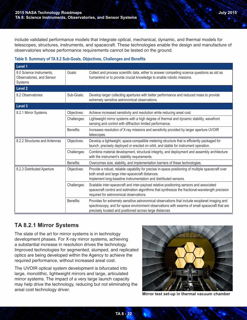
Table 9. Summary of TA 8.2 Sub-Goals, Objectives, Challenges and BenefitsLevel 18.0 Science Instruments, Observatories, and Sensor Systems
Goals: Collect and process scientific data, either to answer compelling science questions as old as humankind or to provide crucial knowledge to enable robotic missions.
Level 28.2 Observatories Sub-Goals: Develop larger collecting apertures with better performance and reduced mass to provide
extremely sensitive astronomical observations.Level 38.2.1 Mirror Systems Objectives: Achieve increased sensitivity and resolution while reducing areal cost.
Challenges: Lightweight mirror systems with a high degree of thermal and dynamic stability, wavefront sensing and control with diffraction limited performance.
Benefits: Increases resolution of X-ray missions and sensitivity provided by larger aperture UVOIR telescopes.
8.2.2 Structures and Antennas Objectives: Develop a lightweight, space-compatible metering structure that is efficiently packaged for launch, precisely deployed or erected on orbit, and stable for instrument operation.
Challenges: Combine material development, structural integrity, and deployment and assembly architecture with the instrument’s stability requirements.
Benefits: Overcomes size, stability, and implementation barriers of these technologies.8.2.3 Distributed Aperture Objectives: Provide a robust, reliable capability for precise in-space positioning of multiple spacecraft over
both small and large inter-spacecraft distances.Implement long-baseline instrumentation and distributed sensors.
Challenges: Scalable inter-spacecraft and inter-payload relative positioning sensors and associated spacecraft control and estimation algorithms that synthesize the fractional-wavelength precision required for astronomical observations.
Benefits: Provides for extremely sensitive astronomical observations that include exoplanet imaging and spectroscopy, and for space environment observations with swarms of small spacecraft that are precisely located and positioned across large distances
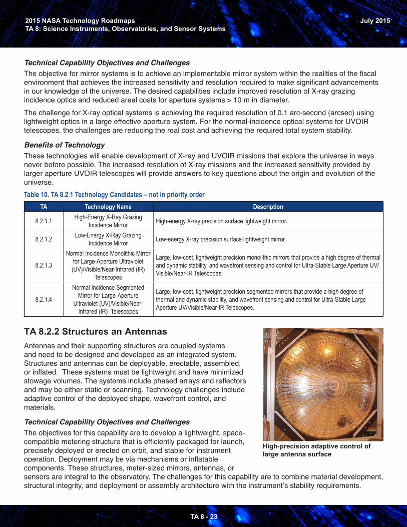
TA 8.2.1 Mirror SystemsThe state of the art for mirror systems is in technology development phases. For X-ray mirror systems, achieving a substantial increase in resolution drives the technology. Improved technologies for segmented, slumped, and replicated optics are being developed within the Agency to achieve the required performance, without increased areal cost.The UVOIR optical system development is bifurcated into large, monolithic, lightweight mirrors and large, articulated mirror systems. The impact of a very large launch capacity may help drive the technology, reducing but not eliminating the areal cost technology driver.
Mirror test set-up in thermal vacuum chamber
2015 NASA Technology RoadmapsTA 8: Science Instruments, Observatories, and Sensor Systems
TA 8 - 23
July 2015
Technical Capability Objectives and ChallengesThe objective for mirror systems is to achieve an implementable mirror system within the realities of the fiscal environment that achieves the increased sensitivity and resolution required to make significant advancements in our knowledge of the universe. The desired capabilities include improved resolution of X-ray grazing incidence optics and reduced areal costs for aperture systems > 10 m in diameter.The challenge for X-ray optical systems is achieving the required resolution of 0.1 arc-second (arcsec) using lightweight optics in a large effective aperture system. For the normal-incidence optical systems for UVOIR telescopes, the challenges are reducing the real cost and achieving the required total system stability.
Benefits of TechnologyThese technologies will enable development of X-ray and UVOIR missions that explore the universe in ways never before possible. The increased resolution of X-ray missions and the increased sensitivity provided by larger aperture UVOIR telescopes will provide answers to key questions about the origin and evolution of the universe.Table 10. TA 8.2.1 Technology Candidates – not in priority order
TA Technology Name Description
8.2.1.1 High-Energy X-Ray Grazing Incidence Mirror High-energy X-ray precision surface lightweight mirror.
8.2.1.2 Low-Energy X-Ray Grazing Incidence Mirror Low-energy X-ray precision surface lightweight mirror.
8.2.1.3
Normal Incidence Monolithic Mirror for Large-Aperture Ultraviolet (UV)/Visible/Near-Infrared (IR)
Telescopes
Large, low-cost, lightweight precision monolithic mirrors that provide a high degree of thermal and dynamic stability, and wavefront sensing and control for Ultra-Stable Large Aperture UV/Visible/Near-IR Telescopes.
8.2.1.4
Normal Incidence Segmented Mirror for Large-Aperture
Ultraviolet (UV)/Visible/Near-Infrared (IR) Telescopes
Large, low-cost, lightweight precision segmented mirrors that provide a high degree of thermal and dynamic stability, and wavefront sensing and control for Ultra-Stable Large Aperture UV/Visible/Near-IR Telescopes.
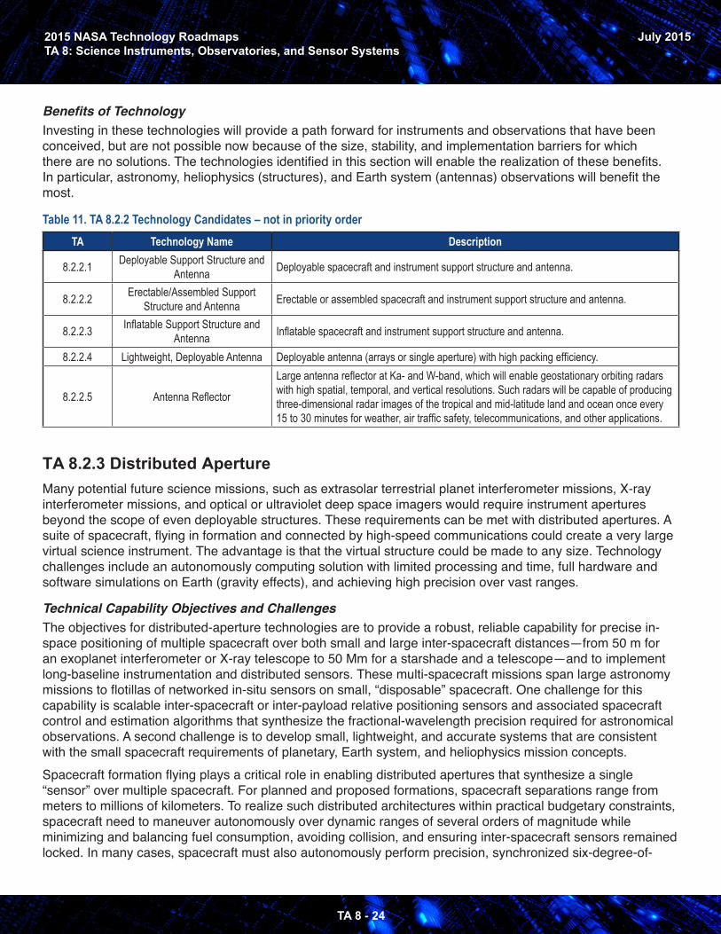
TA 8.2.2 Structures an Antennas Antennas and their supporting structures are coupled systems and need to be designed and developed as an integrated system. Structures and antennas can be deployable, erectable, assembled, or inflated. These systems must be lightweight and have minimized stowage volumes. The systems include phased arrays and reflectors and may be either static or scanning. Technology challenges include adaptive control of the deployed shape, wavefront control, and materials.
Technical Capability Objectives and ChallengesThe objectives for this capability are to develop a lightweight, space-compatible metering structure that is efficiently packaged for launch, precisely deployed or erected on orbit, and stable for instrument operation. Deployment may be via mechanisms or inflatable components. These structures, meter-sized mirrors, antennas, or sensors are integral to the observatory. The challenges for this capability are to combine material development, structural integrity, and deployment or assembly architecture with the instrument’s stability requirements.
High-precision adaptive control oflarge antenna surface
2015 NASA Technology RoadmapsTA 8: Science Instruments, Observatories, and Sensor Systems
TA 8 - 24
July 2015
Benefits of TechnologyInvesting in these technologies will provide a path forward for instruments and observations that have been conceived, but are not possible now because of the size, stability, and implementation barriers for which there are no solutions. The technologies identified in this section will enable the realization of these benefits. In particular, astronomy, heliophysics (structures), and Earth system (antennas) observations will benefit the most.
Table 11. TA 8.2.2 Technology Candidates – not in priority orderTA Technology Name Description
8.2.2.1 Deployable Support Structure and Antenna Deployable spacecraft and instrument support structure and antenna.
8.2.2.2 Erectable/Assembled Support Structure and Antenna Erectable or assembled spacecraft and instrument support structure and antenna.
8.2.2.3 Inflatable Support Structure and Antenna Inflatable spacecraft and instrument support structure and antenna.
8.2.2.4 Lightweight, Deployable Antenna Deployable antenna (arrays or single aperture) with high packing efficiency.
8.2.2.5 Antenna Reflector
Large antenna reflector at Ka- and W-band, which will enable geostationary orbiting radars with high spatial, temporal, and vertical resolutions. Such radars will be capable of producing three-dimensional radar images of the tropical and mid-latitude land and ocean once every 15 to 30 minutes for weather, air traffic safety, telecommunications, and other applications.
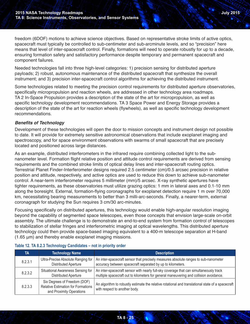
TA 8.2.3 Distributed Aperture Many potential future science missions, such as extrasolar terrestrial planet interferometer missions, X-ray interferometer missions, and optical or ultraviolet deep space imagers would require instrument apertures beyond the scope of even deployable structures. These requirements can be met with distributed apertures. A suite of spacecraft, flying in formation and connected by high-speed communications could create a very large virtual science instrument. The advantage is that the virtual structure could be made to any size. Technology challenges include an autonomously computing solution with limited processing and time, full hardware and software simulations on Earth (gravity effects), and achieving high precision over vast ranges.
Technical Capability Objectives and ChallengesThe objectives for distributed-aperture technologies are to provide a robust, reliable capability for precise in-space positioning of multiple spacecraft over both small and large inter-spacecraft distances—from 50 m for an exoplanet interferometer or X-ray telescope to 50 Mm for a starshade and a telescope—and to implement long-baseline instrumentation and distributed sensors. These multi-spacecraft missions span large astronomy missions to flotillas of networked in-situ sensors on small, “disposable” spacecraft. One challenge for this capability is scalable inter-spacecraft or inter-payload relative positioning sensors and associated spacecraft control and estimation algorithms that synthesize the fractional-wavelength precision required for astronomical observations. A second challenge is to develop small, lightweight, and accurate systems that are consistent with the small spacecraft requirements of planetary, Earth system, and heliophysics mission concepts.Spacecraft formation flying plays a critical role in enabling distributed apertures that synthesize a single “sensor” over multiple spacecraft. For planned and proposed formations, spacecraft separations range from meters to millions of kilometers. To realize such distributed architectures within practical budgetary constraints, spacecraft need to maneuver autonomously over dynamic ranges of several orders of magnitude while minimizing and balancing fuel consumption, avoiding collision, and ensuring inter-spacecraft sensors remained locked. In many cases, spacecraft must also autonomously perform precision, synchronized six-degree-of-
2015 NASA Technology RoadmapsTA 8: Science Instruments, Observatories, and Sensor Systems
TA 8 - 25
July 2015
freedom (6DOF) motions to achieve science objectives. Based on representative stroke limits of active optics, spacecraft must typically be controlled to sub-centimeter and sub-arcminute levels, and so “precision” here means that level of inter-spacecraft control. Finally, formations will need to operate robustly for up to a decade, ensuring formation safety and satisfactory performance despite temporary and permanent spacecraft and component failures. Needed technologies fall into three high-level categories: 1) precision sensing for distributed aperture payloads; 2) robust, autonomous maintenance of the distributed spacecraft that synthesize the overall instrument; and 3) precision inter-spacecraft control algorithms for achieving the distributed instrument.Some technologies related to meeting the precision control requirements for distributed aperture observatories, specifically micropropulsion and reaction wheels, are addressed in other technology area roadmaps. TA 2 In-Space Propulsion provides a description of the state of the art for micropropulsion, as well as specific technology development recommendations. TA 3 Space Power and Energy Storage provides a description of the state of the art for reaction wheels (flywheels), as well as specific technology development recommendations.
Benefits of TechnologyDevelopment of these technologies will open the door to mission concepts and instrument design not possible to date. It will provide for extremely sensitive astronomical observations that include exoplanet imaging and spectroscopy, and for space environment observations with swarms of small spacecraft that are precisely located and positioned across large distances.As an example, distributed interferometers in the infrared require combining collected light to the sub-nanometer level. Formation flight relative position and attitude control requirements are derived from sensing requirements and the combined stroke limits of optical delay lines and inter-spacecraft routing optics. Terrestrial Planet Finder-Interferometer designs required 2.5 centimeter (cm)/0.5 arcsec precision in relative position and attitude, respectively, and active optics are used to reduce this down to achieve sub-nanometer control. A near-term interferometer requires 5 millimeter (mm)/5 arcsec. X-ray synthetic apertures have tighter requirements, as these observatories must utilize grazing optics: 1 mm in lateral axes and 0.1-10 mm along the boresight. External, formation-flying coronagraphs for exoplanet detection require 1 m over 70,000 km, necessitating bearing measurements to better than 3 milli-arc-seconds. Finally, a nearer-term, external coronagraph for studying the Sun requires 3 cm/30 arc-minutes. Focusing specifically on distributed apertures, this technology would enable high-angular resolution imaging beyond the capability of segmented space telescopes, even those concepts that envision large-scale on-orbit assembly. The ultimate challenge is to demonstrate an end-to-end system from formation control of telescopes to stabilization of stellar fringes and interferometric imaging at optical wavelengths. This distributed aperture technology could then provide space-based imaging equivalent to a 400-m telescope separation at H-band (1.65 μm) and thereby enable exoplanet imaging missions.
Table 12. TA 8.2.3 Technology Candidates – not in priority orderTA Technology Name Description
8.2.3.1 Ultra-Precise Absolute Ranging for Distributed Aperture
An inter-spacecraft sensor that precisely measures absolute ranges to sub-nanometer accuracy between spacecraft separated by up to kilometers.
8.2.3.2 Situational Awareness Sensing for Distributed Aperture
An inter-spacecraft sensor with nearly full-sky coverage that can simultaneously track multiple spacecraft out to kilometers for general maneuvering and collision avoidance.
8.2.3.3Six Degrees of Freedom (DOF)
Relative Estimation for Formations and Proximity Operations
An algorithm to robustly estimate the relative rotational and translational state of a spacecraft with respect to another body.
2015 NASA Technology RoadmapsTA 8: Science Instruments, Observatories, and Sensor Systems
TA 8 - 26
July 2015
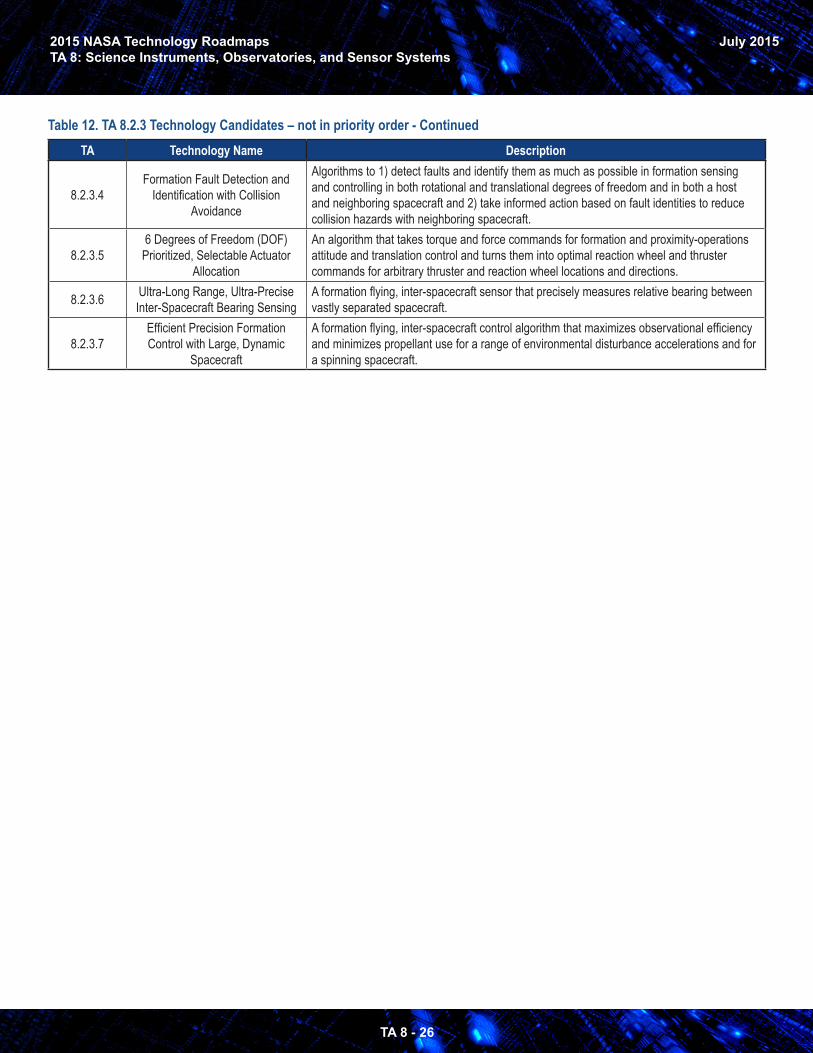
Table 12. TA 8.2.3 Technology Candidates – not in priority order - ContinuedTA Technology Name Description
8.2.3.4Formation Fault Detection and
Identification with Collision Avoidance
Algorithms to 1) detect faults and identify them as much as possible in formation sensing and controlling in both rotational and translational degrees of freedom and in both a host and neighboring spacecraft and 2) take informed action based on fault identities to reduce collision hazards with neighboring spacecraft.
8.2.3.56 Degrees of Freedom (DOF)
Prioritized, Selectable Actuator Allocation
An algorithm that takes torque and force commands for formation and proximity-operations attitude and translation control and turns them into optimal reaction wheel and thruster commands for arbitrary thruster and reaction wheel locations and directions.
8.2.3.6 Ultra-Long Range, Ultra-Precise Inter-Spacecraft Bearing Sensing
A formation flying, inter-spacecraft sensor that precisely measures relative bearing between vastly separated spacecraft.
8.2.3.7Efficient Precision Formation Control with Large, Dynamic
Spacecraft
A formation flying, inter-spacecraft control algorithm that maximizes observational efficiency and minimizes propellant use for a range of environmental disturbance accelerations and for a spinning spacecraft.
2015 NASA Technology RoadmapsTA 8: Science Instruments, Observatories, and Sensor Systems
TA 8 - 27
July 2015
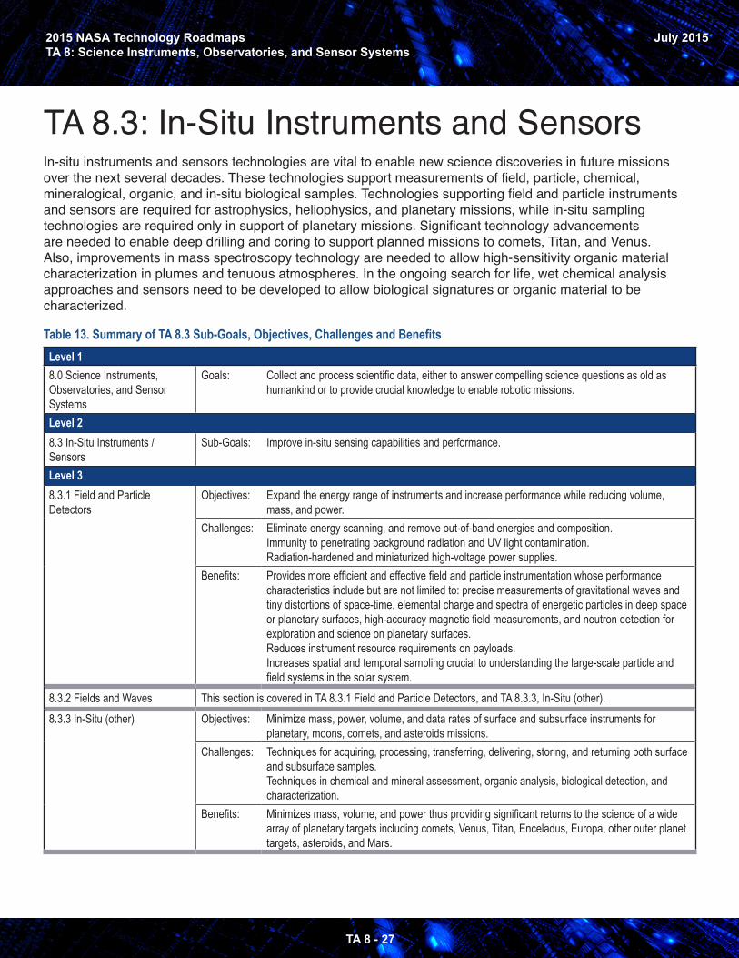
TA 8.3: In-Situ Instruments and Sensors In-situ instruments and sensors technologies are vital to enable new science discoveries in future missions over the next several decades. These technologies support measurements of field, particle, chemical, mineralogical, organic, and in-situ biological samples. Technologies supporting field and particle instruments and sensors are required for astrophysics, heliophysics, and planetary missions, while in-situ sampling technologies are required only in support of planetary missions. Significant technology advancements are needed to enable deep drilling and coring to support planned missions to comets, Titan, and Venus. Also, improvements in mass spectroscopy technology are needed to allow high-sensitivity organic material characterization in plumes and tenuous atmospheres. In the ongoing search for life, wet chemical analysis approaches and sensors need to be developed to allow biological signatures or organic material to be characterized.
Table 13. Summary of TA 8.3 Sub-Goals, Objectives, Challenges and BenefitsLevel 18.0 Science Instruments, Observatories, and Sensor Systems
Goals: Collect and process scientific data, either to answer compelling science questions as old as humankind or to provide crucial knowledge to enable robotic missions.
Level 28.3 In-Situ Instruments / Sensors
Sub-Goals: Improve in-situ sensing capabilities and performance.
Level 38.3.1 Field and Particle Detectors
Objectives: Expand the energy range of instruments and increase performance while reducing volume, mass, and power.
Challenges: Eliminate energy scanning, and remove out-of-band energies and composition.Immunity to penetrating background radiation and UV light contamination.Radiation-hardened and miniaturized high-voltage power supplies.
Benefits: Provides more efficient and effective field and particle instrumentation whose performance characteristics include but are not limited to: precise measurements of gravitational waves and tiny distortions of space-time, elemental charge and spectra of energetic particles in deep space or planetary surfaces, high-accuracy magnetic field measurements, and neutron detection for exploration and science on planetary surfaces. Reduces instrument resource requirements on payloads.Increases spatial and temporal sampling crucial to understanding the large-scale particle and field systems in the solar system.
8.3.2 Fields and Waves This section is covered in TA 8.3.1 Field and Particle Detectors, and TA 8.3.3, In-Situ (other).8.3.3 In-Situ (other) Objectives: Minimize mass, power, volume, and data rates of surface and subsurface instruments for
planetary, moons, comets, and asteroids missions.Challenges: Techniques for acquiring, processing, transferring, delivering, storing, and returning both surface
and subsurface samples.Techniques in chemical and mineral assessment, organic analysis, biological detection, and characterization.
Benefits: Minimizes mass, volume, and power thus providing significant returns to the science of a wide array of planetary targets including comets, Venus, Titan, Enceladus, Europa, other outer planet targets, asteroids, and Mars.
2015 NASA Technology RoadmapsTA 8: Science Instruments, Observatories, and Sensor Systems
TA 8 - 28
July 2015
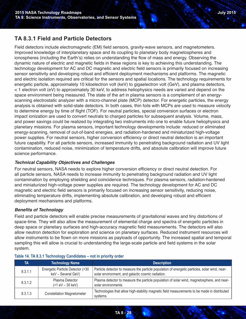
TA 8.3.1 Field and Particle DetectorsField detectors include electromagnetic (EM) field sensors, gravity-wave sensors, and magnetometers. Improved knowledge of interplanetary space and its coupling to planetary body magnetospheres and ionospheres (including the Earth’s) relies on understanding the flow of mass and energy. Observing the dynamic nature of electric and magnetic fields in these regions is key to achieving this understanding. The technology development for AC and DC magnetic and electric field sensors is primarily focused on increasing sensor sensitivity and developing robust and efficient deployment mechanisms and platforms. The magnetic and electric isolation required are critical for the sensors and spatial locations. The technology requirements for energetic particle, approximately 10 kiloelectron volt (keV) to gigaelectron volt (GeV), and plasma detectors, < 1 electron volt (eV) to approximately 30 keV, to address heliophysics needs are varied and depend on the space environment being measured. The state of the art in plasma sensors is a complement of an energy-scanning electrostatic analyzer with a micro-channel plate (MCP) detector. For energetic particles, the energy analysis is obtained with solid-state detectors. In both cases, thin foils with MCPs are used to measure velocity to determine energy by time of flight (TOF). For neutral particles, special conversion surfaces or electron impact ionization are used to convert neutrals to charged particles for subsequent analysis. Volume, mass, and power savings could be realized by integrating two instruments into one to enable future heliophysics and planetary missions. For plasma sensors, important technology developments include: reduced or eliminated energy-scanning, removal of out-of-band energies, and radiation-hardened and miniaturized high-voltage power supplies. For neutral sensors, higher conversion efficiency or direct neutral detection is an important future capability. For all particle sensors, increased immunity to penetrating background radiation and UV light contamination, reduced noise, minimization of temperature drifts, and absolute calibration will improve future science performance.
Technical Capability Objectives and ChallengesFor neutral sensors, NASA needs to explore higher conversion efficiency or direct neutral detection. For all particle sensors, NASA needs to increase immunity to penetrating background radiation and UV light contamination by employing shielding and coincidence techniques. For plasma sensors, radiation-hardened and miniaturized high-voltage power supplies are required. The technology development for AC and DC magnetic and electric field sensors is primarily focused on increasing sensor sensitivity, reducing noise, eliminating temperature drifts, implementing absolute calibration, and developing robust and efficient deployment mechanisms and platforms.
Benefits of TechnologyField and particle detectors will enable precise measurements of gravitational waves and tiny distortions of space-time. They will also allow the measurement of elemental charge and spectra of energetic particles in deep space or planetary surfaces and high-accuracy magnetic field measurements. The detectors will also allow neutron detection for exploration and science on planetary surfaces. Reduced instrument resources will allow instruments to be flown on more missions as payloads of opportunity. The increased spatial and temporal sampling this will allow is crucial to understanding the large-scale particle and field systems in the solar system. Table 14. TA 8.3.1 Technology Candidates – not in priority order
TA Technology Name Description
8.3.1.1 Energetic Particle Detector (>30 keV – Several GeV)
Particle detector to measure the particle population of energetic particles, solar wind, near-solar environment, and galactic cosmic radiation.
8.3.1.2 Plasma Detector (<1 eV – 30 keV)
Plasma detector to measure the particle population of solar wind, magnetosphere, and near-solar environments.
8.3.1.3 Constellation Magnetometer Technologies that allow high-stability magnetic field measurements to be made in distributed systems.
2015 NASA Technology RoadmapsTA 8: Science Instruments, Observatories, and Sensor Systems
TA 8 - 29
July 2015
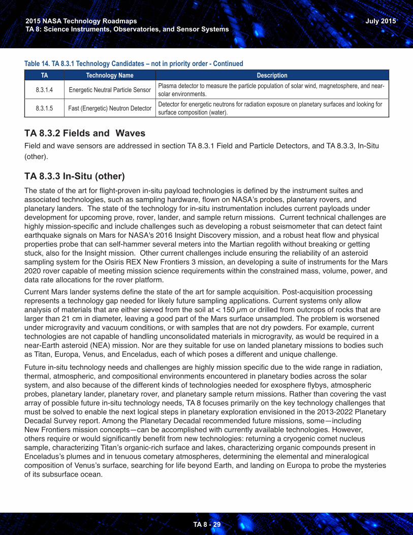
Table 14. TA 8.3.1 Technology Candidates – not in priority order - ContinuedTA Technology Name Description
8.3.1.4 Energetic Neutral Particle Sensor Plasma detector to measure the particle population of solar wind, magnetosphere, and near-solar environments.
8.3.1.5 Fast (Energetic) Neutron Detector Detector for energetic neutrons for radiation exposure on planetary surfaces and looking for surface composition (water).
TA 8.3.2 Fields and Waves Field and wave sensors are addressed in section TA 8.3.1 Field and Particle Detectors, and TA 8.3.3, In-Situ (other).
TA 8.3.3 In-Situ (other)The state of the art for flight-proven in-situ payload technologies is defined by the instrument suites and associated technologies, such as sampling hardware, flown on NASA’s probes, planetary rovers, and planetary landers. The state of the technology for in-situ instrumentation includes current payloads under development for upcoming prove, rover, lander, and sample return missions. Current technical challenges are highly mission-specific and include challenges such as developing a robust seismometer that can detect faint earthquake signals on Mars for NASA's 2016 Insight Discovery mission, and a robust heat flow and physical properties probe that can self-hammer several meters into the Martian regolith without breaking or getting stuck, also for the Insight mission. Other current challenges include ensuring the reliability of an asteroid sampling system for the Osiris REX New Frontiers 3 mission, an developing a suite of instruments for the Mars 2020 rover capable of meeting mission science requirements within the constrained mass, volume, power, and data rate allocations for the rover platform.Current Mars lander systems define the state of the art for sample acquisition. Post-acquisition processing represents a technology gap needed for likely future sampling applications. Current systems only allow analysis of materials that are either sieved from the soil at < 150 µm or drilled from outcrops of rocks that are larger than 21 cm in diameter, leaving a good part of the Mars surface unsampled. The problem is worsened under microgravity and vacuum conditions, or with samples that are not dry powders. For example, current technologies are not capable of handling unconsolidated materials in microgravity, as would be required in a near-Earth asteroid (NEA) mission. Nor are they suitable for use on landed planetary missions to bodies such as Titan, Europa, Venus, and Enceladus, each of which poses a different and unique challenge.Future in-situ technology needs and challenges are highly mission specific due to the wide range in radiation, thermal, atmospheric, and compositional environments encountered in planetary bodies across the solar system, and also because of the different kinds of technologies needed for exosphere flybys, atmospheric probes, planetary lander, planetary rover, and planetary sample return missions. Rather than covering the vast array of possible future in-situ technology needs, TA 8 focuses primarily on the key technology challenges that must be solved to enable the next logical steps in planetary exploration envisioned in the 2013-2022 Planetary Decadal Survey report. Among the Planetary Decadal recommended future missions, some—including New Frontiers mission concepts—can be accomplished with currently available technologies. However, others require or would significantly benefit from new technologies: returning a cryogenic comet nucleus sample, characterizing Titan’s organic-rich surface and lakes, characterizing organic compounds present in Enceladus’s plumes and in tenuous cometary atmospheres, determining the elemental and mineralogical composition of Venus’s surface, searching for life beyond Earth, and landing on Europa to probe the mysteries of its subsurface ocean.
2015 NASA Technology RoadmapsTA 8: Science Instruments, Observatories, and Sensor Systems
TA 8 - 30
July 2015
Because the identified in-situ exploration technology needs flow primarily from the well-studied design reference missions from the 2013-2022 Planetary Decadal Survey report, TA 8 does not provide detailed specifications on other in-situ technology challenges for future missions, such as Discovery-class concepts:simple, rugged sampling technologies for an in-situ lander or rover; low-mass, low-power technologies for chemical and mineral assessment, organic analysis, biological detection and characterization; and others. Planetary protection is also not a main focus because none of the Decadal Survey Design Reference Missions presented any unusual planetary protection technology challenges. Additionally, two current NASA missions under development, Mars 2020 and the Europa mission, will be maturing a host of new planetary protection methodologies from which future in-situ instruments will benefit. Technical Capability Objectives and ChallengesAmong the wide range of planetary missions envisioned over the next 20 years, the most technically challenging are those that require in-situ drilling, sampling, and analysis capabilities. These missions will benefit from NASA’s sustained investments over the last two decades in technologies for in-situ exploration. As a result of already flown and under-development missions, planetary scientists can leverage existing capabilities developed for in-situ atmospheric, organic, mineralogical, elemental, and geophysical analyses. However, due to the extreme diversity of in-situ planetary environments, from Titan’s organic-rich cryogenic surface to Venus’s high-temperature and high-pressure rocky surface to Europa’s radiation-sputtered, water-rich cryogenic surface, there are few “one size fits all” technologies that can be readily transferred from one in-situ planetary mission to another. For this reason, future in-situ technology development needs tend to be highly mission-specific. The only common feature is that, even more so than for remote instruments and observatories, all in-situ missions require aggressive minimization of instrument mass, power, volume, and, in some cases, data rate. Among the future planetary science missions recommended in “Visions and Voyages for Planetary Science in the Decade 2013-2022,” several require new in-situ sampling technologies, including the ability to encapsulate and return a cryogenic sample with preserved stratigraphy obtained from a comet nucleus to a depth of ≥ 25 cm, maintained at ≤ 125 K. A Titan lander mission is strongly advised for the future to determine the molecular and isotopic composition of Titan’s lakes and solid surface. This Titan mission would require a mechanical system for transferring solid and liquid cryogenic samples from ambient Titan conditions to an analytical suite. Finally, a main science objective of a future Venus lander mission would be to determine the surface elemental and mineralogical composition. Technology advancements in high-temperature and high-pressure actuators, drills, and valves would enable these measurements to be conducted inside a Venus lander with analytical instruments.Various missions planned for the next two decades involve flybys and orbiters sent to bodies with tenuous atmospheres and perhaps plume activity including Enceladus, Europa, Titan, and comets. Of particular interest is the molecular and isotopic composition of any organic species present in these tenuous atmospheres. Detecting and characterizing these organic species, which may be present at only 10s to 100s of particles per cubic centimeter, will require an ultra-sensitive mass spectrometer with either very high-mass resolution (> 10,000) or another means of distinguishing between compounds with nearly identical masses, such as MSn capability. Measuring the charged particles (positive and negative ions) in both high-radiation and low-radiation environments is important to understand the processes at work in the deep oceans of the icy moons. The challenge is to increase maximal count rates to 100 Megahertz (MHz), a factor of 10 increase, in both environments.
Instrument for sample analysis on Mars
2015 NASA Technology RoadmapsTA 8: Science Instruments, Observatories, and Sensor Systems
TA 8 - 31
July 2015
Past, present, and planned future in-situ missions commonly employ Vis-IR spectrometers, laser-based spectrometers, and X-ray spectrometers to study atmospheric phenomena and surface composition. These spectrometers will benefit from advanced detector and focal plane technologies (TA 8.1.1) and lasertechnologies (TA 8.1.5) discussed elsewhere in this section. In addition, future X-ray instrumentation such as a micro X-ray fluorescence spectrometer to determine micro-scale elemental composition, or a compact X-ray diffraction instrument to study mineralogical composition, require compact X-ray sources (high-voltage power supplies and X-ray emitters) to be compatible with the low-mass, low-power requirements for landed missions to Venus, asteroids, comets, and other planetary bodies.A long-standing objective of the planetary science community is to determine whether other habitable environments and perhaps even life itself can be found outside of Earth. Several approaches for in-situ life detection have been partially matured for flight applications utilizing wet chemical analysis techniques for identifying in-situ biological signatures. Future missions that seek to determine whether life arose on another planetary body would benefit from further maturation of wet chemical analysis techniques that can search for biological signatures such as amino acid chirality and carboxylic acid chain length distributions, among others.A future Europa lander mission will require a payload that can withstand Europa’s high-radiation environment and strict planetary protection requirements. The development of this lander will benefit from knowledge and lessons learned during the development of NASA’s other lander missions, but will also require lander-specific technology developments in these areas.
For the Moon and Mars, the Decadal Survey calls for continued development of in-situ geochronology capability. This is because the estimation of absolute ages of events in Solar System history relies on the calibration of a relative age scale, determined from crater counting on terrains, by a small number of radioisotopic dates of Apollo samples from the Moon. The cratering curve deduced for the Moon has been extrapolated to Mercury, Venus, Mars, and even the Earth, where the record of ancient impacts has been lost to us by erosion, weathering, and plate tetonics. Moreover, the bombardment chronology inferred from the Apollo samples has played a significant role in the development of the favored model of early Solar System dynamics. However, the impactor flux estimates may be biased by the fact that the Apollo era samples were mostly collected out of their original geological contexts, or were tenuously connected to an assumed context. In addition, new lunar crater counts using the high-resolution imaging capability of the Lunar Reconnaissance Orbiter Camera indicate that previous terrain age determinations may have been underestimated by up to 1.1 Ga for the era from 3.6 to 1 Ga, an interval for which few Apollo samples exist. Given the uncertainties, measurements for dating precision of better than ~±200 Ma for planetary-aged samples, quantification of sources of bias and error, and integrated low-complexity sample handling and preparation are required.
Finally, future landed missions such as the New Frontiers 5 Lunar Geophysical Network (LGN) mission candidate, and a possible Europa Lander as part of the upcoming Europa mission, will require highly sensitive seismometers to allow better understanding of the processes that shaped the solar system's planets and moons. These advanced seismometers will allow precision measurements of quakes and other internal activity to better understand the planetary body's geophysical history and interior structure. They will require a 10-fold increase in sensitivity over current technology, while operating over a wide thermal range and in a harsh radiation environment.
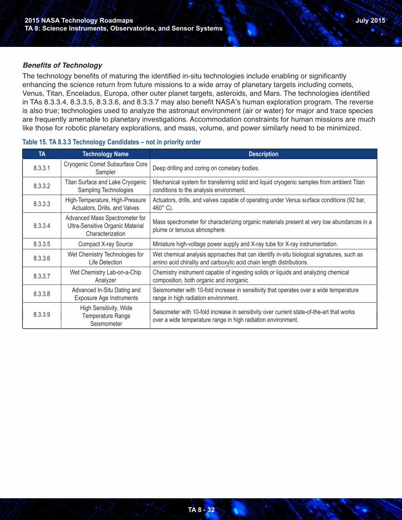
2015 NASA Technology RoadmapsTA 8: Science Instruments, Observatories, and Sensor Systems
TA 8 - 32
July 2015
Benefits of TechnologyThe technology benefits of maturing the identified in-situ technologies include enabling or significantly enhancing the science return from future missions to a wide array of planetary targets including comets, Venus, Titan, Enceladus, Europa, other outer planet targets, asteroids, and Mars. The technologies identified in TAs 8.3.3.4, 8.3.3.5, 8.3.3.6, and 8.3.3.7 may also benefit NASA’s human exploration program. The reverse is also true; technologies used to analyze the astronaut environment (air or water) for major and trace species are frequently amenable to planetary investigations. Accommodation constraints for human missions are much like those for robotic planetary explorations, and mass, volume, and power similarly need to be minimized.
Table 15. TA 8.3.3 Technology Candidates – not in priority orderTA Technology Name Description
8.3.3.1 Cryogenic Comet Subsurface Core Sampler Deep drilling and coring on cometary bodies.
8.3.3.2 Titan Surface and Lake Cryogenic Sampling Technologies
Mechanical system for transferring solid and liquid cryogenic samples from ambient Titan conditions to the analysis environment.
8.3.3.3 High-Temperature, High-Pressure Actuators, Drills, and Valves
Actuators, drills, and valves capable of operating under Venus surface conditions (92 bar, 460° C).
8.3.3.4Advanced Mass Spectrometer for Ultra-Sensitive Organic Material
Characterization
Mass spectrometer for characterizing organic materials present at very low abundances in a plume or tenuous atmosphere.
8.3.3.5 Compact X-ray Source Miniature high-voltage power supply and X-ray tube for X-ray instrumentation.
8.3.3.6 Wet Chemistry Technologies for Life Detection
Wet chemical analysis approaches that can identify in-situ biological signatures, such as amino acid chirality and carboxylic acid chain length distributions.
8.3.3.7 Wet Chemistry Lab-on-a-Chip Analyzer
Chemistry instrument capable of ingesting solids or liquids and analyzing chemical composition, both organic and inorganic
8.3.3.8 Advanced In-Situ Dating and Exposure Age Instruments
Seismometer with 10-fold increase in sensitivity that operates over a wide temperature range in high radiation environment.
8.3.3.9High Sensitivity, Wide Temperature Range
Seismometer
Seisometer with 10-fold increase in sensitivity over current state-of-the-art that works over a wide temperature range in high radiation environment.
2015 NASA Technology RoadmapsTA 8: Science Instruments, Observatories, and Sensor Systems
TA 8 - 33
July 2015
AppendixAcronyms2D Two Dimensional3D Three DimensionalAC Alternating CurrentACE Aerosol-Cloud-EcosystemsADR Adiabatic Demagnetization RefrigeratorAFF Autonomous Formation FlyingAFTA Astrophysics Focused Telescope AssetsAPD Avalanche DiodesAPIO Advanced Planning and Integration OfficeASCENDS Active Sensing of CO2 Emissions over Nights, Days, and SeasonsASIC Application-Specific Integrated CircuitATLAST Advanced Technology Large Aperture Space TelescopeBIRD Barrier Infrared DetectorBLIP Background-Limited Infrared PhotonCCD Charged Coupled DeviceCheMin Chemical Mineral InstrumentCMB Cosmic Microwave BackgroundCMOS Complementary Metal-Oxide SemiconductorCW Continuous WaveDC Direct CurrentDIAL Differential Absorption LIDARDOF Degrees of FreedomDRM Design Reference MissionDYNAMIC DYnamical Neutral AtMosphere-Ionosphere CouplingEDL Entry, Descent, and LandingELST Extremely Large Space TelescopesEM ElectroMagneticENA Energetic Neutral AtomsEUV Extreme UltraVioletEVA Extra Vehicular ActivityFOV Field of ViewFPA Focal Plane ArrayFPGA Field-Programmable Gate ArrayFUV Far UltraVioletFWHM Full Width Half MaximumGACM Global Atmospheric Composition MissionGDC Geospace Dynamics ConstellationGEO Geosynchronous OrbitGGAO Goddard Geophysical and Astronomical ObservatoryGPS Global Positioning SatelliteGRACE Gravity Recovery And Climate ExperimentHEO Highly Elliptical Orbit
2015 NASA Technology RoadmapsTA 8: Science Instruments, Observatories, and Sensor Systems
TA 8 - 34
July 2015
HST HyspIRI I&T IAE IF IMAP IR ISS JWSTLIBSLIDAR LIGO LIST LOLA MCP MEDICI MIRO MKID MLA MLS MOLA MSL NASA NEA NIR NIS NRC NSR NuSTAR OCT OSIRIS-Rex QE RF ROIC SAM SAR SCLP SDO SEAA SNR SOA SQUID SSCA STS TA TABS TES TIR
Hubble Space TelescopeHyperspectral InfraRed ImagerInformation Tand echnologyInflatable Antenna ExperimentIntermediate FrequencyInterstellar MApping ProbeInfraRedInternational Space StationJames Web Space TelescopeLaser Induced Breakdown SpectroscopyLIght Detection and RangingLaser Interferometer Gravitational wave ObservatoryLIDAR Surface TopographyLunar Orbiter Laser AltimeterMicroChannel PlateMagnetosphere Energetics, Dynamics, and Ionospheric Coupling Investigation Microwave Instrument for the Rosetta OrbiterMicrowave Kinetic Inductance DetectorMercury Laser AltimeterMicrowave Limb SounderMars Orbiter Laser AltimeterMars Science LabNational Aeronautics and Space AdministrationNear-Earth AsteroidNear InfraRedNormal Insulator SuperconductorNational Research CouncilNASA Sounding RocketsNUclear Spectroscopic Telescope ARrayOffice of the Chief TechnologistOrigins-Spectral Interpretation-Resource Identification-Security-Regolith EXplorer Quantum EfficiencyRadio FrequencyReadOut Integrated CircuitSample Analysis at MarsSynthetic Aperture RadarSnow and Cold Land ProcessesSolar Dynamics ObservatoryStatic Energy Angle AnalyzerSignal-to-Noise RatioState Of the ArtSuperconducting QUantum Interference DeviceSoil Sample Collection AssemblySpace Transportation SystemTechnology AreaTechnology Area Breakdown StructureTransition Edge SensorsTotal Internal Reflection
2015 NASA Technology RoadmapsTA 8: Science Instruments, Observatories, and Sensor Systems
TA 8 - 35
July 2015
TOF Time Of FlightTPF-I Terrestrial Planet Finder-InterferometerT/R Transmitter/ReceiverTRL Technology Readiness LevelUAV Unmanned Aerial VehicleUV UltraVioletUVOIR UltraViolet/Optical/InfraRedUV/Vis/NIR/IR UltraViolet/Visible/Near-InfraRed/InfraRedVHM Vector Helium Magnetometer VTP Virtual Terrain Project WFIRST Wide-Field Infrared Survey TelescopeWFSC Wavefront Sensing and Control
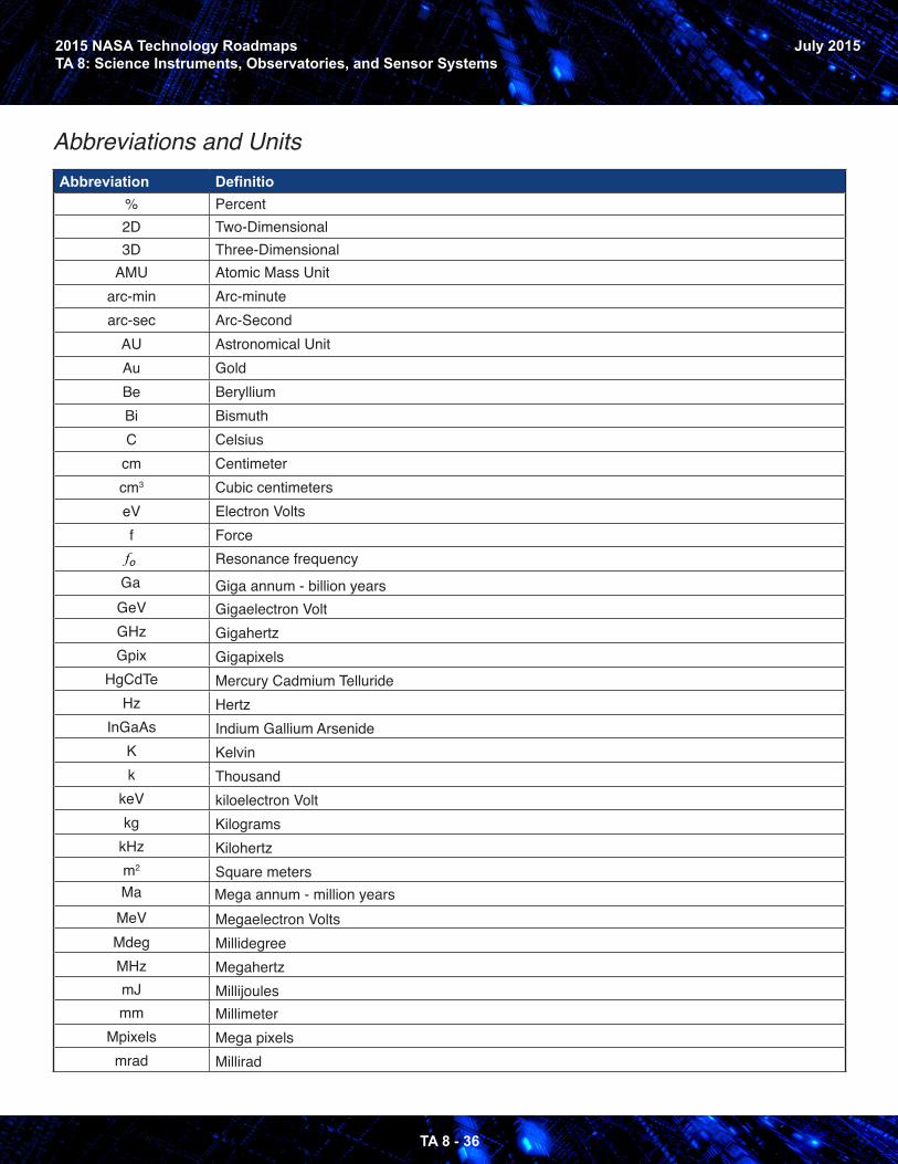
2015 NASA Technology RoadmapsTA 8: Science Instruments, Observatories, and Sensor Systems
TA 8 - 36
July 2015
Abbreviations and UnitsAbbreviation Definitio
% Percent2D Two-Dimensional3D Three-Dimensional
AMU Atomic Mass Unitarc-min Arc-minutearc-sec Arc-Second
AU Astronomical UnitAu GoldBe BerylliumBi BismuthC Celsius
cm Centimetercm3 Cubic centimeterseV Electron Voltsf Force
fo Resonance frequencyGa Giga annum - billion yearsGeV Gigaelectron VoltGHz GigahertzGpix Gigapixels
HgCdTe Mercury Cadmium TellurideHz Hertz
InGaAs Indium Gallium ArsenideK Kelvink Thousand
keV kiloelectron Voltkg Kilograms
kHz Kilohertzm2 Square metersMa Mega annum - million years
MeV Megaelectron VoltsMdeg MillidegreeMHz MegahertzmJ Millijoulesmm Millimeter
Mpixels Mega pixelsmrad Millirad
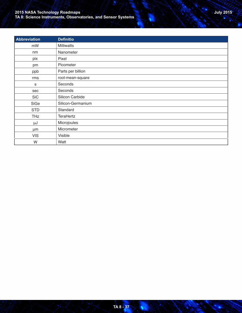
2015 NASA Technology RoadmapsTA 8: Science Instruments, Observatories, and Sensor Systems
TA 8 - 37
July 2015
Abbreviation DefinitiomW Milliwattsnm Nanometerpix Pixelpm Picometerppb Parts per billionrms root-mean-square
s Secondssec SecondsSiC Silicon Carbide
SiGe Silicon-GermaniumSTD StandardTHz TeraHertzμJ Microjoulesμm MicrometerVIS VisibleW Watt
2015 NASA Technology RoadmapsTA 8: Science Instruments, Observatories, and Sensor Systems
TA 8 - 38
July 2015
Contributors
TECHNOLOGY AREA ROADMAP DEVELOPMENT TEAM
William EdwardsTA 8 ChairNASA, Langley Research Center
Daniel WinterhalterTA 8 Co-ChairNASA, Jet Propulsion Laboratory
Faith Chandler, Director, Strategic Integration, OCTNASA, Headquarters
Jill BaumanNASA, Ames Research Center
Terence DoironNASA, Goddard Space Flight Center
Sabrina FeldmanNASA, Jet Propulsion Laboratory
George KomarEarth Science Technology Office
Keith MurrayNASA, Langley Research Center
James F . SpanNASA, Marshall Space Flight Center
OTHER CONTRIBUTORSMatt BolcarNASA, Goddard Space Flight Center
Sandra CauffmanNASA, Headquarters
Garry FlemingNASA, Langley Research Center
Stephen J . HoraNASA, Langley Research Center
Sharon JefferiesNASA, Headquarters
Orlando MelendezNASA, Headquarters
Nikolaos PaschalidisNASA, Goddard Space Flight Center
Brian RamseyNASA, Marshall Space Flight Center
Eric SilkNASA, Goddard Space Flight Center
Jeffrey S . SmitNASA, Goddard Space Flight Center
Phil Stahl,NASA, Marshall Space Flight Center
Carl StahleNASA, Goddard Space Flight Center
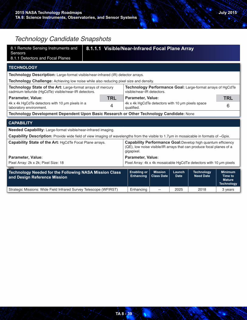
2015 NASA Technology RoadmapsTA 8: Science Instruments, Observatories, and Sensor Systems
TA 8 - 39
July 2015
Technology Candidate Snapshots8.1 Remote Sensing Instruments and Sensors 8.1.1 Detectors and Focal Planes
8.1.1.1 Visible/Near-Infrared Focal Plane Array
TECHNOLOGY
Technology Description: Large-format visible/near-infrared (IR) detector arrays. Technology Challenge: Achieving low noise while also reducing pixel size and density. Technology State of the Art: Large-format arrays of mercury cadmium telluride (HgCdTe) visible/near-IR detectors. Parameter, Value: 4k x 4k HgCdTe detectors with 10 µm pixels in a laboratory environment.
TRL4
Technology Performance Goal: Large-format arrays of HgCdTe visible/near-IR detectors.Parameter, Value: 4k x 4k HgCdTe detectors with 10 µm pixels space qualified.
TRL6
Technology Development Dependent Upon Basic Research or Other Technology Candidate: None
CAPABILITYNeeded Capability: Large-format visible/near-infrared imaging. Capability Description: Provide wide field of view imaging of wavelengths from the visible to 1.7μm in mosaicable in formats of ~Gpix.Capability State of the Art: HgCdTe Focal Plane arrays.
Parameter, Value: Pixel Array: 2k x 2k; Pixel Size: 18 μm
Capability Performance Goal:Develop high quantum efficiency (QE), low noise visible/IR arrays that can produce focal planes of a gigapixel. Parameter, Value: Pixel Array: 4k x 4k mosaicable HgCdTe detectors with 10 µm pixels
Technology Needed for the Following NASA Mission Class and Design Reference Mission
Enabling or Enhancing
Mission Class Date
Launch Date
Technology Need Date
Minimum Time to Mature
Technology
Strategic Missions: Wide Field Infrared Survey Telescope (WFIRST) Enhancing -- 2025 2018 3 years

2015 NASA Technology RoadmapsTA 8: Science Instruments, Observatories, and Sensor Systems
July 2015
TA 8 - 40
8.1 Remote Sensing Instruments and Sensors 8.1.1 Detectors and Focal Planes
8.1.1.2 Infrared Focal Plane
TECHNOLOGY
Technology Description: Infrared focal planes for imagers, spectrometers, and imaging-spectrometers.Technology Challenge: Detector material, detector fabrication, digital readout integrated circuit, higher-temperature operation, lower dark current.Technology State of the Art: Barrier Infrared Detector (BIRD), a breakthrough technology.Parameter, Value: Quantum Efficiency (QE): 77%;Format: 2k x 2k;Pixel operability: 99.98%;Pixel uniformity: 99.8%;1/f noise knee: < 0.5 Hz
TRL3
Technology Performance Goal: 4K x 4K BIRD digital focal plane arrays.Parameter, Value: All digital, QE: 90%;Format: 4k x 4k;Pixel operability: 99.98%;Pixel uniformity: 99.8%;1/f noise knee: < 0.1 Hz
TRL6
Technology Development Dependent Upon Basic Research or Other Technology Candidate: None
CAPABILITYNeeded Capability: High-performance, large-format digital infrared focal planes.Capability Description: High quantum efficiency, high pixel operability, high pixel uniformity, and lower 1/f noise large format infrared focal planes in 1-15 microns spectral range.Capability State of the Art: Mercury cadmium telluride (HgCdTe)
Parameter, Value: QE: 70%;Format: 1k x 1k;Pixel operability: 98%;Pixel uniformity: 95%;1/f noise knee: 1 KHz
Capability Performance Goal: 2k x 2k focal planes with high pixel operability, uniformity, and lower 1/f noise.Parameter, Value: QE: 80%;Format: 2k x 2k;Pixel operability: 99.9%;Pixel uniformity: 99%;1/f noise knee: < 10 Hz
Technology Needed for the Following NASA Mission Class and Design Reference Mission
Enabling or Enhancing
Mission Class Date
Launch Date
Technology Need Date
Minimum Time to Mature
Technology
Planetary Flagship: Europa Enhancing -- 2022* 2019 3 yearsNew Frontiers: Venus In-Situ Explorer Enabling -- 2024 2016 2 years
*Launch date is estimated and not in Agency Mission Planning Model (AMPM)
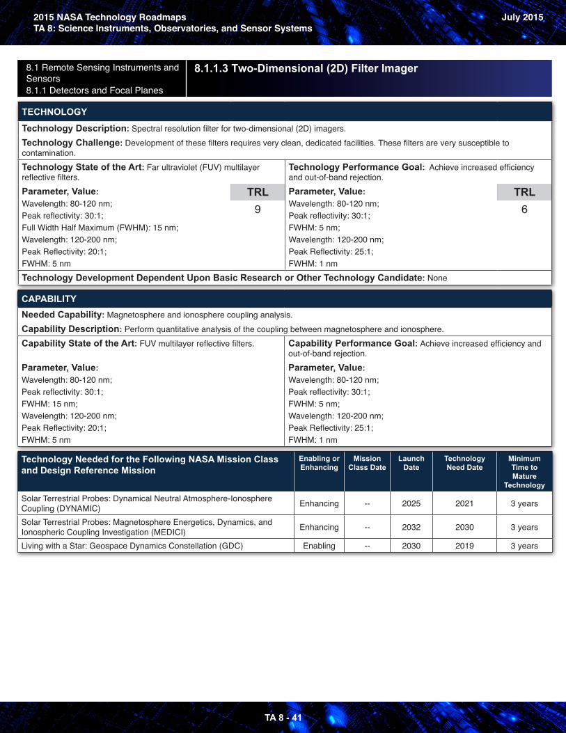
2015 NASA Technology RoadmapsTA 8: Science Instruments, Observatories, and Sensor Systems
July 2015
TA 8 - 41
8.1 Remote Sensing Instruments and Sensors 8.1.1 Detectors and Focal Planes
8.1.1.3 Two-Dimensional (2D) Filter Imager
TECHNOLOGY
Technology Description: Spectral resolution filter for two-dimensional (2D) imagers.Technology Challenge: Development of these filters requires very clean, dedicated facilities. These filters are very susceptible to contamination. Technology State of the Art: Far ultraviolet (FUV) multilayer reflective filters.Parameter, Value: Wavelength: 80-120 nm;Peak reflectivity: 30:1;Full Width Half Maximum (FWHM): 15 nm;Wavelength: 120-200 nm;Peak Reflectivity: 20:1;FWHM: 5 nm
TRL9
Technology Performance Goal: Achieve increased efficiency and out-of-band rejection.Parameter, Value: Wavelength: 80-120 nm;Peak reflectivity: 30:1;FWHM: 5 nm;Wavelength: 120-200 nm;Peak Reflectivity: 25:1;FWHM: 1 nm
TRL6
Technology Development Dependent Upon Basic Research or Other Technology Candidate: None
CAPABILITYNeeded Capability: Magnetosphere and ionosphere coupling analysis.Capability Description: Perform quantitative analysis of the coupling between magnetosphere and ionosphere.Capability State of the Art: FUV multilayer reflective filters.
Parameter, Value: Wavelength: 80-120 nm;Peak reflectivity: 30:1;FWHM: 15 nm;Wavelength: 120-200 nm;Peak Reflectivity: 20:1;FWHM: 5 nm
Capability Performance Goal: Achieve increased efficiency and out-of-band rejection.Parameter, Value: Wavelength: 80-120 nm;Peak reflectivity: 30:1;FWHM: 5 nm;Wavelength: 120-200 nm;Peak Reflectivity: 25:1;FWHM: 1 nm
Technology Needed for the Following NASA Mission Class and Design Reference Mission
Enabling or Enhancing
Mission Class Date
Launch Date
Technology Need Date
Minimum Time to Mature
Technology
Solar Terrestrial Probes: Dynamical Neutral Atmosphere-Ionosphere Coupling (DYNAMIC) Enhancing -- 2025 2021 3 years
Solar Terrestrial Probes: Magnetosphere Energetics, Dynamics, and Ionospheric Coupling Investigation (MEDICI) Enhancing -- 2032 2030 3 years
Living with a Star: Geospace Dynamics Constellation (GDC) Enabling -- 2030 2019 3 years
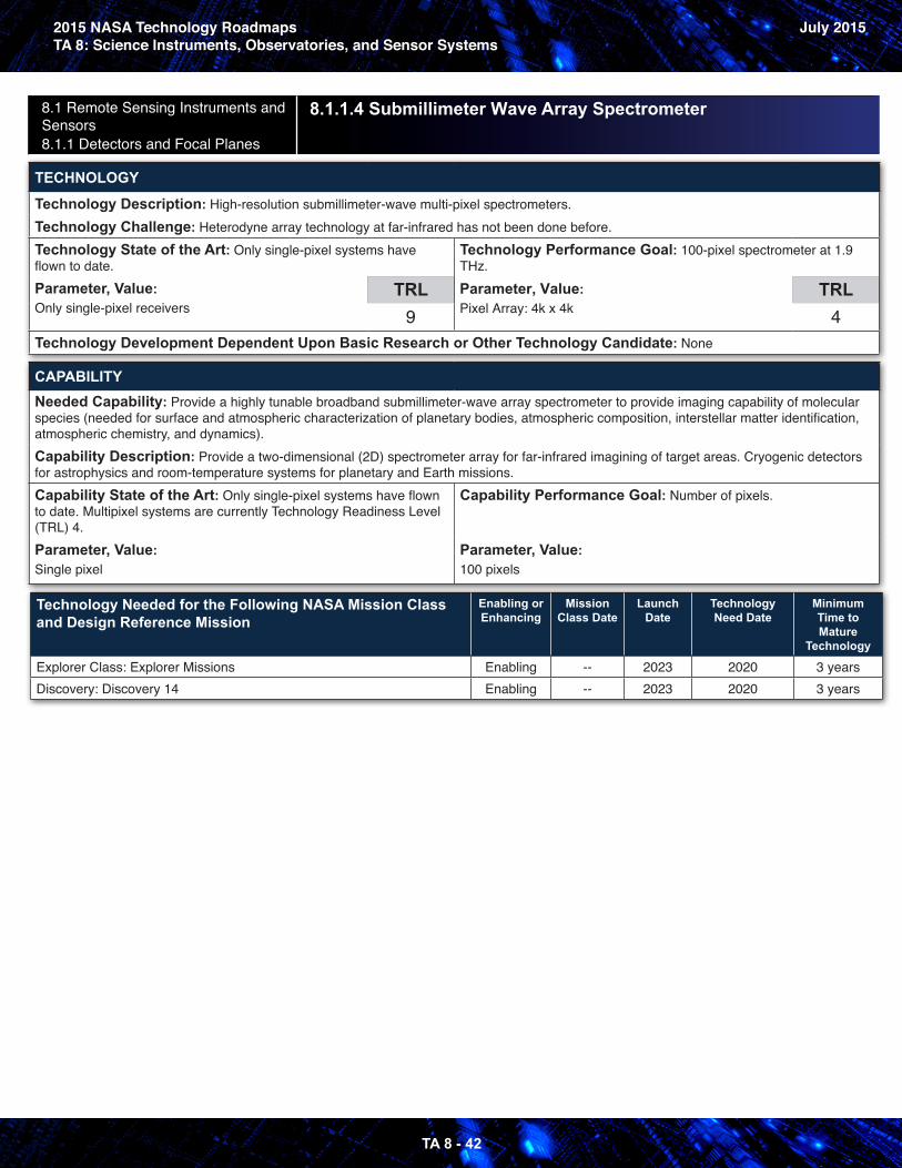
2015 NASA Technology RoadmapsTA 8: Science Instruments, Observatories, and Sensor Systems
July 2015
TA 8 - 42
8.1 Remote Sensing Instruments and Sensors 8.1.1 Detectors and Focal Planes
8.1.1.4 Submillimeter Wave Array Spectrometer
TECHNOLOGY
Technology Description: High-resolution submillimeter-wave multi-pixel spectrometers.Technology Challenge: Heterodyne array technology at far-infrared has not been done before. Technology State of the Art: Only single-pixel systems have flown to date.Parameter, Value: Only single-pixel receivers
TRL9
Technology Performance Goal: 100-pixel spectrometer at 1.9 THz.Parameter, Value: Pixel Array: 4k x 4k
TRL4
Technology Development Dependent Upon Basic Research or Other Technology Candidate: None
CAPABILITYNeeded Capability: Provide a highly tunable broadband submillimeter-wave array spectrometer to provide imaging capability of molecular species (needed for surface and atmospheric characterization of planetary bodies, atmospheric composition, interstellar matter identification, atmospheric chemistry, and dynamics).Capability Description: Provide a two-dimensional (2D) spectrometer array for far-infrared imagining of target areas. Cryogenic detectors for astrophysics and room-temperature systems for planetary and Earth missions. Capability State of the Art: Only single-pixel systems have flown to date. Multipixel systems are currently Technology Readiness Level (TRL) 4.Parameter, Value: Single pixel
Capability Performance Goal: Number of pixels.
Parameter, Value: 100 pixels
Technology Needed for the Following NASA Mission Class and Design Reference Mission
Enabling or Enhancing
Mission Class Date
Launch Date
Technology Need Date
Minimum Time to Mature
Technology
Explorer Class: Explorer Missions Enabling -- 2023 2020 3 yearsDiscovery: Discovery 14 Enabling -- 2023 2020 3 years
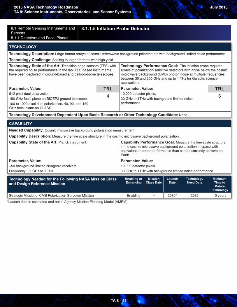
2015 NASA Technology RoadmapsTA 8: Science Instruments, Observatories, and Sensor Systems
July 2015
TA 8 - 43
8.1 Remote Sensing Instruments and Sensors 8.1.1 Detectors and Focal Planes
8.1.1.5 Inflation Probe Detector
TECHNOLOGY
Technology Description: Large format arrays of cosmic microwave background polarimeters with background limited noise performance.Technology Challenge: Scaling to larger formats with high yield.Technology State of the Art: Transition edge sensors (TES) with the required noise performance in the lab. TES-based instruments have been deployed in ground-based and balloon-borne telescopes.
Parameter, Value: 512 pixel dual polarization. 150 GHz focal plane on BICEP2 ground telescope.100 to 1000 pixel dual polarization. 40, 90, and 150 GHz focal plane on CLASS.
TRL4
Technology Performance Goal: The inflation probe requires arrays of polarization-sensitive detectors with noise below the cosmic microwave background (CMB) photon noise at multiple frequencies between 30 and 300 GHz and up to 1 THz for Galactic science applications.Parameter, Value: 10,000 detector pixels.30 GHz to 1THz with background limited noise performance.
TRL6
Technology Development Dependent Upon Basic Research or Other Technology Candidate: None
CAPABILITYNeeded Capability: Cosmic microwave background polarization measurement.Capability Description: Measure the fine scale structure in the cosmic microwave background polarization.Capability State of the Art: Planck instrument.
Parameter, Value: ~50 background-limited cryogenic receivers.Frequency: 27 GHz to 1 THz.
Capability Performance Goal: Measure the fine scale structure in the cosmic microwave background polarization in space with equivalent or better performance than can be currently achieve on Earth.Parameter, Value: 10,000 detector pixels.30 GHz to 1THz with background limited noise performance.
Technology Needed for the Following NASA Mission Class and Design Reference Mission
Enabling or Enhancing
Mission Class Date
Launch Date
Technology Need Date
Minimum Time to Mature
Technology
Strategic Missions: CMB Polarization Surveyor Mission Enabling -- 2035* 2035 10 years*Launch date is estimated and not in Agency Mission Planning Model (AMPM)
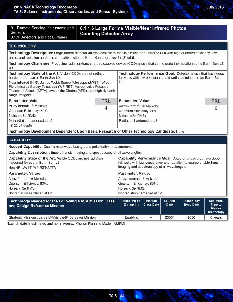
2015 NASA Technology RoadmapsTA 8: Science Instruments, Observatories, and Sensor Systems
July 2015
TA 8 - 44
8.1 Remote Sensing Instruments and Sensors 8.1.1 Detectors and Focal Planes
8.1.1.6 Large Forma Visible/Near Infrared Photon Counting Detector Array
TECHNOLOGY
Technology Description: Large-format detector arrays sensitive to the visible and near-infrared (IR) with high quantum efficiency, low noise, and radiation hardness compatible with the Earth-Sun Lagrange-2 (L2) orbit.Technology Challenge: Producing radiation-hard charged coupled device (CCD) arrays that can tolerate the radiation at the Earth-Sun L2 point.Technology State of the Art: Visible CCDs are not radiation hardened for use at Earth-Sun L2.Near infrared (NIR): James Webb Space Telescope (JWST), Wide-Field Infrared Survey Telescope (WFIRST)-Astrophysics-Focused Telescope Assets (AFTA), Avalanche Diodes (APD), and high dynamic range imagery.Parameter, Value: Array format: 16 Mpixels;Quantum Efficiency: 80%;Noise: < 5e RMS;Not radiation hardened at L2;18-22 bit depth
TRL4
Technology Performance Goal: Detector arrays that have deep full wells with low persistence and radiation tolerance for Earth-Sun L2.
Parameter, Value: Arrays format: 16 Mpixels; Quantum Efficiency: 80%; Noise: < 5e RMS; Radiation hardened at L2
TRL6
Technology Development Dependent Upon Basic Research or Other Technology Candidate: None
CAPABILITYNeeded Capability: Cosmic microwave background polarization measurement.Capability Description: Enable transit imaging and spectroscopy at all wavelengths.Capability State of the Art: Visible CCDs are not radiation hardened for use at Earth-Sun L2.Near-IR: JWST, WFIRST-AFTA.Parameter, Value: Array format: 16 Mpixels; Quantum Efficiency: 80%; Noise: < 5e RMS;Not radiation hardened at L2
Capability Performance Goal: Detector arrays that have deep full wells with low persistence and radiation tolerance enable transit imaging and spectroscopy at all wavelengths.
Parameter, Value: Arrays format: 16 Mpixels; Quantum Efficiency: 80%; Noise: < 5e RMS;Not radiation hardened at L2
Technology Needed for the Following NASA Mission Class and Design Reference Mission
Enabling or Enhancing
Mission Class Date
Launch Date
Technology Need Date
Minimum Time to Mature
Technology
Strategic Missions: Large UV/Visible/IR Surveyor Mission Enabling -- 2035* 2030 8 years*Launch date is estimated and not in Agency Mission Planning Model (AMPM)
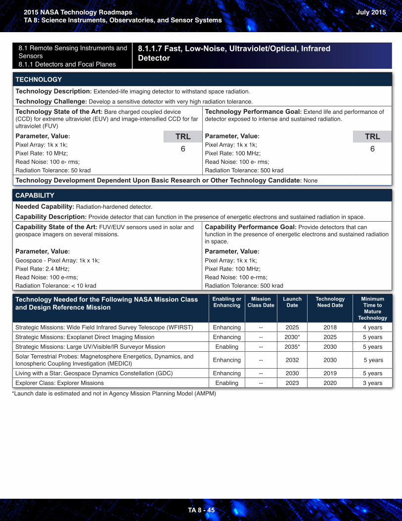
2015 NASA Technology RoadmapsTA 8: Science Instruments, Observatories, and Sensor Systems
July 2015
TA 8 - 45
8.1 Remote Sensing Instruments and Sensors 8.1.1 Detectors and Focal Planes
8.1.1.7 Fast, Low-Noise, Ultraviolet/Optical, Infrared Detector
TECHNOLOGY
Technology Description: Extended-life imaging detector to withstand space radiation.Technology Challenge: Develop a sensitive detector with very high radiation tolerance.Technology State of the Art: Bare charged coupled device (CCD) for extreme ultraviolet (EUV) and image-intensified CCD for far ultraviolet (FUV)Parameter, Value: Pixel Array: 1k x 1k; Pixel Rate: 10 MHz;Read Noise: 100 e- rms;Radiation Tolerance: 50 krad
TRL6
Technology Performance Goal: Extend life and performance of detector exposed to intense and sustained radiation.
Parameter, Value: Pixel Array: 1k x 1k; Pixel Rate: 100 MHz; Read Noise: 100 e- rms;Radiation Tolerance: 500 krad
TRL6
Technology Development Dependent Upon Basic Research or Other Technology Candidate: None
CAPABILITYNeeded Capability: Radiation-hardened detector.Capability Description: Provide detector that can function in the presence of energetic electrons and sustained radiation in space.Capability State of the Art: FUV/EUV sensors used in solar and geospace imagers on several missions.
Parameter, Value: Geospace - Pixel Array: 1k x 1k; Pixel Rate: 2.4 MHz;Read Noise: 100 e-rms; Radiation Tolerance: < 10 krad
Capability Performance Goal: Provide detectors that can function in the presence of energetic electrons and sustained radiation in space.Parameter, Value: Pixel Array: 1k x 1k; Pixel Rate: 100 MHz; Read Noise: 100 e-rms; Radiation Tolerance: 500 krad
Technology Needed for the Following NASA Mission Class and Design Reference Mission
Enabling or Enhancing
Mission Class Date
Launch Date
Technology Need Date
Minimum Time to Mature
Technology
Strategic Missions: Wide Field Infrared Survey Telescope (WFIRST) Enhancing -- 2025 2018 4 yearsStrategic Missions: Exoplanet Direct Imaging Mission Enhancing -- 2030* 2025 5 yearsStrategic Missions: Large UV/Visible/IR Surveyor Mission Enabling -- 2035* 2030 5 yearsSolar Terrestrial Probes: Magnetosphere Energetics, Dynamics, and Ionospheric Coupling Investigation (MEDICI) Enhancing -- 2032 2030 5 years
Living with a Star: Geospace Dynamics Constellation (GDC) Enhancing -- 2030 2019 5 yearsExplorer Class: Explorer Missions Enabling -- 2023 2020 3 years
*Launch date is estimated and not in Agency Mission Planning Model (AMPM)
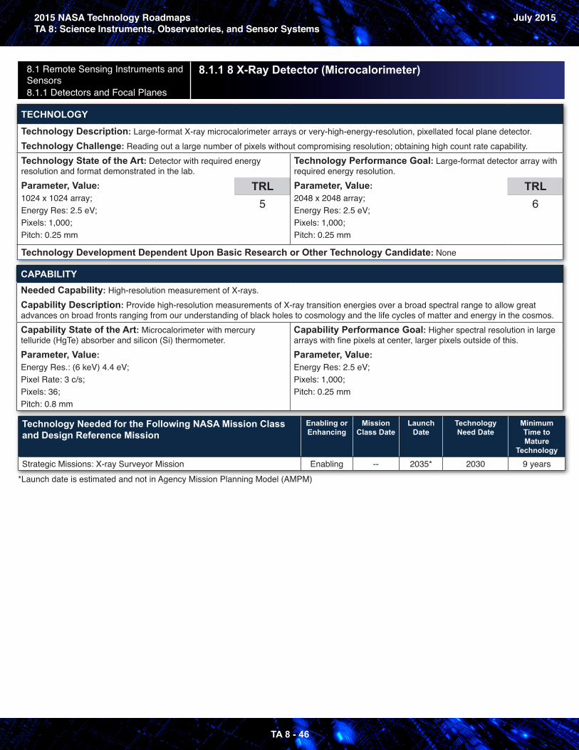
2015 NASA Technology RoadmapsTA 8: Science Instruments, Observatories, and Sensor Systems
July 2015
TA 8 - 46
8.1 Remote Sensing Instruments and Sensors 8.1.1 Detectors and Focal Planes
8.1.1 8 X-Ray Detector (Microcalorimeter)
TECHNOLOGY
Technology Description: Large-format X-ray microcalorimeter arrays or very-high-energy-resolution, pixellated focal plane detector.Technology Challenge: Reading out a large number of pixels without compromising resolution; obtaining high count rate capability.Technology State of the Art: Detector with required energy resolution and format demonstrated in the lab.Parameter, Value: 1024 x 1024 array;Energy Res: 2.5 eV;Pixels: 1,000;Pitch: 0.25 mm
TRL5
Technology Performance Goal: Large-format detector array with required energy resolution.Parameter, Value: 2048 x 2048 array;Energy Res: 2.5 eV;Pixels: 1,000;Pitch: 0.25 mm
TRL6
Technology Development Dependent Upon Basic Research or Other Technology Candidate: None
CAPABILITYNeeded Capability: High-resolution measurement of X-rays.Capability Description: Provide high-resolution measurements of X-ray transition energies over a broad spectral range to allow great advances on broad fronts ranging from our understanding of black holes to cosmology and the life cycles of matter and energy in the cosmos.Capability State of the Art: Microcalorimeter with mercury telluride (HgTe) absorber and silicon (Si) thermometer. Parameter, Value: Energy Res.: (6 keV) 4.4 eV;Pixel Rate: 3 c/s;Pixels: 36;Pitch: 0.8 mm
Capability Performance Goal: Higher spectral resolution in large arrays with fine pixels at center, larger pixels outside of this.Parameter, Value: Energy Res: 2.5 eV;Pixels: 1,000;Pitch: 0.25 mm
Technology Needed for the Following NASA Mission Class and Design Reference Mission
Enabling or Enhancing
Mission Class Date
Launch Date
Technology Need Date
Minimum Time to Mature
Technology
Strategic Missions: X-ray Surveyor Mission Enabling -- 2035* 2030 9 years*Launch date is estimated and not in Agency Mission Planning Model (AMPM)
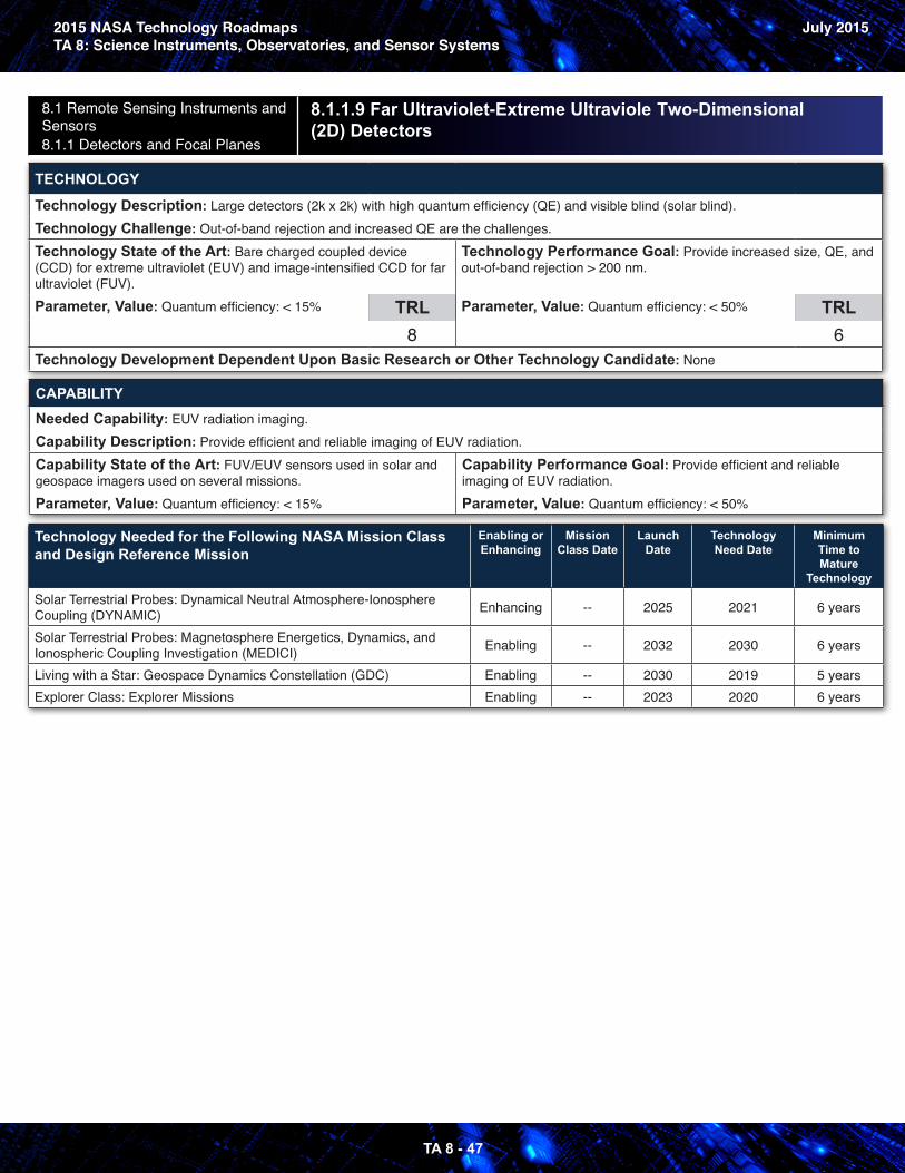
2015 NASA Technology RoadmapsTA 8: Science Instruments, Observatories, and Sensor Systems
July 2015
TA 8 - 47
8.1 Remote Sensing Instruments and Sensors 8.1.1 Detectors and Focal Planes
8.1.1.9 Far Ultraviolet-Extreme Ultraviole Two-Dimensional (2D) Detectors
TECHNOLOGY
Technology Description: Large detectors (2k x 2k) with high quantum efficiency (QE) and visible blind (solar blind).Technology Challenge: Out-of-band rejection and increased QE are the challenges.Technology State of the Art: Bare charged coupled device (CCD) for extreme ultraviolet (EUV) and image-intensified CCD for far ultraviolet (FUV).Parameter, Value: Quantum efficiency: < 15% TRL
8
Technology Performance Goal: Provide increased size, QE, and out-of-band rejection > 200 nm.
Parameter, Value: Quantum efficiency: < 50% TRL6
Technology Development Dependent Upon Basic Research or Other Technology Candidate: None
CAPABILITYNeeded Capability: EUV radiation imaging.Capability Description: Provide efficient and reliable imaging of EUV radiation.Capability State of the Art: FUV/EUV sensors used in solar and geospace imagers used on several missions. Parameter, Value: Quantum efficiency: < 15%
Capability Performance Goal: Provide efficient and reliable imaging of EUV radiation.Parameter, Value: Quantum efficiency: < 50%
Technology Needed for the Following NASA Mission Class and Design Reference Mission
Enabling or Enhancing
Mission Class Date
Launch Date
Technology Need Date
Minimum Time to Mature
Technology
Solar Terrestrial Probes: Dynamical Neutral Atmosphere-Ionosphere Coupling (DYNAMIC) Enhancing -- 2025 2021 6 years
Solar Terrestrial Probes: Magnetosphere Energetics, Dynamics, and Ionospheric Coupling Investigation (MEDICI) Enabling -- 2032 2030 6 years
Living with a Star: Geospace Dynamics Constellation (GDC) Enabling -- 2030 2019 5 yearsExplorer Class: Explorer Missions Enabling -- 2023 2020 6 years
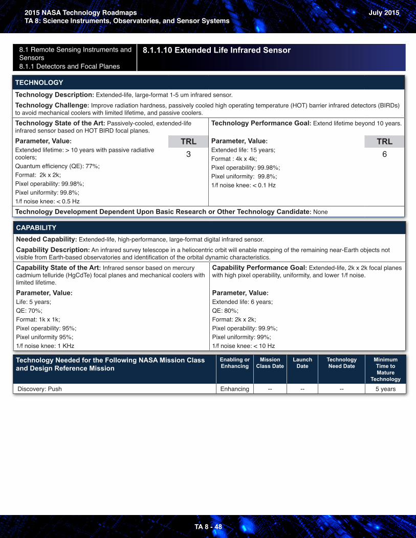
2015 NASA Technology RoadmapsTA 8: Science Instruments, Observatories, and Sensor Systems
July 2015
TA 8 - 48
8.1 Remote Sensing Instruments and Sensors 8.1.1 Detectors and Focal Planes
8.1.1.10 Extended Life Infrared Sensor
TECHNOLOGY
Technology Description: Extended-life, large-format 1-5 um infrared sensor.Technology Challenge: Improve radiation hardness, passively cooled high operating temperature (HOT) barrier infrared detectors (BIRDs) to avoid mechanical coolers with limited lifetime, and passive coolers.Technology State of the Art: Passively-cooled, extended-life infrared sensor based on HOT BIRD focal planes.Parameter, Value: Extended lifetime: > 10 years with passive radiative coolers;Quantum efficiency (QE): 77%;Format: 2k x 2k;Pixel operability: 99.98%;Pixel uniformity: 99.8%;1/f noise knee: < 0.5 Hz
TRL3
Technology Performance Goal: Extend lifetime beyond 10 years.
Parameter, Value: Extended life: 15 years;Format : 4k x 4k;Pixel operability: 99.98%;Pixel uniformity: 99.8%;1/f noise knee: < 0.1 Hz
TRL6
Technology Development Dependent Upon Basic Research or Other Technology Candidate: None
CAPABILITYNeeded Capability: Extended-life, high-performance, large-format digital infrared sensor.Capability Description: An infrared survey telescope in a heliocentric orbit will enable mapping of the remaining near-Earth objects not visible from Earth-based observatories and identification of the orbital dynamic characteristics.Capability State of the Art: Infrared sensor based on mercury cadmium telluride (HgCdTe) focal planes and mechanical coolers with limited lifetime. Parameter, Value: Life: 5 years;QE: 70%;Format: 1k x 1k;Pixel operability: 95%;Pixel uniformity 95%;1/f noise knee: 1 KHz
Capability Performance Goal: Extended-life, 2k x 2k focal planes with high pixel operability, uniformity, and lower 1/f noise.
Parameter, Value: Extended life: 6 years;QE: 80%;Format: 2k x 2k;Pixel operability: 99.9%;Pixel uniformity: 99%;1/f noise knee: < 10 Hz
Technology Needed for the Following NASA Mission Class and Design Reference Mission
Enabling or Enhancing
Mission Class Date
Launch Date
Technology Need Date
Minimum Time to Mature
Technology
Discovery: Push Enhancing -- -- -- 5 years
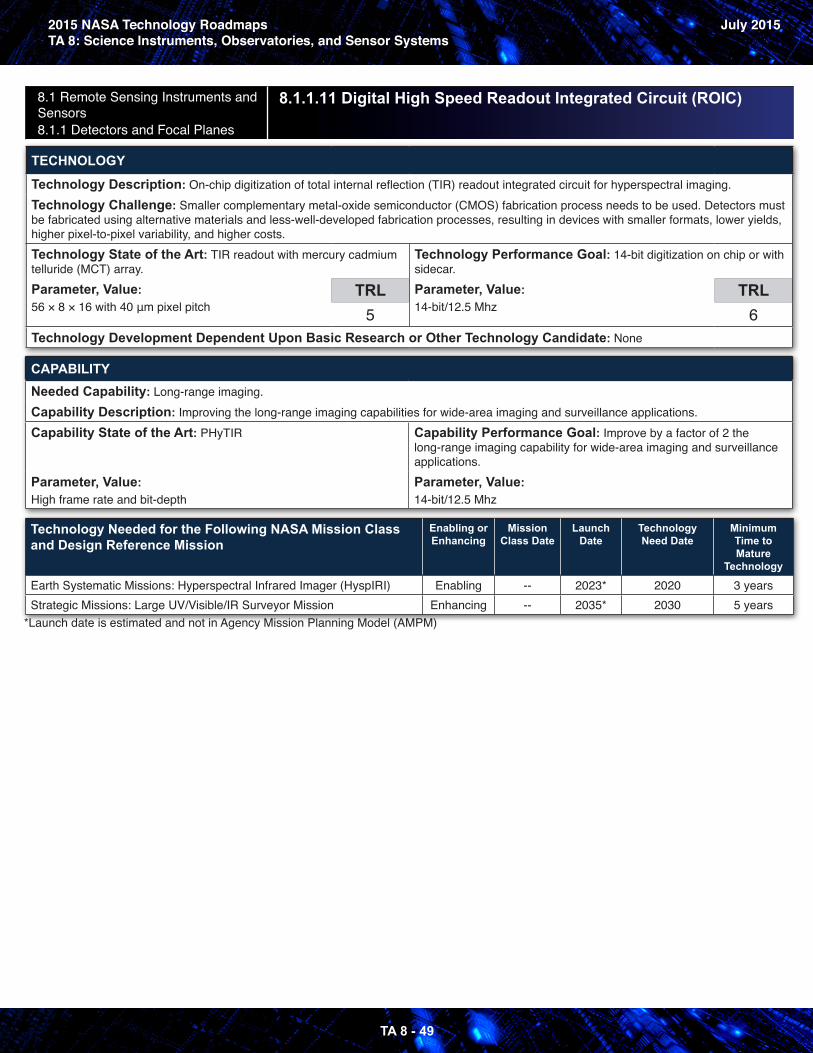
2015 NASA Technology RoadmapsTA 8: Science Instruments, Observatories, and Sensor Systems
July 2015
TA 8 - 49
8.1 Remote Sensing Instruments and Sensors 8.1.1 Detectors and Focal Planes
8.1.1.11 Digital High Speed Readout Integrated Circuit (ROIC)
TECHNOLOGY
Technology Description: On-chip digitization of total internal reflection (TIR) readout integrated circuit for hyperspectral imaging.Technology Challenge: Smaller complementary metal-oxide semiconductor (CMOS) fabrication process needs to be used. Detectors must be fabricated using alternative materials and less-well-developed fabrication processes, resulting in devices with smaller formats, lower yields, higher pixel-to-pixel variability, and higher costs.Technology State of the Art: TIR readout with mercury cadmium telluride (MCT) array.Parameter, Value: 56 × 8 × 16 with 40 μm pixel pitch
TRL5
Technology Performance Goal: 14-bit digitization on chip or with sidecar.Parameter, Value: 14-bit/12.5 Mhz
TRL6
Technology Development Dependent Upon Basic Research or Other Technology Candidate: None
CAPABILITYNeeded Capability: Long-range imaging.Capability Description: Improving the long-range imaging capabilities for wide-area imaging and surveillance applications.Capability State of the Art: PHyTIR
Parameter, Value: High frame rate and bit-depth
Capability Performance Goal: Improve by a factor of 2 the long-range imaging capability for wide-area imaging and surveillance applications.Parameter, Value: 14-bit/12.5 Mhz
Technology Needed for the Following NASA Mission Class and Design Reference Mission
Enabling or Enhancing
Mission Class Date
Launch Date
Technology Need Date
Minimum Time to Mature
Technology
Earth Systematic Missions: Hyperspectral Infrared Imager (HyspIRI) Enabling -- 2023* 2020 3 yearsStrategic Missions: Large UV/Visible/IR Surveyor Mission Enhancing -- 2035* 2030 5 years
*Launch date is estimated and not in Agency Mission Planning Model (AMPM)
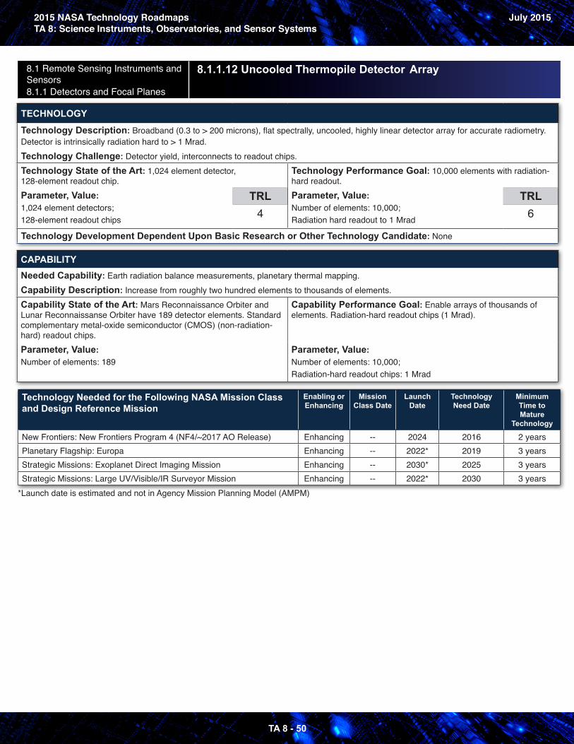
2015 NASA Technology RoadmapsTA 8: Science Instruments, Observatories, and Sensor Systems
July 2015
TA 8 - 50
8.1 Remote Sensing Instruments and Sensors 8.1.1 Detectors and Focal Planes
8.1.1.12 Uncooled Thermopile Detector Array
TECHNOLOGY
Technology Description: Broadband (0.3 to > 200 microns), flat spectrally, uncooled, highly linear detector array for accurate radiometry.Detector is intrinsically radiation hard to > 1 Mrad.Technology Challenge: Detector yield, interconnects to readout chips.
Technology State of the Art: 1,024 element detector, 128-element readout chip.Parameter, Value: 1,024 element detectors;128-element readout chips
TRL4
Technology Performance Goal: 10,000 elements with radiation-hard readout.Parameter, Value: Number of elements: 10,000;Radiation hard readout to 1 Mrad
TRL6
Technology Development Dependent Upon Basic Research or Other Technology Candidate: None
CAPABILITYNeeded Capability: Earth radiation balance measurements, planetary thermal mapping.Capability Description: Increase from roughly two hundred elements to thousands of elements.Capability State of the Art: Mars Reconnaissance Orbiter and Lunar Reconnaissanse Orbiter have 189 detector elements. Standard complementary metal-oxide semiconductor (CMOS) (non-radiation-hard) readout chips. Parameter, Value: Number of elements: 189
Capability Performance Goal: Enable arrays of thousands of elements. Radiation-hard readout chips (1 Mrad).
Parameter, Value: Number of elements: 10,000;Radiation-hard readout chips: 1 Mrad
Technology Needed for the Following NASA Mission Class and Design Reference Mission
Enabling or Enhancing
Mission Class Date
Launch Date
Technology Need Date
Minimum Time to Mature
Technology
New Frontiers: New Frontiers Program 4 (NF4/~2017 AO Release) Enhancing -- 2024 2016 2 yearsPlanetary Flagship: Europa Enhancing -- 2022* 2019 3 yearsStrategic Missions: Exoplanet Direct Imaging Mission Enhancing -- 2030* 2025 3 yearsStrategic Missions: Large UV/Visible/IR Surveyor Mission Enhancing -- 2022* 2030 3 years
*Launch date is estimated and not in Agency Mission Planning Model (AMPM)
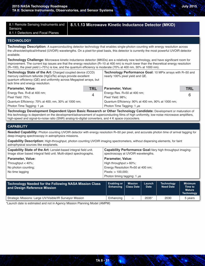
2015 NASA Technology RoadmapsTA 8: Science Instruments, Observatories, and Sensor Systems
July 2015
TA 8 - 51
8.1 Remote Sensing Instruments and Sensors 8.1.1 Detectors and Focal Planes
8.1.1.13 Microwave Kinetic Inductance Detector (MKID)
TECHNOLOGY
Technology Description: A superconducting detector technology that enables single-photon counting with energy resolution across the ultraviolet/optical/infrared (UVOIR) wavelengths. On a pixel-for-pixel basis, this detector is currently the most powerful UVOIR detector available. Technology Challenge: Microwave kinetic inductance detector (MKIDs) are a relatively new technology, and have significant room for improvement. The current top issues are that the energy resolution (R~10 at 400 nm) is much lower than the theoretical energy resolution (R~100), the pixel yield (~75%) is low, and the quantum efficiency is moderate (70% at 400 nm, 30% at 1000 nm). Technology State of the Art: Charged coupled device (CCD) mercury cadmium telluride (HgCdTe) arrays provide excellent quantum efficiency (QE) and uniformity across Megapixel arrays, but lack time and energy resolution.Parameter, Value: Energy Res. R=8 at 400 nm;Pixel Yield: 75%;Quantum Efficiency: 70% at 400; nm, 30% at 1000 nm;Photon Time Tagging: 1 μs
TRL4
Technology Performance Goal: 10 MPix arrays with R~50 and nearly 100% pixel yield and QE.
Parameter, Value: Energy Res. R=50 at 400 nm;Pixel Yield: 98%;Quantum Efficiency: 90% at 400 nm, 90% at 1000 nm;Photon Time Tagging: 1 μs
TRL6
Technology Development Dependent Upon Basic Research or Other Technology Candidate: Development or maturation of this technology is dependent on the development/advancement of superconducting films of high uniformity, low-noise microwave amplifiers, high-speed and signal-to-noise ratio (SNR) analog-to-digital converters, and 4 K space cryocoolers.
CAPABILITYNeeded Capability: Photon counting UVOIR detector with energy resolution R~50 per pixel, and accurate photon time of arrival tagging for deep-imaging spectroscopy in astrophysics missions.Capability Description: High-throughput, photon counting UVOIR imaging spectrometers, without dispersing elements, for faint astrophysical sources like exoplanets. Capability State of the Art: Lenslet-based integral field unit. Image slicer based integral field unit. Multi-object spectrographs. Parameter, Value: Throughput < 40%;No photon counting;No time tagging
Capability Performance Goal:Very high throughput imaging-spectroscopy at UVOIR wavelengths.Parameter, Value: High throughput > 60%;Energy Resolution R=50 at 400 nm;Pixels: > 100,000; Photon timing tagging: 1 μs
Technology Needed for the Following NASA Mission Class and Design Reference Mission
Enabling or Enhancing
Mission Class Date
Launch Date
Technology Need Date
Minimum Time to Mature
Technology
Strategic Missions: Large UV/Visible/IR Surveyor Mission Enhancing -- 2035* 2030 5 years*Launch date is estimated and not in Agency Mission Planning Model (AMPM)
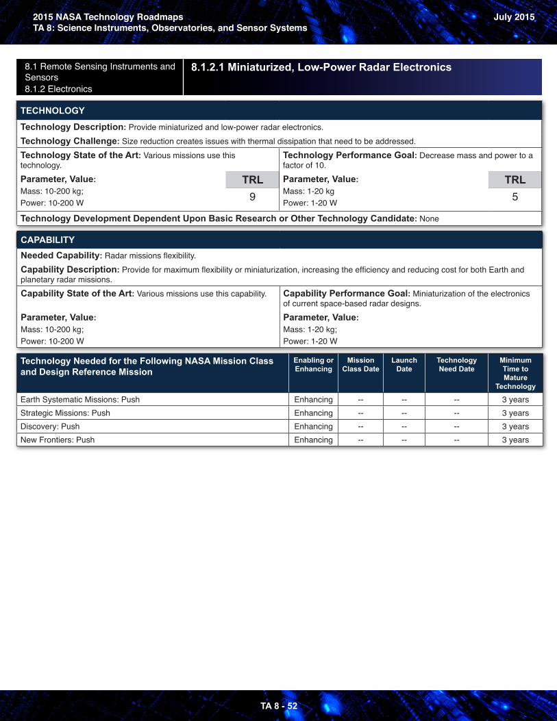
2015 NASA Technology RoadmapsTA 8: Science Instruments, Observatories, and Sensor Systems
July 2015
TA 8 - 52
8.1 Remote Sensing Instruments and Sensors 8.1.2 Electronics
8.1.2.1 Miniaturized, Low-Power Radar Electronics
TECHNOLOGY
Technology Description: Provide miniaturized and low-power radar electronics. Technology Challenge: Size reduction creates issues with thermal dissipation that need to be addressed. Technology State of the Art: Various missions use this technology.Parameter, Value: Mass: 10-200 kg;Power: 10-200 W
TRL9
Technology Performance Goal: Decrease mass and power to a factor of 10.Parameter, Value: Mass: 1-20 kg Power: 1-20 W
TRL5
Technology Development Dependent Upon Basic Research or Other Technology Candidate: None
CAPABILITYNeeded Capability: Radar missions flexibility.Capability Description: Provide for maximum flexibility or miniaturization, increasing the efficiency and reducing cost for both Earth and planetary radar missions. Capability State of the Art: Various missions use this capability.
Parameter, Value: Mass: 10-200 kg;Power: 10-200 W
Capability Performance Goal: Miniaturization of the electronics of current space-based radar designs.Parameter, Value: Mass: 1-20 kg;Power: 1-20 W
Technology Needed for the Following NASA Mission Class and Design Reference Mission
Enabling or Enhancing
Mission Class Date
Launch Date
Technology Need Date
Minimum Time to Mature
Technology
Earth Systematic Missions: Push Enhancing -- -- -- 3 yearsStrategic Missions: Push Enhancing -- -- -- 3 yearsDiscovery: Push Enhancing -- -- -- 3 yearsNew Frontiers: Push Enhancing -- -- -- 3 years
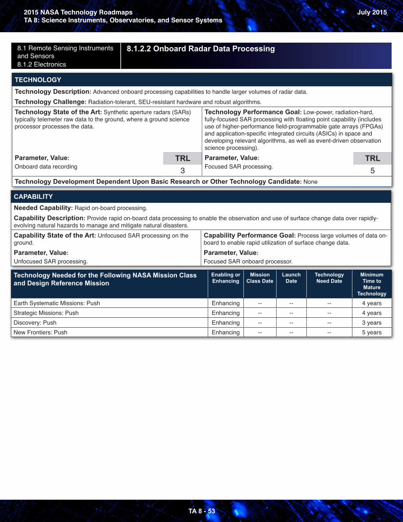
2015 NASA Technology RoadmapsTA 8: Science Instruments, Observatories, and Sensor Systems
July 2015
TA 8 - 53
8.1 Remote Sensing Instruments and Sensors 8.1.2 Electronics
8.1.2.2 Onboard Radar Data Processing
TECHNOLOGY
Technology Description: Advanced onboard processing capabilities to handle larger volumes of radar data. Technology Challenge: Radiation-tolerant, SEU-resistant hardware and robust algorithms. Technology State of the Art: Synthetic aperture radars (SARs) typically telemeter raw data to the ground, where a ground science processor processes the data.
Parameter, Value: Onboard data recording
TRL3
Technology Performance Goal: Low-power, radiation-hard, fully-focused SAR processing with floating point capability (includes use of higher-performance field-programmable gate arrays (FPGAs) and application-specific integrated circuits (ASICs) in space and developing relevant algorithms, as well as event-driven observation science processing).Parameter, Value: Focused SAR processing.
TRL5
Technology Development Dependent Upon Basic Research or Other Technology Candidate: None
CAPABILITYNeeded Capability: Rapid on-board processing.Capability Description: Provide rapid on-board data processing to enable the observation and use of surface change data over rapidly-evolving natural hazards to manage and mitigate natural disasters. Capability State of the Art: Unfocused SAR processing on the ground. Parameter, Value: Unfocused SAR processing.
Capability Performance Goal: Process large volumes of data on-board to enable rapid utilization of surface change data.Parameter, Value: Focused SAR onboard processor.
Technology Needed for the Following NASA Mission Class and Design Reference Mission
Enabling or Enhancing
Mission Class Date
Launch Date
Technology Need Date
Minimum Time to Mature
Technology
Earth Systematic Missions: Push Enhancing -- -- -- 4 yearsStrategic Missions: Push Enhancing -- -- -- 4 yearsDiscovery: Push Enhancing -- -- -- 3 yearsNew Frontiers: Push Enhancing -- -- -- 5 years
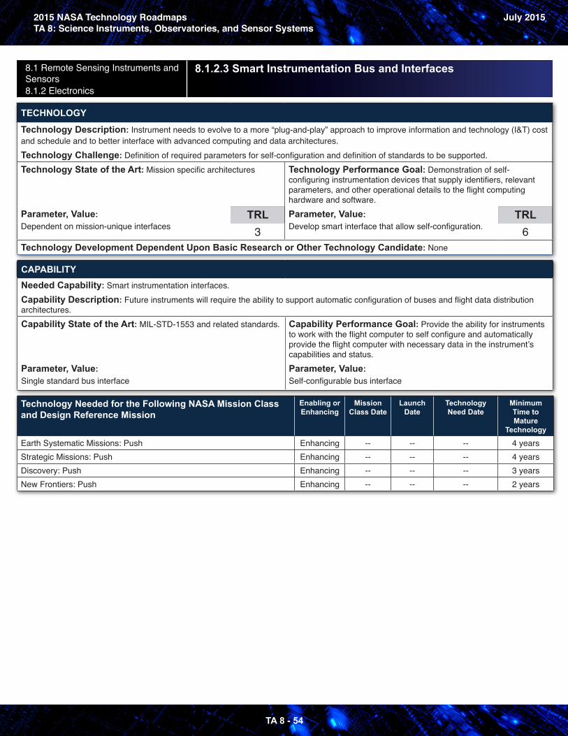
2015 NASA Technology RoadmapsTA 8: Science Instruments, Observatories, and Sensor Systems
July 2015
TA 8 - 54
8.1 Remote Sensing Instruments and Sensors 8.1.2 Electronics
8.1.2.3 Smart Instrumentation Bus and Interfaces
TECHNOLOGY
Technology Description: Instrument needs to evolve to a more “plug-and-play” approach to improve information and technology (I&T) cost and schedule and to better interface with advanced computing and data architectures. Technology Challenge: Definition of required parameters for self-configuration and definition of standards to be supported. Technology State of the Art: Mission specific architectures
Parameter, Value: Dependent on mission-unique interfaces
TRL3
Technology Performance Goal: Demonstration of self-configuring instrumentation devices that supply identifiers, relevant parameters, and other operational details to the flight computing hardware and software.Parameter, Value: Develop smart interface that allow self-configuration.
TRL6
Technology Development Dependent Upon Basic Research or Other Technology Candidate: None
CAPABILITYNeeded Capability: Smart instrumentation interfaces.Capability Description: Future instruments will require the ability to support automatic configuration of buses and flight data distribution architectures. Capability State of the Art: MIL-STD-1553 and related standards.
Parameter, Value: Single standard bus interface
Capability Performance Goal: Provide the ability for instruments to work with the flight computer to self configure and automatically provide the flight computer with necessary data in the instrument’s capabilities and status.Parameter, Value: Self-configurable bus interface
Technology Needed for the Following NASA Mission Class and Design Reference Mission
Enabling or Enhancing
Mission Class Date
Launch Date
Technology Need Date
Minimum Time to Mature
Technology
Earth Systematic Missions: Push Enhancing -- -- -- 4 yearsStrategic Missions: Push Enhancing -- -- -- 4 yearsDiscovery: Push Enhancing -- -- -- 3 yearsNew Frontiers: Push Enhancing -- -- -- 2 years
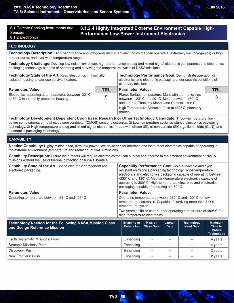
2015 NASA Technology RoadmapsTA 8: Science Instruments, Observatories, and Sensor Systems
July 2015
TA 8 - 55
8.1 Remote Sensing Instruments and Sensors 8.1.2 Electronics
8.1.2.4 Highly Integrated Extreme Environment Capable High- Performance Low-Power Instrument Electronics
TECHNOLOGY
Technology Description: High-performance and low-power instrument electronics that can operate at extremely low (cryogenics) or high temperatures, and over wide temperature ranges. Technology Challenge: Develop low-noise, low-power, high-performance analog and mixed-signal electronic components and electronics packaging technology capable of operating and surviving the temperature cycles of NASA missions.
Technology State of the Art: Keep electronics in thermally-isolated housing and/or use survival heaters.
Parameter, Value: Electronics operating at temperatures between -30° C to 50° C in thermally-protected housing.
TRL9
Technology Performance Goal: Demonstrate operation of electronics and electronic packaging under specific conditions of planetary missions.Parameter, Value: Planet Surface temperature: Mars with thermal cycles between -120° C and 20° C, Moon between -180° C and 120° C, Titan, Icy Moons and Comets -180° C.High Temperature: Venus surface at 480° C, planetary probes
TRL3
Technology Development Dependent Upon Basic Research or Other Technology Candidate: 1) Low-temperature, low-power complementary metal-oxide semiconductor (CMOS) sensor electronics, 2) Low-temperature cycle resistance electronics packaging technology, 3) High-temperature analog and mixed-signal electronics (made with silicon (Si), silicon carbide (SiC), gallium nitride (GaN)) and electronics packaging technology.
CAPABILITYNeeded Capability: Highly miniaturized, ultra-low-power, low-noise sensor interface and instrument electronics capable of operating in the extreme environment (temperature and radiation) of NASA missions.Capability Description: Future instruments will require electronics that can survive and operate in the ambient environment of NASA missions without the use of thermal protection or survival heaters. Capability State of the Art: Space electronic component and electronic packaging.
Parameter, Value: Operating temperature between -55° C and 125° C.
Capability Performance Goal: Cold-survivable and cycle resistant electronics packaging technology. Wide-temperature electronics and electronics packaging capable of operating between -230° C and 120° C. Medium-temperature electronics capable of operating to 300° C. High-temperature electronic and electronics packaging capable of operating at 480° C.Parameter, Value: Operating temperature between -230° C and 120° C for low-temperature electronics. Capable of surviving more than 5,000 temperature cycles. Two years of life or better under operating temperature of 480° C for high-temperature electronics.
Technology Needed for the Following NASA Mission Class and Design Reference Mission
Enabling or Enhancing
Mission Class Date
Launch Date
Technology Need Date
Minimum Time to Mature
Technology
Earth Systematic Missions: Push Enhancing -- -- -- 4 yearsStrategic Missions: Push Enhancing -- -- -- 4 yearsDiscovery: Push Enhancing -- -- -- 3 yearsNew Frontiers: Push Enhancing -- -- -- 2 years
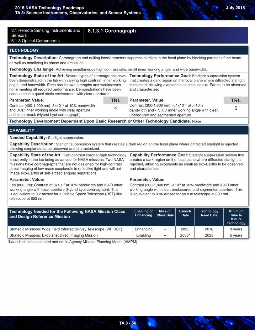
2015 NASA Technology RoadmapsTA 8: Science Instruments, Observatories, and Sensor Systems
July 2015
TA 8 - 56
8.1 Remote Sensing Instruments and Sensors 8.1.3 Optical Components
8.1.3.1 Coronagraph
TECHNOLOGY
Technology Description: Coronagraph and nulling interferometers suppress starlight in the focal plane by blocking portions of the beam, as well as modifying its phase and amplitude. Technology Challenge: Achieving simultaneous high contrast ratio, small inner working angle, and wide bandwidth. Technology State of the Art: Several types of coronagraphs have been demonstrated in the lab with varying high contrast, inner working angle, and bandwidth. Each has its own strengths and weaknesses none meeting all required performance. Demonstrations have been conducted in a quasi-static environment with clear apertures.Parameter, Value: Contrast (400-1,000 nm): 3×10⁻¹⁰ at 10% bandwidth and 3λ/D inner working angle with clear aperture and linear mask (Hybrid Lyot coronagraph)
TRL4
Technology Performance Goal: Starlight suppression system that creates a dark region on the focal plane where diffracted starlight is rejected, allowing exoplanets as small as exo-Earths to be observed and characterized.
Parameter, Value: Contrast (300-1,800 nm): < 1x10⁻¹⁰ at > 10% bandwidth and < 3 λ/D inner working angle with clear, unobscured and segmented aperture
TRL5
Technology Development Dependent Upon Basic Research or Other Technology Candidate: None
CAPABILITYNeeded Capability: Starlight suppression.Capability Description: Starlight suppression system that creates a dark region on the focal plane where diffracted starlight is rejected, allowing exoplanets to be observed and characterized. Capability State of the Art: High-contrast coronagraph technology is currently in the lab being advanced for NASA missions. Two NASA missions have coronagraphs that are not designed for high-contrast direct imaging of low-mass exoplanets in reflective light and will not image exo-Earths at sub-arcsec angular separations. Parameter, Value: Lab (800 μm): Contrast of 3x10⁻¹⁰ at 10% bandwidth and 3 λ/D inner working angle with clear aperture (Hybrid Lyot coronagraph). This is equivalent to 0.2 arcsec for a Hubble Space Telescope (HST)-like telescope at 800 nm.
Capability Performance Goal: Starlight suppression system that creates a dark region on the focal plane where diffracted starlight is rejected, allowing exoplanets as small as exo-Earths to be observed and characterized.
Parameter, Value: Contrast (300-1,800 nm) ≤ 10-9 at 10% bandwidth and 3 λ/D inner working angle with clear, unobscured and segmented aperture. This is equivalent to 0.06 arcsec for an 8 m telescope at 800 nm.
Technology Needed for the Following NASA Mission Class and Design Reference Mission
Enabling or Enhancing
Mission Class Date
Launch Date
Technology Need Date
Minimum Time to Mature
Technology
Strategic Missions: Wide Field Infrared Survey Telescope (WFIRST) Enhancing -- 2025 2018 3 yearsStrategic Missions: Exoplanet Direct Imaging Mission Enabling -- 2030* 2025 5 years
*Launch date is estimated and not in Agency Mission Planning Model (AMPM)
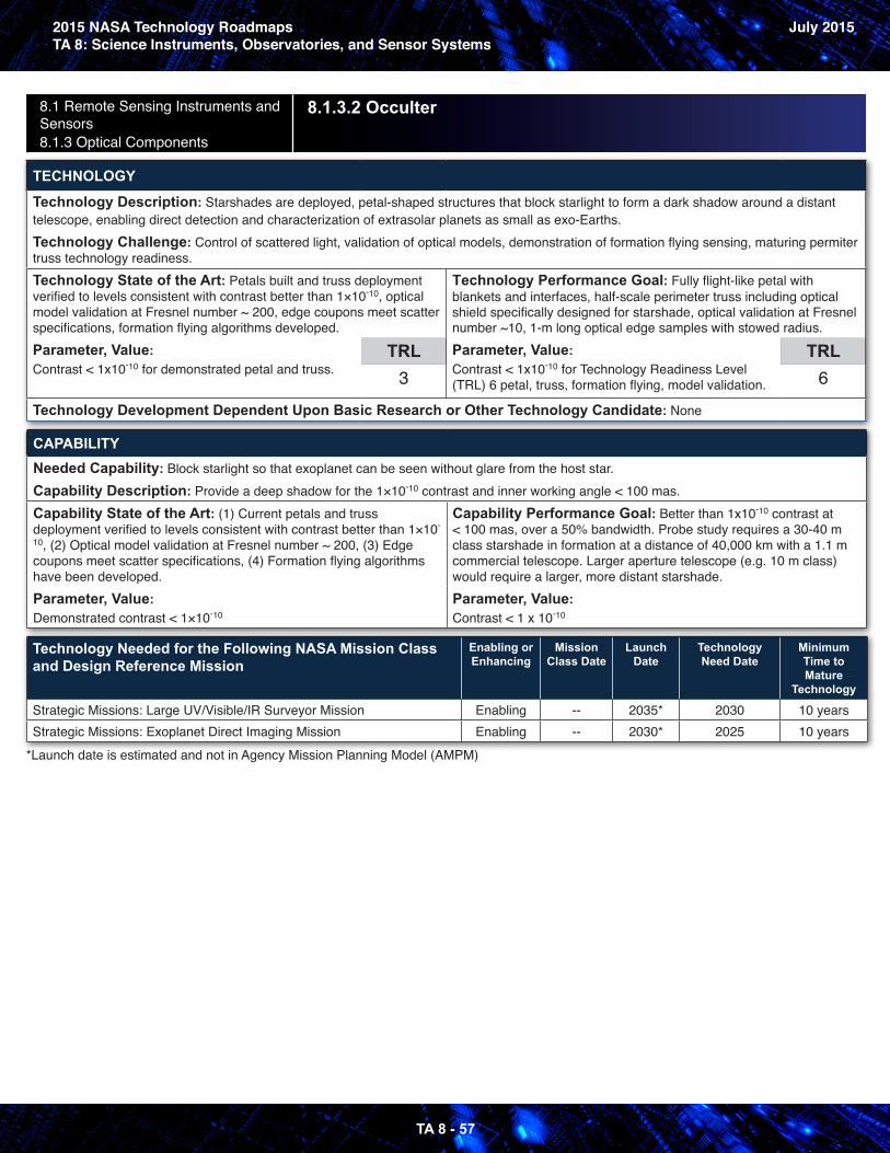
2015 NASA Technology RoadmapsTA 8: Science Instruments, Observatories, and Sensor Systems
July 2015
TA 8 - 57
8.1 Remote Sensing Instruments and Sensors 8.1.3 Optical Components
8.1.3.2 Occulter
TECHNOLOGY
Technology Description: Starshades are deployed, petal-shaped structures that block starlight to form a dark shadow around a distant telescope, enabling direct detection and characterization of extrasolar planets as small as exo-Earths. Technology Challenge: Control of scattered light, validation of optical models, demonstration of formation flying sensing, maturing permiter truss technology readiness. Technology State of the Art: Petals built and truss deployment verified to levels consistent with contrast better than 1×10⁻¹⁰, optical model validation at Fresnel number ~ 200, edge coupons meet scatter specifications, formation flying algorithms developed. Parameter, Value: Contrast < 1x10⁻¹⁰ for demonstrated petal and truss.
TRL3
Technology Performance Goal: Fully flight-like petal with blankets and interfaces, half-scale perimeter truss including optical shield specifically designed for starshade, optical validation at Fresnel number ~10, 1-m long optical edge samples with stowed radius. Parameter, Value: Contrast < 1x10⁻¹⁰ for Technology Readiness Level (TRL) 6 petal, truss, formation flying, model validation.
TRL6
Technology Development Dependent Upon Basic Research or Other Technology Candidate: None
CAPABILITYNeeded Capability: Block starlight so that exoplanet can be seen without glare from the host star.Capability Description: Provide a deep shadow for the 1×10⁻¹⁰ contrast and inner working angle < 100 mas. Capability State of the Art: (1) Current petals and truss deployment verified to levels consistent with contrast better than 1×10-
10, (2) Optical model validation at Fresnel number ~ 200, (3) Edge coupons meet scatter specifications, (4) Formation flying algorithms have been developed. Parameter, Value: Demonstrated contrast < 1×10⁻¹⁰
Capability Performance Goal: Better than 1x10⁻¹⁰ contrast at < 100 mas, over a 50% bandwidth. Probe study requires a 30-40 m class starshade in formation at a distance of 40,000 km with a 1.1 m commercial telescope. Larger aperture telescope (e.g. 10 m class) would require a larger, more distant starshade.Parameter, Value: Contrast < 1 x 10⁻¹⁰
Technology Needed for the Following NASA Mission Class and Design Reference Mission
Enabling or Enhancing
Mission Class Date
Launch Date
Technology Need Date
Minimum Time to Mature
Technology
Strategic Missions: Large UV/Visible/IR Surveyor Mission Enabling -- 2035* 2030 10 yearsStrategic Missions: Exoplanet Direct Imaging Mission Enabling -- 2030* 2025 10 years
*Launch date is estimated and not in Agency Mission Planning Model (AMPM)
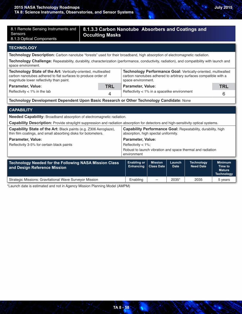
2015 NASA Technology RoadmapsTA 8: Science Instruments, Observatories, and Sensor Systems
July 2015
TA 8 - 58
8.1 Remote Sensing Instruments and Sensors 8.1.3 Optical Components
8.1.3.3 Carbon Nanotube Absorbers and Coatings and Occulting Masks
TECHNOLOGY
Technology Description: Carbon nanotube “forests” used for their broadband, high absorption of electromagnetic radiation. Technology Challenge: Repeatability, durability, characterization (performance, conductivity, radiation), and compatibility with launch and space environment. Technology State of the Art: Vertically-oriented, multiwalled carbon nanotubes adhered to flat surfaces to produce order of magnitude lower reflectivity than paint. Parameter, Value: Reflectivity < 1% in the lab
TRL4
Technology Performance Goal: Vertically-oriented, multiwalled carbon nanotubes adhered to arbitrary surfaces compatible with a space environment. Parameter, Value: Reflectivity < 1% in a spacelike environment
TRL6
Technology Development Dependent Upon Basic Research or Other Technology Candidate: None
CAPABILITYNeeded Capability: Broadband absorption of electromagnetic radiation.Capability Description: Provide straylight suppression and radiation absorption for detectors and high-sensitivity optical systems.Capability State of the Art: Black paints (e.g. Z306 Aeroglaze), thin film coatings, and small absorbing disks for bolometers. Parameter, Value: Reflectivity 3-5% for certain black paints
Capability Performance Goal: Repeatability, durability, high absorption, high spectal uniformity.Parameter, Value: Reflectivity < 1%;Robust to launch vibration and space thermal and radiation environment
Technology Needed for the Following NASA Mission Class and Design Reference Mission
Enabling or Enhancing
Mission Class Date
Launch Date
Technology Need Date
Minimum Time to Mature
Technology
Strategic Missions: Gravitational Wave Surveyor Mission Enabling -- 2035* 2035 5 years*Launch date is estimated and not in Agency Mission Planning Model (AMPM)
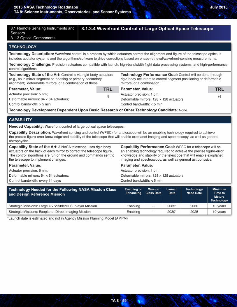
2015 NASA Technology RoadmapsTA 8: Science Instruments, Observatories, and Sensor Systems
July 2015
TA 8 - 59
8.1 Remote Sensing Instruments and Sensors 8.1.3 Optical Components
8.1.3.4 Wavefront Control of Large Optical Space Telescope
TECHNOLOGY
Technology Description: Wavefront control is a process by which actuators correct the alignment and figure of the telescope optics. It includes acutator systems and the algorithms/software to drive corrections based on phase-retrieval/wavefront-sensing measurements.Technology Challenge: Precision actuators compatible with launch, high-bandwidth flight data processing systems, and high-performance control algorithms. Technology State of the Art: Control is via rigid-body actuators (e.g., as in mirror segment co-phasing or primary-secondary alignment), deformable mirrors, or a combination of these. Parameter, Value: Actuator precision: 5 nm;Deformable mirrors: 64 × 64 actuators;Control bandwidth: > 5 min
TRL4
Technology Performance Goal: Control will be done through rigid-body actuators to control segment positioning or deformable mirrors, or a combination. Parameter, Value: Actuator precision: 1 pm;Deformable mirrors: 128 × 128 actuators; Control bandwidth: < 5 min
TRL6
Technology Development Dependent Upon Basic Research or Other Technology Candidate: None
CAPABILITYNeeded Capability: Wavefront control of large optical space telescopes.Capability Description: Wavefront sensing and control (WFSC) for a telescope will be an enabling technology required to achieve the precise figure-error knowledge and stability of the telescope that will enable exoplanet imaging and spectroscopy, as well as general astrophysics.Capability State of the Art: A NASA telescope uses rigid body actuators on the back of each mirror to correct the telescope figure. The control algorithms are run on the ground and commands sent to the telescope to implement changes. Parameter, Value: Actuator precision: 5 nm;Deformable mirrors: 64 × 64 actuators;Control bandwidth: every 14 days
Capability Performance Goal: WFSC for a telescope will be an enabling technology required to achieve the precise figure-error knowledge and stability of the telescope that will enable exoplanet imaging and spectroscopy, as well as general astrophysics. Parameter, Value: Actuator precision: 1 pm;Deformable mirrors: 128 × 128 actuators;Control bandwidth: < 5 min
Technology Needed for the Following NASA Mission Class and Design Reference Mission
Enabling or Enhancing
Mission Class Date
Launch Date
Technology Need Date
Minimum Time to Mature
Technology
Strategic Missions: Large UV/Visible/IR Surveyor Mission Enabling -- 2035* 2030 10 yearsStrategic Missions: Exoplanet Direct Imaging Mission Enabling -- 2030* 2025 10 years
*Launch date is estimated and not in Agency Mission Planning Model (AMPM)
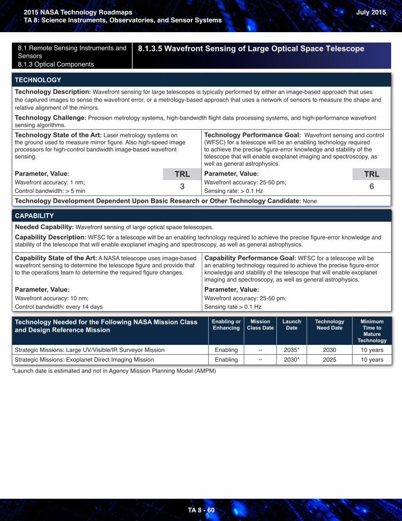
2015 NASA Technology RoadmapsTA 8: Science Instruments, Observatories, and Sensor Systems
July 2015
TA 8 - 60
8.1 Remote Sensing Instruments and Sensors 8.1.3 Optical Components
8.1.3.5 Wavefront Sensing of Large Optical Space Telescope
TECHNOLOGY
Technology Description: Wavefront sensing for large telescopes is typically performed by either an image-based approach that uses the captured images to sense the wavefront error, or a metrology-based approach that uses a network of sensors to measure the shape and relative alignment of the mirrors.Technology Challenge: Precision metrology systems, high-bandwidth flight data processing systems, and high-performance wavefront sensing algorithms. Technology State of the Art: Laser metrology systems on the ground used to measure mirror figure. Also high-speed image processors for high-control bandwidth image-based wavefront sensing.
Parameter, Value: Wavefront accuracy: 1 nm;Control bandwidth: > 5 min
TRL3
Technology Performance Goal: Wavefront sensing and control (WFSC) for a telescope will be an enabling technology required to achieve the precise figure-error knowledge and stability of the telescope that will enable exoplanet imaging and spectroscopy, as well as general astrophysics. Parameter, Value: Wavefront accuracy: 25-50 pm;Sensing rate: > 0.1 Hz
TRL6
Technology Development Dependent Upon Basic Research or Other Technology Candidate: None
CAPABILITYNeeded Capability: Wavefront sensing of large optical space telescopes.Capability Description: WFSC for a telescope will be an enabling technology required to achieve the precise figure-error knowledge and stability of the telescope that will enable exoplanet imaging and spectroscopy, as well as general astrophysics.
Capability State of the Art: A NASA telescope uses image-based wavefront sensing to determine the telescope figure and provide that to the operations team to determine the required figure changes.
Parameter, Value: Wavefront accuracy: 10 nm;Control bandwidth: every 14 days
Capability Performance Goal: WFSC for a telescope will be an enabling technology required to achieve the precise figure-error knowledge and stability of the telescope that will enable exoplanet imaging and spectroscopy, as well as general astrophysics. Parameter, Value: Wavefront accuracy: 25-50 pm;Sensing rate > 0.1 Hz
Technology Needed for the Following NASA Mission Class and Design Reference Mission
Enabling or Enhancing
Mission Class Date
Launch Date
Technology Need Date
Minimum Time to Mature
Technology
Strategic Missions: Large UV/Visible/IR Surveyor Mission Enabling -- 2035* 2030 10 yearsStrategic Missions: Exoplanet Direct Imaging Mission Enabling -- 2030* 2025 10 years
*Launch date is estimated and not in Agency Mission Planning Model (AMPM)
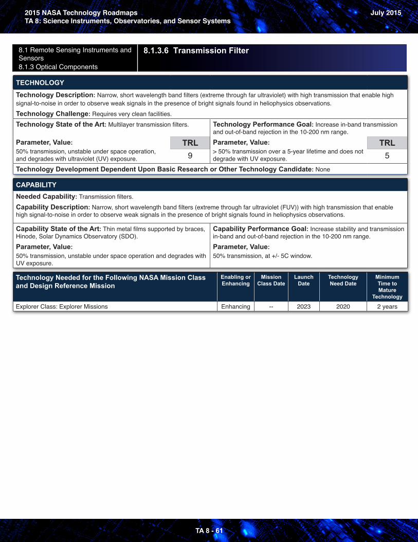
2015 NASA Technology RoadmapsTA 8: Science Instruments, Observatories, and Sensor Systems
July 2015
TA 8 - 61
8.1 Remote Sensing Instruments and Sensors 8.1.3 Optical Components
8.1.3.6 Transmission Filter
TECHNOLOGY
Technology Description: Narrow, short wavelength band filters (extreme through far ultraviolet) with high transmission that enable high signal-to-noise in order to observe weak signals in the presence of bright signals found in heliophysics observations.Technology Challenge: Requires very clean facilities. Technology State of the Art: Multilayer transmission filters.
Parameter, Value: 50% transmission, unstable under space operation, and degrades with ultraviolet (UV) exposure.
TRL9
Technology Performance Goal: Increase in-band transmission and out-of-band rejection in the 10-200 nm range. Parameter, Value: > 50% transmission over a 5-year lifetime and does not degrade with UV exposure.
TRL5
Technology Development Dependent Upon Basic Research or Other Technology Candidate: None
CAPABILITYNeeded Capability: Transmission filters.Capability Description: Narrow, short wavelength band filters (extreme through far ultraviolet (FUV)) with high transmission that enable high signal-to-noise in order to observe weak signals in the presence of bright signals found in heliophysics observations.
Capability State of the Art: Thin metal films supported by braces, Hinode, Solar Dynamics Observatory (SDO). Parameter, Value: 50% transmission, unstable under space operation and degrades with UV exposure.
Capability Performance Goal: Increase stability and transmission in-band and out-of-band rejection in the 10-200 nm range. Parameter, Value: 50% transmission, at +/- 5C window.
Technology Needed for the Following NASA Mission Class and Design Reference Mission
Enabling or Enhancing
Mission Class Date
Launch Date
Technology Need Date
Minimum Time to Mature
Technology
Explorer Class: Explorer Missions Enhancing -- 2023 2020 2 years
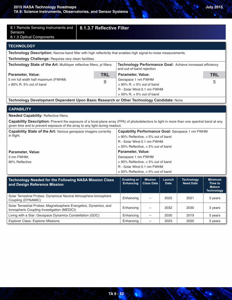
2015 NASA Technology RoadmapsTA 8: Science Instruments, Observatories, and Sensor Systems
July 2015
TA 8 - 62
8.1 Remote Sensing Instruments and Sensors 8.1.3 Optical Components
8.1.3.7 Reflective Filter
TECHNOLOGY
Technology Description: Narrow-band filter with high reflectivity that enables high signal-to-noise measurements.Technology Challenge: Requires very clean facilities. Technology State of the Art: Multilayer reflective filters, pi filters.
Parameter, Value: 5 nm full width half maximum (FWHM)> 80% R, 5% out of band
TRL9
Technology Performance Goal: Achieve increased efficiency and out-of-band rejection. Parameter, Value: Geospace 1 nm FWHM> 90% R, < 5% out of band R - Solar Wind 0.1 nm FWHM> 50% R, < 5% out of band
TRL5
Technology Development Dependent Upon Basic Research or Other Technology Candidate: None
CAPABILITYNeeded Capability: Reflective filters.Capability Description: Prevent the exposure of a focal-plane array (FPA) of photodetectors to light in more than one spectral band at any given time and to prevent exposure of the array to any light during readout. Capability State of the Art: Various geospace imagers currently in flight.
Parameter, Value: 5 nm FWHM;80% Reflective
Capability Performance Goal: Geospace 1 nm FWHM > 90% Reflective, < 5% out of band R - Solar Wind 0.1 nm FWHM> 50% Reflective, < 5% out of bandParameter, Value: Geospace 1 nm FWHM> 90% Reflective, < 5% out of band R - Solar Wind 0.1 nm FWHM> 50% Reflective, < 5% out of band
Technology Needed for the Following NASA Mission Class and Design Reference Mission
Enabling or Enhancing
Mission Class Date
Launch Date
Technology Need Date
Minimum Time to Mature
Technology
Solar Terrestrial Probes: Dynamical Neutral Atmosphere-Ionosphere Coupling (DYNAMIC) Enhancing -- 2025 2021 3 years
Solar Terrestrial Probes: Magnetosphere Energetics, Dynamics, and Ionospheric Coupling Investigation (MEDICI) Enhancing -- 2032 2030 3 years
Living with a Star: Geospace Dynamics Constellation (GDC) Enhancing -- 2030 2019 3 yearsExplorer Class: Explorer Missions Enhancing -- 2023 2020 3 years
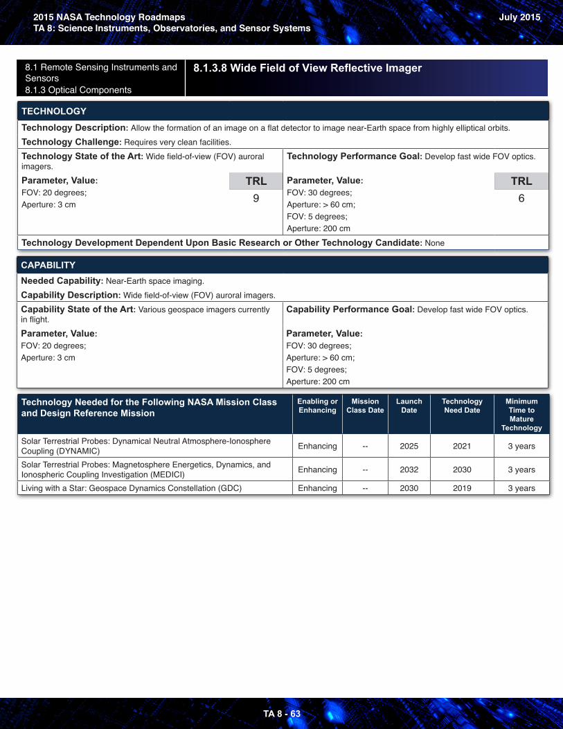
2015 NASA Technology RoadmapsTA 8: Science Instruments, Observatories, and Sensor Systems
July 2015
TA 8 - 63
8.1 Remote Sensing Instruments and Sensors 8.1.3 Optical Components
8.1.3.8 Wide Field of View Reflective Imager
TECHNOLOGY
Technology Description: Allow the formation of an image on a flat detector to image near-Earth space from highly elliptical orbits.Technology Challenge: Requires very clean facilities. Technology State of the Art: Wide field-of-view (FOV) auroral imagers.Parameter, Value: FOV: 20 degrees;Aperture: 3 cm
TRL9
Technology Performance Goal: Develop fast wide FOV optics.
Parameter, Value: FOV: 30 degrees;Aperture: > 60 cm; FOV: 5 degrees;Aperture: 200 cm
TRL6
Technology Development Dependent Upon Basic Research or Other Technology Candidate: None
CAPABILITYNeeded Capability: Near-Earth space imaging.Capability Description: Wide field-of-view (FOV) auroral imagers.Capability State of the Art: Various geospace imagers currently in flight.Parameter, Value: FOV: 20 degrees;Aperture: 3 cm
Capability Performance Goal: Develop fast wide FOV optics.
Parameter, Value: FOV: 30 degrees;Aperture: > 60 cm; FOV: 5 degrees;Aperture: 200 cm
Technology Needed for the Following NASA Mission Class and Design Reference Mission
Enabling or Enhancing
Mission Class Date
Launch Date
Technology Need Date
Minimum Time to Mature
Technology
Solar Terrestrial Probes: Dynamical Neutral Atmosphere-Ionosphere Coupling (DYNAMIC) Enhancing -- 2025 2021 3 years
Solar Terrestrial Probes: Magnetosphere Energetics, Dynamics, and Ionospheric Coupling Investigation (MEDICI) Enhancing -- 2032 2030 3 years
Living with a Star: Geospace Dynamics Constellation (GDC) Enhancing -- 2030 2019 3 years
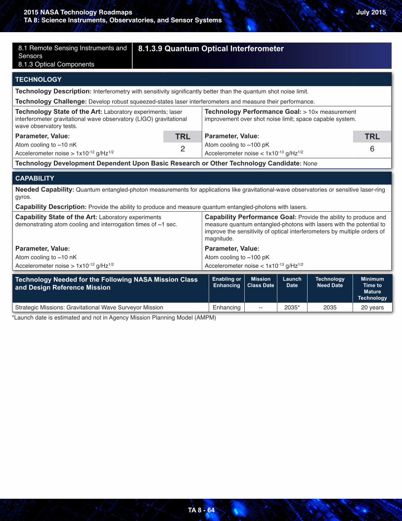
2015 NASA Technology RoadmapsTA 8: Science Instruments, Observatories, and Sensor Systems
July 2015
TA 8 - 64
8.1 Remote Sensing Instruments and Sensors 8.1.3 Optical Components
8.1.3.9 Quantum Optical Interferometer
TECHNOLOGY
Technology Description: Interferometry with sensitivity significantly better than the quantum shot noise limit.Technology Challenge: Develop robust squeezed-states laser interferometers and measure their performance.Technology State of the Art: Laboratory experiments; laser interferometer gravitational wave observatory (LIGO) gravitational wave observatory tests.Parameter, Value: Atom cooling to ~10 nKAccelerometer noise > 1x10-12 g/Hz1/2
TRL2
Technology Performance Goal: > 10× measurement improvement over shot noise limit; space capable system.
Parameter, Value: Atom cooling to ~100 pKAccelerometer noise < 1x10-13 g/Hz1/2
TRL6
Technology Development Dependent Upon Basic Research or Other Technology Candidate: None
CAPABILITYNeeded Capability: Quantum entangled-photon measurements for applications like gravitational-wave observatories or sensitive laser-ring gyros.Capability Description: Provide the ability to produce and measure quantum entangled-photons with lasers.Capability State of the Art: Laboratory experiments demonstrating atom cooling and interrogation times of ~1 sec.
Parameter, Value: Atom cooling to ~10 nKAccelerometer noise > 1x10-12 g/Hz1/2
Capability Performance Goal: Provide the ability to produce and measure quantum entangled-photons with lasers with the potential to improve the sensitivity of optical interferometers by multiple orders of magnitude.Parameter, Value: Atom cooling to ~100 pKAccelerometer noise < 1x10-13 g/Hz1/2
Technology Needed for the Following NASA Mission Class and Design Reference Mission
Enabling or Enhancing
Mission Class Date
Launch Date
Technology Need Date
Minimum Time to Mature
Technology
Strategic Missions: Gravitational Wave Surveyor Mission Enhancing -- 2035* 2035 20 years*Launch date is estimated and not in Agency Mission Planning Model (AMPM)
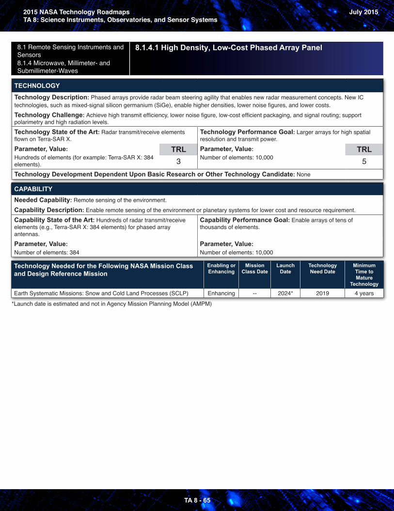
2015 NASA Technology RoadmapsTA 8: Science Instruments, Observatories, and Sensor Systems
July 2015
TA 8 - 65
8.1 Remote Sensing Instruments and Sensors 8.1.4 Microwave, Millimeter- and Submillimeter-Waves
8.1.4.1 High Density, Low-Cost Phased Array Panel
TECHNOLOGY
Technology Description: Phased arrays provide radar beam steering agility that enables new radar measurement concepts. New IC technologies, such as mixed-signal silicon germanium (SiGe), enable higher densities, lower noise figures, and lower costs.Technology Challenge: Achieve high transmit efficiency, lower noise figure, low-cost efficient packaging, and signal routing; support polarimetry and high radiation levels.Technology State of the Art: Radar transmit/receive elements flown on Terra-SAR X. Parameter, Value: Hundreds of elements (for example: Terra-SAR X: 384 elements).
TRL3
Technology Performance Goal: Larger arrays for high spatial resolution and transmit power.Parameter, Value: Number of elements: 10,000
TRL5
Technology Development Dependent Upon Basic Research or Other Technology Candidate: None
CAPABILITYNeeded Capability: Remote sensing of the environment.Capability Description: Enable remote sensing of the environment or planetary systems for lower cost and resource requirement.Capability State of the Art: Hundreds of radar transmit/receive elements (e.g., Terra-SAR X: 384 elements) for phased array antennas.Parameter, Value: Number of elements: 384
Capability Performance Goal: Enable arrays of tens of thousands of elements.
Parameter, Value: Number of elements: 10,000
Technology Needed for the Following NASA Mission Class and Design Reference Mission
Enabling or Enhancing
Mission Class Date
Launch Date
Technology Need Date
Minimum Time to Mature
Technology
Earth Systematic Missions: Snow and Cold Land Processes (SCLP) Enhancing -- 2024* 2019 4 years
*Launch date is estimated and not in Agency Mission Planning Model (AMPM)
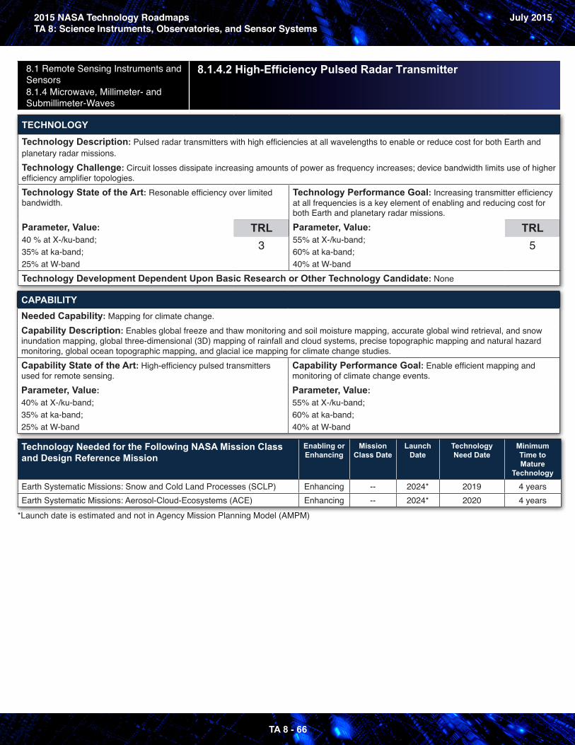
2015 NASA Technology RoadmapsTA 8: Science Instruments, Observatories, and Sensor Systems
July 2015
TA 8 - 66
8.1 Remote Sensing Instruments and Sensors 8.1.4 Microwave, Millimeter- and Submillimeter-Waves
8.1.4.2 High-Efficiency Pulsed Radar Transmitter
TECHNOLOGY
Technology Description: Pulsed radar transmitters with high efficiencies at all wavelengths to enable or reduce cost for both Earth and planetary radar missions.Technology Challenge: Circuit losses dissipate increasing amounts of power as frequency increases; device bandwidth limits use of higher efficiency amplifier topologies.Technology State of the Art: Resonable efficiency over limited bandwidth.
Parameter, Value: 40 % at X-/ku-band; 35% at ka-band; 25% at W-band
TRL3
Technology Performance Goal: Increasing transmitter efficiency at all frequencies is a key element of enabling and reducing cost for both Earth and planetary radar missions.Parameter, Value: 55% at X-/ku-band;60% at ka-band; 40% at W-band
TRL5
Technology Development Dependent Upon Basic Research or Other Technology Candidate: None
CAPABILITYNeeded Capability: Mapping for climate change.Capability Description: Enables global freeze and thaw monitoring and soil moisture mapping, accurate global wind retrieval, and snow inundation mapping, global three-dimensional (3D) mapping of rainfall and cloud systems, precise topographic mapping and natural hazard monitoring, global ocean topographic mapping, and glacial ice mapping for climate change studies.Capability State of the Art: High-efficiency pulsed transmitters used for remote sensing.Parameter, Value: 40% at X-/ku-band; 35% at ka-band; 25% at W-band
Capability Performance Goal: Enable efficient mapping and monitoring of climate change events.Parameter, Value: 55% at X-/ku-band;60% at ka-band; 40% at W-band
Technology Needed for the Following NASA Mission Class and Design Reference Mission
Enabling or Enhancing
Mission Class Date
Launch Date
Technology Need Date
Minimum Time to Mature
Technology
Earth Systematic Missions: Snow and Cold Land Processes (SCLP) Enhancing -- 2024* 2019 4 yearsEarth Systematic Missions: Aerosol-Cloud-Ecosystems (ACE) Enhancing -- 2024* 2020 4 years
*Launch date is estimated and not in Agency Mission Planning Model (AMPM)
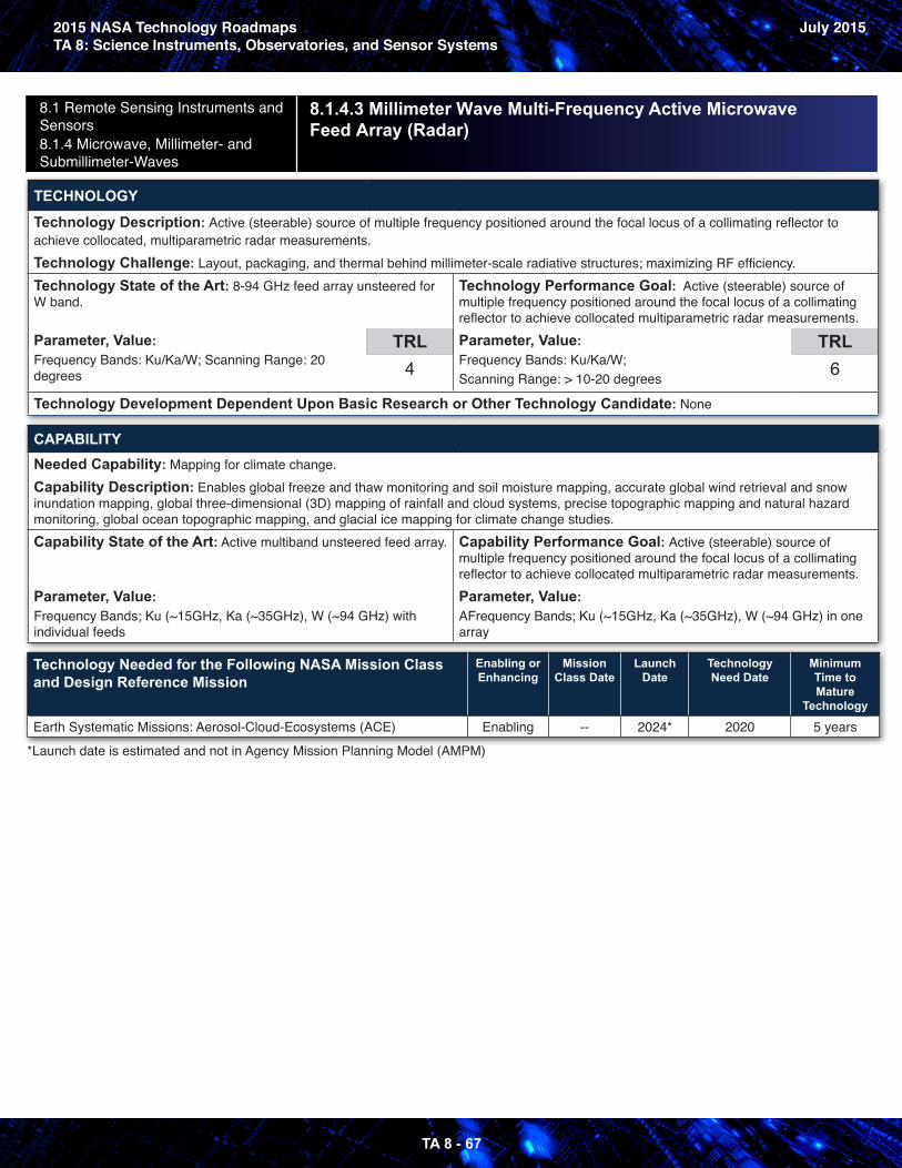
2015 NASA Technology RoadmapsTA 8: Science Instruments, Observatories, and Sensor Systems
July 2015
TA 8 - 67
8.1 Remote Sensing Instruments and Sensors 8.1.4 Microwave, Millimeter- and Submillimeter-Waves
8.1.4.3 Millimeter Wave Multi-Frequency Active Microwave Feed Array (Radar)
TECHNOLOGY
Technology Description: Active (steerable) source of multiple frequency positioned around the focal locus of a collimating reflector to achieve collocated, multiparametric radar measurements.Technology Challenge: Layout, packaging, and thermal behind millimeter-scale radiative structures; maximizing RF efficiency.Technology State of the Art: 8-94 GHz feed array unsteered for W band.
Parameter, Value: Frequency Bands: Ku/Ka/W; Scanning Range: 20 degrees
TRL4
Technology Performance Goal: Active (steerable) source of multiple frequency positioned around the focal locus of a collimating reflector to achieve collocated multiparametric radar measurements.Parameter, Value: Frequency Bands: Ku/Ka/W;Scanning Range: > 10-20 degrees
TRL6
Technology Development Dependent Upon Basic Research or Other Technology Candidate: None
CAPABILITYNeeded Capability: Mapping for climate change.Capability Description: Enables global freeze and thaw monitoring and soil moisture mapping, accurate global wind retrieval and snow inundation mapping, global three-dimensional (3D) mapping of rainfall and cloud systems, precise topographic mapping and natural hazard monitoring, global ocean topographic mapping, and glacial ice mapping for climate change studies.Capability State of the Art: Active multiband unsteered feed array.
Parameter, Value: Frequency Bands; Ku (~15GHz, Ka (~35GHz), W (~94 GHz) with individual feeds
Capability Performance Goal: Active (steerable) source of multiple frequency positioned around the focal locus of a collimating reflector to achieve collocated multiparametric radar measurements.Parameter, Value: AFrequency Bands; Ku (~15GHz, Ka (~35GHz), W (~94 GHz) in one array
Technology Needed for the Following NASA Mission Class and Design Reference Mission
Enabling or Enhancing
Mission Class Date
Launch Date
Technology Need Date
Minimum Time to Mature
Technology
Earth Systematic Missions: Aerosol-Cloud-Ecosystems (ACE) Enabling -- 2024* 2020 5 years
*Launch date is estimated and not in Agency Mission Planning Model (AMPM)
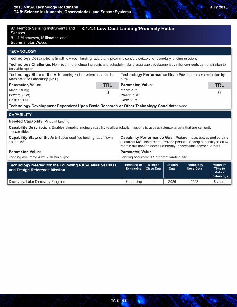
2015 NASA Technology RoadmapsTA 8: Science Instruments, Observatories, and Sensor Systems
July 2015
TA 8 - 68
8.1 Remote Sensing Instruments and Sensors 8.1.4 Microwave, Millimeter- and Submillimeter-Waves
8.1.4.4 Low-Cost Landing/Proximity Radar
TECHNOLOGY
Technology Description: Small, low-cost, landing radars and proximity sensors suitable for planetary landing missions.Technology Challenge: Non-recurring engineering costs and schedule risks discourage development by mission-needs demonstration to be viable option.Technology State of the Art: Landing radar system used for the Mars Science Laboratory (MSL).Parameter, Value: Mass: 29 kg; Power: 30 W;Cost: $10 M
TRL3
Technology Performance Goal: Power and mass reduction by 50%.Parameter, Value: Mass: 2 kg;Power: 5 W; Cost: $1 M
TRL6
Technology Development Dependent Upon Basic Research or Other Technology Candidate: None
CAPABILITYNeeded Capability: Pinpoint landing.Capability Description: Enables pinpoint landing capability to allow robotic missions to access science targets that are currently inaccessible.Capability State of the Art: Space-qualified landing radar flown on the MSL.
Parameter, Value: Landing accuracy: 4 km x 10 km ellipse
Capability Performance Goal: Reduce mass, power, and volume of current MSL instrument. Provide pinpoint-landing capability to allow robotic missions to access currently-inaccessible science targets.Parameter, Value: Landing accuracy: 0.1 of target landing site
Technology Needed for the Following NASA Mission Class and Design Reference Mission
Enabling or Enhancing
Mission Class Date
Launch Date
Technology Need Date
Minimum Time to Mature
Technology
Discovery: Later Discovery Program Enhancing -- 2026 2023 8 years
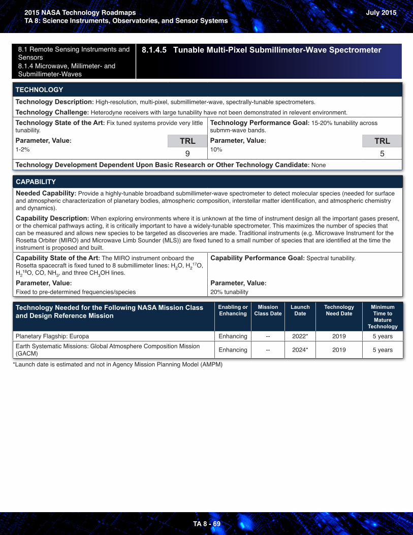
2015 NASA Technology RoadmapsTA 8: Science Instruments, Observatories, and Sensor Systems
July 2015
TA 8 - 69
8.1 Remote Sensing Instruments and Sensors 8.1.4 Microwave, Millimeter- and Submillimeter-Waves
8.1.4.5 Tunable Multi-Pixel Submillimeter-Wave Spectrometer
TECHNOLOGY
Technology Description: High-resolution, multi-pixel, submillimeter-wave, spectrally-tunable spectrometers.Technology Challenge: Heterodyne receivers with large tunability have not been demonstrated in relevent environment.Technology State of the Art: Fix tuned systems provide very little tunability.Parameter, Value: 1-2%
TRL9
Technology Performance Goal: 15-20% tunability across submm-wave bands.Parameter, Value: 10%
TRL5
Technology Development Dependent Upon Basic Research or Other Technology Candidate: None
CAPABILITYNeeded Capability: Provide a highly-tunable broadband submillimeter-wave spectrometer to detect molecular species (needed for surface and atmospheric characterization of planetary bodies, atmospheric composition, interstellar matter identification, and atmospheric chemistry and dynamics).Capability Description: When exploring environments where it is unknown at the time of instrument design all the important gases present, or the chemical pathways acting, it is critically important to have a widely-tunable spectrometer. This maximizes the number of species that can be measured and allows new species to be targeted as discoveries are made. Traditional instruments (e.g. Microwave Instrument for the Rosetta Orbiter (MIRO) and Microwave Limb Sounder (MLS)) are fixed tuned to a small number of species that are identified at the time the instrument is proposed and built.Capability State of the Art: The MIRO instrument onboard the Rosetta spacecraft is fixed tuned to 8 submillimeter lines: H2O, H 17
2 O, H 18
2 O, CO, NH3, and three CH3OH lines.Parameter, Value: Fixed to pre-determined frequencies/species
Capability Performance Goal: Spectral tunability.
Parameter, Value: 20% tunability
Technology Needed for the Following NASA Mission Class and Design Reference Mission
Enabling or Enhancing
Mission Class Date
Launch Date
Technology Need Date
Minimum Time to Mature
Technology
Planetary Flagship: Europa Enhancing -- 2022* 2019 5 yearsEarth Systematic Missions: Global Atmosphere Composition Mission (GACM) Enhancing -- 2024* 2019 5 years
*Launch date is estimated and not in Agency Mission Planning Model (AMPM)
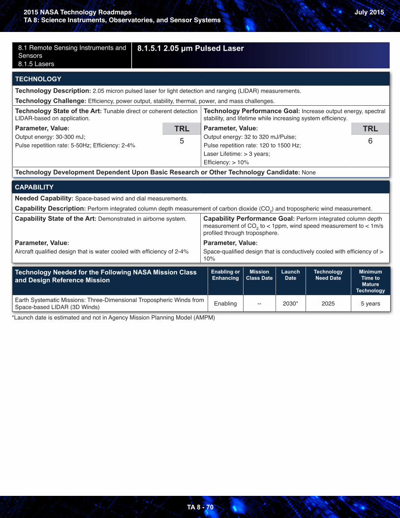
2015 NASA Technology RoadmapsTA 8: Science Instruments, Observatories, and Sensor Systems
July 2015
TA 8 - 70
8.1 Remote Sensing Instruments and Sensors 8.1.5 Lasers
8.1.5.1 2.05 μm Pulsed Laser
TECHNOLOGY
Technology Description: 2.05 micron pulsed laser for light detection and ranging (LIDAR) measurements.Technology Challenge: Efficiency, power output, stability, thermal, power, and mass challenges.Technology State of the Art: Tunable direct or coherent detection LIDAR-based on application.Parameter, Value: Output energy: 30-300 mJ;Pulse repetition rate: 5-50Hz; Efficiency: 2-4%
TRL5
Technology Performance Goal: Increase output energy, spectral stability, and lifetime while increasing system efficiency.Parameter, Value: Output energy: 32 to 320 mJ/Pulse;Pulse repetition rate: 120 to 1500 Hz; Laser Lifetime: > 3 years;Efficiency: > 10%
TRL6
Technology Development Dependent Upon Basic Research or Other Technology Candidate: None
CAPABILITYNeeded Capability: Space-based wind and dial measurements.Capability Description: Perform integrated column depth measurement of carbon dioxide (CO2) and tropospheric wind measurement.Capability State of the Art: Demonstrated in airborne system.
Parameter, Value: Aircraft qualified design that is water cooled with efficiency of 2-4%
Capability Performance Goal: Perform integrated column depth measurement of CO2 to < 1ppm, wind speed measurement to < 1m/s profiled through troposphere.Parameter, Value: Space-qualified design that is conductively cooled with efficiency of > 10%
Technology Needed for the Following NASA Mission Class and Design Reference Mission
Enabling or Enhancing
Mission Class Date
Launch Date
Technology Need Date
Minimum Time to Mature
Technology
Earth Systematic Missions: Three-Dimensional Tropospheric Winds from Space-based LIDAR (3D Winds) Enabling -- 2030* 2025 5 years
*Launch date is estimated and not in Agency Mission Planning Model (AMPM)
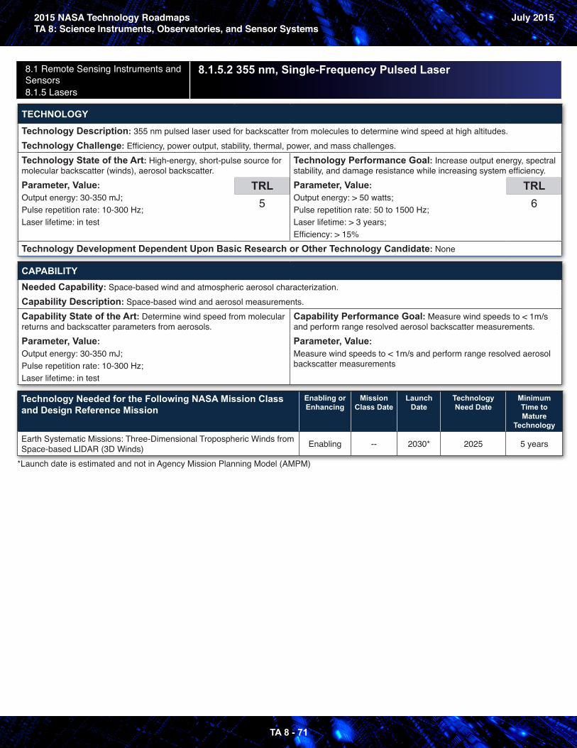
2015 NASA Technology RoadmapsTA 8: Science Instruments, Observatories, and Sensor Systems
July 2015
TA 8 - 71
8.1 Remote Sensing Instruments and Sensors 8.1.5 Lasers
8.1.5.2 355 nm, Single-Frequency Pulsed Laser
TECHNOLOGY
Technology Description: 355 nm pulsed laser used for backscatter from molecules to determine wind speed at high altitudes.Technology Challenge: Efficiency, power output, stability, thermal, power, and mass challenges.Technology State of the Art: High-energy, short-pulse source for molecular backscatter (winds), aerosol backscatter.Parameter, Value: Output energy: 30-350 mJ;Pulse repetition rate: 10-300 Hz;Laser lifetime: in test
TRL5
Technology Performance Goal: Increase output energy, spectral stability, and damage resistance while increasing system efficiency.Parameter, Value: Output energy: > 50 watts;Pulse repetition rate: 50 to 1500 Hz;Laser lifetime: > 3 years;Efficiency: > 15%
TRL6
Technology Development Dependent Upon Basic Research or Other Technology Candidate: None
CAPABILITYNeeded Capability: Space-based wind and atmospheric aerosol characterization.Capability Description: Space-based wind and aerosol measurements.Capability State of the Art: Determine wind speed from molecular returns and backscatter parameters from aerosols.Parameter, Value: Output energy: 30-350 mJ;Pulse repetition rate: 10-300 Hz;Laser lifetime: in test
Capability Performance Goal: Measure wind speeds to < 1m/s and perform range resolved aerosol backscatter measurements.Parameter, Value: Measure wind speeds to < 1m/s and perform range resolved aerosol backscatter measurements
Technology Needed for the Following NASA Mission Class and Design Reference Mission
Enabling or Enhancing
Mission Class Date
Launch Date
Technology Need Date
Minimum Time to Mature
Technology
Earth Systematic Missions: Three-Dimensional Tropospheric Winds from Space-based LIDAR (3D Winds) Enabling -- 2030* 2025 5 years
*Launch date is estimated and not in Agency Mission Planning Model (AMPM)
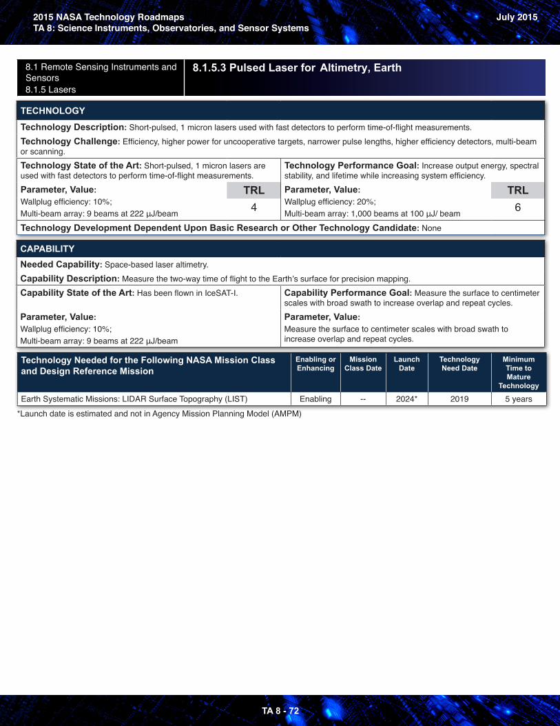
2015 NASA Technology RoadmapsTA 8: Science Instruments, Observatories, and Sensor Systems
July 2015
TA 8 - 72
8.1 Remote Sensing Instruments and Sensors 8.1.5 Lasers
8.1.5.3 Pulsed Laser for Altimetry, Earth
TECHNOLOGY
Technology Description: Short-pulsed, 1 micron lasers used with fast detectors to perform time-of-flight measurements.Technology Challenge: Efficiency, higher power for uncooperative targets, narrower pulse lengths, higher efficiency detectors, multi-beam or scanning.Technology State of the Art: Short-pulsed, 1 micron lasers are used with fast detectors to perform time-of-flight measurements.Parameter, Value: Wallplug efficiency: 10%;Multi-beam array: 9 beams at 222 μJ/beam
TRL4
Technology Performance Goal: Increase output energy, spectral stability, and lifetime while increasing system efficiency.Parameter, Value: Wallplug efficiency: 20%;Multi-beam array: 1,000 beams at 100 μJ/ beam
TRL6
Technology Development Dependent Upon Basic Research or Other Technology Candidate: None
CAPABILITYNeeded Capability: Space-based laser altimetry.Capability Description: Measure the two-way time of flight to the Earth’s surface for precision mapping.Capability State of the Art: Has been flown in IceSAT-I.
Parameter, Value: Wallplug efficiency: 10%;Multi-beam array: 9 beams at 222 μJ/beam
Capability Performance Goal: Measure the surface to centimeter scales with broad swath to increase overlap and repeat cycles.Parameter, Value: Measure the surface to centimeter scales with broad swath to increase overlap and repeat cycles.
Technology Needed for the Following NASA Mission Class and Design Reference Mission
Enabling or Enhancing
Mission Class Date
Launch Date
Technology Need Date
Minimum Time to Mature
Technology
Earth Systematic Missions: LIDAR Surface Topography (LIST) Enabling -- 2024* 2019 5 years*Launch date is estimated and not in Agency Mission Planning Model (AMPM)
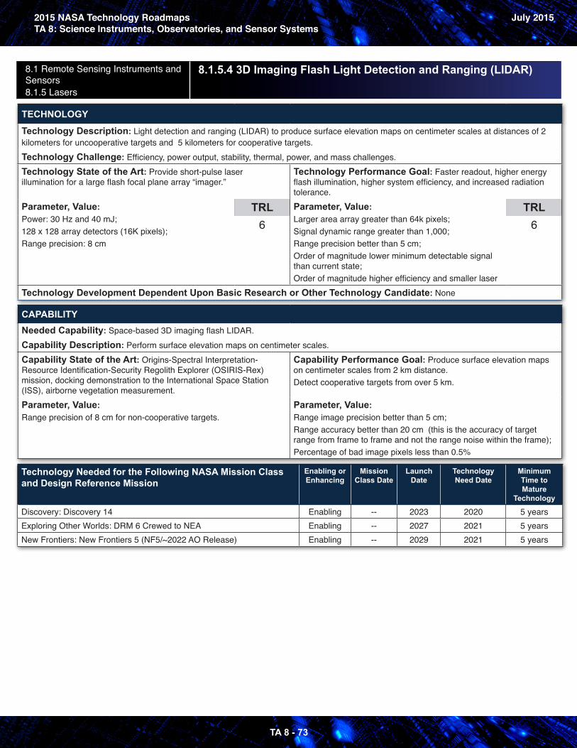
2015 NASA Technology RoadmapsTA 8: Science Instruments, Observatories, and Sensor Systems
July 2015
TA 8 - 73
8.1 Remote Sensing Instruments and Sensors 8.1.5 Lasers
8.1.5.4 3D Imaging Flash Light Detection and Ranging (LIDAR)
TECHNOLOGY
Technology Description: Light detection and ranging (LIDAR) to produce surface elevation maps on centimeter scales at distances of 2 kilometers for uncooperative targets and 5 kilometers for cooperative targets.Technology Challenge: Efficiency, power output, stability, thermal, power, and mass challenges.Technology State of the Art: Provide short-pulse laser illumination for a large flash focal plane array “imager.”
Parameter, Value: Power: 30 Hz and 40 mJ;128 x 128 array detectors (16K pixels);Range precision: 8 cm
TRL6
Technology Performance Goal: Faster readout, higher energy flash illumination, higher system efficiency, and increased radiation tolerance.Parameter, Value: Larger area array greater than 64k pixels;Signal dynamic range greater than 1,000;Range precision better than 5 cm;Order of magnitude lower minimum detectable signal than current state;Order of magnitude higher efficiency and smaller laser
TRL6
Technology Development Dependent Upon Basic Research or Other Technology Candidate: None
CAPABILITYNeeded Capability: Space-based 3D imaging flash LIDAR.Capability Description: Perform surface elevation maps on centimeter scales.Capability State of the Art: Origins-Spectral Interpretation-Resource Identification-Security Regolith Explorer (OSIRIS-Rex) mission, docking demonstration to the International Space Station (ISS), airborne vegetation measurement.Parameter, Value: Range precision of 8 cm for non-cooperative targets.
Capability Performance Goal: Produce surface elevation maps on centimeter scales from 2 km distance.Detect cooperative targets from over 5 km.
Parameter, Value: Range image precision better than 5 cm;Range accuracy better than 20 cm (this is the accuracy of target range from frame to frame and not the range noise within the frame);Percentage of bad image pixels less than 0.5%
Technology Needed for the Following NASA Mission Class and Design Reference Mission
Enabling or Enhancing
Mission Class Date
Launch Date
Technology Need Date
Minimum Time to Mature
Technology
Discovery: Discovery 14 Enabling -- 2023 2020 5 yearsExploring Other Worlds: DRM 6 Crewed to NEA Enabling -- 2027 2021 5 yearsNew Frontiers: New Frontiers 5 (NF5/~2022 AO Release) Enabling -- 2029 2021 5 years
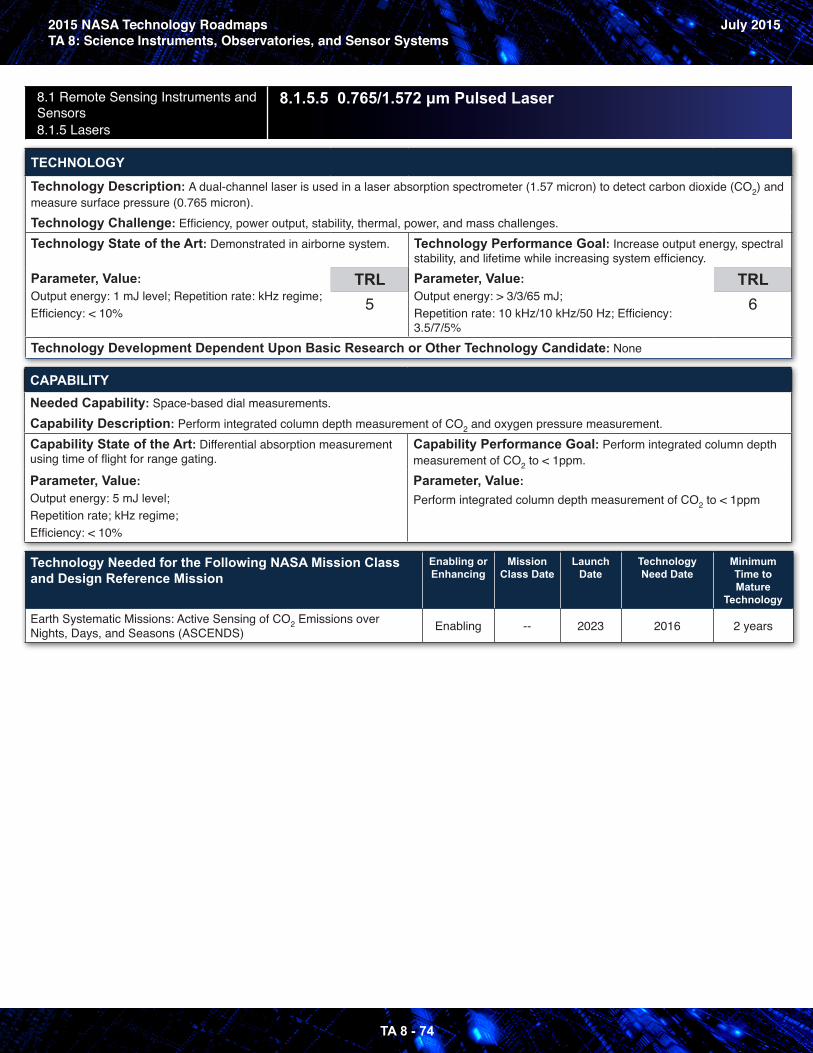
2015 NASA Technology RoadmapsTA 8: Science Instruments, Observatories, and Sensor Systems
July 2015
TA 8 - 74
8.1 Remote Sensing Instruments and Sensors 8.1.5 Lasers
8.1.5.5 0.765/1.572 μm Pulsed Laser
TECHNOLOGY
Technology Description: A dual-channel laser is used in a laser absorption spectrometer (1.57 micron) to detect carbon dioxide (CO2) and measure surface pressure (0.765 micron).Technology Challenge: Efficiency, power output, stability, thermal, power, and mass challenges.Technology State of the Art: Demonstrated in airborne system.
Parameter, Value: Output energy: 1 mJ level; Repetition rate: kHz regime;Efficiency: < 10%
TRL5
Technology Performance Goal: Increase output energy, spectral stability, and lifetime while increasing system efficiency.Parameter, Value: Output energy: > 3/3/65 mJ;Repetition rate: 10 kHz/10 kHz/50 Hz; Efficiency: 3.5/7/5%
TRL6
Technology Development Dependent Upon Basic Research or Other Technology Candidate: None
CAPABILITYNeeded Capability: Space-based dial measurements.Capability Description: Perform integrated column depth measurement of CO2 and oxygen pressure measurement.Capability State of the Art: Differential absorption measurement using time of flight for range gating.
Parameter, Value: Output energy: 5 mJ level;Repetition rate; kHz regime;Efficiency: < 10%
Capability Performance Goal: Perform integrated column depth measurement of CO2 to < 1ppm.Parameter, Value: Perform integrated column depth measurement of CO2 to < 1ppm
Technology Needed for the Following NASA Mission Class and Design Reference Mission
Enabling or Enhancing
Mission Class Date
Launch Date
Technology Need Date
Minimum Time to Mature
Technology
Earth Systematic Missions: Active Sensing of CO2 Emissions over Nights, Days, and Seasons (ASCENDS) Enabling -- 2023 2016 2 years
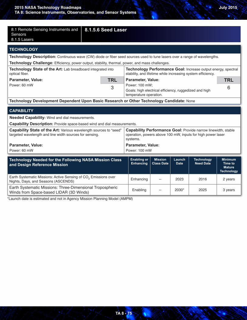
2015 NASA Technology RoadmapsTA 8: Science Instruments, Observatories, and Sensor Systems
July 2015
TA 8 - 75
8.1 Remote Sensing Instruments and Sensors 8.1.5 Lasers
8.1.5.6 Seed Laser
TECHNOLOGY
Technology Description: Continuous wave (CW) diode or fiber seed sources used to tune lasers over a range of wavelengths.Technology Challenge: Efficiency, power output, stability, thermal, power, and mass challenges.Technology State of the Art: Lab breadboard integrated into optical fiber. Parameter, Value: Power: 60 mW
TRL3
Technology Performance Goal: Increase output energy, spectral stability, and lifetime while increasing system efficiency.Parameter, Value: Power: 100 mW; Goals: high electrical efficiency, ruggedized and high temperature operation.
TRL6
Technology Development Dependent Upon Basic Research or Other Technology Candidate: None
CAPABILITYNeeded Capability: Wind and dial measurements.Capability Description: Provide space-based wind and dial measurements.Capability State of the Art: Various wavelength sources to “seed” targeted wavelength and line width sources for sensing.
Capability Performance Goal: Provide narrow linewidth, stable operation, powers above 100 mW, inputs for high power laser systems.
Parameter, Value: Power: 60 mW
Parameter, Value: Power: 100 mW
Technology Needed for the Following NASA Mission Class and Design Reference Mission
Enabling or Enhancing
Mission Class Date
Launch Date
Technology Need Date
Minimum Time to Mature
Technology
Earth Systematic Missions: Active Sensing of CO2 Emissions over Nights, Days, and Seasons (ASCENDS) Enhancing -- 2023 2016 2 years
Earth Systematic Missions: Three-Dimensional Tropospheric Winds from Space-based LIDAR (3D Winds) Enabling -- 2030* 2025 3 years
*Launch date is estimated and not in Agency Mission Planning Model (AMPM)
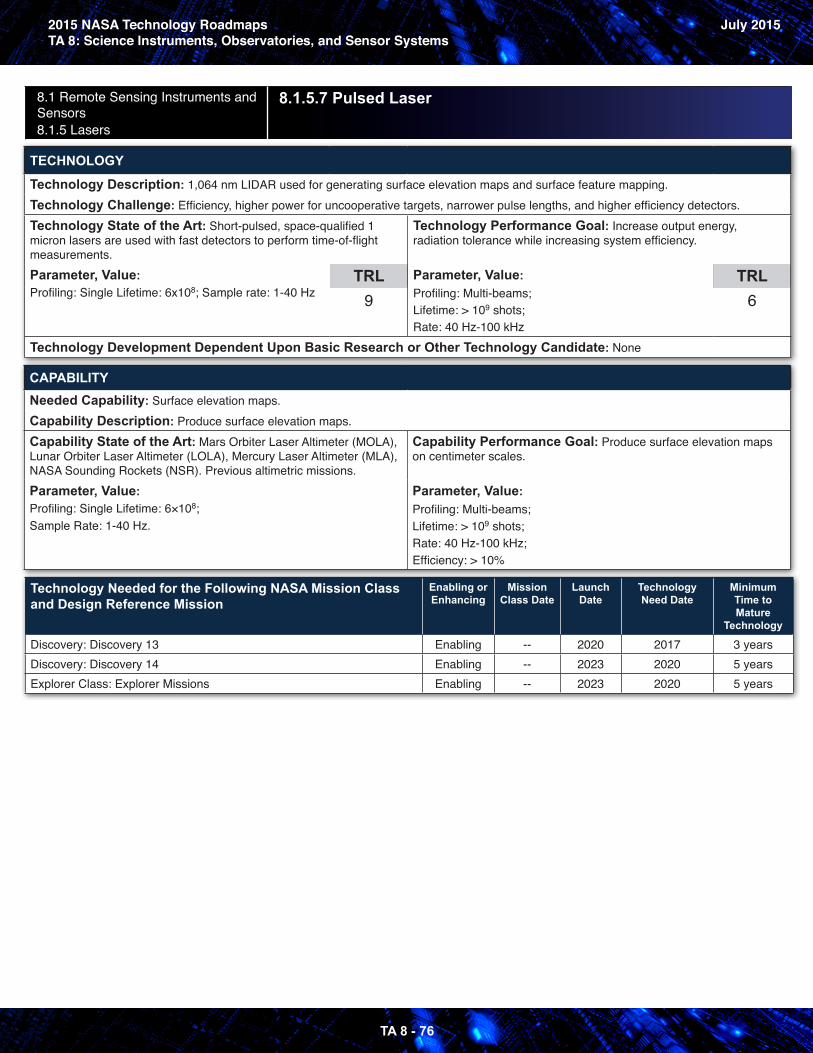
2015 NASA Technology RoadmapsTA 8: Science Instruments, Observatories, and Sensor Systems
July 2015
TA 8 - 76
8.1 Remote Sensing Instruments and Sensors 8.1.5 Lasers
8.1.5.7 Pulsed Laser
TECHNOLOGY
Technology Description: 1,064 nm LIDAR used for generating surface elevation maps and surface feature mapping.Technology Challenge: Efficiency, higher power for uncooperative targets, narrower pulse lengths, and higher efficiency detectors.Technology State of the Art: Short-pulsed, space-qualified 1 micron lasers are used with fast detectors to perform time-of-flight measurements.Parameter, Value: Profiling: Single Lifetime: 6x10⁸; Sample rate: 1-40 Hz
TRL9
Technology Performance Goal: Increase output energy, radiation tolerance while increasing system efficiency.
Parameter, Value: Profiling: Multi-beams; Lifetime: > 109 shots; Rate: 40 Hz-100 kHz
TRL6
Technology Development Dependent Upon Basic Research or Other Technology Candidate: None
CAPABILITYNeeded Capability: Surface elevation maps.Capability Description: Produce surface elevation maps.Capability State of the Art: Mars Orbiter Laser Altimeter (MOLA), Lunar Orbiter Laser Altimeter (LOLA), Mercury Laser Altimeter (MLA), NASA Sounding Rockets (NSR). Previous altimetric missions.Parameter, Value: Profiling: Single Lifetime: 6×10⁸;Sample Rate: 1-40 Hz.
Capability Performance Goal: Produce surface elevation maps on centimeter scales.
Parameter, Value: Profiling: Multi-beams; Lifetime: > 109 shots; Rate: 40 Hz-100 kHz; Efficiency: > 10%
Technology Needed for the Following NASA Mission Class and Design Reference Mission
Enabling or Enhancing
Mission Class Date
Launch Date
Technology Need Date
Minimum Time to Mature
Technology
Discovery: Discovery 13 Enabling -- 2020 2017 3 yearsDiscovery: Discovery 14 Enabling -- 2023 2020 5 yearsExplorer Class: Explorer Missions Enabling -- 2023 2020 5 years
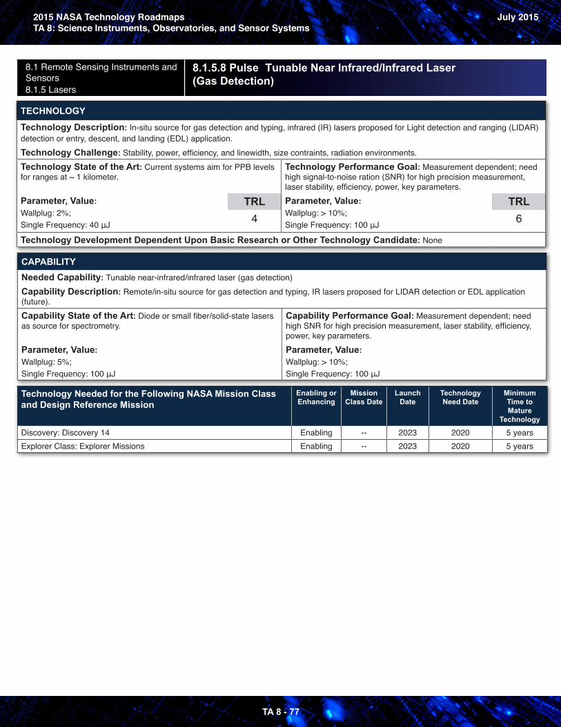
2015 NASA Technology RoadmapsTA 8: Science Instruments, Observatories, and Sensor Systems
July 2015
TA 8 - 77
8.1 Remote Sensing Instruments and Sensors 8.1.5 Lasers
8.1.5.8 Pulse Tunable Near Infrared/Infrared Laser (Gas Detection)
TECHNOLOGY
Technology Description: In-situ source for gas detection and typing, infrared (IR) lasers proposed for Light detection and ranging (LIDAR) detection or entry, descent, and landing (EDL) application.Technology Challenge: Stability, power, efficiency, and linewidth, size contraints, radiation environments.Technology State of the Art: Current systems aim for PPB levels for ranges at ~ 1 kilometer.
Parameter, Value: Wallplug: 2%;Single Frequency: 40 μJ
TRL4
Technology Performance Goal: Measurement dependent; need high signal-to-noise ration (SNR) for high precision measurement, laser stability, efficiency, power, key parameters.Parameter, Value: Wallplug: > 10%; Single Frequency: 100 μJ
TRL6
Technology Development Dependent Upon Basic Research or Other Technology Candidate: None
CAPABILITYNeeded Capability: Tunable near-infrared/infrared laser (gas detection)Capability Description: Remote/in-situ source for gas detection and typing, IR lasers proposed for LIDAR detection or EDL application (future).Capability State of the Art: Diode or small fiber/solid-state lasers as source for spectrometry.
Parameter, Value: Wallplug: 5%;Single Frequency: 100 μJ
Capability Performance Goal: Measurement dependent; need high SNR for high precision measurement, laser stability, efficiency, power, key parameters.Parameter, Value: Wallplug: > 10%;Single Frequency: 100 μJ
Technology Needed for the Following NASA Mission Class and Design Reference Mission
Enabling or Enhancing
Mission Class Date
Launch Date
Technology Need Date
Minimum Time to Mature
Technology
Discovery: Discovery 14 Enabling -- 2023 2020 5 yearsExplorer Class: Explorer Missions Enabling -- 2023 2020 5 years
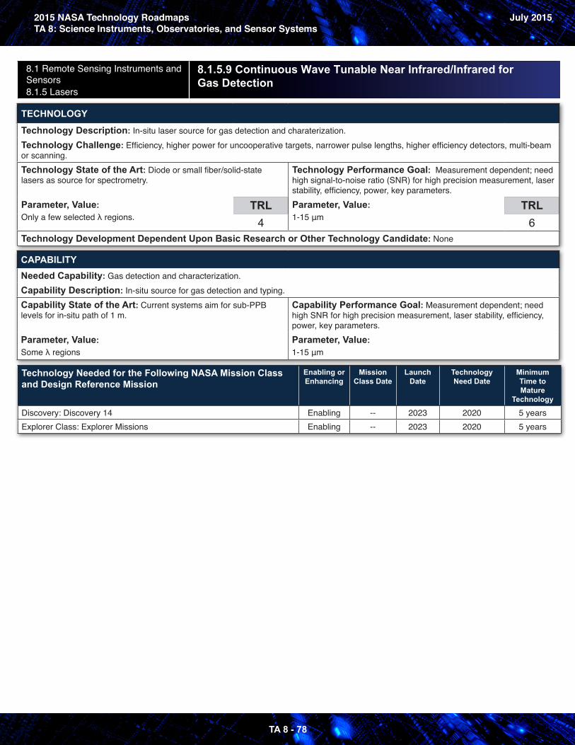
2015 NASA Technology RoadmapsTA 8: Science Instruments, Observatories, and Sensor Systems
July 2015
TA 8 - 78
8.1 Remote Sensing Instruments and Sensors 8.1.5 Lasers
8.1.5.9 Continuous Wave Tunable Near Infrared/Infrared for Gas Detection
TECHNOLOGY
Technology Description: In-situ laser source for gas detection and charaterization.Technology Challenge: Efficiency, higher power for uncooperative targets, narrower pulse lengths, higher efficiency detectors, multi-beam or scanning.Technology State of the Art: Diode or small fiber/solid-state lasers as source for spectrometry.
Parameter, Value: Only a few selected λ regions.
TRL4
Technology Performance Goal: Measurement dependent; need high signal-to-noise ratio (SNR) for high precision measurement, laser stability, efficiency, power, key parameters.Parameter, Value: 1-15 μm
TRL6
Technology Development Dependent Upon Basic Research or Other Technology Candidate: None
CAPABILITYNeeded Capability: Gas detection and characterization.Capability Description: In-situ source for gas detection and typing.Capability State of the Art: Current systems aim for sub-PPB levels for in-situ path of 1 m.
Parameter, Value: Some λ regions
Capability Performance Goal: Measurement dependent; need high SNR for high precision measurement, laser stability, efficiency, power, key parameters.Parameter, Value: 1-15 μm
Technology Needed for the Following NASA Mission Class and Design Reference Mission
Enabling or Enhancing
Mission Class Date
Launch Date
Technology Need Date
Minimum Time to Mature
Technology
Discovery: Discovery 14 Enabling -- 2023 2020 5 yearsExplorer Class: Explorer Missions Enabling -- 2023 2020 5 years
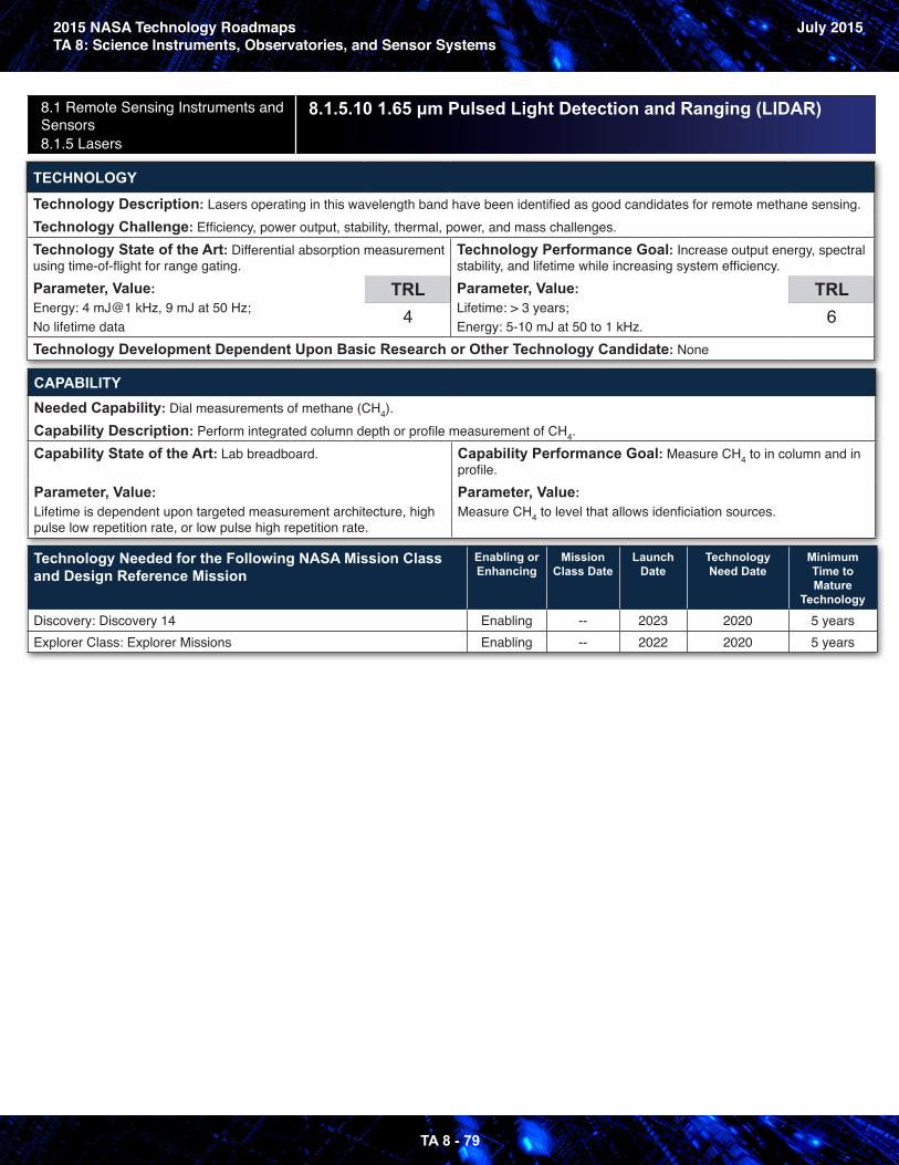
2015 NASA Technology RoadmapsTA 8: Science Instruments, Observatories, and Sensor Systems
July 2015
TA 8 - 79
8.1 Remote Sensing Instruments and Sensors 8.1.5 Lasers
8.1.5.10 1.65 μm Pulsed Light Detection and Ranging (LIDAR)
TECHNOLOGY
Technology Description: Lasers operating in this wavelength band have been identified as good candidates for remote methane sensing.Technology Challenge: Efficiency, power output, stability, thermal, power, and mass challenges.Technology State of the Art: Differential absorption measurement using time-of-flight for range gating.Parameter, Value: Energy: 4 mJ@1 kHz, 9 mJ at 50 Hz;No lifetime data
TRL4
Technology Performance Goal: Increase output energy, spectral stability, and lifetime while increasing system efficiency.Parameter, Value: Lifetime: > 3 years;Energy: 5-10 mJ at 50 to 1 kHz.
TRL6
Technology Development Dependent Upon Basic Research or Other Technology Candidate: None
CAPABILITYNeeded Capability: Dial measurements of methane (CH4).Capability Description: Perform integrated column depth or profile measurement of CH4.Capability State of the Art: Lab breadboard.
Parameter, Value: Lifetime is dependent upon targeted measurement architecture, high pulse low repetition rate, or low pulse high repetition rate.
Capability Performance Goal: Measure CH4 to in column and in profile.Parameter, Value: Measure CH4 to level that allows idenficiation sources.
Technology Needed for the Following NASA Mission Class and Design Reference Mission
Enabling or Enhancing
Mission Class Date
Launch Date
Technology Need Date
Minimum Time to Mature
Technology
Discovery: Discovery 14 Enabling -- 2023 2020 5 yearsExplorer Class: Explorer Missions Enabling -- 2022 2020 5 years
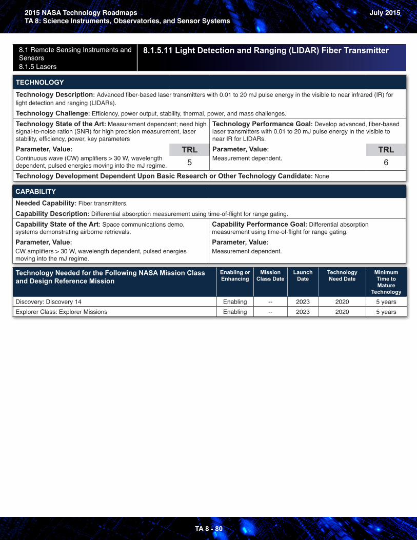
2015 NASA Technology RoadmapsTA 8: Science Instruments, Observatories, and Sensor Systems
July 2015
TA 8 - 80
8.1 Remote Sensing Instruments and Sensors 8.1.5 Lasers
8.1.5.11 Light Detection and Ranging (LIDAR) Fiber Transmitter
TECHNOLOGY
Technology Description: Advanced fiber-based laser transmitters with 0.01 to 20 mJ pulse energy in the visible to near infrared (IR) for light detection and ranging (LIDARs).Technology Challenge: Efficiency, power output, stability, thermal, power, and mass challenges.Technology State of the Art: Measurement dependent; need high signal-to-noise ration (SNR) for high precision measurement, laser stability, efficiency, power, key parametersParameter, Value: Continuous wave (CW) amplifiers > 30 W, wavelength dependent, pulsed energies moving into the mJ regime.
TRL5
Technology Performance Goal: Develop advanced, fiber-based laser transmitters with 0.01 to 20 mJ pulse energy in the visible to near IR for LIDARs. Parameter, Value: Measurement dependent.
TRL6
Technology Development Dependent Upon Basic Research or Other Technology Candidate: None
CAPABILITYNeeded Capability: Fiber transmitters.Capability Description: Differential absorption measurement using time-of-flight for range gating.Capability State of the Art: Space communications demo, systems demonstrating airborne retrievals.Parameter, Value: CW amplifiers > 30 W, wavelength dependent, pulsed energies moving into the mJ regime.
Capability Performance Goal: Differential absorption measurement using time-of-flight for range gating.Parameter, Value: Measurement dependent.
Technology Needed for the Following NASA Mission Class and Design Reference Mission
Enabling or Enhancing
Mission Class Date
Launch Date
Technology Need Date
Minimum Time to Mature
Technology
Discovery: Discovery 14 Enabling -- 2023 2020 5 yearsExplorer Class: Explorer Missions Enabling -- 2023 2020 5 years
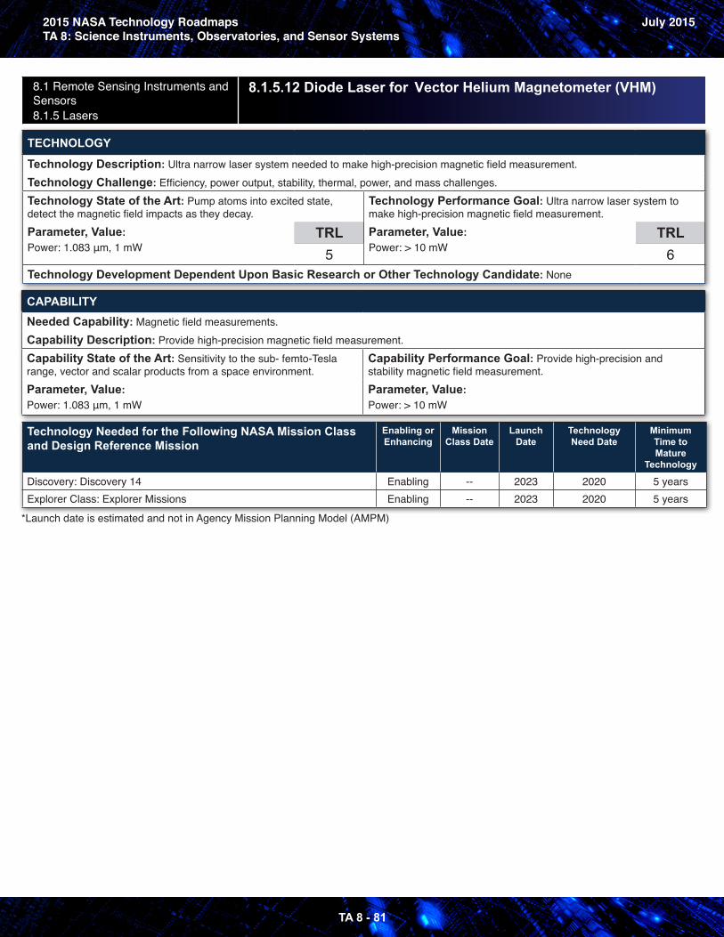
2015 NASA Technology RoadmapsTA 8: Science Instruments, Observatories, and Sensor Systems
July 2015
TA 8 - 81
8.1 Remote Sensing Instruments and Sensors 8.1.5 Lasers
8.1.5.12 Diode Laser for Vector Helium Magnetometer (VHM)
TECHNOLOGY
Technology Description: Ultra narrow laser system needed to make high-precision magnetic field measurement.Technology Challenge: Efficiency, power output, stability, thermal, power, and mass challenges.Technology State of the Art: Pump atoms into excited state, detect the magnetic field impacts as they decay.Parameter, Value: Power: 1.083 μm, 1 mW
TRL5
Technology Performance Goal: Ultra narrow laser system to make high-precision magnetic field measurement.Parameter, Value: Power: > 10 mW
TRL6
Technology Development Dependent Upon Basic Research or Other Technology Candidate: None
CAPABILITYNeeded Capability: Magnetic field measurements.Capability Description: Provide high-precision magnetic field measurement.Capability State of the Art: Sensitivity to the sub- femto-Tesla range, vector and scalar products from a space environment.Parameter, Value: Power: 1.083 μm, 1 mW
Capability Performance Goal: Provide high-precision and stability magnetic field measurement.Parameter, Value: Power: > 10 mW
Technology Needed for the Following NASA Mission Class and Design Reference Mission
Enabling or Enhancing
Mission Class Date
Launch Date
Technology Need Date
Minimum Time to Mature
Technology
Discovery: Discovery 14 Enabling -- 2023 2020 5 yearsExplorer Class: Explorer Missions Enabling -- 2023 2020 5 years
*Launch date is estimated and not in Agency Mission Planning Model (AMPM)
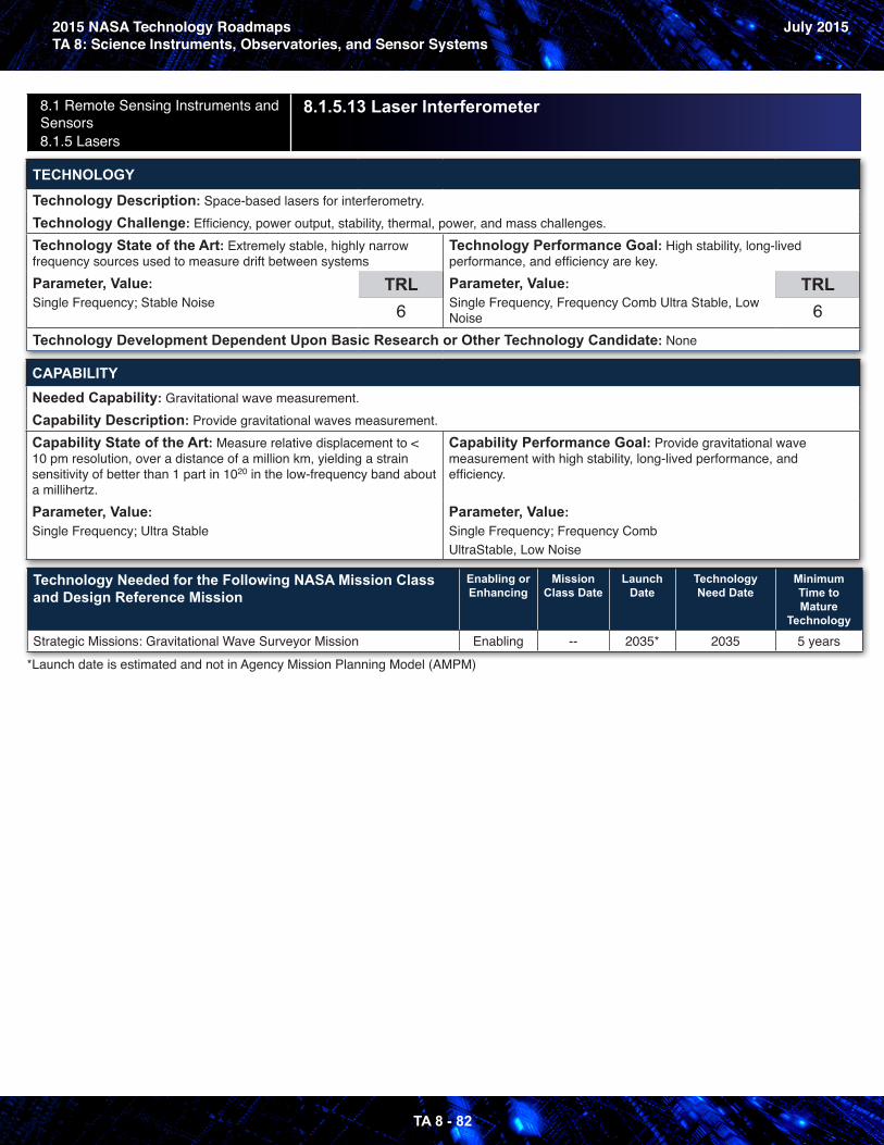
2015 NASA Technology RoadmapsTA 8: Science Instruments, Observatories, and Sensor Systems
July 2015
TA 8 - 82
8.1 Remote Sensing Instruments and Sensors 8.1.5 Lasers
8.1.5.13 Laser Interferometer
TECHNOLOGY
Technology Description: Space-based lasers for interferometry.Technology Challenge: Efficiency, power output, stability, thermal, power, and mass challenges.Technology State of the Art: Extremely stable, highly narrow frequency sources used to measure drift between systemsParameter, Value: Single Frequency; Stable Noise
TRL6
Technology Performance Goal: High stability, long-lived performance, and efficiency are key.Parameter, Value: Single Frequency, Frequency Comb Ultra Stable, Low Noise
TRL6
Technology Development Dependent Upon Basic Research or Other Technology Candidate: None
CAPABILITYNeeded Capability: Gravitational wave measurement.Capability Description: Provide gravitational waves measurement.Capability State of the Art: Measure relative displacement to < 10 pm resolution, over a distance of a million km, yielding a strain sensitivity of better than 1 part in 1020 in the low-frequency band about a millihertz.Parameter, Value: Single Frequency; Ultra Stable
Capability Performance Goal: Provide gravitational wave measurement with high stability, long-lived performance, and efficiency.
Parameter, Value: Single Frequency; Frequency Comb UltraStable, Low Noise
Technology Needed for the Following NASA Mission Class and Design Reference Mission
Enabling or Enhancing
Mission Class Date
Launch Date
Technology Need Date
Minimum Time to Mature
Technology
Strategic Missions: Gravitational Wave Surveyor Mission Enabling -- 2035* 2035 5 years*Launch date is estimated and not in Agency Mission Planning Model (AMPM)
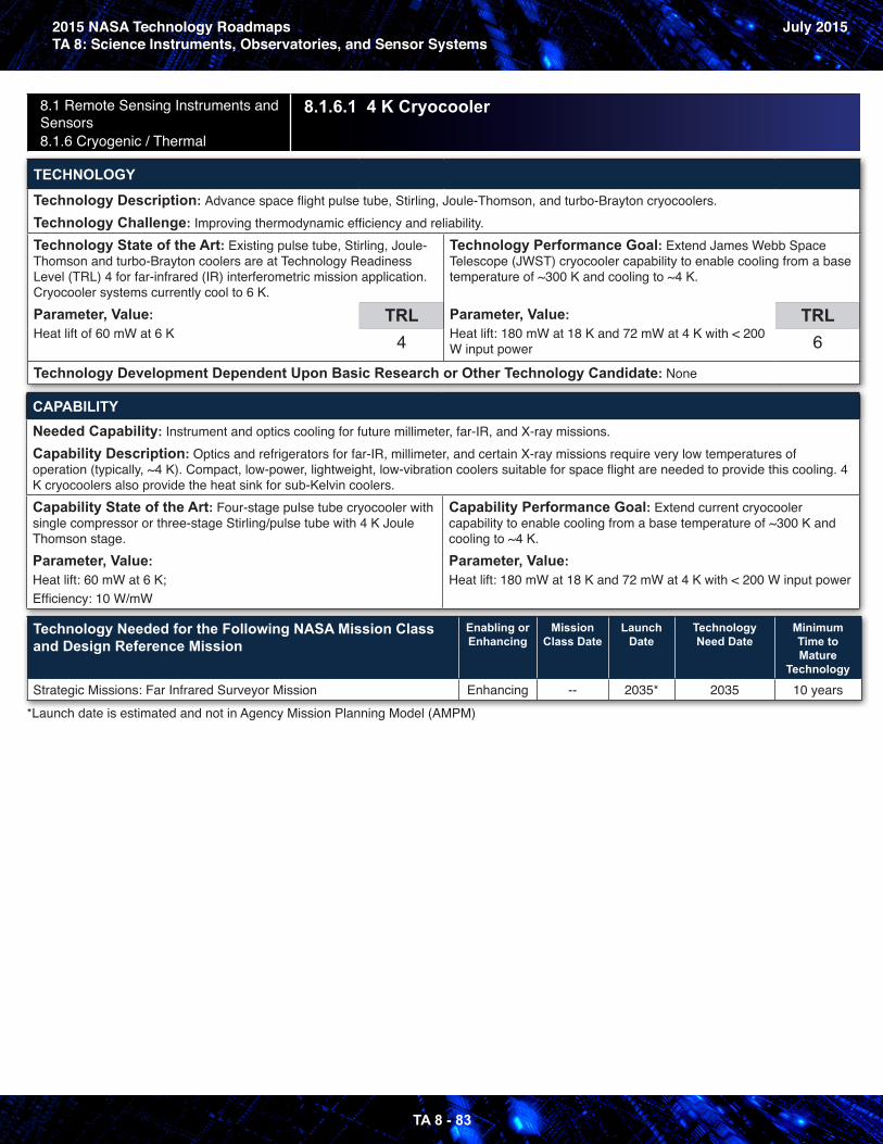
2015 NASA Technology RoadmapsTA 8: Science Instruments, Observatories, and Sensor Systems
July 2015
TA 8 - 83
8.1 Remote Sensing Instruments and Sensors 8.1.6 Cryogenic / Thermal
8.1.6.1 4 K Cryocooler
TECHNOLOGY
Technology Description: Advance space flight pulse tube, Stirling, Joule-Thomson, and turbo-Brayton cryocoolers.Technology Challenge: Improving thermodynamic efficiency and reliability.Technology State of the Art: Existing pulse tube, Stirling, Joule-Thomson and turbo-Brayton coolers are at Technology Readiness Level (TRL) 4 for far-infrared (IR) interferometric mission application. Cryocooler systems currently cool to 6 K.Parameter, Value: Heat lift of 60 mW at 6 K
TRL4
Technology Performance Goal: Extend James Webb Space Telescope (JWST) cryocooler capability to enable cooling from a base temperature of ~300 K and cooling to ~4 K.
Parameter, Value: Heat lift: 180 mW at 18 K and 72 mW at 4 K with < 200 W input power
TRL6
Technology Development Dependent Upon Basic Research or Other Technology Candidate: None
CAPABILITYNeeded Capability: Instrument and optics cooling for future millimeter, far-IR, and X-ray missions.Capability Description: Optics and refrigerators for far-IR, millimeter, and certain X-ray missions require very low temperatures of operation (typically, ~4 K). Compact, low-power, lightweight, low-vibration coolers suitable for space flight are needed to provide this cooling. 4 K cryocoolers also provide the heat sink for sub-Kelvin coolers.Capability State of the Art: Four-stage pulse tube cryocooler with single compressor or three-stage Stirling/pulse tube with 4 K Joule Thomson stage.Parameter, Value: Heat lift: 60 mW at 6 K;Efficiency: 10 W/mW
Capability Performance Goal: Extend current cryocooler capability to enable cooling from a base temperature of ~300 K and cooling to ~4 K.Parameter, Value: Heat lift: 180 mW at 18 K and 72 mW at 4 K with < 200 W input power
Technology Needed for the Following NASA Mission Class and Design Reference Mission
Enabling or Enhancing
Mission Class Date
Launch Date
Technology Need Date
Minimum Time to Mature
Technology
Strategic Missions: Far Infrared Surveyor Mission Enhancing -- 2035* 2035 10 years*Launch date is estimated and not in Agency Mission Planning Model (AMPM)
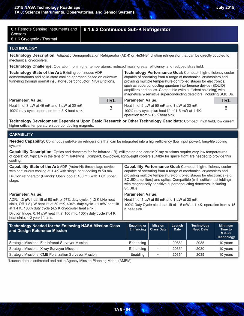
2015 NASA Technology RoadmapsTA 8: Science Instruments, Observatories, and Sensor Systems
July 2015
TA 8 - 84
8.1 Remote Sensing Instruments and Sensors 8.1.6 Cryogenic / Thermal
8.1.6.2 Continuous Sub-K Refrigerator
TECHNOLOGY
Technology Description: Adiabatic Demagnetization Refrigerator (ADR) or He3/He4 dilution refrigerator that can be directly coupled to mechanical cryocoolers.Technology Challenge: Operation from higher temperatures, reduced mass, greater efficiency, and reduced stray field.Technology State of the Art: Existing continuous ADR demonstrations and solid-state cooling approach based on quantum tunneling through normal insulator-superconductor (NIS) junctions.
Parameter, Value: Heat lift of 3 μW at 46 mK and 1 μW at 30 mK;100% duty cycle: operation from 5 K heat sink.
TRL3
Technology Performance Goal: Compact, high-efficiency cooler capable of operating from a range of mechanical cryocoolers and providing multiple temperature-controlled stages for electronics, such as superconducting quantum interference device (SQUID) amplifiers,and optics. Compatible (with sufficient shielding) with magnetically-sensitive superconducting detectors, including SQUIDs.Parameter, Value: Heat lift of 5 μW at 50 mK and 1 μW at 30 mK;100% duty cycle plus heat lift of 1-5 mW at 1-4K: operation from > 15 K heat sink
TRL6
Technology Development Dependent Upon Basic Research or Other Technology Candidate: Compact, high field, low current, higher critical temperature superconducting magnets.
CAPABILITYNeeded Capability: Continuous sub-Kelvin refrigerators that can be integrated into a high-efficiency (low input power), long-life cooling system.Capability Description: Optics and detectors for far-infrared (IR), millimeter, and certain X-ray missions require very low temperatures of operation, typically in the tens of milli-Kelvins. Compact, low-power, lightweight coolers suitable for space flight are needed to provide this cooling.Capability State of the Art: ADR (Astro-H): three-stage device with continuous cooling at 1.4K with single-shot cooling to 50 mK.Dilution refrigerator (Planck): Open loop at 100 mK with 1.6K upper stage.
Parameter, Value: ADR: 1.3 μW heat lift at 50 mK, > 97% duty cycle, (1.2 K LHe heat sink), OR 1.3 μW heat lift at 50 mK, >94% duty cycle + 1 mW heat lift at 1.4 K, 100% duty cycle (4.5 K cryocooler heat sink).Dilution fridge: 0.14 μW heat lift at 100 mK, 100% duty cycle (1.4 K heat sink), ~ 2 year lifetime.
Capability Performance Goal: Compact, high-efficiency cooler capable of operating from a range of mechanical cryocoolers and providing multiple temperature-controlled stages for electronics (e.g., SQUID amplifiers) and optics. Compatible (with sufficient shielding) with magnetically sensitive superconducting detectors, including SQUIDsParameter, Value: Heat lift of 5 μW at 50 mK and 1 μW at 30 mK100% Duty Cycle plus heat lift of 1-5 mW at 1-4K; operation from > 15 K heat sink.
Technology Needed for the Following NASA Mission Class and Design Reference Mission
Enabling or Enhancing
Mission Class Date
Launch Date
Technology Need Date
Minimum Time to Mature
Technology
Strategic Missions: Far Infrared Surveyor Mission Enhancing -- 2035* 2035 10 yearsStrategic Missions: X-ray Surveyor Mission Enhancing -- 2035* 2030 10 yearsStrategic Missions: CMB Polarization Surveyor Mission Enabling -- 2035* 2035 10 years
*Launch date is estimated and not in Agency Mission Planning Model (AMPM)
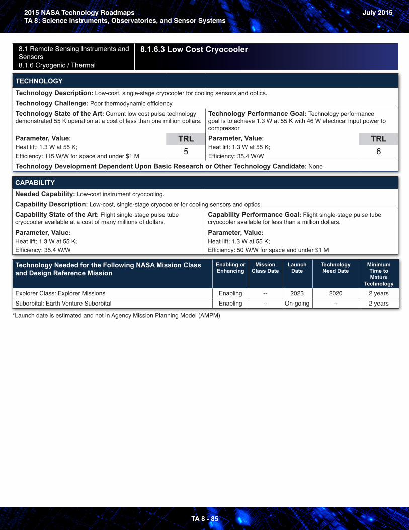
2015 NASA Technology RoadmapsTA 8: Science Instruments, Observatories, and Sensor Systems
July 2015
TA 8 - 85
8.1 Remote Sensing Instruments and Sensors 8.1.6 Cryogenic / Thermal
8.1.6.3 Low Cost Cryocooler
TECHNOLOGY
Technology Description: Low-cost, single-stage cryocooler for cooling sensors and optics.Technology Challenge: Poor thermodynamic efficiency.Technology State of the Art: Current low cost pulse technology demonstrated 55 K operation at a cost of less than one million dollars.
Parameter, Value: Heat lift: 1.3 W at 55 K;Efficiency: 115 W/W for space and under $1 M
TRL5
Technology Performance Goal: Technology performance goal is to achieve 1.3 W at 55 K with 46 W electrical input power to compressor.Parameter, Value: Heat lift: 1.3 W at 55 K; Efficiency: 35.4 W/W
TRL6
Technology Development Dependent Upon Basic Research or Other Technology Candidate: None
CAPABILITYNeeded Capability: Low-cost instrument cryocooling.Capability Description: Low-cost, single-stage cryocooler for cooling sensors and optics.Capability State of the Art: Flight single-stage pulse tube cryocooler available at a cost of many millions of dollars.Parameter, Value: Heat lift; 1.3 W at 55 K;Efficiency: 35.4 W/W
Capability Performance Goal: Flight single-stage pulse tube cryocooler available for less than a million dollars.Parameter, Value: Heat lift: 1.3 W at 55 K;Efficiency: 50 W/W for space and under $1 M
Technology Needed for the Following NASA Mission Class and Design Reference Mission
Enabling or Enhancing
Mission Class Date
Launch Date
Technology Need Date
Minimum Time to Mature
Technology
Explorer Class: Explorer Missions Enabling -- 2023 2020 2 yearsSuborbital: Earth Venture Suborbital Enabling -- On-going -- 2 years
*Launch date is estimated and not in Agency Mission Planning Model (AMPM)
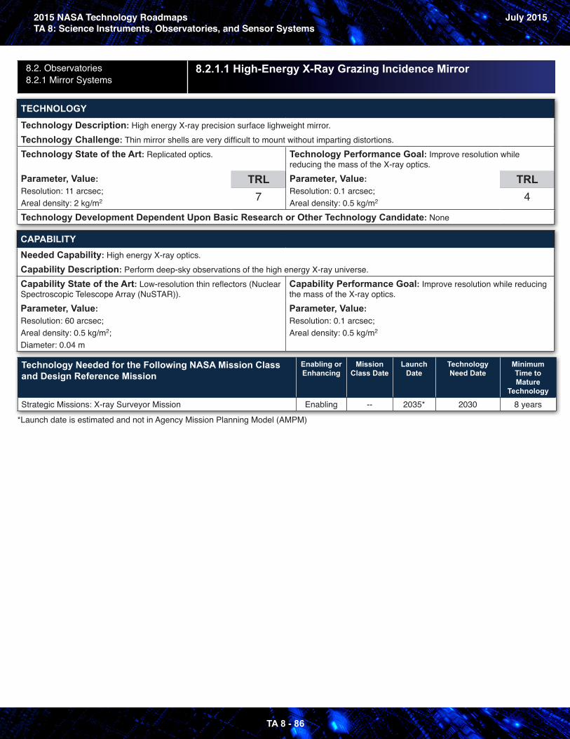
2015 NASA Technology RoadmapsTA 8: Science Instruments, Observatories, and Sensor Systems
July 2015
TA 8 - 86
8.2. Observatories8.2.1 Mirror Systems
8.2.1.1 High-Energy X-Ray Grazing Incidence Mirror
TECHNOLOGY
Technology Description: High energy X-ray precision surface lighweight mirror.Technology Challenge: Thin mirror shells are very difficult to mount without imparting distortions.Technology State of the Art: Replicated optics.
Parameter, Value: Resolution: 11 arcsec;Areal density: 2 kg/m2
TRL7
Technology Performance Goal: Improve resolution while reducing the mass of the X-ray optics.Parameter, Value: Resolution: 0.1 arcsec;Areal density: 0.5 kg/m2
TRL4
Technology Development Dependent Upon Basic Research or Other Technology Candidate: None
CAPABILITYNeeded Capability: High energy X-ray optics.Capability Description: Perform deep-sky observations of the high energy X-ray universe.Capability State of the Art: Low-resolution thin reflectors (Nuclear Spectroscopic Telescope Array (NuSTAR)).Parameter, Value: Resolution: 60 arcsec;Areal density: 0.5 kg/m2;Diameter: 0.04 m
Capability Performance Goal: Improve resolution while reducing the mass of the X-ray optics.Parameter, Value: Resolution: 0.1 arcsec;Areal density: 0.5 kg/m2
Technology Needed for the Following NASA Mission Class and Design Reference Mission
Enabling or Enhancing
Mission Class Date
Launch Date
Technology Need Date
Minimum Time to Mature
Technology
Strategic Missions: X-ray Surveyor Mission Enabling -- 2035* 2030 8 years
*Launch date is estimated and not in Agency Mission Planning Model (AMPM)
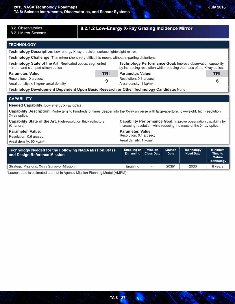
2015 NASA Technology RoadmapsTA 8: Science Instruments, Observatories, and Sensor Systems
July 2015
TA 8 - 87
8.2. Observatories8.2.1 Mirror Systems
8.2.1.2 Low-Energy X-Ray Grazing Incidence Mirror
TECHNOLOGY
Technology Description: Low-energy X-ray precision surface lightweight mirror.Technology Challenge: Thin mirror shells very difficult to mount without imparting distortions.Technology State of the Art: Replicated optics, segmented mirrors, and slumped silicon optics.Parameter, Value: Resolution: 10 arcsec; Areal density: < 1 kg/m2 areal density
TRL9
Technology Performance Goal: Improve observation capability by increasing resolution while reducing the mass of the X-ray optics.Parameter, Value: Resolution: 0.1 arcsec;Areal density: 1 kg/m2
TRL6
Technology Development Dependent Upon Basic Research or Other Technology Candidate: None
CAPABILITYNeeded Capability: Low energy X-ray optics.Capability Description: Probe tens to hundreds of times deeper into the X-ray universe with large-aperture, low-weight, high-resolution X-ray optics.Capability State of the Art: High-resolution thick reflectors (Chandra).Parameter, Value: Resolution: 0.6 arcsec;Areal density: 60 kg/m2
Capability Performance Goal: Improve observation capability by increasing resolution while reducing the mass of the X-ray optics.Parameter, Value: Resolution: 0.1 arcsec;Areal density: 1 kg/m2
Technology Needed for the Following NASA Mission Class and Design Reference Mission
Enabling or Enhancing
Mission Class Date
Launch Date
Technology Need Date
Minimum Time to Mature
Technology
Strategic Missions: X-ray Surveyor Mission Enabling -- 2035* 2030 8 years
*Launch date is estimated and not in Agency Mission Planning Model (AMPM)
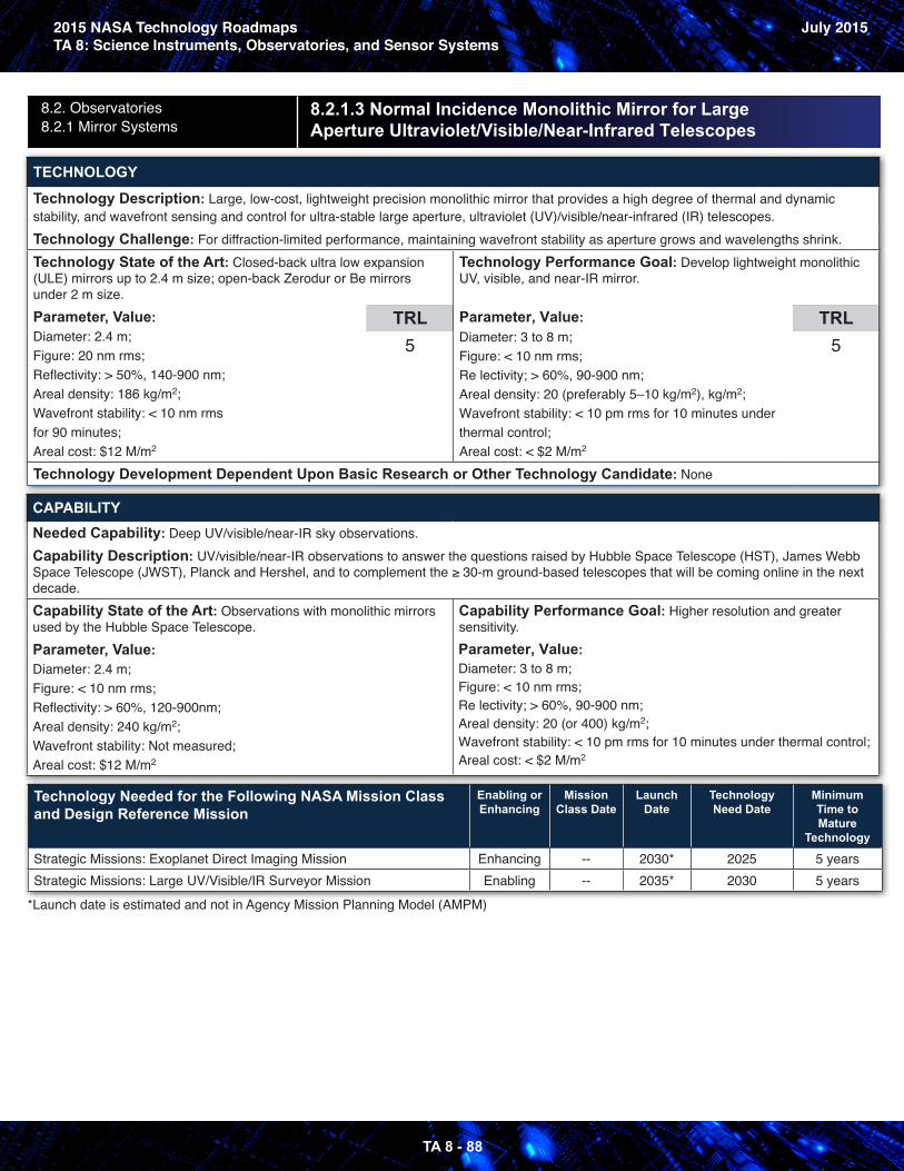
2015 NASA Technology RoadmapsTA 8: Science Instruments, Observatories, and Sensor Systems
July 2015
TA 8 - 88
8.2. Observatories8.2.1 Mirror Systems
8.2.1.3 Normal Incidence Monolithic Mirror for Large Aperture Ultraviolet/Visible/Near-Infrared Telescopes
TECHNOLOGY
Technology Description: Large, low-cost, lightweight precision monolithic mirror that provides a high degree of thermal and dynamic stability, and wavefront sensing and control for ultra-stable large aperture, ultraviolet (UV)/visible/near-infrared (IR) telescopes.Technology Challenge: For diffraction-limited performance, maintaining wavefront stability as aperture grows and wavelengths shrink.Technology State of the Art: Closed-back ultra low expansion (ULE) mirrors up to 2.4 m size; open-back Zerodur or Be mirrors under 2 m size. Parameter, Value: Diameter: 2.4 m; Figure: 20 nm rms; Reflectivity: > 50%, 140-900 nm; Areal density: 186 kg/m2;Wavefront stability: < 10 nm rmsfor 90 minutes; Areal cost: $12 M/m2
TRL5
Technology Performance Goal: Develop lightweight monolithic UV, visible, and near-IR mirror.
Parameter, Value: Diameter: 3 to 8 m; Figure: < 10 nm rms; Re lectivity; > 60%, 90-900 nm; Areal density: 20 (preferably 5–10 kg/m2), kg/m2; Wavefront stability: < 10 pm rms for 10 minutes under thermal control; Areal cost: < $2 M/m2
TRL5
Technology Development Dependent Upon Basic Research or Other Technology Candidate: None
CAPABILITYNeeded Capability: Deep UV/visible/near-IR sky observations.Capability Description: UV/visible/near-IR observations to answer the questions raised by Hubble Space Telescope (HST), James Webb Space Telescope (JWST), Planck and Hershel, and to complement the ≥ 30-m ground-based telescopes that will be coming online in the next decade.Capability State of the Art: Observations with monolithic mirrors used by the Hubble Space Telescope.Parameter, Value: Diameter: 2.4 m;Figure: < 10 nm rms;Reflectivity: > 60%, 120-900nm; Areal density: 240 kg/m2;Wavefront stability: Not measured;Areal cost: $12 M/m2
Capability Performance Goal: Higher resolution and greater sensitivity.Parameter, Value: Diameter: 3 to 8 m; Figure: < 10 nm rms; Re lectivity; > 60%, 90-900 nm; Areal density: 20 (or 400) kg/m2;Wavefront stability: < 10 pm rms for 10 minutes under thermal control; Areal cost: < $2 M/m2
Technology Needed for the Following NASA Mission Class and Design Reference Mission
Enabling or Enhancing
Mission Class Date
Launch Date
Technology Need Date
Minimum Time to Mature
Technology
Strategic Missions: Exoplanet Direct Imaging Mission Enhancing -- 2030* 2025 5 yearsStrategic Missions: Large UV/Visible/IR Surveyor Mission Enabling -- 2035* 2030 5 years
*Launch date is estimated and not in Agency Mission Planning Model (AMPM)
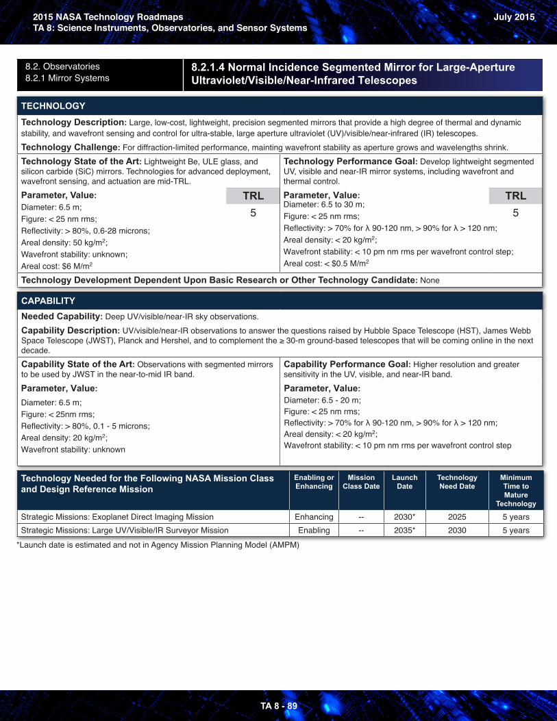
2015 NASA Technology RoadmapsTA 8: Science Instruments, Observatories, and Sensor Systems
July 2015
TA 8 - 89
8.2. Observatories8.2.1 Mirror Systems
8.2.1.4 Normal Incidence Segmented Mirror for Large-Aperture Ultraviolet/Visible/Near-Infrared Telescopes
TECHNOLOGY
Technology Description: Large, low-cost, lightweight, precision segmented mirrors that provide a high degree of thermal and dynamic stability, and wavefront sensing and control for ultra-stable, large aperture ultraviolet (UV)/visible/near-infrared (IR) telescopes.Technology Challenge: For diffraction-limited performance, mainting wavefront stability as aperture grows and wavelengths shrink.Technology State of the Art: Lightweight Be, ULE glass, and silicon carbide (SiC) mirrors. Technologies for advanced deployment, wavefront sensing, and actuation are mid-TRL.Parameter, Value: Diameter: 6.5 m; Figure: < 25 nm rms;Reflectivity: > 80%, 0.6-28 microns;Areal density: 50 kg/m2;Wavefront stability: unknown;Areal cost: $6 M/m2
TRL5
Technology Performance Goal: Develop lightweight segmented UV, visible and near-IR mirror systems, including wavefront and thermal control.Parameter, Value: Diameter: 6.5 to 30 m;Figure: < 25 nm rms;Reflectivity: > 70% for λ 90-120 nm, > 90% for λ > 120 nm;Areal density: < 20 kg/m2;Wavefront stability: < 10 pm nm rms per wavefront control step;Areal cost: < $0.5 M/m2
TRL5
Technology Development Dependent Upon Basic Research or Other Technology Candidate: None
CAPABILITYNeeded Capability: Deep UV/visible/near-IR sky observations.Capability Description: UV/visible/near-IR observations to answer the questions raised by Hubble Space Telescope (HST), James Webb Space Telescope (JWST), Planck and Hershel, and to complement the ≥ 30-m ground-based telescopes that will be coming online in the next decade.Capability State of the Art: Observations with segmented mirrors to be used by JWST in the near-to-mid IR band.Parameter, Value: Diameter: 6.5 m; Figure: < 25nm rms; Reflectivity: > 80%, 0.1 - 5 microns; Areal density: 20 kg/m2; Wavefront stability: unknown
Capability Performance Goal: Higher resolution and greater sensitivity in the UV, visible, and near-IR band.Parameter, Value: Diameter: 6.5 - 20 m;Figure: < 25 nm rms;Reflectivity: > 70% for λ 90-120 nm, > 90% for λ > 120 nm;Areal density: < 20 kg/m2;Wavefront stability: < 10 pm nm rms per wavefront control step
Technology Needed for the Following NASA Mission Class and Design Reference Mission
Enabling or Enhancing
Mission Class Date
Launch Date
Technology Need Date
Minimum Time to Mature
Technology
Strategic Missions: Exoplanet Direct Imaging Mission Enhancing -- 2030* 2025 5 yearsStrategic Missions: Large UV/Visible/IR Surveyor Mission Enabling -- 2035* 2030 5 years
*Launch date is estimated and not in Agency Mission Planning Model (AMPM)
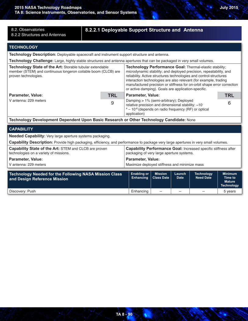
2015 NASA Technology RoadmapsTA 8: Science Instruments, Observatories, and Sensor Systems
July 2015
TA 8 - 90
8.2. Observatories8.2.2 Structures and Antennas
8.2.2.1 Deployable Support Structure and Antenna
TECHNOLOGY
Technology Description: Deployable spacecraft and instrument support structure and antenna.Technology Challenge: Large, highly stable structures and antenna apertures that can be packaged in very small volumes.Technology State of the Art: Storable tubular extendable member (STEM) and continuous longeron coilable boom (CLCB) are proven technologies.
Parameter, Value: V antenna: 229 meters
TRL9
Technology Performance Goal: Thermal-elastic stability; microdynamic stability; and deployed precision, repeatability, and reliability. Active structures technologies and control-structures interaction technologies are also relevant (for example, trading manufactured precision or stiffness for on-orbit shape error correction or active damping). Goals are application-specific.Parameter, Value: Damping > 1% (semi-arbitrary); Deployed relative precision and dimensional stability: ~10-
4 – 10-6 (depends on radio frequency (RF) or optical application)
TRL6
Technology Development Dependent Upon Basic Research or Other Technology Candidate: None
CAPABILITYNeeded Capability: Very large aperture systems packaging.Capability Description: Provide high packaging, efficiency, and performance to package very large apertures in very small volumes.Capability State of the Art: STEM and CLCB are proven technologies on a variety of missions.Parameter, Value: V antenna: 229 meters
Capability Performance Goal: Increased specific stiffness after packaging of very large aperture systems.Parameter, Value: Maximize deployed stiffness and minimize mass
Technology Needed for the Following NASA Mission Class and Design Reference Mission
Enabling or Enhancing
Mission Class Date
Launch Date
Technology Need Date
Minimum Time to Mature
Technology
Discovery: Push Enhancing -- -- -- 5 years
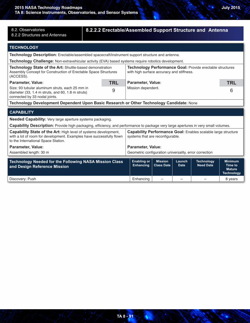
2015 NASA Technology RoadmapsTA 8: Science Instruments, Observatories, and Sensor Systems
July 2015
TA 8 - 91
8.2. Observatories8.2.2 Structures and Antennas
8.2.2.2 Erectable/Assembled Support Structure and Antenna
TECHNOLOGY
Technology Description: Erectable/assembled spacecraft/instrument support structure and antenna.Technology Challenge: Non-extravehicular activity (EVA) based systems require robotics development.Technology State of the Art: Shuttle-based demonstration Assembly Concept for Construction of Erectable Space Structures (ACCESS).Parameter, Value: Size: 93 tubular aluminum struts, each 25 mm in diameter (33, 1.4 m struts, and 60, 1.8 m struts) connected by 33 nodal joints.
TRL9
Technology Performance Goal: Provide erectable structures with high surface accuracy and stiffness.
Parameter, Value: Mission dependent.
TRL6
Technology Development Dependent Upon Basic Research or Other Technology Candidate: None
CAPABILITYNeeded Capability: Very large aperture systems packaging.Capability Description: Provide high packaging, efficiency, and performance to package very large apertures in very small volumes.Capability State of the Art: High level of systems development, with a lot of room for development. Examples have successfully flown to the International Space Station.Parameter, Value: Assembled length: 30 m
Capability Performance Goal: Enables scalable large structure systems that are reconfigurable.
Parameter, Value: Geometric configuration universality, error correction
Technology Needed for the Following NASA Mission Class and Design Reference Mission
Enabling or Enhancing
Mission Class Date
Launch Date
Technology Need Date
Minimum Time to Mature
Technology
Discovery: Push Enhancing -- -- -- 8 years
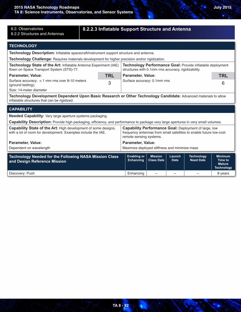
2015 NASA Technology RoadmapsTA 8: Science Instruments, Observatories, and Sensor Systems
July 2015
TA 8 - 92
8.2. Observatories8.2.2 Structures and Antennas
8.2.2.3 Inflatable Support Structure and Antenna
TECHNOLOGY
Technology Description: Inflatable spacecraft/instrument support structure and antenna.Technology Challenge: Requires materials development for higher precision and/or rigidization.Technology State of the Art: Inflatable Antenna Experiment (IAE) flown on Space Transport System (STS)-77.Parameter, Value: Surface accuracy: < 1 mm rms over 8-10 meters (ground testing);Size: 14-meter diameter
TRL3
Technology Performance Goal: Provide inflatable deployment structures with 0.1mm rms accuracy, rigidizability.Parameter, Value: Surface accuracy: 0.1mm rms
TRL6
Technology Development Dependent Upon Basic Research or Other Technology Candidate: Advanced materials to allow inflatable structures that can be rigidized.
CAPABILITYNeeded Capability: Very large aperture systems packaging.Capability Description: Provide high packaging, efficiency, and performance to package very large apertures in very small volumes.Capability State of the Art: High development of some designs, with a lot of room for development. Examples include the IAE.
Parameter, Value: Dependent on wavelength
Capability Performance Goal: Deployment of large, low frequency antennas from small satellites to enable future low-cost remote sensing systems.Parameter, Value: Maximize deployed stiffness and minimize mass
Technology Needed for the Following NASA Mission Class and Design Reference Mission
Enabling or Enhancing
Mission Class Date
Launch Date
Technology Need Date
Minimum Time to Mature
Technology
Discovery: Push Enhancing -- -- -- 8 years
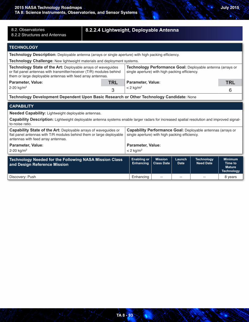
2015 NASA Technology RoadmapsTA 8: Science Instruments, Observatories, and Sensor Systems
July 2015
TA 8 - 93
8.2. Observatories8.2.2 Structures and Antennas
8.2.2.4 Lightweight, Deployable Antenna
TECHNOLOGY
Technology Description: Deployable antenna (arrays or single aperture) with high packing efficiency.Technology Challenge: New lightweight materials and deployment systems.Technology State of the Art: Deployable arrays of waveguides or flat panel antennas with transmitter/receiver (T/R) modules behind them or large deployable antennas with feed array antennas.Parameter, Value: 2-20 kg/m2
TRL3
Technology Performance Goal: Deployable antenna (arrays or single aperture) with high packing efficiency.
Parameter, Value: < 2 kg/m2
TRL6
Technology Development Dependent Upon Basic Research or Other Technology Candidate: None
CAPABILITYNeeded Capability: Lightweight deployable antennas.Capability Description: Lightweight deployable antenna systems enable larger radars for increased spatial resolution and improved signal-to-noise ratio.Capability State of the Art: Deployable arrays of waveguides or flat panel antennas with T/R modules behind them or large deployable antennas with feed array antennas.Parameter, Value: 2-20 kg/m2
Capability Performance Goal: Deployable antennas (arrays or single aperture) with high packing efficiency.
Parameter, Value: < 2 kg/m2
Technology Needed for the Following NASA Mission Class and Design Reference Mission
Enabling or Enhancing
Mission Class Date
Launch Date
Technology Need Date
Minimum Time to Mature
Technology
Discovery: Push Enhancing -- -- -- 8 years
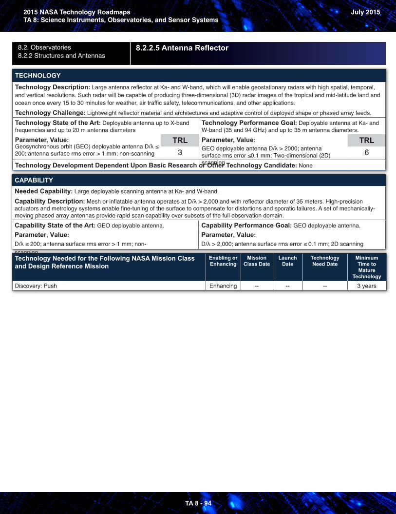
2015 NASA Technology RoadmapsTA 8: Science Instruments, Observatories, and Sensor Systems
July 2015
TA 8 - 94
8.2. Observatories8.2.2 Structures and Antennas
8.2.2.5 Antenna Reflector
TECHNOLOGY
Technology Description: Large antenna reflector at Ka- and W-band, which will enable geostationary radars with high spatial, temporal, and vertical resolutions. Such radar will be capable of producing three-dimensional (3D) radar images of the tropical and mid-latitude land and ocean once every 15 to 30 minutes for weather, air traffic safety, telecommunications, and other applications.Technology Challenge: Lightweight reflector material and architectures and adaptive control of deployed shape or phased array feeds.Technology State of the Art: Deployable antenna up to X-band frequencies and up to 20 m antenna diametersParameter, Value: Geosynchronous orbit (GEO) deployable antenna D/λ ≤ 200; antenna surface rms error > 1 mm; non-scanning
TRL3
Technology Performance Goal: Deployable antenna at Ka- and W-band (35 and 94 GHz) and up to 35 m antenna diameters.Parameter, Value: GEO deployable antenna D/λ > 2000; antenna surface rms error ≤0.1 mm; Two-dimensional (2D) scanning
TRL6
Technology Development Dependent Upon Basic Research or Other Technology Candidate: None
CAPABILITYNeeded Capability: Large deployable scanning antenna at Ka- and W-band.Capability Description: Mesh or inflatable antenna operates at D/λ > 2,000 and with reflector diameter of 35 meters. High-precision actuators and metrology systems enable fine-tuning of the surface to compensate for distortions and sporatic failures. A set of mechanically-moving phased array antennas provide rapid scan capability over subsets of the full observation domain.Capability State of the Art: GEO deployable antenna. Parameter, Value: D/λ ≤ 200; antenna surface rms error > 1 mm; non-scanning
Capability Performance Goal: GEO deployable antenna. Parameter, Value: D/λ > 2,000; antenna surface rms error ≤ 0.1 mm; 2D scanning
Technology Needed for the Following NASA Mission Class and Design Reference Mission
Enabling or Enhancing
Mission Class Date
Launch Date
Technology Need Date
Minimum Time to Mature
Technology
Discovery: Push Enhancing -- -- -- 3 years
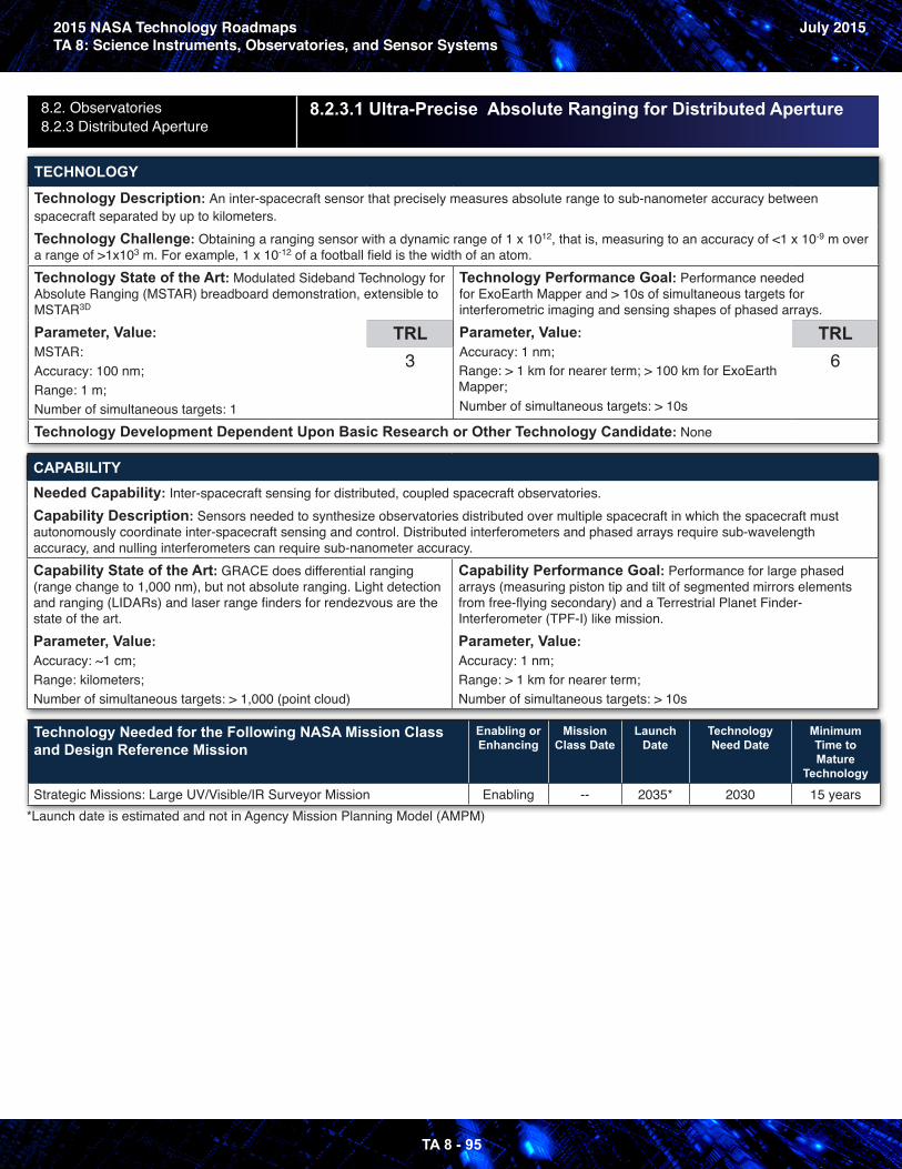
2015 NASA Technology RoadmapsTA 8: Science Instruments, Observatories, and Sensor Systems
July 2015
TA 8 - 95
8.2. Observatories8.2.3 Distributed Aperture
8.2.3.1 Ultra-Precise Absolute Ranging for Distributed Aperture
TECHNOLOGY
Technology Description: An inter-spacecraft sensor that precisely measures absolute range to sub-nanometer accuracy between spacecraft separated by up to kilometers.Technology Challenge: Obtaining a ranging sensor with a dynamic range of 1 x 10¹², that is, measuring to an accuracy of <1 x 10⁻⁹ m over a range of >1x10³ m. For example, 1 x 10-12 of a football field is the width of an atom.Technology State of the Art: Modulated Sideband Technology for Absolute Ranging (MSTAR) breadboard demonstration, extensible to MSTAR3D
Parameter, Value: MSTAR: Accuracy: 100 nm; Range: 1 m; Number of simultaneous targets: 1
TRL3
Technology Performance Goal: Performance needed for ExoEarth Mapper and > 10s of simultaneous targets for interferometric imaging and sensing shapes of phased arrays.Parameter, Value: Accuracy: 1 nm; Range: > 1 km for nearer term; > 100 km for ExoEarth Mapper; Number of simultaneous targets: > 10s
TRL6
Technology Development Dependent Upon Basic Research or Other Technology Candidate: None
CAPABILITYNeeded Capability: Inter-spacecraft sensing for distributed, coupled spacecraft observatories.Capability Description: Sensors needed to synthesize observatories distributed over multiple spacecraft in which the spacecraft must autonomously coordinate inter-spacecraft sensing and control. Distributed interferometers and phased arrays require sub-wavelength accuracy, and nulling interferometers can require sub-nanometer accuracy.Capability State of the Art: GRACE does differential ranging (range change to 1,000 nm), but not absolute ranging. Light detection and ranging (LIDARs) and laser range finders for rendezvous are the state of the art.Parameter, Value: Accuracy: ~1 cm; Range: kilometers;Number of simultaneous targets: > 1,000 (point cloud)
Capability Performance Goal: Performance for large phased arrays (measuring piston tip and tilt of segmented mirrors elements from free-flying secondary) and a Terrestrial Planet Finder-Interferometer (TPF-I) like mission.Parameter, Value: Accuracy: 1 nm; Range: > 1 km for nearer term;Number of simultaneous targets: > 10s
Technology Needed for the Following NASA Mission Class and Design Reference Mission
Enabling or Enhancing
Mission Class Date
Launch Date
Technology Need Date
Minimum Time to Mature
Technology
Strategic Missions: Large UV/Visible/IR Surveyor Mission Enabling -- 2035* 2030 15 years*Launch date is estimated and not in Agency Mission Planning Model (AMPM)
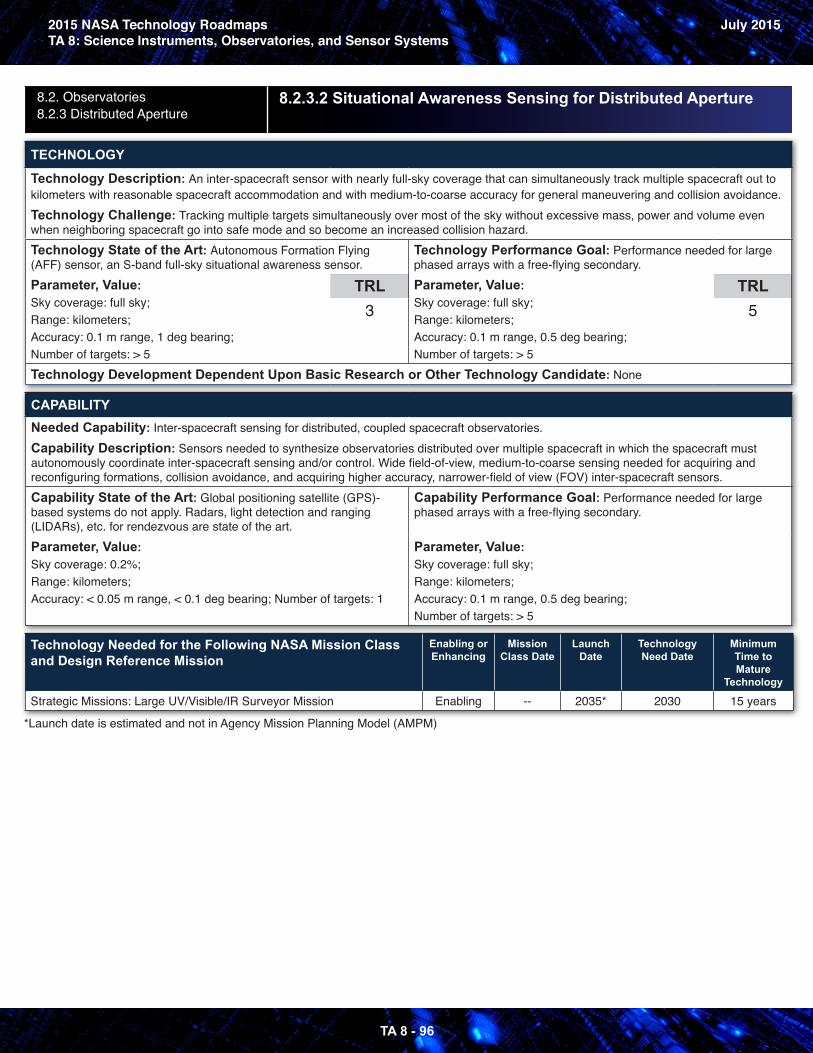
2015 NASA Technology RoadmapsTA 8: Science Instruments, Observatories, and Sensor Systems
July 2015
TA 8 - 96
8.2. Observatories8.2.3 Distributed Aperture
8.2.3.2 Situational Awareness Sensing for Distributed Aperture
TECHNOLOGY
Technology Description: An inter-spacecraft sensor with nearly full-sky coverage that can simultaneously track multiple spacecraft out to kilometers with reasonable spacecraft accommodation and with medium-to-coarse accuracy for general maneuvering and collision avoidance.Technology Challenge: Tracking multiple targets simultaneously over most of the sky without excessive mass, power and volume even when neighboring spacecraft go into safe mode and so become an increased collision hazard.Technology State of the Art: Autonomous Formation Flying (AFF) sensor, an S-band full-sky situational awareness sensor.Parameter, Value: Sky coverage: full sky;Range: kilometers;Accuracy: 0.1 m range, 1 deg bearing;Number of targets: > 5
TRL3
Technology Performance Goal: Performance needed for large phased arrays with a free-flying secondary.Parameter, Value: Sky coverage: full sky;Range: kilometers;Accuracy: 0.1 m range, 0.5 deg bearing;Number of targets: > 5
TRL5
Technology Development Dependent Upon Basic Research or Other Technology Candidate: None
CAPABILITYNeeded Capability: Inter-spacecraft sensing for distributed, coupled spacecraft observatories.Capability Description: Sensors needed to synthesize observatories distributed over multiple spacecraft in which the spacecraft must autonomously coordinate inter-spacecraft sensing and/or control. Wide field-of-view, medium-to-coarse sensing needed for acquiring and reconfiguring formations, collision avoidance, and acquiring higher accuracy, narrower-field of view (FOV) inter-spacecraft sensors.Capability State of the Art: Global positioning satellite (GPS)-based systems do not apply. Radars, light detection and ranging (LIDARs), etc. for rendezvous are state of the art.Parameter, Value: Sky coverage: 0.2%;Range: kilometers;Accuracy: < 0.05 m range, < 0.1 deg bearing; Number of targets: 1
Capability Performance Goal: Performance needed for large phased arrays with a free-flying secondary.
Parameter, Value: Sky coverage: full sky;Range: kilometers;Accuracy: 0.1 m range, 0.5 deg bearing;Number of targets: > 5
Technology Needed for the Following NASA Mission Class and Design Reference Mission
Enabling or Enhancing
Mission Class Date
Launch Date
Technology Need Date
Minimum Time to Mature
Technology
Strategic Missions: Large UV/Visible/IR Surveyor Mission Enabling -- 2035* 2030 15 years
*Launch date is estimated and not in Agency Mission Planning Model (AMPM)
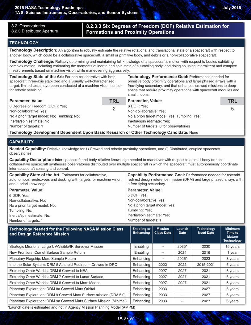
2015 NASA Technology RoadmapsTA 8: Science Instruments, Observatories, and Sensor Systems
July 2015
TA 8 - 97
8.2. Observatories8.2.3 Distributed Aperture
8.2.3.3 Six Degrees of Freedom (DOF) Relative Estimation for Formations and Proximity Operations
TECHNOLOGY
Technology Description: An algorithm to robustly estimate the relative rotational and translational state of a spacecraft with respect to another body, which could be a collaborative spacecraft, a small or primitive body, and debris or a non-collaborative spacecraft.Technology Challenge: Reliably determining and maintaining full knowledge of a spacecraft’s motion with respect to bodies exhibiting complex motion, including estimating the moments of inertia and spin state of a tumbling body, and doing so using intermittent and complex measurements based on machine vision while maneuvering aggressively.Technology State of the Art: For non-collaborative with both spacecraft three-axis stabilized and a visually well-characterized target, limited tests have been conducted of a machine vision sensor for robotic servicing.
Parameter, Value: 6 Degrees of Freedom (DOF): Yes;Non-collaborative: Yes;No a priori target model: No; Tumbling: No;Inertia/spin estimate: No;Number of targets: 1
TRL2
Technology Performance Goal: Performance needed for primitive body proximity operations and large phased arrays with a free-flying secondary, and that enhances crewed missions to deep space that require proximity operations with spacecraft modules and small moons.Parameter, Value: 6 DOF: Yes;Non-collaborative: Yes;No a priori target model: Yes; Tumbling: Yes;Inertia/spin estimate: Yes;Number of targets: 6 for observatories
TRL5
Technology Development Dependent Upon Basic Research or Other Technology Candidate: None
CAPABILITYNeeded Capability: Relative knowledge for 1) Crewed and robotic proximity operations, and 2) Distributed, coupled spacecraft observatories.Capability Description: Inter-spacecraft and body-relative knowledge needed to maneuver with respect to a small body or non-collaborative spacecraft synthesize observatories distributed over multiple spacecraft in which the spacecraft must autonomously coordinate inter-spacecraft sensing and control.Capability State of the Art: Estimators for collaborative, autonomous rendezvous and docking with targets for machine vision and a priori knowledge.Parameter, Value: 6 DOF: Yes;Non-collaborative: No;No a priori target model: No;Tumbling: No;Inertia/spin estimate: No;Number of targets: 1
Capability Performance Goal: Performance needed for asteroid redirect design reference mission (DRM) and large phased arrays with a free-flying secondary.Parameter, Value: 6 DOF: Yes;Non-collaborative: Yes;No a priori target model: Yes;Tumbling: Yes;Inertia/spin estimate: Yes;Number of targets: 1
Technology Needed for the Following NASA Mission Class and Design Reference Mission
Enabling or Enhancing
Mission Class Date
Launch Date
Technology Need Date
Minimum Time to Mature
Technology
Strategic Missions: Large UV/Visible/IR Surveyor Mission Enabling -- 2035* 2030 15 yearsNew Frontiers: Comet Surface Sample Return Enabling -- 2024 2016 1 yearPlanetary Flagship: Mars Sample Return Enhancing -- 2026* 2023 8 yearsInto the Solar System: DRM 5 Asteroid Redirect – Crewed in DRO Enhancing 2022 2022 2015-2021 6 yearsExploring Other Worlds: DRM 6 Crewed to NEA Enhancing 2027 2027 2021 6 yearsExploring Other Worlds: DRM 7 Crewed to Lunar Surface Enhancing 2027 2027 2021 6 yearsExploring Other Worlds: DRM 8 Crewed to Mars Moons Enhancing 2027 2027 2021 6 yearsPlanetary Exploration: DRM 8a Crewed Mars Orbital Enhancing 2033 -- 2027 6 yearsPlanetary Exploration: DRM 9 Crewed Mars Surface mission (DRA 5.0) Enhancing 2033 -- 2027 6 yearsPlanetary Exploration: DRM 9a Crewed Mars Surface Mission (Minimal) Enhancing 2033 -- 2027 6 years
*Launch date is estimated and not in Agency Mission Planning Model (AMPM)
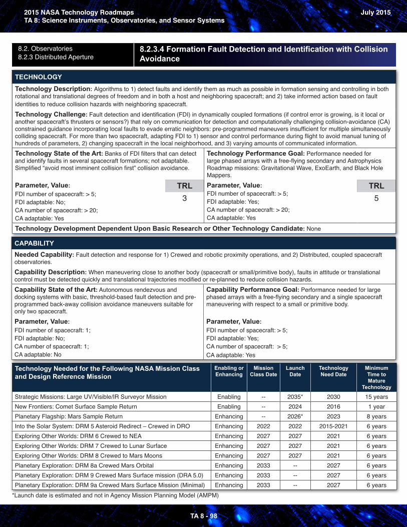
2015 NASA Technology RoadmapsTA 8: Science Instruments, Observatories, and Sensor Systems
July 2015
TA 8 - 98
8.2. Observatories8.2.3 Distributed Aperture
8.2.3.4 Formation Fault Detection and Identification with CollisionAvoidance
TECHNOLOGY
Technology Description: Algorithms to 1) detect faults and identify them as much as possible in formation sensing and controlling in both rotational and translational degrees of freedom and in both a host and neighboring spacecraft; and 2) take informed action based on fault identities to reduce collision hazards with neighboring spacecraft.Technology Challenge: Fault detection and identification (FDI) in dynamically coupled formations (if control error is growing, is it local or another spacecraft’s thrusters or sensors?) that rely on communication for detection and computationally challenging collision-avoidance (CA) constrained guidance incorporating local faults to evade erratic neighbors: pre-programmed maneuvers insufficient for multiple simultaneously colliding spacecraft. For more than two spacecraft, adapting FDI to 1) sensor and control performance during flight to avoid manual tuning of hundreds of parameters, 2) changing spacecraft in the local neighborhood, and 3) varying amounts of communicated information.Technology State of the Art: Banks of FDI filters that can detect and identify faults in several spacecraft formations; not adaptable. Simplified “avoid most imminent collision first” collision avoidance.
Parameter, Value: FDI number of spacecraft: > 5;FDI adaptable: No;CA number of spacecraft: > 20;CA adaptable: Yes
TRL3
Technology Performance Goal: Performance needed for large phased arrays with a free-flying secondary and Astrophysics Roadmap missions: Gravitational Wave, ExoEarth, and Black Hole Mappers.Parameter, Value: FDI number of spacecraft: > 5;FDI adaptable: Yes;CA number of spacecraft: > 20;CA adaptable: Yes
TRL5
Technology Development Dependent Upon Basic Research or Other Technology Candidate: None
CAPABILITYNeeded Capability: Fault detection and response for 1) Crewed and robotic proximity operations, and 2) Distributed, coupled spacecraft observatories.Capability Description: When maneuvering close to another body (spacecraft or small/primitive body), faults in attitude or translational control must be detected quickly and translational trajectories modified or re-planned to reduce collision hazards.Capability State of the Art: Autonomous rendezvous and docking systems with basic, threshold-based fault detection and pre-programmed back-away collision avoidance maneuvers suitable for only two spacecraft.Parameter, Value: FDI number of spacecraft: 1;FDI adaptable: No;CA number of spacecraft: 1;CA adaptable: No
Capability Performance Goal: Performance needed for large phased arrays with a free-flying secondary and a single spacecraft maneuvering with respect to a small or primitive body.
Parameter, Value: FDI number of spacecraft: > 5;FDI adaptable: Yes;CA number of spacecraft: > 5;CA adaptable: Yes
Technology Needed for the Following NASA Mission Class and Design Reference Mission
Enabling or Enhancing
Mission Class Date
Launch Date
Technology Need Date
Minimum Time to Mature
Technology
Strategic Missions: Large UV/Visible/IR Surveyor Mission Enabling -- 2035* 2030 15 yearsNew Frontiers: Comet Surface Sample Return Enabling -- 2024 2016 1 yearPlanetary Flagship: Mars Sample Return Enhancing -- 2026* 2023 8 yearsInto the Solar System: DRM 5 Asteroid Redirect – Crewed in DRO Enhancing 2022 2022 2015-2021 6 yearsExploring Other Worlds: DRM 6 Crewed to NEA Enhancing 2027 2027 2021 6 yearsExploring Other Worlds: DRM 7 Crewed to Lunar Surface Enhancing 2027 2027 2021 6 yearsExploring Other Worlds: DRM 8 Crewed to Mars Moons Enhancing 2027 2027 2021 6 yearsPlanetary Exploration: DRM 8a Crewed Mars Orbital Enhancing 2033 -- 2027 6 yearsPlanetary Exploration: DRM 9 Crewed Mars Surface mission (DRA 5.0) Enhancing 2033 -- 2027 6 yearsPlanetary Exploration: DRM 9a Crewed Mars Surface Mission (Minimal) Enhancing 2033 -- 2027 6 years
*Launch date is estimated and not in Agency Mission Planning Model (AMPM)
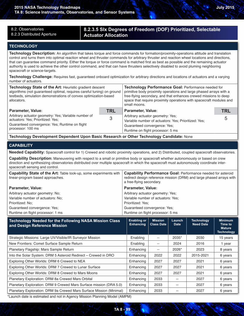
2015 NASA Technology RoadmapsTA 8: Science Instruments, Observatories, and Sensor Systems
July 2015
TA 8 - 99
8.2. Observatories8.2.3 Distributed Aperture
8.2.3.5 SIx Degrees of Freedom (DOF) Prioritized, Selectable Actuator Allocation
TECHNOLOGY
Technology Description: An algorithm that takes torque and force commands for formation/proximity-operations attitude and translation control and turns them into optimal reaction wheel and thruster commands for arbitrary thruster and reaction wheel locations and directions, that can guarantee command priority. Either the torque or force command is matched first as best as possible and the remaining actuator authority is used to achieve the other control command, and that can have thrusters selectively disabled to avoid pluming neighboring spacecraft or science-targets.Technology Challenge: Requires fast, guaranteed onboard optimization for arbitrary directions and locations of actuators and a varying number of actuators.Technology State of the Art: Heuristic gradient descent algorithms (not guaranteed optimal, requires careful tuning) on groundtestbeds, simulation demonstrations of convex optimization-based allocators.
Parameter, Value: Arbitrary actuator geometry: Yes; Variable number of actuators: Yes; Prioritized: Yes;Guaranteed convergence: Yes; Runtime on flight processor: 100 ms
TRL3
Technology Performance Goal: Performance needed for primitive body proximity operations and large phased arrays with a
free-flying secondary, and that enhances crewed missions to deep space that require proximity operations with spacecraft modules and small moons.Parameter, Value: Arbitrary actuator geometry: Yes;Variable number of actuators: Yes; Prioritized: Yes;Guaranteed convergence: Yes;Runtime on flight processor: 5 ms
TRL5
Technology Development Dependent Upon Basic Research or Other Technology Candidate: None
CAPABILITYNeeded Capability: Spacecraft control for 1) Crewed and robotic proximity operations, and 2) Distributed, coupled spacecraft observatories.Capability Description: Maneuvering with respect to a small or primitive body or spacecraft whether autonomously or based on crew direction and synthesizing observatories distributed over multiple spacecraft in which the spacecraft must autonomously coordinate inter-spacecraft sensing and control.Capability State of the Art: Table look-up, some experiments with linear-program based approaches.
Parameter, Value: Arbitrary actuator geometry: No;Variable number of actuators: No;Prioritized: No;Guaranteed convergence: Yes;Runtime on flight processor: 1 ms
Capability Performance Goal: Performance needed for asteroid redirect design reference mission (DRM) and large phased arrays with a free-flying secondary.Parameter, Value: Arbitrary actuator geometry: Yes;Variable number of actuators: Yes;Prioritized: Yes;Guaranteed convergence: Yes;Runtime on flight processor: 5 ms
Technology Needed for the Following NASA Mission Class and Design Reference Mission
Enabling or Enhancing
Mission Class Date
Launch Date
Technology Need Date
Minimum Time to Mature
Technology
Strategic Missions: Large UV/Visible/IR Surveyor Mission Enabling -- 2035* 2030 15 yearsNew Frontiers: Comet Surface Sample Return Enabling -- 2024 2016 1 yearPlanetary Flagship: Mars Sample Return Enhancing -- 2026* 2023 8 yearsInto the Solar System: DRM 5 Asteroid Redirect – Crewed in DRO Enhancing 2022 2022 2015-2021 6 yearsExploring Other Worlds: DRM 6 Crewed to NEA Enhancing 2027 2027 2021 6 yearsExploring Other Worlds: DRM 7 Crewed to Lunar Surface Enhancing 2027 2027 2021 6 yearsExploring Other Worlds: DRM 8 Crewed to Mars Moons Enhancing 2027 2027 2021 6 yearsPlanetary Exploration: DRM 8a Crewed Mars Orbital Enhancing 2033 -- 2027 6 yearsPlanetary Exploration: DRM 9 Crewed Mars Surface mission (DRA 5.0) Enhancing 2033 -- 2027 6 yearsPlanetary Exploration: DRM 9a Crewed Mars Surface Mission (Minimal) Enhancing 2033 -- 2027 6 years
*Launch date is estimated and not in Agency Mission Planning Model (AMPM)
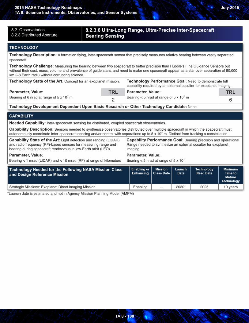
2015 NASA Technology RoadmapsTA 8: Science Instruments, Observatories, and Sensor Systems
July 2015
TA 8 - 100
8.2. Observatories8.2.3 Distributed Aperture
8.2.3.6 Ultra-Long Range, Ultra-Precise Inter-Spacecraft Bearing Sensing
TECHNOLOGY
Technology Description: A formation flying, inter-spacecraft sensor that precisely measures relative bearing between vastly separated spacecraft.Technology Challenge: Measuring the bearing between two spacecraft to better precision than Hubble’s Fine Guidance Sensors but without their cost, mass, volume and prevalence of guide stars, and need to make one spacecraft appear as a star over separation of 50,000 km (~8 Earth radii) without corrupting science.Technology State of the Art: Concept for an exoplanet mission.
Parameter, Value: Bearing of 6 nrad at range of 5 x 10⁷ m
TRL2
Technology Performance Goal: Need to demonstrate full capability required by an external occulter for exoplanet imaging.Parameter, Value: Bearing < 5 nrad at range of 5 x 10⁷ m
TRL6
Technology Development Dependent Upon Basic Research or Other Technology Candidate: None
CAPABILITYNeeded Capability: Inter-spacecraft sensing for distributed, coupled spacecraft observatories.Capability Description: Sensors needed to synthesize observatories distributed over multiple spacecraft in which the spacecraft must autonomously coordinate inter-spacecraft sensing and/or control with separations up to 5 x 10⁷ m. Distinct from tracking a constellation.Capability State of the Art: Light detection and ranging (LIDAR) and radio frequency (RF)-based sensors for measuring range and bearing during spacecraft rendezvous in low-Earth orbit (LEO).Parameter, Value: Bearing < 1 mrad (LIDAR) and < 10 mrad (RF) at range of kilometers
Capability Performance Goal: Bearing precision and operational Range needed to synthesize an external occulter for exoplanet imaging.Parameter, Value: Bearing < 5 nrad at range of 5 x 10⁷
Technology Needed for the Following NASA Mission Class and Design Reference Mission
Enabling or Enhancing
Mission Class Date
Launch Date
Technology Need Date
Minimum Time to Mature
Technology
Strategic Missions: Exoplanet Direct Imaging Mission Enabling -- 2030* 2025 10 years
*Launch date is estimated and not in Agency Mission Planning Model (AMPM)
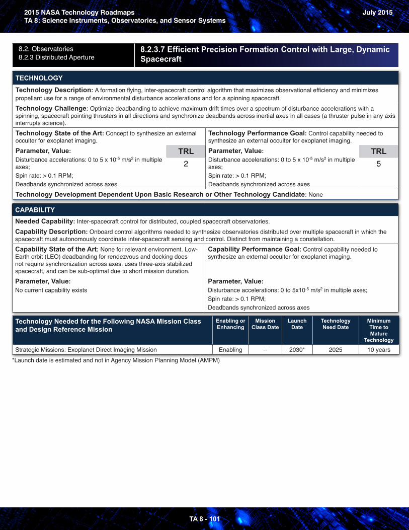
2015 NASA Technology RoadmapsTA 8: Science Instruments, Observatories, and Sensor Systems
July 2015
TA 8 - 101
8.2. Observatories8.2.3 Distributed Aperture
8.2.3.7 Efficient Precision Formation Control with Large, DynamicSpacecraft
TECHNOLOGY
Technology Description: A formation flying, inter-spacecraft control algorithm that maximizes observational efficiency and minimizes propellant use for a range of environmental disturbance accelerations and for a spinning spacecraft.Technology Challenge: Optimize deadbanding to achieve maximum drift times over a spectrum of disturbance accelerations with a spinning, spacecraft pointing thrusters in all directions and synchronize deadbands across inertial axes in all cases (a thruster pulse in any axis interrupts science).Technology State of the Art: Concept to synthesize an external occulter for exoplanet imaging.Parameter, Value: Disturbance accelerations: 0 to 5 x 10⁻⁵ m/s2 in multiple axes;Spin rate: > 0.1 RPM;Deadbands synchronized across axes
TRL2
Technology Performance Goal: Control capability needed to synthesize an external occulter for exoplanet imaging.Parameter, Value: Disturbance accelerations: 0 to 5 x 10⁻⁵ m/s2 in multiple axes;Spin rate: > 0.1 RPM;Deadbands synchronized across axes
TRL5
Technology Development Dependent Upon Basic Research or Other Technology Candidate: None
CAPABILITYNeeded Capability: Inter-spacecraft control for distributed, coupled spacecraft observatories.Capability Description: Onboard control algorithms needed to synthesize observatories distributed over multiple spacecraft in which the spacecraft must autonomously coordinate inter-spacecraft sensing and control. Distinct from maintaining a constellation.Capability State of the Art: None for relevant environment. Low-Earth orbit (LEO) deadbanding for rendezvous and docking does not require synchronization across axes, uses three-axis stabilized spacecraft, and can be sub-optimal due to short mission duration.Parameter, Value: No current capability exists
Capability Performance Goal: Control capability needed to synthesize an external occulter for exoplanet imaging.
Parameter, Value: Disturbance accelerations: 0 to 5x10⁻⁵ m/s2 in multiple axes;Spin rate: > 0.1 RPM;Deadbands synchronized across axes
Technology Needed for the Following NASA Mission Class and Design Reference Mission
Enabling or Enhancing
Mission Class Date
Launch Date
Technology Need Date
Minimum Time to Mature
Technology
Strategic Missions: Exoplanet Direct Imaging Mission Enabling -- 2030* 2025 10 years*Launch date is estimated and not in Agency Mission Planning Model (AMPM)
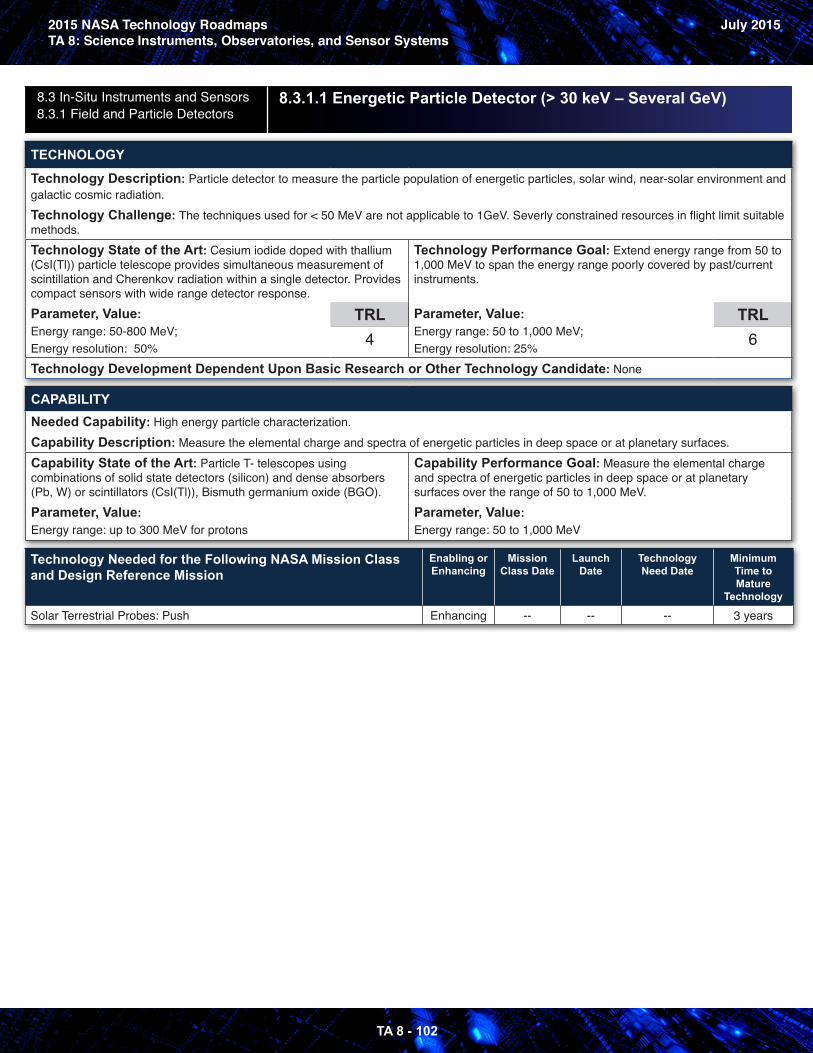
2015 NASA Technology RoadmapsTA 8: Science Instruments, Observatories, and Sensor Systems
July 2015
TA 8 - 102
8.3 In-Situ Instruments and Sensors8.3.1 Field and Particle Detectors
8.3.1.1 Energetic Particle Detector (> 30 keV – Several GeV)
TECHNOLOGY
Technology Description: Particle detector to measure the particle population of energetic particles, solar wind, near-solar environment and galactic cosmic radiation.Technology Challenge: The techniques used for < 50 MeV are not applicable to 1GeV. Severly constrained resources in flight limit suitable methods. Technology State of the Art: Cesium iodide doped with thallium (CsI(Tl)) particle telescope provides simultaneous measurement of scintillation and Cherenkov radiation within a single detector. Provides compact sensors with wide range detector response.Parameter, Value: Energy range: 50-800 MeV;Energy resolution: 50%
TRL4
Technology Performance Goal: Extend energy range from 50 to 1,000 MeV to span the energy range poorly covered by past/current instruments.
Parameter, Value: Energy range: 50 to 1,000 MeV;Energy resolution: 25%
TRL6
Technology Development Dependent Upon Basic Research or Other Technology Candidate: None
CAPABILITYNeeded Capability: High energy particle characterization.Capability Description: Measure the elemental charge and spectra of energetic particles in deep space or at planetary surfaces.Capability State of the Art: Particle T- telescopes using combinations of solid state detectors (silicon) and dense absorbers (Pb, W) or scintillators (CsI(Tl)), Bismuth germanium oxide (BGO).Parameter, Value: Energy range: up to 300 MeV for protons
Capability Performance Goal: Measure the elemental charge and spectra of energetic particles in deep space or at planetary surfaces over the range of 50 to 1,000 MeV.Parameter, Value: Energy range: 50 to 1,000 MeV
Technology Needed for the Following NASA Mission Class and Design Reference Mission
Enabling or Enhancing
Mission Class Date
Launch Date
Technology Need Date
Minimum Time to Mature
Technology
Solar Terrestrial Probes: Push Enhancing -- -- -- 3 years
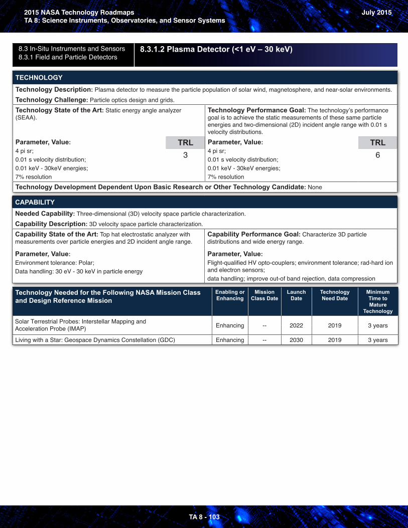
2015 NASA Technology RoadmapsTA 8: Science Instruments, Observatories, and Sensor Systems
July 2015
TA 8 - 103
8.3 In-Situ Instruments and Sensors8.3.1 Field and Particle Detectors
8.3.1.2 Plasma Detector (<1 eV – 30 keV)
TECHNOLOGY
Technology Description: Plasma detector to measure the particle population of solar wind, magnetosphere, and near-solar environments.Technology Challenge: Particle optics design and grids.Technology State of the Art: Static energy angle analyzer (SEAA).
Parameter, Value: 4 pi sr;0.01 s velocity distribution;0.01 keV - 30keV energies;7% resolution
TRL3
Technology Performance Goal: The technology’s performance goal is to achieve the static measurements of these same particle energies and two-dimensional (2D) incident angle range with 0.01 s velocity distributions.Parameter, Value: 4 pi sr;0.01 s velocity distribution;0.01 keV - 30keV energies;7% resolution
TRL6
Technology Development Dependent Upon Basic Research or Other Technology Candidate: None
CAPABILITYNeeded Capability: Three-dimensional (3D) velocity space particle characterization.Capability Description: 3D velocity space particle characterization.Capability State of the Art: Top hat electrostatic analyzer with measurements over particle energies and 2D incident angle range.
Parameter, Value: Environment tolerance: Polar;Data handling: 30 eV - 30 keV in particle energy
Capability Performance Goal: Characterize 3D particle distributions and wide energy range.
Parameter, Value: Flight-qualified HV opto-couplers; environment tolerance; rad-hard ion and electron sensors;data handling; improve out-of band rejection, data compression
Technology Needed for the Following NASA Mission Class and Design Reference Mission
Enabling or Enhancing
Mission Class Date
Launch Date
Technology Need Date
Minimum Time to Mature
Technology
Solar Terrestrial Probes: Interstellar Mapping and Acceleration Probe (IMAP) Enhancing -- 2022 2019 3 years
Living with a Star: Geospace Dynamics Constellation (GDC) Enhancing -- 2030 2019 3 years
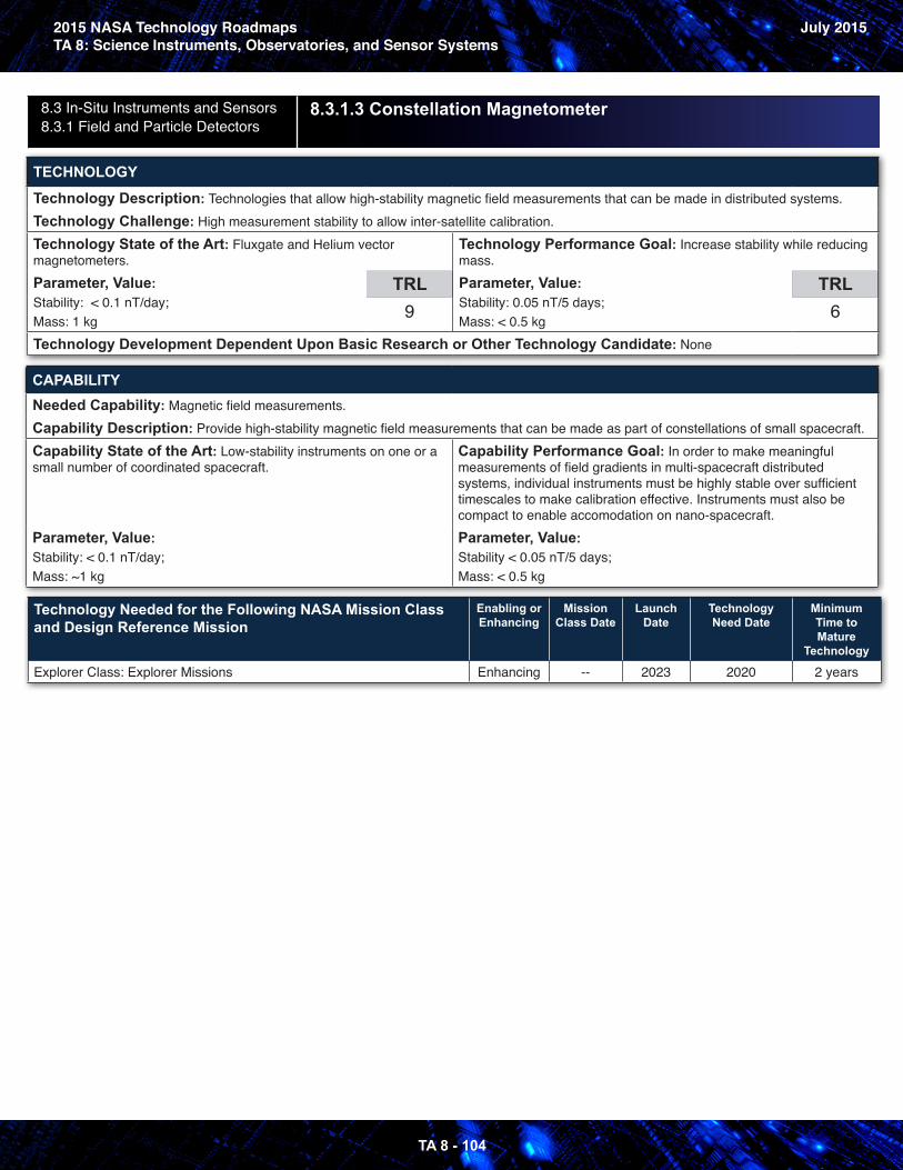
2015 NASA Technology RoadmapsTA 8: Science Instruments, Observatories, and Sensor Systems
July 2015
TA 8 - 104
8.3 In-Situ Instruments and Sensors8.3.1 Field and Particle Detectors
8.3.1.3 Constellation Magnetometer
TECHNOLOGY
Technology Description: Technologies that allow high-stability magnetic field measurements that can be made in distributed systems.Technology Challenge: High measurement stability to allow inter-satellite calibration.Technology State of the Art: Fluxgate and Helium vector magnetometers.Parameter, Value: Stability: < 0.1 nT/day; Mass: 1 kg
TRL9
Technology Performance Goal: Increase stability while reducing mass.Parameter, Value: Stability: 0.05 nT/5 days;Mass: < 0.5 kg
TRL6
Technology Development Dependent Upon Basic Research or Other Technology Candidate: None
CAPABILITYNeeded Capability: Magnetic field measurements.Capability Description: Provide high-stability magnetic field measurements that can be made as part of constellations of small spacecraft.Capability State of the Art: Low-stability instruments on one or a small number of coordinated spacecraft.
Parameter, Value: Stability: < 0.1 nT/day;Mass: ~1 kg
Capability Performance Goal: In order to make meaningful measurements of field gradients in multi-spacecraft distributed systems, individual instruments must be highly stable over sufficient timescales to make calibration effective. Instruments must also be compact to enable accomodation on nano-spacecraft.Parameter, Value: Stability < 0.05 nT/5 days;Mass: < 0.5 kg
Technology Needed for the Following NASA Mission Class and Design Reference Mission
Enabling or Enhancing
Mission Class Date
Launch Date
Technology Need Date
Minimum Time to Mature
Technology
Explorer Class: Explorer Missions Enhancing -- 2023 2020 2 years
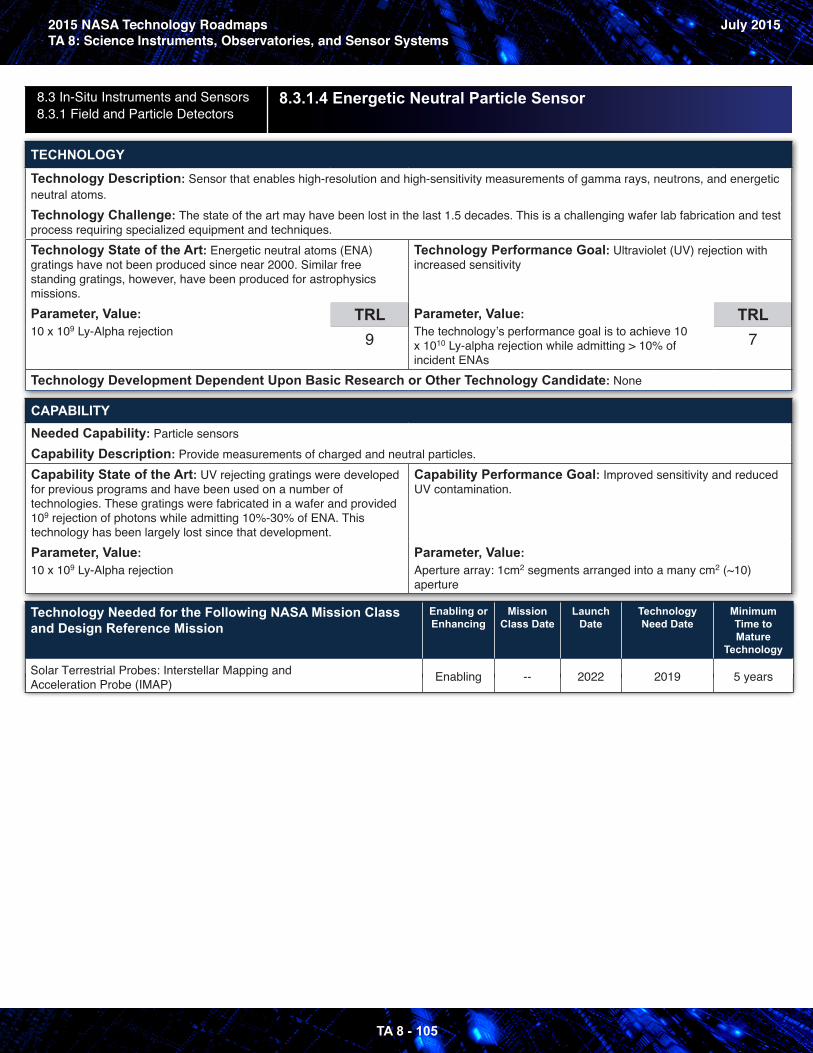
2015 NASA Technology RoadmapsTA 8: Science Instruments, Observatories, and Sensor Systems
July 2015
TA 8 - 105
8.3 In-Situ Instruments and Sensors8.3.1 Field and Particle Detectors
8.3.1.4 Energetic Neutral Particle Sensor
TECHNOLOGY
Technology Description: Sensor that enables high-resolution and high-sensitivity measurements of gamma rays, neutrons, and energetic neutral atoms.Technology Challenge: The state of the art may have been lost in the last 1.5 decades. This is a challenging wafer lab fabrication and test process requiring specialized equipment and techniques. Technology State of the Art: Energetic neutral atoms (ENA) gratings have not been produced since near 2000. Similar free standing gratings, however, have been produced for astrophysics missions.Parameter, Value: 10 x 109 Ly-Alpha rejection
TRL9
Technology Performance Goal: Ultraviolet (UV) rejection with increased sensitivity
Parameter, Value: The technology’s performance goal is to achieve 10 x 1010 Ly-alpha rejection while admitting > 10% of incident ENAs
TRL7
Technology Development Dependent Upon Basic Research or Other Technology Candidate: None
CAPABILITYNeeded Capability: Particle sensorsCapability Description: Provide measurements of charged and neutral particles.Capability State of the Art: UV rejecting gratings were developed for previous programs and have been used on a number of technologies. These gratings were fabricated in a wafer and provided 109 rejection of photons while admitting 10%-30% of ENA. This technology has been largely lost since that development.Parameter, Value: 10 x 109 Ly-Alpha rejection
Capability Performance Goal: Improved sensitivity and reduced UV contamination.
Parameter, Value: Aperture array: 1cm2 segments arranged into a many cm2 (~10) aperture
Technology Needed for the Following NASA Mission Class and Design Reference Mission
Enabling or Enhancing
Mission Class Date
Launch Date
Technology Need Date
Minimum Time to Mature
Technology
Solar Terrestrial Probes: Interstellar Mapping and Acceleration Probe (IMAP) Enabling -- 2022 2019 5 years
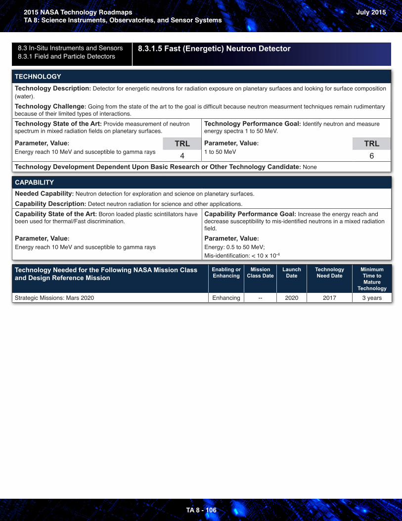
2015 NASA Technology RoadmapsTA 8: Science Instruments, Observatories, and Sensor Systems
July 2015
TA 8 - 106
8.3 In-Situ Instruments and Sensors8.3.1 Field and Particle Detectors
8.3.1.5 Fast (Energetic) Neutron Detector
TECHNOLOGY
Technology Description: Detector for energetic neutrons for radiation exposure on planetary surfaces and looking for surface composition (water).Technology Challenge: Going from the state of the art to the goal is difficult because neutron measurment techniques remain rudimentary because of their limited types of interactions.Technology State of the Art: Provide measurement of neutron spectrum in mixed radiation fields on planetary surfaces.
Parameter, Value: Energy reach 10 MeV and susceptible to gamma rays
TRL4
Technology Performance Goal: Identify neutron and measure energy spectra 1 to 50 MeV.
Parameter, Value: 1 to 50 MeV
TRL6
Technology Development Dependent Upon Basic Research or Other Technology Candidate: None
CAPABILITYNeeded Capability: Neutron detection for exploration and science on planetary surfaces.Capability Description: Detect neutron radiation for science and other applications.Capability State of the Art: Boron loaded plastic scintillators have been used for thermal/Fast discrimination.
Parameter, Value: Energy reach 10 MeV and susceptible to gamma rays
Capability Performance Goal: Increase the energy reach and decrease susceptibility to mis-identified neutrons in a mixed radiation field.Parameter, Value: Energy: 0.5 to 50 MeV; Mis-identification: < 10 x 10-4
Technology Needed for the Following NASA Mission Class and Design Reference Mission
Enabling or Enhancing
Mission Class Date
Launch Date
Technology Need Date
Minimum Time to Mature
Technology
Strategic Missions: Mars 2020 Enhancing -- 2020 2017 3 years
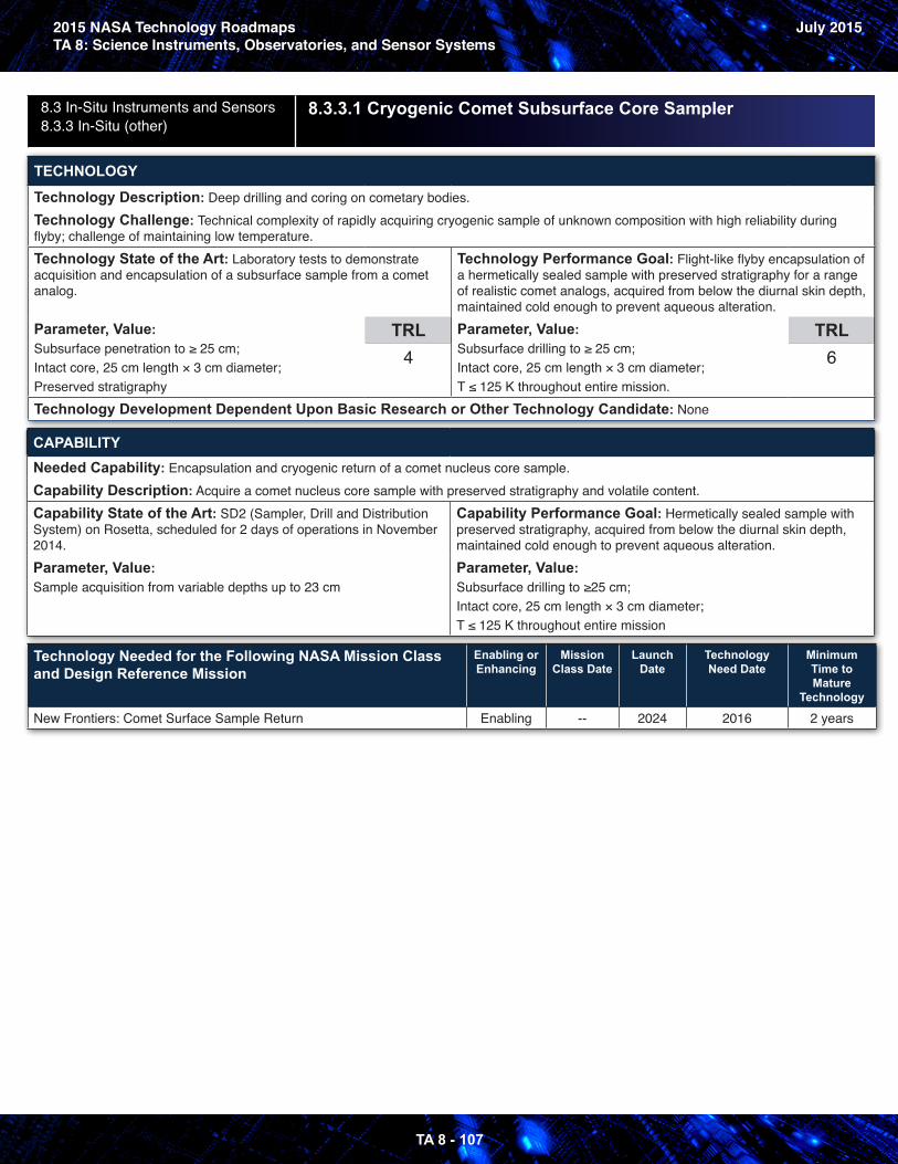
2015 NASA Technology RoadmapsTA 8: Science Instruments, Observatories, and Sensor Systems
July 2015
TA 8 - 107
8.3 In-Situ Instruments and Sensors8.3.3 In-Situ (other)
8.3.3.1 Cryogenic Comet Subsurface Core Sampler
TECHNOLOGY
Technology Description: Deep drilling and coring on cometary bodies.Technology Challenge: Technical complexity of rapidly acquiring cryogenic sample of unknown composition with high reliability during flyby; challenge of maintaining low temperature.Technology State of the Art: Laboratory tests to demonstrate acquisition and encapsulation of a subsurface sample from a comet analog.
Parameter, Value: Subsurface penetration to ≥ 25 cm;Intact core, 25 cm length × 3 cm diameter;Preserved stratigraphy
TRL4
Technology Performance Goal: Flight-like flyby encapsulation of a hermetically sealed sample with preserved stratigraphy for a range of realistic comet analogs, acquired from below the diurnal skin depth, maintained cold enough to prevent aqueous alteration.Parameter, Value: Subsurface drilling to ≥ 25 cm;Intact core, 25 cm length × 3 cm diameter;T ≤ 125 K throughout entire mission.
TRL6
Technology Development Dependent Upon Basic Research or Other Technology Candidate: None
CAPABILITYNeeded Capability: Encapsulation and cryogenic return of a comet nucleus core sample.Capability Description: Acquire a comet nucleus core sample with preserved stratigraphy and volatile content.Capability State of the Art: SD2 (Sampler, Drill and Distribution System) on Rosetta, scheduled for 2 days of operations in November 2014.Parameter, Value: Sample acquisition from variable depths up to 23 cm
Capability Performance Goal: Hermetically sealed sample with preserved stratigraphy, acquired from below the diurnal skin depth, maintained cold enough to prevent aqueous alteration.Parameter, Value: Subsurface drilling to ≥25 cm;Intact core, 25 cm length × 3 cm diameter;T ≤ 125 K throughout entire mission
Technology Needed for the Following NASA Mission Class and Design Reference Mission
Enabling or Enhancing
Mission Class Date
Launch Date
Technology Need Date
Minimum Time to Mature
Technology
New Frontiers: Comet Surface Sample Return Enabling -- 2024 2016 2 years
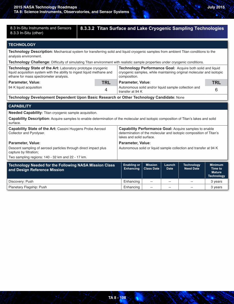
2015 NASA Technology RoadmapsTA 8: Science Instruments, Observatories, and Sensor Systems
July 2015
TA 8 - 108
8.3 In-Situ Instruments and Sensors8.3.3 In-Situ (other)
8.3.3.2 Titan Surface and Lake Cryogenic Sampling Technologies
TECHNOLOGY
Technology Description: Mechanical system for transferring solid and liquid cryogenic samples from ambient Titan conditions to the analysis environment. Technology Challenge: Difficulty of simulating Titan environment with realistic sample properties under cryogenic conditions. Technology State of the Art: Laboratory prototype cryogenic liquid acquisition system with the ability to ingest liquid methane and ethane for mass spectrometer analysis.Parameter, Value: 94 K liquid acquisition
TRL4
Technology Performance Goal: Acquire both solid and liquid cryogenic samples, while maintaining original molecular and isotopic composition.Parameter, Value: Autonomous solid and/or liquid sample collection and transfer at 94 K
TRL6
Technology Development Dependent Upon Basic Research or Other Technology Candidate: None
CAPABILITYNeeded Capability: Titan cryogenic sample acquisition.Capability Description: Acquire samples to enable determination of the molecular and isotopic composition of Titan’s lakes and solid surface.Capability State of the Art: Cassini Huygens Probe Aerosol Collector and Pyrolyser.
Parameter, Value: Descent sampling of aerosol particles through direct impact plus capture by filtration;Two sampling regions: 140 - 32 km and 22 - 17 km.
Capability Performance Goal: Acquire samples to enable determination of the molecular and isotopic composition of Titan’s lakes and solid surface.Parameter, Value: Autonomous solid or liquid sample collection and transfer at 94 K
Technology Needed for the Following NASA Mission Class and Design Reference Mission
Enabling or Enhancing
Mission Class Date
Launch Date
Technology Need Date
Minimum Time to Mature
Technology
Discovery: Push Enhancing -- -- -- 3 yearsPlanetary Flagship: Push Enhancing -- -- -- 3 years
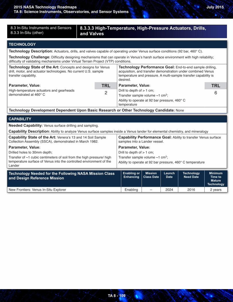
2015 NASA Technology RoadmapsTA 8: Science Instruments, Observatories, and Sensor Systems
July 2015
TA 8 - 109
8.3 In-Situ Instruments and Sensors8.3.3 In-Situ (other)
8.3.3.3 High-Temperature, High-Pressure Actuators, Drills, and Valves
TECHNOLOGY
Technology Description: Actuators, drills, and valves capable of operating under Venus surface conditions (92 bar, 460° C).Technology Challenge: Difficulty designing mechanisms that can operate in Venus’s harsh surface environment with high reliability; difficulty of validating mechanisms under Virtual Terrain Project (VTP) conditions.Technology State of the Art: Concepts and designs for Venus drill, motor, and actuator technologies. No current U.S. sample transfer capability.
Parameter, Value: High-temperature actuators and gearheads demonstrated at 460° C
TRL2
Technology Performance Goal: End-to-end sample drilling, acquisition, and transfer demonstration under combined Venus temperature and pressure. A multi-sample transfer capability is desired.Parameter, Value: Drill to depth of > 1 cm;Transfer sample volume ~1 cm3;Ability to operate at 92 bar pressure, 460° C temperature
TRL6
Technology Development Dependent Upon Basic Research or Other Technology Candidate: None
CAPABILITYNeeded Capability: Venus surface drilling and sampling.Capability Description: Ability to analyze Venus surface samples inside a Venus lander for elemental chemistry, and mineralogyCapability State of the Art: Venera’s 13 and 14 Soil Sample Collection Assembly (SSCA), demonstrated in March 1982.Parameter, Value: Drilled holes to 30mm depth;Transfer of ~1 cubic centimeters of soil from the high pressure/ high temperature surface of Venus into the controlled environment of the Lander
Capability Performance Goal: Ability to transfer Venus surface samples into a Lander vessel.Parameter, Value: Drill to depth of > 1 cm;Transfer sample volume ~1 cm3;Ability to operate at 92 bar pressure, 460° C temperature
Technology Needed for the Following NASA Mission Class and Design Reference Mission
Enabling or Enhancing
Mission Class Date
Launch Date
Technology Need Date
Minimum Time to Mature
Technology
New Frontiers: Venus In-Situ Explorer Enabling -- 2024 2016 2 years
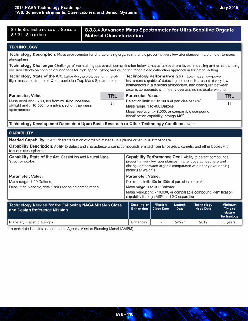
2015 NASA Technology RoadmapsTA 8: Science Instruments, Observatories, and Sensor Systems
July 2015
TA 8 - 110
8.3 In-Situ Instruments and Sensors8.3.3 In-Situ (other)
8 .3 .3 .4 Advanced Mass Spectrometer for Ultra-Sensitive Organic Material Characterization
TECHNOLOGY
Technology Description: Mass spectrometer for characterizing organic materials present at very low abundances in a plume or tenuous atmosphere.Technology Challenge: Challenge of maintaining spacecraft contamination below tenuous atmosphere levels; modeling and understanding collision effects on species abundances for high-speed flybys; and validating models and calibration approach in terrestrial settingTechnology State of the Art: Laboratory prototypes for time-of-flight mass spectrometer, Quadrupole Ion Trap Mass Spectrometer.
Parameter, Value: Mass resolution: > 30,000 from multi-bounce time-of-flight and > 10,000 from advanced ion trap mass spectrometers
TRL5
Technology Performance Goal: Low-mass, low-power instrument capable of detecting compounds present at very low abundances in a tenuous atmosphere, and distinguish between organic compounds with nearly overlapping molecular weights.Parameter, Value: Detection limit: 0.1 to 100s of particles per cm3;Mass range: 1 to 400 Daltons;Mass resolution: > 8,000, or comparable compound identification capability through MSn.
TRL6
Technology Development Dependent Upon Basic Research or Other Technology Candidate: None
CAPABILITYNeeded Capability: In-situ characterization of organic material in a plume or tenuous atmosphere.Capability Description: Ability to detect and characterize organic compounds emitted from Enceladus, comets, and other bodies with tenuous atmospheres.Capability State of the Art: Cassini Ion and Neutral Mass Spectrometeter.
Parameter, Value: Mass range: 1-99 Daltons;Resolution: variable, with 1 amu scanning across range
Capability Performance Goal: Ability to detect compounds present at very low abundances in a tenuous atmosphere and distinguish between organic compounds with nearly overlapping molecular weights.Parameter, Value: Detection limit: 10s to 100s of particles per cm3;Mass range: 1 to 400 Daltons;Mass resolution: > 10,000, or comparable compound identification capability through MSn, and GC separation
Technology Needed for the Following NASA Mission Class and Design Reference Mission
Enabling or Enhancing
Mission Class Date
Launch Date
Technology Need Date
Minimum Time to Mature
Technology
Planetary Flagship: Europa Enhancing -- 2022* 2019 5 years*Launch date is estimated and not in Agency Mission Planning Model (AMPM)
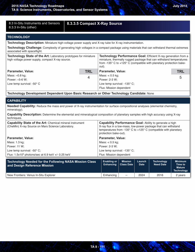
2015 NASA Technology RoadmapsTA 8: Science Instruments, Observatories, and Sensor Systems
July 2015
TA 8 - 111
8.3 In-Situ Instruments and Sensors8.3.3 In-Situ (other)
8.3.3.5 Compact X-Ray Source
TECHNOLOGY
Technology Description: Miniature high-voltage power supply and X-ray tube for X-ray instrumentation.Technology Challenge: Complexity of generating high voltages in a compact package using materials that can withstand thermal extremes associated with spaceflight.Technology State of the Art: Laboratory prototypes for miniature high voltage power supply, compact X-ray source.
Parameter, Value: Mass: ~0.8 kg;Power: ~5-6 W;Low temp survival: -50° C
TRL4
Technology Performance Goal: Efficient X-ray generation from a miniature, thermally rugged package that can withstand temperatures from -135° C to +125° C (compatible with planetary protection bake-out).Parameter, Value: Mass: < 0.5 kg;Power: 2-3 W;Low temp survival: -135° C;Flux: Mission dependent
TRL5
Technology Development Dependent Upon Basic Research or Other Technology Candidate: None
CAPABILITYNeeded Capability: Reduce the mass and power of X-ray instrumentation for surface compositional analyses (elemental chemistry, mineralogy).Capability Description: Determine the elemental and mineralogical composition of planetary samples with high accuracy using X-ray techniques.Capability State of the Art: Chemical mineral instrument (CheMin) X-ray Source on Mars Science Laboratory.
Parameter, Value: Mass: 1.3 kg;Power: 11 W;Low temp survival: -50° C;Flux: 1.5x10⁵ photons/sec at 6.9 keV +/- 0.25 keV
Capability Performance Goal: Ability to generate a high X-ray flux in a low-mass, low-power package that can withstand temperatures from -135° C to +125° C (compatible with planetary protection bake-out).Parameter, Value: Mass: < 0.5 kg;Power: 2-3 W;Low temp survival: -135° C;Flux: Mission dependent
Technology Needed for the Following NASA Mission Class and Design Reference Mission
Enabling or Enhancing
Mission Class Date
Launch Date
Technology Need Date
Minimum Time to Mature
Technology
New Frontiers: Venus In-Situ Explorer Enhancing -- 2024 2016 2 years

2015 NASA Technology RoadmapsTA 8: Science Instruments, Observatories, and Sensor Systems
July 2015
TA 8 - 112
8.3 In-Situ Instruments and Sensors8.3.3 In-Situ (other)
8.3.3.6 Wet Chemistry Technologies for Life Detection
TECHNOLOGY
Technology Description: Wet chemical analysis approaches that can identify in-situ biosignatures such as, amino acid chirality, and carboxylic acid chain length distributions.Technology Challenge: Difficulty storing and manipulating fluids and performing complex chemical analyses under planetary conditions; challenges with contamination control requirements and planetary protection compliance.Technology State of the Art: Miscellaneous wet chemistry laboratory prototypes for organic compound detection, but no end-to-end autonomous, flight-qualified system.Parameter, Value: Microfluidic capillary electrophoresis with laser-induced fluorescence detection for ~1 ppb detection of amino acid chirality. No front-end extraction and injection system.
TRL3
Technology Performance Goal: Detect biosignatures such as amino acid chirality and carboxylic acid chain length in planetary materials with high confidence in a low mass, low power instrument.Parameter, Value: Examples: amino acid chirality detection (~1 ppb detection limits);Carboxylic acid chain length detection (~1 ppb detection limits);Mass: ~ 5 kg;Power: ~20 W
TRL5
Technology Development Dependent Upon Basic Research or Other Technology Candidate: None
CAPABILITYNeeded Capability: Life detection.Capability Description: Determine whether complex organic molecules and possibly life emerged on other planetary bodies (e.g. Enceladus, Europa, and Mars).Capability State of the Art: Life Marker Chip, descoped from 2018 ExoMars.Parameter, Value: Multiplexed immunoassay to detect biomarkers and other organics in water-based solvent extract: four samples with 25 target analytes each
Capability Performance Goal: Ability to detect biosignatures in planetary materials with high confidence.Parameter, Value: Examples: Measure amino acid chirality (~1 ppb abundance levels);Measure carboxylic acid chain length (~1 ppb abundance levels);Mass: ~ 5 kg;Power: ~20 W
Technology Needed for the Following NASA Mission Class and Design Reference Mission
Enabling or Enhancing
Mission Class Date
Launch Date
Technology Need Date
Minimum Time to Mature
Technology
Discovery: Discovery 14 Enabling -- 2023 2020 3 years
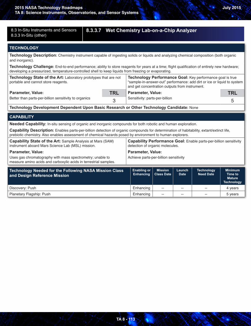
2015 NASA Technology RoadmapsTA 8: Science Instruments, Observatories, and Sensor Systems
July 2015
TA 8 - 113
8.3 In-Situ Instruments and Sensors8.3.3 In-Situ (other)
8.3.3.7 Wet Chemistry Lab-on-a-Chip Analyzer
TECHNOLOGY
Technology Description: Chemistry instrument capable of ingesting solids or liquids and analyzing chemical composition (both organic and inorganic).Technology Challenge: End-to-end performance; ability to store reagents for years at a time; flight qualification of entirely new hardware; developing a pressurized, temperature-controlled shell to keep liquids from freezing or evaporating.Technology State of the Art: Laboratory prototypes that are not portable and cannot store reagents.
Parameter, Value: Better than parts-per-billion sensitivity to organics
TRL3
Technology Performance Goal: Key performance goal is true “sample-in-answer-out” performance: add dirt or ice or liquid to system and get concentration outputs from instrument.Parameter, Value: Sensitivity: parts-per-billion
TRL5
Technology Development Dependent Upon Basic Research or Other Technology Candidate: None
CAPABILITYNeeded Capability: In-situ sensing of organic and inorganic compounds for both robotic and human exploration.Capability Description: Enables parts-per-billion detection of organic compounds for determination of habitability, extant/extinct life, prebiotic chemistry. Also enables assessment of chemical hazards posed by environment to human explorers.Capability State of the Art: Sample Analysis at Mars (SAM) instrument aboard Mars Science Lab (MSL) mission.Parameter, Value: Uses gas chromatography with mass spectrometry; unable to measure amino acids and carboxylic acids in terrestrial samples.
Capability Performance Goal: Enable parts-per-billion sensitivity detection of organic molecules.Parameter, Value: Achieve parts-per-billion sensitivity
Technology Needed for the Following NASA Mission Class and Design Reference Mission
Enabling or Enhancing
Mission Class Date
Launch Date
Technology Need Date
Minimum Time to Mature
Technology
Discovery: Push Enhancing -- -- -- 4 yearsPlanetary Flagship: Push Enhancing -- -- -- 5 years
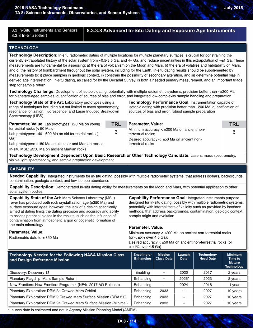
2015 NASA Technology Roadmaps July 2015TA 8: Science Instruments, Observatories, and Sensor Systems
8.3 In-Situ Instruments and Sensors 8.3.3 In-Situ (other)
8.3.3.8 Advanced In-Situ Dating and Exposure Age Instruments
TECHNOLOGY
Technology Description: In-situ radiometric dating of multiple locations for multiple planetary surfaces is crucial for constraining the currently extrapolated history of the solar system from ~0.5-3.5 Ga, and 4+ Ga, and reduce uncertainties in this extrapolation of ~±1 Ga. These measurements are fundamental for assessing: a) the era of volcanism on the Moon and Mars, b) the era of volatiles and habitability on Mars, and c) the history of bombardment throughout the solar system, including for the Earth. In-situ dating results should be supplemented by measurements to: i) place samples in geologic context, ii) constrain the possibility of secondary alteration, and iii) determine potential bias in derived age interpretation. In-situ dating, as called for by the Decadal Survey, is both a needed primary measurement, and an important triage step for sample return. Technology Challenge: Development of isotopic dating, potentially with multiple radiometric systems, precision better than ~±200 Mafor planetary-aged samples, quantification of sources of bias and error, and integrated low-complexity sample handling and preparation Technology State of the Art: Laboratory prototypes using arange of techniques including but not limited to mass spectrometry, resonance ionization, fluorescence, and Laser Induced Breakdown Spectroscopy (LIBS)
Technology Performance Goal: Instrumentation capable ofisotopic dating with precision better than ±200 Ma, quantification ofsources of bias and error, robust sample preparation
Parameter, Value: Lab prototypes: ±20 Ma on youngterrestrial rocks (< 50 Ma); Lab prototypes: ±40 - 600 Ma on old terrestrial rocks (1+ Ga); Lab prototypes: ±180 Ma on old lunar and Martian rocks; In-situ MSL: ±350 Ma on ancient Martian rocks
TRL 3
Parameter, Value: Minimum accuracy < ±200 Ma on ancient non-terrestrial rocks; Desired accuracy < ±50 Ma on ancient non-terrestrial rocks
TRL 6
Technology Development Dependent Upon Basic Research or Other Technology Candidate: Lasers, mass spectrometry, visible light spectroscopy, and sample preparation development
CAPABILITY Needed Capability: Integrated instruments for in-situ dating, possibly with multiple radiometric systems, that address isobars, backgrounds,contamination, geologic context, and low isotope abundance Capability Description: Demonstrated in-situ dating ability for measurements on the Moon and Mars, with potential application to othersolar system bodies Capability State of the Art: Mars Science Laboratroy (MSL) rover has produced both rock crystallization age (±350 Ma) and surface exposure ages; however, the lack of a design specificallyaimed at dating limits the dating precision and accuracy and abilityto assess potential biases in the results, such as the influence of contamination from atmospheric argon or cogenetic formation ofthe main mineralogy
Capability Performance Goal: Integrated instruments purposedesigned for in-situ dating, possibly with multiple radiometric systems,potentially with internal tests of validity such as provided by isochronmethods, that address backgrounds, contamination, geologic context,sample origin and evolution
Parameter, Value: Radiometric date to ± 350 Ma
Parameter, Value: Minimum accuracy < ±200 Ma on ancient non-terrestrial rocks (or < ±5% over 4.5 Ga); Desired accuracy < ±50 Ma on ancient non-terrestrial rocks (or < ±1% over 4.5 Ga)
Technology Needed for the Following NASA Mission Class and Design Reference Mission
Enabling orEnhancing
Mission Class Date
Launch Date
Technology Need Date
Minimum Time to Mature
Technology
Discovery: Discovery 13 Enabling - 2020 2017 2 years Planetary Flagship: Mars Sample Return Enhancing - 2026* 2023 8 years New Frontiers: New Frontiers Program 4 (NF4/~2017 AO Release) Enhancing - 2024 2016 1 year Planetary Exploration: DRM 8a Crewed Mars Orbital Enhancing 2033 - 2027 10 years Planetary Exploration: DRM 9 Crewed Mars Surface Mission (DRA 5.0) Enhancing 2033 - 2027 10 years Planetary Exploration: DRM 9a Crewed Mars Surface Mission (Minimal) Enhancing 2033 - 2027 10 years
*Launch date is estimated and not in Agency Mission Planning Model (AMPM)
TA 8 - 114
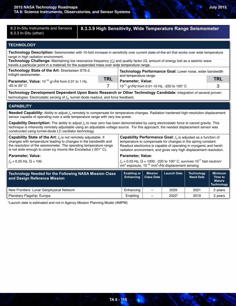
2015 NASA Technology RoadmapsTA 8: Science Instruments, Observatories, and Sensor Systems
July 2015
8.3 In-Situ Instruments and Sensors 8.3.3 In-Situ (other)
8.3.3.9 High Sensitivity, Wide Temperature Range Seismometer
TECHNOLOGY
Technology Description: Seismometer with 10-fold increase in sensitivity over current state-of-the-art that works over wide temperaturerange in high radiation environment.
Technology Challenge: Maintaining low resonance frequency (fo) and quality factor (Q, amount of energy lost as a seismic wave travels a particular point in a material) for the suspended mass over wide temperature range.Technology State of the Art: Streckeisen STS-2, InSight seismometer.
Technology Performance Goal: Lower noise, wider bandwidth and temperature range.
Parameter, Value: 10-10 g/√Hz from 0.01 to 1 Hz, -65 to 20° C
TRL 7
Parameter, Value: 10-11 g/√Hz from 0.01-10 Hz, -220 to 100° C
TRL 3
Technology Development Dependent Upon Basic Research or Other Technology Candidate: Integration of several proven technologies: Electrostatic zeroing of fo, tunnel diode readout, and force feedback.
CAPABILITY Needed Capability: Ability to adjust fo remotely to compensate for temperature changes. Radiation hardened high-resolution displacementsensor capable of operating over a wide temperature range with very low power. Capability Description: The ability to adjust fo to near zero has been demonstrated by using electrostatic force to cancel gravity. This technique is inherently remotely adjustable using an adjustable voltage source. For this approach, the needed displacement sensor wasconstructed using tunnel-diode LC oscillator technology. Capability State of the Art: fo is not remotely adjustable. It changes with temperature leading to changes in the bandwidth andthe resolution of the seismometer. The operating temperature range is not wide enough to cover icy moons like Enceladus (-201° C).
Capability Performance Goal: fo is adjusted as a function oftemperature to compensate for changes in the spring constant.Readout electronics is capable of operating in cryogenic and harshradiation environment, and gives very high displacement resolution.
Parameter, Value: fo = 0.25 Hz, Q = 100.
Parameter, Value: fo = 0.03 Hz, Q = 1000, -220 to 100° C, survives 1017 fast neutron/ cm2 exposure, 10-10 m/s2√Hz displacement sensing.
Technology Needed for the Following NASA Mission Class and Design Reference Mission
Enabling orEnhancing
Mission Class Date
Launch Date Technology Need Date
Minimum Time to Mature
Technology
New Frontiers: Lunar Geophysical Network Enhancing - 2029 2021 2 years Planetary Flagship: Europa Enabling - 2022* 2019 2 years
*Launch date is estimated and not in Agency Mission Planning Model (AMPM)
TA 8 - 115