Schneider Electric OsiSense™ XG Radio Frequency ... · OsiSense XG Radio Frequency Identification...
32
OsiSense ™ XG Radio Frequency Identification System Catalog Simply easy! Courtesy of Steven Engineering, Inc. - (800) 258-9200 - [email protected] - www.stevenengineering.com
Transcript of Schneider Electric OsiSense™ XG Radio Frequency ... · OsiSense XG Radio Frequency Identification...
OsiSense™ XGRadio Frequency Identification System
Catalog
Simply easy!
Courtesy of Steven Engineering, Inc. - (800) 258-9200 - [email protected] - www.stevenengineering.com

Courtesy of Steven Engineering, Inc. - (800) 258-9200 - [email protected] - www.stevenengineering.com

Fully open RFIDMake the most of the openness of the OsiSense XG RFID system. This product range gives you the freedom to choose the tags you wish, and automatically adapts to your network protocol.
This range has many advantages:
3
Choice of tags100% compatible with ISO standard tags (non-locked)
Simplicity and speed30% savings in installation and setup time
Tested and approved100% RoHS compliant; UL, CE, and FCC certified
ContentsSelection guide ........................................................................................................... page 6Introduction, description ............................................................................................. page 8Specifications ............................................................................................................ page 18Catalog numbers ...................................................................................................... page 20Dimensions ............................................................................................................... page 24Connections ............................................................................................................. page 26Operating curves ...................................................................................................... page 28Mounting distances .................................................................................................. page 29Product catalog number index .................................................................................. page 30
Courtesy of Steven Engineering, Inc. - (800) 258-9200 - [email protected] - www.stevenengineering.com
4
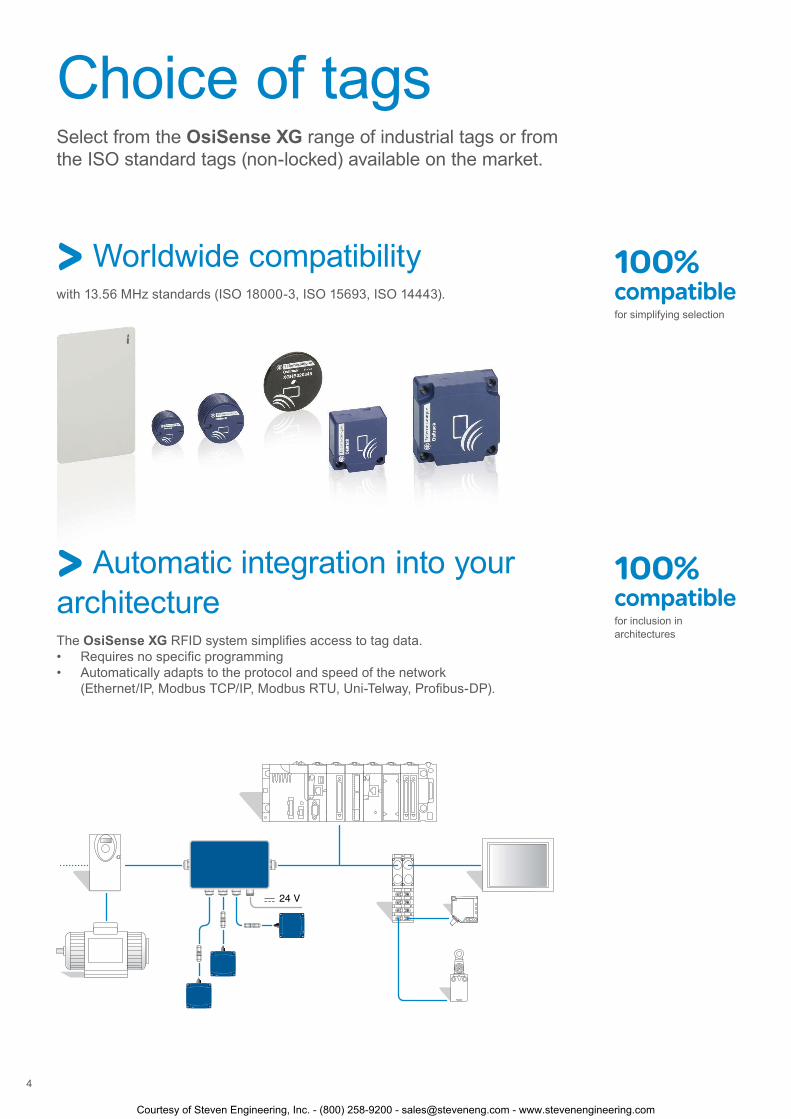
Choice of tagsSelect from the OsiSense XG range of industrial tags or from the ISO standard tags (non-locked) available on the market.
> Worldwide compatibilitywith 13.56 MHz standards (ISO 18000-3, ISO 15693, ISO 14443).
> Automatic integration into your architectureThe OsiSense XG RFID system simplifies access to tag data.• Requires no specific programming• Automatically adapts to the protocol and speed of the network
(Ethernet/IP, Modbus TCP/IP, Modbus RTU, Uni-Telway, Profibus-DP).
100% compatiblefor simplifying selection
100% compatiblefor inclusion in architectures
Courtesy of Steven Engineering, Inc. - (800) 258-9200 - [email protected] - www.stevenengineering.com

Simplicity and speedForget complex connections and configurations. With OsiSense XG, the RFID system is quick and easy to install and set up.
Tested and approvedIdeally suited to a variety of constraints and requirements, the OsiSense XG range has been comprehensively tested both in the laboratory and in the field to help ensure its reliability. The reduced consumption (< 60 mA per station) and the choice of materials for the OsiSense XG range make the products environmentally friendly.
> Easy to installThe station self-adapts to the environment. It fits even in confined spaces, thanks to its compactness (40 x 40 x 15 mm), mounting accessories, and quick cabling.
> Quick to connect and set up 30% savings in installation and setup time
• Use the handheld terminal (XGST2422) for direct access to data in the tags.
Click!
• Connect the station to the PLC, and it’s fully operational. Everything you need is integrated into the product (antenna, RFID controller, and protocol).
• Simply present the configuration badge to set the network address of the station.
100 % RoHs CompliantTelemecanique Sensors brand is committed to reducing the environmental impact of its products
5
Courtesy of Steven Engineering, Inc. - (800) 258-9200 - [email protected] - www.stevenengineering.com

XGCS4901201
XGCS8901201
XGCS4901201 + XGFEC540
XGCS4901201 + XGFEC2525
XGST2422
XGHB320345
XGHB90E340
XGHB444345
XGHB445345
XGHB211345
XGHB221346
1
2
3
4
5
7
XGHB4113466
8
9
10
11
12
XGHB32024613
XGHB44024514
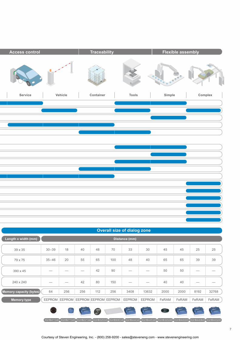
Overall size of dialog zone
Length x width (mm) Distance (mm)
XGCS4901201
XGCS8901201
XGCS4901201+ XGFEC540
XGCS4901201+ XGFEC2525
1
2
3
4
Memory capacity (bytes)5
39 x 35
79 x 75
390 x 45
240 x 240
XGHB44084515
XGHB44324516
64
—
—
35–46
30–39
XGHB411346 XGHB211345 XGHB221346 XGHB320345 XGHB90E340 XGHB444345 XGHB445345 XGHB320246 XGHB440245 XGHB440845 XGHB443245
256
—
—
20
18
256
42
—
55
40
112
80
42
65
48
256
150
90
100
70
3408
—
—
48
33
13632
—
—
40
30
2000
40
50
65
45
2000
40
50
65
45
8192
—
—
39
25
32768
Memory type EEPROM EEPROM EEPROM EEPROM EEPROM EEPROM EEPROM FeRAM FeRAM FeRAM FeRAM
—
—
39
25
Reading system
RFID tags
Material handling Access control Traceability Flexible assembly
Trolley Narrow conveyoror overhead line
Medium widthconveyor Wide conveyor Operator Service Vehicle Container Tools Simple Complex
46
Selection guide
Courtesy of Steven Engineering, Inc. - (800) 258-9200 - [email protected] - www.stevenengineering.com
XGCS4901201
XGCS8901201
XGCS4901201 + XGFEC540
XGCS4901201 + XGFEC2525
XGST2422
XGHB320345
XGHB90E340
XGHB444345
XGHB445345
XGHB211345
XGHB221346
1
2
3
4
5
7
XGHB4113466
8
9
10
11
12
XGHB32024613
XGHB44024514
Overall size of dialog zone
Length x width (mm) Distance (mm)
XGCS4901201
XGCS8901201
XGCS4901201+ XGFEC540
XGCS4901201+ XGFEC2525
1
2
3
4
Memory capacity (bytes)5
39 x 35
79 x 75
390 x 45
240 x 240
XGHB44084515
XGHB44324516
64
—
—
35–46
30–39
XGHB411346 XGHB211345 XGHB221346 XGHB320345 XGHB90E340 XGHB444345 XGHB445345 XGHB320246 XGHB440245 XGHB440845 XGHB443245
256
—
—
20
18
256
42
—
55
40
112
80
42
65
48
256
150
90
100
70
3408
—
—
48
33
13632
—
—
40
30
2000
40
50
65
45
2000
40
50
65
45
8192
—
—
39
25
32768
Memory type EEPROM EEPROM EEPROM EEPROM EEPROM EEPROM EEPROM FeRAM FeRAM FeRAM FeRAM
—
—
39
25
Reading system
RFID tags
Material handling Access control Traceability Flexible assembly
Trolley Narrow conveyoror overhead line
Medium widthconveyor Wide conveyor Operator Service Vehicle Container Tools Simple Complex
7
Courtesy of Steven Engineering, Inc. - (800) 258-9200 - [email protected] - www.stevenengineering.com
2
1
3
4
5
6
7
8
9
10
2
1
3
4
5
6
7
8
9
10
7.1
88
OsiSense XGRadio Frequency Identification System13.56 MHz
Introduction, description
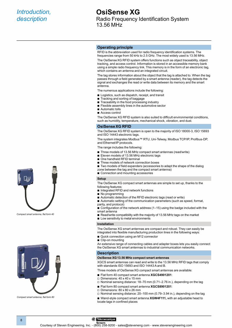
Compact smart antenna, flat form 40
Compact smart antenna, flat form 80
Operating principleRFID is the abbreviation used for radio frequency identification systems. The frequencies range from 50 kHz to 2.5 GHz. The most widely used is 13.56 MHz.The OsiSense XG RFID system offers functions such as object traceability, object tracking, and access control. Information is stored in an accessible memory bank using a simple radio frequency link. This memory is in the form of an electronic tag, which contains an antenna and an integrated circuit. The tag stores information about the object that the tag is attached to. When the tag passes through a field generated by a smart antenna (reader), the tag detects the signal and exchanges the read or write data between its memory and the smart antenna. The numerous applications include the following: b Logistics, such as dispatch, receipt, and transitb Tracking and sorting of baggageb Traceability in the food processing industryb Flexible assembly lines in the automotive sectorb Automatic tolls b Access controlThe OsiSense XG RFID system is also suited to difficult environmental conditions, such as humidity, temperature, mechanical shock, vibration, and dust.
OsiSense XG RFID The OsiSense XG RFID system is open to the majority of ISO 18000-3, ISO 15693 and ISO 14443 electronic tags.The system integrates Modbus™ RTU, Uni-Telway, Modbus TCP/IP, Profibus-DP, and Ethernet/IP protocols.The range includes the following:b Three models of 13.56 MHz compact smart antennas (read/write)b Eleven models of 13.56 MHz electronic tagsb One handheld RFID terminalb Three models of network connection boxesb Two models of field expanders (accessories to adapt the shape of the dialog zone between the tag and the compact smart antenna)b Connection and mounting accessories
SetupThe OsiSense XG compact smart antennas are simple to set up, thanks to the following features: b Integrated RFID and network functionsb No programming b Automatic detection of the RFID electronic tags (read or write)b Automatic setting of the communication parameters (such as speed, format, parity, and protocol) b Configuration of the network address (1–15) using the badge included with the smart antennab Read/write compatibility with the majority of 13.56 MHz tags on the marketb Low sensitivity to metal environments
InstallationThe OsiSense XG smart antennas are compact and robust. They can easily be integrated into flexible manufacturing production lines in the following ways:b Quick connection using an M12 connectorb Clip-on mountingAn extensive range of connecting cables and adapter boxes lets you easily connect the OsiSense XG smart antennas to industrial communication networks.
DescriptionOsiSense XG 13.56 MHz compact smart antennasXGCS smart antennas can read and write to the 13.56 MHz RFID tags that comply with standards ISO 15693 and ISO 14443 A and B.Three models of OsiSense XG compact smart antennas are available:b Flat form 40 compact smart antenna XGCS4901201: v Dimensions: 40 x 40 x 15 mmv Nominal sensing distance: 18–70 mm (0.71–2.76 in.), depending on the tagb Flat form 80 compact smart antenna XGCS8901201: v Dimensions: 80 x 80 x 26 mmv Nominal sensing distance: 20–100 mm (0.79–3.94 in.), depending on the tagb Wand-style compact smart antenna XGW4F111, with an adjustable head to locate tags in confined places
Courtesy of Steven Engineering, Inc. - (800) 258-9200 - [email protected] - www.stevenengineering.com
2
1
3
4
5
6
7
8
9
10
2
1
3
4
5
6
7
8
9
10
99
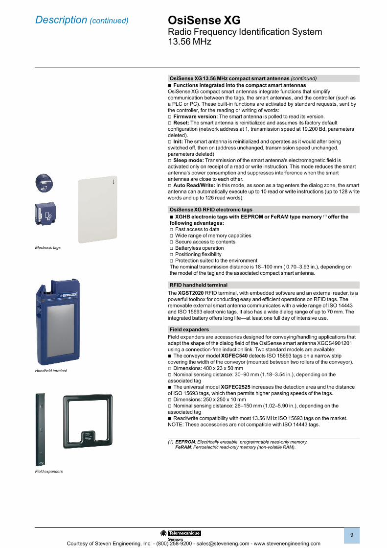
OsiSense XG 13.56 MHz compact smart antennas (continued)b Functions integrated into the compact smart antennasOsiSense XG compact smart antennas integrate functions that simplify communication between the tags, the smart antennas, and the controller (such as a PLC or PC). These built-in functions are activated by standard requests, sent by the controller, for the reading or writing of words:v Firmware version: The smart antenna is polled to read its version.v Reset: The smart antenna is reinitialized and assumes its factory default configuration (network address at 1, transmission speed at 19,200 Bd, parameters deleted).v Init: The smart antenna is reinitialized and operates as it would after being switched off, then on (address unchanged, transmission speed unchanged, parameters deleted)v Sleep mode: Transmission of the smart antenna's electromagnetic field is activated only on receipt of a read or write instruction. This mode reduces the smart antenna's power consumption and suppresses interference when the smart antennas are close to each other.v Auto Read/Write: In this mode, as soon as a tag enters the dialog zone, the smart antenna can automatically execute up to 10 read or write instructions (up to 128 write words and up to 126 read words).
OsiSense XG RFID electronic tagsb XGHB electronic tags with EEPROM or FeRAM type memory (1) offer the following advantages:v Fast access to datav Wide range of memory capacitiesv Secure access to contentsv Batteryless operationv Positioning flexibilityv Protection suited to the environmentThe nominal transmission distance is 18–100 mm ( 0.70–3.93 in.), depending on the model of the tag and the associated compact smart antenna.
RFID handheld terminal The XGST2020 RFID terminal, with embedded software and an external reader, is a powerful toolbox for conducting easy and efficient operations on RFID tags. The removable external smart antenna communicates with a wide range of ISO 14443 and ISO 15693 electronic tags. It also has a wide dialog range of up to 70 mm. The integrated battery offers long life—at least one full day of intensive use.
Field expanders Field expanders are accessories designed for conveying/handling applications that adapt the shape of the dialog field of the OsiSense smart antenna XGCS4901201 using a connection-free induction link. Two standard models are available:b The conveyor model XGFEC540 detects ISO 15693 tags on a narrow strip covering the width of the conveyor (mounted between two rollers of the conveyor).v Dimensions: 400 x 23 x 50 mmv Nominal sensing distance: 30–90 mm (1.18–3.54 in.), depending on the associated tagb The universal model XGFEC2525 increases the detection area and the distance of ISO 15693 tags, which then permits higher passing speeds of the tags.v Dimensions: 250 x 250 x 10 mmv Nominal sensing distance: 26–150 mm (1.02–5.90 in.), depending on the associated tagb Read/write compatibility with most 13.56 MHz ISO 15693 tags on the market. NOTE: These accessories are not compatible with ISO 14443 tags.
(1) EEPROM: Electrically erasable, programmable read-only memory. FeRAM: Ferroelectric read-only memory (non-volatile RAM).
Description (continued)
Electronic tags
Field expanders
OsiSense XGRadio Frequency Identification System13.56 MHz
Handheld terminal
Courtesy of Steven Engineering, Inc. - (800) 258-9200 - [email protected] - www.stevenengineering.com

2
1
3
4
5
6
7
8
9
10
2
1
3
4
5
6
7
8
9
10
1010
Description (continued) OsiSense XGRadio Frequency Identification System13.56 MHz
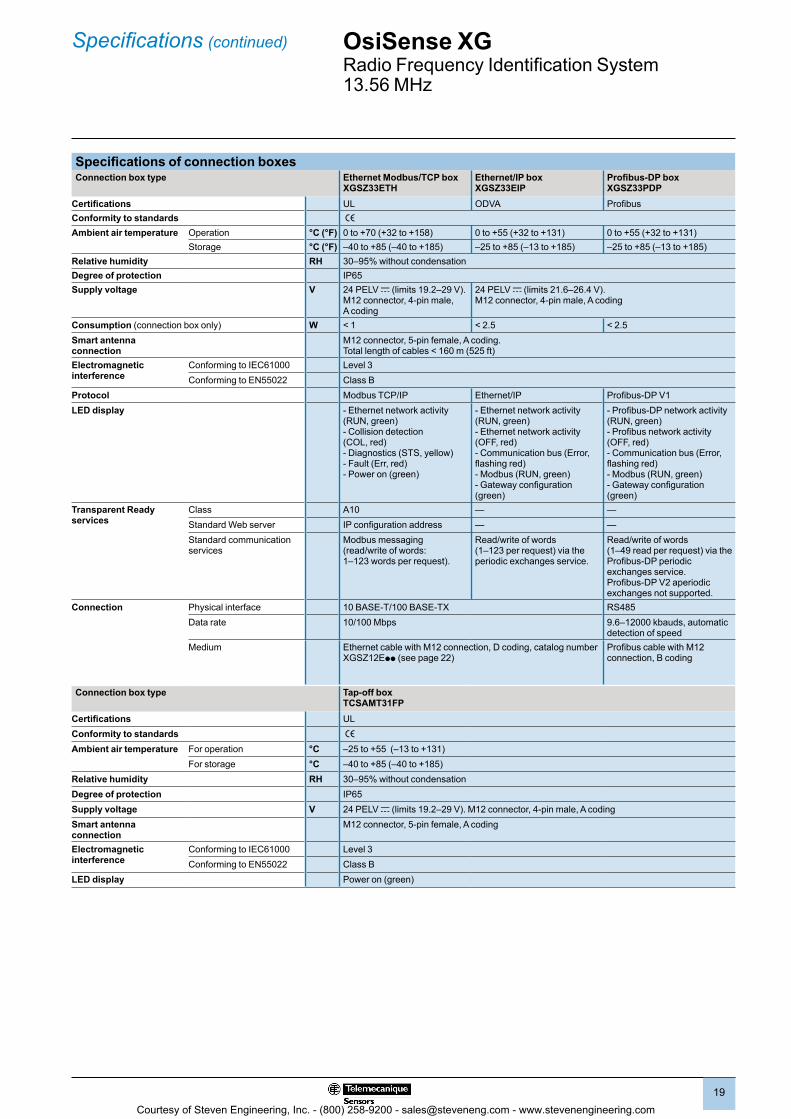
Description (continued)OsiSense XG connection boxes
Four types of quick connection boxes are available:b Ethernet box XGSZ33ETH for an Ethernet Modbus TCP/IP networkb Ethernet/IP box XGSZ33EIP for an Ethernet/IP networkb Profibus-DP box XGSZ33PDP for a Profibus-DP networkb Tap-off box TCSAMT31FP for a Modbus or Uni-Telway communication bus
Ethernet box XGSZ33ETHThe OsiSense Ethernet box XGSZ33ETH connects XGCS smart antennas to an Ethernet network (Modbus TCP/IP protocol). It provides PLC or PC access to the functions of the XGCS smart antennas: b Reading and writing of tagsb Control and commandb Monitoringb DiagnosticsThe XGSZ33ETH Ethernet box is fitted with M12 connectors for the power supply, the Ethernet network, and 1–3 XGCS smart antennas (up to 8 smart antennas by daisy-chaining).
Ethernet/IP box XGSZ33EIPThe OsiSense Ethernet/IP box XGSZ33EIP connects XGCS smart antennas to the Ethernet/IP network.
It allows a PLC or PC to access the functions of the XGCS smart antennas:b Reading and writing of tagsb Control and commandb Monitoringb DiagnosticsThe XGSZ33EIP box is fitted with M12 connectors for the power supply, the Ethernet/IP network, and 1–3 XGCS smart antennas (up to 15 smart antennas by daisy-chaining).
Profibus-DP box XGSZ33PDPThe OsiSense XG Profibus-DP box XGSZ33PDP connects XGCS smart antennas to a Profibus-DP network.
It provides PLC or PC access to the functions of the XGCS smart antennas:b Reading and writing of tagsb Control and commandb Monitoringb DiagnosticsThe XGSZ33PDP box is fitted with M12 connectors for the power supply, the Profibus-DP network, and 1–3 XGCS smart antennas (up to 15 smart antennas by daisy-chaining).
Tap-off box TCSAMT31FP The OsiSense XG tap-off box TCSAMT31FP connects XGCS smart antennas to a Modbus or Uni-Telway communication bus.
The TCSAMT31FP box is fitted with M12 connectors for the power supply, the Modbus communication bus, and 1–3 XGCS smart antennas (up to 15 smart antennas by daisy-chaining).It includes a dust- and damp-proof metal enclosure.
5
7
46 3 8 9Profibus-DP box: XGSZ33PDP
Ethernet box XGSZ33ETH
1
2
4 3
5
42 3 8 9Ethernet/IP box XGSZ33EIP
1 Power on and Ethernet signaling LEDs2 1 Ethernet socket, M12 type, D coding3 1 power supply socket, M12 type, 4-pin male4 3 sockets, M12 type, female, A coding, for
connecting XGCS smart antennas5 Configuration of the network address6 1 network input socket, M12 type, male7 1 network output socket, M12 type, female8 1 configuration port, M12 type, female9 Network and connection box status LEDs10 One green LED: Power on
Connection box TCSAMT31FP
7
3
6
4
10
IN OUT
Courtesy of Steven Engineering, Inc. - (800) 258-9200 - [email protected] - www.stevenengineering.com
2
1
3
4
5
6
7
8
9
10
2
1
3
4
5
6
7
8
9
10
1111
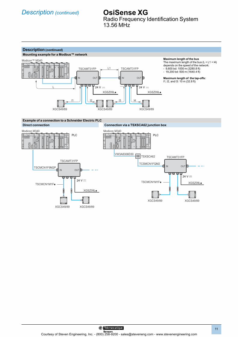
Description (continued)Mounting example for a Modbus™ network
l2l1
L
L1
24 V
l4l3
24 V
Modicon™ M340
TSCAMT31FP TSCAMT31FP
XGCS49/89XGCS49/89 XGCS49/89
IN OUT IN OUT
Maximum length of the busThe maximum length of the bus (L + L1 + l4) depends on the speed of the network:- 9,600 bd: 1000 m (3280.8 ft)- 19,200 bd: 500 m (1640.4 ft)
Maximum length of the tap-offs:l1, l2, and l3: 10 m (32.8 ft)
Example of a connection to a Schneider Electric PLCDirect connection Connection via a TSXSCA62 junction box
24 V c
TSCAMT31FP
XGSZ09Lp
TSCMCN1F9M2P
TSCMCN1M1Fp
XGCS49/89XGCS49/89
IN OUT
Modicon M340
24 V c
TSCAMT31FP
XGSZ09LpTSCMCN1M1Fp
XGCS49/89XGCS49/89
TCSMCN1FQM2
TSXSCA62VW3A8306D30
IN OUT
Modicon M340
Description (continued) OsiSense XGRadio Frequency Identification System13.56 MHz
PLC PLC
Courtesy of Steven Engineering, Inc. - (800) 258-9200 - [email protected] - www.stevenengineering.com

2
1
3
4
5
6
7
8
9
10
2
1
3
4
5
6
7
8
9
10
1212
Example of a connection on an Ethernet networkPremium
M340
XGSZ33ETHXGSZ33EIP
XGSZ33ETH
XGSZ09Lp
XGSZ09Lp
XGCS49/89
ABL8
ABL8
TCSMCN1M1F
XGSZ12Eppp
XGSZ12Eppp
TCSCTN011M11F
XGCS49/89
The number of smart antennas connected to each box can be increased by using M12 T-connectors (catalog number TCSCTN011M11F).Note when using box XGSZ33ETH on Modbus/TCP: To maintain high-performance operation, connect a maximum of eight compact smart antennas. (The Ethernet box has eight communication ports that can be open simultaneously on TCP/IP.) In cases where the I/O scanning function is used (which requires an additional communication port), do not connect more than seven smart antennas. The total length of the side network for smart antennas XGCS49 and XGCS89 is limited to 160 m (525 ft).
Example of a mixed IP20 and IP67 connection on an Ethernet network
TCSESU051F0TCSEAAF11F13F00
TCSECL1M3M pS2
c 24 V c 24 V c 24 V XGSZ09L p
XGSZ33ETH
XGSZ33EIP
XGSZ33ETH
XGSZ33EIP
XGSZ33ETH TCSMCN1M1Fp
XGCS49/89
XGCS49/89
XGCS49/89
ABL8
IP67 IP20
ConneXium switch
PLC
or or
Example of a connection to a Magelis™ terminal
c 24 V
TCSMCN1F2
XBTN / XBTG / XBTGTXGCS49/89pp
(2)(1)
Cable TCSMCN1F2 connectionsDiagram Contact Signal Wire color
21
35
4
1 Drain (Modbus-SHLD)
–
2 24 Vc Red3 0 V/Modbus-GND Black4 D0 White
5 D1 Blue
(1) SUB-D 25-pin male connector. (2) Power supply connector included with the Magelis terminal.
Description (continued) OsiSense XGRadio Frequency Identification System13.56 MHz
Ethernet switch
or
Courtesy of Steven Engineering, Inc. - (800) 258-9200 - [email protected] - www.stevenengineering.com
2
1
3
4
5
6
7
8
9
10
2
1
3
4
5
6
7
8
9
10
1313
Description (continued) OsiSense XGRadio Frequency Identification System13.56 MHz
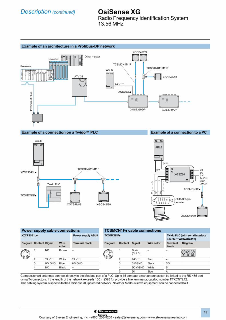
Example of an architecture in a Profibus-DP network
Quantum
ATV 31
Premium
XGCS49/89
ABL8
TCSMCN1M1FTCSCTN011M11F
XGCS49/89
XGSZ09Lp
XGSZ33PDP XGSZ33PDP
Example of a connection on a Twido™ PLC Example of a connection to a PC
XZCP1541Lp
ABL8
Twido PLC
TCSCTN011M11F
TCSMCN1Fp
XGCS49/89 XGCS49/89
XGSZ24
5 2 3TCSMCN1Fp
D1
Drain (SHLD)
D0
24 V c0 V
XGCS49/89
0 V
5 4 3 2
9 8 7 6
1
24 V c
ABL8
SUB-D 9-pin female
Power supply cable connections TCSMCN1Fp cable connectionsXZCP1541Lp Power supply ABL8 TCSMCN1Fp Twido PLC (with serial interface
adapter TWDNAC485T)Diagram Contact Signal Wire
colorTerminal block Diagram Contact Signal Wire color Terminal
blockDiagram
21
34
1 NC Brown – 21
35
4
1 Drain (SHLD)
– –
A B SG
2 24 V c White 24 V c 2 24 V c Red –3 0 V GND Blue 0 V GND 3 0 V GND Black SG4 NC Black – 4 D0 V GND White B
5 D1 Blue ACompact smart antennas connect directly to the Modbus port of a PLC. Up to 15 compact smart antennas can be linked to the RS-485 port using T-connectors. If the length of the network exceeds 100 m (328 ft), provide a line terminator, catalog number FTXCNTL12.This cabling system is specific to the OsiSense XG powered network. No other Modbus slave equipment can be connected to it.
Other master
Pro
fibus
-DP
bus
Courtesy of Steven Engineering, Inc. - (800) 258-9200 - [email protected] - www.stevenengineering.com
2
1
3
4
5
6
7
8
9
10
2
1
3
4
5
6
7
8
9
10
1414
Functions OsiSense XGRadio Frequency Identification System13.56 MHz Handheld terminal
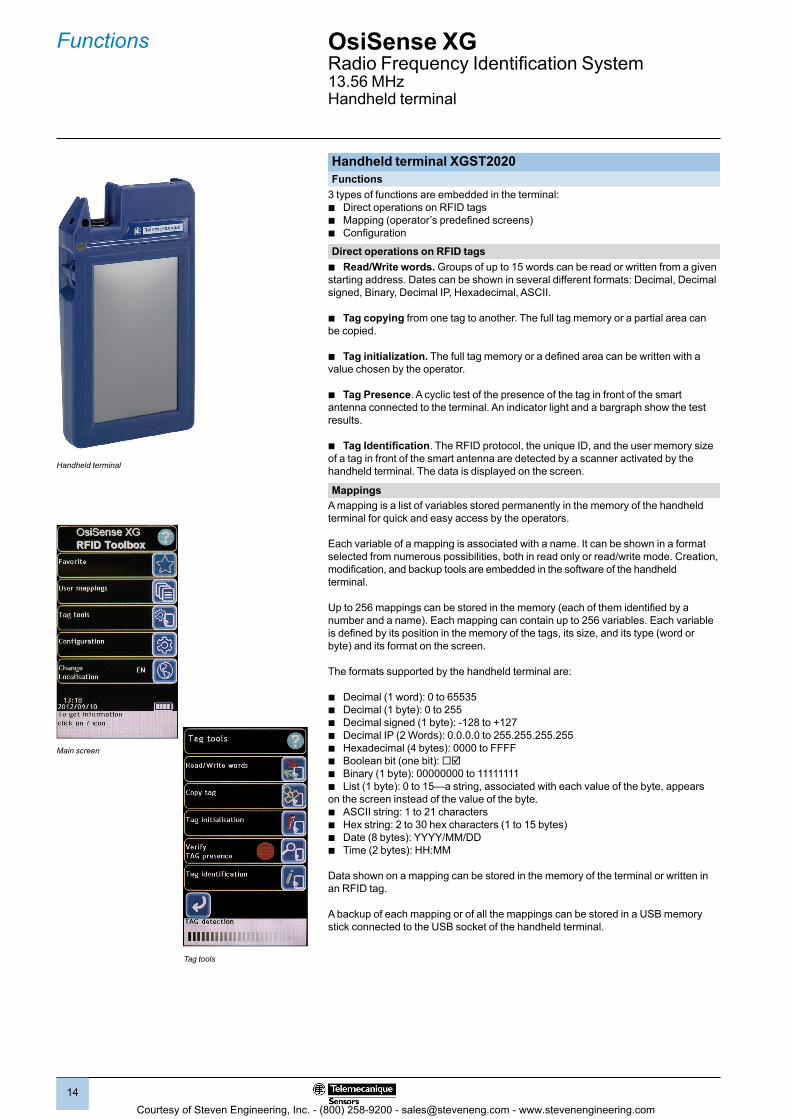
Handheld terminal XGST2020Functions
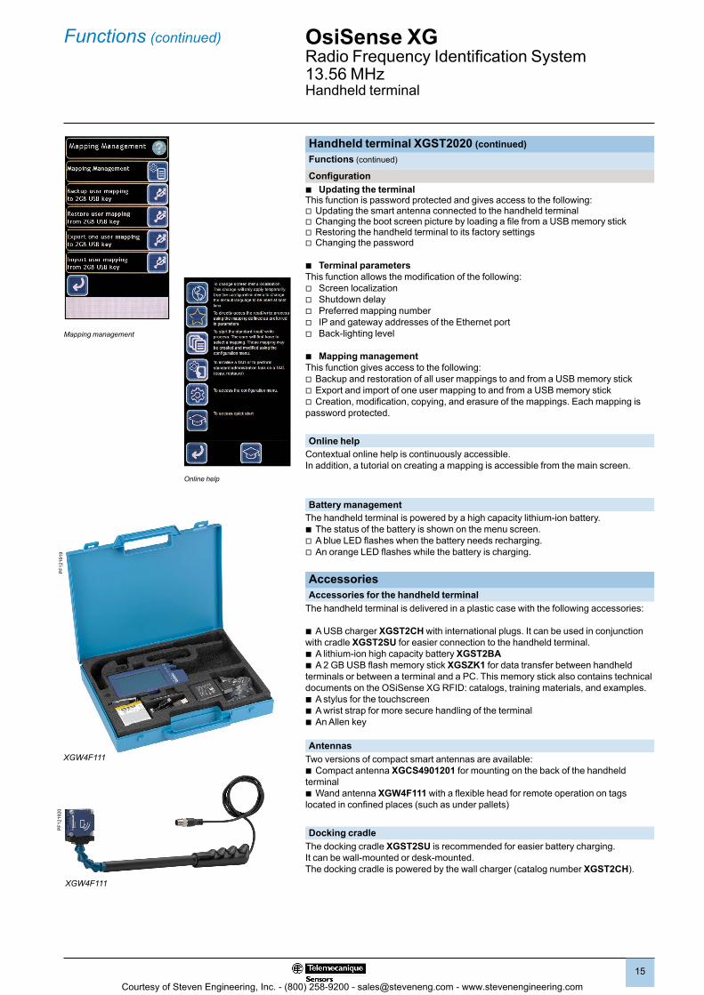
3 types of functions are embedded in the terminal: b Direct operations on RFID tags b Mapping (operator’s predefined screens) b Configuration
Direct operations on RFID tags b Read/Write words. Groups of up to 15 words can be read or written from a given
starting address. Dates can be shown in several different formats: Decimal, Decimal signed, Binary, Decimal IP, Hexadecimal, ASCII.
b Tag copying from one tag to another. The full tag memory or a partial area can be copied.
b Tag initialization. The full tag memory or a defined area can be written with a value chosen by the operator.
b Tag Presence. A cyclic test of the presence of the tag in front of the smart antenna connected to the terminal. An indicator light and a bargraph show the test results.
b Tag Identification. The RFID protocol, the unique ID, and the user memory size of a tag in front of the smart antenna are detected by a scanner activated by the handheld terminal. The data is displayed on the screen.
MappingsA mapping is a list of variables stored permanently in the memory of the handheld terminal for quick and easy access by the operators.
Each variable of a mapping is associated with a name. It can be shown in a format selected from numerous possibilities, both in read only or read/write mode. Creation, modification, and backup tools are embedded in the software of the handheld terminal.
Up to 256 mappings can be stored in the memory (each of them identified by a number and a name). Each mapping can contain up to 256 variables. Each variable is defined by its position in the memory of the tags, its size, and its type (word or byte) and its format on the screen.
The formats supported by the handheld terminal are:
b Decimal (1 word): 0 to 65535 b Decimal (1 byte): 0 to 255 b Decimal signed (1 byte): -128 to +127 b Decimal IP (2 Words): 0.0.0.0 to 255.255.255.255 b Hexadecimal (4 bytes): 0000 to FFFF b Boolean bit (one bit): b Binary (1 byte): 00000000 to 11111111 b List (1 byte): 0 to 15—a string, associated with each value of the byte, appears
on the screen instead of the value of the byte. b ASCII string: 1 to 21 characters b Hex string: 2 to 30 hex characters (1 to 15 bytes) b Date (8 bytes): YYYY/MM/DD b Time (2 bytes): HH:MM
Data shown on a mapping can be stored in the memory of the terminal or written in an RFID tag.
A backup of each mapping or of all the mappings can be stored in a USB memory stick connected to the USB socket of the handheld terminal.
Handheld terminal
Main screen
Tag tools
Courtesy of Steven Engineering, Inc. - (800) 258-9200 - [email protected] - www.stevenengineering.com
2
1
3
4
5
6
7
8
9
10
2
1
3
4
5
6
7
8
9
10
1515
Functions (continued) OsiSense XGRadio Frequency Identification System13.56 MHz Handheld terminal
Handheld terminal XGST2020 (continued)Functions (continued)
Configuration b Updating the terminal
This function is password protected and gives access to the following:v Updating the smart antenna connected to the handheld terminalv Changing the boot screen picture by loading a file from a USB memory stickv Restoring the handheld terminal to its factory settingsv Changing the password
b Terminal parameters This function allows the modification of the following:
v Screen localization v Shutdown delay v Preferred mapping number v IP and gateway addresses of the Ethernet port v Back-lighting level
b Mapping management This function gives access to the following:v Backup and restoration of all user mappings to and from a USB memory stickv Export and import of one user mapping to and from a USB memory stickv Creation, modification, copying, and erasure of the mappings. Each mapping is password protected.
Online helpContextual online help is continuously accessible. In addition, a tutorial on creating a mapping is accessible from the main screen.
Battery managementThe handheld terminal is powered by a high capacity lithium-ion battery.b The status of the battery is shown on the menu screen.v A blue LED flashes when the battery needs recharging.v An orange LED flashes while the battery is charging.
AccessoriesAccessories for the handheld terminal
The handheld terminal is delivered in a plastic case with the following accessories:
b A USB charger XGST2CH with international plugs. It can be used in conjunction with cradle XGST2SU for easier connection to the handheld terminal.b A lithium-ion high capacity battery XGST2BAb A 2 GB USB flash memory stick XGSZK1 for data transfer between handheld terminals or between a terminal and a PC. This memory stick also contains technical documents on the OSiSense XG RFID: catalogs, training materials, and examples.b A stylus for the touchscreenb A wrist strap for more secure handling of the terminalb An Allen key
AntennasTwo versions of compact smart antennas are available: b Compact antenna XGCS4901201 for mounting on the back of the handheld terminalb Wand antenna XGW4F111 with a flexible head for remote operation on tags located in confined places (such as under pallets)
Docking cradle The docking cradle XGST2SU is recommended for easier battery charging. It can be wall-mounted or desk-mounted. The docking cradle is powered by the wall charger (catalog number XGST2CH).
XGW4F111
PF1
2192
0
XGW4F111
PF1
2191
9
Online help
Mapping management
Courtesy of Steven Engineering, Inc. - (800) 258-9200 - [email protected] - www.stevenengineering.com
2
1
3
4
5
6
7
8
9
10
2
1
3
4
5
6
7
8
9
10
1616
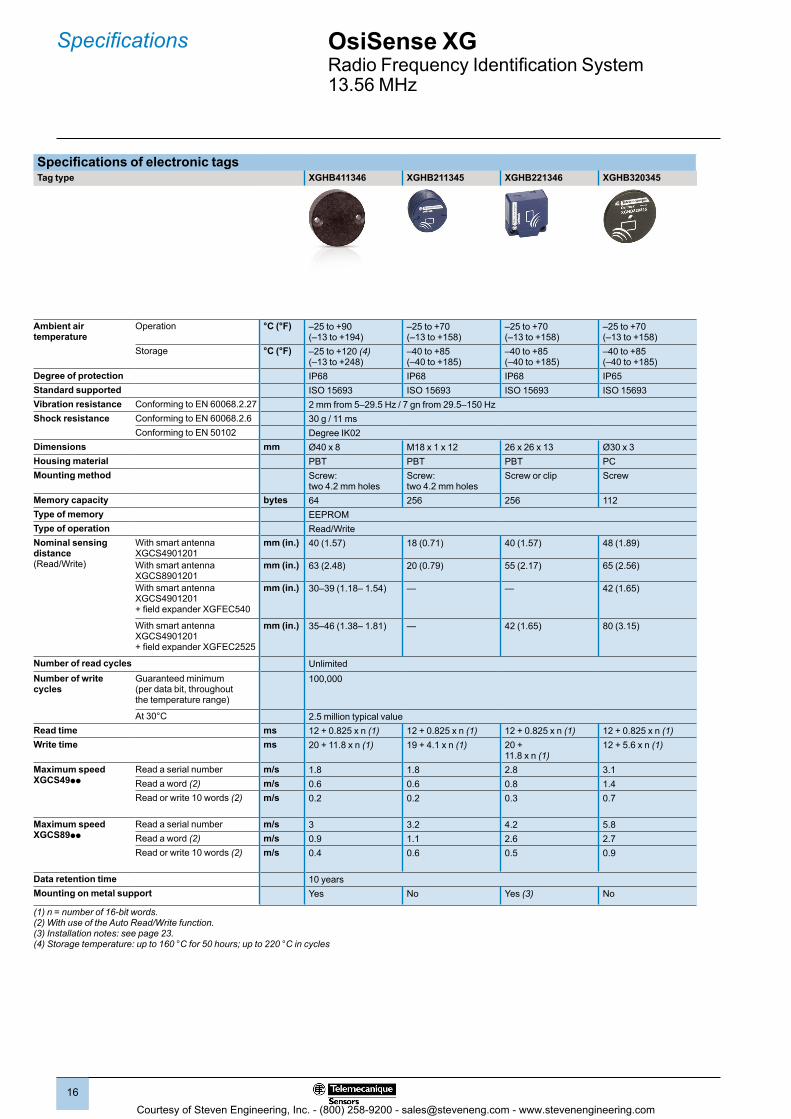
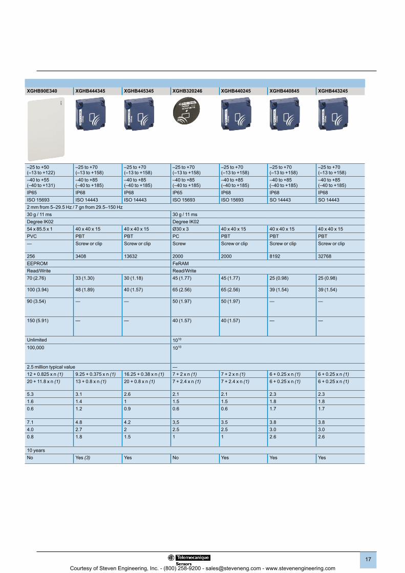
Specifications of electronic tagsTag type XGHB411346 XGHB211345 XGHB221346 XGHB320345 XGHB90E340 XGHB444345 XGHB445345 XGHB320246 XGHB440245 XGHB440845 XGHB443245
Ambient air temperature
Operation °C (°F) –25 to +90 (–13 to +194)
–25 to +70 (–13 to +158)
–25 to +70 (–13 to +158)
–25 to +70 (–13 to +158)
–25 to +50 (–13 to +122)
–25 to +70 (–13 to +158)
–25 to +70 (–13 to +158)
–25 to +70 (–13 to +158)
–25 to +70 (–13 to +158)
–25 to +70 (–13 to +158)
–25 to +70 (–13 to +158)
Storage °C (°F) –25 to +120 (4) (–13 to +248)
–40 to +85 (–40 to +185)
–40 to +85 (–40 to +185)
–40 to +85 (–40 to +185)
–40 to +55 (–40 to +131)
–40 to +85 (–40 to +185)
–40 to +85 (–40 to +185)
–40 to +85 (–40 to +185)
–40 to +85 (–40 to +185)
–40 to +85 (–40 to +185)
–40 to +85 (–40 to +185)
Degree of protection IP68 IP68 IP68 IP65 IP65 IP68 IP68 IP65 IP68 IP68 IP68Standard supported ISO 15693 ISO 15693 ISO 15693 ISO 15693 ISO 15693 ISO 14443 ISO 14443 ISO 15693 ISO 15693 SO 14443 SO 14443Vibration resistance Conforming to EN 60068.2.27 2 mm from 5–29.5 Hz / 7 gn from 29.5–150 Hz 2 mm from 5–29.5 Hz / 7 gn from 29.5–150 HzShock resistance Conforming to EN 60068.2.6 30 g / 11 ms 30 g / 11 ms 30 g / 11 ms
Conforming to EN 50102 Degree IK02 Degree IK02 Degree IK02Dimensions mm Ø40 x 8 M18 x 1 x 12 26 x 26 x 13 Ø30 x 3 54 x 85.5 x 1 40 x 40 x 15 40 x 40 x 15 Ø30 x 3 40 x 40 x 15 40 x 40 x 15 40 x 40 x 15Housing material PBT PBT PBT PC PVC PBT PBT PC PBT PBT PBTMounting method Screw:
two 4.2 mm holesScrew: two 4.2 mm holes
Screw or clip Screw — Screw or clip Screw or clip Screw Screw or clip Screw or clip Screw or clip
Memory capacity bytes 64 256 256 112 256 3408 13632 2000 2000 8192 32768Type of memory EEPROM EEPROM FeRAMType of operation Read/Write Read/Write Read/WriteNominal sensing distance (Read/Write)
With smart antenna XGCS4901201
mm (in.) 40 (1.57) 18 (0.71) 40 (1.57) 48 (1.89) 70 (2.76) 33 (1.30) 30 (1.18) 45 (1.77) 45 (1.77) 25 (0.98) 25 (0.98)
With smart antenna XGCS8901201
mm (in.) 63 (2.48) 20 (0.79) 55 (2.17) 65 (2.56) 100 (3.94) 48 (1.89) 40 (1.57) 65 (2.56) 65 (2.56) 39 (1.54) 39 (1.54)
With smart antenna XGCS4901201 + field expander XGFEC540
mm (in.) 30–39 (1.18– 1.54) — — 42 (1.65) 90 (3.54) — — 50 (1.97) 50 (1.97) — —
With smart antenna XGCS4901201 + field expander XGFEC2525
mm (in.) 35–46 (1.38– 1.81) — 42 (1.65) 80 (3.15) 150 (5.91) — — 40 (1.57) 40 (1.57) — —
Number of read cycles Unlimited Unlimited 1010
Number of write cycles
Guaranteed minimum(per data bit, throughout the temperature range)
100,000 100,000 1010
At 30°C 2.5 million typical value 2.5 million typical value —Read time ms 12 + 0.825 x n (1) 12 + 0.825 x n (1) 12 + 0.825 x n (1) 12 + 0.825 x n (1) 12 + 0.825 x n (1) 9.25 + 0.375 x n (1) 16.25 + 0.38 x n (1) 7 + 2 x n (1) 7 + 2 x n (1) 6 + 0.25 x n (1) 6 + 0.25 x n (1)Write time ms 20 + 11.8 x n (1) 19 + 4.1 x n (1) 20 +
11.8 x n (1)12 + 5.6 x n (1) 20 + 11.8 x n (1) 13 + 0.8 x n (1) 20 + 0.8 x n (1) 7 + 2.4 x n (1) 7 + 2.4 x n (1) 6 + 0.25 x n (1) 6 + 0.25 x n (1)
Maximum speed XGCS49pp
Read a serial number m/s 1.8 1.8 2.8 3.1 5.3 3.1 2.6 2.1 2.1 2.3 2.3Read a word (2) m/s 0.6 0.6 0.8 1.4 1.6 1.4 1 1.5 1.5 1.8 1.8Read or write 10 words (2) m/s 0.2 0.2 0.3 0.7 0.6 1.2 0.9 0.6 0.6 1.7 1.7
Maximum speed XGCS89pp
Read a serial number m/s 3 3.2 4.2 5.8 7.1 4.8 4.2 3,5 3.5 3.8 3.8Read a word (2) m/s 0.9 1.1 2.6 2.7 4.0 2.7 2 2.5 2.5 3.0 3.0Read or write 10 words (2) m/s 0.4 0.6 0.5 0.9 0.8 1.8 1.5 1 1 2.6 2.6
Data retention time 10 years 10 yearsMounting on metal support Yes No Yes (3) No No Yes (3) Yes No Yes Yes Yes
(1) n = number of 16-bit words.(2) With use of the Auto Read/Write function.(3) Installation notes: see page 23.(4) Storage temperature: up to 160 °C for 50 hours; up to 220 °C in cycles
OsiSense XGRadio Frequency Identification System13.56 MHz
Specifications
Courtesy of Steven Engineering, Inc. - (800) 258-9200 - [email protected] - www.stevenengineering.com
2
1
3
4
5
6
7
8
9
10
2
1
3
4
5
6
7
8
9
10
1717
Specifications of electronic tagsTag type XGHB411346 XGHB211345 XGHB221346 XGHB320345 XGHB90E340 XGHB444345 XGHB445345 XGHB320246 XGHB440245 XGHB440845 XGHB443245
Ambient air temperature
Operation °C (°F) –25 to +90 (–13 to +194)
–25 to +70 (–13 to +158)
–25 to +70 (–13 to +158)
–25 to +70 (–13 to +158)
–25 to +50 (–13 to +122)
–25 to +70 (–13 to +158)
–25 to +70 (–13 to +158)
–25 to +70 (–13 to +158)
–25 to +70 (–13 to +158)
–25 to +70 (–13 to +158)
–25 to +70 (–13 to +158)
Storage °C (°F) –25 to +120 (4) (–13 to +248)
–40 to +85 (–40 to +185)
–40 to +85 (–40 to +185)
–40 to +85 (–40 to +185)
–40 to +55 (–40 to +131)
–40 to +85 (–40 to +185)
–40 to +85 (–40 to +185)
–40 to +85 (–40 to +185)
–40 to +85 (–40 to +185)
–40 to +85 (–40 to +185)
–40 to +85 (–40 to +185)
Degree of protection IP68 IP68 IP68 IP65 IP65 IP68 IP68 IP65 IP68 IP68 IP68Standard supported ISO 15693 ISO 15693 ISO 15693 ISO 15693 ISO 15693 ISO 14443 ISO 14443 ISO 15693 ISO 15693 SO 14443 SO 14443Vibration resistance Conforming to EN 60068.2.27 2 mm from 5–29.5 Hz / 7 gn from 29.5–150 Hz 2 mm from 5–29.5 Hz / 7 gn from 29.5–150 HzShock resistance Conforming to EN 60068.2.6 30 g / 11 ms 30 g / 11 ms 30 g / 11 ms
Conforming to EN 50102 Degree IK02 Degree IK02 Degree IK02Dimensions mm Ø40 x 8 M18 x 1 x 12 26 x 26 x 13 Ø30 x 3 54 x 85.5 x 1 40 x 40 x 15 40 x 40 x 15 Ø30 x 3 40 x 40 x 15 40 x 40 x 15 40 x 40 x 15Housing material PBT PBT PBT PC PVC PBT PBT PC PBT PBT PBTMounting method Screw:
two 4.2 mm holesScrew: two 4.2 mm holes
Screw or clip Screw — Screw or clip Screw or clip Screw Screw or clip Screw or clip Screw or clip
Memory capacity bytes 64 256 256 112 256 3408 13632 2000 2000 8192 32768Type of memory EEPROM EEPROM FeRAMType of operation Read/Write Read/Write Read/WriteNominal sensing distance (Read/Write)
With smart antenna XGCS4901201
mm (in.) 40 (1.57) 18 (0.71) 40 (1.57) 48 (1.89) 70 (2.76) 33 (1.30) 30 (1.18) 45 (1.77) 45 (1.77) 25 (0.98) 25 (0.98)
With smart antenna XGCS8901201
mm (in.) 63 (2.48) 20 (0.79) 55 (2.17) 65 (2.56) 100 (3.94) 48 (1.89) 40 (1.57) 65 (2.56) 65 (2.56) 39 (1.54) 39 (1.54)
With smart antenna XGCS4901201 + field expander XGFEC540
mm (in.) 30–39 (1.18– 1.54) — — 42 (1.65) 90 (3.54) — — 50 (1.97) 50 (1.97) — —
With smart antenna XGCS4901201 + field expander XGFEC2525
mm (in.) 35–46 (1.38– 1.81) — 42 (1.65) 80 (3.15) 150 (5.91) — — 40 (1.57) 40 (1.57) — —
Number of read cycles Unlimited Unlimited 1010
Number of write cycles
Guaranteed minimum(per data bit, throughout the temperature range)
100,000 100,000 1010
At 30°C 2.5 million typical value 2.5 million typical value —Read time ms 12 + 0.825 x n (1) 12 + 0.825 x n (1) 12 + 0.825 x n (1) 12 + 0.825 x n (1) 12 + 0.825 x n (1) 9.25 + 0.375 x n (1) 16.25 + 0.38 x n (1) 7 + 2 x n (1) 7 + 2 x n (1) 6 + 0.25 x n (1) 6 + 0.25 x n (1)Write time ms 20 + 11.8 x n (1) 19 + 4.1 x n (1) 20 +
11.8 x n (1)12 + 5.6 x n (1) 20 + 11.8 x n (1) 13 + 0.8 x n (1) 20 + 0.8 x n (1) 7 + 2.4 x n (1) 7 + 2.4 x n (1) 6 + 0.25 x n (1) 6 + 0.25 x n (1)
Maximum speed XGCS49pp
Read a serial number m/s 1.8 1.8 2.8 3.1 5.3 3.1 2.6 2.1 2.1 2.3 2.3Read a word (2) m/s 0.6 0.6 0.8 1.4 1.6 1.4 1 1.5 1.5 1.8 1.8Read or write 10 words (2) m/s 0.2 0.2 0.3 0.7 0.6 1.2 0.9 0.6 0.6 1.7 1.7
Maximum speed XGCS89pp
Read a serial number m/s 3 3.2 4.2 5.8 7.1 4.8 4.2 3,5 3.5 3.8 3.8Read a word (2) m/s 0.9 1.1 2.6 2.7 4.0 2.7 2 2.5 2.5 3.0 3.0Read or write 10 words (2) m/s 0.4 0.6 0.5 0.9 0.8 1.8 1.5 1 1 2.6 2.6
Data retention time 10 years 10 yearsMounting on metal support Yes No Yes (3) No No Yes (3) Yes No Yes Yes Yes
(1) n = number of 16-bit words.(2) With use of the Auto Read/Write function.(3) Installation notes: see page 23.(4) Storage temperature: up to 160 °C for 50 hours; up to 220 °C in cycles
Courtesy of Steven Engineering, Inc. - (800) 258-9200 - [email protected] - www.stevenengineering.com

2
1
3
4
5
6
7
8
9
10
2
1
3
4
5
6
7
8
9
10
1818
Specifications
Specifications of OsiSense XG compact smart antennasSmart antenna type XGCS8901201 XGCS4901201 XGW4F111
Certifications UL, FCC part 15c, eConformity to standards EN 301489-1, EN 301489-3, ETS 300330-1 and ETS 300330-2Ambient air temperature For operation °C –25 to +70 (–13 to 158°F)
For storage °C –40 to +85 (–40 to 158°F)Degree of protection Conforming to IEC 60529 IP65Vibration resistance Conforming to EN 60068.2.27 2 mm from 5–29.5 Hz / 7 gn from 29.5–150 HzShock resistance Conforming to EN 60068.2.6 30 g / 11 ms
Conforming to EN 50102 Degree IK02Resistance to interference Conforming to IEC 61000 Resistance to electrostatic discharge, radiated electromagnetic fields, fast transients,
electrical surges, conducted and induced interference, and network frequency magnetic fields.
Dimensions, W x H x D mm Flat form: 80 x 80 x 26 Flat form: 40 x 40 x 15 290 x 40 x 25RFID frequency MHz 13.56Nominal sensing distance Depending on the associated tag
mm (in.)
20–100 (0.79–3.94), 10–70 (0.39–2.76)
Type of associated tag ISO 15693 and ISO 14443 standard tags. Automatic detection of the tag type.Compatible RFID microchip examples Fujitsu (MB89R118), INSIDE (micropass)
NXP (I-Code SL2, SL1, Ultralight, Std 1K/4K, Desfire), STM (CRIX4K)Texas (Tag-it HFI), µEM4135
Nominal supply voltage Vdc 24 PELV c (protective extra-low voltage)Supply voltage limits (including ripple) Vdc 19.2–29 cConsumption mA < 60Serial link Type RS-485
Protocol Modbus RTU or Uni-Telway Modbus RTUSpeed Bauds 9,600–115,000 (automatic detection)
Display 1 dual color LED for the communication network: Modbus / Uni-Telway1 dual color LED for RFID communication: presence of tag / smart antenna / tag dialog
Connections A single, shielded M12 connector, 5-pin male, A coding, for connection to the communication network and power supply.
Tightening torque Screws N•m < 3 < 1 —
Specifications of handheld terminal XGST2020Certifications eConformity to standards IEC 61000-6-2, IEC61000-6-4Ambient air temperature For operation °C 0 to +45 (+32 to +113°F)
For storage °C –20 to +45 (–4 to +113°F)Materials Housing ABSPower supply Internal Battery, lithium-ion 3.7 V / 4,000 mAh. Full charge duration: 8 hours
Connector for charging Mini USBAutonomy Typical > 8 hours (reading a tag each minute, brightness of the screen = standard)
Minimum > 3 hours (continuous reading)Charging time Maximum < 8 hours (to fully charge a completely flat battery)Degree of protection Conforming to IEC 60529 IP40
Conforming to IEC 62262 IK02 (touchscreen)Drop test Free fall on concrete ground: 1 m (39.37 in.)
Connection to RFID reader serial link
Connector M12 female socketType RS485Protocol Modbus RTU - MasterSpeed Bauds 115,000
External port USB for memory stick (2 GB maximum)Operating system Proprietary operating systemDisplay Resistive OLED touchscreen: 480 x 272 pixels, 16 M colorsSignaling Dual color (blue/orange) power status LED
Specifications of accessoriesType of accessory XGST2CH charger set XGST2SU docking cradle
for handheld terminal XGST2020Certifications e —Input voltage 100–240 V c, 50/60 Hz, 0.3 A maximum 5 V c, 1 A maximumOutputs 5 V c, 1 A maximum x 2 outputs 5 V c, 0.5 A maximumConnections Input Interchangeable international plugs Connected to charger XGST2CH
Output Mini USB cable, length 1 m (3.28 ft) Spring contacts
OsiSense XGRadio Frequency Identification System13.56 MHz
Courtesy of Steven Engineering, Inc. - (800) 258-9200 - [email protected] - www.stevenengineering.com
2
1
3
4
5
6
7
8
9
10
2
1
3
4
5
6
7
8
9
10
1919
Specifications (continued)
Specifications of connection boxesConnection box type Ethernet Modbus/TCP box
XGSZ33ETHEthernet/IP box XGSZ33EIP
Profibus-DP box XGSZ33PDP
Certifications UL ODVA ProfibusConformity to standards eAmbient air temperature Operation °C (°F) 0 to +70 (+32 to +158) 0 to +55 (+32 to +131) 0 to +55 (+32 to +131)
Storage °C (°F) –40 to +85 (–40 to +185) –25 to +85 (–13 to +185) –25 to +85 (–13 to +185)Relative humidity RH 30–95% without condensationDegree of protection IP65Supply voltage V 24 PELV c (limits 19.2–29 V).
M12 connector, 4-pin male, A coding
24 PELV c (limits 21.6–26.4 V). M12 connector, 4-pin male, A coding
Consumption (connection box only) W < 1 < 2.5 < 2.5Smart antenna connection
M12 connector, 5-pin female, A coding. Total length of cables < 160 m (525 ft)
Electromagnetic interference
Conforming to IEC61000 Level 3Conforming to EN55022 Class B
Protocol Modbus TCP/IP Ethernet/IP Profibus-DP V1LED display - Ethernet network activity
(RUN, green)- Collision detection (COL, red)- Diagnostics (STS, yellow)- Fault (Err, red)- Power on (green)
- Ethernet network activity (RUN, green)- Ethernet network activity (OFF, red)- Communication bus (Error, flashing red)- Modbus (RUN, green)- Gateway configuration (green)
- Profibus-DP network activity (RUN, green)- Profibus network activity (OFF, red)- Communication bus (Error, flashing red)- Modbus (RUN, green)- Gateway configuration (green)
Transparent Ready services
Class A10 — —Standard Web server IP configuration address — —Standard communication services
Modbus messaging(read/write of words: 1–123 words per request).
Read/write of words (1–123 per request) via the periodic exchanges service.
Read/write of words (1–49 read per request) via the Profibus-DP periodic exchanges service. Profibus-DP V2 aperiodic exchanges not supported.
Connection Physical interface 10 BASE-T/100 BASE-TX RS485Data rate 10/100 Mbps 9.6–12000 kbauds, automatic
detection of speedMedium Ethernet cable with M12 connection, D coding, catalog number
XGSZ12Epp (see page 22)Profibus cable with M12 connection, B coding
Connection box type Tap-off box TCSAMT31FP
Certifications ULConformity to standards eAmbient air temperature For operation °C –25 to +55 (–13 to +131)
For storage °C –40 to +85 (–40 to +185)Relative humidity RH 30–95% without condensationDegree of protection IP65Supply voltage V 24 PELV c (limits 19.2–29 V). M12 connector, 4-pin male, A codingSmart antenna connection
M12 connector, 5-pin female, A coding
Electromagnetic interference
Conforming to IEC61000 Level 3 Conforming to EN55022 Class B
LED display Power on (green)
OsiSense XGRadio Frequency Identification System13.56 MHz
Courtesy of Steven Engineering, Inc. - (800) 258-9200 - [email protected] - www.stevenengineering.com
2
1
3
4
5
6
7
8
9
10
2
1
3
4
5
6
7
8
9
10
2020
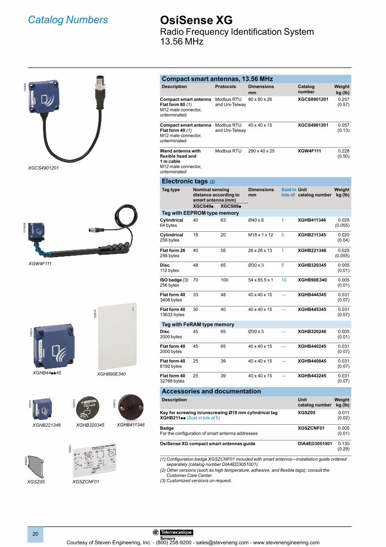
Compact smart antennas, 13.56 MHzDescription Protocols Dimensions
mmCatalog number
Weightkg (lb)
Compact smart antennaFlat form 80 (1) M12 male connector, unterminated
Modbus RTU and Uni-Telway
80 x 80 x 26 XGCS8901201 0.257(0.57)
Compact smart antennaFlat form 40 (1) M12 male connector, unterminated
Modbus RTU and Uni-Telway
40 x 40 x 15 XGCS4901201 0.057 (0.13)
Wand antenna with flexible head and 1 m cable M12 male connector, unterminated
Modbus RTU 290 x 40 x 25 XGW4F111 0.228 (0.50)
Electronic tags (2)
Tag type Nominal sensing distance according to smart antenna (mm)
Dimensions mm
Sold in lots of
Unit catalog number
Weightkg (lb)
XGCS49p XGCS89p
Tag with EEPROM type memoryCylindrical 64 bytes
40 63 Ø40 x 8 1 XGHB411346 0.025(0.055)
Cylindrical256 bytes
18 20 M18 x 1 x 12 5 XGHB211345 0.020 (0.04)
Flat form 26256 bytes
40 55 26 x 26 x 13 1 XGHB221346 0.025(0.055)
Disc112 bytes
48 65 Ø30 x 3 5 XGHB320345 0.005 (0.01)
ISO badge (3) 256 bytes
70 100 54 x 85.5 x 1 10 XGHB90E340 0.005 (0.01)
Flat form 40 3408 bytes
33 48 40 x 40 x 15 — XGHB444345 0.031 (0.07)
Flat form 4013632 bytes
30 40 40 x 40 x 15 — XGHB445345 0.031 (0.07)
Tag with FeRAM type memoryDisc2000 bytes
45 65 Ø30 x 3 — XGHB320246 0.005 (0.01)
Flat form 402000 bytes
45 65 40 x 40 x 15 — XGHB440245 0.031 (0.07)
Flat form 408192 bytes
25 39 40 x 40 x 15 — XGHB440845 0.031 (0.07)
Flat form 4032768 bytes
25 39 40 x 40 x 15 — XGHB443245 0.031 (0.07)
Accessories and documentationDescription Unit
catalog numberWeightkg (lb)
Key for screwing in/unscrewing Ø18 mm cylindrical tagXGHB211pp (Sold in lots of 5)
XGSZ05 0.011 (0.02)
Badge For the configuration of smart antenna addresses
XGSZCNF01 0.005 (0.01)
OsiSense XG compact smart antennas guide DIA4ED3051001 0.130 (0.29)
(1) Configuration badge XGSZCNF01 included with smart antenna—installation guide ordered separately (catalog number DIA4ED3051001).
(2) Other versions (such as high temperature, adhesive, and flexible tags): consult the Customer Care Center.
(3) Customized versions on request.
Catalog Numbers10
5909
XGHB44pp45
1059
10
XGHB221346
1059
11
1059
12
XGHB411346XGHB320345
1059
13
1059
14
XGHB90E340
OsiSense XGRadio Frequency Identification System13.56 MHz
8066
03
XGSZ05
1059
21
XGSZCNF01
XGW4F111
1219
20A
XGCS4901201
Courtesy of Steven Engineering, Inc. - (800) 258-9200 - [email protected] - www.stevenengineering.com

2
1
3
4
5
6
7
8
9
10
2
1
3
4
5
6
7
8
9
10
2121
Connection boxesDescription For use with Supply
voltageCatalog number Weight
kg (lb)Ethernet Modbus/ TCP box
Compact smart antennasXGCS49p and XGCS89p
24 V c XGSZ33ETH 1.060 (2.34)
Ethernet/IP box (1) Compact smart antennasXGCS49p and XGCS89p
24 V c XGSZ33EIP 1.060 (2.34)
Profibus-DP box (1) Compact smart antennasXGCS49p and XGCS89p
24 V c XGSZ33PDP 1.060 (2.34)
Tap-off box, 3-channel Modbus and Uni-Telway
Compact smart antennasXGCS49p and XGCS89p
24 V c TCSAMT31FP 1.060 (2.34)
Field expandersDescription Nominal
sensing distanceFor use with Catalog number Weight
kg (lb)Conveying type field expanderDimensions (mm) 400 x 23 x 50 (2)
30–90 mm depending on tag used (only ISO 15693)
Smart antenna XGCS4901201Tags XGHB90E340 XGHB320345XGHB221346
XGFEC540 0.640 (1.41)
Universal type field expanderDimensions (mm) 250 x 250 x 10 (2)
26–150 mm depending on tag used (only ISO 15693)
Smart antenna XGCS4901201Tags XGHB90E340 XGHB320345
XGFEC2525 0.565 (1.25)
OsiSense XG handheld terminalDescription Composition Catalog number Weight
kg (lb)Handheld terminal RFID set in a plastic case (3)
b 1 handheld terminal b 1 wrist strap b 1 lithium-ion battery b 1 charger battery pack b 1 stylus b 1 USB memory stick
XGST2422 1.000 (2.20)
Note: RFID antenna ordered separately (see page 14).
AccessoriesDescription Catalog number Weight
kg (lb)Screen protection sheetsSold in lots of 5
XGST2FP 0.005 (0.01)
StylusesSold in lots of 3
XGST2ST 0.006 (0.01)
Docking cradle XGST2SU 0.086 (0.19)
Spare partsHandheld terminalTerminal unit only (without battery, charger, or RFID reader)
XGST2020 0.295 (0.65)
Lithium-ion battery3.7 V, 4000 mAh
XGST2BA 0.078 (0.17)
International charger pack XGST2CH 0.160 (0.35)
USB memory stick2 GB
XGSZK1 0.008 (0.02)
(1) Configuration file and installation guide to be downloaded from www.tesensors.com.(2) For other dimensions consult the Customer Care Center.(3) RFID reader ordered separately.
Catalog Numbers (continued)
TCSAMT31FP
1059
15
XGFEC540
5398
28
XGFEC2525
5398
29
OsiSense XGRadio Frequency Identification System13.56 MHz
XGST2422
PF1
2191
9P
F121
917
XGST2BA
PF1
2191
8
XGST2CH
Courtesy of Steven Engineering, Inc. - (800) 258-9200 - [email protected] - www.stevenengineering.com

2
1
3
4
5
6
7
8
9
10
2
1
3
4
5
6
7
8
9
10
2222
OsiSense XGRadio Frequency Identification System13.56 MHz
Catalog Numbers (continued)10
6410
ABL8MEM24003
Modbus network connection accessoriesDescription Application Length
mCatalog number Weight
kg (lb)Modbus shielded connection cable, black, IP67M12 connectors, male/female, A coding (1)
RS-485 connection between a compact smart antenna and a tap-off box or between 2 tap-off boxes, TCSAMT31FP
1 TCSMCN1M1F1 0.080 (0.18)2 TCSMCN1M1F2 0.115 (0.25)5 TCSMCN1M1F5 0.270 (0.60)10 TCSMCN1M1F10 0.520 (1.15)
Modbus shielded pre-wired M12 connector, IP67, female/bare wires,A coding (1)
Connection between tap-off box TCSAMT31FP and a Modbus/Uni-Telway network (TSXSCA50 T-junction box)
2 TCSMCN1F2 0.115 (0.25)5 TCSMCN1F5 0.270 (0.60)10 TCSMCN1F10 0.520 (1.15)
Modbus shielded connecting cable, black, M12/SUBD-15, A coding
Connection between tap-off box TCSAMT31FP and a Modbus/Uni-Telway network (TSXSCA62 Y-junction box)
2 TCSMCN1FQM2 0.270 (0.60)
Modbus shielded connecting cable, black, M12/Mini-DIN 8-pin, A coding
Modbus connection between tap-off box TCSAMT31FP and a PLC (such as the Twido range)
2 TCSMCN1F9M2P 0.350 (0.77)
Modbus SL serial link Shielded dual twisted pair RS-485 main cables
Modbus SL Serial link 100 TSXCSA100 5.680 (12.52)
200 TSXCSA200 10.920 (24.07)
500 TSXCSA500 30.000 (66.14)
Network Tee, M12 1M/2F 5-pin, A coding
RS485 network — TCSCTN011M11F 0.035 (0.08)
Ethernet connection accessories Ethernet connection accessories for IP67 switchDescription End fittings Length
mCatalog number Weight
kg (lb)Copper connecting cables, straight
1 x IP67 M12 4-pin connector and 1 x RJ45 connector
1 XGSZ12E4501 —3 XGSZ12E4503 —10 XGSZ12E4510 —
2 x IP67 M12 4-pin connectors
1 XGSZ12E1201 —3 XGSZ12E1203 —10 XGSZ12E1210 —25 XGSZ12E1225 —
Copper connecting cables, elbowed
1 x IP67 M12 4-pin elbowed connector and 1 x RJ45 connector
3 XGSZ22E4503 —10 XGSZ22E4510 —
M12 Ethernet switchIP67, ConneXium (2)
— — TCSESU051F0 0.210 (0.46)
M12 female/RJ45 adapter
Ethernet connection — TCSEAAF11F13F00 —
Do-It-Yourself copper Ethernet cable and connectorsWith the Do-It-Yourself ConneXium range, you can construct copper Ethernet connecting cables of the required length on-site. These cables are for connecting to the Ethernet 110/100 Mbps network. The maximum length of these connecting cables is 80 m. They are quick to assemble using only a knife and ordinary wire cutters—no special tool is required.Description Specifications Length
(m)Catalog number Weight
kg (lb)Copper Ethernet cable 2 x 24 AWG shielded twisted pairs
Conforms to current standards and approvals
300 TCSECN300R2 —
RJ45 connector Conforms to EIA/TIA-568-D
— TCSEK3MDS —
M12 connector Conforms to IEC 60176-2-101
— TCSEK1MDRS —
Power supplies (Schneider Electric)Description Output
voltageNominal power
Nominal current
Catalog number
Weight
V c W A kg (lb)Regulated power supply 100/240 V
24 7 0.3 ABL8MEM24003 0.180 (0.40)30 1.2 ABL8MEM24012 0.520 (1.15)
(1) Holder for the identification legend included with the product.(2) Other ConneXium connection accessories: refer to www.schneider-electric.com.
TCSMCN1FQM2
1059
25
TCSMCN1F9M2P
1059
27
TCSESU051F0
5358
03
TCSEAAF11F13F00
5356
25
TCSCTN011M11F
1069
27
Courtesy of Steven Engineering, Inc. - (800) 258-9200 - [email protected] - www.stevenengineering.com
2
1
3
4
5
6
7
8
9
10
2
1
3
4
5
6
7
8
9
10
2323
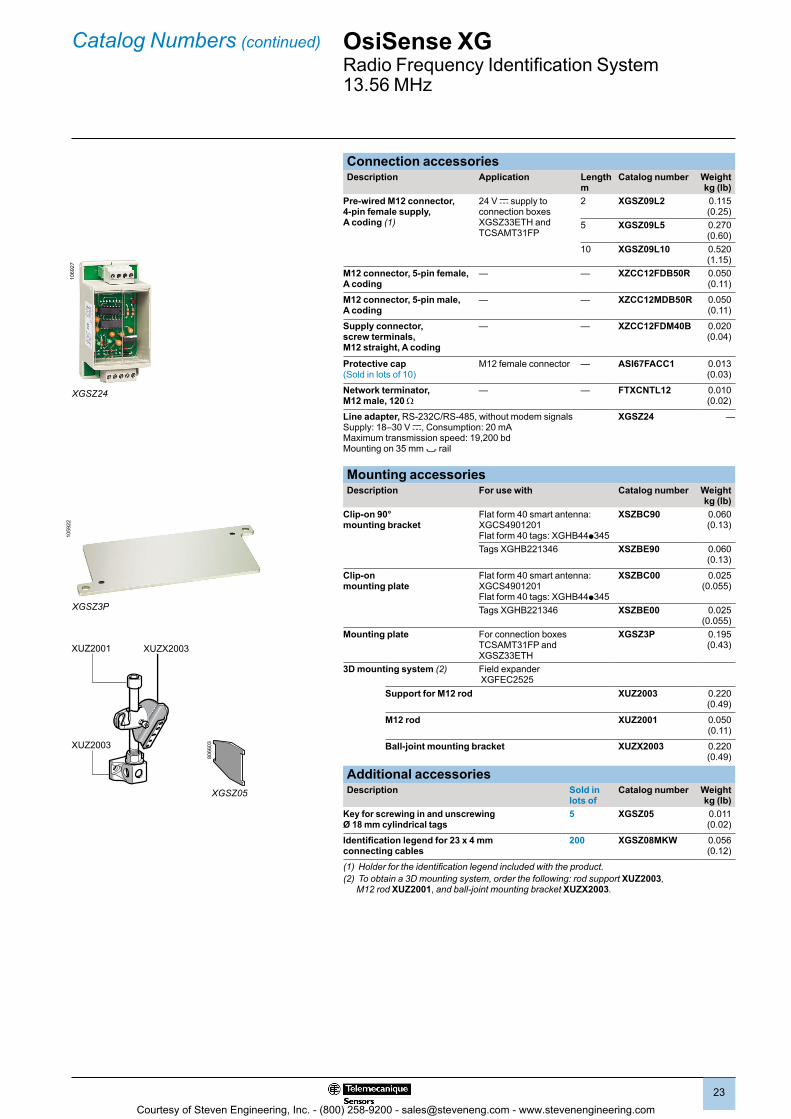
Connection accessoriesDescription Application Length
mCatalog number Weight
kg (lb)Pre-wired M12 connector, 4-pin female supply, A coding (1)
24 V c supply to connection boxes XGSZ33ETH and TCSAMT31FP
2 XGSZ09L2 0.115 (0.25)
5 XGSZ09L5 0.270 (0.60)
10 XGSZ09L10 0.520 (1.15)
M12 connector, 5-pin female, A coding
— — XZCC12FDB50R 0.050 (0.11)
M12 connector, 5-pin male, A coding
— — XZCC12MDB50R 0.050 (0.11)
Supply connector, screw terminals, M12 straight, A coding
— — XZCC12FDM40B 0.020 (0.04)
Protective cap (Sold in lots of 10)
M12 female connector — ASI67FACC1 0.013 (0.03)
Network terminator, M12 male, 120 W
— — FTXCNTL12 0.010 (0.02)
Line adapter, RS-232C/RS-485, without modem signals Supply: 18–30 V c, Consumption: 20 mA Maximum transmission speed: 19,200 bd Mounting on 35 mm 7 rail
XGSZ24 —
Mounting accessories Description For use with Catalog number Weight
kg (lb)Clip-on 90° mounting bracket
Flat form 40 smart antenna: XGCS4901201 Flat form 40 tags: XGHB44p345
XSZBC90 0.060 (0.13)
Tags XGHB221346 XSZBE90 0.060 (0.13)
Clip-on mounting plate
Flat form 40 smart antenna: XGCS4901201 Flat form 40 tags: XGHB44p345
XSZBC00 0.025(0.055)
Tags XGHB221346 XSZBE00 0.025(0.055)
Mounting plate For connection boxes TCSAMT31FP and XGSZ33ETH
XGSZ3P 0.195 (0.43)
3D mounting system (2) Field expander XGFEC2525
Support for M12 rod XUZ2003 0.220 (0.49)
M12 rod XUZ2001 0.050 (0.11)
Ball-joint mounting bracket XUZX2003 0.220 (0.49)
Additional accessoriesDescription Sold in
lots ofCatalog number Weight
kg (lb)Key for screwing in and unscrewing Ø 18 mm cylindrical tags
5 XGSZ05 0.011 (0.02)
Identification legend for 23 x 4 mm connecting cables
200 XGSZ08MKW 0.056 (0.12)
(1) Holder for the identification legend included with the product. (2) To obtain a 3D mounting system, order the following: rod support XUZ2003,
M12 rod XUZ2001, and ball-joint mounting bracket XUZX2003.
Catalog Numbers (continued)
XUZ2003
XUZ2001 XUZX2003
XGSZ3P
1059
22
OsiSense XGRadio Frequency Identification System13.56 MHz
XGSZ24
1069
27
8066
03
XGSZ05
Courtesy of Steven Engineering, Inc. - (800) 258-9200 - [email protected] - www.stevenengineering.com

2
1
3
4
5
6
7
8
9
10
2
1
3
4
5
6
7
8
9
10
2424
Compact smart antennasXGCS4901201 XGCS8901201
9,815
4014
4033
(2)
(3)
1626
8014
80
65
(2)
4XØ5,5 (1)
(3)
(1) For CHC type screws. (2) Shielded cable (20 cm long). (3) M12 connector, 5-pin male, A coding.
Updatable code electronic tagsSquare format tags Rectangular format tagsXGHB44pp XGHB221346 XGHB90E340
26
2613
8,8 33 4XØ3,5 (1) 54
1 85,5
(1) For CHC type screws.Cylindrical format tagsXGHB32pp XGHB411346 XGHB123345
Ø30
3Ø3
11 M40x11 8 Ø12
Connection boxes (1)Connection box TCSAMT31FP Box XGSZ33ETH (Ethernet)
Boxes XGSZ33PDP (Profibus-DP) and XGSZ33EIP (Ethernet/IP) Mounting plate XGSZ3P
60
100
66=
=
158145= =
4 x M5
(2)
(1) Allow a 110 mm clearance zone for connecting the cables.(2) This connector is only present on the Profibus-DP box.
9,8
15
40
40
4XØ4,5 (1)33
8050=
=
130
115= =51
IN OUT
51
8050=
=
130
115= =
2,5
155
115= =
7460 50=
=
2xØ5,4
2xØ4,3
140= =
Dimensions OsiSense XGRadio Frequency Identification System13.56 MHz
Courtesy of Steven Engineering, Inc. - (800) 258-9200 - [email protected] - www.stevenengineering.com

2
1
3
4
5
6
7
8
9
10
2
1
3
4
5
6
7
8
9
10
2525
Dimensions (continued)
Handheld RFID terminal Field expandersXGST2020 (30 mm deep) Conveying type XGFEC540
80
150
400
70130130
50
2415
==
4xM4
XGCS4901201
(1)
(1) 4 x M4 screws (included).Universal type XGFEC2525
220=
==
=
60
210
248
248
111577
(1) XGCS49012014xM4
(1) 4 x M4 screws (included).
Mounting brackets Mounting platesFor smart antennas XGCS49pp and tags XGHB44pp
For smart antennas XGCS49pp and tags XGHB44pp
XSZBC90 XSZBC0016 (1)
10 30 42
44,344,436,9 M5
16
12
103042
77,24,5
M5 (1)
(1) 4 screws, M4 x 14 (included). (1) 4 screws, M4 x 14 (included).
For tags XGHB221346XSZBE90 XSZBE00
10
27,46 17
23,9
29,4
30,8
M3
(1)
5,5
1011,9
617 27,4
48,5
M3
(1)
(1) 2 screws, M3 x 12 (included). (1) 2 screws, M3 x 12 (included).
OsiSense XGRadio Frequency Identification System13.56 MHz
Courtesy of Steven Engineering, Inc. - (800) 258-9200 - [email protected] - www.stevenengineering.com
2
1
3
4
5
6
7
8
9
10
2
1
3
4
5
6
7
8
9
10
2626
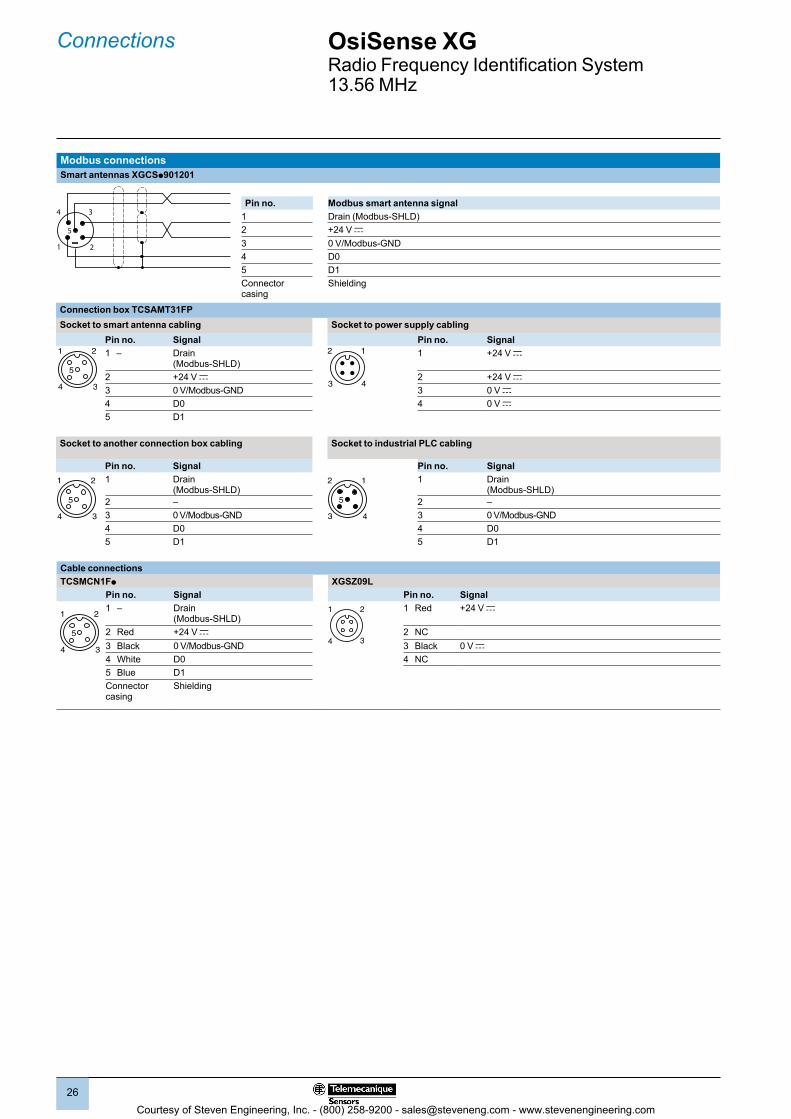
Connections
Modbus connectionsSmart antennas XGCSp901201
34
21
5
Pin no. Modbus smart antenna signal1 Drain (Modbus-SHLD)2 +24 V c3 0 V/Modbus-GND4 D05 D1Connector casing
Shielding
Connection box TCSAMT31FPSocket to smart antenna cabling Socket to power supply cabling
Pin no. Signal Pin no. Signal1 – Drain
(Modbus-SHLD)1 +24 V c
2 +24 V c 2 +24 V c3 0 V/Modbus-GND 3 0 V c4 D0 4 0 V c5 D1
Socket to another connection box cabling Socket to industrial PLC cabling
Pin no. Signal Pin no. Signal1 2
4 3
5
1 Drain (Modbus-SHLD)
5
12
43
1 Drain (Modbus-SHLD)
2 – 2 –3 0 V/Modbus-GND 3 0 V/Modbus-GND4 D0 4 D05 D1 5 D1
Cable connectionsTCSMCN1Fp XGSZ09L
Pin no. Signal Pin no. Signal
1 2
4 3
5
1 – Drain (Modbus-SHLD)
34
21 1 Red +24 V c
2 Red +24 V c 2 NC3 Black 0 V/Modbus-GND 3 Black 0 V c4 White D0 4 NC5 Blue D1Connector casing
Shielding
OsiSense XGRadio Frequency Identification System13.56 MHz
1 2
4 3
5
2
4
1
3
Courtesy of Steven Engineering, Inc. - (800) 258-9200 - [email protected] - www.stevenengineering.com
2
1
3
4
5
6
7
8
9
10
2
1
3
4
5
6
7
8
9
10
2727
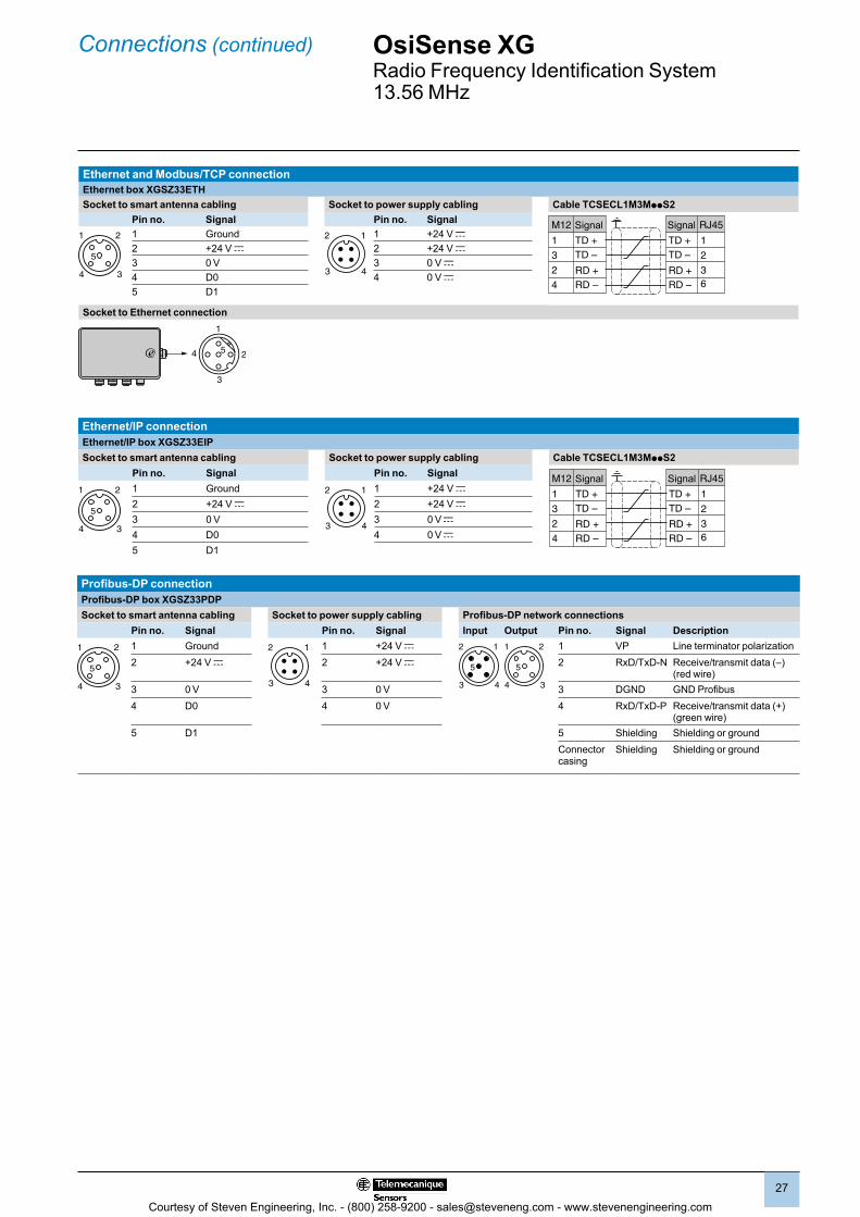
OsiSense XGRadio Frequency Identification System13.56 MHz
Connections (continued)
Ethernet and Modbus/TCP connectionEthernet box XGSZ33ETHSocket to smart antenna cabling Socket to power supply cabling Cable TCSECL1M3MppS2
Pin no. Signal Pin no. Signal M12
TD +TD –
RD +RD –
1
3
2
4
RJ45
TD +TD –
RD +RD –
1
2
36
Signal Signal1 Ground 1 +24 V c2 +24 V c 2 +24 V c3 0 V 3 0 V c4 D0 4 0 V c5 D1
Socket to Ethernet connection
3
4 2
1
5
Ethernet/IP connectionEthernet/IP box XGSZ33EIPSocket to smart antenna cabling Socket to power supply cabling Cable TCSECL1M3MppS2
Pin no. Signal Pin no. Signal M12
TD +TD –
RD +RD –
1
3
2
4
RJ45
TD +TD –
RD +RD –
1
2
36
Signal Signal1 Ground 2
4
1
3
1 +24 V c2 +24 V c 2 +24 V c3 0 V 3 0 V c4 D0 4 0 V c5 D1
Profibus-DP connectionProfibus-DP box XGSZ33PDPSocket to smart antenna cabling Socket to power supply cabling Profibus-DP network connections
Pin no. Signal Pin no. Signal Input Output Pin no. Signal Description1 Ground 2
4
1
3
1 +24 V c 2 1
3 4
5
1 2
4 3
5
1 VP Line terminator polarization2 +24 V c 2 +24 V c 2 RxD/TxD-N Receive/transmit data (–)
(red wire) 3 0 V 3 0 V 3 DGND GND Profibus4 D0 4 0 V 4 RxD/TxD-P Receive/transmit data (+)
(green wire)5 D1 5 Shielding Shielding or ground
Connector casing
Shielding Shielding or ground
1 2
4 3
5
2
4
1
3
1 2
4 3
5
1 2
4 3
5
Courtesy of Steven Engineering, Inc. - (800) 258-9200 - [email protected] - www.stevenengineering.com
2
1
3
4
5
6
7
8
9
10
2
1
3
4
5
6
7
8
9
10
2828
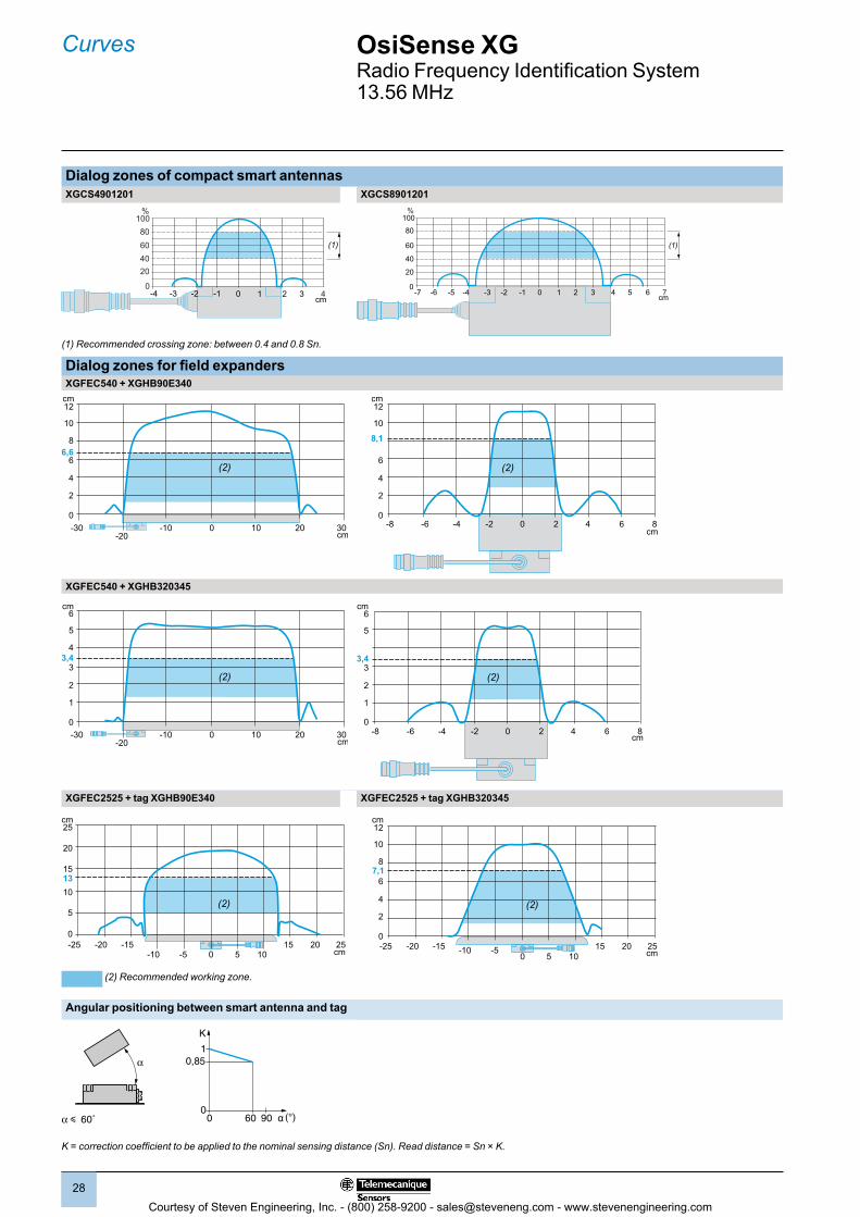
Curves OsiSense XGRadio Frequency Identification System13.56 MHz
Dialog zones of compact smart antennasXGCS4901201 XGCS8901201
(1)
01 2 3 4-4 -3 -2 -1 0
20406080
%
cm
100
7cm
00 1 2 3 4 5 6-6-7 -5 -4 -3 -2 -1
20
40
60
80
100%
(1)
(1) Recommended crossing zone: between 0.4 and 0.8 Sn.
Dialog zones for field expandersXGFEC540 + XGHB90E340
00 10 20 30-10
-20-30
2
4
66,6
8
10
12cm
cm
(2)
cm
00 2 4 6 8-2-4-6-8
2
4
6
8,1
10
12cm
(2)
XGFEC540 + XGHB320345
00 10 20 30-10
-20-30
1
2
33,4
4
5
6cm
cm
(2)
cm
00 2 4 6 8-2-4-6-8
1
2
33,4
5
6cm
(2)
XGFEC2525 + tag XGHB90E340 XGFEC2525 + tag XGHB320345
cm
0
0 5 1015 20 25
-5-10-15-20-25
5
101315
20
25cm
(2)
cm0 5 1015 20 25-5-10-15-20-25
0
2
4
67,1
8
10
12cm
(2)
(2) Recommended working zone.
Angular positioning between smart antenna and tag
α
α y 60˚ α
0,85
(°)
1
K
00 60 90
K = correction coefficient to be applied to the nominal sensing distance (Sn). Read distance = Sn × K.
Courtesy of Steven Engineering, Inc. - (800) 258-9200 - [email protected] - www.stevenengineering.com
2
1
3
4
5
6
7
8
9
10
2
1
3
4
5
6
7
8
9
10
2929
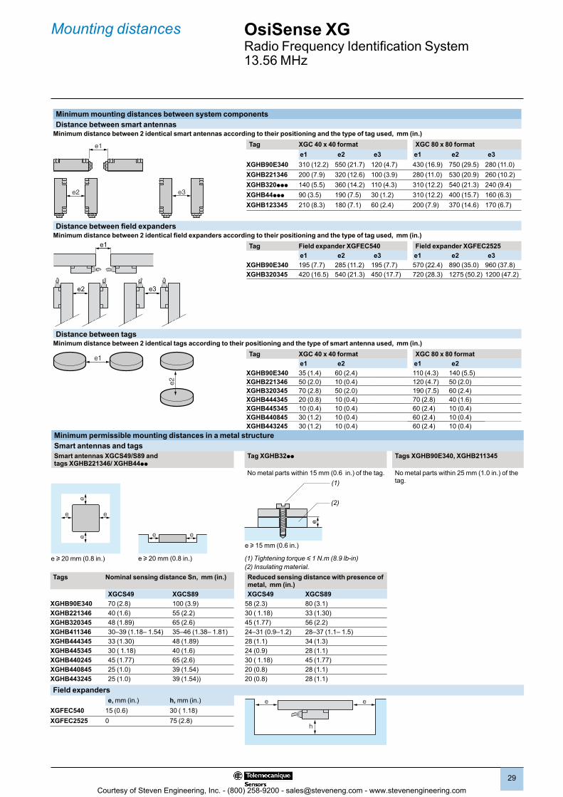
OsiSense XGRadio Frequency Identification System13.56 MHz
Minimum mounting distances between system componentsDistance between smart antennas
Minimum distance between 2 identical smart antennas according to their positioning and the type of tag used, mm (in.)Tag XGC 40 x 40 format XGC 80 x 80 format
e1 e2 e3 e1 e2 e3XGHB90E340 310 (12.2) 550 (21.7) 120 (4.7) 430 (16.9) 750 (29.5) 280 (11.0)XGHB221346 200 (7.9) 320 (12.6) 100 (3.9) 280 (11.0) 530 (20.9) 260 (10.2)XGHB320ppp 140 (5.5) 360 (14.2) 110 (4.3) 310 (12.2) 540 (21.3) 240 (9.4)XGHB44ppp 90 (3.5) 190 (7.5) 30 (1.2) 310 (12.2) 400 (15.7) 160 (6.3)XGHB123345 210 (8.3) 180 (7.1) 60 (2.4) 200 (7.9) 370 (14.6) 170 (6.7)
Distance between field expandersMinimum distance between 2 identical field expanders according to their positioning and the type of tag used, mm (in.)
e2 e3
e1 Tag Field expander XGFEC540 Field expander XGFEC2525e1 e2 e3 e1 e2 e3
XGHB90E340 195 (7.7) 285 (11.2) 195 (7.7) 570 (22.4) 890 (35.0) 960 (37.8)XGHB320345 420 (16.5) 540 (21.3) 450 (17.7) 720 (28.3) 1275 (50.2) 1200 (47.2)
Distance between tagsMinimum distance between 2 identical tags according to their positioning and the type of smart antenna used, mm (in.)
Tag XGC 40 x 40 format XGC 80 x 80 format e1 e2 e1 e2
XGHB90E340 35 (1.4) 60 (2.4) 110 (4.3) 140 (5.5)XGHB221346 50 (2.0) 10 (0.4) 120 (4.7) 50 (2.0)XGHB320345 70 (2.8) 50 (2.0) 190 (7.5) 60 (2.4)XGHB444345 20 (0.8) 10 (0.4) 70 (2.8) 40 (1.6)XGHB445345 10 (0.4) 10 (0.4) 60 (2.4) 10 (0.4)XGHB440845 30 (1.2) 10 (0.4) 60 (2.4) 10 (0.4)XGHB443245 30 (1.2) 10 (0.4) 60 (2.4) 10 (0.4)
Minimum permissible mounting distances in a metal structureSmart antennas and tagsSmart antennas XGCS49/S89 and tags XGHB221346/ XGHB44pp
Tag XGHB32pp Tags XGHB90E340, XGHB211345
No metal parts within 15 mm (0.6 in.) of the tag. No metal parts within 25 mm (1.0 in.) of the tag.
e
(1)
(2)
e u 15 mm (0.6 in.)
(1) Tightening torque y 1 N.m (8.9 lb-in)(2) Insulating material.
Tags Nominal sensing distance Sn, mm (in.) Reduced sensing distance with presence of metal, mm (in.)
XGCS49 XGCS89 XGCS49 XGCS89XGHB90E340 70 (2.8) 100 (3.9) 58 (2.3) 80 (3.1)XGHB221346 40 (1.6) 55 (2.2) 30 ( 1.18) 33 (1.30)XGHB320345 48 (1.89) 65 (2.6) 45 (1.77) 56 (2.2)XGHB411346 30–39 (1.18– 1.54) 35–46 (1.38– 1.81) 24–31 (0.9–1.2) 28–37 (1.1– 1.5)XGHB444345 33 (1.30) 48 (1.89) 28 (1.1) 34 (1.3)XGHB445345 30 ( 1.18) 40 (1.6) 24 (0.9) 28 (1.1)XGHB440245 45 (1.77) 65 (2.6) 30 ( 1.18) 45 (1.77)XGHB440845 25 (1.0) 39 (1.54) 20 (0.8) 28 (1.1)XGHB443245 25 (1.0) 39 (1.54)) 20 (0.8) 28 (1.1)
Field expanderse, mm (in.) h, mm (in.) e e
h
XGFEC540 15 (0.6) 30 ( 1.18)XGFEC2525 0 75 (2.8)
e1
e2 e3
e1
e2
Mounting distances
e e
e e
ee
e u 20 mm (0.8 in.)e u 20 mm (0.8 in.)
Courtesy of Steven Engineering, Inc. - (800) 258-9200 - [email protected] - www.stevenengineering.com
30
1.0 1.0
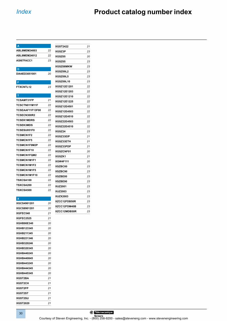
Index Product catalog number index
AABL8MEM24003 22
ABL8MEM24012 22
ASI67FACC1 23
DDIA4ED3051001 20
FFTXCNTL12 23
TTCSAMT31FP 21
TCSCTN011M11F 22
TCSEAAF11F13F00 22
TCSECN300R2 22
TCSEK1MDRS 22
TCSEK3MDS 22
TCSESU051F0 22
TCSMCN1F2 22
TCSMCN1F5 22
TCSMCN1F9M2P 22
TCSMCN1F10 22
TCSMCN1FQM2 22
TCSMCN1M1F1 22
TCSMCN1M1F2 22
TCSMCN1M1F5 22
TCSMCN1M1F10 22
TSXCSA100 22
TSXCSA200 22
TSXCSA500 22
XXGCS4901201 20
XGCS8901201 20
XGFEC540 21
XGFEC2525 21
XGHB90E340 20
XGHB123345 20
XGHB211345 20
XGHB221346 20
XGHB320246 20
XGHB320345 20
XGHB440245 20
XGHB440845 20
XGHB443245 20
XGHB444345 20
XGHB445345 20
XGST2BA 21
XGST2CH 21
XGST2FP 21
XGST2ST 21
XGST2SU 21
XGST2020 21
XGST2422 21
XGSZ3P 23
XGSZ05 20
XGSZ05 23
XGSZ08MKW 23
XGSZ09L2 23
XGSZ09L5 23
XGSZ09L10 23
XGSZ12E1201 22
XGSZ12E1203 22
XGSZ12E1210 22
XGSZ12E1225 22
XGSZ12E4501 22
XGSZ12E4503 22
XGSZ12E4510 22
XGSZ22E4503 22
XGSZ22E4510 22
XGSZ24 23
XGSZ33EIP 21
XGSZ33ETH 21
XGSZ33PDP 21
XGSZCNF01 20
XGSZK1 21
XGW4F111 20
XSZBC00 23
XSZBC90 23
XSZBE00 23
XSZBE90 23
XUZ2001 23
XUZ2003 23
XUZX2003 23
XZCC12FDB50R 23
XZCC12FDM40B 23
XZCC12MDB50R 23
Courtesy of Steven Engineering, Inc. - (800) 258-9200 - [email protected] - www.stevenengineering.com

Courtesy of Steven Engineering, Inc. - (800) 258-9200 - [email protected] - www.stevenengineering.com

Telemecanique Sensors
Schneider Electric USA, Inc.1875 Founders DriveDayton, Ohio 45420(800) 435-2121www.tesensors.us
Schneider Electric Canada, Inc.5985 McLaughlin RoadMississauga, Ontario L5R 1B8(800) 435-2121www.tesensors.ca
www.tesensors.comElectrical equipment should be installed, operated, serviced, and maintained only by qualified personnel. No responsibility is assumed by Schneider Electric for any consequences arising out of the use of this material.The information provided in this documentation contains general descriptions and/or technical characteristics of the performance of the products contained herein. This documentation is not intended as a substitute for and is not to be used for determining suitability or reliability of these products for specific user applications. It is the duty of any such user or integrator to perform the appropriate and complete risk analysis, evaluation and testing of the products with respect to the relevant specific application or use thereof. Neither Schneider Electric nor any of its affiliates or subsidiaries shall be responsible or liable for misuse of the information contained herein.© 2010–2014 Schneider Electric. All Rights Reserved. Schneider Electric, Telemecanique, OsiSense, Modicon, Modbus, Magelis, and Twido are trademarks owned by Schneider Electric Industries SAS or its affiliated companies. All other trademarks are the property of their respective owners.9006CT0902R06/13 January 2014. Replaces 9006CT0902R12/11 March 2012.
Courtesy of Steven Engineering, Inc. - (800) 258-9200 - [email protected] - www.stevenengineering.com