SCHMIDT Flow Sensor Instructions for Use
36
SCHMIDT ® Flow Sensor SS 20.500 Instructions for Use
Transcript of SCHMIDT Flow Sensor Instructions for Use

SCHMIDT® Flow Sensor
SS 20.500
Instructions for Use

Instructions for Use – SCHMIDT® Flow Sensor SS 20.500 Page 2
SCHMIDT® Flow Sensor SS 20.500
Table of Contents
1 Important information....................................................................... 3
2 Application range ............................................................................. 4
3 Mounting instructions....................................................................... 5
4 Electrical connection...................................................................... 21
5 Signalling ....................................................................................... 24
6 Commissioning .............................................................................. 28
7 Information concerning operation .................................................. 29
8 Service information ........................................................................ 31
9 Technical data ............................................................................... 34
10 Declaration of conformity ............................................................... 35
Imprint:
Copyright 2019 SCHMIDT Technology GmbH
All rights reserved
Version 523375.02F
Subject to modifications

Instructions for Use – SCHMIDT® Flow Sensor SS 20.500 Page 3
1 Important information
The instructions for use contain all required information for a fast commis-sioning and a safe operation of SCHMIDT® flow sensors.
These instructions for use must be read completely and observed carefully, before putting the unit into operation.
Working on a pressurized system as well as assembly, electrical in-stallation, commissioning and operation of the sensor may only be carried out by trained specialists. Safety and accident prevention reg-ulations must be observed.
Any claims under the manufacturer's liability for damage resulting from non-observance or non-compliance with these instructions will become void.
Tampering with the device in any way whatsoever - with the exception of the designated use and the operations described in these instruc-tions for use - will forfeit any warranty and exclude any liability.
The unit is designed exclusively for the use described below (refer to chapter 2). In particular, it is not designed for direct or indirect protec-tion of personal and machinery.
SCHMIDT Technology cannot give any warranty as to its suitability for certain purpose and cannot be held liable for accidental or sequen-tial damage in connection with the delivery, performance or use of this unit.
Symbols used in this manual
All the symbols used in this manual are explained in the following section.
Danger warnings and safety instructions - please read them!
Non-observance of these instructions may lead to personal injury or malfunction of the device.
General note
All dimensions are indicated in mm.
!

Instructions for Use – SCHMIDT® Flow Sensor SS 20.500 Page 4
2 Application range
The SCHMIDT® Flow Sensor SS 20.500 (article number 521501) is de-signed for stationary measurement of the flow velocity as well as the tem-perature of air and gas at working pressure of up to 10 bar1.
The sensor is based on the measuring principle of a thermal anemometer and measures the mass flow of the measuring medium as flow velocity, which is output in a linear way as standard velocity2 wN, based on standard conditions of 1013.25 hPa and 20 °C. Thus, the resulting output signal is independent from the pressure and temperature of the measuring me-dium.
The sensor has the following special features in connection with its unique patented sensor tip design:
o Omnidirectional measurement recording
o High sensitivity (lower measuring threshold: 0.06 m/s)
o High turn down ratio (max. measuring range: 50 m/s)
o No undercuts
o Sterilizability using hydrogen peroxide3, alcohols etc.
o High soiling tolerance
o High chemical media resistance4
These features predetermine that the sensor is used, for example in:
Clean room
Flow channel or duct
Free-space application
When using the sensor outdoors, it must be protected against direct exposure to the weather.
Mechanical versions
The sensor SS 20.500 is available in a version as compact sensor (probe is fixed at housing) and as a remote sensor (the probe is connected with its sensor housing via a cable).
The remote version is limited to atmospheric applications.
1 Only compact sensor; remote version is limited to atmospheric applications. 2 Corresponds to the actual velocity under standard conditions. 3 Use of hydrogen peroxide only with uncoated version. 4 Especially with optional coatings.
!
!

Instructions for Use – SCHMIDT® Flow Sensor SS 20.500 Page 5
3 Mounting instructions
General information on handling
The flow sensor SS 20.500 is a precision instrument with high measuring sensitivity, which can be achieved only by means of fine structure of the measuring probe (see Figure 3-1). Therefore, avoid applying mechanical force to the probe tip.
Figure 3-1
Especially when inserting or extracting the probe into/from through-chan-nels (e.g. in a through-bolt joint) even slight tilting can lead to damage of the tip.
Therefore, SCHMIDT Technology delivers the sensor with a protective cap5 placed onto the probe tip, which should be removed only during final installation in longitudinal direction. Moreover, vice versa when dismount-ing the sensor the protective cap must be attached in place immediately. When handling the sensor generally proceed with great care.
The sensor probe can be damaged irreversibly due to mechani-cal loads. Leave the protective cap during mounting as long as possible attached and handle the sensor with care.
5 Made of coloured polycarbonate
66
L
67G
1/2
9
9
40 18 16
SW32
4545
!

Instructions for Use – SCHMIDT® Flow Sensor SS 20.500 Page 6
Systems with overpressure
The compact version of the SS 20.500 is designed for a maximum working pressure of 10 bar. As long as the medium to be measured is operated with overpressure, make sure that:
There is no overpressure in the system during mounting.
Mounting and dismounting of the sensor in pipes can be car-ried out only as long as the system is in depressurized state.
Only suitable pressure-tight mounting accessories are used.
Appropriate safety devices are installed to avoid unintended discard-ing of the sensor due to overpressure.
For measurements in media with overpressure, appropriate safety measures must be taken to prevent unintended discard-ing of the sensor.
The through-bolt joints available from SCHMIDT Technology for over-pressure applications (see subchapter "Accessories") contain a pressure protection kit designed especially for this purpose. In case of other acces-sories or alternative mounting solutions the customer must ensure corre-sponding safety measures.
The components of the pressure protection kit (bolt, chain and bracket) have to be checked regularly for integrity.
Flow characteristics
Local turbulences of the medium can cause distortion of measurement results. Therefore, appropriate installation conditions must be guaranteed to ensure that the gas flow is supplied to the measuring probe in a lami-nar6, i.e. quiet and low in turbulence, state. The corresponding measures depend on the system properties (pipe, flow box, outdoor environment etc.), they are described in the following subchapters for different mount-ing variants.
Correct measurements require laminar flow with as low turbu-lence as possible.
6 The term “laminar” means here an airflow low in turbulence (not according to its physical definition saying that the Reynolds number is < 2300).
!
!
!
!
Instructions for Use – SCHMIDT® Flow Sensor SS 20.500 Page 7
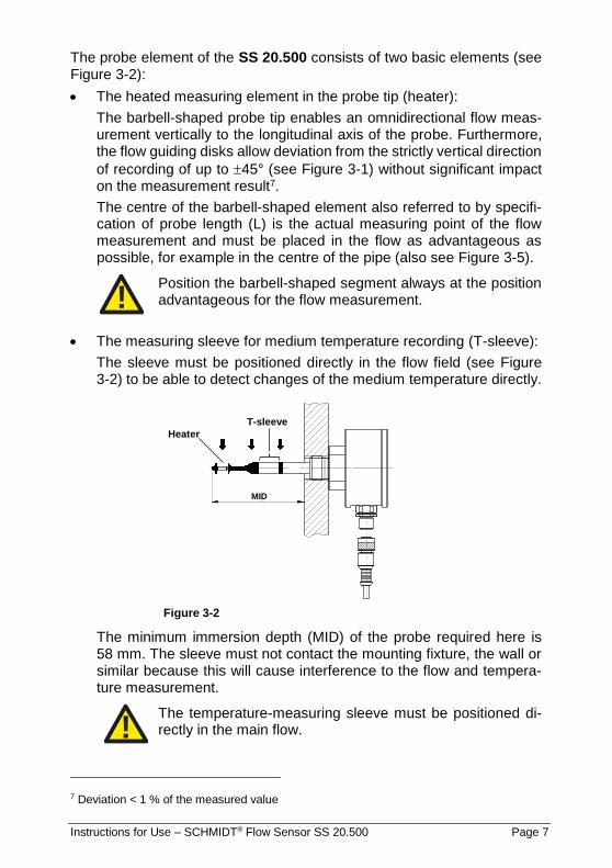
The probe element of the SS 20.500 consists of two basic elements (see Figure 3-2):
The heated measuring element in the probe tip (heater):
The barbell-shaped probe tip enables an omnidirectional flow meas-urement vertically to the longitudinal axis of the probe. Furthermore, the flow guiding disks allow deviation from the strictly vertical direction
of recording of up to 45° (see Figure 3-1) without significant impact on the measurement result7.
The centre of the barbell-shaped element also referred to by specifi-cation of probe length (L) is the actual measuring point of the flow measurement and must be placed in the flow as advantageous as possible, for example in the centre of the pipe (also see Figure 3-5).
Position the barbell-shaped segment always at the position advantageous for the flow measurement.
The measuring sleeve for medium temperature recording (T-sleeve):
The sleeve must be positioned directly in the flow field (see Figure 3-2) to be able to detect changes of the medium temperature directly.
Figure 3-2
The minimum immersion depth (MID) of the probe required here is 58 mm. The sleeve must not contact the mounting fixture, the wall or similar because this will cause interference to the flow and tempera-ture measurement.
The temperature-measuring sleeve must be positioned di-rectly in the main flow.
7 Deviation < 1 % of the measured value
!
Tmin
!
MID
Heater
T-sleeve

Instructions for Use – SCHMIDT® Flow Sensor SS 20.500 Page 8
Mounting in pipes with circular cross-section
The mounting in a flow guiding pipe is carried out by means of a through-bolt joint (for details refer to subchapter "Mounting with through-bolt joint").
The installation of the sensor must be performed at the point with laminar (low turbulence) flow profile to guarantee correct measurement results. The easiest method to achieve this is to provide a sufficiently long and straight distance without disturbances (such as edges, seams, bends etc.) in front (inlet) and behind the sensor (outlet; see installation drawing Fig-ure 3-3). It is also necessary to pay attention to the design of the outlet distance because disturbances also generate turbulences against flow di-rection.
Figure 3-3
L Length of whole measuring distance
L1 Length of inlet distance
L2 Length of outlet distance
D Inner diameter of measuring section
The absolute length of the corresponding distance is defined by the inner diameter of the pipe because the flow abatement depends directly on the aspect ratio of the measuring distance to diameter. Therefore, the required abatement distances are specified as a multiple of the pipe diameter D. Furthermore, the degree of turbulence generated by the respective inter-ference object plays a major role. A slightly curved bend directs the air with relative low disturbance level compared to a valve generating mas-sive turbulences with its abrupt change of the flow-guiding cross-section requiring a relatively long distance for abatement.
The required abatement distances (in relation to the pipe inner diameter D) for different disturbances are shown in Table 1.

Instructions for Use – SCHMIDT® Flow Sensor SS 20.500 Page 9
Flow obstacle up-stream of measur-ing section
Minimum length of in-let distance
(L1)
Minimum length of out-let distance
(L2)
Light bend (< 90°)
10 x D 5 x D
Reduction, expan-sion, 90° bend or T-junction
15 x D 5 x D
Two 90° bends in one plane (2-dimensional)
20 x D 5 x D
Two 90° bends with 3-dimensional change in direction
35 x D 5 x D
Shut-off valve
45 x D 5 x D
Table 1
This table lists the minimum values required in each case. If it is not pos-sible to observe the specified abatement distances, increased deviations of the measurement results are to be expected or it is necessary to take additional measures, for example to use flow rectifiers8.
Under laminar conditions a quasi-parabolic speed profile is formed over the pipe cross-section, whereas the flow velocity at the pipe walls remains almost zero, in the middle of the pipe it reaches the optimum measuring point, its maximum wN. This measurement value can be converted to an
average speed Nw constant over the pipe cross-section by means of a
correction factor, the so-called profile factor PF. The profile factor depends on the pipe diameter9 and is given in Table 2.
8 For example, honeycombs made of plastic or ceramics; profile factor may change. 9 Here interior air friction as well as obstruction caused by sensor is considered.

Instructions for Use – SCHMIDT® Flow Sensor SS 20.500 Page 10
Thus, it is possible to calculate the standard volumetric flow of the medium using the measured standard flow velocity in a pipe with known inner di-ameter:
𝐴 = 𝜋
4∙ 𝐷2
�̅�𝑁 = 𝑃𝐹 ∙ 𝑤𝑁
�̇�𝑁 = �̅�𝑁 ∙ 𝐴
PF
Pipe Ø Measuring range of volumetric flow [m3/h]
Inner Outer For sensor measuring range
[mm] [mm] 1 m/s 2.5 m/s 10 m/s 20 m/s 35 m/s
0.710 70.3 76.1 10 25 99 198 347
0.710 76.1 82,5 12 29 116 233 407
0.720 82.5 88.9 14 35 139 277 485
0.740 100.8 108.0 21 53 213 425 744
0.750 107.1 114.3 24 61 243 486 851
0.760 125.0 133.0 34 84 336 672 1.175
0.775 131.7 139.7 38 95 380 760 1.330
0.795 150.0 159.0 51 126 506 1,012 1,770
0.810 159.3 168.3 58 145 581 1,162 2,034
0.820 182.5 193.7 77 193 772 1,544 2,703
0.840 206.5 219.1 101 253 1,013 2,026 3,545
0.840 260.4 273.0 161 403 1,610 3,221 5,637
0.845 309.7 323.9 229 573 2,292 4,583 8,020
0.845 339.6 355.6 276 689 2,755 5,511 9,644
0.850 388.8 406.4 363 908 3,633 7,266 12,715
0.850 437.0 457.0 459 1,147 4,590 9,179 16,064
0.850 486.0 508.0 568 1,419 5,677 11,353 19,868
0.850 534.0 559.0 685 1,713 6,853 13,706 23,986
0.850 585.0 610.0 822 2,056 8,225 16,450 28,787
0.850 631.6 660.0 959 2,397 9,587 19,175 33,555
Table 2
SCHMIDT Technology provides a "flow calculator" on its homepage (page: "Service & Support") for calculation of flow velocity or volume flow in pipes for various sensor types:
http://www.schmidt-sensors.com/ or http://www.schmidttechnology.com/
D Inner diameter of pipe [m]
A Cross-section area of pipe [m2]
Nw Standard flow velocity in pipe centre [m/s]
Nw Average standard flow velocity in tube [m/s]
PF Profile factor (for pipes with circular cross-sections)
NV Standard volumetric flow [m3/s]

Instructions for Use – SCHMIDT® Flow Sensor SS 20.500 Page 11
Mounting in ducts with rectangular cross-section
In most applications it is a room or chamber with a square flow through cross-section. Based on flow conditions there is a distinguishment be-tween two cases:
Quasi-uniform flow field
The lateral dimensions of the flow guiding system are approximately as large as its length in flow direction and flow velocity is relatively small so that a laminar trapezoidal10 speed profile of the flow is formed. The width of the flow gradient zone at the wall is negligible relatively to chamber width so that a constant flow velocity can be assumed over the whole chamber cross-section. The sensor must be mounted here in such a way that its sensor tip is far enough from the wall and it measures in the area with constant flow field.
Typical applications are:
o Flow box
o Clean room
Quasi-parabolic flow profile
The system length is large compared to the cross-section surface and flow velocity is so high that the ratios correspond to that of a circular pipe. This means that the same requirements apply here to installa-tion conditions.
Since the situation is similar to that in a pipe11, the volumetric flow in a square chamber can be calculated by equating the hydraulic diam-eter of both cross-sections. As a result, the rectangle according to Figure 3-4 equals to a pipe with the hydraulic diameter DH:
𝐷𝐻 = 2 ∙ 𝑏 ∙ ℎ
𝑏 + ℎ
Figure 3-4
10 A uniform flow field prevails in the largest part of the room cross-section. 11 Profile factors are equal for both cross-section shapes.

Instructions for Use – SCHMIDT® Flow Sensor SS 20.500 Page 12
According to this, the volumetric flow in a square duct is calculated as follows:
𝐴𝐻 = 𝜋
4∙ 𝐷𝐻
2 = 𝜋
4∙ (
2 ∙ 𝑏 ∙ ℎ
𝑏 + ℎ)
2
= 𝜋 ∙ (𝑏 ∙ ℎ
𝑏 + ℎ)
2
�̅�𝑁 = 𝑃𝐹 ∙ 𝑤𝑁
�̇�𝑁 = �̅�𝑁 ∙ 𝐴𝐻
b Width of square duct [m]
h Height of square duct [m]
DH Inner diameter of equivalent pipe [m]
AH Cross section area of equivalent pipe [m2]
Nw Standard flow velocity in pipe centre [m/s]
Nw Average standard flow velocity in tube [m/s]
PF Profile factor
NV Standard volumetric flow [m³/s]
Typical applications are:
o Ventilation shaft
o Exhaust air duct

Instructions for Use – SCHMIDT® Flow Sensor SS 20.500 Page 13
Mounting in a plane wall
In general there are three options available for sensor installation on or (directly) in a wall:
Screw thread of sensor housing:
The housing has an external thread G½ (16 mm long) for direct mount-ing on or in the medium separating wall. Its advantage is in the sim-plicity of installation without special accessories; however, the immer-sion depth is defined by the probe length in this case.
For detailed description of the mounting procedure refer to subchapter "Direct mounting".
Mounting flange from SCHMIDT® accessories:
Designed as an easy-to-install version for applications without strict medium separation.
For detailed description of the mounting procedure refer to subchapter "Mounting with a simple mounting flange".
Through-bolt joints from SCHMIDT® accessories:
SCHMIDT Technology offers four different through-bolt joints that are primarily designed for installation at pipes. They are also suitable for the installation on a wall if high mechanical stability is required or the measuring medium is under overpressure.
For detailed description of the mounting procedure refer to subchapter "Mounting with a through-bolt joint".
Direct mounting in a wall without a thread
This installation is not suitable for pressure-tight applications and requires access from both sides for operation.
Drill a bore in the wall with 13 … 14 mm diameter.
Carefully insert measuring probe with an attached protection cap into the bore so that the mounting block of the enclosure is in contact with the wall.
Screw on the enclosed fastening nut by hand on the medium side, turn sensor into required position and tighten fastening nut (wrench size: HEX27) while holding up the enclosure on the mounting block by means of HEX30.
Finally, remove protective cap from sensor tip.

Instructions for Use – SCHMIDT® Flow Sensor SS 20.500 Page 14
Direct mounting in a wall with housing thread
In this case, the enclosure thread is screwed into a thread (G½) cut directly into the wall (see Figure 3-2).
This method is suitable for high-pressure applications provided the re-quired measures have been taken.
For measurements in media with overpressure switch system to depressurized state, seal the thread (e.g. with tape made of PTFE) and secure sensor against discarding.
Depending on whether the enclosed fastening nut can be used for locking or not, the rotation position can be adjusted:
Installation without lock nut:
Carefully insert measuring probe with attached protective cap12 into the bore so that the mounting block of the enclosure is in contact with the wall.
Screw in enclosure thread so that the mounting block is in contact with the wall.
Tighten using the wrench (HEX30) on the mounting block by hand.
Finally remove protective cap10.
The wall must be so thick that the enclosure thread does not protrude on side of the medium to avoid turbulences. The immersion length is deter-mined by sensor length, the rotation position of the sensor cannot be cor-rected (see Figure 3-2).
Installation with a lock nut:
Screw enclosed fastening nut as far as possible into the enclosure thread.
Carefully insert measuring probe with attached protective cap into the bore hole and screw in the enclosure thread as far as required (min. 3 turns).
Turn the sensor enclosure into the required position, hold up at the mounting block by means of the wrench (HEX30) and lock nut.
Finally, remove protective cap.
The immersion depth is determined by probe length except for a few mil-limeters of locking tolerance, rotation position of the sensor is adjustable.
12 If the protective cap can be removed on the side of the medium; otherwise, remove be-fore installation.
!

Instructions for Use – SCHMIDT® Flow Sensor SS 20.500 Page 15
Direct mounting in a pipe
During installation in a pipe a connecting piece with suitable inner thread (G½) is normally welded, the immersion depth of the measuring probe can be adjusted to a certain extent over its length (see Figure 3-5).
Figure 3-5
L Probe length [mm]
SL Length of weld-in sleeve [mm]
AL Projecting length [mm]
DA Outer diameter of pipe [mm]
MID Minimum immersion depth [mm]
This method is suitable for high-pressure applications provided the re-quired safety measures are taken.
For measurements in media with overpressure switch system to depressurized state, seal thread (e.g. with tape made of PTFE) and install safety devices to secure against discarding.
Further mounting is performed according to the previous subchapter "Di-rect mounting in a wall with a thread".
!
MID = 58,5

Instructions for Use – SCHMIDT® Flow Sensor SS 20.500 Page 16
Mounting with a through-bolt joint
SCHMIDT Technology offers four through-bolt joints that differ in material (brass or stainless steel) and pressure tightness (atmospheric or suitable for 10 bar; for details refer to subchapter „Accessories“).
Figure 3-6
L Probe length [mm]
AL Projecting length [mm]
DA Outer diameter of pipe [mm]
MID Minimum immersion depth [mm]
LDG Length of through-bolt joint [mm]
The through-bolt joints are installed using an external thread G½. Typi-cally, a sleeve is welded as a connecting piece onto the bore in the me-dium-guiding system wall. Typical applications use pipes that13 are used for the description of the mounting procedure (see Figure 3-6).
13 Perfect for curved installation surfaces; also suitable for even surfaces.
MID = 58,5

Instructions for Use – SCHMIDT® Flow Sensor SS 20.500 Page 17
Note:
Passages in the following description that are indented with that kind of arrow on the left margin describe additional working steps for pres-sure-tight installation.
Depressurize system for measurements with overpressure media and mount pressure protection kit.
Bore a mounting opening in a pipe wall.
Weld connecting piece with an internal thread G½ in the centre above the mounting opening on the pipe.
Recommended length of connecting piece: 15 ... 40 mm
Screw threaded part of through-bolt joint into connecting piece (hexa-gon HEX27).
Wrap thread using a common sealing tape, e.g. made of PTFE.
Plug holding bracket of pressure protection chain onto thread.
Observe correct seat and alignment of chain bracket.
Unscrew spigot nut of the through-bolt joint (HEX17) to such an extent that sensor probe can be inserted without jamming.
Remove protective cap from sensor tip, carefully insert probe into the guide in a coaxial direction and insert it so that the barbell-shaped head sleeve is placed at measuring position in the middle of the pipe.
Always avoid tilting of probe tip during insertion into the through-bolt joint.
Tighten spigot nut slightly by hand so that sensor is fixed. Turn sensor manually at its enclosure into required position while maintaining im-mersion depth.
Hold sensor and tighten spigot nut by turning the fork wrench (HEX17) a quarter of a turn.
Shorten safety chain by removing superfluous chain links so that the chain is slightly tensioned after being locked at the enclosure. Finally, lock chain with a padlock.
!
!

Instructions for Use – SCHMIDT® Flow Sensor SS 20.500 Page 18
Mounting with a simple mounting flange
This flange is not suitable for pressure-tight applications.
Figure 3-7
Drill a bushing bore with 10 … 12 mm diameter in the wall.
Align bore pattern for fastening screws according to the required po-sition of the locking screw.
Screw down mounting flange.
Remove protective cap and insert sensor probe carefully in a coaxial direction into mounting flange.
Adjust immersion depth of probe, adjust sensor enclosure and fasten sensor by means of locking screw.
Mounting of the remote version
The sensor probe of the remote version is mounted in the same way as the compact sensor by using optional accessories (through-bolt joint, mounting flange or wall mounting flange).
An angle bracket is included for attaching the sensor housing.
Figure 3-8
55
20
38
5,8
301048
Instructions for Use – SCHMIDT® Flow Sensor SS 20.500 Page 19
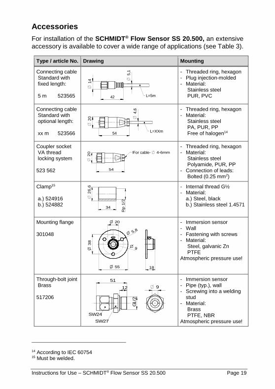
Accessories
For installation of the SCHMIDT® Flow Sensor SS 20.500, an extensive accessory is available to cover a wide range of applications (see Table 3).
Type / article No. Drawing Mounting
Connecting cable Standard with fixed length: 5 m 523565
- Threaded ring, hexagon - Plug injection-molded - Material:
Stainless steel PUR, PVC
Connecting cable Standard with optional length: xx m 523566
- Threaded ring, hexagon - Material:
Stainless steel PA, PUR, PP Free of halogen14
Coupler socket VA thread locking system 523 562
- Threaded ring, hexagon - Material:
Stainless steel Polyamide, PUR, PP - Connection of leads: Bolted (0.25 mm2)
Clamp15 a.) 524916 b.) 524882
- Internal thread G½ - Material:
a.) Steel, black b.) Stainless steel 1.4571
Mounting flange 301048
- Immersion sensor - Wall - Fastening with screws - Material:
Steel, galvanic Zn PTFE Atmospheric pressure use!
Through-bolt joint Brass 517206
- Immersion sensor - Pipe (typ.), wall - Screwing into a welding
stud - Material:
Brass PTFE, NBR Atmospheric pressure use!
14 According to IEC 60754 15 Must be welded.
L=5m
14
5,1
42
L=XXm
20
544
,6
für Kabel- 4-6mm
20
54
26
,6
34
Rp
1/2
55
20
38
18
5,8
9
51
12
1/2
G
SW24
SW27
9
For cable-

Instructions for Use – SCHMIDT® Flow Sensor SS 20.500 Page 20
Through-bolt joint V4A 532160
G1
/2
39
SW17
SW27
14 Ø 9,2+0,1
- Immersion sensor - Pipe (typ.), wall - Screwing into a welding
stud - Material:
Stainless steel 1.4571 PTFE
Atmospheric pressure use!
Through-bolt joint Brass16 a.) 524891 b.) 524919
- Immersion sensor - Tube (typ.), wall - Screwing into a welding
stud - Material:
FKM a.) Brass c.) Stainless steel
Pressure-tight up to 10 bar!
Wall mounting flange 520181
- Immersion sensor - (plane) wall - Screw on with 2 screws - Material:
Stainless steel 1.4401 PTFE, NBR
Atmospheric pressure use (pressure-tight ≤ 500 mbar)
Table 3
Notes:
The supplied connecting cables generally consist of media-resistant materials (thread ring made of stainless steel, sheathing and enclo-sure made of PUR).
The connecting cable with fixed length is not free of halogen.
The connecting cable with adjustable length (lead insulation made of modified PP) as well as the coupler socket is free of halogen.
All mounting fixtures fasten the sensor by means of frictional clamp-ing. This enables stepless positioning of the sensor in the holder con-cerning its immersion depth and axial adjustment. Accordingly, posi-tioning and alignment of the sensor tip in the flow field must be carried out with great care. Make sure to tighten fastening screw properly, especially for applications with overpressure.
16 Including pressure protection kit.

Instructions for Use – SCHMIDT® Flow Sensor SS 20.500 Page 21
4 Electrical connection
During electrical installation ensure that no voltage is applied and inadvertent activation is not possible.
The sensor is equipped with a plug-in connector which is firmly integrated in its enclosure with following features:
Number of connection pins: 5 Type: male Fastening of connecting cable: M12 thread (spigot nut at the cable), A-coded Type of protection: IP67 (with screwed cable) Model: Binder, series 713 Pin numbering:
View on connector of sensor
Figure 4-1
Pin assignment of the plug-in connector is given in the following Table 4.
Pin Designation Function Lead colour
1 Power Operating voltage DC: +UB Operating voltage AC: U~
brown
2 Analog TM Output signal: Temperature of medium white
3 GND Operating voltage DC: GND (-UB) Operating voltage AC: U~
blue
4 Analog wN Output signal: Standard flow velocity black
5 AGND Ground connection of analog outputs gray
Table 4
The specified lead colours are valid if one of the SCHMIDT® connecting cables is used (see subchapter "Accessories").
The appropriate protection class III (SELV) respective PELV (ac-cording EN 50178) has to be considered.
!
1 2
4 35
!

Instructions for Use – SCHMIDT® Flow Sensor SS 20.500 Page 22
Operating voltage
For proper operation the sensor requires DC or AC voltage with a nominal value of 24 V(eff) with permitted tolerance of ±20 %.
Deviating values lead to deactivation of the measuring function or even to defects and, therefore, should be avoided. As far as it is functionally pos-sible, the LED indication reports the faulty operational conditions (see chapter 5 Signalling).
Only operate sensor within the defined range of operating volt-age (24 V DC / AC ± 20 %).
Undervoltage may result in malfunction; overvoltage may lead to irreversible damage.
The operating current of the sensor (including signal currents) is worst case17 less than 170 mA; typically, it is in the range of 50 to 100 mA.
Specifications for operating voltage apply for the connection at the sensor. Voltage drops generated due to line resistances must be considered by the customer.
Wiring of analog outputs
Both analog outputs for flow and temperature are designed as high-side driver with "Auto-U/I" feature and have a permanent short-circuit protec-tion against both rails of the operating voltage.
Use of only one analog output
It is recommended to connect the same resistance value to both ana-log outputs, even if only one of them is used. For example, if only the “flow” analog output is operated as current output with a resistance value of a few ohms, it is recommended to connect the other analog output (“temperature”) with the same resistance value or directly to AGND.
Nominal operation
The load resistance RL must be connected between the corresponding signal output and the electronic reference potential of the sensor (see Figure 4-2). In general, AGND should be selected as measuring refer-ence potential. The supply line GND (UB,DC) can also be used as ref-erence potential; however, ground offset can cause significant meas-urement errors using the signal output mode "Voltage".
17 Including both signal outputs with 22 mA (maximum measuring values), operating volt-age at minimum.
!

Instructions for Use – SCHMIDT® Flow Sensor SS 20.500 Page 23
In general, AGND should be selected as measuring refer-ence potential for signal outputs.
Figure 4-2
Depending on the value of the load resistance RL the electronics switches automatically between its operation as voltage interface (mode: U) or current interface (mode: I), hence, the designation „Auto-
U/I“. The switching threshold is within the range of 500 to 550 (for details refer to chapter 5 Signalling). However, a low resistance value in voltage mode may cause significant voltage losses via line re-sistances RW,S, which can lead to measurement errors.
For voltage mode it is recommended to use a measuring
resistance of at least 10 k.
The maximum load capacity is 10 nF.
Short-circuit mode
In case of a short circuit against the positive rail of the operating DC voltage (+UB) resp. against both rails during the positive AC half-cycle the signal output is switched off. Due to internal measuring re-sistances it is possible that a current of max. 15 mA flows into the sensor output (referred to AGND).
In case of a short-circuit against the negative rail (GND) at DC supply or against both rails during a negative AC half-cycle the output
switches to current mode (RL is calculated for 0 ) and provides the required signal current.
If the signal output is connected to +UB via a resistance or to one of the rails for AC voltage, the RL value is calculated incorrectly which leads to false measurement values or cyclic switching of the signal modes with the frequency of the AC voltage.
!
V
wN
RL
TM
AGND
GND / U~
+
-
+U / U~B
A A
RL V
RW,B
RW,S
RW,S
RW,B
CL
!

Instructions for Use – SCHMIDT® Flow Sensor SS 20.500 Page 24
5 Signalling
Light emitting diodes (LED)
The SCHMIDT® Flow Sensor SS 20.500 has four Duo-LEDs18 (see Fig-ure 5-1) that are either indicating flow velocity during error-free operation in a quantitative way or signal the error cause (see Table 5).
Figure 5-1
No. State LED 1 LED 2 LED 3 LED 4
1 Ready for operation & flow < 5 % 19
2 Flow > 5 %
3 Flow > 20 %
4 Flow > 50 %
5 Flow > 80 %
6 Flow > 100 % = overflow
7 Sensor element defective
8 Supply voltage too low
9 Supply voltage too high
10 Electronic temperature too low
11 Electronic temperature too high
12 Medium temperature too low
13 Medium temperature too high
Table 5
LED off LED shines orange
LED shines green LED flashes red (approx. 1 Hz)
18 Component with two separately controllable LEDs (red and green) that generate in com-bination the mixed color orange.
19 „%“ of the end of measuring range
LED 1

Instructions for Use – SCHMIDT® Flow Sensor SS 20.500 Page 25
Analog outputs
Switching characteristic Auto-U/I
Range of resistance value RL Signalling mode Signalling range
≤ 500 (550) Current (I) 4 ... 20 mA
> 500 (550) Voltage (U) 0 ... 10 V
A hysteresis of approx. 50 ensures a stable transition behavior (see Figure 5-2).
Figure 5-2
Depending on the provided output signal accuracy of the mode switch-ing point detection can be decreased. Therefore, it is recommended to select the resistance in such a way that safe detection can be main-
tained (< 300 for current mode and > 1 k for voltage mode).
To detect possible alternating load for an actual zero signal, the elec-tronics generates test pulses that correspond to an effective value of approx. 1 mV. However, latest measuring devices may trigger in re-sponse to such a pulse in DC voltage measuring mode and display short-term measuring values of up to 20 mV. In this case it is re-com-mended to install an RC filter at the measuring input with a time con-stant of 20 … 100 ms.
Error signaling
In current mode the interface outputs 2 mA20.
In voltage mode the output switches to 0 V.
Representation of measuring range
The measuring range of the corresponding measuring value is mapped in a linear way to the signal range of its associated analog output specific for this mode.
20 In accordance with NAMUR specification.

Instructions for Use – SCHMIDT® Flow Sensor SS 20.500 Page 26
For flow measurement the measuring ranges from zero flow to the selectable end of the measuring range wN,max (see Table 6).
Voltage mode (U) Current mode (I)
𝑤𝑁 =𝑤𝑁,𝑚𝑎𝑥
10 𝑉∙ 𝑈𝑂𝑢𝑡,𝑤𝑁
𝑤𝑁 =𝑤𝑁,𝑚𝑎𝑥
16 𝑚𝐴∙ (𝐼𝑂𝑢𝑡,𝑤𝑁
− 4 𝑚𝐴)
Table 6 Standard for representation of flow measurement
The measuring range of the medium temperature TM is specified be-tween -40 and +85 °C (see Table 7).
Voltage mode (U) Current mode (I)
𝑤𝑁 = (125
10 𝑉∙ 𝑈𝑂𝑢𝑡,𝑇𝑀
− 40) °𝐶 𝑤𝑁 = [125
16 𝑚𝐴∙ (𝐼𝑂𝑢𝑡,𝑇𝑀
− 4 𝑚𝐴) − 40] °𝐶
Table 7 Standard for representation of medium temperature measurement
Note regarding commissioning:
The temperature output normally provides approx. 5 V resp. 12 mA because the typical prevailing room temperature of approx. 20 °C cor-responds to about half of the measuring range.
UOut
[V]
0 110 wN [%]
10
020
11
40 8060 100
4
2
6
8
110 wN [%]0
20 40 8060 100
IOut
[mA]
20
4
21,6
12
8
16
UOut
[V]
0 90-40 TM [°C]
10
4
2
20
11
40 + 8560-20
6
8
IOut
[mA]
0 90-40 TM [°C]
20
4
8
20
22
40 + 8560-20
1212
16
2
Instructions for Use – SCHMIDT® Flow Sensor SS 20.500 Page 27
Exceeding measuring range of flow wN
Measuring values higher than wN,max are still output in a linear way up to 110 % of the signaling range (this corresponds to maximum output of 11 V resp. 21,6 mA, see images in Table 6). For higher flow velocity values the output signal remains constant.
Error signaling does not take place because damage of the sensor is unlikely.
Medium temperature TM beyond specification range
Operation beyond specified limits can lead to damage of the measur-ing probe and, therefore, is seen as a critical error. This leads to the following reaction depending on the temperature limit (also refer to images in Table 7):
o Medium temperature below TM,min = -40 °C:
Analog output for TM switches to error signaling (0 V resp. 2 mA)21. Measuring function of the flow velocity is switched off; its analog output also reports an error (0 V resp. 2 mA).
o Medium temperature above TM,max = +85 °C:
Up to 90 °C TM is still output in a linear way (this corresponds to 10.4 V resp. 20.6 mA), to enable an overshooting of heating con-trol. The flow velocity is measured and displayed further on. Above this critical limit20 flow measurement is switched off and its analog output switches to error signaling (0 V resp. 2 mA). The signal output for TM jumps directly to its maximum values of 11 V resp. 22 mA which differs from standard error signaling. This allows avoiding a problematic positive feedback in case of a heating control which uses the temperature sensor of the flow sensor. Standard signaling of 0 V (possibly 2 mA) could be iden-tified by the control as a very low temperature of the medium, this would lead to further heating.
21 Switching hysteresis for the threshold is approx. 2 K.

Instructions for Use – SCHMIDT® Flow Sensor SS 20.500 Page 28
6 Commissioning
Before switching on the SCHMIDT® Flow Sensor SS 20.500 the following checks have to be carried out:
Mechanical mounting:
o Immersion depth of sensor probe and alignment of enclosure.
o Tightening of fastening screw respective spigot nut.
o Installation of pressure safety devices.
For measurements in media with overpressure check if fas-tening screw is tightened properly and pressure safety de-vices are installed.
Connecting cable:
o Proper connection in the field (switch cabinet or similar).
o Tightness between sensor connector and connecting cable (flat seal must be inserted correctly into the female cable connector).
o Tight fit of spigot nut on connecting cable connector at sensor en-closure.
After turning on the operating voltage, the sensor reports initialization by switching on all four LEDs simultaneously for one second at a time, se-quentially in the colors red, orange and green.
If the sensor detects a problem during initialization, it reports the problem after initialization according to Table 5. An extensive overview of error causes and troubleshooting measures is given in Table 9.
If the sensor is in the correct operational state after initialization it switches into measuring mode. The indication of flow velocity (both LEDs and ana-log output) switches for a short period to maximum and settles after ap-prox. 10 s at the rough measuring value. Correct measuring values can be expected after approx. 30 s if the sensor probe already has the medium temperature. Otherwise, the process will last longer until the probe has reached the medium temperature.
!

Instructions for Use – SCHMIDT® Flow Sensor SS 20.500 Page 29
7 Information concerning operation
Ambient condition temperature
The SCHMIDT® Flow Sensor SS 20.500 monitors the temperature of both medium and electronics. As soon as one limit of the specified temperature ranges is exceeded, the sensor switches off one or both measuring func-tions associated with the medium depending on the situation and report the corresponding error. As soon as proper operational conditions are re-stored, the sensor resumes normal function.
Even a short-term overshooting of the safety limit values can lead to per-manent damage of the sensor which must be avoided by all means. On the other hand, falling below is less critical but leads to an increased brit-tleness of sensitive components, for example of the sensor tip or connect-ing cable.
Even short-term overshooting of operating temperatures can cause irreversible damage to the sensor.
Ambient condition pressure
The flow sensor SS 20.500 exhibits a minor dependency on overpressure pop close to zero flow. At wN = 0 m/s the sensor signals with increasing overpressure an increasing flow wN,Sensor,0,Op > 0 m/s in a proportional way. This deviation decreases rapidly with increasing flow and diminishes at wN,Sensor,C showing correct measurements with no further influence from pressure (see Table 8).
The residual dependence of the pressure can be calculated to:
𝑤𝑁,𝑆𝑒𝑛𝑠𝑜𝑟,0,𝑂𝑝 = 0.04𝑚
𝑠⁄
𝑏𝑎𝑟∙ 𝑝𝑂𝑃
𝑤𝑁,𝑆𝑒𝑛𝑠𝑜𝑟,𝐶 = 2 ∙ 𝑤𝑁,𝑆𝑒𝑛𝑠𝑜𝑟,0,𝑂𝑝
Table 8 Dependence of sensor signal near zero flow
!
pOp
[bar] 0,0 0,1 0,2 0,3 0,4 0,6 0,8 1,0
0 0,00 0,00 0,20 0,30 0,40 0,60 0,8 1,0
2 0,08 0,09 0,20 0,30 0,40 0,60 0,8 1,0
4 0,16 0,18 0,26 0,31 0,40 0,60 0,8 1,0
6 0,24 0,26 0,34 0,39 0,44 0,60 0,8 1,0
8 0,32 0,35 0,42 0,47 0,52 0,62 0,8 1,0
10 0,40 0,44 0,50 0,55 0,60 0,70 0,8 1,0
Sensor signal: wN,Sensor [m/s]
@ wN [m/s]

Instructions for Use – SCHMIDT® Flow Sensor SS 20.500 Page 30
Ambient condition medium
The SCHMIDT® Flow Sensor SS 20.500 is especially suitable for impure gases that contain dust, non-abrasive particles or gaseous fractions such as vapors, oils or chemically aggressive components.
Deposits or other soiling must be detected during regular inspections and removed by cleaning because it can cause distortion of measurement re-sults (see chapter 8 Service information).
Soiling or other deposits on the probe head cause false meas-urement results. Therefore, the sensor must be checked for contaminations at regular intervals and cleaned if necessary.
The coated probe (coating versions: black PU-derivate or transparent Parylene) has particularly high chemical media resistance against organic solvents, acids and caustics in liquid or gaseous state, for example:
Acetone, ethyl acetate, methyl ethyl ketone, perchlorethylene, xylene, al-cohols, ammonia, petrol, motor oil (50 °C), cutting oil (50 °C), sodium hy-droxide, acetic acid, hydrochloric acid, sulphuric acid and more.
The suitability of the mentioned above or other similar chemicals must be checked in every individual case due to different ambient conditions.
Condensing liquid fractions in gases or even immersion into liquids do not damage the probe (as long as there is no damage due to corrosion or similar). However, the significantly higher heating capacity of liquids distort measuring results seriously (e.g. when immersing into water the flow indi-cation goes to maximum) but after drying of the sensor tip normal meas-uring function is available again.
(Condensating) liquid on the measuring probe causes serious measurement distortions. After drying the correct measuring function is restored.
Sterilizability
Both uncoated and coated sensor can be sterilized during operation.
Alcohols (drying without leaving residues) and hydrogen peroxide22 are approved and certified as disinfectants.
Other disinfectants must be checked by the customer if necessary.
22 Use of hydrogen peroxide only with uncoated version
!
!

Instructions for Use – SCHMIDT® Flow Sensor SS 20.500 Page 31
8 Service information
Maintenance
Heavy soiling of the sensor tip may distort the measured value. Therefore, the sensor tip must be checked for soiling at regular intervals. If the soiling is visible, the sensor can be cleaned as described below.
Cleaning the sensor tip
To clean the sensor tip from dust or soiling move it carefully in warm water with cleaning agent or other permitted cleaning fluid (e.g. alcohol). Persis-tent incrustations or gratings can be previously softened by prolonged im-mersion and then removed by means of a soft brush. Avoid applying force to the sensitive probe tip.
The sensor tip is a sensitive measuring system. During manual cleaning proceed with great care.
Before putting it into operation again wait until the sensor tip is completely dry.
Troubleshooting
Possible errors (error images) are listed in the Table 9. There is also a description of the way to detect an error. Furthermore, possible causes and measures to eliminate the error are listed.
Causes of any error signalling have to be eliminated imme-diately. Significant exceeding or falling below the permitted operating limits can result in permanent damage to the sensor.
!
!

Instructions for Use – SCHMIDT® Flow Sensor SS 20.500 Page 32
Error image Possible causes Troubleshooting
Problems with supply UB: No UB available Wrong polarity of
DC-supply UB < 15 V Sensor is defective
Plug-in connector screwed on correctly?
Supply voltage connected?
Voltage at sensor plug available (cable break)?
Power supply large enough?
No LED is shining Both signal outputs at zero
Start sequence is repeated continuously (all LEDs flashes simultaneously red - yellow - green)
UB unstable: Power cannot supply
switch-on current Other consumers over-
load power source
Cable resistance too high
Supply voltage at sensor stable?
Power of supply unit sufficiently?
Voltage losses over cable negligible?
Sensor element defective Send in sensor for repair
Electronic temperature too low
Increase temperature of environment
Electronic temperature too high
Decrease temperature of environment
Medium temperature too low
Increase medium temperature
Medium temperature too high
Reduce medium temperature
Flow signal wN is too large / small
Measuring range too small / large I-mode instead of U-mode Measuring medium does not correspond to air Sensor head is soiled
Check sensor configuration Check measuring resistance Gas correction considered? Clean sensor tip
Flow signal wN is fluctuat-ing
UB unstable Sensor tip is not in opti-mum position Let-in or let-out distance is too short Strong fluctuations of pres-sure or temperature
Check voltage supply Check installation conditions Check operating parameters
Analog signal in U-mode has offset or is noisy
Measuring resistance of signal output is at GND
Connect measuring resistance to AGND
Analog signal permanently at max.
Measuring resistance of signal output is at UB (DC)
Connect measuring resistance to AGND
Analog signal switches be-tween min. and max.
Measuring resistance of signal output is at GNDAC
Connect measuring resistance to AGND
Table 9

Instructions for Use – SCHMIDT® Flow Sensor SS 20.500 Page 33
Transport / shipment of the sensor
Before transportation or shipment of the sensor the delivered protective cap must be placed on the sensor tip. Avoid soiling or mechanical stress.
Calibration
If the customer has made no other provisions, we recommend repeating the calibration at a 12-month interval. For this purpose the sensor must be sent in to the manufacturer.
Spare parts or repair
No spare parts are available, since a repair is only possible at the manu-facturer's facility. In case of defects, the sensors must be sent in to the supplier for repair.
A completed declaration of decontamination must be attached.
The “Declaration of decontamination” form is enclosed with the sensor and can also be downloaded from
www.schmidt-sensors.com or www.schmidttechnology.com
under “Service & Support”.
When the sensor is used in systems important for operation, we recom-mend you to keep a replacement sensor in stock.
Test certificates and material certificates
Every new sensor is accompanied by a certificate of compliance according to EN 10204-2.1. Material certificates are not available.
Upon request, we shall prepare, at a charge, a factory calibration certifi-cate, traceable to national standards.
Instructions for Use – SCHMIDT® Flow Sensor SS 20.500 Page 34
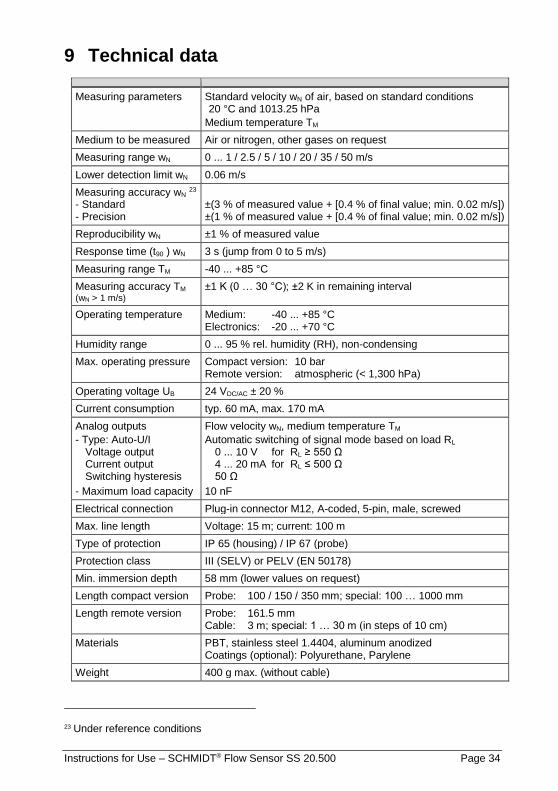
9 Technical data
Measuring parameters Standard velocity wN of air, based on standard conditions 20 °C and 1013.25 hPa
Medium temperature TM
Medium to be measured Air or nitrogen, other gases on request
Measuring range wN 0 ... 1 / 2.5 / 5 / 10 / 20 / 35 / 50 m/s
Lower detection limit wN 0.06 m/s
Measuring accuracy wN 23 - Standard - Precision
±(3 % of measured value + [0.4 % of final value; min. 0.02 m/s]) ±(1 % of measured value + [0.4 % of final value; min. 0.02 m/s])
Reproducibility wN ±1 % of measured value
Response time (t90 ) wN 3 s (jump from 0 to 5 m/s)
Measuring range TM -40 ... +85 °C
Measuring accuracy TM (wN > 1 m/s)
±1 K (0 … 30 °C); ±2 K in remaining interval
Operating temperature Medium: -40 ... +85 °C Electronics: -20 ... +70 °C
Humidity range 0 ... 95 % rel. humidity (RH), non-condensing
Max. operating pressure Compact version: 10 bar Remote version: atmospheric (< 1,300 hPa)
Operating voltage UB 24 VDC/AC ± 20 %
Current consumption typ. 60 mA, max. 170 mA
Analog outputs
- Type: Auto-U/I Voltage output Current output Switching hysteresis
- Maximum load capacity
Flow velocity wN, medium temperature TM
Automatic switching of signal mode based on load RL 0 ... 10 V for RL ≥ 550 Ω 4 ... 20 mA for RL ≤ 500 Ω 50 Ω
10 nF
Electrical connection Plug-in connector M12, A-coded, 5-pin, male, screwed
Max. line length Voltage: 15 m; current: 100 m
Type of protection IP 65 (housing) / IP 67 (probe)
Protection class III (SELV) or PELV (EN 50178)
Min. immersion depth 58 mm (lower values on request)
Length compact version Probe: 100 / 150 / 350 mm; special: 100 … 1000 mm
Length remote version Probe: 161.5 mm Cable: 3 m; special: 1 … 30 m (in steps of 10 cm)
Materials PBT, stainless steel 1.4404, aluminum anodized Coatings (optional): Polyurethane, Parylene
Weight 400 g max. (without cable)
23 Under reference conditions

Instructions for Use – SCHMIDT® Flow Sensor SS 20.500 Page 35
10 Declaration of conformity

Instructions for Use – SCHMIDT® Flow Sensor SS 20.500 Page 36
SCHMIDT Technology GmbH Feldbergstraße 1 78112 St. Georgen Germany
Phone +49 (0)7724 / 899-0 Fax +49 (0)7724 / 899-101 Email [email protected] URL www.schmidt-sensors.com