SCHME OF EVALUTION
23
Transcript of SCHME OF EVALUTION

SCHME OF EVALUTION
II/IV B.Tech(Regular) DEGREE EXAMINATION
April,2017 Electronics & Instrumentation Engineering
14EI 403 Electrical Technology Max.Marks:60 marks
-----------------------------------------------------------------------------------------------------------
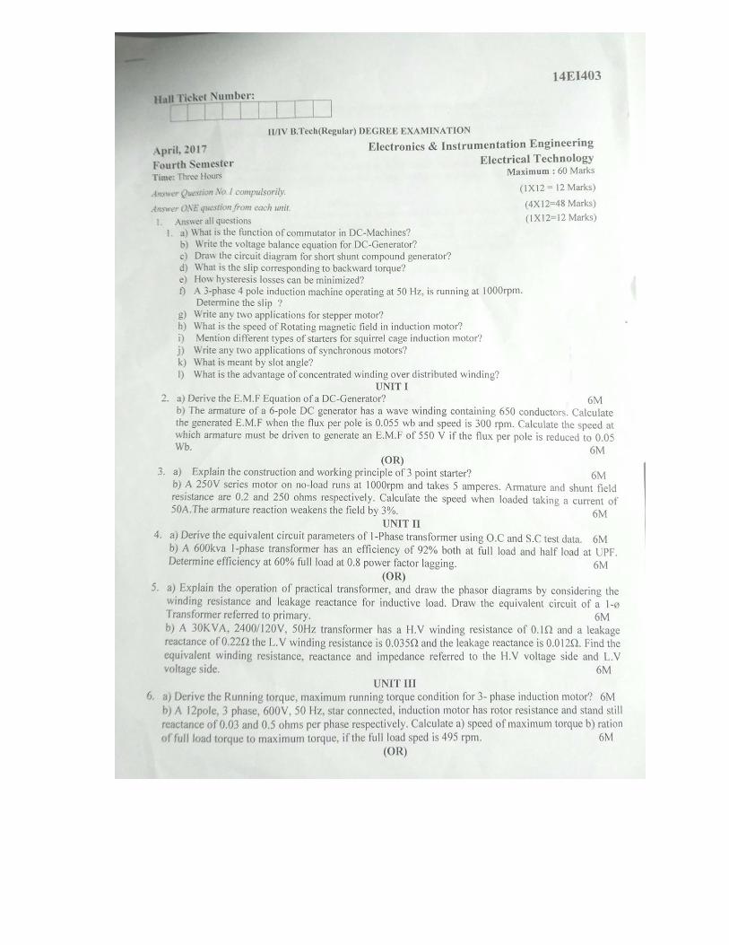
1.Answer all questions. (1×12=12Marks)
Answer one question from each unit. (4×12=48Marks)
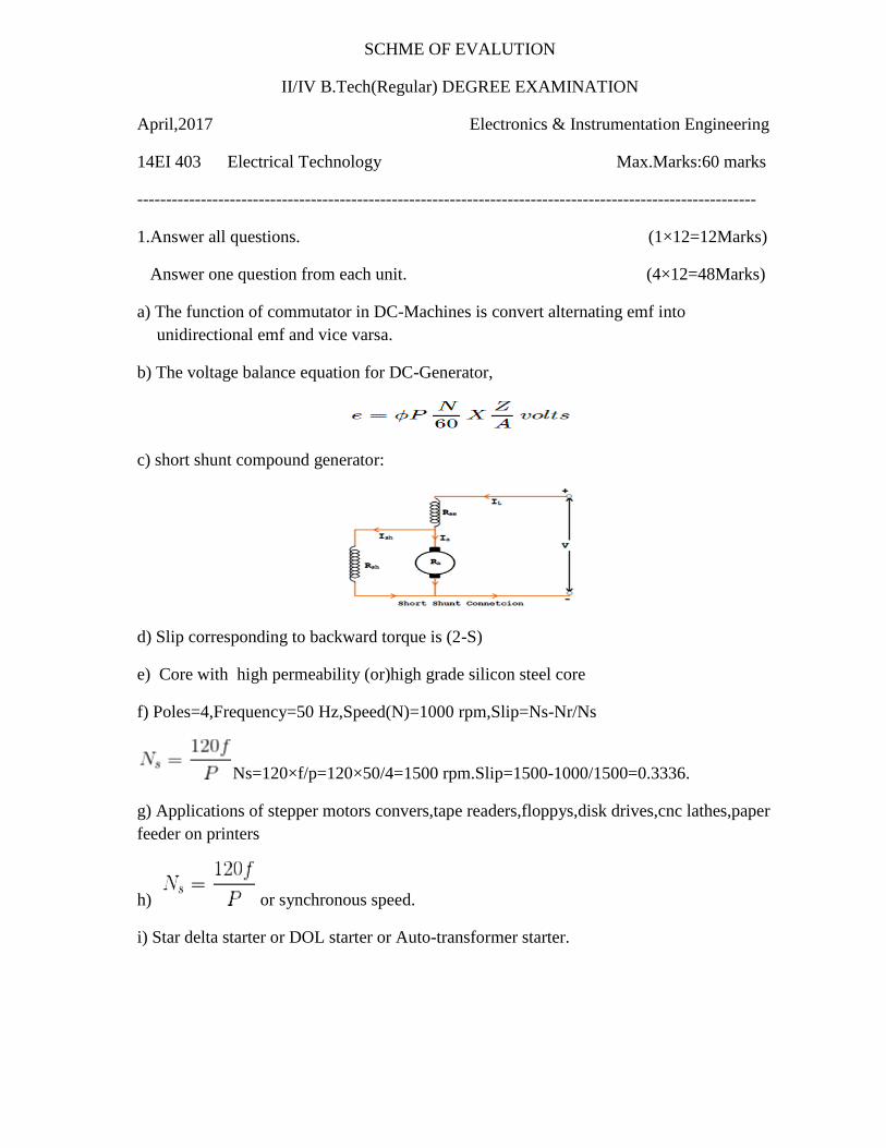
a) The function of commutator in DC-Machines is convert alternating emf into
unidirectional emf and vice varsa.
b) The voltage balance equation for DC-Generator,
c) short shunt compound generator:
d) Slip corresponding to backward torque is (2-S)
e) Core with high permeability (or)high grade silicon steel core
f) Poles=4,Frequency=50 Hz,Speed(N)=1000 rpm,Slip=Ns-Nr/Ns
Ns=120×f/p=120×50/4=1500 rpm.Slip=1500-1000/1500=0.3336.
g) Applications of stepper motors convers,tape readers,floppys,disk drives,cnc lathes,paper
feeder on printers
h) or synchronous speed.
i) Star delta starter or DOL starter or Auto-transformer starter.
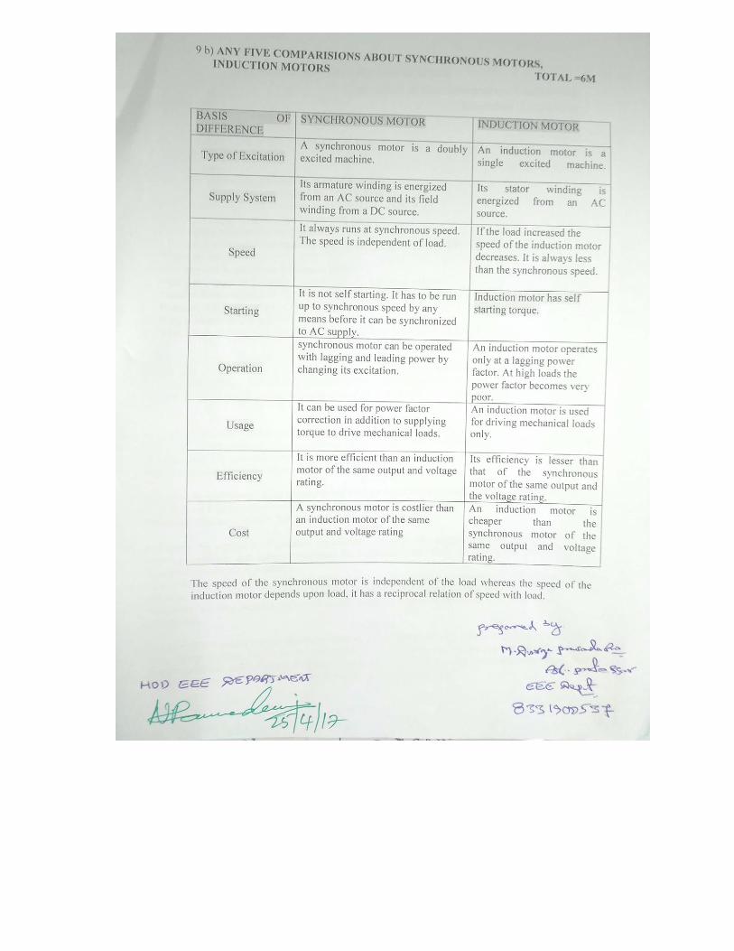
j) Application of Synchronous Motor:-i) Synchronous motor having no load connected to its
shaft is used for power factor improvement.
ii) Synchronous motor finds application where operating speed is less (around 500 rpm)
and high power is required. For power requirement from 35 kW to 2500 KW, the size,
weight and cost of the corresponding three phase induction motor is very high. Hence
these motors are preferably used. Ex- Reciprocating pump, compressor, rolling mills.
k) This is the angle subtended by the single slot. β=1800/No. of slots/pole
l) i) Heat dissipation is less ii) space required for the armature winding less iii) Size of the
machine is less.
UNIT-I
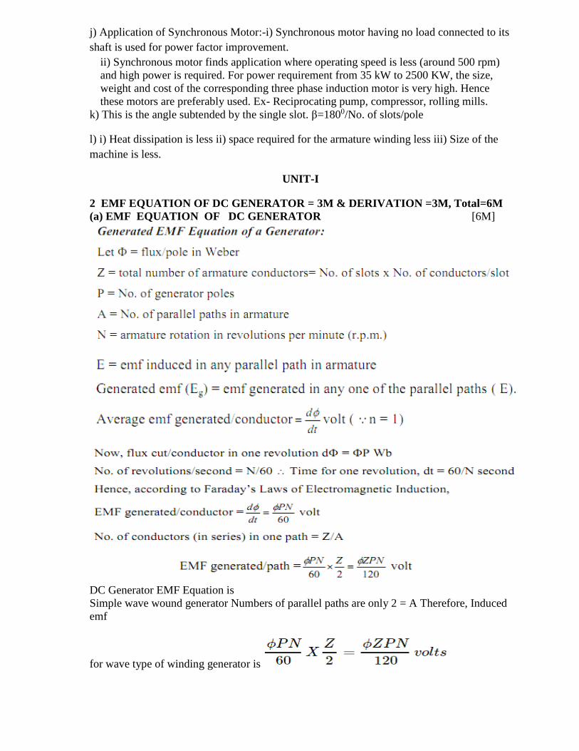
2 EMF EQUATION OF DC GENERATOR = 3M & DERIVATION =3M, Total=6M
(a) EMF EQUATION OF DC GENERATOR [6M]
DC Generator EMF Equation is
Simple wave wound generator Numbers of parallel paths are only 2 = A Therefore, Induced
emf
for wave type of winding generator is

Simple lap-wound generator Here, number of parallel paths is equal to number of
conductors in one path i.e. P = A Therefore, Induced emf for lap-wound generator is
2 b) CALCULATED EMF = 3M, NEW SPEED = 3M TOTAL=6M
(OR)
3 EXPLANATION=2M,OPERATION=2M,DIAGRAM OF 3-POINT STARTER=2M (6M)
a) Three Point Starter:
Construction:
Working Of Three Point Starter:
1) Initially when a DC supply is switched ON with handle in the OFF position.
2) The handle is now moved clockwise to the first stud, the shunt field winding is directly
connected across the supply while the whole starting resistance is inserted in series with the
armature circuit.
3) As the handle is gradually moved over to the final stud, the starting resistance is cut out
of the armature circuit in steps. The handle is now held magnetically by the no volt release
coil which is energized by shunt field current.
4) If the supply voltage is suddenly interrupted or if the field excitation is accidently cut, the
no volt release coil is demagnetized and the handle goes back to the OFF position under the
pull of the spring. If no volt coil were not used, then in case of failure of supply. The handle
would remain on the final stud. If then supply is restored, the motor will be directly
connected across the supply, resulting in an excessive armature current.
5) If the motor is overloaded (or any fault occurs) it will draw excessive current from the
supply. This current will increase the ampere turns of the overload release coil and pull the
armature, thus short circuited the no volt release coil. The no volt coil is demagnetized and
the handle is pulled to the OFF position by the spring .thus the motor is automatically
disconnected from the supply.
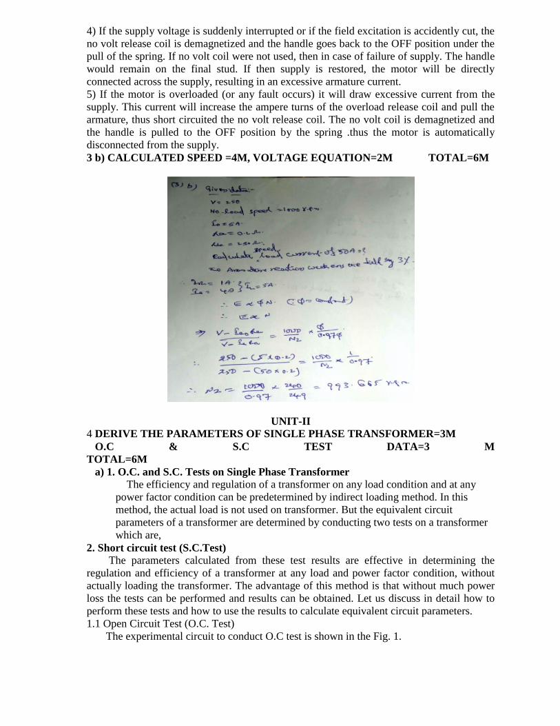
3 b) CALCULATED SPEED =4M, VOLTAGE EQUATION=2M TOTAL=6M
UNIT-II
4 DERIVE THE PARAMETERS OF SINGLE PHASE TRANSFORMER=3M
O.C & S.C TEST DATA=3 M
TOTAL=6M
a) 1. O.C. and S.C. Tests on Single Phase Transformer
The efficiency and regulation of a transformer on any load condition and at any
power factor condition can be predetermined by indirect loading method. In this
method, the actual load is not used on transformer. But the equivalent circuit
parameters of a transformer are determined by conducting two tests on a transformer
which are,
2. Short circuit test (S.C.Test)
The parameters calculated from these test results are effective in determining the
regulation and efficiency of a transformer at any load and power factor condition, without
actually loading the transformer. The advantage of this method is that without much power
loss the tests can be performed and results can be obtained. Let us discuss in detail how to
perform these tests and how to use the results to calculate equivalent circuit parameters.
1.1 Open Circuit Test (O.C. Test)
The experimental circuit to conduct O.C test is shown in the Fig. 1.

Fig 1. Experimental circuit for O.C. test
The transformer primary is connected to a.c. supply through ammeter, wattmeter and
variac. The secondary of transformer is kept open. Usually low voltage side is used as
primary and high voltage side as secondary to conduct O.C test.
The primary is excited by rated voltage, which is adjusted precisely with the help of a
variac. The wattmeter measures input power. The ammeter measures input current. The
voltemeter gives the value of rated primary voltage applied at rated frequency.
Sometimes a voltmeter may be connected across secondary to measure secondary
voltage which is V2 = E2 when primary is supplied with rated voltage. As voltmeter
resistance is very high, though voltmeter is connected, secondary is treated to be open
circuit as voltmeter current is always negligibly small.
When the primary voltage is adjusted to its rated value with the help of variac, readings
of ammeter and wattmeter are to be recorded.
The observation table is as follows
Vo = Rated voltage
Wo = Input power
Io = Input current = no load current
As transformer secondary is open, it is on no load. So current drawn by the primary is
no load current Io. The two components of this no load current are,
Im = Io sin Φo
Ic = Io cos Φo
where cos Φo = No load power factor
And hence power input can be written as,
Wo = Vo Io cos Φo
The phasor diagram is shown in the Fig. 2.
Fig. 2
As secondary is open, I2 = 0. Thus its reflected current on primary is also zero. So we
have primary current I1 =Io. The transformer no load current is always very small, hardly 2
to 4 % of its full load value. As I2 = 0, secondary copper losses are zero. And I1 = Io is very
low hence copper losses on primary are also very very low. Thus the total copper losses in
O.C. test are negligibly small. As against this the input voltage is rated at rated frequency
hence flux density in the core is at its maximum value. Hence iron losses are at rated
voltage. As output power is zero and copper losses are very low, the total input power is
used to supply iron losses. This power is measured by the wattmeter i.e. Wo. Hence the
wattmeter in O.C. test gives iron losses which remain constant for all the loads.
... Wo = Pi = Iron losses
Calculations : We know that,
Wo = Vo Io cos Φ
cos Φo = Wo /(Vo Io ) = no load power factor
Once cos Φo is known we can obtain,
Ic = Io cos Φo
and Im = Io sin Φo
Once Ic and Im are known we can determine exciting circuit parameters as,
Ro = Vo /Ic Ω
and Xo = Vo /Im Ω
Note : The no load power factor cos Φo is very low hence wattmeter used must be low
power factor type otherwise there might be error in the results. If the meters are connected
on secondary and primary is kept open then from O.C. test we get Ro'and Xo' with which we
can obtain Ro and Xo knowing the transformation ratio K.
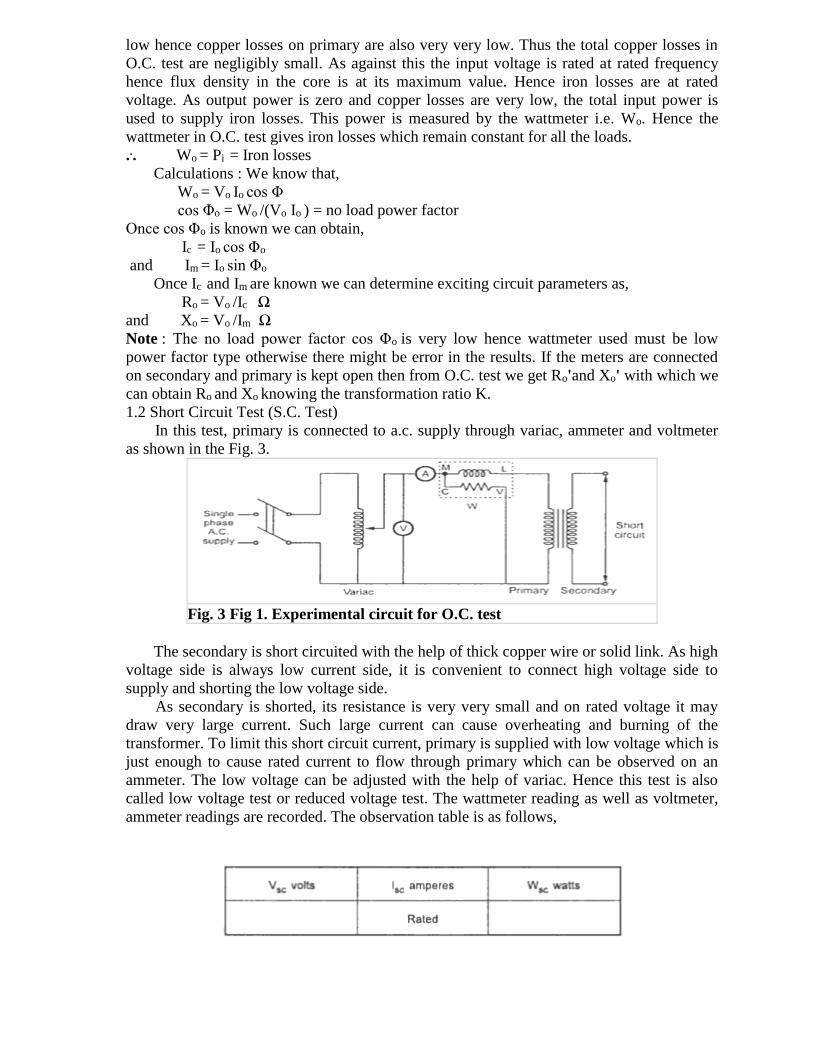
1.2 Short Circuit Test (S.C. Test)
In this test, primary is connected to a.c. supply through variac, ammeter and voltmeter
as shown in the Fig. 3.
Fig. 3 Fig 1. Experimental circuit for O.C. test
The secondary is short circuited with the help of thick copper wire or solid link. As high
voltage side is always low current side, it is convenient to connect high voltage side to
supply and shorting the low voltage side.
As secondary is shorted, its resistance is very very small and on rated voltage it may
draw very large current. Such large current can cause overheating and burning of the
transformer. To limit this short circuit current, primary is supplied with low voltage which is
just enough to cause rated current to flow through primary which can be observed on an
ammeter. The low voltage can be adjusted with the help of variac. Hence this test is also
called low voltage test or reduced voltage test. The wattmeter reading as well as voltmeter,
ammeter readings are recorded. The observation table is as follows,
Now the current flowing through the windings are rated current hence the total copper
loss is full load copper loss. Now the voltage supplied is low which is a small fraction of the
rated voltage. The iron losses are function of applied voltage. So the iron losses in reduced
voltage test are very small. Hence the wattmeter reading is the power loss which is equal to
full load copper losses as iron losses are very low.
... Wsc = (Pcu) F.L. = Full load copper loss
Calculations : From S.C. test readings we can write,
Wsc = Vsc Isc cos Φsc
... cos Φsc = Vsc Isc /Wsc = short circuit power factor
Wsc = Isc2 R1e = copper loss
... R1e =Wsc /Isc2
while Z1e =Vsc /Isc = √(R1e2
+ X1e2)
... X1e = √(Z1e
2 - R1e2)
Thus we get the equivalent circuit parameters R1e, X1e and Z1e. Knowing the
transformation ratio K, the equivalent circuit parameters referred to secondary also can be
obtained.
Note : In short, if meters are connected to primary of transformer in S.C. test, calculations
give us R1e and Z1e if meters are connected to secondary of transformer in S.C. test
calculations give us R2e and Z2e.
1.3 Calculation of Efficiency from O.C. and S.C. Tests
We know that,
From O.C. test, Wo = Pi
From S.C. test, Wsc = (Pcu) F.L.
Thus for any p.f. cos Φ2 the efficiency can be predetermined. Similarly at any load which is
fraction of full load then also efficiency can be predetermined as,
where n = fraction of full load
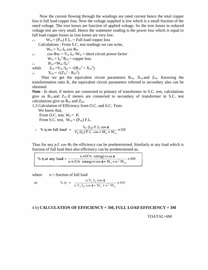
4 b) CALCULATION OF EFFICIENCY = 3M, FULL LOAD EFFICIENCY = 3M
TOATAL=6M
(OR)
5 DRAW=2M,EXPLANATION=2M,EQUIVALENT OF TRANSFORMER=2M (6M)
a) Equivalent Circuit of Transformer
Equivalent impedance of transformer is essential to be calculated because the electrical
power transformer is an electrical power system equipment for estimating different
parameters of electrical power system which may be required to calculate total internal
impedance of an electrical power transformer, viewing from primary side or secondary side
as per requirement. This calculation requires equivalent circuit of transformer referred to
primary or equivalent circuit of transformer referred to secondary sides respectively.
Percentage impedance is also very essential parameter of transformer. Special attention is to
be given to this parameter during installing a transformer in an existing electrical power
system. Percentage impedance of different power transformers should be properly matched
during parallel operation of power transformers. The percentage impedance can be derived
from equivalent impedance of transformer so, it can be said that equivalent circuit of
transformer is also required during calculation of % impedance.
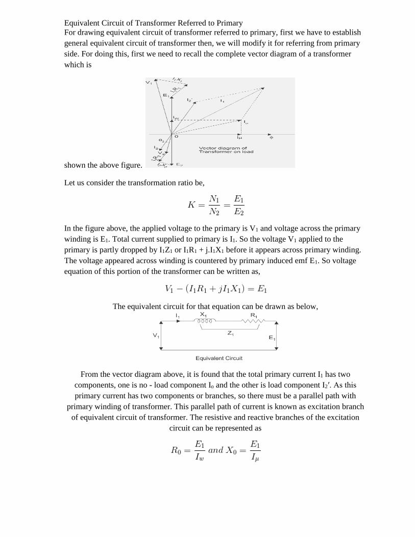
Equivalent Circuit of Transformer Referred to Primary
For drawing equivalent circuit of transformer referred to primary, first we have to establish
general equivalent circuit of transformer then, we will modify it for referring from primary
side. For doing this, first we need to recall the complete vector diagram of a transformer
which is
shown the above figure.
Let us consider the transformation ratio be,
In the figure above, the applied voltage to the primary is V1 and voltage across the primary
winding is E1. Total current supplied to primary is I1. So the voltage V1 applied to the
primary is partly dropped by I1Z1 or I1R1 + j.I1X1 before it appears across primary winding.
The voltage appeared across winding is countered by primary induced emf E1. So voltage
equation of this portion of the transformer can be written as,
The equivalent circuit for that equation can be drawn as below,
From the vector diagram above, it is found that the total primary current I1 has two
components, one is no - load component Io and the other is load component I2′. As this
primary current has two components or branches, so there must be a parallel path with
primary winding of transformer. This parallel path of current is known as excitation branch
of equivalent circuit of transformer. The resistive and reactive branches of the excitation
circuit can be represented as
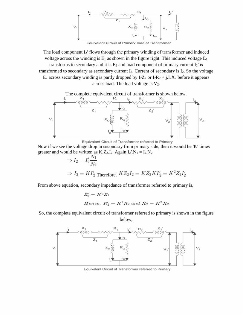
The load component I2′ flows through the primary winding of transformer and induced
voltage across the winding is E1 as shown in the figure right. This induced voltage E1
transforms to secondary and it is E2 and load component of primary current I2′ is
transformed to secondary as secondary current I2. Current of secondary is I2. So the voltage
E2 across secondary winding is partly dropped by I2Z2 or I2R2 + j.I2X2 before it appears
across load. The load voltage is V2.
The complete equivalent circuit of transformer is shown below.
Now if we see the voltage drop in secondary from primary side, then it would be ′K′ times
greater and would be written as K.Z2.I2. Again I2′.N1 = I2.N2
Therefore,
From above equation, secondary impedance of transformer referred to primary is,
So, the complete equivalent circuit of transformer referred to primary is shown in the figure
below,
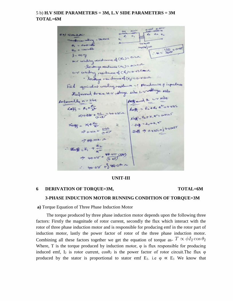
5 b) H.V SIDE PARAMETERS = 3M, L.V SIDE PARAMETERS = 3M
TOTAL=6M
UNIT-III
6 DERIVATION OF TORQUE=3M, TOTAL=6M
3-PHASE INDUCTION MOTOR RUNNING CONDITION OF TORQUE=3M
a) Torque Equation of Three Phase Induction Motor
The torque produced by three phase induction motor depends upon the following three
factors: Firstly the magnitude of rotor current, secondly the flux which interact with the
rotor of three phase induction motor and is responsible for producing emf in the rotor part of
induction motor, lastly the power factor of rotor of the three phase induction motor.
Combining all these factors together we get the equation of torque as-
Where, T is the torque produced by induction motor, φ is flux responsible for producing
induced emf, I2 is rotor current, cosθ2 is the power factor of rotor circuit.The flux φ
produced by the stator is proportional to stator emf E1. i.e φ ∝ E1 We know that
transformation ratio K is defined as the ratio of secondary voltage (rotor voltage) to that of
primary voltage (stator voltage).
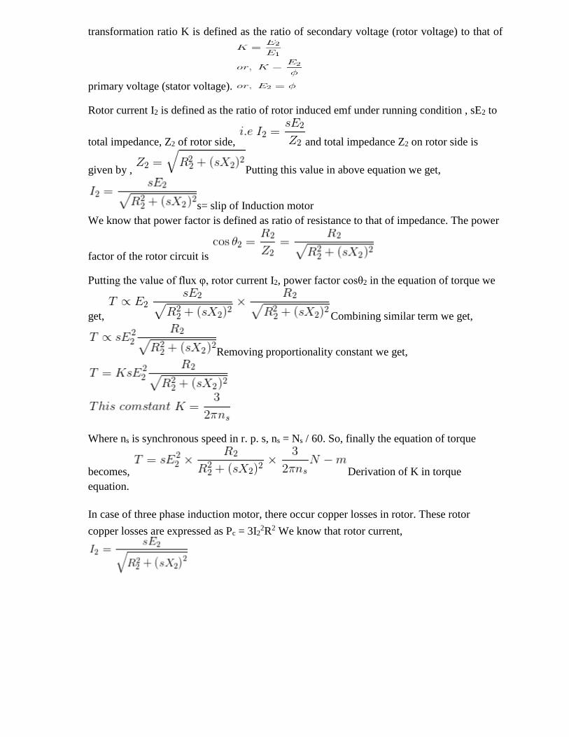
Rotor current I2 is defined as the ratio of rotor induced emf under running condition , sE2 to
total impedance, Z2 of rotor side, and total impedance Z2 on rotor side is
given by , Putting this value in above equation we get,
s= slip of Induction motor
We know that power factor is defined as ratio of resistance to that of impedance. The power
factor of the rotor circuit is
Putting the value of flux φ, rotor current I2, power factor cosθ2 in the equation of torque we
get, Combining similar term we get,
Removing proportionality constant we get,
Where ns is synchronous speed in r. p. s, ns = Ns / 60. So, finally the equation of torque
becomes, Derivation of K in torque
equation.
In case of three phase induction motor, there occur copper losses in rotor. These rotor
copper losses are expressed as Pc = 3I22R2 We know that rotor current,
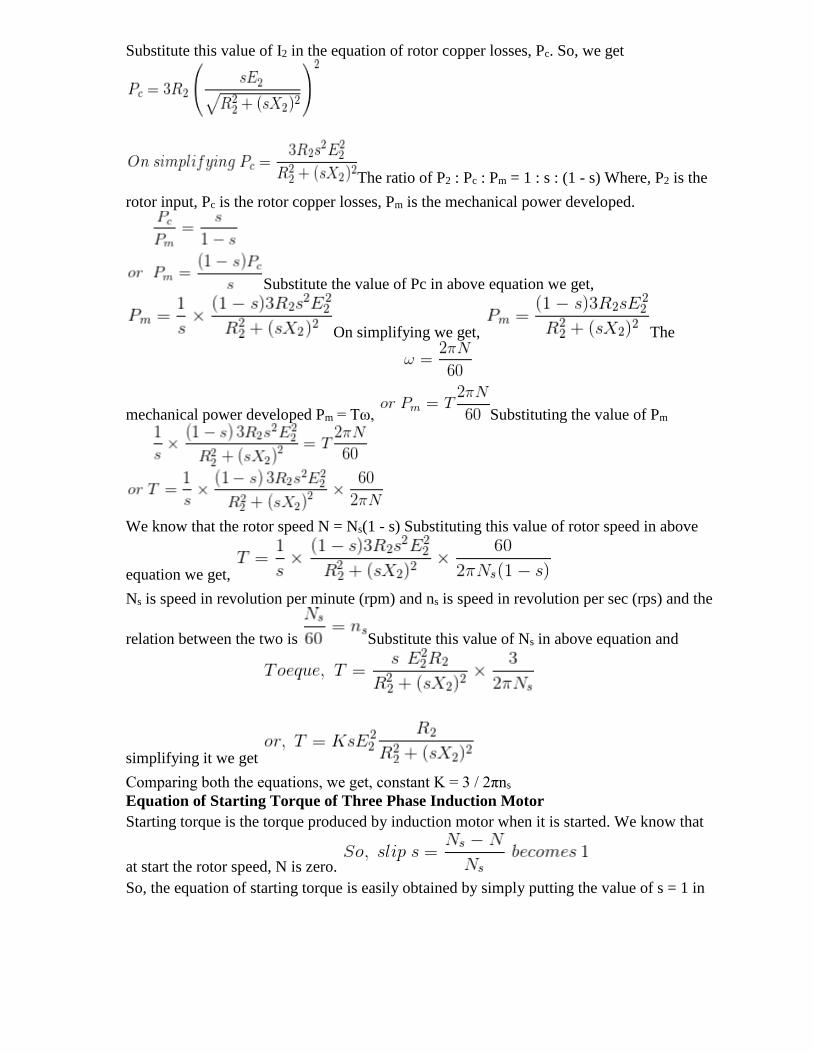
Substitute this value of I2 in the equation of rotor copper losses, Pc. So, we get
The ratio of P2 : Pc : Pm = 1 : s : (1 - s) Where, P2 is the
rotor input, Pc is the rotor copper losses, Pm is the mechanical power developed.
Substitute the value of Pc in above equation we get,
On simplifying we get, The
mechanical power developed Pm = Tω, Substituting the value of Pm
We know that the rotor speed N = Ns(1 - s) Substituting this value of rotor speed in above
equation we get,
Ns is speed in revolution per minute (rpm) and ns is speed in revolution per sec (rps) and the
relation between the two is Substitute this value of Ns in above equation and
simplifying it we get
Comparing both the equations, we get, constant K = 3 / 2πns
Equation of Starting Torque of Three Phase Induction Motor
Starting torque is the torque produced by induction motor when it is started. We know that
at start the rotor speed, N is zero.
So, the equation of starting torque is easily obtained by simply putting the value of s = 1 in
the equation of torque of the three phase induction motor,
The starting torque is also known as standstill torque.
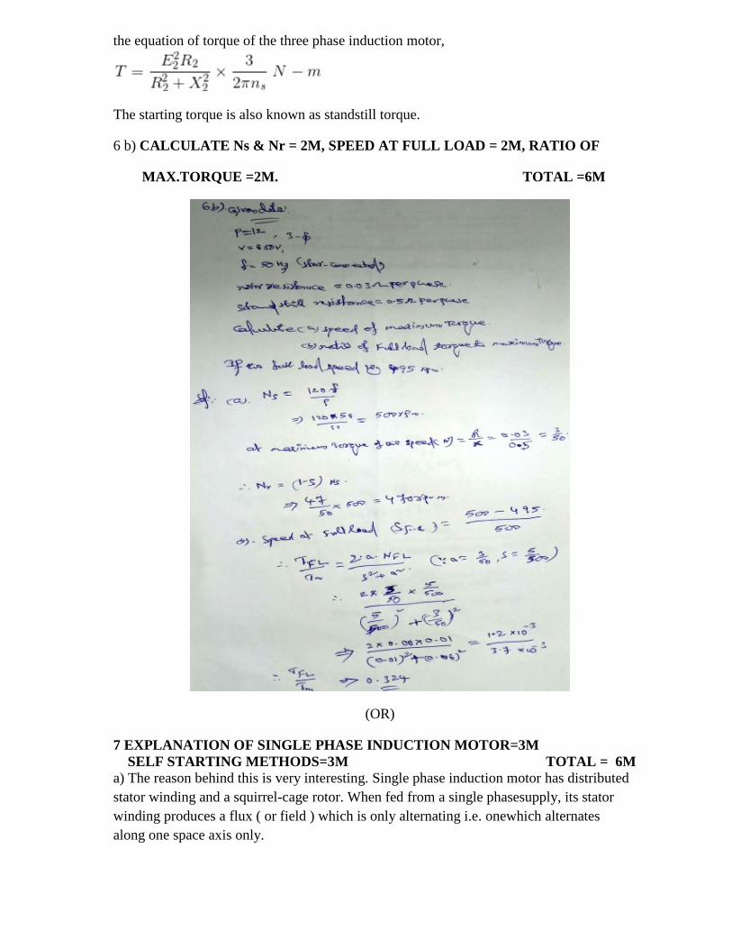
6 b) CALCULATE Ns & Nr = 2M, SPEED AT FULL LOAD = 2M, RATIO OF
MAX.TORQUE =2M. TOTAL =6M
(OR)
7 EXPLANATION OF SINGLE PHASE INDUCTION MOTOR=3M
SELF STARTING METHODS=3M TOTAL = 6M
a) The reason behind this is very interesting. Single phase induction motor has distributed
stator winding and a squirrel-cage rotor. When fed from a single phasesupply, its stator
winding produces a flux ( or field ) which is only alternating i.e. onewhich alternates
along one space axis only.
1. Single phase induction motors or asynchronous motors.
2. Single phase synchronous motors.
3. Commutator motors.
This article will provide fundamentals, description and working principle of single phase
induction motor.
Construction of Single Phase Induction Motor
Stator: As its name indicates stator is a stationary part of induction motor. A single phase ac
supply is given to the stator of single phase induction motor. Rotor: The rotor is a rotating
part of induction motor. The rotor is connected to the mechanical load through the shaft.
The rotor in single phase induction motor is of squirrel cage rotor type. The construction of
single phase induction motor is almost similar to the squirrel cage three phase motor except
that in case of asynchronous motor the stator have two windings instead of one as compare
to the single stator winding in three phase induction motor.
Stator of Single Phase Induction Motor
The stator of the single phase induction motor has laminated stamping to reduce eddy
current losses on its periphery. The slots are provided on its stamping to carry stator or main
winding. In order to reduce the hysteresis losses, stamping are made up of silicon steel.
When the stator winding is given a single phase ac supply, the magnetic field is produced
and the motor rotates at a speed slightly less than the synchronous speed Ns which is given
by
Where, f = supply voltage frequency, P = No. of poles of the motor. The construction of the
stator of asynchronous motor is similar to that of three phase induction motor except there
are two dissimilarity in the winding part of the single phase induction motor.
Firstly the single phase induction motors are mostly provided with concentric coils. As the
number of turns per coil can be easily adjusted with the help of concentric coils, the mmf
distribution is almost sinusoidal.
1. Except for shaded pole motor, the asynchronous motor has two stator windings namely
the main winding and the auxiliary winding. These two windings are placed in space
quadrature with respect to each other.
2. Rotor of Single Phase Induction Motor
The construction of the rotor of the single phase induction motor is similar to
the squirrel cage three phase induction motor. The rotor is cylindrical in shape and has slots
all over its periphery. The slots are not made parallel to each other but are bit skewed as the
skewing prevents magnetic locking of stator and rotor teeth and makes the working of
induction motor more smooth and quieter i.e less noise. The squirrel cage rotor consists of
aluminum, brass or copper bars. These aluminum or copper bars are called rotor conductors
and are placed in the slots on the periphery of the rotor. The rotor conductors are
permanently shorted by the copper or aluminum rings called the end rings. In order to
provide mechanical strength these rotor conductor are braced to the end ring and hence form
a complete closed circuit resembling like a cage and hence got its name as squirrel cage
induction motor.
Working Principle of Single Phase Induction Motor
This alternating current produces an alternating flux called main flux. This main flux
also links with the rotor conductors and hence cut the rotor conductors. According to the
Faraday’s law of electromagnetic induction, emf gets induced in the rotor. As the rotor
circuit is closed one so, the current starts flowing in the rotor. This current is called the rotor
current. This rotor current produces its own flux called rotor flux. Since this flux is
produced due to induction principle so, the motor working on this principle got its name as
induction motor. According to double field revolving theory, any alternating quantity can be
resolved into two components, each component have magnitude equal to the half of the
maximum magnitude of the alternating quantity and both these component rotates in
opposite direction to each other. For example - a flux, φ can be resolved into two
components
Each of these components rotates in opposite direction i. e if one φm / 2 is rotating in
clockwise direction then the other φm / 2 rotates in anticlockwise direction. When a single
phase ac supply is given to the stator winding of single phase induction motor, it produces
its flux of magnitude, φm. According to the double field revolving theory, this alternating
flux, φm is divided into two components of magnitude φm /2. Each of these components will
rotate in opposite direction, with the synchronous speed, Ns.
Now at starting, both the forward and backward components of flux are exactly opposite to
each other. Also both of these components of flux are equal in magnitude.
Methods for Making Single Phase Induction as Self Starting Motor
From the above topic we can easily conclude that the single phase induction motors are not
self starting because the produced stator flux is alternating in nature and at the starting the
two components of this flux cancel each other and hence there is no net torque. The solution
to this problem is that if the stator flux is made rotating type, rather than alternating type,
which rotates in one particular direction only. Then the induction motor will become self
starting. Now for producing this rotating magnetic field we require two alternating flux,
having some phase difference angle between them. Split phase induction motor,
1. Capacitor start inductor motor,
2. Capacitor start capacitor run induction motor,
3. Shaded pole induction motor.
4. Permanent split capacitor motor or single value capacitor motor.
7 b) DIFFERENCE BETWEEN SLIP RING INDUCTION MOTOR AND SLIP RING
INDUCTION MOTOR =6M
Basis For Comparison Slip Ring Induction Motor Induction Squirrel
Defintion The rotor of the motor is
Constructed as a slip ring type.
The rotor of the motor is a squirrel
cage type
Rotor Cylindrical laminated core with
parallel slots and each slot consist
one bar.
The slots of the rotor are not
parallel, but are skewed.
Construction Complicated Simple
Resistance Added external to the rotor The rotor bar is permanently
shorted at the end of the ring, thus
it is not possible to add any
external resistance.
Starter The rotor resistance starter can
be used.
Rotor resistance starter cannot be
used.
Starting Torque High Low
Brushes Present Absent
Maintenance Frequent maintenance required Less maintenance required
Copper Loss High Low
Efficieny Low High
Speed Control Possible Not Possible
Power Factor Low High
Cost Costly Cheap
Starting Current Low High
Uses Use in hoist,cranes,elevator where
high Torque is required.
Use in lathe machines, fan,
blower,Profiting machines,etc.
UNIT=IV
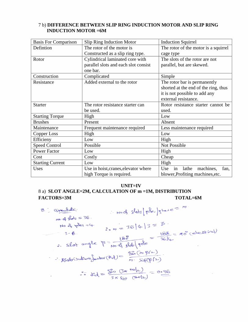
8 a) SLOT ANGLE=2M, CALCULATION OF m =1M, DISTRIBUTION
FACTORS=3M TOTAL=6M
8. WORKING PRINCIPLE OF ALTERNATOR=3M TOTAL=6M
IMPORTANCE OF THE STATOR WINDING STATIONARY ON
ALTERNATOR=3M
b) The working principle of alternator is very simple. It is just like basic principle of DC
generator. It also depends upon Faraday's law of electromagnetic induction which says the
current is induced in the conductor inside a magnetic field when there is a relative motion
between that conductor and the magnetic field.
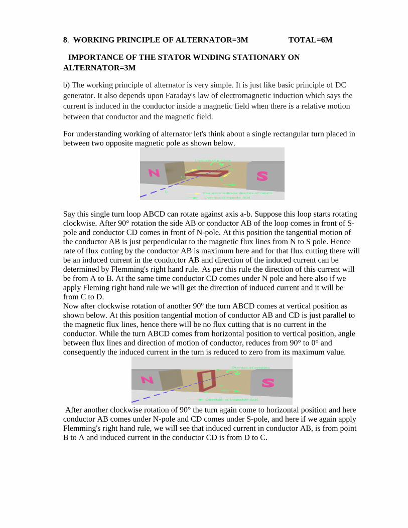
For understanding working of alternator let's think about a single rectangular turn placed in
between two opposite magnetic pole as shown below.
Say this single turn loop ABCD can rotate against axis a-b. Suppose this loop starts rotating
clockwise. After 90° rotation the side AB or conductor AB of the loop comes in front of S-
pole and conductor CD comes in front of N-pole. At this position the tangential motion of
the conductor AB is just perpendicular to the magnetic flux lines from N to S pole. Hence
rate of flux cutting by the conductor AB is maximum here and for that flux cutting there will
be an induced current in the conductor AB and direction of the induced current can be
determined by Flemming's right hand rule. As per this rule the direction of this current will
be from A to B. At the same time conductor CD comes under N pole and here also if we
apply Fleming right hand rule we will get the direction of induced current and it will be
from C to D.
Now after clockwise rotation of another 90o the turn ABCD comes at vertical position as
shown below. At this position tangential motion of conductor AB and CD is just parallel to
the magnetic flux lines, hence there will be no flux cutting that is no current in the
conductor. While the turn ABCD comes from horizontal position to vertical position, angle
between flux lines and direction of motion of conductor, reduces from 90° to 0° and
consequently the induced current in the turn is reduced to zero from its maximum value.
After another clockwise rotation of 90° the turn again come to horizontal position and here
conductor AB comes under N-pole and CD comes under S-pole, and here if we again apply
Flemming's right hand rule, we will see that induced current in conductor AB, is from point
B to A and induced current in the conductor CD is from D to C.
As at this position the turn comes at horizontal position from its vertical position, the current
in the conductors comes to its maximum value from zero. That means current is circulating
in the close turn from point B to A, from A to D, from D to C and from C to B. Just reverse
of the previous horizontal position when the current was circulating as A → B → C → D →
A.
While the turn further proceeds to its vertical position the current is again reduced to zero.
So if the turn continues to rotate the current in the turn continually alternate its direction.
During every full revolution of the turn, the current in the turn gradually reaches to its
maximum value then reduces to zero and then again it comes to its maximum value but in
opposite direction and again it comes to zero. In this way the current completes one full sine
wave form during each 360o revolution of the turn. So we have seen how an alternating
current is produced in a turn is rotated inside a magnetic field. From this, we will now come
to the actual working principle of alternator.
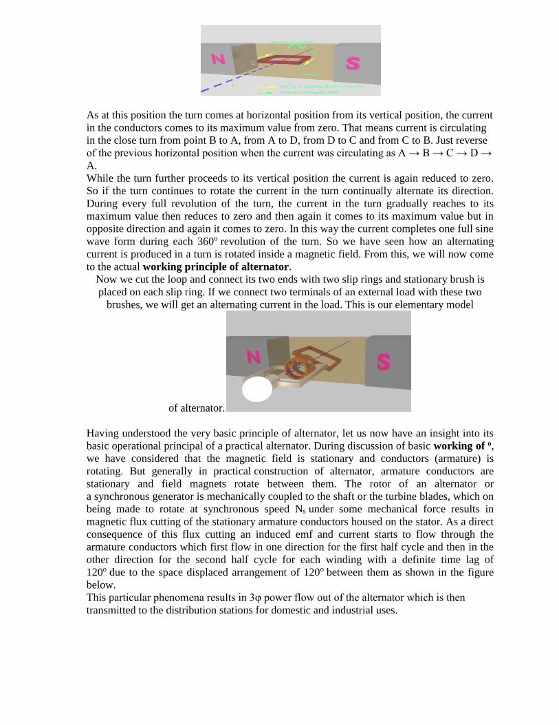
Now we cut the loop and connect its two ends with two slip rings and stationary brush is
placed on each slip ring. If we connect two terminals of an external load with these two
brushes, we will get an alternating current in the load. This is our elementary model
of alternator.
Having understood the very basic principle of alternator, let us now have an insight into its
basic operational principal of a practical alternator. During discussion of basic working of o,
we have considered that the magnetic field is stationary and conductors (armature) is
rotating. But generally in practical construction of alternator, armature conductors are
stationary and field magnets rotate between them. The rotor of an alternator or
a synchronous generator is mechanically coupled to the shaft or the turbine blades, which on
being made to rotate at synchronous speed Ns under some mechanical force results in
magnetic flux cutting of the stationary armature conductors housed on the stator. As a direct
consequence of this flux cutting an induced emf and current starts to flow through the
armature conductors which first flow in one direction for the first half cycle and then in the
other direction for the second half cycle for each winding with a definite time lag of
120o due to the space displaced arrangement of 120o between them as shown in the figure
below.
This particular phenomena results in 3φ power flow out of the alternator which is then
transmitted to the distribution stations for domestic and industrial uses.

Importance of the stator winding stationary on alternator
1) The output current can be collected directly from fixed terminals on the stator without
going through brushes.
2) It is easier to insulate stationary windings for high a.c voltages.
3) Only two slip-rings are require for d.c supply to excite the field winding on the rotor.
4) It requires less maintenance and less damage to the winding
5) The stationary armature construction causes less leakage flux, hence improves voltage
regulation.6) Armature can have more number of conductors, hence e.m.f. induced will be
more. (OR)
9 a) PHASE AND LINE VOLTAGE OF ALTERNATOR=4M,
CALCULATE Kd & Kp =2M TOTAL = 6M