SCHEDULE 1 – STATEMENT OF REQUIREMENTS
193
Coast Mountain College Student Housing Project Design-Build Agreement SCHEDULE 1 – STATEMENT OF REQUIREMENTS Coast Mountain College Student Housing Terrace, BC
Transcript of SCHEDULE 1 – STATEMENT OF REQUIREMENTS

Coast Mountain College Student Housing Project Design-Build Agreement
-
SCHEDULE 1 – STATEMENT OF REQUIREMENTSCoast Mountain College Student Housing
Terrace, BC

Coast Mountain College Student Housing Project Design-Build Agreement
1
PART 1 INTREPRETATION ......................................................................................................................... 3
1.1 GENERAL ............................................................................................................................................ 3
1.2 DEFINITIONS ....................................................................................................................................... 4
1.3 ACRONYM LIST .................................................................................................................................. 6
PART 2 GENERAL .................................................................................................................................... 8
2.1 STANDARDS ....................................................................................................................................... 8
2.2 USE OF WOOD ................................................................................................................................... 8
2.3 ROOMS & SPACES ............................................................................................................................. 8
2.4 SOURCING OF EQUIPMENT AND MATERIALS .................................................................................. 9
2.5 INDICATIVE DESIGN .......................................................................................................................... 9
PART 3 PROJECT PRINCIPLES ............................................................................................................... 10
3.1 DESIGN VALUES AND VISION ........................................................................................................ 10
3.2 DESIGN OBJECTIVES ....................................................................................................................... 10
3.3 OPERATIONAL SUSTAINABILITY AND INTEGRATION ..................................................................... 11
3.4 DESIGN SUSTAINABILITY ................................................................................................................. 12
PART 4 DESIGN PRINCIPLES ................................................................................................................. 15
4.1 BUILDING REQUIREMENTS ............................................................................................................... 15
4.2 BUILDING LOCATION, ACCESS AND SERVICING REQUIREMENTS .............................................. 15
4.3 CONSTRUCTION PHASING AND DEMOLITION .............................................................................. 16
4.4 SITE PLANNING ................................................................................................................................ 16
PART 5 BUILDING DESIGN .................................................................................................................... 21
5.1 NOT USED. ........................................................................................................................................ 21
5.2 STRUCTURAL ENGINEERING ............................................................................................................ 21
5.3 MECHANICAL ENGINEERING ......................................................................................................... 25
5.4 ELECTRICAL ENGINEERING ............................................................................................................. 27
5.5 ENERGY MODEL .............................................................................................................................. 28
PART 6 OPERATIONAL PRINCIPLES ...................................................................................................... 29
6.1 OPERATIONAL PHILOSOPHY .......................................................................................................... 29
6.2 PROJECT CAPACITY ........................................................................................................................ 29
6.3 MOVEMENT CONTROL .................................................................................................................... 29
PART 7 PROGRAM AREAS .................................................................................................................... 31
7.1 PROGRAM OVERVIEW .................................................................................................................... 31
7.2 PUBLIC SPACES ............................................................................................................................... 31
7.3 SUPPORT SPACES ............................................................................................................................ 33
7.4 TENANT COMMUNAL SPACES ........................................................................................................ 33

Coast Mountain College Student Housing Project Design-Build Agreement
2
7.5 LIVING UNITS ................................................................................................................................... 35
7.6 ADJACENCY DIAGRAM ................................................................................................................. 38
PART 8 FACILITIES CONSTRUCTION ..................................................................................................... 39
8.1 DIVISION 1 – PROCUREMENT AND CONTRACTING – NOT USED ................................................. 39
8.2 DIVISION 2 – EXISTING CONDITIONS – NOT USED ....................................................................... 39
8.3 DIVISION 3 – CONCRETE ................................................................................................................ 39
8.4 DIVISION 4 – MASONRY ................................................................................................................. 40
8.5 DIVISION 5 – METALS ...................................................................................................................... 41
8.6 DIVISION 6 – WOOD, PLASTIC AND COMPOSITES ....................................................................... 42
8.7 DIVISION 7 – THERMAL AND MOISTURE PROTECTION .................................................................. 44
8.8 DIVISION 8 – OPENINGS ................................................................................................................. 51
8.9 DIVISION 9 – FINISHES .................................................................................................................... 63
8.10 DIVISION 10 – SPECIALTIES ............................................................................................................. 74
8.11 DIVISION 11 – EQUIPMENT ............................................................................................................. 77
8.12 DIVISION 12 – FURNISHINGS .......................................................................................................... 77
8.13 DIVISION 14 – CONVEYING EQUIPMENT ...................................................................................... 79
PART 9 FACILITIES SERVICES ................................................................................................................ 80
9.1 DIVISION 21 – FIRE SUPPRESSION .................................................................................................. 80
9.2 DIVISION 22 – PLUMBING ............................................................................................................... 80
9.3 DIVISION 23 – HEATING, VENTILATION AND AIR CONDITIONING .............................................. 87
9.4 BUILDING MANAGEMENT SYSTEM ................................................................................................. 91
9.5 DIVISION 26 – ELECTRICAL ............................................................................................................. 93
9.6 DIVISION 27 – COMMUNICATIONS ............................................................................................. 107
9.7 DIVISION 28 – ELECTRICAL SAFETY & SECURITY .......................................................................... 123
PART 10 CIVIL ENGINEERING ........................................................................................................... 132
10.1 DIVISION 31 - SITE WORKS ........................................................................................................... 132
10.2 DIVISION 32 – EARTHWORKS ........................................................................................................ 135
10.3 DIVISION 33 - OFF-SITE IMPROVEMENTS ..................................................................................... 135
10.4 DIVISION 34 – UTILITIES ................................................................................................................. 135
APPENDIX 1A – Room Data SheetsAPPENDIX 1B – Acoustical Chart APPENDIX 1C – Systems Responsibility MatrixAPPENDIX 1D – Equipment List

Coast Mountain College Student Housing Project Design-Build Agreement
3
Part 1 INTREPRETATION
1.1 General
The documents forming this Schedule are intended to be complementary and interpreted in harmony so as to avoid conflict with words and phrases and interpreted in a manner consistent with Good Industry Practice.
This Schedule 1 is written as an output specification and defines what the Design-Builder will achieve in the Design and Construction. Except where otherwise expressly stated within this Schedule 1, the Design-Builder will carry out the Design and Construction as required and contemplated by each provision of this Schedule 1, whether or not the provision is written as an obligation of the Design-Builder or stated in the imperative form.
Where “cost effective”, “appropriate”, “sufficient”, “minimize” and related and similar terms are used in this Schedule 1, they are to be construed and interpreted in terms of whether they are cost effective, appropriate, sufficient or minimize, from the perspective of a prudent public owner of a post-secondary institution that is designed and constructed for the public owner through a design-build model, where the prudent public owner balances capital costs against maintenance, operations, security, reliability and all of the costs over the life of that Facility.
The Design-Builder may, at any time, request that the Owner accept an equivalent by submitting to the Owner for review under the Review Procedure, details of the proposed equivalent, together with such supporting documentation and information as the Owner’s Representative may require. Acceptance of an equivalent may in the discretion of the Owner’s Representative be withheld or may be granted subject to such conditions as the Owner, in its discretion, considers appropriate.

Coast Mountain College Student Housing Project Design-Build Agreement
4
1.2 Definitions
Note that all capitalized room names used in this Schedule 1 have the meaning as identified in the Functional Space Requirements, found in this Schedule 1 under Part 7.
“Accessible Living Unit” means a Living Unit that accommodates a disabled Occupant.
“Authority” or “Authority Having Jurisdiction” means a person who has the delegated authority to determine, mandate, and enforce code requirements established by jurisdictional governing bodies.
“Bedroom” means the room in which there is a bed, wardrobe and desk.
“Building” means the new student housing building.
“Building Systems” means the interacting or interdependent mechanical, electrical and other system components that comprise a building such as structural, roofing, side wall, plumbing, HVAC, water, sanitary sewer and electrical, communication and security systems.
“Building Gross Square Meters” or “BGSM” means the sum of all Building floor areas measured to the outside face of exterior walls for all stories or areas having floor surfaces within a building. The BGSM includes component gross area, general circulation, mechanical and electrical space and exterior walls.
“Communications” means any transmission, emission, and reception of signs, signals, writings, images, and sounds; that is, information of any nature by using copper cable, radio, optical, or other electromagnetic systems.
“Communications Rooms” means any of the following room types: Entrance Building Room (EF), Main Telecommunication Room (MTR), and Telecommunication Room (TR).
“Crime Prevention Through Environmental Design” or “CPTED” means a multi-disciplinary approach to deterring undesirable and criminal activity and behavior through environmental design;
“Data Drops” means the complete Category 6A structured cabling connection or permanent link between the RJ45 connector in a telecommunication outlet and the horizontal cross connections in the Communications Room.
“Design Life” means the period of time for which a component, device or system is expected to function within its specified parameters without major repairs;
“Functional Space Requirements” means the lists, found in this Schedule 1 under Part 7, of required spaces and associated floor areas to be included in the design of the Building.
“Good Industry Practice” mean the standards, practices, methods and procedures to a good professional and commercial standard, conforming to Laws and exercising the degree of skill, care and diligence. Prudence and foresight which would reasonably and ordinarily be expected from a qualified, skills and experiences person engaged in a similar type of undertaking under the same or similar circumstances.
“Hoteling Unit” means a Living Unit for registered guests.
“Indicative Design” has the meaning as relayed in Schedule 1 – Section 2.5.3.

Coast Mountain College Student Housing Project Design-Build Agreement
5
“Industry Standard” means generally accepted technical requirements, methods, processes and practices followed by members of an industry.
“Living Unit” means an assembly of Bedroom(s) and associated support spaces with a single point of entry/exit.
“Longhouse” means the existing building as identified in Schedule 10 - Site Plan.
“Malicious Damage” means damage to, or destruction of, the Building or any part thereof, which requires repair and which is caused by malicious, intentional, willful, negligent or careless conduct.
“Modular” when used to describe a component of the Work, means that such component is standardized and fabricated and assembled off-Site such that it is structurally complete, inclusive of installed electrical and mechanical systems, and when installed on Site will only require final interconnections to be made to integrate such component with other components of the Work.
“Natural Light” means direct natural light sourced from the sun.
“Net Area” or “Net Square Meters” or “NSM” means the horizontal area of space assignable to a specific function. The Net Area, Net Square Meters and NSM of space is measured to the inside face of wall surfaces.
“Occupant” means any Staff, visitor, contractor, service provider, student or other person who is within the confines of the Building.
“Public Spaces” means the spaces accessible to the public.
“Quad Living Unit” means a Living Unit with four Bedrooms.
“RA” means an employee of the Owner who resides in the Building for the purposes of assisting Tenants.
“Single Living Unit” means a Living Unit having one Bedroom.
“Staff” means employees of the Owner.
“Structure” means any constructed part of the Building.
“Support Spaces” means the spaces accessible only to authorized persons.
“Telecommunications” means Communications.
“Telecommunications Outlet” means an assembly of components consisting of one or more connectors and a faceplate or housing.
“Tenant Communal Spaces” means the spaces only accessible to Tenants and their escorted guests.
“Tenants” means students, including RAs, and guests who are registered to live in the Building.
“Triple Living Unit” means a Living Unit with three Bedrooms.

Coast Mountain College Student Housing Project Design-Build Agreement
6
1.3 Acronym List
AAMA - American Architectural Manufacturers Association
AATC – American Association of Textiles Chemists and Colourists
AAS – Aluminum Association Standards
AC – Alternating Current
ACS – Access Control System
ACH – Architectural Hardware Consultant
AFCI – Arc Fault Circuit Interrupter
AFF – Above Finished Floor
AFUE - Annual Fuel Utilization Efficiency
ANSI - American National Standards Institute
ASHRAE - American Society of Heating, Refrigerating and Air-conditioning Engineers
ASIS - American Society for Industrial Security
ASME - American Society of Mechanical Engineers
ASPE - American Society of Plumbing Engineers
ASTM - American Society for Testing and Materials
ATS – Auto Transfer Switch
AV / IT – Audio Visual / Information Technology
AWCC – Association of Wall and Ceiling Contactor’s
AWMAC – Architectural Woodworker Manufacturers Association of Canada
AWWA – American Water Works Association
BCBC – British Columbia Building Code
BCFCA – British Columbia Floor Covering Association
BCICA - British Columbia Insulation Contractors Association
BHMA – Builders Hardware Manufacturing Association
BMS - Building Management System
Bx – Armored Cable
CATV – Community Access Television
CCI – Canadian Carpet Institute
CEC – Canadian Electrical Code
CFC – Chlorofluorocarbon
CGA - Compressed Gas Association
CGSB – Canadian General Standards Board
CISCA - Ceiling Interior Systems Construction Association
CMCA – Canadian Masonry Contractors Association
CPTED - Crime Prevention Through Environmental Design
CRI – Canadian Rug Institute
CSA - Canadian Standards Association
CSDFMA – Canadian Steel Door Frame and Manufacturers Association
CSSBI – Canadian Sheet Steel Building Institute Standards
DBA – Design Build Agreement
DC – Direct Current
DDC – Direct Digital Control
DHCP – Dynamic Host Configuration Protocol
DHI - Door and Hardware Institute of Canada
DMVS – Digital Video Management System
DPDT – Double Pole Double Throw
ECABC – Electrical Contractors Association of British Columbia
EF - Entrance Building Room
EIA – Electronics Industry Association
EMT – Electric Metallic Tubing
EPA – Environmental Protection Agency
ESCS - Electronic Security and Communication System
ESS - Electronic Safety and Security Systems
FA – Fire Alarm
FACP – Fire Alarm Control Panel
FM – Factory Mutual
FOV – Field of View
FPS – Frames per second
GB – Gigabyte
GCA – Glazing Contractors Association
GPON – Gigabit Passive Optical Network
GFCI – Ground Fault Circuit Interrupter
GUI – Graphical User Interface
GWB – Gypsum Wall Board
HCFC - Hydrochlorofluorocarbon
HOA – Hand-Off-Auto
HP – Horsepower
HVAC - Heating, Ventilating and Air-Conditioning
IAQ - Interior Air Quality
ICC – International Code Council
ID - Identification
IEEE - Institute of Electrical and Electronic Engineers
IGMAC - Insulating Glass Manufacturers Association of Canada
IIC - Impact Insulation Class
IP – Internet Protocol

Coast Mountain College Student Housing Project Design-Build Agreement
7
IT – Information Technology
IMIT – Information Management Information Technology
IS – Intercommunications System
ISO – International Organization for Standardization
IT – Information Technology
LAN – Local Area Network
LCD – Liquid Crystal Display
LED – Light Emitting Diode
LEED® v4 -Leadership in Energy and Environmental Design Version 4.0
LID – Low Impact Design
MERV – Minimum Efficiency Reporting Value
MPI – Master Painters Institute
MTR - Main Telecommunication Room
NBCC – National Building Code of Canada
NC – Noise Criterion
NEBS – Network Equipment Building Systems
NEMA - National Electrical Manufacturers Association
NFPA - National Fire Protection Association
NRC - National Research Council
NSM – Net Square Metres
NTP – Network Time Protocol
NVR – Network Video Recorder
OSDP – Open Supervised Device Protocol
PA – Paging Announcement (Paging System)
PoE – Power Over Ethernet
PSI – Pounds per Square Inch
PTZ – Pan Tilt Zoom
PVC – Polyvinyl Chloride
RA – Resident Advisor
RCDD – Registered Communications Distribution Designer
RCABC – Roofing Contractors Association of British Columbia
RF – Radio Frequency
RU – Underwriters Laboratory certified products intended to be used inside other products
SER – Structural Engineer of Record
SHGC – Solar Heat Gain Coefficient
SIP – Session Initiated Protocol
SMACNA – Sheet Metal and Air Conditioning Contractors National Association
STC – Sound Transmission Class
TCP – Transmission Control Protocol
THD - Total Harmonic Distortion
TIA – Telecommunications Industry Association
TO – Telecommunications Outlet
TR - Telecommunication Room
TRA – Threat Risk Assessment
TTMAC – Terrazzo and Tile Manufacturers Association of Canada
TV - Television
TVOC – Total Volatile Organic Compounds
ULC - Underwriters’ Laboratories of Canada
UL – Underwriters Laboratory
UPS – Uninterruptible Power Supply
USGBC – United Stated Green Building Code
UV – Ultra Violet
V – Volt
VAR – Volt Ampere Reactive power
VFD - Variable Frequency Drive
VLAN – Virtual Local Area Network
VOC – Volatile Organic Compounds
VoIP – Voice Over Internet Protocol
VSS – Video Surveillance Systems
WAP – Wireless Access Point
WH – Wamock Hersey
WLAN – Wireless Local Area Network

Coast Mountain College Student Housing Project Design-Build Agreement
8
Part 2 GENERAL
2.1 Standards
The Design-Builder will complete the Design and Construction:
2.1.1.1 in accordance with all Standards;
2.1.1.2 in accordance with the requirements of this Agreement, including this Schedule 1;
2.1.1.3 in accordance with all applicable codes, standards, specifications and guidelines published by relevant standards organizations;
2.1.1.4 having regard for the concerns, needs and interests of:
(a) the Owner;
(b) all persons who will be Building users; and
(c) the City of Terrace;
2.1.1.5 in accordance with Good Industry Practice; and
2.1.1.6 to the same standard that an experienced, prudent and knowledgeable long term owner of a high quality student housing building in North America would employ.
If more than one of the applicable codes, standards, specifications and guidelines published by relevant standards organizations applies to the Design or Construction then the most stringent code, standard, specification or guideline will be deemed to apply, with the intent that the code, standard, specification or guideline that would produce the highest level of quality, safety, security, reliability, durability, performance and service will govern.
2.2 Use of Wood
As contemplated by the Wood First Act (British Columbia), the Design-Builder will incorporate wood products into the design of the Building to the extent that the use of wood products is consistent with the requirements of this Schedule 1 and the BC Building Code.
The Design-Builder will use of wood as a featured material for both the interior and exterior of the Building which will include both structural and finishing aspects.
The Building will be constructed using wood Modular construction, following the Wood First Act (British Columbia) which facilitates a culture of wood use as the primary building material in all new provincially funded buildings, in a manner consistent with current building regulations.
2.3 Rooms & Spaces
The Design-Builder will design and construct the Building:
2.3.1.1 so that it accommodates all of the spaces, activities, functions, design features and adjacencies described in Part 7 of this Schedule 1;
2.3.1.2 in accordance with the requirements of this Schedule 1 subject to any adjustments or refinements made pursuant to the Review Procedure and;
2.3.1.3 if the NSM for any room or space is proposed to be more than 5% smaller than the required NSM. The Design-Builder will submit the proposed variance to the Owner for review, together with the rationale for the proposed variance and evidence to

Coast Mountain College Student Housing Project Design-Build Agreement
9
demonstrate to the Owner’s satisfaction that affected rooms retain their functionality. If, as determined in the Owner’s discretion, the room or space does not meet the required functionality, the full NSM will be provided as stated in the Functional Space Requirements.
(a) rooms must allow for furniture to fit and function.
No reduction in the required NSM for any room or space will be permitted except as described in Section 2.3.1.3 of this Schedule 1.
Notwithstanding anything in the Functional Space Requirements, the Design-Builder will design and construct the Building to include all rooms and spaces as required to comply with the terms of this Agreement, including sufficient rooms and spaces as necessary (including electrical, mechanical and IT service rooms) for the proper operation and maintenance of the Building.
2.4 Sourcing of Equipment and Materials
Unless this Schedule 1 expressly allocates to the Owner a specific responsibility in respect of the supply and/or installation of products, materials, equipment, furniture or furnishings, the Design-Builder shall be responsible to supply and install any and all products, equipment, furniture and furnishings that are specified to be provided by these Statement of Requirements, including as described in Appendix 1C – Systems Responsibility Matrix and Appendix 1D – Equipment List.
All systems, equipment, products, components, and other materials incorporated into the Building will be new, unused and of a type and quality intended for use in a permanent Building.
Notwithstanding Section 2.4.2. of this Schedule 1, reclaimed wood may be used at the discretion of the Owner.
2.5 Indicative Design
An Indicative Design is provided in the Disclosed Data.
The Design-Builder may refer to the Indicative Design in the development of the Design, but the Owner makes no representation or warranty as to the reliability, accuracy, completeness or correctness of any aspect of the Indicative Design.
The Indicative Design is relayed as a guide to demonstrate the required functional and operational objectives for the Building and is not intended to illustrate a singular design solution.
The Design-Builder will be completely responsible for all aspects of the design and construction of the Project whether or not it uses all or any part of the Indicative Design.
The Design-Builder will independently verify the reliability, accuracy, completeness and correctness of any information contained in or inferred from the Indicative Design if the Design-Builder uses any such information in the Design.

Coast Mountain College Student Housing Project Design-Build Agreement
10
Part 3 PROJECT PRINCIPLES
3.1 Design Values and Vision
Coast Mountain College serves as an academic hub and an important regional training centre for the North Coast of British Columbia, including 7 First Nations: Haida, Tsimshian, Haisla, Nisga’a, Gitxsan, Wet’suwet’en and Tahltan.
The student experience, primarily that of First Nations students is of utmost importance, providing a familiar and comfortable environment.
The Project is to be purposefully designed for Coast Mountain College students and reflect a uniquely North Coast design and architectural image, combining traditional First Nations architecture, with the contemporary aesthetic in current designs of the most recent work on Campus.
3.1.3.1 Student housing provides greater capacity for First Nations and non-First Nations learners to access education in the region, thus increasing the number of post-secondary graduates and skilled workers available to support the local economy.
3.1.3.2 The Building will also accommodate students from a world-wide range of other cultures. It is important that the design of the Building serve as a means to encourage a mixing of all Tenants in their daily activities to learn about each other and their unique perspectives.
3.1.3.3 The design and configuration of individual suites and Tenant Communal Spaces are to be arranged to support cross-cultural collaboration and a communal atmosphere by encouraging students to spend less time in their units and more in shared areas.
First Nations culture is a key aspect to Coast Mountain College and plays an important role in their drive to be the institution of choice for experiential, place-based learning. The Building will be designed to reflect the First Nations culture in the region, and to support First Nations learners in a manner intended to establish a new standard for future buildings.
The Building is to be complimentary to, but not a direct reflection of both the existing Longhouse and House of Cedar (trades) building.
3.2 Design Objectives
Design Introduction
3.2.1.1 Design and construct the Building to meet the following requirements:
(a) Foster an environment that reflects, supports and embraces First Nations culture and practices for Coast Mountain College students and the community. This will be reflected in placement of programmed elements, the interior and exterior design and material choices throughout the building.
(b) Use real wood products rather than manufactured copies from other substances. Use rough-hewn structural elements, traditionally-finished cedar panels and other natural wood elements, unless otherwise specified in the RDS. Cedar is the preferred wood material.
(c) Be positioned and oriented in a manner that respects, connects to and enhances the Campus context by exposing the Longhouse to view from across Campus and connecting to existing pedestrian circulation.
(d) Provide a high-quality, safe, comfortable and secure environment respecting and responding to the cultural diversity of the Coast Mountain College.

Coast Mountain College Student Housing Project Design-Build Agreement
11
(e) Meet the Owner’s functional, aesthetic and performance requirements, from both a quantitative and qualitative perspective. The Building will incorporate appropriate, durable and flexible architectural, structural, mechanical, electrical and technological systems designs.
(f) Respond to Site characteristics and opportunities as well as climatic conditions and maximize provisions for environmental sustainability.
(g) Use a process that ensures that the Owner is meaningfully and effectively engaged with modifications as required in the finalization of the design.
(h) Provide for integrated and adaptive technology including high-performing, upgradable and proven technology for telecommunications infrastructure, wireless access, audio visual infrastructure and security infrastructure.
(i) Create a comfortable environment in all areas of the Building including provision of: quality thermal and ventilation conditions, safe materials and acoustic and vibration separation between various functions, supported by ergonomic furnishings.
(j) Design-Builder to provide designated wall areas for the incorporation of First Nations art to be provided by the Owner.
(k) The provision of effective, high-velocity mechanical ventilation in:
(i) All Tenant Kitchens; and
(ii) The Cultural Space where smudging may occur.
3.3 Operational Sustainability and Integration
Design and construct the Building to minimize disruption of existing Campus electrical and mechanical services.
The Building will be designed with infrastructure that allows for upgrading and flexibility in technology and technological progression.
Design and construct the Building to achieve a Design Life of at least 40 years from Substantial Completion. Individual components and systems of the Building will have a Design Life consistent with Good Industry Practice or such longer period as may be expressly specified in Table 3.3.3-1 - Design Life of this Schedule 1.
Table 3.3.3-1 - Design Life
Component Design Life (years)Building Structure 40 Hardscape Finishes 20+ Air Conditioners
Commercial through-the wall 15 Water-cooled package 15
Heat PumpsCommercial air-to-air 15 Commercial water-to-air 15
Roof-top air conditioners 15 Boilers 25 Fans
Centrifugal 25 Axial 20

Coast Mountain College Student Housing Project Design-Build Agreement
12
Ventilating Roof-Mounted 20 Reciprocating chillers 20 Air-cooled condensers 20
3.4 Design Sustainability
Passive Design
3.4.1.1 Utilize passive design principles to guide the design of the Building to optimize Occupant health and comfort and minimize energy use by minimizing reliance on mechanical and electrical systems. Optimize the Building orientation, form and thermal performance of Building elements (including architectural, structural, envelope and passive mechanical) for interaction with the local microclimate.
3.4.1.2 Combine the following passive building design strategies to ensure inherent synergies produce optimal comfort and building energy performance:
(a) Site orientation of the Building:
(i) design the Building facades so that they will take advantage of passive solar heating during colder months and reduce overheating in warmer / hotter months; and
(ii) design the facades of the Building to minimize unwanted heat loss.
(b) Interior Space Planning:
(i) optimize Functional Space Requirements with the Building’s orientation and massing to decrease energy use and increase thermal comfort; and
(ii) place Building functions with particular thermal requirements in areas of the Building that can provide those conditions with minimal mechanical intervention.
(c) Passive Heating:
(i) harness solar radiation and capture internal heat gains to add free thermal energy to the Building; and
(ii) provide passive solar heating strategies and a well-insulated envelope to minimize energy losses and harness and store solar gains.
(d) Passive Ventilation:
(i) incorporate passive ventilation strategies into the design of the Building to take advantage of naturally occurring airflow patterns around and in the Building to introduce outdoor air into the interior spaces.
(ii) incorporate induced ventilation strategies by means of high spaces, such as atria, stacks and wind towers, to provide adequate ventilation by passive means.
(e) Passive Cooling:
(i) use passive cooling strategies to prevent the Buildings from overheating by blocking solar gains and removing internal heat gains; and

Coast Mountain College Student Housing Project Design-Build Agreement
13
(ii) couple passive cooling strategies with passive ventilation strategies, such that the cooling function will be achieved by increased passive ventilation airflow rates during periods when the outdoor air temperature is low enough to flush heat from the Building.
(f) Natural Light:
(i) reduce the need for artificial electric lighting by distribution of diffused Natural Light throughout the Building’s interiors.
Landscape
3.4.2.1 Use mature, native vegetation and landscape features to reduce ambient temperatures, reduce the heat island effect of the Building, protect the Building from sun, wind and precipitation, and reduce solar intensity.
Buffer Spaces
3.4.3.1 Buffer spaces are to be located directly along-side the Building perimeter and will be used to improve Building energy performance by widening the range of outdoor temperatures in which thermal comfort can be maintained in the Building with low mechanical energy consumption.
3.4.3.2 Integrate occupied buffer spaces as transition spaces to capitalize on the wider thermal comfort range in spaces like corridors and entryways, as opposed to other, more tightly conditioned spaces.
3.4.3.3 Incorporate a main Entry Vestibule into the Building design, maintained at wider thermal comfort ranges, to help reduce the mechanical system energy consumption by limiting the loss of heated air during winter and cooled air during summer.
Windows
3.4.4.1 Design windows to achieve the optimal combination of heating, cooling and use of Natural Light in conjunction with security requirements.
3.4.4.2 Provide easily accessible means for window washing and maintenance.
3.4.4.3 Provide operable windows in every Bedroom and the Large Project Rooms.
3.4.4.4 Triple-paned windows are to be used if required for Step 4 of the BC Energy Code requirements.
3.4.4.5 Glazing is to be selected to maximize daylighting while minimizing solar heat gains (SHGC) unless this is proven to assist in meeting energy reduction targets.
Solar Shading
3.4.5.1 Use external shading devices to intercept, absorb and/or reflect solar radiation before it reaches the exterior glazed surface of the building envelope as required to optimize energy use and passive solar gains.
3.4.5.2 Design shading devices to their particular facade orientation and to be able to provide the appropriate performance to meet both winter heating and summer shading/cooling requirements.
Air and Moisture Tightness
3.4.6.1 Use an air- and moisture-tight Building envelope to eliminate unwanted air and moisture infiltration.

Coast Mountain College Student Housing Project Design-Build Agreement
14
3.4.6.2 Design the Building to optimize air tightness and minimize air infiltration as required for Step 4 of the BC Energy Code requirements.
Thermal Bridging
3.4.7.1 Design and detail façade connections, window and door perimeters, roof and corner joints, foundations and walkway/building slabs to minimize thermal bridging.
3.4.7.2 Exterior envelope penetrations are to be minimized wherever possible.

Coast Mountain College Student Housing Project Design-Build Agreement
15
Part 4 DESIGN PRINCIPLES
4.1 Building Requirements
The Project is intended to conform to all City of Terrace bylaws for the College and as a result no re-zoning or development variance is anticipated. Should this condition be altered as a result of the Design-Builder’s Design or methods of Construction, any and all required variances will be the sole responsibility of the Design-Builder at no cost or expense to the Owner and the Design-Builder will not be entitled to, nor with the Design-Build make a claim for, a Change in respect of such variances.
The Building will be multi-story, composed of multiple wings of Living Units of modular wood construction, joined together by a central community space which can be of non-modular design and construction.
In addition to serving daily needs of ground floor Tenants, the ground floor space of the connecting structure will be supportive of larger gatherings. The upper portions will provide visual connections between all floor levels and serve as lounge and dining areas for each floor. This connecting section will utilize significantly glazed areas to internally allow views to the surrounding mountains and, at night, serve as a beacon of activity when viewed from outside.
The design of the Building is to provide an exterior appearance of in-place construction, with no visible evidence that the Modular wood portions of the Building were substantially constructed off-Site by way of continuous cladding over joints.
Where a sloped roof is provided, overhangs will be sufficient to reduce snow and rainfall from impacting Building facades. The slope direction of the roof and the potential for snow fall is to be taken into account in the design such that surrounding pedestrian pathways will not be impacted by snow falling from the roof.
CPTED principles are to be used throughout the site and Building design to reinforce safety and security of students, staff and buildings. This includes the elimination of hiding spots, high plantings, planning direct line of site views from the Admin Office.
4.2 Building Location, Access and Servicing Requirements
A new road providing vehicular access to the Building from McConnell Avenue will be provided to allow vehicles to reach the front of the Building and then exit at the same point of entry.
The end of the new road will provide a turning circle for suitable for box trucks up to 30’ in length to return to McConnell Avenue without the need to reverse direction. In the middle of the paved turnaround will be a landscaped island with a secured outdoor 120V electrical power outlet.
Vehicular access will accommodate movements of municipal transfer vehicles accessing and removing refuse. The location of where the transfer of refuse occurs will have a concrete pad of 1.5m x 2.0m and be screened from public view.
Provide new sidewalks connecting all Building entrances and exits to existing pedestrian connections in proximity to the Building. Sidewalks along the new road connecting the Building to McConnell Avenue are not required.
Provide two accessible parking stalls in close proximity to the entry of the Building.
4.2.5.1 Vehicular Network
(a) Provide sufficient access to the Building by emergency vehicles.

Coast Mountain College Student Housing Project Design-Build Agreement
16
(b) Integrate natural surface drainage patterns, avoiding traditional curbs and gutters.
(c) Minimize vehicular and pedestrian conflict throughout the Site.
4.2.5.2 Bicycle Racks
(a) Provide secure outdoor bicycle rack(s) located adjacent to the main entrance of the Building and under cover. Rack(s) are to be anchored permanently to a concrete slab. Rack(s) are to accommodate a minimum of 6 bicycles.
4.3 Construction Phasing and Demolition
The Design-Builder will carry out the Construction in accordance with a Project Management Plan.
The Project Management Plan submitted by the Design-Builder will address all minimum requirements outlined in Section 5.3.3. of this Schedule 1 and in Section 24.1 of the Design-Build Agreement.
The final demolition plan will be proposed by the Design-Builder and will be subject to review and approval by the Owner based upon the following:
4.3.3.1 Phase 1 - Site preparation. The site will be prepared for the construction of the Building. The Kalum Lake building has the option of being demolished prior to construction of the Building.
4.3.3.2 Phase 2 – Construction of the Building with a Target Completion Date of no later than August 6, 2021.
4.3.3.3 Not used.
Refer to Section 9.5.4 for Electrical Demolition & Re-Servicing.
4.4 Site Planning
Site Context
4.4.1.1 The Design-Builder will prepare and submit a Site Plan design concept to the Owner for review within 30 days after the Effective Date.
4.4.1.2 The site planning will:
(a) allow for sightlines to the Longhouse from the main entry plaza of the Building;
(b) incorporate aspects of First Nations culture;
(c) integrate with existing pedestrian connections;
(d) take into account key aspects of the Campus master Plan;
(e) account for the existing Site topography and promote accessible circulation; and
(f) provide for effective vehicular servicing access to and from McConnell Avenue, including provisions for snow clearing.
Open Space Design
4.4.2.1 Requirements
(a) All adjacent open spaces to the Building will be designed to strengthen a calm, safe and secure sense of place.

Coast Mountain College Student Housing Project Design-Build Agreement
17
(b) Open spaces will complement the scale, form, finishes, and programming of the adjacent Building.
(c) The Design-Builder will design human-scale open spaces that foster positive, daily interactions between users and the natural environment and that:
(i) provide opportunity for First Nations cultural activities;
(ii) provide areas that encourage user reflection and repose;
(iii) respond to microclimatic Site conditions with opportunities to be in sun or shade; and
(iv) offer flexibility in use.
(d) Provide weather and climate rated power and water supply in close proximity to all exterior gathering areas.
4.4.2.2 Open Space Program
(a) Demolition Area
(i) Demolition area includes any land altered during the demolition of Kalum Lake building and any adjacent infrastructure within the Site A boundary as shown on the Site Plan.
(ii) New, low-maintenance planting will be designed to visually integrate with existing landscaping features and show no indication of the demolition area.
(b) Outdoor Patio
(i) Provide an Outdoor Patio that is directly adjacent to the Student Lobby. The Outdoor Patio area will be designed to:
1. accommodate a minimum of 30 people at tables and chairs;
2. maximize solar exposure; and
3. offer mountain views.
4.4.2.3 Site Features to Preserve
(a) The Design-Builder will provide a rationale that justifies tree removal for acceptance by the Owner.
4.4.2.4 Low Impact Design (LID) Strategy
(a) The Design-Builder will prepare and submit to the Owner a stormwater management plan to:
(i) replicate as closely as possible, pre-development drainage patterns; and
(ii) implement LID strategies to manage all stormwater on-site. LID strategies include, but are not limited to:
1. harvesting rainwater from roofs, for reuse;
2. specifying permeable surfacing to infiltrate water into underlying soils;

Coast Mountain College Student Housing Project Design-Build Agreement
18
3. directing surface runoff to vegetated swales, rain gardens, and absorbent landscapes;
4. selecting drought tolerant and native plants;
5. using tree canopy in areas with hardscape, to increase evapotranspiration rate of water and reduce surface runoff, and
6. making best management practices visible as educational opportunity.
4.4.2.5 Pedestrian Walkways
(a) Provide legible, safe, and intuitive pedestrian walkways that connect the Buildingto the existing walkway network.
(b) Pedestrian walkways will capitalize on Site topography and scenic views available.
(c) Walkways are to be continuous from Building entry, around any new roadways or roundabouts and connect to existing walkways on Campus at the Jackpine and Spruce buildings.
(d) Crosswalks are to be provided if walkway is to cross new roadworks or roundabouts.
(e) All walkways will have positive drainage to direct rainwater to infiltration areas.
(f) Walkways will allow for safe wheelchair passage, and be universally accessible.
(g) Surfacing at walkways will:
(i) accommodate programed functions and intended use;
(ii) provide comfort, durability, longevity, adaptability; and
(iii) allow for ease of maintenance.
4.4.2.6 Building Entrances and Exits
(a) The main Entry Vestibule will be easily identifiable and provide a welcoming impression.
(b) Open space at all Building entrances and exits will be legible, identifiable, and relate to pedestrian and vehicular routes, as applicable.
(c) The main Building floor level is to be at least 150mm above average grade and no more than 300mm. All entrances and exits are to be step-free and sloped to meet accessibility guidelines.
(d) No access ramps or grades are to be greater than 1:20.
(e) All Building entrances and exits are to be provided cover to protect from rain and snowfall.
(f) All access points to the Building will be weather protected by means of an overhang or canopy above. The main entrance will have an exterior weather protected zone in front of the doors of a minimum of 10 square meters.
(g) The Entry Vestibule canopy will be at least 3.5 meters clear to the underside of any surface.

Coast Mountain College Student Housing Project Design-Build Agreement
19
(h) Canopies at other Building access points will be no less than 3 meters clear to the underside of any surface.
(i) Main sidewalks to Building entrances, exits, storage access and waste receptacles, ramps and other surfaces used to access the Building are to be no less than 2.44m clear in width and 2.15m clear in height in order to remove snow mechanically utilizing the Owner’s snow clearing vehicle.
(j) Lighting will be provided near Building entrances and exits.
(k) Interior and exterior finishes will complement one another, unifying the transition between open space design and the built environment.
4.4.2.7 Exterior Lighting
(a) Exterior lighting fixtures and luminaires will be selected to:
(i) provide visual comfort and quality light to open spaces;
(ii) provide for a safe and secure Campus; and
(iii) display a finish, scale and aesthetic that relates to the Building aesthetic.
(b) Lighting at roadways, walkways, and parking areas will provide safe vehicle and pedestrian movement with respect to collisions, personal safety, and Building access and egress.
4.4.2.8 Exterior Signage
(a) Provide exterior signage that clearly identifies the Building (name to be provided by Owner).
(i) The final signage design and extent will be determined pursuant to the Review Procedure.
(ii) Stainless steel letters no less than 305mm should be used and pin mounted near the main Entry Vestibule under the entry canopy.
Planting Strategy
4.4.3.1 The planting strategy will:
(a) support a variety of spatial experiences;
(b) enrich Building character, and overall Campus identity;
(c) support student engagement, education, and stewardship of the land;
4.4.3.2 Plant Community and Character
(a) The plant palette will consist of ethnobotanical, drought-resistant, low maintenance, and resilient plants native to the regional context and acceptable to the Owner
(b) Plants will be clustered in groupings to create a naturalized aesthetic, inspired by the regional landscape character.
(c) Where lawn or grass is used, plant a seed mix that provides a diversity of flowering species and minimizes maintenance requirements.

Coast Mountain College Student Housing Project Design-Build Agreement
20
4.4.3.3 Plant Installation
(a) Plant material and installation will meet or exceed the BC Landscape Standards.
(b) Provide sizes and plant species suitable for use, function, effect, climate, and site conditions.
(c) Protect and prohibit soil erosion during construction

Coast Mountain College Student Housing Project Design-Build Agreement
21
Part 5 BUILDING DESIGN
5.1 Not Used.
5.2 Structural Engineering
Structural Design Responsibility
5.2.1.1 The Design-Builder will retain:
(a) A Design Build Structural Engineer of Record (SER) who will be a Designated Structural Engineer registered in the Province of British Columbia, who will have responsibility for the design of all structural elements and connections to the Structures.
(b) Any specialty structural engineers or supporting registered professionals who may be used for the design of components and connections to be directed by the SER. Designs by the specialty structural engineers or supporting registered professionals will be signed and sealed by the specialty structural engineers or supporting registered professionals registered in the Province of British Columbia.
(c) A SER to review all work by the specialty structural engineers and supporting registered professionals and certify that the design meets the requirements of this Agreement and this Schedule 1.
Design Loads
5.2.2.1 Dead Loads
(a) Comply with BC Building Code Part 4 for dead loads. Dead loads acting on a Structure or a portion thereof will consist of the vertical load due to the weight of all permanent structural and non-structural components such as architectural ceiling and floor finishes, mechanical and electrical services, fixed equipment, and partitions.
(b) Allowance for minimum partition loading of 1.0kPa on all floors is required
5.2.2.2 Live Loads
(a) Comply with BC Building Code Part 4 for live loads for various uses, occupancies, and other service conditions and design criteria;
(b) Include all live loads acting on a Structure consisting of loading not permanently fixed, but superimposed by use and occupancy including those uniformly distributed and concentrated on floors, handrails, guardrails, fencing, security walls, vehicle barrier systems, ladders, elevators and stairs from use, occupancy, operation, impact, and vibration;
(c) Use the following minimum live loads in the design of the Building:
(i) Ground floor and upper Tenant Communal Spaces (including corridors) = 4.8kPa
(ii) Living Units = 2.4 kPa
(iii) Storage zones (including file storage) = 7.2 kPa
(d) All floor Structures will be wood frame or light steel.

Coast Mountain College Student Housing Project Design-Build Agreement
22
(e) All subfloor will be minimum ¾” plywood sheathing.
(f) The roof Structures will be structural timber or structural steel.
5.2.2.3 Snow Load
(a) Develop snow roof loads in accordance with BC Building Code and NBCC based on 1-in-50 year ground snow load Ss = 5.4 kPa.
(b) Design and construct each portion of the Building roof(s) to sustain the snow load assuming primary drainage system is blocked and the rainwater on roof rises above the inlet of the secondary drainage system.
(c) Design and construct for rain load Sr = 0.6 kPa with an Importance Factor of Is = 1.0.
5.2.2.4 Wind Load
(a) Design and construct all Structures to resist the wind effects determined in accordance with BC Building Code and NBCC.
(b) Use Importance Factor Iw = 1.0 for wind load calculation.
(c) Hourly wind pressure q(1/10) = 0.28 kPa, q(1/50) = 0.36 kPa.
5.2.2.5 Earthquake Load
(a) Design and construct all Structures including foundations to resist stresses produced by inertia forces induced by seismic ground motion in accordance with BC Building Code, NBCC and geotechnical recommendations.
(b) Importance factor for Normal Category, Ie = 1.0.
Strength and Serviceability Limits
5.2.3.1 Strength Limits
(a) Design and construct all Structures including foundations to resist stresses produced by load combinations in accordance with NBCC Table 4.1.3.2. A and B.
5.2.3.2 Serviceability Limits
(a) Deflection Limits
(i) Deflection of wood frame and steel elements will not exceed the following limits:
1. live load deflection: L/300 (where L= the span length).
2. combined dead load and live load deflection: L/270.
(ii) Secondary structural elements will not exceed the following limits:
1. Wall cladding: L/360 or 1/2” maximum
(b) Drift Limits
(i) Use the 1/50 year full design wind load when calculating wind drift.
(ii) Conform to the seismic drift limits in accordance with NBCC requirements.

Coast Mountain College Student Housing Project Design-Build Agreement
23
(c) Settlement Limits
(i) Limit differential settlement of all Structures to less than L/1000 (where L = the length of foundations) to a maximum of 20mm;
(ii) Limit total settlement of all Structures (static and seismic), other than fencing, to less than 30mm over the structural Design Life as specified in Table 3.3.3-1 - Design Life.
(iii) Limit total settlement of fencing to 12mm maximum over the Design Life of the Building.
(d) Vibration Limits
(i) The floors will satisfy the following walking vibration limit:
0.29�� ∗ �(��.����)
0.02 ∗ �< 0.5%
Where: �� = ������� ��������� �� �ℎ� ����� ���������� = ����ℎ� �� �ℎ� ����� (kN)
Reinforced Concrete
5.2.4.1 Design Requirements
(a) Design and construct reinforced concrete Structures including foundations to resist stresses produced by load combinations in accordance with NBCC 2015 and CSA Standards A23.1, A23.2 and A23.3.
(b) Concrete will use Portland-Limestone Cements in accordance to CSA A3001.
Structural Steel
5.2.5.1 Strength Limits
(a) Design and construct all Building structural steel components to resist stresses produced by load combinations in accordance with NBCC 2015 and CSA Standards S16.
5.2.5.2 Vibration Limits
(a) In accordance to vibration limits as per NBCC 2015.
Substructure
5.2.6.1 Foundations
(a) Design and construct all foundations to resist stresses produced by load combinations in accordance with NBCC Table 4.1.3.2.A and B and geotechnical recommendations.
5.2.6.2 Sub Grade Enclosures
(a) Sub grade enclosures for mechanical and electrical services and equipment will resist floor and traffic loading in accordance will NBCC Table 4.1.5.3 and 4.1.5.9. Lateral soil pressure in accordance with geotechnical recommendations.

Coast Mountain College Student Housing Project Design-Build Agreement
24
5.2.6.3 Slab on Grade
(a) Design slab on grade to resist uniform and point floor loading in accordance with NBCC Table 4.1.5.3 and 4.1.5.9.
5.2.6.4 Water and Gas Mitigation
(a) Provide dewatering and gas mitigation if required.
5.2.6.5 Substructure Related Activities
(a) The Design-Builder will retain a geotechnical engineer registered in the province of British Columbia for the purpose of geotechnical review and approval required prior to installation of concrete foundations.
(b) Excavation slopes will comply with the geotechnical recommendations prepared by the Design-Builder’s geotechnical engineer and WorkSafe BC requirements.
Superstructure
5.2.7.1 Floor Construction
(a) Design and construct all Structures to resist stresses produced by load combinations in accordance with NBCC Table 4.1.3.2.A and B.
(b) Floor construction will be steel, light frame or mass timber construction.
5.2.7.2 Roof Construction
(a) Design and construct all roof Structures to resist stresses produced by load combinations in accordance with NBCC Table 4.1.3.2.A and B including snow drifts, wind uplift, and ponding.
(b) Roof construction will be steel or light wood frame or mass timber construction.
(c) Roof deflection limits will be L/270 under live load.
5.2.7.3 Special Structures
(a) Special Structures and free standing supports will be designed and constructed in accordance with NBCC 2015 seismic and wind provisions.
5.2.7.4 Stairs
(a) Interior stairs will be steel or wood frame construction. Exterior stair wells to be concrete or steel construction. Exterior steel stairs will be hot-dipped galvanized with non-slip treads.
5.2.7.5 Handrails and Guards
(a) Design guardrails and handrails to resist loads in accordance with NBCC clause 4.1.5.14.
Prefabricated and Modular Construction
5.2.8.1 The Design-Builder is to submit fabrication drawings and structural design calculations for review as follows:
(a) Signed and sealed by a Professional Engineer.

Coast Mountain College Student Housing Project Design-Build Agreement
25
(b) Structural calculations will include in addition to basic Building design, detail designs for seismic and wind design for the following structural elements:
(i) design and detailing of connections between Modular units for shear and overturning moment transfer;
(ii) floor and roof diaphragm for shear transfer and drag strut design
(iii) foundation anchorage for transfer of shear and overturning moment; and
(iv) temporary structures required to facilitate transport and erection of the Modular units prior to placement in the final position.
5.3 Mechanical Engineering
Engineering Design Principles & General Requirements
5.3.1.1 Provide mechanical systems to serve the Building that are designed to meet all requirements while considering long term maintenance impact, equipment longevity and life cycle, energy efficiency as it relates to the Step 4 of the BC Energy Code, Occupant comfort, and system response time.
5.3.1.2 Provide mechanical systems that respond to the Functional Space Requirements and APPENDIX 1A - Room Data Sheets, including any specialized mechanical systems needed in various spaces to achieve the specified requirements.
5.3.1.3 Mechanical
(a) Mechanical and mechanical systems are to include fire suppression/protection, plumbing systems, HVAC systems and controls, including specialty systems within these disciplines.
(b) The mechanical, plumbing and fire protection systems will be designed to ensure continual operation at levels required by this Schedule 1.
(c) The mechanical systems will be designed to provide a comfortable and productive environment for the Occupants and provide the environmental and infrastructure needs of all equipment.
(d) The mechanical systems will be designed to minimize impact on the natural and physical environment and greenhouse gas emissions through energy efficiency, optimization of resource use, and simplification of the systems.
(e) The mechanical systems will be designed and located to be hidden or blend into the overall Building. The design and location of equipment will mitigate noise.
(f) All mechanical systems, equipment, material and installation will conform to Good Industry Practice.
(g) The mechanical systems component selection, system design, and installation will incorporate the flexibility and adaptability for future repurposing without major disruption or alteration to the Building.
(h) Mechanical systems will be designed to facilitate equipment maintenance and replacement. Easy access will be provided and shown on drawings for moving the new equipment in and out of the mechanical rooms without disruption to Building operations.

Coast Mountain College Student Housing Project Design-Build Agreement
26
(i) Water, glycol and all other fluids used within mechanical systems will be treated to prevent corrosion, algae growth, buildup of deposits, disease, bacteria and to prolong the equipment life.
(j) The mechanical design will incorporate the following levels of redundancy:
(i) Systems with hot water boilers will include an N+1 arrangement of both pumps and boilers, such that one boiler or one pump can be taken out of service and repaired with the system still providing 100% capacity.
(ii) Systems with hot water boilers will be sized assuming the largest heat recovery device such as a ventilator or heat recovery chiller is out of service.
(iii) For heating systems not containing boilers, the same levels of redundancy is required, N+1 arrangement.
(iv) Heating systems within air handling units that include heat recovery will be sized to meet 100% capacity assuming the heat recovery is offline.
(v) Fan systems will be zoned to accommodate areas with differing program schedules and will be on their own fan system zone.
(k) Provide water, sanitary, storm and gas utilities as required and sized to suit the consumption and discharge needs of the Building, based on the Schedule 1.
(l) Mechanical services in electrical, and Communications Room will maintain a clear height of 2.13m (7’-0”) above finished floor. Hydronic and domestic piping will not be routed through these room types and sanitary piping will be prohibited. Floor and roof penetrations above these rooms will be equipped with sleeves which terminate 75mm above the floor/roof to prevent water from entering the sleeves.
(m) All mechanical systems will minimize noise and vibration.
(n) All mechanical systems will comply with standard acoustic requirements as indicated in Section 8.9.14 Acoustic Treatment of this Schedule 1, APPENDIX 1B - Acoustical Chart and current ASHRAE application handbooks, whichever is more stringent.
(o) All pipes, ducts and fittings, with the exception of piping conveying fluids between 18 °C and 40 °C, will be insulated to conserve energy, prevent condensation, attenuate noise and prevent accidental burns, All pipes, ducts and fittings will be insulated as required by ASHRAE 90.1.
(p) All Building services and ductwork will be run inside the Building envelope.
(q) Entrances will be protected by vestibules with force flow heaters. Service entrances will be protected with force flow heaters.
(r) No “drop in anchors” will be used to support, hang, or brace piping, ductwork, or other equipment.
Service Access and Access Panel Door
5.3.2.1 Supply flush-mounted access panel doors in non-accessible type ceilings and walls where necessary for access to service and/or to inspect mechanical equipment, accessories, and life safety devices.

Coast Mountain College Student Housing Project Design-Build Agreement
27
5.3.2.2 Unless otherwise noted, access doors will be minimum 610mm x 610mm (24” x 24”) for body entry; 300mm x 300mm (12” x 12”) for hand entry; 200mm x 200m (8” x 8”) for cleanout access.
5.3.2.3 Locate access doors so that all concealed items are readily accessible for adjustment, operation, maintenance and inspection, without removal of other services.
5.3.2.4 Access will be provided such that any piece of equipment can be removed and replaced without adverse effect to normal operation of the Building, and without removal of walls, structural modifications or other services.
5.4 Electrical Engineering
All new electrical systems will be constructed to minimize impact to the Campus operations, including service shutdowns.
Provide electrical systems that are proven and are the most recent and up to date at the time of their installation.
Electrical rooms, equipment and systems control panels are to have extra space and provisions for future expansion. Spare capacities allowed for in the main equipment (e.g. transformers, generator, switchboards and panelboards) for future flexibility will be separately identified in the equipment sizing calculations.
Electrical and Communication Rooms will not have drain pipes, plumbing pipes, water-cooled fan coil units or other sources of water located in the ceiling space or passing through these rooms if they do not specifically serve these spaces. Locate the main electrical room separate from plumbing and mechanical equipment. Provide double doors to the main electrical room sized to allow removal of large electrical equipment.
Provide provisions to minimize the noise and vibrations of electrical equipment and components such as transformers, luminaires and cables to below an acceptable level within and around sleeping and study spaces.
All electrical equipment will be supplied and supported by local representation for ease of maintenance, servicing and replacement.
Install electrical systems and equipment in a fixed, seismically restrained and permanent manner. Plan installation of equipment to economically occupy the available space, to allocate space for future additions and to facilitate easy access to other systems and equipment, including but not limited to mechanical equipment, which will require inspection or maintenance.
Include overcurrent protection devices, switching and tie-ins in electrical design and equipment for ability to connect future photo-voltaic system equal to rated amperage of main distribution equipment for Step 4 of the BC Energy Code strategy.
Service access panels will be provided as follows:
5.4.9.1 Supply flush-mounted tamperproof and lockable access panel doors in non-accessible type ceilings and walls where necessary for access to service and/or to inspect electrical equipment, accessories, and life safety devices. Lock hardware will be commercial-grade.
5.4.9.2 Unless otherwise noted, access doors will be minimum 610mm x 610mm (24” x 24”) for body entry; 300mm x 300mm (12” x 12”) for hand entry; 200mm x 200m (8” x 8”) for cleanout access.

Coast Mountain College Student Housing Project Design-Build Agreement
28
5.4.9.3 Locate access doors so that all concealed items are readily accessible for adjustment, operation, maintenance and inspection. Locate in service, storage and Staff accessible areas only.
5.5 Energy Model
Requirements:
5.5.1.1 The Building will be designed to achieve Step 4 of the BC Energy Code.
5.5.1.2 Upon Award of the Project the Design-Builder will utilize a Building energy model for their design to provide detailed data for review by the Owner verifying that the performance requirements have been achieved.
Performance Criteria
5.5.2.1 Single energy modeling software will be used at all stages of design and certification process.
5.5.2.2 Achievement of the energy performance requirements is to be demonstrated against the Total Energy Use Intensity (TEUI) and Thermal Energy Demand Intensity (TEDI) as reported by the energy modeling software and is to be no greater than the maximum performance metrics as outlined in the BC Building Code (including Revision 2) for a Step 4 of the BC Energy Code residential building located in Climate Zone 6 (Table 10.2.3.3-H).
Degree Days below 18°C
Step TEUI
kWh/m²·year TEDI
kWh/m²·year
4,000 to 4,999 4 110 22
5.5.2.3 A single energy modeling software will be used at all stages of design and certification process.
5.5.2.4 The energy model will meet the requirements of the referenced energy standard, and will follow the procedures defined in the Section 10.2 of the BCBC (including Revision 2).

Coast Mountain College Student Housing Project Design-Build Agreement
29
Part 6 OPERATIONAL PRINCIPLES
6.1 Operational Philosophy
The Building will be designed and constructed such that it will function and will be operated as a student housing building for students.
The Building will be constructed to meet Step 4 of the BC Energy Code.
6.2 Project Capacity
The Building will be designed and constructed to accommodate 108 new beds, as follows:
6.2.1.1 The Building will have distinct Living Unit wings, with a total of 104 Bedrooms connected by a common area zone. No wing is to have more than 60% of the total bedrooms in the overall facility.
6.2.1.2 Four additional sleeping spaces will be provided for guests registered to stay in the Building:
(a) Two, studio-style Hoteling Units will contain one queen sized bed in each unit; and
(b) The Family/Elder Unit will contain one Bedroom and one pull-out couch.
Each Living Unit will contain a kitchenette as described in the Functional Space Requirements.
6.2.2.1 Each Living Unit zone will have accessible Tenant Communal Spaces available to all Tenants as determined in the Functional Space Requirements.
6.3 Movement Control
The Owner will provide access cards/fobs to Staff, service providers, Tenants and students to be used in the completed Building.
Living Unit wings will be secured, separate from elevators and stairs, and accessible only by Tenants or escorted guests.
Elevator(s) will be access controlled.
Doors to stairwells on ground floor will be access controlled.
Doors to Living Unit wings from Public Spaces will be access controlled.
The circulation model for the Building will:
6.3.6.1 allow for control of all entry/exit points of the Building;
6.3.6.2 clearly identify and define all areas accessible to Tenants and identify those areas that are restricted;
6.3.6.3 enable Tenant movement within the Building, using technology for authentication and supervision;
6.3.6.4 provide clear direct movement patterns;
6.3.6.5 minimize the number of control points (doors); and
6.3.6.6 provide internal layouts, circulation and links between Building spaces that are clearly defined for way finding and orientation

Coast Mountain College Student Housing Project Design-Build Agreement
30
Exterior circulation corridors are not permitted.
Provide a minimum of one elevator to ensure that areas are accessible to disabled persons.

Coast Mountain College Student Housing Project Design-Build Agreement
31
Part 7 PROGRAM AREAS
7.1 Program Overview
Design and construct the Building to ensure the safety of all Occupants.
Access Requirements
Functional Space Summary
7.1.3.1 Figure 7.1.3.1 provides a summary of interior area requirements for each of the major spaces.
7.1.3.2 The overall Net Area is multiplied by a grossing factor to identify the overall area required to accommodate the space, including corridors, partitions, and dedicated mechanical spaces.
Figure 7.1.3.1
Space Designation Total NSM
1.00 Public Spaces 504
1.10 Support Spaces 29 2.00 Tenant Communal Spaces 242 3.00 Private Spaces 1928
Total NSM 2703 Gross Up @ 27.4% 741 Total Gross Area 3444
7.2 Public Spaces
Overview
7.2.1.1 The Public Spaces will be centrally located and may be constructed using non-modular methods.
7.2.1.2 After hours and on weekends, the Public Spaces will only be accessible to the Tenants and their escorted guests.
7.2.1.3 The Public Spaces will be designed to accommodate formal events. These events will differ in attendance, ranging from being welcome to any and all students, to Tenants only.
Modular Construction Modular Construction

Coast Mountain College Student Housing Project Design-Build Agreement
32
7.2.1.4 The staircase connecting the Public Spaces between levels will be visible from the Student Lobby to encourage students to want to go upstairs. The staircase will be accessed via access control doors.
Functional Space Requirements
Figure 7.2.2.1
Space Designation Space NSM
No. of Spaces
Total NSM
1.01 Entry Vestibule 18 1 18
1.02 Student Lobby 228 1 228
1.03 Admin Office 11 1 11
1.04 Universal Washrooms 21 1 21
1.05 Student Dining and Lounge 95 2 190
1.06 Large Project Room 18 2 36
1.07 Outdoor Patio (area not included in total) 30 1 30
Total 504
Space Descriptions
7.2.3.1 Student Lobby
(a) The Student Lobby will provide a comfortable, safe and inspirational environment, suitable for the accommodation of events with up to 60 people.
(b) The Student Lobby will be located on the ground level to allow students and Tenants to dine and congregate for a combination of informal and formal activities.
(c) The Student Lobby with have a designated area directly adjacent to the Admin Office to accommodate a permanent information kiosk. Refer to section 8.6.4.
(d) The Student Lobby will be adjacent to and directly accessible to the Outdoor Patio.
7.2.3.2 Admin Office
(a) The Admin Office provides support for students and Tenants, and will located on the ground floor adjacent to the Student Lobby.
(b) Allow for sightlines from the Admin Office into the Student Lobby for casual observation purposes.
(c) Allow for sightlines directly to the kiosk.
7.2.3.3 Universal Washrooms
(a) The Universal Washrooms will be located to serve the Occupants within the Student Lobby and the Admin Office.
7.2.3.4 Student Dining and Lounge
(a) Each Student Dining and Lounge is a communal space where students and Tenants can eat together and engage in other informal activities.
(b) Each Student Dining and Lounge will be located to bridge between the Living Unit wings on the upper levels.

Coast Mountain College Student Housing Project Design-Build Agreement
33
7.2.3.5 Large Project Room
(a) Each Large Project Room is a flexible informal learning space for student meetings, collaboration or quiet study.
7.2.3.6 Outdoor Patio
(a) To serve as a space for hosting outdoor events, and as an outdoor classroom.
7.3 Support Spaces
Overview
7.3.1.1 Support Spaces will not be freely accessible to students or Tenants.
Functional Space Requirements
Table 7.3.2-1
Space Designation Space NSM
No. of Spaces
Total NSM
1.10 Janitor (Main) 7 1 7
1.11 Lobby Storage 12 1 12
1.12 Janitor 5 2 10
Total 297.3.2.1 Janitor (Main)
(a) The Janitor (Main) will be located on the ground floor.
7.3.2.2 Lobby Storage
(a) The Lobby Storage will hold items and equipment required for accommodating a variety of special ground floor events. Minimum width to be 2.3m.
7.4 Tenant Communal Spaces
Overview
7.4.1.1 The Tenant Communal Spaces will be separated from the Public Spaces by a set of access doors, and only accessible to Tenants, escorted guests, and authorized Staff. The access doors will be glazed and maintain visual connection between the Tenant Communal Spaces and the Public Spaces.
7.4.1.2 The Tenant Communal Spaces are provided for Tenants and their escorted guests.
7.4.1.3 The intent of the Tenant Communal Spaces is to draw students out of their Living Units, to cook, study, and spend informal time together.
7.4.1.4 The Collaboration Spaces (Open) and the Small Project Rooms (Closed), are included within the Tenant Communal Spaces for students who desire privacy and quiet conditions in order to focus individually or work on a group project.
Functional Space Requirements
Figure 7.4.2.1
Space Designation Space NSM
No. of Spaces
Total NSM
2.01 Cultural Space 24 1 24

Coast Mountain College Student Housing Project Design-Build Agreement
34
2.02 Collaboration Space (Open) 13 2 26
2.03 Small Project Room (Closed) 9 2 18
2.04 Computer Lab 16 1 16
2.05 Esports Room 9 1 9
2.06 Tenant Kitchen 18 6 108
2.07 Not Used 0 0 0
2.08 Bicycle Storage 15 1 15
2.09 Laundry Room 26 1 26
Total 242
Space Descriptions
7.4.3.1 Cultural Space
(a) The Cultural Space will provide First Nation Tenants an area accommodating a variety of cultural activities including work on cultural projects, weaving, painting, drawings, carving and crafts.
(b) In addition, this will be and social space for talking circles, smudging and informal gathering.
(c) This space is to reflect First Nations interior design features as follows:
(i) cedar wall(s), ceiling, and/or floor; and
(ii) the use of red and black colours.
(d) Include a distinct entrance to designate the space as one for First Nations use. Entrance design may include:
(i) glazing with printed vinyl graphic/etched frosting. Design-Builder to include for supply and installation of graphics to glazing. Owner to provide design.
(ii) unfinished/rough Cedar feature wall, or portion thereof
(iii) a designated blank wall with backing sufficient to support owner-supplied artwork
Feature must be approved by Owner.
7.4.3.2 Collaboration Space (Open)
(a) The Collaboration Spaces (Open) are to be designated open spaces for study.
7.4.3.3 Small Project Room (Closed)
(a) The Small Project Rooms (Closed) will provide an area for quiet study, tutoring or small group work. These spaces will be flexible and are to also be used to support student service programs and Elder programs.
7.4.3.4 Computer Lab
(a) The Computer Lab will provide a space for Tenants to access College computers with network access.
(b) The Computer Lab will not be located on the ground floor.

Coast Mountain College Student Housing Project Design-Build Agreement
35
7.4.3.5 Esports Room
(a) The Esports Room will accommodate video gaming activities for Tenants.
7.4.3.6 Tenant Kitchen
(a) Each Tenant Kitchen will accommodate a broad range of culturally diverse meal preparation.
(b) Each Tenant Kitchen will be ventilated to ensure that cooking odors are fully exhausted and do not migrate into any other spaces.
(c) No above counter cabinets or storage will be provided in this space.
(d) Millwork will not be lockable.
7.4.3.7 Bicycle Storage
(a) Bicycle Storage will have exterior access in close proximity to the Main Entry Vestibule.
(b) Provide a secure, heated, and fully enclosed Bicycle Storage space, accommodating 10 bicycles. Refer to APPENDIX 1D – Equipment List.
7.4.3.8 Laundry Room
(a) The Laundry Room will be located on the ground floor.
(b) The Laundry Room will be located in close proximity to the Student Lobby.
7.5 Living Units
Overview
7.5.1.1 Each Living Unit will have single-occupancy Bedrooms, a shared kitchenette and a shared washroom facilities.
7.5.1.2 Each kitchenette will have an under-counter fridge, single sink and microwave oven. The preparation of regular meals will occur in the Tenant Kitchen area for each Living Unit.
7.5.1.3 The watercloset, lavatory and shower within each Living Unit will be compartmentalized into separated rooms so that multiple Tenants can use the individual spaces at the same time.
7.5.1.4 The Hoteling Unit, Family/Elder Unit, and the Single Accessible Unit will all be located on the ground floor adjacent to the Admin Office.
Bed Count
Table 7.5.2-1
Space Designation Beds per Unit
No. of Units
Total Beds
3.01 Quad Living Unit 4 20 80
3.02 Triple Living Unit 3 6 18
3.03 Hoteling Unit 1 2 2
3.04 Family/Elder Unit 1 1 1
Plus 1 Pull-Out Couch 1 (not included in bed count)

Coast Mountain College Student Housing Project Design-Build Agreement
36
3.05 Single Accessible Living Unit 1 1 1
3.06 Single Living Unit 1 6 6
Total 108
Functional Space Requirements
Figure 7.5.3.1
Space Designation Space NSM
No. of Spaces
Total NSM
3.01 Quad Living Unit 63.5 20 1270
3.01a Quad Living Unit - Bedroom 4 x 20 Units
3.01b Quad Living Unit - Kitchenette/Living 1 x 20 Units
3.01c Quad Living Unit - Watercloset 1 x 20 Units
3.01d Quad Living Unit - Lavatory 1 x 20 Units
3.01e Quad Living Unit - Shower 1 x 20 Units
3.02 Triple Living Unit 57 6 342
3.02a Triple Living Unit - Bedroom 3 x 7 Units
3.02b Triple Living Unit - Kitchenette/Living 1 x 7 Units
3.02c Triple Living Unit - Watercloset 1 x 7 Units
3.02d Triple Living Unit - Lavatory 1 x 7 Units
3.02e Triple Living Unit - Shower 1 x 7 Units
3.03 Hoteling Unit 31 2 62
3.03a Hoteling Unit - Sleeping/Kitchenette/Living 1 x 2 Units
3.03b Hoteling Unit - Bathroom 1 x 2 Units
3.04 Family/Elder Unit 31 1 31
3.04a Family/Elder Unit - Bedroom 1 x 1 Unit
3.04b Family/Elder Unit - Kitchenette/Living 1 x 1 Unit
3.04c Family/Elder Unit - Bathroom 1 x 1 Unit
3.05 Single Accessible Living Unit 31 1 31
3.05a Single Accessible Living Unit - Bedroom 1 x 1 Unit
3.05b Single Accessible Living Unit -Kitchenette/Living
1 x 1 Unit
3.05c Single Accessible Living Unit - Bathroom 1 x 1 Unit
3.06 Single Living Unit 32 6 192
3.06a Single Living Unit - Bedroom 1 x 6 Units
3.06b Single Living Unit - Kitchenette/Living 1 x 6 Units
3.06c Single Living Unit - Bathroom 1 x 6 Units
Total 1928
Quad Living Unit
7.5.4.1 Refer to Section 1.2 of this Schedule 1.
Triple Living Unit
7.5.5.1 Refer to Section 1.2 of this Schedule 1.

Coast Mountain College Student Housing Project Design-Build Agreement
37
Hoteling Unit
7.5.6.1 Each Hoteling Unit will provide short term stay for visitors of the College.
7.5.6.2 Each Unit will be a “studio” style unit, and accommodate a queen sized bed.
Family/Elder Unit
7.5.7.1 The Family/Elder Unit will be a one bedroom unit that will house families and elders to support a student in crisis. It will be equipped as specified in APPENDIX 1A Room Data Sheets and APPENDIX 1D – Equipment List. This space is to reflect First Nations interior design features. Feature may include:
(a) wood
(b) The use of a red and black colour scheme in coordination with furniture and finishes
(c) A unique entry way to designate the space as one for First Nations use. Examples may include but are not limited to:
(i) Glazing with printed etched frost. Owner to provide design.
(ii) Unfinished/Rough Cedar feature wall, or portion thereof
(iii) Red paint feature wall with First Nations art as selected by the owner in consultation with the Design builder
(d) Include a distinct entrance to designate the space as one for First Nations use. Entrance design may include:
(i) glazing with printed vinyl graphic/etched frosting. Design-Builder to include for supply and installation of graphics to glazing. Owner to provide design.
(ii) unfinished/rough Cedar feature wall, or portion thereof
(iii) a designated blank wall with backing sufficient to support owner-supplied artwork
Feature must be approved by Owner.
7.5.7.2 The Family/Elder Unit will contain one Bedroom and one pull-out couch.
7.5.7.3 In addition to being located near the Admin Office, the Family/Elder Unit must have easy access to the Cultural Space.
Single Accessible Living Unit
7.5.8.1 This unit will be wheel-chair accessible.
7.5.8.2 This unit will be located on the ground floor.
7.5.8.3 This unit will be located adjacent to a Single Living Unit.
Single Living Unit
7.5.9.1 The Single Living Units are intended for the use of the RAs.
7.5.9.2 The Single Living Units will be dispersed throughout the balance of the Building to create an RA presence in each wing of Living Units.

Coast Mountain College Student Housing Project Design-Build Agreement
38
7.6 Adjacency Diagram
Figure 7.5.9.1

Coast Mountain College Student Housing Project Design-Build Agreement
39
Part 8 FACILITIES CONSTRUCTION
8.1 Division 1 – Procurement and Contracting – Not Used
8.2 Division 2 – Existing Conditions – Not Used
8.3 Division 3 – Concrete
Overriding Principles
8.3.1.1 Design and construct cast in place and precast concrete of appropriate properties for the intended use in accordance with the requirements of all applicable codes and specifications for the applicable concrete exposure class and to maximize the fly ash content of the mix. All cast in place concrete will be vibrated or densified in accordance with CSA 23.1 Cl. 9.5.2 by a competent place and finish contractor.
8.3.1.2 Honeycombing and bug holes will be repaired immediately under the direction of the SER.
Quality Requirements
8.3.2.1 Cause cast in place concrete and concrete materials to be inspected and tested by a CSA certified testing laboratory.
8.3.2.2 Cause precast concrete materials and workmanship to be inspected and tested by the precast concrete contractor as part of its quality control program and in accordance with all applicable Standards.
8.3.2.3 Concrete building elements that will remain exposed to view from the exterior of the Building will be designed and constructed as architectural concrete, as defined in Section 8.3 of CAN/CSA A23.1.
8.3.2.4 Concrete surfaces, excluding exposed concrete floors not covered with building finishes, will have a smooth-formed finish, as defined in Section 7.7.3.6 of CAN/CSA A23.1.
8.3.2.5 The use of any exposed concrete flooring will conform to the levels of finish as defined by the Concrete Polishing Council. Refer to the Concrete Polishing Council’s Polished Concrete Appearance Chart and conform to the following minimum levels of finish:
(a) in utility spaces, the level of sheen is to be Level 1 – flat, with a Class A – cream aggregate exposure; and
(b) in all other areas, the level of sheen is to be Level 2 – satin or Level 3 – polished, with a Class B – fine aggregate or Class C – medium aggregate exposure.
Performance Criteria
8.3.3.1 Finish concrete floors with a smooth, dense, steel trowel finish with a Class A Flatness Classification in accordance with CSA A23.1 and in coordination with Section 5.2.2.5 of this Schedule 1 for final levels of finish. Overlay toppings to level floors are not permitted.
8.3.3.2 Repair cracks in concrete floors and walls to suit the floor finish and long-term serviceability requirements of the floor.

Coast Mountain College Student Housing Project Design-Build Agreement
40
8.3.3.3 Waterproof foundation walls surrounding occupied spaces to prevent groundwater ingress. Construction joints will have purpose-made water stops. A perimeter footing drainage system will be installed around the exterior of the below grade spaces.
8.3.3.4 Slabs on grade will be designed and constructed to perform for intended use without deterioration under heavy loads, heavy traffic, abrasive wear and chemical attack and as a minimum will:
(a) be reinforced to control cracking;
(b) be designed for loading for all required Equipment and for a minimum live load of 4.8 kPa; and
(c) where no applied finish is required, be sealed to resist penetration and staining from items such as food products, bodily fluids and cleaning compounds.
8.4 Division 4 – Masonry
Basic Requirement
8.4.1.1 Masonry wall assemblies will only be installed by installers who are members in good standing with the Canadian Masonry Contractors Association in BC.
8.4.1.2 Masonry construction may be considered for exterior walls, foundation walls, exit stairs, elevator shafts, and walls systems where permanence of finishes, both visually and functionally, and ease of maintenance are primary considerations in the exterior fabric of the Building.
8.4.1.3 Masonry construction may be considered for interior walls and wall systems when priorities include permanence and maintenance, sound transmission control, fire resistance and separation requirements and security.
8.4.1.4 Face work will be laid plumb and true with all joints consistent in both width and colour.
8.4.1.5 Apply manufacturer recommended masonry sealers to all exterior masonry.
Concrete Masonry Units
8.4.2.1 Concrete Masonry Units will not be visible in any spaces, with the exception of Support Spaces.
8.4.2.2 Concrete unit masonry may be considered for both independent exterior walls and in exterior wall systems as a structural backing to other finish materials or systems.
8.4.2.3 Concrete unit masonry for interior applications may be considered only as structural backing to other finish systems.
8.4.2.4 Masonry design and construction will comply with Canadian Masonry Contractors Association (CMCA) Masonry Practices Manual, CSA-S304, and all applicable Standards including CSA-A371.
Brick Masonry
8.4.3.1 Exterior wall systems comprising brick masonry as a finish veneer to concrete, concrete masonry or metal framing will be a rain screen or cavity wall system.
8.4.3.2 Brick masonry below grade for exterior applications is not permitted.

Coast Mountain College Student Housing Project Design-Build Agreement
41
Stone Masonry
8.4.4.1 Stone masonry, subject to acceptance by the Owner pursuant to the Review Procedure, can be used as a finish veneer to concrete walls or concrete masonry walls. Exterior wall systems in such applications will be a rain screen or cavity wall system.
8.4.4.2 Stone will be sound, hard and durable, well-seasoned and of uniform strength, colour and texture, and free of quarry sap, flaws, seams, sand holes, iron pyrites and other mineral and organic defects. Manufactured stone products are permitted with prior review and acceptance by the Owner pursuant to the Review Procedure.
8.5 Division 5 – Metals
Performance Criteria
8.5.1.1 Design structural steel, steel deck, and cold-formed steel stud systems to comply with the deflection and vibration criteria outlined in Section 5.2.3 Strength and Serviceability Limits of this Schedule 1.
8.5.1.2 For steel floor and roof construction, the deflection of steel beams, joists, and girders due to the wet weight of concrete topping slabs will be accounted for. Topping slab thickness may have to vary to maintain floor levelness tolerances. The additional concrete ponding weight is to be accounted for in the design of the Structure.
8.5.1.3 All concrete topping slabs on steel deck will contain minimum reinforcing 10M@ 406mm o.c. each way placed in the centre of the topping to mitigate random surface shrinkage cracking. There will be 2-10mx 1829mm long at 102mm o.c. diagonal reinforcing placed at each reentrant corner and corners of floor openings to help mitigate radial cracking.
8.5.1.4 Curing of concrete topping slabs on metal deck will conform to Section 8.3 of CAN/CSA 23.1. In addition, the following details and procedures will be implemented:
(a) minimize wet weight deflections of steel decking and supporting structure;
(b) where practical, place concrete in alternate bays. Avoid placing large areas at one time;
(c) use concrete topping with a low design slump. Add superplasticizer if necessary to increase slump for placing and finishing; and
(d) provide extra topping slab reinforcement around openings, columns and at corners.
8.5.1.5 Steel roof decking is to be wide rib profile for ease of attachment of current and future services, equipment, and fixtures using drilled insert expansion anchors into the bottom of the deck ribs.
8.5.1.6 Steel roof decking plus the concrete topping slab thickness is to satisfy the requirements of a ULC-rated assembly meeting the BC Building Code fire rating requirements. Spray on or applied fireproofing material is not permitted to achieve required floor deck fire rating.
8.5.1.7 Fire proof structural steel roof framing and supporting members will be used to meet all fire rating requirements. Spray on fire proofing applications, which will be tamped while wet to densify product, will be used for floor and roof beams and girders,

Coast Mountain College Student Housing Project Design-Build Agreement
42
complete with an applied sealer creating a dense non-friable surface for ease of future attachment of services and equipment.
Structural Steel
8.5.2.1 Quality Requirements
(a) Material quality including sourcing and welding quality will be monitored by an independent testing agency provided and arranged by the Design-Builder.
(b) The specification for preparation and painting of structural steel components will conform to the Master Painters Institute (MPI) Standards
(c) Exterior exposed light gauge steel structure will be designed in accordance with CSA S136-01 and hot dipped galvanized to G90 in accordance with ASTMA653 to a minimum 275 g/m2 or painted with a two part epoxy paint system.
Cold-Formed Metal Framing
8.5.3.1 Overriding Principles
(a) Load bearing and non-load bearing steel studs may be considered as a component of the exterior wall systems to support exterior wall finishes and form an integral part of the perimeter envelope.
(b) Rain screen walls utilizing cold-formed metal framing will be non-load bearing.
(c) Load bearing steel studs will be independent of the principle structural system.
8.5.3.2 Quality Requirements
(a) Design, detail and construct load bearing steel stud structures to comply with all applicable CAN/CSA standards.
(b) The steel stud manufacturer will be certified in accordance with CSSBI Standard 30M-06 and all applicable CAN/CSA standards including CSA-A660.
(c) Conform to the Association of Wall and Ceiling Contractor’s Specification Standards Manual (AWCC).
8.5.3.3 Performance Requirements
(a) Limit maximum deflection under specified wind loads to L/720 (including masonry veneers), unless a smaller maximum deflection is specifically required due to wall finishes.
(b) Design wind bearing stud end connections to accommodate floor/roof deflections.
8.6 Division 6 – Wood, Plastic and Composites
Basic Requirements
8.6.1.1 Products containing urea formaldehyde are not permitted in the Building.
8.6.1.2 Provide rough carpentry, wood backing materials, backing boards for mechanical rooms and electrical/Communication Rooms, roof sheathing, copings, cant strips, finish carpentry and architectural woodwork, including exterior fascia’s, cabinets, casework, frames, paneling, ceiling battens, trim, installation of doors and hardware, and other wood-related products and applications as required:

Coast Mountain College Student Housing Project Design-Build Agreement
43
(a) to meet the requirements of this Schedule 1 and as required for operation of the Building; and
(b) as required for wood products exposed to view in finished interior and exterior installations.
8.6.1.3 Provide acrylic plastic, stainless steel or epoxy products as required for wall cladding, wall protection, corner protection, casework finishing, trims, ornamental elements, and other applications to achieve a quality of interior finish suitable for use by Occupants.
Performance Criteria
8.6.2.1 Finish Carpentry, Millwork and Architectural Woodwork
(a) Conform to Architectural Woodwork Standards, First Edition, as issued by Architectural Woodwork Manufacturer’s Association of Canada (AWMAC). Comply with Quality Standards Manual for minimum “Custom Grade,” and Door and Hardware Institute (DHI) standards for the design, fabrication, materials, installation, and workmanship of finish carpentry and architectural woodwork.
(b) All bottoms of sink cabinet boxes and areas that may come into contact with water will have a marine-grade plywood substrate. Fibreboard or particleboard are not permitted.
(c) Use marine-grade plywood substrate for countertops. Fibreboard or particleboard are not permitted.
(d) For millwork and cabinets, seal all wood surfaces and edges. All door, drawer and other exposed millwork edges will have applied an appropriately sized PVC edge strip, heat applied. There will be no P-Lam to P-Lam edges.
(e) Adhesives will be non-toxic, non-solvent glue to comply with AWMAC Quality Standards Manual, Canadian ‘Eco-Logo’ program, and USGBC.
Architectural Millwork
8.6.3.1 Provide architectural millwork including all counters, cabinet units, shelving, hardware, finishing and installation as follows:
(a) all cabinets will be flush overlay construction;
(b) design millwork so that no sharp edges are exposed, provide minimum 25mm radiused corner to countertops;
(c) incorporate all required mechanical, electrical and communication services into the millwork so that wires and pipes are hidden from view, provide access panels to all services to allow for future adjustment;
(d) all architectural woodwork hardware will meet the standards of AINSI/BHMA grade 1 Cabinet Hardware.
Millwork and Casework
8.6.4.1 Living Unit - Kitchenette/Living and Hoteling Unit - Sleeping/Kitchenette/Living:
(a) counter with sink, minimum length:1800
(b) undercounter millwork, minimum length: 1800

Coast Mountain College Student Housing Project Design-Build Agreement
44
(c) above counter millwork, with a minimum of 1 cupboard allocated per Living Unit Tenant. Minimum length: 1800
8.6.4.2 Living Unit – Lavatories and Bathrooms:
(a) Quad and Triple Living Units:
(i) counter with sink, minimum length: 1800
(ii) undecounter millwork, minimum length: 1800
(b) All other Living Units:
(i) counter with sink, minimum length: 1100
(ii) undecounter millwork, minimum length: 1100
8.6.4.3 Tenant Kitchen
(a) countertop to be anti-microbacterial quartz aggregate
(b) counter with sink, minimum length: 5000mm clear of sink
(c) undercounter millwork, minimum length: 5000mm clear of sink
(d) millwork will not be lockable
8.6.4.4 Cultural Space
(a) counter, minimum length: 1100mm
(b) undercounter millwork, minimum length: 1100mm
8.6.4.5 Student Lobby Kiosk
(a) design and finish should match architectural language of the building and integrate with other furniture.
(b) minimum countertop length of freestanding kiosk is 1500mms
(c) interior kiosk counter to be at accessible height and depth
(d) exterior face should be at standing height w/ at least 400mm in counter depth. An accessible area will be provided by code.
(e) kiosk should include required grommets to ensure data and power cables can reach interior counter height and connect to in-floor electrical and data service.
8.6.4.6 Janitor (Main):
(a) counter, minimum length: 1000mm
(b) undercounter cabinets, lockable, minimum length: 1000mm
8.7 Division 7 – Thermal and Moisture Protection
Basic Requirements
8.7.1.1 Design construction assemblies to prevent the ingress of moisture or water vapor from the exterior through the Building envelope and the passage of air through the building envelope from the interior spaces to the exterior and vice versa.

Coast Mountain College Student Housing Project Design-Build Agreement
45
8.7.1.2 Design construction assemblies to prevent the ingress of moisture through foundation walls below grade, both subject and not subject to hydrostatic pressure.
8.7.1.3 Materials used in the Building envelope assembly will be suitable for the use under the environmental conditions to which each will be exposed, including during the construction period.
8.7.1.4 Materials will be accessible for maintenance purposes provided that materials will not be removable without use of special tools.
Performance Criteria
8.7.2.1 Dampproofing
(a) Provide foundation wall surfaces with dampproofing coverage that is sufficient to repel and prevent moisture ingress in accordance with BC Building Code 5.8.2 where no hydrostatic pressure is present.
8.7.2.2 Waterproofing
(a) Provide waterproofing to prevent moisture ingress to occupied spaces below grade.
(b) All below grade foundation walls, at grade slab edges and footings will be waterproofed.
(c) Use membrane waterproofing to prevent water ingress over suspended slabs and decks and associated walls over habitable spaces where water collection is anticipated. Use traffic-bearing fluid-applied waterproofing for mechanical room floors.
(d) Provide waterproof membranes in exterior walls as part of the building envelope and integral with rain screen or cavity wall assemblies.
8.7.2.3 Vapor Barriers
(a) Provide continuity of vapor seal materials and assemblies in conjunction with adjoining exterior wall construction.
(b) Provide a single continuous vapor seal membrane as a secondary moisture shedding plane supported by wall structure; primary moisture shedding plane is the cladding.
(c) Provide full adhesion of vapor barrier membranes per performance values of membrane manufacturer’s tested assemblies.
(d) Prevent water vapor transmission and condensation by means of a continuous vapor barrier membrane in wall assemblies, roofing assemblies, under concrete slabs-on-grade, and interruptions to the integrity of wall and roof systems such as junctions with dissimilar assemblies, including:
(i) window and door frames;
(ii) mechanical and electrical penetrations;
(iii) structural and non-structural penetrations such as balconies, canopies, sunshelves and signage;
(iv) wall/roof connections;
(v) changes in plane; and

Coast Mountain College Student Housing Project Design-Build Agreement
46
(vi) joints between like and dissimilar materials.
(e) At underslab conditions, provide continuous vapour barrier not less than 0.15mm thick plastic sheet complying with ASTM E1745, Class A.
(f) Conduct dew-point analysis to determine correct placement of vapor barrier within wall and roof assemblies. Coordinate locations of thermal insulation, waterproof membranes, and air and vapor barriers to prevent creation of dew point, resulting in condensation within assemblies.
8.7.2.4 Air Barriers
(a) Provide continuity of air seal materials and assemblies in conjunction with adjoining exterior wall construction.
(b) Provide a single continuous air seal membrane as a secondary moisture shedding plane supported by wall structure; primary moisture shedding plane is the cladding.
(c) Provide full adhesion of air barrier membranes per performance values of membrane manufacturer’s tested assemblies.
(d) Prevent air leakage caused by air pressure by means of a continuous air barrier membrane in wall assemblies, roofing assemblies, under concrete slabs-on-grade, and interruptions to the integrity of wall and roof systems such as junctions with dissimilar assemblies, including:
(i) window and door frames;
(ii) mechanical and electrical penetrations;
(iii) structural and non-structural penetrations such as balconies, canopies, sunshelves and signage];
(iv) wall/roof connections;
(v) changes in plane; and
(vi) joints between like and dissimilar materials.
(e) Provide air barrier assemblies that limit air exfiltration and infiltration through materials of the assembly, joints in the assembly, joints in components of the wall assembly, and junctions with other building elements including the roof.
8.7.2.5 Thermal Protection
(a) Provide thermal insulation as part of the Building envelope to prevent the transfer of heat both from the interior to the exterior and vice versa, depending on seasonal conditions, and to avoid the absorption of water, or development of condensation within the insulated assembly.
(b) Use thermal protection materials of a type and quality that will provide consistent environmental quality to enclosed spaces.
(c) Foamed plastic insulation will be CFC and HCFC free and in compliance with the Province of British Columbia Ozone Depleting Substances and Other Halocarbons Regulation.

Coast Mountain College Student Housing Project Design-Build Agreement
47
8.7.2.6 Cladding
(a) Acceptable cladding materials include:
(i) stone local to region;
(ii) cementitious siding/panels;
(iii) phenolic siding/panels;
(iv) metal in natural finishes such as zinc, galvanized steel or weathering steel and clear or anodized aluminum; and
(v) wood and wood composite materials.
8.7.2.7 Roofing
(a) All roofs will prevent the penetration of water and snow, and will provide for the drainage or shedding of water and snow clear of the Building.
(b) The roof assembly will:
(i) provide protection from weather;
(ii) resist the general and local effects of wind;
(iii) provide heat insulation and ventilation; and
(iv) be a low maintenance system in accordance with Good Industry Practice to minimize disruption to activities.
(c) Installation (including monitoring, and reporting installation procedures, climatic conditions and unacceptable conditions) will be in accordance with a Suprema Platinum roofing warranty.
(d) Commissioning and acceptance testing of the roofing system will comply with all codes and the Suprema Platinum roofing warranty conditions.
(e) Comply with the Suprema Platinum roofing warranty for a two (2) year labor and 20 year material guarantee following Substantial Completion.
(i) Warranty to be assigned to the Owner upon Substantial Completion of the Project.
(f) Comply with RGC Roofing Practices Manual “Acceptable Materials List,” including flexible membrane for reflective roofs – Elastomeric or Thermoplastic (single-ply system), Energy Star compliant (highly reflective) and high emissivity (of at least 0.9 when tested in accordance with ASTM 408).
(g) Roof assembly design including deck, vapor barrier, insulation, board stock, and membranes will comply with all applicable codes and fire classifications and with RGC requirements for wind uplift, live loads, dead loads, and snow loads. Comply with ULC Class 60 wind uplift classification.
(h) Roofing systems will include:
(i) flashings and sheet metal;
(ii) Roof Edge Flashing and Copings: Capable of resisting wind forces applicable to Building according to FM Global Loss Prevention Data Sheet 1-90; and

Coast Mountain College Student Housing Project Design-Build Agreement
48
(iii) Quality Standard(s): SMACNA's "Architectural Sheet Metal Manual" and Roofing Practices Manual published by RCABC;
(iv) thermal insulation;
(v) roofing specialties and accessories required for completion;
(vi) interior access systems to roof areas;
(vii) roof drainage, including overflow scuppers, the capacity of which will equal or exceed the capacity of the roof drains and be designed such that they cannot be blocked by debris.
(i) Provide sheet metal flashings that divert water away from membrane flashing termination and protect the membrane from deterioration due to the exterior elements and mechanical damage. Provide roofing membrane continuously under the metal flashings. Ensure that sheet metal components comply with wind uplift requirements established for roofing system.
(j) Metal roofing systems, if used, will provide clear internal paths of drainage to allow any trapped moisture to drain to the exterior and avoid the staining of architectural finishes, forming of puddles, forming of icicles, and dripping on pedestrians. In designing the Building, including any roof systems, ensure that entrance ways are protected from sliding snow and ice and that there are no accumulations of snow and ice in roof valleys.
(k) Near-Flat Roofs (slopes equal and less than 1:50):
(i) slope all roof surfaces to drains, including valleys and transverse slopes across top of parapets. Provide minimum slope to drain of 1:50 for field of roof or as required for roof material warranty;
(ii) use a minimum of two roof drains per contained drainage area. Overflow scuppers will be provided in an area visible for monitoring;
(iii) overflow scuppers are not to be located where water flowing will effect walkways, entries or plazas and;
(iv) support roof top equipment on:
1. structural pedestals or raised framework with at least 300 mm clearance between the roofing system and the underside of the framework;
2. isolators to limit HVAC and equipment related noise and vibration in accordance with Good Industry Practice; and
3. on curbs where access under the unit for maintenance to roofing is not required.
(l) Steep Roofs (slopes greater than 1:6):
(i) configure steep roofs and perimeters so that snow, ice and rainwater do not create safety, maintenance or appearance problems. Design to prevent ice and snow from sliding onto areas intended for use by vehicles or pedestrians; and
(ii) size and design eaves troughs to accommodate water from contributory roof and wall areas and to resist expected snow and ice loads.

Coast Mountain College Student Housing Project Design-Build Agreement
49
(m) Pitched roofs will be insulated at the sloped roof line such that the space below is heated.
(n) Provide collection gutters at the edges of all sloped roofs.
(o) Where external gutters are to used, they will be drained to the site stormwater management system by utilizing the maximum run possible to limit number of downspouts on the face of the building
(p) Provide an engineered snow and ice restraint device to prevent snow and ice from sliding off sloped roofs where such a threat will exist. The design of the Building, including the roof systems will ensure that entrance ways are protected from sliding snow and ice and will ensure that there are no accumulations of snow or ice in roof valleys.
8.7.2.8 Metal Roofing Requirements
(a) Metal roofing systems, if used, will provide clear internal paths of drainage to allow any trapped moisture to drain to the exterior and avoid the staining of architectural finishes, forming of puddles, forming of icicles, and dripping on persons.
(b) Metal roofing and flashings are considered to be watershedding and not waterproofing.
(c) Provide a waterproofing membrane below all metal roofing and flashings.
(d) Drain water will be collected to prevent slipping hazards from ice formation at drain discharges.
(e) Fasteners and roof penetration details that will accommodate thermal movement are required.
(f) Installation system will use thermal breaks.
(g) Ponding of water on roofs is not permitted.
(h) Support large roof top units on:
(i) structural pedestals or raised framework with at least 300mm clearance between the roofing system and the underside of the framework;
(ii) Industry Standard isolators to limit HVAC related noise and vibration to acceptable levels; and
(iii) on curbs where access under the unit for maintenance to roofing is not required.
8.7.2.9 Fire and Smoke Protection
(a) Where an assembly has a fire resistance rating, base assembly rating on tested assemblies from NBCC, NRC, ULC, UL or WH.
(b) Use spray-applied cementitious fireproofing, if required, to achieve a fire resistance rating.
(c) Spray-applied cementitious fire proofing will conform to all codes and ASTM E 605 and CAN/ULC –S102 standards.

Coast Mountain College Student Housing Project Design-Build Agreement
50
(d) Integrate barriers into vertical and horizontal space separations to protect against the spread of fire and smoke. Apply protection to exposed building elements (structural and non-structural) susceptible to fire and subsequent damage.
(e) Penetrations of vertical and horizontal fire-resistance rated separations will be fire-stopped.
(f) Use firestopping and smoke seal systems that consist of asbestos- free materials and systems, capable of maintaining an effective barrier against flame, smoke, and gases.
(g) Use firestopping that:
(i) is compatible with substrates;
(ii) allows for movement caused by thermal cycles; and
(iii) prevents the transmission of vibrations from pipe, conduit or duct to structure and structure to pipe, conduit or duct.
(h) When more than one product is required for a firestopping assembly, use products that are compatible with one another and from the same manufacturer. Firestopping products will comply with requirements established for ULC tested assemblies.
(i) Use firestopping sealants and coatings that are silicone-based and guaranteed not to re-emulsify if subject to wetting or standing water. Acrylic-based coatings and sealants are not permitted.
(j) Field testing will be conducted by an independent testing agency provided and arranged by the Design-Builder.
(k) All fire-stopping will be installed by an FM Global-approved firestop contractor or a UL-qualified firestop contractor.
(l) The Design-Builder will engage an agency in accordance with ASTM E2174 to inspect all firestopping installation.
(m) Firestopping and smoke seal systems will be capable of maintaining an effective barrier against flame, smoke, and gases when tested to CAN/ULC-S115 or ASTM E814 or UL 1479, be acceptable to all applicable Authorities Having Jurisdiction, and not exceed opening sizes for which they are intended.
8.7.2.10 Sealants
(a) All sealants and sealant primers used on the interior of the Building will comply with the requirements of LEED® v4 - low VOC.
(b) Sealant materials will be applied to:
(i) prevent water ingress through the Building envelope systems and around openings in the building envelope systems;
(ii) seal joints between dissimilar or similar materials and to allow smooth or even transitions; and
(iii) seal expansion or controls joints in the Building envelope systems and structural systems and to allow movement.

Coast Mountain College Student Housing Project Design-Build Agreement
51
(c) Apply sealant materials to achieve:
(i) seals to the Building envelope systems and around openings in the Building envelope systems as required to prevent water ingress;
(ii) seals around and over cavities in or behind surface elements to allow effective infection prevention and control;
(iii) sealant around door frames will include joints at bottom of door frames (between floor finish and frames);
(iv) sealed joints between dissimilar or similar materials to allow a smooth or even transitions;
(v) sealed expansion or control joints in the Building envelope systems or structural systems to allow movement caused by thermal changes;
(vi) prevention of concealment of contraband; and
(vii) prevention of the ability for students to disassemble materials or pick at materials.
(d) For the exterior; use sealants to completely and continuously fill joints between dissimilar and/or similar materials.
(e) For the interior; use sealants (at frames such as those at doors, and windows), to completely fill joints between dissimilar materials using one component, acrylic emulsion, paintable type.
(f) Seal all door frames to floor
(g) Seal all top edge of equipment rails and hand, bumper and crash rails to wall.
(h) Caulking to washroom plumbing fixtures will be silicone, mildew-resistant and impervious to water.
(i) Sealants applied to expansion and control joints in concrete floors requiring self-levelling properties will be two-component epoxy urethane sealants for horizontal surfaces.
(j) Use silicone caulking that is mildew-resistant and impervious to water for caulking washroom plumbing fixtures.
(k) Use sealants with self-levelling properties for expansion and control joints in concrete floors using two-component epoxy urethane sealants.
(l) Use sealants that allow for minimum 25% movement in joint width.
(m) In corridors and other traffic areas used by equipment use traffic bearing type sealants suitable to support imposed load without deformation or failure.
8.8 Division 8 – Openings
Basic Requirements
8.8.1.1 Except where wired glass is required in accordance with the BC Building Code, construct interior windows and sidelights of tempered or laminated glass. For exterior glazing at doors and sidelights, use laminated glass.
8.8.1.2 Windows and doors will conform to the applicable code requirements, including Section 5.10.2 of the BC Building Code.
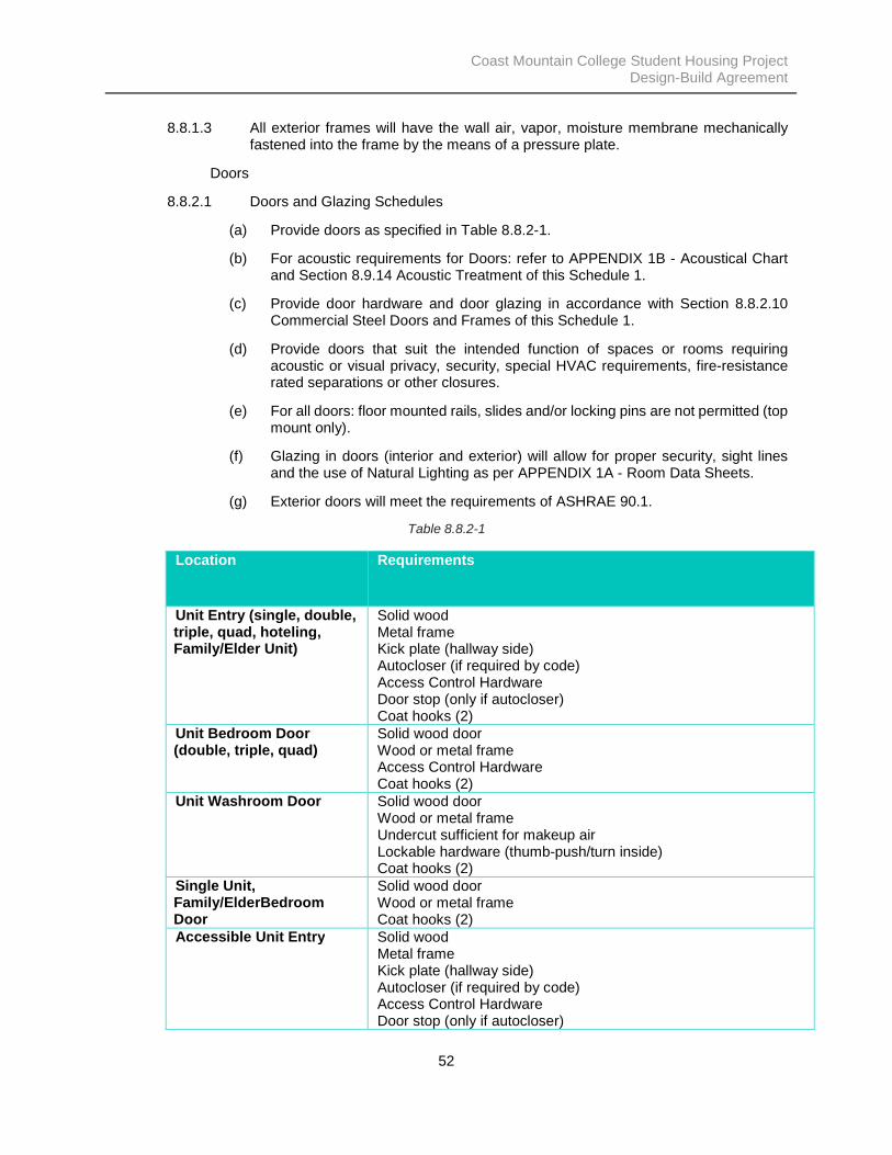
Coast Mountain College Student Housing Project Design-Build Agreement
52
8.8.1.3 All exterior frames will have the wall air, vapor, moisture membrane mechanically fastened into the frame by the means of a pressure plate.
Doors
8.8.2.1 Doors and Glazing Schedules
(a) Provide doors as specified in Table 8.8.2-1.
(b) For acoustic requirements for Doors: refer to APPENDIX 1B - Acoustical Chart and Section 8.9.14 Acoustic Treatment of this Schedule 1.
(c) Provide door hardware and door glazing in accordance with Section 8.8.2.10 Commercial Steel Doors and Frames of this Schedule 1.
(d) Provide doors that suit the intended function of spaces or rooms requiring acoustic or visual privacy, security, special HVAC requirements, fire-resistance rated separations or other closures.
(e) For all doors: floor mounted rails, slides and/or locking pins are not permitted (top mount only).
(f) Glazing in doors (interior and exterior) will allow for proper security, sight lines and the use of Natural Lighting as per APPENDIX 1A - Room Data Sheets.
(g) Exterior doors will meet the requirements of ASHRAE 90.1.
Table 8.8.2-1
Location Requirements
Unit Entry (single, double, triple, quad, hoteling, Family/Elder Unit)
Solid wood Metal frame Kick plate (hallway side) Autocloser (if required by code) Access Control Hardware Door stop (only if autocloser) Coat hooks (2)
Unit Bedroom Door (double, triple, quad)
Solid wood door Wood or metal frame Access Control Hardware Coat hooks (2)
Unit Washroom Door Solid wood door Wood or metal frame Undercut sufficient for makeup air Lockable hardware (thumb-push/turn inside) Coat hooks (2)
Single Unit, Family/ElderBedroom Door
Solid wood door Wood or metal frame Coat hooks (2)
Accessible Unit Entry Solid wood Metal frame Kick plate (hallway side) Autocloser (if required by code) Access Control Hardware Door stop (only if autocloser)

Coast Mountain College Student Housing Project Design-Build Agreement
53
Coat hooks (4) (high and low) Auto operating switch / operator
Accessible Unit Bedroom Solid wood door Wood frame Coat hooks (2, high and low) Auto operating switch / operator
Accessible Unit Bathroom Solid wood door Wood or metal frame Undercut sufficient for makeup air Lockable hardware (thumb-push/turn inside) Coat hooks (2, high and low) Auto operating switch / operator
Wing separation door Solid wood, aluminum or metal door (rated as required) Metal or aluminum frame Kick plate (if wood, both sides) Autocloser w/ coordinators (if pair) Access Control Hardware Auto operating switch / operator Glazing Sidelight
Janitorial, Comm., Lobby Storage
Solid wood door Metal frame Kick plate (both sides) Autocloser (if required by code) Access Control Hardware Door stop (only if autocloser)
Cultural Space Solid wood door Wood or metal frame Glazing Sidelight (300mm min) Autocloser (if required by code) Access Control Hardware Door Stop (if autocloser)
Project Room(s) (closed), Computer Lab, Esports Room,
Solid wood or aluminum Metal or aluminum frame Glazing Sidelight (300mm min) Access Control Hardware Autocloser (if required by code) Door Stop (if autocloser)
Laundry Solid Wood Door Metal Frame Non-locking hardware Autocloser Door Stop Auto operating switch / operator Kick plate, both sides Glazing
Universal Washroom(s) Solid Wood Door Metal Frame Thumb-turn hardware w/ Occupancy indicator Coat hooks (2)
Universal Washroom, Accessible
Solid Wood Door Metal Frame Auto operating switch / operator

Coast Mountain College Student Housing Project Design-Build Agreement
54
Thumb-turn hardware w/ Occupancy indicator Coat hooks (2, 1 high, 1 low)
Admin Office Solid Wood Door Metal Frame Access Control Hardware Glazing Sidelight
Entry Door(s), Patio access doors
Metal, solid wood or Aluminum Metal or Aluminum frame Glazing Sidelights Access Control Hardware Auto operating switch / operator Panic hardware
Vestibule (interior) Metal, solid wood or Aluminum Metal or Aluminum frame Glazing Sidelights Auto operating switch / operator Panic hardware
Egress Stair (interior) Solid Metal Door Metal Frame Panic hardware Glazing Free access from stair to hallway
Egress Stair (Exterior) Solid Metal Door, Insulated Metal Frame (insulated) Panic hardware Access control from exterior
Electrical, Mechanical Solid Metal Door Metal Frame Access Control Hardware Rating as required
Bicycle Storage Solid Metal Door Metal Frame Access Control Hardware Rating as required
8.8.2.2 Size Requirements for Doors
(a) Provide door openings of adequate width to suit the intended purpose of rooms on either side of the doors and also allow the movement of people and equipment associated with those rooms.
(b) Pairs of Building entry doors will be a minimum of 915 wide each and 2440mm high.
(c) Pairs of doors leading to exterior patio will be a minimum of 915 wide each and 2440mm high.
(d) Door to Bicycle storage will be a minimum of 1067 wide and 2440mm high.
(e) Mechanical and electrical room doors are to be sized to move pieces of equipment in or out over the Design Life of the Building, and no less than 1067 wide and 2440 high.

Coast Mountain College Student Housing Project Design-Build Agreement
55
(f) For spaces with equipment that would not fit through the door size noted above, provide alternate means for allowing equipment replacement for larger clearance requirements.
(g) Apply door sizes and designs consistently to rooms of similar use, location, and configuration.
(h) Do not permit doors swinging into corridors in a manner that may obstruct traffic flow or reduce the corridor width or inhibit egress, except doors to spaces that are used infrequently and are not subject to occupancy such as small closets.
8.8.2.3 Finish Hardware
(a) Finish hardware will comply with all applicable Standards, including the quality standards of the Door and Hardware Institute (DHI).
(b) Provide all finish hardware from one supplier that is a member in good standing of the Door and Hardware Institute (DHI) and has in its employ one or more AHC (Architectural Hardware Consultant).
(c) Hardware will be integrated with the security requirements and coordinated with electrical wiring and power requirements.
(d) Select finishes providing maximum longevity and preservation of the finish.
(e) Provide, where applicable, ULC-listed hardware for the required fire rating.
(f) Use commercial grade hardware, excluding the interior spaces of Living Units; locksets and latch sets and lever handles of solid material.
(g) Provide all doors with bumper protection at walls to avoid damages.
(h) All doors are to have a minimum of (3) hinges.
(i) Door sweeps are to be provided on all exterior doors.
(j) Provide glazing in doors and sidelights in such a way that they allow for appropriate operational requirements of the spaces they serve.
8.8.2.4 Keying
(a) Provide key cylinder to match Everest 29 S123, or acceptable equivalent, to allow compatibility with the remainder of the Campus. In order to be acceptable, any proposed equivalent must be fully compatible with and be demonstrably capable of being seamlessly integrated with the Everest 29 S123 system that is currently in use by the Owner.
(b) Provide hard wired access control door hardware to allow remote control and programming of any door on the system. In order to be acceptable, any proposed equivalent must be fully compatible with and be demonstrably capable of being seamlessly integrated with the system that is currently in use by the Owner.
(c) Basic Requirements
(i) The Design-Builder will prepare and submit a proposed key schedule for the Building, during the development of construction drawings. The proposed key schedule will include details of the master keying system for the Building and will minimize the requirement for Staff to carry keys and the number and type of keys required for the Building.

Coast Mountain College Student Housing Project Design-Build Agreement
56
(ii) Provide a restricted keyway system for all lock cylinders in the Building. The restricted keyway system will be obtained from the applicable lockset manufacturer(s) on behalf of, and in the name of, the Owner. The Owner will control the restricted keyway system, such that all spare keys and key blanks will be ordered by an authorized representative of the Owner.
8.8.2.5 Hollow Metal Doors and Frames
(a) Materials and manufacture of metal doors will comply with the requirements of the Canadian Steel Door and Frame Manufacturer’s Association (CSDFMA).
(b) Installation methods and locations for doors, frames, and hardware will conform to DHI standards for detention facilities.
(c) Interior metal doors will have flush faced construction and be provided complete with all hardware, components and finishes required to suit the intended function of the door within the Building and the aesthetics of the Building.
(d) Provide interior metal doors with flush face construction and continuously welded edge seams.
(e) Doors with an inactive leaf will not be floor bolted. Bolt into frame instead.
(f) Provide exterior metal doors with:
(i) flush face construction, continuously welded, seamless edge construction using steel sheet;
(ii) edge seams to correspond with door function and minimize maintenance needed;
(iii) prepared surfaces to receive finishes that resist corrosion from exposure to weather. Provide with ZF180 coating; and
(iv) all exterior doors that open out will be capped to avoid water collecting in welding channels.
(g) Provide pressed metal frames with:
(i) fully welded construction of the same gauge at frames as at doors;
(ii) thermally-broken door frames for exterior, non-fire rated openings; and
(iii) anchors to each jamb to suit wall type and receive the frame
8.8.2.6 Door Glazing
(a) For exterior hollow metal door glazing, use sealed units with warm edge, argon filled space in thermally-broken frames to prevent heat loss.
(b) Exterior glazing at doors and side lights will be laminated.
(c) For interior hollow metal door glazing use tempered glass.
8.8.2.7 Wood Doors
(i) All wood doors will comply with all applicable Standards, including the Quality Standards for Architectural Woodwork published by the Architectural Woodwork Manufacturer’s Association of Canada (AWMAC) and Door and Hardware Institute (DHI) standards.

Coast Mountain College Student Housing Project Design-Build Agreement
57
(ii) Wood doors will have hardware and finishes that suit the intended function and aesthetics of the Building. Use Grade A faces for transparent finish. Factory finish is required for doors with transparent finish; use UV-cured polyurethane finish system. All wood door edges will be sealed.
(iii) Provide heavy duty commercial grade wood doors in flush design, Custom Grade quality (as defined in the AWMAC standards referred to above), 5-ply bonded particleboard core.
(iv) All wood doors and frame will have a polyurethane finish.
(v) All wood doors will resist Malicious Damage and damage from expected use.
(vi) All wood doors will be easily maintainable and repairable.
(vii) All wood doors will comply with fire resistance requirements when used in a rated wall assembly.
(viii) All wood doors will be sized, constructed and be provided complete with all hardware, components and finishes required to suit the intended function of the door within the Building and the aesthetics of the Building.
(ix) Construction, finish, and installation of all wood doors will minimize the requirement for maintenance and resulting disruption to operation of the Building.
(x) All wood doors will be flush custom grade quality, solid MDF core.
(xi) Frames will wrap around the wall assembly they are installed into, such that the frame projects a minimum 13 mm proud of the face of the wall each side of the frame.
(xii) Frames will be compatible with adjacent wall assembly (in terms of anchorage, fire protection, weight of door and repetitive slamming).
(xiii) All frames will be welded construction. Knock down type frames are not permitted.
(xiv) Doors with an inactive leaf will not be floor bolted. Bolt into frame instead.
(xv) Provide fire-resistance rated doors with a homogeneous incombustible mineral core and AWMAC Quality Standards Option 5 blocking.
(xvi) Install finish hardware securely. Fasten to solid wood backing, except where hardware is designed to be through-bolted.
(xvii) Glue stiles, rails and faces to the core with Type II water-resistant adhesive to minimize de-lamination or disassembly as a result of moisture ingress.
(xviii) Use B-Grade hardwood veneer with AWMAC No. 3 edge, finish to suit the intended use.
(xix) Provide stainless steel door edge guards on wood doors in areas accessible to students and in areas where door abuse is expected.

Coast Mountain College Student Housing Project Design-Build Agreement
58
8.8.2.8 Interior Aluminum Sliding Doors and Sidelights
(a) Interior sliding doors and sidelights will have recessed mounted track with sliding and fixed panel(s), and include single glazing with 6 mm clear fully tempered float glass
8.8.2.9 Aluminum Entrances and Storefronts
(a) Aluminum entrances, curtain wall fabrications and doors may form part of the exterior envelope of the Building or provide glazed interior partitions.
(b) Aluminum doors will be used within aluminum entrances and CWF.
(c) Aluminum entrances and storefront framing and doors may form part of the exterior
(d) Provide glazed interior partitions as appropriate to comply with the functions of the spaces as defined by the APPENDIX 1A - Room Data Sheets.
(e) Use frames that are thermally-broken, flush glazed, aluminum sections, to accept insulating glass units.
(f) Incorporate in the frames drained and vented system [rain screen] with a complete air and vapor seal, allowing any moisture entering the frame to drain to the exterior and allowing air into the pressuring chamber.
(g) Apply aluminum finish for exposed aluminum surfaces. Finish to be permanent and resistant to corrosion caused by weather exposure and climate.
8.8.2.10 Commercial Steel Doors and Frames
(a) Fabricated complete with cut outs and reinforcing and drilled and tapped to receive the finish hardware.
(b) Surfaces prepared to receive finishes. Door surfaces will be prepared to resist corrosion.
(c) Flush faced construction to meet the aesthetic, functional and maintenance performance requirements and the weather and climatic conditions of the Site.
(d) Commercial Steel Doors will:
(i) be heavy duty, welded construction commercial grade doors;
(ii) be resistant to expected use and abuse;
(iii) be easily maintainable and repairable;
(iv) have insulated cores.
(e) Commercial Steel Frames:
(i) be heavy duty, welded construction commercial grade frames. Knock down type frames are not permitted.
(ii) complete with anchors to each jamb to suit wall type to receive the frame.
(iii) fabricated complete with cut outs and reinforcing and drilled and tapped to receive the finish hardware.

Coast Mountain College Student Housing Project Design-Build Agreement
59
(iv) exterior door frames to be thermally broken to prevent heat loss and condensation.
(v) surface preparation to suit the doors for which, the frames are installed.
8.8.2.11 Specialty Doors
(a) All specialty doors will:
(i) include a disconnect switch and power connection;
(ii) provide structural integrity capable of withstanding effects of gravity loads and wind loads, acting inward and outward;
(iii) include door assemblies capable of operating for not less than 125,000 cycles and for 50 cycles per day; and
(b) Performance Criteria
(i) Provide large opening doors of lightweight construction and that are durable. Provide a weather tight closure.
(c) Materials:
(i) Aluminum extrusions: Aluminum Association alloy 6063-T6.
(ii) Galvanized steel sheet: 3mm thickness, commercial quality to ASTM A653/A653M, with Z275 Designation zinc coating.
(iii) Assemble components by welding or mechanical fastening.
(iv) Provide structural steel reinforcement as required by manufacturer.
(v) Isolate aluminum from direct contact with dissimilar metals.
(d) Automatic Swing Doors
(i) Where used, provide electrified push button control devices
(e) Access Doors and Frames
(i) Performance Requirements:
1. Fire-rated vertical access doors and frames: NFPA 252 or UL 10B; and
2. Fire-rated horizontal access doors and frames: NFPA 288.
(ii) Hardware: Hinges, two key operated flush self-latching locks.
Exterior Windows General
8.8.3.1 Exterior glazing will be a minimum of 20% of the Building exterior calculated as an average of all floors above and including the main entry level.
8.8.3.2 Glazing will provide for excellent optical clarity with ease of maintenance over time.
8.8.3.3 Design glazing and interior surrounds to allow uniform, unobstructed movement of conditioned air across the glass and frame.
8.8.3.4 Select glazing in consideration with the lighting and mechanical systems to prevent glare and solar overheating.

Coast Mountain College Student Housing Project Design-Build Agreement
60
8.8.3.5 Exterior Glazing
(a) Minimum performance requirements for all exterior glazing will include the following:
(i) As required to meet Building energy targets.
(b) Provide uniform glazing sizes for the purposes of maintenance and ease of replacement.
(c) Based on known local climatic data provide windows to Good Industry Practice that comply with the following standards:
(i) CAN/CSA-A440-00/A440.1-00, Windows and its appended Special Publication;
(ii) User Selection Guide to CSA Standard CAN/CSA-A440.1-00;
(iii) Windows: Aluminum Association Standards (AAS), and the American Architectural Manufacturers Association (AAMA) field testing specifications;
(iv) Air-tightness – per CAN/CSA-A440.0 and CGSB Requirements 82.1.
(d) All exterior glazing will be installed and maintained from the exterior of the Building.
(e) Provisions will be made in the building cladding for maintenance of the exterior glazing.
8.8.3.6 Window Types
Window Type Location Requirements Glazing Type
Type 1 Living Units, Cultural Space, Esports room, Small Project Rooms (closed), Small Project Rooms (open), Computer Lab
• Operable • Stop limits to prevent
falls • Double or Triple paned • Window Screens • Min 915 x 1200mm • Sill to be 915mm A.F.F.
Exterior
Type 2*Note: Type 2 can be used in place of Type 1
Student Lobby, Student Dining and Lounge
• Curtainwall or Storefront
• Operable venting near seating areas
Exterior
Type 3 Cultural Space • STC-20 minimum • Fixed glazing • Window film (optional)
Interior
Type 4 Office, Computer Lab, Small Project Room (closed), Large Project Room
• STC-20 minimum • Fixed glazing • Unitized system w/
door
Interior
Type 5 Separation between Student Dining and Lounge / Student
• STC-20 minimum • Laminated
Interior

Coast Mountain College Student Housing Project Design-Build Agreement
61
Lobby, and Living Unit hallways
• Fixed glazing • Unitized system w/
door
8.8.3.7 Aluminum Curtain Walls
(a) Aluminum curtain walls will comply with all applicable Standards, including the Aluminum Association Standards (AAS) and the American Architectural Manufacturers Association (AAMA) field testing specifications.
(b) Incorporate in the curtain wall framing a drained and vented system complete with air and vapor seal, allowing any water entering the framing/system and the glazing detail cavities to drain to the exterior and also allow air into the pressuring chamber.
(c) Provide curtain wall framing that incorporates a thermal-break.
(d) For exposed aluminum surfaces, provide a finish that is permanent and resistant to corrosion resulting from weather exposure and climate.
(e) Provide assemblies that resist local seismic conditions and 1-in-100 year climatic events.
(f) Applied solar films are not permitted.
8.8.3.8 Aluminum Windows
(a) Aluminum windows will comply with all applicable standards, including the Aluminum Association Standards (AAS) and the American Architectural Manufacturers Association (AAMA) field testing specifications. Provide Architectural Grade windows unless otherwise noted.
(b) Incorporate in windows a drained and vented system complete with air and vapor seal, allowing any water entering the framing/system and the glazing detail cavities to drain to the exterior and also allow air into the pressuring chamber.
(c) Provide windows that incorporate a thermal-break.
(d) For exposed aluminum surfaces, Provide a finish that is permanent and resistant to corrosion resulting from weather exposure and climate.
(e) Provide assemblies that resist local seismic conditions and 1-in-100 year climatic events.
(f) Applied solar films are not permitted.
8.8.3.9 Aluminum Framing Systems
(a) Anchors for the framing will be located within the vertical tube sections or on the sides of the tubes as strap anchors. The anchors are to be designed to allow for thermal expansion and contraction of the frame. The design of the anchors will not interfere with the adhesion of the air, vapor, and moisture membranes from the wall directly to the tube face of the section.
(b) Mechanically retain the air seal membrane to the tube face of the section with the use of an aluminum anti-rotation channel or equivalent.
(c) Gaskets and weather seals will be mechanically keyed in dry glazing systems for both interior and exterior applications (visionstrip is not considered a mechanically keyed gasket).

Coast Mountain College Student Housing Project Design-Build Agreement
62
8.8.3.10 Clerestory Glazing
(a) For exposed aluminum surfaces, provide a finish that is permanent and resistant to corrosion resulting from weather exposure and climate.
(b) Glazing slope will be 30° or greater.
(c) Clerestory windows will be fully accessible for maintenance and cleaning from the interior and exterior of the Building without disruption to the Building operations.
(d) Air seal and water seal connections to curbs and walls will be fully accessible and will not be dependent on construction sequence.
(e) Provide drainage of water entering the glazing system to the exterior under all conditions.
(f) Design glazing to prevent condensation on the interior face of the glazing or framing system. Provide interior gutters to catch water in the event condensation occurs. Drain condensation gutters to the interior.
(g) Provide dry glazing.
(h) Glazing framing systems will provide for the mechanical attachment of air, vapor, and moisture membranes.
8.8.3.11 Tubular Natural Lighting Devices (light tubes)
(a) Tubular natural lighting devices are permitted where required to provide necessary Natural Light to interior spaces.
(b) Provide tubular natural lighting devices as follows:
(i) transparent roof mounted skylight dome and self-flashing curb, reflective tube and ceiling level diffuser assembly;
(ii) complying with the International Code Council ICC AC-16; and
(iii) minimum tube diameter to be 530mm.
8.8.3.12 Glass and Glazing
(a) Glass and glazing will comply with all applicable Standards, including the Insulating Glass Manufacturers Association of Canada [IGMAC] Guidelines and the Glazing Contractors Association of B.C. [GCA] Glazing Systems Specifications Manual.
(b) Provide assemblies that resist local seismic conditions as defined in the BC Building Code.
(c) Provide assemblies that resist 1-in-100 year climatic events.
(d) Use laminated safety glass in entry doors and sidelights, or as the inboard light of a double-glazed skylight.
Interior Windows
8.8.4.1 General Requirements
(a) Provide windows as specified APPENDIX 1A - Room Data Sheets.

Coast Mountain College Student Housing Project Design-Build Agreement
63
(b) Where not specified, size, configure, and adequately construct windows to suit rooms that require Natural Light, views and/or natural ventilation.
(c) Coordinate glazing heights with adjacent wall protection, handrails, and other accessories to achieve functional and aesthetic cohesiveness.
8.8.4.2 Performance Criteria
(a) be conventional commercial grade window construction; and
(b) provide normal security and resistance to abuse.
8.8.4.3 Interior Glazing Selection Criteria
(a) All windows are to be able to be re-glazed in place.
8.8.4.4 Interior Glazing Schedule
(a) Doors & Borrowed Lites: minimum 6mm Tempered and as required to maintain overall wall acoustic requirements.
(b) Exit and corridor doors: 6mm Tempered.
8.9 Division 9 – Finishes
Basic Requirements
8.9.1.1 Select the appearance of finishes and colours to create and promote a calm and respectful environment, prevent glare, and minimize artificial lighting requirements.
8.9.1.2 Materials and assemblies will be designed and constructed to minimize maintenance requirements.
8.9.1.3 In areas where finishes and systems of installation will occur and water is anticipated to be present as part of cleaning or other procedures, allow water to collect and exit without causing damage to the finishes or substrate.
8.9.1.4 In areas where finishes or systems of installation may come in contact with water, chemical agents or other liquids as part of cleaning or other procedures, water, chemical agents or other liquids will be allowed to collect and exist without causing damage to the finishes or substrate.
8.9.1.5 Interior finish materials will have surface finishes either as manufactured and integral to the finish material or as applied to the surface of the finish material by paint or special coating.
8.9.1.6 Interior materials will be of a high performance quality to withstand regular and repeated abuse and cleaning.
8.9.1.7 Interior materials subject to corrosion from exposure to moisture or other corrosive agents and where painting is insufficient to protect from corrosion/damage will receive a special protective coating sufficient to protect against corrosion. Such materials include interior masonry in Shower, structural and miscellaneous steel and galvanized steel.
8.9.1.8 Provide acoustic wall treatment as required to meet the acoustic requirements specified in APPENDIX 1B - Acoustical Chart and Section 8.9.14 Acoustic Treatment of this Schedule 1.

Coast Mountain College Student Housing Project Design-Build Agreement
64
Performance Criteria
8.9.2.1 Floor finishes will be Class A “institutional and commercial floors” and have gaps less than or equal to 8.0mm under a 3000mm straight edge. Only a single curvature within this distance is allowed, unless specified otherwise in this Schedule 1.
8.9.2.2 Where floor drains are specified elsewhere in this Schedule 1, the floors will be designed and constructed with positive drainage to the drains so as to prevent any ponding of water or other fluids.
Interior Walls and Partitions
8.9.3.1 Basic Requirements:
(a) Design and construct the interior Building components of the Building in accordance with the following:
(i) provide acoustic separations as required to account for the specific functions to be carried out in the relevant spaces affected as specified in this Schedule 1;
(ii) design and select interior walls and partitions, partition systems and interior finishes:
1. for ease of cleaning and maintenance;
2. to maximize permanence and durability, including impact resistance;
3. to maximize flexibility and adaptability of services;
4. with Low VOC emissions so as to minimize adverse impact on indoor air quality and indoor environmental quality;
5. acoustic requirements as specified in APPENDIX 1B - Acoustical Chart and Section 8.9.14 Acoustic Treatment of this Schedule 1; and
6. accommodate required building services without compromising security and safety.
8.9.3.2 Use of steel framing
(a) Interior wall framing will comply with all applicable Standards, including the Canadian Sheet Steel Building Institute Standards (CSSB1) and the Association of Wall and Ceiling Contractors of B.C. (AWCC) Wall & Ceiling Specification Standards Manual for materials and workmanship for interior walls, including steel studs and furring and GWB ceiling suspension systems.
(b) Use prefabricated non-load bearing steel studs for interior partitions and furring with no axial load other than its own weight, the weight of attached finishes, and lateral loads of interior pressure differences and seismic loads.
(c) Construct steel stud framing to accommodate electrical, plumbing and other services in the partition cavity, and to support fixtures, wall cabinets, and other such wall-mounted items. Provide reinforcement and backing.
(d) Account for in design, the differences in air pressure that may result on opposite sides of the wall or partition due to factors such as wind and other lateral pressures, stack effects, or mechanically-induced air pressurization.

Coast Mountain College Student Housing Project Design-Build Agreement
65
(e) Design assembly to accommodate construction tolerances, deflection of building structural members, and clearances of intended opening.
(f) Where GWB systems are required to provide fire resistance ratings, design wall assemblies tested by fire testing laboratories acceptable to Authorities Having Jurisdiction.
8.9.3.3 Performance Criteria
(a) The interior walls will be designed and constructed to provide a safe and secure place for Occupants, and provide the required level of fire rated protection stipulated by the BC Building Code.
(b) Materials and work quality for interior walls, including steel studs and furring and GWB ceiling suspension systems, will be to Good Industry Practice. Non-load bearing channel stud framing will conform to ASTM C 645 and CAN/CGSB-7.1-98.
(c) Interior walls and partitions system design and components will meet the seismic restraint requirements of the BC Building Code.
(d) The interior walls and partition systems will:
(i) provide acoustic separations of internal walls and partitions in accordance with APPENDIX 1B - Acoustical Chart and Section 8.9.14 Acoustic Treatment of this Schedule 1.
(e) All walls will be constructed floor to underside of structure above.
(f) Interior walls will be designed and constructed using durable materials and will be secured in a fashion.
Ceramic and Porcelain Tilework
8.9.4.1 Ceramic tiles will be applied on walls only.
8.9.4.2 Porcelain Tiles will be applied to floors only.
8.9.4.3 Dynamic Coefficient of Friction (DCFO) will be minimum:
(a) 0.55-0.56 for outdoor applications
(b) 0.42 for indoor Public Spaces
8.9.4.4 Ceramic tilework will comply with all applicable Standards, including the Terrazzo Tile and Marble Association of Canada (TTMAC) Specification Guide 09 30 13 Tile Installation Manual.
8.9.4.5 For installations on wet and exterior surfaces, use floor tiles that have the following static coefficients of friction as per the American Society for Testing and Materials International (ASTM):
(a) Level Surfaces: Not less than 0.50 for wet and dry conditions.
(b) Stair Treads: Not less than 0.60 for wet and dry conditions.
(c) Ramp Surfaces: Not less than 0.60 for wet and dry conditions.
8.9.4.6 For exterior installations, provide frost-resistant exterior tiles with a moisture absorption rating of 3.0% or less.

Coast Mountain College Student Housing Project Design-Build Agreement
66
8.9.4.7 Provide control joints and expansion joints in conformance with the recommendations of the TTMAC Tile Installation Manual.
8.9.4.8 Provide crack isolation membranes to resist crack transmission from the substrate due to lateral movement; design for use in thin-set applications of tile over a cracked substrate. Use elastomeric sheets or trowel-applied materials suitable for subsequent bonding of ceramic tile.
8.9.4.9 Set ceramic tile with latex modified mortar and all grout will be epoxy based.
8.9.4.10 Cementitious Board for Special Wall Coatings and Ceramic Tile Applications:
(i) Rigid lightweight concrete board;
(ii) Glass fibre reinforcing mesh each face;
(iii) Thickness: 16mm; and
(iv) Dimensions: Largest practical sheets to minimize joints.
Applied Acoustic Wall Treatment:
8.9.5.1 Requirements:
(a) Acoustic Wall Treatment Materials and Products – Wall Panels:
(i) composite wood fibre bonded with cement binders such as Tectum Panels; or
(ii) semi rigid fibre glass with hardened edges and wrapped in an acoustic transparent vinyl fabric.
Ceilings
8.9.6.1 Performance Criteria
(a) Ceiling reflectance will complement the lighting design.
(b) All ceiling systems and ceiling finishes will:
(i) provide permanence and durability appropriate;
(ii) comply with the acoustic requirements specified in APPENDIX 1B - Acoustical Chart and Section 8.9.14 Acoustic Treatment of this Schedule 1;
(iii) promote ease of cleaning and maintenance in order to minimize disruption;
(iv) white in colour unless wood;
(v) be compatible with mechanical, plumbing, electrical, building security and communications and ESCS services and fixtures;
(vi) be compatible with ceiling attached equipment; and
(vii) be architecturally aesthetic and suitable for the function of the space.
(c) All ceiling systems and ceiling finishes will comply with the following:
(i) fire and smoke separation and fire resistance ratings will conform to the requirements of all applicable codes;

Coast Mountain College Student Housing Project Design-Build Agreement
67
(ii) suspended ceilings will comply with seismic resistance as required by all applicable codes; and
(iii) requirements of the Specification Standards Manual as published by the Association of Wall and Ceiling Contractors of British Columbia (AWCC).
8.9.6.2 Acoustic Tile Ceilings
(a) Ceiling tiles will be used as specified in APPENDIX 1A - Room Data Sheets.
(b) Acoustic Panel: Non-directional, white ceiling panel, trim edge detail to fit a standard T-bar grid panel size.
(c) Provide accessibility to the ceiling spaces where access is required to mechanical, electrical or other service systems.
(d) Provide acoustical panels that are appropriate for the normal occupancy condition range and maximum 70% relative humidity. When the service use temperature and relative humidity are expected to exceed these ranges, use acoustical units specifically designed for such applications.
(e) Use tiles with scratch-resistant surfaces in any area where lay-in ceiling panels frequently need to be removed for plenum access.
(f) Interior sound levels will be controlled to facilitate a comfortable environment for Occupants and a safe working environment for Building Staff and so as to achieve the requirements of APPENDIX 1B - Acoustical Chart and Section 8.9.14 Acoustic Treatment of this Schedule 1.
(g) Acoustic ceiling tiles in a suspension system will be installed to provide the levels of sound attenuation to suit the intended function of the room and so as to achieve the requirements of APPENDIX 1B - Acoustical Chart and Section 8.9.14 Acoustic Treatment of this Schedule 1.
(h) Ceilings installed in Tenant Kitchen and any washrooms will be capable of being cleaned without wear.
8.9.6.3 Hard Ceilings
(a) Construct hard ceilings min of 13mm GWB where fire rating is not required. In fire rated rooms the GWB will be fire rated and the thickness of the GWB is to be determined by the rating required by the BC Building Code.
(b) Finish hard ceilings as per the paint specifications outlined in Section 8.9.9 Painting and Protective Coatings of this Schedule 1. Provide hard ceilings as specified on the APPENDIX 1A - Room Data Sheets.
Flooring
8.9.7.1 The floor and floor systems will be complementary and integral to the functional and aesthetic requirements of the interior space.
8.9.7.2 Provide a flooring solution that uses colour and pattern changes to break-up large expanses of areas, helps to define zones, and creates a visually interesting spaces.
8.9.7.3 Floor finishes will be used where required for one or more of the following reasons:
(a) protect the structural floor from wear or corrosion;
(b) provide an attractive appearance; or

Coast Mountain College Student Housing Project Design-Build Agreement
68
(c) for the comfort and safety of the user.
8.9.7.4 Floor finishes will be slip resistant in both wet and dry conditions.
8.9.7.5 Circulation spaces are to have carpet tile.
8.9.7.6 Solid Sheet Flooring
(a) Use solid sheet flooring for all rooms as specified in the APPENDIX 1A - Room Data Sheets.
(b) Performance Criteria
(i) Flooring will resist absorption of contaminants that can affect maintenance, durability, health of Occupants or emit odours.
(ii) Flooring will provide permanence and durability.
(iii) Flooring will provide ease of cleaning and maintenance.
(iv) Where applied coatings or sheet materials are provided the frequency of joints will be minimized.
(v) Floor materials will be impervious to concentrations and duration of moisture which may exist in a given location.
(vi) Flooring will not delaminate from the substrate under any service condition.
(vii) Patterns and textures will be compatible with the requirements of all applicable codes and standards, including pedestrian safety and egress.
(viii) Floor finishes, with the exception of carpet, will extend under all fitments.
8.9.7.7 Concrete Stain:
(a) Subcontractors used to install/apply concrete stains will have minimum 10 years verified experience in the installation of concrete floor treatment finishes.
(b) Moisture: Ensure concrete substrate is within moisture limits prescribed by flooring manufacturer prior to applying.
(c) Quality of products and workmanship: In accordance with the Specification Standards Manual as published by the British Columbia Floor Covering Association [BCFCA].
(d) Manufacturer's Technical Representative: The Design-Builder will cause the flooring manufacturer to provide a technical representative to inspect the surfaces to which a flooring treatment is to be applied to confirm that the substrate is acceptable for the application of flooring treatment. The Design-Builder will cause the manufacturer's technical representative to carry out regular Site inspections to ensure that the installation is carried out in accordance with manufacturer's installation instructions and that deficiencies are corrected.
8.9.7.8 Resilient Flooring
(a) Standard: Comply with Specification Standards Manual published by BCFCA (British Columbia Floor Covering Association).

Coast Mountain College Student Housing Project Design-Build Agreement
69
(b) Slip-resistant sheet vinyl will have a static coefficient of friction of not less than 0.6 on level surfaces and not less than 0.8 on ramps.
(c) Linoleum sheet flooring will have a homogenous core of primarily natural materials, consisting of linseed oil, wood flour, and resin binders mixed and calendared onto a natural jute backing. Weld all seams. Provide integral cove bases.
(d) Rubber flooring will be solid cushioned sheet or tile formulated with 100% virgin elastomers, reinforcing agents, soil-resisting agents, and migrating waxes compounded to create durability, excellent cleaning characteristics, and 0.08 dry coefficient of friction ad defined by ASTM D204-04. Stud designs to have chamfered edges with a sharply-defined edge at the top for higher slip resistance, easier cleaning, superior maintenance and low vibration design to minimize vibration and noise.
(e) Heat weld all seams.
(f) Finish flooring with high speed buffing as per manufacturer’s operational specifications. Do not apply sealer or wax.
8.9.7.9 Vinyl Sheet Floor Covering
(i) Sheet vinyl flooring with backing to ASTM F 1913, commercial.
(ii) Wear Resistance: Comply with ASTM C 501 taber abrasion test.
(iii) Homogenous construction.
(iv) To be PVC free.
(v) Slip resistant vinyl sheet: Static Coefficient of Friction of 0.6 on level surfaces and 0.8 on ramps.
(vi) Thickness: Not less than 3mm in areas where flooring does not abut similar flooring and 2.0mm minimum wear layer.
8.9.7.10 Rubber Sheet Floor Covering: Sheet rubber, prefabricated, calendared and vulcanized
(a) Unbacked Rubber Sheet Floor Covering: ASTM F 1859.
(b) Rubber Sheet Floor Covering with Backing: ASTM F 1860.
(c) Make transitions between two adjoining areas, new-to-new, flush.
8.9.7.11 Stair Coverings
(a) Provide tactile warning strips and stair nosings to assist the visually impaired.
(b) Abrasive Stair Nosings: Provide slip-resistant stair and landing nosings.
8.9.7.12 Where epoxy flooring is used in wet areas, use water and slip-resistant grade and prevent water or moisture transmission to the substrate. Terminate flooring at the walls in the form of 150mm high flash coved bases. Above 150mm high flash cove, taper flooring material to allow smooth transition of the wall protection over the flooring.
8.9.7.13 Use permanent, heavy-duty integral materials such as seamless quartz epoxy flooring in areas subject to moisture and heat over extended periods of time.

Coast Mountain College Student Housing Project Design-Build Agreement
70
8.9.7.14 The transition between epoxy flooring and sheet wall protection will be smooth. The wall protection will overlap the flooring.
8.9.7.15 Use water resistant and slip-resistant flooring in all washrooms.
8.9.7.16 Provide resilient flooring in service corridors, stairwells and service areas.
8.9.7.17 Use anti-static flooring materials for Telecommunication Rooms.
8.9.7.18 Carpets and Carpet Tiles
(a) Use carpeting that is certified under Canadian Carpet Institute/Canadian Rug Institute (CCI/CRI) Indoor Air Quality Program and having CRI/IAQ Label
(b) Use a carpet designed to accept wheelchair traffic.
(c) Static Level: Maximum 3.5 kV static generation at 21ºC and 20% relative humidity per AATCC-134, throughout life of product.
(d) Emissions: Maximum 0.5 mg/m2/hr TVOC, after installation per Carpet and Rug Institute CRI Green Label Plus™ Indoor Air Quality Carpet Testing Program.
(e) Provide non-solvent, non-toxic, odorless adhesive that, when installed, maintains an acceptable VOC concentration and emission rate. Carpet cannot have a PVC backer.
(f) Carpet and Carpet tiles will:
(i) be 100% solution dyed nylon
(ii) have minimum Tarr rating of 3.0
(iii) have CRI green label plus for carpet tile and adhesive
(iv) have non-PVC backing
(v) have a minimum 10 year wear, stain, structural integrity and delamination warranty.
Laminates
8.9.8.1 Use high-pressure laminates on all horizontal surfaces.
8.9.8.2 Low pressure laminates are acceptable for vertical surfaces.
Painting and Protective Coatings
8.9.9.1 Comply with LEED® v4 requirements for Low VOC Emitting Materials, paints and coatings. Including the following:
(a) architectural paints, coatings and primers;
(b) anti-corrosive and anti-rust; and
(c) clear wood finishes, floor coatings, stains and shellacs.
8.9.9.2 Materials containing lead or mercury are not permitted.
8.9.9.3 Paints and coatings will meet the applicable flame spread requirements of applicable governmental authorities and the BC Building Code.
8.9.9.4 Use only materials having a minimum MPI 'Environmental Friendly' E2 rating or better based on VOC (EPA Method 24) content levels.

Coast Mountain College Student Housing Project Design-Build Agreement
71
8.9.9.5 If seamless epoxy wall coatings are used, provide a two component, high solids, zero or low VOC, solvent free, epoxy glaze wall coating which will be seamless, abrasion and chemical resistant, and UV resistant. Coatings will have been tested in accordance with ASTM D1308-Standard Test Method for Effect of Household Chemicals on Clear and Pigmented Organic Finishes.
8.9.9.6 Paint Gloss: Paint gloss is defined as the sheen rating of applied paint, in accordance with the following values:
(a) Gloss Level 1: Flat or matte: max. 5 units @ 60 degrees to a maximum of 10 units @ 85 degrees. NOT PERMITTED;
(b) Gloss Level 2: High Sheen Flat (Velvet-like): max. 10 units @ 60 degrees to a maximum of 10 - 35 units @ 85 degrees. NOT PERMITTED;
(c) Gloss Level 3: Eggshell: max. 10 - 25 units @ 60 degrees to a maximum of 10 – 35 units @ 85 degrees. LIMIT USE TO ADMIN OFFICE AND CEILINGS;
(d) Gloss Level 4: Satin-like Finish: max. 20 - 35 units @ 60 degrees to a minimum of 35 units @ 85 degrees. ALL SPACES.
(e) Gloss Level 5: Semi-gloss Finish: max. 35 - 70 units @ 60 degrees. DOORS AND FRAMES AND OTHER INTERIOR METAL WORK
(f) Gloss Level 6: Gloss Finish: max. 70 - 85 units @ 60 degrees. and
(g) Gloss Level 7: High Gloss Finish: More than 85 units @ 60 degrees. NOT PERMITTED.
8.9.9.7 Wood finish doors
(a) Use clear coat interior rub varnish for all wood finish doors.
8.9.9.8 Floors, concrete
(a) Use a 2-component (base component A, curing agent B).
8.9.9.9 Paint exposed conduit & services and any electrical panel boards to match the adjoining surface for finished appearance.
8.9.9.10 Use exterior paints of a quality designed to protect substrate materials from weather and climate conditions.
8.9.9.11 Achieve a visually harmonious and aesthetically coordinated appearance across all areas of the Building.
8.9.9.12 Use exterior and interior finish materials with surface finishes either as integral to the finish material or field-applied separately to the surface of the finish material.
8.9.9.13 Treat exterior masonry materials such as brick and concrete block with water-repellent coatings to prevent water ingress into or through the material.
8.9.9.14 Paint handrails, doors, and frames with a contrasting colour from walls in consideration of the visually impaired.
Vinyl Acrylic Wall Covering
8.9.10.1 Where vinyl/acrylic wall covering is used, provide vinyl/acrylic high impact rigid sheet, minimum 15mm thickness with colour-matched vinyl/acrylic trim for joint/transitions.

Coast Mountain College Student Housing Project Design-Build Agreement
72
8.9.10.2 Furnish complete packaged system containing all primers and adhesive. Use water-based and non-hazardous primer and adhesive materials.
Applied Sheet Wall Protection
8.9.11.1 Sheet wall protection will be applied to all corridors. Refer to Section 8.10.6 and 8.10.7 of this Schedule 1 for requirements.
8.9.11.2 Sheet wall protection will be:
(a) PVC free
(b) Fire and smoke performance: Class A per CAN/ULC-S102.1
(c) Smooth or minimally textured without visual fasteners
(d) Colour to compliment or match surrounding wall colour
Dry Erase Wall Covering
8.9.12.1 Provide pigmented gloss vinyl wall covering presentation surfaces for dry erase markers, including .61 kg/m2, non-woven backing as specified in APPENDIX 1A - Room Data Sheets.
8.9.12.2 Provide trim and other accessories including but not limited to wall covering trim of anodized aluminum, low profile trim.
8.9.12.3 For the rooms listed in APPENDIX 1D – Equipment List as having whiteboards; the Design-Builder will provide either a whiteboard or dry erase wall covering to be determined pursuant to the Review Procedure.
Interior Window Film
8.9.13.1 4.7mil vinyl, frosted
8.9.13.2 Applied to inner face of glazing. Edges not to be captured within window stops to be able to replace film as necessary
8.9.13.3 Privacy film: 50% opacity to obscure recognition of interior / exterior features
Acoustic Treatment
8.9.14.1 Design and construct the Building to comply with the minimum sound transmission ratings between spaces described in ratings in accordance with STC ratings in accordance with ASTM E90 and as set out Section 8.9.9 Acoustic Treatment of this Schedule 1 and APPENDIX 1B - Acoustical Chart, and noise isolation class, to standards set out in Section 8.9.9 Acoustic Treatment of this Schedule 1 and APPENDIX 1B - Acoustical Chart. Sound performance to be verified by testing.
8.9.14.2 All spaces must be designed to permit intelligibly heard conversations. Spaces to comply with sound transmission ratings in Section 8.9.9 Acoustic Treatment of this Schedule 1 and APPENDIX 1B - Acoustical Chart.
8.9.14.3 In addition, provide acoustic treatment where sound attenuation, soundproofing or other sound control measures are necessary.
8.9.14.4 Sound control will include:
(a) attenuation of sound within public, Occupant environments;
(b) sound isolation between the exterior and interior spaces;

Coast Mountain College Student Housing Project Design-Build Agreement
73
(c) sound isolation between interior spaces within each Building at both horizontal and vertical separations;
(d) sound and vibration isolation of building service noises and sound isolation of building service rooms; and
8.9.14.5 Design partition and ceiling construction to provide approximately the same degree of sound control through each assembly. When a partition is used for sound isolation, extend the sound control construction from slab to slab.
8.9.14.6 Optimum sound isolation requires that the integrity of GWB partitions and ceilings [mass] never be violated by vent or grille cut-outs or items such as recessed cabinets and light fixtures. Where penetrations are necessary, minimize placing them back-to-back or next to each other. Stagger electrical boxes by at least one stud space. Use mineral fibre insulation to seal joints around all cut-outs such as electrical, television and other outlets, plumbing escutcheons, and recessed cabinets.
8.9.14.7 Minimize constructions such as ducts, rigid conduits, and corridors that act as speaking tubes to transmit sound from one area to another. At common supply and return ducts, provide sound attenuation liners at the diffuser and/or grill to maintain assemblies’ STC. Seal around conduit.
8.9.14.8 Isolate Structure-borne vibrations and sound with resilient mountings on vibrating equipment to minimize sound transfer to structural materials. Provide ducts, pipes, and conduits with resilient, non-rigid boots or flexible couplings where they leave vibrating equipment; isolate from the Structure with resilient gaskets and sealant where they pass through walls, floors, or other building surfaces.
8.9.14.9 Performance Criteria:
(a) the design will account for acoustic performance of structural system elements and will include vibration control; and
(b) provide noise control strategies, including:
(i) use of sound attenuating barriers and absorptive room surfaces to control noise transmission through the Building Structure and within rooms;
(ii) sound isolation strategies for the Building envelope and windows (including acoustic zoning, wall construction, glazing, and STC) to achieve the standards in Table 1, APPENDIX 1B - Acoustical Chart.
(iii) provision of noise control measures in response to the Site's noise conditions and to address occupancy requirements; and
(iv) use of planning strategies that resolve space relationships and Building circulation to minimize potential for occupancy-related acoustic problems.
8.9.14.10 Minimum Criteria for Construction:
(a) All interior partitions are to be constructed from top of floor structure to underside of slab.
(b) All perimeter joints between walls to floor, wall to wall, and wall to underside of structure will be acoustically sealed with a non-hardening mastic caulking compound.

Coast Mountain College Student Housing Project Design-Build Agreement
74
(c) Where services are installed in walls, services will not be installed back to back so as to create a path for noise between spaces.
(d) Where services run horizontally or in a vertical shaft, services will not create a pathway, such as ductwork, for transmission of noise between rooms.
(e) Noise control between different spaces will be in accordance with the STC Ratings set out in APPENDIX 1B - Acoustical Chart.
(f) Acoustic separations will comply with the STC requirements of APPENDIX 1B - Acoustical Chart.
8.10 Division 10 – Specialties
Exterior Signage and Wayfinding
8.10.1.1 identify the Building, drop-off areas, and similar information to easily and clearly navigate the Building; and
8.10.1.2 use universal symbols and graphics.
Interior Signage
8.10.2.1 Overriding Principles
(a) All Building signage will provide identification, information and assist in way finding and orientation.
8.10.2.2 Design Requirements
(a) Interior signage will be provided for all spaces and rooms, including spaces and rooms identified in the table below.
(b) Interior signage will be designed and constructed such that no signage materials can be removed by the students.
(c) Interior signage will be designed to provide direction for Occupants, and to inform Students of rules.
(d) The detailed requirements for signage language/terminology will be determined pursuant to the Review Procedure.
8.10.2.3 The Design-Builder will:
(a) provide a simple configuration of the Building circulation systems and functions so that way finding is inherently easy for members of the public who are not familiar with the Building.
8.10.2.4 Design the internal directional signs to include:
(a) installation of signage at each point at which a directional decision is required;
(b) using consistent terminology with consistent and predictable locations of signage;
(c) signage will identify every space in the Building and all directional information. Where required, additional braille language will be provided as determined in consultation with the Owner;
(d) signage required at each stairwell level;
(e) final signage wording will be determined pursuant to the Review Procedure.

Coast Mountain College Student Housing Project Design-Build Agreement
75
8.10.2.5 International symbols will be used where and as applicable;
(a) Coordinate final locations of all interior signage to satisfy Building operational requirements.
Key: A – Area Designation Signage
R – Room Identification Signage
Rn – Room Number and Identification Signage
D – Interior Directional Signage
X – Not Required Room Wall Mounted Door Mounted
Admin Office Rn
Universal Washrooms Rn
Student Dining and Lounge D
Large Project Room Rn
Janitor (main) Rn
Lobby Storage Rn
Janitor Rn
Cultural Space Rn
Collaboration Space (Open) X X
Small Project Room (Closed) Rn
Computer Lab Rn
Esports Room Rn
Tenant Kitchen Rn
Bicycle Storage Rn
Laundry Room Rn
Living Unit(s) (All) Rn
Mechanical / Electrical / Comm or Service Rooms
Rn
Elevator R, D
Stairs Rn
Washroom Accessories
8.10.3.1 Miscellaneous Washroom Accessories:
(a) Install washroom accessories in all washrooms of the Building.
(b) Determine the type, size, and number of accessories with regard for the numbers and categories of users.

Coast Mountain College Student Housing Project Design-Build Agreement
76
(c) Washroom accessories and installation will be in conformance to the BC Building Code requirements for persons with disabilities unless operational requirements are specified otherwise in the APPENDIX 1A - Room Data Sheets.
(d) Use accessories free from imperfections in manufacture and finish.
(e) Refer to APPENDIX 1A – Room Data Sheets for washroom accessories locations.
(f) Shower curtains will be on breakaway track or breakaway rod as appropriate.
(g) Coat hooks will be anti-ligature.
Mirrors
8.10.4.1 Provide specialty products manufactured for the specific purposes intended, and installed in strict accordance with the manufacturer’s directions.
8.10.4.2 For full wall unframed mirrors, use 6mm thick minimum float glass backed with electrolytically-applied copper plating. Grind smooth and polish all edges.
8.10.4.3 For wall mounted posture mirrors, use framed type; one piece, stainless steel channel frame with a No. 1 quality, 6mm thick float glass mirror backed with electrolytically applied copper plating. Back with galvanized steel.
8.10.4.4 Safety glazing is required in all washroom areas. Apply laminate to back of mirror. Tempered glass is not permitted.
Whiteboards
8.10.5.1 Provide and install, as specified in APPENDIX 1A - Room Data Sheets:
8.10.5.2 Provide whiteboards with extruded aluminum frames, accessory trays, maprails and maphooks.
8.10.5.3 Use non-toxic, water based lamination adhesive for whiteboards.
8.10.5.4 Will be manufactured for the specific purposes intended and installed in strict accordance with the manufacturer’s directions.
8.10.5.5 Will be sized appropriately for purpose.
8.10.5.6 Will be constructed of glass.
8.10.5.7 Surface Finish: For use with dry-erase markers wipe clean with dry cloth or standard eraser, and suitable for use as a projection screen.
Wall and corner guards
8.10.6.1 Provide protection on all walls and exposed corners within corridors to prevent damage due to impact from Occupant traffic.
8.10.6.2 Minimum wall protection height is 1220mm above the floor bases.
8.10.6.3 Wall protection will continue above any handrail/wall bumper to fully protect the wall from damage.
8.10.6.4 Apply sheet wall protection and bumper guards in other locations where the there is a potential for impact damage.
Coast Mountain College Student Housing Project Design-Build Agreement
77
Bicycle Storage
(a) Provide both long term and short term bicycle storage as specified in APPENDIX 1D – Equipment List.
(b) Outdoor bicycle storage will be:
(i) weather protected and in the vicinity of front door; and
(ii) consistent with open space design and Site furnishing objectives.
8.11 Division 11 – Equipment
Appliances
8.11.1.1 Refer to APPENDIX 1D – Equipment List.
8.11.1.2 All appliance selections are to be approved by Owner.
Maintenance Manuals:
8.11.2.1 Supply operating and maintenance instructions, including spare parts list and optional accessories for all items specified within this Section 8.11.
8.11.2.2 Identify each item, arranged in sequence and ensure the numbers correspond to the specifications and drawings.
8.11.2.3 Provide an itemized lead sheet at the front of the manual with a list of the contents and the name and phone number of the 24/7 available local service providers.
Laundry Services Equipment
8.11.3.1 Concept and Vision
(a) Provide equipment as described in the APPENDIX 1D - Equipment List.
(b) In the Laundry Room provide commercial laundry facilities, including washers and dryers and an ozone system sufficient to support the maximum number of possible Tenants.
(c) Laundry service is an ongoing Building requirement. Choice of equipment will emphasize ease/infrequency of maintenance with a view to minimal operational disruption.
Waste Equipment Requirements
8.11.4.1 Provide a concrete pad, min 2000 x 1500mm, accessible to the access road, screened from public view.
8.11.4.2 Refer to Refer to APPENDIX 1D – Equipment List for waste bin requirements.
8.12 Division 12 – Furnishings
Cabinets
8.12.1.1 Cabinet parts and sub-assemblies (doors, drawers, tracks and back panels) will be interchangeable in the field without requiring special tools. Doors and drawers will be interchangeable with doors and drawers in like-sized cabinets. Cabinets will be constructed so that a standard height drawer can be removed and two 1/2 height drawers installed in its place. Likewise, a cupboard door or doors can be removed and replaced by a like-sized combination of drawers or vice versa.

Coast Mountain College Student Housing Project Design-Build Agreement
78
8.12.1.2 All cabinets will conform to Architectural Woodwork Standards, First Edition, as issued by Architectural Woodwork Manufacturer’s Association of Canada (AWMAC). Comply with Quality Standards Manual for minimum “Custom Grade,” and DHI standards for the design, fabrication, materials, installation, and workmanship of finish carpentry and architectural woodwork.
8.12.1.3 Provide reinforced backing support for all fitments and fixed furnishings attached to frame constructed walls.
Window Coverings
8.12.2.1 Provide window coverings for:
(a) all exterior windows as specified on APPENDIX 1A - Room Data Sheets.
8.12.2.2 Window coverings will allow control of exterior light entering the room during Natural Light hours and provide privacy during Natural Light and non-Natural Light hours.
8.12.2.3 Window coverings will be fully coordinated and complementary with the interior design concept for their respective functional areas.
8.12.2.4 Use shading fabric of non-PVC or vinyl-coated polyester or fiberglass yarn that is waterproof, washable, rot-proof, flame-resistant, colourfast to light, glare-reducing, and able to control heat gain while providing external visibility.
8.12.2.5 Roller Shades
(a) Where used, roller shades systems will operate with a spring wrap mechanism, adjustment - free continuous qualified #10 nickel-plated brass ball chain (50-lb. test) and pulley clutch operating system. System will be chain operated with spring assist when required to reduce pull force to lift heavy or large shades. Fabric will be inherently anti-static, flame retardant, fade and stain resistant, light filtering, room darkening, & blackout fabrics providing 0% - 3% openness factors. Fabric weight 320g/m2 containing fiberglass, polyester, acrylic or vinyl laminates.
8.12.2.6 Shading Cloth
(a) Cloth will be waterproof, washable, rot proof, flame resistant, fungal and bacteria resistant, colourfast to light and will control heat gain and provide external visibility and reduction of glare.
(b) Cloth will be selected to suit design criteria for room and solar control and will be:
(i) visually transparent single-fabric;
(ii) room darkening shadecloth.
8.12.2.7 Shade Bands: Construction of shade band includes the fabric, the enclosed hem weight, shade roller tube, and the attachment of the shade band to the roller tube. Sewn hems and open hem pockets are not permitted.
(a) Fabrication
(i) Fabricate shadecloth to hang flat without buckling or distortion. Fabricate with heat-sealed trimmed edges to hang straight without curling or ravelling. Fabricate unguided shadecloth to roll true and straight without shifting sideways more than 3.0mm in either direction per 2440mm of shade height due to warp distortion or weave design. Fabricate as follows:

Coast Mountain College Student Housing Project Design-Build Agreement
79
1. provide battens in standard shades as required to assure proper tracking and uniform rolling of the shadebands;
2. for railroaded shadebands, provide seams in railroaded multi-width shadebands as required to meet size requirements and in accordance with seam;
3. provide battens for railroaded shades when width-to-height [W:H] ratios meet or exceed manufacturer's standards; and
4. blackout shadebands, when used in side channels, will have horizontally mounted, roll-formed stainless steel or tempered-steel battens not more than 915mm on center extending fully into the side channels.
Walk-Off Mats
8.12.3.1 To be provided by Owner.
8.13 Division 14 – Conveying Equipment
General
8.13.1.1 Provide an elevator system as described in this Schedule 1 to be used as:
(a) Transport for Occupants and Occupants with disabilities or health issues;
(b) Service elevators (transportation of furnishings and/or equipment);
8.13.1.2 Elevator operational functions will be programmable by the Owner, integrated with the Building Management System and have to ability provide local control when enabled by a card reader, key fob or key.
8.13.1.3 There will be no access to elevator shafts other than as required for maintenance.
8.13.1.4 Elevator sumps will remain dry under all conditions.
8.13.1.5 Elevator will have a fail-safe phone.
8.13.1.6 Durable elevator cab finishes (including stainless steel fronts as well as hand and bumper rails) will be provided. Finishes will be reviewed and approved in advance by the Owner as part of consultation with the Owner.
8.13.1.7 Elevator machine design will not require lubrication after installation.
8.13.1.8 Provide battery lowering operation of each elevator such that when the loss of normal power is detected, the battery lowering feature is activated. When normal power becomes available, the elevator will automatically resume operation.
Performance Criteria for Elevators
8.13.2.1 The elevator will have a minimum load capacity of 750kg and a vertical speed of no less than 2.0m per second.
8.13.2.2 Codes, by-laws, and regulations
(a) Provide equipment and perform work in accordance with all applicable Laws, including local, provincial and federal Laws, codes, by-laws, and regulations including:
(i) ASME A17.1/ CSA B44, and CSA B44.1; and

Coast Mountain College Student Housing Project Design-Build Agreement
80
(ii) CSA-C22.1 - Canadian Electrical Code, Part 1, Safety Standards for Electrical Installations.
(iii) Elevators will comply with equipment noise Section 8.9.9. of this Schedule 1 and APPENDIX 1B - Acoustical Chart.
8.13.2.3 Seismic requirements
(a) Elevator system will withstand the effects of earthquake motions determined according to CAN/CSA S832.
(b) Comply with Section 8.4 [Elevator Safety Requirements For Seismic Risk Zone applicable to the Building, or greater] in ASME A17.1/CSA B44 Safety Code for Elevators and Escalators.
Part 9 FACILITIES SERVICES
9.1 Division 21 – Fire Suppression
Fire Protection
9.1.1.1 Basic Requirements
(a) Provide a sprinkler system and all required equipment designed to the occupancy classification that it protects.
(b) Sprinklers subject to freezing temperatures will be protected by a dry system. Glycol systems will not be allowed.
(c) Pendant concealed quick response sprinklers will be provided in all areas with dropped ceilings with temperature ratings to suit the specific hazard area.
9.1.1.2 Performance Criteria
(a) All fire protection systems will be hydraulically sized to NFPA standards.
(b) All equipment and installation will be in accordance with manufacturers’ requirements.
(c) Fire department connection will be installed at a location approved by the local governmental authorities.
(d) Install fire extinguishers in a semi (unfinished areas) or fully recessed (finished areas) cabinet to the satisfaction of the Authority Having Jurisdiction.
9.2 Division 22 – Plumbing
Provide individual water, fire protection, natural gas, sanitary, and storm services as required and sized to suit the usage needs of the Building. Sewer, storm and water service penetrations will be designed for flexibility and movement. No service will be buried in concrete.
9.2.1.1 Basic Requirements
(a) All plumbing materials will be in accordance with the BC Plumbing Code and applicable ASPE Standards
(b) Provide utilities-grade meters for domestic water and natural gas.
(c) The meters will be used to accurately measure water flow and natural gas consumption in all flow conditions.

Coast Mountain College Student Housing Project Design-Build Agreement
81
(d) Provide the plumbing in such a manner as to avoid disruption to the operation of the Building during maintenance or repairs.
(e) Label all systems clearly, including painting and labelling of all pipes, ceiling identification dots, valve tagging, and emergency valve identification signage. The following pipe labeling and colour table will be followed:
Table 9.2.1-1 Pipe Labeling
Contents Background Colour Marking
(Background / Legend & Arrows)
Legend
Chilled Water Supply Blue / White CHILLED SUPPLY CHWS
Chilled Water Return Blue / White CHILLED RETURN, CHWR
Solar Water Supply Yellow / Black SOLAR SUPPLY
Solar Water Return Yellow / Black SOLAR RETURN
Heating Water Yellow / Black HEATING SUPPLY, HWS
Heating Water Yellow / Black HEATING RETURN, HWR
Make‑Up Water Yellow / Black MAKE‑UP WTR
Domestic Hot Water Supply Green / White DOM. HW SUPPLY, DHW
Dom. HWS Recirculation Green / White DOM. HW CIRC, DHWR
Domestic Cold Water Supply Green / White DOM. CW SUPPLY, DCW
Storm Water Green / White STORM
Sanitary Green / White SAN
Compressed Air (Non-Medical) Green / White COMP. A.
Natural Gas Refer to CGA code
Gas Regulator Vents Refer to CGA code
Fire Protection Water Red / White FIRE PROT. WTR
Heat Pump Supply Yellow / Black HT PUMP SUPPLY
Heat Pump Return Yellow / Black HT PUMP RETURN
Radiant Floor Supply Yellow / Black RAD FLR SUPPLY
Radiant Floor Return Yellow / Black RAD FLR RETURN
Condensate Drain Green / White COND
Steam Condensate Supply Orange / Black STM COND SUPPLY
Steam Condensate Return Orange / Black STM COND RETURN
Irrigation Water Per CSA B128.1
Non Potable Water Per CSA B128.1
Grey Water Per CSA B128.1

Coast Mountain College Student Housing Project Design-Build Agreement
82
(f) Ceiling Access Identification will be as follows.
(i) Provide 6mm (1/4") self-adhesive coloured dots to the T-bar framing, adjacent to panel to be removed or to access doors in solid ceilings. Identify the location of equipment concealed above as follows:
1. Yellow - Concealed equipment and cleaning access;
2. Black - Control equipment, including control valves, dampers and sensors;
3. Red - Fire and smoke dampers, fire protection equipment and fire system drains; and
4. Green – Heating water, chilled water, domestic cold water, domestic hot water isolation valves.
(g) Provide and install all fixtures and equipment to manufacturer’s specifications, standards, and instructions.
(h) Provide the water systems to ensure that water is supplied at the required pressures to all water outlets. Minimum water pressure will be maintained at 30 PSI to the most remote fixture.
(i) Provide durable materials to allow for 24 hour a day operation with minimal downtime. Domestic and non-potable water piping in the Building will be copper, ductile iron, stainless steel, CPVC, or Cross-linked Polyethylene (PEX). Sanitary and storm piping above ground in the Building will be cast iron or copper or PVC with 25/50 flame and smoke as required for the location it is being installed in.
(i) CPVC piping for domestic water applications will be a minimum of SDR 11, will have the 25/50 flame and smoke ratings, and will meet the requirements of CSA B137.6.
(ii) PEX piping is only permitted to be used within a Living Unit, and will meet the requirements of CSA B137.6.
(j) Domestic and non-potable water piping will be connected by soldering, brazing, threading, flange, roll grooved systems, solvent welded, or push-to-connect. Connections utilizing compression will not be used except for connection of trap primer lines run in the slab. Pressure piping will not be routed underslab. This includes piping such as fire and domestic water lines, ground source and non-potable water systems, gas, and any non-gravity based drainage systems.
(k) Provide services with easy access and serviceability and to avoid interference with other services during operation and maintenance activities. All equipment valves and serviceable items will be accessible and removable without adapting wall/ceiling finishes or structure.
(l) Provide floor drains in all mechanical, laundry, kitchen, janitorial, and washroom floors, and other areas as required by all applicable codes, recommended by ASPE, rooms noted in APPENDIX 1A - Room Data Sheets, and for all devices requiring these drains, and backflow prevention devices. Ensure all equipment drain piping is terminated at floor drains and floors slope to the drains.
(m) Provide domestic water strainers on the incoming services into the Building.
(n) All piping will be accessible. No in-slab piping is allowed except piping serving the trap primers.

Coast Mountain College Student Housing Project Design-Build Agreement
83
(o) In the case where pipe foundations are used to support the structure, all underslab piping will be supported (hung) from the concrete slab above. Hangers and rods will be of sufficient strength and installed at intervals sufficient to carry the pipe and load, at the required slope. Hangers and rods will be corrosion resistant. Install light-weight fill above all piping that is supported (hung) from the concrete floor/roof above.
(p) All storm drainage, domestic water piping, and exposed p-traps will be insulated in accordance with ASHRAE standard 90.1 and as required to prevent condensation from developing on the pipe. Where piping and / or piping components are subject to freezing, provide insulation and heat tracing. On life-safety systems, the heat trace system will be monitored and alarmed for malfunction or service disruption. Ensure that heat trace systems on life-safety systems will be on back-up power.
9.2.1.2 Performance Criteria
(a) Pumping systems for subsurface, storm, or sanitary drainage will include 100% redundancy (one redundant unit for each active unit). The storm / subsurface sump will have twin compartments for settling and pumping and will be sized to prevent short cycling of the pump. Provide local alarm and outputs to the BMS for high water levels, status, and pump failure.
(b) Insulate storm drainage, domestic water piping, cooling water and exposed p-traps throughout per BCICA quality standards. Where piping and/or piping components are subject to freezing, provide insulation and heat tracing. Provide canvass or vinyl service jacket on all exposed insulation inside, provide aluminum jacketing outside. Ensure life-safety systems are not installed in locations subject to freezing.
(c) Provide drainage as required to alleviate water pressure exerted onto the bottom of foundations and/or floor slabs.
(d) Provide flushing and disinfection of domestic water systems to AWWA and CSA standards. Provide independent testing of piping systems once flushing and cleaning has been completed.
(e) Provide trap primers in drains that are subject to losing the trap seal.
(f) Conceal all sanitary, waste, and water piping in walls. Only trap arms and water supply piping will be exposed. Fixture outlet piping for adjustable height fixtures will be installed so that no water can collect in the piping at any fixture height.
9.2.1.3 Sanitary Drainage System
(a) The sanitary drainage system will be capable of collecting drainage from all plumbing fixtures and equipment.
9.2.1.4 Gas Piping Systems
(a) The gas piping system will be capable of providing gas supply to all gas fired equipment, without application of diversity factors, at the pressure required by the equipment.
(b) Provide main gas meter and pressure regulation station in a secure location, away from public access, before entry into the Building.
(c) All Building main isolation valves will possess locking lugs.
(d) Provide seismic actuated automatic shut-off valve at the Building main.

Coast Mountain College Student Housing Project Design-Build Agreement
84
(e) Above ground piping will be Schedule 40 seamless Carbon Steel to ASTM A53 and CSA B-63.
(f) Pipe fittings will be screwed or welded up to 50 mm, and welded 65 mm and larger.
(g) Installation and testing will be in accordance with the Canadian Standards Association, CSA B149.1/2, Natural Gas and Propane Installation Code/Propane Storage and Handling Code.
Redundancy – Plumbing Equipment
9.2.2.1 The following plumbing equipment will have redundant capacity on an N+1 basis (i.e. 2 at 100%, 3 at 50%, etc.). Failures will be alarmed on the Building controls (DDC system) and BMS:
(a) Sanitary sewage pumps (pump status, pump failure, and high-water alarm on BMS); and
(b) Storm sump pumps (pump status, pump failure, and high-water alarm on BMS)
9.2.2.2 If a water booster pump is required, it will be designed with N+1 redundancy to provide uninterrupted water service and pressure in the event of malfunction, or maintenance.
Plumbing Fixtures
9.2.3.1 Basic Requirements
(a) Water consumption rates for all plumbing fixtures will be low-flow, in accordance with the British Columbia Plumbing Code, and LEED requirements.
(b) Living Unit toilets, will be vitreous china, floor mounted with a round front bowl, and a manual flush tank. Toilet seat will be extra heavy duty with a closed front, and a cover. Floor mounted toilets with the exception of the Accessible Living Unit will be a minimum of 381mm (15”) from floor to rim.
(c) Universal Washroom fixtures will be vitreous china with an antimicrobial surface, floor mounted with an elongated bowl. The flush valve will be vandal resistant, exposed, automatic (sensor activated), battery operated, and provided with an over-ride manual flush button. Toilet seat will be heavy duty with an open front.
(d) Living Unit lavatories in Living Units, will be vitreous china, with a rear overflow. Bowl dimensions will be a minimum of 425mm x 337mm x 140mm (12-3/4” x 13-1/4” x 5-1/2”). Single handle manual faucet with temperature and pressure control, non-aerated spray outlet with an integral hot water limit stop.
(e) Public lavatories, will be vitreous china, with a rear overflow. Bowl dimensions will be a minimum of 425mm x 337mm x 140mm (12-3/4” x 13-1/4” x 5-1/2”). Electronic (sensor activated), battery powered faucet. Mechanical water mixing valve, bronze body, with temperature adjusting dial.
(i) Accessible lavatories will be provided with insulated traps. Insulation will be vandal-resistant, flexible seamless moulded closed-cell PVC resin, with anti-microbial additive.
(f) Service / Mop sinks will be square, floor mounted terrazzo. Sink dimensions will be a minimum of 610mm x 610mm x 254mm (24” x 24” x 10”). Faucet will be wall mounted, vandal proof, with separate handles for hot and cold water pressure

Coast Mountain College Student Housing Project Design-Build Agreement
85
control, and a single threaded outlet for a hose connection. Provide a 36” long hose, and stainless steel back splash panel.
(g) Private kitchen sinks in Living Units, will be a single bowl, stainless steel. Nominal bowl dimensions will be a minimum of 514mm x 464mm x 203mm (20-1/4” x 18-1/4” x 8”). Single handle polished chrome swivel faucet with a minimum 216mm (8-1/2”) projection.
(h) Public kitchen sinks in Tenant Communal Kitchens, will be a double bowl, stainless steel. Nominal bowl dimensions will be a minimum of 784mm x 451mm x 254mm (30-7/8” x 17-3/4” x 10”). Single handle polished chrome swivel faucet with a minimum 229mm (9”) projection, and extendable braided flexible supply hose. Provide a protective grate for the base of each bowl.
(i) Private showers in Living Units, will be a single-function pressure balance cartridge showerhead. Shower valve shall be a metal lever handle to control pressure/flow and shall be set at a fixed temperature.
(j) Drinking fountains will be wall hung, with a water cooler capable of provided 8 GPH of 50 degF drinking water at 90 degF ambient and 80 degF inlet water. Drinking fountain shall include a sensor activated bottle fill station. Bottle fill rate will be a minimum of 1.1 GPM.
(k) Hose bibs will be non-freeze key operated, with chrome plated hydrant face, integral vacuum breaker, 3/4 in. (19mm) hose connection, 3/4 in. (19mm) female x 1 in. (25mm) male pipe connection. Wall hydrants will be provided and spaced to allow for full coverage along the perimeter of the building with a 100’ hose. Wall hydrants will also be provided adjacent to the front entrance, and patios.
9.2.3.2 Performance Criteria
(a) Provide isolation valves for all plumbing services and clearly identify the location of all valves. Isolate individual washroom fixtures groups separately to allow for maintenance in one room without affecting other areas.
(b) Provide accessible clean-outs for all Lavatory and lavatories above the flood-level rim of the sink.
(c) Provide low consumption plumbing fixtures that meet or exceed the prerequisites of the BC Building Code.
(d) Fixtures requiring backflow preventers will have backflow preventers concealed in wall or located in mechanical room or Janitor’s room.
(e) Size flush valves for the water consumption of the bowl.
(f) If system pressure exceeds the acceptable delivery pressure, then provide pressure reducing valves. Place the valves in accessible locations in mechanical rooms or chases.
(g) All electronic sensor-activated fixtures will be battery operated.
(h) Cleanouts:
(i) Provide a cleanout on the vertical riser at the bottom of each pipe chase;

Coast Mountain College Student Housing Project Design-Build Agreement
86
Domestic Hot Water
9.2.4.1 Basic Requirements
(a) Provide domestic hot water systems with sufficient capacity and recovery rate for the hot water requirements of the Building. Calculate domestic hot water demand in accordance with ASPE Plumbing Engineering Design Handbook.
(b) Domestic hot water supply will be of adequate temperature to serve the needs of the Building and stored and circulated at temperatures. Provide thermostatic mixing valves where temperatures are required to be less than 60ºC at point of use.
(c) Ensure delivery within 10 seconds of hot water to all fixtures where low consumption lavatories are installed, the recirculation water line will connect in the wall at the fixture to ensure hot water is delivered without excessive delay.
(d) Design the domestic hot water system to prevent growth and spread of Legionella bacteria within the piping, fixtures, or any other component. Design methods will include eliminating dead- leg piping and minimizing uncirculated piping by connecting the circulation system as close as possible to fixtures.
(e) Hot water systems need not have independent heat generation equipment from the HVAC system. If HVAC system heat generation is used, provide cross- contamination prevention via double-walled heat exchangers with interstitial space vented to atmosphere and visible leak detection path.
9.2.4.2 Performance Criteria
(a) Provide the hot water generating equipment with a minimum of 3 units sized at 33% total capacity each.
(b) Generate domestic hot water at 60°C to minimize conditions for Legionella bacteria.
(c) Recirculate domestic hot water from the distribution system(s) back to the generating equipment.
(d) Monitor hot water supply temperatures via the BMS and provide alarm outputs when the temperature exceeds the design set point.
(e) The domestic hot water generating equipment will meet the energy efficiency requirements of ASHRAE 90.1.
(f) Tanks used to store domestic hot water will have active heating elements (gas, steam or hot water) capable of maintaining a water temperature in the tank of 60°C.
Specialty Systems
9.2.5.1 Provide a complete water softening package complete with duplex resin tanks, distribution system, softening media, brine system and automatic controls. The water softening system shall treat the building’s full domestic water service.
9.2.5.2 Supply and install all specialty systems as required to provide a complete installation of the plumbing systems, including oil, grease, dirt, and solids interceptors.
9.2.5.3 Interceptors will be pre-manufactured units, ULC listed.

Coast Mountain College Student Housing Project Design-Build Agreement
87
9.2.5.4 Provide and install cross-connection control including reduced pressure backflow preventers, valves and piping as required.
9.2.5.5 Provide all equipment as described in equipment list, including any electrical, and or structural requirements supporting equipment. Equipment placement to be coordinated with Owner.
9.3 Division 23 – Heating, Ventilation and Air Conditioning
General HVAC
Living Units, Support Spaces and Bicycle Storage are not required to be air conditioned and do not have a defined maximum room temperature to be mechanically controlled.
9.3.1.1 Performance Criteria
(a) The indoor design temperature will be as follows unless specified otherwise.
Heating Cooling
Public Spaces, Staff Offices
22.2°C (72°F) 23.9°C (75°F)
Living Units 21.1°C (70°F) n/a
(b) Indoor temperature setpoints will be adjustable ±1°C through the DDC graphic interface by operating and maintenance Staff in Public Spaces and Staff Offices;
(c) Control tolerance will be ±0.5°C at the zone temperature sensor with no more than 0.5°C swing in any 15 minute period unless there has been an abrupt load change;
(d) The temperature of separate space within a single control zone may vary by up to ±2°C from the zone setpoint;
(e) The temperature gradient between 200mm and 1800mm above the floor at any point more than 300mm from an exterior wall will not exceed 3°C.
(f) Air velocity will not exceed 0.15m/s (30ft/min) on the head and shoulders of a person who is seated, or is lying in a bed.
9.3.1.2 General HVAC System Prescriptive Criteria
(a) The following requirements apply to the Building, except where specifically noted otherwise:
(i) no failure of any single boiler, pump, fan, VFD, furnace, heat pump or central system control valve will be able to prevent heating of the Building to the required design conditions listed in Section 9.3.1.1 of this Schedule 1.
(ii) all high points in piping will be equipped with automatic air removal devices including air collection chambers and air vents. Relief will be piped to nearest drain, glycol systems pipe to receiver or back to feed tank. Discharge termination will be visible;
(iii) isolation valves, unions and bypass piping will be provided to allow for equipment isolation and removal without unduly affecting the system operation or requiring a major drain down;

Coast Mountain College Student Housing Project Design-Build Agreement
88
(iv) pumps will be selected to operate without vapor binding or cavitation, and will be non-overloading in parallel or individual operation;
(v) pump construction and installation will permit complete pump servicing without breaking piping or motor connections;
(vi) utilize screw fittings, welded fittings or roll grooved mechanical couplings for all piping; and
(vii) insulate all chilled and heating water piping, equipment and accessories in accordance with the most stringent of applicable standards, including BCICA and ASHRAE standards. Provide canvass or PVC service jacket on all exposed piping inside. Exterior piping will have aluminum jacketing. Piping above 3m off finished floor in mechanical rooms does not require service jacketing.
(b) All HVAC equipment requiring regular inspection, servicing, or repair will be:
(i) located indoors or in a fully enclosed and well lit service space provided as part of rooftop equipment. This does not apply to rooftop air handling units, rooftop exhaust fans, cooling towers, air cooled condensers, or air cooled chillers;
(ii) accessible from floor level wherever feasible and from catwalks where floor level access is not feasible. In lieu of catwalks, access may be provided by a maximum 8-0’ ladder located within service rooms where equipment is stacked. The underside of stacked or elevated equipment will not exceed 2m above floor level; and
(iii) access will be provided such that any piece of HVAC equipment can be removed and replaced without adverse effect to normal operation of the Building, and without removal of walls or structural modifications.
Heating
9.3.2.1 Basic Requirements:
(a) Heating will be provided by a stand-alone heat source for the Building. The heating system will not be served from the existing Boiler Plant.
(b) The HVAC systems will maintain the space temperature levels as required by Section 9.3.1.1 of this Schedule 1 and Good Industry Practice.
(c) Provide adequate expansion compensation for heating piping.
(d) The heating equipment will be sized sufficiently to meet the maximum simultaneous Building demand for all systems served by the heating plant. It will also be capable of controlling and responding to periods of low load or usage.
(e) Provide multiple hot water heating devices to provide all necessary heating and domestic hot water generation, if applicable, for the Building to meet the standards as required.
9.3.2.2 Performance Criteria
(a) Provide sufficient space heating capacity to meet the required indoor design temperatures outlined in applicable Standards while using the January 1% outside design temperatures outlined in the BCBC.

Coast Mountain College Student Housing Project Design-Build Agreement
89
(b) Boilers and heat pumps, if any, will be suitable for the Site environmental conditions
(c) Boilers, if applicable, will be capable of operating at a minimum AFUE efficiency of 93% at all firing rates.
Air Conditioning
9.3.3.1 Basic Requirements
(a) Mechanical cooling will be provided for all areas of the Building excluding Living Units, Support Spaces and Bicycle Storage. A passive cooling system is not permitted for areas outside of Living Units, Support Spaces and Bicycle Storage. The maximum space set point will be 23.9°C (75°F) unless otherwise noted.
(b) The use of window air-conditioners and packaged terminal air-conditioners (PTAC) is not permitted.
(c) Cooling will be available continuously for all areas of the Building containing continuous internal heat gains such as electrical and Communication Rooms.
(d) Communication Rooms will be supplied with dedicated air conditioning systems. If not specifically noted, these rooms will be maintained between 18°C and 23°C, and between 35% and 55% relative humidity.
(e) Mechanical cooling equipment serving the main electrical room will be located outside the room.
(f) Mechanical cooling will be provided for the UPS located within electrical rooms.
9.3.3.2 Performance Criteria
(a) Provide sufficient space cooling capacity to meet the required indoor design temperatures outlined in applicable Standards while using the July 2.5% outside design wet and dry bulb temperatures outlined in the BCBC.
Ventilation
9.3.4.1 Design Principles
(a) Mechanical ventilation will be provided to all occupied areas of the Building. In Living Units, ventilation will be ducted to each bedroom, and living area.
(b) Provide all necessary ventilation for the Building per Standards.
(c) Return air paths will be arranged to avoid ‘cross talk’ between spaces.
(d) Ductwork velocity will not exceed 1500 feet per minute.
(e) Provide an HVAC system that maintains appropriate pressure relationships between various areas of the Building and provides necessary outdoor air quantity, and air filtration.
(f) Provide fans with Variable Frequency Drives (VFDs) for energy savings under part-load conditions.
(g) All motors (fans and pumps) 1 HP and larger will be provided with a VFD.
(h) Provide grounding rings on all motors with VFD’s (fans and pumps).
(i) All VFD motors (fans and pumps) will have 5% THD input current harmonic filter, designed such that no individual current harmonic will be greater than 4% at full

Coast Mountain College Student Housing Project Design-Build Agreement
90
load operation. The supply of line reactors (such as 3% DC reactors or 5% AC reactors), without filters, is not acceptable.
(j) Provide air filtration in accordance with all Standards.
9.3.4.2 Performance Criteria
(a) All equipment below the roof for supply air, return air and general exhaust systems will be located inside the Building envelope.
(b) Rooftop equipment will be hidden from public view in a manner consistent with the exterior architectural façade treatment.
(c) Provide fresh air intakes, cooling coil drain pans, air handling units, duct mounted humidifiers, ductwork, and all other interconnected components to prevent moisture and contaminants from collecting within the system. Provide sufficient access panels to allow for inspection and cleaning.
(d) Fresh air intakes will be located to not entrain contaminants from outdoor sources. All intakes will be located in areas that are not accessible by the public and will not be located near exhaust air outlets.
(e) All supply, transfer, and exhaust air will be fully ducted to the space being served.
(f) Insulate all ductwork in accordance with the most stringent of applicable standards, including BCICA, ASHRAE and CSA standards. Provide canvas service jacket on all exposed insulation inside and up to 3 meters above finished floor in mechanical rooms.
Exhaust Systems
9.3.5.1 Design Principles
(a) Provide exhaust fans and locate them as close as possible to the end of the exhaust ductwork systems. Ensure that the fans will be readily serviceable and are separated from spaces that house other mechanical equipment.
(b) Provide additional special exhaust systems as outlined in the APPENDIX 1A - Room Data Sheets.
Noise and Vibration
9.3.6.1 Design Principles
(a) Design and install all mechanical systems to prevent sound and vibration transmission between spaces, and transmission from mechanical equipment to the spaces. Provide sound attenuation to limit sound levels in accordance with APPENDIX 1B - Acoustical Chart. Design and install mechanical systems located at or near any exterior wall to minimize sound transmission to the neighboring community.
(b) Provide vibration isolation devices on all equipment with rotating components.
(c) All hung equipment will utilize spring isolators designed for the weight and vibration characteristics of the equipment.
(d) Provide flexible connections where needed to isolate mechanical equipment sound and vibration from ducting, piping and electrical wiring systems.

Coast Mountain College Student Housing Project Design-Build Agreement
91
9.3.6.2 Performance Criteria
(a) Ensure duct silencers meet or exceed the requirements of the ductwork for cleanliness and inspection.
(b) Utilize fiber free internal insulation.
(c) Prior to completing the Design, provide an acoustical consultant’s report demonstrating that the specified interior noise requirements will be met
(d) HVAC, plumbing and electrical systems will not exceed the Noise Criterion (NC) as specified in Table:
Table 9.3.6-1
Space Type Noise Criterion – NC
Tenant Kitchen 35 – 40
Dining and Lounge 35 – 40
Bedrooms 20 – 25
Living Units 25 – 30
Admin Office 35 - 40
Cultural Space 30 - 35
9.4 Building Management System
Design Principles
9.4.1.1 Provide a Building Management System (BMS) to perform the following functions:
(a) automatically operate, monitor and control the Building Systems to meet the requirements of this Schedule 1;
(b) display building related alarms at a BMS control center;
(c) allow provision for external monitoring by the Owner including all associated hardware and software;
(d) meter and trend data related to flow of electrical power, natural gas, and domestic water, to the Building and as required to monitor energy performance;
(e) interface with the Building's electrical and communication systems including FA, lighting, security systems for monitoring and alarming;
(f) annunciates building and equipment alarms, including FA, security alarms, lighting and switchgear alarms; and
(g) monitor equipment status, temperature, humidity and alarms in areas, such as communication/server rooms.
9.4.1.2 The BMS will be non-proprietary and designed with open protocol.
9.4.1.3 The BMS will allow monitoring and operation of the entire Building from a single location and secure remote Internet connection.
9.4.1.4 The BMS will be a completely integrated (front-end and back-end) Native BacNET DDC system.

Coast Mountain College Student Housing Project Design-Build Agreement
92
9.4.1.5 The BMS will operate on the Staff/Admin Network.
9.4.1.6 The BMS will be provided as a complete and functional package and will be fully compatible and integrated with the existing BMS serving the Campus.
Performance Criteria
9.4.2.1 Failsafe components will be hard-wired to provide reliable operation in all circumstances.
9.4.2.2 Zoning for HVAC systems will be based on occupancy, room location within the Building, room orientation, and thermostatic room loads.
(a) No zone will be larger than 100m2.
(b) Zones serving the exterior of a Building will not be more than 5m wide along the exposure.
(c) Areas with more than one exposure will be defined as a separate control zone (the corners of a floor plate will be separated).
(d) Each Living Unit will be on a single control zone.
(e) Any enclosed room larger than 20m2 will be provided with a control zone. In addition, the following rooms will be on their own control zones:
(i) Large Project Room
(ii) Computer Lab
(iii) E-Sports Room
9.4.2.3 The BMS will monitor alarms for essential Building and life safety systems. Provide ability to direct alarms to an e-mail address and an alpha numeric pager. Alarms include:
(a) FA system for alarm, supervisory and trouble;
(b) all temperature and humidity alarms resulting from set point deviations;
(c) failure of any major HVAC or plumbing equipment;
(d) all alarms relating to the fire protection system; and
9.4.2.4 The BMS documentation will include a detailed narrative description of the sequence of operation of each system.
9.4.2.5 User interface will be graphical in nature with animated graphics to indicate equipment operation. Graphics will be grouped in systems and in departments. Generate a pop-up window on the browser display panel with audible alarm, informing operator that an alarm has been received.
9.4.2.6 The BMS will only be accessible by personnel authorized by the Owner.
9.4.2.7 Provide an integrated Energy management system as part of the BMS to monitor, record, analyze, report on and control Energy consumption from end sources supplying energy to the Building that make up 10% or greater of the overall Building Energy consumption. This system to be connected and stored in the BMS.
9.4.2.8 The BMS will accommodate future technological changes and the architecture of the BMS will permit expansion of the system for future renovations. The BMS will have additional 20% capacity floor by floor for traffic increases and future expansion. If

Coast Mountain College Student Housing Project Design-Build Agreement
93
panels are not mounted on every floor provide spare conduits to floors served to accommodate the 20% additional capacity utilization without coring.
9.5 Division 26 – Electrical
Electrical Utilities
9.5.1.1 Basic Requirements
(a) Provide reliable infrastructure for the site services such that they are protected from mechanical damage.
(b) Coordinate utility service connections with the applicable utilities.
9.5.1.2 Performance Requirements
(a) The location of new underground conduits and ducts will not interfere with any surveyed existing service.
(b) Obtain prior written authorization from the Owner for all service connections. Service connections will be installed to the Owner’s reasonable satisfaction.
(c) Design-Builder is responsible for utility service connection including charges for power, communications (telephone and Internet) and CATV.
(d) All electrical services to be routed via underground duct banks, with drainage connected directly to the new or existing drainage system.
(e) Use rigid PVC conduit for underground portion of services located outside of the Building. Underground services will have warning marker tape, and will not run under any buildings unless they are serving that particular building. Provide record drawings that indicate survey coordinates for all changes of direction and conduit stub outs.
(f) Power and communication services will be installed in a duct bank. Provide slope in the duct bank for proper drainage of ducts. Include the following:
(i) Provide one (1) 103mm conduit complete with pull string from the Main Telecommunication Room (MTR) to the existing server room located in the Spruce building for communications.
(ii) Provide two (2) 103mm conduits for Citywest (telecom and cable provider) use, from the Entrance Building Room (EF) in the Building to McConnell Avenue for new service connections. Stub-out and utility pullbox location along property line will be coordinated and confirmed with CityWest.
(iii) Provide two (2) 103mm conduits for power complete with pull string, from the main distribution board and provide two (2) 50mm conduits for communications complete with pull string, from the MTR. Stub out both sets of conduits 3m beyond Building foot print for future use. Orientation of stub outs from the Building will be determined in consultation with Owner. Cap and leave conduits buried minimum 1m deep. Label as future.
(g) Pullboxes and / or manholes will be lockable and will not be located on roadways.

Coast Mountain College Student Housing Project Design-Build Agreement
94
Existing Electrical Service
9.5.2.1 Existing 25kV BC Hydro service originates from a pole at McConnell Avenue, with an Owner owned pole and fused load break switch located on the property side. This private service dips down and runs underground along the main Campus road via a series of manholes and duct banks to the electrical rooms within the existing boilerhouse building, located in the southeast corner of the Campus. Existing underground infrastructure cannot accommodate further cabling.
9.5.2.2 There is an additional Hydro meter for the parking lot 480/277V lighting circuits. This load shall be re-fed from the new Building Hydro service, as requested by the Utility. Coordinate with the Utility and Owner to decommission and remove the existing parking lot metering. Make safe any electrical wiring and equipment impacted by this change.
Incoming Electrical Service
9.5.3.1 Basic Requirements
(a) The Owner has submitted a preliminary electrical service information form to BC Hydro to initiate conversation on establishing a new secondary electrical service and metering to the Building. Design-Builder will immediately engage BC Hydro to continue the negotiations and provide BC Hydro with an updated electrical service information form based on proposed design loads and future capacity.
(b) Obtain approval from BC Hydro to provide a new secondary electrical service and metering to the Building at 600/347V via a BC Hydro owned pad mounted transformer. Pad mounted transformer will be sized for the calculated load of the Building, 100% spare load capacity for a future similar sized student housing building and buildings and parking lot lighting requiring re-connection after demolition of the existing buildings as required by this Schedule 1. Locate the pad mounted transformer such that it is accessible by the vehicular circulation for maintenance by BC Hydro.
(c) Provide load calculations used to determine service size to the Building and proposed site servicing plan in design submission documents, in accordance with Section 17 of the Design Build Agreement.
(d) The Owner shall be responsible for paying amounts charged by BC Hydro in connection with BC Hydro’s work to permit such new secondary electrical service. For certainty, nothing in this paragraph negates or derogates from the Design-Builder’s responsibility set out in Sections 6.2 and 20.1 of the Design-Build Agreement.
(e) All design and construction work (including any changes to such design and construction work) required to connect the Work to such new secondary service will be for the Design-Builder’s account.
9.5.3.2 Power Transformers:
(a) kVA capacity indicated to be based on Class 220°C insulation, 115°C rise;
(b) to have delta connected primary windings and star-connected secondary windings. The secondary star point to be solidly grounded;
(c) to have four 2 1/2 % full capacity primary taps, two above and two below nominal voltage;

Coast Mountain College Student Housing Project Design-Build Agreement
95
(d) to be suitable for interior installation with CSA type 2 ventilated housing with overhanging drip proof louvers; and
(e) if dry-type, to be air natural convection cooled.
Demolition and Re-Servicing
The following pertains only to the scope of work as required as a result of the Kalum Lake building demolition.
9.5.4.1 Demolition and construction phasing as illustrated on the Site Plan may impact existing power, communication, security and other IT services to Campus buildings that are to remain operational. Design Builder shall provide new conduit duct bank and cabling to re-connect these buildings in a sequence that minimizes service impact to the affected buildings during the school year. Any existing duct bank and cabling not reused shall be made safe and marked as abandoned on as-build site servicing plan. Design-Builder to coordinate with Owner prior to interrupting any existing service to these buildings.
9.5.4.2 Design-Builder will re-connect the electrical services to existing Jackpine, House of Birch, Long House and Lakelse buildings, which all have 480/277V incoming services to either a panelboard or step down transformer. Provide electrical infrastructure as required to re-distribute power to these affected buildings. Breaker sizes will match existing and will be verified on site by the Design-Builder. Refer to the data room for electrical metering measurements from the House of Birch, Jackpine and Lakelse buildings for information. Assume that the unmetered Longhouse building load will remain as the existing connected size.
9.5.4.3 Update all existing signage and/or posted documentation within affected electrical rooms with revised electrical distribution as a result of the demolition.
9.5.4.4 Provide proposed electrical demolition schedule and re-servicing plan of the affected buildings in design submission documents, in accordance with Section 17 of the Design Build Agreement.
Low Voltage Distribution (750V and below)
9.5.5.1 Basic Requirements:
(a) Employ arc flash and ground fault protection as required by the applicable codes to reduce the risk of harm. Provide arc flash hazard analysis and implement measures based on arc flash report.
(b) Select, configure, locate and install all components of transmission and distribution systems to minimize the transmission of noise, vibration or unwanted heat into other parts of the Building.
(c) Locate and design electrical equipment for ease of maintenance.
(d) Conduct and implement a short circuit coordination study to ensure all overcurrent protection devices are selectively coordinated to ensure tripping of the first upstream overcurrent device nearest the fault. Coordination study will be conducted by an independent company, with results implemented by the Design-Builder as reported. Series rated devices are not permitted.
9.5.5.2 Performance Requirements
(a) Electrical rooms containing equipment will have at least physical wall space from floor to ceiling, equivalent to one panelboard space and 1m clearance area in front to facilitate future additions and changes.

Coast Mountain College Student Housing Project Design-Build Agreement
96
(b) Vertically stack electrical rooms throughout the Building. If an additional electrical room is required on any floor, spatially separate the rooms on the plan such that each room can serve one half of the floor plate.
(c) Provide one (1) spare breaker in main distribution board equal in amperage to the connected load of the Building, for future use. Label as spare.
(d) Provide two (2) prepared 200A spaces in main distribution board for future use. Label as space.
(e) All distribution equipment will have drip shield protection where located in a space that is sprinklered.
(f) All floor mounted distribution equipment will be placed on 4” concrete housekeeping pads.
(g) Provide dry type step down transformers to 208/120V 3 phase 4 wire in the electrical room. Install transformers so that removal can be accomplished without removal of any other equipment or conduit serving the room. Utilize sound and vibration mitigation installation methods for all transformers. Distribution transformers will have minimum efficiency values as per latest version of CSA-C802.2 standard.
(h) Any junction boxes that remains accessible in any public or communal space as listed in Part 7 of this document, will be lockable.
(i) Rate all distribution devices to handle available fault duty at line terminals. Perform a computer generated fault study to ensure that all devices are properly rated and coordinated as part of the commissioning process.
(j) Provide circuit breaker type panel boards fully rated to handle calculated fault current level. Series rating of breakers and panel boards is not acceptable.
(k) Provide panel boards serving equipment with the Communications Rooms with an integral surge protective device.
(l) All distribution panels to utilize molded case circuit breakers.
(m) Branch panelboards will be locked to prevent unwanted access.
(n) Branch panelboards will include quick-make and quick-break circuit breakers.
(i) Each panelboard will include 10% spare 1P-20A circuit breakers and 5% blank space for future additions. Spares and spaces will be calculated based on the maximum number of circuits available in the panelboard.
Identification
9.5.6.1 Performance Requirements
(a) Circuit labels will include the full panel name and circuit number. Example: A receptacle fed from circuit number 27 on 120/208V panel “PB” would be labelled as ‘PB-27’.
(b) Self-adhesive printed labels with circuit numbers will be affixed on all receptacles.
(c) Distribution equipment will be identified by the board type, power, voltage and sequential lettering as follows in Table 9.5.6-1 Branch Circuit Labels Naming Conventions.

Coast Mountain College Student Housing Project Design-Build Agreement
97
Table 9.5.6-1 Branch Circuit Labels Naming Conventions
Distribution Type
Voltage Sequence Letter
Switchboard = SB 120/208V = 2
A, B, C, etc.
Distribution Panel
= DP 277/480V = 4
- -
Branch Panel
= P 347/600V = 6
-
Transformer = TX
Wiring Methods and Devices
9.5.7.1 Basic Requirements
(a) Install all wiring in a neat and secure manner so that it is protected from damage, and is not in conflict with mechanical or architectural components and allows for future changes and additions.
(b) Wiring and wiring support systems will be concealed from public view and access.
(c) Utilize non-alloyed aluminum for all conductors and all conducting components of electrical equipment, which form part of the wiring system. Minimum conductor size will be #12 AWG.
(d) Feeders 100A and larger will be installed in EMT conduit. Do not install armoured flexible cable (example: TECK or ACWU cable) for feeders.
(e) Install ULC approved firestopping assemblies to maintain all fire separations.
(f) Separate all wiring for systems of different voltages and from different sources. Do not run in common raceways. Maintain adequate shielding and separation between wiring for power and communication systems to prevent interference.
(g) Minimum EMT conduit size is 21mm (3/4”) except that minimum EMT conduit size for all communication systems are 27mm (1”).
(h) EMT is to be surface mounted in service rooms and concealed in ceiling spaces and partition walls. Use rain tight connectors for surface mounted conduits.
(i) Provide AFCI breakers and GFCI receptacles or dual function AFCI/GFCI breakers where both arc fault and ground fault protection are required.
(j) Use flexible conduit for all final connections to mechanical equipment and equipment that generates vibrations.
(k) Minimum flexible conduit size is 21mm (3/4”) and maximum length of any flexible conduit run is 1.5m.
(l) Armoured cable (BX) will be used only for final connections from concealed junction boxes to lighting fixtures. Maximum length of any individual piece of BX cable is 3.0m.
(m) Duplex Receptacles in common areas will be decora style, commercial grade, complete with one-piece ground strap. Provide tamperproof receptacles as required by CEC. Grouped receptacles and switches will have a single cover plate for the whole group. Cover plates will be stainless steel. Provide combination dual port USB-C/ duplex outlet as per Table 9.5.6-1.

Coast Mountain College Student Housing Project Design-Build Agreement
98
(n) Standard mounting height for all receptacles is to be 450mm above the finished floor unless noted otherwise for adaptable units and other adaptable areas.
(o) Allow a maximum connection of four housekeeping duplex receptacles to a 20A circuit maximum. 15A receptacles are not permitted for this use.
(p) Provide minimum one housekeeping duplex receptacle per 10m2 of storage and common area, and one per 9m of lineal corridor on alternating sides throughout the building. Convenience receptacles will be logically distributed in a manner appropriate to the area being served.
(q) Utilize NEMA 5-20RA style receptacle for each coffee machine, microwave and other breakroom equipment, and provide dedicated circuit for each.
(r) Allow for one (1) rough-in inspection of modular units at the place of pre-fabrication by Owner or Owner’s Representative prior to boarding of walls and ceilings.
(s) Group data and power receptacles where possible.
(t) Provide additional duplex receptacles complete with wiring and circuiting as per the following:
Table 9.5.7-1 Additional Receptacle Requirements
Area Min. Qty of Receptacles per Space/ Equipment
Circuit Requirements
Additional Comments
Student Lobby
1 for each TV 1 for each cable box 2 for sound system Housekeeping outlets
Dedicated outlet for sound system
Coordinate with APPENDIX 1D - Equipment List.
Admin Office 2 at each desk 1 for printer 2 convenience outlets
Dedicated circuit for printer
Coordinate outlet locations with millwork
Kiosk (outside Admin Office)
2 outlets on dedicated circuit
Combined floor box with power and data outlets. Coordinate cabling through kiosk with millwork.
Student Dining & Lounge
1 for each TV 1 for each cable box 2 for sound system Counter top outlets as required Housekeeping outlets
Dedicated outlet for sound system
Coordinate with kitchen supply equipment and APPENDIX 1D - Equipment List.
Universal Washroom
1 GFCI at counter or sink Hand dryer, auto-flush/faucet
4 per GFCI cct Coordinate with APPENDIX 1D - Equipment List.
Large Project Room
1 outlet per 4 seat Housekeeping outlets
Locate outlet close to seating and table.

Coast Mountain College Student Housing Project Design-Build Agreement
99
Outdoor Patio 2 weatherproof outlets c/w in use covers
Janitor (Main) / Janitor
1 housekeeping outlet (GFCI if by mop sink)
Lobby Storage / Bicycle Storage
Housekeeping outlets GFCI if there’s bicycle wash
Cultural Space Housekeeping outlets Coordinate with Owner for AV requirements. Coordinate with APPENDIX 1D - Equipment List.
Collaboration Space (Open)
1 per each wall Housekeeping outlets
Locate outlet close to seating and tables.
Small Project Room (Closed)
Housekeeping outlets Locate outlet close to seating and table.
Computer Lab 2 at each desk 1 dedicated per printer1 dedicated per copier Housekeeping outlets
2 desks per cct Coordinate with APPENDIX 1D - Equipment List.
Esports Room 1 per TV 1 per speaker/ sound system Housekeeping outlets
Coordinate with APPENDIX 1D - Equipment List.
Tenant Kitchen As per equipment list 4 counter outlets Housekeeping outlets
Dedicated circuits per equipment and counter outlet
Microwave outlet at counter height. Coordinate with kitchen supply equipment and APPENDIX 1D - Equipment List.
Trash / Recycle Housekeeping outlets
Laundry Room 2P-30A 208V direct connection for each dryer 1P-15A for each washer 1 for change machine Housekeeping outlets
Dedicated circuit for each equipment
Coordinate with APPENDIX 1D - Equipment List.
Living Unit - Bedroom
1 at side table 1 at desk 1 housekeeping outlet
2 bedrooms per cct
Combination USB-C/ outlet at side table.
Living Unit – Lavatory / Bathroom
1 GFCI at counter or per 2 sink
2 per GFCI cct
Living Unit -Kitchenette/Living
1 for u/c fridge 1P-20A for microwave 1 for TV 1P-20A counter outlet 1 by couch Housekeeping outlets
Dedicated circuit per equipment and counter outlet
Microwave outlet at counter height. Coordinate with kitchen equipment & APPENDIX 1D - Equipment.

Coast Mountain College Student Housing Project Design-Build Agreement
100
Stairwell 1 at every stair landing
4 per circuit
Electrical Room 1 housekeeping outlet 1 for FACP 1 for metering panel 1 for lighting controls panel
Dedicated circuit per equipment
Coordinate with room layout and equipment requirements.
Mechanical Room
1 for BMS Housekeeping outlets
Dedicated circuit Coordinate with room layout and equipment requirements.
Elev. Mach. Room
1 housekeeping outlet As required for equipment operation
Dedicated circuit Coordinate with room layout and equipment requirements.
Communications Rooms
1 housekeeping outlet. Dedicated 120V 20A outlet every 3m along perimeter walls. Provide drop cords with strain relief and twist locking receptacles matching the rack mounted power strip. Additional outlet requirements for racks and equipment are noted in Division 27 Communications Section 9.6 of this Schedule 1.
Raceway and Cable Tray Systems
9.5.8.1 Basic Requirements
(a) Provide raceways for all wiring and cable to support, protect and organize all wiring and cabling systems.
(b) Design and install all raceways in a neat and secure manner so that they are protected from damage, and are not in conflict with mechanical or architectural components and allow for future expansions, changes and additions.
(c) Raceway systems and access hatches will not be accessible to students and public.
(d) Flexible PVC conduit (ENT) is not permitted.
(e) Provide separate raceway or raceway with barriers to isolate systems of different voltages and to prevent magnetic interference.
(f) Design and install raceways and cable trays without sharp edges or sharp bends so that cables can be pulled in or laid in and removed without damage to the cables. Any bends in raceways will not exceed the soft 90 degree bend as per ANSI/TIA cabling standards.
(g) Provide all cable trays with minimum 40% spare (physical space) capacity for the installation of future power cables.
(h) If cable trays pass through walls with fire resistance ratings, provide adjustable (Hilti) firestopping mechanism to allow easy installation of cables in the future. Cable fill through each adjustable mechanism firestop sleeve will not exceed 40% of the available internal cross-sectional area.
(i) Provide continuous #6 AWG minimum green insulated copper bond wire in the tray. Provide #6 AWG green insulated copper bonding jumper between the cable tray and every associated conduit to ensure continuous bond between tray and low tension raceways.

Coast Mountain College Student Housing Project Design-Build Agreement
101
(j) Use conduit for final drop from cable tray to field devices.
Grounding
9.5.9.1 Basic Requirements
(a) Provide grounding and bonding for all electrical equipment and systems in the Building for the safety of Occupants, and for protection against damage to equipment and/or property in the event of a fault occurring in any equipment or system.
(b) Install grounding and bonding in conformance with applicable codes including CEC, IEEE, CSA and ANSI/TIA standards for communications, security equipment and systems.
9.5.9.2 Performance Requirements
(a) Design a grounding system such that the earth ground resistance is 5.0 ohms or less, and complies with IEEE Standard 142 – Grounding of Industrial and Commercial Power Systems (Green Book).
(b) Utilize non-alloyed copper for all conductors and all conducting components of electrical equipment which form part of the grounding and bonding system.
(c) Provide ground bus in each electrical room and a separate telecommunications ground bus in each Communication Room connected to the central grounding system.
(d) Provide a copper ground conductor within all raceways for feeders and branch circuit wiring.
(e) Provide copper conductor run from the main building ground bus bar to the telecommunications main grounding bus bar and provide bonding connections sized in accordance with ANSI/TIA J-STD-607D requirements.
(f) Label all grounding and bonding conductors and bus bars consisting of the ‘bonding backbone’ with printed labels.
(g) Include a ground raiser diagram in schematic design drawings.
Seismic Requirements for Electrical Systems
9.5.10.1 Basic Requirements
(a) Provide seismic restraint for all electrical equipment and components of electrical systems which are part of the Building electrical systems as defined in the BC Building Code. The seismic restraint systems to facilitate the maintenance and reconfiguration, as well as the installation is to coordinate with the Buildings’ architectural finishes.
9.5.10.2 Performance Requirements
(a) Provide seismic support for all electrical equipment and components of electrical systems that have the potential to cause injury or damage during or following a seismic event.
(b) Use seismic restraint systems that are designed by a Professional Engineer, or where an identified pre-designed standard restraint device or system exists for a particular item, provide written confirmation of its acceptability for the installation by a Professional Engineer signed and sealed drawings as well as typewritten

Coast Mountain College Student Housing Project Design-Build Agreement
102
field reports from a professional seismic engineer registered in British Columbia. Obtain certification of the main electrical distribution equipment for “seismic withstand capability” and to maintain the certification, anchor such equipment according to the manufacturer’s instructions.
Lightning Assessment
9.5.11.1 Performance Requirements
(a) Determine the Building’s R (risk) value by conducting a Lightning Risk Assessment as per CAN/CSA B72. Where R value is 4 or higher, provide a lightning protection system to meet the requirements of CAN/CSA B72.
Acoustical for Electrical
9.5.12.1 Basic Requirements
(a) Minimize noise and vibration impacts to sleeping areas due to electrical equipment such as generators, and operation of these equipment. Utilize acoustic screens, vibration isolators and carefully selected exterior equipment to create a comfortable environment for Occupants.
(b) All electrical equipment and components will comply with acoustical requirements and sound transmission ratings in APPENDIX 1B - Acoustical Chart.
(c) Minimize constructions such as rigid conduits that act as tubes to transmit sounds from one area to another. Seal around conduits.
(d) Stagger electrical boxes by at least one stud space. Use mineral fibre insulation to seal joints around all cut-outs such as electrical, TV and telephone outlets.
9.5.12.2 Performance Requirements
(a) Noise generating equipment will be located within an electrical room, with the exception of the outdoor step down transformer and / or outdoor generator unit if used.
(b) For transformers, the sound level at 5ft will not exceed ANSI and NEMA levels for self-cooled ratings:
(i) 45dB up to 45kVA
(ii) 50dB from 75 to 150kVA
(iii) 55dB from 151 to 300kVA
Metering
9.5.13.1 Provide a networked digital information metering system for the Building that
conforms to ASHRAE requirements and this Schedule. Connect metering system to
existing BMS / DDC system.
9.5.13.2 The metering system will not be dependent on power from the metered circuit for its operation, and will be supported by a backup power source which ensure operation when the metered circuit is de-energized.
9.5.13.3 Provide network software, hardware, licensing to provide remote monitoring and third party assistance, reprogramming and trouble shooting.
9.5.13.4 The metering system will at a minimum, provide the following information about each metered point:

Coast Mountain College Student Housing Project Design-Build Agreement
103
(a) Line-to neutral voltage (all phases), phase demand and peak current (all phases and neutral), kW (peak and average), kVA (peak and average), power factor, kWH and VAR hours.
9.5.13.5 Design the metering system network to store historical data and to have the capability to generate user configurable electronic and printed reports on demand.
9.5.13.6 Each meter will have internal memory capable of minimum 60 days recording time.
Mechanical Equipment Coordination
9.5.14.1 Performance Requirements
(a) Utilize institutional or industrial quality cables, connectors, conduit systems, fittings and hardware used to make connection to mechanical equipment to provide for high levels of reliability, durability and ease of maintenance of the equipment.
(b) Motor starters to be combination magnetic motor circuit protector type with integral control power transformers, Hand-Off-Auto (HOA) or start/stop control and at least two auxiliary contacts in addition to seal-in contacts.
(c) Provide combination starters for all motors 1/2 HP and larger that are not already controlled by VFD or an integral control package.
(d) For motors 20HP and above, provide reduced current starter. Provide integral harmonic cancellation devices to limit harmonics to 5% current harmonics (iTHD) of the full load fundamental current if solid-state starters are employed.
(e) Starters to be indoor sprinkler proof, type 2 enclosures.
(f) Provide individual control transformers for each starter.
(g) Electrical connections and power paths to mechanical equipment will reflect the redundancy considerations of the corresponding mechanical system or portion of the mechanical system serving an area.
Lighting
9.5.15.1 Basic Requirements
(a) Provide exterior and interior lighting that will create a safe, secure, and healthy environment with illumination levels sufficient to allow Occupants to perform required tasks.
(b) Locate lighting fixtures such that they are accessible without the need for an aerial work platform or other specialized equipment.
(c) All light fixtures are to be commercial grade, LED, energy efficient, with a minimum colour rendition index of 80 and 3500K-4000K unless otherwise directed. All exterior fixtures are to be dark-sky compliant. Troffer lighting in Living Units is not permitted.
(d) Utilize lighting and lighting components that are readily stocked from local suppliers for ease of maintenance and replacement.
(e) In addition to code requirments, provide unit battery packs and LED heads for emergency lighting in the following locations.
(i) Tenant corridors

Coast Mountain College Student Housing Project Design-Build Agreement
104
(ii) Within each Living Units
(iii) Student lobby, student dining and lounge, and admin office
(iv) Tenant communal spaces
(v) Electrical, Mechanical and Communication Rooms
(vi) Stairwells
(f) Light levels and battery packs will be designed to satisfy minimum lux levels and duration as per BCBC.
9.5.15.2 Performance Requirements
(a) Luminaires will be cUL / CSA certified for wet locations (for example, exterior, shower) or IP67/68 rated to suit application and will be so labeled.
(b) Provide exterior pedestrian post lighting equivalent in look and style to MacGraw Galleon LED or acceptable equivalent. Submit proposed fixture to Owner for review and approval. Selected post light will become the new Campus standard moving forward.
(c) Provide minimum five year warranty and minimum life of 50,000 hours at 70% lumen output for LEDs.
(d) Utilize LED type plastic commercial grade green pictogram exit signs.
(e) Provide maintained average illumination levels and controls as per table below:
Table 9.5.15-1
Location Illumination Level (Average)
Controls Notes
Student Lobby 200 lux Daylight, dimming, multi-zone and scheduled night time setback to 50% or less
Artwork Dependent on medium. TBD when it’s commissioned
Separate zone with dimming, night time set back.
Admin Office 300 lux Daylight, dimming and vacancy controls
Student Dining and Lounge
200 lux Daylight, vacancy controls, scheduled night time shutoff
Universal Washroom 150 lux Occupancy sensor Large Project Room 300 lux Vacancy and dimmer
switch Outdoor Patio 100 lux
(uncovered), 200 lux (covered)
Vacancy switch
Janitor Rooms 200 lux Vacancy switch Lobby / Bicycle Storage
150 lux Vacancy switch
Cultural Space 300 lux Daylight and multi-zoned dimming controls

Coast Mountain College Student Housing Project Design-Build Agreement
105
Collaboration Space (Open)
300 lux Daylight, dimming and vacancy switch
Small Project Room (Closed)
300 lux Daylight, dimming and vacancy switch
Computer Lab / Esports Room
300 lux Multi-zoned dimming and vacancy controls
Tenant Kitchen 350 lux Vacancy switch Trash / Recycle 150 lux Occupancy sensor Laundry Room 200 lux Occupancy sensors Living Unit - Bedroom 300 lux Dimmer switch Living Unit – Lavatory 200 lux Occupancy switch Living Unit – Water Closet
150 lux Occupancy switch
Living Unit - Shower 150 lux Vacancy switch Living Unit - Bathroom 200 lux Switch Living Unit - Kitchenette / Living Space
200 lux Dimmer switch
Corridors 100 lux, 50 lux night time setting
On 24hrs, dimmable to 50% with occupancy sensors to ramp up to 100%.
Stairwells 100 lux 50 lux (unoccupied)
On 24hrs; dimming as per ASHRAE requirements
Service Rooms 200 lux Switch Exterior Entrances and Building Mounted Lighting
20 lux Astronomical time clock
Exterior Pathways 20 lux Astronomical time clock Parking Areas 20 lux Astronomical time clock Landscape Lighting 20 lux As per ASHRAE
Lighting Controls
9.5.16.1 Basic Requirements
(a) Provide a low-voltage lighting control system complete with relay panels interfaced with BMS / DDC for energy monitoring.
(b) Lighting controls are to meet or exceed ASHRAE 90.1-2016 requirements.
(c) Use dual technology occupancy sensors, vacancy sensors and natural and artificial light dimming control systems.
9.5.16.2 Performance Requirements
(a) Provide all required communications between the BMS control interface and the lighting controllers.
(b) All lighting program scheduling will be completed through the BMS.
(c) Corridor and stairwells will be 24 hour un-switched lighting to permit safe movement. Lighting within the areas will be dimmed down to 50% when unoccupied for energy management savings.

Coast Mountain College Student Housing Project Design-Build Agreement
106
(d) Design-Builder will coordinate with Owner for initial scheduling setup of the lighting controls including but not limited to scheduled start ups, shutdowns and lighting setback points.
(e) Provide commissioning of the lighting control system to ensure operation and integration of system is as designed. Include a training session with the Owner.
Fire Alarm System
9.5.17.1 Basic Requirements
(a) Provide a fire alarm system for the Building for fire detection and signaling of alarms, troubles and supervisory conditions while maintaining secure conditions for all Occupants. System will be compatible and integrable with existing Chubb Edwards fire alarm system, which the Owner will be transitioning away from. Selected system will be suitable for use in a Campus environment.
(b) Modify the existing sequence of operations at the Campus to include the Building.
(c) Fire alarm system will be supported and serviced by local technicians that are certified to perform maintenance, troubleshooting, testing, and verification of all associated components and system.
9.5.17.2 Performance Requirements
(a) Provide a two-stage addressable fire alarm system complete with LCD/LED control and annunciator panels, horns / strobes, pull stations, fire detectors and other initiation devices, power supplies and batteries, wiring and cable, etc. Alarm indications to consist of visual and combination visual / audible devices.
(b) The Building will be networked to the existing Campus network.
(c) All alarms, trouble signals, and other information will annunciate at the main FA annunciator for the Campus and at the local annunciator of the Building.
(d) Update existing graphic for entire Campus with the removal of the demolished buildings and addition of the new Building.
(e) Smoke and heat detectors will be individually field programmable.
(f) As part of early smoke detection, provide addressable smoke detectors in the Electrical and Communication Rooms.
(g) Provide combination horn / strobe units in common corridors, in addition to the accessibility requirements of BCBC.
(h) FA system will monitor the generator and their fuel systems for run and trouble alarms.
(i) FA system will monitor any fire suppression systems for trouble and alarms.
(j) Provide elevator homing as per CSA B44 requirements.
(k) FA system will have 25% spare capacity in each loop and every panel for future addition of devices.
(l) Provide gel electrolyte type batteries with overcharge protection for FACP and all transponders. Provide solid state battery chargers with capacity to recharge entire battery system in four hours. Batteries will have enough capacity (with 25% spare time) to operate entire system (except magnetic door holders) in accordance with the BC Building Code.

Coast Mountain College Student Housing Project Design-Build Agreement
107
(m) The FA system will be monitored by an outside monitoring agency.
(n) Provide required on-site Owner training.
9.6 Division 27 – Communications
General
9.6.1.1 The Facility will have Data Drops distributed throughout in sufficient quantities and densities including, but not limited to, TIA, BICS and industry standards.
9.6.1.2 Design-Builder will use the latest proven and reliable materials and equipment and the most current versions of any control or operating software available at the time of construction, unless otherwise accepted by the Owner.
9.6.1.3 Design-Builder will not, without the Owner's prior written agreement, install or use any software that resides on, accesses or otherwise interacts with any Owner network.
9.6.1.4 The Building will include adequate space, communications infrastructure, wall backing, cable management, power, and Telecommunications Outlets (TOs) with Data Drops for all equipment and networks.
9.6.1.5 Design-Builder will provide a minimum 2-year warranty providing 100% replacement parts and 100% coverage of diagnostic labour with a first-available on-site response time for all Division 27 systems and networks. All manufacturers’ warranties will be transferred to the Owner upon Substantial Completion.
9.6.1.6 Design-Builder will, in consultation with the Owner, develop standard operating procedures and customized training plans for each system as well as program the systems as determined through the commissioning process.
9.6.1.7 Design-Builder will ensure that the Building's communication infrastructure is not encumbered with outmoded materials, equipment, systems and processes.
9.6.1.8 Design-Builder will train the Owner's forces on the configuration, setup, and testing of the Communications systems and equipment in the Facility.
9.6.1.9 Design-Builder will undertake the design and construction of separate physical networks and systems in accordance with equipment vendor specifications and where the Owner’s requirements dictate. This includes the provision of physically separate infrastructure for the following networks and systems:
(a) Owner network (wired and wireless);
(b) Student Infotainment Network (wired and wireless);
(c) Security network; and
(d) Building Management System.
9.6.1.10 Design-Builder will integrate all communications, security, electrical and BMS systems where this integration provides an efficiency advantage, operational advantage, and cost advantage to the Owner to achieve the lowest life-cycle cost.
9.6.1.11 Design-Builder will conceal wiring in floor, wall and ceiling construction in finished areas.
9.6.1.12 Design-Builder will consult with the Owner and meet all of the Owner's policies and standards for all connections to networks in the Building.

Coast Mountain College Student Housing Project Design-Build Agreement
108
9.6.1.13 Design-Builder will supply all baluns, converters, and PoE extenders required to provide functioning system components in elevators.
9.6.1.14 All communications infrastructure, equipment and software supplied and installed by Design-Builder will:
(a) have high availability and redundancy that meets or exceeds the Industry Standards;
(b) be easy to operate, maintain and scale;
(c) function in a safe manner and not unduly impact the operation of the Building; and
(d) be robust and resilient, enabling the network to remain operational during and after a major network event such as an equipment failure or a fibre cut.
9.6.1.15 Design-Builder will provide sufficient lead time to develop and obtain agreement of designs and will ensure that every aspect of the deployment of the Communications system, including those tasks performed by the Owner, are identified and factored into the construction schedule in an efficient, collaborative and seamless manner.
9.6.1.16 Design-Builder will work with the Owner during the design process to define locations for Owner-supplied end-use equipment and ensure that adequate space, infrastructure, power, and wired network data outlets are provided for the Owner-supplied end-use equipment.
9.6.1.17 Design-Builder provided systems will be reviewed and accepted by the Owner prior to purchase or installation.
9.6.1.18 The Owner reserves the right to reject proposed systems where system performance has not been proven in similar environments.
9.6.1.19 Applications, software modules and any related software installed, operated or used by Design-Builder will not interfere with the operation or performance of, or reduce the security or privacy of, any Owner applications or equipment.
9.6.1.20 All systems described in section 9.6 will be on UPS.
9.6.1.21 Design-Builder will provide printed labels with data drop number for each TO.
9.6.1.22 All equipment provided by Design-Builder will be supplied and supported by local representation in Terrace for ease of maintenance, servicing and replacement.
Pathways and Spaces
9.6.2.1 Basic Requirements:
(a) Pathways and spaces will be comprised of all the supporting physical infrastructure and spaces that enable a functional network environment which will be designed, supplied, installed and commissioned by Design-Builder in consultation with the Owner;
(b) Design-Builder will provide pathways infrastructure including conduits, back-boxes and cable trays for Telecommunications and security throughout the Facility.
(c) Design-Builder will undertake the design and construction of the communications pathway system to:

Coast Mountain College Student Housing Project Design-Build Agreement
109
(i) Provide ease of access, such that all components of the Communications Pathway system will not be obstructed and be accessible by a maximum 2500-mm tall ladder in all instances; and
(ii) Minimize occupant disruption when the communications pathway system is accessed.
(d) Design-Builder will provide minimum growth factor of 25% wall space and 50% in all pathways to allow the Owner to expand in the future. The growth area/space will be of usable area/space. Useable wall mounting area does not include wall space above 2700 mm AFF or wall space that, if used, would compromise operational clearances;
(e) The calculation of available spare capacity for growth will be based on an accurate depiction of the quantity and dimensions of all components identified in the layouts of each Communications Room provided in the design of the Building. To validate dimensions, Design-Builder will provide shop drawings of each component to be installed in the respective Communications Room at the Owner’s request;
(f) Design-Builder will provide a ground bus-bar and appropriate bonding for all communication equipment’s and infrastructure as per TIA J-STD-607D requirements
(g) Design-Builder will install Owner provided equipment including but not limited to, TVs, monitors and VoIP telephone equipment including those specified in APPENDIX 1A – Room Data Sheets. Design-Builder will assist the Owner in integrating the telephone equipment to the Owner’s existing telephone system.
(h) Design-Builder will develop the size of all Communications Rooms in consultation with the Owner to ensure that the room sizing meets the Owner’s needs for future expansion and will have:
(i) Easy access from main corridor;
(ii) Floor finished with antistatic flooring;
(iii) No suspended ceiling, unless required by applicable codes; and
(iv) No Electrical equipment, including transformers or UPS batteries; unless otherwise accepted by the Owner.
(i) Design-Builder will locate the Communication Rooms to minimize the risk of being adversely impacted, including impact resulting from flood (internal and external), fire, vandalism, and mechanical failure. Provide dedicated protection infrastructure and measures to mitigate these risks, including no mechanical ducts or pipes to be in the room or pass through the room except for those serving the room specifically;
(j) Design-Builder will provide UPS power in each Communications Room for every equipment and system. Each rack will be fed from two (2) dedicated separate circuits;
(k) Design-Builder will supply and install dedicated scalable, reliable and N+1 redundant cooling capacity in a consistent manner in all the Communications Rooms to permit all equipment racks to be fully populated as well as the requirements of TIA and BICSI

Coast Mountain College Student Housing Project Design-Build Agreement
110
(l) Communications Rooms will have proper sealing of doors or any other gaps to maintain positive air pressure in the interior of the room and to provide additional prevention against the ingress of dust and debris which will impact equipment performance and lifespan as well as result in cable failures and degradation of service. Design-Builder will supply and install filters (minimum acceptable rating MERV 8) on any mechanical system supplying air into Communications Rooms.
(m) Design-Builder will provide new incoming services in coordination with the Owner including potential routing through Rm 30 in the Spruce Building for demarcation.
(n) Design-Builder will decommission the existing communications infrastructure to the Kalum Lake building and will provide new fibre, copper and coax infrastructure from Spruce to the Lakelse, Longhouse and Jackpine buildings.
9.6.2.2 Performance Requirements
(a) All conduits will be sized to not exceed a 28% fill ratio with no more than accumulative total of two (2) 90º bends. Where there are no bends, the fill ratio can be increased to 40%. These fill ratios do not include the growth factor required by this Schedule 1;
(b) The cable tray system will adhere to the following:
(i) Minimum 300 mm wide by 100 mm deep in corridors and Communications Rooms;
(ii) Separate cabling using cable tray barrier as determined by the Owner in consultation with the Owner during the design process;
(iii) Basket type Hot-dip galvanized;
(iv) Sized for cable density plus future expansion based on TIA standards but no less than the growth factor required by this schedule;
(v) Install cable tray with clearances for easy of addition or removal of cables and in compliance with all Codes and Regulations;
(vi) Remove any sharp edges, points or burrs;
(vii) Provide cable tray firestop fittings at each firestop penetration. Fittings will be sized to accommodate future increase in cable capacity; and
(viii) Install seismic restraints for the cable tray according to ECABC Seismic Restraint Manual and Design-Builder’s seismic restraint engineer.
(c) Design-Builder will provide a zone conduit system in areas where cable tray is not feasible;
(d) Communications Rooms will always be directly accessible from a common corridor or hallway that connects to an elevator. The access path, which includes all entrances, corridors, doorways openings and elevators from Building’s loading dock to any Communications Room, will be:
(i) Well lit;
(ii) Unobstructed;
(iii) Capable of supporting the smooth operation of mechanical handling aid such as a pallet jack, hand truck and cart;

Coast Mountain College Student Housing Project Design-Build Agreement
111
(iv) Capable of safely moving equipment as large 1200 mm deep, 2600 mm high, plus the typical height of a mechanical handling aid, and 914 mm wide; and
(v) Capable of supporting a weight of 2273 kg (5000 lb).
(e) Communications Room walls will be to underside of slab. All walls will be lined with rigidly installed 19mm, AAA G1S plywood painted with two coats of light-coloured paint applied to all sides. Sanding between coats is mandatory. The plywood panels will extend from floor level to a height of 2.4m;
(f) The minimum clear height in a Communications Room will be 2700 mm without obstructions. The height between the finished floor and the lowest point of the ceiling will be no less than 3048 mm to accommodate taller frames and overhead pathways and other infrastructure required to service the room;
(g) Entrance Building Room (EF):
(i) Design-Builder will provide an EF in the Building that will accommodate the following:
1. The demarcation of the incoming telecommunications service; and
2. Minimum of two (2) 104mm (4”) service ducts into the EF for the utility service box.
(ii) If required, the Design-Builder will design the EF with the TIA-569-C Standard as a minimum and will locate it above the 200-year flood plain.
(h) Main Telecommunications Room (MTR):
(i) Design-Builder will provide an MTR in the Building that will accommodate the following:
1. Core network switches that will be connected to each TR;
2. Edge switches;
3. Servers;
4. Space for minimum three (3) racks, two (2) will be provided by Design-Builder;
5. Minimum one (1) meter clearance between wall mounted equipment and front, back and one side of rack rows; and
6. Rack mounted UPS connected to normal power.
(ii) Design-Builder will connect MTR to EF, and each TR in the Building through the backbone communications pathway system.
(iii) Main Telecommunications Room refers to the main telecommunication room in the Facility.
(iv) Main Equipment Room (MER) refers to the main telecommunication room for the entire Campus and is located at Rm30 in the Spruce Building.

Coast Mountain College Student Housing Project Design-Build Agreement
112
(i) Telecommunications Room (TR):
(i) Design-Builder will provide at least one (1) Telecommunications Room per floor. Design-Builder will provide additional TRs where required to conform to the 85 meter horizontal cabling limitation. The MTR can serve as a TR for the floor it is on or portion thereof;
(ii) TRs will be stacked vertically above the MTR. Additional TRs on a floor will be stack vertically in their respective areas;
(iii) Design-Builder will ensure each Telecommunication Room only serves the floor they are on and placed to maximize the area they serve;
(iv) Design-Builder will ensure the maximum cable distance from telecommunication outlet to TR patch panel termination is less than or equal to 85 meters; and
(v) Design-Builder will provide TR(s) in the Building that will accommodate the following:
1. Edge switches;
2. Space for minimum two (2) racks, one (1) will be provided by Design-Builder;
3. Minimum one (1) meter clearance between wall mounted equipment and front, back and one side of rack rows; and
4. Rack mounted UPS connected to normal power.
(vi) The Owner will allow Design-Builder to utilize one TR for up to three (3) floors or portion thereof.
(j) Telecommunications Racks:
(i) Design-Builder will supply and install equipment racks in all of the Communications Rooms. Equipment racks will:
1. Be free standing four (4)-post equipment rack, black in colour and gang-able with the following dimensions: 610 mm wide x 914 mm deep height x 2134 mm high;
2. Come with RU markings (RU1 at top and RU44 at bottom) on front and rear posts and rails;
3. Be independently tested and certified to meet or exceed established Seismic Zone 4 NEBS Telcordia GR-63-CORE standards and specifications;
4. Provide 483-mm rack mount capability for rack-mountable components; and
5. The Design-Builder will supply and install two (2) rack-mounted horizontal wire managers for the top and bottom of each equipment rack. Each horizontal wire manager will be two (2) rack units in height and will come with fingers, rear access and cover plate.
(ii) The number of equipment racks to be supplied and installed by Design-Builder in consultation with the Owner at minimum will be:
1. EF – One (1) equipment racks;

Coast Mountain College Student Housing Project Design-Build Agreement
113
2. MTR – Two (2) equipment racks; and
3. TR – One (1) equipment racks per room;
(iii) Design-Builder will:
1. Provide signage that identifies terminal strips with permanent numbers. Provide wiring diagram on inside of terminal cabinet door showing units and conductors connected to terminal cabinet;
2. Terminate conduit in cabinet with lock nut and bushing and/or locknut and grounding bushing where required; and
3. Terminate wiring on screw type terminal blocks or strips.
(iv) Design-Builder will provide the following for each rack:
1. Two (2) dedicated 20A receptacles mounted at bottom of frame;
2. Two (2) vertical power distribution unit bars mounted to the frame;
3. Empty bottom 1/3 of the rack. Racks will only be filled in the top 2/3 of the rack;
4. Bonding Lug;
5. Hinged channels for vertical patch cord management on both side from top to bottom, a minimum 6” wide hinged trough;
6. Horizontal cable managers fabricated from steel, with standard 19” rack mounting, 1 RU in height and 4 D-rings each ring at 76mm x 89mm (3"x3.5");
7. Horizontal cable managers placed above and below each patch panel; and
8. One horizontal cable manager for every additional patch panel installed.
(v) Rack elevation layout will be completed in consultation with the Owner; and
(vi) Support of cabinets by conduit, pipes, ducts, wire or any other non-structural component is not permitted; and
(vii) Acceptable manufacturer: Belden, Hammond Manufacturing or acceptable equivalent.
(k) Power Distribution Units (ePDU):
(i) Design-Builder will provide each rack with redundant ePDUs, each connected to separate L21-30R 208-V (3-phase) circuits;
(ii) PDU’s will have the following requirements:
1. input: L21-30P 3-metre cord;
2. one (1) 5-20R receptacle;
3. thirty (30) C13 receptacles; and
4. six (6) C19 receptacles;

Coast Mountain College Student Housing Project Design-Build Agreement
114
(iii) Acceptable manufacturers: Leviton, Legrand or acceptable equivalent.
(l) Uninterruptable Power Supply (UPS):
(i) Design-Builder will provide rack-mounted UPS power in all Communications Rooms;
(ii) The UPS design will be sized to have a minimum runtime of 10 minutes;
(iii) Design-Builder will provide dedicated UPS and mechanical cooling capacity for each MTR or TR to permit all racks to be fully populated with a total UPS demand load of 5 kW per rack;
(iv) Design-Builder will supply and install two (2) L21-30R twist lock receptacles per equipment rack and server cabinet in Communications Rooms;
(v) In the EFs, Design-Builder will allow for the provision of two L21-30R twist lock receptacles per equipment rack space. Exact receptacle configuration will be confirmed by the Owner during design;
(vi) Design-Builder will supply and install convenience electrical outlets with 15/20-A T-slot receptacles along the perimeter wall of all Communications Rooms at a maximum spacing of one outlet every 3 m; and
(vii) Acceptable manufacture: Vertiv, Eaton or acceptable equivalent.
(m) Telecommunications Outlets:
(i) Design-Builder will coordinate the location of data ports and duplex receptacles. The Design-Builder will ensure one (1)\ duplex receptacle is located adjacent to every data port except in Telecommunications Rooms, Wireless Access Point locations, and telephone locations;
(ii) Design-Builder will provide sufficient telecommunications outlets that comply with the following:
1. Outlets will be as per T568A Wire Map configuration, with modular 8P8C jacks;
2. Voice jacks will be white;
3. Data jacks will be blue;
4. Outlet plates will be single gang;
5. Outlet coverplates for wall mounted telephone handset jacks will be stainless steel complete with steel mounting studs;
6. One data drop per workstation, and video game workstation;
7. Two (2) FF&E or Millwork data drops for the Kiosk in the Student Lobby adjacent to Admin Office; and
8. APPENDIX 1A – Room Data Sheets.
(iii) Patch cords and cables installed in inaccessible or exposed ceilings for the express purpose of connecting to access points will be installed in conduit unless otherwise accepted by the Owner; and

Coast Mountain College Student Housing Project Design-Build Agreement
115
(iv) Each drop conduit to a telecommunications outlet will be connected to the nearest cable tray with a minimum 27-mm conduit. Conduit will be attached to the edge of the tray with a conduit bracket designed for this purpose. If this is not possible, conduit will be stubbed within 150 mm above the tray and terminate in a bonding type bushing.
Structured Cabling
9.6.3.1 Basic Requirements:
(a) Structured cabling is defined as building telecommunications cabling infrastructure that consists of a number of standardized smaller elements called subsystems;
(b) This system includes the following subsystems:
(i) Structured Backbone Cabling;
(ii) Structured Horizontal Cabling; and
(iii) Structured Patching Cabling.
(c) Design-Builder will design, supply and install all infrastructure including Structured Cabling:
(i) All cabling infrastructure will be designed by Design-Builder holding RCDD designation with experience in similar design and construction.
(d) Design-Builder will commission all system infrastructure in consultation with the Owner;
(e) Design-Builder will design each room in the Building such that Data Drops are distributed throughout the room as required to support their functionality and convenient use of equipment by Occupants and in consultation with the Owner: and
(f) Fibre optic backbone cabling will support 10 GB with cable configured to support multiple fibre migration to support 100 GB capacity without adding backbone cabling.
9.6.3.2 Performance Requirements:
(a) Backbone Cabling:
(i) Fibre Backbone:
1. Design-Builder will provide at minimum the following:
a. 24-strand OM4 multimode fibre optic cable between the MTR, and each TR and EF;
b. 24-strand OS1 single mode fibre optic cable between the MTR, and each TR and EF;
c. 24-strand Single-Mode fibre optic cable between the MTR, and the Owner existing Main Equipment Room (MER) - Rm 30 in Spruce Building; and
d. 24-strand OM4 multi-mode fibre optic cable between the MTR, and MER as well as from MER and each telecommunication

Coast Mountain College Student Housing Project Design-Build Agreement
116
closet in Lakelse and Longhouse Buildings. If the distance exceed the maximum distance for OM4 cabling, single mode cabling will be used and the Design-Builder will provide all required modules and connectors.
e. Design-Builder will provide all required fibre backbone and distribution for the Student Infotainment Passive Optical Network (PON) to the ONTs.
(b) Horizontal Cabling:
(i) Design-Builder will undertake the Design and Construction of a complete horizontal Category 6A subsystem for the Building. This includes the supply, installation, termination, testing, commissioning, and labelling of all components of the subsystem;
(ii) The maximum permanent link length of any horizontal cable will not exceed 85 m within the entire physical area served by a Communications Room. For horizontal distances, cable will be measured at right angles to the Building. Risers or vertical distances will also be used to add to the length of the cable;
(iii) In extenuating circumstances and where permitted by the Owner, where the permanent link length of 85 m is exceeded to any TO located on the exterior of the Building, Design-Builder will supply and install a powered fibre system equivalent to CommScope’s Powered Fibre Cable system that consists of:
1. Hybrid fibre / copper cable (either single mode or multimode will be used depending on the distance between the TO and the TR or MTR);
2. PoE extender;
3. Safety and overload protection;
4. Power supply;
5. Power transmission management; and
6. Cable/fibre management.
(iv) Copper Category 6A unshielded twisted pair cables will be provided to all data, video, voice, security and Building Management Systems end points as required;
(v) Each wireless access point location will be provided with two horizontal cables;
(vi) Cabling for wireless access points will be terminated on a separate patch panel;
(vii) Design-Builder will supply and install surge protectors in Communication Rooms for each horizontal Category 6A Data Drop entering the Building from the exterior;
(viii) Design-Builder will supply OM4 fibre to camera viewing station in Owner’s Admin office;

Coast Mountain College Student Housing Project Design-Build Agreement
117
(ix) Design-Builder will provide additional Data Drops in excess of the minimum quantity required:
1. To support all of the networks, systems and equipment, including the Wi-Fi systems, digital signage, security systems, and other equipment to be installed or used in the Building;
2. By Good Industry Practice to provide convenience, flexibility or use and operational support throughout the Building;
3. To ensure there is one unused Data Drop for each TO installed in the Building with the exception of those TOs associated with wall-mounted telephones, IP Video Surveillance cameras and wireless access points;
4. To comply with any other provisions of this Schedule that require Data Drops; and
5. Provide an additional 50 spare Data Drops with an average permanent link length of 90 m to be terminated, installed and tested in locations as directed by the Owner.
(x) All horizontal and structured Cat6A Data cabling jacketing will be colour coded as follows:
1. All data, Voice and Access Points – Blue; and
2. All Security including Cameras, Access Control Network, and Alertus System – Orange.
(xi) Acceptable Manufacturer: Belden, Commscope or General Cable CAT6A or acceptable equivalent.
(c) Structured Cabling Patching:
(i) Design-Builder will supply and install all fibre and copper patch panels, including cover, LC connectors, and all other components required to terminate, splice, store, and identify the cables;
(ii) Design-Builder will supply and install all Category 6A, multimode and single mode fibre patch cords as well as any copper cross-connect wire jumpers of the correct length for all equipment in sufficient quantity to make each device, network and system in the Building fully operational. Provide at least two (2) patch cords for each horizontal cable installed in the Building;
(iii) Within MTR, Design-Builder will provide diverse patch cabling consisting of single-mode fibre, multi-mode fibre, and CAT6A patch cables between MTR core networking equipment and each server appliance;
(iv) Design-Builder will supply an additional 10% spare Category 6A, single mode, and multimode patch cords in excess of the quantity required above;
(v) In addition to the cables required for the Owner's IT and communications networks, Design-Builder will provide any additional cables necessary to support all of the other networks and systems to be installed or used in the Building as described in this Schedule;

Coast Mountain College Student Housing Project Design-Build Agreement
118
(vi) The patch cords will match the type of horizontal cable and have booted plugs;
(vii) Acceptable Manufacturer: Belden, Commscope or Leviton or acceptable equivalent.
(viii) All CAT6A Data patch cables will be colour coded as follows:
1. Computers – Grey;
2. Phones – Black;
3. Printers - Red;
4. Alertus – Yellow;
5. Wireless Access Points – Blue; and
6. Switches – Purple.
(ix) Design-Builder to supply white Female RJ45 connectors for all systems on walls; and
(x) Design-Builder to supply back Female RJ45 connectors for all patch panels.
Network Equipment
9.6.4.1 Basic Requirements:
(a) Refer to APPENDIX 1C - Systems Responsibility Matrix for system’s scope and responsibility;
(b) Design-Builder will provide all network equipment including switches and servers for all systems mentioned in this schedule;
(c) Design-Builder will install Owner provided VoIP Polycom VVX 400 and VVX 600 Series headsets. For exact locations and quantities, refer to APPENDIX 1A – Room Data Sheets and APPENDIX 1D - Equipment List; and
(d) Design-Builder will install all Owner provided Active Equipment. For equipment, equipment locations and quantities refer to APPENDIX 1A – Room Data Sheets and APPENDIX 1D – Equipment List. Design-Builder to coordinate additional equipment, equipment locations and quantities with the Owner.
9.6.4.2 Performance Requirements:
(a) Design-Builder to integrate VoIP phone system to the Owner’s existing Telephone system.
(b) The Design-Builder will provide all Active Equipment for all the networks including:
(i) The design of the Owner and Infotainment networks will include all required network devices such as routers, core switches, distribution switches, access layer switches, DHCP servers, domain controllers, and firewalls to constitute a fully functional data network;
(ii) Provide PoE access layer data switches compliant to the current, at time of Substantial Completion, IEEE 802.11 standards for Power over Ethernet (minimum IEEE802.11 at PoE+);

Coast Mountain College Student Housing Project Design-Build Agreement
119
(iii) Access layer data switches for the Owner network will be the current, at time of Substantial Completion, production model of the Cisco 3850 series;
(iv) Provide multiple switches as necessary to support the quantity of connected devices served from each TR room with 10% spare ports and multiple stacks;
(v) Communication between Building Systems and sub-systems is carried out via TCP/IP protocol on Ethernet. These connections will reside on the respective network and will be physically separate from all other networks in the Building;
(vi) Employ the current, at time of Substantial Completion, version of Cisco Stackwise, Cisco Virtual Switching System (VSS), and Cisco StackPower for the Owner Network, and the similar configurations available from the manufacturer of the Building Systems network; and
(vii) Provide media converters required to encode and decode transmission of signals over copper and fibre cables if required to overcome distance or protocol limitations.
Wireless Network
9.6.5.1 Basic Requirements:
(a) The wireless network is a dedicated IEEE 802.11 wireless network operating in the 2.4 Ghz and 5 Ghz frequency bands;
(b) Provide all required wireless access points, licensing, and controllers as required to constitute a fully operational wireless system;
(c) Physically separate Student Infotainment, and Owner Wireless Networks will be required in the Building;
(d) Redundancy for the Owner Wireless Network will be required including dual wireless controllers. Owner existing wireless controller could be used for redundancy if possible.
(e) Design-Builder will design, supply, install, and commission all system infrastructure;
(f) Design-Builder will design and supply active equipment;
(g) Design-Builder will install, commission and integrate all Owner supplied system active equipment and software as determined with the Owner through the consultation during design;
(h) Design-Builder will install all system active equipment in consultation with the Owner, including:
(i) Supply and install mounting hardware and all physical connections of the equipment; and
(ii) Supply and install all patch cords required for all systems and active equipment requiring connectivity to the Owner's network.
(i) Design-Builder will perform wireless site surveys to confirm signal strength throughout the Building that meets the Owner's requirements. The survey will be done as passive design to start with, then one prior to the WAPs installations to

Coast Mountain College Student Housing Project Design-Build Agreement
120
determine WAP locations based on the construction, then a final active survey will be performed to enhance coverage and fill-in the gaps. Design-Builder will be responsible for relocations and additions of WAPs including patching, sleeving and structured cabling as a result of these surveys; and
(j) Design-Builder will conduct at least one pre-deployment site survey as well as at least two post-deployment site surveys. The pre-deployment site survey will be performed shortly after all wireless equipment is installed. One post-deployment site survey will be conducted 30 days after Substantial Completion and another at 120 days after the Building is fully operational, and all sources of potential interference are active.
9.6.5.2 Performance Requirements:
(a) Design-Builder will not be allowed to install wireless and wired network hardware until the Owner has inspected the interior conditions of the Building buildings and provided written approval to proceed with the installation;
(b) Wireless network hardware provided for the interior of the Building buildings will not be installed until the buildings are enclosed, weather tight, temperature and humidity conditions are approximately the same as final conditions expected, wireless cabling grid is installed and tested, most construction activities are complete, and surfaces have been swept and treated for dust control;
(c) Where ceilings are less than 4 m, wireless access points will be flush mount to the ceiling or attached to the ceiling tile using approved mounts;
(d) Wireless Telecommunication outlets will always be easily accessible and not in locations that require lifts or specialized equipment to reach:
(i) Wireless TOs will be mounted in the ceiling space within 600 mm of the finished or T-bar ceiling.
(e) Design-Builder will provide WPA2 (AES encryption) wireless LAN (WLAN) coverage with IEEE 802.1x (port-based network access control) authentication;
(f) Design-Builder will provide a horizontal CAT6A cabling grid throughout the Building ceiling spaces to connect wireless access points. At each point on the grid, provide a Telecommunications Outlet with two CAT6A Data Drops, patch cords and wireless access points;
(g) The CAT6A cabling grid is defined as a collection of uniform cells where each cell is a square:
(i) The size of each square is 10 m x 10 m. The Owner permits Design-Builder to adjust the size of grid squares to 15 m x 15 m within mechanical/Electrical Rooms of the Building only;
(ii) TOs with two CAT6A Data Drops are to be supplied and installed by Design-Builder in the ceiling spaces of the Building at the centre of each square cell; and
(iii) Where only a portion of a square cell resides within the interior of the building (such as at the building’s perimeter), a TO with two (2) CAT6A Data Drops will still be supplied and installed by Design-Builder in the interior of the building for that partial cell.

Coast Mountain College Student Housing Project Design-Build Agreement
121
(h) At the TRs, the CAT6A Data Drops that comprise the cabling grid in a given serving zone will be terminated evenly across all patch panels to enable patching to different network switches;
(i) Design-Builder will ensure that each elevator in the Building has a wireless access point antenna installed in the elevator shaft. If a code exemption is required to achieve this, Design-Builder will coordinate with the appropriate consultants, elevator vendor, and the Owner to ensure the code exemption is acquired prior to WAP installation;
(j) To achieve full coverage of the elevator shaft, Design-Builder will install a WAP in the top and bottom of the shaft;
(k) Design-Builder will provide Data Drops outside the Building and within the Building to enable installation of access points to provide exterior wireless coverage as determined in consultation with the Owner.
(l) To protect wireless hardware from the environment, theft or vandalism, Design-Builder will be required to supply, install and label indoor/outdoor NEMA rated access point enclosures in certain areas within the Building and for all outdoor WAPs:
(i) The enclosures will be able to protect wireless hardware from wet and dirty environments, UV stabilized for exposure to directly sunlight, virtually transparent to wireless signals, lockable and work with all variations of Owner provided wireless hardware; and
(ii) Prior to purchase of the enclosures, Design-Builder will submit shop drawings to the Owner for approval and, if required, provide samples to the Owner for RF testing purposes and to check for interoperability with wireless hardware.
(m) All site surveys will be mapped using floor plans with detailed building information, including:
(i) doors assumed closed;
(ii) all wall types;
(iii) all glazing types; and
(iv) large items such as lockers that may impede wireless signal transmission.
(n) The wireless network will support all services active in the Building. Design-Builder will consult with the Owner during system configuration to confirm the system VLAN configuration;
(o) All wireless network deployments will be fully documented. Design-Builder will be responsible to document and provide the following components:
(i) Site floor plans with wireless cabling grid and access point locations and cable numbers;
(ii) All site survey floor plans with noise floor, data rate and signal strength overlays, preferably completed using Fluke Netscout or Owner accepted equivalent site survey tool. Survey tool will be capable of accounting for floor-to-floor interference;

Coast Mountain College Student Housing Project Design-Build Agreement
122
(iii) List of wireless neighbors and rogue wireless activity for at least one (1) continuous week, prior to Substantial Completion; and
(iv) Complete wireless network management tool configuration files and configuration report at completion of wireless network testing. Wireless network management tool will have floor plans imported and enable device location.
Responsibility and Maintenance
9.6.6.1 See APPENDIX 1C – Systems Responsibility Matrix for split of responsibility for design, supply, installation and commissioning of systems between Owner and Design-Builder.
9.6.6.2 Design-Builder will provide service contract which will include but not be limited to:
(a) Parts and labour warranty;
(b) Licensing and software maintenance agreement renewals for all systems;
(c) Any enhancements made to the hardware and software;
(d) Direct support through telephone (via a toll free number), e-mail and internet web;
(e) On-site support as required;
(f) All major and minor upgrades and updates, as well as repair of failures;
(g) Fixes and patches, which correct errors, increase the speed, efficiency, capacity and ease of operation of the products, or improve the capabilities and functions of the products;
(h) Maintenance and support services will be available seven (7) days per week, twenty-four (24) hours per day;
(i) Only manufacturer trained and certified personnel will respond to service calls; and
(j) A response time within one (1) hour of a service call, and resolution of the service issue within four (4) hours of the service call.]
Audio-Visual Systems
9.6.7.1 Design-Builder will provide display monitors in the following locations:
(a) Student Lobby;
(b) Admin Office;
(c) Large Project Room;
(d) Small Project Room (closed); and
(e) Student Dining/Lounges.
9.6.7.2 Design-Builder will integrate display in Student Lobby to the Owners Admin network.
9.6.7.3 For Student Projects spaces, the Design-Builder will provide commercial grade LED monitors. These monitors will be 4K and have a minimum of 2 HDMI connections.

Coast Mountain College Student Housing Project Design-Build Agreement
123
9.6.7.4 For Student Dining/Lounges on the mezzanine, the Design-Builder will supply 4k TVs with a minimum of 3 HDMI ports with integrated sound. The Design-Builder will integrate the TVs with the Owner provided Citywest service.
9.6.7.5 All monitors will have integrated sound. There will be no external sound system.
9.6.7.6 Refer to APPENDIX 1D – Equipment List for quantities and acceptable products.
9.7 Division 28 – Electrical Safety & Security
General
9.7.1.1 The Building will be designed to CPTED and TRA requirements including but not limited to, ANSI, ISO and ASIS International guidelines and standards.
9.7.1.2 Design-Builder will use the latest proven and reliable materials and equipment and the most current versions of any control or operating software available at the time of construction unless otherwise accepted by the Owner.
9.7.1.3 Design-Builder will minimize the visibility of security devices as determined by Owner during owner consultation in design development and construction documents phase.
9.7.1.4 Design-Builder will not, without the Owner's prior written agreement, install or use any software that resides on, accesses or otherwise interacts with any Owner network.
9.7.1.5 The Building will include adequate space, security/communications infrastructure, wall backing, cable management, power, and Telecommunications Outlets (TOs) with Data Drops for all security equipment and networks.
9.7.1.6 Design-Builder will provide a minimum 2-year warranty providing 100% replacement parts and 100% diagnostic labour coverage with a first-available on-site response time for all Division 28 systems and networks. All manufacturers’ warranties will be transferred to the Owner upon Substantial Completion.
9.7.1.7 Design-Builder will, in consultation with the Owner, develop standard operating procedures and customized training plans for each system and program the systems as determined through the commissioning process.
9.7.1.8 Design-Builder will ensure that the Building's security infrastructure is not encumbered with outmoded materials, equipment, systems and processes.
9.7.1.9 Design-Builder will train the Owner's forces on the configuration, setup, and testing of the security systems and equipment in the Building.
9.7.1.10 Design-Builder will design all ESS systems to reside on dedicated security systems VLAN as part of the Owner's network.
9.7.1.11 Design-Builders will integrate all communications, security, electrical and BMS systems where this integration provides an efficiency advantage, operational advantage, and cost advantage to the Owner to achieve the lowest life-cycle cost.
9.7.1.12 Design-Builder will conceal wiring in floor, wall and ceiling construction in finished areas.
9.7.1.13 Design-Builder will consult with the Owner and meet all of the Owner's policies and standards for all connections to networks in the Building.

Coast Mountain College Student Housing Project Design-Build Agreement
124
9.7.1.14 Design-Builder will supply all baluns, converters, and PoE extenders required to provide functioning system components in elevators.
9.7.1.15 All security infrastructure, equipment and software supplied and installed by Design-Builder will:
(a) have high availability and redundancy that meets or exceeds the Industry Standards;
(b) be easy to operate, maintain and scale;
(c) function in a safe manner and not unduly impact the operation of the Building; and
(d) be robust and resilient, enabling the network to remain operational during and after a major network event such as an equipment failure or a fibre cut..
9.7.1.16 Design-Builder will provide sufficient lead time to develop and obtain agreement of designs and will ensure that every aspect of the deployment of the electrical safety and security system, including those tasks performed by the Owner, are identified and factored into the construction schedule in an efficient, collaborative and seamless manner.
9.7.1.17 Design-Builder will work with the Owner during the design development and construction document phase to define security devices locations on drawings and will ensure that adequate space, infrastructure, power, and wired network data outlets are provided.
9.7.1.18 Design-Builder provided systems will be reviewed and accepted by the Owner prior to purchase or installation.
9.7.1.19 The Owner reserves the right to reject proposed systems where system performance has not been proven in similar environments.
9.7.1.20 Applications, software modules and any related software installed, operated or used by Design-Builder will not interfere with the operation or performance of, or reduce the security or privacy of, any Owner applications or equipment.
9.7.1.21 All systems described in Section 9.7 will be on UPS.
9.7.1.22 Design-Builder will be responsible for providing all hardware, software, licensing, devices and all associated infrastructure required for full and complete security systems as specified. All workstations and monitors required for the ESS systems will be provided by the Owner. Design-Builder will assist the Owner in defining all technical requirements for the Owner to supply. All ESS application software will be installed on virtualized servers provided by Design-Builder.
9.7.1.23 Design-Builder will ensure BC Solicitor General licensed security technicians are retained for the installation, implementation and programming of all ESS systems.
9.7.1.24 Design-Builder will connect to and utilize an Owner provided NTP time-sync server to ensure continuity of all ESS systems’ archived data.
9.7.1.25 Design-Builder will locate all security devices and provide monitoring and alarm annunciation requirements to the satisfaction of the Owner.
9.7.1.26 There will also be a minimum scalability value set for each system within the ESS. For example, the DVMS will be licensed for 10% more cameras and the ACS will be licensed for 20% more doors. Other values will be as determined with the Owner.

Coast Mountain College Student Housing Project Design-Build Agreement
125
9.7.1.27 All integrations and interconnections will not experience failures resulting from software or firmware updates to any single system.
9.7.1.28 Design-Builder will arrange meetings with the Owner to coordinate system design, interconnections and programming requirements of the ESS systems. Design-Builder will deploy ESS IP devices as determined with the Owner.
9.7.1.29 All materials, including hardware and software provided will be fully compatible with the Owner’s existing head-end systems and the most current version or production model.
9.7.1.30 Design-Builder will be responsible for providing all hardware, software, licensing, devices and all associated infrastructure required for full and complete security systems as specified. Workstations and monitors required for access control and video surveillance systems will be provided by the Design-Builder unless the Owner requires the Design-Builder to utilize existing security workstations.
(a) Workstations provided for the access control and video surveillance systems will meet the minimum requirements for enterprise solutions from the system manufacturers.
(b) Design-Builder will coordinate these requirements on behalf of the Owner.
Pathways and Spaces
9.7.2.1 All requirements for Pathways and Spaces under Communications 9.6 will be repeated for ESS.
Structured Cabling
9.7.3.1 All requirements for Structured Cabling under Communications 9.6 will be repeated for ESS.
Access Control
9.7.4.1 Basic Requirements
(a) An access control system (ACS) will be installed throughout the Building for the purpose of allowing access to secure or restricted spaces by authorized users as well as allowing authorized remote control of door-lock status.
(b) Determine with the Owner the locations and quantity of devices required for each area. Areas will include at a minimum:
(i) All Bedrooms
(ii) All shared spaces
(iii) All elevator cabs
(iv) Communications Rooms;
(v) Exterior entry points; and
(vi) Other rooms as specified in APPENDIX 1A – Room Data Sheets and determined in consultation with the Owner.
(c) Owner will select the Access Control Manager system which is as manufactured by Avigilon. The Owner is currently running ACM 6.0.0.22.

Coast Mountain College Student Housing Project Design-Build Agreement
126
(d) In the event of network disruption or loss of connectivity to the server, the ACS will function in non-degraded mode of operation at the field panel or controller level. All electrified locks will be hard wired to the field control panels. The field controllers will be located in Communications Rooms (Refer to Section 9.7 Division 27 of this Schedule 1) and will be connected to the access control server via TCP/IP using the structured cabling; and
(e) Access controlled doors will have a local sounder (independent of the card reader) to annunciate door held open and door forced open alarms. The tone will be adjustable in volume and will have a programmable option allowing the tone to be turned on/off via the ACS graphical user interface (GUI) by authorized system administrators. The configuration of each door alarm will be as determined with the Owner.
9.7.4.2 Performance Requirements
(a) The ACS will be complete with graphical mapping and will be implemented to match the Owner's existing system with a format developed through the process. The maps will include interactive alarm points for all access doors.
(b) The ACS will be complete with graphical mapping and will be implemented to match the Owner's existing system. The maps will include interactive alarm points for all access doors.
(c) The ACS will use hard-wired OSDP SEOS type mobile-enabled readers with and will be capable of reusing all existing cards presently distributed across the Owner's facilities. The ACS will be compatible with the Owner's existing systems to allow existing Owner cards to work on the system and allow new cards for the Building to work on systems.
(d) Design-Builder will provide card readers, locking hardware (refer to Division 8), request-to-exit devices, door position/alarm contacts with all associated mechanical and electric hardware and field devices, including power supplies for a fully operational system. Wiring to card readers will allow for OSDP, and the system will adhere to the OSDP standard.
(e) All access-controlled doors will be provided with keyed hardware, on both sides of the door if required, to override all access controls and allow passage through the door in either direction. Physical keys will be used only for bypass in the event of local system failure.
(f) For all access-controlled door locations, provide a DPDT-type door contact.
(g) Design-Builder will provide power supplies on a dedicated UPS. All access control and door hardware components will be powered via individual self-resetting positive temperature coefficient device outputs from the power supplies.
(h) Individual power supplies will not serve more than eight doors, more than one department, or multiple floors in the Building. Power supplies will individually control the power output based on the fire alarm relay input.
(i) The use of system integration points, such as SIP boards or Division 8 hardware integration boards, within the access control system is not permitted.
(j) Programming
(i) Design-Builder will be responsible for programming all systems including the initial programming of Staff proximity cards (including

Coast Mountain College Student Housing Project Design-Build Agreement
127
existing cards). Programming will to include the programming of access levels and the assignment of access levels to individual Staff.
(k) Design-Builder will retain the VAR of the Owner’s choice to program all devices, data bases, and schedules as well as coordinate software integration with the Owner’s existing equipment infrastructure. Coordinate meetings as required. The associated cost is the responsibility of Design-Builder.
(l) All programming by the VAR will be completed before commissioning of the Building. The VAR will also be responsible for the programming of any proximity cards required during the course of construction up until completion of commissioning acceptance.
(m) All security alarms will be logged for a minimum period of two (2) years. Logging system will be capable of external archiving/backup on external storage.
(n) Security recording will provide, as a minimum, the following information for each alarm:
(i) Date;
(ii) Time;
(iii) Device identification;
(iv) Descriptive code;
(v) User/cardholder ID (when applicable); and
(vi) Acknowledgement and action taken (when applicable).
(o) Design-Builder will perform all the integration requirements, including:
(i) The access control system will Interface with the IP video surveillance system such that when an alarm is initiated at an access-controlled door all local IP video surveillance cameras associated with the door are displayed at the local security and site workstations.
(ii) The access control system will integrate with the Intercommunications system to allow remote access to specified areas; and
(iii) Provide interconnection of the ACS with other security systems as required.
(p) The Design-Builder will provide credentials that meet the following requirements:
(i) Be a 13.56MHz smart credential;
(ii) Support MIFARE, DESFire EV1 and ISO 1445 technology;
(iii) Credential type will be ISO glossy white;
(iv) Has a magnetic stripe;
(v) Has a memory capacity of 2K byte/16K bit; and
(vi) Acceptable manufacturer: Allegion XF8520 or acceptable equivalent.
(q) The Design-Builder will provide smart credential readers that meet the following requirements:
(i) Have a frequency of 13.56MHz;

Coast Mountain College Student Housing Project Design-Build Agreement
128
(ii) Support MIFARE technology;
(iii) Have the following certifications:
1. FCC Certification;
2. IC Certification;
3. UL 294 Listed;
4. R&TTE Directive (15 EU Countries);
5. CE Mark; and
6. IP65.
(iv) Read range up to 3” (7.5cm);
(v) Wiegand/ Clock & Data system interfaces;
(vi) Support technologies:
1. aptiQmobile;
2. Schlage MIFARE;
3. XceedID MIFARE;
4. aptiQ smart cards using MIFARE Classic;
5. aptiQ smart cards using MIFARE DESFire EV1;
6. DESFire CSN;
7. HID ICLASS CSN;
8. Inside Contactless PicoTag CSN;
9. ST Microelectronics CSN;
10. Texas Instruments Tag-It CSN; and
11. Phillips I-Code CSN.
(vii) Acceptable product: Aptiq SM10 or acceptable equivalent.
(r) The Access Control system will be fully compatible with the Owner’s Schlage NDE system.
Video Surveillance Systems (VSS)
9.7.5.1 Basic Requirements
(a) The IP video surveillance system will consist of high definition, IP video surveillance cameras, storage devices, network video recorders, digital video management system, and all associated hardware and software.
(b) The system will be able to record clear images of individuals to allow distinction of facial features, clothing and other identifiable details. The system will provide recorded images of sufficient quality to be used as court-admissible evidence in Canada.

Coast Mountain College Student Housing Project Design-Build Agreement
129
(c) Determine with the Owner the location and quantity of devices required for each area. Areas will include, at a minimum:
(i) Main entrances and exits to the Building;
(ii) Vehicle drop off and pickup locations
(iii) Entrance and exit doors and corridors; and
(iv) Public lobbies and waiting and gathering areas.
(d) Owner will select the security centre system which is as manufactured by Avigilon. The Owner is currently running ACC 7.2.0.24.
(e) Design-Builder will:
(i) Design, supply and install all system infrastructure;
(ii) Design, supply and install all system equipment, including servers and storage devices that align with the Owner’s IM/IT requirements;
(iii) Design, supply and install all system software;
(iv) Commission all system infrastructure, equipment and software; and
(v) Integrate the system with the following systems:
1. access control;
2. emergency alert.
9.7.5.2 Performance Requirements
(a) Design-Builder will provide new IP video surveillance field devices, pathways, wiring, control panels, network equipment and all supporting infrastructure to support a fully functional IP video surveillance system. Cabling for the system will adhere to the requirements of Section 9.6.3 of this Schedule 1.
(b) Each camera will be selected and configured with the appropriate lens to meet or exceed the resolution scene requirements of observation, identification, or recognition. Each camera will have scene purpose stated. All cameras will be no less than 3MP image quality and utilize H.264 or better image compression technology.
(c) Design-Builder will integrate all Owner IP video surveillance cameras onto a single open architecture type platform.
(d) Design-Builder will ensure that the IP video surveillance network equipment adheres to Good Industry Practice for cyber security hardening and consult with the Owner to ensure it meets the Owner’s network security requirements and will not cause any issues with the Owner’s existing video surveillance system.
(e) Design-Builder will provide video storage capacity for minimum of 30 days at minimum 18 frames per second, recorded at each camera’s intended resolution for all installed cameras. The IP video surveillance system will have the option of recording each camera at various resolution levels and FPS depending on use and location, as well as by schedule or event. Provide file servers, workstations, and optical storage devices and connect to the IM/IT data network. The system will have activity detection and incorporate smart search capabilities. Playback speed will be supported at five (5) times the normal rate.

Coast Mountain College Student Housing Project Design-Build Agreement
130
(f) Design-Builder will provide and install a new Avigilon;
(i) DVMS;
(ii) Network Video Recorder (NVR). Acceptable product:
1. NVR4-VAL-6TB;
2. NVR4-VAL-12TB;
3. NVR4-VAL-16TB; and
4. NVR4-VAL-24TB.
(iii) Cameras with ACC 6 Enterprise Licence; and
(iv) 2 Monitor Professional High Performance Remote Monitoring Workstation (located in the Admin Office with a 42” LED Display Monitor).
(g) The DVMS will be a network-based client application allowing for authorized users to remotely view, control and manage all aspects of the IP video surveillance system across the network. The system will have network and web access for remote monitoring, using predefined user authentication. The systems uses NVRs instead of server/storage architecture.
(h) The DVMS will reside on the Owner’s IM/IT Network on a separate VLAN and be part of the Owner’s structured cabling plan.
(i) All cameras will have FOV digital masking ability through software to allow sensitive areas within a scene to be hidden as required.
(j) Camera mounting will be appropriate for the environment and unobtrusive, with hidden cabling.
(k) Position cameras to minimize the possibility of reflection including glare created by bright light sources, both natural and artificial.
(l) The use of PTZ or fisheye lens cameras will not be permitted unless otherwise accepted by the Owner; and
(m) Design-Builder will provide and install lamacoid signage posted at all public entrances to the Building. The signage will notify the public that the area is under IP video surveillance. Consult the Owner for appropriate wording.
Emergency Intercom System
9.7.6.1 Basic Requirements
(a) A combination of video, and audio-only, emergency alert stations strategically located throughout the Building and interfaced to the access control system to provide remote access through specific portals and to intrusion and access control for alarm annunciation.
(b) Emergency Alert System will consist of:
(i) Emergency Intercom
(c) Determine with the Owner through the design development process the locations and quantities of devices required for Emergency Alert System within the Building.

Coast Mountain College Student Housing Project Design-Build Agreement
131
(d) Emergency Intercom (Alertus) into the Owners existing system.
(e) Intercom system will provide fast ‘duplex’ (hands-free at both ends) voice communication to provide emergency paging and signaling, alarm distribution and audio program distribution. System will assist with personnel safety, Building security, security systems integration, operational efficiency and maintenance functions.
(f) The Emergency Alert System will comply with the following codes and standards:
(i) Electronic Industry Association ANSI/EIA/TIA.
(ii) National Electrical Manufacturers Association (NEMA).
(iii) Underwriters Laboratories UL 294, UL 639, and UL 1037, UL 1076.
(iv) National Fire Protection Association (NFPA).
(g) Design-Builder will coordinate with the Owner, configure and program the emergency alert system as required to suite operations of the Building as directed by the Owner.
(h) Design-Builder will be responsible to:
(i) Select the system as determined with the Owner;
(ii) Select, design, supply, install and commission all system infrastructure;
(iii) Design, supply and install all system equipment and software;
(iv) Commission all system infrastructure, equipment and software; and
(v) Integrate the system with the following systems:
1. Owner telephone (VoIP);
2. video surveillance; and
3. access control.
9.7.6.2 Performance Requirements
(a) Design-Builder will provide new head-end for each of the Emergency Alert System and will integrate the new head-end with existing. The full extent of the integration between new and existing systems will be by the Design-Builder as determined by the Owner and in consultation with the Owner to provide fully operational systems including all required components across Campus.
(b) The locations in the Building where intercom master stations will be provided include the following:
(i) Security station; and
(ii) Other locations as determined with the Owner.
(c) The locations in the Building where Emergency Intercom stations will be provided includes the following:
(i) Corridors (every 10 m);
(ii) Common area / space (at least one in every area/space); and
(iii) Other locations as determined with the Owner.

Coast Mountain College Student Housing Project Design-Build Agreement
132
(d) Desk Mount Master station will include the following controls: dialing buttons; Manual button for speech control and other functions; cancel button; privacy slide switch and variable volume control, speaker mounted in an acoustic baffle, microphone. Frequency response of input and output will be 300 to 7 kHz. Master will be in a modern housing, suitable for desk mounting, and have a six foot cord and plug with addition of a lightweight handset
(e) Wall Mount Standard Master station will function exactly like a standard desk master but with all controls, speaker and microphone mounted on an extruded aluminum face plate, suitable for wall mounting.
(f) Emergency Intercom will integrate with the Owner’s existing system. The Design-Builder will integrate the nine (9) Owner supplied Emergency Intercom to the thirteen (13) Owner supplied Text to Speech (TTS) speaker. The Design-Builder will provide any additional equipment required;
(g) Activation of an Emergency Intercom button will call the nearest fixed or PTZ cameras to zoom in on the activation location and increase record rate of cameras for duration of 90 seconds from time of activation. These cameras will have ability to pop-up and prioritize live viewing on monitors determined in consultation with Owner.
(h) Activation of an Emergency Intercom button will be registered by the security system and an alarm will be generated to the appropriate staff as determined in consultation with the Owner and to an off-site monitoring station.
(i) Blue beacon/strobe light will be above each station. The beacon light will be illuminated at all times, and the strobe light will flash only when the Emergency Intercom station is in use; and
(j) The Emergency Intercom assembly will be heavy-duty vandal proof construction and removal of the cover will be monitored with a tamper switch.
9.7.6.3 Acceptable manufacturer for Emergency Intercom: Alertus Beacon
Part 10 Civil Engineering
10.1 Division 31 - Site Works
Gas Site Utilities
10.1.1.1 Provide a new gas service connection from McConnell Ave. complete with meter or off of the main Campus line.
Electrical Site Improvements
10.1.2.1 Electrical and Telecommunication Service Infrastructure
(i) Telecommunication Services:
1. provide infrastructure to support telecommunications service delivery to the Building for voice, data, video, and cable television.
a. Refer to Section 9.5.1 Electrical Utilities for information.
b. the Owner will arrange for telecommunications service providers to provide cabling for service connections for the Owner communications systems via the duct bank to the demarcation point.
Coast Mountain College Student Housing Project Design-Build Agreement
133
Civil Engineering
10.1.3.1 Site Infrastructure
(a) Information with regard to off-site services is provided on the Record Drawings located in the Disclosed Data.
(b) The Design-Builder will be responsible for all utility connections to off-site services at the locations shown in the Disclosed Data in coordination with the City of Terrace.
10.1.3.2 Upon request by the Owner, the Design-Builder will provide the following test and inspection results:
(a) Pipe bedding and surrounding material gradation tests;
(b) Trench backfill compaction tests;
(c) Structural fill gradation and compaction tests;
(d) Sub-base aggregate gradation and compactions tests;
(e) Base aggregate gradation and compaction tests;
(f) Marshall Asphalt Marshall mix analysis;
(g) Asphalt core tests;
(h) Concrete tests;
(i) Watermain pressure tests;
(j) Watermain disinfection and flushing tests;
(k) Sanitary sewer water exfiltration tests;
(l) Sanitary sewer CCTV inspections;
(m) Minimum field density test frequency to be in accordance with ASTM D6938 as follows:
(i) Pipe bedding – one density test per 50 lineal metres of trench.
(ii) Trench Backfill – one density test per 50 lineal metres of trench material placed in maximum 300 mm lifts.
(iii) Granular Sub Base and Granular Base – one density test per 50 lineal metres of travelled lane of road on the sub base and the base material.
(iv) General Fill – one density test per 100 m2 per lift placed in maximum 300 mm lifts
(v) Proof – Roll testing on each travelled lane of road on the subgrade.
The completed on-site Servicing Quality Management Plan shall be signed by a Professional Engineer registered in British Columbia and submitted to the Province.
(n) Prepare and submit an Integrated Stormwater Management Plan for the Site.
10.1.3.3 Storm Drainage
(a) Design and construct a storm drainage system for the Facility and on-site temporary works, using the City of Terrace Standard Construction Specifications and Standard Detail Drawings.

Coast Mountain College Student Housing Project Design-Build Agreement
134
(b) All on-site stormwater runoff will be directed overland toward the natural drainage course of the Site.
(c) All stormwater runoff from the Building will be discharged through a new line as required to connect to the existing stormwater system.
10.1.3.4 Watermain and Appurtenances
(a) Design and construct a water service to the Facility. Service to connect to the existing onsite 200mm AC watermain. The service to be sized to supply potable water, and fire protection. The TEE connection shall have a valve on each branch.
(b) Provide written notice to the Coast Mountain College Facilities Department at least 72 hours prior to connection to the on-site water system. System to be tested and approved prior to any connection to the existing watermain.
10.1.3.5 Sanitary Sewer
(a) Design and construct a sanitary sewer service to the Facility, minimum size is 150mm. Connect the service to the existing 150mm VIT clay main complete with a manhole at the connection.
10.1.3.6 Road Works Minimum Standards
(a) Design and construct roadways, including the pavement, curbs and gutters, sidewalks, walkways, signage and pavement markings.
(b) The site access will be paved with hot-mix asphaltic concrete.
(c) Pavement structure will meet recommendations by a geotechnical engineer.
(d) Asphalt surface grades will be a minimum of 1.0% slope and will not exceed 3.5% slope.
(e) Concrete gutter grades along the access will be a minimum of 0.7%, and in the turn around 1.0%.
(f) Curbs, gutters, and sidewalks will be concrete type, unless otherwise specified herein. The concrete curb and gutter shall be a rollover curb with gutter.
(g) Vehicular Routes
(i) 8.0m width
(ii) 75mm asphalt
(iii) 100mm base
(iv) 250mm subbase
(v) Approved Compacted subgrade
(vi) Concrete non-mountable curb as required

Coast Mountain College Student Housing Project Design-Build Agreement
135
(h) Walkway
(i) 2.0 m width
(ii) 100mm concrete
(iii) 100mm base
(iv) Approved Compacted subgrade
10.2 Division 32 – Earthworks
The Civil design requirements apply to those aspects of the design that pertain to the Site, underground utilities, roads on-site, and storm drainage.
Buried utilities are to be provided in accordance with the City of Terrace Standard Construction Specifications and Standard Detail Drawings
Refer to Geotechnical and Environmental information in the Disclosed Data;
10.3 Division 33 - Off-site Improvements
There are no off-site improvements required with this project.
10.4 Division 34 – Utilities
Sewer
10.4.1.1 Connect to the building service to the on-site sanitary sewer system – minimum service from the building to be 150mm at a minimum grade of 1%.
10.4.1.2 Existing Sanitary Sewer System is shown on the Record drawings located in the Disclosed Data. Where sewers are to be abandoned, they are to be cut, capped and made watertight to prevent entry of any foreign materials or water.
10.4.1.3 Existing Storm Sewer System is shown on the Record drawings located in the Disclosed Data. Where sewers are to be abandoned, they are to be cut, capped and made watertight to prevent entry of any foreign materials or water. All drainage to be overland away from the facility.
Water Supply and Fire Protection
10.4.2.1 Water supply to meet the demands outlined by the mechanical engineer for both domestic and fire protection. Service to be sized for a sprinkler system.
10.4.2.2 Existing water system is shown on the record drawings in the Disclosed Data.
10.4.2.3 Verify existing hydrant spacing to ensure Fire hydrants to be located within 45m of the Fire Department Connection and to meet Fire Underwriters Survey (FUS) requirements.
10.4.2.4 The Building supply to be designed such that Fire Underwriters Survey (FUS) calculated requirement is below what the Coast Mountain College water system can provide.
40392486.5

Coast Mountain College Student Housing Project Design-Build Agreement
APPENDIX 1A
ROOM DATA SHEETS
(see attached)
40417035.1

Project: Department:2019-042_ED-CMTN Student Housing Public Spaces
Project Number: Sub-Department:10199161
Client: Program Number:COAST MOUNTAIN 1.01
Sign Off: Draft: Room Name:Entry Vestibule
Issue Date: Area: Include Plan:
18.00 m²
Codes/StandardsGeneral Information Room Count : 1
Design/FinishesFloor Finish
Sealed Concrete Tile
Base Finish Resilient Tile
Wall Finish Paint Tile Custom Panel
Ceiling/Deck Above ACT GWB Exposed, Painted Wood
Height : 2438
Architectural Millwork Refer to Schedule 1 - Section 8.6.4.
Wall Protection Sheet Protection Wall Guard
Windows and DoorsDoor 1 Refer to Schedule 1 - Table 8.8.2-1
Exterior Window Required Window Covering
Interior Glazed Partiton/Window Required
Security Systems CCTV coverage Access Control
AcousticsNoise Level Refer to Schedule 1 - Statement of Requirements
ITC, Alarm and SignalRefer to Schedule 1 - Statement of Requirements
HVACHeating and Cooling Refer to Schedule 1 - Statement of Requirements
Ventilation Refer to Schedule 1 - Statement of Requirements
ElectricalLighting Refer to Schedule 1 - Table 9.5.15 - 1
Power Refer to Schedule 1 - Table 9.5.7 - 1
Room Data Sheets Page: 1
Coast Mountain College
BMACDONA
Rectangle
BMACDONA
Snapshot

Project: Department:2019-042_ED-CMTN Student Housing Public Spaces
Project Number: Sub-Department:10199161
Client: Program Number:COAST MOUNTAIN 1.02
Sign Off: Draft: Room Name:Student Lobby
Issue Date: Area: Include Plan:
228.00 m²
Codes/StandardsGeneral Information Room Count : 1
Design/FinishesFloor Finish
Resilient Sheet Sealed Concrete Tile
Base Finish Resilient Tile
Wall Finish Paint Custom Panel Other
Ceiling/Deck Above ACT GWB Exposed, Painted Wood
Height : 2438
Architectural Millwork Refer to Schedule 1 - Section 8.6.4.
Wall Protection Corner Guard/End Guard
Windows and DoorsDoor 1 Refer to Schedule 1 - Table 8.8.2-1
Exterior Window Required Window Covering : Roller Shade - Motorized
and Universally controlled with lockbox, if top ofglazingShade Cloth : Double Shade
Security Systems CCTV coverage
AcousticsNoise Level Refer to Schedule 1 - Statement of Requirements
ITC, Alarm and SignalRefer to Schedule 1 - Statement of Requirements
PlumbingKitchen Services
Drinking Fountain
HVACHeating and Cooling Refer to Schedule 1 - Statement of Requirements
Ventilation Refer to Schedule 1 - Statement of Requirements
Room Data Sheets Page: 2
Coast Mountain College

Project: Department:2019-042_ED-CMTN Student Housing Public Spaces
Project Number: Sub-Department:10199161
Client: Program Number:COAST MOUNTAIN 1.02
Sign Off: Draft: Room Name:Student Lobby
Issue Date: Area: Include Plan:
228.00 m²
ElectricalLighting Refer to Schedule 1 - Table 9.5.15 - 1
Power Refer to Schedule 1 - Table 9.5.7 - 1
Room Data Sheets Page: 3
Coast Mountain College
BMACDONA
Snapshot

Project: Department:2019-042_ED-CMTN Student Housing Public Spaces
Project Number: Sub-Department:10199161
Client: Program Number:COAST MOUNTAIN 1.03
Sign Off: Draft: Room Name:Admin Office
Issue Date: Area: Include Plan:
11.00 m²
Codes/StandardsGeneral Information Room Count : 1
Design/FinishesFloor Finish
Resilient Sheet Carpet
Base Finish Resilient
Wall Finish Paint
Ceiling/Deck Above ACT
Height : 2438
Architectural Millwork Refer to Schedule 1 - Section 8.6.4.
Accessories Window Coverings Coat Hook Whiteboard (size: 1219mm x 1828mm)
Quantity : 1
Windows and DoorsDoor 1 Refer to Schedule 1 - Table 8.8.2-1
Exterior Window Required Operable
Glazing Type : Frosted for bottom portion
Interior Glazed Partiton/Window Required Window Covering : Designed Etched frosting
Security Systems Security Workstation/Monitors Access Control
AcousticsNoise Level Refer to Schedule 1 - Statement of Requirements
ITC, Alarm and SignalRefer to Schedule 1 - Statement of Requirements
HVACHeating and Cooling Refer to Schedule 1 - Statement of Requirements
Ventilation Refer to Schedule 1 - Statement of Requirements
ElectricalLighting Refer to Schedule 1 - Table 9.5.15 - 1
Power Refer to Schedule 1 - Table 9.5.7 - 1
Room Data Sheets Page: 4
Coast Mountain College
BMACDONA
Snapshot

Project: Department:2019-042_ED-CMTN Student Housing Public Spaces
Project Number: Sub-Department:10199161
Client: Program Number:COAST MOUNTAIN 1.04
Sign Off: Draft: Room Name:Universal Washroom
Issue Date: Area: Include Plan:
21.00 m²
Codes/StandardsGeneral Information Room Count : 1
Design/FinishesFloor Finish
Tile
Base Finish Resilient Tile
Wall Finish Paint Tile
Ceiling/Deck Above ACT GWB
Height : 2438
Architectural Millwork Refer to Schedule 1 - Section 8.6.4.
Accessories Commercial Grade Grab Bars Paper Towel Dispenser Paper Towel/Trash Unit Mirror Toilet Tissue Dispenser Sanitary Napkin Receptor Coat Hook Feminine Napkin Dispenser Waste Receptacle Soap Dispenser Baby Change Table
Windows and DoorsDoor 1 Refer to Schedule 1 - Table 8.8.2-1
AcousticsNoise Level Refer to Schedule 1 - Statement of Requirements
ITC, Alarm and SignalRefer to Schedule 1 - Statement of Requirements
PlumbingWashroom Services Sink/Basin : 2Toilet : 3
Other Services Floor Drain
HVACHeating and Cooling Refer to Schedule 1 - Statement of Requirements
Ventilation Refer to Schedule 1 - Statement of Requirements
ElectricalLighting Refer to Schedule 1 - Table 9.5.15 - 1
Power Refer to Schedule 1 - Table 9.5.7 - 1
Room Data Sheets Page: 5
Coast Mountain College
BMACDONA
Rectangle
BMACDONA
Snapshot

Project: Department:2019-042_ED-CMTN Student Housing Public Spaces
Project Number: Sub-Department:10199161
Client: Program Number:COAST MOUNTAIN 1.05
Sign Off: Draft: Room Name:Student Dining and Lounge
Issue Date: Area: Include Plan:
95.00 m²
Codes/StandardsGeneral Information Room Count : 2
Design/FinishesFloor Finish
Resilient Sheet Carpet
Base Finish Resilient
Wall Finish Paint Custom Panel
Ceiling/Deck Above ACT GWB Exposed, Painted Wood
Height : 2438
Architectural Millwork Refer to Schedule 1 - Section 8.6.4.
Wall Protection Corner Guard/End Guard
Windows and DoorsDoor 1 Refer to Schedule 1 - Table 8.8.2-1
Exterior Window Required Window Covering : Roller Shade - Motorized
and Universally controlled with lockbox, if top ofglazing
Security Systems CCTV coverage Access Control
AcousticsNoise Level Refer to Schedule 1 - Statement of Requirements
ITC, Alarm and SignalRefer to Schedule 1 - Statement of Requirements
HVACHeating and Cooling Refer to Schedule 1 - Statement of Requirements
Ventilation Refer to Schedule 1 - Statement of Requirements
ElectricalLighting Refer to Schedule 1 - Table 9.5.15 - 1
Power Refer to Schedule 1 - Table 9.5.7 - 1
Room Data Sheets Page: 6
Coast Mountain College
BMACDONA
Snapshot

Project: Department:2019-042_ED-CMTN Student Housing Public Spaces
Project Number: Sub-Department:10199161
Client: Program Number:COAST MOUNTAIN 1.06
Sign Off: Draft: Room Name:Large Project Room
Issue Date: Area: Include Plan:
18.00 m²
Codes/StandardsGeneral Information Room Count : 2
Design/FinishesFloor Finish
Resilient Sheet Carpet
Base Finish Resilient
Wall Finish Paint
Ceiling/Deck Above ACT
Height : 2438
Architectural Millwork Refer to Schedule 1 - Section 8.6.4.
Accessories Whiteboard (size: 1219mm x 1828mm)
Quantity : 2
Windows and DoorsDoor 1 Refer to Schedule 1 - Table 8.8.2-1
Exterior Window Required Operable Window Covering : Roller Shade
Interior Glazed Partiton/Window Required
AcousticsNoise Level Refer to Schedule 1 - Statement of Requirements
ITC, Alarm and SignalRefer to Schedule 1 - Statement of Requirements
HVACHeating and Cooling Refer to Schedule 1 - Statement of Requirements
Ventilation Refer to Schedule 1 - Statement of Requirements
ElectricalLighting Refer to Schedule 1 - Table 9.5.15 - 1
Power Refer to Schedule 1 - Table 9.5.7 - 1
Room Data Sheets Page: 7
Coast Mountain College
BMACDONA
Snapshot

Project: Department:2019-042_ED-CMTN Student Housing Public Spaces
Project Number: Sub-Department:10199161
Client: Program Number:COAST MOUNTAIN 1.07
Sign Off: Draft: Room Name:Outdoor Patio
Issue Date: Area: Include Plan:
30.00 m²
Codes/StandardsGeneral Information Room Count : 1
Design/FinishesFloor Finish
Resilient Sheet Sealed Concrete
Ceiling/Deck Above ACT
Height : 2438
Architectural Millwork Refer to Schedule 1 - Section 8.6.4.
Windows and DoorsDoor 1 Refer to Schedule 1 - Table 8.8.2-1
AcousticsNoise Level Refer to Schedule 1 - Statement of Requirements
ITC, Alarm and SignalRefer to Schedule 1 - Statement of Requirements
HVACHeating and Cooling Refer to Schedule 1 - Statement of Requirements
Ventilation Refer to Schedule 1 - Statement of Requirements
ElectricalLighting Refer to Schedule 1 - Table 9.5.15 - 1
Power Refer to Schedule 1 - Table 9.5.7 - 1
Room Data Sheets Page: 10
Coast Mountain College
BMACDONA
Rectangle
BMACDONA
Rectangle
BMACDONA
Snapshot

Project: Department:2019-042_ED-CMTN Student Housing Public Spaces
Project Number: Sub-Department:10199161
Client: Program Number:COAST MOUNTAIN 1.10
Sign Off: Draft: Room Name:Janitor (Main)
Issue Date: Area: Include Plan:
7.00 m²
Codes/StandardsGeneral Information Room Count : 1
Design/FinishesFloor Finish
Resilient Sheet Epoxy Coating Trowelled/Poured Seamless Sealed Concrete
Base Finish Resilient Other : Epoxy/Trowelled
Wall Finish Paint
Ceiling/Deck Above ACT GWB
Height : 2438
Architectural Millwork Refer to Schedule 1 - Section 8.6.4.
Wall Protection Sheet Protection Wall Guard
Accessories Coat Hook Shelving with Mop Hook
Windows and DoorsDoor 1 Refer to Schedule 1 - Table 8.8.2-1
Security Systems Access Control
AcousticsNoise Level Refer to Schedule 1 - Statement of Requirements
ITC, Alarm and SignalRefer to Schedule 1 - Statement of Requirements
PlumbingWashroom Services Sink/Basin : 1 : Mop Sink
Other Services Floor Drain
HVACHeating and Cooling Refer to Schedule 1 - Statement of Requirements
Ventilation Refer to Schedule 1 - Statement of Requirements
ElectricalLighting Refer to Schedule 1 - Table 9.5.15 - 1
Power Refer to Schedule 1 - Table 9.5.7 - 1
Room Data Sheets Page: 9
Coast Mountain College
BMACDONA
Snapshot

Project: Department:2019-042_ED-CMTN Student Housing Public Spaces
Project Number: Sub-Department:10199161
Client: Program Number:COAST MOUNTAIN 1.11
Sign Off: Draft: Room Name:Lobby Storage
Issue Date: Area: Include Plan:
12.00 m²
Codes/StandardsGeneral Information Room Count : 1
Design/FinishesFloor Finish
Resilient Sheet Sealed Concrete
Base Finish Resilient
Wall Finish Paint
Ceiling/Deck Above ACT
Height : 2438
Walls - Special Conditions Impact Resistant / Fiber Rock
Architectural Millwork Refer to Schedule 1 - Section 8.6.4.
Wall Protection Sheet Protection Wall Guard
Windows and DoorsDoor 1 Refer to Schedule 1 - Table 8.8.2-1
Security Systems Access Control
AcousticsNoise Level Refer to Schedule 1 - Statement of Requirements
ITC, Alarm and SignalRefer to Schedule 1 - Statement of Requirements
HVACHeating and Cooling Refer to Schedule 1 - Statement of Requirements
Ventilation Refer to Schedule 1 - Statement of Requirements
ElectricalLighting Refer to Schedule 1 - Table 9.5.15 - 1
Power Refer to Schedule 1 - Table 9.5.7 - 1
Room Data Sheets Page: 8
Coast Mountain College
BMACDONA
Snapshot

Project: Department:2019-042_ED-CMTN Student Housing Public Spaces
Project Number: Sub-Department:10199161
Client: Program Number:COAST MOUNTAIN 1.12
Sign Off: Draft: Room Name:Janitor
Issue Date: Area: Include Plan:
5.00 m²
Codes/StandardsGeneral Information Room Count : 2
Design/FinishesFloor Finish
Resilient Sheet Epoxy Coating Trowelled/Poured Seamless Sealed Concrete
Base Finish Resilient Other : Epoxy/ Trowelled
Wall Finish Paint
Ceiling/Deck Above ACT GWB
Height : 2438
Architectural Millwork Refer to Schedule 1 - Section 8.6.4.
Wall Protection Sheet Protection Wall Guard
Accessories Coat Hook Shelving with Mop Hook
Windows and DoorsDoor 1 Refer to Schedule 1 - Table 8.8.2-1
Security Systems Access Control
AcousticsNoise Level Refer to Schedule 1 - Statement of Requirements
ITC, Alarm and SignalRefer to Schedule 1 - Statement of Requirements
PlumbingOther Services Floor Drain
HVACHeating and Cooling Refer to Schedule 1 - Statement of Requirements
Ventilation Refer to Schedule 1 - Statement of Requirements
ElectricalLighting Refer to Schedule 1 - Table 9.5.15 - 1
Power Refer to Schedule 1 - Table 9.5.7 - 1
Room Data Sheets Page: 11
Coast Mountain College
BMACDONA
Snapshot

Project: Department:2019-042_ED-CMTN Student Housing Tenant Communal Spaces
Project Number: Sub-Department:10199161
Client: Program Number:COAST MOUNTAIN 2.01
Sign Off: Draft: Room Name:Cultural Space
Issue Date: Area: Include Plan:
24.00 m²
Codes/StandardsGeneral Information Room Count : 1Comments: : Custom wall panel to be unfinishedcedar
Design/FinishesFloor Finish
Resilient Tile Resilient Sheet Wood Other : If wood flooring is used, it must be
water resistant
Base Finish Resilient Wood
Wall Finish Paint Custom Panel
Ceiling/Deck Above ACT GWB Exposed, Painted Wood
Height : 2438
Architectural Millwork Refer to Schedule 1 - Section 8.6.4.
Windows and DoorsDoor 1 Refer to Schedule 1 - Table 8.8.2-1
Exterior Window Required Operable Window Covering : Roller Shade
Interior Glazed Partiton/Window Required : Appropriate location for glazed
wall Window Covering : TBD Designed Etched
Frosting
AcousticsNoise Level Refer to Schedule 1 - Statement of Requirements
ITC, Alarm and SignalRefer to Schedule 1 - Statement of Requirements
Room Data Sheets Page: 12
Coast Mountain College

Project: Department:2019-042_ED-CMTN Student Housing Tenant Communal Spaces
Project Number: Sub-Department:10199161
Client: Program Number:COAST MOUNTAIN 2.01
Sign Off: Draft: Room Name:Cultural Space
Issue Date: Area: Include Plan:
24.00 m²
PlumbingWashroom Services Sink/Basin : 1
Kitchen Services Single Sink
Other Services Laundry Sink
HVACHeating and Cooling Refer to Schedule 1 - Statement of Requirements
Ventilation Refer to Schedule 1 - Statement of Requirements
ElectricalLighting Refer to Schedule 1 - Table 9.5.15 - 1
Power Refer to Schedule 1 - Table 9.5.7 - 1
Room Data Sheets Page: 13
Coast Mountain College
BMACDONA
Rectangle
BMACDONA
Rectangle
BMACDONA
Snapshot

Project: Department:2019-042_ED-CMTN Student Housing Tenant Communal Spaces
Project Number: Sub-Department:10199161
Client: Program Number:COAST MOUNTAIN 2.02
Sign Off: Draft: Room Name:Collaboration Space (Open)
Issue Date: Area: Include Plan:
13.00 m²
Codes/StandardsGeneral Information Room Count : 2
Design/FinishesFloor Finish
Carpet
Base Finish Resilient
Wall Finish Paint
Ceiling/Deck Above ACT GWB Exposed, Painted Wood
Height : 2438
Architectural Millwork Refer to Schedule 1 - Section 8.6.4.
Accessories Whiteboard (size: 1219mm x 1828mm)
Quantity : 1
Windows and DoorsDoor 1 Refer to Schedule 1 - Table 8.8.2-1
Exterior Window Required Operable Window Covering
AcousticsNoise Level Refer to Schedule 1 - Statement of Requirements
ITC, Alarm and SignalRefer to Schedule 1 - Statement of Requirements
HVACHeating and Cooling Refer to Schedule 1 - Statement of Requirements
Ventilation Refer to Schedule 1 - Statement of Requirements
ElectricalLighting Refer to Schedule 1 - Table 9.5.15 - 1
Power Refer to Schedule 1 - Table 9.5.7 - 1
Room Data Sheets Page: 14
Coast Mountain College
BMACDONA
Snapshot

Project: Department:2019-042_ED-CMTN Student Housing Tenant Communal Spaces
Project Number: Sub-Department:10199161
Client: Program Number:COAST MOUNTAIN 2.03
Sign Off: Draft: Room Name:Small Project Room (Closed)
Issue Date: Area: Include Plan:
9.00 m²
Codes/StandardsGeneral Information Room Count : 2
Design/FinishesFloor Finish
Carpet
Base Finish Resilient
Wall Finish Paint
Ceiling/Deck Above ACT Exposed, Painted Wood
Height : 2438
Architectural Millwork Refer to Schedule 1 - Section 8.6.4.
Accessories Whiteboard (size: 1219mm x 1828mm)
Quantity : 1
Windows and DoorsDoor 1 Refer to Schedule 1 - Table 8.8.2-1
Exterior Window Required Operable Window Covering
Interior Glazed Partiton/Window Required
AcousticsNoise Level Refer to Schedule 1 - Statement of Requirements
ITC, Alarm and SignalRefer to Schedule 1 - Statement of Requirements
HVACHeating and Cooling Refer to Schedule 1 - Statement of Requirements
Ventilation Refer to Schedule 1 - Statement of Requirements
ElectricalLighting Refer to Schedule 1 - Table 9.5.15 - 1
Power Refer to Schedule 1 - Table 9.5.7 - 1
Room Data Sheets Page: 18
Coast Mountain College
BMACDONA
Snapshot

Project: Department:2019-042_ED-CMTN Student Housing Tenant Communal Spaces
Project Number: Sub-Department:10199161
Client: Program Number:COAST MOUNTAIN 2.04
Sign Off: Draft: Room Name:Computer Lab
Issue Date: Area: Include Plan:
16.00 m²
Codes/StandardsGeneral Information Room Count : 1
Design/FinishesFloor Finish
Carpet
Base Finish Resilient
Wall Finish Paint
Ceiling/Deck Above ACT
Height : 2438
Architectural Millwork Refer to Schedule 1 - Section 8.6.4.
Windows and DoorsDoor 1 Refer to Schedule 1 - Table 8.8.2-1
Exterior Window Required Operable Window Covering : Roller Shade
Interior Glazed Partiton/Window Required
AcousticsNoise Level Refer to Schedule 1 - Statement of Requirements
ITC, Alarm and SignalRefer to Schedule 1 - Statement of Requirements
HVACHeating and Cooling Refer to Schedule 1 - Statement of Requirements
Ventilation Refer to Schedule 1 - Statement of Requirements
ElectricalLighting Refer to Schedule 1 - Table 9.5.15 - 1
Power Refer to Schedule 1 - Table 9.5.7 - 1
Room Data Sheets Page: 15
Coast Mountain College
BMACDONA
Snapshot

Project: Department:2019-042_ED-CMTN Student Housing Tenant Communal Spaces
Project Number: Sub-Department:10199161
Client: Program Number:COAST MOUNTAIN 2.05
Sign Off: Draft: Room Name:Esports Room
Issue Date: Area: Include Plan:
9.00 m²
Codes/StandardsGeneral Information Room Count : 1
Design/FinishesFloor Finish
Resilient Sheet Carpet Sealed Concrete
Base Finish Resilient
Wall Finish Paint
Ceiling/Deck Above ACT
Height : 2438
Architectural Millwork Refer to Schedule 1 - Section 8.6.4.
Windows and DoorsDoor 1 Refer to Schedule 1 - Table 8.8.2-1
Exterior Window Required Operable Window Covering : Roller Shade
Interior Glazed Partiton/Window Required Operable
AcousticsNoise Level Refer to Schedule 1 - Statement of Requirements
ITC, Alarm and SignalRefer to Schedule 1 - Statement of Requirements
HVACHeating and Cooling Refer to Schedule 1 - Statement of Requirements
Ventilation Refer to Schedule 1 - Statement of Requirements
ElectricalLighting Refer to Schedule 1 - Table 9.5.15 - 1
Power Refer to Schedule 1 - Table 9.5.7 - 1
Room Data Sheets Page: 20
Coast Mountain College
BMACDONA
Rectangle
BMACDONA
Snapshot

Project: Department:2019-042_ED-CMTN Student Housing Tenant Communal Spaces
Project Number: Sub-Department:10199161
Client: Program Number:COAST MOUNTAIN 2.06
Sign Off: Draft: Room Name:Tenant Kitchen
Issue Date: Area: Include Plan:
18.00 m²
Codes/StandardsGeneral Information Room Count : 6
Design/FinishesFloor Finish
Resilient Sheet Carpet Tile
Base Finish Resilient Tile
Wall Finish Paint
Ceiling/Deck Above ACT Exposed, Painted Wood
Height : 2438
Architectural Millwork Refer to Schedule 1 - Section 8.6.4.
Windows and DoorsDoor 1 Refer to Schedule 1 - Table 8.8.2-1
Exterior Window Required Operable Window Covering : Roller Shade
Interior Glazed Partiton/Window Required
AcousticsNoise Level Refer to Schedule 1 - Statement of Requirements
ITC, Alarm and SignalRefer to Schedule 1 - Statement of Requirements
PlumbingWashroom Services Sink/Basin : 0
Kitchen Services Double Sink : Quantity: 1
HVACHeating and Cooling Refer to Schedule 1 - Statement of Requirements
Ventilation Refer to Schedule 1 - Statement of Requirements
Commercial Kitchen Hood Exhaust Quantity : 1
Room Data Sheets Page: 16
Coast Mountain College
BMACDONA
Rectangle
BMACDONA
Rectangle

Project: Department:2019-042_ED-CMTN Student Housing Tenant Communal Spaces
Project Number: Sub-Department:10199161
Client: Program Number:COAST MOUNTAIN 2.06
Sign Off: Draft: Room Name:Tenant Kitchen
Issue Date: Area: Include Plan:
18.00 m²
ElectricalLighting Refer to Schedule 1 - Table 9.5.15 - 1
Power Refer to Schedule 1 - Table 9.5.7 - 1
Room Data Sheets Page: 17
Coast Mountain College
BMACDONA
Snapshot

Project: Department:2019-042_ED-CMTN Student Housing Tenant Communal Spaces
Project Number: Sub-Department:10199161
Client: Program Number:COAST MOUNTAIN 2.08
Sign Off: Draft: Room Name:Bicycle Storage
Issue Date: Area: Include Plan:
15.00 m²
Codes/StandardsGeneral Information Room Count : 1
Design/FinishesFloor Finish
Resilient Sheet Sealed Concrete Tile
Base Finish Resilient
Wall Finish Paint
Ceiling/Deck Above ACT GWB
Height : 2438
Walls - Special Conditions Impact Resistant / Fiber Rock
Architectural Millwork Refer to Schedule 1 - Section 8.6.4.
Wall Protection Sheet Protection Wall Guard
Accessories Other : Bicycle Racks
Windows and DoorsDoor 1 Refer to Schedule 1 - Table 8.8.2-1
AcousticsNoise Level Refer to Schedule 1 - Statement of Requirements
ITC, Alarm and SignalRefer to Schedule 1 - Statement of Requirements
HVACHeating and Cooling Refer to Schedule 1 - Statement of Requirements
Ventilation Refer to Schedule 1 - Statement of Requirements
ElectricalLighting Refer to Schedule 1 - Table 9.5.15 - 1
Power Refer to Schedule 1 - Table 9.5.7 - 1
Room Data Sheets Page: 19
Coast Mountain College
BMACDONA
Rectangle
BMACDONA
Snapshot

Project: Department:2019-042_ED-CMTN Student Housing Tenant Communal Spaces
Project Number: Sub-Department:10199161
Client: Program Number:COAST MOUNTAIN 2.09
Sign Off: Draft: Room Name:Laundry Room
Issue Date: Area: Include Plan:
24.00 m²
Codes/StandardsGeneral Information Room Count : 1Comments:
Design/FinishesFloor Finish
Resilient Sheet Sealed Concrete
Base Finish Resilient
Wall Finish Paint
Ceiling/Deck Above ACT
Height : 2438
Architectural Millwork Refer to Schedule 1 - Section 8.6.4.
Wall Protection Corner Guard/End Guard
Windows and DoorsDoor 1 Refer to Schedule 1 - Table 8.8.2-1
AcousticsNoise Level Refer to Schedule 1 - Statement of Requirements
ITC, Alarm and SignalRefer to Schedule 1 - Statement of Requirements
PlumbingOther Services Washer Dryer Floor Drain
HVACHeating and Cooling Refer to Schedule 1 - Statement of Requirements
Ventilation Refer to Schedule 1 - Statement of Requirements
Dryer Exhaust
ElectricalLighting Refer to Schedule 1 - Table 9.5.15 - 1
Power Refer to Schedule 1 - Table 9.5.7 - 1
Room Data Sheets Page: 21
Coast Mountain College
BMACDONA
Rectangle
BMACDONA
Snapshot

Project: Department:2019-042_ED-CMTN Student Housing Living Units
Project Number: Sub-Department:10199161 Quad Living Unit
Client: Program Number:COAST MOUNTAIN 3.01
Sign Off: Draft: Room Name:Quad Living Unit
Issue Date: Area: Include Plan:
63.50 m²
Codes/StandardsGeneral Information Room Count : 20Comments: : Refer to 3.01a, 3.01b, 3.01c, 3.01dand 3.01e for detailed room data requirements.
Design/FinishesFloor Finish
Tile
Ceiling/Deck Above GWB
Height : 2235
Architectural Millwork Refer to Schedule 1 - Section 8.6.4.
Windows and DoorsDoor 1 Refer to Schedule 1 - Table 8.8.2-1
AcousticsNoise Level Refer to Schedule 1 - Statement of Requirements
ITC, Alarm and SignalRefer to Schedule 1 - Statement of Requirements
HVACHeating and Cooling Refer to Schedule 1 - Statement of Requirements
Ventilation Refer to Schedule 1 - Statement of Requirements
ElectricalLighting Refer to Schedule 1 - Table 9.5.15 - 1
Power Refer to Schedule 1 - Table 9.5.7 - 1
Room Data Sheets Page: 27
Coast Mountain College
BMACDONA
Rectangle

Project: Department:2019-042_ED-CMTN Student Housing Living Units
Project Number: Sub-Department:10199161 Quad Living Unit
Client: Program Number:COAST MOUNTAIN 3.01a
Sign Off: Draft: Room Name:Quad Living Unit - Bedroom
Issue Date: Area: Include Plan:
0.00 m²
Codes/StandardsGeneral Information Room Count : 4 x 20 Units
Furniture/Equipment Description of Furniture
Design/FinishesFloor Finish
Carpet Other
Base Finish Resilient
Wall Finish Paint
Ceiling/Deck Above ACT GWB
Height : 2438
Architectural Millwork Refer to Schedule 1 - Section 8.6.4.
Windows and DoorsDoor 1 Refer to Schedule 1 - Table 8.8.2-1
Exterior Window Required Operable Window Covering : Roller Shade
Security Systems Access Control
AcousticsNoise Level Refer to Schedule 1 - Statement of Requirements
ITC, Alarm and SignalRefer to Schedule 1 - Statement of Requirements
HVACHeating and Cooling Refer to Schedule 1 - Statement of Requirements
Ventilation Refer to Schedule 1 - Statement of Requirements
ElectricalLighting Refer to Schedule 1 - Table 9.5.15 - 1
Power Refer to Schedule 1 - Table 9.5.7 - 1
Room Data Sheets Page: 22
Coast Mountain College
BMACDONA
Rectangle
BMACDONA
Rectangle
BMACDONA
Snapshot

Project: Department:2019-042_ED-CMTN Student Housing Living Units
Project Number: Sub-Department:10199161 Quad Living Unit
Client: Program Number:COAST MOUNTAIN 3.01b
Sign Off: Draft: Room Name:Quad Living Unit - Living/Kitchenette
Issue Date: Area: Include Plan:
0.00 m²
Codes/StandardsGeneral Information Room Count : 1 x 20 Units
Furniture/Equipment Description of Furniture
Design/FinishesFloor Finish
Carpet Tile Other
Base Finish Resilient
Wall Finish Paint
Ceiling/Deck Above ACT GWB
Height : 2235
Architectural Millwork Refer to Schedule 1 - Section 8.6.4.
Windows and DoorsDoor 1 Refer to Schedule 1 - Table 8.8.2-1
Security Systems Access Control
AcousticsNoise Level Refer to Schedule 1 - Statement of Requirements
ITC, Alarm and SignalRefer to Schedule 1 - Statement of Requirements
PlumbingWashroom Services Sink/Basin : 0
Kitchen Services Single Sink : Quantity: 1
HVACHeating and Cooling Refer to Schedule 1 - Statement of Requirements
Ventilation Refer to Schedule 1 - Statement of Requirements
ElectricalLighting Refer to Schedule 1 - Table 9.5.15 - 1
Power Refer to Schedule 1 - Table 9.5.7 - 1
Room Data Sheets Page: 23
Coast Mountain College
BMACDONA
Rectangle
BMACDONA
Rectangle
BMACDONA
Snapshot

Project: Department:2019-042_ED-CMTN Student Housing Living Units
Project Number: Sub-Department:10199161 Quad Living Unit
Client: Program Number:COAST MOUNTAIN 3.01c
Sign Off: Draft: Room Name:Quad Living Unit - Watercloset
Issue Date: Area: Include Plan:
0.00 m²
Codes/StandardsGeneral Information Room Count : 1 x 20 Units
Design/FinishesFloor Finish
Resilient Sheet Tile Other
Base Finish Resilient Tile
Ceiling/Deck Above ACT GWB
Height : 2235
Architectural Millwork Refer to Schedule 1 - Section 8.6.4.
Accessories Residential Grade Toilet Tissue Dispenser
Windows and DoorsDoor 1 Refer to Schedule 1 - Table 8.8.2-1
AcousticsNoise Level Refer to Schedule 1 - Statement of Requirements
ITC, Alarm and SignalRefer to Schedule 1 - Statement of Requirements
PlumbingWashroom Services Toilet : 1
HVACHeating and Cooling Refer to Schedule 1 - Statement of Requirements
Ventilation Refer to Schedule 1 - Statement of Requirements
ElectricalLighting Refer to Schedule 1 - Table 9.5.15 - 1
Power Refer to Schedule 1 - Table 9.5.7 - 1
Room Data Sheets Page: 24
Coast Mountain College
BMACDONA
Rectangle
BMACDONA
Rectangle
BMACDONA
Snapshot

Project: Department:2019-042_ED-CMTN Student Housing Living Units
Project Number: Sub-Department:10199161 Quad Living Unit
Client: Program Number:COAST MOUNTAIN 3.01d
Sign Off: Draft: Room Name:Quad Living Unit - Lavatory
Issue Date: Area: Include Plan:
0.00 m²
Codes/StandardsGeneral Information Room Count : 1 x 20 Units
Design/FinishesFloor Finish
Resilient Sheet Carpet Tile Other
Base Finish Resilient Tile
Wall Finish Paint Tile
Ceiling/Deck Above ACT GWB
Height : 2235
Architectural Millwork Refer to Schedule 1 - Section 8.6.4.
Accessories Residential Grade Towel Rod Mirror
Windows and DoorsDoor 1 Refer to Schedule 1 - Table 8.8.2-1
AcousticsNoise Level Refer to Schedule 1 - Statement of Requirements
ITC, Alarm and SignalRefer to Schedule 1 - Statement of Requirements
PlumbingWashroom Services Sink/Basin : 2
HVACHeating and Cooling Refer to Schedule 1 - Statement of Requirements
Ventilation Refer to Schedule 1 - Statement of Requirements
ElectricalLighting Refer to Schedule 1 - Table 9.5.15 - 1
Power Refer to Schedule 1 - Table 9.5.7 - 1
Room Data Sheets Page: 25
Coast Mountain College
BMACDONA
Rectangle
BMACDONA
Rectangle
BMACDONA
Rectangle
BMACDONA
Snapshot

Project: Department:2019-042_ED-CMTN Student Housing Living Units
Project Number: Sub-Department:10199161 Quad Living Unit
Client: Program Number:COAST MOUNTAIN 3.01e
Sign Off: Draft: Room Name:Quad Living Unit - Shower
Issue Date: Area: Include Plan:
0.00 m²
Codes/StandardsGeneral Information Room Count : 1 x 20 Units
Furniture/Equipment Description of Furniture
Design/FinishesFloor Finish
Resilient Tile Resilient Sheet Tile Other
Base Finish Resilient Tile
Wall Finish Paint Tile
Ceiling/Deck Above ACT GWB
Height : 2235
Walls - Special Conditions Impact Resistant / Water Resistant Fiber Rock Water Resistant Fiber Rock
Architectural Millwork Refer to Schedule 1 - Section 8.6.4.
Accessories Residential Grade Coat Hook Shelving
Windows and DoorsDoor 1 Refer to Schedule 1 - Table 8.8.2-1
AcousticsNoise Level Refer to Schedule 1 - Statement of Requirements
ITC, Alarm and SignalRefer to Schedule 1 - Statement of Requirements
PlumbingWashroom Services Shower : 1
HVACHeating and Cooling Refer to Schedule 1 - Statement of Requirements
Ventilation Refer to Schedule 1 - Statement of Requirements
ElectricalLighting Refer to Schedule 1 - Table 9.5.15 - 1
Power Refer to Schedule 1 - Table 9.5.7 - 1
Room Data Sheets Page: 26
Coast Mountain College
BMACDONA
Rectangle
BMACDONA
Rectangle
BMACDONA
Rectangle
BMACDONA
Rectangle
BMACDONA
Snapshot

Project: Department:2019-042_ED-CMTN Student Housing Living Units
Project Number: Sub-Department:10199161 Triple Living Unit
Client: Program Number:COAST MOUNTAIN 3.02
Sign Off: Draft: Room Name:Triple Living Unit
Issue Date: Area: Include Plan:
57.00 m²
Codes/StandardsGeneral Information Room Count : 6Comments: : Refer to 3.02a, 3.02b, 3.02c, 3.02dand 3.02e for detailed room data requirements.
Design/Finishes Architectural Millwork
Refer to Schedule 1 - Section 8.6.4.
Windows and DoorsDoor 1 Refer to Schedule 1 - Table 8.8.2-1
AcousticsNoise Level Refer to Schedule 1 - Statement of Requirements
ITC, Alarm and SignalRefer to Schedule 1 - Statement of Requirements
HVACHeating and Cooling Refer to Schedule 1 - Statement of Requirements
Ventilation Refer to Schedule 1 - Statement of Requirements
ElectricalLighting Refer to Schedule 1 - Table 9.5.15 - 1
Power Refer to Schedule 1 - Table 9.5.7 - 1
Room Data Sheets Page: 33
Coast Mountain College
BMACDONA
Rectangle

Project: Department:2019-042_ED-CMTN Student Housing Living Units
Project Number: Sub-Department:10199161 Triple Living Unit
Client: Program Number:COAST MOUNTAIN 3.02a
Sign Off: Draft: Room Name:Triple Living Unit - Bedroom
Issue Date: Area: Include Plan:
0.00 m²
Codes/StandardsGeneral Information Room Count : 3 x 6 Units
Furniture/Equipment Description of Furniture
Design/FinishesFloor Finish
Other
Base Finish Resilient
Wall Finish Paint
Architectural Millwork Refer to Schedule 1 - Section 8.6.4.
Windows and DoorsDoor 1 Refer to Schedule 1 - Table 8.8.2-1
Exterior Window Required Operable Window Covering : Roller Shade
Security Systems Access Control
AcousticsNoise Level Refer to Schedule 1 - Statement of Requirements
ITC, Alarm and SignalRefer to Schedule 1 - Statement of Requirements
HVACHeating and Cooling Refer to Schedule 1 - Statement of Requirements
Ventilation Refer to Schedule 1 - Statement of Requirements
ElectricalLighting Refer to Schedule 1 - Table 9.5.15 - 1
Power Refer to Schedule 1 - Table 9.5.7 - 1
Room Data Sheets Page: 28
Coast Mountain College
BMACDONA
Rectangle
BMACDONA
Snapshot
BMACDONA
Rectangle
BMACDONA
Snapshot

Project: Department:2019-042_ED-CMTN Student Housing Living Units
Project Number: Sub-Department:10199161 Triple Living Unit
Client: Program Number:COAST MOUNTAIN 3.02b
Sign Off: Draft: Room Name:Triple Living Unit - Living/Kitchenette
Issue Date: Area: Include Plan:
0.00 m²
Codes/StandardsGeneral Information Room Count : 1 x 6 Units
Furniture/Equipment Description of Furniture
Design/FinishesFloor Finish
Carpet Other
Base Finish Resilient
Wall Finish Paint
Ceiling/Deck Above ACT GWB
Height : 2438
Architectural Millwork Refer to Schedule 1 - Section 8.6.4.
Windows and DoorsDoor 1 Refer to Schedule 1 - Table 8.8.2-1
Security Systems Access Control
AcousticsNoise Level Refer to Schedule 1 - Statement of Requirements
ITC, Alarm and SignalRefer to Schedule 1 - Statement of Requirements
PlumbingWashroom Services Sink/Basin : 0
Kitchen Services Single Sink : Quantity: 1
HVACHeating and Cooling Refer to Schedule 1 - Statement of Requirements
Ventilation Refer to Schedule 1 - Statement of Requirements
ElectricalLighting Refer to Schedule 1 - Table 9.5.15 - 1
Power Refer to Schedule 1 - Table 9.5.7 - 1
Room Data Sheets Page: 29
Coast Mountain College
BMACDONA
Rectangle
BMACDONA
Rectangle
BMACDONA
Rectangle
BMACDONA
Snapshot

Project: Department:2019-042_ED-CMTN Student Housing Living Units
Project Number: Sub-Department:10199161 Triple Living Unit
Client: Program Number:COAST MOUNTAIN 3.02c
Sign Off: Draft: Room Name:Triple Living Unit - Watercloset
Issue Date: Area: Include Plan:
0.00 m²
Codes/StandardsGeneral Information Room Count : 1 x 6 Units
Design/FinishesFloor Finish
Resilient Sheet Tile Other
Base Finish Resilient Tile
Wall Finish Paint Tile
Ceiling/Deck Above ACT GWB
Height : 2235
Architectural Millwork Refer to Schedule 1 - Section 8.6.4.
Accessories Residential Grade Toilet Tissue Dispenser
Windows and DoorsDoor 1 Refer to Schedule 1 - Table 8.8.2-1
AcousticsNoise Level Refer to Schedule 1 - Statement of Requirements
ITC, Alarm and SignalRefer to Schedule 1 - Statement of Requirements
PlumbingWashroom Services Toilet : 1
HVACHeating and Cooling Refer to Schedule 1 - Statement of Requirements
Ventilation Refer to Schedule 1 - Statement of Requirements
ElectricalLighting Refer to Schedule 1 - Table 9.5.15 - 1
Power Refer to Schedule 1 - Table 9.5.7 - 1
Room Data Sheets Page: 30
Coast Mountain College
BMACDONA
Rectangle
BMACDONA
Rectangle
BMACDONA
Snapshot

Project: Department:2019-042_ED-CMTN Student Housing Living Units
Project Number: Sub-Department:10199161 Triple Living Unit
Client: Program Number:COAST MOUNTAIN 3.02d
Sign Off: Draft: Room Name:Triple Living Unit - Lavatory
Issue Date: Area: Include Plan:
0.00 m²
Codes/StandardsGeneral Information Room Count : 1 x 6 Units
Design/FinishesFloor Finish
Resilient Sheet Tile Other
Base Finish Resilient Tile
Wall Finish Paint Tile
Ceiling/Deck Above ACT GWB
Height : 2235
Architectural Millwork Refer to Schedule 1 - Section 8.6.4.
Accessories Residential Grade Towel Rod Mirror
Windows and DoorsDoor 1 Refer to Schedule 1 - Table 8.8.2-1
AcousticsNoise Level Refer to Schedule 1 - Statement of Requirements
ITC, Alarm and SignalRefer to Schedule 1 - Statement of Requirements
PlumbingWashroom Services Sink/Basin : 2
HVACHeating and Cooling Refer to Schedule 1 - Statement of Requirements
Ventilation Refer to Schedule 1 - Statement of Requirements
ElectricalLighting Refer to Schedule 1 - Table 9.5.15 - 1
Power Refer to Schedule 1 - Table 9.5.7 - 1
Room Data Sheets Page: 31
Coast Mountain College
BMACDONA
Rectangle
BMACDONA
Rectangle
BMACDONA
Snapshot

Project: Department:2019-042_ED-CMTN Student Housing Living Units
Project Number: Sub-Department:10199161 Triple Living Unit
Client: Program Number:COAST MOUNTAIN 3.02e
Sign Off: Draft: Room Name:Triple Living Unit - Shower
Issue Date: Area: Include Plan:
0.00 m²
Codes/StandardsGeneral Information Room Count : 1 x 6 Units
Furniture/Equipment Description of Furniture
Design/FinishesFloor Finish
Resilient Sheet Tile Other
Base Finish Resilient Tile
Ceiling/Deck Above GWB
Height : 2235
Walls - Special Conditions Water Resistant Fiber Rock
Architectural Millwork Refer to Schedule 1 - Section 8.6.4.
Accessories Residential Grade Coat Hook Shelving
Windows and DoorsDoor 1 Refer to Schedule 1 - Table 8.8.2-1
AcousticsNoise Level Refer to Schedule 1 - Statement of Requirements
ITC, Alarm and SignalRefer to Schedule 1 - Statement of Requirements
PlumbingWashroom Services Shower : 1
HVACHeating and Cooling Refer to Schedule 1 - Statement of Requirements
Ventilation Refer to Schedule 1 - Statement of Requirements
ElectricalLighting Refer to Schedule 1 - Table 9.5.15 - 1
Power Refer to Schedule 1 - Table 9.5.7 - 1
Room Data Sheets Page: 32
Coast Mountain College
BMACDONA
Rectangle
BMACDONA
Rectangle
BMACDONA
Snapshot

Project: Department:2019-042_ED-CMTN Student Housing Living Units
Project Number: Sub-Department:10199161 Hoteling Unit
Client: Program Number:COAST MOUNTAIN 3.03
Sign Off: Draft: Room Name:Hoteling Unit
Issue Date: Area: Include Plan:
31.00 m²
Codes/StandardsGeneral Information Room Count : 2Comments: : Refer to 3.03a and 3.03b fordetailed room data requirements.
Design/FinishesFloor Finish
Tile
Ceiling/Deck Above GWB
Height : 2235
Architectural Millwork Refer to Schedule 1 - Section 8.6.4.
Windows and DoorsDoor 1 Refer to Schedule 1 - Table 8.8.2-1
AcousticsNoise Level Refer to Schedule 1 - Statement of Requirements
ITC, Alarm and SignalRefer to Schedule 1 - Statement of Requirements
HVACHeating and Cooling Refer to Schedule 1 - Statement of Requirements
Ventilation Refer to Schedule 1 - Statement of Requirements
ElectricalLighting Refer to Schedule 1 - Table 9.5.15 - 1
Power Refer to Schedule 1 - Table 9.5.7 - 1
Room Data Sheets Page: 34
Coast Mountain College
BMACDONA
Rectangle

Project: Department:2019-042_ED-CMTN Student Housing Living Units
Project Number: Sub-Department:10199161 Hoteling Unit
Client: Program Number:COAST MOUNTAIN 3.03a
Sign Off: Draft: Room Name:Hoteling Unit - Sleeping/Kitchenette/Living
Issue Date: Area: Include Plan:
0.00 m²
Codes/StandardsGeneral Information Room Count : 1 x 2 Units
Design/FinishesFloor Finish
Carpet
Base Finish Resilient
Wall Finish Paint
Ceiling/Deck Above ACT GWB
Height : 2438
Architectural Millwork Refer to Schedule 1 - Section 8.6.4.
Windows and DoorsDoor 1 Refer to Schedule 1 - Table 8.8.2-1
Security Systems Access Control
AcousticsNoise Level Refer to Schedule 1 - Statement of Requirements
ITC, Alarm and SignalRefer to Schedule 1 - Statement of Requirements
PlumbingWashroom Services Sink/Basin : 0Toilet : 0Shower : 0
HVACHeating and Cooling Refer to Schedule 1 - Statement of Requirements
Ventilation Refer to Schedule 1 - Statement of Requirements
ElectricalLighting Refer to Schedule 1 - Table 9.5.15 - 1
Power Refer to Schedule 1 - Table 9.5.7 - 1
Room Data Sheets Page: 36
Coast Mountain College
BMACDONA
Rectangle
BMACDONA
Rectangle
BMACDONA
Snapshot
BMACDONA
Rectangle
BMACDONA
Snapshot

Project: Department:2019-042_ED-CMTN Student Housing Living Units
Project Number: Sub-Department:10199161 Hoteling Unit
Client: Program Number:COAST MOUNTAIN 3.03b
Sign Off: Draft: Room Name:Hoteling Unit - Bathroom
Issue Date: Area: Include Plan:
0.00 m²
Codes/StandardsGeneral Information Room Count : 1 x 2 Units
Design/FinishesFloor Finish
Resilient Sheet Tile
Base Finish Resilient Tile
Wall Finish Paint Tile
Ceiling/Deck Above ACT GWB
Height : 2235
Architectural Millwork Refer to Schedule 1 - Section 8.6.4.
Accessories Residential Grade Towel Rod Mirror Toilet Tissue Dispenser Coat Hook
Windows and DoorsDoor 1 Refer to Schedule 1 - Table 8.8.2-1
Exterior Window Required Operable Window Covering : Roller Shade
AcousticsNoise Level Refer to Schedule 1 - Statement of Requirements
ITC, Alarm and SignalRefer to Schedule 1 - Statement of Requirements
PlumbingWashroom Services Sink/Basin : 1Toilet : 1Shower : 1
Kitchen Services Single Sink
HVACHeating and Cooling Refer to Schedule 1 - Statement of Requirements
Ventilation Refer to Schedule 1 - Statement of Requirements
ElectricalLighting Refer to Schedule 1 - Table 9.5.15 - 1
Power Refer to Schedule 1 - Table 9.5.7 - 1
Room Data Sheets Page: 35
Coast Mountain College
BMACDONA
Rectangle
BMACDONA
Snapshot
BMACDONA
Rectangle

Project: Department:2019-042_ED-CMTN Student Housing Living Units
Project Number: Sub-Department:10199161 Family/Elder Unit
Client: Program Number:COAST MOUNTAIN 3.04
Sign Off: Draft: Room Name:Family/Elder Unit
Issue Date: Area: Include Plan:
31.00 m²
Codes/StandardsGeneral Information Room Count : 1Comments: : Refer to 3.04a, 3.04b and 3.04c fordetailed room data requirements.
Design/FinishesFloor Finish
Carpet
Ceiling/Deck Above ACT GWB
Height : 2438
Architectural Millwork Refer to Schedule 1 - Section 8.6.4.
Windows and DoorsDoor 1 Refer to Schedule 1 - Table 8.8.2-1
AcousticsNoise Level Refer to Schedule 1 - Statement of Requirements
ITC, Alarm and SignalRefer to Schedule 1 - Statement of Requirements
HVACHeating and Cooling Refer to Schedule 1 - Statement of Requirements
Ventilation Refer to Schedule 1 - Statement of Requirements
ElectricalLighting Refer to Schedule 1 - Table 9.5.15 - 1
Power Refer to Schedule 1 - Table 9.5.7 - 1
Room Data Sheets Page: 40
Coast Mountain College
BMACDONA
Rectangle

Project: Department:2019-042_ED-CMTN Student Housing Living Units
Project Number: Sub-Department:10199161 Family/Elder Unit
Client: Program Number:COAST MOUNTAIN 3.04a
Sign Off: Draft: Room Name:Family/Elder Unit - Bedroom
Issue Date: Area: Include Plan:
0.00 m²
Codes/StandardsGeneral Information Room Count : 1 x 1 Unit
Furniture/Equipment Description of Furniture
Design/FinishesFloor Finish
Carpet Tile
Base Finish Resilient
Wall Finish Paint
Ceiling/Deck Above ACT GWB
Height : 2235
Architectural Millwork Refer to Schedule 1 - Section 8.6.4.
Windows and DoorsDoor 1 Refer to Schedule 1 - Table 8.8.2-1
Exterior Window Required Operable Window Covering : Roller Shade
AcousticsNoise Level Refer to Schedule 1 - Statement of Requirements
ITC, Alarm and SignalRefer to Schedule 1 - Statement of Requirements
HVACHeating and Cooling Refer to Schedule 1 - Statement of Requirements
Ventilation Refer to Schedule 1 - Statement of Requirements
ElectricalLighting Refer to Schedule 1 - Table 9.5.15 - 1
Power Refer to Schedule 1 - Table 9.5.7 - 1
Room Data Sheets Page: 37
Coast Mountain College
BMACDONA
Rectangle
BMACDONA
Rectangle
BMACDONA
Snapshot

Project: Department:2019-042_ED-CMTN Student Housing Living Units
Project Number: Sub-Department:10199161 Family/Elder Unit
Client: Program Number:COAST MOUNTAIN 3.04b
Sign Off: Draft: Room Name:Family/Elder Unit - Kitchenette/Living
Issue Date: Area: Include Plan:
0.00 m²
Codes/StandardsGeneral Information Room Count : 1 x 1 Unit
Design/FinishesFloor Finish
Carpet
Ceiling/Deck Above ACT GWB
Architectural Millwork Refer to Schedule 1 - Section 8.6.4.
Windows and DoorsDoor 1 Refer to Schedule 1 - Table 8.8.2-1
Security Systems Access Control
AcousticsNoise Level Refer to Schedule 1 - Statement of Requirements
ITC, Alarm and SignalRefer to Schedule 1 - Statement of Requirements
PlumbingWashroom Services Sink/Basin : 0
Kitchen Services Single Sink : Quantity: 1
HVACHeating and Cooling Refer to Schedule 1 - Statement of Requirements
Ventilation Refer to Schedule 1 - Statement of Requirements
ElectricalLighting Refer to Schedule 1 - Table 9.5.15 - 1
Power Refer to Schedule 1 - Table 9.5.7 - 1
Room Data Sheets Page: 38
Coast Mountain College
BMACDONA
Rectangle
BMACDONA
Rectangle
BMACDONA
Snapshot

Project: Department:2019-042_ED-CMTN Student Housing Living Units
Project Number: Sub-Department:10199161 Family/Elder Unit
Client: Program Number:COAST MOUNTAIN 3.04c
Sign Off: Draft: Room Name:Family/Elder Unit - Bathroom
Issue Date: Area: Include Plan:
0.00 m²
Codes/StandardsGeneral Information Room Count : 1 x 1 Unit
Design/FinishesFloor Finish
Resilient Sheet Carpet Tile
Base Finish Resilient Tile
Wall Finish Paint Tile
Ceiling/Deck Above ACT GWB
Height : 2235
Architectural Millwork Refer to Schedule 1 - Section 8.6.4.
Accessories Residential Grade Towel Rod Mirror Toilet Tissue Dispenser Coat Hook
Windows and DoorsDoor 1 Refer to Schedule 1 - Table 8.8.2-1
AcousticsNoise Level Refer to Schedule 1 - Statement of Requirements
ITC, Alarm and SignalRefer to Schedule 1 - Statement of Requirements
PlumbingWashroom Services Sink/Basin : 1Toilet : 1Shower : 1
HVACHeating and Cooling Refer to Schedule 1 - Statement of Requirements
Ventilation Refer to Schedule 1 - Statement of Requirements
ElectricalLighting Refer to Schedule 1 - Table 9.5.15 - 1
Power Refer to Schedule 1 - Table 9.5.7 - 1
Room Data Sheets Page: 39
Coast Mountain College
BMACDONA
Rectangle
BMACDONA
Rectangle
BMACDONA
Snapshot

Project: Department:2019-042_ED-CMTN Student Housing Living Units
Project Number: Sub-Department:10199161 Single Accessible Living Unit
Client: Program Number:COAST MOUNTAIN 3.05
Sign Off: Draft: Room Name:Single Accessible Living Unit
Issue Date: Area: Include Plan:
31.00 m²
Codes/StandardsGeneral Information Room Count : 1Comments: : Refer to 3.05a, 3.05b and 3.05c fordetailed room data requirements.
Design/FinishesFloor Finish
Resilient Sheet
Ceiling/Deck Above ACT GWB
Height : 2438
Architectural Millwork Refer to Schedule 1 - Section 8.6.4.
Windows and DoorsDoor 1 Refer to Schedule 1 - Table 8.8.2-1
AcousticsNoise Level Refer to Schedule 1 - Statement of Requirements
ITC, Alarm and SignalRefer to Schedule 1 - Statement of Requirements
HVACHeating and Cooling Refer to Schedule 1 - Statement of Requirements
Ventilation Refer to Schedule 1 - Statement of Requirements
ElectricalLighting Refer to Schedule 1 - Table 9.5.15 - 1
Power Refer to Schedule 1 - Table 9.5.7 - 1
Room Data Sheets Page: 44
Coast Mountain College
BMACDONA
Rectangle

Project: Department:2019-042_ED-CMTN Student Housing Living Units
Project Number: Sub-Department:10199161 Single Accessible Living Unit
Client: Program Number:COAST MOUNTAIN 3.05a
Sign Off: Draft: Room Name:Single Accessible Living Unit - Bedroom
Issue Date: Area: Include Plan:
0.00 m²
Codes/StandardsGeneral Information Room Count : 1 x 1 Unit
Furniture/Equipment Description of Furniture
Design/FinishesFloor Finish
Carpet Tile
Base Finish Resilient
Wall Finish Paint
Ceiling/Deck Above GWB
Height : 2235
Architectural Millwork Refer to Schedule 1 - Section 8.6.4.
Windows and DoorsDoor 1 Refer to Schedule 1 - Table 8.8.2-1
Exterior Window Required Operable Window Covering : Roller Shade
AcousticsNoise Level Refer to Schedule 1 - Statement of Requirements
ITC, Alarm and SignalRefer to Schedule 1 - Statement of Requirements
HVACHeating and Cooling Refer to Schedule 1 - Statement of Requirements
Ventilation Refer to Schedule 1 - Statement of Requirements
ElectricalLighting Refer to Schedule 1 - Table 9.5.15 - 1
Power Refer to Schedule 1 - Table 9.5.7 - 1
Room Data Sheets Page: 41
Coast Mountain College
BMACDONA
Rectangle
BMACDONA
Rectangle
BMACDONA
Snapshot

Project: Department:2019-042_ED-CMTN Student Housing Living Units
Project Number: Sub-Department:10199161 Single Accessible Living Unit
Client: Program Number:COAST MOUNTAIN 3.05b
Sign Off: Draft: Room Name:Single Accessible Living Unit - Living/Kitchenette
Issue Date: Area: Include Plan:
0.00 m²
Codes/StandardsGeneral Information Room Count : 1 x 1 Unit
Design/FinishesFloor Finish
Carpet Tile
Base Finish Resilient
Wall Finish Paint
Ceiling/Deck Above ACT GWB
Height : 2235
Architectural Millwork Refer to Schedule 1 - Section 8.6.4.
Windows and DoorsDoor 1 Refer to Schedule 1 - Table 8.8.2-1
Security Systems Access Control
AcousticsNoise Level Refer to Schedule 1 - Statement of Requirements
ITC, Alarm and SignalRefer to Schedule 1 - Statement of Requirements
PlumbingWashroom Services Sink/Basin : 0
Kitchen Services Single Sink : Quantity: 1
HVACHeating and Cooling Refer to Schedule 1 - Statement of Requirements
Ventilation Refer to Schedule 1 - Statement of Requirements
ElectricalLighting Refer to Schedule 1 - Table 9.5.15 - 1
Power Refer to Schedule 1 - Table 9.5.7 - 1
Room Data Sheets Page: 42
Coast Mountain College
BMACDONA
Rectangle
BMACDONA
Rectangle
BMACDONA
Rectangle
BMACDONA
Snapshot

Project: Department:2019-042_ED-CMTN Student Housing Living Units
Project Number: Sub-Department:10199161 Single Accessible Living Unit
Client: Program Number:COAST MOUNTAIN 3.05c
Sign Off: Draft: Room Name:Single Accessible Living Unit - Bathroom
Issue Date: Area: Include Plan:
0.00 m²
Codes/StandardsGeneral Information Room Count : 1 x 1 Unit
Design/FinishesFloor Finish
Resilient Sheet Tile
Base Finish Resilient Tile
Wall Finish Paint Tile
Ceiling/Deck Above ACT GWB
Height : 2235
Architectural Millwork Refer to Schedule 1 - Section 8.6.4.
Accessories Residential Grade Shower Seat Grab Bars Towel Rod Mirror Toilet Tissue Dispenser Coat Hook
Windows and DoorsDoor 1 Refer to Schedule 1 - Table 8.8.2-1
AcousticsNoise Level Refer to Schedule 1 - Statement of Requirements
ITC, Alarm and SignalRefer to Schedule 1 - Statement of Requirements
PlumbingWashroom Services Sink/Basin : 1Toilet : 1Shower : 1
HVACHeating and Cooling Refer to Schedule 1 - Statement of Requirements
Ventilation Refer to Schedule 1 - Statement of Requirements
ElectricalLighting Refer to Schedule 1 - Table 9.5.15 - 1
Power Refer to Schedule 1 - Table 9.5.7 - 1
Room Data Sheets Page: 43
Coast Mountain College
BMACDONA
Rectangle
BMACDONA
Snapshot

Project: Department:2019-042_ED-CMTN Student Housing Living Units
Project Number: Sub-Department:10199161 Single Living Unit
Client: Program Number:COAST MOUNTAIN 3.06
Sign Off: Draft: Room Name:Single Living Unit
Issue Date: Area: Include Plan:
32.00 m²
Codes/StandardsGeneral Information Room Count : 6Comments: : Refer to 3.06a, 3.06b and 3.06c fordetailed room data requirements.
Design/FinishesFloor Finish
Tile
Ceiling/Deck Above GWB
Height : 2235
Architectural Millwork Refer to Schedule 1 - Section 8.6.4.
Windows and DoorsDoor 1 Refer to Schedule 1 - Table 8.8.2-1
AcousticsNoise Level Refer to Schedule 1 - Statement of Requirements
ITC, Alarm and SignalRefer to Schedule 1 - Statement of Requirements
HVACHeating and Cooling Refer to Schedule 1 - Statement of Requirements
Ventilation Refer to Schedule 1 - Statement of Requirements
ElectricalLighting Refer to Schedule 1 - Table 9.5.15 - 1
Power Refer to Schedule 1 - Table 9.5.7 - 1
Room Data Sheets Page: 48
Coast Mountain College
BMACDONA
Rectangle

Project: Department:2019-042_ED-CMTN Student Housing Living Units
Project Number: Sub-Department:10199161 Single Living Unit
Client: Program Number:COAST MOUNTAIN 3.06a
Sign Off: Draft: Room Name:Single Living Unit - Bedroom
Issue Date: Area: Include Plan:
0.00 m²
Codes/StandardsGeneral Information Room Count : 1 x 6 Units
Furniture/Equipment Description of Furniture
Design/FinishesFloor Finish
Carpet
Base Finish Resilient
Wall Finish Paint
Ceiling/Deck Above ACT GWB
Architectural Millwork Refer to Schedule 1 - Section 8.6.4.
Windows and DoorsDoor 1 Refer to Schedule 1 - Table 8.8.2-1
Exterior Window Required Operable Window Covering : Roller Shade
AcousticsNoise Level Refer to Schedule 1 - Statement of Requirements
ITC, Alarm and SignalRefer to Schedule 1 - Statement of Requirements
HVACHeating and Cooling Refer to Schedule 1 - Statement of Requirements
Ventilation Refer to Schedule 1 - Statement of Requirements
ElectricalLighting Refer to Schedule 1 - Table 9.5.15 - 1
Power Refer to Schedule 1 - Table 9.5.7 - 1
Room Data Sheets Page: 45
Coast Mountain College
BMACDONA
Rectangle
BMACDONA
Snapshot

Project: Department:2019-042_ED-CMTN Student Housing Living Units
Project Number: Sub-Department:10199161 Single Living Unit
Client: Program Number:COAST MOUNTAIN 3.06b
Sign Off: Draft: Room Name:Single Living Unit - Living/Kitchenette
Issue Date: Area: Include Plan:
0.00 m²
Codes/StandardsGeneral Information Room Count : 1 x 6 Units
Design/FinishesFloor Finish
Carpet
Base Finish Resilient
Wall Finish Paint
Ceiling/Deck Above ACT GWB
Height : 2438
Architectural Millwork Refer to Schedule 1 - Section 8.6.4.
Windows and DoorsDoor 1 Refer to Schedule 1 - Table 8.8.2-1
Security Systems Access Control
AcousticsNoise Level Refer to Schedule 1 - Statement of Requirements
ITC, Alarm and SignalRefer to Schedule 1 - Statement of Requirements
PlumbingWashroom Services Sink/Basin : 0
Kitchen Services Single Sink : Quantity: 1
HVACHeating and Cooling Refer to Schedule 1 - Statement of Requirements
Ventilation Refer to Schedule 1 - Statement of Requirements
ElectricalLighting Refer to Schedule 1 - Table 9.5.15 - 1
Power Refer to Schedule 1 - Table 9.5.7 - 1
Room Data Sheets Page: 46
Coast Mountain College
BMACDONA
Rectangle
BMACDONA
Rectangle
BMACDONA
Snapshot

Project: Department:2019-042_ED-CMTN Student Housing Living Units
Project Number: Sub-Department:10199161 Single Living Unit
Client: Program Number:COAST MOUNTAIN 3.06c
Sign Off: Draft: Room Name:Single Living Unit - Bathroom
Issue Date: Area: Include Plan:
0.00 m²
Codes/StandardsGeneral Information Room Count : 1 x 6 Units
Design/FinishesFloor Finish
Resilient Sheet Tile
Base Finish Resilient Tile
Wall Finish Paint Tile
Ceiling/Deck Above ACT GWB
Height : 2235
Architectural Millwork Refer to Schedule 1 - Section 8.6.4.
Accessories Residential Grade Towel Rod Mirror Toilet Tissue Dispenser Coat Hook
Windows and DoorsDoor 1 Refer to Schedule 1 - Table 8.8.2-1
AcousticsNoise Level Refer to Schedule 1 - Statement of Requirements
ITC, Alarm and SignalRefer to Schedule 1 - Statement of Requirements
PlumbingWashroom Services Sink/Basin : 1Toilet : 1Shower : 1
HVACHeating and Cooling Refer to Schedule 1 - Statement of Requirements
Ventilation Refer to Schedule 1 - Statement of Requirements
ElectricalLighting Refer to Schedule 1 - Table 9.5.15 - 1
Power Refer to Schedule 1 - Table 9.5.7 - 1
Room Data Sheets Page: 47
Coast Mountain College
BMACDONA
Rectangle
BMACDONA
Snapshot

Coast Mountain College Student Housing Project Design-Build Agreement
APPENDIX 1B
ACOUSTICAL CHART
(see attached)
40417181.1

2/28/20 APPENDIX 1B – Acoustical Chart
Coast Mountain College Student Housing Project
1.1 APPENDIX 1B – Acoustical Chart
1.1.1 All wall and floor/ceiling assemblies shall comply with the STC (Sound Transmission
Class) ratings in Table 1 of this Appendix 1B.
1.1.2 In order to achieve the required level of speech privacy, extend the STC rated assembly
full-height from the floor to the underside of the structure above for all walls and partitions
requiring an STC rating of 45 or higher per Table 1 below. If such a wall or partition
cannot extend full height, provide an alternate system and provide an acoustic
consultant’s report verifying that the required level of speech privacy will be achieved
together with submission of the applicable designs.
1.1.3 The sound isolation ratings in Table 1 are considered to be laboratory STC ratings except
where noted.
Details such as the ceiling plenum conditions, windows, doors, penetrations
through the construction, etc. shall be addressed to optimize the field
performance sound isolation rating.
1.1.4 In addition to the STC conditions as described in Table 1, all floor/ceiling assemblies are
required to achieve a minimum IIC (Impact Insulation Class) rating of 55.

2/28/20 APPENDIX 1B – Acoustical Chart
Coast Mountain College Student Housing Project
Table 1
Admin Office, Large Project Room, Cultural Space, Small
Project Room (Closed), Computer Lab, Esports Room 55
All Living Units 55 45
Living Unit Bedrooms and waterclosets/bathrooms - - 40
Student Lobby, Student Dining and Lounge, Collaboration
Space (Open), Tenant Kitchen 55 50 - 55
Entry Vestibule, Universal Washroom, Laundry Room,
storage/utility/maintenance areas 50 45 - 45 40
Mechanical and Electrical Rooms 55 55 - 55 40 40
Corridors - - - - - - -
A
dm
in O
ffic
e, L
arge
Pro
ject
Ro
om
, Cu
ltu
ral S
pac
e, S
mal
l
Pro
ject
Ro
om
(C
lose
d),
Co
mp
ute
r La
b, E
spo
rts
Ro
om
All
Livi
ng
Un
its
Livi
ng
Un
it B
edro
om
s an
d w
ater
clo
sets
/bat
hro
om
s
Stu
den
t Lo
bb
y, S
tud
ent
Din
ing
and
Lo
un
ge, C
olla
bo
rati
on
Spac
e (O
pen
), T
enan
t K
itch
en
Entr
y V
esti
bu
le, U
niv
ersa
l Was
hro
om
, Lau
nd
ry R
oo
m,
sto
rage
/uti
lity/
mai
nte
nan
ce a
reas
Mec
han
ical
an
d E
lect
rica
l Ro
om
s
Co
rrid
ors
Table 1 – Notes
a) STC 55 or higher walls require double stud systems; or the equivalent in poured concrete or
concrete masonry units (CMUs).
b) The actual STC rating of the floor/ceiling system for mechanical/electrical rooms shall be based
on the noise isolation requirements of the equipment in the rooms in terms of meeting the NC
level of the adjacent space per Table 2.
c) Although it is acknowledged that partitions containing windows or doors may not meet the STC
requirements of Table 1 (above), when assessed as a composite construction, such partitions,
when assessed without consideration of the applicable windows or doors, shall comply with the

2/28/20 APPENDIX 1B – Acoustical Chart
Coast Mountain College Student Housing Project
STC requirements of Table 1 (above), and the composite partition (including windows and doors)
shall provide the highest STC rating practicable. 38755598.3

Coast Mountain College Student Housing Project Design-Build Agreement
APPENDIX 1C
SYSTEMS RESPONSIBILITY MATRIX
(see attached)
40417192.1

S.O.R. Clause
Owner's Network 9.6.1.9(a) Design-Builder Design-Builder Design-Builder Owner Design-Builder Design-Builder Design-Builder/ Owner Design-Builder Design-Builder
Design-Builder is responsible for all the
equipment that is related to any systems the
Design-Builder is required to provide.
Student Infotainment Network 9.6.1.9(b) Design-Builder Design-Builder Design-Builder Owner Design-Builder Design-Builder Design-Builder Design-Builder Design-Builder
Design-Builder is responsible for all the
equipment that is related to any systems the
Design-Builder is required to provide.
Security Network 9.6.1.9(c) Design-Builder Design-Builder Design-Builder Owner Design-Builder Design-Builder Design-Builder Design-Builder Design-Builder
Design-Builder is responsible for all the
equipment that is related to any systems the
Design-Builder is required to provide.
Building Management System 9.6.1.9(d) Design-Builder Design-Builder Design-Builder Owner Design-Builder Design-Builder Design-Builder Design-Builder Design-Builder
Design-Builder shall integrate BMS to
Owner's network.
Site Utilities/Access Provider 9.6.2.1(c) Design-Builder Design-Builder Design-Builder N/A N/A N/A N/A N/A N/A
Communications Rooms 9.6.2.2(d) Design-Builder Design-Builder Design-Builder N/A N/A N/A N/A N/A N/A
Design-Builder shall install all infrastructure
including cooling, power, lighting and
equipment within the space.
Cabinets and Racks 9.6.2.1(k) Design-Builder Design-Builder Design-Builder N/A N/A N/A N/A N/A N/A
Backbone Cabling 9.6.3.2(a) Design-Builder Design-Builder Design-Builder N/A N/A N/A N/A N/A N/A
Horizontal Cabling 9.6.3.2(b) Design-Builder Design-Builder Design-Builder N/A N/A N/A N/A N/A N/A
Structured Cabling Patching 9.6.3.2(c) Design-Builder Design-Builder Design-Builder N/A N/A N/A N/A N/A N/A
Telephone 9.6.4.2(a) Design-Builder Design-Builder Design-Builder Owner Design-Builder Design-Builder Design-Builder Design-Builder Design-Builder
Wireless Network 9.6.5.1 Design-Builder Design-Builder Design-Builder Owner Design-Builder Design-Builder Design-Builder Design-Builder Design-Builder
Fire Alarm 9.5.16 Design-Builder Design-Builder Design-Builder Owner Design-Builder Design-Builder Design-Builder Design-Builder Design-Builder
Access Controls 9.7.4 Design-Builder Design-Builder Design-Builder Owner Design-Builder Design-Builder Design-Builder Design-Builder Design-Builder
Video Surveillance Systems 9.7.5 Design-Builder Design-Builder Design-Builder Owner Design-Builder Design-Builder Design-Builder Design-Builder Design-Builder
* Refer to each system's responsibility.
† Refer to Structured Cabling for additional infrastructure responsibility.
‡ The owner shall witness the process.
Communications
APPENDIX 1C SYSTEMS RESPONSIBILITY MATRIX
Infrastructure Active Equipment (Head-end)
System Programming IntegrationSystem
CommissioningInstallProcureSpecifyDesign &
Specify
SOR Section Heading CommentsProcure, Install
& WarrantyTesting
9.6.3 Structured Cabling
9.6.2 Pathways and Spaces
9.6.1 General
9.6.5 Wireless Network
9.6.4 Network Equipment
Electronic Safety and Security

Coast Mountain College Student Housing Project Design-Build Agreement
APPENDIX 1D
EQUIPMENT LIST
(see attached)
40417202.1

2/28/2020
APPENDIX 1D - Equipment
Coast Mountain College Student Housing Project
Component Equipment Name QTY SpecificationSize / Capacity
1.02 STUDENT LOBBY
65" LED Display Monitor 1 For Digital Sinage
Connect to Owner network
Minimum 2 HDMI Ports
Integrated Sound
Universal Monitor wall mount 165" wall mount behind LED Display Monitor
Waste Bin (Commercial) 1 44 Gallon
1.03 ADMIN OFFICE
42" LED Display Monitor 1 PC monitor
For Video Surveillance Monitors
Minimum 2 HDMI Ports
Integrated Sound
Recycle Bin Small (Residental) 1 6.6 Gallon
Waste Bin Small (Residental) 1 6.6 Gallon
Universal Monitor wall mount 142" wall mount behind LED Display Monitor
1.05 STUDENT DINING / LOUNGES
65" LED display monitor 2 4K resolution
Integrated Sound
Minimum 3 HDMI inputs
Connection to Citywest serviceWaste Bin (Commercial) 2 44 Gallon
Universal Monitor wall mount 2 65" wall mount behind LED Display Monitor
1.06 LARGE PROJECT ROOM
65" LED Display Monitor 2 4K resolution
Integrated Sound
Minimum 2 HDMI Ports
Commercial Grade
Recycle Bin Small (Residental) 1 6.6 Gallon
Waste Bin Small (Residental) 1 6.6 Gallon
Universal Monitor wall mount 265" wall mount behind LED Display Monitor
ENTRY PLAZA
Exterior Bike Racks 1 Heavy duty
Capability for locking
Secured to concrete pad
10 bicycles
2.06 TENANT KITCHEN
Range 2 (5) burner elements
Sealed burners within glass top
Analog controls for cooktop
Analog or digital oven control
Oven temperature to 500 degrees F
7.1cu Ft. total oven capacity
Note: separate cooktop / oven must meet above requirements
30" wide
Exhaust Hood 2 CFM to be adequate for selected Range
Multi-speed
Integral lighting
30" wide
Refrigerator/Freezer 2 Combination refrigerator / freezer
Adjustable interior shelving
No icemaker
21 cu. ft
Microwave Oven 2 Rotating plate
Countertop model1.7 cu. ft
Coffee Brewer 1 Basket Style 12 cup
Waste Bin (Commercial) 23 Gallons
Recycling Bin (Commercial) 23 Gallons
Cans Bin (Commercial) 23 Gallons
2.03 SMALL PROJECT ROOM (CLOSED)
42" LED display monitor 2
4K resolution
Integrated Sound
Minimum 2 HDMI Ports
Commercial Grade
Recycle Bin Small (Residental) 1 6.6 Gallon
Waste Bin Small (Residental) 1 6.6 Gallon
Universal Monitor wall mount 2 42" wall mount behind LED Display Monitor
2.08 BICYCLE STORAGE
Bicycle racks Heavy duty
Capability for locking
Secured to wall
10 bicycles
2.09 LAUNDRY ROOM
Washing Machine 9 Commercial Grade
Non-coin / card operated
Stackable
4.0cu. ft
Dryer 9 Commercial Grade
Non-coin / card operated5.9cu. ft
Washing Machiene (accessible) 1 Commercial Grade
Non-coin / card operated
Floor mounted
4.0cu. ft
Waste Bin Large (Residental) 2 13 Gallon
Dryer (accessible) 1 Commercial Grade
Non-coin / card operated
Floor mounted
5.9cu. ft
3.0#b QUAD, TRIPLE, SINGLE AND
ACCESSIBLE LIVING UNIT -
KITCHENETTE/LIVING
PER
UNIT
Undercounter Refrigerator 1 Under counter
Integral freezer5.5 cu. ft capacity
Microwave Oven 1 Rotating plate
Countertop model
1.1 cu. ft
Waste Bin Large (Residental) 1 For Kitchentte
Lid
13 Gallon
Waste Bin Small (Residental) 2 For Lavatory and Watercloset 6.6 Gallon
3.0#b FAMILY/ELDER AND HOTELING
LIVING UNIT - KITCHEN/LIVING
Undercounter Refrigerator 1 Under counter
Integral freezer5.5 cu. ft capacity
Microwave Oven 1 Rotating plate
Countertop model
1.1 cu. ft
Coffee Brewer 1 Basket Style 9 cup
Waste Bin Large (Residental) 1 For Kitchentte
Lid
13 Gallon
Waste Bin Small (Residental) 1 For Lavatory and Watercloset 6.6 Gallon
Livi
ng
Un
its
The Design‐Builder will be solely responsible to determine the nature of all such equipment and will be responsible for the impact on design and function of the applicable room or space, the requirements of the the Statement of Requirements and
Good Industry Practice. This Appendix is not intended to be exhaustive of the equipment requirements. The Design‐Builder will determine whether there is any additional equipment required to support the operation of the Facility.
Appendix 1D ‐ Equipment List
Location Details
Ten
ant
Co
mu
nal
Sp
aces
Pu
blic
Sp
aces
1. All sizes and capacities are minimum requirements
2. All appliances are to be Energy Star rated where option exists
3. Appliance finishes to be cooridinated with all other finishes
Notes: