SCE Training Curriculum - siminasrmaad.com · LOGO!Soft Comfort programming mode starts with an...
18
1 © Siemens AG 2015 SCE Training Curriculum LOGO! Logic Module | Startup 0BA8 Edition 06/2015 Additional Module 900–010
Transcript of SCE Training Curriculum - siminasrmaad.com · LOGO!Soft Comfort programming mode starts with an...

1
© Siemens AG 2015
SCE Training Curriculum LOGO! Logic Module | Startup 0BA8
Edition 06/2015
Additional Module 900–010

Answers for industry.
© Siemens AG 2015
siemens.com/logo
A new design, new hardware, new software: The perfect intelligent logic module for switching and control tasks in small-scale automation projects has launched the next generation! With LOGO! 8, it is even faster, easier, and more convenient to implement automation solutions for simple machines or systems, in building automation, and for applications in the private sector. This new LOGO! gen- eration accommodates virtually every demand of custom- ers with simplified handling. Impressive features include:
• Innovative LOGO! display: twice as many characters per message for clear formulation of message texts and with selectable backlighting, such as red, to optically emphasize the current alarm status
• Integrated Ethernet interface for the entire LOGO! 8
product family: communication and networking are easier than ever before
• Remote communication via cellular phone network: text message communications for easy alerts and remote control
• New external text display: more than twice as many characters as before and more options thanks to two Ethernet interfaces
• New backward-compatible software in a new design: ingeniously simple operation, configuration, and pro- gramming in single and network mode
LOGO! 8 Simply ingenious. Simply more. The logic module

3
LOGO! SOFTWARE FOR LOGO! 0BA0 – 0BA8
The LOGO!Soft Comfort program is available as programming package for your PC. The software
includes the following services:
- Graphical offline creation of your circuit program as ladder diagram (ladder logic / circuit
diagram) or as function block diagram (FBD)
- Simulation of your circuit program on the computer
- Generation and printing of an overview diagram of the circuit program
- Data backup of the circuit program on the hard disk or any other medium
- Comparing circuit programs
- Convenient parameter assignment of blocks
- Transfer of circuit program
from LOGO! to the PC
from the PC to LOGO!
- Reading the operation-hour counter
- Set clock
- Summer time / Winter time
- Online test: Display of states and actual values of LOGO! in RUN mode:
States of all digital inputs, digital outputs, bit memories, shift register bits and cursor keys
Values of all analog inputs, analog outputs and bit memories
All block results
Actual values (including times) of selected blocks
- Stop processing of the circuit program from the PC (STOP).
LOGO!Soft Comfort
LOGO!Soft Comfort offers an alternative to standard planning:
- You initially develop your circuit program at your desk.
- You simulate the circuit program on the computer and check the functionality even before the
circuit program is actually used.
- You can comment and print your circuit program.
- You save your circuit programs in your PC file system.
- This makes a circuit program immediately available for later changes.
- You transfer the circuit program to LOGO! by simply pushing a few buttons.

4
Connecting LOGO! with a PC Standard
LOGO! 0BA0 to 0BA6
You need a LOGO! PC cable to connect a standard LOGO! with a PC.
Remove the cover cap or the program module (card) on your LOGO! and connect the cable. The
other end of the cable is connected with the serial interface or a USB port of your PC.
LOGO! 0BA7 to 0BA8 with Ethernet interface
You need a network cable to directly connect a LOGO! with Ethernet interface to a PC.
To program a LOGO! 0BA7 or 0BA8 with Ethernet interface from a PC, programming device or laptop, you need a TCP/IP connection. The IP addresses of both devices must match so that the PC and LOGO! 0BA7 can communicate with each other.
First we show you how to set the IP address of the computer in Windows 7.
Locate the network icon ‘ ’ and proceed to click ‘Open Network and Sharing Center’. (→ → Open Network and Sharing Center)

5
Once the Network and Sharing Center windows is opened in the control panel, click on ‘Change adapter settings’. (→ Change adapter settings)
Locate the ‘Local Area Connection’ you intend to use for the connection with the LOGO! And select ‘Properties’. (Local Area Connection → Properties)

6
Select the 'Properties' of the 'Internet Protocol Version 4 (TCP/IPv4)' (→ Internet Protocol (TCP/IP) → Properties)
You can then set the 'IP address' and the 'Subnet mask' and apply with 'OK'. (→ Use the following IP address → IP address: 192.168.0.99 → Subnet mask 255.255.255.0 → OK → Close)

7
Notes for networking on Ethernet
MAC address: The MAC address consists of a fixed and a variable part. The fixed part ("base MAC address") identifies the manufacturer (Siemens, 3COM, ...). The variable part of the MAC address differentiates between the various Ethernet devices and should be unique worldwide. A factory-assigned MAC address is imprinted on each module.
Value range for the IP address: The IP address consists of 4 decimal numbers of the range from 0 to 255, separated by a period; for example, 141.80.0.16.
Value range for the subnet mask: This mask is used to detect whether a device or its IP address belongs to the local subnet, or can be accessed only by means of a router. The subnet mask consists of 4 decimal numbers from the value range 0 to 255, separated by a period. For example, 255.255.0.0. In their binary representation, the 4 decimal numbers of the subnet mask must include a continuous series of "1" values without any gaps from the left and a series of "0" values without any gaps from the right. The "1" values specify the area of the IP address for the network number. The "0" values specify the area of the IP address for the device address. Example: Correct value: 255.255.0.0 decimal = 1111 1111.1111 1111.0000 0000.0000 0000 binary
255.255.128.0 decimal = 1111 1111.1111 1111.1000 0000.0000 0000 binary 255.254.0.0 decimal = 1111 1111.1111 1110.0000 0000.0000.0000 binary
Incorrect value: 255.255.1.0 decimal = 1111 1111.1111 1111.0000 0001.0000 0000 binary
Value range for the address of the gateway (router): The address consists of 4 decimal numbers from the value range 0 to 255, separated by a period. For example, 141.80.0.1.
Relation of IP addresses, router address, and subnet mask: The IP address and the address of the gateway may only differ at the positions at which there is a "0" in the subnet mask. Example: You have entered the following: for the subnet mask 255.255.255.0, for the IP address 141.30.0.5 and for the router address 141.30.128.1. The IP address and the address of the gateway may only have a different value in the 4th decimal number. In the example, however, the 3rd position is different.
In the example, you will therefore need to make one of the following changes:
- The subnet mask to: 255.255.0.0 or - The IP address to: 141.30.128.5 or - The address of the gateway to: 141.30.0.1
8
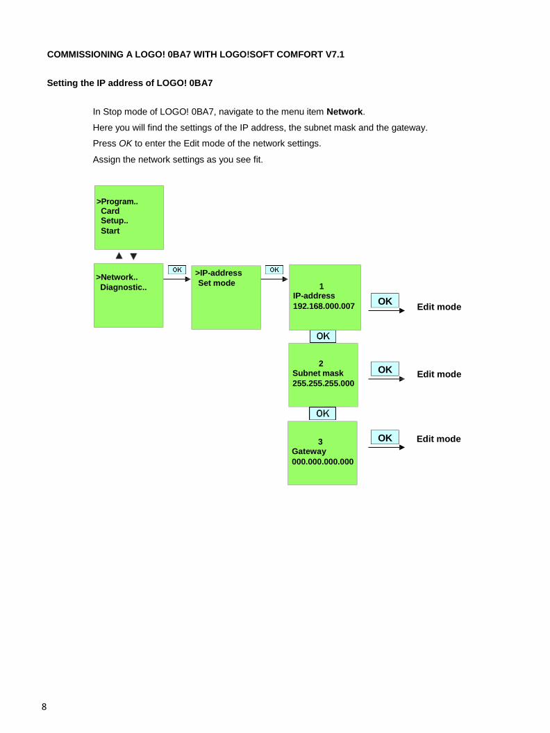
COMMISSIONING A LOGO! 0BA7 WITH LOGO!SOFT COMFORT V7.1
Setting the IP address of LOGO! 0BA7
In Stop mode of LOGO! 0BA7, navigate to the menu item Network.
Here you will find the settings of the IP address, the subnet mask and the gateway.
Press OK to enter the Edit mode of the network settings.
Assign the network settings as you see fit.
Edit mode
Edit mode
Edit mode
OK
OK
OK
>Program.. Card Setup.. Start
>Network.. Diagnostic..
>IP-address Set mode
1 IP-address 192.168.000.007
2 Subnet mask 255.255.255.000
3 Gateway 000.000.000.000

9
Setting the interface
Start the LOGO! SOFT Comfort V7.1 software.
Open the Tools menu and select Options.
LOGO! 0BA0 to 0BA6
Under interface, select the LOGO! cable with the COM interface

10
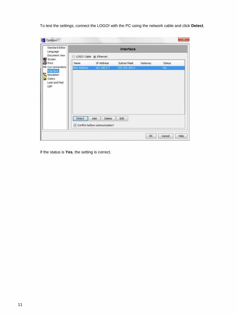
LOGO! 0BA7
Select Ethernet under Interface.
Click Add.
Enter the IP address and subnet mask.
11
To test the settings, connect the LOGO! with the PC using the network cable and click Detect.
If the status is Yes, the setting is correct.
12
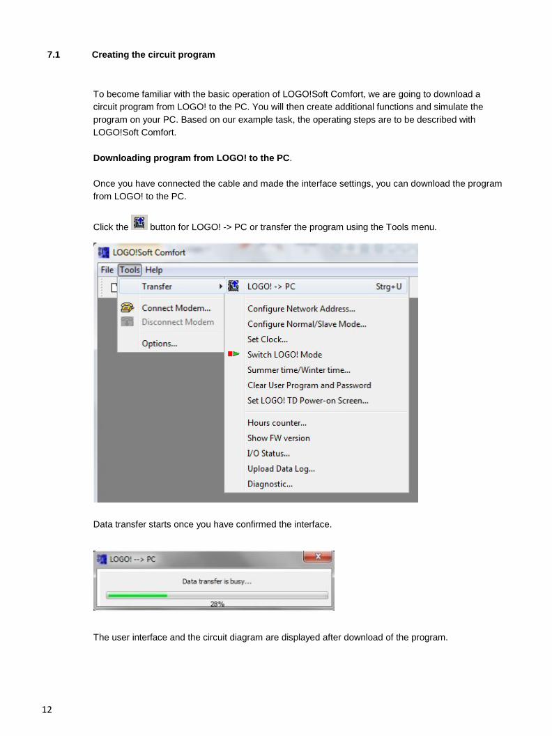
7.1 Creating the circuit program
To become familiar with the basic operation of LOGO!Soft Comfort, we are going to download a circuit program from LOGO! to the PC. You will then create additional functions and simulate the program on your PC. Based on our example task, the operating steps are to be described with LOGO!Soft Comfort.
Downloading program from LOGO! to the PC.
Once you have connected the cable and made the interface settings, you can download the program from LOGO! to the PC.
Click the button for LOGO! -> PC or transfer the program using the Tools menu.
Data transfer starts once you have confirmed the interface.
The user interface and the circuit diagram are displayed after download of the program.

13
COMMISSIONING A LOGO! 0BA8 WITH LOGO!SOFT COMFORT V8.0
Setting the IP address on LOGO! 0BA8
In Stop mode of LOGO! 0BA7, navigate to the menu item Network.
Here you will find the settings of the IP address, the subnet mask and the gateway.
Use the ► cursor or press OK to enter the Edit mode of the network settings.
Assign the network settings according to the specifications of your network administrator.
Note
In the rows with the ► or ▼ symbols, navigation by means of cursor keys is also possible.
LOGO!Soft Comfort V8.0
LOGO!Soft Comfort V8.0 provides a brand new user interface with the following features:
• Consistent application menu display
• New network project-based working approach
• Split display of diagram mode and network mode
• Split display for “Standard” toolbar in the general software interface, the “Tools” toolbar in diagram mode, and the “Network” toolbar in project mode
• Split window display with focus switching and drag-and-drop capabilities
• Ability to work on a network project with tasks of saving, loading, creating and closing the network project
• New access control settings to authorize online access with different access options
• Ability to create connections through configuring NI and NQ function blocks
• Ability to configure screen display for messages, power-on screen and flags with 4 lines for LOGO! devices prior to 0BA8 and 6 lines for LOGO! devices as of 0BA8
• Enhanced system security through setting user passwords and access levels through access control settings
IP - Address 192.168.000.001 Subnet Mask 255.255.255.000 Gateway 000.000.000.000
▼
▼ ▼
IP - Address Set M / S Mode
Start Program Setup Network Diagnostics Card
► ► ► ► ►

14
User interface of LOGO!Soft Comfort V8.0
Programming interface
LOGO!Soft Comfort programming mode starts with an empty circuit diagram.
The programming interface for creating your circuit programs occupies the greater part of the screen.
The icons and logical operations of the circuit program are arranged on this programming interface.
To help you to maintain an overview of large circuit programs, the right side and the bottom of the
programming interface contain scroll bars, which you can use for vertical and horizontal scrolling of
the circuit program.
Menu bar
Standard toolbar
Mode bar Programming toolbar
Programming interface Status bar
Diagram tree Instruction tree
15
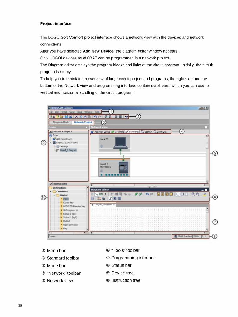
Project interface
The LOGO!Soft Comfort project interface shows a network view with the devices and network
connections.
After you have selected Add New Device, the diagram editor window appears.
Only LOGO! devices as of 0BA7 can be programmed in a network project.
The Diagram editor displays the program blocks and links of the circuit program. Initially, the circuit
program is empty.
To help you to maintain an overview of large circuit project and programs, the right side and the
bottom of the Network view and programming interface contain scroll bars, which you can use for
vertical and horizontal scrolling of the circuit program.
Menu bar Standard toolbar
Mode bar
“Network” toolbar Network view
“Tools” toolbar Programming interface
Status bar
Device tree Instruction tree

16
PROJECT PLANT GATE CONTROL WITH LOGO!SOFT COMFORT V8.0 AND LOGO! 0BA8
Starting LOGO!Soft Comfort V8.0 and adding LOGO! 0BA8
Start the LOGO!Soft Comfort V8.0 software.
The LOGO!Soft Comfort software opens in diagram mode.
Click the Network Project tab.
17
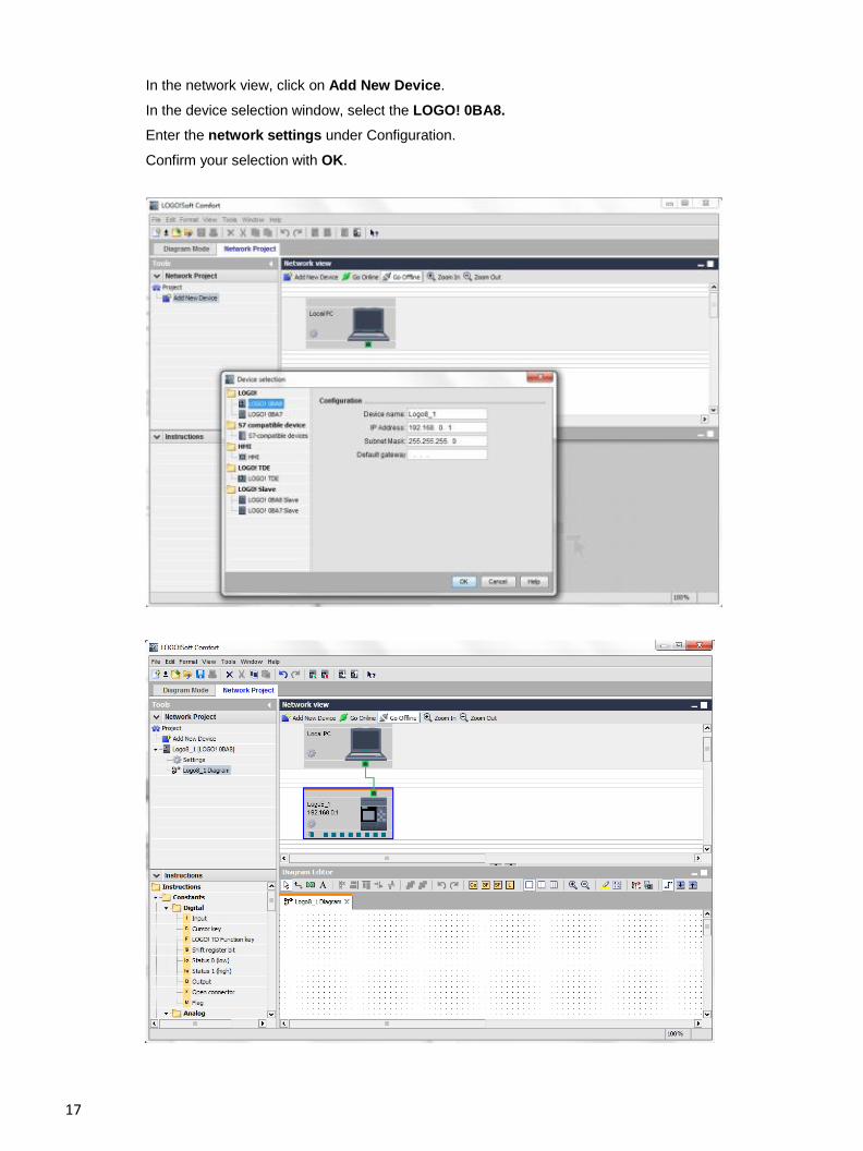
In the network view, click on Add New Device.
In the device selection window, select the LOGO! 0BA8. Enter the network settings under Configuration.
Confirm your selection with OK.

18
LOGO! 0BA8 settings
Open the LOGO! settings by double-clicking on Settings.
All offline/online settings of LOGO! 0BA8 can be edited here.