
SCDOT GEOPAK Drainage Manual for Roadway Design · · 2015-09-11GEOPAK Drainage Road Design...
57
SCDOT GEOPAK Drainage Manual for Roadway Design
Transcript of SCDOT GEOPAK Drainage Manual for Roadway Design · · 2015-09-11GEOPAK Drainage Road Design...

SCDOT GEOPAK Drainage Manual for Roadway Design

Introduction
GEOPAK Drainage Road Design Training Last printed 7/29/2015 4:09:00 PM Page 2
Introduction 3 Chapter 1: Data and Organization 4
1. File Types 4 2. Exchange of Information 7
- Generating Profiles 7 - Info to Hydrology 7 - Info from Hydrology 10
Chapter 2: Getting Started 12 1. Opening Drainage 12 2. Main Menu Bar 12 3. Configuration & Settings Files 12 4. Setting Preferences 13
Chapter 3: Drainage Navigator 14 1. Navigating 15 2. Updating Graphics 16 3. Updating Pay Items 17 4. Identifying Items 18
Chapter 4: Drafting 19 1. Driveway Pipes 19
- Start a Project 19 - Set the Preferences 19 - Add Nodes 21 - Add 1 Link 23 - Label Plans 24
2. Cross Section Files – Draw Side Line Pipes 25 3. Cross Section Files – Draw Cross Line Pipes 27 4. Drainage Structures in X-Section 29 5. Displaying 3D Networks 30
Chapter 5: Drainage Labeler 32 1. Labeler Setup 33
- Text Tab 34 - Params Tab 35 - Shape Tab 36 - Leader Tab 37 - Rotate Tab 38 - Styles Tab 39
2. Node Labeling 42 3. Link Labeling 44 4. Updating Labels 46 5. Label Tools 47
Chapter 6: Automated Quantities 48 1. Node Quantities 48 2. Link Quantities 50
Appendix A: Update Pay Items 53 Appendix B: Drainage Revisions 54 Appendix C: Error Messages 55

Introduction
GEOPAK Drainage Road Design Training Last printed 7/29/2015 4:09:00 PM Page 3
Introduction
This manual is designed for the Roadway division's usage of GEOPAK Drainage.
- Purpose
As all of us know, placing drainage onto a highway project is a time consuming process. In the past, Hydrology has provided to Road Design a red lined set of prints that has the drainage design drawn onto it. The drainage design was either labeled by hand on the red line set of prints or a computer printout providing the pipe sizes, flow line information, and box types was provided.
It was then the responsibility of the engineer in Road Design to place and label the drainage accurately on our plans. This process involves careful attention to detail when placing and labeling the drainage. It is our goal to help eliminate the potential for error when transferring the drainage design onto the plans, as well as to decrease the amount of time necessary to place and label the drainage design.
- Terminology
The following is a list of Geopak Drainage terminology.
Node – A node typically represents a drainage structure that has a point location. Examples include: catch basins, drop inlets, junction boxes, manholes, and points.
Link – A link represents a linear feature connecting two nodes, running from upstream to downstream. Examples include: pipes, ditches and channels.
Chapter 1: Data and Organization
GEOPAK Drainage Road Design Training Last printed 7/29/2015 4:09:00 PM Page 4
Chapter 1: Data and Organization 1. Files
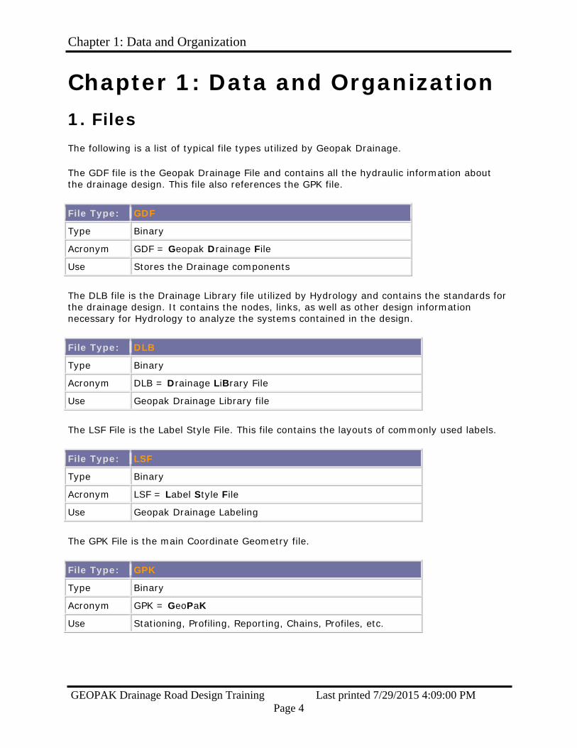
The following is a list of typical file types utilized by Geopak Drainage.
The GDF file is the Geopak Drainage File and contains all the hydraulic information about the drainage design. This file also references the GPK file.
File Type: GDF
Type Binary
Acronym GDF = Geopak Drainage File
Use Stores the Drainage components
The DLB file is the Drainage Library file utilized by Hydrology and contains the standards for the drainage design. It contains the nodes, links, as well as other design information necessary for Hydrology to analyze the systems contained in the design.
File Type: DLB
Type Binary
Acronym DLB = Drainage LiBrary File
Use Geopak Drainage Library file
The LSF File is the Label Style File. This file contains the layouts of commonly used labels.
File Type: LSF
Type Binary
Acronym LSF = Label Style File
Use Geopak Drainage Labeling
The GPK File is the main Coordinate Geometry file.
File Type: GPK
Type Binary
Acronym GPK = GeoPaK
Use Stationing, Profiling, Reporting, Chains, Profiles, etc.

Chapter 1: Data and Organization
GEOPAK Drainage Road Design Training Last printed 7/29/2015 4:09:00 PM Page 5
The pp.dgn file is the plan view of the project. The pp.dgn file will usually be named *#####pp.dgn. The * is either “r”, “m” or “c” and the ##### is the pin number. The .dgn is the designation for all Microstation design files.
File Type: PP.DGN
Type Binary
Acronym DGN = DesiGN
Use Plan View
The pf.dgn file is the plan and profile view of the project as it appears on the plan sheets. There will usually be more than one of these files for every project unless the project is very small.
File Type: PF.DGN
Type Binary
Acronym DGN = DesiGN
Use Plan & Profile View
The hy.dgn file is the Microstation file that is used by the Hydrology division.
File Type: HY.DGN
Type Binary
Acronym DGN = DesiGN
Use Microstation file for Geopak Drainage design
The Cell Library file is used by the Drainage division for placing Drainage Nodes into the HY.DGN file and for computing quantities.
File Type: *.CEL
Type Binary
Acronym CEL = CELL
Use Used for placing Node Cells
The Design & Computation Manager database file is used to compute drainage quantities.
File Type: *.DDB
Type Binary
Acronym DDB = Design DataBase
Use Used for computing quantities
Chapter 1: Data and Organization
GEOPAK Drainage Road Design Training Last printed 7/29/2015 4:09:00 PM Page 6
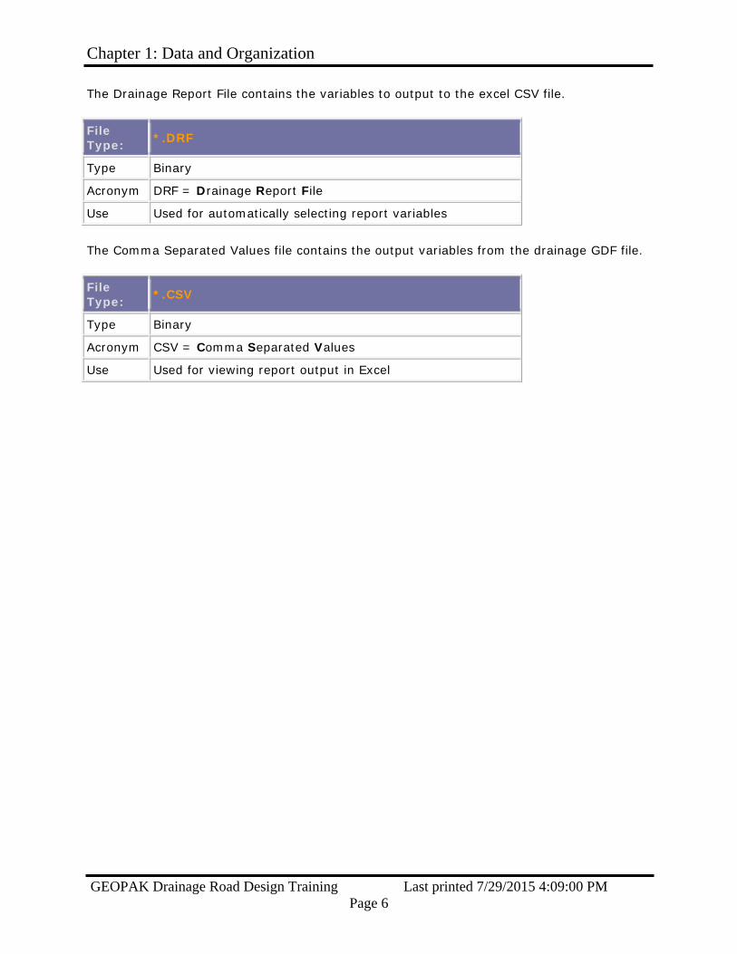
The Drainage Report File contains the variables to output to the excel CSV file.
File Type: *.DRF
Type Binary
Acronym DRF = Drainage Report File
Use Used for automatically selecting report variables
The Comma Separated Values file contains the output variables from the drainage GDF file.
File Type: *.CSV
Type Binary
Acronym CSV = Comma Separated Values
Use Used for viewing report output in Excel
Chapter 1: Data and Organization
GEOPAK Drainage Road Design Training Last printed 7/29/2015 4:09:00 PM Page 7
2. Exchange of Information
This section covers the transfer of information to and from Hydraulic Engineering.
- Generating Profiles
Hydrology requires profile information from Road Design before they can begin their design process. In addition to centerline profile grades, Hydrology will require top of curb profile grades and valley gutter profile grades early in our design process. Hydrology references our curb profile grades and valley gutter profile grades to design their drainage systems. In the future, Hydrology will be able to directly reference our shape files resulting in us not having to provide them curb grades and valley gutter grades.
It is important for Road Design to use a consistent naming symbology when generating curb profiles and valley gutter profiles. The following is an example of how to name these profiles to avoid confusion. Example: TCL93FP or VGR93FP
Section Type = TC or VG Location from Centerline = L or R Abbreviated Alignment Name = 93 (short for SC93) Future Profile = FP
- Info to Hydrology
Once the necessary profiles have been generated, you will then need to transfer the information to Hydrology. Hydrology requires the following information:
Hard Copy 1. Cross Sections to scale on half size sheets
a. Mainline b. Side roads c. Outfall ditches
2. Plan Sheets to scale on half size sheets a. Centerline final grades for mainline b. Final grades for side roads c. All outfall ditch surveys d. Limits of construction line e. All existing survey pipe recommendations
Electronic Copy
1. Project .GPK file 2. Project PP.DGN file 3. Project PF.DGN file 4. Project DX.DGN & FX.DGN files 5. Project .NEW file 6. Excel file containing survey data, including control points 7. Centerline and top of curb pgl’s. 8. Project curb grades

Chapter 1: Data and Organization
GEOPAK Drainage Road Design Training Last printed 7/29/2015 4:09:00 PM Page 8
The excel spreadsheet is a standard form that will be made available to everyone. This file contains detailed descriptions of COGO chain names, profiles, pp.dgn file name, pf.dgn file names, the server location of project files, as well as other important information. The file should be named as follows: Example: R21686.xls
English or Metric = R or M Pin Number = 21686
The following page is a printout of what the excel spreadsheet looks like. The gray areas contain information to be edited for each project. ROAD DESIGN DATA FOR HYDRAULIC DESIGN DATE: 8/18/2008
DESIGN GROUP: RPG 4 - UPSTATE
PIN NO.: 36298
COUNTY: OCONEE
ROAD/ROUTE NO.: S-402 / SHEEPFARM RD.
PROJECT DESCRIPTION:
WIDEN (SHEEPFARM RD.) EXISTING 2 LANES TO 5 LANE CURB & GUTTER WITH BIKE LANES AND SIDEWALKS ON BOTH SIDES. CONNECT SHEEPFARM ROAD TO SC 28 (BLUE RIDGE BLVD.) WITH NEW LOCATION STARTING AT S-135 (BOUNTYLAND ROAD).
ADDITIONAL NOTES: S-135 WILL BE WIDENED TO 5 LANE CURB & GUTTER AT THE INTERSECTION WITH SHEEPFARM ROAD. IT WILL THEN TIE BACK TO THE EXISTING PAVEMENT. STONEBROOK DRIVE WILL HAVE A VALLEY GUTTER. ALL OTHER SIDE ROADS WILL HAVE DITCH SECTIONS.
FILE INFORMATION SERVER DESIGN GROUP COUNTY PIN
FILES LOCATED: NTS/HQ/Precon/ RPG 4 OCONEE 36298
'.GPK' FILE(S): JOB298.GPK
'PP' FILE(S): R36298PP.DGN
'PF' FILE(S) R36298PF1.DGN S-402 (SHTS. 6 - 13)
R36298PF2.DGN SIDE ROADS (SHTS. 14 -
23)
R36298PF3.DGN SIDE ROADS (SHTS. 24 -
26)

Chapter 1: Data and Organization
GEOPAK Drainage Road Design Training Last printed 7/29/2015 4:09:00 PM Page 9
'.NEW' FILE(S): 36298.NEW 36298A.NEW
CHAIN NAME PROPOSED
PROFILE DESCRIPTION S402REL S402RFP CENTER LINE GRADE S-402 RELOCATION
US76 CENTER LINE US 76 BROOKLANER BROOKLANERFP CENTER LINE GRADE BROOK LN. REL.
STONEBROOKR STONEBROOKRFP CENTER LINE GRADE STONEBROOK DR. REL. S135REL S135RFP CENTER LINE GRADE S-135 RELOCATION
SPRINGWOOD CENTER LINE EAST SPRINGWOOD DR. OCONEER1 OCONEER1FP CL GRADE OCONEE ESTATES REL. PART 1 OCONEER2 OCONEER2FP CL GRADE OCONEE ESTATES REL. PART 2 ALBERTSR ALBERTSRFP CENTER LINE GRADE ALBERT'S RD. REL. PAULGILLR PAULGILLRFP CENTER LINE GRADE PAUL GILLISON RD. REL.
SC28 CENTER LINE SC 28 TANGLEWOOD CENTER LINE TANGLEWOOD DR.
STREAM1 CENTER LINE OF STREAM #1 STREAM2 CENTER LINE OF STREAM #2 STREAM3 CENTER LINE OF STREAM #3 STREAM4 CENTER LINE OF STREAM #4 STREAM5 CENTER LINE OF STREAM #5 STREAM6 CENTER LINE OF STREAM #6
CHAIN NAME CROSS SECTIONS DESCRIPTION
S402REL S402REL_DX_SCALED.DGN STA. 10+00.00 - 114+64.38 US76 US76DX.DGN STA. 10+50.00 - 20+00.00
BROOKLANER BROOKLANERDX_SCALED.DGN STA. 10+35.87 - 16+27.98 STONEBROOKR STONEBROOKRDX_SCALED.DGN STA. 10+35.92 - 15+94.48
S135REL S135RDX_SCALED.DGN STA. 10+00.00 - 42+79.57 SPRINGWOOD SPRINGWOODDX.DGN STA. 10+12.71 - 15+57.93
OCONEER1 OCONEER1DX_SCALED.DGN STA. 10+30.38 - 16+00.00 OCONEER2 OCONEER2DX_SCALED.DGN STA. 36+00.00 - 41+26.31 ALBERTSR ALBERTSRDX_SCALED.DGN STA. 7+00.00 - 12+22.35 PAULGILLR PAULGILLRDX_SCALED.DGN STA. 15+02.15 - 19+01.89
SC28 SC28DX.DGN STA. 648+00.00 - 660+00.00 TANGLEWOOD

Chapter 1: Data and Organization
GEOPAK Drainage Road Design Training Last printed 7/29/2015 4:09:00 PM Page 10
- Info from Hydrology
When Hydrology completes their drainage design, they will send you an excel spreadsheet containing information necessary for you to understand their drainage design. This spreadsheet will contain the server location of their files, the name of the gdf file, the name of the dlb file, as well as other important information.
The following is a printout of what the excel spreadsheet from Hydrology will look like: HYDRAULIC DESIGN DATA FOR ROAD DESIGN
DATE :
HYDRO SQUAD: VAUGHAN
PIN NO.: 21686
COUNTY: ABBEVILLE
ROAD/ROUTE NO.: SC-72
PROJECT
DESCRIPTION: THIS AREA WILL BE USED TO DESCRIBE THE PROJECT
ADDITIONAL NOTES: THIS SPACE WILL BE USED FOR ANY ADDITIONAL
FILE INFORMATION SMPSERV6 \ HYDRO
SQD\ COUNTY \ PIN
FILES LOCATED: SMPSERV6 \ VAUGHAN \ ABBEVILLE \ 21686
'.GDF' FILE: SC93.GDF
'.DLB' FILE:
EXCEL' FILE(S)
Chapter 1: Data and Organization
GEOPAK Drainage Road Design Training Last printed 7/29/2015 4:09:00 PM Page 11
In addition to receiving the spreadsheet from Hydrology, we will also receive the following information: Hard Copy
1. Plan sheets stating which existing pipes are to be abandoned or retained. Electronic Copy
1. Project .GDF file 2. Project .DLB Drainage Library file (if modified for project exceptions) 3. Project HY.DGN file 4. Proposed ditch cross sections 5. Alternate Pipe spreadsheet 6. Erosion Control Data Sheet 7. Additional erosion control BMP recommendations as appropriate
.

Chapter 2: Getting Started
GEOPAK Drainage Road Design Training Last printed 7/29/2015 4:09:00 PM Page 12
Chapter 2: Getting Started 1. Opening Drainage
The location and names of the files you will need for the drainage design are on the spreadsheet you received from Hydrology.
Before opening Drainage use the following steps:
1. Copy the GDF File and (if received) the DLB File to the project directory on your machine; you are now ready to begin using GEOPAK Drainage.
2. Open the pp.dgn file for the project.
2. Main Menu Bar
The Drainage Menu Bar is initiated from the Applications pull-down menu, remains open while Drainage is open, and can be docked:
The Menu Bar always displays the GDF file name (shown above in yellow ) and the Active Network (shown above in red ).
To open the Drainage file:
1. Use the Drainage menu bar shown above and select Project>Open and select the GDF File from the project directory.
2. Ignore any Warning Messages (if any) for now.
3. Configuration & Settings Files Geopak Drainage by default will select configuration files, but a good rule of thumb is to use the same dlb, cel library & ddb files that the hydraulic designer used in creating their systems. These are usually found in the projects hydro folder or by asking the designer for help in their location. Care should be taken to ensure that the correct workspace is utilized.

Chapter 2: Getting Started
GEOPAK Drainage Road Design Training Last printed 7/29/2015 4:09:00 PM Page 13
4. Setting Preferences
Select Project>Preferences and set the Project Components as shown below:
1. Select the DLB File from the project Hydro folder as used by the Hydraulic Designer 2. Select the correct GPK File. 3. Check the Road Preferences to make sure everything is properly setup 4. Select RoadV8.cel for your Drainage Cell Library 1. Select scdot_engV8.ddb as your Geopak ddb file 2. Select OK when finished.
Navigating
GEOPAK Drainage Road Design Training Last printed 7/29/2015 4:09:00 PM Page 14
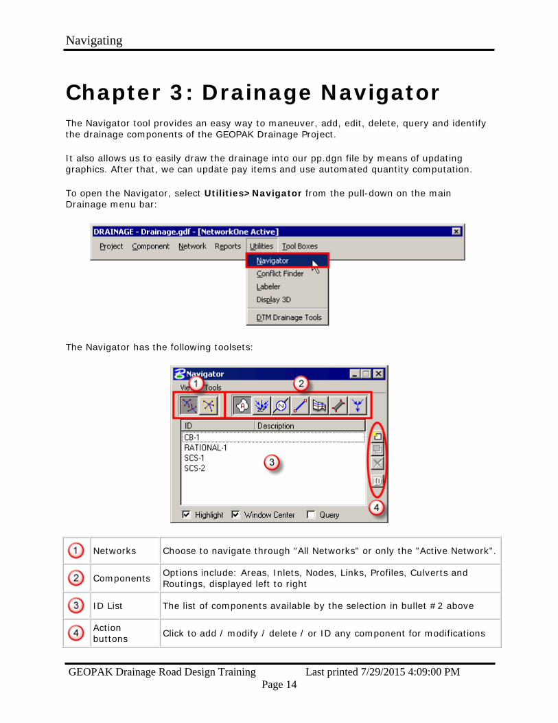
Chapter 3: Drainage Navigator The Navigator tool provides an easy way to maneuver, add, edit, delete, query and identify the drainage components of the GEOPAK Drainage Project.
It also allows us to easily draw the drainage into our pp.dgn file by means of updating graphics. After that, we can update pay items and use automated quantity computation.
To open the Navigator, select Utilities>Navigator from the pull-down on the main Drainage menu bar:
The Navigator has the following toolsets:
Networks Choose to navigate through "All Networks" or only the "Active Network".
Components Options include: Areas, Inlets, Nodes, Links, Profiles, Culverts and
Routings, displayed left to right
ID List The list of components available by the selection in bullet #2 above
Action buttons Click to add / modify / delete / or ID any component for modifications

Navigating
GEOPAK Drainage Road Design Training Last printed 7/29/2015 4:09:00 PM Page 15
1. Navigating
The Navigator window allows you to click through the lists of drainage objects to identify and modify the components you are interested in.
Type Select the component type of interest – only that type will be shown in
the components list.
Toggles Toggle ON so the Microstation view will highlight and center on a
drainage component when it is selected.
Component Click any component in the list.
View The Microstation view updates to window center and highlight the
selected drainage component.
Repeat as necessary to navigate the components

Navigating
GEOPAK Drainage Road Design Training Last printed 7/29/2015 4:09:00 PM Page 16
2. Updating Graphics
To update the Drainage graphics in the PP.DGN file, follow the steps below:
Type Select the component type of interest
Selection Select all (or any you wish) components in the list for graphical
updating
Tools Select Tools > Update Graphics to commence the procedure
View The Microstation view updates with the revised graphics.
Repeat as necessary to update the graphics on the components.

Navigating
GEOPAK Drainage Road Design Training Last printed 7/29/2015 4:09:00 PM Page 17
3. Updating Pay Items
To update the Drainage graphics in the PP.DGN file according to the symbology in the DDB file, in order to compute quantities, follow the steps below:
Type Select the component type of interest
Selection Select all (or any you wish) components in the list for Pay Item updating
Tools Select Tools > Update Pay Items to commence the procedure
View The Microstation view updates with the revised Pay Items
Repeat as necessary to update the Pay Items on the components
Links will be on level "RD_PD_DR_Pipe" with a custom line style of PIPE NEW1; the nodes will be on level "RD_PD_DR_Inlet" with the proper cell.

Navigating
GEOPAK Drainage Road Design Training Last printed 7/29/2015 4:09:00 PM Page 18
4. Identifying Items
Navigator can also be used to identify a drainage component from its graphic in the Microstation file.
Type Select the component type of interest.
ID Click the ID button
Select Select any Node or Link in the DGN file
Navigator Notice the specific Node or Link gets found and highlighted in the
Navigator window
Repeat as necessary to identify the drainage components.

Chapter 4: Drafting
GEOPAK Drainage Road Design Training Last printed 7/29/2015 4:09:00 PM Page 19
Chapter 4: Drafting
1. Driveway Pipes
The following procedures are used to draw, label, and report on drive pipes or cross pipes.
- Start a Project
To start a new Drainage Project:
1. Open the Microstation DGN file. 2. From Microstation, select Applications>GEOPAK DRAINAGE>Drainage (if GEOPAK is
not activated select Applications>GEOPAK>Activate GEOPAK). 3. You should now have a new menu item by Applications titled Drainage. 4. Selecting Drainage>Project>Save As… Name the file after the driveways pipes or
cross pipes being improved.
GEOPAK Drainage always starts in an untitled project; it does not remember or automatically reopen a GDF that was previously worked in. The .GDF file must be reopened
manually each time you open the DGN file. Select Project > Open each time you start to edit or continue working on a project.
- Set the Preferences
Set the Preferences; from the main Drainage menu bar Project > Preferences:

Chapter 4: Drafting
GEOPAK Drainage Road Design Training Last printed 7/29/2015 4:09:00 PM Page 20
Set the Project Components as shown below:
DLB Click on the magnifying glass button and select the DLB file
GPK
Click the magnifying glass button and select the GPK Job Number. You need to select your project directory and choose the file job###.gpk; there should only be one .gpk file. When you choose OK only the 3-digit number that was in the file name appears.
CEL Click the magnifying glass and select the roadv8.cel file in the workspace folder.
DDB Click the magnifying glass and select the scdot_engV8.ddb file in the workspace
location.

Chapter 4: Drafting
GEOPAK Drainage Road Design Training Last printed 7/29/2015 4:09:00 PM Page 21
- Add Nodes To add nodes go to Drainage>Component>Node>Add. The "Add a New Node" dialog will open for each Node asking for a Node name prefix and number. The number automatically increases for each node up to 10000. These instructions will place the upstream node for the pipe. Repeat them for the downstream node when you are through.
Set the Properties Options:
Node Type Set to "Other"
Library Item Set to "DUMMY JOINT"
Apply Click the Apply button to accept the Properties.

Chapter 4: Drafting
GEOPAK Drainage Road Design Training Last printed 7/29/2015 4:09:00 PM Page 22
Set the Location Option:
Chain
Use the pulldown arrow to select the correct chain name. This information comes from the GPK File. If you are placing a node on a side road make sure to use the corresponding side road chain name. Turn off the curb profile option for dummy nodes.
Station DP Click the Station DP button, move the cursor to place the upstream dummy
joint at the upstream entrance of the driveway pipe.
Apply Click the Apply button to accept the Location.
Chapter 4: Drafting
GEOPAK Drainage Road Design Training Last printed 7/29/2015 4:09:00 PM Page 23
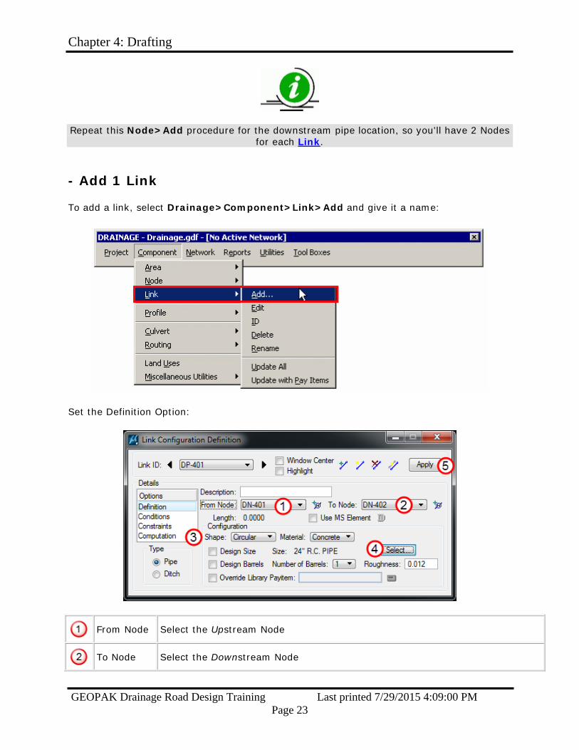
Repeat this Node>Add procedure for the downstream pipe location, so you'll have 2 Nodes for each Link.
- Add 1 Link
To add a link, select Drainage>Component>Link>Add and give it a name:
Set the Definition Option:
From Node Select the Upstream Node
To Node Select the Downstream Node

Chapter 4: Drafting
GEOPAK Drainage Road Design Training Last printed 7/29/2015 4:09:00 PM Page 24
Shape/ Material
Set the Shape to "Circular" and the Material to the appropriate type from the Drainage Library
Design Size Toggle OFF, and click Select to pick the size from the Drainage Library
Apply Click Apply to accept the Pipe Definition.
Continue adding Nodes and Links for the rest of the driveway or cross pipes.
- Label Plans
The plans are now ready to be labeled using the Drainage Labeler.
Since only a few Node and Link variables were set, only certain label variables will be available for driveway or cross pipes.

Chapter 4: Drafting
GEOPAK Drainage Road Design Training Last printed 7/29/2015 4:09:00 PM Page 25
2. Cross Section Files – Draw Side Line Pipes Open the *dx.dgn design file and select Applications -> GEOPAK -> ROAD -> Design & Computation Manager from the menu bar.
Select English -> VBA Applications -> XS Pipes and double click to start the macro.
On the General tab, select the Job and Chain, then browse to select the *.gdf file in the project folder. Check on the Honor XS Exaggeration. (This toggle controls the size of the pipe drawn on the cross sections in case they are drawn 10:5 vs. 5:5).

Chapter 4: Drafting
GEOPAK Drainage Road Design Training Last printed 7/29/2015 4:09:00 PM Page 26
On the Side-Line Pipes tab, accept the defaults and press the Process Cross Sections button. (You can change the symbology by clicking the appropriate buttons prior to processing as well.)
Press the Begin button and wait for the program to finish. Select Yes to save a *.csv pipe report file. Pipe drawings in cross sections should be reviewed by roadway and hydraulic engineers after processing.

Chapter 4: Drafting
GEOPAK Drainage Road Design Training Last printed 7/29/2015 4:09:00 PM Page 27
3. Cross Section Files – Draw Cross Line Pipes Open a plan view .dgn file showing the cross line pipes. Draw drainage pattern lines along each cross line pipe using Microstation “draw line” command. Pattern lines should be set to one of the RD_PD_PatLn# levels and should extend a minimum of 20 feet beyond each end of the cross line pipe or to the construction limits.
Alternatively, open the D&C Manager (Applications -> GEOPAK -> ROAD -> Design & Computation Manager on the menu bar), select English -> VBA Applications -> Drainage Patterns, and double click to start the macro.
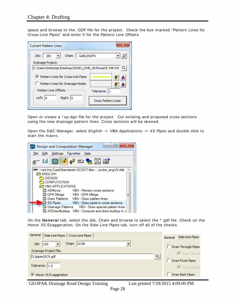
In the Culvert Pattern Lines window, enter the Job number of the project and select the chain of the road being crossed. Click the magnifying glass next to the “Drainage Project”
Chapter 4: Drafting
GEOPAK Drainage Road Design Training Last printed 7/29/2015 4:09:00 PM Page 28
space and browse to the .GDF file for the project. Check the box marked “Pattern Lines for Cross-Line Pipes” and enter 0 for the Pattern Line Offsets
Open or create a *xp.dgn file for the project. Cut existing and proposed cross sections using the new drainage pattern lines. Cross sections will be skewed. Open the D&C Manager, select English -> VBA Applications -> XS Pipes and double click to start the macro.
On the General tab, select the Job, Chain and browse to select the *.gdf file. Check on the Honor XS Exaggeration. On the Side-Line Pipes tab, turn off all of the checks.
Chapter 4: Drafting
GEOPAK Drainage Road Design Training Last printed 7/29/2015 4:09:00 PM Page 29
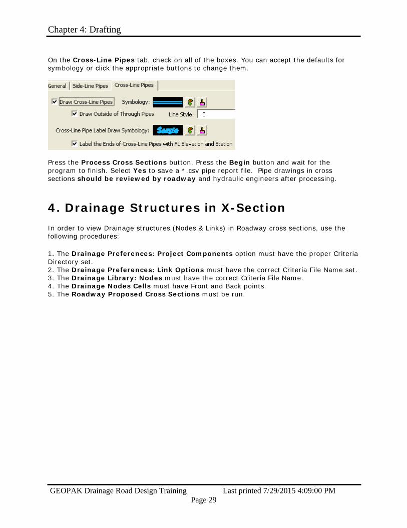
On the Cross-Line Pipes tab, check on all of the boxes. You can accept the defaults for symbology or click the appropriate buttons to change them.
Press the Process Cross Sections button. Press the Begin button and wait for the program to finish. Select Yes to save a *.csv pipe report file. Pipe drawings in cross sections should be reviewed by roadway and hydraulic engineers after processing.
4. Drainage Structures in X-Section
In order to view Drainage structures (Nodes & Links) in Roadway cross sections, use the following procedures:
1. The Drainage Preferences: Project Components option must have the proper Criteria Directory set. 2. The Drainage Preferences: Link Options must have the correct Criteria File Name set. 3. The Drainage Library: Nodes must have the correct Criteria File Name. 4. The Drainage Nodes Cells must have Front and Back points. 5. The Roadway Proposed Cross Sections must be run.

Chapter 4: Drafting
GEOPAK Drainage Road Design Training Last printed 7/29/2015 4:09:00 PM Page 30
5. Displaying 3-D Networks Create a new 3-D .dgn. Start GEOPAK Drainage and open the .gdf containing the network. Open the GEOPAK Drainage Preferences menu and go to the Project Components tab. Ensure that the Drainage Cell Library being used is the most up-to-date RoadV8.cel dated 8/24/2011 or later. If not, load the *.dpf file associated with the project and check again. Update all Nodes and Links via Navigator.
Activate the 3D display using Utilities -> Display 3D in the Drainage menu. Change the Display Style in View Attributes from “Wireframe” to “Smooth.”

Chapter 4: Drafting
GEOPAK Drainage Road Design Training Last printed 7/29/2015 4:09:00 PM Page 31
A 3-D representation of the network will be drawn above the existing 2-D version. Use the Rotate View tool in the View menu to observe the network from other angles.
A 3-D view can reveal errors in the network design, such as incorrect structure and pipe elevations. Examining this view for pieces that appear out of place or incorrectly shaped can be much quicker than comparing the data associated with each pipe and node in text format using the Navigator tool.

Chapter 5: Drainage Labeler
GEOPAK Drainage Road Design Training Last printed 7/29/2015 4:09:00 PM Page 32
Chapter 5: Drainage Labeler
GEOPAK Drainage Labeler automates the composition and placement of drainage notes onto drawings. The label is composed of inserts that the user controls. These inserts can be customized to form labels. Several standard label styles are provided in order to label pipes and inlets.
Step 1. From the main menu bar, select Utilities > Labeler:
Step 2. First click the Styles Tab; then Select Style Files > Open... and open the \\nts\hq\CaddStandards\SCDOT-Bentley\Standards\SCDOT_Design\Geofiles\Labelers\scdot.LSF.
Chapter 5: Drainage Labeler
GEOPAK Drainage Road Design Training Last printed 7/29/2015 4:09:00 PM Page 33
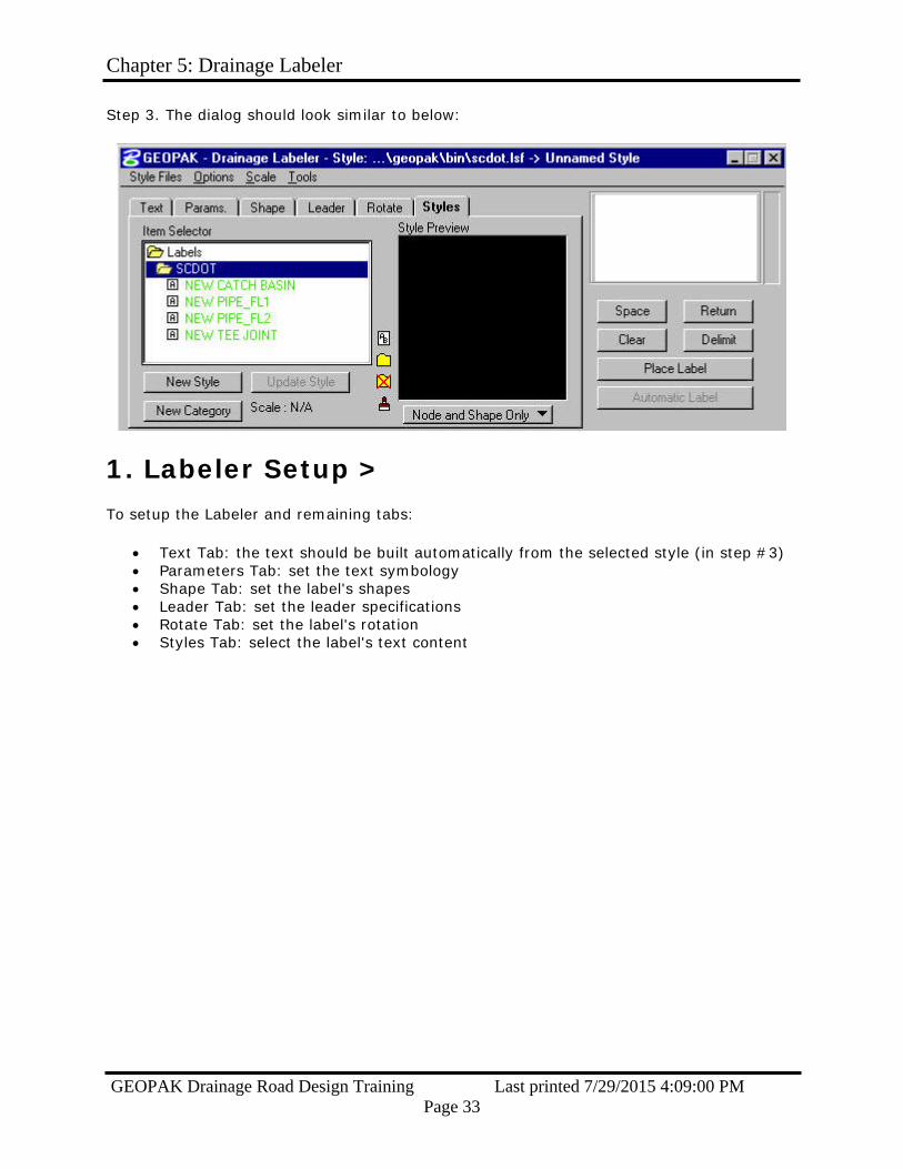
Step 3. The dialog should look similar to below:
1. Labeler Setup >
To setup the Labeler and remaining tabs:
Text Tab: the text should be built automatically from the selected style (in step #3) Parameters Tab: set the text symbology Shape Tab: set the label's shapes Leader Tab: set the leader specifications Rotate Tab: set the label's rotation Styles Tab: select the label's text content

Chapter 5: Drainage Labeler
GEOPAK Drainage Road Design Training Last printed 7/29/2015 4:09:00 PM Page 34
- Text Tab
If the text is different from the stored style, set the label's text content as shown below:
Element ID Select the Type of component and then the Element ID.
Computed Text Single-click on the computed text of interest
Read-Only View the read-only computed text readout (shown in bold), and set
the # of decimals (if available)
Computed Text Double-click on the computed text to place it (bullet #5)
Label Window After double-clicking the computed text (bullet #4) the text is inserted
into the label window at the cursor's location in the window
Prefix & Suffix
(Optional) Use keyboard text to add prefixes and/or suffixes to the Computed Text (bullet #5) but not inside the computed text itself (as breaking inside the computed text breaks the auto computed text)
Chapter 5: Drainage Labeler
GEOPAK Drainage Road Design Training Last printed 7/29/2015 4:09:00 PM Page 35
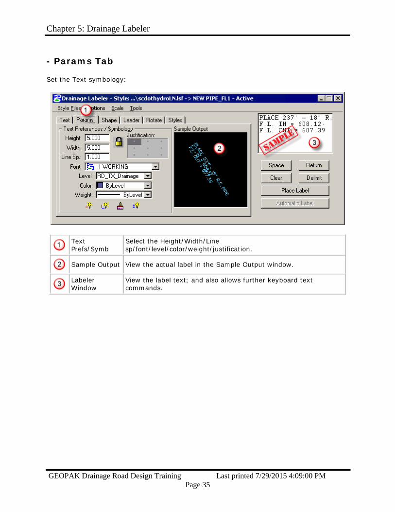
- Params Tab
Set the Text symbology:
Text Prefs/Symb
Select the Height/Width/Line sp/font/level/color/weight/justification.
Sample Output View the actual label in the Sample Output window.
Labeler Window
View the label text; and also allows further keyboard text commands.
Chapter 5: Drainage Labeler
GEOPAK Drainage Road Design Training Last printed 7/29/2015 4:09:00 PM Page 36
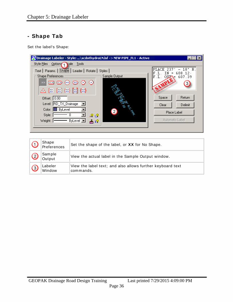
- Shape Tab
Set the label's Shape:
Shape Preferences Set the shape of the label, or XX for No Shape.
Sample Output View the actual label in the Sample Output window.
Labeler Window
View the label text; and also allows further keyboard text commands.
Chapter 5: Drainage Labeler
GEOPAK Drainage Road Design Training Last printed 7/29/2015 4:09:00 PM Page 37
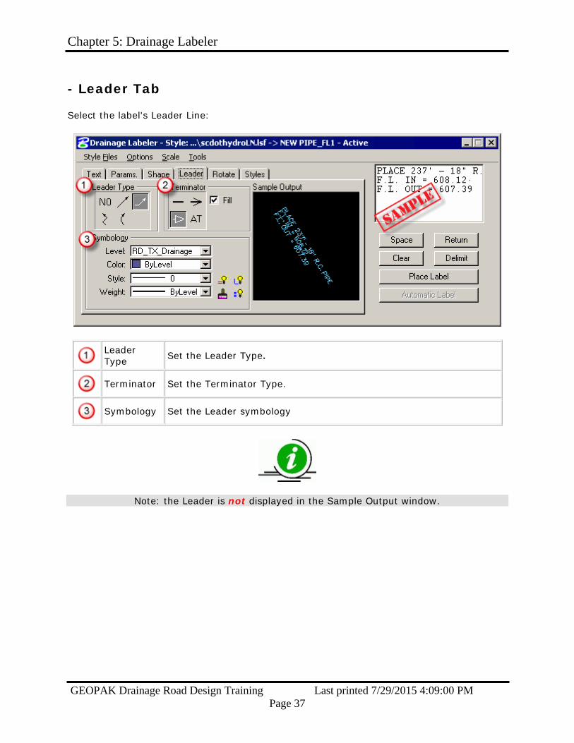
- Leader Tab
Select the label's Leader Line:
Leader Type Set the Leader Type.
Terminator Set the Terminator Type.
Symbology Set the Leader symbology
Note: the Leader is not displayed in the Sample Output window.
Chapter 5: Drainage Labeler
GEOPAK Drainage Road Design Training Last printed 7/29/2015 4:09:00 PM Page 38
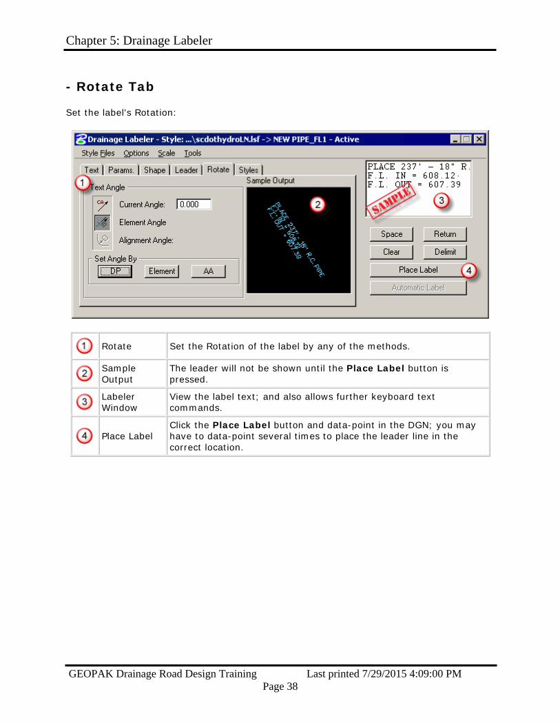
- Rotate Tab
Set the label's Rotation:
Rotate Set the Rotation of the label by any of the methods.
Sample Output
The leader will not be shown until the Place Label button is pressed.
Labeler Window
View the label text; and also allows further keyboard text commands.
Place Label
Click the Place Label button and data-point in the DGN; you may have to data-point several times to place the leader line in the correct location.

Chapter 5: Drainage Labeler
GEOPAK Drainage Road Design Training Last printed 7/29/2015 4:09:00 PM Page 39
- Styles Tab
The Styles Tab is where the individual Styles are stored, displayed and retrieved.
Options include:
Style: Adding: add new styles Style: Updating: modify existing styles Style: Categories: add new styles category
You must be on the Styles Tab to utilize the StyleFiles pull-down menu.
To add a Style:
Item Selector Select the Category (folder icon) in which to place the Style.
Save the Style Click the New Style button to save the Label Style.
1. You must first use the Place Label button before the label can be saved as a Style. 2. Use Styles whenever possible so that the Label Updater can update the labels.

Chapter 5: Drainage Labeler
GEOPAK Drainage Road Design Training Last printed 7/29/2015 4:09:00 PM Page 40
To update a Style:
Item Selector
First activate a Style, then make changes to any of the Tabs (Text, Params, Shape, Leader, or Rotate); then place the New Label in the DGN File.
Update the Style Click Update Style to update the Label Style.
1. You must first use the Place Label button before the label can be saved as a Style. 2. Use Styles whenever possible so that the Label Updater can update the labels.
3. When complete (or periodically) select File > Save from the StyleFiles pulldown menu (must be on the Styles Tab to do this).
Chapter 5: Drainage Labeler
GEOPAK Drainage Road Design Training Last printed 7/29/2015 4:09:00 PM Page 41
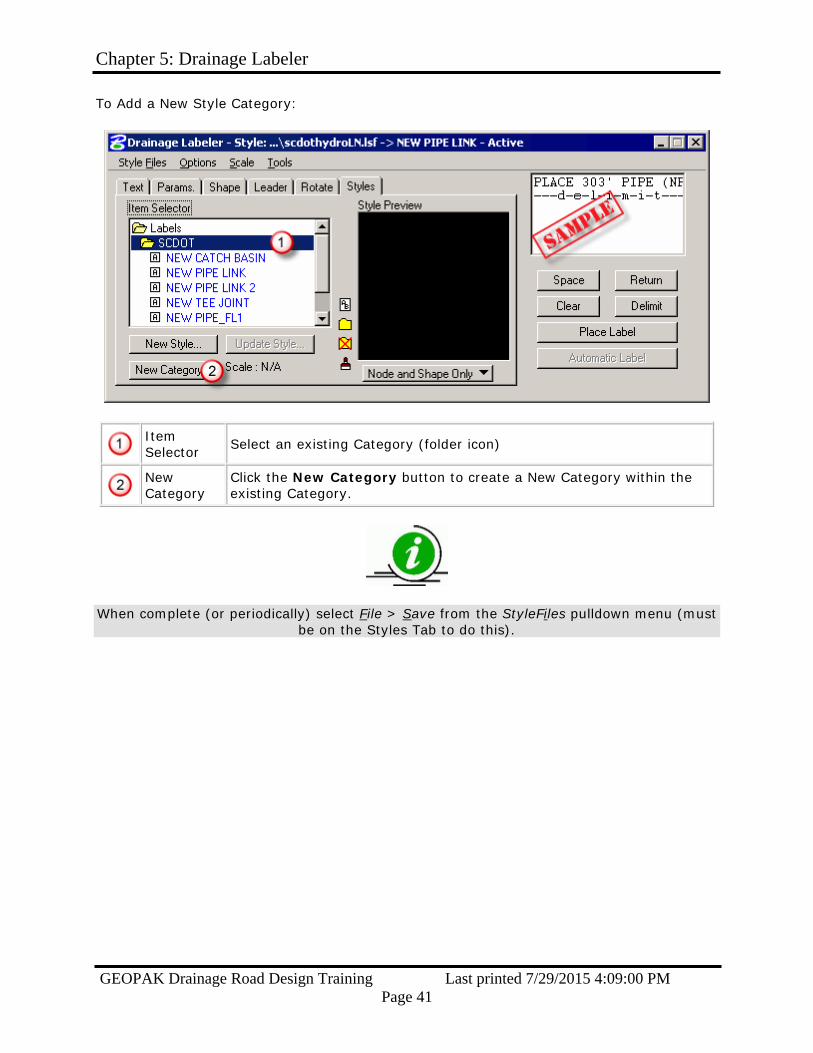
To Add a New Style Category:
Item Selector Select an existing Category (folder icon)
New Category
Click the New Category button to create a New Category within the existing Category.
When complete (or periodically) select File > Save from the StyleFiles pulldown menu (must be on the Styles Tab to do this).

Chapter 5: Drainage Labeler
GEOPAK Drainage Road Design Training Last printed 7/29/2015 4:09:00 PM Page 42
2. Node Labeling
When labeling nodes using the following workflow:
Step 1. Select and activate a label:
Double-click the Item Selector to find the Label you wish to place.
Click the check mark, which will activate the style, and place it in the label window
Step 2. Select the Text Tab and then highlight a Drainage Node to label:
Chapter 5: Drainage Labeler
GEOPAK Drainage Road Design Training Last printed 7/29/2015 4:09:00 PM Page 43
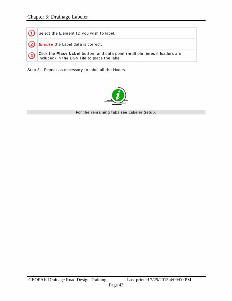
Select the Element ID you wish to label.
Ensure the Label data is correct.
Click the Place Label button, and data point (multiple times if leaders are included) in the DGN File to place the label.
Step 3. Repeat as necessary to label all the Nodes.
For the remaining tabs see Labeler Setup.
Chapter 5: Drainage Labeler
GEOPAK Drainage Road Design Training Last printed 7/29/2015 4:09:00 PM Page 44
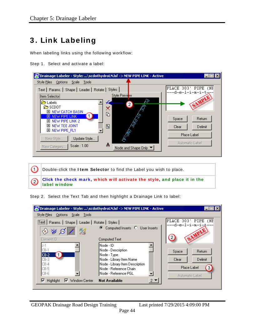
3. Link Labeling
When labeling links using the following workflow:
Step 1. Select and activate a label:
Double-click the Item Selector to find the Label you wish to place.
Click the check mark, which will activate the style, and place it in the label window
Step 2. Select the Text Tab and then highlight a Drainage Link to label:

Chapter 5: Drainage Labeler
GEOPAK Drainage Road Design Training Last printed 7/29/2015 4:09:00 PM Page 45
Select the Element ID you wish to label.
Ensure the Label data is correct.
Click the Place Label button, and data point (multiple times if leaders are included) in the DGN File to place the label.
Step 3. Repeat as necessary to label all the Links.
For the remaining tabs see Labeler Setup.

Chapter 5: Drainage Labeler
GEOPAK Drainage Road Design Training Last printed 7/29/2015 4:09:00 PM Page 46
4. Updating Labels
Auto-Computed Labels can be automatically updated. From the Labeler pull-down menu, select Tools > Label Updater:
Use the workflow shown below:
Click on All Labels (or choose individual labels, or labels within a Microstation selection set)
Select the constraint for which labels will Highlight, then click Highlight, the plan view labels matching the constraint will highlight in the DGN.
Click the Start button to initiate updating, and then use the Skip, Update Label, or Update All buttons to select which labels will be updated.
Chapter 5: Drainage Labeler
GEOPAK Drainage Road Design Training Last printed 7/29/2015 4:09:00 PM Page 47
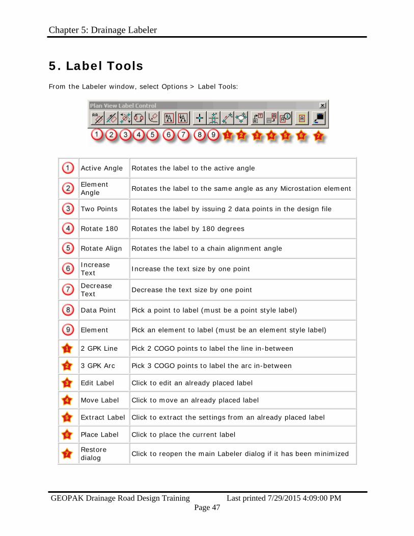
5. Label Tools
From the Labeler window, select Options > Label Tools:
Active Angle Rotates the label to the active angle
Element Angle Rotates the label to the same angle as any Microstation element
Two Points Rotates the label by issuing 2 data points in the design file
Rotate 180 Rotates the label by 180 degrees
Rotate Align Rotates the label to a chain alignment angle
Increase Text Increase the text size by one point
Decrease Text Decrease the text size by one point
Data Point Pick a point to label (must be a point style label)
Element Pick an element to label (must be an element style label)
2 GPK Line Pick 2 COGO points to label the line in-between
3 GPK Arc Pick 3 COGO points to label the arc in-between
Edit Label Click to edit an already placed label
Move Label Click to move an already placed label
Extract Label Click to extract the settings from an already placed label
Place Label Click to place the current label
Restore dialog Click to reopen the main Labeler dialog if it has been minimized

Chapter 6: Automated Quantities
GEOPAK Drainage Road Design Training Last printed 7/29/2015 4:09:00 PM Page 48
Chapter 6: Automated Quantities See the sections below for computing Node and Link quantities.
1. Node Quantities Step 1. From the main menu bar, select Component > Node > Update with Pay Items:
Update individual Node Items by selecting the individual Nodes in the Navigator, then using the Navigator's pull-down menu, select, Tools > Update Pay Items.
Step 2. Open the D&C Manager:

Chapter 6: Automated Quantities
GEOPAK Drainage Road Design Training Last printed 7/29/2015 4:09:00 PM Page 49
Step 3. Set the dialog using the workflow shown below:
Click Compute
Select
Category Navigate to the Drainage Structures category
Click Add to Selection
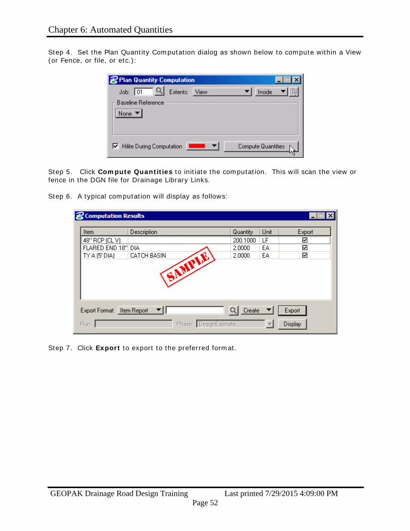
Step 4. Set the Plan Quantity Computation dialog as shown below to compute within a View (or Fence, or file, or etc.):

Chapter 6: Automated Quantities
GEOPAK Drainage Road Design Training Last printed 7/29/2015 4:09:00 PM Page 50
Step 5. Click the Compute Quantities button to initiate the computation. Step 6. A typical computation will display as follows:
Step 7. Click Export to export to the preferred format.
2. Link Quantities
Step 1. From the main menu bar, select Component > Link > Update with Pay Items:
The same option is available in the Navigator.

Chapter 6: Automated Quantities
GEOPAK Drainage Road Design Training Last printed 7/29/2015 4:09:00 PM Page 51
Step 2. Open the D&C Manager:
Step 3. Set the dialog using the steps below:
Click Compute
Select
Category Navigate to the Drainage Links category
Click Add to Selection
Chapter 6: Automated Quantities
GEOPAK Drainage Road Design Training Last printed 7/29/2015 4:09:00 PM Page 52
Step 4. Set the Plan Quantity Computation dialog as shown below to compute within a View (or Fence, or file, or etc.):
Step 5. Click Compute Quantities to initiate the computation. This will scan the view or fence in the DGN file for Drainage Library Links. Step 6. A typical computation will display as follows:
Step 7. Click Export to export to the preferred format.

Appendix A: Update Pay Items
GEOPAK Drainage Road Design Training Last printed 7/29/2015 4:09:00 PM Page 53
Appendix A: Update Pay Items
When the Update Pay Items option is selected, GEOPAK Drainage sets the elements of the drainage design to the attributes as defined in our scdot.ddb file and the links and nodes take on their proper symbology. This is because GEOPAK Drainage associates a pay item to the design elements. D&C Manager recognizes the pay item and gives it the proper appearance and characteristics of its’ corresponding item in the ‘scdot.ddb’ file. In doing so, D&C Manager is now ready to compute the quantity total for all the drainage as shown in the drainage design.
There will still be a need for coordination between Road Design and Hydrology concerning outfall ditches, special ditches, riprap pads, and similar drainage items that cannot be stored as a graphical element in the design file. Because these elements do not have graphics associated with them, automated quantities will not pick up “Clean Outfall Ditch” or “Place Riprap Pad” quantities. In cases that involve those types of quantities, Hydrology will provide us with information showing the necessary information.
Pipe lengths are computed using the slope distance. This gives a more accurate measurement between inlets. The following is a sample report of computed quantities generated by D&C Manager.
Appendix B: Drainage Revisions
GEOPAK Drainage Road Design Training Last printed 7/29/2015 4:09:00 PM Page 54
Appendix B: Drainage Revisions
Drainage revisions are a common occurrence on projects. When the need arrives for a revision, the person responsible for the design in Hydrology must be notified. Only Hydrology can change the location and placement of drainage items. We will be unable to manually move any drainage items because GEOPAK Drainage will lose its’ ability to recognize the attributes of that item. This will cause problems when we try and label the item using GEOPAK Drainage and also when we try and perform automated quantity computations.
If a revised drainage design is received: 1. Delete the current drainage design out of the pp.dgn file. This will be easy because
it should be the only thing on levels "RD_PD_DR_Inlet", "RD_PD_DR_Pipe", “RD_PD_DR_Inlet_TX”, “RD_PD_DR_Pipe_TX”, and "RD_HY_Gpkprofile". You can check for objects placed on other levels by activating the Level Display window and sorting by whether levels are Used - check the RD_PD_DR group as well as the Default level in particular.
2. Perform another Update Graphics and then Update Pay Items as described in the Navigator.
3. Use the Label Updater to update all the labels.

Appendix C: Error Messages
GEOPAK Drainage Road Design Training Last printed 7/29/2015 4:09:00 PM Page 55
Appendix C: Error Messages
Below are some common error messages & resolutions listed alphabetically:
If your problem is not listed then call your coordinator for help.
Check Rainfall in Preferences Probable Cause: The DLB stored in the Preferences: Project Components could not be found and the resulting Rainfall could not be located Possible Solutions: 1. Open the Preferences: Project Components and select the correct DLB. 2. Click OK to the Preferences, the message should no longer appear.
Error Opening Drainage Library File Probable Cause: The DLB File cannot be found in the specified directory, or has version issues. Possible Solution: 1. Copy the file to the project directory on your machine and try opening there. 2. Ensure the file works in the previous version, is a supported file type, not corrupt, exists, etc.
Error Opening Drainage Project Probable Cause: The File>Open command couldn't complete. Possible Solution: 1. Use File>Open to open the correct GDF file.

Appendix C: Error Messages
GEOPAK Drainage Road Design Training Last printed 7/29/2015 4:09:00 PM Page 56
Error Opening GPK File Probable Cause: The GPK File cannot be found in the specified directory. Possible Solution: 1. Open the Preferences: Project Components option, Road Preferences button, and ensure the working directory is set correctly. 2. In the Preferences: Project Components option, ensure the GPK Job Number is selected.
Error Retrieving Cell Probable Cause: The Microstation cell library is not attached to the DGN file. Possible Solutions: 1. Use Microstation to attach the correct cell library.
Failed to open the database Probable Cause: The D&C Manager file stored in the Preferences: Project Components could not be found. Possible Solutions: 1. Open the D&C Manager file manually from the Applications pull-down menu (which may default to the ../Geopak/bin/default.ddb) then use the D&C File>Open command to open the correct DDB file.
Rainfall Item Specified in Preferences not found... Probable Cause: The DLB stored in the Preferences: Project Components could not be found and the resulting Rainfall could not be located Possible Solutions: 1. Open the Preferences: Project Components and select the correct DLB. 2. Click OK to the Preferences, the message should no longer appear.
Appendix C: Error Messages
GEOPAK Drainage Road Design Training Last printed 7/29/2015 4:09:00 PM Page 57
Unable to find library in Preferences: DLB Probable Cause: The DLB stored in the Preferences: Project Components could not be found. Possible Solutions: 1. Open the Preferences: Project Components and select the correct DLB.
Unable to find cell library in Preferences: CEL Probable Cause: The CEL stored in the Preferences: Project Components could not be found. Possible Solutions: 1. Open the Preferences: Project Components and select the correct CEL.