SCARA ROBOT RS series - Epsonepson.com.cn/.../files/EPSON_RS-Series_Robot_Manual(R7).pdf · Please...
168
SCARA ROBOT RS series MANIPULATOR MANUAL Rev.7 EM134R2493F
Transcript of SCARA ROBOT RS series - Epsonepson.com.cn/.../files/EPSON_RS-Series_Robot_Manual(R7).pdf · Please...

SCARA ROBOT
RS series MANIPULATOR MANUAL
Rev.7 EM134R2493F

MA
NIP
ULATO
R M
AN
UA
L RS
series Rev.7

RS Rev.7 i
SCARA ROBOT
RS series Manipulator Manual Rev.7
Copyright © 2008-2013 SEIKO EPSON CORPORATION. All rights reserved.

ii RS Rev.7
FOREWORD Thank you for purchasing our robot products. This manual contains the information necessary for the correct use of the manipulator. Please carefully read this manual and other related manuals before installing the robot system. Keep this manual handy for easy access at all times.
WARRANTY The Manipulator and its optional parts are shipped to our customers only after being subjected to the strictest quality controls, tests, and inspections to certify its compliance with our high performance standards. Product malfunctions resulting from normal handling or operation will be repaired free of charge during the normal warranty period. (Please ask your Regional Sales Office for warranty period information.) However, customers will be charged for repairs in the following cases (even if they occur during the warranty period): 1. Damage or malfunction caused by improper use which is not described in the manual,
or careless use. 2. Malfunctions caused by customers’ unauthorized disassembly. 3. Damage due to improper adjustments or unauthorized repair attempts. 4. Damage caused by natural disasters such as earthquake, flood, etc.
Warnings, Cautions, Usage:
1. If the Manipulator or associated equipment is used outside of the usage conditions and
product specifications described in the manuals, this warranty is void. 2. If you do not follow the WARNINGS and CAUTIONS in this manual, we cannot be
responsible for any malfunction or accident, even if the result is injury or death. 3. We cannot foresee all possible dangers and consequences. Therefore, this manual
cannot warn the user of all possible hazards.

RS Rev.7 iii
TRADEMARKS Microsoft, Windows, and Windows logo are either registered trademarks or trademarks of Microsoft Corporation in the United States and/or other countries. Other brand and product names are trademarks or registered trademarks of the respective holders.
NOTICE No part of this manual may be copied or reproduced without authorization. The contents of this manual are subject to change without notice. Please notify us if you should find any errors in this manual or if you have any comments regarding its contents.
INQUIRIES Contact the following service center for robot repairs, inspections or adjustments. If service center information is not indicated below, please contact the supplier office for your region. Please prepare the following items before you contact us.
- Your controller model and its serial number
- Your manipulator model and its serial number
- Software and its version in your robot system
- A description of the problem
SERVICE CENTER

iv RS Rev.7
MANUFACTURER
Toyoshina Plant Industrial Solutions Division 6925 Toyoshina Tazawa, Azumino-shi, Nagano, 399-8285 JAPAN
TEL : +81-(0)263-72-1530 FAX : +81-(0)263-72-1495
SUPPLIERS North & South America EPSON AMERICA, INC. Factory Automation/Robotics
18300 Central Avenue Carson, CA 90746 USA
TEL : +1-562-290-5900 FAX : +1-562-290-5999 E-MAIL : [email protected] Europe EPSON DEUTSCHLAND GmbH Factory Automation Division
Otto-Hahn-Str.4 D-40670 Meerbusch Germany
TEL : +49-(0)-2159-538-1391 FAX : +49-(0)-2159-538-3170 E-MAIL : [email protected] China EPSON China Co., Ltd Factory Automation Division
7F, Jinbao Building No. 89 Jinbao Street Dongcheng District, Beijing, China, 100005
TEL : +86-(0)-10-8522-1199 FAX : +86-(0)-10-8522-1120 Taiwan EPSON Taiwan Technology & Trading Ltd. Factory Automation Division
14F, No.7, Song Ren Road, Taipei 110 Taiwan, ROC
TEL : +886-(0)-2-8786-6688 FAX : +886-(0)-2-8786-6677

RS Rev.7 v
Southeast Asia Epson Singapore Pte Ltd. India Factory Automation System
1 HarbourFrontPlace, #03-02 HarbourFront Tower one, Singapore 098633
TEL : +65-(0)-6586-5696 FAX : +65-(0)-6271-3182 Korea EPSON Korea Co, Ltd. Marketing Team (Robot Business)
11F Milim Tower, 825-22 Yeoksam-dong, Gangnam-gu, Seoul, 135-934 Korea
TEL : +82-(0)-2-3420-6692 FAX : +82-(0)-2-558-4271 Japan EPSON SALES JAPAN CORPORATION Factory Automation Systems Department
Nishi-Shinjuku Mitsui Bldg.6-24-1 Nishishinjuku.Shinjuku-ku.Tokyo.160-8324 JAPAN
TEL : +81-(0)3-5321-4161

vi RS Rev.7
For Customers in the European Union
The crossed out wheeled bin label that can be found on your product indicates that this product and incorporated batteries should not be disposed of via the normal household waste stream. To prevent possible harm to the environment or human health please separate this product and its batteries from other waste streams to ensure that it can be recycled in an environmentally sound manner. For more details on available collection facilities please contact your local government office or the retailer where you purchased this product. Use of the chemical symbols Pb, Cd or Hg indicates if these metals are used in the battery. This information only applies to customers in the European Union, according to DIRECTIVE 2006/66/EC OF THE EUROPEAN PARLIAMENT AND OF THE COUNCIL OF 6 September 2006 on batteries and accumulators and waste batteries and accumulators and repealing Directive 91/157/EEC and legislation transposing and implementing it into the various national legal systems. For other countries, please contact your local government to investigate the possibility of recycling your product. The battery removal/replacement procedure is described in the following manuals: Controller manual / Manipulator manual (Maintenance section)

RS Rev.7 vii
Before Reading This Manual This section describes what you should know before reading this manual.
Structure of Control System The RS series Manipulators can be used with the following combinations of Controllers and software.
The operating methods and descriptions are different depending on which software you are using. The following icons are put beside appropriate text as necessary. Use the descriptions that pertain to the software you are using.
Controller Name Structure
Software
RC180 Controller EPSON RC+ 5.0 Ver.5.3 or greater
RC620 Control Unit Drive Unit
EPSON RC+ 6.0 Ver. 6.0 or greater
For details on commands, refer to User’s Guide or “On-line help”.
Turning ON/OFF Controller When you see the instruction “Turn ON/OFF the Controller” in this manual, be sure to turn ON/OFF all the hardware components. For the Controller composition, refer to the table above.
Shape of Motors The shape of the motors used for the Manipulator that you are using may be different from the shape of the motors described in this manual because of the specifications.
Setting by Using Software This manual contains setting procedures by using software. They are marked with the following icon.
EPSON RC+
Figures in this Manual The figures of manipulators indicated in this manual are basically Standard-model Manipulator. Unless special instruction is provided, the specifications of Standard-model, Cleanroom-model, and Protected-model (IP54 / IP65) are the same.

TABLE OF CONTENTS
viii RS Rev.7
Setup & Operation 1
111111
. Safety 3 .1 Conventions.............................................................................................. 3 .2 Design and Installation Safety .................................................................. 4 .3 Operation Safety....................................................................................... 5 .4 Emergency Stop ....................................................................................... 6 .5 Emergency Movement Without Drive Power ............................................ 8 .6 Manipulator Labels ................................................................................. 10
222222
. Specifications 13 .1 Features of RS series Manipulators........................................................ 13 .2 Model Number and Model Differences ................................................... 13 .3 Part Names and Outer Dimensions ........................................................ 14 .4 Specifications.......................................................................................... 22 .5 How to Set the Model ............................................................................. 24
333333333
. Environments and Installation 25 .1 Environmental Conditions....................................................................... 25 .2 Base Table .............................................................................................. 25 .3 Mounting Dimensions ............................................................................. 28 .4 Unpacking and Transportation ................................................................ 29 .5 Installation Procedure ............................................................................. 30 .6 Connecting the Cables ........................................................................... 32 .7 User Wires and Pneumatic Tubes .......................................................... 33 .8 Relocation and Storage .......................................................................... 34
44444
. Setting of End Effectors 36 .1 Attaching an End Effector ....................................................................... 36 .2 Attaching Cameras and Air valves .......................................................... 37 .3 Weight and Inertia Settings..................................................................... 37 .4 Precautions for Auto Acceleration/Deceleration of Joint #3 ................... 43
5
55555
5
Syste
. Motion Range 44 .1 Motion Range Setting by Pulse Range ................................................... 44
.1.1 Max. Pulse Range of Joint #1 ..................................................... 45
.1.2 Max. Pulse Range of Joint #2 ..................................................... 45
.1.3 Max. Pulse Range of Joint #3 ..................................................... 46
.1.4 Max. Pulse Range of Joint #4 ..................................................... 46 .2 Motion Range Setting by Joint #3 Mechanical stops .............................. 47 5.3 Setting the Cartesian (Rectangular) Range in the XY Coordinate
m of the Manipulator (for Joints #1 and #2) ......................................... 49 5.4 Standard Motion Range ........................................................................ 50

TABLE OF CONTENTS
RS Rev.7 ix
Maintenance 1. Safety Maintenance 53
222
2222
. General Maintenance 54 .1 Schedule for Maintenance Inspection .....................................................54 .2 Inspection Point.......................................................................................55
2.2.1 Inspection While the Power is OFF............................................55 2.2.2 Inspection While the Power is ON ............................................56
.3 Greasing..................................................................................................57
.4 Tightening Hexagon Socket Head Cap Bolts ..........................................58
.5 Matching Origins .....................................................................................58
.6 Layout of Maintenance Parts...................................................................59
333
333
. Covers 60 .1 Arm #1.....................................................................................................61 .2 Arm #2.....................................................................................................63
3.2.1 Arm #2 Cover.............................................................................63 3.2.2 Under Cover ..............................................................................64 3.2.3 Arm #2 Maintenance Cover .......................................................64
.3 Connector Plate ......................................................................................65
.4 Base Cover .............................................................................................66
.5 User Plate ...............................................................................................67
444
444
4
. Cable Unit 68 .1 Replacing Cable Unit...............................................................................69 .2 Wiring Diagrams......................................................................................77
.2.1 Signal Cable ................................................................................77
.2.2 Power Cable ................................................................................79
.2.3 User Cable...................................................................................81 .3 Replacing M/C Cable ..............................................................................82
5555
. Arm #1 84 .1 Replacing Joint #1 Motor.........................................................................85 .2 Replacing Joint #1 Reduction Gear Unit .................................................89 .3 Replacing J1 belt.....................................................................................92
6666
. Arm #2 93 .1 Replacing Joint #2 Motor.........................................................................94 .2 Replacing Joint #2 Reduction Gear Unit .................................................98 .3 Replacing J2 belt...................................................................................103
7777
. Arm #3 104 .1 Replacing Joint #3 Motor.......................................................................105 .2 Replacing the Timing Belt......................................................................109 .3 Replacing the Brake..............................................................................110

TABLE OF CONTENTS
x RS Rev.7
8888
. Arm #4 112 .1 Replacing Joint #4 Motor ...................................................................... 113 .2 Replacing the Timing Belt ..................................................................... 117 .3 Replacing the Brake ............................................................................. 121
9. Bellows 122
11
11
1
0. Ball Screw Spline Unit 125 0.1 Greasing the Ball Screw Spline Unit ................................................... 125
0.1.1 Standard-model....................................................................... 126 0.1.2 Cleanroom-model / Protected-model ...................................... 127
0.2 Replacing the Ball Screw Spline Unit.................................................. 128
111
1. Lithium Battery 134 1.1 Replacing the Battery Unit (Lithium Battery) ....................................... 135 1.2 Replacing the Battery Board ............................................................... 136
12. LED Lamp 137
11111
3. Calibration 138 3.1 About Calibration ................................................................................ 138 3.2 Calibration Procedure ......................................................................... 139 3.3 Accurate Calibration of Joint #2 .......................................................... 149 3.4 Calibration Procedure without using Calibration Wizard ..................... 151
111
4. Maintenance Parts List 155 4.1 Common Parts.................................................................................... 155 4.2 Parts by Environment Model............................................................... 156

Setup & Operation
This volume contains information for setup and operation of the
RS series Manipulators. Please read this volume thoroughly before setting up and
operating the Manipulators.


Setup & Operation 1. Safety
RS Rev.7 3
1. Safety Installation and transportation of robots and robotic equipment shall be performed by qualified personnel and should conform to all national and local codes. Please read this manual and other related manuals before installing the robot system or before connecting cables. Keep this manual handy for easy access at all times.
1.1 Conventions Important safety considerations are indicated throughout the manual by the following symbols. Be sure to read the descriptions shown with each symbol.
WARNING
This symbol indicates that a danger of possible serious injury or death exists if the associated instructions are not followed properly.
WARNING
This symbol indicates that a danger of possible serious injury or death caused by electric shock exists if the associated instructions are not followed properly.
CAUTION
This symbol indicates that a danger of possible harm to people or physical damage to equipment and facilities exists if the associated instructions are not followed properly.

Setup & Operation 1. Safety
1.2 Design and Installation Safety Only trained personnel should design and install the robot system. Trained personnel are defined as those who have taken robot system training and maintenance training classes held by the manufacturer, dealer, or local representative company, or those who understand the manuals thoroughly and have the same knowledge and skill level as those who have completed the training courses. To ensure safety, a safeguard must be installed for the robot system. For details on the safeguard, refer to the Installation and Design Precautions in the Safety chapter of the EPSON RC+ User’s Guide. The following items are safety precautions for design personnel:
■ Personnel who design and/or construct the robot system with this product must read the Safety chapter in the EPSON RC+ User’s Guide to understand the safety requirements before designing and/or constructing the robot system. Designing and/or constructing the robot system without understanding the safety requirements is extremely hazardous, may result in serious bodily injury and/or severe equipment damage to the robot system, and may cause serious safety problems.
■ The Manipulator and the Controller must be used within the environmental conditions described in their respective manuals. This product has been designed and manufactured strictly for use in a normal indoor environment. Using the product in an environment that exceeds the specified environmental conditions may not only shorten the life cycle of the product but may also cause serious safety problems.
WARNING
■ The robot system must be used within the installation requirements described in the manuals. Using the robot system outside of the installation requirements may not only shorten the life cycle of the product but also cause serious safety problems.
Further precautions for installation are mentioned in the chapter Setup & Operation: 3. Environments and Installation. Please read this chapter carefully to understand safe installation procedures before installing the robots and robotic equipment.
4 RS Rev.7

Setup & Operation 1. Safety
1.3 Operation Safety The following items are safety precautions for qualified Operator personnel:
■ Please carefully read the Safety-related Requirements in the Safety chapter of the EPSON RC+ User’s Guide before operating the robot system. Operating the robot system without understanding the safety requirements is extremely hazardous and may result in serious bodily injury and/or severe equipment damage to the robot system.
■ Do not enter the operating area of the Manipulator while the power to the robot system is turned ON. Entering the operating area with the power ON is extremely hazardous and may cause serious safety problems as the Manipulator may move even if it seems to be stopped.
■ Before operating the robot system, make sure that no one is inside the safeguarded area. The robot system can be operated in the mode for teaching even when someone is inside the safeguarded area. The motion of the Manipulator is always in restricted (low speeds and low power) status to secure the safety of an operator. However, operating the robot system while someone is inside the safeguarded area is extremely hazardous and may result in serious safety problems in case that the Manipulator moves unexpectedly.
WARNING
■ Immediately press the Emergency Stop switch whenever the Manipulator moves abnormally while the robot system is operated.
■ To shut off power to the robot system, pull out the power plug from the power
source. Be sure to connect the AC power cable to a power receptacle. DO NOT connect it directly to a factory power source.
■ Before performing any replacement procedure, turn OFF the Controller and related equipment, and then pull out the power plug from the power source. Performing any replacement procedure with the power ON is extremely hazardous and may result in electric shock and/or malfunction of the robot system.
WARNING
■ Do not insert or pull out the motor connectors while the power to the robot system is turned ON. Inserting or pulling out the motor connectors with the power ON is extremely hazardous and may result in serious bodily injury as the Manipulator may move abnormally, and also may result in electric shock and/or malfunction of the robot system.
CAUTION
■ Whenever possible, only one person should operate the robot system. If it is necessary to operate the robot system with more than one person, ensure that all people involved communicate with each other as to what they are doing and take all necessary safety precautions.
RS Rev.7 5

Setup & Operation 1. Safety
6 RS Rev.7
1.4 Emergency Stop If the Manipulator moves abnormally during operation, immediately press the Emergency Stop switch. Stops the power supply to the motor, and the arm stops in the shortest distance with the dynamic brake and mechanical brake.
However, avoid pressing the Emergency Stop switch unnecessarily while the Manipulator is running normally. Otherwise, the Manipulator may hit the peripheral equipment since the operating trajectory while the robot system stops is different from that in normal operation. To place the system in emergency mode during normal operation, press the Emergency Stop switch when the Manipulator is not moving. Refer to the Controller manual for instructions on how to wire the Emergency Stop switch circuit. Do not press the Emergency Stop switch unnecessarily while the Manipulator is operating. Pressing the switch during the operation makes the brakes work. This will shorten the life of the brakes due to the worn friction plates.
Normal brake life: About 2 years (if it is used 100 times per day) Before using the Emergency Stop switch, be aware of the followings. - The Emergency Stop (E-STOP) switch should be used to stop the
Manipulator only in case of emergencies. - To stop the Manipulator operating the program except in emergency, use
Pause (halt) or STOP (program stop) commands. Pause and STOP commands do not turn OFF the motors. Therefore, the brake does not function.
- For the Safeguard system, do not use the circuit for E-STOP.
For details of the Safeguard system, refer to the following manuals. EPSON RC+ User’s Guide
2. Safety - Installation and Design Precautions - Safeguard System Safety and Installation
2.6 Connection to EMERGENCY Connector To check brake problems, refer to the following manuals.
Manipulator Manual Maintenance 2.2.2 Inspection While the Power is ON (Manipulator is operating)
Safety and Installation 5.2 Inspection Point - Inspection While the Power is ON (Manipulator is operating)

Setup & Operation 1. Safety
RS Rev.7 7
Free running distance in emergency The operating Manipulator cannot stop immediately after the Emergency Stop switch is pressed. The free running time/angle/distance of the Manipulator are shown below. However, remember that the values vary depending on following conditions.
Weight of the end effector Weight of work piece Operating pose Weight Speed Accel etc.
Conditions for Measurement RS3-351* RS4-551*Accel Setting 100 Speed Setting 100 Load [kg] 3 4 Weight Setting 3 4
Joint #1 Point where the emergency stop signal is input
Start point of operation
Target point
Stop point Joint #2
Controller RC180 / RC620
Manipulator RS3-351* RS4-551*
Joint #1 + Joint #2 [sec.] 0.4 0.7 Free running time
Joint #3 [sec.] 0.2 0.4
Joint #1 [deg.] 50 30
Joint #2 [deg.] 30 50 Free running angle
Joint #1 + Joint #2 [deg.] 80 80
Free running distance Joint #3 [mm] 55 75

Setup & Operation 1. Safety
8 RS Rev.7
1.5 Emergency Movement Without Drive Power
When the system is placed in emergency mode, push the arm or joint of the Manipulator by hand as shown below:
Arm #1 ...........Push the arm by hand.
Arm #2 ...........Push the arm by hand.
Joint #3 ..........The joint cannot be moved up/down by hand until the electromagnetic brake applied to the joint has been released. Move the joint up/down while pressing the brake release switch.
Joint #4 ........ Rotate the shaft by hand. RS3-351*
Joint #3 brake release switch
Joint #2 (rotating)
Joint #1 (rotating)
Joint #3(up and down)
Joint #4 (rotating)
Arm #1
Arm #2
Base +
−
+
−
+
−
+
−
Shaft
Base
Arm #1
Arm #2
Be careful of the shaft while the brake release switch is pressed, because the shaft may be lowered by the weight of an end effector.
NOTE

Setup & Operation 1. Safety
RS Rev.7 9
RS4-551*
Joint #2 (rotating)
+
−
Joint #3 brake release
switch
Joint #1 (rotating)
Joint #3(up and down)
Joint #4(rotating)
Arm #1
Arm #2
Base
+
−
+
−
+
−
Shaft
Base
Arm #1
Arm #2
Be careful of the shaft while the brake release switch is pressed, because the shaft may be lowered by the weight of an end effector.
NOTE

Setup & Operation 1. Safety
1.6 Manipulator Labels The following labels are attached near the locations of the Manipulator where specific dangers exist. Be sure to comply with descriptions and warnings on the labels to operate and maintain the Manipulator safely. Do not tear, damage, or remove the labels. Use meticulous care when handling those parts or units to which the following labels are attached as well as the nearby areas:
Label NOTE
A
Before loosening the base mounting screws, hold the arm and secure it tightly with a band to prevent hands or fingers from being caught in the Manipulator.
B
Do not enter the work space when the Manipulator is operating. It is extremely hazardous since the Arm may collide and cause serious safety problems,
C
Hazardous voltage exists while the Manipulator is ON. To avoid electric shock, do not touch any internal electric parts.
D
You can catch your hand or fingers between the shaft and Arm #1 when bringing your hand close to moving parts.
E
Only authorized personnel should perform sling work and operate a crane and a forklift. When these operations are performed by unauthorized personnel, it is extremely hazardous and may result in serious bodily injury and/or severe equipment damage to the robot system. (only UL model.)
F
Be careful of the hand falling and rotation while the brake release switch is being pressed.
G
10 RS Rev.7

Setup & Operation 1. Safety
RS Rev.7 11
H
Location of Labels
RS3-351*
C
D
C
C
A
C
H
E
F
G
B (Both sides)
Front
Bottom
Side
Top

Setup & Operation 1. Safety
12 RS Rev.7
RS4-551*
Front
Bottom
Side
Top
H
C
D
B (Both sides)
C
C
A
C E
F(Back side) G

Setup & Operation 2. Specifications
RS Rev.7 13
2. Specifications
2.1 Features of RS series Manipulators
The RS series Manipulators provides “Operation-oriented layout” with high-performance, high speed, high accuracy, space saving, and flexible installation. The features of the RS series Manipulators are as follows: Space Saving
Compactness achieved by using a ductless design Small body and wide motion range
Ceiling mounting realizes the cylindrical motion range. - Operation area: approx. 160 % (compared with Scara robot of same arm length) - Max. inscribed : approx. 250 % (compared with Scara robot of same arm length)
Great flexibility for peripheral equipments installation
Access to ALL directions Operation efficiency improvement
The shortcut motion with inward movement
2.2 Model Number RS3-35 1 S -UL
UL specification UL : UL compliant □ : Non UL compliant
Environment S : Standard C : Cleanroom & ESD (Anti-static)
Joint #3 stroke
: 130 mm 1
: 100 mm (with bellows)
Arm length 35 : 350 mm 55 : 550 mm
Environment
Payload 3 : 3 kg 4 : 4 kg
Cleanroom-model This model has additional features that reduce dust emitted by the Manipulator to enable use in clean room environments.
For details of the specifications, refer to Setup & Operation: 2.4 Specifications.

Setup & Operation 2. Specifications
14 RS Rev.7
2.3 Part Names and Outer Dimensions
2.3.1 RS3-351S Standard-model: RS3-351S
MT label (only for custom specification)
Signature label(Serial No. of Manipulator)
Signal Cable Power Cable
User Connector(15-pin D-sub Connector)
CE label
Joint #3 and #4 brake release switch
Joint #2 (rotating)
Joint #1 (rotating)
Joint #3 (up and down)
Joint #4 (rotating)
Arm #1
Arm #2
Base +
− +
−
+
−
+
− Shaft
Base
Arm #1 Arm #2
Power Cable Signal Cable
Fitting (white) for ø 6 mm pneumatic tube
Fitting (white) for ø4 mm pneumatic tube
Fitting (black or blue)* for ø 6 mm pneumatic tube
User Connector(15-pin D-sub Connector)
Fitting (white) for ø 6 mm pneumatic tube
UR label
Fitting (black or blue)*for ø 6 mm pneumatic tube
Fitting (white)for ø4 mm pneumatic tube
* Color differs depending on the shipment time
- When the brake release switch is pressed in emergency mode, the Joints #3 brake will
be released.
NOTE
- When the LED lamp is lighting or the controller power is on, the current is being applied to the manipulator. Performing any work with the power ON is extremely hazardous and it may result in electric shock and/or improper function of the robot system. Make sure to turn OFF the controller power before the maintenance work.

Setup & Operation 2. Specifications Standard-model: RS3-351S
Ø3,90° Conical hole
1 mm flat cut
Max.ø11 through hole
Enlarged view from A (Original orientation of Joint #3, #4)
90 or more Space for cables
(*) indicates the stroke margin by mechanical stop.
Reference through hole (View from the top of the base)
ø16h7 shaft diameter ø30 mechanical stop diameter
ø11 spot facing depth 6.5
through hole
through hole
For manipulator mounting
← Manipulator installation position
RS Rev.7 15

Setup & Operation 2. Specifications
16 RS Rev.7
The following figures show the special parts for Cleanroom-model (Table Top mounting). These parts are different in appearance from Standard-model. Cleanroom-model: RS3-351C
BellowsBellows
Exhaust port
Plate cover (For Anti-static)
Exhaust port
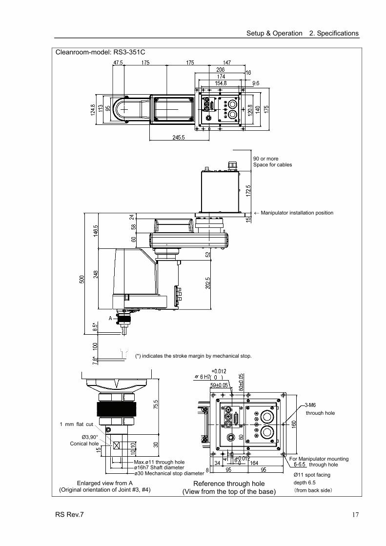
Setup & Operation 2. Specifications Cleanroom-model: RS3-351C
Ø3,90° Conical hole
1 mm flat cut
Max.ø11 through hole
Enlarged view from A (Original orientation of Joint #3, #4)
90 or more Space for cables
(*) indicates the stroke margin by mechanical stop.
Reference through hole (View from the top of the base)
ø16h7 Shaft diameter ø30 Mechanical stop diameter Ø11 spot facing
depth 6.5 (from back side)
through hole
through hole
For Manipulator mounting
← Manipulator installation position
RS Rev.7 17

Setup & Operation 2. Specifications
2.3.2 RS4-551* Standard-model: RS4-551S
Joint #2 (rotating)
Joint #1 (rotating)
Joint #4 (rotating)
Arm #1
Arm #2
Base+
−
+ −
+
−
+
− Shaft
Base
Arm #1
Arm #2
LED lamp
Signal Cable Power Cable
User Connector(15-pin D-sub Connector)
Fitting (white) for ø 6 mm pneumatic tube
Fitting (black or blue)* for ø 6 mm pneumatic tube
Fitting (white)for ø4 mm pneumatic tube
Signal Cable Power Cable
Joint #3 (up and down)
User Connector(15-pin D-sub Connector)
Joint #3 and #4 brake release switch
Fitting (white) for ø 6 mm pneumatic tube
Fitting (white) for ø4 mm pneumatic tube
Fitting (black or blue)*for ø 6 mm pneumatic tube
Signature label (Serial No. of Manipulator)
CE label
* Color differs depending on the shipment time
18 RS Rev.7
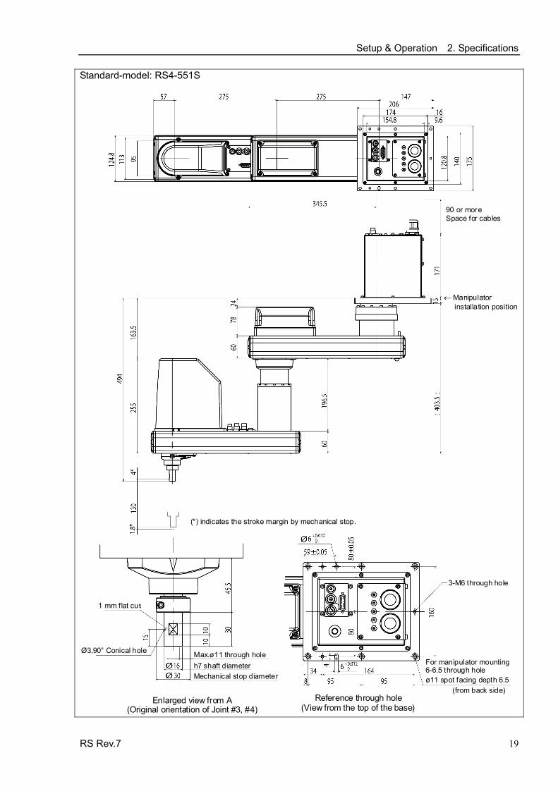
Setup & Operation 2. Specifications Standard-model: RS4-551S
Ø3,90° Conical hole
1 mm flat cut
Max.ø11 through hole
Enlarged view from A
(Original orientation of Joint #3, #4)
90 or more Space for cables
(*) indicates the stroke margin by mechanical stop.
Reference through hole (View from the top of the base)
h7 shaft diameterMechanical stop diameter ø11 spot facing depth 6.5
3-M6 through hole
For manipulator mounting6-6.5 through hole
(from back side)
← Manipulator installation position
RS Rev.7 19

Setup & Operation 2. Specifications
20 RS Rev.7
The following figures show the special parts for Cleanroom-model. These parts are different in appearance from Standard-model.
Cleanroom-model RS4-551C
Bellows Bellows
Exhaust port
Plate cover (For Anti-static)
Exhaust port

Setup & Operation 2. Specifications
RS Rev.7 21
Cleanroom-model RS4-551C
Ø3,90° Conical hole
1 mm flat cut
Max.ø11 through hole
Enlarged view from A (Original orientation of Joint #3, #4)
90 or more Space for cables
(*) indicates the stroke margin by mechanical stop.
Reference through hole(View from the top of the base)
h7 Shaft diameterMechanical stop diameter
Ø11 spot facing depth 6.5
3-M6 through hole
For Manipulator mounting6-6.5 through hole
← Manipulator installation position
(from back side)

Setup & Operation 2. Specifications
22 RS Rev.7
2.4 Specifications Item RS3-351* RS4-551*
Arm #1, #2 350 mm 550 mm Arm #1 175 mm 275 mm Arm length Arm #2 175 mm 275 mm Joints #1, #2 6237 mm/s 7400 mm/s Joints # 3 1100 mm/s Max.
operating speed *1 Joint #4 2600 deg/s Joints #1, #2 ± 0.01 mm ± 0.015 mm Joints # 3 ± 0.01 mm Repeatability Joint #4 ± 0.01 deg Rated 1 kg Payload (Load) Max. 3 kg 4 kg Rated 0.005 kg⋅m2 Joint #4 allowable
moment of inertia *2 Max. 0.05 kg⋅m2 Joint #1 ± 225 deg Joint #2 ± 225 deg
Joint #3 RS*-**1S: 130 mm RS*-**1C: 100 mm
Max. motion range
Joint #4 ± 720 deg Joint #1 − 2560000 to + 5973334 pulse −4096000 ~ + 9557334 pulse Joint #2 ± 4177920 pulse
Joint #3 RS*-**1S: − 1479112 pulse to 0 pulse RS*-**1C: − 1137778 pulse to 0 pulse
Max. pulse range (pulse)
Joint #4 ± 3145728 pulse Joint #1 0.0000527 deg/pulse Joint #2 0.0000538 deg/pulse Joint #3 0.0000879 mm/pulse
Resolution
Joint #4 0.000229 deg/pulse Mounting ø 16 mm Hand diameter Hollow ø 11 mm
Mounting hole 6-M6 Weight (cables not included) (Common to Standard & Cleanroom-model) 17 kg: 38 lb 19 kg: 42 lb
Driving method AC servo motor Joint #1 400 W Joint #2 200 W Joint #3 150 W
Motor power consumption
Joint #4 100 W Option Environment Cleanroom *3 & ESD Joint #3 down force 150 N Installed wire for customer use 15 wires: D-sub / 15 pin connectors
2 pneumatic tubes (ø 6 mm): 0.59 Mpa (6 kgf/cm2 : 86 psi) Installed pneumatic tube for customer use 1 pneumatic tube (ø 4 mm): 0.59 Mpa (6 kgf/cm2 : 86 psi)
Ambient temperature 5 to 40°C (with minimum temperature variation) Environmental requirements Ambient relative
humidity 10 to 80% RH (no condensation)
Noise level *4 LAeq = 70 dB (A) Applicable Controller RC180, RC620

Setup & Operation 2. Specifications
RS Rev.7 23
Item RS3-351* RS4-551* SPEED 1 to (5) to100 ACCEL *5 1 to (10) to 120 SPEEDS 1 to (50) to 2000 ACCELS 1 to (200) to 25000 FINE 0 to (10000) to 65000
Assignable Value ( ) Default values
WEIGHT 0,175 to (1,175) to 3,175 0,275 to (1,275) to 4,275 UL1740 (Third Edition, Dated December 7, 2007) ANSI/RIA R15.06-1999 NFPA 79 (2007 Edition) CSA/CAN Z434-03 (February 2003)
Safety standard
CE Marking − Machinery Directive, Low Voltage Directive, EMC Directive
*1: In the case of PTP command. Maximum operating speed for CP command is 2000 mm/s on horizontal plane.
*2: In the case where the center of gravity is at the center of Joint #4. If the center of gravity is not at the center of Joint #4, set the parameter using Inertia command.
*3: The exhaust system in the Cleanroom-model Manipulator draws air from the base interior and arm cover interior together. A crack or other opening in the base unit can cause loss of negative air pressure in the outer part of the arm, which can cause increased dust emission. Do not remove the maintenance cover on the front of the base. Seal the exhaust port and the exhaust tube with vinyl tape so that the joint is airtight. If the exhaust flow is not sufficient, dust particle emission may exceed the specified maximum level. Cleanliness level: Class ISO 3 (ISO14644-1)
Amount of Dust (0.1 µm diameter or larger) in 28317 cm3 (1cft) sample-air around the center of the motion rang: 10 particles or less.)
Exhaust System: Exhaust port diameter: Inner diameter: ø12 mm / Outer diameter: ø16 mm Exhaust tube : Polyurethane tube Outer diameter: ø12 mm (Inner diameter: ø8 mm) or Inner diameter ø16mm or larger Recommended exhaust flow rate: approx. 1000 cm3/s (Normal)
*4: Conditions of Manipulator during measurement as follows: Operating conditions : Under rated load, 4-joints simultaneous motion, maximum speed, maximum
acceleration, and duty 50%. Measurement point : In front of the Manipulator, 1000 mm apart from the motion range, 50 mm above
the base-installed surface.
*5: In general use, Accel setting 100 is the optimum setting that maintains the balance of acceleration and vibration when positioning. However, you may require an operation with high acceleration to shorten the cycle time by decreasing the vibration at positioning. In this case, set Accel to larger than 100. If you specify a larger Accel value, the frequency of the overload error and over heat may rise during continuous operation. The use of large Accel setting is recommended only for necessary motions.

Setup & Operation 2. Specifications
24 RS Rev.7
2.5 How to Set the Model
The Manipulator model for your system has been set before shipment from the factory. It is normally not required to change the model when you receive your system.
CAUTION
■ When you need to change the setting of the Manipulator model, be sure to set the Manipulator model properly. Improper setting of the Manipulator model may result in abnormal or no operation of the Manipulator and/or cause safety problems.
NOTE If an MT label is attached to the rear of a Manipulator, the Manipulator has custom
specifications. The custom specifications may require a different configuration procedure; check the custom specifications number described on the MT label and contact us when necessary. The Manipulator model can be set from software. Refer to the chapter Robot Configuration in the EPSON RC+ User’s Guide.

Setup & Operation 3. Environments and Installation
RS Rev.7 25
3. Environments and Installation
3.1 Environmental Conditions
A suitable environment is necessary for the robot system to function properly and safely. Be sure to install the robot system in an environment that meets the following conditions:
Item Conditions
Ambient temperature *1 5 to 40°C (with minimum temperature variation) Ambient relative humidity 10 to 80% (no condensation) First transient burst noise 2 kV or less Electrostatic noise 6 kV or less
Environment
· Install indoors · Keep away from direct sunlight · Keep away from dust, oily smoke, salinity,
metal powder or other contaminants · Keep away from flammable or corrosive solvents
and gases · Keep away from water · Keep away from shocks or vibrations · Keep away from sources of electric noise
NOTE Manipulators are not suitable for operation in harsh environments such as painting areas, etc. When using Manipulators in inadequate environments that do not meet the above conditions, please contact us.
*1 The ambient temperature conditions are for the Manipulators only. For the Controller the Manipulators are connected to, refer to the Controller manual.
3.2 Base Table A base table for anchoring the Manipulator is not supplied. Please make or obtain the base table for your Manipulator. The shape and size of the base table differs depending on the use of the robot system. For your reference, we list some Manipulator table requirements here.
The base table must not only be able to bear the weight of the Manipulator but also be able to withstand the dynamic movement of the Manipulator when the Manipulator operates at maximum acceleration. Ensure that there is enough strength on the base table by attaching reinforcing materials such as crossbeams. The torque and reaction force produced by the movement of the Manipulator are as follows:
Max. Reaction torque on the horizontal plate : 500 Nm Max. Horizontal reaction force : 1200 N (RS3-351*) : 1400 N (RS4-551*) Max. Vertical reaction force : 1100 N
The threaded holes required for mounting the Manipulator base are M6. Use mounting bolts with specifications conforming to ISO898-1 property class: 10.9 or 12.9. For dimensions, refer to Setup & Operation: 3.3 Mounting Dimensions.

Setup & Operation 3. Environments and Installation
26 RS Rev.7
The plate for the Manipulator mounting face should be 20 mm thick or more and made of steel to reduce vibration. The surface roughness of the steel plate should be 25 μm or less.
The table must be secured on the floor or wall to prevent it from moving.
The Manipulator must be installed horizontally.
When using a leveler to adjust the height of the base table, use a screw with M16 diameter or more.
If you are passing cables through the holes on the base table, see the figures below.
RS series Manipulator (Figure: RS3-351S)
RC180 Controller M/C Power Cable
M/C Signal Cable
Power Cable Connector
Signal Cable Connector
47
26
53 18
[unit : mm]
Do not remove the M/C cables from the Manipulator.
The M/C cables are installed to the Manipulator body and can not be removed. Never try to remove the M/C cables.
In case that the base table has no maintenance window*, it needs to remove the Manipulator from the base table for the maintenance. When designing the base table, consider this point. (* Refer to next page.)
NOTE For environmental conditions regarding space when placing the Controller on the base table, refer to the Controller manual.
WARNING
■ To ensure safety, a safeguard must be installed for the robot system. For details on the safeguard, refer to the EPSON RC+ User’s Guide.

Setup & Operation 3. Environments and Installation
RS Rev.7 27
Base Table – Design Example The following is an example for designing the base table of RS3 Manipulator. During the operation of RS3 in the maximum acceleration/deceleration speed, the base table must be steady enough to prevent the vibration from transmitting to RS3.
Adjustable bolt
Joint #1 Center of rotation
Space for Controller
Operating height
Maintenance window X
Y
AA
: Make space for the Arm #1 coverto remove
Wight of table : approx. 250 kg Material for the flame : Iron pipe: □ 100 × 50 mm 3.2 mm thick Adjustable bolt : M36 Geometrical moment of inertia : Ix = 10.3 × 108 mm4
(A-A) Iy = 10.3 × 108 mm4 - Set low aspect ratio of the base table height and width - Put center of gravity lower position by installing the Controller on the bottom of
the base table. - Reinforce the open part with joist or similar material to minimize the part. - The condition depends on the table height, width, the position of joist, and the
center of gravity.
Setup & Operation 3. Environments and Installation
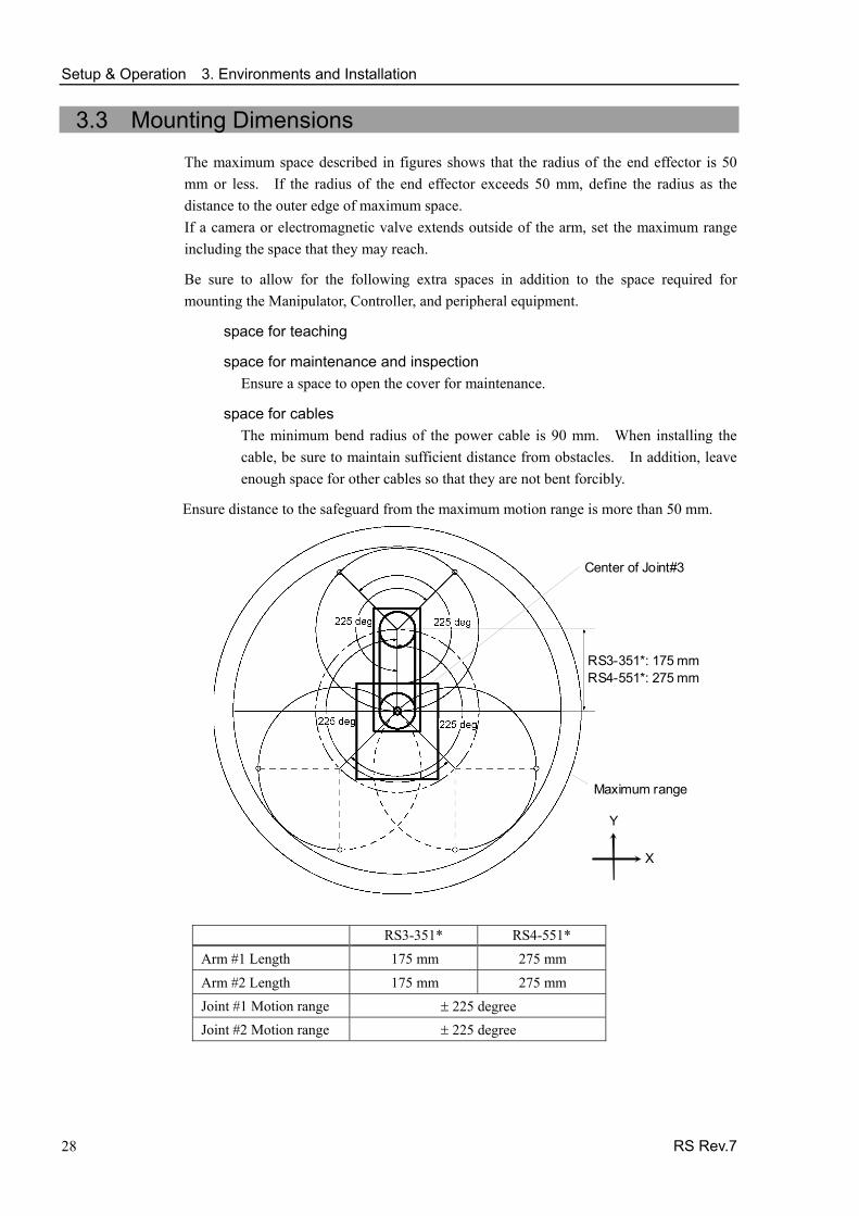
3.3 Mounting Dimensions
The maximum space described in figures shows that the radius of the end effector is 50 mm or less. If the radius of the end effector exceeds 50 mm, define the radius as the distance to the outer edge of maximum space. If a camera or electromagnetic valve extends outside of the arm, set the maximum range including the space that they may reach.
Be sure to allow for the following extra spaces in addition to the space required for mounting the Manipulator, Controller, and peripheral equipment.
space for teaching
space for maintenance and inspection Ensure a space to open the cover for maintenance.
space for cables The minimum bend radius of the power cable is 90 mm. When installing the cable, be sure to maintain sufficient distance from obstacles. In addition, leave enough space for other cables so that they are not bent forcibly.
Ensure distance to the safeguard from the maximum motion range is more than 50 mm.
Center of Joint#3
Maximum range
Y
X
RS3-351*: 175 mm RS4-551*: 275 mm
RS3-351* RS4-551* Arm #1 Length 175 mm 275 mm
Arm #2 Length 175 mm 275 mm Joint #1 Motion range ± 225 degree Joint #2 Motion range ± 225 degree
28 RS Rev.7

Setup & Operation 3. Environments and Installation
3.4 Unpacking and Transportation
THE INSTALLATION SHALL BE PREFORMED BY QUALIFIED INSTALLATION PERSONNEL AND SHOULD CONFORM TO ALL NATIONAL AND LOCAL CODES.
WARNING
■ Only authorized personnel should perform sling work and operate a crane and a forklift. When these operations are performed by unauthorized personnel, it is extremely hazardous and may result in serious bodily injury and/or severe equipment damage to the robot system.
■ Using a cart or similar equipment, transport the Manipulator in the same manner
as it was delivered.
■ After removing the bolts securing the Manipulator to the delivery equipment, the Manipulator can fall. Be careful not to get hands or fingers caught.
■ The arm is secured with a wire tie. Leave the wire tie secured until you finish the installation so as not to get hands or fingers caught.
■ To carry the Manipulator, have two or more people to work on it and secure the Manipulator to the delivery equipment or hold the areas indicated in gray in the figure (bottom of Arm #1 and bottom of the base) by hand. When holding the bottom of the base by hand, be very careful not to get your hands or fingers caught.
RS3-351* : approx. 17 kg : 38 lb.
RS4-551* : approx. 19 kg : 42 lb.
■ Stabilize the Manipulator with your hands when hoisting it.
CAUTION
■ When transporting the Manipulator for a long distance, secure it to the delivery equipment directly so that the Manipulator never falls. If necessary, pack the Manipulator in the same style as it was delivered.
RS Rev.7 29

Setup & Operation 3. Environments and Installation
30 RS Rev.7
3.5 Installation
CAUTION
■ The robot system must be installed to avoid interference with buildings, structures, utilities, other machines and equipment that may create a trapping hazard or pinch points.
3.5.1 Standard-model
■ Install the Manipulator with two or more people.
The Manipulator weights are as follows. Be careful not to get hands, fingers, or feet caught and/or have equipment damaged by a fall of the Manipulator. RS3-351*: approx. 17 kg : 38 Ib. (except cables)
RS4-551* : approx. 19 kg : 42 lb. (except cables) CAUTION ■ When installing the Manipulator to the ceiling, support the Manipulator, and then
secure the anchor bolts. Removing the support without securing the anchor bolts properly is extremely hazardous and may result in fall of the Manipulator.
(1) Unpack the Manipulator with retaining the
arm posture.
(2) Secure the base to the wall with 6 bolts.
Intensity of the bolts should be equivalent to ISO898-1 Property Class 10.9 or 12.9.
6-M6×20
Screw hole (Depth: 12 mm
or more)
NOTE

Setup & Operation 3. Environments and Installation
RS Rev.7 31
3.5.2 Cleanroom-model (1) Unpack it outside of the clean room.
(2) Secure the Manipulator to delivery equipment such as a pallet with bolts so that the Manipulator does not fall.
(3) Wipe off the dust on the Manipulator with a little alcohol or distilled water on a lint-free cloth.
(4) Carry the Manipulator in the clean room.
(5) Refer to the installation procedure of each Manipulator model and install the Manipulator.
(6) Connect an exhaust tube to the exhaust port.

Setup & Operation 3. Environments and Installation
3.6 Connecting the Cables
■ To shut off power to the robot system, pull out the power plug from the power source. Be sure to connect the AC power cable to a power receptacle. DO NOT connect it directly to a factory power source.
■ Before performing any replacement procedure, turn OFF the Controller and related equipment, and then pull out the power plug from the power source. Performing any replacement procedure with the power ON is extremely hazardous and may result in electric shock and/or malfunction of the robot system.
■ Be sure to connect the cables properly. Do not allow unnecessary strain on the cables. (Do not put heavy objects on the cables. Do not bend or pull the cables forcibly.) The unnecessary strain on the cables may result in damage to the cables, disconnection, and/or contact failure. Damaged cables, disconnection, or contact failure is extremely hazardous and may result in electric shock and/or improper function of the robot system.
WARNING
■ Grounding the manipulator is done by connecting with the controller. Ensure that the controller is grounded and the cables are correctly connected. If the ground wire is improperly connected to ground, it may result in the fire or electric shock.
CAUTION
■ When connecting the Manipulator to the Controller, make sure that the serial numbers on each equipment match. Improper connection between the Manipulator and Controller may not only cause improper function of the robot system but also serious safety problems. The connection method varies with the Controller used. For details on the connection, refer to the Controller manual. If the Manipulator G series, E2 series or RS series is connected to the Controller for the 6-axis, it may result in malfunction of the Manipulator.
When the Manipulator is a Cleanroom-model, use it with an exhaust system. For details, refer to Setup & Operation: 2.4 Specifications.
Cable Connections Connect the power connector and signal connector of the M/C cables to the Controller.
Manipulator RS series (Figure: RS3-351S)
Controller RC180 M/C Power cable
M/C Signal cable
32 RS Rev.7

Setup & Operation 3. Environments and Installation
RS Rev.7 33
3.7 User Wires and Pneumatic Tubes
CAUTION
■ Only authorized or certified personnel should be allowed to perform wiring. Wiring by unauthorized or uncertified personnel may result in bodily injury and/or malfunction of the robot system.
User electrical wires and pneumatic tubes are contained in the cable unit. Electrical Wires
Rated Voltage Allowable Current Wires Nominal Sectional Area Outer Diameter Note
AC/DC30 V 1 A 15 0.211 mm2 ø8.3±0.3 mm Shielded
Maker Standard
Suitable Connector JAE DA-15PF-N (Solder type) 15 pin Clamp Hood JAE DA-C8-J10-F2-1R (Connector setscrew: #4-40 NC)
Pins with the same number, indicated on the connectors on both ends of the cables, are connected.
Pneumatic Tubes
Max. Usable Pneumatic Pressure Pneumatic Tubes Outer Diameter × Inner Diameter
2 ø6 mm × ø4 mm 0.59 MPa (6 kgf/cm2 : 86 psi)1 ø4 mm × ø2.5 mm
Fittings for ø6 mm and ø4 mm (outer diameter) pneumatic tubes are supplied on both ends of the pneumatic tubes.
A
BA
B
A
B
RS3-351*
RS4-551*
Fitting (white)for ø4 mm pneumatic tube
Fitting (black or blue)* for ø6 mm pneumatic tube
User connector (15-pin D-sub connector)
Joint #3 break release switch
Fitting (white) for ø6 mm pneumatic tube
Fitting (white) for ø4 mm pneumatic tube
Fitting (black or blue)*for ø6 mm pneumatic tube
User connector (15-pin D-sub connector)
Fitting (white)for ø4 mm pneumatic tube
* Color differs depending on the shipment time
NOTE The Joint #4 (rotating) motion range is ±720 degrees. Be careful not to let the wires/tubes caught in the end effector.

Setup & Operation 3. Environments and Installation
3.8 Relocation and Storage
3.8.1 Precautions for Relocation and Storage Observe the following when relocating, storing, and transporting the Manipulators.
THE INSTALLATION SHALL BE PREFORMED BY QUALIFIED INSTALLATION PERSONNEL AND SHOULD CONFORM TO ALL NATIONAL AND LOCAL CODES.
WARNING
■ Only authorized personnel should perform sling work and operate a crane and a forklift. When these operations are performed by unauthorized personnel, it is extremely hazardous and may result in serious bodily injury and/or severe equipment damage to the robot system.
■ Before relocating the Manipulator, fold the arm and secure it tightly with a wire tie to prevent hands or fingers from being caught in the Manipulator.
■ When removing the anchor bolts, support the Manipulator to prevent falling. Removing the anchor bolts without support may result in a fall of the Manipulator, and then get hands, fingers, or feet caught.
■ To carry the Manipulator, have two or more people to work on it and secure the Manipulator to the delivery equipment or hold the areas indicated in gray in the figure (bottom of Arm #1 and bottom of the base) by hand. When holding the bottom of the base by hand, be very careful not to get your hands or fingers caught.
RS3-351* : approx. 17 kg : 38 lb. RS4-551* : approx. 19 kg : 42 lb.
CAUTION
■ Stabilize the Manipulator with your hands when hoisting it. Unstable hoisting is extremely hazardous and may result in fall of the Manipulator.
When transporting the Manipulator for a long distance, secure it to the delivery equipment so that the Manipulator cannot fall. If necessary, pack the Manipulator in the same way as it was delivered.
When the Manipulator is used for a robot system again after long-term storage, perform a test run to verify that it works properly, and then operate it thoroughly.
Transport and store the Manipulator in the range of -25°C to +55°C.
Humidity within 10% to 90% is recommended.
When condensation occurs on the Manipulator during transport or storage, turn ON the power only after the condensation dries.
Do not shock or shake the Manipulator during transport.
34 RS Rev.7
Setup & Operation 3. Environments and Installation
3.8.2 Relocation procedure
■ Install or relocate the Manipulator with two or more people. The Manipulator weights are as follows. Be careful not to get hands, fingers, or feet caught and/or have equipment damaged by a fall of the Manipulator. RS3-351* : approx. 17 kg: 38 lb. RS4-551* : approx. 19 kg: 42 lb.
WARNING ■ When removing the Manipulator from the ceiling, support the Manipulator, and then remove the anchor bolts. Removing the anchor bolts without supporting is extremely hazardous and may result in fall of the Manipulator. (1) Turn OFF the power on all devices and unplug the cables.
(2) Hold the bottom of Arm #1 by hand to unscrew the anchor bolts. Then, remove the Manipulator.
RS Rev.7 35

Setup & Operation 4. Setting of End Effectors
36 RS Rev.7
4. Setting of End Effectors
4.1 Attaching an End Effector Users are responsible for making their own end effector(s). Before attaching an end effector, observe these guidelines.
CAUTION
■ If you use an end effector equipped with a gripper or chuck, connect wires and/or pneumatic tubes properly so that the gripper does not release the work piece when the power to the robot system is turned OFF. Improper connection of the wires and/or pneumatic tubes may damage the robot system and/or work piece as the work piece is released when the Emergency Stop switch is pressed. I/O outputs are configured at the factory so that they are automatically shut off (0) by power disconnection, the Emergency Stop switch, or the safety features of the robot system.
Shaft - Attach an end effector to the lower end of the shaft.
For the shaft dimensions, and the overall dimensions of the Manipulator, refer to Setup & Operation: 2. Specifications.
- Do not move the upper limit mechanical stop on the lower side of the shaft.Otherwise, when “Jump motion” is performed, the upper limit mechanical stop may hit the Manipulator, and the robot system may not function properly.
- Use a split muff coupling with an M4 bolt or larger to attach the end effector to theshaft.
Brake release switch - Joint #3 cannot be moved up/down by hand because the electromagnetic brake is
applied while power to the robot system is turned OFF.
This prevents the shaft from hitting peripheral equipment in the case that the shaft is lowered by the weight of the end effector when the power is disconnected during operation, or when the motor is turned OFF even though the power is turned ON. When attaching an end effector, turn ON the Controller. Move Joint #3 up/downwhile pressing the brake release switch.
This button switch is a momentary-type; the brake is released only while the button switch is being pressed.
- Be careful of the shaft falling and rotating while the brake release switch is beingpressed because the shaft may be lowered by the weight of the end effector.
RS4-551*RS3-351*
Brake release switch
The shaft may be lowered by the weight of the end effector.

Setup & Operation 4. Setting of End Effectors
RS Rev.7 37
4.2 Attaching Cameras and Air valves
Arm #2 has threaded holes as shown in the figure below. Use these holes for attaching cameras, air valves, and other equipment. [Unit : mm]
4-M4 depth 5
4-M4 depth 5
RS3-351* RS4-551*
- When cameras and air valves are attached, it can limit the motion range by wires and pneumatic tubes. Take extra care when designing and attaching.
NOTE
- The Joint #4 (rotating) motion range is ±720 degrees. Be careful not to let the wires/tubes caught in the end effector.
4.3 Weight and Inertia Settings To ensure optimum Manipulator performance, it is important to make sure that the load (weight of the end effector and work piece) and moment of inertia of the load are within the maximum rating for the Manipulator, and that Joint #4 does not become eccentric. If the load or moment of inertia exceeds the rating or if the load becomes eccentric, follow the steps below, “4.3.1Weight Setting” and “4.3.2 Inertia Setting” to set parameters. Setting parameters makes the PTP motion of the Manipulator optimal, reduces vibration to shorten the operating time, and improves the capacity for larger loads. In addition, it reduces persistent vibration produced when the moment of inertia of the end effector and work piece is larger that the default setting.
4.3.1 Weight Setting
CAUTION
■ The total weight of the end effector and the work piece must not exceed RS3-351*: 3 kg / RS4-551*: 4 kg. The RS series Manipulators are not designed to work with loads exceeding RS3-351*: 3 kg / RS4-551*: 4 kg. Always set the Weight parameters according to the load. Setting a value that is smaller than the actual load may cause errors, excessive shock, insufficient function of the Manipulator, and/or shorten the life cycle of parts/mechanisms.
The acceptable weight capacity (end effector and work piece) in RS series is 1 kg at the default rating and RS3-351*: 3 kg / RS4-551*: 4 kg at the maximum. When the load (weight of the end effector and work piece) exceeds the rating, change the setting of Weight parameter. After the setting is changed, the maximum acceleration/deceleration speed of the robot system at PTP motion corresponding to the “Weight Parameter” is set automatically.

Setup & Operation 4. Setting of End Effectors
Load on the Shaft The load (weight of the end effector and work piece) on the shaft can be set by Weight parameter.
EPSON RC+
Enter a value into the [Load inertia:] text box on the [Inertia] panel ([Tools] - [Robot Manager]). (You may also execute the Inertia command from the [Command Window].)
Load on the Arm
When you attach a camera or other devices to the arm, calculate the weight as the equivalent of the shaft. Then, add this to the load and enter the total weight to the Weight parameter. Equivalent Weight Formula
When you attach the equipment near Arm #2: When you attach the equipment to the end of Arm #2:
WM = M (L1)2/(L1+L2)2 WM = M (LM)2/(L2)2
WM M L1 L2 LM
: equivalent weight : weight of camera etc. : length of Arm #1 : length of Arm #2 : distance from rotation center of Joint #2 to center of gravity of camera etc.
<Example> A “0.5 kg” camera is attached to the end of the RS series arm (450 mm
away from the rotation center of Joint #2) with a load weight of “1 kg”. M = 0.5
L2 = 175 LM = 250 WM = 0.5 × 2502/1752 = 1.02 → 1.1 (round up) W + WM = 1 + 1.1 = 2.1 Enter “2.1” for the Weight Parameter.
Automatic speed setting by Weight
38 RS Rev.7
140
120
100
80
60
4020
0 0.5 1 1.5 2 2.5 3 3.5 4 (kg) Weight setting
(%)
100 100 100 100
* The percentage in the graph is based on the speed at rated weight (1 kg) as 100%.
100
RS3-351* RS4-551*
Setup & Operation 4. Setting of End Effectors
RS Rev.7 39
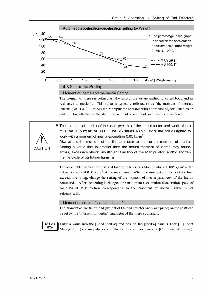
Automatic acceleration/deceleration setting by Weight (%)140
120
100
80
60
40
20
0 0.5 1 1.5 2 2.5 3 3.5 4 (kg) Weight setting
100
120
70
40 30
120
50RS3-351*RS4-551*
* The percentage in the graph is based on the acceleration/ deceleration at rated weight(1 kg) as 100%.
4.3.2 Inertia Setting Moment of Inertia and the Inertia Setting
The moment of inertia is defined as “the ratio of the torque applied to a rigid body and its resistance to motion”. This value is typically referred to as “the moment of inertia”, “inertia”, or “GD2”. When the Manipulator operates with additional objects (such as an end effector) attached to the shaft, the moment of inertia of load must be considered.
CAUTION
■ The moment of inertia of the load (weight of the end effector and work piece) must be 0.05 kg m2 or less. The RS series Manipulators are not designed to work with a moment of inertia exceeding 0.05 kg m2. Always set the moment of inertia parameter to the correct moment of inertia. Setting a value that is smaller than the actual moment of inertia may cause errors, excessive shock, insufficient function of the Manipulator, and/or shorten the life cycle of parts/mechanisms.
The acceptable moment of inertia of load for a RS series Manipulator is 0.005 kg m2 at the default rating and 0.05 kg m2 at the maximum. When the moment of inertia of the load exceeds the rating, change the setting of the moment of inertia parameter of the Inertia command. After the setting is changed, the maximum acceleration/deceleration speed of Joint #4 at PTP motion corresponding to the “moment of inertia” value is set automatically.
Moment of inertia of load on the shaft The moment of inertia of load (weight of the end effector and work piece) on the shaft can be set by the “moment of inertia” parameter of the Inertia command.
EPSON RC+
Enter a value into the [Load inertia:] text box on the [Inertia] panel ([Tools] - [Robot Manager]). (You may also execute the Inertia command from the [Command Window].)

Setup & Operation 4. Setting of End Effectors
40 RS Rev.7
Automatic acceleration/deceleration setting of Joint #4 by Inertia (moment of inertia)
140
120
100
80
60
40
20
(%)
100
120
70
40
0 0.50 1.00 1.50 2.00 2.50 3.00 3.50 (kg・m2) Moment of inertia setting
Eccentric Quantity and the Inertia Setting
CAUTION
■ The eccentric quantity of load (weight of the end effector and work piece) must be 100 mm or less. The RS series Manipulators are not designed to work with eccentric quantity exceeding 100 mm. Always set the eccentric quantity parameter according to the eccentric quantity. Setting a value that is smaller than the actual eccentric quantity may cause errors, excessive shock, insufficient function of the Manipulator, and/or shorten the life cycle of parts/mechanisms. The acceptable eccentric quantity of load in RS series is 0 mm at the default rating and 100 mm at the maximum. When the eccentric quantity of load exceeds the rating, change the setting of eccentric quantity parameter of Inertia command. After the setting is changed, the maximum acceleration/deceleration speed of the Manipulator at PTP motion corresponding to the “eccentric quantity” is set automatically.
Position of load’s center of gravity
Rotation center
Eccentric quantity (100 mm or less)
Eccentric Quantity

Setup & Operation 4. Setting of End Effectors
Eccentric quantity of load on the shaft The eccentric quantity of load (weight of the end effector and work piece) on the shaft can be set by “eccentric quantity” parameter of Inertia command.
EPSON RC+
Enter a value into the [Eccentricity:] text box on the [Inertia] panel ([Tools] - [Robot Manager]). (You may also execute the Inertia command from the [Command Window].)
Automatic acceleration/deceleration setting by Inertia (eccentric quantity)
120
100
80
60
40
20
(%)100
70
30
RS Rev.7 41
0 25 50 75 100 (mm) Eccentricity setting
20
RS3-351* RS4-551*
80
40
* The percentage in the graph is based on the acceleration/deceleration at rated eccentricity (0 mm) as 100%.
20
Calculating the Moment of Inertia
Refer to the following examples of formulas to calculate the moment of inertia of load (end effector with work piece). The moment of inertia of the entire load is calculated by the sum of each part (a), (b), and (c).
Work piece (b) Work piece (c)
End effector (a)
Joint #3 shaft
Rotation center
Moment of inertia of end effector (a)
= Moment of inertia of work piece (b)
+ Moment of inertia of work piece (c)
+ Whole moment of inertia

Setup & Operation 4. Setting of End Effectors
42 RS Rev.7
The methods for calculating the moment of inertia for (a), (b), and (c) are shown below. Calculate the total moment of inertia using the basic formulas.
(a) Moment of inertia of a rectangular parallelepiped
h b
L
Mass (m)
Rectangular parallelepiped’s center of gravity Rotation center
m + m × L2 b2 + h2 12
(b) Moment of inertia of a cylinder
m + m × L2 r 2
2Mass (m)
L
r
Cylinder’s center of gravity Rotation center
(c) Moment of inertia of a sphere
m r 2+ m × L2 25
Sphere’s center of gravity
r
Mass (m)
L
Rotation center

Setup & Operation 4. Setting of End Effectors
RS Rev.7 43
4.4 Precautions for Auto Acceleration/Deceleration of Joint #3
When you move the Manipulator in horizontal PTP motion with Joint #3 (Z) at a high position, the motion time will be faster. When Joint #3 gets below a certain point, then auto acceleration/deceleration is used to reduce acceleration/deceleration. (Refer to the figure below.) The higher the position of the shaft is, the faster the motion acceleration/deceleration is. However, it takes more time to move Joint #3 up and down. Adjust the position of Joint #3 for the Manipulator motion after considering the relation between the current position and the destination position. The upper limit of Joint #3 during horizontal motion using Jump command can be set by the LimZ command.
Automatic acceleration/deceleration vs. Joint #3 position 120
100
80
60
40
20
0 -20 -60 -100 -140 (mm) Height of the shaft
(%)100
50
100
RS3-351* RS4-551*
100* The percentage in the graph is
based on the acceleration / deceleration at the upper-limited position of Joint #3
NOTE When moving the Manipulator horizontally while the shaft is being lowered, it may cause over-shoot at the time of final positioning.

Setup & Operation 5. Motion Range
44 RS Rev.7
5. Motion Range
CAUTION
■ When setting up the motion range for safety, both the pulse range and mechanical stops must always be set at the same time.
The motion range is preset at the factory as explained in Setup & Operation: 5.4 Standard Motion Range. That is the maximum motion range of the Manipulator.
There are three methods for setting the motion range described as follows:
1. Setting by pulse range (for all joints)
2. Setting by mechanical stops (for Joints #3)
3. Setting the Cartesian (rectangular) range in the X, Y coordinate system of the Manipulator (for Joints #1 and #2)
Mechanical stop
Rectangular range setting
Pulse range
Motion range Mechanical stop
When the motion range is changed due to layout efficiency or safety, follow the descriptions in 5.1 to 5.3 to set the range.
5.1 Motion Range Setting by Pulse Range
Pulses are the basic unit of Manipulator motion. The motion range of the Manipulator is controlled by the pulse range between the pulse lower limit and upper limit of each joint. Pulse values are read from the encoder output of the servo motor.
For the maximum pulse range, refer to the following sections. The pulse range must be set inside of the mechanical stop range.
5.1.1 Max. Pulse Range of Joint #1 5.1.2 Max. Pulse Range of Joint #2 5.1.3 Max. Pulse Range of Joint #3 5.1.4 Max. Pulse Range of Joint #4.
NOTE Once the Manipulator receives an operating command, it checks whether the target position specified by the command is within the pulse range before operating. If the target position is out of the set pulse range, an error occurs and the Manipulator does not move.
EPSON RC+
The pulse range can be set on the [Range] panel shown by selecting [Tools]-[Robot Manager]. (You may also execute the Range command from the [Command Window].)
Setup & Operation 5. Motion Range
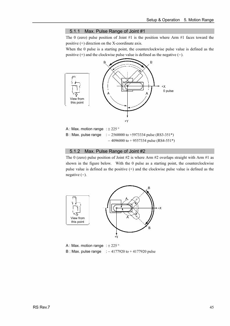
5.1.1 Max. Pulse Range of Joint #1 The 0 (zero) pulse position of Joint #1 is the position where Arm #1 faces toward the positive (+) direction on the X-coordinate axis. When the 0 pulse is a starting point, the counterclockwise pulse value is defined as the positive (+) and the clockwise pulse value is defined as the negative (-).
0 pulse
View from this point
A : Max. motion range : ± 225 ° B : Max. pulse range : − 2560000 to +5973334 pulse (RS3-351*) − 4096000 to + 9557334 pulse (RS4-551*)
5.1.2 Max. Pulse Range of Joint #2
The 0 (zero) pulse position of Joint #2 is where Arm #2 overlaps straight with Arm #1 as shown in the figure below. With the 0 pulse as a starting point, the counterclockwise pulse value is defined as the positive (+) and the clockwise pulse value is defined as the negative (-).
View from this point
A : Max. motion range : ± 225 ° B : Max. pulse range : − 4177920 to + 4177920 pulse
RS Rev.7 45

Setup & Operation 5. Motion Range
46 RS Rev.7
5.1.3 Max. Pulse Range of Joint #3
The 0 (zero) pulse position of Joint #3 is the position where the shaft is at its upper limit. The pulse value is always negative because Joint #3 always moves lower than the 0 pulse position.
Upper limit: 0 pulse
Type Joint #3 stroke Lower limit pulse value RS3-351S/RS4-551S 130 mm − 1479112 pulse RS3-351C/RS4-551C 100 mm − 1137778 pulse
5.1.4 Max. Pulse Range of Joint #4
The 0 (zero) pulse position of Joint #4 is the position where the flat near the end of the shaft faces toward the end of Arm #2. With the 0 pulse as a starting point, the counterclockwise pulse value is defined as the positive (+) and the clockwise pulse value is defined as the negative (-).
0 pulse ± 3145728 pulse
View from this point
NOTE
The Joint #4 (rotating) motion range is ±720 degrees.

Setup & Operation 5. Motion Range
RS Rev.7 47
5.2 Motion Range Setting by Joint #3 Mechanical Stops
(1) Turn ON the Controller and turn OFF the motors using the Motor OFF command.
(2) Remove the Arm #2 cover (4-M4×10).
(3) Push up the shaft while pressing the brake release switch.
When you press the brake release switch, the shaft may lower due to the weight of the end effector. Be sure to hold the shaft by hand while pressing the button.
Lower limit mechanical stop M3×10
Brake releaseswitch
Shaft
Illustration: RS3-351S
(4) Turn OFF the Controller.
(5) Loosen the lower limit mechanical stop screw (M3×10).
A mechanical stop is mounted on both the top and bottom of Joint #3. However, onlythe position of the lower limit mechanical stop on the top can be changed. Do notremove the upper limit mechanical stop on the bottom because the calibration point ofJoint #3 is specified using the stop.
Measure this distance.
(6) The upper end of the shaft defines the maximum stroke. Move the lower limit mechanical stop down by the length you want to limit the stroke. For example, when the lower limit mechanical stop is set at “130 mm” stroke, the lower limit Z coordinate value is “−130”. To change the value to “−100”, move the lower limit mechanical stop down “30 mm”. Use calipers to measure the distance when adjusting the mechanical stop.
(7) Firmly tighten two lower limit mechanical stop screws (M3×10). Recommended tightening torque: 245 N⋅cm (25 kgf⋅cm)
(8) Turn ON the Controller.
(9) Move Joint #3 to its lower limit while pressing the brake release switch, and then check the lower limit position. Do not lower the mechanical stop too far. Otherwise, the joint may not reach a target position.
NOTE
NOTE

Setup & Operation 5. Motion Range
48 RS Rev.7
(10) Calculate the lower limit pulse value of the pulse range using the formula shown below
and set the value.
The result of the calculation is always negative because the lower limit Z coordinatevalue is negative.
Lower limit of pulse (pulse)
= lower limit Z coordinate value (mm) / Resolution (mm/pulse)
** For the Joint #3 resolution, refer to the section Setup & Operation 2.4 Specifications.
EPSON RC+
Execute the following command from the [Command Window]. Enter thecalculated value in X. >JRANGE 3,X,0 ' Sets the pulse range of Joint #3
(11) Use the Pulse command (Go Pulse command), and move Joint #3 to the lower limit position of the pulse range at low speed.
If the mechanical stop range is less than the pulse range, Joint #3 will hit the mechanical stop and an error will occur. When the error occurs, either change the pulse range to a lower setting or extend the position of the mechanical stop within the limit.
If it is difficult to check whether Joint #3 hits a mechanical stop, turn OFF the Controller and lift the arm top cover to check the condition causing theproblem from the side.
EPSON RC+
Execute the following commands from the [Command Window]. Enter the value calculated in Step (10) in X. >MOTOR ON ' Turns ON the motor >SPEED 5 ' Sets low speed >PULSE 0,0,X,0 ' Moves to the lower limit-pulse position of Joint #3.
(In this example, all pulses except those for Joint #3 are “0”. Substitute these “0s” with the other pulse valuesspecifying a position where there is no interference even when lowering Joint #3.)
NOTE

Setup & Operation 5. Motion Range
5.3 Setting the Cartesian (Rectangular) Range in the XY Coordinate System of the Manipulator (for Joints #1 and #2)
Use this method to set the upper and lower limits of the X and Y coordinates.
This setting is only enforced by software. Therefore, it does not change the physical range. The maximum physical range is based on the position of the mechanical stops.
EPSON RC+
Set the XYLim setting on the [XYZ Limits] panel shown by selecting [Tools]-[Robot Manager]. (You may also execute the XYLim command from the [Command Window].)
RS Rev.7 49

Setup & Operation 5. Motion Range
5.4 Standard Motion Range The following “motion range” diagrams show the standard (maximum) specification. When each Joint motor is under servo control, the center of Joint #3’s (shaft’s) lowest point moves in the areas shown in the figure.
“Area limited by mechanical stop” is the area where the center of Joint #3’s lowest point can be moved when each joint motor is not under servo control.
“Mechanical stop” sets the limited motion range so that the center of Joint #3 cannot move beyond the area mechanically.
A
B C
D
E
F
Max rangeMotion range
Center of Joint #3
RS3-351S RS3-351C RS4-551S RS4-551C A R350 R550 B R175 R275 C 175 mm 275 mm Arm#1, Arm#2 length
D 4 6.5 6 8.5 Joint #3 range to hit upper mechanical stop
E 130 100 130 100 Joint #3 stroke
F 1.8 3.8 4.8 7.8 Joint #3 range to hit lower mechanical stop
50 RS Rev.7

Maintenance This volume contains maintenance procedures with safety
precautions for RS series Manipulators.

52

Maintenance 1. Safety Maintenance
1. Safety Maintenance Please read this chapter, this manual, and other relevant manuals carefully to understand safe maintenance procedures before performing any routine maintenance. Only authorized personnel who have taken safety training should be allowed to maintain the robot system. Safety training is the program for industrial robot operators that follows the laws and regulations of each nation. The personnel who have taken safety training acquire knowledge of industrial robots (operations, teaching, etc.), knowledge of inspections, and knowledge of related rules/regulations. The personnel who have completed the robot system-training and maintenance- training classes held by the manufacturer, dealer, or locally-incorporated company are allowed to maintain the robot system.
When removing the arm from the Manipulator, for such as replacing the reduction gear unit, it must be done by two or more personnel. For removing the Arm #1 cover, in case that the maintenance window is not installed to the base table, it needs to remove the Manipulator from the base table. Removing the Manipulator must be done by two or more personnel.
■ Do not remove any parts that are not covered in this manual. Follow the maintenance procedure strictly as described in this manual. Improper removal of parts or improper maintenance may not only cause improper function of the robot system but also serious safety problems.
■ Keep away from the Manipulator while the power is ON if you have not taken the training courses. Do not enter the operating area while the power is ON. Entering the operating area with the power ON is extremely hazardous and may cause serious safety problems as the Manipulator may move even it seems to be stopped.
■ When you check the operation of the Manipulator after replacing parts, be sure to check it while you are outside of the safeguarded area. Checking the operation of the Manipulator while you are inside of the safeguarded area may cause serious safety problems as the Manipulator may move unexpectedly.
WARNING
■ Before operating the robot system, make sure that both the Emergency Stop switches and safeguard switch function properly. Operating the robot system when the switches do not function properly is extremely hazardous and may result in serious bodily injury and/or serious damage to the robot system as the switches cannot fulfill their intended functions in an emergency.
RS Rev.7 53
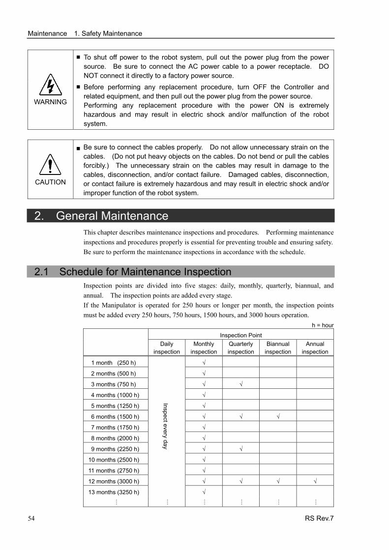
Maintenance 1. Safety Maintenance
■ To shut off power to the robot system, pull out the power plug from the power source. Be sure to connect the AC power cable to a power receptacle. DO NOT connect it directly to a factory power source.
WARNING
■ Before performing any replacement procedure, turn OFF the Controller and related equipment, and then pull out the power plug from the power source. Performing any replacement procedure with the power ON is extremely hazardous and may result in electric shock and/or malfunction of the robot system.
CAUTION
■ Be sure to connect the cables properly. Do not allow unnecessary strain on the cables. (Do not put heavy objects on the cables. Do not bend or pull the cables forcibly.) The unnecessary strain on the cables may result in damage to the cables, disconnection, and/or contact failure. Damaged cables, disconnection, or contact failure is extremely hazardous and may result in electric shock and/or improper function of the robot system.
2. General Maintenance This chapter describes maintenance inspections and procedures. Performing maintenance inspections and procedures properly is essential for preventing trouble and ensuring safety. Be sure to perform the maintenance inspections in accordance with the schedule.
2.1 Schedule for Maintenance Inspection Inspection points are divided into five stages: daily, monthly, quarterly, biannual, and annual. The inspection points are added every stage. If the Manipulator is operated for 250 hours or longer per month, the inspection points must be added every 250 hours, 750 hours, 1500 hours, and 3000 hours operation.
h = hour
Inspection Point Daily
inspectionMonthly
inspectionQuarterly inspection
Biannual inspection
Annual inspection
1 month (250 h) √
2 months (500 h) √
3 months (750 h) √ √
4 months (1000 h) √
5 months (1250 h) √
6 months (1500 h) √ √ √
7 months (1750 h) √
8 months (2000 h) √
9 months (2250 h) √ √
10 months (2500 h) √
11 months (2750 h) √
12 months (3000 h) √ √ √ √
13 months (3250 h)
Inspect every day
√
…
…
…
…
…
…
54 RS Rev.7

Maintenance 2. General Maintenance
RS Rev.7 55
2.2 Inspection Point
2.2.1 Inspection While the Power is OFF (Manipulator is not operating)
Inspection Point Inspection Place Daily Monthly Quarterly Biannual Annual
End effector mounting bolts √ √ √ √ √
Manipulator mounting bolts √ √ √ √ √
Each arm locking bolts √ √ √ √ √
Bolts/screws around shaft √
Check looseness or backlash of
bolts/screws. Tighten them if necessary.
(For the tightening torque, refer to
Maintenance: 2.4 Tightening Hexagon Socket Head Cap Bolts.)
Bolts/screws securing motors, reduction gear units, etc.
√
External connectors on
Manipulator (on the connector plates etc.)
√ √ √ √ √ Check looseness of connectors.
If the connectors are loosen, push it securely or tighten.
Manipulator cable unit √ √ √ √
External appearance of Manipulator
√ √ √ √ √ Visually check for external defects. Clean up if necessary.
External cables √ √ √ √
Check for bends or improper
location. Repair or place it properly if necessary.
Safeguard etc. √ √ √ √ √
Check tension of timing belts. Tighten it if necessary.
Inside of Arm #2 √ √
Grease conditions Refer to Maintenance: 2.3 Greasing.
Battery - Replace the battery when an error warning the low battery status occurs at the software startup, or every 3 years

Maintenance 2. General Maintenance
56 RS Rev.7
2.2.2 Inspection While the Power is ON (Manipulator is operating)
Inspection Point Inspection Place Daily Monthly Quarterly Biannual Annual
Check motion range Each joint √
Move the cables back and forth
lightly to check whether the cables are disconnected.
External cables
(including cable unit of the Manipulator)
√ √
Push each arm in MOTOR ON
status to check whether backlash exists.
Each arm √
Check whether unusual sound or vibration occurs.
Whole √ √ √ √ √
Measure the accuracy repeatedly by a gauge.
Whole √
Turn ON and OFF the brake release
switch and check the sound of the
electromagnetic brake. If there is no sound, replace the brake.
Brake √ √ √ √ √

Maintenance 2. General Maintenance
2.3 Greasing The ball screw spline and reduction gear units need greasing regularly. Only use the grease specified in the following table.
CAUTION
■ Keep enough grease in the Manipulator. Operating the Manipulator with insufficient grease will damage sliding parts and/or result in insufficient function of the Manipulator. Once the parts are damaged, a lot of time and money will be required for the repairs.
Greasing part Greasing Interval Grease Refer to:
Joint #3 Ball screw spline shaft First time: after 50 km operation 2nd or more: after 100 km operation
AFBMaintenance: 10.1 Greasing the Ball
Screw Spline Unit
Joint #1 Joint #2
Reduction gear units In the replacement of motor* SK-1A
Maintenance:
5.2 Replacing the Joint #1 Reduction
Gear Unit
6.2 Replacing the Joint #2 Reduction
Gear Unit
* Under normal conditions, the reduction gear units shall be greased only when the motor is replaced. However, in
case of severe working conditions (such as high duty, high speeds, large payloads, etc.), the reduction gear units
must be greased every 10,000 hours.
CAUTION
■ If grease gets into your eyes, mouth, or on your skin, follow the instructions below.
If grease gets into your eyes : Flush them thoroughly with clean water, and then see a doctor immediately.
If grease gets into your mouth : If swallowed, do not induce vomiting. See a doctor immediately. : If grease just gets into your mouth, wash out your mouth with water thoroughly.
If grease gets on your skin
: Wash the area thoroughly with soap and water.
RS Rev.7 57

Maintenance 2. General Maintenance
2.4 Tightening Hexagon Socket Head Cap Bolts Hexagon socket head cap bolts are used in places where mechanical strength is required. (A hexagon socket head cap bolt will be called a “bolt” in this manual.) These bolts are fastened with the tightening torques shown in the following table.
When it is necessary to refasten these bolts in some procedures in this manual (except special cases as noted), use a torque wrench so that the bolts are fastened with the appropriate tightening torques as shown below.
Bolt Tightening Torque Refer below for the set screw.
M3 245 N⋅cm (25 kgf⋅cm) Set Screw Tightening Torque
M4 490 N⋅cm (50 kgf⋅cm) M4 245 N⋅cm (25 kgf⋅cm)
M5 980 N⋅cm (100 kgf⋅cm) M5 392 N⋅cm (40 kgf⋅cm)
M6 1,760 N⋅cm (180 kgf⋅cm)
M8 3,720 N⋅cm (380 kgf⋅cm)
M10 7,350 N⋅cm (750 kgf⋅cm)
M12 12,740 N⋅cm (1,300 kgf⋅cm)
We recommend that the bolts aligned on a circumference should be fastened in a crisscrosspattern as shown in the figure below.
1 5
3
7
2
6
4
8Bolt hole
Do not fasten all bolts securely at one time.Divide the number of times that the bolts arefastened into two or three and fasten the boltssecurely with a hexagonal wrench. Then, use atorque wrench so that the bolts are fastened withtightening torques shown in the table above.
2.5 Matching Origins After parts have been replaced (motors, reduction gear units, a brake, timing belts, a ball screw spline unit, etc.), the Manipulator cannot operate properly because a mismatch exists between the origin stored in each motor and its corresponding origin stored in the Controller. After replacing the parts, it is necessary to match these origins.
For calibration, the pulse values for a specific position must be recorded in advance. Before replacing parts, select easy point (pose) data from the registered point data to check the accuracy. Then, follow the steps below to display the pulse values and record them.
EPSON RC+
Execute the following command from the [Command Window]. >PULSE PULSE: [Joint #1 Pulse value] pls [Joint #2 Pulse value] pls [Joint #3 Pulse value]pls [Joint #4 Pulse value] pls
58 RS Rev.7

Maintenance 2. General Maintenance
2.6 Layout of Maintenance Parts
Standard-model
Joint #1 motor
Brake release switch
J1 belt
Joint #2 reduction gear unitLED lamp
Joint #4 motor
Cable unit 2
Z belt
U1 belt
Battery board
Arm #2 cover
Lithium battery
Joint #1 reduction gear unit
Joint #3 brake
Signal cable Power cable
(Figure: RS3-351S)
Arm #1 cover
Joint #2 motor
J2 belt
Joint #4 reduction gear unitJoint #3 motor
Ball screw spline unit
Cable unit 1
Cleanroom-model
Bellows
Gasket
Gasket
Gasket
Gasket
Gasket
Gasket Gasket
Gasket
Gasket
Gasket
(Figure: RS3-351C)
RS Rev.7 59

Maintenance 3. Covers
3. Covers All procedures for removing and installing covers in maintenance are described in this chapter.
■ Do not insert or pull out the motor connectors while the power to the robot system is turned ON. Inserting or pulling out the motor connectors with the power ON is extremely hazardous and may result in serious bodily injury as the Manipulator may move abnormally, and also may result in electric shock and/or malfunction of the robot system.
■ To shut off power to the robot system, pull out the power plug from the power source. Be sure to connect the AC power cable to a power receptacle. DO NOT connect it directly to a factory power source.
■ Before performing any replacement procedure, turn OFF the Controller and related equipment, and then pull out the power plug from the power source. Performing any replacement procedure with the power ON is extremely hazardous and may result in electric shock and/or malfunction of the robot system.
WARNING
■ Be careful not to get any foreign substances in the Manipulator, connectors, and pins during maintenance. Turning ON the power to the robot system when any foreign substances exist in them is extremely hazardous and may result in electric shock and/or malfunction of the robot system.
Name Quantity Note
Maintenance parts Gasket unit 1
R13B031240 (RS3-351C)R13B312540 (RS4-551C)
Only for Cleanroom-model
Hexagonal wrench (width across flats: 3 mm)
1 For M4 screw
For bellows removal Only for Cleanroom-model
Tools Cross-point screwdriver 1
For M4 truss
Arm #1 side cover
Arm #1 under cover J2 cover
User plate
Arm #1 side cover
Arm #1 cover
Base cover
Arm #2 maintenance cover
Arm #2 cover
Under cover
Cable plate
60 RS Rev.7

Maintenance 3. Covers
3.1 Arm #1 The following covers are mounted to Arm #1.
Arm #1 cover × 1 Arm #1 under cover × 1 J2 cover × 2 Arm #1 side cover × 2
Remove the bolt (or screw) securing the cover to remove the cover.
CAUTION
■ When installing the cover, do not allow the cables to interfere with the cover mounting or bend these cables forcibly to push them into the cover. Unnecessary strain on cables may result in damage to the cables, disconnection, and/or contact failure that cause the electric shock and/or improper function of the robot system. When routing the cables, observe the cable locations after removing the cover. Be sure to place the cables back to their original locations.
When mounting Arm #1 cover, be sure to check the air tubes and cables are secured as in the figure below. Be careful not to squash the air tubes and cables with the cover.
If the maintenance window is not designed in the base table, the Arm #1 cover can not be removed. It needs to remove the Manipulator from the base table for the maintenance work. Be sure to remove the Manipulator form the base table by two or more personnel. For details, refer to Setup & Operation 3. Environments and Installation.
RS Rev.7 61
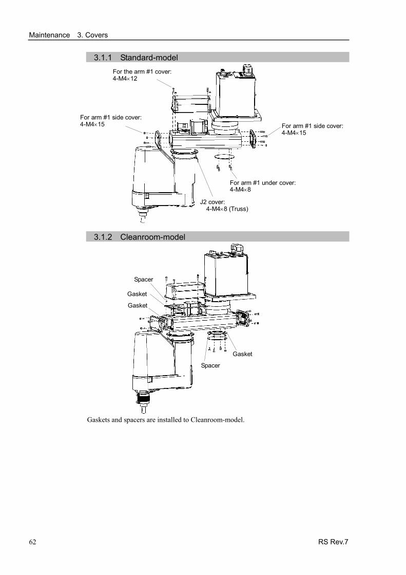
Maintenance 3. Covers
3.1.1 Standard-model
For arm #1 side cover: 4-M4×15
62 RS Rev.7
For arm #1 under cover: 4-M4×8
For the arm #1 cover:4-M4×12
For arm #1 side cover:4-M4×15
J2 cover:4-M4×8 (Truss)
3.1.2 Cleanroom-model
Spacer
Gasket
Spacer
Gasket
Gasket
Gaskets and spacers are installed to Cleanroom-model.
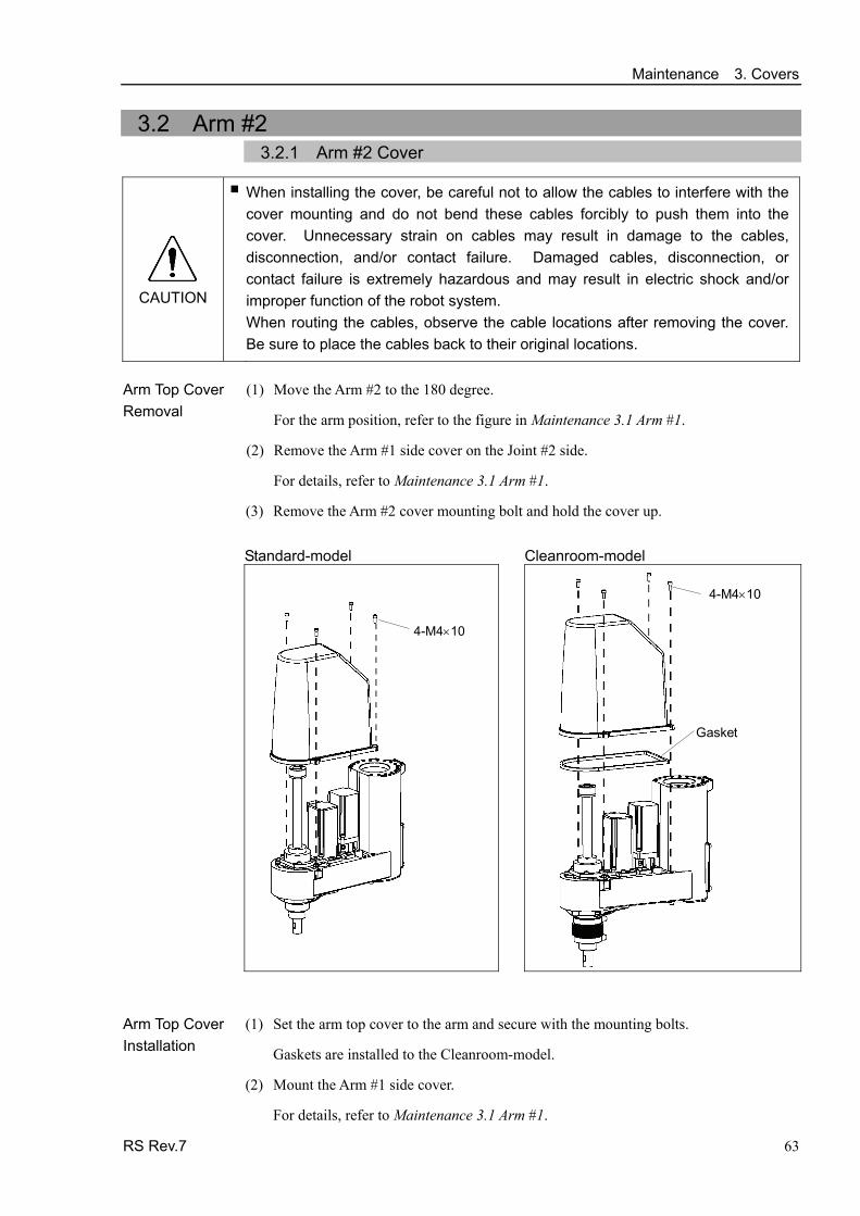
Maintenance 3. Covers
3.2 Arm #2 3.2.1 Arm #2 Cover
CAUTION
■ When installing the cover, be careful not to allow the cables to interfere with the cover mounting and do not bend these cables forcibly to push them into the cover. Unnecessary strain on cables may result in damage to the cables, disconnection, and/or contact failure. Damaged cables, disconnection, or contact failure is extremely hazardous and may result in electric shock and/or improper function of the robot system. When routing the cables, observe the cable locations after removing the cover. Be sure to place the cables back to their original locations. (1) Move the Arm #2 to the 180 degree.
For the arm position, refer to the figure in Maintenance 3.1 Arm #1.
Arm Top Cover Removal
(2) Remove the Arm #1 side cover on the Joint #2 side.
For details, refer to Maintenance 3.1 Arm #1.
(3) Remove the Arm #2 cover mounting bolt and hold the cover up.
Standard-model Cleanroom-model
4-M4×10
Gasket
4-M4×10
Arm Top Cover Installation
(1) Set the arm top cover to the arm and secure with the mounting bolts.
Gaskets are installed to the Cleanroom-model.
(2) Mount the Arm #1 side cover.
For details, refer to Maintenance 3.1 Arm #1.
RS Rev.7 63

Maintenance 3. Covers
64 RS Rev.7
3.2.2 Under Cover
Unscrew the under cover mounting bolts, and then pull the cover downward to remove it.
The under cover may not be removed from the shaft because the end effector is installed. If it is necessary to remove the cover completely (for replacement of the ball screw spline unit etc.), remove the end effector.
When the ball screw spline unit need to be replaced, remove the end effector and removethe under cover completely.
If it is not necessary to remove the cover completely, move the shaft to the lower limit, and lower the under cover. Then, perform maintenance or inspection.
When bellows are installed to the manipulator, remove or pull down the lower bellows andthen remove the under cover. For bellows removal, refer to Maintenance 9. Bellows.
NOTE
Standard-model Cleanroom-model
3-M4×10
Gasket
3-M4×10
A gasket is installed to Cleanroom-model.
3.2.3 Arm #2 Maintenance Cover Unscrew the bolts securing the Arm #2 maintenance cover, and then pull the cover downward to remove it. Standard-model Cleanroom-model
4-M4×8
Gasket
4-M4×8
Gasket is installed to the Cleanroom-model.

Maintenance 3. Covers
3.3 Connector Plate
■ Do not remove the connector plate forcibly. Removing the connector plate forcibly may result in damage to the cables, disconnection, and/or contact failure. Damaged cables, disconnection, or contact failure is extremely hazardous and may result in electric shock and/or improper function of the robot system.
CAUTION
■ When installing the connector plate, be careful not to allow the cables to interfere with the plate mounting and do not bend these cables forcibly to push them into the cover. Unnecessary strain on cables may result in damage to the cables, disconnection, and/or contact failure. Damaged cables, disconnection, or contact failure is extremely hazardous and may result in electric shock and/or improper function of the robot system. When routing the cables, observe the cable locations after removing the connector plate. Be sure to place the cables back to their original locations.
Unscrew the connector plate mounting bolts and remove the plate.
Standard-model Cleanroom-model 8-M4×10
8-M4×10Gasket
Spacer
A gasket and spacer are installed to Cleanroom-model.
RS Rev.7 65
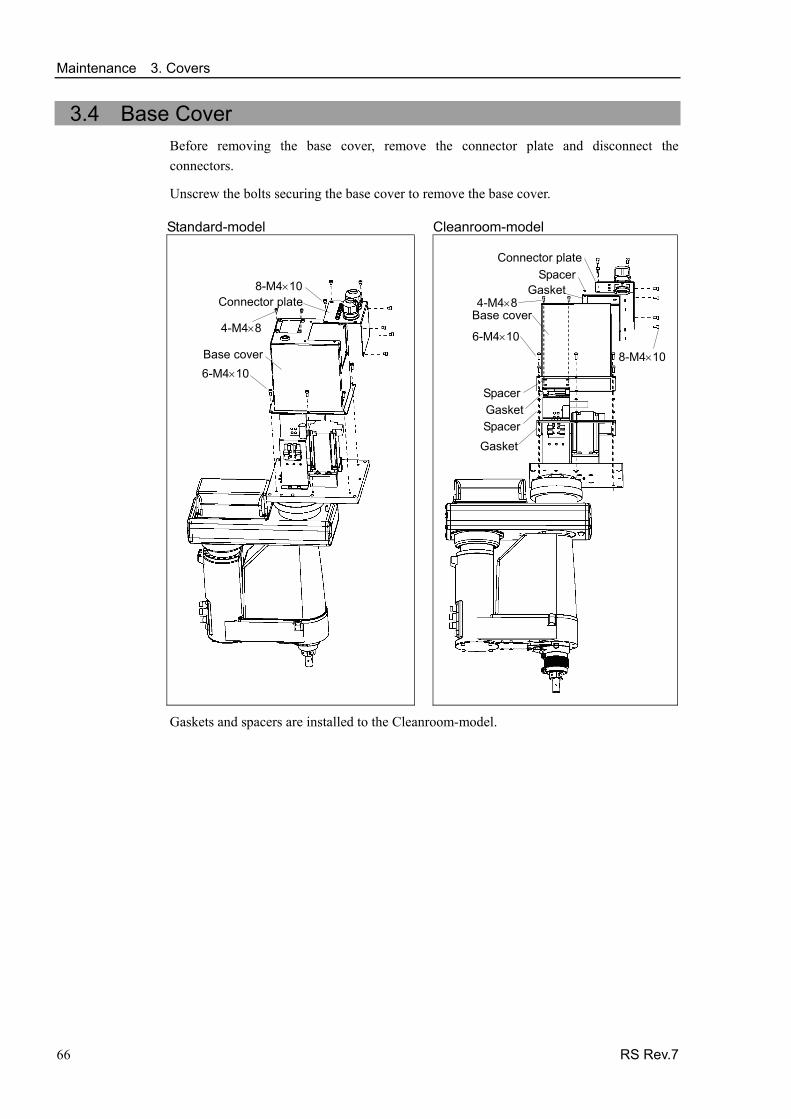
Maintenance 3. Covers
3.4 Base Cover Before removing the base cover, remove the connector plate and disconnect the connectors.
Unscrew the bolts securing the base cover to remove the base cover. Standard-model Cleanroom-model
8-M4×10
Base cover 6-M4×10
Connector plate
4-M4×8
4-M4×8
6-M4×10
Gasket
GasketSpacer
Spacer
Base cover
8-M4×10
Gasket Spacer
Connector plate
Gaskets and spacers are installed to the Cleanroom-model.
66 RS Rev.7
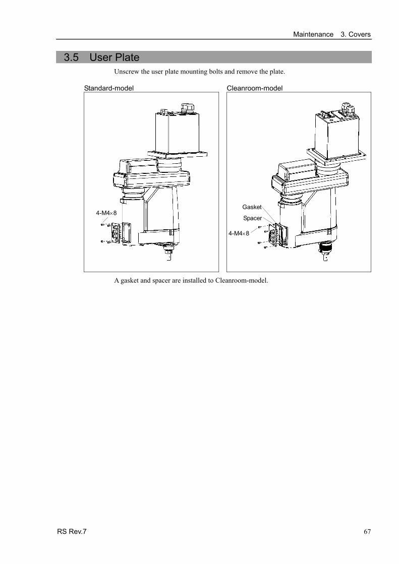
Maintenance 3. Covers
3.5 User Plate Unscrew the user plate mounting bolts and remove the plate.
Standard-model Cleanroom-model
4-M4×8
4-M4×8
Gasket
Spacer
A gasket and spacer are installed to Cleanroom-model.
RS Rev.7 67

Maintenance 4. Cable Unit
68 RS Rev.7
4. Cable Unit ■ Do not insert or pull out the motor connectors while the power to the robot system
is turned ON. Inserting or pulling out the motor connectors with the power ON is extremely hazardous and may result in serious bodily injury as the Manipulator may move abnormally, and also may result in electric shock and/or malfunction of the robot system.
■ To shut off power to the robot system, pull out the power plug from the power source. Be sure to connect the AC power cable to a power receptacle. DO NOT connect it directly to a factory power source.
■ Before performing any replacement procedure, turn OFF the Controller and related equipment, and then pull out the power plug from the power source. Performing any replacement procedure with the power ON is extremely hazardous and may result in electric shock and/or malfunction of the robot system.
WARNING
■ Be careful not to get any foreign substances in the Manipulator, connectors, and pins during maintenance. Turning ON the power to the robot system when any foreign substances exist in them is extremely hazardous and may result in electric shock and/or malfunction of the robot system.
CAUTION
■ Be sure to connect the cables properly. Do not allow unnecessary strain on the cables. (Do not put heavy objects on the cables. Do not bend or pull the cables forcibly.) The unnecessary strain on the cables may result in damage to the cables, disconnection, and/or contact failure. Damaged cables, disconnection, or contact failure is extremely hazardous and may result in electric shock and/or improper function of the robot system.

Maintenance 4. Cable Unit
4.1 Replacing Cable Unit Since the power is supplied to each motor from the lithium battery installed on the battery board via the battery connector, the position data will not be lost when the Controller is turned OFF. When the battery connectors are disconnected, the position data will be lost, and EPSON RC+ will display an error when the Controller is turned ON.
If the error occurs, execute the calibration of all joints and axes.
Name Quantity Note
Cable unit 1 Each manipulator model (Refer to Maintenance: 14. Maintenance parts)
Grease for cable (GPL-224) 10 g R13B030304
Maintenance
parts
Battery Unit (Lithium battery) 3 R13ZA00600300 Hexagonal wrench (width across flats: 3 mm) 1 For M4 screw Hexagonal wrench (width across flats: 4 mm) 1 For M5 screw Hexagonal wrench (width across flats: 5 mm) 1 For M6 screw Spanner (width across flats: 5 mm) 1 For D-sub connector removal Nut screwdriver (width across flats: 5 mm) 1 For D-sub connector removal Nippers 1 For cutting wire tie
Alcohol Proper
quantity For wiping grease
Tools
Wiping cloth 1 For wiping grease Material Wire tie 20
Cable unit 1
Cable unit 2
(Figure: RS3-351S)
RS Rev.7 69
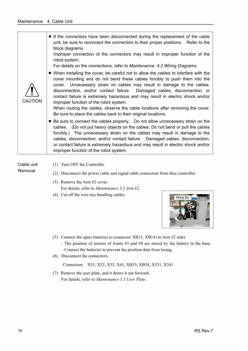
Maintenance 4. Cable Unit
■ If the connectors have been disconnected during the replacement of the cable unit, be sure to reconnect the connectors to their proper positions. Refer to the block diagrams. Improper connection of the connectors may result in improper function of the robot system. For details on the connections, refer to Maintenance: 4.2 Wiring Diagrams.
■ When installing the cover, be careful not to allow the cables to interfere with the cover mounting and do not bend these cables forcibly to push them into the cover. Unnecessary strain on cables may result in damage to the cables, disconnection, and/or contact failure. Damaged cables, disconnection, or contact failure is extremely hazardous and may result in electric shock and/or improper function of the robot system. When routing the cables, observe the cable locations after removing the cover. Be sure to place the cables back to their original locations.
CAUTION
■ Be sure to connect the cables properly. Do not allow unnecessary strain on the cables. (Do not put heavy objects on the cables. Do not bend or pull the cables forcibly.) The unnecessary strain on the cables may result in damage to the cables, disconnection, and/or contact failure. Damaged cables, disconnection, or contact failure is extremely hazardous and may result in electric shock and/or improper function of the robot system.
(1) Turn OFF the Controller. Cable unit
Removal (2) Disconnect the power cable and signal cable connectors from thee controller.
(3) Remove the Arm #2 cover. For details, refer to Maintenance 3.2 Arm #2.
(4) Cut off the wire ties bundling cables.
Wire tie
(5) Connect the spare batteries to connector XB13, XB14 (in Arm #2 side).
- The position of motors of Joints #3 and #4 are stored by the battery in the base. Connect the batteries to prevent the position data from losing.
(6) Disconnect the connectors.
Connectors X31, X32, X33, X41, XB33, XB34, X331, X341
(7) Remove the user plate, and it draws it out forward. For details, refer to Maintenance 3.5 User Plate.
70 RS Rev.7

Maintenance 4. Cable Unit
RS Rev.7 71
(8) Disconnect the air tubes, ground wire, connecter of the D-sub cable (XU11, XU21), and connector of the brake release switch from the user plate.
Press the ring on the fitting and pull out the air tube. (ø6×2, ø4×1)
Be sure to remember the cable location to connect them to the original position.
D-sub cable
Air tube
Brake release switch
(9) Remove the ground wire from the cable mounting jig.
Cut off two wire ties bundling the cables.
(10) Remove the Arm #2 maintenance cover. For details, refer to Maintenance 3.2 Arm #2.
(11) Draw out the cables connected to the motor side forward in order of size with the thinnest one first.
NOTE
Cable
(12) Remove the Arm #1 cover.
For details, refer to Maintenance: 3.1 Arm #1.
(13) Cut off two wire ties bundling the cables.
(14) Disconnect the ground wire.
Wire tie
(15) Pull out the tubes and cables upward in order of size with the thinnest one first.
(Be careful about the connectors not to be caught.)
(16) Remove the Arm #1 side cover and Arm #1 under cover.
For details, refer to Maintenance 3.1 Arm #1.
(17) Connect the spare batteries to connector XB12 (in Arm #2 side). - The position of motor of Joint #2 is stored by the battery in the base.
Connect the batteries to prevent the position data from losing.
(18) Push the cables and tubes drawn out before and pull out the connectors from the hole of the under cover.
(19) Disconnect the connectors except the battery connector.
Connectors X21, X22, X23, X30, XB22, XB23, X221, X231, XU10, XU20
(20) Remove the ground wire.
Ground wire

Maintenance 4. Cable Unit (21) Cut off two wire ties bundling the cables
Pull out the cable unit 2. Wire tie
(22) Remove the Connector plate.
For details, refer to Maintenance: 3.3 Connector plate.
(23) Remove the Base cover.
For details, refer to Maintenance 3.4 Base cover.
(24) Remove the D-sub connector from the plate securing the cables.
(25) Remove three air tubes.
Cut off two wire ties bundling the cables. Wire tie
(26) Pull out the cable unit 2 and air tubes.
(Be careful about the connector not to be caught.)
72 RS Rev.7

Maintenance 4. Cable Unit Cable unit Installation
(1) Mark the position of the cable unit 1 using a permanent marker.
Base sideArm #1 side
RS Rev.7 73
240120 Ground wire 400mm (rough)
350120 Air tube ×3 (rough)
15 120
X121X131
Signal cable (rough)
X221 X231
Heat-shrinkable tube
Greasing point
X20X30X62X63Ground wire
Power cable (rough)
15 120
D-subXU10 XU20
User wire (rough) 15 120
Marking
X21, X22 X23, XB22 XB23, X30
(2) Cover both ends of the cables with plastic bags. (The photo shows the one end covered with plastic bags.)
The plastic bags prevent grease adhesion to the ends of connectors/air tubes during thecable drawing.
Cable
Joint #1
Inserting direction
(3) Insert the cables to the Joint #1 from the base side. Be careful about the cable direction. Refer to the connector label in Step (1).
Insert the connectors in order of size with the largest one first, and then, the air tube and ground wire. To prevent the cables and tube from falling off, pull them out from the bottom side temporarily and apply grease (GPL-224) to the marked point. For the greasing point, refer to Step (1).

Maintenance 4. Cable Unit
74 RS Rev.7
(4) Put two wire ties to the cable mounting jig in Arm #1.
Secure cables, tube, and ground wire loosely.
Secrure the bottom of the tube and ground wire where the grease (GPL-224) is applied.
Wire tie
Heat-shrinkable tube
(5) Connect the connectors to the battery baord of the base side.
Connectors X62, X63
(6) Draw out the connectors of Arm #1 side (X21, X22, XB22, X221) forward in the arm.
(7) Connect the D-sub cable and air tubes connected to the J1 cable plate (inner side).
(8) Push the wires, tubes, and ground wire downward and secure them to the cable mounting plate with the wire tie.
When bundling the cables, untangle the cables and put Arm #1 to the position of 90 degree (end of the arm faces to the other side to the J1 motor.)
Wire tie
(9) Install the ground wire.
(10) Mark the position of the cable unit 2 using a permanent marker.
Arm #2 side
Ground wire 600mm (rough)
150Air tube ×3 (rough)
XU11 XU21
User wire (rough) 300150
XU10 XU20
Arm #1 side Marking
Marking
X231
Signal cable (rough)
X331
X341
Heat-shrinkable tube
300150
X23 XB23 X30 Ground wire
Power cable (rough)
X31, XB33 X32 X41, XB34 300150
150
Greasing point
50
Cable
(11) Insert the cables to the Arm #1.
Be careful about the cable direction. Refer to the connector label in Step (1).

Maintenance 4. Cable Unit (12) Secure the cables with the wire tie.
The wire tie should be a little away from the greasing part of the cables.
Untangle the cables and bundle them at the position of calibration point of Arm #2 (where Arm #1 overlaps with Arm #2).
D-sub cable
Air tube
Brake release switch (13) Connect the ground wire.
(14) Secure the air tubes and cables to both sides of the motor.
(15) Connect the ground wire.
(16) Connect the connectors.
Connectors X21, X22, X23, X30, XB22, XB23, X221, X231, XU10, XU20.
(17) Remove the spare battery from XB12.
Connector
(18) Secure the cables with the wire tie.
(19) Install the ground wire to the connector plate.
(20) Connect the D-sub cable connectors (XU11, XU21) and air tubes connected to the inner side of connector plate.
D-sub cable
Air tube
Brake release switch (21) Put the cable unit 2 to the wire hole of Arm #2
and bundle the cables with the wire tie. Wire tie
(22) Connect the connectors.
Connectors X31, X32, X33, X41, XB33, XB34, X331, X341.
For details, refer to Maintenance 4.2 Wiring Diagrams.
(23) Remove the spare batteries from XB13 and XB14.
RS Rev.7 75

Maintenance 4. Cable Unit
76 RS Rev.7
(24) Mount the user plate to the Arm #2 cover. For details, refer to Maintenance 3.5 User Plate.
(25) Set and secure the Arm #2 cover and Arm #2 maintenance cover without the cables being stuck.
For details, refer to Maintenance 3.2 Arm #2.
(26) Mount the Arm #1 cover, Arm #1 side cover, and Arm #1 under cover.
For details, refer to Maintenance 3.1 Arm #1.
(27) Install the Base cover.
For details, refer to Maintenance 3.4 Base Cover.
(28) Connect the connector and install the connector plate.
For derails, refer to Maintenance 3.3 Connector Plate.
(29) Perform the calibration of all axis.

Maintenance 4. Cable Unit
4.2 Wiring Diagrams
4.2.1 Signal Cable For the colors and symbols of the cables, refer to Maintenance 4.2.2 Power Cable.
Continues to the next page
RS Rev.7 77

Maintenance 4. Cable Unit
78 RS Rev.7
Continued from the previous page

Maintenance 4. Cable Unit
4.2.2 Power Cable
Continues to the next page
Code Cable color Code Cable color
B Black P Pink
BR Brown R Red
G Green V Violet
L Blue W White
O Orange Y Yellow
RS Rev.7 79

Maintenance 4. Cable Unit
80 RS Rev.7
Continued from the previous page

Maintenance 4. Cable Unit
4.2.3 User Cable
Code Cable color Code Cable color
B Black R Red
BR Brown V Violet
G Green W White
L Blue Y Yellow
The following table shows the types of the cable unit.
Environment Code Note
S R13B020028
C R13B020029 Waterproof connector : D-sub
RS Rev.7 81

Maintenance 4. Cable Unit
82 RS Rev.7
4.3 Replacing M/C Cable
Since the power is supplied to each motor from the lithium battery installed on the battery board via the battery connector, the position data will not be lost when the Controller is turned OFF. When the battery connectors are disconnected, the position data will be lost, and EPSON RC+ will display an error when the Controller is turned ON.
NOTE If the error occurs, execute the calibration of all joints and axes. For details, refer to Maintenance: 13. Calibration.
Name Quantity Note
Maintenance parts M/C Cable 1
Each manipulator model (Refer to Maintenance: 14. Maintenance parts)
Hexagonal wrench (width across flats: 3 mm) 1 For M4 screw Tools
Torque wrench 1
■ If the connectors have been disconnected during the replacement of the cable unit, be sure to reconnect the connectors to their proper positions. Refer to the block diagrams. Improper connection of the connectors may result in improper function of the robot system. For details on the connections, refer to Maintenance: 4.2 Wiring Diagrams.
■ When installing the cover, be careful not to allow the cables to interfere with the cover mounting and do not bend these cables forcibly to push them into the cover. Unnecessary strain on cables may result in damage to the cables, disconnection, and/or contact failure. Damaged cables, disconnection, or contact failure is extremely hazardous and may result in electric shock and/or improper function of the robot system. When routing the cables, observe the cable locations after removing the cover. Be sure to place the cables back to their original locations.
CAUTION
■ Be sure to connect the cables properly. Do not allow unnecessary strain on the cables. (Do not put heavy objects on the cables. Do not bend or pull the cables forcibly.) The unnecessary strain on the cables may result in damage to the cables, disconnection, and/or contact failure. Damaged cables, disconnection, or contact failure is extremely hazardous and may result in electric shock and/or improper function of the robot system.
M/C cable

Maintenance 4. Cable Unit
RS Rev.7 83
(1) Turn OFF the Controller. M/C Cable
Removal (2) Disconnect the power cable and signal cable connectors from the controller.
(3) Remove the Connector Plate. For details, refer to Maintenance: 3.3 Connector Plate.
Do not pull the Connector plate forcibly. The M/C cables are still attached to the plate.
(4) Disconnect the connectors. Connector: x10, x20, x30, x111, x121, X131
Each connector has a unique number. Each connector has a different shape.
Do not disconect the buttary connector (X61, X62, X63). Otherwise, the calibration must be executed.
(5) Connect new M/C cable connectors to those of the Cable Unit.
(Connect to the connectors of the Cable Unit with the same number.)
M/C Cable Installation
(6) Mount the Connector Plate. For details, refer to Maintenance: 3.3 Connector Plate.
(7) Connect the power cable and signal cable connectors to the controller.
(8) Turn ON the Controller.
(9) If the connector (X61, X62, X63) falls off from the battery, execute the calibration for Joint #1. For details, refer to Maintenance: 13 Calibration.
NOTE
NOTE
NOTE

Maintenance 5. Arm #1
84 RS Rev.7
5. Arm #1 ■ Do not insert or pull out the motor connectors while the power to the robot system
is turned ON. Inserting or pulling out the motor connectors with the power ON is extremely hazardous and may result in serious bodily injury as the Manipulator may move abnormally, and also may result in electric shock and/or malfunction of the robot system.
■ To shut off power to the robot system, pull out the power plug from the power source. Be sure to connect the AC power cable to a power receptacle. DO NOT connect it directly to a factory power source.
WARNING
■ Before performing any replacement procedure, turn OFF the Controller and related equipment, and then pull out the power plug from the power source. Performing any replacement procedure with the power ON is extremely hazardous and may result in electric shock and/or malfunction of the robot system.
■ Be careful not to apply excessive shock to the motor shaft when replacing the motors. The shock may shorten the life cycle of the motors and encoder and/or damage them.
CAUTION ■ Never disassemble the motor and encoder. A disassembled motor and encoder will cause a positional gap and cannot be used again.
After parts have been replaced (motors, reduction gear units, brakes, timing belts, ball screw spline unit, etc.), the Manipulator cannot operate properly because a mismatch exists between the origin stored in each motor and its corresponding origin stored in the Controller. After replacing the parts, it is necessary to match these origins. The process of aligning the two origins is called “Calibration”. Refer to Maintenance: 13. Calibration to perform the calibration.
(Figure : RS3-351S)
Joint #1 motor
Joint #1 reduction gear unit

Maintenance 5. Arm #1
5.1 Replacing Joint #1 Motor Name Quantity Note
AC Servo Motor (400 W) 1 R13B000607 Maintenance
parts Grease (SK-1A) 13 g R13ZA00330100 Hexagonal wrench (width across flats: 2.5 mm) 1 For M5 set screw, M3 screw Hexagonal wrench (width across flats: 3 mm) 1 For M4 screw Torque wrench M 4 1 Force gauge 1 Belt tension 150 N (15.3 kgf) Suitable cord (Length about 800 mm) 1 For belt tension
Tools
Wiping cloth 1 For wiping grease
(1) Turn ON the Controller. Joint #1 motor Removal
(2) Move the Manipulator Joint #1 to the origin.
(3) Turn OFF the Controller.
(4) Remove the connector plate. For details, refer to Maintenance: 3.3 Connector Plate.
(5) Disconnect the following connectors.
Connectors X10, X20, X30, X111, X121, X131 (Hold the claw to remove.) Connector X61
(6) Remove the base cover. For details, refer to Maintenance: 3.4 Base Cover.
(7) Loosen the J1 belt.
Loosen four bolts on the Joint #1 motor unit. Slide the Joint #1 motor unit toward the Joint #1 side.
4-M4×15+ Washer
Joint #1 motor unit
J1 beltPulley
RS Rev.7 85

Maintenance 5. Arm #1
86 RS Rev.7
(8) Remove the Joint #1 motor unit from the base.
Unscrew the bolts securing the Joint #1 motor plate and pull it upward to remove.
4-M4×15 Joint #1 motor unit
Washer
(9) Remove the pulley from the Joint #1 motor.
2-M5×8 set screw
M5 Brass bushing
Pulley
(10) Remove the motor plate from the Joint #1 motor.
4-M4×15 +washer
Motor plate

Maintenance 5. Arm #1
RS Rev.7 87
Joint #1 motor Installation
(1) Mount the motor plate on the Joint #1 motor. 4-M4×15+washer
Motor plate (2) Mount the pulley to the Joint #1 motor.
Fit the end face of the pulley with the end face of the motor shaft.
Tighten one of the set screws on the flat face of the motor shaft until the screw just touches the surface. Insert a bushing into the other set screw hole to prevent damage to the motor shaft.
Then, tighten both set screws.
2-M5×8set screw
M5 Brass bushing
Pulley
(3) Place the J1 belt around the pulley of the Joint #1
motor unit to secure the unit loosely.
Make sure that the gear grooves of the belt are fit into those of the pulleys completely.
Put the motor cable facing toward the other side of Joint #1.
When securing the motor unit, make sure the unit can be moved by hand, and it will not tilt when pulled. If the unit is secured too loose or too tight, the belt will not have the proper tension.
J1 beltPulley
4-M4×15+ Washer
Joint #1 motor unit
(4) Apply the proper tension to the J1 belt and secure
the Joint #1 motor unit.
To do so, pass a suitable cord or string around the Joint #1 motor unit near its mounting plate. Then, pull the cord using a force gauge or similar tool to apply the specified tension shown in the figure on the right.
J1 belt tension = 150N (15.3kgf)
Force gauge
NOTE

Maintenance 5. Arm #1
88 RS Rev.7
(5) Connect the connector to the battery board
Connector X61
(6) Mount the base cover.
For the details, refer to Maintenance: 3.4 Base Cover.
(7) Connect the following connectors.
Connectors X10, X20, X30, X111, X121, X131
(8) Mount the connector plate.
For details, refer to Maintenance: 3.3 Connector Plate.
(9) Perform the calibration of Joint #1.
For details refer to Maintenance: 13. Calibration.

Maintenance 5. Arm #1
RS Rev.7 89
5.2 Replacing Joint #1 Reduction Gear Unit Name Quantity Note
Reduction Gear Unit (HD25-50) 1 R13B010018(RS3-351*) R13B010029(RS4-551*)
Maintenance
Parts Grease (SK-1A) 40 g R13ZA00330100 Hexagonal wrench (width across flats: 1.5 mm) 1 For M2 screw Hexagonal wrench (width across flats: 3 mm) 1 For M4 screw Hexagonal wrench (width across flats: 5 mm) 1 For M6 screw Torque wrench M4 1 Torque wrench M6 1 Nippers 1 Spatula 1 For applying grease Force gauge 1 Belt tension 150 N (15.3 kgf)Suitable cord (Length about 800 mm) 1 For belt tension
1 For wiping grease (Flange)
Tools
Wiping cloth 1 For wiping grease (Bolt) Material Wire tie 4
■ When removing the Manipulator from the base table, the Manipulator with two or
more people. The Manipulator weights are as follows. Be careful not to get hands, fingers, or feet caught and/or have equipment damaged by a fall of the Manipulator. RS3-351S : approx. 17 kg: 38 lb.
WARNING ■ When removing the Manipulator from the base table, support the Manipulator, and then remove the anchor bolts. Removing the anchor bolts without supporting is extremely hazardous and may result in fall of the Manipulator.
(1) Remove the Manipulator from the base table.
To remove the Manipulator, please observe the WARNING above.
Joint #1 reduction gear unit Removal (2) Remove the Joint #1 motor unit.
Execute the removal steps from (1) to (5) in Maintenance: 5.1 Replacing Joint #1Motor.
(3) Remove the air tube, D-sub cable, ground wire on the J1 cable plate. Cut off the wiretie.
(4) Remove the J1 cable plate.
2-M4×10

Maintenance 5. Arm #1
90 RS Rev.7
(5) Remove the Arm #1 under cover.
For details, refer to Maintenance: 3.1 Arm #1.
(6) Remove the ground wire and connectors in the Joint #1 side of Arm #1.
Ground wire
Wire tie
(7) Cut off two wire tie bundling the cables.
Pull out the Cable unit 1 (except air tubes) from the base side.
When pulling out the cables, first, pull out the air tubes from the Arm #1 side (the other side to the cables).
And pull out from smaller connectors in order from the base side.
Do not try to pull out the cables forcibly. Otherwise, connectors may be stuck, disconnected, or connector pins may fall off.
(8) Remove the Arm #1.
12-M6×20
(9) Remove the reduction gear unit from the base.
Be sure to keep the O ring (S65A). 16-M4×20
O ring (S65A)
(10) Remove the J1 ring falling-off-prevention
screws and remove the J1 ring.
(11) Remove the J1 flange (with Metallic pipe).
Be sure to keep the O ring (S90A).
12-M4×30
J1 flange
J1 ring
O ring(S90A)
2-M2×6 J1 ring falling-off-prevention screw
Reduction gear unit

Maintenance 5. Arm #1
(1) Unpack the new reduction gear unit.
(2) Set the O ring to the O ring (S90A) groove in the J1 flange.
(3) Set the hole on the reduction gear and the tap hole on the J1 flange.
Loosely secure all bolts in a crisscross pattern so that the bolts will be secured evenly. Then, using a torque wrench, tighten each bolt securely in a crisscross pattern at the torque specified in the table below.
12-M4×30
J1 flange
J1 ring
2-M2×6J1 ring falling-off-prevention screw
O ring (S90A)
Reduction gear unit
Joint #1 reduction gear unit Installation
(4) Set the J1 ring and secure the J1 ring falling-off-prevention screws.
Item Bolt type Number of bolts Tightening torque
M4×30 12 600 N⋅cm (61.2 kgf) Joint #1 reduction gear unit
M6×15 8 2200 N⋅cm (22.4 kgf)
(5) Set the O ring to the O ring (S65A) groove in the Base.
(6) Mount the reduction gear unit to the base.
Be sure to keep the O ring.
16-M4×20
O ring (S65A)
(7) Mount the Arm #1.
12-M6×20
(8) Mount the Joint #1 cable plate.
2-M4×10
(9) Insert the cable unit to the Arm #1.
Follow the steps in Maintenance: 4.1 Cable Unit - Installation (1) - (9).
(10) Secure the Joint #1 motor and mount the cover.
Follow the steps in Maintenance: 5.1 Replacing Joint #1 Motor - Installation (4) - (8).
(11) Mount the Manipulator to the base table.
RS Rev.7 91

Maintenance 5. Arm #1
5.3 Replacing J1 Belt (1) Remove the J1 motor unit.
Follow the steps in Maintenance: 5.1 Replacing Joint #1 Motor - Removal (1) - (8).
J1 belt Removal
(2) Remove the J1 belt.
4-M4×15
J1 Motor unit
Washer
J1 belt
(1) Mount the J1 belt to the pulley of the Joint #1 side. J1 belt
Installation (2) Mount the J1 motor unit.
Follow the steps in Maintenance: 5.1 Replacing Joint #1 Motor - Installation (3) - (9).
92 RS Rev.7

Maintenance 6. Arm #2
6. Arm #2
■ Do not insert or pull out the motor connectors while the power to the robot system is turned ON. Inserting or pulling out the motor connectors with the power ON is extremely hazardous and may result in serious bodily injury as the Manipulator may move abnormally, and also may result in electric shock and/or malfunction of the robot system.
■ To shut off power to the robot system, pull out the power plug from the power source. Be sure to connect the AC power cable to a power receptacle. DO NOT connect it directly to a factory power source.
WARNING
■ Before performing any replacement procedure, turn OFF the Controller and related equipment, and then pull out the power plug from the power source. Performing any replacement procedure with the power ON is extremely hazardous and may result in electric shock and/or malfunction of the robot system.
■ Be careful not to apply excessive shock to the motor shaft when replacing the motors.
The shock may shorten the life cycle of the motors and encoder and/or damage them.
CAUTION ■ Never disassemble the motor and encoder. A disassembled motor and encoder
will cause a positional gap and cannot be used again.
After parts have been replaced (motors, reduction gear units, brakes, timing belts, ball screw spline unit, etc.), the Manipulator cannot operate properly because a mismatch exists between the origin stored in each motor and its corresponding origin stored in the Controller.
After replacing the parts, it is necessary to match these origins. The process of aligning the two origins is called “Calibration”. Refer to Maintenance: 13. Calibration to perform the calibration.
(Figure: RS3-351S)
Joint #2 motor
Joint #2 reduction gear unit
RS Rev.7 93

Maintenance 6. Arm #2
6.1 Replacing Joint #2 Motor Name Quantity Note
AC Servo Motor (200W) 1 R13B000614 (RS3-351*) R13B000616 (RS4-551*)
Maintenance
Parts Grease (SK-1A) 6 g R13ZA00330100 Hexagonal wrench (width across flats: 2.5 mm) 1 For M5 set screw Hexagonal wrench (width across flats: 3 mm) 1 For M4 screw Hexagonal wrench (width across flats: 4 mm) 1 For M5 screw Nippers 1 For cutting wire tie Force gauge 1 Belt tension 100 N Suitable cord (Length about 800 mm) 1 For belt tension
Tools
Wiping cloth 1 For wiping grease Material Wire tie 4
Joint #2 motor Removal
(1) Remove the Arm #1 cover. For details, refer to Maintenance: 3.1 Arm #1.
(2) Remove the Arm #1 under cover. For details, refer to Maintenance: 3.1 Arm #1.
(3) Disconnect the following connectors. Connectors X21, X221, XB22 (Hold the claw to remove.)
(4) Loosen the J2 belt.
Loosen four bolts securing the Joint #2 motor unit. Slide the Joint #2 motor unit toward the Joint #2 side.
4-M4×5+ washer
Joint #2 motor unit
J2 belt
Pulley
94 RS Rev.7
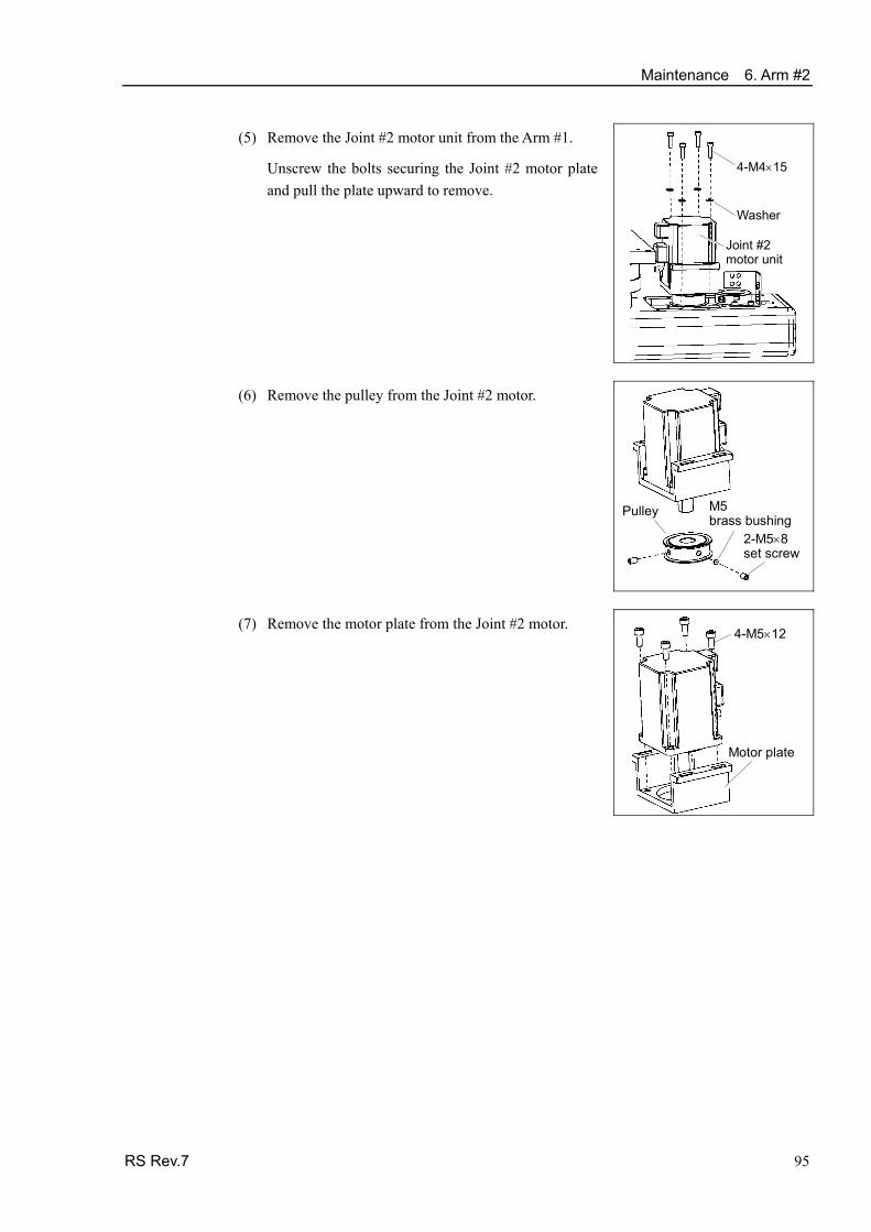
Maintenance 6. Arm #2
RS Rev.7 95
(5) Remove the Joint #2 motor unit from the Arm #1.
Unscrew the bolts securing the Joint #2 motor plate and pull the plate upward to remove.
4-M4×15
Washer
Joint #2motor unit
(6) Remove the pulley from the Joint #2 motor.
2-M5×8set screw
M5brass bushing
Pulley
(7) Remove the motor plate from the Joint #2 motor. 4-M5×12
Motor plate

Maintenance 6. Arm #2
96 RS Rev.7
Joint #2 motor Installation
(1) Mount the motor plate to the Joint #2 motor. 4-M5×12
Motor plate
(2) Mount the pulley to the Joint #2 motor.
Secure the pulley to the distance of 5 mm from the end of the motor shaft.
Tighten one of the set screws on the flat face of the motor shaft until the screw just touches the surface.
Insert a bushing into the other set screw hole to prevent damage to the motor shaft.
Then, tighten both set screws.
2-M5×8 set screw
M5 brass bushing
Pulley
Motor shaft end face
Pulley end face
(3) Set the J2 belt around the pulley of the Joint #2
motor unit and secure the unit loosely.
Make sure the gear grooves of the belt are fit into those of the pulleys completely.
Set the motor cable facing toward the other side to J2 axis.
When securing the unit, make sure that the motor unit can move by hand, and it will not tilt when pulled. If the unit is secured too loose or too tight, the belt will not have the proper tension.
J2 belt
Pulley
4-M4×15
Washer
Joint #2 motor unit
NOTE
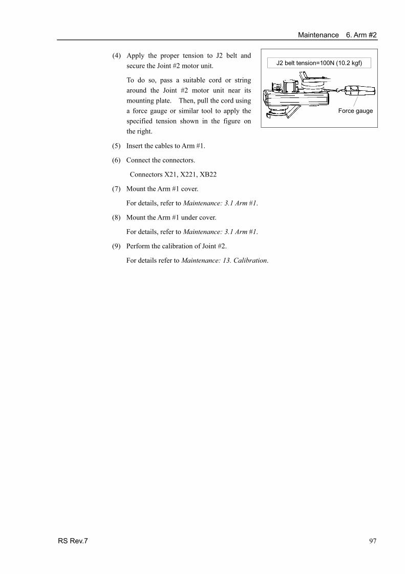
Maintenance 6. Arm #2
RS Rev.7 97
J2 belt tension=100N (10.2 kgf)
Force gauge
(4) Apply the proper tension to J2 belt and secure the Joint #2 motor unit.
To do so, pass a suitable cord or string around the Joint #2 motor unit near its mounting plate. Then, pull the cord using a force gauge or similar tool to apply the specified tension shown in the figure on the right.
(5) Insert the cables to Arm #1.
(6) Connect the connectors.
Connectors X21, X221, XB22
(7) Mount the Arm #1 cover.
For details, refer to Maintenance: 3.1 Arm #1.
(8) Mount the Arm #1 under cover.
For details, refer to Maintenance: 3.1 Arm #1.
(9) Perform the calibration of Joint #2.
For details refer to Maintenance: 13. Calibration.
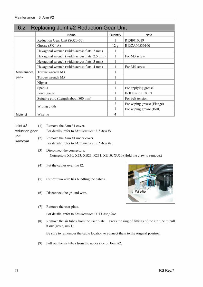
Maintenance 6. Arm #2
98 RS Rev.7
6.2 Replacing Joint #2 Reduction Gear Unit Name Quantity Note
Reduction Gear Unit (SG20-50) 1 R13B010019 Grease (SK-1A) 12 g R13ZA00330100 Hexagonal wrench (width across flats: 2 mm) 1 Hexagonal wrench (width across flats: 2.5 mm) 1 For M3 screw Hexagonal wrench (width across flats: 3 mm) 1 Hexagonal wrench (width across flats: 4 mm) 1 For M5 screw Torque wrench M3 1 Torque wrench M5 1 Nipper 1 Spatula 1 For applying grease Force gauge 1 Belt tension 100 N Suitable cord (Length about 800 mm) 1 For belt tension
1 For wiping grease (Flange)
Maintenance
parts
Wiping cloth 1 For wiping grease (Bolt) Material Wire tie 4
(1) Remove the Arm #1 cover. For details, refer to Maintenance: 3.1 Arm #1.
Joint #2 reduction gear unit Removal
(2) Remove the Arm #1 under cover. For details, refer to Maintenance: 3.1 Arm #1.
(3) Disconnect the connectors: Connectors X30, X23, XB23, X231, XU10, XU20 (Hold the claw to remove.)
(4) Put the cables over the J2.
(5) Cut off two wire ties bundling the cables.
(6) Disconnect the ground wire. Wire tie
(7) Remove the user plate.
For details, refer to Maintenance: 3.5 User plate.
(8) Remove the air tubes from the user plate. Press the ring of fittings of the air tube to pullit out (ø6×2, ø4×1).
Be sure to remember the cable location to connect them to the original position.
(9) Pull out the air tubes from the upper side of Joint #2.

Maintenance 6. Arm #2
RS Rev.7 99
(10) Remove the J2 ring. 2-M4×15M4×20
J2 ring
(11) Remove the J2 cover.
For details, refer to Maintenance: 3.1 Arm #1.
(12) Loosen the J2 belt.
Unscrew four bolts securing the Joint #2 motor unit.
Slide the Joint #2 motor unit toward the Joint #2 side.
4-M4×5+Washer
Joint #2 motor unit
J2 belt
Pulley (13) Remove the screws secured with nuts.
Nut
(14) Use the holes and rotate the Arm #2 to remove the
screws.
16-M3×20
(15) Pull out the cables (except air tube) to downward from Joint #1.
Pull out cables in order of size (smaller cables first).
Do not try to pull out the cables forcibly. Otherwise, connectors may be stuck, disconnected, or connector pins may fall off.

Maintenance 6. Arm #2
100 RS Rev.7
(16) Remove the J2 flange.
Be sure to keep the O ring (S71A).
16-M3×20J2 flange
O ring (S71A)
(17) Remove the reduction gear unit.
Be sure to keep the O ring (S53A).
11-M3×251-M3×30 +M3 Nut
O ring (S53A)
Reductiongear unit

Maintenance 6. Arm #2
(1) Unpack the new reduction gear unit. Apply the grease on the gear.
(2) Set the O ring to the O ring (S71A) groove under the Arm.
Joint #2 reduction gear unit Installation
(3) Secure the reduction gear unit to the Arm #1.
Be sure to keep the O ring.
11-M3×251-M3×30+M3 Nut
O ring(S71A)
Reductiongear unit
Item Bolt type Number of bolts Tightening torque
M3×25 12 300 N⋅cm (30.6 kgf)
M3×30 1 300 N⋅cm (30.6 kgf)Joint #2 reduction gear unit
M3×20 32 300 N⋅cm (30.6 kgf)
(4) Set the O ring (S53A) to the O ring groove in the J2 flange.
(5) Mount the J2 flange.
Be sure to keep the O ring.
16-M3×20J2 flange
O ring(S53A)
(6) Insert the cables to the Arm.
(7) Mount the Arm #2.
16-M3×20
(8) Mount J2 ring.
(9) Insert the air tube to Arm #2 upper side.
Put the cables from above.
2-M4×15M4×20
J2 ring
(10) Connect the air tube to the use r plate and mount the user plate.
For details, refer to Maintenance: 3.5 User Plate.
RS Rev.7 101

Maintenance 6. Arm #2
102 RS Rev.7
(11) Secure the cables with wire tie and connect the ground wire.
(12) Along both sides of the motor, insert the cables and tube in the Arm #1. Wire tie
(13) Connect the connector.
(14) Mount the Arm #1 under cover and J2 cover.
For details, refer to Maintenance: 3.1 Arm #1.
(15) Secure the Joint #2 motor and mount the cover.
Follow the steps in Maintenance: 6.1 Replacing Joint #2 Motor - Installation (4) - (8).
Maintenance 6. Arm #2
RS Rev.7 103
6.3 Replacing J2 Belt J2 belt Removal
(1) Remove the Joint #2 motor unit.
Follow the steps in Maintenance: 6.1 Replacing Joint #2 Motor- Removal (1) - (5).
(2) Pull out the cables.
Follow the steps in Maintenance: 6.2 Replacing Joint #2 Reduction Gear Unit - Removal (2) - (10).
(3) Push the metal pipe for the cable.
(4) Remove the J2 belt.
J2 belt Installation
(1) Mount the J2 belt.
(2) Pull out the pipe for cables to the upper part of the arm.
Follow the steps in Maintenance: 6.2 Replacing Joint #2 Reduction Gear Unit - Installation (8) - (10).
(3) Install the Joint #2 motor unit.
Follow the steps in Maintenance: 6.1 Replacing Joint #2 Motor - Installation (3) - (6).
(4) Follow the steps in Maintenance: 6.2 Replacing Joint #2 Reduction Gear Unit - Installation (11) - (13).
(5) Follow the steps in Maintenance: 6.1 Replacing Joint #2 Motor - Installation (7) - (9).

Maintenance 7. Arm #3
7. Arm #3
■ Do not insert or pull out the motor connectors while the power to the robot system is turned ON. Inserting or pulling out the motor connectors with the power ON is extremely hazardous and may result in serious bodily injury as the Manipulator may move abnormally, and also may result in electric shock and/or malfunction of the robot system.
■ To shut off power to the robot system, pull out the power plug from the power source. Be sure to connect the AC power cable to a power receptacle. DO NOT connect it directly to a factory power source.
WARNING
■ Before performing any replacement procedure, turn OFF the Controller and related equipment, and then pull out the power plug from the power source. Performing any replacement procedure with the power ON is extremely hazardous and may result in electric shock and/or malfunction of the robot system.
■ Be careful not to apply excessive shock to the motor shaft when replacing the
motors. The shock may shorten the life cycle of the motors and encoder and/or damage them.
CAUTION ■ Never disassemble the motor and encoder. A disassembled motor and encoder
will cause a positional gap and cannot be used again.
After parts have been replaced (motors, reduction gear units, brakes, timing belts, ball screw spline unit, etc.), the Manipulator cannot operate properly because a mismatch exists between the origin stored in each motor and its corresponding origin stored in the Controller. After replacing the parts, it is necessary to match these origins.
The process of aligning the two origins is called “Calibration”.
Refer to Maintenance: 13. Calibration to perform the calibration.
(Figure : RS3-351S)
Joint #3 brake
Z belt
Joint #3 motor
104 RS Rev.7

Maintenance 7. Arm #3
RS Rev.7 105
7.1 Replacing Joint #3 Motor Name Quantity Note
Maintenance parts AC Servo Motor (150W) 1 R13B000615
Hexagonal wrench (width across flats: 2.5 mm) 1 For M5 set screw Hexagonal wrench (width across flats: 3 mm) 1 For M4 screw Hexagonal wrench (width across flats: 4 mm) 1 For M5 screw Torque wrench M5 1 Tightening torque 700 N⋅cm Nippers 1 For cutting wire tie Force gauge 1 Belt tension 75 N (7.7 kgf)
Tools
Suitable cord (Length about 800 mm) 1 For belt tension Material Wire tie 4
A brake is mounted on Joints #3 to prevent the shaft from moving down due to the weight of the end effector while the power to the Controller is OFF or while the motor is in OFF status (MOTOR OFF).
Note that the brake will not work during the replacement procedure. Move the shaft down to its lower limit before starting the replacement procedure by following the removal steps from (1) to (4).
(1) Turn ON the Controller. Joint #3 motor
Removal (2) Push down the shaft to its lower limit while pressing the brake release switch. Be sure to keep enough space and prevent the end effector hitting any peripheral equipment.
Be careful of the shaft falling and rotating while the brake release switch is being pressed because the shaft may be lowered by the weight of an end effector.
(3) Turn the Arm #2 to the 180 degree position.
(4) Turn OFF the Controller.
(5) Remove the Arm #1 side cover of the Joint #2 side.
For details, refer to Maintenance: 3.1 Arm #1 Covers.
(6) Remove the Arm #2 cover.
For details, refer to Maintenance: 3.2 Arm #2 Covers.
(7) Cut off the wire tie bundling the motor cables to the Joint #3 motor.
Remember the cable layout so that the cables can be reconnected correctly after replacement.
(8) Disconnect the following connectors. Connectors X331, X31, X32 (Hold the claw to remove.) Connector XB33

Maintenance 7. Arm #3
106 RS Rev.7
(9) Loosen the Z belt.
Loosen four bolts on the Joint #3 motor unit.
Slide the Joint #3 motor unit to the end of the arm.
4-M4×15 + washer
Joint #3 motor unit
(10) Remove the Joint #3 motor unit from Arm #2.
Unscrew the bolts securing the Joint #3 motor unit.
Remove the Z pulley from the Z belt.
Pull the Joint #3 motor unit upward to remove.
Pulley Z belt
Joint #3 motor unit
(11) Remove the brake unit from the Joint #3
motor unit.
Joint #3motor unit 2-M5×8
Brake unit
(12) Unscrew the screws securing the pulley to the
Joint #3 motor. Press the pulley toward the plate.
Remove the brake hub.
Remove the pulley and motor plate.
There is a brass bushing in one of the set screw holes. Be careful not to lose it.
(14) 2-M4×10
(12) 2-M5×8 set screw
Joint #3motor
(12) M5 bushing
Brake hub
Z pulley
Motorplate

Maintenance 7. Arm #3
RS Rev.7 107
Joint #3 motor Installation
(1) Mount the motor plate to the Joint #3 motor. (Be careful of the mounting direction.)
Screw : 2-M4×10 Tightening torque : 350N⋅cm
(2) Insert the pulley and brake hub into the motor shaft. Then, tighten both at a distance of 1 mm from the shaft.
(3) 2-M5×8 set screw
Joint #3 motor
(3) M5 bushing
(1)2-M4×10
Brake hub
Z pulley
Motor plate
1 m
m
Brake hub Shaft
(3) Secure the pulley to the position touching the hub.
Put the one of the set screws and the flatly chamfered surface of motor shaft to touch vertically.
Insert the bushing into the other screw. Secure the bushing to prevent damage from the motor shaft.
(4) Install the brake to the Joint #3 motor.
Align the position of the disk on the brake and the hub.
When the brake disk is not aligned, connect the connector X32. Press the brake release switch and release the brake to manually adjust the position.
Joint #3motor unit 2-M5×8
BrakeUnit
Disk
Hub
4-M4×15 + Washer
Joint #3 motor unit
(5) Put the Joint # 3 motor unit in the arm.
Motor cable must face to the right side of the arm.

Maintenance 7. Arm #3
108 RS Rev.7
(6) Place the Z belt around the Z pulley so that the
gear grooves of the belt are fit into those of the pulley completely.
Pulley Z belt
Joint #3motor unit
(7) Loosely secure the Joint #3 motor unit to Arm #2.
Loosely secure the Joint #3 motor unit to Arm #2 so that the motor unit can be moved by hand, and it will not tilt when pulled. If the unit is secured too loose or too tight,the belt will not have the proper tension.
(8) Apply the proper tension to the Z belt, and then secure the Joint #3 motor unit.
Hexagonal wrench (Stubby type) makes it easier to tighten / remove screws.
Put the M4 wrench to the Joint #3 motor unit, near its mounting plate.
And pass a suitable cord or string around the motor unit.
Then, pull the cord using a force gauge or similar tool to apply the specified tension shown in the figure.
Make sure that the brake cables do not touch the pulley.
4-M4×15 + washer
Z belt tension = 75N (7.7 kgf)
Force gauge
Joint #3 Motor unit
M4 wrench
(9) Connect the following connectors.
Connectors X331, X31, X32, XB33 (10) Re-bundle the cables in their original positions with a wire tie removed in step (7).
Do not allow unnecessary strain on the cables.
(11) Install the Arm #2 cover.
For details, refer to Maintenance: 3.2 Arm #2.
(12) Install the Arm #1 side cove.
For details, refer to Maintenance: 3.1 Arm #1.
(13) Perform the calibration of Joint #3.
For details on the calibration method, refer to Maintenance: 13. Calibration.
NOTE
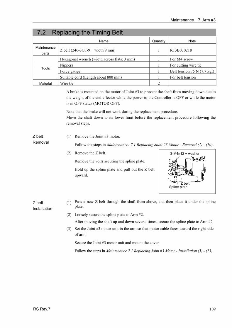
Maintenance 7. Arm #3
7.2 Replacing the Timing Belt Name Quantity Note
Maintenance parts
Z belt (246-3GT-9 width 9 mm) 1 R13B030218
Hexagonal wrench (width across flats: 3 mm) 1 For M4 screw Nippers 1 For cutting wire tie Force gauge 1 Belt tension 75 N (7.7 kgf)
Tools
Suitable cord (Length about 800 mm) 1 For belt tension Material Wire tie 2
A brake is mounted on the motor of Joint #3 to prevent the shaft from moving down due to the weight of the end effector while the power to the Controller is OFF or while the motor is in OFF status (MOTOR OFF).
Note that the brake will not work during the replacement procedure. Move the shaft down to its lower limit before the replacement procedure following the removal steps.
Z belt Removal
(1) Remove the Joint #3 motor.
Follow the steps in Maintenance: 7.1 Replacing Joint #3 Motor - Removal (1) - (10).
(2) Remove the Z belt.
Remove the volts securing the spline plate.
Hold up the spline plate and pull out the Z belt upward.
3-M4×12 + washer
Z belt Spline plate
Z belt Installation
(1) Pass a new Z belt through the shaft from above, and then place it under the spline plate.
(2) Loosely secure the spline plate to Arm #2.
After moving the shaft up and down several times, secure the spline plate to Arm #2.
(3) Set the Joint #3 motor unit in the arm so that motor cable faces toward the right side of arm.
Secure the Joint #3 motor unit and mount the cover.
Follow the steps in Maintenance 7.1 Replacing Joint #3 Motor - Installation (5) - (13).
RS Rev.7 109

Maintenance 7. Arm #3
7.3 Replacing the Brake Name Quantity Note Maintenance
parts Electromagnetic brake 1 R13B030501
Hexagonal wrench (width across flats: 1.5 mm) 1 For M3 set screw Hexagonal wrench (width across flats: 2.5 mm) 1 For M3 screw Hexagonal wrench (width across flats: 3 mm) 1 For M4 screw Hexagonal wrench (width across flats: 4 mm) 1 For M5 screw Nippers 1 For cutting wire tie Force gauge 1 Belt tension 75 N (7.7 kgf)
Tools
Suitable cord (Length about 800 mm) 1 For belt tension Material Wire tie 3
A brake is mounted on the motor of Joint #3 to prevent the shaft from moving down due to the weight of the end effector while the power to the Controller is OFF or while the motor is in OFF status (MOTOR OFF).
Note that the brake will not work during the replacement procedure. Move the shaft down to its lower limit before the replacement procedure following the removal steps.
Electromagnetic Brake Removal
(1) Remove the Joint #3 motor.
Follow the steps in Maintenance: 7.1 Replacing Joint #3 Motor - Removal (1) - (13).
(2) Remove the brake from the brake plate.
2-M3×8
Brake plate
110 RS Rev.7
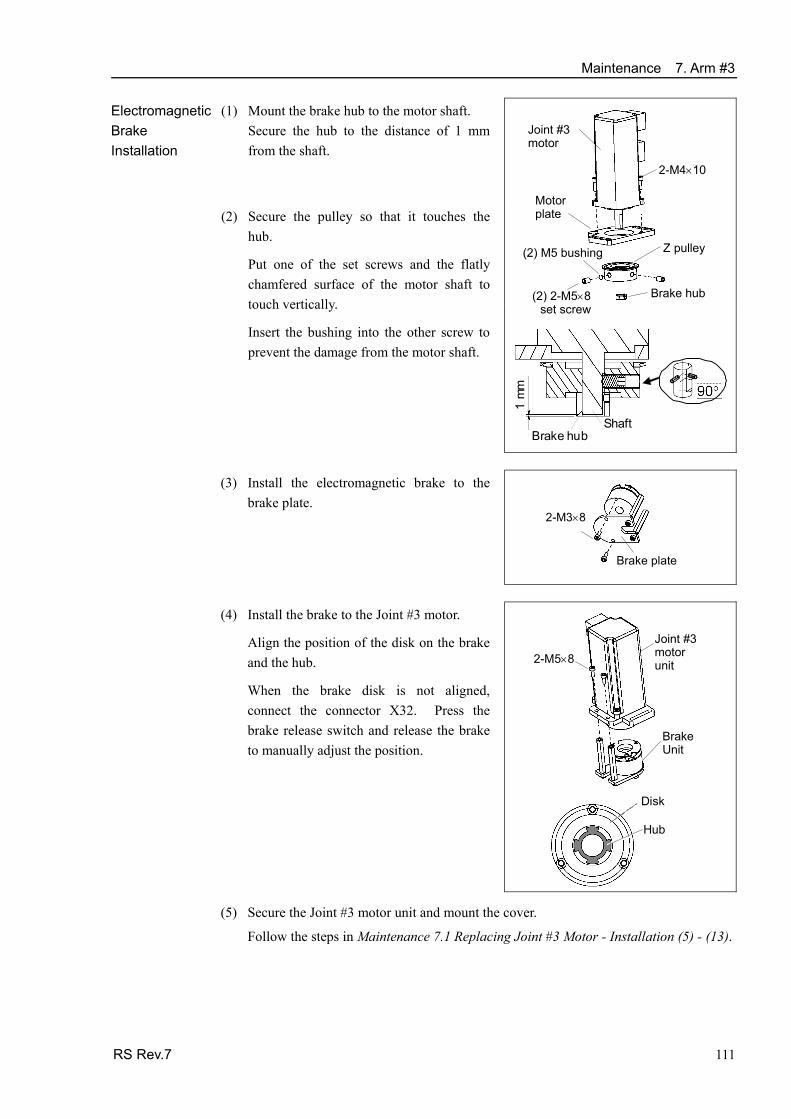
Maintenance 7. Arm #3 Electromagnetic Brake Installation
(1) Mount the brake hub to the motor shaft. Secure the hub to the distance of 1 mm from the shaft.
(2)
(2) 2-M5×8 set screw
Joint #3 motor
(2) M5 bushing
2-M4×10
Brake hub
Z pulley
Motor plate
1 m
m
Brake hub Shaft
Secure the pulley so that it touches the hub.
Put one of the set screws and the flatly chamfered surface of the motor shaft to touch vertically.
Insert the bushing into the other screw to prevent the damage from the motor shaft.
(3) Install the electromagnetic brake to the
brake plate.
2-M3×8
Brake plate
(4) Install the brake to the Joint #3 motor.
Align the position of the disk on the brake and the hub.
When the brake disk is not aligned, connect the connector X32. Press the brake release switch and release the brake to manually adjust the position.
Joint #3motor unit 2-M5×8
BrakeUnit
Disk
Hub
(5) Secure the Joint #3 motor unit and mount the cover.
Follow the steps in Maintenance 7.1 Replacing Joint #3 Motor - Installation (5) - (13).
RS Rev.7 111

Maintenance 8. Arm #4
8. Arm #4
■ Do not insert or pull out the motor connectors while the power to the robot system is turned ON. Inserting or pulling out the motor connectors with the power ON is extremely hazardous and may result in serious bodily injury as the Manipulator may move abnormally, and also may result in electric shock and/or malfunction of the robot system.
■ To shut off power to the robot system, pull out the power plug from the power source. Be sure to connect the AC power cable to a power receptacle. DO NOT connect it directly to a factory power source.
WARNING
■ Before performing any replacement procedure, turn OFF the Controller and related equipment, and then pull out the power plug from the power source. Performing any replacement procedure with the power ON is extremely hazardous and may result in electric shock and/or malfunction of the robot system.
■ Be careful not to apply excessive shock to the motor shaft when replacing the
motors. The shock may shorten the life cycle of the motors and encoder and/or damage them.
CAUTION ■ Never disassemble the motor and encoder. A disassembled motor and encoder
will cause a positional gap and cannot be used again.
After parts have been replaced (motors, reduction gear units, brakes, timing belts, ball screw spline unit, etc.), the Manipulator cannot operate properly because a mismatch exists between the origin stored in each motor and its corresponding origin stored in the Controller. After replacing the parts, it is necessary to match these origins.
The process of aligning the two origins is called “Calibration”.
Refer to Maintenance: 13. Calibration to perform the calibration.
(Figure: RS3-351S)
U axis reduction gear unitU axis belt
Joint#4 motor
112 RS Rev.7

Maintenance 8. Arm #4
RS Rev.7 113
8.1 Replacing Joint #4 Motor Name Quantity Note
Maintenance parts AC Servo Motor (100 W) 1 R13B000617
Hexagonal wrench (width across flats: 2 mm) 1 For M4 set screw Hexagonal wrench (width across flats: 3 mm) 1 For M4 screw Nippers 1 For cutting wire tie Force gauge 1 Belt tension
120 N (12.2kgf)
Tools
Suitable cord (Length about 800 mm) 1 For belt tension
A brake is mounted on the motor of Joint #3 to prevent the shaft from moving down due to the weight of the end effector while the power to the Controller is OFF or while the motor is in OFF status (MOTOR OFF).
Note that the brake will not work during the replacement procedure.
Move the shaft down to its lower limit before starting the replacement procedure by following the removal steps (1) - (4).
(1) Turn ON the Controller. Joint #4 Motor
Removal (2) Push down the shaft to its lower limit while pressing the brake release switch. Be sure to keep enough space and prevent the end effector hitting any peripheral equipment.
Be careful of the shaft falling and rotating while the brake release switch is being pressed because the shaft may be lowered by the weight of an end effector.
(3) Move Arm #2 to the position of 180 degree.
(4) Turn OFF the Controller.
(5) Remove the Arm #1 side cover in the Joint #2 side.
For details, refer to Maintenance: 3.1 Arm #1.
(6) Remove the Arm #2 cover.
For details, refer to Maintenance: 3.2 Arm #2.
(7) Cut off the wire tie used for binding the motor cables to the Joint #4 motor.
Remember the cable location to connect them to the original position.
(8) Remove the following connectors:
Connector X341, X41 (Hold the claw to remove.) Connector XB34
(9) Remove the U belt.
Remove four bolts securing the Joint #4 motor unit.
Slide the motor unit toward the end of arm.
3-M4×15 + washer
Joint #4 motor unit

Maintenance 8. Arm #4
114 RS Rev.7
(10) First, remove the bolts securing the Joint #4 motor unit.
Next, remove the U pulley from the U belt and pull out the motor unit to remove.
U pulley U belt
Joint #4 motor unit
(11) Open the maintenance windows of the Joint #4
reduction gear unit.
Remove the set screw.
Rotate the pulley until the screws fit into the holes.
Maintenance window
Joint #4 motor unit
Remove two set screws.
(12) Remove the Joint #4 motor. 2-M4×15
Joint #4 reduction gear unit
Joint #4 motor
If the motor cannot be removed easily, put a
washer between the motor and reduction gear and use the motor mounting screws to press the motor equally from the reduction gear side to remove the motor.
(Use two diagonal holes from the motor mounting holes. See the photo.)

Maintenance 8. Arm #4
RS Rev.7 115
2-M4×15
Joint #4 reduction gear unit
Joint #4 motor
Joint #4 Motor Installation
(1) Mount the Joint #4 motor to the Joint #4 reduction gear unit.
Align the flat face of the shaft with the hole of the maintenance window.
Screw: 2-M4 × 15 Tightening torque: 350 N⋅cm (35.7 kgf⋅cm)
Maintenance window
Joint #4 motor unit
(2) Align the maintenance holes and screws position by turning the pulley and secure with the set screws.
Close the maintenance windows.
(3) Place the Joint #4 motor unit in the arm so that
the motor cable faces toward the right side of arm.
3-M4×15 + washer
Joint #4 motor unit
(4) Place the U belt around the U pulley so that the gear grooves of the belt are fit into those of the pulley completely.
U pulley U belt
Joint #4 motor unit
(5) Loosely secure the Joint #4 motor unit to Arm #2.
Loosely secure the Joint #4 motor unit to Arm #2 so that the motor unit can be moved by hand, and it will not tilt when pulled. If the unit is secured too loose or too tight, the belt will not have the proper tension.
NOTE

Maintenance 8. Arm #4
116 RS Rev.7
(6) Put M4 wrench to the Joint #4 motor unit near it mounting plate. And pass a suitable cord or string around the motor unit. Then, pull the cord using a force gauge or similar tool to apply the specified tensionshown in the figure.
4-M4×15 + washer
U belt tension = 120 N (12.2 kgf)
Force gauge
Joint #4 motor unit
M4 wrench
Apply the proper tension to the U belt, and then secure the Joint #4 motor unit.
Hexagonal wrench (Stubby type) makes it easier to tighten / remove screws.
(7) Connect the connectors X341, X41, XB34
(8) Re-bundle the cables in their original positions with a wire tie removed in step (7).
Do not allow unnecessary strain on the cables.
(9) Install the Arm #2 cover.
For details, refer to Maintenance: 3.2 Arm #2.
(10) Install the Arm #1 side cover.
For details, refer to Maintenance: 3.1 Arm #1.
Perform the calibration of Joint #4.
For details on the calibration method, refer to Maintenance: 13. Calibration.
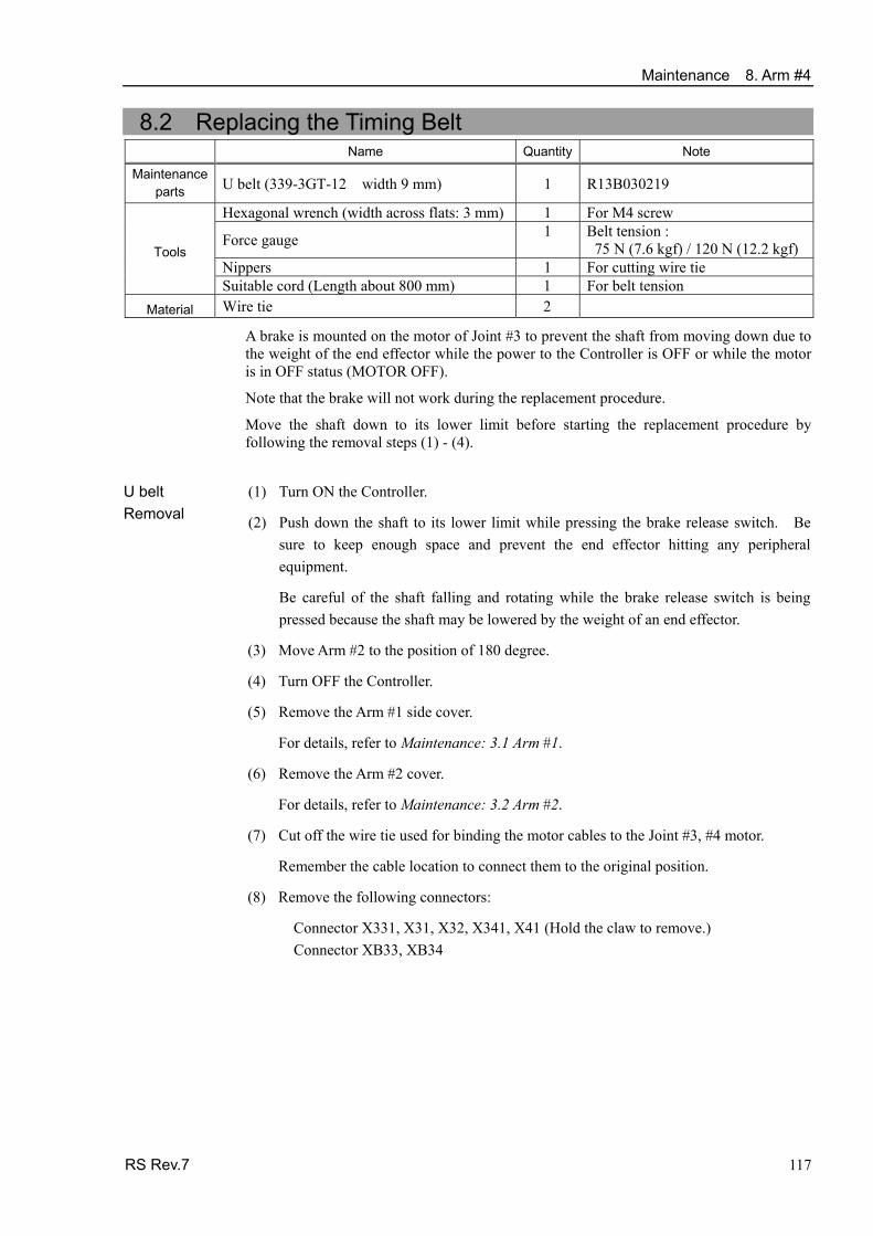
Maintenance 8. Arm #4
RS Rev.7 117
8.2 Replacing the Timing Belt Name Quantity Note
Maintenance parts U belt (339-3GT-12 width 9 mm) 1 R13B030219
Hexagonal wrench (width across flats: 3 mm) 1 For M4 screw
Force gauge 1 Belt tension : 75 N (7.6 kgf) / 120 N (12.2 kgf)
Nippers 1 For cutting wire tie Tools
Suitable cord (Length about 800 mm) 1 For belt tension Material Wire tie 2
A brake is mounted on the motor of Joint #3 to prevent the shaft from moving down due to the weight of the end effector while the power to the Controller is OFF or while the motor is in OFF status (MOTOR OFF).
Note that the brake will not work during the replacement procedure.
Move the shaft down to its lower limit before starting the replacement procedure by following the removal steps (1) - (4).
(1) Turn ON the Controller. U belt
Removal (2) Push down the shaft to its lower limit while pressing the brake release switch. Be sure to keep enough space and prevent the end effector hitting any peripheral equipment.
Be careful of the shaft falling and rotating while the brake release switch is being pressed because the shaft may be lowered by the weight of an end effector.
(3) Move Arm #2 to the position of 180 degree.
(4) Turn OFF the Controller.
(5) Remove the Arm #1 side cover.
For details, refer to Maintenance: 3.1 Arm #1.
(6) Remove the Arm #2 cover.
For details, refer to Maintenance: 3.2 Arm #2.
(7) Cut off the wire tie used for binding the motor cables to the Joint #3, #4 motor.
Remember the cable location to connect them to the original position.
(8) Remove the following connectors:
Connector X331, X31, X32, X341, X41 (Hold the claw to remove.) Connector XB33, XB34

Maintenance 8. Arm #4
4-M4×15 + washer
Joint #3 motor unit
(9) Loosen the Z belt.
Loosen four blots securing the Joint #3 motor unit.
Slide the motor unit toward the end of arm.
(10) Remove the Joint #3 motor unit from Arm #2.
Remove the bolts securing the Joint #3 motor unit.
Remove the Z1 pulley from the Z belt.
Pull out the motor unit to remove.
Pulley Z belt
Joint #3 motor unit
(11) Loosen the U belt.
Loosen the four bolts securing the Joint #4 motor unit.
Slide the Joint #4 motor unit toward the end of arm.
3-M4×15 + washer
Joint #4 motor unit
(12) Remove the Joint #4 motor unit from Arm #2.
First, remove the bolts securing the Joint #4 motor unit.
Next, remove the U pulley from the U belt.
Pull out the Joint #4 motor unit to remove.
U pulley U belt
Joint #4 motor unit
(13) Remove the belt.
Remove the bolts securing the spline plate.
Hold up the spline plate and pull the U belt upward from the shaft.
U belt
3-M4×12 + washer
Spline plate
118 RS Rev.7

Maintenance 8. Arm #4
RS Rev.7 119
U belt Installation
(1) Pass the U belt through the shaft and under the spline plate.
U belt
3-M4×12+ washer
Spline plate
(2) Loosely secure the Spline plate to Arm #2.
Move the shaft up/down several times and secure it.
(3) Set the Joint #4 motor unit to Arm #2 so that the
motor cables face to the right side of arm.
(4) Place the U belt around the U pulley so that the gear grooves of the belt are fit into those of the pulley completely.
3-M4×15 + washer
Joint #4 motor unit (5) Loosely secure the Joint #4 motor unit to Arm #2.
Check that the motor unit can be moved by hand, and it will not tilt when pulled. If the units are secured too loose or too tight, the belt will not have the proper tension.
(6) Apply the proper tension to the U belt, and then secure the Joint #4 motor unit.
To do so, pass a suitable cord or string around the Joint #4 intermediate shaft unit near its mounting plate.
Then, pull the cord using a force gauge or similar tool to apply the specified tension shown in the figure.
4-M4×15 + washer
U belt tension = 120 N (12.2 kgf)
Force gauge
Joint #4 motor unit
M4 wrench
(7) Set the Joint #3 motor unit to Arm #2 so that the
motor cables face to the right side of arm.
4-M4×15+ washer
Joint #3 motor unit
NOTE

Maintenance 8. Arm #4
120 RS Rev.7
(8) Place the Z belt around the Z pulley so that the
gear grooves of the belt are fit into those of the pulley completely.
Pulley Z belt
Joint #3 motor unit
(9) Loosely secure the Joint #3 motor unit to Arm #2.
Check that the motor unit can be moved by hand, and it will not tilt when pulled. If the units are secured too loose or too tight, the belt will not have the proper tension.
(10) Apply the proper tension to the Z belt, and then secure the Joint #3 motor unit.
To do so, pass a suitable cord or string around the Joint #4 intermediate shaft unit near its mounting plate. Then, pull the cord using a force gauge or similar tool to apply the specified tension shown in the figure on the right.
Make sure the brake cable not to touch the pulley.
4-M4×15 + washer
Z belt tension = 75N (7.7 kgf)
Force gauge
Joint #3 Motor unit
M4 wrench
(11) Connect the connectors.
Connector X331, X31, X32, X341, X41, XB33, XB34
(12) Re-bundle the cables in their original positions with a wire tie removed in step (7).
Do not allow unnecessary strain on the cables.
(13) Install the Arm #2 cover.
For details, refer to Maintenance: 3.2 Arm #2.
(14) Install the Arm #1 side cover.
For details, refer to Maintenance: 3.1 Arm #1.
(15) Perform the calibration of Joint #4.
For details on the calibration method, refer to Maintenance: 13. Calibration.
NOTE

Maintenance 8. Arm #4
8.3 Replacing the Reduction Gear Unit Name Quantity Note
Maintenance parts
Reduction Gear Unit 1 R13B010020
Hexagonal wrench (width across flats: 1.3 mm) 1 For M2.5 set screw Hexagonal wrench (width across flats: 2 mm) 1 For M2.5 screw Tools
Nippers 1 For cutting wire tie Material Wire tie 1
Joint #4 reduction gear unit Removal
(1) Remove the Joint #4 motor unit from Arm #2 and remove the motor.
Follow the steps in Maintenance: 8.1 Replacing Joint #4 Motor – Removal (1)-(12).
(2) Remove the reduction gear unit.
Remove the U pulley, and remove the Joint #4 reduction gear unit from U axis plate.
Joint #4 reduction gear unit Installation
(1) Mount the reduction gear unit.
At this point, the maintenance window hole should come to the front of the Arm (the side with no cutout to U axis plate).
3-M4×20
4-M3×15
Joint #4 reduction gear unit
U axis plate
U pulley
(2) Mount the reduction gear unit to the Joint #4 motor and secure to Arm #2.
Follow the steps in Maintenance: 8.1 Replacing Joint #4 Motor – Installation (1)-(12).
RS Rev.7 121

Maintenance 9. Bellows
122 RS Rev.7
9. Bellows A large amount of dust is emitted when replacing the bellows. Take the Manipulator to an outer room such as the room in front of the clean room’s entrance, or take the necessary countermeasures to prevent dust emission before removing the bellows.
NOTE
Name Quantity Note
Bellows 100 mm 1 R13B030705 Maintenance
parts Fluid gasket 1 R13B031241 Tools Cross-point screwdriver 1 For clamp band removal
(1) Remove the end effector. Bellows
Removal (2) Remove the wires and tubes from the end effector.
(3) Turn ON the controller. Stop motor excitation. (MOTOR OFF)
(4) Remove the mechanical stop.
(5) Loosen the cramp band securing above and below the bellows.
BellowsClamp band (big)
Clamp band (small)Mechanical stop
(6) Push up the bellows,
and remove the bearing case and the baring from the shaft.
(7) Pull the bellows, rubber sheet and clamp band from the shaft.
Bellows
Bearing case Mechanical
stop

Maintenance 9. Bellows Bellows Installation
(1) To attach the bellows, move the shaft to its upper limit.
To move the shaft up/down, press and hold the brake release switch. Be sure to keep enough space and prevent the end effector hitting any peripheralequipment.
Be careful of the shaft falling and rotating while the brake release switch is being pressed because the shaft may be lowered by the weight of an end effector.
(2) Pass the shaft through the bellows from the larger joint.
Bellows(cover side)
Secure the cover side of the bellows.
The bellows has two joints: The larger joint must be attached to the cover side. The smaller joint must be attached to the end face side of the shaft. Be careful not to misplace the clamp bands. The clamp band has two sizes; small and large.
Attach the mounting part of the bellows until the end touches the cylindrical part of the cover.
BellowsRubber sheet Clamp band
(3)
Attach the rubber sheet. Be sure to attach the rubber sheet so that no space is made between the bias cut.
Bias cut
Then, secure them with clamp bands.
(4) Apply the fluid gasket uniformly.
- Mating point of the bearing inner race
- Inside of the bearing base
(5) Mount the bearing and the bearing case.
(6) Mount the mechanical stop.
Bearing case
Mechanical stop
Apply thefluid gaskethere
RS Rev.7 123

Maintenance 9. Bellows
Bellows
Bearing case
Mechanical stop
(7) Secure the end face side of the bellows to the shaft.
Cover the bearing case (black) on the end face of the shaft with the bellows mounting part.
Attach the rubber sheet. Be sure to attach the rubber sheet so that no space is made between the bias cut.
Bias cut
Then, secure them with clamp bands.
(8) After completing the attachment of the bellows, move the shaft up/down by handseveral times and rotate Joint #4. Make sure that the bellows can expand andcontract smoothly without any excessive force.
(9) Turn OFF the Controller and peripheral equipment.
(10) Attach the end effector.
(11) Connect the wires and tubes to the end effector.
124 RS Rev.7

Maintenance 10. Ball Screw Spline Unit
RS Rev.7 125
10. Ball Screw Spline Unit
■ Do not insert or pull out the motor connectors while the power to the robot system is turned ON. Inserting or pulling out the motor connectors with the power ON is extremely hazardous and may result in serious bodily injury as the Manipulator may move abnormally, and also may result in electric shock and/or malfunction of the robot system.
■ To shut off power to the robot system, pull out the power plug from the power source. Be sure to connect the AC power cable to a power receptacle. DO NOT connect it directly to a factory power source.
WARNING
■ Before performing any replacement procedure, turn OFF the Controller and related equipment, and then pull out the power plug from the power source. Performing any replacement procedure with the power ON is extremely hazardous and may result in electric shock and/or malfunction of the robot system. After parts have been replaced (motors, reduction gear units, brakes, timing belts, ball screw spline unit, etc.), the Manipulator cannot operate properly because a mismatch exists between the origin stored in each motor and its corresponding origin stored in the Controller. After replacing the parts, it is necessary to match these origins.
NOTE
The process of aligning the two origins is called “Calibration”.
Refer to Maintenance: 13. Calibration to perform the calibration.
10.1 Greasing the Ball Screw Spline Unit Name Quantity Note
Maintenance
parts For Ball Screw Spline Unit (AFB grease)
Proper quantity R13ZA00330200
Wiping cloth 1 For wiping grease (Spline shaft) Tools
Cross-point screwdriver 1 For clamp band removal Only for Cleanroom-model
NOTE Be careful of the shaft falling and rotating while the brake release switch is being pressed
because the shaft may be lowered by the weight of the end effector.

Maintenance 10. Ball Screw Spline Unit
10.1.1 Standard-model (S type) Cover the surrounding area such as the end effector and peripheral equipment in case the grease drips.
(1) Turn ON the Controller. Stop motor excitation. (MOTOR OFF)
(2) Move the Arm #2 to the position of 180 degree.
(3) Move the shaft to its upper limit manually while pressing the brake release switch.
(4) Remove the Arm #1 side cover.
For details, refer to Maintenance: 3.1 Arm #1.
(5) Remove the Arm #2 cover.
For details, refer to Maintenance: 3.2 Arm #2.
(6) Wipe off the old grease from the upper part of the shaft, and then apply new grease to it.
When applying the new grease to the upper part of the shaft, directly fill the grooves on it by hand. Wipe off excess grease from the shaft.
(7) Move the shaft to its lower limit manually while pressing the brake release switch.
(8) Wipe off the old grease from the lower part of the shaft, and apply new grease to it.
When applying the new grease to the lower part of the shaft, directly fill the grooves on it by hand. Wipe off excess grease from the shaft.
(9) Move the shaft up and down several times while pressing the brake release switch tosmooth out the grease on the shaft. Wipe off excess grease from the shaft.
When wiping off the excess grease from the upper part of shaft, turn OFF theController and remove the Arm #2 cover. For details, refer to Maintenance: 3.2 Arm #2.
126 RS Rev.7

Maintenance 10. Ball Screw Spline Unit
10.1.2 Cleanroom-model / Protected-model (C / D with bellows / P type) Cover the surrounding area such as the end effector and peripheral equipment in case the grease drips.
(1) Turn ON the Controller. Stop motor excitation. (MOTOR OFF)
(2) Move the Arm #2 to the position of 180 degree.
(3) Move the shaft to its upper limit manually while pressing the brake release switch.
(4) Wipe off the old grease from the upper part of the shaft, and apply new grease to it.
Directly fill the grooves on the shaft inside the bellows with grease by hand. Wipe off excess grease from the shaft.
Brake release switch
Clamp band
(5) Move the shaft to its lower limit manually while
pressing the brake release switch.
(6) Loosen the clamp band on the bellows, and then move the bellows downward.
Shaft
Clamp band
(7) Wipe off the old grease from the lower part of the shaft, and then apply new grease to it.
Directly fill the grooves on the shaft inside the bellows with grease by hand. Wipe off excess grease from the shaft.
(8) Move the shaft up and down several times while pressing the brake release switch to
smooth out the grease on the shaft. Wipe off excess grease from the shaft.
(9) Secure the bellows.
To attach the bellows, move the shaft to its lower limit. To move the shaft up/down, press and hold the brake release switch.
Attach the mounting part of the bellows until it touches the cylindrical part of thecover.
Bias cut
Then, secure them with clamp bands.
RS Rev.7 127

Maintenance 10. Ball Screw Spline Unit
128 RS Rev.7
10.2 Replacing the Ball Screw Spline Unit Name Quantity Note
R13B010222 (Standard-model) Ball Screw Spline Unit 1
R13B010223 (Cleanroom-model)Maintenance parts
For Ball Screw Spline Unit (AFB grease) Proper
quantity R13ZA00330200
Hexagonal wrench (width across flats: 3 mm) 1 For M4 screw Nippers 1 For cutting wire tie
Force gauge 1 Belt tension 75N (7.6 kgf) / 120 N (12.2 kgf)
Suitable cord (Length about 1000 mm) 1 For belt tension
Tools
Wiping cloth 1 For wiping grease (Spline shaft) Material Wire tie 2

Maintenance 10. Ball Screw Spline Unit
(1) Turn ON the Controller. Ball screw spline unit Removal
(2) Push down the shaft to its lower limit while pressing the brake release switch. Be sure to keep enough space and prevent the end effector hitting any peripheral equipment.
Be careful of the shaft falling and rotating while the brake release switch is being pressed because the shaft may be lowered by the weight of an end effector.
(3) Move Arm #2 to the position of 180 degree.
(4) Turn OFF the Controller.
(5) Detach the wires/tubes from the end effector, and remove the end effector.
(6) This step is only for Cleanroom-model.
Remove the bellows. For details, refer to Maintenance: 9. Bellows.
(7) Remove the Arm #1 side cover and Arm #2 cover.
For details, refer to Maintenance: 3. Covers.
(8) Cut off the wire tie banding motor cables to the motors of Joints #3, #4.
Be sure to remember the cable layout to connect the cables to the original position.
(9) Disconnect the following connectors. Connectors X331, X31, X32, X341, X41 (Hold the claw to remove.) Connector XB33, XB34
(10) Loosen the Z belt.
Loosen four bolts securing the Joint #3 motor.
Slide the Joint #3 motor unit toward the arm end.
4-M4×15 + washer
Joint #3 motor unit
Pulley Z belt
Joint #3 motor unit
(11) Remove the Joint #3 motor unit from Arm #2.
Remove the bolts securing the Joint #3 motor.
Remove the pulley from the Z belt and pull out the Joint #3 motor unit.
RS Rev.7 129

Maintenance 10. Ball Screw Spline Unit
3-M4×15+ washer
Joint #4 motor unit
(12) Loosen the U belt.
Loosen four bolts securing the Joint #4 motor.
Slide the Joint #4 motor unit toward the arm end.
(13) Remove the Joint #4 motor unit from Arm #2.
First, remove the bolts securing the Joint #4 motor.
Next, remove the U pulley from the U belt and pull out the Joint #4 motor unit.
Joint #4 motor unit
U belt U pulley
U belt
3-M4×12 + washer
Spline plate
Z belt
(14) Remove the U belt and Z belt.
Remove the bolts securing the spline plate.
Hold the spline plate upward and pull the U belt and Z belt out of the shaft.
(15) Remove the under cover.
For details, refer to Maintenance: 3.2.Arm #2.
4-M4×12
(16) Remove the nut mounting screws of the ball screw spline shaft on the underside of Arm #2.
(17) Pull the ball screw spline unit out of Arm #2.
130 RS Rev.7

Maintenance 10. Ball Screw Spline Unit
RS Rev.7 131
Ball screw spline unit Installation
(1) Pass the U belt and Z belt through the shaft and mount the ball screw spline unit to Arm #2.
U belt Spline plate
Z belt
(2) Secure the nut mounting screws of the ball
screw spline shaft on lower side of Arm #2.
Be sure to keep the timing belt from being stuck between the nut and Arm #2.
4-M4×12
(3) Secure the under cover.
For details, refer to Maintenance: 3.2.Arm #2.
U belt
3-M4×12 + washer
Spline plate
Z belt
(4) Loosely secure the spline plate to Arm #2.
Secure the spline plate to Arm #2 after moving the shaft up and down several times.
(5) Place the Joint #4 motor unit back to Arm #2. 3-M4×15
+ washer
Joint #4 motor unit
(6) Set the U belt around the U pulley so that the gear grooves of the belt are fit into those of the pulleys completely.
(7) Loosely secure the Joint #4 motor unit to Arm #2.
Check that the motor unit can be moved by hand, and it will not tilt when pulled. If the unit is secured too loose or too tight, the belt will not have the proper tension.
NOTE

Maintenance 10. Ball Screw Spline Unit
132 RS Rev.7
(8) Apply the proper tension to the U belt, and then secure the Joint #4 motor unit.
Hexagonal wrench (Stubby type) makes it easier to tighten / remove the screws.
Put M4 wrench to the Joint #4 motor unit near its mounting plate.
Pass a suitable cord or string around the Joint #4 motor unit. Then, pull the cord using a force gauge or similar tool to apply the specified tension shown in the figure.
4-M4×15 + washer
Z belt tension = 120 N (12.2 kgf)
Force gauge
Joint #4 Motor unit
M4 wrench
(9) Place the Joint #3 motor unit back to Arm #2
so that the motor cable faces toward the right side of arm.
4-M4×15 + washer
Joint #3 motor unit
(10) Put the Z belt around the Z pulley so that the
gear grooves of the belt are fit into those of the pulleys completely.
Pulley Z belt
Joint #3 motor unit
(11) Loosely secure the Joint #3 motor unit to Arm #2.
Check that the motor unit can be moved by hand, and it will not tilt when pulled. If the unit is secured too loose or too tight, the belt will not have the proper tension.
NOTE
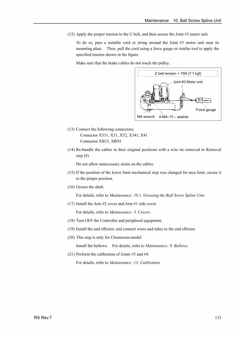
Maintenance 10. Ball Screw Spline Unit (12) Apply the proper tension to the U belt, and then secure the Joint #3 motor unit.
To do so, pass a suitable cord or string around the Joint #3 motor unit near its mounting plate. Then, pull the cord using a force gauge or similar tool to apply the specified tension shown in the figure.
Make sure that the brake cables do not touch the pulley.
4-M4×15 + washer
Z belt tension = 75N (7.7 kgf)
Force gauge
Joint #3 Motor unit
M4 wrench
(13) Connect the following connectors;
Connector X331, X31, X32, X341, X41 Connector XB33, XB34
(14) Re-bundle the cables in their original positions with a wire tie removed in Removal step (8).
Do not allow unnecessary strain on the cables.
(15) If the position of the lower limit mechanical stop was changed for area limit, secure itto the proper position.
(16) Grease the shaft.
For details, refer to Maintenance: 10.1. Greasing the Ball Screw Spline Unit.
(17) Install the Arm #2 cover and Arm #1 side cover.
For details, refer to Maintenance: 3. Covers.
(18) Turn OFF the Controller and peripheral equipment.
(19) Install the end effector, and connect wires and tubes to the end effector.
(20) This step is only for Cleanroom-model.
Install the bellows. For details, refer to Maintenance: 9. Bellows.
(21) Perform the calibration of Joints #3 and #4.
For details, refer to Maintenance: 13. Calibration.
RS Rev.7 133

Maintenance 11. Lithium Battery
11. Lithium Battery ■ Do not insert or pull out the motor connectors while the power to the robot system
is turned ON. Inserting or pulling out the motor connectors with the power ON is extremely hazardous and may result in serious bodily injury as the Manipulator may move abnormally, and also may result in electric shock and/or malfunction of the robot system.
■ To shut off power to the robot system, pull out the power plug from the power source. Be sure to connect the AC power cable to a power receptacle. DO NOT connect it directly to a factory power source.
WARNING
■ Before performing any replacement procedure, turn OFF the Controller and related equipment, and then pull out the power plug from the power source. Performing any replacement procedure with the power ON is extremely hazardous and may result in electric shock and/or malfunction of the robot system.
■ Use meticulous care when handling the lithium battery. Improper handling of
the lithium battery as mentioned below is extremely hazardous, may result in heat generation, leakage, explosion, or inflammation, and may cause serious safety problems.
<Improper Handling> ・Battery Charge
・Disassembly ・Incorrect Installation ・Exposing to Fire
・Forced Discharge ・Deformation by Pressure ・Short-circuit (Polarity; Positive/Negative) ・Heating (85°C or more) ・Soldering the terminal of the lithium battery directly
WARNING
■ When disposing of the battery, consult with the professional disposal services or comply with the local regulation. Spent battery or not, make sure the battery terminal is insulated. If the terminal contacts with the other metals, it may short and result in heat generation, leakage, explosion, or inflammation.
When the lithium battery power is low, an error will occur to warn the user about the low battery status when the Controller is turned ON (when software is started up). When the error occurs, the position data in motors will be lost and all joints need to be completely calibrated again. The life span of the lithium battery is 3 years. Even if the Manipulator is constantly connected to power, the lithium battery needs to be replaced every 3 years. Be sure to use the specified lithium battery and the battery board. (Refer to Maintenance 14: Maintenance Parts List.) Be sure to set the correct polar when installing the battery.
Name Quantity Note Battery unit (Lithium battery) 1 R13ZA00600300 Maintenance
parts Battery board 1 R13B041203 Nippers 1 For cutting wire tie
Tools Hexagonal wrench (width across flats: 3 mm) 1 For M4 screw 1 For fixing battery unit (battery)
Material Wire tie 2 For fixing cable
134 RS Rev.7

Maintenance 11. Lithium Battery
11.1 Replacing the Battery Unit (Lithium Battery)
(1) Turn OFF the Controller.
(2) Remove the connector plate and base cover.
For details, refer to Maintenance: 3.3 Connector Plate and 3.4 Base Cover.
(3) Connect the connectors of the new lithium battery to the battery board.
User the unused connector of the two connectors X60A, X60B on the upper part of the battery board.
Be sure to connect the connector of the new battery before disconnecting the old battery. If the current battery is disconnected before connecting the new battery, the robot will lose the home position data and the calibration must be executed again.
(4) Cut off the wire tie banding the cables of lithium battery.
Battery unit (lithium battery) Removal
(5) Cut off the wire tie banding the lithium battery, Remove the battery.
RS Rev.7 135
X60AX60B
Wire tie
J1 cable plate
Battery board
(1) Mount the new lithium battery to the battery board.
Battery unit (lithium battery) Installation
(2) Fix the cable of lithium battery and connector cable connecting to battery board with wire tie. Refer to the procedure (3).
(3) Mount the base cover and connector plate. For details, refer to Maintenance: 3.3 Connector Plate and 3.4 Base Cover.
(4) Turn ON the Controller.
(5) Check if the Manipulator moves to points (poses) correctly.
To do so, select 2 points (poses) or more from the registered points (poses) and movethe Manipulator to the points (poses).
(6) If the Manipulator does not move to the points (poses) correctly, perform the calibration of all joints and axes.
For details, refer to Maintenance: 13. Calibration.

Maintenance 11. Lithium Battery
11.2 Replacing the Battery Board After battery board and parts have been replaced (motors, reduction gear units, brakes, timing belts, ball screw spline unit, etc.), the Manipulator cannot operate properly because a mismatch exists between the origin stored in each motor and its corresponding origin stored in the Controller. After replacing the parts, it is necessary to match these origins.
The process of aligning the two origins is called “Calibration”.
Refer to Maintenance: 13. Calibration to perform the calibration.
(1) Turn OFF the Controller. Battery board Removal (2) Remove the connector plate and base cover.
For details, refer to Maintenance: 3.3 Connector Plate and 3.4 Base Cover.
(3) Disconnect the following connectors from the battery board.
Connectors X60, X61, X62, X63, X64
X61
X62X63
X64
X60B X60A
Battery board
(4) Loosen the screws securing the battery board and remove the battery board.
(5) Cut the wire tie securing the battery and remove the battery.
Battery board
Battery board Installation
(1) Mount the new battery board and secure it with screws.
Connect the following connectors to the battery board.
(2)
Connectors X60, X61, X62, X63, X64
X61
X62X63
X64
X60B X60A
Battery board (3) Mount the battery to Arm #1 cable plate and
secure it.
(4) Mount the base cover and connector plate. For details, refer to Maintenance: 3.3 Connector Plate and 3.4 Base Cover.
(5) Turn ON the Controller.
(6) Perform the calibration of all joints. For details, refer to Maintenance: 13. Calibration.
136 RS Rev.7

Maintenance 12. LED Lamp
12. LED Lamp ■ Do not insert or pull out the motor connectors while the power to the robot system
is turned ON. Inserting or pulling out the motor connectors with the power ON is extremely hazardous and may result in serious bodily injury as the Manipulator may move abnormally, and also may result in electric shock and/or malfunction of the robot system.
■ To shut off power to the robot system, pull out the power plug from the power source. Be sure to connect the AC power cable to a power receptacle. DO NOT connect it directly to a factory power source.
WARNING
■ Before performing any replacement procedure, turn OFF the Controller and related equipment, and then pull out the power plug from the power source. Performing any replacement procedure with the power ON is extremely hazardous and may result in electric shock and/or malfunction of the robot system.
Name Quantity Note
Maintenance parts
LED Lamp 1 R13A030004
Tools Hexagonal wrench (width across flats: 3 mm) 1 For M4 screw LED Lamp Removal
(1) Remove the Arm #1 under cover.
For details, refer to Maintenance: 3.1 Arm #1 Cover.
(2) Disconnect the connector X22 from the LED.
(3) Remove the LED. Turn it counterclockwise to remove.
Connector X22
LED
LED Lamp Installation
(1) Pass the cable through the LED mounting hole and connect the following connector.
Connector X22
(2) Secure the LED to the Arm #1.
(3) Mount the Arm #1 under cover.
For details, refer to Maintenance: 3.1 Arm #1 Cover.
RS Rev.7 137

Maintenance 13. Calibration
138 RS Rev.7
13. Calibration
13.1 About Calibration
After parts have been replaced (motors, reduction gear units, timing belts, etc.), the Manipulator cannot execute the positioning properly because a mismatch exists between the origin stored in each motor and its corresponding origin stored in the Controller. After replacing the parts, it is necessary to match these origins.
The process of aligning the two origins is called “Calibration”. Note that calibration is not the same as teaching*.
*: “Teaching” means to teach the Controller coordinate points (including poses) anywhere in the operating area of the Manipulator.
■ To ensure safety, a safeguard must be installed for the robot system.
For details on the safeguard, refer to EPSON RC+ User’s Guide: 2.4 Installation and Design Precautions.
WARNING
■ Before operating the robot system, make sure that no one is inside the safeguarded area. The robot system can be operated in the mode for teaching even when someone is inside the safeguarded area. The motion of the Manipulator is always in restricted (low speeds and low power) status to secure the safety of an operator. However, operating the robot system while someone is inside the safeguarded area is extremely hazardous and may result in serious safety problems in case that the Manipulator moves unexpectedly.
Command Input Calibration procedures include the process to input commands. Select EPSON RC+ menu-[Tools]-[Command Window] to use the command window.
The information above is omitted in the calibration procedure. Jog Motion The process to set the jog motion is included in the [Jog & Teach] page of the Robot Manager. Select EPSON RC+ menu-[Tools]-[Robot Manager] and select the [Jog & Teach] tab to use the [Jog & Teach] page.
The page above is indicated as [Jog & Teach] in the calibration procedure.
In the following calibration procedure, it uses EPSON RC+ 5.0. When the procedure is different for each type of software, see your software type. EPSON
RC+ 5.0 EPSON
RC+ 6.0

Maintenance 13. Calibration
RS Rev.7 139
13.2 Calibration Procedure
EPSON RC+ has a wizard for calibration.
This section indicates the calibration using the calibration wizard of EPSON RC+.
You can also calibrate with option TP1 in TEACH mode. For details, refer to RC170/RC180 option Teach pendant TP1 manual, Operation: 2.7 Calibrating Origin: E2 Series / G Series / RS series.
EPSON RC+ 5.0
The same calibration procedure is used for each joint. The follow the steps below are calibration using Joint #1. Follow the steps below to calibrate other joints.
When coordinates for the Manipulator working point require calculation, it is important for Joint #2 to be calibrated accurately. Execute the procedure in “Calibration Using Right / Left Arm Orientations” to accurately calibrate Joint #2. For details, refer to Maintenance: 13.3 Accurate Calibration of Joint #2.
When calibrating Joint #4, you must calibrate Joint #3 and #4 at the same time. You cannot calibrate Joint #4 alone because of the structure of the Manipulator.
The reference point (a point to identify the position of the manipulator) needs to be specified for calibration.
NOTE
(1) Start the calibration wizard.
i. Select EPSON RC+ menu-[Setup]-[Controller] to display the [Controller] dialog.
EPSON RC+ 5.0
ii. Select [Robot]-[Calibration] to display [Robot Calibration].
iii. Select the joint and click the <Calibrate…> button.
i. Select EPSON RC+ 6.0 menu-[Setup]-[System Configuration]. EPSON RC+ 6.0
ii. Select the [Robot]-[Robot**]-[Calibration].
NOTE Only selected robot can be calibrated.

Maintenance 13. Calibration
140 RS Rev.7
iii. Select the joint and click the <Calibrate…> button.
(2) Confirm the warning message and click the <Yes> button.
(3) Move the joint to calibrate manually to approximate zero position (Joint #1: 90 deg.), as shown in the dialog. After moving the joint click the <Next> button.

Maintenance 13. Calibration 90 deg. position of Joint #1:
position aligned with Y-axis in Robot coordinate system
0 pulse position of Joint #2: position where Arm #2 is inner side of Arm #1 (Regardless of the Joint #1 direction)
Arm #2 Arm #1
Base
0 pulse position of Joint #3:
upper limit position in motion range
The height of Joint #3 depends on manipulator model.
Standard model Creanroom model
Upper limit:0 pulse
Turn the shaft flat surface tothe inner side of Arm
0 pulse position of Joint #4: position where the flat surface (or groove in mechanical stop) on the shaft faces toward the inside of Arm #2
Groove
Flat surface
0 pulse
View fromthis direction
RS Rev.7 141

Maintenance 13. Calibration
142 RS Rev.7
(4) Click the <Yes> button to reset the encoder.
* This window will disappear when the Controller starts up.
(5) Reboot the Controller.
* This window will disappear when the Controller starts up.
(6) Select the reference point to use for calibration, and click the <Next> button.
(7) Click the <Jog…> button to display the [Jog & Teach] dialog.

Maintenance 13. Calibration
RS Rev.7 143
(8) Jog the end effector to approximate reference point in the [Jog & Teach] dialog for rough calibration. Then click the <OK> button.
(9) Click the <Next> button.

Maintenance 13. Calibration
144 RS Rev.7
(10) The manipulator moves to the reference point. Click the <Execute> button.
(11) Confirm the message and click the <Yes> button.
(12) After the manipulator moves to the reference point, click the <Next> button.
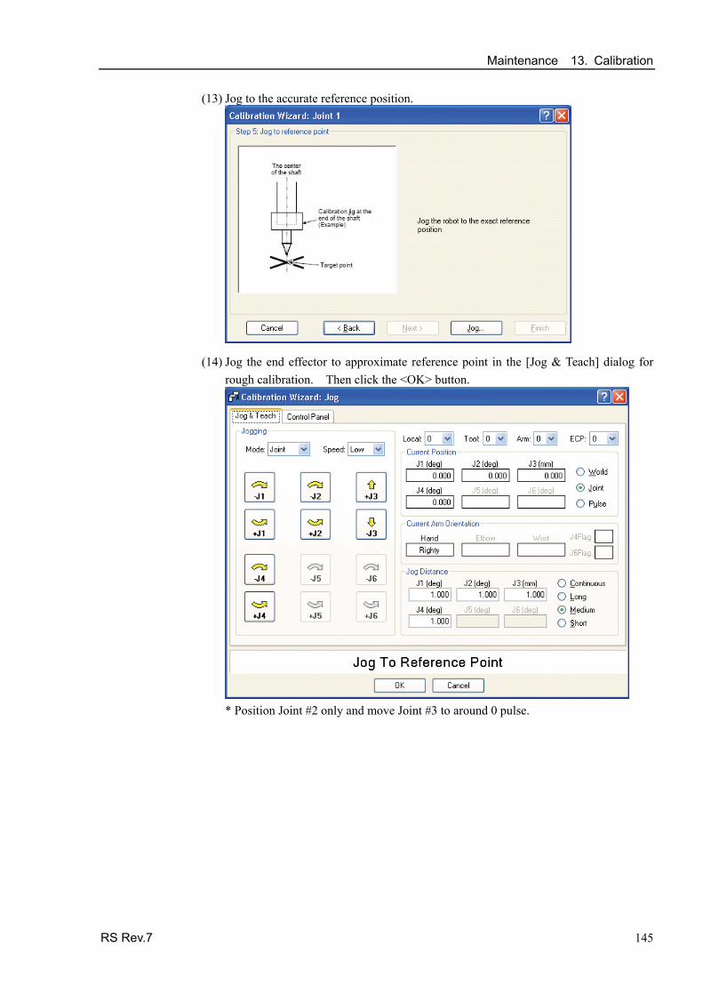
Maintenance 13. Calibration
RS Rev.7 145
(13) Jog to the accurate reference position.
(14) Jog the end effector to approximate reference point in the [Jog & Teach] dialog for rough calibration. Then click the <OK> button.
* Position Joint #2 only and move Joint #3 to around 0 pulse.

Maintenance 13. Calibration
146 RS Rev.7
(15) Click the <Next> button.
(16) Execute the procedures in “Calibration Using Right / Left Arm Orientations” to accurately calibrate Joint #2. Go on to the step (17) for the other joints calibration.
i. Move to another point that has different pose (from righty to lefty) using Jump command. Click the <Yes> button.
ii. Jog to the accurate reference position.

Maintenance 13. Calibration
RS Rev.7 147
iii. Jog to the accurate reference position and adjust the position. Click the <OK> button.
iv. Click the <Next> button.

Maintenance 13. Calibration
148 RS Rev.7
(17) Calibration is complete. Click the <Finish> button.

Maintenance 13. Calibration
RS Rev.7 149
13.3 Accurate Calibration of Joint #2
When coordinates for the Manipulator working point require calculation, it is important for Joint #2 to be calibrated accurately.
NOTE If the accuracy of Joint #2 is not obtained through the steps in the section 13.2 Calibration Procedure, follow the steps below “Calibration Using Right / Left Arm Orientations” to accurately calibrate Joint #2.
The reference point is the center of the ballscrew spline shaft during this calibration.
When there is a misalignment between thecenter of the end effector and the center of theball screw spline shaft, remove the end effectorand perform the calibration of the shaft.
The center of the shaft
There is a misalignment between the center of the end effector and the center of the shaft.
Make a calibration jig as shown in the rightfigure and attach it on the end of the shaft tomake the center of the shaft clear.
Decide a target point and mark a cross (×) on it so that you can easily verify the center of the shaft after switching the arm pose between rightand left.
Calibration jig at the end of the shaft (Example)
Target point
The center of the shaft
After removing the end effector and performing the calibration, install the end effector and move the Manipulator to the teaching point to verify whether there is a positional gap. If there is a positional gap, fine-tune the installation position of the end effector and teach the point again.
Coordinates for the working point requires calculation in the following cases:
· Teaching the working point by entering the coordinate values (MDI teaching)
· Switching the arm orientation between right and left at a given point
· Using the Pallet command
· Executing CP control (such as liner or circular interpolation)
· Using the Local command
· Pose data specified with relative coordinates <Example: P1+X(100) >
· Vision Guide camera calibrations

Maintenance 13. Calibration
150 RS Rev.7
Calibration Using Right / Left Arm Orientations (1) Check the point data for calibration
Use a pose (point) you can easily verify the accuracy within the work envelop ofboth right and left arm. Then, check the number of pose (point) you want to use.
(2) Open the Tools menu | Robot Manager | Control Panel and click the MOTOR ON.
(3) Click the Free All to free all joints from servo control. Now, you can move arms by hands.
(4) Move the arms to the position of point data for calibration in rightly arm orientation.
(5) From the current position, teach any point data number unused. This pose (point) is now called P1.
Specify the point number “1” and click the <Teach> button in the [Jog & Teach].
(6) Click the Lock All in the [Control Panel] to lock all joints under servo control.
(7) Switch to the lefty arm orientation. Then, move the arm to the same point.
>Jump P1/L:Z(0) ' Change the arm orientation from righty to lefty Z is the maximum position
* If there is interference on the way from right to lefty, click the Free All in the[Control Panel] and change the arm orientation to lefty by hands. Then, go to thestep (6), (7).
(8) The joints are slightly out of position.
Adjust the gap with the −Z in the Jogging group in the [Jog & Teach]. Then, teachanother point data number unused. This pose (point) is now called P2.
Specify point number “P2” and click the <Teach> button in [Jog & Teach].
(9) Input the new Hofs value.
>Hofs Hofs (1), Hofs (2) + (Ppls(P1,2) + Ppls(P2,2)) / 2,Hofs(3), Hofs(4)
(10) From the current lefty arm orientation (the position in the step (8)), teach the point data number used in the step (8). This pose (point) is called P2.
Specify point number “P2” and click the <Teach> button in [Jog & Teach].
(11) Switch to the righty arm orientation. Then, make sure the manipulator move to thecorrect position.
>Jump P2/R ' Change the arm orientation from lefty to righty
* If there is any interference on the way from lefty to righty, click the Free All in the[Control Panel] and change the arm orientation to righty by hands. Then, go tothe step (6), (11).
(12) Move the manipulator to other point data and make sure it moves to the correct position. Teach some more points if required.
* Delete the two points taught for the Joint #2 calibration.

Maintenance 13. Calibration
RS Rev.7 151
13.4 Calibration Procedure without using Calibration Wizard
This section indicates the calibration without using the calibration wizard of EPSON RC+. For details of calibration using the calibration wizard, refer to 13.2 Calibration Procedure.
NOTE
When coordinates for the Manipulator working point require calculation, it is important for Joint #2 to be calibrated accurately. Execute the procedure in “Calibration Using Right / Left Arm Orientations” to accurately calibrate Joint #2. For details, refer to Maintenance: 13.3 Accurate Calibration of Joint #2. You cannot calibrate Joint #4 alone because of the structure of the Manipulator. When calibrating Joint #4, you must calibrate Joint #3 and #4 at the same time. The reference point (a point to identify the position of the manipulator) needs to be specified for calibration.
NOTE
Follow steps 1 to 6 described below in order to calibrate the origin.
1. Basic Pose Confirmation
(1)-1 After the part replacement, perform the calibration using the point data currently registered. Confirm the point data number (P*) to reconstruct the correct manipulatorposition.
* Point data before the parts replacement (motor, reduction gear, belt, etc.) is necessary for the calibration.
2. Part Replacement
(2)-1 Replace parts as dictated by this manual. Be careful not to injure yourself or damage parts during part replacement.
3. Encoder Initialization
(3)-1 Turn ON the Controller when all joints are in the motion range.
(3)-2 Manually move the joint that needs origin alignment to its approximate 0 pulse position.

Maintenance 13. Calibration
152 RS Rev.7
90 deg. position of Joint #1:
position aligned with Y-axis in Robot coordinate system
0 pulse position of Joint #2: position where Arm #2 is inner side of Arm #1 (Regardless of the Joint #1 direction)
Arm #2 Arm #1
Base
0 pulse position of Joint #3:
upper limit position in motion range
The height of Joint #3 depends on manipulator model.
Standard model Creanroom model
Upper limit:0 pulse
Turn the shaft flat surface tothe inner side of Arm
0 pulse position of Joint #4: position where the flat surface (or groove in mechanical stop) on the shaft faces toward the inside of Arm #2
Groove
Flat surface
0 pulse
View fromthis direction

Maintenance 13. Calibration
RS Rev.7 153
(3)-3 Connect EPSON RC+ to the Controller.
Select a robot to be calibrated. Input as below in the [Command Window] and execute it. (This example uses “robot 1”.)
> robot 1
(3)-4 Execute the absolute encoder initialization command.
Input one of the following commands to [Command Window] according to the joint being calibrated.
Joint #1: >EncReset 1 Joint #2: >EncReset 2 Joint #3: >EncReset 3 Joint #4: >EncReset 3, 4
(3)-5 Reboot the Controller.
Select EPSON RC+ menu-[Tools]-[Controller] and click the <Reset Controller> button.
* This window will be disappeared when the Controller starts up.
4. Rough Calibration
(4)-1 Turn ON the motor from EPSON RC+ menu-[Tools]-[Robot Manager]- [Controller Panel].
(4)-2 Click the <Free All> button in the [Control Panel] page to free all joints and movethe arms manually.
(4)-3 Move the Manipulator to the approximate position and orientation.
(4)-4 To perform temporary calibration, input the pulse value of the specified point data.When the specified point data is “P1,” input and perform the following commandto [Command Window] according to the joint being calibrated.
> Calpls Ppls(P1,1), Ppls(P1,2), Ppls(P1,3), Ppls(P1,4)
EPSON RC+ 6.0

Maintenance 13. Calibration
154 RS Rev.7
(4)-5 Perform the temporary calibration.
Input and perform one of the following commands to [Command Window] according to the joint being calibrated.
Joint #1: >Calib 1 Joint #2: >Calib 2 Joint #3:: >Calib 3 Joint #4: >Calib 3, 4
5. Calibration (Accurate Positioning)
(5)-1 Click the <Lock All> button in [Control Panel] to put all joints back under servo control.
(5)-2 Move the joint to the specified point using a motion command.
For example, when the specified point data is “P1”, click <MOTOR ON> button in [Control Panel] and execute “Jump P1:Z(0)” from [Jog & Teach].
* The joint NOT being calibrated moves to the original position.
(5)-3 Accurately align the joint* being calibrated to the specified point using jog commands.
* You must move Joint #3 and #4 to the position when calibrating Joint #4.
Select the jog mode [Joint] from [Jog & Teach] to execute the jog motion.
(5)-4 Perform the calibration.
Input and perform one of the following commands to [Command Window] according to the joint being calibrated.
Joint #1: >Calib 1 Joint #2: >Calib 2 Joint #3: >Calib 3 Joint #4: >Calib 3, 4
6. Accuracy Testing
(6)-1 Move the Manipulator to another point to confirm that it moves to the same position. If it does not move to the same position, re-calibrate using another point. You must set the point again if reproducibility cannot be assured through calibration.

Maintenance 14. Maintenance Parts List
RS Rev.7 155
14. Maintenance Parts List
14.1 Common Parts Part Name Code Note
Reference: Maintenance
Joint #1 R13B000616 400 W 5.1
R13B000614 200 W / RS3-351* Joint #2
R13B000616 400 W / RS4-551* 6.1
Joint #3 R13B000615 150 W 7.1
AC Servo Motor
Joint #4 R13B000617 100 W 8.1
R13B010018 RS3-351* Joint #1
R13B010029 RS4-551* 5.2
Joint #2 R13B010019 6.2
Reduction Gear Unit
Joint #3 R13B010020 8.3
Electromagnetic Brake
Joint #3 R13B030501 7.3
Joint #1 R13B030216 Width 15 mm Length 270 mm 5.3
Joint #2 R13B030217 Width 10 mm Length 246 mm 6.3
Joint #3 R13B030218 Width 9 mm Length 246 mm 7.2 Timing Belt
Joint #4 R13B030219 Width 12 mm Length 339 mm 8.2
Battery Board R13B041203 No lithium battery Installed in Base
11.2
Battery Unit R13ZA00600300 Spare lithium battery
ER17330V (TOSHIBA) 11.1
R13B031206 S90A
R13B031236 S65A Joint #1
R13B031237 S30A
5.2
R13A031200700 S71A
O-ring
Joint #2 R13B031238 S53A
6.2
Ball Screw Spline R13ZA00330200 AFB grease (400 g) 2.3
Reduction Gear Unit R13ZA00330100 SK-1A (500 g) 2.3 Grease
Cable R13B030304 GPL-224 (227g) 2.3
Oil seal unit (Arm #2) R13B031239
Cable Length 3 m R12B020434
Cable Length 5 m R12B020435 M/C cable
Cable Length 10 m R12B020436
3.4
LED Lamp R13B030004 12
Brake Release Switch R13Z702640100 -

Maintenance 14. Maintenance Parts List
156 RS Rev.7
14.2 Parts by Environment Model
14.2.1 S: Standard-model
Part Name Code Note Reference:
Maintenance
Ball Screw Spline R13B010222 10.2
R13B020028 RS3-351* Cable Unit
R13B020054 RS4-551* 4
Arm#2 Cover R13B030425 3.2.1
14.2.2 C: Cleanroom-model
Part Name Code Note Reference:
Maintenance
Ball Screw Spline R13B010223 10.2
R13B020029 RS3-351* Cable Unit
R13B020055 RS4-551* 4
Arm#2 Cover R13B030426 3.2.1
Bellows R13B030705 9
R13B031240 RS3-351* Gasket Unit
R13B031254 RS4-551* 3
Liquid gasket R13B031241 9