SCARA ROBOT G1 series - Epson Portal ii G1 Rev.7 FOREWORD Thank you for purchasing our robot...
158
Rev.7 EM151R2853F SCARA ROBOT G1 series MANIPULATOR MANUAL
Transcript of SCARA ROBOT G1 series - Epson Portal ii G1 Rev.7 FOREWORD Thank you for purchasing our robot...

Rev.7 EM151R2853F
SCARA ROBOT
G1 series MANIPULATOR MANUAL

MAN
IPULATO
R M
AN
UA
L G1 series R
ev.7

G1 Rev.7 i
SCARA ROBOT
G1 series Manipulator Manual Rev.7
Copyright 2009-2015 SEIKO EPSON CORPORATION. All rights reserved.

ii G1 Rev.7
FOREWORD Thank you for purchasing our robot products. This manual contains the information necessary for the correct use of the manipulator. Please carefully read this manual and other related manuals before installing the robot system. Keep this manual handy for easy access at all times.
WARRANTY The Manipulator and its optional parts are shipped to our customers only after being subjected to the strictest quality controls, tests, and inspections to certify its compliance with our high performance standards. Product malfunctions resulting from normal handling or operation will be repaired free of charge during the normal warranty period. (Please ask your Regional Sales Office for warranty period information.) However, customers will be charged for repairs in the following cases (even if they occur during the warranty period): 1. Damage or malfunction caused by improper use which is not described in the manual,
or careless use. 2. Malfunctions caused by customers’ unauthorized disassembly. 3. Damage due to improper adjustments or unauthorized repair attempts. 4. Damage caused by natural disasters such as earthquake, flood, etc.
Warnings, Cautions, Usage:
1. If the Manipulator or associated equipment is used outside of the usage conditions and
product specifications described in the manuals, this warranty is void. 2. If you do not follow the WARNINGS and CAUTIONS in this manual, we cannot be
responsible for any malfunction or accident, even if the result is injury or death. 3. We cannot foresee all possible dangers and consequences. Therefore, this manual
cannot warn the user of all possible hazards.

G1 Rev.7 iii
TRADEMARKS Microsoft, Windows, and Windows logo are either registered trademarks or trademarks of Microsoft Corporation in the United States and/or other countries. Other brand and product names are trademarks or registered trademarks of the respective holders.
NOTICE No part of this manual may be copied or reproduced without authorization. The contents of this manual are subject to change without notice. Please notify us if you should find any errors in this manual or if you have any comments regarding its contents.
INQUIRIES Contact the following service center for robot repairs, inspections or adjustments. If service center information is not indicated below, please contact the supplier office for your region. Please prepare the following items before you contact us.
- Your controller model and its serial number
- Your manipulator model and its serial number
- Software and its version in your robot system
- A description of the problem
SERVICE CENTER

iv G1 Rev.7
MANUFACTURER Seiko Epson Corporation Toyoshina Plant
Industrial Solutions Division 6925 Toyoshina Tazawa, Azumino-shi, Nagano, 399-8285 Japan
TEL : +81-(0)263-72-1530 FAX : +81-(0)263-72-1495
SUPPLIERS North & South America Epson America, Inc. Factory Automation/Robotics
18300 Central Avenue Carson, CA 90746 USA
TEL : +1-562-290-5900 FAX : +1-562-290-5999 E-MAIL : [email protected] Europe Epson Deutschland GmbH Factory Automation Division
Otto-Hahn-Str.4 D-40670 Meerbusch Germany
TEL : +49-(0)-2159-538-1391 FAX : +49-(0)-2159-538-3170 E-MAIL : [email protected] China Epson (China) Co., Ltd. Factory Automation Division
7F, Jinbao Building No. 89, Jinbao Street, Dongcheng District, Beijing, China, 100005
TEL : +86-(0)-10-8522-1199 FAX : +86-(0)-10-8522-1120 Taiwan Epson Taiwan Technology & Trading Ltd. Factory Automation Division
14F, No.7, Song Ren Road, Taipei 110, Taiwan, ROC
TEL : +886-(0)-2-8786-6688 FAX : +886-(0)-2-8786-6677

G1 Rev.7 v
Korea Epson Korea Co., Ltd. Marketing Team (Robot Business)
27F DaeSung D-Polis A, 606 Seobusaet-gil, Geumcheon-gu, Seoul, 153-803 Korea
TEL : +82-(0)-2-3420-6692 FAX : +82-(0)-2-558-4271 Southeast Asia Epson Singapore Pte. Ltd. Factory Automation System
1 HarbourFront Place, #03-02, HarbourFront Tower One, Singapore 098633
TEL : +65-(0)-6586-5696 FAX : +65-(0)-6271-3182 India Epson India Pvt. Ltd. Sales & Marketing (Factory Automation)
12th Floor, The Millenia, Tower A, No. 1, Murphy Road, Ulsoor, Bangalore, India 560008
TEL : +91-80-3051-5000 FAX : +91-80-3051-5005 Japan Epson Sales Japan Corporation Factory Automation Systems Department
Nishi-Shinjuku Mitsui Bldg.6-24-1 Nishishinjuku, Shinjuku-ku, Tokyo 160-8324 Japan
TEL : +81-(0)3-5321-4161

vi G1 Rev.7
For Customers in the European Union
The crossed out wheeled bin label that can be found on your product indicates that this product and incorporated batteries should not be disposed of via the normal household waste stream. To prevent possible harm to the environment or human health please separate this product and its batteries from other waste streams to ensure that it can be recycled in an environmentally sound manner. For more details on available collection facilities please contact your local government office or the retailer where you purchased this product. Use of the chemical symbols Pb, Cd or Hg indicates if these metals are used in the battery. This information only applies to customers in the European Union, according to DIRECTIVE 2006/66/EC OF THE EUROPEAN PARLIAMENT AND OF THE COUNCIL OF 6 September 2006 on batteries and accumulators and waste batteries and accumulators and repealing Directive 91/157/EEC and legislation transposing and implementing it into the various national legal systems. For other countries, please contact your local government to investigate the possibility of recycling your product. The battery removal/replacement procedure is described in the following manuals: Controller manual / Manipulator manual (Maintenance section)
G1 Rev.7 vii
Before Reading This Manual This section describes what you should know before reading this manual.
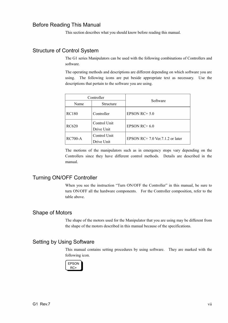
Structure of Control System The G1 series Manipulators can be used with the following combinations of Controllers and software.
The operating methods and descriptions are different depending on which software you are using. The following icons are put beside appropriate text as necessary. Use the descriptions that pertain to the software you are using.
Controller
Software Name Structure
RC180 Controller EPSON RC+ 5.0
RC620 Control Unit Drive Unit
EPSON RC+ 6.0
RC700-A Control Unit Drive Unit
EPSON RC+ 7.0 Ver.7.1.2 or later
The motions of the manipulators such as in emergency stops vary depending on the Controllers since they have different control methods. Details are described in the manual.
Turning ON/OFF Controller When you see the instruction “Turn ON/OFF the Controller” in this manual, be sure to turn ON/OFF all the hardware components. For the Controller composition, refer to the table above.
Shape of Motors The shape of the motors used for the Manipulator that you are using may be different from the shape of the motors described in this manual because of the specifications.
Setting by Using Software This manual contains setting procedures by using software. They are marked with the following icon.
EPSON RC+

viii G1 Rev.7

TABLE OF CONTENTS
G1 Rev.7 ix
Setup & Operation 1. Safety 3
1.1 Conventions ............................................................................................ 3 1.2 Design and Installation Safety ................................................................ 4 1.3 Operation Safety ..................................................................................... 5 1.4 Emergency Stop ..................................................................................... 7
1.4.1 RC180, RC620 ............................................................................. 7 1.4.2 RC700-A ....................................................................................... 9
1.5 Emergency Movement Without Drive Power ........................................ 11 1.6 Manipulator Labels ............................................................................... 12
2. Specifications 14 2.1 Features of G1 series Manipulators ..................................................... 14 2.2 Model Number and Model Differences ................................................... 14 2.3 Part Names and Outer Dimensions ...................................................... 15
2.3.1 4-axis spec .................................................................................. 15 2.3.2 3-axis spec .................................................................................. 19
2.4 Specifications ........................................................................................ 23 2.5 How to Set the Model ........................................................................... 25
3. Environments and Installation 26 3.1 Environmental Conditions ..................................................................... 26 3.2 Base Table ............................................................................................ 27 3.3 Mounting Dimensions ........................................................................... 29
3.3.1 4-axis spec .................................................................................. 30 3.3.2 3-axis spec .................................................................................. 31
3.4 Unpacking and Transportation .............................................................. 32 3.5 Installation Procedure ........................................................................... 33 3.6 Connecting the Cables ......................................................................... 34 3.7 User Wires and Pneumatic Tubes ........................................................ 35 3.8 Relocation and Storage ........................................................................ 36
4. Setting of End Effectors 37 4.1 Attaching an End Effector ..................................................................... 37 4.2 Weight and Inertia Settings .................................................................. 38
4.2.1 Weight Setting ........................................................................... 38 4.2.2 Inertia Setting ............................................................................ 40
4.3 Precautions for Auto Acceleration/Deceleration of Joint #3 ................. 43
5. Motion Range 44 5.1 Motion Range Setting by Pulse Range (for All Joints) ......................... 44 5.2 Motion Range Setting by Mechanical Stops ........................................ 46 5.3 Setting the Cartesian (Rectangular) Range in the XY Coordinate
System of the Manipulator (for Joints #1 and #2) .............................. 51 5.4 Standard Motion Range ........................................................................ 51

TABLE OF CONTENTS
x G1 Rev.7
Maintenance 1. Safety Maintenance 55
2. General Maintenance 56 2.1 Maintenance Inspection .......................................................................... 56
2.1.1 Schedule for Maintenance Inspection ....................................... 56 2.1.2 Inspection Point ......................................................................... 57
2.2 Overhaul .................................................................................................. 58 2.3 Greasing ................................................................................................ 59 2.4 Tightening Hexagon Socket Head Cap Bolts ........................................ 59 2.5 Matching Origins .................................................................................... 60 2.6 Layout of Maintenance Parts ................................................................ 60
3. Covers 62 3.1 Arm Top Cover ....................................................................................... 63 3.2 Connector Plate ..................................................................................... 64 3.3 Connector Sub Plate ............................................................................. 65 3.4 User Plate .............................................................................................. 65
4. Cable 66 4.1 Replacing Cable Unit ............................................................................. 67 4.2 Wiring Diagrams .................................................................................... 73
4.2.1 Signal Cable .............................................................................. 73 4.2.2 Power Cable .............................................................................. 74 4.2.3 User Cable ................................................................................. 75
4.3 Replacing M/C Cable ............................................................................ 76
5. Arm #1 78 5.1 Motor ...................................................................................................... 79 5.2 Reduction Gear Unit .............................................................................. 82
6. Arm #2 83 6.1 Motor ...................................................................................................... 84 6.2 Reduction Gear Unit .............................................................................. 86
7. Arm #3 90 7.1 Motor ...................................................................................................... 91 7.2 Timing Belt ............................................................................................. 95 7.3 Brake ..................................................................................................... 97

TABLE OF CONTENTS
G1 Rev.7 xi
8. Arm #4 98 8.1 Motor ..................................................................................................... 99 8.2 Timing Belt .......................................................................................... 103
9. Bellows 105 9.1 4-axis spec .......................................................................................... 106 9.2 3-axis spec .......................................................................................... 108
10. Ball Screw Spline Unit 110 10.1 Greasing the Ball Screw Spline Unit ................................................. 110
10.1.1 Standard-model ..................................................................... 111 10.1.2 Cleanroom-model .................................................................. 112
10.2 Replacing the Ball Screw Spline Unit ................................................ 113 10.2.1 4-axis spec ............................................................................... 114 10.2.2 3-axis spec ............................................................................... 117
11. Lithium Battery 120 11.1 Replacing the Battery Unit (Lithium Battery) .................................... 121 11.2 Replacing the Battery Board ............................................................. 122
12. LED Lamp 124
13. Calibration 125 13.1 About Calibration .............................................................................. 125 13.2 Calibration Procedure ....................................................................... 126 13.3 Accurate Calibration of Joint #2 ....................................................... 136 13.4 Calibration Procedure without using Calibration Wizard .................. 138
14. Maintenance Parts List 142 14.1 Common Parts .................................................................................. 142 14.2 Parts by Environment Model ............................................................ 143

TABLE OF CONTENTS
xii G1 Rev.7

Setup & Operation This volume contains information for setup and operation of the G1 series Manipulators. Please read this volume thoroughly before setting up and operating the Manipulators.

Setup & Operation 1. Safety
G1 Rev.7 3
1. Safety Installation and transportation of robots and robotic equipment shall be performed by qualified personnel and should conform to all national and local codes. Please read this manual and other related manuals before installing the robot system or before connecting cables. Keep this manual handy for easy access at all times.
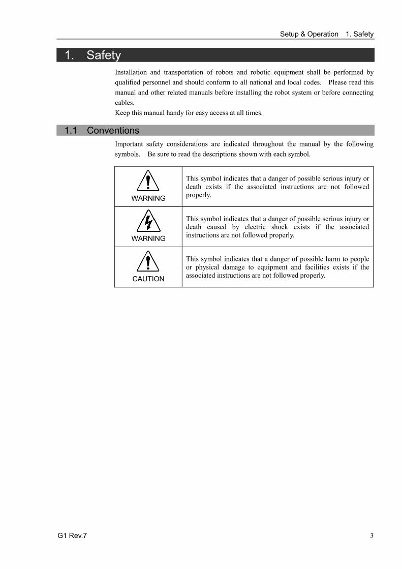
1.1 Conventions Important safety considerations are indicated throughout the manual by the following symbols. Be sure to read the descriptions shown with each symbol.
WARNING
This symbol indicates that a danger of possible serious injury or death exists if the associated instructions are not followed properly.
WARNING
This symbol indicates that a danger of possible serious injury or death caused by electric shock exists if the associated instructions are not followed properly.
CAUTION
This symbol indicates that a danger of possible harm to people or physical damage to equipment and facilities exists if the associated instructions are not followed properly.

Setup & Operation 1. Safety
4 G1 Rev.7
1.2 Design and Installation Safety Only trained personnel should design and install the robot system. Trained personnel are defined as those who have taken robot system training and maintenance training classes held by the manufacturer, dealer, or local representative company, or those who understand the manuals thoroughly and have the same knowledge and skill level as those who have completed the training courses. To ensure safety, a safeguard must be installed for the robot system. For details on the safeguard, refer to the Installation and Design Precautions in the Safety chapter of the EPSON RC+ User’s Guide. The following items are safety precautions for design personnel:
WARNING
■ Personnel who design and/or construct the robot system with this product must read the Safety chapter in the EPSON RC+ User’s Guide to understand the safety requirements before designing and/or constructing the robot system. Designing and/or constructing the robot system without understanding the safety requirements is extremely hazardous, may result in serious bodily injury and/or severe equipment damage to the robot system, and may cause serious safety problems.
■ The Manipulator and the Controller must be used within the environmental conditions described in their respective manuals. This product has been designed and manufactured strictly for use in a normal indoor environment. Using the product in an environment that exceeds the specified environmental conditions may not only shorten the life cycle of the product but may also cause serious safety problems.
■ The robot system must be used within the installation requirements described in the manuals. Using the robot system outside of the installation requirements may not only shorten the life cycle of the product but also cause serious safety problems.
Further precautions for installation are mentioned in the chapter Setup & Operation: 3. Environments and Installation. Please read this chapter carefully to understand safe installation procedures before installing the robots and robotic equipment.

Setup & Operation 1. Safety
G1 Rev.7 5
1.3 Operation Safety The following items are safety precautions for qualified Operator personnel:
WARNING
■ Please carefully read the Safety-related Requirements in the Safety chapter of the Safety and Installation manual before operating the robot system. Operating the robot system without understanding the safety requirements is extremely hazardous and may result in serious bodily injury and/or severe equipment damage to the robot system.
■ Do not enter the operating area of the Manipulator while the power to the robot system is turned ON. Entering the operating area with the power ON is extremely hazardous and may cause serious safety problems as the Manipulator may move even if it seems to be stopped.
■ Before operating the robot system, make sure that no one is inside the safeguarded area. The robot system can be operated in the mode for teaching even when someone is inside the safeguarded area. The motion of the Manipulator is always in restricted (low speeds and low power) status to secure the safety of an operator. However, operating the robot system while someone is inside the safeguarded area is extremely hazardous and may result in serious safety problems in case that the Manipulator moves unexpectedly.
■ Immediately press the Emergency Stop switch whenever the Manipulator moves abnormally while the robot system is operated.
WARNING
■ To shut off power to the robot system, pull out the power plug from the power source. Be sure to connect the AC power cable to a power receptacle. DO NOT connect it directly to a factory power source.
■ Before performing any replacement procedure, turn OFF the Controller and related equipment, and then pull out the power plug from the power source. Performing any replacement procedure with the power ON is extremely hazardous and may result in electric shock and/or malfunction of the robot system.
■ Do not insert or pull out the motor connectors while the power to the robot system is turned ON. Inserting or pulling out the motor connectors with the power ON is extremely hazardous and may result in serious bodily injury as the Manipulator may move abnormally, and also may result in electric shock and/or malfunction of the robot system.

Setup & Operation 1. Safety
6 G1 Rev.7
CAUTION
■ Whenever possible, only one person should operate the robot system. If it is necessary to operate the robot system with more than one person, ensure that all people involved communicate with each other as to what they are doing and take all necessary safety precautions.
■
Joint #1, #2, and #4: If the joints are operated repeatedly with the operating angle less than 5 degrees, they may get damaged early because the bearings are likely to cause oil film shortage in such situation. To prevent early breakdown, move the joints larger than 50 degrees for about five to ten times a day.
Joint #3: If the up-and-down motion of the hand is less than 10 mm, move the joint a half of the maximum stroke for five to ten times a day.

Setup & Operation 1. Safety
G1 Rev.7 7
1.4 Emergency Stop Emergency stop motions of the Manipulators vary due to difference of control methods of the Controllers. See the section for your Controller model.
1.4.1 RC180, RC620 If the Manipulator moves abnormally during operation, immediately press the Emergency Stop switch. Stops the power supply to the motor, and the arm stops in the shortest distance with the dynamic brake and mechanical brake.
However, avoid pressing the Emergency Stop switch unnecessarily while the Manipulator is running normally. Otherwise, the Manipulator may hit the peripheral equipment since the operating trajectory while the robot system stops is different from that in normal operation. It may also result in short life of the reduction gear unit due to the shock or the electromagnetic brake due to the worn friction plate. To place the system in emergency mode during normal operation, press the Emergency Stop switch when the Manipulator is not moving. Refer to the Controller manual for instructions on how to wire the Emergency Stop switch circuit. Do not press the Emergency Stop switch unnecessarily while the Manipulator is operating. Pressing the switch during the operation makes the brakes work. This will shorten the life of the brakes due to the worn friction plates.
Normal brake life cycle: About 2 years (when the brakes are used 100 times/day) Do not turn OFF the Controller while the Manipulator is operating. If you attempt to stop the Manipulator in emergency situations such as “Safeguard Open”, make sure to stop the Manipulator using the Emergency Stop switch of the Controller. If the Manipulator is stopped by turning OFF the Controller while it is operating, following problems may occur. Reduction of the life and damage of the reduction gear unit Position gap at the joints In addition, if the Controller was forced to be turned OFF by blackouts and the like while the Manipulator is operating, make sure to check the following points after power restoration. Whether or not the reduction gear is damaged Whether or not the joints are in their proper positions If there is a position gap, perform calibration by referring to the Maintenance 13. Calibration in this manual. Before using the Emergency Stop switch, be aware of the followings. - The Emergency Stop (E-STOP) switch should be used to stop the Manipulator only
in case of emergencies. - To stop the Manipulator operating the program except in emergency, use Pause (halt)
or STOP (program stop) commands. Pause and STOP commands do not turn OFF the motors. Therefore, the brake does not function.
- For the Safeguard system, do not use the circuit for E-STOP.
Setup & Operation 1. Safety
8 G1 Rev.7
For details of the Safeguard system, refer to the following manuals. EPSON RC+ User’s Guide 2. Safety - Installation and Design Precautions - Safeguard System Safety and Installation 2.6 Connection to EMERGENCY Connector
To check brake problems, refer to the following manuals. Manipulator Manual Maintenance 2.2.2 Inspection While the Power is ON
(Manipulator is operating) Safety and Installation 5.2 Inspection Point - Inspection While the
Power is ON (Manipulator is operating) Free running distance in emergency The operating Manipulator cannot stop immediately after the Emergency Stop switch is pressed. The free running time/angle/distance of the Manipulator are shown below. However, remember that the values vary depending on following conditions.
Weight of the end effector Weight of work piece Operating pose Weight Speed Accel etc.
Conditions for measurement
Accel setting 100 Speed setting 100 Load [kg] 1 Weight setting 1
Joint #1
Stop point
Point where the emergency stop signal is input
Target point
Start point of operation
Joint #2
Controller RC180, RC620
Manipulator G1-171*/ G1-171*Z G1-221*/ G1-221*Z
Free running time
Joint #1 + Joint #2 [sec.] 0.4
Joint #3 [sec.] 0.3
Free running angle
Joint #1 [deg.] 40 50
Joint #2 [deg.] 40 45
Joint #1 + Joint #2 [deg.] 80 95
Free running distance
Joint #3 [mm] 50

Setup & Operation 1. Safety
G1 Rev.7 9
1.4.2 RC700-A
If the Manipulator moves abnormally during operation, immediately press the Emergency Stop switch. Pressing the Emergency Stop switch immediately changes the manipulator to the low-speed motion and stops it at the maximum deceleration speed.
However, avoid pressing the Emergency Stop switch unnecessarily while the Manipulator is running normally. Pressing the Emergency Stop switch locks the brake and it may cause wear on the friction plate of the brake, resulting in the short life of the brake.
Normal brake life cycle: About 2 years (when the brakes are used 100 times/day) To place the system in emergency mode during normal operation, press the Emergency Stop switch when the Manipulator is not moving. Refer to the Controller manual for instructions on how to wire the Emergency Stop switch circuit. Do not turn OFF the Controller while the Manipulator is operating. If you attempt to stop the Manipulator in emergency situations such as “Safeguard Open”, make sure to stop the Manipulator using the Emergency Stop switch of the Controller. If the Manipulator is stopped by turning OFF the Controller while it is operating, following problems may occur. Reduction of the life and damage of the reduction gear unit Position gap at the joints In addition, if the Controller was forced to be turned OFF by blackouts and the like while the Manipulator is operating, make sure to check the following points after power restoration. Whether or not the reduction gear is damaged Whether or not the joints are in their proper positions If there is a position gap, perform calibration by referring to the Maintenance 13. Calibration in this manual. Before using the Emergency Stop switch, be aware of the followings. - The Emergency Stop (E-STOP) switch should be used to stop the Manipulator only
in case of emergencies. - To stop the Manipulator operating the program except in emergency, use Pause (halt)
or STOP (program stop) commands. Pause and STOP commands do not turn OFF the motors. Therefore, the brake does not function.
- For the Safeguard system, do not use the circuit for E-STOP.
For details of the Safeguard system, refer to the following manuals. EPSON RC+ User’s Guide 2. Safety - Installation and Design Precautions - Safeguard System Safety and Installation 2.6 Connection to EMERGENCY Connector

Setup & Operation 1. Safety
10 G1 Rev.7
To check brake problems, refer to the following manuals. Manipulator Manual Maintenance 2.2.2 Inspection While the Power is ON
(Manipulator is operating) Safety and Installation 5.2 Inspection Point - Inspection While the
Power is ON (Manipulator is operating) Free running distance in emergency The operating Manipulator cannot stop immediately after the Emergency Stop switch is pressed. The free running time/angle/distance of the Manipulator are shown below. However, remember that the values vary depending on following conditions.
Weight of the end effector Weight of work piece Operating pose Weight Speed Accel etc.
Conditions for measurement
Accel setting 100 Speed setting 100 Load [kg] 1 Weight setting 1
Joint #1
Stop point
Point where the emergency stop signal is input
Target point
Start point of operation
Joint #2
Controller RC700-A
Manipulator G1-171*, G1-171*Z G1-221*, G1-221*Z
Free running time Joint #1 + Joint #2 [sec.] 0.17 0.18
Joint #3 [sec.] 0.13
Free running angle
Joint #1 [deg.] 22 28
Joint #2 [deg.] 19 20
Joint #1 + Joint #2 [deg.] 41 48
Free running distance Joint #3 [mm] 48

Setup & Operation 1. Safety
G1 Rev.7 11
1.5 Emergency Movement Without Drive Power When the system is placed in emergency mode, push the arm or joint of the Manipulator by hand as shown below:
Arm #1 ............. Push the arm by hand.
Arm #2 ............. Push the arm by hand.
Joint #3 ............ The joint cannot be moved up/down by hand until the electromagnetic brake applied to the joint has been released. Move the joint up/down while pressing the brake release switch.
Joint #4 ........... Rotate the shaft by hand. Joint #3 brake release button
Joint #1 (rotating)
Joint #2 (rotating)
Joint #3 (up/down)
Joint #4 (rotating)
Arm #1
Arm #2
Base
Shaft
When the brake release switch is pressed in emergency mode, the brake for Joint #3 is released. Be careful of the shaft while the brake release switch is pressed because the shaft may be lowered by the weight of an end effector.
NOTE

Setup & Operation 1. Safety
12 G1 Rev.7
1.6 Manipulator Labels The following labels are attached near the locations of the Manipulator where specific dangers exist. Be sure to comply with descriptions and warnings on the labels to operate and maintain the Manipulator safely. Do not tear, damage, or remove the labels. Use meticulous care when handling those parts or units to which the following labels are attached as well as the nearby areas:
Location Labels NOTE
A
Before loosening the base mounting screws, hold the arm and secure it tightly with a band to prevent hands or fingers from being caught in the Manipulator.
B
Be careful to avoid collision.
C
Hazardous voltage exists while the Manipulator is ON. To avoid electric shock, do not touch any internal electric parts.
D
(Only UL model)
Only authorized personnel should perform sling work and operate a crane and a forklift. When these operations are performed by unauthorized personnel, it is extremely hazardous and may result in serious bodily injury and/or severe equipment damage to the robot system.
E
Be careful of the hand falling while the brake release switch is being pressed.
F
G

Setup & Operation 1. Safety
G1 Rev.7 13
Location of Labels
A C
B D
E
F
G

Setup & Operation 2. Specifications
14 G1 Rev.7
2. Specifications
2.1 Features of G1 series Manipulators
The G1 series Manipulators are high-performance manipulators intended to space saving, achieve high speed, high DUTY, and high rigidity.
The features of the G1 series Manipulators are as follows: High Accuracy & High Speed & High Rigidity
Repeating positioning accuracy is ± 0.005 mm Optimum for precision assembling production line Cycle time under 0.3 seconds (with 175 mm arm) * When moving 100 mm in horizontally, 25 mm in vertically with load 0.5 kg Small body yet powerful (Press force: 50N)
Space Saving
Achieves the motion area equivalent to the upper class robot with 225 mm arm Easy-to-Use
You can easily operate the Light & Compact body 3-Axis Spec
Optimum for screw driving and pressing work using the hand offset
2.2 Model Number G1-17 1 S Z-UL
UL specification
UL : UL compliant □ : Non UL compliant
Environment
S : Standard C : Cleanroom &ESD
Joint #3 stroke
1 : 100 mm
For details of the specifications, refer to Setup & Operation: 2.4 Specifications.
Axis □ : 4-axis spec Z : 3-axis spec
Arm length 17 : 175 mm 22 : 225 mm

Setup & Operation 2. Specifications
G1 Rev.7 15
2.3 Part Names and Outer Dimensions
2.3.1 4-axis spec Part Names : Standard-model (G1-***S)
Signal cable
Power cable
Fitting (black or blue)* for ø4 mm pneumatic tube
User connector (9-pin D-sub connector)
LED
MT label (only for special order)
Face plate (Manipulator serial No.)
CE label
Joint #3 Brake release switch
Base
Shaft
User connector (15-pin D-sub connector)
Fitting (black or blue)* for ø6 mm pneumatic tube
Fittings (white) for ø6 mm pneumatic tube
UR label
Cable
User connector (9-pin D-sub connector)
User connector (15-pin D-sub connector)
Fittings (white) for ø6 mm pneumatic tube
Fitting (black or blue)* for ø6 mm pneumatic tube Fitting (black or blue)*
for ø4 mm pneumatic tube
* Color differs depending on the shipment time - The brake release switch affects only Joint #3. When the brake release switch is
pressed in emergency mode, the brake for Joint #3 is released simultaneously. - When the LED lamp is lighting or the controller power is on, the current is being
applied to the manipulator. Performing any work with the power ON is extremely hazardous and it may result in electric shock and/or improper function of the robot system. Make sure to turn OFF the controller power before the maintenance work.
NOTE

Setup & Operation 2. Specifications
16 G1 Rev.7
Part Dimension : Standard-model (G1-***S)
1mm flat cut shaft diameter
90 or more Space for cables
mechanical stop diameter
not penetrable
G1-171S G1-221S a 75 125 b Max.515 Max.545
Reference through hole (View from the bottom of the base)
Detail of “A” (Calibration point position of
Joints #3 and #4)
(*) indicates the stroke margin by mechanical stop.
Setup & Operation 2. Specifications
G1 Rev.7 17
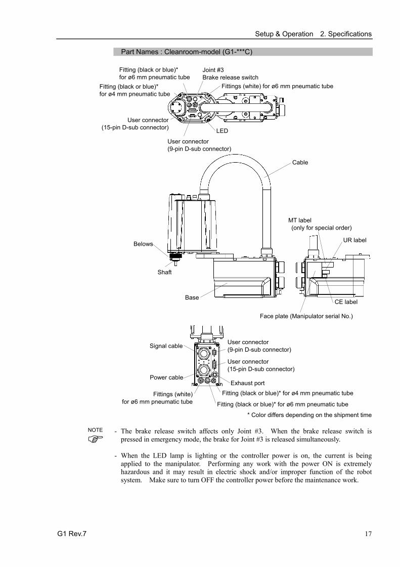
Part Names : Cleanroom-model (G1-***C)
Belows
Exhaust port
Signal cable
Power cable
Fitting (black or blue)* for ø4 mm pneumatic tube
User connector (9-pin D-sub connector)
LED
MT label (only for special order)
Face plate (Manipulator serial No.)
CE label
Joint #3 Brake release switch
Base
Shaft
User connector (15-pin D-sub connector)
Fitting (black or blue)* for ø6 mm pneumatic tube
Fittings (white) for ø6 mm pneumatic tube
UR label
Cable
User connector (9-pin D-sub connector)
User connector (15-pin D-sub connector)
Fittings (white) for ø6 mm pneumatic tube
Fitting (black or blue)* for ø6 mm pneumatic tube Fitting (black or blue)*
for ø4 mm pneumatic tube
* Color differs depending on the shipment time - The brake release switch affects only Joint #3. When the brake release switch is
pressed in emergency mode, the brake for Joint #3 is released simultaneously. - When the LED lamp is lighting or the controller power is on, the current is being
applied to the manipulator. Performing any work with the power ON is extremely hazardous and it may result in electric shock and/or improper function of the robot system. Make sure to turn OFF the controller power before the maintenance work.
NOTE

Setup & Operation 2. Specifications
18 G1 Rev.7
Part Dimension : Cleanroom-model (G1-***C)
G1-171C G1-221C a 75 125 b Max.515 Max.545
1mm flat cut
shaft diameter
90 or more Space for cables
mechanical stop diameter
not penetrable
Reference through hole (View from the bottom of the base)
Detail of “A” (Calibration point position of
Joints #3 and #4)
(*) indicates the stroke margin by mechanical stop.

Setup & Operation 2. Specifications
G1 Rev.7 19
2.3.2 3-axis spec Part Names : Standard-model (G1-***Z)
Signal cable
Power cable
Fitting (black or blue)* for ø4 mm pneumatic tube
User connector (9-pin D-sub connector)
LED
MT label (only for special order)
Face plate (Manipulator serial No.)
CE label
Joint #3 Brake release switch
Base
Shaft
User connector (15-pin D-sub connector)
Fitting (black or blue)* for ø6 mm pneumatic tube
Fittings (white) for ø6 mm pneumatic tube
UR label
Cable
User connector (9-pin D-sub connector)
User connector (15-pin D-sub connector)
Fittings (white) for ø6 mm pneumatic tube
Fitting (black or blue)* for ø6 mm pneumatic tube Fitting (black or blue)*
for ø4 mm pneumatic tube
* Color differs depending on the shipment time
- The brake release switch affects only Joint #3. When the brake release switch is
pressed in emergency mode, the brake for Joint #3 is released simultaneously. - When the LED lamp is lighting or the controller power is on, the current is being
applied to the manipulator. Performing any work with the power ON is extremely hazardous and it may result in electric shock and/or improper function of the robot system. Make sure to turn OFF the controller power before the maintenance work.
NOTE

Setup & Operation 2. Specifications
20 G1 Rev.7
Part Dimension : Standard-model (G1-***Z)
G1-171Z G1-221Z a 75 125 b Max.515 Max.545
1mm flat cut
shaft diameter
90 or more Space for cables
not penetrable
Reference through hole (View from the bottom of the base)
Detail of “A” (Calibration point position of
Joints #3 and #4)
(*) indicates the stroke margin by mechanical stop.
2-M3 Through hole

Setup & Operation 2. Specifications
G1 Rev.7 21
Part Names : Cleanroom-model (G1-***CZ)
Signal cable
Power cable
Fitting (black or blue)* for ø4 mm pneumatic tube
User connector (9-pin D-sub connector)
LED
MT label (only for special order)
Face plate (Manipulator serial No.)
CE label
Joint #3 Brake release switch
Base
Shaft
User connector (15-pin D-sub connector)
Fitting (black or blue)* for ø6 mm pneumatic tube
Fittings (white) for ø6 mm pneumatic tube
UR label
Cable
User connector (9-pin D-sub connector)
User connector (15-pin D-sub connector)
Fittings (white) for ø6 mm pneumatic tube
Fitting (black or blue)* for ø6 mm pneumatic tube Fitting (black or blue)*
for ø4 mm pneumatic tube
Belows
Exhaust port
Belows
* Color differs depending on the shipment time
- The brake release switch affects only Joint #3. When the brake release switch is
pressed in emergency mode, the brake for Joint #3 is released simultaneously. - When the LED lamp is lighting or the controller power is on, the current is being
applied to the manipulator. Performing any work with the power ON is extremely hazardous and it may result in electric shock and/or improper function of the robot system. Make sure to turn OFF the controller power before the maintenance work.
NOTE

Setup & Operation 2. Specifications
22 G1 Rev.7
Part Dimension : Cleanroom-model (G1-***CZ)
G1-171CZ G1-221CZ a 75 125 b Max.515 Max.545
1mm flat cut shaft diameter
90 or more Space for cables
not penetrable
Reference through hole (View from the bottom of the base)
Detail of “A” (Calibration point position of
Joints #3 and #4)
(*) indicates the stroke margin by mechanical stop.

Setup & Operation 2. Specifications
G1 Rev.7 23
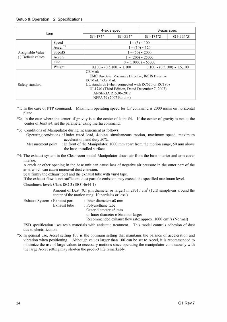
2.4 Specifications
Item 4-axis spec 3-axis spec
G1-171* G1-221* G1-171* G1-221* Mounting type Table Top
Arm length #1, #2
Arm #1, #2 175 mm 225 mm 175 mm 225 mm Arm #1 75 mm 125 mm 75 mm 125 mm Arm #2 100 mm 100 mm
Weight (cables not included) 8 kg 8 kg Driving method All joints AC servo motor
Max. operating speed *1
Joints #1, #2 2630 mm/s 3000 mm/s 2630 mm/s 3000 mm/s Joints #3 (Z) 1200 mm/s 1200 mm/s Joints #4 (U) 3000 deg/s -
Repeatability Joints #1, #2 ± 0.005 mm ± 0.008 mm ± 0.005 mm ± 0.008 mm Joints #3 (Z) ± 0.01 mm ± 0.01 mm Joints #4 (U) ± 0.01 deg. -
Max. motion range
Joints #1 ± 125 deg. ± 125 deg Joints #2 (Cleanroom model)
± 140 deg. (± 140 deg.)
± 152 deg. (±149 deg.)
± 135 deg. (±123 deg.)
± 135 deg. (±132 deg.)
Z stroke (Cleanroom model) ± 100 (80) mm ± 100 (80) mm
Joints #4 ± 360 deg -
Max. pulse range (pulse)
Joints #1 − 1019449 ∼ 6262329 pulse Joints #2 (Cleanroom model)
± 2548623 (± 2548623)
± 2767076 (± 2712463)
± 2457600 (± 2239147)
± 2457600 (± 2402987)
Joints #3 (Cleanroom model)
− 1092267 ∼ 0 (-873813 ∼ 0)
Joints #4 − 393216 ∼ 393216
Resolution
Joints #1 3.43322E-05 deg/pulse Joints #2 5.49316E-05 deg/pulse Joints #3 9.15527E-05 mm/pulse Joints #4 9.15527E-04 deg/pulse
Motor power consumption All joints: 50 W
Payload Rated 0.5 kg 0.5 kg Maximum 1 kg 1.5 kg
Joint #4 allowable moment of inertia *2
Rated 0.0003 kg·m2 - Maximum 0.004 kg·m2 -
Shaft diameter ø 8 mm Mounting hole 125×88 (4-M6) Joint #3 down force 50 N Installed wire for customer use 24 pin (9 + 15)
Installed pneumatic tube for customer use 1 pneumatic tube (ø 4 mm): 0.59 Mpa (6 kgf/cm2 : 86 psi) 2 pneumatic tubes (ø 6 mm): 0.59 Mpa (6 kgf/cm2 : 86 psi)
Environmental requirements
Ambient temperature 5 to 40 degree C (with minimum temperature variation) Ambient relative humidity 10 to 80 % RH (no condensation) Vibration level 4.9 m/s2 (0.5G) or less
Noise level *3 65dB Installation environment Standard / Cleanroom + ESD (ISO Class 3) *4 Applicable Controller RC180, RC620, RC700-A
Setup & Operation 2. Specifications
24 G1 Rev.7
Item 4-axis spec 3-axis spec
G1-171* G1-221* G1-171*Z G1-221*Z
Assignable Value ( ) Default values
Speed 1 ∼ (5) ∼ 100 Accel *5 1 ∼ (10) ∼ 120 SpeedS 1 ∼ (50) ∼ 2000 AccelS 1 ∼ (200) ∼ 25000 Fine 0 ∼ (10000) ∼ 65000 Weight 0,100 ∼ (0.5,100) ∼ 1,100 0,100 ∼ (0.5,100) ∼ 1.5,100
Safety standard
CE Mark EMC Directive, Machinery Directive, RoHS Directive
KC Mark / KCs Mark UL standards (when connected with RC620 or RC180)
UL1740 (Third Edition, Dated December 7, 2007) ANSI/RIA R15.06-2012 NFPA 79 (2007 Edition)
*1: In the case of PTP command. Maximum operating speed for CP command is 2000 mm/s on horizontal
plane. *2: In the case where the center of gravity is at the center of Joint #4. If the center of gravity is not at the
center of Joint #4, set the parameter using Inertia command.
*3: Conditions of Manipulator during measurement as follows: Operating conditions : Under rated load, 4-joints simultaneous motion, maximum speed, maximum
acceleration, and duty 50%. Measurement point : In front of the Manipulator, 1000 mm apart from the motion range, 50 mm above
the base-installed surface.
*4: The exhaust system in the Cleanroom-model Manipulator draws air from the base interior and arm cover interior. A crack or other opening in the base unit can cause loss of negative air pressure in the outer part of the arm, which can cause increased dust emission. Seal firmly the exhaust port and the exhaust tube with vinyl tape. If the exhaust flow is not sufficient, dust particle emission may exceed the specified maximum level. Cleanliness level : Class ISO 3 (ISO14644-1)
Amount of Dust (0.1 µm diameter or larger) in 28317 cm3 (1cft) sample-air around the center of the motion rang: 10 particles or less.)
Exhaust System : Exhaust port : Inner diameter: ø8 mm Exhaust tube : Polyurethane tube Outer diameter ø8 mm or Inner diameter ø16mm or larger Recommended exhaust flow rate: approx. 1000 cm3/s (Normal)
ESD specification uses resin materials with antistatic treatment. This model controls adhesion of dust due to electrification.
*5: In general use, Accel setting 100 is the optimum setting that maintains the balance of acceleration and vibration when positioning. Although values larger than 100 can be set to Accel, it is recommended to minimize the use of large values to necessary motions since operating the manipulator continuously with the large Accel setting may shorten the product life remarkably.

Setup & Operation 2. Specifications
G1 Rev.7 25
2.5 How to Set the Model The Manipulator model for your system has been set before shipment from the factory. It is normally not required to change the model when you receive your system.
CAUTION
■ When you need to change the setting of the Manipulator model, be sure to set the Manipulator model properly. Improper setting of the Manipulator model may result in abnormal or no operation of the Manipulator and/or cause safety problems.
If an MT label is attached to the rear of a Manipulator, the Manipulator has custom specifications. The custom specifications may require a different configuration procedure; check the custom specifications number described on the MT label and contact us when necessary. The Manipulator model can be set from software. Refer to the chapter Robot Configuration in the EPSON RC+ User’s Guide.
NOTE

Setup & Operation 3. Environments and Installation
26 G1 Rev.7
3. Environments and Installation
3.1 Environmental Conditions
A suitable environment is necessary for the robot system to function properly and safely. Be sure to install the robot system in an environment that meets the following conditions:
Item Conditions
Ambient temperature *1 5 to 40°C (with minimum temperature variation)
Ambient relative humidity 10 to 80% (no condensation)
First transient burst noise 2 kV or less (Power supply wire) 1 kV or les (Signal wire)
Electrostatic noise 4 kV or less
Environment · Install indoors. · Keep away from direct sunlight. · Keep away from dust, oily smoke, salinity, metal
powder or other contaminants. · Keep away from flammable or corrosive solvents
and gases. · Keep away from water and oil. · Keep away from shocks or vibrations. · Keep away from sources of electric noise.
Manipulators are not suitable for operation in harsh environments such as painting areas, etc. When using Manipulators in inadequate environments that do not meet the above conditions, please contact us.
*1 The ambient temperature conditions are for the Manipulators only. For the Controller the Manipulators are connected to, refer to the Controller manual.
NOTE

Setup & Operation 3. Environments and Installation
G1 Rev.7 27
3.2 Base Table A base table for anchoring the Manipulator is not supplied. Please make or obtain the base table for your Manipulator. The shape and size of the base table differs depending on the use of the robot system. For your reference, we list some Manipulator table requirements here. The base table must not only be able to bear the weight of the Manipulator but also be able to withstand the dynamic movement of the Manipulator when the Manipulator operates at maximum acceleration. Ensure that there is enough strength on the base table by attaching reinforcing materials such as crossbeams. The torque and reaction force produced by the movement of the Manipulator are as follows:
Max. Reaction torque on the horizontal plate : 100 Nm
Max. Horizontal reaction force : 200 N
Max. Vertical reaction force : 300 N
The threaded holes required for mounting the Manipulator base are M6. Use mounting bolts with specifications conforming to ISO898-1 property class: 10.9 or 12.9. For dimensions, refer to Setup & Operation: 3.3 Mounting Dimensions.
The plate for the Manipulator mounting face should be 15 mm thick or more and made of steel to reduce vibration. The surface roughness of the steel plate should be 25 μm or less.
The table must be secured on the floor or wall to prevent it from moving.
The Manipulator must be installed horizontally.
When using a leveler to adjust the height of the base table, use a screw with M8 diameter or more.

Setup & Operation 3. Environments and Installation
28 G1 Rev.7
If you are passing cables through the holes on the base table, see the figures below. [unit : mm]
M/C Cables
Power Cable Connector
Signal Cable Connector
47
26
53 18
RC180, RC620
54
35
49 11
82
44
Power Cable Connector (Straight)
Signal Cable Connector
83 76
Power Cable Connector (L-shaped)
35
RC700-A
Do not remove the M/C cables from the Manipulator.
For environmental conditions regarding space when placing the Controller on the base table, refer to the Controller manual.
WARNING
■ To ensure safety, a safeguard must be installed for the robot system. For details on the safeguard, refer to the EPSON RC+ User’s Guide.
NOTE

Setup & Operation 3. Environments and Installation
G1 Rev.7 29
3.3 Mounting Dimensions The maximum space described in figures shows that the radius of the end effector is 30 mm or less. If the radius of the end effector exceeds 30 mm, define the radius as the distance to the outer edge of maximum space. If a camera or electromagnetic valve extends outside of the arm, set the maximum range including the space that they may reach.
g Length of Arm #1 (mm)
h-g Length of Arm #2 (mm) m Stroke of Joint #3 (mm) f Motion range a Motion range of Joint #1 (degree) c Motion range of Joint #2 (degree) e Mechanical stop area b Joint #1 angle to hit mechanical stop (degree) d Joint #2 angle to hit mechanical stop (degree) n Joint #3 range to hit lower mechanical stop (mm) p Joint #3 range to hit upper mechanical stop (mm) j Range from center of axis to back end (mm) k Range from center of axis to back end after moved to mechanical stop (mm) q Joint #2 motion range + angle to hit mechanical stop (degree)
Be sure to allow for the following extra spaces in addition to the space required for mounting the Manipulator, Controller, and peripheral equipment.
space for teaching
space for maintenance and inspection (Ensure a space to open the rear side cover and the maintenance cover for maintenance.)

Setup & Operation 3. Environments and Installation
30 G1 Rev.7
3.3.1 4-axis spec Standard-model (G1-***S)
Center of Joint#3
Maximum space
Motion range
Area limited by mechanical stop
Base mounting face (unit: mm, ° = degree)
a b c d e f g h j k m n p q G1-171S
125° 3° 140° 3° 60.4 64.3 75 175 143 146.1
100 6 2.5 143°
G1-221S 152° 4° 52.8 59.6 125 225 171.6 176.9 154°
Cleanroom-model (G1-***C)
Center of Joint#3
Maximum space Motion range
Area limited by mechanical stop
Base mounting face (unit: mm, ° = degree)
a b c d e f g h j k m n p q G1-171C
125° 3° 140° 3° 62.6 64.3 75 175 143 146.1
80 3 2.5 143°
G1-221C 149° 5° 56.2 64.8 125 225 171.6 176.9 154°

Setup & Operation 3. Environments and Installation
G1 Rev.7 31
3.3.2 3-axis spec Standard-model (G1-***SZ)
Center of Joint#3
Maximum space Motion range
Area limited by mechanical stop
Base mounting face (unit: mm, ° = degree)
a b c d e f g h j k m n p q G1-171SZ
125° 3° 135° 1.3° 69.2 70.9 75 175 143 146.1
100 6 2.5 136.3°
G1-221SZ 4° 82.2 89.2 125 225 171.6 176.9 139°
Cleanroom-model (G1-***CZ)
Center of Joint#3
Maximum space Motion range
Area limited by mechanical stop
Base mounting face (uinit mm, ° = degree)
a b c d e f g h j k m n p q G1-171CZ
125° 3° 123° 3° 82.5 86.4 75 175 143 146.1
80 3 2.5 126°
G1-221CZ 132° 7° 82.2 94.4 125 225 171.6 176.9 139°

Setup & Operation 3. Environments and Installation
32 G1 Rev.7
3.4 Unpacking and Transportation
THE INSTALLATION SHALL BE PREFORMED BY QUALIFIED INSTALLATION PERSONNEL AND SHOULD CONFORM TO ALL NATIONAL AND LOCAL CODES.
WARNING
■ Only authorized personnel should perform sling work and operate a crane and a forklift. When these operations are performed by unauthorized personnel, it is extremely hazardous and may result in serious bodily injury and/or severe equipment damage to the robot system.
CAUTION
■ Using a cart or similar equipment, transport the Manipulator in the same manner as it was delivered.
■ To carry the Manipulator, secure the Manipulator to the delivery equipment or hold the areas indicated in gray in the figure (bottom of Arm #1 and bottom of the base) by hand. Never hold the duct to carry the Manipulator. There are the possibility such as the damage of cable and duct.
G1-171S approx. 8 kg :18 lb.
Duct DO NOT hold here for carrying
Hold here for carrying
■ Be careful not to get hands or fingers caught when holding the bottom of the base
by hand. ■ Stabilize the Manipulator with your hands when hoisting it. ■ When transporting the Manipulator for a long distance, secure it to the delivery
equipment directly so that the Manipulator never falls. If necessary, pack the Manipulator in the same style as it was delivered.

Setup & Operation 3. Environments and Installation
G1 Rev.7 33
3.5 Installation
CAUTION
■ Be careful not to get hands, fingers, or feet caught and/or have equipment damaged by a fall of the Manipulator when installing or transporting it. Manipulator weight: approx. 8 kg: 18 lb.
■ The robot system must be installed to avoid interference with buildings, structures, utilities, other machines and equipment that may create a trapping hazard or pinch points.
■ Do not allow unnecessary strain on the arm.
The unnecessary strain on the arm may result in damage to the bearing and/or the arm.
Max. press force: 50N (Arm tip)
Secure the base to the base table. bolt (4-M6×25) + spring washer + flat washer
Use bolts with specifications conforming to ISO898-1 Property Class: 6.9.
Tightening torque: 13 N·m (133 kgf·cm)
NOTE

Setup & Operation 3. Environments and Installation
34 G1 Rev.7
3.6 Connecting the Cables
WARNING
■ To shut off power to the robot system, pull out the power plug from the power source. Be sure to connect the AC power cable to a power receptacle. DO NOT connect it directly to a factory power source.
■ Before performing any replacement procedure, turn OFF the Controller and related equipment, and then pull out the power plug from the power source. Performing any replacement procedure with the power ON is extremely hazardous and may result in electric shock and/or malfunction of the robot system.
■ Be sure to connect the cables properly. Do not allow unnecessary strain on the cables. (Do not put heavy objects on the cables. Do not bend or pull the cables forcibly.) The unnecessary strain on the cables may result in damage to the cables, disconnection, and/or contact failure. Damaged cables, disconnection, or contact failure is extremely hazardous and may result in electric shock and/or improper function of the robot system.
■ Grounding the manipulator is done by connecting with the controller. Ensure that the controller is grounded and the cables are correctly connected. If the ground wire is improperly connected to ground, it may result in the fire or electric shock.
CAUTION
■ When connecting the Manipulator to the Controller, make sure that the serial numbers on each equipment match. Improper connection between the Manipulator and Controller may not only cause improper function of the robot system but also serious safety problems. The connection method varies with the Controller used. For details on the connection, refer to the Controller manual. If the G series Manipulator is connected to the Controller for the 6-axis robot, it may result in malfunction of the Manipulator.
Setup & Operation 3. Environments and Installation
G1 Rev.7 35
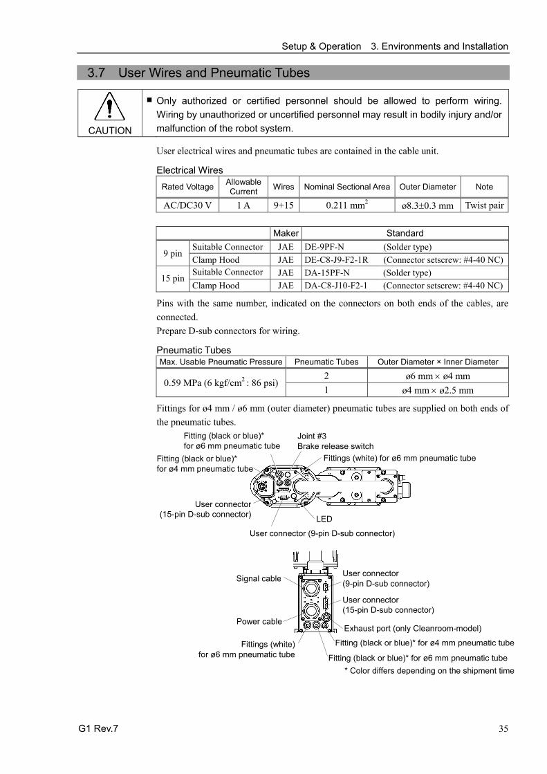
3.7 User Wires and Pneumatic Tubes
CAUTION
■ Only authorized or certified personnel should be allowed to perform wiring. Wiring by unauthorized or uncertified personnel may result in bodily injury and/or malfunction of the robot system.
User electrical wires and pneumatic tubes are contained in the cable unit.
Electrical Wires Rated Voltage Allowable
Current Wires Nominal Sectional Area Outer Diameter Note
AC/DC30 V 1 A 9+15 0.211 mm2 ø8.3±0.3 mm Twist pair
Maker Standard
9 pin Suitable Connector JAE DE-9PF-N (Solder type) Clamp Hood JAE DE-C8-J9-F2-1R (Connector setscrew: #4-40 NC)
15 pin Suitable Connector JAE DA-15PF-N (Solder type) Clamp Hood JAE DA-C8-J10-F2-1 (Connector setscrew: #4-40 NC)
Pins with the same number, indicated on the connectors on both ends of the cables, are connected. Prepare D-sub connectors for wiring.
Pneumatic Tubes Max. Usable Pneumatic Pressure Pneumatic Tubes Outer Diameter × Inner Diameter
0.59 MPa (6 kgf/cm2 : 86 psi) 2 ø6 mm × ø4 mm 1 ø4 mm × ø2.5 mm
Fittings for ø4 mm / ø6 mm (outer diameter) pneumatic tubes are supplied on both ends of the pneumatic tubes.
User connector (9-pin D-sub connector)
LED
Joint #3 Brake release switch
User connector (15-pin D-sub connector)
Fittings (white) for ø6 mm pneumatic tube
Fitting (black or blue)* for ø6 mm pneumatic tube Fitting (black or blue)*
for ø4 mm pneumatic tube
Exhaust port (only Cleanroom-model)
Signal cable
Power cable
Fitting (black or blue)* for ø4 mm pneumatic tube
User connector (15-pin D-sub connector)
Fitting (black or blue)* for ø6 mm pneumatic tube
Fittings (white) for ø6 mm pneumatic tube
User connector (9-pin D-sub connector)
* Color differs depending on the shipment time
Setup & Operation 3. Environments and Installation
36 G1 Rev.7
3.8 Relocation and Storage
Observe the following when relocating, storing, and transporting the Manipulators.
THE INSTALLATION SHALL BE PREFORMED BY QUALIFIED INSTALLATION PERSONNEL AND SHOULD CONFORM TO ALL NATIONAL AND LOCAL CODES.
WARNING
■ Only authorized personnel should perform sling work and operate a crane and a forklift. When these operations are performed by unauthorized personnel, it is extremely hazardous and may result in serious bodily injury and/or severe equipment damage to the robot system.
CAUTION
■ Before relocating the Manipulator, fold the arm and secure it tightly with a wire tie to prevent hands or fingers from being caught in the Manipulator.
■ When removing the anchor bolts, support the Manipulator to prevent falling. Removing the anchor bolts without support may result in a fall of the Manipulator, and then get hands, fingers, or feet caught.
■ To carry the Manipulator, secure the Manipulator to the delivery equipment or hold the bottom of Arm #1, the bottom of the main cable fitting, and the bottom of the base by hand. When holding the bottom of the base by hand, be very careful not to get hands or fingers caught. Do not hold the duct joint on the back of the base.
■ Stabilize the Manipulator with your hands when hoisting it. Unstable hoisting is extremely hazardous and may result in fall of the Manipulator.
When transporting the Manipulator for a long distance, secure it to the delivery equipment so that the Manipulator cannot fall. If necessary, pack the Manipulator in the same way as it was delivered. When the Manipulator is used for a robot system again after long-term storage, perform a test run to verify that it works properly, and then operate it thoroughly. Transport and store the Manipulator in the range of -25 to +55 degree C. Humidity within 10 to 80 % is recommended. When condensation occurs on the Manipulator during transport or storage, turn ON the power only after the condensation dries. Do not shock or shake the Manipulator during transport.
CAUTION
■ Be careful not to get hands, fingers, or feet caught and/or have equipment damaged by a fall of the Manipulator.
Manipulator weight: approx. 8 kg: 18 lb.
(1) Turn OFF the power on all devices and unplug the cables.
(2) Hold the bottom of Arm #1 by hand to unscrew the anchor bolts. Then, remove the Manipulator from the base table.
Setup & Operation 4. Setting of End Effectors
G1 Rev.7 37
4. Setting of End Effectors
4.1 Attaching an End Effector
Users are responsible for making their own end effector(s). Before attaching an end effector, observe these guidelines.
CAUTION
■ If you use an end effector equipped with a gripper or chuck, connect wires and/or pneumatic tubes properly so that the gripper does not release the work piece when the power to the robot system is turned OFF. Improper connection of the wires and/or pneumatic tubes may damage the robot system and/or work piece as the work piece is released when the Emergency Stop switch is pressed. I/O outputs are configured at the factory so that they are automatically shut off (0) by power disconnection, the Emergency Stop switch, or the safety features of the robot system.
Shaft - Attach an end effector to the lower end of the shaft.
For the shaft dimensions, and the overall dimensions of the Manipulator, refer to Setup & Operation: 2. Specifications.
- Do not move the upper limit mechanical stop on the lower side of the shaft. Otherwise, when “Jump motion” is performed, the upper limit mechanical stop may hit the Manipulator, and the robot system may not function properly.
- Use a split muff coupling with an M4 bolt or larger to attach the end effector to the shaft.
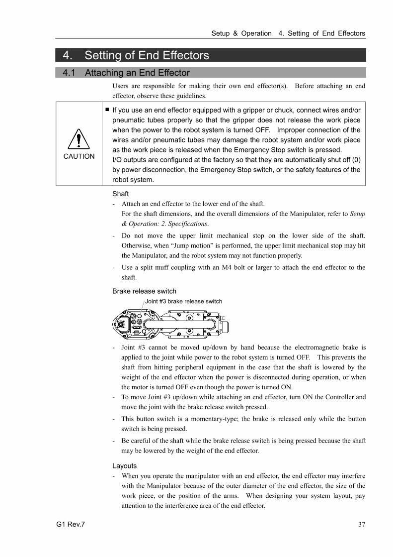
Brake release switch Joint #3 brake release switch
- Joint #3 cannot be moved up/down by hand because the electromagnetic brake is
applied to the joint while power to the robot system is turned OFF. This prevents the shaft from hitting peripheral equipment in the case that the shaft is lowered by the weight of the end effector when the power is disconnected during operation, or when the motor is turned OFF even though the power is turned ON.
- To move Joint #3 up/down while attaching an end effector, turn ON the Controller and move the joint with the brake release switch pressed.
- This button switch is a momentary-type; the brake is released only while the button switch is being pressed.
- Be careful of the shaft while the brake release switch is being pressed because the shaft may be lowered by the weight of the end effector.
Layouts - When you operate the manipulator with an end effector, the end effector may interfere
with the Manipulator because of the outer diameter of the end effector, the size of the work piece, or the position of the arms. When designing your system layout, pay attention to the interference area of the end effector.

Setup & Operation 4. Setting of End Effectors
38 G1 Rev.7
4.2 Weight and Inertia Settings To ensure optimum Manipulator performance, it is important to make sure that the load (weight of the end effector and work piece) and moment of inertia of the load are within the maximum rating for the Manipulator, and that Joint #4 does not become eccentric. If the load or moment of inertia exceeds the rating or if the load becomes eccentric, follow the steps below, “4.2.1Weight Setting” and “4.2.2 Inertia Setting” to set parameters. Setting parameters makes the PTP motion of the Manipulator optimal, reduces vibration to shorten the operating time, and improves the capacity for larger loads. In addition, it reduces persistent vibration produced when the moment of inertia of the end effector and work piece is larger that the default setting.
4.2.1 Weight Setting
CAUTION
■ The total weight of the end effector and the work piece must not exceed 1 kg (3-axis spec: 1.5 kg). The G1 series Manipulators (4-axis spec) are not designed to work with loads exceeding 1 kg (3-axis spec: 1.5 kg). Always set the Weight parameters according to the load. Setting a value that is smaller than the actual load may cause errors, excessive shock, insufficient function of the Manipulator, and/or shorten the life cycle of parts/mechanisms.
The acceptable weight capacity (end effector and work piece) in G1 series
Default rating Maximum 4-axis spec 0.5 kg 1 kg 3-axis spec 0.5 kg 1.5 kg
When the load (weight of the end effector and work piece) exceeds the rating, change the setting of Weight parameter. After the setting is changed, the maximum acceleration/deceleration speed of the robot system at PTP motion corresponding to the “Weight Parameter” is set automatically.
Load on the Shaft The load (weight of the end effector and work piece) on the shaft can be set by Weight parameter.
EPSON RC+
Enter a value into the [Load:] text box on the [Inertia] panel ([Tools] - [Robot Manager]). (You may also execute the Inertia command from the [Command Window].)

Setup & Operation 4. Setting of End Effectors
G1 Rev.7 39
Load on the Arm When you attach a camera or other devices to the arm, calculate the weight as the equivalent of the shaft. Then, add this to the load and enter the total weight to the Weight parameter. Equivalent Weight Formula
When you attach the equipment near Arm #2: When you attach the equipment to the end of Arm #2:
WM = M (L1)2/(L1+L2)2 WM = M (LM)2/(L2)2
WM M L1 L2 LM
: equivalent weight : weight of air valves etc. : length of Arm #1 : length of Arm #2 : distance from rotation center of Joint #2 to center of gravity
of camera etc.
Automatic speed setting by Weight 140
120
100
80
60
40
20
0 0.5 1.0 1.5 (kg) Weight setting
(%)
100 100 100 100
* The percentage in the graph is based on the speed at rated weight (0.5 kg) as 100%.
* 1.5 kg is only for 3-axis spec.
4-axis spec is up to 1.0 kg.
Automatic acceleration/deceleration setting by Weight 140
120
100
80
60
40
20
0 0.5 1.0 1.5 (kg) Weight setting
(%)
110 100
70 60
* The percentage in the graph is based on the acceleration / deceleration at rated weight (0.5 kg) as 100%.
* 1.5 kg is only for 3-axis spec.
4-axis spec is up to 1.0 kg.

Setup & Operation 4. Setting of End Effectors
40 G1 Rev.7
4.2.2 Inertia Setting Moment of Inertia and the Inertia Setting
The moment of inertia is defined as “the ratio of the torque applied to a rigid body and its resistance to motion”. This value is typically referred to as “the moment of inertia”, “inertia”, or “GD2”. When the Manipulator operates with additional objects (such as an end effector) attached to the shaft, the moment of inertia of load must be considered.
CAUTION
■ The moment of inertia of the load (weight of the end effector and work piece) must be 0.004 kgm2 or less. The G1 series Manipulators (4-axis spec) are not designed to work with a moment of inertia exceeding 0.004 kgm2. Always set the moment of inertia parameter to the correct moment of inertia. Setting a value that is smaller than the actual moment of inertia may cause errors, excessive shock, insufficient function of the Manipulator, and/or shorten the life cycle of parts/mechanisms.
The acceptable moment of inertia of load for G1 series Manipulator (4-axis spec) is 0.0003 kgm2 at the default rating and 0.004 kgm2 at the maximum. When the moment of inertia of the load exceeds the rating, change the setting of the moment of inertia parameter of the Inertia command. After the setting is changed, the maximum acceleration/deceleration speed of Joint #4 at PTP motion corresponding to the “moment of inertia” value is set automatically.
Moment of inertia of load on the shaft The moment of inertia of load (weight of the end effector and work piece) on the shaft can be set by the “moment of inertia” parameter of the Inertia command.
EPSON RC+
Enter a value into the [Load inertia:] text box on the [Inertia] panel ([Tools] - [Robot Manager]). (You may also execute the Inertia command from the [Command Window].)
Automatic acceleration/deceleration setting of Joint #4 by Inertia (moment of inertia)
140
120
100
80
60
40
20
(%)
120
40
20
10
0 0.001 0.002 0.003 0.004 (kg・m2) Moment of inertia setting

Setup & Operation 4. Setting of End Effectors
G1 Rev.7 41
Eccentric Quantity and the Inertia Setting
CAUTION
■ The eccentric quantity of load (weight of the end effector and work piece) must be 50 mm or less. The G1 series Manipulators are not designed to work with eccentric quantity exceeding 50 mm. Always set the eccentric quantity parameter according to the eccentric quantity. Setting a value that is smaller than the actual eccentric quantity may cause errors, excessive shock, insufficient function of the Manipulator, and/or shorten the life cycle of parts/mechanisms. The acceptable eccentric quantity of load in G1 series is 0 mm at the default rating and 50 mm at the maximum. When the eccentric quantity of load exceeds the rating, change the setting of eccentric quantity parameter of Inertia command. After the setting is changed, the maximum acceleration/deceleration speed of the Manipulator at PTP motion corresponding to the “eccentric quantity” is set automatically.
Position of load’s center of gravity
Rotation center
Eccentric quantity (50 mm or less)
Eccentric quantity of load on the shaft
The eccentric quantity of load (weight of the end effector and work piece) on the shaft can be set by “eccentric quantity” parameter of Inertia command.
EPSON RC+
Enter a value into the [Eccentricity:] text box on the [Inertia] panel ([Tools] - [Robot Manager]). (You may also execute the Inertia command from the [Command Window].)
Automatic acceleration/deceleration setting by Inertia (eccentric quantity)
120
100
80
60
40
20
0 10 20 30 40 50 (mm) Eccentricity setting
65
30 20
(%)
100 * The percentage in the graph is
based on the acceleration / deceleration at rated eccentricity (0 mm) as 100%.
* Please contact EPSON for over 50 mm.

Setup & Operation 4. Setting of End Effectors
42 G1 Rev.7
Calculating the Moment of Inertia Refer to the following examples of formulas to calculate the moment of inertia of load (end effector with work piece). The moment of inertia of the entire load is calculated by the sum of each part (a), (b), and (c).
Work piece (b) Work piece (c)
End effector (a)
Joint #3 shaft
Rotation center
Moment of inertia of end effector (a)
= Moment of inertia of work piece (b)
+ Moment of inertia of work piece (c)
+ Whole moment of inertia
The methods for calculating the moment of inertia for (a), (b), and (c) are shown below. Calculate the total moment of inertia using the basic formulas.
(a) Moment of inertia of a rectangular parallelepiped
h b
L
Mass (m)
Rectangular parallelepiped’s center of gravity Rotation center
m + m × L2 b2 + h2
12
(b) Moment of inertia of a cylinder
m + m × L2 r 2 2 Mass (m)
L
r
Cylinder’s center of gravity Rotation center

Setup & Operation 4. Setting of End Effectors
G1 Rev.7 43
(c) Moment of inertia of a sphere
m r 2+ m × L2 2 5
Sphere’s center of gravity
r
Mass (m)
L
Rotation center
4.3 Precautions for Auto Acceleration/Deceleration of Joint #3 When you move the Manipulator in horizontal PTP motion with Joint #3 (Z) at a high position, the motion time will be faster. When Joint #3 gets below a certain point, then auto acceleration/deceleration is used to reduce acceleration/deceleration. (Refer to the figure below.) The higher the position of the shaft is, the faster the motion acceleration/deceleration is. However, it takes more time to move Joint #3 up and down. Adjust the position of Joint #3 for the Manipulator motion after considering the relation between the current position and the destination position. The upper limit of Joint #3 during horizontal motion using Jump command can be set by the LimZ command.
Automatic acceleration/deceleration vs. Joint #3 position 120
100
80
60
40
20
0 -30 -60 -90 -120 -150 (mm) Shaft height
(%)
* Figures on the graph (%) are the proportion to the acceleration/deceleration speed at the shaft upper limit position.
100 100
30
When moving the Manipulator horizontally while the shaft is being lowered, it may cause over-shoot at the time of final positioning.
NOTE

Setup & Operation 5. Motion Range
44 G1 Rev.7
5. Motion Range
CAUTION
■ When setting up the motion range for safety, both the pulse range and mechanical stops must always be set at the same time.
The motion range is preset at the factory as explained in Setup & Operation: 5.4 Standard Motion Range. That is the maximum motion range of the Manipulator.
There are three methods for setting the motion range described as follows:
1. Setting by pulse range (for all joints)
2. Setting by mechanical stops (fix or change is not available)
3. Setting the Cartesian (rectangular) range in the X, Y coordinate system of the Manipulator (for Joints #1 and #2)
Mechanical stop
Rectangular range setting
Pulse range
Motion range Mechanical stop
When the motion range is changed due to layout efficiency or safety, follow the descriptions in 5.1 to 5.3 to set the range.
5.1 Motion Range Setting by Pulse Range (for All Joints) Pulses are the basic unit of Manipulator motion. The motion range of the Manipulator is controlled by the pulse range between the pulse lower limit and upper limit of each joint. Pulse values are read from the encoder output of the servo motor.
For the maximum pulse range, refer to the following sections. The pulse range must be set inside of the mechanical stop range.
5.1.1 Max. Pulse Range of Joint #1 5.1.2 Max. Pulse Range of Joint #2 5.1.3 Max. Pulse Range of Joint #3 5.1.4 Max. Pulse Range of Joint #4.
Once the Manipulator receives an operating command, it checks whether the target position specified by the command is within the pulse range before operating. If the target position is out of the set pulse range, an error occurs and the Manipulator does not move.
EPSON RC+
The pulse range can be set on the [Range] panel shown by selecting [Tools]-[Robot Manager]. (You may also execute the Range command from the [Command Window].)
NOTE

Setup & Operation 5. Motion Range
G1 Rev.7 45
5.1.1 Max. Pulse Range of Joint #1 The 0 (zero) pulse position of Joint #1 is the position where Arm #1 faces toward the positive (+) direction on the X-coordinate axis. When the 0 pulse is a starting point, the counterclockwise pulse value is defined as the positive (+) and the clockwise pulse value is defined as the negative (-).
+Y
+X 0 pulse
B B
A A
All models
A Max. Motion Range ± 125 deg. B Max. Pulse Range − 1019449 ~ + 6262329
5.1.2 Max. Pulse Range of Joint #2 The 0 (zero) pulse position of Joint #2 is the position where Arm #2 is in-line with Arm #1. With the 0 pulse as a starting point, the counterclockwise pulse value is defined as the positive (+) and the clockwise pulse value is defined as the negative (-).
B B
0 pulse
A A
4-axis spec G1-171S G1-171C G1-221S G1-221C
A Max. Motion Range ±140 deg. ±152 deg. ±149 deg. B Max. Pulse Range ± 2548623 ± 2767076 ± 2712463
3-axis spec G1-171SZ G1-171CZ G1-171CZ G1-221CZ
A Max. Motion Range ±135 deg. ±123 deg. ±135 deg. ±132 deg. B Max. Pulse Range ± 2457600 ± 2239147 ± 2457600 ± 2402987
Setup & Operation 5. Motion Range
46 G1 Rev.7
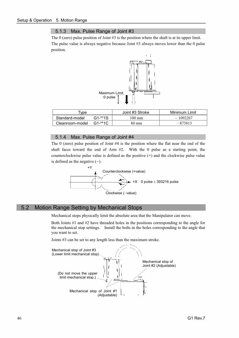
5.1.3 Max. Pulse Range of Joint #3 The 0 (zero) pulse position of Joint #3 is the position where the shaft is at its upper limit. The pulse value is always negative because Joint #3 always moves lower than the 0 pulse position.
Maximum Limit :0 pulse
Type Joint #3 Stroke Minimum Limit Standard-model G1-**1S 100 mm − 1092267 Cleanroom-model G1-**1C 80 mm -873813
5.1.4 Max. Pulse Range of Joint #4 The 0 (zero) pulse position of Joint #4 is the position where the flat near the end of the shaft faces toward the end of Arm #2. With the 0 pulse as a starting point, the counterclockwise pulse value is defined as the positive (+) and the clockwise pulse value is defined as the negative (-).
+Y
+X 0 pulse ± 393216 pulse
Clockwise (-value)
Counterclockwise (+value)
5.2 Motion Range Setting by Mechanical Stops Mechanical stops physically limit the absolute area that the Manipulator can move.
Both Joints #1 and #2 have threaded holes in the positions corresponding to the angle for the mechanical stop settings. Install the bolts in the holes corresponding to the angle that you want to set.
Joints #3 can be set to any length less than the maximum stroke.
Mechanical stop of Joint #1 (Adjustable)
Mechanical stop of Joint #3 (Lower limit mechanical stop)
(Do not move the upper limit mechanical stop.)
Mechanical stop of Joint #2 (Adjustable)
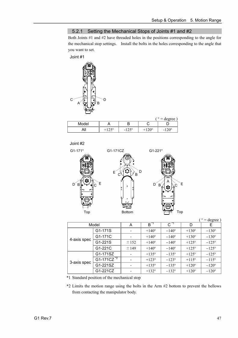
Setup & Operation 5. Motion Range
G1 Rev.7 47
5.2.1 Setting the Mechanical Stops of Joints #1 and #2 Both Joints #1 and #2 have threaded holes in the positions corresponding to the angle for the mechanical stop settings. Install the bolts in the holes corresponding to the angle that you want to set.
Joint #1
A C
B D
( ° = degree )
Model A B C D All +125° -125° +120° -120°
Joint #2
E C B D
G1-171CZ
A D B C E
G1-221*
D B C E
G1-171*
Top Bottom
Top ( ° = degree )
Model A B *1 C *1 D E
4-axis spec
G1-171S - +140° −140° +130° −130° G1-171C - +140° −140° +130° −130° G1-221S ±152 +140° −140° +125° −125° G1-221C ±149 +140° −140° +125° −125°
3-axis spec
G1-171SZ - +135° −135° +125° −125° G1-171CZ *2 - +123° −123° +115° −115° G1-221SZ - +135° −135° +120° −120° G1-221CZ - +132° −132° +120° −120°
*1 Standard position of the mechanical stop
*2 Limits the motion range using the bolts in the Arm #2 bottom to prevent the bellows from contacting the manipulator body.

Setup & Operation 5. Motion Range
48 G1 Rev.7
(1) Turn OFF the Controller.
(2) Install a hexagon socket head cap bolt into the hole corresponding to the setting angle, and tighten it.
Joint Hexagon socket head cap bolt (fully threaded)
The number of bolts
Recommended tightening torque
1 M6×10 2 17.6 N⋅m (180 kgf⋅cm) 2 M5×10 2 9.8 N⋅m (100 kgf⋅cm)
(3) Turn ON the Controller.
(4) Set the pulse range corresponding to the new positions of the mechanical stops.
Be sure to set the pulse range inside the positions of the mechanical stop range.
Example: Using G1-171S* The angle of Joint #1 is set from –120 degrees to +120 degrees. The angle of Joint #2 is set from -130 degrees to +130 degrees.
EPSON RC+
Execute the following commands from the [Command Window]. >JRANGE 1,-873814,6116694 'the pulse range of Joint #1 >JRANGE 2,-2366578,2366578 'the pulse range of Joint #2 >RANGE 'Checks the setting using Range -873814, 6116694,-2366578,2366578, −1092267 ,0, −393216, 393216
(5) Move the arm by hand until it touches the mechanical stops, and make sure that the arm does not hit any peripheral equipment during operation.
(6) Operate the joint changed at low speeds until it reaches the positions of the minimum and maximum pulse range. Make sure that the arm does not hit the mechanical stops. (Check the position of the mechanical stop and the motion range you set.)
Example: Using G1-171S* The angle of Joint #1 is set from -120 degrees to +120 degrees. The angle of Joint #2 is set from -130 degrees to +130 degrees.
EPSON RC+
Execute the following commands from the [Command Window]. >MOTOR ON ' Turns ON the motor
>LP ON ' Enters low-power mode >SPEED 5 ' Sets at low speeds >PULSE -873814,0,0,0 ' Moves to the min. pulse position of Joint #1 >PULSE 6116694,0,0,0 ' Moves to the max. pulse position of Joint #1 >PULSE 2621440,-2366578,0,0 ' Moves to the min. pulse position of Joint #2 >PULSE 2621440,2366578,0,0 ' Moves to the max. pulse position of Joint #2
The Pulse command (Go Pulse command) moves all joints to the specified positions at the same time. Specify safe positions after considering motion of not only the joints whose pulse range have been changed, but also other joints.
In this example, Joint #1 is moved to the center of its motion range (pulse value: 2621440) when checking Joint #2.
If the arm is hitting the mechanical stops or if an error occurs after the arm hits the mechanical stops, either reset the pulse range to a narrower setting or extend the positions of the mechanical stops within the limit.
NOTE
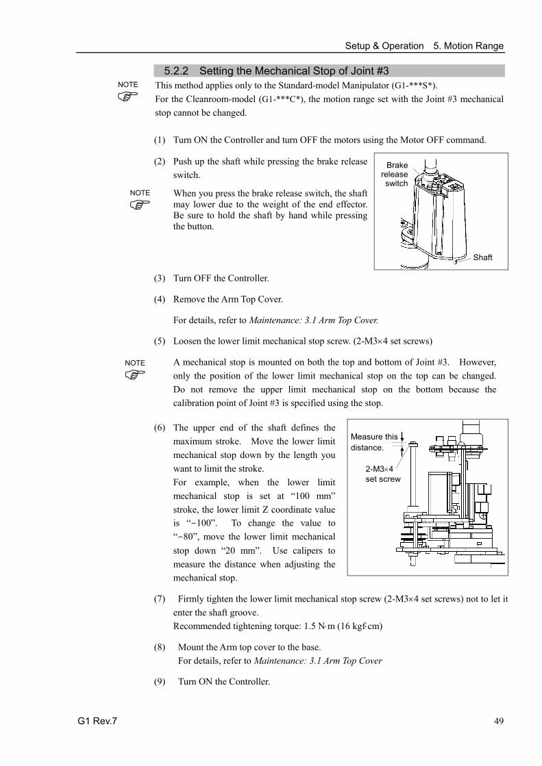
Setup & Operation 5. Motion Range
G1 Rev.7 49
5.2.2 Setting the Mechanical Stop of Joint #3 This method applies only to the Standard-model Manipulator (G1-***S*). For the Cleanroom-model (G1-***C*), the motion range set with the Joint #3 mechanical stop cannot be changed.
(1) Turn ON the Controller and turn OFF the motors using the Motor OFF command.
(2) Push up the shaft while pressing the brake release switch.
When you press the brake release switch, the shaft may lower due to the weight of the end effector. Be sure to hold the shaft by hand while pressing the button.
Shaft
Brake release switch
(3) Turn OFF the Controller.
(4) Remove the Arm Top Cover.
For details, refer to Maintenance: 3.1 Arm Top Cover.
(5) Loosen the lower limit mechanical stop screw. (2-M3×4 set screws)
A mechanical stop is mounted on both the top and bottom of Joint #3. However, only the position of the lower limit mechanical stop on the top can be changed. Do not remove the upper limit mechanical stop on the bottom because the calibration point of Joint #3 is specified using the stop.
(6) The upper end of the shaft defines the maximum stroke. Move the lower limit mechanical stop down by the length you want to limit the stroke. For example, when the lower limit mechanical stop is set at “100 mm” stroke, the lower limit Z coordinate value is “-100”. To change the value to “-80”, move the lower limit mechanical stop down “20 mm”. Use calipers to measure the distance when adjusting the mechanical stop.
2-M3×4 set screw
Measure this distance.
(7) Firmly tighten the lower limit mechanical stop screw (2-M3×4 set screws) not to let it
enter the shaft groove. Recommended tightening torque: 1.5 N⋅m (16 kgf⋅cm)
(8) Mount the Arm top cover to the base. For details, refer to Maintenance: 3.1 Arm Top Cover
(9) Turn ON the Controller.
NOTE
NOTE
NOTE

Setup & Operation 5. Motion Range
50 G1 Rev.7
(10) Move Joint #3 to its lower limit while pressing the brake release switch, and then check the lower limit position. Do not lower the mechanical stop too far. Otherwise, the joint may not reach a target position.
(11) Calculate the lower limit pulse value of the pulse range using the formula shown below and set the value.
The result of the calculation is always negative because the lower limit Z coordinate value is negative.
Lower limit of pulse (pulse)
= lower limit Z coordinate value (mm) / Resolution (mm/pulse)
** For the Joint #3 resolution, refer to the section Setup & Operation 2.4 Specifications.
EPSON RC+
Execute the following command from the [Command Window]. Enter the calculated value in X. >JRANGE 3,X,0 ' Sets the pulse range of Joint #3
(12) Using the Pulse command (Go Pulse command), move Joint #3 to the lower limit position of the pulse range at low speed. If the mechanical stop range is less than the pulse range, Joint #3 will hit the mechanical stop and an error will occur. When the error occurs, either change the pulse range to a lower setting or extend the position of the mechanical stop within the limit.
If it is difficult to check whether Joint #3 hits a mechanical stop, turn OFF the Controller and lift the arm top cover to check the condition causing the problem from the side.
EPSON RC+
Execute the following commands from the [Command Window]. Enter the value calculated in Step (10) in X. >MOTOR ON ' Turns ON the motor >SPEED 5 ' Sets low speed >PULSE 0,0,X,0 ' Moves to the lower limit-pulse position of Joint #3.
(In this example, all pulses except those for Joint #3 are “0”. Substitute these “0s” with the other pulse values specifying a position where there is no interference even when lowering Joint #3.)
NOTE

Setup & Operation 5. Motion Range
G1 Rev.7 51
5.3 Setting the Cartesian (Rectangular) Range in the XY Coordinate System of the Manipulator (for Joints #1 and #2)
Use this method to set the upper and lower limits of the X and Y coordinates.
This setting is only enforced by software. Therefore, it does not change the physical range. The maximum physical range is based on the position of the mechanical stops.
EPSON RC+
Set the XYLim setting on the [XYZ Limits] panel shown by selecting [Tools]-[Robot Manager]. (You may also execute the XYLim command from the [Command Window].)
5.4 Standard Motion Range
The following “motion range” diagrams show the standard (maximum) specification. When each Joint motor is under servo control, the center of Joint #3’s (shaft’s) lowest point moves in the areas shown in the figure.
“Area limited by mechanical stop” is the area where the center of Joint #3’s lowest point can be moved when each joint motor is not under servo control.
“Mechanical stop” sets the limited motion range so that the center of Joint #3 cannot move beyond the area mechanically.
“Maximum space” is the area that contains the farthest reach of the arms. If the maximum radius of the end effector is over 60 mm, add the “Area limited by mechanical stop” and “radius of the end effector”. The total value is specified as the maximum area.
For the motion area figures, refer to Setup & Operation 3.3 Mounting Dimensions.

Setup & Operation 5. Motion Range
52 G1 Rev.7

Maintenance This volume contains maintenance procedures with safety precautions for G1 series Manipulators.

54

Maintenance 1. Safety Maintenance
G1 Rev.7 55
1. Safety Maintenance
Please read this chapter, this manual, and other relevant manuals carefully to understand safe maintenance procedures before performing any routine maintenance. Only authorized personnel who have taken safety training should be allowed to maintain the robot system. Safety training is the program for industrial robot operators that follows the laws and regulations of each nation. The personnel who have taken safety training acquire knowledge of industrial robots (operations, teaching, etc.), knowledge of inspections, and knowledge of related rules/regulations. The personnel who have completed the robot system-training and maintenance- training classes held by the manufacturer, dealer, or locally-incorporated company are allowed to maintain the robot system.
WARNING
■ Do not remove any parts that are not covered in this manual. Follow the maintenance procedure strictly as described in this manual. Improper removal of parts or improper maintenance may not only cause improper function of the robot system but also serious safety problems.
■ Keep away from the Manipulator while the power is ON if you have not taken the training courses. Do not enter the operating area while the power is ON. Entering the operating area with the power ON is extremely hazardous and may cause serious safety problems as the Manipulator may move even it seems to be stopped.
■ When you check the operation of the Manipulator after replacing parts, be sure to check it while you are outside of the safeguarded area. Checking the operation of the Manipulator while you are inside of the safeguarded area may cause serious safety problems as the Manipulator may move unexpectedly.
■ Before operating the robot system, make sure that both the Emergency Stop switches and safeguard switch function properly. Operating the robot system when the switches do not function properly is extremely hazardous and may result in serious bodily injury and/or serious damage to the robot system as the switches cannot fulfill their intended functions in an emergency.
WARNING
■ To shut off power to the robot system, pull out the power plug from the power source. Be sure to connect the AC power cable to a power receptacle. DO NOT connect it directly to a factory power source.
■ Before performing any replacement procedure, turn OFF the Controller and related equipment, and then pull out the power plug from the power source. Performing any replacement procedure with the power ON is extremely hazardous and may result in electric shock and/or malfunction of the robot system.

Maintenance 1. Safety Maintenance
56 G1 Rev.7
CAUTION
■ Be sure to connect the cables properly. Do not allow unnecessary strain on the cables. (Do not put heavy objects on the cables. Do not bend or pull the cables forcibly.) The unnecessary strain on the cables may result in damage to the cables, disconnection, and/or contact failure. Damaged cables, disconnection, or contact failure is extremely hazardous and may result in electric shock and/or improper function of the robot system.
2. General Maintenance This chapter describes maintenance inspections and procedures. Performing maintenance inspections and procedures properly is essential for preventing trouble and ensuring safety. Be sure to perform the maintenance inspections in accordance with the schedule.
2.1 Maintenance Inspection 2.1.1 Schedule for Maintenance Inspection
Inspection points are divided into five stages: daily, monthly, quarterly, biannual, and annual. The inspection points are added every stage. If the Manipulator is operated for 250 hours or longer per month, the inspection points must be added every 250 hours, 750 hours, 1500 hours, and 3000 hours operation.
Inspection Point
Daily inspection
Monthly inspection
Quarterly inspection
Biannual inspection
Annual inspection
Overhaul
1 month (250 h)
Inspect every day
√
2 months (500 h) √
3 months (750 h) √ √
4 months (1000 h) √
5 months (1250 h) √
6 months (1500 h) √ √ √
7 months (1750 h) √
8 months (2000 h) √
9 months (2250 h) √ √
10 months (2500 h) √
11 months (2750 h) √
12 months (3000 h) √ √ √ √
13 months (3250 h) √
…
…
…
…
…
…
…
20000 h √
h = hour

Maintenance 2. General Maintenance
G1 Rev.7 57
2.1.2 Inspection Point
Inspection While the Power is OFF (Manipulator is not operating)
Inspection Point Inspection Place Daily Monthly Quarterly Biannual Annual
Check looseness or backlash of bolts/screws. Tighten them if necessary. (For the tightening torque, refer to Maintenance: 2.4 Tightening Hexagon Socket Head Cap Bolts.)
End effector mounting bolts √ √ √ √ √ Manipulator mounting bolts √ √ √ √ √ Each arm locking bolts √ √ √ √ √ Bolts/screws around shaft √ Bolts/screws securing motors, reduction gear units, etc.
√
Check looseness of connectors. If the connectors are loosen, push it securely or tighten.
External connectors on Manipulator (on the connector plates etc.)
√ √ √ √ √
Manipulator cable unit √ √ √ √
Visually check for external defects. Clean up if necessary.
External appearance of Manipulator
√ √ √ √ √
External cables √ √ √ √ Check for bends or improper location. Repair or place it properly if necessary.
Safeguard etc. √ √ √ √ √
Check tension of timing belts. Tighten it if necessary.
Inside of Arm #2 √ √
Grease conditions Refer to Maintenance: 2.3 Greasing. Battery - Replace every 3 years
Inspection While the Power is ON (Manipulator is operating)
Inspection Point Inspection Place Daily Monthly Quarterly Biannual Annual Check motion range Each joint √ Move the cables back and forth lightly to check whether the cables are disconnected.
External cables (including cable unit of the Manipulator)
√ √
Push each arm in MOTOR ON status to check whether backlash exists.
Each arm √
Check whether unusual sound or vibration occurs.
Whole √ √ √ √ √
Measure the accuracy repeatedly by a gauge.
Whole √
Turn ON and OFF the Brake Release switch and check the sound of the electromagnetic brake. If there is no sound, replace the brake.
Brake √ √ √ √ √

Maintenance 2. General Maintenance
58 G1 Rev.7
2.2 Overhaul The parts for the manipulator joints may cause accuracy decline or malfunction due to deterioration of the manipulator resulting from long term use. In order to use the manipulator for a long term, it is recommended to overhaul the parts (parts replacement).
Although the degree of deterioration varies depending on usage condition and the load applied on the Manipulator, timing of the overhaul is 20,000 operation hours of the Manipulator as a rough indication.
The manipulator operation hours can be checked in [Controller Status Viewer] dialog -[Motor On Hours].
(1) Select EPSON RC+ menu-[Tools]-[Controller] to open the [Controller Tools] dialog.
(2) Click the <View Controller Status> button to open the [Browse For Folder] dialog.
(3) Select the folder where the information is stored.
(4) Click <OK> to view the [Controller Status Viewer] dialog.
(5) Select [Robot] from the tree menu on the left side (Dialog image: EPSON RC+ 7.0)
For the parts subject to overhaul, refer to Maintenance 14. Maintenance Parts List.
For details of replacement of each part, refer to the Maintenance section.
Please contact our service center or distributors of your region for further information.
CAUTION
■
Overhaul timing is based on an assumption that all joints are operated for equal distance. If a particular joint has a high duty or high load, it is recommended to overhaul all joints (as many as possible) before exceeding 20,000 operation hours with the joint as a basis.
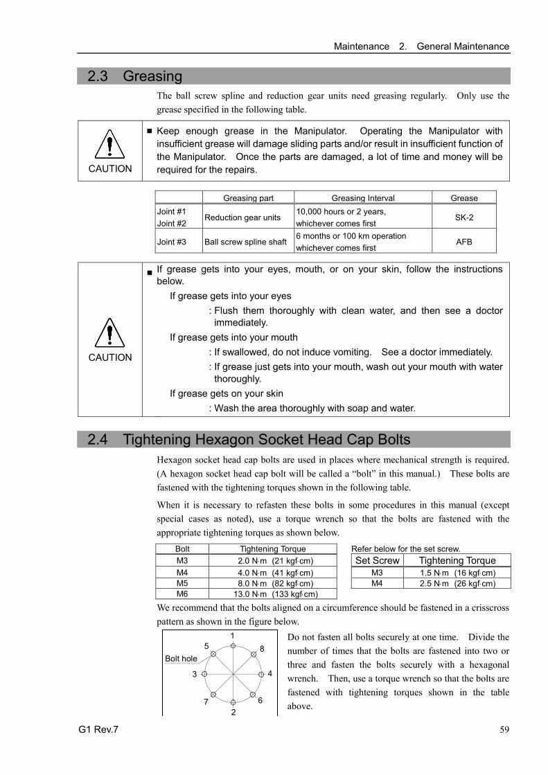
Maintenance 2. General Maintenance
G1 Rev.7 59
2.3 Greasing The ball screw spline and reduction gear units need greasing regularly. Only use the grease specified in the following table.
CAUTION
■ Keep enough grease in the Manipulator. Operating the Manipulator with insufficient grease will damage sliding parts and/or result in insufficient function of the Manipulator. Once the parts are damaged, a lot of time and money will be required for the repairs. Greasing part Greasing Interval Grease Joint #1 Joint #2
Reduction gear units 10,000 hours or 2 years, whichever comes first
SK-2
Joint #3 Ball screw spline shaft 6 months or 100 km operation whichever comes first
AFB
CAUTION
■ If grease gets into your eyes, mouth, or on your skin, follow the instructions below.
If grease gets into your eyes : Flush them thoroughly with clean water, and then see a doctor immediately.
If grease gets into your mouth : If swallowed, do not induce vomiting. See a doctor immediately. : If grease just gets into your mouth, wash out your mouth with water thoroughly.
If grease gets on your skin : Wash the area thoroughly with soap and water.
2.4 Tightening Hexagon Socket Head Cap Bolts
Hexagon socket head cap bolts are used in places where mechanical strength is required. (A hexagon socket head cap bolt will be called a “bolt” in this manual.) These bolts are fastened with the tightening torques shown in the following table.
When it is necessary to refasten these bolts in some procedures in this manual (except special cases as noted), use a torque wrench so that the bolts are fastened with the appropriate tightening torques as shown below.
Bolt Tightening Torque
Refer below for the set screw. M3 2.0 N⋅m (21 kgf⋅cm) Set Screw Tightening Torque M4 4.0 N⋅m (41 kgf⋅cm) M3 1.5 N⋅m (16 kgf⋅cm) M5 8.0 N⋅m (82 kgf⋅cm) M4 2.5 N⋅m (26 kgf⋅cm) M6 13.0 N⋅m (133 kgf⋅cm)
We recommend that the bolts aligned on a circumference should be fastened in a crisscross pattern as shown in the figure below.
1 5
3
7 2
6
4
8 Bolt hole
Do not fasten all bolts securely at one time. Divide the number of times that the bolts are fastened into two or three and fasten the bolts securely with a hexagonal wrench. Then, use a torque wrench so that the bolts are fastened with tightening torques shown in the table above.
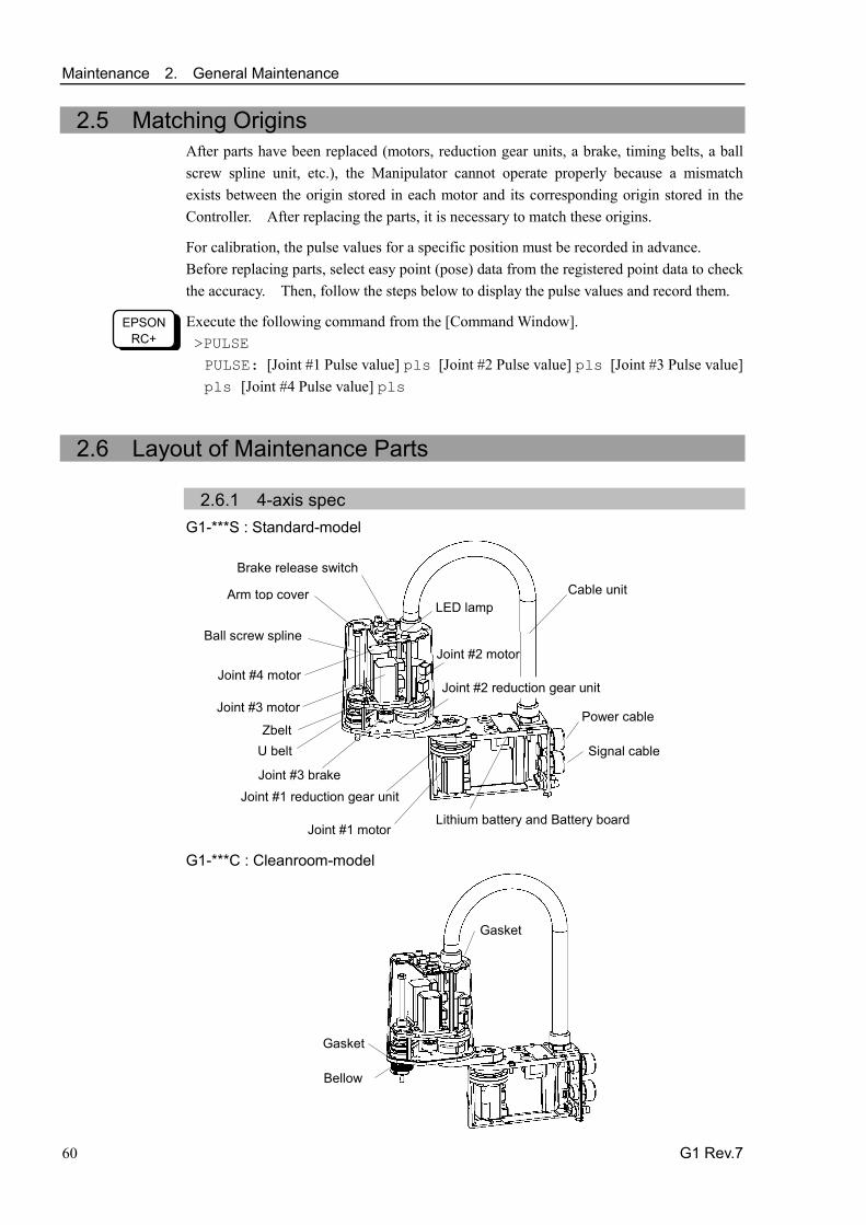
Maintenance 2. General Maintenance
60 G1 Rev.7
2.5 Matching Origins After parts have been replaced (motors, reduction gear units, a brake, timing belts, a ball screw spline unit, etc.), the Manipulator cannot operate properly because a mismatch exists between the origin stored in each motor and its corresponding origin stored in the Controller. After replacing the parts, it is necessary to match these origins.
For calibration, the pulse values for a specific position must be recorded in advance. Before replacing parts, select easy point (pose) data from the registered point data to check the accuracy. Then, follow the steps below to display the pulse values and record them.
EPSON RC+
Execute the following command from the [Command Window]. >PULSE PULSE: [Joint #1 Pulse value] pls [Joint #2 Pulse value] pls [Joint #3 Pulse value] pls [Joint #4 Pulse value] pls
2.6 Layout of Maintenance Parts
2.6.1 4-axis spec G1-***S : Standard-model
Joint #4 motor
Joint #1 motor
Joint #2 reduction gear unit
Joint #1 reduction gear unit
LED lamp
Ball screw spline
Joint #3 motor
Cable unit
Zbelt U belt
Joint #2 motor
Arm top cover
Joint #3 brake
Lithium battery and Battery board
Brake release switch
Power cable
Signal cable
G1-***C : Cleanroom-model
Bellow
Gasket
Gasket

Maintenance 2. General Maintenance
G1 Rev.7 61
2.6.2 3-axis spec G1-***SZ : Standard-model
Joint #1 motor
Joint #2 reduction gear unit
Joint #1 reduction gear unit
LED lamp
Ball screw spline unit
Joint #3 motor
Cable unit
Zbelt
Joint #2 motor
Arm top cover
Joint #3 brake
Lithium battery and Battery board
Power cable
Signal cable
G1-***CZ : Cleanroom-model
Bellows
Bellows
Gasket
Gasket

Maintenance 3. Covers
62 G1 Rev.7
3. Covers All procedures for removing and installing covers in maintenance are described in this chapter.
WARNING
■ Do not insert or pull out the motor connectors while the power to the robot system is turned ON. Inserting or pulling out the motor connectors with the power ON is extremely hazardous and may result in serious bodily injury as the Manipulator may move abnormally, and also may result in electric shock and/or malfunction of the robot system.
■ To shut off power to the robot system, pull out the power plug from the power source. Be sure to connect the AC power cable to a power receptacle. DO NOT connect it directly to a factory power source.
■ Before performing any replacement procedure, turn OFF the Controller and related equipment, and then pull out the power plug from the power source. Performing any replacement procedure with the power ON is extremely hazardous and may result in electric shock and/or malfunction of the robot system.
■ Be careful not to get any foreign substances in the Manipulator, connectors, and pins during maintenance. Turning ON the power to the robot system when any foreign substances exist in them is extremely hazardous and may result in electric shock and/or malfunction of the robot system.
Name Quantity Note
Maintenance parts
Arm Top Cover 1 Arm Top Cover for Cleanroom-model 1 Gasket unit 1 Only for Cleanroom-model
Tools
Hexagonal wrench (width across flats: 3 mm) 1 For M4 screw Tightening Torque: 0.9 N⋅m (9.2 kgf⋅cm)
Cross-point screwdriver 1
For M4 truss screw Tightening Torque: 0.4 N⋅m (4.1 kgf⋅cm) For bellows removal
Wiping cloth 1 For wiping adhesive
Arm top cover
Connector plate
Connector sub plate
User plate

Maintenance 3. Covers
G1 Rev.7 63
3.1 Arm Top Cover
CAUTION
■ Do not remove the arm top cover forcibly. Removing the cover forcibly may result in damage to the cables, disconnection, and/or contact failure. Damaged cables, disconnection, or contact failure is extremely hazardous and may result in electric shock and/or improper function of the robot system.
■ When installing the cover, be careful not to allow the cables to interfere with the cover mounting and do not bend these cables forcibly to push them into the cover. Unnecessary strain on cables may result in damage to the cables, disconnection, and/or contact failure. Damaged cables, disconnection, or contact failure is extremely hazardous and may result in electric shock and/or improper function of the robot system. When routing the cables, observe the cable locations after removing the cover. Be sure to place the cables back to their original locations.
Unscrew the arm top cover mounting bolts, and then lift the cover.
When bellows are installed to the manipulator, remove / install the arm top cover and then remove / install the upper bellows.
4-M4×12 : Truss
4-M4×8 : Hexagonal
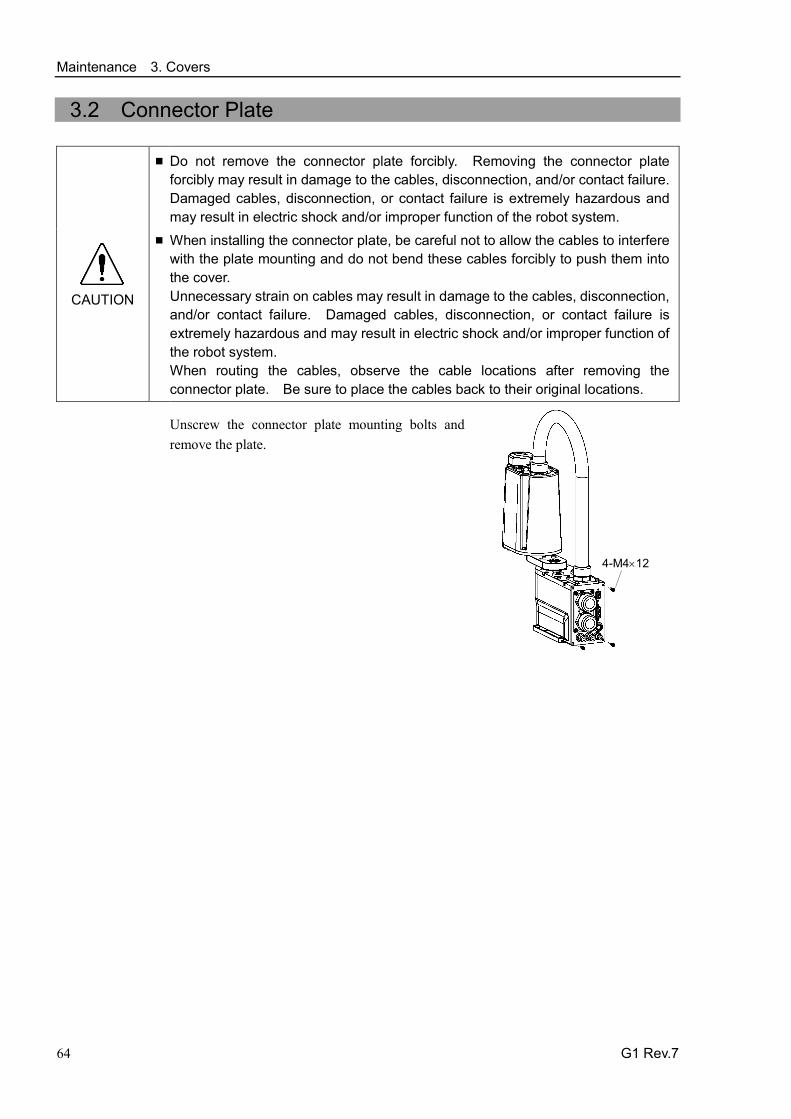
Maintenance 3. Covers
64 G1 Rev.7
3.2 Connector Plate
CAUTION
■ Do not remove the connector plate forcibly. Removing the connector plate forcibly may result in damage to the cables, disconnection, and/or contact failure. Damaged cables, disconnection, or contact failure is extremely hazardous and may result in electric shock and/or improper function of the robot system.
■ When installing the connector plate, be careful not to allow the cables to interfere with the plate mounting and do not bend these cables forcibly to push them into the cover. Unnecessary strain on cables may result in damage to the cables, disconnection, and/or contact failure. Damaged cables, disconnection, or contact failure is extremely hazardous and may result in electric shock and/or improper function of the robot system. When routing the cables, observe the cable locations after removing the connector plate. Be sure to place the cables back to their original locations.
Unscrew the connector plate mounting bolts and remove the plate.
4-M4×12
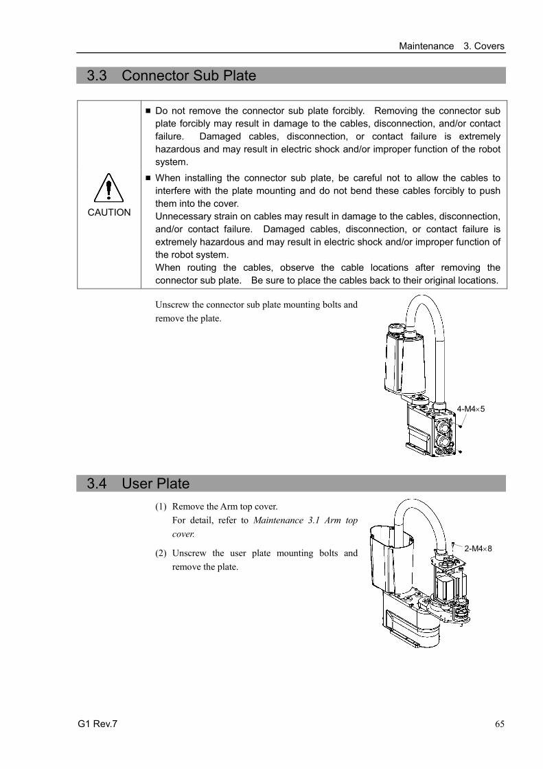
Maintenance 3. Covers
G1 Rev.7 65
3.3 Connector Sub Plate
CAUTION
■ Do not remove the connector sub plate forcibly. Removing the connector sub plate forcibly may result in damage to the cables, disconnection, and/or contact failure. Damaged cables, disconnection, or contact failure is extremely hazardous and may result in electric shock and/or improper function of the robot system.
■ When installing the connector sub plate, be careful not to allow the cables to interfere with the plate mounting and do not bend these cables forcibly to push them into the cover. Unnecessary strain on cables may result in damage to the cables, disconnection, and/or contact failure. Damaged cables, disconnection, or contact failure is extremely hazardous and may result in electric shock and/or improper function of the robot system. When routing the cables, observe the cable locations after removing the connector sub plate. Be sure to place the cables back to their original locations.
Unscrew the connector sub plate mounting bolts and remove the plate.
4-M4×5
3.4 User Plate (1) Remove the Arm top cover.
For detail, refer to Maintenance 3.1 Arm top cover.
(2) Unscrew the user plate mounting bolts and remove the plate.
2-M4×8

Maintenance 4. Cable
66 G1 Rev.7
4. Cable
WARNING
■ Do not insert or pull out the motor connectors while the power to the robot system is turned ON. Inserting or pulling out the motor connectors with the power ON is extremely hazardous and may result in serious bodily injury as the Manipulator may move abnormally, and also may result in electric shock and/or malfunction of the robot system.
■ To shut off power to the robot system, pull out the power plug from the power source. Be sure to connect the AC power cable to a power receptacle. DO NOT connect it directly to a factory power source.
■ Before performing any replacement procedure, turn OFF the Controller and related equipment, and then pull out the power plug from the power source. Performing any replacement procedure with the power ON is extremely hazardous and may result in electric shock and/or malfunction of the robot system.
■ Be careful not to get any foreign substances in the Manipulator, connectors, and pins during maintenance. Turning ON the power to the robot system when any foreign substances exist in them is extremely hazardous and may result in electric shock and/or malfunction of the robot system.
CAUTION
■ Be sure to connect the cables properly. Do not allow unnecessary strain on the cables. (Do not put heavy objects on the cables. Do not bend or pull the cables forcibly.) The unnecessary strain on the cables may result in damage to the cables, disconnection, and/or contact failure. Damaged cables, disconnection, or contact failure is extremely hazardous and may result in electric shock and/or improper function of the robot system.

Maintenance 4. Cable
G1 Rev.7 67
4.1 Replacing Cable Unit Since the power is supplied to each motor from the lithium battery installed on the battery board via the battery connector, the position data will not be lost when the Controller is turned OFF. When the battery connectors are disconnected, the position data will be lost, and EPSON RC+ will display an error when the Controller is turned ON.
If the error occurs, execute the calibration of all joints and axes. For details of the calibration, refer to Maintenance 13. Calibration.
Name Quantit
y Note
Maintenance
parts
Cable unit 1
Battery Unit (Lithium battery) 1 R13ZA00600300
Tools
Hexagonal wrench (width across flats: 3 mm) 1 For M4 screw Spanner (width across flats: 5 mm) 1 For D-sub connector removal Nut screwdriver (width across flats: 5 mm) 1 For D-sub connector removal Cross-point screwdriver 1 Torque wrench 1 Nippers 1 For cutting wire tie
Alcohol Proper
quantity For wiping grease
Wiping cloth 1 For wiping grease
Cable unit

Maintenance 4. Cable
68 G1 Rev.7
CAUTION
■ If the connectors have been disconnected during the replacement of the cable unit, be sure to reconnect the connectors to their proper positions. Refer to the block diagrams. Improper connection of the connectors may result in improper function of the robot system. For details on the connections, refer to Maintenance: 4.2 Wiring Diagrams.
■ When installing the cover, be careful not to allow the cables to interfere with the cover mounting and do not bend these cables forcibly to push them into the cover. Unnecessary strain on cables may result in damage to the cables, disconnection, and/or contact failure. Damaged cables, disconnection, or contact failure is extremely hazardous and may result in electric shock and/or improper function of the robot system. When routing the cables, observe the cable locations after removing the cover. Be sure to place the cables back to their original locations.
■ Be sure to connect the cables properly. Do not allow unnecessary strain on the cables. (Do not put heavy objects on the cables. Do not bend or pull the cables forcibly.) The unnecessary strain on the cables may result in damage to the cables, disconnection, and/or contact failure. Damaged cables, disconnection, or contact failure is extremely hazardous and may result in electric shock and/or improper function of the robot system.

Maintenance 4. Cable
G1 Rev.7 69
Cable unit Removal
(1) Turn ON the Controller and change the motor to OFF status (MOTOR OFF).
(2) Press and hold the brake release switch to let the shaft down. Be sure to keep enough space and prevent the end effector hitting any peripheral equipment.
The brake release switch affects only Joint #3. When the brake release switch is pressed, the brake for Joint #3 is released.
Be careful of the shaft falling while the brake release switch is being pushed because it may be lowered by the weight of an end effector.
(3) Turn OFF the Controller and disconnect the power cable and signal cable connectors from thee controller.
(4) Remove the arm top cover. For details, refer to Maintenance: 3.1 Arm Top Cover.
(5) Connect the spare battery to connector X60C. - Use the battery unit as the spare battery.
- The position data of Joint #2, #3, #4 motor is stored with the battery on base. Connect the spare battery otherwise the Joint #2, #3, #4 position data will be lost.
(6) Cut off the wire tie binding cables on the arm side.
(7) Remove the 10 connectors and ground wire on the arm side.
Connector: X21, X22, X31, X32, X33, X41, XB10, X221, X231, X241
- Remember the cable layout so that the cables can be reconnected correctly after replacement.
(8) Remove the screw securing the user plate and remove the user plate from Arm #2. For details, refer to Maintenance: 3.4 User Plate.
(9) Remove the connectors of the following from the user plate.
D-sub cable, Air tube, Brake release switch
Be careful not to lose the set screws of D-sub cable because they are so small.
To pull out the air tube, press the ring of fittings. (ø6×2, ø4×2)
- Remember the cable layout so that the cables can be reconnected correctly after replacement.
(10) Remove the duct fitting from the user plate and pull out the cables.
User plate
Duct fittings
(11) Remove the connector plate. For details, refer to Maintenance: 3.2 Connector Plate.
NOTE

Maintenance 4. Cable
70 G1 Rev.7
(12) Remove the cables from the connector plate. Air tube, D-sub cable 6 connectors : X10, X20, X30, X111, X121, X131
Be sure to keep the connectors of the battery board connected while replacing the cables. Otherwise, you will lose the position data and must execute the calibration again.
- Remember the cable layout so that the cables can be reconnected correctly after replacement.
(13) Remove the ground wire from the base.
(14) Remove the mounting plate of the cable unit. Mounting plate of cable unit 4-M4×12
(15) Remove the wire tie binding the cables on the base side.
(16) Pull out the connector X62 from the battery board. (X62: lower of two connectors)
Be sure to keep the connector X61 (upper one) of the battery board connected. Otherwise, you will lose the position data of the Joint #1 motor and must execute the calibration again. Do not remove the connector X61.
- Remember the cable layout so that the cables can be reconnected correctly after replacement.
(17) Remove the duct fittings from the mounting plate of the cable unit.
Mounting plate of cable unit
Duct fittings
NOTE

Maintenance 4. Cable
G1 Rev.7 71
Cable unit Installation
(1) Pass the cables through the user plate and secure the duct fittings. Be careful of the cable support direction.
User plate
Duct fittings
(2) Mount the air tube, ground wire, and D-sub cable to the user plate.
(3) Pass the cables though the mounting plate of the cable unit and secure the duct fittings. Mounting plate of
cable unit
Duct fittings
(4) Connect the connector X62 to the battery board.
(5) Secure the ground wire to the base.
(6) Re-bundle the wire tie removed in the removal step (16).
(7) Mount the cable unit to the J1 flange. Be careful of the cable support direction.
Cable support
(8) Mount the following to the inner side of connector plate, connector sub plate.
Air tube, ground wire, D-sub cable Joint #1 signal cable connector, power cable connector: X10, X111 4 connectors: X20, X30, X121, X131
(9) Mount the user plate to Arm #2. For details, refer to Maintenance: 3.4 User Plate.
(10) Mount the ground wire to Arm #2.
(11) Connect the connectors on the arm side. Connectors: X21, X22, X31, X32, X33, X41, XB10, X221, X231, X241
(12) Remove the spare battery connected to X60C.
(13) Re-bundle the wire tie removed in the removal step (6).
Maintenance 4. Cable
72 G1 Rev.7
(14) Mount the connector plate to the base. For details, refer to Maintenance: 3.2 Connector Plate.
(15) Set the Arm #2 cover without cables caught and secure it. For details, refer to Maintenance: 3.1 Arm Top Cover.
(16) If a connector falls out from the battery board, you must execute the calibration for all axes.

Maintenance 4. Cable
G1 Rev.7 73
4.2 Wiring Diagrams
4.2.1 Signal Cable
Det
ail B
oard
Dia
gram
Cab
le c
olor
Pi
nk
Red
Vi
olet
W
hite
Ye
llow
Cod
e P R
V W
Y
Cab
le c
olor
Bl
ack
Brow
n G
reen
Bl
ue
Ora
nge
Cod
e B BR
G
L O

Maintenance 4. Cable
74 G1 Rev.7
4.2.2 Power Cable
C
able
col
or
Pink
Red
Viol
et
Whi
te
Cod
e
P R
V W
Cab
le c
olor
Blac
k
Brow
n
Gre
en
Blue
Cod
e
B BR
G L
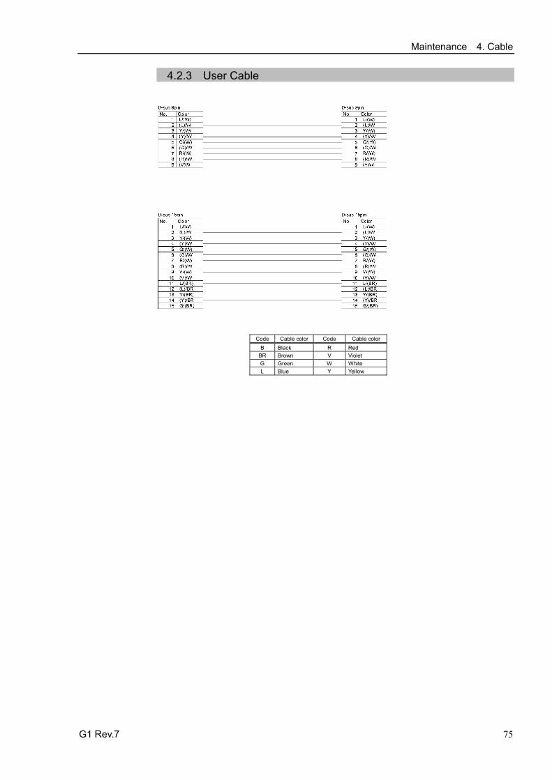
Maintenance 4. Cable
G1 Rev.7 75
4.2.3 User Cable
Code Cable color Code Cable color B Black R Red
BR Brown V Violet G Green W White L Blue Y Yellow

Maintenance 4. Cable
76 G1 Rev.7
4.3 Replacing M/C Cable Since the power is supplied to each motor from the lithium battery installed on the battery board via the battery connector, the position data will not be lost when the Controller is turned OFF. When the battery connectors are disconnected, the position data will be lost, and EPSON RC+ will display an error when the Controller is turned ON.
If the error occurs, execute the calibration of all joints and axes. For details, refer to Maintenance: 13. Calibration.
Name Quantity Note
Maintenance parts M/C Cable 1
Each manipulator model (Refer to Maintenance: 14. Maintenance parts)
Tools Hexagonal wrench (width across flats: 3 mm) 1 For M4 screw Torque wrench 1
CAUTION
■ If the connectors have been disconnected during the replacement of the cable unit, be sure to reconnect the connectors to their proper positions. Refer to the block diagrams. Improper connection of the connectors may result in improper function of the robot system. For details on the connections, refer to Maintenance: 4.2 Wiring Diagrams.
■ When installing the cover, be careful not to allow the cables to interfere with the cover mounting and do not bend these cables forcibly to push them into the cover. Unnecessary strain on cables may result in damage to the cables, disconnection, and/or contact failure. Damaged cables, disconnection, or contact failure is extremely hazardous and may result in electric shock and/or improper function of the robot system. When routing the cables, observe the cable locations after removing the cover. Be sure to place the cables back to their original locations.
■ Be sure to connect the cables properly. Do not allow unnecessary strain on the cables. (Do not put heavy objects on the cables. Do not bend or pull the cables forcibly.) The unnecessary strain on the cables may result in damage to the cables, disconnection, and/or contact failure. Damaged cables, disconnection, or contact failure is extremely hazardous and may result in electric shock and/or improper function of the robot system.
NOTE

Maintenance 4. Cable
G1 Rev.7 77
M/C Cable
M/C Cable Removal
(1) Turn OFF the Controller.
(2) Disconnect the power cable and signal cable connectors from the controller.
(3) Remove the Connector Sub Plate. For details, refer to Maintenance: 3.3 Connector Sub Plate.
Do not pull the Sub plate forcibly. The M/C cables are still attached to the plate.
(4) Disconnect the connectors.
Connector: x10, x20, x30, x111, x121, X131
Each connector has a unique number. Each connector has a different shape.
Do not disconect the buttary connector connected with the battery board. Otherwise, the calibration must be executed.
M/C Cable Installation
(5) Connect new M/C cable connectors to those of the Cable Unit.
(Connect to the connectors of the Cable Unit with the same number.)
(6) Mount the Connector Sub Plate. For details, refer to Maintenance: 3.3 Connector SubPlate.
(7) Connect the power cable and signal cable connectors to the controller.
(8) Turn ON the Controller.
(9) If the connector falls off from the battery, execute the calibration for All Joint. For details, refer to Maintenance: 13 Calibration.
NOTE
NOTE
NOTE

Maintenance 5. Arm #1
78 G1 Rev.7
5. Arm #1
WARNING
■ Do not insert or pull out the motor connectors while the power to the robot system is turned ON. Inserting or pulling out the motor connectors with the power ON is extremely hazardous and may result in serious bodily injury as the Manipulator may move abnormally, and also may result in electric shock and/or malfunction of the robot system.
■ To shut off power to the robot system, pull out the power plug from the power source. Be sure to connect the AC power cable to a power receptacle. DO NOT connect it directly to a factory power source.
■ Before performing any replacement procedure, turn OFF the Controller and related equipment, and then pull out the power plug from the power source. Performing any replacement procedure with the power ON is extremely hazardous and may result in electric shock and/or malfunction of the robot system.
CAUTION
■ Be careful not to apply excessive shock to the motor shaft when replacing the motors. The shock may shorten the life cycle of the motors and encoder and/or damage them.
■ Never disassemble the motor and encoder. A disassembled motor and encoder will cause a positional gap and cannot be used again.
After parts have been replaced (motors, reduction gear units, brakes, timing belts, ball screw spline unit, etc.), the Manipulator cannot operate properly because a mismatch exists between the origin stored in each motor and its corresponding origin stored in the Controller. After replacing the parts, it is necessary to match these origins. The process of aligning the two origins is called “Calibration”.
Refer to Maintenance: 13. Calibration to perform the calibration.
Joint #1 motor
Joint #1 reduction gear

Maintenance 5. Arm #1
G1 Rev.7 79
5.1 Replacing Joint #1 Motor
Name Quantity Note Maintenance
parts AC Servo Motor (50 W) 1 R13B000621
Tools
Hexagonal wrench (width across flats: 1.5 mm) 1 For M3 set screw Hexagonal wrench (width across flats: 3 mm) 1 For M4 screw Hexagonal wrench (width across flats: 5 mm) 1 For M6 screw Torque wrench 1 Wiping cloth 1 For wiping grease
Joint #1 motor Removal
(1) Remove Arm #1 from the base.
Put Arm #1 softly on the floor to avoid a shock to the arm.
(2) Remove the connector plate. For details, refer to Maintenance: 3.4 Connector Plate.
(3) Disconnect the following connectors. Connectors X111, X10 (Hold the claw to remove.) Connector X61
(4) Remove the Joint #1 flange with the Joint #1 unit from the base.
The base and Joint #1 flange has been aligned to the assembly position with the positioning pin. Be careful not to lose the positioning pin.
2-M4×45 4-M6×15
(5) Loosen the screw of motor flange on the Joint
#1 flange. Remove the Joint #1 unit.
4-M4×40
Joint #1 motor unit

Maintenance 5. Arm #1
80 G1 Rev.7
(6) Loosen the screw fixing the motor flange and reduction gear and remove the motor unit.
There is an O-ring in the assembly position of motor flange and reduction gear. Be careful not to lose the O-ring.
4-M4×12
Reduction gear
Joint #1 motor
(7) Remove the wave generator from the Joint
#1motor.
There is a brass bushing in one of the set screws. Be careful not to lose it.
2-M4×6 set screw
Wave generator
Joint #1 motor
(8) Remove the motor flange from the Joint #1
motor.
Motor flange
Joint #1 motor
2-M4×12

Maintenance 5. Arm #1
G1 Rev.7 81
Joint #1 motor Installation
(1) Mount the motor flange on the Joint #1 motor.
Motor flange
Joint #1 motor
2-M4×12
(2) Mount the waveform generator on the Joint #1
motor.
Press the edge of waveform generator lightly to the edge of spacer on the motor shaft.
Tighten one of the set screws on the flat face of the motor shaft until the screw just touches the surface. Insert a bushing into the other set screw hole to prevent damage to the motor shaft. Then, tighten both set screws.
Edge of motor
Edge of wave generator
Screw hole
Joint #1 motor
CAUTION
■ See the figures above for the orientation of the waveform generator. Be sure to install the waveform generator properly. Improper installation of the waveform generator will result in improper function of the Manipulator.
(3) Insert the O-ring to the groove in the Joint #1 reduction gear unit and assemble the
Joint #1 motor unit.
(4) Mount the Joint #1 flange on the Joint #1 unit.
Make sure that the motor cable faces toward the Joint #1 flange lengthy side.
(5) Mount the Joint #1 flange to the base. The assembly position of the Joint #1 flange and the base has been set by the positioning pin.
(6) Attach the connectors. Connector: X110, X10, X61
(7) Mount the connector plate. For details, refer to Maintenance: 3.4 Connector Plate.
(8) Perform the calibration of Joint #1. For details refer to Maintenance: 14. Calibration.
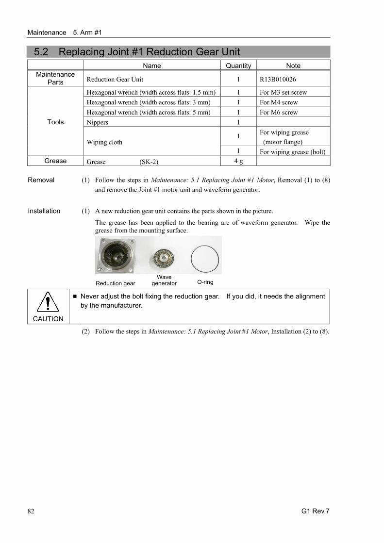
Maintenance 5. Arm #1
82 G1 Rev.7
5.2 Replacing Joint #1 Reduction Gear Unit Name Quantity Note
Maintenance Parts Reduction Gear Unit 1 R13B010026
Tools
Hexagonal wrench (width across flats: 1.5 mm) 1 For M3 set screw Hexagonal wrench (width across flats: 3 mm) 1 For M4 screw Hexagonal wrench (width across flats: 5 mm) 1 For M6 screw Nippers 1
Wiping cloth 1 For wiping grease
(motor flange) 1 For wiping grease (bolt)
Grease Grease (SK-2) 4 g Removal (1) Follow the steps in Maintenance: 5.1 Replacing Joint #1 Motor, Removal (1) to (8)
and remove the Joint #1 motor unit and waveform generator.
Installation (1) A new reduction gear unit contains the parts shown in the picture.
The grease has been applied to the bearing are of waveform generator. Wipe the grease from the mounting surface.
Reduction gear O-ring Wave
generator
CAUTION
■ Never adjust the bolt fixing the reduction gear. If you did, it needs the alignment by the manufacturer.
(2) Follow the steps in Maintenance: 5.1 Replacing Joint #1 Motor, Installation (2) to (8).

Maintenance 6. Arm #2
G1 Rev.7 83
6. Arm #2
WARNING
■ Do not insert or pull out the motor connectors while the power to the robot system is turned ON. Inserting or pulling out the motor connectors with the power ON is extremely hazardous and may result in serious bodily injury as the Manipulator may move abnormally, and also may result in electric shock and/or malfunction of the robot system.
■ To shut off power to the robot system, pull out the power plug from the power source. Be sure to connect the AC power cable to a power receptacle. DO NOT connect it directly to a factory power source.
■ Before performing any replacement procedure, turn OFF the Controller and related equipment, and then pull out the power plug from the power source. Performing any replacement procedure with the power ON is extremely hazardous and may result in electric shock and/or malfunction of the robot system.
CAUTION
■ Be careful not to apply excessive shock to the motor shaft when replacing the motors. The shock may shorten the life cycle of the motors and encoder and/or damage them.
■ Never disassemble the motor and encoder. A disassembled motor and encoder will cause a positional gap and cannot be used again.
After parts have been replaced (motors, reduction gear units, brakes, timing belts, ball screw spline unit, etc.), the Manipulator cannot operate properly because a mismatch exists between the origin stored in each motor and its corresponding origin stored in the Controller. After replacing the parts, it is necessary to match these origins.
The process of aligning the two origins is called “Calibration”.
Refer to Maintenance: 13. Calibration to perform the calibration.
Joint #2 reduction gear
Joint #2 motor
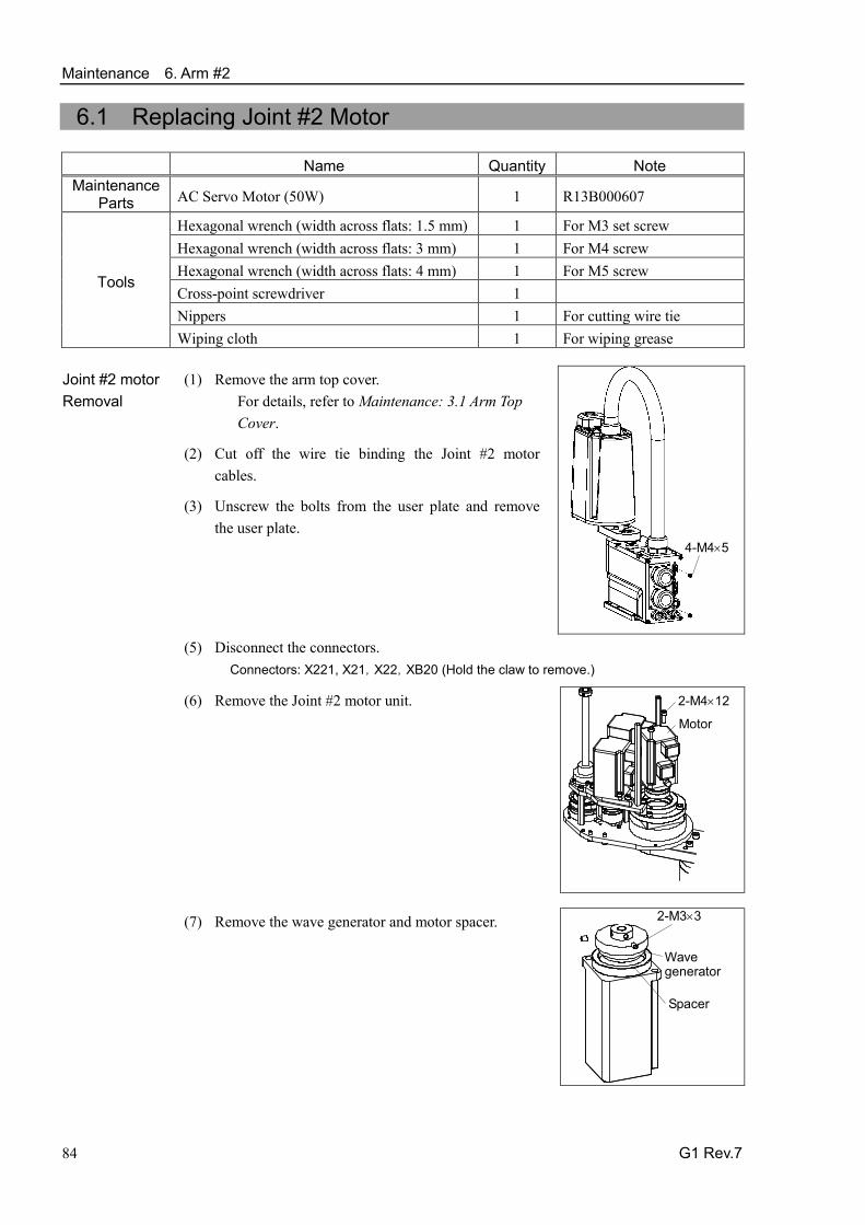
Maintenance 6. Arm #2
84 G1 Rev.7
6.1 Replacing Joint #2 Motor
Name Quantity Note Maintenance
Parts AC Servo Motor (50W) 1 R13B000607
Tools
Hexagonal wrench (width across flats: 1.5 mm) 1 For M3 set screw Hexagonal wrench (width across flats: 3 mm) 1 For M4 screw Hexagonal wrench (width across flats: 4 mm) 1 For M5 screw Cross-point screwdriver 1 Nippers 1 For cutting wire tie Wiping cloth 1 For wiping grease
Joint #2 motor Removal
(1) Remove the arm top cover. For details, refer to Maintenance: 3.1 Arm Top Cover.
4-M4×5
(2) Cut off the wire tie binding the Joint #2 motor cables.
(3) Unscrew the bolts from the user plate and remove the user plate.
(5) Disconnect the connectors. Connectors: X221, X21,X22,XB20 (Hold the claw to remove.)
(6) Remove the Joint #2 motor unit. 2-M4×12
Motor
(7) Remove the wave generator and motor spacer. 2-M3×3
Wave generator
Spacer

Maintenance 6. Arm #2
G1 Rev.7 85
Joint #2 motor Installation
(1) Mount the motor spacer and wave generator on the Joint #2 motor.
Be sure to fit the edge of the waveform generator to the edge of the motor shaft. Tighten one of the set screws on the flat face of the motor shaft until the screw just touches the surface. Insert a bushing into the other set screw hole to prevent damage to the motor shaft. Then, tighten both set screws.
2-M3×3
Wave generator
Spacer
CAUTION
■ See the figures above for the orientation of the waveform generator. Be sure to install the waveform generator properly. Improper installation of the waveform generator will result in improper function of the Manipulator.
(2) Mount the Joint #2 motor unit on Arm #2.
If it is difficult to mount the motor, push it while moving Arm #2 slowly by hand.
2-M4×12
Motor
(3) Connect the connectors. Connectors: X221, X21, X22, XB20
(4) Mount the user plate. Screws: 4- M4×5
(5) Put the wire tie cut in the removal step (4) to the original position.
Do not allow unnecessary strain on the cables.
(6) Mount the arm top cover. For details, refer to Maintenance: 3.1 Arm Top Cover.
(7) Perform the calibration of Joint #2. For details refer to Maintenance: 13. Calibration.

Maintenance 6. Arm #2
86 G1 Rev.7
6.2 Replacing Joint #2 Reduction Gear Unit
Name Quantity Note Maintenance
Parts Reduction Gear Unit 1 R13B010027
Tools
Hexagonal wrench (width across flats: 1.5 mm) 1 For M3 set screw Hexagonal wrench (width across flats: 2.5 mm) 1 For M3 screw Hexagonal wrench (width across flats: 3 mm) 1 For M4 screw Hexagonal wrench (width across flats: 4 mm) 1 For M5 screw Cross-point screwdriver 1 Nippers 1
Wiping cloth (Motor flange) 1 For wiping grease (Bolt) 1 For wiping grease
Grease Grease (SK-2) 4 g

Maintenance 6. Arm #2
G1 Rev.7 87
Joint #2 reduction gear unit Removal
(1) Follow the steps in Maintenance: 6.1 Replacing Joint #2 Motor, removal (1) to (7).
Remove the waveform generator from the Joint #2 motor.
(2) Remove the Arm #2 spacer.
2-M4×25
Spacer
(3) Loosen the screw fixing the Joint #2 reduction gear unit and loosely secure.
2-M4×40
Arm #2 Reduction gear unit
2-M5×40
(4) Remove the Arm #2 unit.
6-M4×12
Arm #2 unit
(5) Remove the screw secured loosely in the step(3) and also remove the Joint #2 motor flange, reduction gear, and Joint #2 spacer.
Hold the Joint #2 spacer upward and pull it out sideways.
Joint #2 motor flange
Joint #2 spacer
Joint #2 reduction gear

Maintenance 6. Arm #2
88 G1 Rev.7
Joint #2 reduction gear unit Installation
(1) A new reduction gear unit contains the parts shown in the picture.
The grease has been applied to the bearing are of waveform generator. Wipe the grease from the mounting surface.
Reduction gear O-ring Wave
generator (2) Put the O-ring into the groove in the reduction gear top surface.
(3) Mount the Joint #2 motor flange, reduction gear, and Joint #2 spacer.
Hold the Joint #2 spacer and mount by reverse procedure to remove it.
Joint #2 motor flange
Joint #2 spacer
Joint #2 reduction gear
(4) Loosely secure the Joint #2 reduction gear unit.
Make sure the O-ring between the reduction gear and motor flange has not moved and secure the unit loosely.
2-M4×40
Arm #2 Reduction gear unit
2-M5×40 (5) Mount the Arm #2 unit.
6-M4×12
Arm #2 unit
(6) Tighten the screw secured loosely in the step
(4).

Maintenance 6. Arm #2
G1 Rev.7 89
(7) Mount the Arm #2 spacer.
2-M4×25
Spacer
(8) Follow the steps in Maintenance: 6.1 Replacing Joint #2 Motor, installation step (1) to (7).

Maintenance 7. Arm #3
90 G1 Rev.7
7. Arm #3
WARNING
■ Do not insert or pull out the motor connectors while the power to the robot system is turned ON. Inserting or pulling out the motor connectors with the power ON is extremely hazardous and may result in serious bodily injury as the Manipulator may move abnormally, and also may result in electric shock and/or malfunction of the robot system.
■ To shut off power to the robot system, pull out the power plug from the power source. Be sure to connect the AC power cable to a power receptacle. DO NOT connect it directly to a factory power source.
■ Before performing any replacement procedure, turn OFF the Controller and related equipment, and then pull out the power plug from the power source. Performing any replacement procedure with the power ON is extremely hazardous and may result in electric shock and/or malfunction of the robot system.
CAUTION
■ Be careful not to apply excessive shock to the motor shaft when replacing the motors. The shock may shorten the life cycle of the motors and encoder and/or damage them.
■ Never disassemble the motor and encoder. A disassembled motor and encoder will cause a positional gap and cannot be used again.
After parts have been replaced (motors, reduction gear units, brakes, timing belts, ball screw spline unit, etc.), the Manipulator cannot operate properly because a mismatch exists between the origin stored in each motor and its corresponding origin stored in the Controller. After replacing the parts, it is necessary to match these origins.
The process of aligning the two origins is called “Calibration”.
Refer to Maintenance: 13. Calibration to perform the calibration.
Joint #3 motor
Z belt
Joint #3 brake

Maintenance 7. Arm #3
G1 Rev.7 91
7.1 Replacing Joint #3 Motor
Name Quantity Note Maintenance
parts AC Servo Motor (50W) 1
Tools
Hexagonal wrench (width across flats: 1.5 mm) 1 For M3 set screw Hexagonal wrench (width across flats: 2 mm) 1 For M4 set screw Hexagonal wrench (width across flats: 3 mm) 1 For M4 screw Hexagonal wrench (width across flats: 4 mm) 1 For M5 screw Torque wrench 1 Nippers 1 For cutting wire tie Force gauge 1 Belt tension 30 N Suitable cord (Length about 800 mm) 1 For belt tension
Material Wire tie 2
A brake is mounted on the Joint #3 motor to prevent the shaft from moving down due to the weight of the end effector while the power to the Controller is OFF or while the motor is in OFF status (MOTOR OFF).
Note that the brake will not work during the replacement procedure. Move the shaft down to its lower limit before starting the replacement procedure by following the removal steps from (1) to (3).

Maintenance 7. Arm #3
92 G1 Rev.7
Joint #3 motor Removal
(1) Turn ON the Controller.
(2) Push down the shaft to its lower limit while pressing the brake release switch. Be sure to keep enough space and prevent the end effector hitting any peripheral equipment.
When the brake release switch is pressed, the brake of the Joint #3 is released.
Be careful of the shaft falling while the brake release switch is being pressed because the shaft may be lowered by the weight of an end effector.
(3) Turn OFF the Controller.
(4) Remove the arm top cover. For details, refer to Maintenance: 3.1 Arm Top Cover.
(5) Cut off the wire tie used for binding the motor cables to the Joint #3 motor.
(6) Disconnect the connectors. Connectors X231, X31, X32, X33, XB30 (Hold the claw to remove.)
(7) Remove the user plate. For details, refer to Maintenance 3.4 User Plate.
(8) Loosen the Z belt.
Loosen two bolts on the Joint #3 motor unit. Slide the Joint #3 motor unit toward the arm end.
2-M4×10
Z belt Z1 pulley
Motor
(9) Remove the Joint #3 motor unit from Arm #2.
Unscrew the bolts securing the Joint #3 motor unit. Remove the Z1 pulley from the Z belt. Pull the Joint #3 motor unit upward to remove.
(10) Remove the Joint #3 motor from the Joint #3 motor unit.
2-M4×10
Motor Pulley
Remove the brake hub and pulley from the Joint #3 motor.
Loosen the screw of pulley and slide the pulley toward the motor and then, loosen the screw of brake hub.
There is a brass bushing in one of the set screw holes. Be careful not to lose it.

Maintenance 7. Arm #3
G1 Rev.7 93
Joint #3 motor Installation
(1) Mount the brake hub and pulley to the new motor shaft.
Make sure to put a space of 1.5 mm between the edges of the brake hub and motor shaft.
Brake hub After the brake hub is mounted, press the pulley lightly to the brake hub and secure.
Both of the brake hub and pulley, tighten one of the set screws on the flat face of the motor shaft until the screw just touches the surface.
Insert a bushing into the other set screw hole to prevent damage to the motor shaft. Then, tighten both set screws.
(2) Mount the Z plate on the Joint #3 motor.
Align the brake disk with the hub and join them.
If the brake disk position is not right, turn ON the controller power supply, attach the connector X32, release the brake by pressing the brake release switch, and move the hole to the center by hand.
2-M4×10
Z plate
Disk (3) Place the Joint #3 motor unit in the arm.
2-M4×12
Motor unit
(4) Place the Z belt around the Z1 pulley and the Z2
pulley so that the gear grooves of the belt are fit into those of the pulleys completely.
Z belt
(5) Loosely secure the Joint #3 motor unit to Arm #2.
Make sure the motor unit can be moved by hand, and it will not tilt when pulled. If the unit is secured too loose or too tight, the belt will not have the proper tension.
NOTE
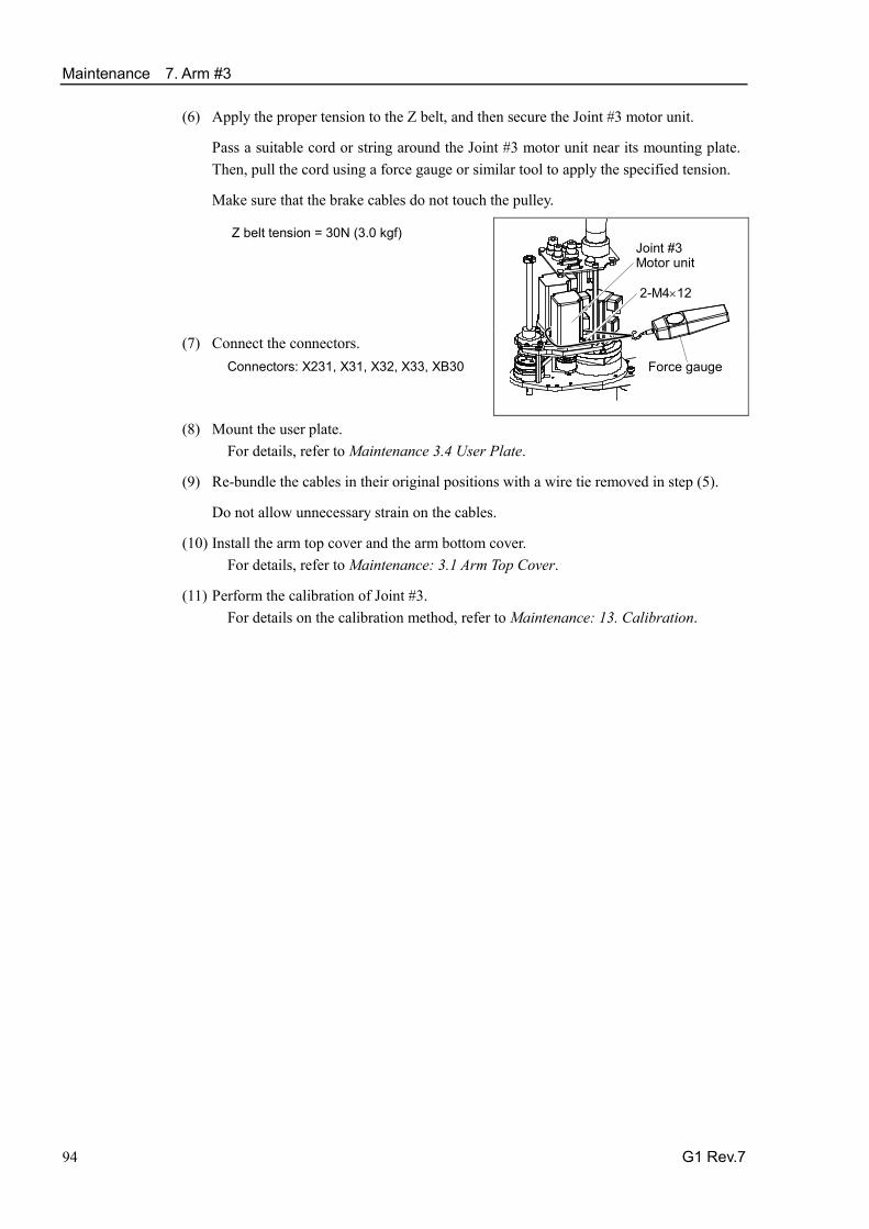
Maintenance 7. Arm #3
94 G1 Rev.7
(6) Apply the proper tension to the Z belt, and then secure the Joint #3 motor unit.
Pass a suitable cord or string around the Joint #3 motor unit near its mounting plate. Then, pull the cord using a force gauge or similar tool to apply the specified tension.
Make sure that the brake cables do not touch the pulley.
Z belt tension = 30N (3.0 kgf)
2-M4×12
Force gauge
Joint #3 Motor unit
(7) Connect the connectors. Connectors: X231, X31, X32, X33, XB30
(8) Mount the user plate.
For details, refer to Maintenance 3.4 User Plate.
(9) Re-bundle the cables in their original positions with a wire tie removed in step (5).
Do not allow unnecessary strain on the cables.
(10) Install the arm top cover and the arm bottom cover. For details, refer to Maintenance: 3.1 Arm Top Cover.
(11) Perform the calibration of Joint #3. For details on the calibration method, refer to Maintenance: 13. Calibration.

Maintenance 7. Arm #3
G1 Rev.7 95
7.2 Replacing the Timing Belt
Name Quantity Note Maintenance
part Z belt 1 R13B030226
Tools
Hexagonal wrench (width across flats: 2.5 mm) 1 For M3 screw Hexagonal wrench (width across flats: 3 mm) 1 For M4 screw Nippers 1 For cutting wire tie Force gauge 1 Belt tension 30 N (3.0 kgf) Suitable cord (Length about 800 mm) 1 For belt tension
Material Wire tie 2
A brake is mounted on the Joint #3 motor to prevent the shaft from moving down due to the weight of the end effector while the power to the Controller is OFF or while the motor is in OFF status (MOTOR OFF).
Note that the brake will not work during the replacement procedure. Move the shaft down to its lower limit before starting the replacement procedure by following the removal steps from (1) to (3).
Z belt Removal
(1) Turn ON the Controller.
(2) Push down the shaft to its lower limit while pressing the brake release switch. Be sure to keep enough space and prevent the end effector hitting any peripheral equipment.
When the brake release switch is pressed, the brake of the Joint #3 is released.
Be careful of the shaft falling while the brake release switch is being pressed because the shaft may be lowered by the weight of an end effector.
(3) Turn OFF the Controller.
2-M4×12
(4) Loosen the bolt securing the Joint #3 motor unit.
(5) Remove the belt from the Z1 pulley and Z2 pulley.
(6) Remove the Z belt.
Remove the bolts securing the ball screw nut and hold the ball screw nut up to pull out the Z belt upward from the shaft.
4-M4×30
Z belt
Maintenance 7. Arm #3
96 G1 Rev.7
Z belt Installation
(1) Pass a new Z belt through the shaft from above, and then place it under the ball screw nut.
4-M4×30
Z belt
(2) Loosely secure the ball screw nut to Arm #2.
After moving the shaft up and down several times, secure the ball screw nut to Arm #2.
(3) Place the belt around the Z1 pulley and the Z2 pulley so that the gear grooves of the belt are fit into those of the pulleys completely.
(4) Apply the proper tension to the Z belt, and then secure the Joint #3 motor unit.
Z belt tension = 30 N (3.0 kgf)
2-M4×12
Force gauge
Joint #3 Motor unit
(5) Perform the calibration of Joint #3.
For details, refer to Maintenance: 13. Calibration.

Maintenance 7. Arm #3
G1 Rev.7 97
7.3 Replacing the Brake
Name Quantity Note Maintenance
parts Solenoid brake 1
Tools
Hexagonal wrench (width across flats: 1.5 mm) 1 For M3 set screw Hexagonal wrench (width across flats: 2.5 mm) 1 For M3 screw Hexagonal wrench (width across flats: 3 mm) 1 For M4 screw Hexagonal wrench (width across flats: 4 mm) 1 For M5 screw Nippers 1 For cutting wire tie Force gauge 1 Belt tension 30 N (3.0 kgf) Suitable cord (Length about 800 mm) 1 For belt tension
Material Wire tie 3
A brake is mounted on the Joint #3 motor to prevent the shaft from moving down due to the weight of the end effector while the power to the Controller is OFF or while the motor is in OFF status (MOTOR OFF).
Note that the brake will not work during the replacement procedure. Move the shaft down to its lower limit before starting the replacement procedure by following the removal steps from (1) to (3).
Joint #3 brake Removal
(1) Turn ON the Controller.
(2) Push down the shaft to its lower limit while pressing the brake release switch. Be sure to keep enough space and prevent the end effector hitting any peripheral equipment.
When the brake release switch is pressed, the brake of the Joint #3 is released.
Be careful of the shaft falling while the brake release switch is being pressed because the shaft may be lowered by the weight of an end effector.
(3) Turn OFF the Controller.
(4) Refer to Maintenance 7.1 Replacing Joint #3 Motor, Removal step (4) to (11) and remove the brake hub from the Joint #3 motor.
(5) Remove the brake from the brake plate.
2-M2.6×6
Joint #3 brake Installation
(1) Mount the brake on the brake plate.
(2) Refer to Maintenance 7.1 Replacing Joint #3 Motor, Installation step (1) to (11) and mount the Joint #2 motor unit to Arm #2 after the brake hub is replaced.
(3) Perform the calibration of Joint #3. For details, refer to Maintenance: 13. Calibration.

Maintenance 8. Arm #4
98 G1 Rev.7
8. Arm #4
WARNING
■ Do not insert or pull out the motor connectors while the power to the robot system is turned ON. Inserting or pulling out the motor connectors with the power ON is extremely hazardous and may result in serious bodily injury as the Manipulator may move abnormally, and also may result in electric shock and/or malfunction of the robot system.
■ To shut off power to the robot system, pull out the power plug from the power source. Be sure to connect the AC power cable to a power receptacle. DO NOT connect it directly to a factory power source.
■ Before performing any replacement procedure, turn OFF the Controller and related equipment, and then pull out the power plug from the power source. Performing any replacement procedure with the power ON is extremely hazardous and may result in electric shock and/or malfunction of the robot system.
CAUTION
■ Be careful not to apply excessive shock to the motor shaft when replacing the motors. The shock may shorten the life cycle of the motors and encoder and/or damage them.
■ Never disassemble the motor and encoder. A disassembled motor and encoder will cause a positional gap and cannot be used again.
After parts have been replaced (motors, reduction gear units, brakes, timing belts, ball screw spline unit, etc.), the Manipulator cannot operate properly because a mismatch exists between the origin stored in each motor and its corresponding origin stored in the Controller. After replacing the parts, it is necessary to match these origins.
The process of aligning the two origins is called “Calibration”.
Refer to Maintenance: 13. Calibration to perform the calibration.
Joint #4 motor
U belt
Maintenance 8. Arm #4
G1 Rev.7 99
8.1 Replacing Joint #4 Motor
Name Quantity Note
Maintenance parts AC Servo Motor (50 W) 1 R13B000619
Tools
Hexagonal wrench (width across flats: 2 mm) 1 For M4 set screw Hexagonal wrench (width across flats: 2.5 mm) 1 For M3 screw Hexagonal wrench (width across flats: 3 mm) 1 For M4 screw Cross-point screwdriver 1 Nippers 1 For cutting wire tie Force gauge 1 Belt tension 30 N (3.0 kgf) Suitable cord (Length about 800 mm) 1 For belt tension
A brake is mounted on the Joint #3 motor to prevent the shaft from moving down due to the weight of the end effector while the power to the Controller is OFF or while the motor is in OFF status (MOTOR OFF).
Note that the brake will not work during the replacement procedure. Move the shaft down to its lower limit before starting the replacement procedure by following the removal steps from (1) to (3).
Maintenance 8. Arm #4
100 G1 Rev.7
Joint #4 motor Removal
(1) Turn ON the Controller.
(2) Push down the shaft to its lower limit while pressing the brake release switch. Be sure to keep enough space and prevent the end effector hitting any peripheral equipment.
When the brake release switch is pressed, the brake of the Joint #3 is released.
Be careful of the shaft falling while the brake release switch is being pressed because the shaft may be lowered by the weight of an end effector.
(3) Turn OFF the Controller.
(4) Remove the arm top cover and the arm bottom cover. For details, refer to Maintenance: 3.1 Arm Top Cover.
(5) Cut off the wire tie used for binding the motor cables to the Joint #4 motor.
(6) Disconnect the connectors. Connectors: X241, X41, X64 (Hold the claw to remove.)
(7) Remove the user plate. For details, refer to Maintenance 3.4 User Plate.
(8) Remove the Joint #4 motor unit from Arm #2.
Unscrew the bolts securing the Joint #4 motor to the motor plate. Remove the U1 belt from the pulley. Pull the motor unit upward to remove.
2-M4×12
U1 belt
Pulley
Motor
(9) Remove the motor from the Joint #4 motor
housing.
2-M4×12
Motor housing
Motor
(10) Remove the pulley from the Joint #4 motor.
There is a brass bushing in one of the set screw holes. Be careful not to lose it.
2-M4×5
Pulley
Motor

Maintenance 8. Arm #4
G1 Rev.7 101
Joint #4 motor Installation
(1) Mount the pulley to the new Joint #4 motor.
Be sure to fit the edge of the pulley to the edge of the motor shaft.
Tighten one of the set screws on the flat face of the motor shaft until the screw just touches the surface.
Insert a bushing into the other set screw hole to prevent damage to the motor shaft. Then, tighten both set screws.
(2) Mount the housing to the Joint #4 motor.
2-M4×12
Motor housing
Motor
(3) Place the Joint #4 motor unit in the arm so that
the motor cable faces toward the back of the arm.
2-M4×12
U1 belt
Pulley
Motor
(4) Place the belt around the U1 pulley and the U2 pulley so that the gear grooves of the belt are fit into those of the pulleys completely.
(5) Loosely secure the Joint #4 motor unit to Arm
#2.
Make sure the motor unit can be moved by hand, and it will not tilt when pulled. If the unit is secured too loose or too tight, the belt will not have the proper tension.
U1 pulley U2 pulley
(6) Apply the proper tension to the U1 belt, and
then secure the Joint #4 motor unit.
To do so, pass a suitable cord or string around the Joint #4 motor unit near its mounting plate. Then, pull the cord using a force gauge or similar tool to apply the specified tension.
U belt tension = 30N (3.0 kgf)
4-M4×12 + washer
Force gauge
Joint #4 Motor unit
NOTE

Maintenance 8. Arm #4
102 G1 Rev.7
(7) Connect the connectors.
Connectors: X241, X41, X64
(8) Mount the user plate. For details, refer to Maintenance 3.4 User Plate.
(9) Re-bundle the cables in their original positions with a wire tie removed in step (5).
Do not allow unnecessary strain on the cables.
(10) Install the arm top cover and the arm bottom cover. For details, refer to Maintenance: 3.1 Arm Top Cover.
(11) Perform the calibration of Joint #4. For details on the calibration method, refer to Maintenance: 13. Calibration.

Maintenance 8. Arm #4
G1 Rev.7 103
8.2 Replacing the Timing Belt
Name Quantity Note
Maintenance parts
U1 belt 1 R13B030227 Z belt 1 R13B030226
Tools
Hexagonal wrench (width across flats: 2.5 mm) 1 For M3 screw Hexagonal wrench (width across flats: 3 mm) 1 For M4 screw Cross-point screwdriver 1 Nippers 1 For cutting wire tie Force gauge 1 Belt tension: 30 N (3.0 kgf) Suitable cord (Length about 800 mm) 1 For belt tension
A brake is mounted on the Joint #3 motor to prevent the shaft from moving down due to the weight of the end effector while the power to the Controller is OFF or while the motor is in OFF status (MOTOR OFF).
Note that the brake will not work during the replacement procedure. Move the shaft down to its lower limit before starting the replacement procedure by following the removal steps from (1) to (3).
U belt Removal
(1) Turn ON the Controller.
(2) Push down the shaft to its lower limit while pressing the brake release switch. Be sure to keep enough space and prevent the end effector hitting any peripheral equipment.
When the brake release switch is pressed, the brake of the Joint #3 is released.
Be careful of the shaft falling while the brake release switch is being pressed because the shaft may be lowered by the weight of an end effector.
(3) Turn OFF the Controller.
2-M4×12
(4) Remove the arm top cover and the arm bottom cover. For details, refer to Maintenance: 3.1 Arm Top Cover.
(5) Loosen the bolts securing the Joint #4 motor unit.
(6) Remove the U belt from the U1 pulley.
(7) Remove the Z belt. For details, refer to Maintenance 7.2 Replacing the Timing Belt, Z belt Removal step (4) to (6).
(8) Remove the U belt.
Hold the ball screw nut up and pull out the U belt upward from the shaft.
4-M3×10

Maintenance 8. Arm #4
104 G1 Rev.7
U belt Installation
(1) Pass a new U belt through the shaft from above, and then pass a new Z belt too. Place them under the ball screw nut.
(2) Loosely secure the ball screw nut to Arm #2.
After moving the shaft up and down several times, secure the ball screw nut to Arm #2.
(3) Place the U belt around the U1 pulley and the U2 pulley so that the gear grooves of the belt are fit into those of the pulleys completely..
(4) Place the Z belt around the Z1 pulley and the Z2 pulley so that the gear grooves of the belt are fit into those of the pulleys completely.
(5) Loosely secure the Joint #3 motor unit and Joint #4 motor unit to Arm #2.
Make sure the gear grooves of the belt are fit into those of the pulleys completely.
Loosely secure the units to Arm #2 so that the motor unit can be moved by hand, and it will not tilt when pulled. If the units are secured too loose or too tight, the belt will not have the proper tension.
(6) Apply the proper tension to the Z belt, and then secure the Joint #3 motor unit.
To do so, pass a suitable cord or string around the Joint #3 motor unit near its mounting plate. Then, pull the cord using a force gauge or similar tool to apply the specified tension.
Z belt tension = 30N (3.0 kgf)
2-M4×12
Force gauge
Joint #3 motor unit
(7) Apply the proper tension to the U belt, and
then secure the Joint #4 motor unit.
To do so, pass a suitable cord or string around the Joint #4 motor unit near its mounting plate. Then, pull the cord using a force gauge or similar tool to apply the specified tension.
U belt tension = 30N (3.0 kgf)
4-M4×12 + washer
Force gauge
Joint #4 Motor unit
(8) Install the arm top cover and the arm bottom cover.
For details, refer to Maintenance: 3.1 Arm Top Cover.
(9) Perform the calibration of Joints #3 and #4. For details on the calibration method, refer to Maintenance: 13. Calibration.
NOTE

Maintenance 9. Bellows
G1 Rev.7 105
9. Bellows Two bellows make a set as maintenance parts. There is no difference between the upper bellows and lower bellows. A large amount of dust is emitted when replacing the bellows. Take the Manipulator to an outer room such as the room in front of the clean room’s entrance, or take the necessary countermeasures to prevent dust emission before removing the bellows.
Name Quantity Note
Maintenance parts
Bellows 1 For each manipulator model (Refer to Maintenance 14. Maintenance Parts List.)
Tools Cross-point screwdriver 1 Gasket Liquid gasket 1206C 1
NOTE

Maintenance 9. Bellows
106 G1 Rev.7
9.1 Replacing the Bellows (4-axis spec) Bellows Removal (4-axis spec)
(1) Stop motor excitation. (MOTOR OFF)
(2) Remove the end effecter.
(3) Remove the wires and tubes from the end effector.
(4) Turn OFF the controller power.
(5) Loosen the two clamp bands on bellows.
Clamp band Bearing case
(6) Remove the bearing case.
(7) Loosen the set screw of fixing ring.
Remove the fixing ring and bearing.
Bearing Fixing ring
(8) Remove the bellows and the plate securing the bellows.
Bellows plate 4-M3×6
(9) Pull out the bellows from the bellows plate.

Maintenance 9. Bellows
G1 Rev.7 107
Bellows Installation (4-axis spec)
(1) Press the brake release switch and move the shaft to the point 10 mm ~ 20 mm down from the upper limit.
(2) Insert the flat part of bellows into the bellows plate.
(3) Mount the bellows and bellows plate on the arm.
Bellows plate 4-M3×6
(4) Wipe off the old liquid gasket from the upper limit
mechanical stop, and then apply new liquid gasket to it lightly.
Apply the liquid gasket to the whole bottom surface of the mechanical stop.
Liquid gasket (5) Insert the bearing and fixing ring from below the
shaft and secure the bearing fixing ring by pressing it upward.
When securing the fixing ring, make sure the set screw does not touch the spline groove.
2-M13×3
Liquid gasket Bearing
Bearing case
Fixing ring
(6) Wipe off the old liquid gasket from the inside surface of bearing case, and then apply new liquid gasket to it lightly.
Insert it into the shaft from below.
Apply the liquid gasket to the whole inside surface of the bearing case.
(7) Insert the bellows lower part into the bearing case and secure with the clamp band.

Maintenance 9. Bellows
108 G1 Rev.7
9.2 Replacing the Bellows (3-axis spec) Bellows Removal (3-axis spec)
(1) Stop motor excitation. (MOTOR OFF)
(2) Remove the end effector.
(3) Detach the wires/tubes from the end effector.
(4) Loosen the two clamp bands on each bellows.
Clamp band screw on upper bellows
Clamp band screw on lower bellows
Bellows plate 4-M3×8
(5) Remove the plate securing the lower bellows.
(6) Pull out the lower bellows, bellows plate, and clamp band from the shaft.
(7) Pull out the lower bellows from the bellows plate.
(8) Press the brake release switch and move the shaft to its lower limit.
(9) Remove the arm top cover. For details, refer to Maintenance: 3. Covers.
(10) Remove the plate securing the upper bellows.
Remove the set screw from inside of the arm top cover while pressing the nut.
Bellows plate
4-M3×8
4-M3 nut
(11) Pull out the upper bellows from the bellows plate.

Maintenance 9. Bellows
G1 Rev.7 109
Bellows Installation (3-axis spec)
(1) Pass the flat part of the upper bellows through the bellows plate and put the bellows and arm top cover between two bellows plate and secure them.
Press the nut and remove the set screw from inside of the arm top cover.
Bellows plate
4-M3×8
4-M3 nut
(2) Mount the arm top cover. For details, refer to Maintenance: 3. Covers.
(3) Pass the flat part of the lower bellows through the bellows plate and put the bellows between the bellows plate and Arm #2 bottom surface and secure it.
Clamp band screw on upper bellows
Clamp band screw on lower bellows
Bellows plate 4-M3×8
(4) Secure the cylinder side of two bellows with clamp bands.
To attach the upper bellows, move the shaft to its lower limit.
To attach the lower bellows, move the shaft to its upper limit.
Press the brake release switch and move the shaft up/down.

Maintenance 10. Ball Screw Spline Unit
110 G1 Rev.7
10. Ball Screw Spline Unit
WARNING
■ Do not insert or pull out the motor connectors while the power to the robot system is turned ON. Inserting or pulling out the motor connectors with the power ON is extremely hazardous and may result in serious bodily injury as the Manipulator may move abnormally, and also may result in electric shock and/or malfunction of the robot system.
■ To shut off power to the robot system, pull out the power plug from the power source. Be sure to connect the AC power cable to a power receptacle. DO NOT connect it directly to a factory power source.
■ Before performing any replacement procedure, turn OFF the Controller and related equipment, and then pull out the power plug from the power source. Performing any replacement procedure with the power ON is extremely hazardous and may result in electric shock and/or malfunction of the robot system. After parts have been replaced (motors, reduction gear units, brakes, timing belts, ball screw spline unit, etc.), the Manipulator cannot operate properly because a mismatch exists between the origin stored in each motor and its corresponding origin stored in the Controller. After replacing the parts, it is necessary to match these origins.
The process of aligning the two origins is called “Calibration”.
Refer to Maintenance: 13. Calibration to perform the calibration.
10.1 Greasing the Ball Screw Spline Unit
Name Quantity Note
Grease For Ball Screw Spline Unit (AFB grease) Proper
quantity
Tools Wiping cloth 1 For wiping grease (Spline shaft) Cross-point screwdriver 1
The brake release switch is applied to Joint #3. When the brake release switch is pressed, the Joint #3 brake is released. Be careful of the shaft falling while the brake release switch is being pressed because the shaft may be lowered by the weight of the end effector.
NOTE
NOTE

Maintenance 10. Ball Screw Spline Unit
G1 Rev.7 111
10.1.1 Standard-model (S type) Cover the surrounding area such as the end effector and peripheral equipment in case the grease drips.
(1) Turn ON the controller power. Stop motor excitation. (MOTOR OFF)
(2) Move the arm to a position where Joint #3 can be moved in full stroke.
(3) Move the shaft to its upper limit manually while pressing the brake release switch.
Brake release switch
(4) Turn OFF the controller power.
(5) Remove the arm top cover. For details, refer to Maintenance: 3. Covers.
(6) Wipe off the old grease from the upper part of the shaft, and then apply new grease to it.
When applying the new grease, directly fill the grooves on the shaft by hand. Wipe off excess grease from the shaft.
(7) Mount the arm top cover. For details, refer to Maintenance: 3. Covers.
(8) Turn ON the controller power.
(9) Move the shaft to its lower limit while pressing the brake release switch.
(10) Wipe off the old grease from the lower part of the shaft, and then apply new grease to it.
When applying the new grease, directly fill the grooves on the shaft by hand. Wipe off excess grease from the shaft.
(11) Move the shaft up and down several times while pressing the brake release switch to smooth out the grease on the shaft. Wipe off excess grease from the shaft.
When wiping off the excess grease from the upper part of shaft, turn OFF the controller power supply and remove the arm top cover. For details, refer to Maintenance: 3. Covers.

Maintenance 10. Ball Screw Spline Unit
112 G1 Rev.7
10.1.2 Cleanroom-model (C type) Cover the surrounding area such as the end effector and peripheral equipment in case the grease drips.
(1) Turn ON the controller power. Stop motor excitation. (MOTOR OFF)
(2) Move the arm to a position where Joint #3 can be moved in full stroke.
(3) Move the shaft to its upper limit manually while pressing the brake release switch.
Brake release switch
Clamp band screw on lower bellows
(4) Turn OFF the controller power.
(5) Remove the arm top cover. For details, refer to Maintenance: 3. Covers.
(6) Wipe off the old grease from the upper part of the shaft, and then apply new grease to it.
Directly fill the grooves on the shaft inside the bellows with grease by hand. Wipe off excess grease from the shaft.
(7) Mount the arm top cover. For details, refer to Maintenance: 3. Covers.
(8) Turn ON the controller power.
(9) Move the shaft to its lower limit while pressing the brake release switch.
(10) Loosen the clamp band under the bellows, and then lift the bellows.
For the 3-axis spec, remove the set screw of the plate attached to the lower bellows and lower the bellows.
(11) Wipe off the old grease from the lower part of the shaft, and then apply new grease to it.
Directly fill the grooves on the shaft inside the bellows with grease by hand. Wipe off excess grease from the shaft.
(12) Move the shaft up and down several times while pressing the brake release switch to smooth out the grease on the shaft. Wipe off excess grease from the shaft.
When wiping off the excess grease from the upper part of shaft, turn OFF the controller power supply and remove the arm top cover. For details, refer to Maintenance: 3.Covers.
(13) Put the lower part of bellows into the bearing case and secure with the clamp band.
For 3-axis spec, put the bellows into the Arm #2 bottom surface using the upper bellows plate and secure the bellows.
Maintenance 10. Ball Screw Spline Unit
G1 Rev.7 113
10.2 Replacing the Ball Screw Spline Unit A brake is mounted on the Joint #3 motor to prevent the shaft from moving down due to the weight of the end effector while the power to the Controller is OFF or while the motor is in OFF status (MOTOR OFF). Note that the brake will not work during the replacement procedure. Move the shaft down to its lower limit before starting the replacement procedure by following the removal steps from (1) to (3).
Name Quantity Note
Maintenance parts
Ball Screw Spline Unit 1 For each manipulator model (Refer to Maintenance: 14. Maintenance parts)
Grease For Ball Screw Spline Unit (AFB grease) Proper
quantity
Tools
Hexagonal wrench (width across flats: 2.5 mm)
1 For M3 screw
Torque wrench 1 Nippers 1 For cutting wire tie Force gauge 1 Belt tension 30 N (3.0 kgf) Suitable cord (Length about 1000 mm) 1 For belt tension
Wiping cloth 1 For wiping grease (Spline shaft)

Maintenance 10. Ball Screw Spline Unit
114 G1 Rev.7
10.2.1 Replacing the ball screw spline unit (4-axis spec)
Ball screw spline unit Removal (4-axis spec)
(1) Turn ON the controller power.
(2) Push down the shaft to its lower limit while pressing the brake release switch. Be sure to keep enough space and prevent the end effector hitting any peripheral equipment.
Be careful of the shaft falling while the brake release switch is being pressed because the shaft may be lowered by the weight of an end effector.
(3) Turn OFF the controller power.
(4) Detach the wires/tubes from the end effector, and remove the end effector.
(5) This step is only for Cleanroom-model.
Remove the bellows. For details, refer to Maintenance: 9. Bellows.
(6) Remove the arm top cover. For details, refer to Maintenance: 3. Covers.
(7) Remove the Joint #3 motor unit. For details, refer to Maintenance: 7.1 Replacing Joint #3 Motor.
(8) Remove the Joint #4 motor unit from Arm #2. For details, refer to Maintenance: 8.1 Replacing Joint #4 Motor.
(9) Remove the U belt and Z belt.
Remove the bolts securing the ball screw nut. Hold the ball screw nut up and remove the U belt and Z belt from the shaft by pulling them up.
4-M3×10
(10) Remove the nut mounting screws of the ball screw
spline shaft on the lower part of Arm #2.
4-M3×18
(11) Pull out the ball screw spline unit from Arm #2.
Remove the ball screw nut from the Arm #2 bottom plate and pull out the ball screw spline unit toward the cutout of the Arm #2 upper plate (front).
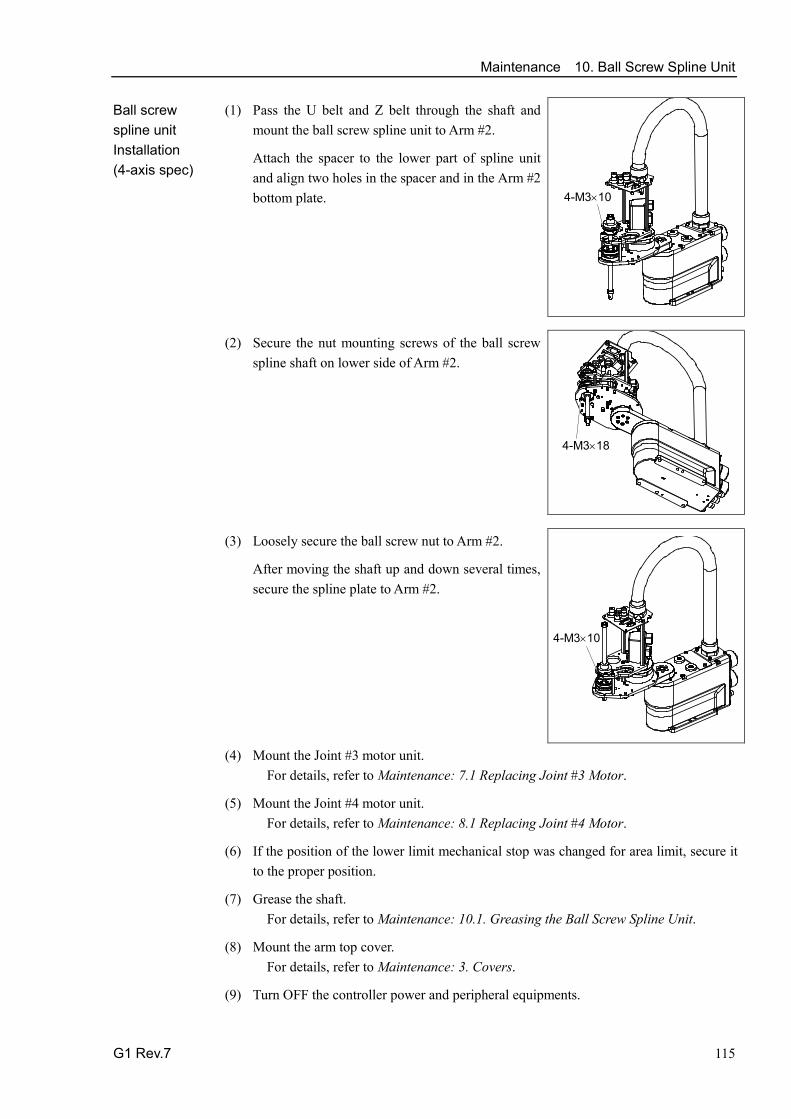
Maintenance 10. Ball Screw Spline Unit
G1 Rev.7 115
Ball screw spline unit Installation (4-axis spec)
(1) Pass the U belt and Z belt through the shaft and mount the ball screw spline unit to Arm #2.
Attach the spacer to the lower part of spline unit and align two holes in the spacer and in the Arm #2 bottom plate.
4-M3×10
(2) Secure the nut mounting screws of the ball screw
spline shaft on lower side of Arm #2.
4-M3×18
(3) Loosely secure the ball screw nut to Arm #2.
After moving the shaft up and down several times, secure the spline plate to Arm #2.
4-M3×10
(4) Mount the Joint #3 motor unit. For details, refer to Maintenance: 7.1 Replacing Joint #3 Motor.
(5) Mount the Joint #4 motor unit. For details, refer to Maintenance: 8.1 Replacing Joint #4 Motor.
(6) If the position of the lower limit mechanical stop was changed for area limit, secure it to the proper position.
(7) Grease the shaft. For details, refer to Maintenance: 10.1. Greasing the Ball Screw Spline Unit.
(8) Mount the arm top cover. For details, refer to Maintenance: 3. Covers.
(9) Turn OFF the controller power and peripheral equipments.

Maintenance 10. Ball Screw Spline Unit
116 G1 Rev.7
(10) This step is only for Cleanroom-model.
Install the bellows. For details, refer to Maintenance: 9. Bellows.
(11) Mount the end effector, and connect wires and tubes to the end effector.
(12) Perform the calibration for the Joints #3 and #4. For details, refer to Maintenance: 13. Calibration.

Maintenance 10. Ball Screw Spline Unit
G1 Rev.7 117
10.2.2 Replacing the ball screw spline unit (3-axis spec)
Ball screw spline unit Removal (3-axis spec)
(1) This step is only for Cleanroom-model.
Loosen the screw of bellows fixing ring and pull it out to the lower shaft. For details, refer to Maintenance: 9.2 Replacing the Bellows (3-axis spec), removal step (1) to (8).
(2) Remove the arm top cover and Joint #3 motor unit. For details, refer to Maintenance: 10.2.1 Replacing the ball screw spline unit (4-axis spec), removal step (1) to (7).
(3) Remove the screw securing the upper side of support shaft.
2-M3×12
Support guide
Shaft
Support shaft
(4) Loosen the screw securing the lower support guide to the shaft. Pull out the support guide and support shaft downward.
(5) Remove the screw securing the ball screw nut and
spline nut. 4-M3×10 Ball screw nut
4-M3×18
Spline nut
(6) Pull out the U belt and ball screw spline unit from Arm #2.
For details, refer to Maintenance: 10.2.1 Replacing the ball screw spline unit (4-axis spec), removal step (9) to (11).

Maintenance 10. Ball Screw Spline Unit
118 G1 Rev.7
Ball screw spline unit Installation (3-axis spec)
(1) Remove the screw securing the upper side of support shaft and loosen the screw securing the lower support guide.
Remove the lower support guide and support shaft from the new ball screw spline shaft.
Make sure the spline nut will not fall out from the shaft.
2-M3×12
(2) Mount the ball screw spline unit from which the support
shaft and lower support guide have been removed.
For details, refer to Maintenance: 10.2.1 Replacing the ball screw spline unit (4-axis spec), installation step (1) to (4).
The U belt is not equipped for 3-axis spec.
2-M3×12
(3) Mount the support shaft and lower support guide removed in the step (1) through below Arm #2.
When inserting the support shaft into the arm, pass the support shaft near the Joint #4 motor unit through the U belt.
Loosely secure the upper side of support shaft to the upper support guide. After moving the shaft up and down several times, secure the set screw on the upper side of shaft, and then secure the set screw of the lower support guide.
(4) This step is only for Cleanroom-model.
Apply the liquid gasket to the inside of bellows fixing ring and insert it from below the shaft and secure it.
When securing the bellows fixing ring, make sure it does not touch the spline groove.
Apply liquid gasket here.
(5) Mount the Joint #3 motor unit. For details, refer to Maintenance: 7.1 Replacing Joint #3 Motor.
(6) Grease the shaft. For details, refer to Maintenance: 10.1. Greasing the Ball Screw Spline Unit.
(7) This step is only for Cleanroom-model.
Install the bellows. For details, refer to Maintenance: 9. Bellows.
(8) Mount the arm top cover. For details, refer to Maintenance: 3. Covers.
(9) Turn OFF the controller power and peripheral equipments.

Maintenance 10. Ball Screw Spline Unit
G1 Rev.7 119
(10) Mount the end effector, and connect wires and tubes to the end effector.
(11) Perform the calibration for the Joints #3 and #4. For details, refer to Maintenance: 13. Calibration.

Maintenance 11. Lithium Battery
120 G1 Rev.7
11. Lithium Battery
WARNING
■ Do not insert or pull out the motor connectors while the power to the robot system is turned ON. Inserting or pulling out the motor connectors with the power ON is extremely hazardous and may result in serious bodily injury as the Manipulator may move abnormally, and also may result in electric shock and/or malfunction of the robot system.
■ To shut off power to the robot system, pull out the power plug from the power source. Be sure to connect the AC power cable to a power receptacle. DO NOT connect it directly to a factory power source.
■ Before performing any replacement procedure, turn OFF the Controller and related equipment, and then pull out the power plug from the power source. Performing any replacement procedure with the power ON is extremely hazardous and may result in electric shock and/or malfunction of the robot system.
WARNING
■ Use meticulous care when handling the lithium battery. Improper handling of the lithium battery as mentioned below is extremely hazardous, may result in heat generation, leakage, explosion, or inflammation, and may cause serious safety problems.
<Improper Handling> ・Battery Charge
・Disassembly ・Incorrect Installation ・Exposing to Fire ・Forced Discharge
・Deformation by Pressure ・Short-circuit (Polarity; Positive/Negative) ・Heating (85°C or more) ・Soldering the terminal of the lithium battery directly
■ When disposing of the battery, consult with the professional disposal services or comply with the local regulation. Spent battery or not, make sure the terminal is insulated. If the terminal contacts with the other metals, it is extremely hazardous, may result in heat generation, leakage, explosion, or inflammation, and may cause serious safety problems.
When the lithium battery power is low, an error will occur to warn the user about the low battery status when the Controller is turned ON (when software is started up). When the error occurs, the position data in motors will be lost and all joints need to be completely calibrated again.
The life span of the lithium battery is 3 years. Even if the Manipulator is constantly connected to power, the lithium battery needs to be replaced every 3 years.
If the error of the Power-low warning dose not occur, the calibration of the all joints is not necessary. However, when the position is out of place after the battery replacement, perform the calibration.
Be sure to use the specified lithium battery and the battery board. (Refer to Maintenance: 14. Maintenance Parts List.)
Be sure to set the correct polar when installing the battery.

Maintenance 11. Lithium Battery
G1 Rev.7 121
Name Quantity
Note
Maintenance parts
Battery unit (Lithium battery) 1 R13ZA00600300 Battery board (No Lithium battery) 1 R13B041203
Tools Nippers 1 For cutting wire tie
Hexagonal wrench (width across flats: 3 mm) 1 For M4 screw (For replacing battery board)
Material Wire tie 2 For fixing battery unit (battery) 2 For fixing cable
11.1 Replacing the Battery Unit (Lithium Battery) Battery unit (lithium battery) Removal
(1) Turn OFF the controller power.
(2) Remove the screw securing the battery plate.
2-M4×8
(3) Lift the battery plate upward.
The lithium battery is fixed to the under the battery plate.
(4) Connect the connector of the new lithium battery to the battery board.
User the unused connector of the two connectors X60A, X60B on the upper part of the battery board.
Be sure to connect the connector of the new battery before disconnecting the old battery. If the current battery is disconnected before connecting the new battery, the robot will lose the home position data and the calibration must be executed again.
Except when the Power-Low warning is appearing.
(5) Cut off the wire tie binding the lithium battery to the battery plate and remove the lithium battery.
Battery unit (lithium battery) Installation
(1) Mount the new lithium battery to the battery plate using wire tie.
(2 ) Mount the battery plate to the base.
(3) Turn ON the controller power.
(4) Check if the Manipulator moves to points (poses) correctly.
To do so, select 2 points (poses) or more from the registered points (poses) and move the Manipulator to the points (poses).
(5) If the Manipulator does not move to the points (poses) correctly, perform the calibration of all joints and axes. For details, refer to Maintenance: 13. Calibration.
NOTE
NOTE

Maintenance 11. Lithium Battery
122 G1 Rev.7
11.2 Replacing the Battery Board After battery board and parts have been replaced (motors, reduction gear units, brakes, timing belts, ball screw spline unit, etc.), the Manipulator cannot operate properly because a mismatch exists between the origin stored in each motor and its corresponding origin stored in the Controller. After replacing the parts, it is necessary to match these origins.
The process of aligning the two origins is called “Calibration”.
Refer to Maintenance: 13. Calibration to perform the calibration. Battery board Removal
(1) Remove Arm #1 from the base.
Place the removed Arm #1 on the floor without giving any shock.
6-M4×15
(2) Remove the connector plate. For details, refer to Maintenance: 3.2 Connector Plate.
(3) Remove the Joint #1 flange by removing the whole Joint #1 unit.
The base and Joint #1 flange are aligned by the positioning pin. Be sure to keep the positioning pin.
4-M6×15
2-M4×45
(4) Disconnect the connectors X61, X62, X63, and
X64 connected to the battery board.
X60A X60B
X61 X62
X63 X64
(5) Loosen the screws securing the battery board and remove the battery board.
(6) Disconnect the connector X60 (Lithium battery) connected to X60A or X60B.

Maintenance 11. Lithium Battery
G1 Rev.7 123
Battery board Installation
(1) Mount the new battery board and connect the connector X60 to X60A or X60B.
Secure the board with screws.
X60A X60B
X61 X62
X63 X64
(2) Connect the connectors. Connectors: X61, X62, X63, X64
(3) Mount the Joint #1 flange on the base.
When mounting the base and Joint #1 flange, their positions are determined by the positioning pin.
Be careful not to catch cables when mounting the flange.
4-M6×15
2-M4×45
(4) Mount the Arm #1 on the base.
6-M4×15
(5) Mount the connector plate.
For details, refer to Maintenance: 3.2 Connector Plate.
(6) Perform the calibration of all joints. For details, refer to Maintenance: 13. Calibration.

Maintenance 12. LED Lamp
124 G1 Rev.7
12. LED Lamp
WARNING
■ Do not insert or pull out the motor connectors while the power to the robot system is turned ON. Inserting or pulling out the motor connectors with the power ON is extremely hazardous and may result in serious bodily injury as the Manipulator may move abnormally, and also may result in electric shock and/or malfunction of the robot system.
■ To shut off power to the robot system, pull out the power plug from the power source. Be sure to connect the AC power cable to a power receptacle. DO NOT connect it directly to a factory power source.
■ Before performing any replacement procedure, turn OFF the Controller and related equipment, and then pull out the power plug from the power source. Performing any replacement procedure with the power ON is extremely hazardous and may result in electric shock and/or malfunction of the robot system.
Name Quantity Note
Maintenance parts
LED Lamp 1 R13B030004
Tools Cross-point screwdriver 1 For removing wire Nippers 1
Material Wire tie 1 LED Lamp Removal
(1) Turn OFF the controller power.
(2) Remove the arm top cover. For details, refer to Maintenance: 3. Covers.
(3) Disconnect the connector. Connector: X22
(4) Remove the lens and lens holder.
Turn them counterclockwise to remove.
Lens holder
Ring
(5) Remove the LED and ring from the user plate.
To remove the ring, turn it counterclockwise.
LED Lamp Installation
(1) Mount the LED on the user plate.
(2) Put the arm top cover between the ring and lens holder, and then secure the LED to the user plate.
(3) Mount the lens. Connect the connector. Connector: X22.
(4) Mount the arm top cover. For details, refer to Maintenance: 3. Covers.
Maintenance 13. Calibration
G1 Rev.7 125
13. Calibration
13.1 About Calibration After parts have been replaced (motors, reduction gear units, timing belts, etc.), the Manipulator cannot execute the positioning properly because a mismatch exists between the origin stored in each motor and its corresponding origin stored in the Controller. After replacing the parts, it is necessary to match these origins.
The process of aligning the two origins is called “Calibration”. Note that calibration is not the same as teaching*.
*: “Teaching” means to teach the Controller coordinate points (including poses) anywhere in the operating area of the Manipulator.
WARNING
■ To ensure safety, a safeguard must be installed for the robot system. For details on the safeguard, refer to EPSON RC+ User’s Guide: 2.4 Installation and Design Precautions.
■ Before operating the robot system, make sure that no one is inside the safeguarded area. The robot system can be operated in the mode for teaching even when someone is inside the safeguarded area. The motion of the Manipulator is always in restricted (low speeds and low power) status to secure the safety of an operator. However, operating the robot system while someone is inside the safeguarded area is extremely hazardous and may result in serious safety problems in case that the Manipulator moves unexpectedly.
Command Input Calibration procedures include the process to input commands. Select EPSON RC+ menu-[Tools]-[Command Window] to use the command window.
The information above is omitted in the calibration procedure. Jog Motion The process to set the jog motion is included in the [Jog & Teach] page of the Robot Manager. Select EPSON RC+ menu-[Tools]-[Robot Manager] and select the [Jog & Teach] tab to use the [Jog & Teach] page.
The page above is indicated as [Jog & Teach] in the calibration procedure.
In the following calibration procedure, it uses EPSON RC+ 5.0. When the procedure is different for each type of software, see your software type.
EPSON RC+ 5.0
EPSON RC+ 6.0
EPSON RC+ 7.0

Maintenance 13. Calibration
126 G1 Rev.7
13.2 Calibration Procedure EPSON RC+ has a wizard for calibration.
This section indicates the calibration using the calibration wizard of EPSON RC+.
You can also calibrate with option TP1 in TEACH mode. For details, refer to RC180 / RC90 option Teach pendant TP1 manual, Operation: 2.7 Calibrating Origin: E2 Series / G Series / RS series.
The same calibration procedure is used for each joint. The follow the steps below are calibration using Joint #1. Follow the steps below to calibrate other joints.
When coordinates for the Manipulator working point require calculation, it is important for Joint #2 to be calibrated accurately. Execute the procedure in “Calibration Using Right / Left Arm Orientations” to accurately calibrate Joint #2. For details, refer to Maintenance: 13.3 Accurate Calibration of Joint #2.
When calibrating Joint #4, you must calibrate Joint #3 and #4 at the same time. You cannot calibrate Joint #4 alone because of the structure of the Manipulator.
If Err9716 or 5016 (Power supply failure of the absolute encoder. Replace the battery. Check the robot internal wiring) occurs, apply the procedure of Maintenance: 14.4 Calibration Procedure without using Calibration Wizard - 3. Encoder Initialization and then, start the calibration wizard. The reference point (a point to check the accuracy) needs to be specified for calibration.
(1) Start the calibration wizard.
i. Select EPSON RC+ menu-[Setup]-[Controller] to display the [Controller] dialog.
ii. Select [Robot]-[Calibration] to display [Robot Calibration].
iii. Select the joint and click the <Calibrate…> button.
EPSON RC+ 5.0
EPSON RC+ 5.0
NOTE

Maintenance 13. Calibration
G1 Rev.7 127
i. Select EPSON RC+ menu-[Setup]-[System Configuration].
ii. Select the [Robot]-[Robot**]-[Calibration].
Only selected robot can be calibrated.
iii. Select the joint and click the <Calibrate…> button.
(2) Confirm the warning message and click the <Yes> button.
(3) Move the joint to calibrate manually to approximate zero position, as shown in the dialog. After moving the joint click the <Next> button.
EPSON RC+ 6.0
NOTE
EPSON RC+ 7.0

Maintenance 13. Calibration
128 G1 Rev.7
0 pulse position of Joint #1: position aligned with X-axis in Robot coordinate system
0 pulse
0 pulse position of Joint #2: position where Arms #1 and #2 are in a straight line (Regardless of the Joint #1 direction.)
0 pulse
0 pulse position of Joint #3: upper limit position in motion range
The height of Joint #3 depends on manipulator model.
Standard model Cleanroom model
0 pulse position of Joint #4: position where the flat surface (or screw hole 1) on the shaft faces toward the tip of Arm #2
Flat surface
Screw hole 2 Screw hole 1
0 pulse
Screw hole 1 and flat surface are located in the center of the shaft.
Screw hole 1 and 2 are located at right angles to one another.
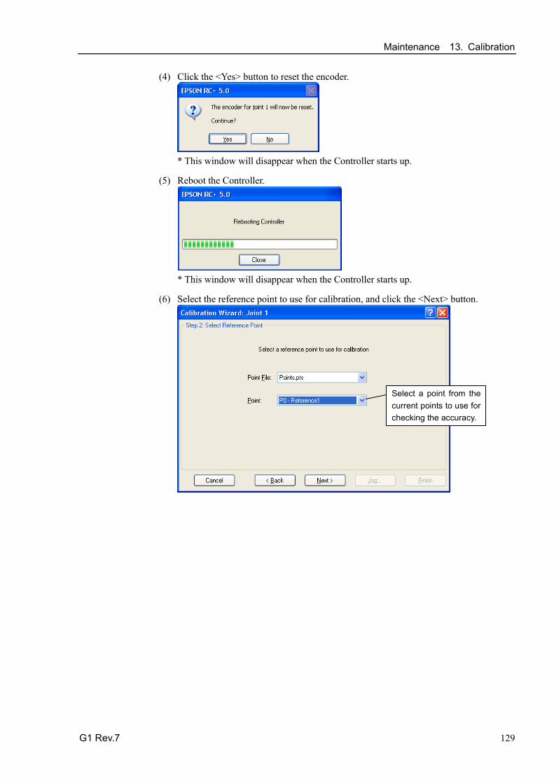
Maintenance 13. Calibration
G1 Rev.7 129
(4) Click the <Yes> button to reset the encoder.
* This window will disappear when the Controller starts up.
(5) Reboot the Controller.
* This window will disappear when the Controller starts up.
(6) Select the reference point to use for calibration, and click the <Next> button.
Select a point from the current points to use for checking the accuracy.

Maintenance 13. Calibration
130 G1 Rev.7
(7) Click the <Jog…> button to display the [Jog & Teach] dialog.
(8) Jog the end effector to approximate reference point in the [Jog & Teach] dialog for rough calibration. Then click the <OK> button. * Before operating the robot, open the [Jog & Teach] tab and click on the <Motor ON> button.
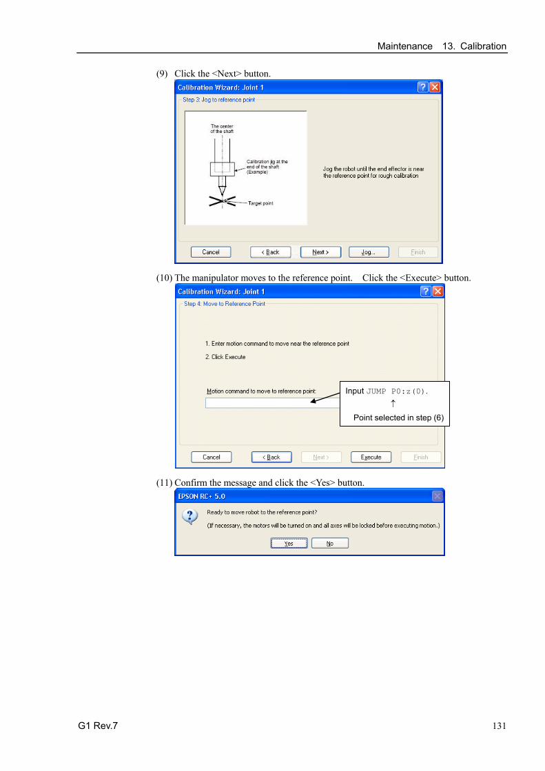
Maintenance 13. Calibration
G1 Rev.7 131
(9) Click the <Next> button.
(10) The manipulator moves to the reference point. Click the <Execute> button.
Input JUMP P0:z(0). ↑ Point selected in step (6)
(11) Confirm the message and click the <Yes> button.

Maintenance 13. Calibration
132 G1 Rev.7
(12) After the manipulator moves to the reference point, click the <Next> button.
JUMP P0:z(0)
(13) Jog to the accurate reference position. Click the <Jog> button.

Maintenance 13. Calibration
G1 Rev.7 133
(14) Jog the end effector to approximate reference point in the [Jog & Teach] dialog for rough calibration. Then click the <OK> button.
* Position Joint #2 only and move Joint #3 to around 0 pulse.
(15) Click the <Next> button.
Maintenance 13. Calibration
134 G1 Rev.7
(16) Execute the procedure in “Calibration Using Right / Left Arm Orientations” to accurately calibrate Joint #2 only. * Go on to the step (17) for the other joints calibration.
i. Move to another point that has different pose (from righty to lefty) using Jump command. Click the <Yes> button.
ii. Jog to the accurate reference position. Click the <Jog> button.
iii. Jog to the accurate reference position and adjust the position. Click the <OK> button.

Maintenance 13. Calibration
G1 Rev.7 135
iv. Click the <Next> button.
(17) Calibration is complete. Click the <Finish> button.
(18) Move the manipulator to other points and check if it can move without problems. Teach points where appropriate.

Maintenance 13. Calibration
136 G1 Rev.7
13.3 Accurate Calibration of Joint #2 When coordinates for the Manipulator working point require calculation, it is important for Joint #2 to be calibrated accurately. If the accuracy of Joint #2 is not obtained through the steps in the section Maintenance: 13.2 Calibration Procedure, follow the steps below “Calibration Using Right / Left Arm Orientations” to accurately calibrate Joint #2.
The reference point is the center of the ball screw spline shaft during this calibration.
When there is a misalignment between the center of the end effector and the center of the ball screw spline shaft, remove the end effector and perform the calibration of the shaft.
The center of the shaft
There is a misalignment between the center of the end effector and the center of the shaft.
Make a calibration jig as shown in the right figure and attach it on the end of the shaft to make the center of the shaft clear.
Decide a target point and mark a cross (×) on it so that you can easily verify the center of the shaft after switching the arm pose between right and left.
Calibration jig at the end of the shaft (Example)
Target point
The center of the shaft
After removing the end effector and performing the calibration, install the end effector and move the Manipulator to the teaching point to verify whether there is a positional gap. If there is a positional gap, fine-tune the installation position of the end effector and teach the point again.
Coordinates for the working point requires calculation in the following cases:
· Teaching the working point by entering the coordinate values (MDI teaching)
· Switching the arm orientation between right and left at a given point
· Using the Pallet command
· Executing CP control (such as liner or circular interpolation)
· Using the Local command
· Pose data specified with relative coordinates <Example: P1+X(100) >
· Vision Guide camera calibrations
NOTE

Maintenance 13. Calibration
G1 Rev.7 137
Calibration Using Right / Left Arm Orientations (1) Check the point data for calibration
Use a pose (point) you can easily verify the accuracy within the work envelop of both right and left arm. And then check the number of pose (point) you want to use.
(2) Open the Tools menu | Robot Manager | Control Panel and click the MOTOR ON.
(3) Click the Free All to free all joints from servo control. Now, you can move arms by hands.
(4) Move the arms to the position of point data for calibration in rightly arm orientation.
(5) From the current position, teach any point data number unused. This pose (point) is now called P1.
Specify the point number “1” and click the <Teach> button in the [Jog & Teach].
(6) Click the Lock All in the [Control Panel] to lock all joints under servo control.
(7) Switch to the lefty arm orientation. Then, move the arm to the same point.
>Jump P1/L:Z(0) ' Change the arm orientation from righty to lefty Z is the maximum position
* If any interference on the way from right to lefty, click the Free All in the [Control Panel] and change the arm orientation to lefty by hands. Then, go to the step (6), (7).
(8) The joints are slightly out of position.
Adjust the gap with the −Z in the Jogging group in the [Jog & Teach]. Then, teach another point data number unused. This pose (point) is now called P2.
Specify point number “P2” and click the <Teach> button in [Jog & Teach].
(9) Input the new Hofs value.
> Hofs Hofs (1), Hofs (2) + (Ppls(P1,2) + Ppls(P2,2)) /
2, Hofs(3), Hofs(4)
(10) From the current lefty arm orientation (the position in the step (8)), teach the point data number used in the step (8). This pose (point) is called P2.
Specify point number “P2” and click the <Teach> button in [Jog & Teach].
(11) Switch to the righty arm orientation. Then, make sure the manipulator move to the correct position.
>Jump P2/R ' Change the arm orientation from lefty to righty
* If there is any interference on the way from lefty to righty, click the Free All in the [Control Panel] and change the arm orientation to righty by hands. Then, go to the step (6), (11).

Maintenance 13. Calibration
138 G1 Rev.7
(12) Move the manipulator to other point data and make sure it moves to the correct position. Teach some more points if required.
* Delete the two points taught for the Joint #2 calibration.
13.4 Calibration Procedure without using Calibration Wizard
This section indicates the calibration without using the calibration wizard of EPSON RC+. For details of calibration using the calibration wizard, refer to Maintenance: 13.2 Calibration Procedure. When coordinates for the Manipulator working point require calculation, it is important for Joint #2 to be calibrated accurately. Execute the procedure in “Calibration Using Right / Left Arm Orientations” to accurately calibrate Joint #2. For details, refer to Maintenance: 13.3 Accurate Calibration of Joint #2. You cannot calibrate Joint #4 alone because of the structure of the Manipulator. When calibrating Joint #4, you must calibrate Joint #3 and #4 at the same time. The reference point (a point to identify the position of the manipulator) needs to be specified for calibration.
Follow steps 1 to 6 described below in order to calibrate the origin.
1. Basic Pose Confirmation
(1)-1 After the part replacement, perform the calibration using the point data currently registered. Confirm the point data number (P*) to reconstruct the correct manipulator position.
* Point data before the parts replacement (motor, reduction gear, belt, etc.) is necessary for the calibration.
2. Part Replacement
(2)-1 Replace parts as dictated by this manual. Be careful not to injure yourself or damage parts during part replacement.
3. Encoder Initialization
(3)-1 Turn ON the Controller when all joints are in the motion range.
(3)-2 Manually move the joint that needs origin alignment to its approximate 0 pulse position.
NOTE
NOTE

Maintenance 13. Calibration
G1 Rev.7 139
0 pulse position of Joint #1: position aligned with X-axis in Robot coordinate system
0 pulse
0 pulse position of Joint #2: position where Arms #1 and #2 are in a straight line (Regardless of the Joint #1 direction.)
0 pulse
0 pulse position of Joint #3: upper limit position in motion range
The height of Joint #3 depends on manipulator model.
Standard model Cleanroom model
0 pulse position of Joint #4: position where the flat surface (or screw hole 1) on the shaft faces toward the tip of Arm #2
Flat surface
Screw hole 2 Screw hole 1
0 pulse
Screw hole 1 and flat surface are located in the center of the shaft.
Screw hole 1 and 2 are located at right angles to one another.

Maintenance 13. Calibration
140 G1 Rev.7
(3)-3 Connect EPSON RC+ to the Controller.
Select a robot to be calibrated. Input as below in the [Command Window] and execute it. (This example uses “robot 1”.)
> robot 1
(3)-4 Execute the absolute encoder initialization command.
Input one of the following commands to [Command Window] according to the joint being calibrated.
Joint #1: >EncReset 1 Joint #2: >EncReset 2 Joint #3: >EncReset 3 Joint #4: >EncReset 3, 4
(3)-5 Reboot the Controller.
Select EPSON RC+ menu-[Tools]-[Controller] and click the <Reset Controller> button.
* This window will be disappeared when the Controller starts up.
4. Rough Calibration
(4)-1 Turn ON the motor from EPSON RC+ menu-[Tools]-[Robot Manager]- [Controller Panel].
(4)-2 Click the <Free All> button in the [Control Panel] page to free all joints and move the arms manually.
(4)-3 Move the Manipulator to the approximate position and orientation.
(4)-4 To perform temporary calibration, input the pulse value of the specified point data. When the specified point data is “P1,” input and perform the following command to [Command Window] according to the joint being calibrated.
> Calpls Ppls(P1,1), Ppls(P1,2), Ppls(P1,3), Ppls(P1,4)
EPSON RC+ 6.0
EPSON RC+ 7.0

Maintenance 13. Calibration
G1 Rev.7 141
(4)-5 Perform the temporary calibration.
Input and perform one of the following commands to [Command Window] according to the joint being calibrated.
Joint #1: >Calib 1 Joint #2: >Calib 2 Joint #3:: >Calib 3 Joint #4: >Calib 3, 4
5. Calibration (Accurate Positioning)
(5)-1 Click the <Lock All> button in [Control Panel] to put all joints back under servo control.
(5)-2 Move the joint to the specified point using a motion command.
For example, when the specified point data is “P1”, click <MOTOR ON> button in [Control Panel] and execute “Jump P1:Z(0)” from [Jog & Teach].
* The joint NOT being calibrated moves to the original position.
(5)-3 Accurately align the joint* being calibrated to the specified point using jog commands.
* You must move Joint #3 and #4 to the position when calibrating Joint #4.
Select the jog mode [Joint] from [Jog & Teach] to execute the jog motion.
(5)-4 Perform the calibration.
Input and perform one of the following commands to [Command Window] according to the joint being calibrated.
Joint #1: >Calib 1 Joint #2: >Calib 2 Joint #3: >Calib 3 Joint #4: >Calib 3, 4
6. Accuracy Testing
(6)-1 Move the Manipulator to another point to confirm that it moves to the same position. If it does not move to the same position, re-calibrate using another point. You must set the point again if reproducibility cannot be assured through calibration.

Maintenance 14. Maintenance Parts list
142 G1 Rev.7
14. Maintenance Parts List
14.1 Common Parts Part Name Code Note Reference:
Maintenance Overhaul
*1
AC Servo Motor
Joint #1 R13B000621
50 W
5.1 Joint #2
R13B000619 6.1
Joint #3 7.1 Joint #4 8.1
Reduction Gear Unit Joint #1 R13B010026 5.2 Joint #2 R13B010027 6.2
Electromagnetic Brake Z axis R13B030507 7.3
Timing Belt Joint #3 R13B030226 Z : width 6 mm, length 196 mm 7.2 Joint #4 R13B030227 U : width 6 mm, length 190 mm 8.2
Cable Unit 175mm R13B020039 4.1 225mm R13B020040 4.1
M/C Cable
R12B020446 3 m
For RC180, RC620
4.3
R12NZ900KG For RC700-A, Straight R12NZ900KK For RC700-A, L-shaped R12B020447
5 m For RC180, RC620
R12NZ900KH For RC700-A, Straight R12NZ900KL For RC700-A, L-shaped R12B020448
10 m For RC180, RC620
R12NZ900KJ For RC700-A, Straight R12NZ900KM For RC700-A, L-shaped
Battery Board R13B041203 No lithium battery Installed in Base 11.1
Battery Unit R13ZA00600300 Lithium battery for replacement ER17330V (TOSHIBA)
11
O-ring Joint #1 R13B031251 For Joint # motor flange 5.1 Joint #2 R13B031252 For Joint #2 motor flange 6.1
Brake Release Switch R13Z702640100 - LED Lamp R13B030004 12
Grease
AFB (Ball Screw Spline)
- For purchasing the grease, please contact the sales company in your region.
2.3
SK-1A (Reduction Gear Unit)
- 2.3
GPL-224 (Cable) - - Liquid gasket 1206C 10.2
*1 As a rough indication, perform the overhaul (parts replacement) before reaching 20,000 operation hours of the Manipulator. The operation hours can be checked in [Controller Status Viewer] dialog - [Motor On Hours]. For details, refer to Maintenance 2.2 Overhaul.
Maintenance 14. Maintenance Parts list
G1 Rev.7 143
14.2 Parts by Environment Model
14.2.1 S: Standard-model
Part Name Code Note Reference:
Maintenance Overhaul *1
Ball Screw Spline 4-axis spec R13B010224 10.2.1 3-axis spec R13B010226 10.2.2
Arm Cover R13B030441 White 3.1
*1 As a rough indication, perform the overhaul (parts replacement) before reaching 20,000 operation hours of the Manipulator. The operation hours can be checked in [Controller Status Viewer] dialog - [Motor On Hours]. For details, refer to Maintenance 2.2 Overhaul.
14.2.2 C: Cleanroom-model
Part Name Code Note Reference:
Maintenance Overhaul *1
Ball Screw Spline 4-axis spec R13B010225 10.2.1 3-axis spec R13B010227 10.2.2
Arm Cover R13B030442 Plating 3.1
Bellows 4-axis spec R13B030706 9.1 3-axis spec R13B030707 9.2
Gasket Unit R13B031253 -
*1 As a rough indication, perform the overhaul (parts replacement) before reaching 20,000 operation hours of the Manipulator. The operation hours can be checked in [Controller Status Viewer] dialog - [Motor On Hours]. For details, refer to Maintenance 2.2 Overhaul.

Maintenance 14. Maintenance Parts list
144 G1 Rev.7