Scanner Data Parameters Euro
250
Adptors Overview and Data Parameters August 2008 ZEESCGB234A3 Rev. S
Transcript of Scanner Data Parameters Euro

Adptors Overview and Data Parameters
August 2008
ZEESCGB234A3 Rev. S

Disclaimer of Warranties and Limitations of LiabilitiesWhile the authors have taken due care in the preparation of this manual, nothing contained herein:
• modifies or alters in any way the standard terms and conditions of the purchase, lease or rental agreement under the terms of which the equipment to which this manual relates was acquired,
• increases in any way the liability to the customer or to third parties.
To the ReaderWhile every effort has been made to ensure that the information contained in this manual is correct, complete and up-to date, the right to change any part of this document at any time without prior notice is reserved.
Warning:Warning:ä Before installing, maintaining or operating this unit, please read
this manual carefully, paying extra attention to the safety warnings and precautions.
Copyright 2006 Snap-on UK Holdings Ltd.
All Rights Reserved
Snap-on DiagnosticsUnit 1B, Boland Industrial EstateMallow RoadCorkIrelandTel: +353.21.4211600Fax: +353.21.4211601
Web-sites:
http://www.sun-diagnostics.com/
http://www.snapon.com/

Adaptors Overview & Data Parameters 2007-10
Trademark Information
SCANBAY II™, Scanner™, Scan Gra-Fix, Scan-Link, ScanView, TechWare, MODIS™, SOLUS™, Sun and Snap-on are trademarks of Snap-on Incorporated, registered in the United States and in other countries. All other marks, logos or names are the property of their respective owners.

i
Table of Contents
Table of Contents . . . . . . . . . . . . . . . . . . . . . . . . . . . . . . i
1 Adaptors Overview . . . . . . . . . . . . . . . . . . . . . . . . . . . . .1
2 Abbreviations . . . . . . . . . . . . . . . . . . . . . . . . . . . . . . . . .7
3 Data Parameters . . . . . . . . . . . . . . . . . . . . . . . . . . . . . .153.1 Introduction . . . . . . . . . . . . . . . . . . . . . . . . . . . . . . . . . . . . . . . . . . . 15
3.2 Data Parameters List . . . . . . . . . . . . . . . . . . . . . . . . . . . . . . . . . . . . 173.2.1 Numerical . . . . . . . . . . . . . . . . . . . . . . . . . . . . . . . . . . . . . . 173.2.2 A . . . . . . . . . . . . . . . . . . . . . . . . . . . . . . . . . . . . . . . . . . . . . 183.2.3 B . . . . . . . . . . . . . . . . . . . . . . . . . . . . . . . . . . . . . . . . . . . . . 423.2.4 C . . . . . . . . . . . . . . . . . . . . . . . . . . . . . . . . . . . . . . . . . . . . . 493.2.5 D . . . . . . . . . . . . . . . . . . . . . . . . . . . . . . . . . . . . . . . . . . . . . 743.2.6 E . . . . . . . . . . . . . . . . . . . . . . . . . . . . . . . . . . . . . . . . . . . . . 853.2.7 F . . . . . . . . . . . . . . . . . . . . . . . . . . . . . . . . . . . . . . . . . . . . . 993.2.8 G . . . . . . . . . . . . . . . . . . . . . . . . . . . . . . . . . . . . . . . . . . . 1093.2.9 H . . . . . . . . . . . . . . . . . . . . . . . . . . . . . . . . . . . . . . . . . . . . 1123.2.10 I . . . . . . . . . . . . . . . . . . . . . . . . . . . . . . . . . . . . . . . . . . . . 1173.2.11 K . . . . . . . . . . . . . . . . . . . . . . . . . . . . . . . . . . . . . . . . . . . . 1363.2.12 L . . . . . . . . . . . . . . . . . . . . . . . . . . . . . . . . . . . . . . . . . . . . 1403.2.13 M . . . . . . . . . . . . . . . . . . . . . . . . . . . . . . . . . . . . . . . . . . . 1513.2.14 N . . . . . . . . . . . . . . . . . . . . . . . . . . . . . . . . . . . . . . . . . . . . 1593.2.15 O . . . . . . . . . . . . . . . . . . . . . . . . . . . . . . . . . . . . . . . . . . . 1623.2.16 P . . . . . . . . . . . . . . . . . . . . . . . . . . . . . . . . . . . . . . . . . . . . 1763.2.17 Q . . . . . . . . . . . . . . . . . . . . . . . . . . . . . . . . . . . . . . . . . . . 1873.2.18 R . . . . . . . . . . . . . . . . . . . . . . . . . . . . . . . . . . . . . . . . . . . . 1883.2.19 S . . . . . . . . . . . . . . . . . . . . . . . . . . . . . . . . . . . . . . . . . . . . 2033.2.20 T . . . . . . . . . . . . . . . . . . . . . . . . . . . . . . . . . . . . . . . . . . . . 2233.2.21 U . . . . . . . . . . . . . . . . . . . . . . . . . . . . . . . . . . . . . . . . . . . . 2363.2.22 V . . . . . . . . . . . . . . . . . . . . . . . . . . . . . . . . . . . . . . . . . . . . 2373.2.23 W . . . . . . . . . . . . . . . . . . . . . . . . . . . . . . . . . . . . . . . . . . . 241

ii Adaptors Overview & Data Parameters 2007-10
TABLE OF CONTENTS
3.2.24 X . . . . . . . . . . . . . . . . . . . . . . . . . . . . . . . . . . . . . . . . . . . .2443.2.25 Y . . . . . . . . . . . . . . . . . . . . . . . . . . . . . . . . . . . . . . . . . . . .2443.2.26 Z . . . . . . . . . . . . . . . . . . . . . . . . . . . . . . . . . . . . . . . . . . . .245
1
1 Adaptors Overview
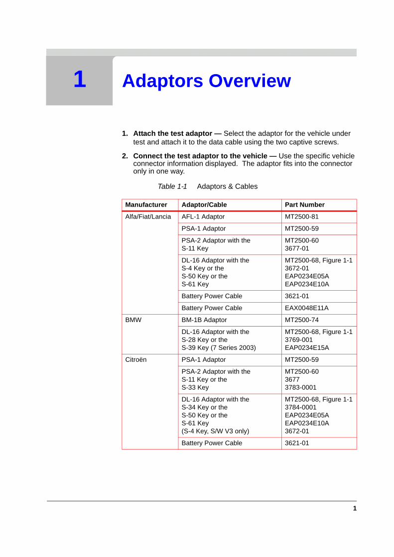
1. Attach the test adaptor — Select the adaptor for the vehicle under test and attach it to the data cable using the two captive screws.
2. Connect the test adaptor to the vehicle — Use the specific vehicle connector information displayed. The adaptor fits into the connector only in one way.
Table 1-1 Adaptors & Cables
Manufacturer Adaptor/Cable Part Number
Alfa/Fiat/Lancia AFL-1 Adaptor MT2500-81
PSA-1 Adaptor MT2500-59
PSA-2 Adaptor with theS-11 Key
MT2500-603677-01
DL-16 Adaptor with theS-4 Key or theS-50 Key or theS-61 Key
MT2500-68, Figure 1-13672-01EAP0234E05AEAP0234E10A
Battery Power Cable 3621-01
Battery Power Cable EAX0048E11A
BMW BM-1B Adaptor MT2500-74
DL-16 Adaptor with theS-28 Key or theS-39 Key (7 Series 2003)
MT2500-68, Figure 1-13769-001EAP0234E15A
Citroën PSA-1 Adaptor MT2500-59
PSA-2 Adaptor with theS-11 Key or theS-33 Key
MT2500-6036773783-0001
DL-16 Adaptor with theS-34 Key or theS-50 Key or theS-61 Key(S-4 Key, S/W V3 only)
MT2500-68, Figure 1-13784-0001EAP0234E05AEAP0234E10A3672-01
Battery Power Cable 3621-01

2 Adaptors Overview & Data Parameters 2007-10
C H A P T E R 1 ADAPTORS OVERVIEW
EOBD DL-16 Adaptor with theS-7 Key or theS-44 key
MT2500-68, Figure 1-13655-01EAP0234E50A
CAN-1 Adaptor (EU) EAA0281E77C
CAN-1 Adaptor (USA) MT2500-83A
CAN-1A Adaptor (Australia) EAA0281E77D
CAN-1B Adaptor (Universal) EAA0281E77E
OBD-II (USA) with theK-2A or theK-20 key
MT2500-465078-0202EAP0234E45A
Ford Ford-3 Adaptor MT2500-67
Power Adaptor MT2500-91
DL-16 Adaptor with theS-2A Key or theS-7 Key or theS-43 Key
MT2500-68, Figure 1-1EAP0234E00A3655-01 EAP0234E40A
GA-1 Adaptor MT2500-45
Honda DL-16 Adaptor with theS-7 Key or theS-46 Key (Honda SRS)
MT2500-68, Figure 1-13655-01EAP0234E60A
HON-1 Adaptor MT2500-77
Land Rover MULTI-4 Adaptor MT2500-21
ROV-1 MT2500-71
Power Adaptor MT2500-91
DL-16 Adaptor with theS-25 Key
MT2500-68, Figure 1-13745-01
Table 1-1 Adaptors & Cables
Manufacturer Adaptor/Cable Part Number

3
Mercedes MB-1 Adaptor with theS-20 Key or theS-21 Key
MT2500-623693-013694-01
MB-2 with theBattery Power Cable
MT2500-723621-01
DL-14 Adaptor MT2500-73
DL-16 Adaptor with theS-4 Key or theS-17 Key or theS-34 Key
MT2500-68, Figure 1-13672-013692-013784-0001
2.5 mm Adaptor Cable 6004E9312-98
PSA-2 Adaptor with theS-11 Key or theS-33 Key
MT2500-6036773783-0001
MG/Rover MULTI-4 Adaptor MT2500-21
ROV-1 MT2500-71
Power Adaptor MT2500-91
DL-16 Adaptor with theS-25 Key
MT2500-68, Figure 1-13745-01
Nissan DL-16 Adaptor with theS-7 Key
MT2500-68, Figure 1-13655-01
DL-16 Adaptor with theS-45 Key
MT2500-68, Figure 1-1EAP0234E55A
NISS-2 Adaptor MT2500-58
Opel/Vauxhall OPEL/VAUXHALL-2 MT2500-66
DL-16 Adaptor with theS-26 Key or theS-27 Key or theS-32 Key (ABS + Airbag) or theS-47 Key
MT2500-68, Figure 1-13752-0013768-00013778-0001EAP0234E70A
Peugeot PSA-1 Adaptor MT2500-59
PSA-2 Adaptor with theS-11 Key or theS-33 Key
MT2500-6036773783-0001
DL-16 Adaptor with theS-34 Key or theS-50 Key or theS-61 Key(S-4 Key, S/W V3 only)
MT2500-68, Figure 1-13784-0001EAP0234E05AEAP0234E10A3672-01
Battery Power Cable 3621-01
Table 1-1 Adaptors & Cables
Manufacturer Adaptor/Cable Part Number
4 Adaptors Overview & Data Parameters 2007-10
C H A P T E R 1 ADAPTORS OVERVIEW
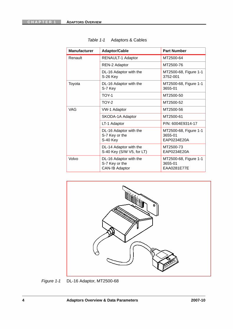
Figure 1-1 DL-16 Adaptor, MT2500-68
Renault RENAULT-1 Adaptor MT2500-64
REN-2 Adaptor MT2500-76
DL-16 Adaptor with theS-26 Key
MT2500-68, Figure 1-13752-001
Toyota DL-16 Adaptor with theS-7 Key
MT2500-68, Figure 1-13655-01
TOY-1 MT2500-50
TOY-2 MT2500-52
VAG VW-1 Adaptor MT2500-56
SKODA-1A Adaptor MT2500-61
LT-1 Adaptor P/N: 6004E9314-17
DL-16 Adaptor with theS-7 Key or theS-40 Key
MT2500-68, Figure 1-13655-01EAP0234E20A
DL-14 Adaptor with theS-40 Key (S/W V5, for LT)
MT2500-73EAP0234E20A
Volvo DL-16 Adaptor with theS-7 Key or theCAN-!B Adaptor
MT2500-68, Figure 1-13655-01 EAA0281E77E
Table 1-1 Adaptors & Cables
Manufacturer Adaptor/Cable Part Number

5
Caution:ä Do NOT connect the DL-16 to a 24 V version OBD socket. This
might damage the unit.
Figure 1-2 OBD Sockets 12 V (Left) and 24 V (Right)

6 Adaptors Overview & Data Parameters 2007-10
C H A P T E R 1 ADAPTORS OVERVIEW

7
2 Abbreviations
The following abbreviations and terms are used in the fault code definitions displayed on the screen or used in manufacturers literature:
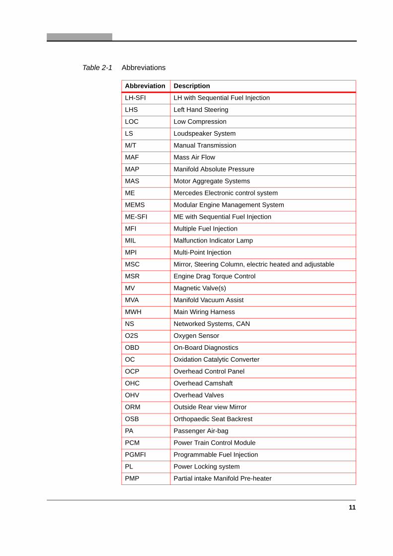
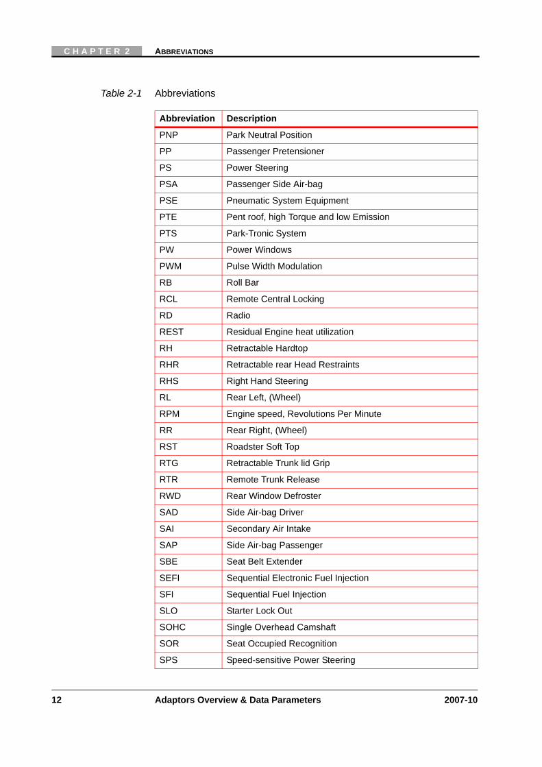
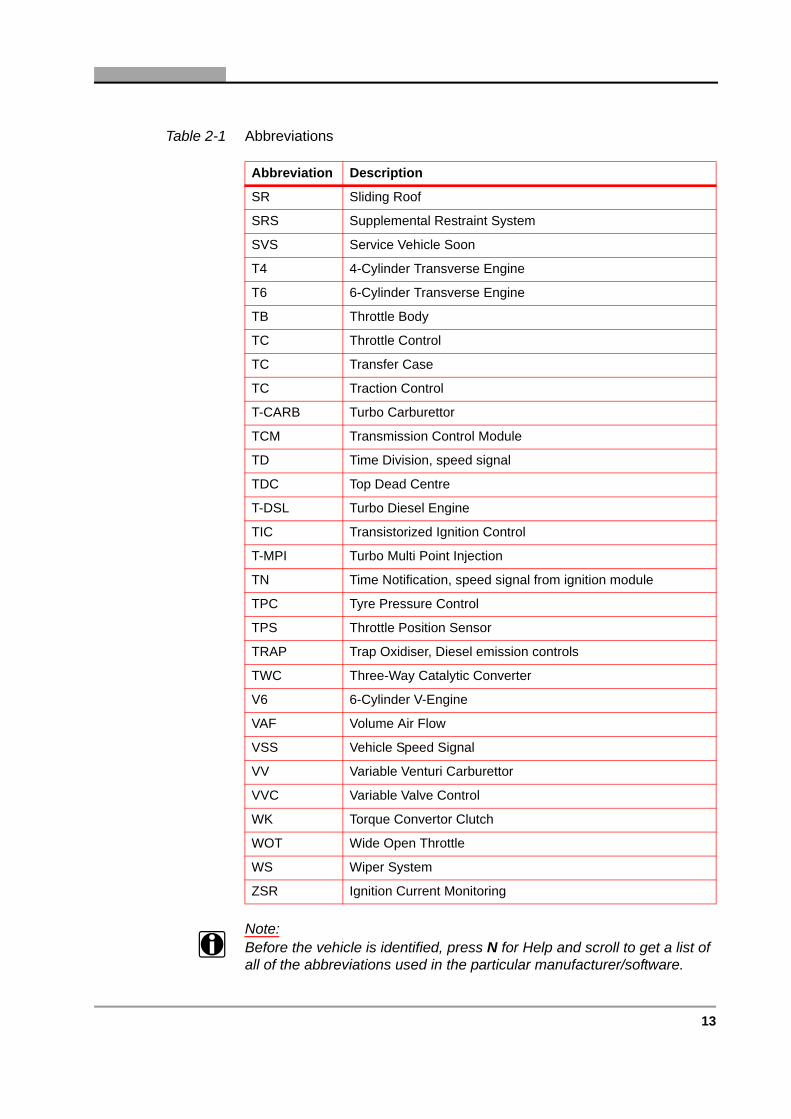
Table 2-1 Abbreviations
Abbreviation Description
1BL One Barrel Carburettor
2BL Two Barrel Carburettor
4MATIC Automatically controlled four-wheel drive
A/C Air Conditioning
A/T Automatic Transmission
AAC Automatic Air Conditioning
AAM All Activity Module
AB Air-bag
ABS Anti-lock Brake System
ACRS Automatic Child Seat Recognition
ADM Automatic Dimming Mirror, inside rear view
ADS Automatic Damping System, electronic suspension
AIR Secondary air injection
AP Accelerator Pedal
APP Accelerator Pedal Position
APS Auto Pilot System
AS Antenna System
ASC Anti-spin Control
ASD Automatic Slip Differential, limited-slip
ASR Acceleration Slip Regulation, traction control
ATA Anti-Theft Alarm
BA Backup Assist
BARO Barometric pressure
BCAPC Barometric Charge Air Pressure Compensation
BDC Bottom Dead Centre

8 Adaptors Overview & Data Parameters 2007-10
C H A P T E R 2 ABBREVIATIONS
BM Base Module, also called General Module (GM) or Controller Area Network (CAN) Bus Module
BPC Barometric Pressure Compensation
C/C Cruise Control
CA Cooling Assist
CAN Controller Area Network
CARB Carburettor
CAT Catalytic Converter
CCM Combination Control Module
CDC Compact Disc Changer
CF Convenience Feature
CFI Central Fuel Injection
CKA Crankshaft Angle
CKP Crankshaft Position
CL Central Locking
CMP Camshaft Position
CNS Communication and Navigation System
CPI Central Point Injection
CST Cabriolet Soft Top
CTEL Cellular Telephone
CTP Closed Throttle Position
CTU Central Triggering Unit
CVH Compound Valve Angle Head
DA Drivers Air Bag
DAS Drive Authorization System
DDE Diesel engine management
DI Distributor Ignition
DM Diagnostic Module
DME Engine Management
DOHC Double Overhead Camshaft
DP Drivers Pretensioner
DSA Drivers Side Air-bag
DSC Dynamic Stability Control
Table 2-1 Abbreviations
Abbreviation Description

9
DSL Diesel Engine
DSV Drive authorization Shut-off Valve
DTC Diagnostic Trouble Code
DWA Anti-theft System
EA Electronic Accelerator
EBR Electronic Braking Regulation
ECL Engine Coolant Level
ECT Engine Coolant Temperature
ECU Electronic Control Unit
EDC Electronic Diesel Control
EDR Electronic Diesel Regulation
EDS Electronic Diesel System
EDS Pressure Regulator
EEC Electronic Engine Control
EFI Electronic Fuel Injection
EGR Exhaust Gas Recirculation
EGS Electronic Transmission
EI Electronic Ignition, Distributorless
EL Exterior Lighting
EML Electronic Throttle
EMS Electronic Throttle
EMSC Electric Mirror and Steering Column, heated and adjustment
EPC Electronic Power Control
ERIC Electronically Regulated & Carburation Ignition System
ESA Electric Seat Adjustment
ESC Electric Steering Column adjustment
ESCM Engine Systems Control Module, also called MAS
ESP Electronic Stability Control, (traction control)
ETC Electronic Transmission Control
ETC Electronic Throttle Control
ETR Emergency Tensioning Retractor, supplemental restraints
ETS Electronic Traction System
EVAP Evaporative emission control system
Table 2-1 Abbreviations
Abbreviation Description

10 Adaptors Overview & Data Parameters 2007-10
C H A P T E R 2 ABBREVIATIONS
EWS Anti-theft System
FAN Cooling Fan or Fanfare Horns
FFS Frame Floor System
FI Fuel Injection
FL Front Left, (Wheel)
FOM Folding Outside Mirrors
FP Fuel Pump
FR Front Right, (Wheel)
GIM Governor Impulse Method
GM General Module, also called Base Module (BM)
HCS High Compression Swirl
HCS Headlamp Cleaning System
HFM Hot Film engine Management system
HFM-SFI HFM with Sequential Fuel Injection
HFS Hands Free System
HHT Hand Held Tester
HM Heated Mirrors
HORN Horn signal system
HS Heated Seats
IAT Intake Air Temperature
IC Instrument Cluster
IDC In-Dash Controller
IFI In-line Fuel Injection
IL Interior Lighting
IMRC Intake Manifold Running Control
IR Infrared
IRM Inside Rear view Mirror
ISC Idle Speed Control
KS Knock Sensor
KSS Knock Sensor System
L4 4-Cylinder Line Engine
LCP Lower Control Panel
LH Lambda Hot wire mass airflow system
Table 2-1 Abbreviations
Abbreviation Description
11
LH-SFI LH with Sequential Fuel Injection
LHS Left Hand Steering
LOC Low Compression
LS Loudspeaker System
M/T Manual Transmission
MAF Mass Air Flow
MAP Manifold Absolute Pressure
MAS Motor Aggregate Systems
ME Mercedes Electronic control system
MEMS Modular Engine Management System
ME-SFI ME with Sequential Fuel Injection
MFI Multiple Fuel Injection
MIL Malfunction Indicator Lamp
MPI Multi-Point Injection
MSC Mirror, Steering Column, electric heated and adjustable
MSR Engine Drag Torque Control
MV Magnetic Valve(s)
MVA Manifold Vacuum Assist
MWH Main Wiring Harness
NS Networked Systems, CAN
O2S Oxygen Sensor
OBD On-Board Diagnostics
OC Oxidation Catalytic Converter
OCP Overhead Control Panel
OHC Overhead Camshaft
OHV Overhead Valves
ORM Outside Rear view Mirror
OSB Orthopaedic Seat Backrest
PA Passenger Air-bag
PCM Power Train Control Module
PGMFI Programmable Fuel Injection
PL Power Locking system
PMP Partial intake Manifold Pre-heater
Table 2-1 Abbreviations
Abbreviation Description
12 Adaptors Overview & Data Parameters 2007-10
C H A P T E R 2 ABBREVIATIONS
PNP Park Neutral Position
PP Passenger Pretensioner
PS Power Steering
PSA Passenger Side Air-bag
PSE Pneumatic System Equipment
PTE Pent roof, high Torque and low Emission
PTS Park-Tronic System
PW Power Windows
PWM Pulse Width Modulation
RB Roll Bar
RCL Remote Central Locking
RD Radio
REST Residual Engine heat utilization
RH Retractable Hardtop
RHR Retractable rear Head Restraints
RHS Right Hand Steering
RL Rear Left, (Wheel)
RPM Engine speed, Revolutions Per Minute
RR Rear Right, (Wheel)
RST Roadster Soft Top
RTG Retractable Trunk lid Grip
RTR Remote Trunk Release
RWD Rear Window Defroster
SAD Side Air-bag Driver
SAI Secondary Air Intake
SAP Side Air-bag Passenger
SBE Seat Belt Extender
SEFI Sequential Electronic Fuel Injection
SFI Sequential Fuel Injection
SLO Starter Lock Out
SOHC Single Overhead Camshaft
SOR Seat Occupied Recognition
SPS Speed-sensitive Power Steering
Table 2-1 Abbreviations
Abbreviation Description
13
Note:i Before the vehicle is identified, press N for Help and scroll to get a list of
all of the abbreviations used in the particular manufacturer/software.
SR Sliding Roof
SRS Supplemental Restraint System
SVS Service Vehicle Soon
T4 4-Cylinder Transverse Engine
T6 6-Cylinder Transverse Engine
TB Throttle Body
TC Throttle Control
TC Transfer Case
TC Traction Control
T-CARB Turbo Carburettor
TCM Transmission Control Module
TD Time Division, speed signal
TDC Top Dead Centre
T-DSL Turbo Diesel Engine
TIC Transistorized Ignition Control
T-MPI Turbo Multi Point Injection
TN Time Notification, speed signal from ignition module
TPC Tyre Pressure Control
TPS Throttle Position Sensor
TRAP Trap Oxidiser, Diesel emission controls
TWC Three-Way Catalytic Converter
V6 6-Cylinder V-Engine
VAF Volume Air Flow
VSS Vehicle Speed Signal
VV Variable Venturi Carburettor
VVC Variable Valve Control
WK Torque Convertor Clutch
WOT Wide Open Throttle
WS Wiper System
ZSR Ignition Current Monitoring
Table 2-1 Abbreviations
Abbreviation Description

14 Adaptors Overview & Data Parameters 2007-10
C H A P T E R 2 ABBREVIATIONS

15
3 Data Parameters
3.1 IntroductionThe ECU provides two basic kinds of parameters: digital (or discrete) and analogue.
• Digital (Discrete) parameters can be only in one of two states, such as On or Off, Open or Closed, Yes or No, etc. Switches and solenoids provide discrete parameters on the ECU data list.
• Analogue parameters are quantities displayed as a measured value in the appropriate units. Voltage, pressure, temperature, time and speed parameters are examples of analogue values.
Refer to the tables below for more information concerning the units of measurement used.
If the letter “X” is shown in/after data parameter title, a software counter applied to that particular parameter, e.g. COIL X, where X is a number such as 1, 2, 3, etc.
All data parameters are listed alphabetically.
Note:i Some Data Parameters maybe incorrect until the engine is running, for
example IDLE LOAD, FULL LOAD, etc.
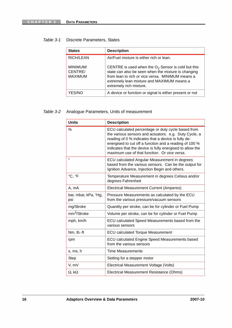
Table 3-1 Discrete Parameters, States
States Description
ACTIVE/INACTIVE A device or feature is active or not
ENABLE/DISABLE A device or feature is enabled or not
HIGH/LOW A device or function or signal is operating either in high or low mode
OK/NOT OK A device or parameter is either OK or NOT OK
ON/OFF A device is either switched ON or OFF
OPEN/CLSD A device is either open or closed, Solenoid Valves, etc.
PETROL/GAS Engine is running on petrol or gas
16 Adaptors Overview & Data Parameters 2007-10
C H A P T E R 3 DATA PARAMETERS
RICH/LEAN
MINIMUM/CENTRE/MAXIMUM
Air/Fuel mixture is either rich or lean.
CENTRE is used when the O2 Sensor is cold but this state can also be seen when the mixture is changing from lean to rich or vice versa. MINIMUM means a extremely lean mixture and MAXIMUM means a extremely rich mixture.
YES/NO A device or function or signal is either present or not
Table 3-1 Discrete Parameters, States
States Description
Table 3-2 Analogue Parameters, Units of measurement
Units Description
% ECU calculated percentage or duty cycle based from the various sensors and actuators. e.g. Duty Cycle, a reading of 0 % indicates that a device is fully de-energised to cut off a function and a reading of 100 % indicates that the device is fully energised to allow the maximum use of that function. Or vice versa.
° ECU calculated Angular Measurement in degrees based from the various sensors. Can be the output for Ignition Advance, Injection Begin and others.
°C, °F Temperature Measurement in degrees Celsius and/or degrees Fahrenheit
A, mA Electrical Measurement Current (Amperes)
bar, mbar, kPa, “Hg, psi
Pressure Measurements as calculated by the ECU from the various pressure/vacuum sensors
mg/Stroke Quantity per stroke, can be for cylinder or Fuel Pump
mm3/Stroke Volume per stroke, can be for cylinder or Fuel Pump
mph, km/h ECU calculated Speed Measurements based from the various sensors
Nm, lb.-ft ECU calculated Torque Measurement
rpm ECU calculated Engine Speed Measurements based from the various sensors
s, ms, h Time Measurements
Step Setting for a stepper motor
V, mV Electrical Measurement Voltage (Volts)
Ω, kΩ Electrical Measurement Resistance (Ohms)

17
DATA PARAMETERS LIST
3.2 Data Parameters List
3.2.1 Numerical# OF KEYS STORED IN MODULE
Indicates the number of valid ignition keys programmed into the system.
(ASR/ESP-STATUS)ABS/ASR_MODEIndicates the status of the ASR/ESP-ABS mode.
(ASR/ESP-STATUS)ASRIndicates the status of the ASR/ESP
(ASR/ESP-STATUS)CRUISE CONTROL MODEIndicates the status of the ASR/ESP-Cruise Control mode.
1ST GEARIndicates whether the Transmission is in 1st gear.
1ST/RV.GEARIndicates whether 1st or Reverse Gear is selected.
2ND GEARIndicates whether 2nd Gear is selected.
2ND INPUT CIRCUIT 502nd input circuit 50.
2ND LAST ALARM ACTIVATIONAlarm source of the 2nd last ATA activation.
3RD GEARIndicates whether 3rd Gear is selected.
3RD LAST ALARM ACTIVATIONAlarm source of the 3rd last ATA activation.
4TH GEARIndicates whether 4th Gear is selected.
4TH LAST ALARM ACTIVATIONAlarm source of the 4th last ATA activation.
4WD CLUTCH DCIndicates the amount of transfer case clutch lockup commanded by the GEM module. When the front and rear axles rotate at the same speed, 4WD Clutch DC(%) should display 0 to 2 %.
4WD CLUTCH PWMIndicates whether the GEM module is controlling the transfer case clutch using pulse width modulation (PWM). ON means that the GEM is using PWM.
4WD ELECTRIC CLUTCHIndicates whether the 4-Wheel Drive Electric Clutch is on or off.

18 Adaptors Overview & Data Parameters 2007-10
C H A P T E R 3 DATA PARAMETERS
4WD FRONT T-CASE SHAFT SPEEDDisplays the speeds in mph of the front transfer case drive shafts. Using the speeds of these two shafts, the GEM module calculates the amount of wheel slippage between the front and rear axles. The amount of wheel slippage determines how much the GEM module applies the 4WD clutch.
4WD HIGH OUT STATEIndicates the GEM command status to run the transfer case in 4WD High Mode. When the system functions properly, ON means the transfer case is running in 4WD High Mode.
4WD LOW OUT STATEIndicates the GEM command status to run the transfer case in 4WD Low Mode. When the system functions properly, ON means the transfer case is running in 4WD Low Mode.
4WD PLATE POWERIndicates whether the 4-Wheel Drive Electric Clutch is receiving power.
4WD REAR T-CASE SHAFT SPEEDDisplays the speeds in mph of the rear transfer case drive shafts. Using the speeds of these two shafts, the GEM module calculates the amount of wheel slippage between the front and rear axles. The amount of wheel slippage determines how much the GEM module applies the 4WD clutch.
4WD TRANSFER CONTACT PLATE XIndicates whether the 4-Wheel Drive Clutch plates are open or closed.
5TH GEARIndicates if 5th Gear has been selected.
5TH LAST ALARM ACTIVATIONAlarm source of the 5th last ATA activation.
6TH GEARIndicates whether 6th Gear is selected.
91 RON TABLE IN USEThis parameter gives the Research Octane Number (RON) table values and is used by the ECU to determine the ignition timing characteristics.
95 RON TABLE IN USEThis parameter gives the Research Octane Number (RON) table values and is used by the ECU to determine the ignition timing characteristics.
3.2.2 AA ACT.MODE
Indicates the status of the “A” Actuator Mode.

19
DATA PARAMETERS LIST
A/C ACTIVEThis parameter indicates the position of the air conditioning cycle switch. ON means that the A/C switch on the instrument panel has been turned on or that the ECU has commanded the A/C system to turn on. In some cases, the A/C compressor may not turn on even though the switch is closed. Several other switch or sensor signals may prevent the ECU from engaging the A/C compressor clutch.
A/C AUTHOR.Indicates the status of the Airco Authorisation.
A/C BLEND DOOR POSITIONIndicates the status of the A/C Blend Door Position switch.
A/C BLOWER MOTOR OUTPUT RLYIndicates the status of the A/C Blower Motor Output Relay.
A/C BLOWER MOTOR SPEED XDisplays the specified A/C Blower Motor speed.
A/C BUTTON ECU-N22:RESPONSEResponse from component N22 (AAC pushbutton control module).
A/C CLUTCHThis parameter is a feedback signal from the A/C compressor clutch or relay. When it is ON, the clutch is engaged, when it is OFF, the clutch is disengaged. The ECU uses this signal primarily to control the idle speed.
A/C COMPRESSORIndicates the status of the A/C compressor.
A/C COMPRESSOR SIGNALIndicates the status of the A/C compressor signal. ON is displayed when the air conditioning compressor signal is activated.
A/C COMPRESSOR TEMPDisplays the A/C Compressor Temperature.
A/C CONTROL SWITCH CLOSEDIndicates ON when the A/C cycling switch is closed and OFF when the switch is open. The PCM uses this information to adjust engine speed.
A/C CUTOFFThis parameter indicates that the ECU has commanded the A/C compressor to interrupt its operation. i.e. when wide open throttle is indicated the ECU will suspend the A/C compressor operation.
A/C ENABLEThis parameter indicates whether or not the ECU allows the A/C to be used or not.
A/C EVAPORATOR TEMPDisplays the A/C Evaporator temperature.

20 Adaptors Overview & Data Parameters 2007-10
C H A P T E R 3 DATA PARAMETERS
A/C HEAD PRES SENSDisplays the voltage from the A/C Pressure sensor/switch. This is the main pressure in the A/C system.
A/C MODE DOOR POSITIONIndicates the status of the A/C Mode Door Position switch. The door valves are used to control the cold/warm air mixture to get the selected temperature.
A/C PERFORMIndicates the Performance of the Airco system.
A/C PRESENTThis parameter indicates that the ECU has detected whether or not an A/C system is present.
A/C PRESS.Indicates the Airco Pressure.
A/C PRESSURE SWITCH FAN HIGHThis parameter indicates whether or not the Air-conditioning pressure switch has commanded the Cooling fans on high speed.
A/C PRESSURE SWITCH FAN LOWThis parameter indicates whether or not the Air-conditioning pressure switch has commanded the Cooling fans on low speed.
A/C PRSWDisplays the status of the A/C Pressure switch. The PCM will then turn on the high speed cooling fan and may also use the signal to control idle speed and the A/C clutch.
A/C REFRIGERANT MON STATUSOBD monitor information, A/C Refrigerant Monitor is either supported or not supported, or ready or not ready.
A/C RELAYThis parameter indicates whether the ECU has turned the A/C relay ON or OFF.
A/C REQUESTThis parameter indicates whether or not the ECU issued a request to turn the A/C on.
A/C SWITCHThis parameter informs the ECU whether the A/C switch is in the ON or OFF position.
A/C-COMPR SHUTOFF:HIGH LOADAC compressor shut off because of high engine load.
A/TThis parameter indicates if an Automatic Transmission is fitted or not.
A/T FAIL SIGNALIndicates the status of the automatic transmission failure signal.

21
DATA PARAMETERS LIST
A/T IDLE SPDIndicates the Automatic Transmission Idle Speed.
A/T INPUT SPEEDThis parameter indicates the in-going rpm of the ATM.
A/T OIL TEMPERATUREEither the ECU or the Scanner calculates an Automatic Transmission Oil temperature from the A/T Oil Temperature sensor signal.
A/T OUTPUT SPEEDThis parameter indicates the out-going rpm of the ATM.
A/T POSITION SWITCHThe Park/Neutral Position switch (AT SWITCH) indicates whether the automatic transmission is in park or neutral or in one of the drive ranges. The display should indicate:
P-N– if the transmission is in either park or neutral.
-R-DL if the transmission is in any forward gear or reverse.
A/T PRESENTThis parameter indicates that the ECU has detected whether or not an Automatic Transmission system is present.
A/T SIGNALThis parameter displays if the ECU recognises whether an automatic gearbox is fitted.
A/T SWITCHThe A/T Switch indicates whether an automatic transmission is in park or neutral, or in one of the drive ranges. The display should read:
P-N– if the transmission is in either park or neutral.
-R-DL if the transmission is in any forward gear or reverse.
A/T SWITCH POSITIONThe Park/Neutral Position switch (AT SWITCH) indicates whether the automatic transmission is in park or neutral or in one of the drive ranges. The display should indicate:
P-N– if the transmission is in either park or neutral.
-R-DL if the transmission is in any forward gear or reverse.
ABS ACTIVEIndicates whether the ABS system is active or not.
ABS DATAIndicates whether ABS data is present or not.
ABS FUNCTIONIndicates the status of the ABS Function.
ABS LAMPIndicates the status of the ABS Lamp.

22 Adaptors Overview & Data Parameters 2007-10
C H A P T E R 3 DATA PARAMETERS
ABS MODULATEIndicates the status of the ABS Modulate switch.
ABS MOTOR RELAYIndicates the status of the ABS motor relay.
ABS OPERATION FRONT LEFTIndicates the status of the ABS operation on the front left wheel.
ABS OPERATION FRONT RIGHTIndicates the status of the ABS operation on the front right wheel.
ABS OPERATION REAR LEFTIndicates the status of the ABS operation on the rear left wheel.
ABS OPERATION REAR RIGHTIndicates the status of the ABS operation on the rear right wheel.
ABS PRESENTThis parameter indicates that the ECU has detected whether or not an ABS system is present.
ABS PRESSUREDisplays the ABS Pressure value. Note, the reading will oscillate between the actual value and the minimum (0000) and maximum (FFFF) values.
ABS PUMP RELAYIndicates the status of the ABS pump relay.
ABS PUMP RLYIndicates the status of the ABS Pump Relay.
ABS RLY CMDIndicates the status of the ABS Relay Command.
ABS VALVE CONTROL RLYIndicates whether the ABS Valve Control is on or off.
ABS WARN INDICATOR STATEIndicates the status of the ABS Warning light.
ABS WARNING LIGHTIndicates the status of the ABS warning light.
ABS. INT. MANIF. PRESS. DI1 or DI2Displays intake manifold absolute pressure reading in mbar, is used by the ECU for making camshaft timing adjustments on DI1 or DI2 systems and for detecting EGR flow (if equipped).
ABS. INTAKE MANIFOLD PRESSUREDisplays intake manifold absolute pressure reading in mbar, is used by the ECU for making camshaft timing adjustments and for detecting EGR flow (if equipped).
ABS.TORQUE AT WHEELS (ACTUAL)This parameter indicates the actual ABS Torque at the wheels.

23
DATA PARAMETERS LIST
ABSOLUTE PRESSURE SENSORIndicates the status of the absolute pressure sensor.
ABSOLUTE THROTTLE POSITIONIndicates the throttle position as a percentage. See THROTTLE POSITION (TPS) for more information.
ABSORBED POWER AIRCO COMPRIndicates the Absorbed Power from the Airco Compressor.
ABS-SOL FLIndicates the status of the ABS Front Left Solenoid.
ABS-SOL FRIndicates the status of the ABS Front Right Solenoid.
ACCELDisplays the vehicle acceleration in metres per second.
ACCEL ENRICHThis parameter indicates whether or not Acceleration Enrichment is activated.
ACCEL. PEDAL POS. LEARN VALUEIndicates the position of the accelerator pedal sensor learn value as a percentage.
ACCEL. PEDAL POSITION SENSORIndicates the position of the accelerator pedal sensor as a percentage.
ACCEL. X-XDisplays the quantity of fuel that is injected per cylinder stroke combination (where X is the cylinder number) under the present operating conditions, in relation to the throttle position sensor during acceleration.
ACCEL.PEDAL POS. SENSOR SUPPLYIndicates the Pedal Position Sensor supply in volts.
ACCEL.PEDAL POS.(CALCULATED)Indicates the Calculated Accelerator Pedal Position.
ACCEL.PEDAL POS.(FULL LOAD)Indicates the Full Load Accelerator Pedal Position.
ACCEL.PEDAL POS.(NO LOAD)Indicates the No Load Accelerator Pedal Position.
ACCEL.PEDAL POSITION SENSORThis parameter indicates the actual throttle pedal position calculated by the ECU.
ACCEL.PEDAL POSITION SENSOR XDisplays the voltage from the Accelerator Pedal Position Sensors.
ACCEL.PEDAL POSITION(IDLE)Indicates the Idle speed Accelerator Pedal Position.

24 Adaptors Overview & Data Parameters 2007-10
C H A P T E R 3 DATA PARAMETERS
ACCEL.PEDAL SNS-B37 SIGN.1B37 (Accelerator pedal sensor) Signal 1(V).
ACCEL.PEDAL SNS-B37 SIGN.2B37 (Accelerator pedal sensor) Signal 2(V).
ACCELERATE AND SET-S40/4s3AS40s3 (Accelerate and Set) / S40/4s3 (Accelerate and Set).
ACCELERATE&SET-S40s3S40s3 (Accelerate and Set).
ACCELERATED IDLE REQUESTIndicates whether or not an Accelerated Idle has been requested.
ACCELERATION # X SW INP STATUSIndicates the status of the Acceleration Input switch.
ACCELERATION AFTER DECELERATIONNo information available at this time.
ACCELERATION ENRICHMENTThis parameter indicates whether or not Acceleration Enrichment is activated.
ACCELERATION PHASEThis parameter is displayed on some carburetted engines. YES means that the ECU has commanded a rich mixture for high-power operation. It is equivalent to power valve operation in a carburettor. NO should be displayed during idle, deceleration and normal cruising.
ACCELERATION SENSORIndicates the position of the accelerator pedal sensor in volts.
ACCELERATOR PEDALIndicates the position of the accelerator pedal as a percentage.
ACCELERATOR PEDAL DELAYIndicates the position of the accelerator pedal delay as a percentage.
ACCELERATOR PEDAL OUTPUTThis parameter indicates the throttle pedal position sensor output voltage.
ACCELERATOR PEDAL POSITIONThis parameter indicates the actual throttle pedal position calculated by the ECU.
ACCELERATOR PEDAL POSITION(IDLE)Indicates the Idle Accelerator Pedal Position.
ACCELERATOR PEDAL SENSOR SUPPLYThis parameter indicates the throttle pedal position sensor supply voltage.
25
DATA PARAMETERS LIST
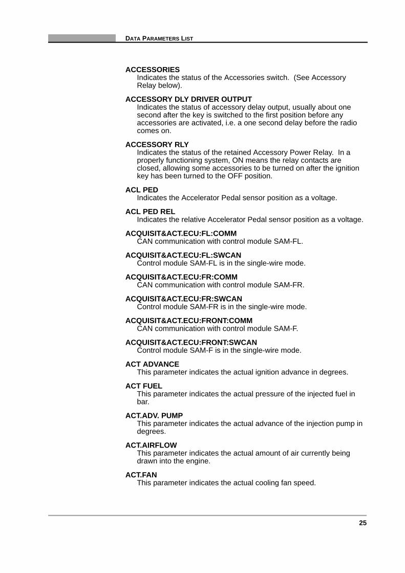
ACCESSORIESIndicates the status of the Accessories switch. (See Accessory Relay below).
ACCESSORY DLY DRIVER OUTPUTIndicates the status of accessory delay output, usually about one second after the key is switched to the first position before any accessories are activated, i.e. a one second delay before the radio comes on.
ACCESSORY RLYIndicates the status of the retained Accessory Power Relay. In a properly functioning system, ON means the relay contacts are closed, allowing some accessories to be turned on after the ignition key has been turned to the OFF position.
ACL PEDIndicates the Accelerator Pedal sensor position as a voltage.
ACL PED RELIndicates the relative Accelerator Pedal sensor position as a voltage.
ACQUISIT&ACT.ECU:FL:COMMCAN communication with control module SAM-FL.
ACQUISIT&ACT.ECU:FL:SWCANControl module SAM-FL is in the single-wire mode.
ACQUISIT&ACT.ECU:FR:COMMCAN communication with control module SAM-FR.
ACQUISIT&ACT.ECU:FR:SWCANControl module SAM-FR is in the single-wire mode.
ACQUISIT&ACT.ECU:FRONT:COMMCAN communication with control module SAM-F.
ACQUISIT&ACT.ECU:FRONT:SWCANControl module SAM-F is in the single-wire mode.
ACT ADVANCEThis parameter indicates the actual ignition advance in degrees.
ACT FUELThis parameter indicates the actual pressure of the injected fuel in bar.
ACT.ADV. PUMPThis parameter indicates the actual advance of the injection pump in degrees.
ACT.AIRFLOWThis parameter indicates the actual amount of air currently being drawn into the engine.
ACT.FANThis parameter indicates the actual cooling fan speed.

26 Adaptors Overview & Data Parameters 2007-10
C H A P T E R 3 DATA PARAMETERS
ACT.FAN SPDThis parameter indicates the actual cooling fan speed.
ACT.FUEL QTYThis parameter indicates the actual fuel quantity injected every stroke.
ACT.INJ BGNThis parameter indicates the actual injection begin (advance) controlled by the ECU. The reading is in degrees of crank angle can + for BTDC or - for ATDC.
ACT.PRESThis parameter indicates the actual fuel pressure.
ACTIVATION DOWNGRADED MODEIndicates the status of the Activation Downgrade Mode.
ACTIVATION POWER-CONSUMERSIndicates the status of the Activation Power-consumers.
ACTIVE BODY CTRL SPORT SWN72s20 (ABC SPORT switch).
ACTUAL ADVANCE PUMPIndicates the actual advance of the injection pump in degrees.
ACTUAL AIR FLOWIndicates the actual amount of air currently being drawn into the engine.
ACTUAL CALCULATION TIMECurrent Calculation Time.
ACTUAL EGR LIFTING SENDERDisplays the EGR lifting sender position in mm.
ACTUAL ENGINE SPEEDIndicates the actual engine speed in 1/min.
ACTUAL FANIndicates the actual cooling fan speed as a percentage.
ACTUAL FAN SPEEDIndicates the actual cooling fan speed as a percentage.
ACTUAL FUEL AMOUNTIndicates the actual fuel amount injected every stroke.
ACTUAL FUEL PRESSUREIndicates the actual fuel pressure.
ACTUAL GEARDisplays the actual selected gear, P, N, D, R, 1, 2, 3, 4 or 5.
ACTUAL INJDisplays the actual fuel injected at the start of delivery in milligrams per stroke.

27
DATA PARAMETERS LIST
ACTUAL INJECT.QTY. PER STROKEDisplays the actual fuel quantity injected per stroke.
ACTUAL INJECTION BEGINIndicates the actual injection begin (advance) controlled by the ECU. The reading is in degrees of crank angle can + for BTDC or - for ATDC.
ACTUAL INTAKE AIR PRESSUREDisplays the actual air intake pressure in mbar.
ACTUAL PRESSURE DISTRIB.PIPEDisplays the actual pressure in the distribution pipe.
ACTUAL ROTORIndicates the actual rotor position in millimetres.
ACTUAL ROTOR POSITIONIndicates the actual rotor position.
ACTUAL SLIDE VALVE ACTUATORDisplays the slide valve actuator position in mm.
ACTUAL VACUUMIndicates the actual Vacuum measured.
ACTUAL VALUE POT.METER M16/X R XIndicates the actual position of the M16 potentiometers as a percentage. Used on drive-by-wire systems. See explanation ACTUAL VALUE POT.METER below for more information.
ACTUAL VALUE POT.METER POWER FAULTIndicates if there is a power fault on the Actual Valve POT.METER.
ACTUAL VALUE POT.METER VOLTAGEThe HFM system does not use a drive by wire electronic throttle actuator. Instead, it uses a mechanical throttle linkage linked to an electronic actuator located at the throttle body. The actuator has an integral clutch mechanism that overrides the mechanical linkage under certain conditions. The system is used to control idle, cruise control and Accelerator Slip Regulation controlled by the EA/CC/ ISC module. The voltage range varies depending on operating conditions.
ACTUAT.MODEIndicates the status of the Actuator mode.
ACTUATORIndicates the status of the actuator.
ACTUATOR ACT.VALUE POT.METER RXThis drive by wire system has no mechanical throttle linkage. An electronic actuator controls the throttle valve under different operating conditions to regulate idle speed, cruise control operation, driving on the basis of accelerator position, traction control (Acceleration Slip Regulation), Electronic Stability Program (ESP) and emergency running. The position of the accelerator pedal is detected by two potentiometers that transmit input signals to the

28 Adaptors Overview & Data Parameters 2007-10
C H A P T E R 3 DATA PARAMETERS
ECU. Based on these signals, the ECU in turn controls the electronic throttle actuator. One potentiometer is in the pedal value sensor and the other one is in the electronic actuator. The potentiometer in the electronic throttle actuator supplies a reference value for a plausibility check. In an emergency, if one potentiometer fails, the system switches over to the second one. A quick plausibility check is to add both actuator signal readings (R1 and R2 or SIGNAL 1 and SIGNAL 2) together at various throttle positions. They should always add up the same value, usually between 4.5 to 4.9 V.
ACTUATOR DE-ENERGIZEDIndicates whether the actuator is de-energised or not.
ACTUATOR OUTPUT VALUEIs the count value of the stepper motor type electronic throttle actuator.
ACTUATOR RELAYIndicates the status of the actuator relay.
ACTUATOR RELAY CONTROLIndicates the status of the Actuator Relay Control.
ACTUATOR SIGNAL XThis drive by wire system has no mechanical throttle linkage. An electronic actuator controls the throttle valve under different operating conditions to regulate idle speed, cruise control operation, driving on the basis of accelerator position, traction control (Acceleration Slip Regulation), Electronic Stability Program (ESP) and emergency running. The position of the accelerator pedal is detected by two potentiometers that transmit input signals to the ECU. Based on these signals, the ECU in turn controls the electronic throttle actuator. One potentiometer is in the pedal value sensor and the other one is in the electronic actuator. The potentiometer in the electronic throttle actuator supplies a reference value for a plausibility check. In an emergency, if one potentiometer fails, the system switches over to the second one. A quick plausibility check is to add both actuator signal readings (R1 and R2 or SIGNAL 1 and SIGNAL 2) together at various throttle positions. They should always add up the same value, usually between 4.5 to 4.9 V.
ADAPT LOWER ELECTRICAL STOPThis parameter indicates the voltage of the lower adaptive throttle valve electrical stop.
ADAPT LOWER MECHANICAL STOPThis parameter indicates the voltage of the lower adaptive throttle valve mechanical stop.
ADAPT. RANGE X GEAR, X000-X000 (rpm)Indicates if the engine and transmission controls are adapting together for specific conditions.

29
DATA PARAMETERS LIST
ADAPTATIONThe Adaptation value represents the operation and long-term correction of the fuel metering on a fuel-injected engine. The Adaptation value indicates whether the ECU is commanding a rich or a lean mixture.
ADAPTATION ACCEL PED POSThis parameter indicates the adaptive accelerator pedal position in degrees.
ADAPTATION BOOST PRESSUREIndicates the state of the boost pressure adaptation.
ADAPTATION CELLFor some vehicles, Adaptation is divided into a number of cells. The cells are arranged in a theoretical grid, five high and five wide. Width represents engine speed from low to high. Any combination of engine load and speed will fit into one of the cells in the theoretical grid. The ADAPTATION CELL parameter indicates which cell the engine is operating in at the moment.
ADAPTATION CELL CONTINUThe Adaptation Cell Continue carries out the mixture correction at idle or partial load conditions, but only if the O2 Integrator has deviated for an extended period of time from the ideal air/fuel ratio and the full load enrichment is ON.
ADAPTATION FILTERIndicates the state of the filter adaptation.
ADAPTATION FUEL PRESSUREIndicates the state of the fuel pressure adaptation.
ADAPTATION IGNITIONIndicates the state of the ignition adaptation.
ADAPTATION INJECTOR XIndicates the state of the injector adaptation.
ADAPTATION LOADIndicates the state of the load adaptation.
ADAPTATION MAPIndicates the state of the map adaptation.
ADAPTATION MIXTURE(ADD)This parameter represents the operation and short term correction to the fuel mixture. ADD means adding or subtracting equal amounts of fuel to every fuel block cell regardless of the pre-programmed base injection pulse value. It works very effectively for idle mixture related problems, but its effect is minimal at the higher engine speeds. For example, vacuum leaks greatly affect fuel mixture at idle but become less severe at higher rpm. The important distinction here is that the amount of fuel correction is not dependent upon the original base in each fuel memory cell.

30 Adaptors Overview & Data Parameters 2007-10
C H A P T E R 3 DATA PARAMETERS
ADAPTATION MIXTURE(MUL)This parameter represents the operation and short term correction to the fuel mixture. MUL means multiplying or taking the pre-programmed cell base value and multiplying that number by either a correction factor or percent. Here, the correction amount increased or decreased in each memory block cell is dependent on each cell’s base injection pulse. This form of adaptation is required to compensate for fuel control type problems that get worse with increased engine speed.
ADAPTATION POSITION XThis parameter indicates the specified Adaptation Position if the engine is adapting for specific conditions.
ADAPTATION PUMPIndicates the state of the pump adaptation.
ADAPTATION STATUSThis parameter indicates the Adaptation Status if the engine is adapting for specific conditions.
ADAPTATION THROTTLE ADJUSTERThis parameter displays the current throttle adjuster mode and can display idling or part throttle.
ADAPTATION THROTTLE VALVEThis parameter indicates the adaptive throttle valve position in degrees.
ADAPTATION TORQUEDisplays the adaptation torque.
ADAPTATION TORQUE DEVIATIONDisplays the adaptation torque deviation.
ADAPTATION VALUE CANP VALVE XThis parameter indicates the specified CANP Adaptation Valve value if the engine is adapting for specific conditions.
ADAPTATION VALUE O2This parameter is the learning value for the O2 Sensor when the engine is idling.
ADAPTATION VALVE XThis parameter indicates the specified Adaptation Valve angle if the engine is adapting for specific conditions.
ADAPTATION WASTE GATEThe ADAPTATION WASTEGATE is a learned parameter and measured in steps.
ADDITIONAL COOLANT PUMPThis parameter indicates the status of the Additional Coolant Pump.
ADDITIVE AMOUNTIndicates the amount of additive supplied in grams.

31
DATA PARAMETERS LIST
ADDITIVE MINIMUM LEVEL REACHEDIndicates that the minimum level for the additive is reached. (i.e. Less than 0.2 litres).
ADJ.MOTOR,VERTICAL-A67m1A67m1 (Vertical adjustment motor).
ADJUST. CAMSHAFT TIMING SOLENOIDCamshaft timing is adjustable and indicates the state of the camshaft timing solenoid. When the display reads ON, the solenoid is energized and when the display reads OFF it is not. With the solenoid activated camshaft timing is advanced and the display reads ON or OFF at different speeds. Reads OFF in the full retard position and ON in the full advance position. Solenoid should be OFF at speeds below 2000 rpm, ON at speeds between 2000 rpm and 4300 rpm and OFF at speeds over 4300 rpm.
ADR ACTIVEIndicates whether the ADR system is active or not.
ADR RPM ADJUSTMENTIndicates whether the ADR rpm adjustment is on or off.
ADVANCEThis parameter indicates the output signal applied by the ECU to the injection begin advance valve.
ADVANCE INDUCTANCE TIMEIndicates the Timing Advance Inductance Time.
ADVANCE SOL.VALVE COMMANDIndicates the status of the Timing Advance Solenoid Valve Command.
ADVANCE SOL.VALVE OUTPUTIndicates the Timing Advance Solenoid Valve Output.
ADVANCE(ACTUAL)Indicates the Actual Timing Advance.
ADVANCE(DESIRED)Indicates the Desired Timing Advance.
AFTERGLOWThis is the indication when the glow system is in afterglow or not.
AFTER-SALESNo information available at this time.
AFTER-START ENRICHMENTIndicates if the ECU is providing a rich fuel mixture after a cold start. The display reads ON with fuel enrichment at cold start, then switches to OFF once the engine warms up.
AIR CHARGEAIR CHARGE temperature (ACT) supplied to the PCM by the intake air temperature sensor. The ACT is a thermistor typically installed in the air cleaner. A 5-volt reference signal is applied to the ACT. As

32 Adaptors Overview & Data Parameters 2007-10
C H A P T E R 3 DATA PARAMETERS
temperature increases, sensor resistance decreases, providing the AIR CHARGE voltage signal to the PCM. The PCM converts ACT voltage signals to temperature readings.
AIR CLEANER PRESS.SNS,L.BANKB28/4 (Pressure sensor downstream of air cleaner, left cylinder bank) (hPa).
AIR CLEANER PRESS.SNS,R.BANKB28/5 (Pressure sensor downstream of air cleaner, right cylinder bank) (hPa).
AIR CONDITIONINGIndicates the status of the air conditioning system.
AIR CONTROL SOLENOIDIndicates the status of the Air Control Solenoid.
AIR DIFFUSER ABOVEThis parameter indicates the status of the upper Air Diffuser.
AIR DIFFUSER BELOWThis parameter indicates the status of the lower Air Diffuser.
AIR DIFFUSER MIDDLEThis parameter indicates the status of the middle Air Diffuser.
AIR DISTR.ACT.MOTOR,UP/DOWNM16/22 (Up/down air distribution actuator motor) (%).
AIR DISTRIBUTION SWITCHThis parameter indicated the state of the Air Distribution switch.
AIR DISTRIBUTION VALVEThis parameter indicates the position of the Air Distribution valve.
AIR DIVERT VALVEThis parameter reads ON when the air divert solenoid is ON and air bypass voltage is low and OFF when the solenoid is off and air bypass voltage is high. The solenoid controls a vacuum signal to the air divert valve. When the air divert system is activated, air is routed upstream.
AIR FLAP SWITCHOVER ANGLEIndicates the opening of the air flap in degrees.
AIR FLOW LOOP DIFFERENCEIndicates the Air Flow Loop Difference.
AIR FLOW SENSOR SUPPLYIndicates the Air Flow Sensor supply voltage.
AIR FLOW SUPPLYThis parameter is the actual voltage being read by the airflow sensor. This voltage is used by the ECU to calculate the amount of air being drawn into the engine.

33
DATA PARAMETERS LIST
AIR FLOW(ACTUAL)Indicates the Actual Air Flow.
AIR FLOW(DESIRED)Indicates the Desired Air Flow.
AIR FLOW(ESTIMATED)Indicates the Estimated Air Flow.
AIR FUEL RATIOOn some 1987 and later fuel-injected vehicles, the ECU calculates the desired air-fuel ratio during closed-loop operation. This is not a measured value, but the calculated value that the ECU wants to be delivered based on its sensor input signals. A lower number indicates a rich air-fuel ratio commanded for engine start-up. A higher number indicates a leaner ratio.
AIR LOGIC CHAINIndicates the status of the air logic chain.
AIR MASSThe ECU generates this parameter based on the input signal from the mass airflow sensor. The reading indicates the mass of the intake air charge as kilograms per hour, (kg/h) or in milligrams per stroke, (mg/S). Normal idle values vary by system and by engine.
AIR PUMPIndicates the state of the secondary air pump. The display reads YES or ON when the pump is activated and reads NO or OFF when the pump is off. Secondary air is pumped into exhaust system to reduce emissions under certain operating conditions. On HFM systems the pump should be on (YES) when engine temperature is below 4 °C, (40 °F).
AIR PUMP ACTIVATIONIndicates the status of the air pump.
AIR PUMP RELAYIndicates the status of the Air Pump Relay. When the relay is on the secondary air pump is active.
AIR PUMP SWITCHOVER VALVEIndicates whether the air pump switch-over valve is open or closed.
AIR PUMP SWITCHOVER VALVE, LEFTIndicates whether the left air pump switch-over valve is open or closed.
AIR PUMP SWITCHOVER VALVE, RIGHTIndicates whether the right air pump switch-over valve is open or closed.
AIR SUCTION TESTIndicates whether the air suction test has passed or failed.
AIR SUSP AT ACCURATE TRIMNo information available at this time.
34 Adaptors Overview & Data Parameters 2007-10
C H A P T E R 3 DATA PARAMETERS
AIR SUSP INHIBIT SWIndicates position of air suspension inhibit switch, ON/OFF.
AIR TEMPERATUREIndicates the Air Temperature.
AIR TEMPERATURE SENSORIndicates the Air Temperature Sensor voltage.
AIR TEMPERATURE TURBOIndicates the temperature of the air when leaving the turbocharger.
AIR TEMPERATURE:CORRECTEDIndicates the Corrected Air Temperature.
AIR/FUEL O2 SENSOR DATAIndicates if there is valid data coming from the air/fuel oxygen sensor.
AIR/FUEL RATIO TEST BANK XIndicates whether the air/fuel ratio test has passed or failed.
AIR/FUEL RATIO(BK1-SNSX)Indicates the Air/Fuel Ratio from Bank 1 Sensor x, where x = 1 or 2.
AIR-BAGIndicates the status of the Air-bag lamp.
AIRBAG CHIMEIndicates whether the Airbag Chime is switched on or off.
AIRBAG DEPLOYM.STATUS,DRIVERIndicates the Drivers Airbag Deployment status.
AIRBAG LOCKING BY KEY,PASS.Indicates whether the Airbag Locking by key has Passed or not.
AIRBAG LOCKING TYPE,PASS.Indicates whether the Airbag Locking Type has Passed or not.
AIRBAG WARNING LAMP & CHIMEIndicates the status of the Airbag Warning Lamp and Chime.
AIRBAG:COMMCAN communication with control module Airbag.
AIRBAG:CRASH SIGNALCrash signal from control module Airbag in the crash memory.
AIRBAG:SWCANControl module Airbag is in the single-wire mode.
AIRCOAir conditioning.
AIRCO AUTHORISATIONIndicates the status of the Airco Authorisation.

35
DATA PARAMETERS LIST
AIRCO COMPRESSORThis parameter indicates whether the ECU has turned the A/C compressor ON or OFF.
AIRCO COMPRESSOR CLUTCHThis parameter is a feedback signal from the A/C compressor clutch or relay. When it is ON, the clutch is engaged, when it is OFF, the clutch is disengaged. The ECU uses this signal primarily to control the idle speed.
AIRCO COMPRESSOR RELAYIndicates the status of the Airco Compressor Relay.
AIRCO COMPRESSOR STATUSThis parameter indicates the status of the A/C Compressor.
AIRCO COMPRESSOR-A9:[%]On/off ratio of component A9 (AC compressor) (%).
AIRCO CUT-OFFThis parameter indicates that the ECU has commanded the A/C compressor to interrupt its operation. i.e. when wide open throttle is indicated the ECU will suspend the A/C compressor operation.
AIRCO CUT-OFF DURING ACCELERATIONIndicates that the ECU has commanded the A/C compressor to interrupt its operation during acceleration. The ECU will suspend the A/C compressor operation.
AIRCO CUT-OFF DURING OVER REVVINGIndicates that the ECU has commanded the A/C compressor to interrupt its operation during over revving. The ECU will suspend the A/C compressor operation.
AIRCO ECU BUTTON-N22:COMMCAN communication with control module N22 (AAC pushbutton control module).
AIRCO ECU,REAR-N22/4:COMMCAN communication with control module N22/4 (Rear air conditioning control module).
AIRCO ECU-N19:AIRCO REQ.AC request from component N19 (Air conditioning control module).
AIRCO ENABLEThis parameter indicates whether or not the ECU allows the A/C to be used or not.
AIRCO HEAT EXCH.TEMP SNS,RLB10/9 (Left rear air conditioning heat exchanger temperature sensor) (°C).
AIRCO HEAT EXCH.TEMP SNS,RRB10/10 (Right rear air conditioning heat exchanger temperature sensor) (°C).

36 Adaptors Overview & Data Parameters 2007-10
C H A P T E R 3 DATA PARAMETERS
AIRCO INFO SWITCHIndicates the position of the Airco Information Switch.
AIRCO INFORMATION SWITCHIndicates the status of the Airco Information Switch.
AIRCO LOAD SWITCHIndicates the position of the Air-Conditioning Load Switch. ON means that the A/C system has been turned on and is under load.
AIRCO MODEThis parameter displays if the air-conditioning system is set in the HIGH or LOW mode.
AIRCO MODE/REAR HEATER SWITCHThis parameter indicates the status of the A/C Mode rear heater switch.
AIRCO PRESENTThis parameter indicates that the ECU has detected whether or not an A/C system is present.
AIRCO PRESSUREThis parameter indicates the pressure from the A/C Pressure Sensor.
AIRCO PRESSURE PWMDisplays the current pressure in the A/C system under present operating conditions. If the A/C Pressure goes too high or too low the A/C system will be switched off.
AIRCO PRESSURE SENSORThis parameter indicates the voltage from the A/C Pressure Sensor.
AIRCO PREVENTION CONTROLIndicates the status of the Airco Prevention Control.
AIRCO READINESSThis parameter checks if the A/C system is ready to be used, if A/C is fitted and no defects are found in the system, the reading will be YES, if the vehicle does not have A/C fitted or a fault in the system or wiring is found, the reading will be NO.
AIRCO RELAYThis parameter indicates whether the ECU has turned the A/C relay ON or OFF.
AIRCO REQUESTThis parameter indicates whether or not the ECU issued a request to turn the A/C on.
AIRCO SOLENOIDIndicates the status of the Air-Conditioning Solenoid.
AIRCO SWITCHThis parameter informs the ECU whether the A/C switch is in the ON or OFF position.

37
DATA PARAMETERS LIST
AIRCO SWITCH ONThis parameter informs the ECU whether the A/C switch is ON.
AIRCO SWITCH-OFF REQUESTThis parameter is an ECU command signal for the A/C system. When it is on, the ECU will force the A/C system to disengage operation.
AIRCO/FAN CONTROL STRATEGYIndicates the status of the Airco/Fan Control Strategy.
AIRCO-COMPR/FAN CONTROLIndicates the status of the Airco Compressor Fan Control.
AIRCONDITIONINGAir conditioning.
AIRCONDITIONING ACTIVEIndicates the position of the air conditioning cycle switch. ON means that the A/C switch on the instrument panel has been turned on or that the ECU has commanded the A/C system to turn on. In some cases, the A/C compressor may not turn on even though the switch is closed. Several other switch or sensor signals may prevent the ECU from engaging the A/C compressor clutch.
AIRCONDITIONING MONITORIndicates the status of the air-conditioning monitor.
AIRCONDITIONING SIGNALIndicates whether an air-condition signal is present or not.
AIRCONDITIONING:REAR:COMMCAN communication with control module REAR AC.
AIRCONDITIONING:REAR:SWCANControl module REAR AC is in the single-wire mode.
AIRFLOWThis parameter indicates the amount of air currently being drawn into the engine.
AIRFLOW SENSORThis parameter indicates the voltage from the Airflow Sensor.
AIRFLOW SENSOR GROUNDThis parameter indicates whether the ECU has determined that a fault has occurred on the Airflow Sensor ground wire.
AIRFLOW SENSOR X BANK XIndicates the voltage of the airflow sensor x on bank x.
ALARMAlarm.
ALARM SIGNAL HORN-H3H3 (Alarm signal horn).

38 Adaptors Overview & Data Parameters 2007-10
C H A P T E R 3 DATA PARAMETERS
ALARM SIGNAL TO ECU E-CALLAlarm signal to control module E-call.
ALARM:ACTIVATION XAlarm activation, where X = 2 to 10.
ALARM:LAST ACTIVATIONLast alarm activation.
ALL ACTIVITY MODULE:CAN MSGCAN message from control module AAM regarding low beam status.
ALTERNATOR DEFECTThis parameter indicates if a fault or defect has occurred in the alternator.
ALTERNATOR LOADThis parameter displays the current alternator load.
ALTERNATOR OKThis parameter shows whether the ECU has recognised a charging voltage, if the reading is YES, then Adaptation (adaptive learn) can take place. If the reading is NO, then the ECU will not re-learn any values.
ALTITUDE ADAPTATION FACTORThis parameter displays the correction factor for altitude and is applied to air intake and lambda values when driving in mountainous terrain.
ALTITUDE FACTORDisplays the altitude correction factor as a percentage.
AMBIENT AIR TEMP(UNFILTERED)Displays the Unfiltered Ambient Temperature.
AMBIENT LIGHT,SENSOR VALUESensor value of ambient light (%).
AMBIENT PRESSUREThe ECU calculates the ambient pressure based on the input signal from the Barometric Pressure (BARO) Sensor.
AMBIENT TEMP SNSRDisplays the voltage from the ambient temperature sensor.
AMBIENT TEMP.DISPLAY:SNSB14 (Ambient temperature display temperature sensor) (°C).
AMBIENT TEMPERATUREThis parameter displays the ambient temperature outside the vehicle.
AMOUNT BEFORE FUEL PUMPThis parameter indicates the amount of fuel before the fuel pump.
ANCILLARY DESIRED ENGINE SPEEDNo information available at this time.

39
DATA PARAMETERS LIST
ANGLE VEH.-TARGET DETECTEDAngle of vehicle to target object detected (Grad).
ANTI-CYCLIC ADAPTATION XIndicates the Anti-cyclic Adaptation, where x = 1, 2 or 3.
ANTI-PERCOLAT.RELAY COMMANDIndicates the status of the Anti-percolation Relay Command.
ANTI-ROLL&VARIO ROOF:COMMCAN communication with control module RVC.
ANTI-SKIDIndicates whether an Anti-Skid system in present or not.
ANTI-SKID DISABLE SWITCHIndicates the status of the Anti-Skid Disable Switch.
ANTI-THEFTThis parameter indicates that the anti-theft device built into the ECU is active (ON) or inactive (OFF). When the Anti-theft device is active the engine should not start.
ANTI-THEFT DEVICEThis parameter indicates that the anti-theft device built into the ECU is active (ON) or inactive (OFF). When the Anti-theft device is active the engine should not start.
ANTI-THEFT SYSTEM:ARMEDATA armed.
ANTI-THFT ALARM C.CONSOLES62/8 (ATA centre console compartment switch).
ANTI-THFT ALARM STATUS INDICS97/6e3 (ATA status indicator).
APP CAL POSITIONDisplays the Calculated Accelerator Pedal position in percentage.
ARMREST COMP.LIGHTE36 (Armrest storage compartment lighting).
ARMREST COMP.LIGHT:ACT.POWERCurrent power of component E36 (Armrest storage compartment lighting) (mA).
ASC DISABLEDThis parameter indicates whether the Anti Spin Control is disabled or not.
ASC INTERVENTThis parameter indicates that the Anti Spin Control is required to be activated for the current driving conditions.
ASC PRESENTThis parameter indicates that the Anti Spin Control system is installed.

40 Adaptors Overview & Data Parameters 2007-10
C H A P T E R 3 DATA PARAMETERS
ASC REQUEST ACKNOWLEDGEThis parameter is a request acknowledgement from the ECU for the Anti Spin Control system to be activated.
ASC STATUSIndicates whether the Anti Spin Control system is active or inactive.
ASC TORQUE DECREASEThis parameter indicates that the Anti Spin Control system is reducing the torque.
ASC TORQUE DECREASE REQUESTThis parameter is a request from the ECU for the Anti Spin Control system to reduce the torque.
ASC TORQUE INCREASEThis parameter indicates that the Anti Spin Control system is increasing the torque.
ASC,REQ.TORQUE RAISE AT WHEELSThis parameter is a request from the ECU for the Anti Spin Control system to increase the torque at the wheels.
ASC,REQ.TORQUE REDUCT.AT WHEELSThis parameter is a request from the ECU for the Anti Spin Control system to reduce the torque at the wheels.
ASC/DSC SWITCHThis parameter indicates the position of the Anti Spin Control (ASC) or Dynamic Stability Control (DSC) switch.
ASR ACTIVEIndicates whether the ASR system is active.
ASR PRESENTThis parameter indicates that the ECU has detected whether or not an ASR is present.
ASR/MSR REQUESTIndicates that the engine is reaching the torque value requested by the ASR/MSR device.
ASR/TC DISABLE SWITCHIndicates whether or not the ASR/TC disable switch is pressed.
ATA HOOD SWS62 (ATA hood switch).
ATF COUNTERCondition counter for Automatic Transmission Fluid calculated from the number of starts/time, etc.
ATF TEMPERATUREAutomatic transmission fluid temperature is an analogue parameter supplied to the ECU by the automatic transmission fluid temperature sensor. The automatic transmission fluid temperature sensor is a thermistor installed in the automatic transmission fluid. At low temperatures the resistance is high and a high voltage signal is

41
DATA PARAMETERS LIST
produced. As temperature increases, sensor resistance decreases, providing a decreasing automatic transmission fluid voltage signal to the ECU. This parameter can also be displayed as a voltage.
ATF TEMPERATURE HIGHIndicates if the automatic transmission fluid temperature is too high.
AUC FUNCTIONThis parameter indicates whether the AUC (Automatic Recirculation Control) Function is active or not.
AUC SENSORThis parameter indicates the voltage from the AUC (Automatic Recirculation Control) Sensor.
AUDIO SYSTEM SIGNALIndicates the status of the Audio System signal.
AUDIO VOLUME - SWIndicates the status of the audio volume decrease control steering wheel switch.
AUDIO VOLUME + SWIndicates the status of the audio volume increase control steering wheel switch.
AUTO RIDE CTRL STATUSNo information available at this time.
AUTO SWITCHThis parameter indicates the status of the automatic air conditioning switch.
AUTOM.LOWERING SW:FRONT RI.Switch for automatic lowering at front right.
AUTOM.MIRROR DIMMING BLOCKEDAutomatic mirror dimming inhibited.
AUTOMATIC AIRCO:COMMCAN communication with control module AAC.
AUTOMATIC AIRCO:SWCANControl module AAC is in the single-wire mode.
AUTOMATIC BLOWERThis parameter indicates whether the Automatic Blower is ON or OFF.
AUTOMATIC DRIVING LAMPSAutomatic driving lamps.
AUTOMATIC LOWERING SW:FLSwitch for automatic lowering at front left.
AUTOMATIC TRAMSMISSIONIndicates whether an Automatic Transmission system is present or not.

42 Adaptors Overview & Data Parameters 2007-10
C H A P T E R 3 DATA PARAMETERS
AUTOMATIC TRANSMISSION VALVE XIndicates the status of the specified transmission valve.
AUXILIARY HEAT REQUESTEDThis parameter indicates if Auxiliary Heat is requested or not.
AUXILIARY HEATER REQUESTEDThis parameter indicates whether an auxiliary heater is ON or OFF.
AVERAGE SHORT TERM MIXTURE CORR.This parameter indicates the Average Short Term Mixture Correction.
AXLE RATENo information available at this time.
3.2.3 BB ACT.MODE
Indicates the status of the “B” Actuator Mode.
BACK PRESSURE VALVE MOTORThis parameter indicates the Back Pressure Valve motor duty cycle as a percentage.
BACKUP LAMP SWITCHIndicates whether the backup (reversing) lamp switch is either on or off.
BAND SWIndicates the status of the Radio Band switch.
BANK X CRANKSHAFT SEGM.X ADAPTThis parameter measures the amount of ignition advance or retard required to compensate for ignition misfire. The acceleration of the crankshaft is checked by firing the relevant cylinder in the specified cylinder bank, the respective acceleration (change in rotation speed) of the cylinders is then compared with each other. The misfire detection functions across the entire engine speed range above 15 % of engine load.
BANK X-YBANK X-Y refers to cylinder bank 1 or cylinder bank 2 respectively and Y refers to actual cylinder number.
BAROThis parameter indicates the Barometric pressure in mbar or bar as calculated by the ECU from the voltage supplied by the Barometric Pressure Sensor. Some systems do not have a BARO sensor, but the ECU calculates it by sampling the MAP sensor voltage signal with the ignition key on and the engine off, just before cranking. This parameter can also indicate the voltage read by the ECU from the Barometric Pressure Sensor.

43
DATA PARAMETERS LIST
BARO PRES SENSThe PCM calculates a barometric pressure reading from the barometric pressure (BARO) sensor frequency signal. In some PCMs the readings can also be displayed as a frequency measurement in Hz.
BAROMETRIC PRESSUREThis parameter indicates the Barometric pressure in mbar or bar as calculated by the ECU from the voltage supplied by the Barometric Pressure Sensor. Some systems do not have a BARO sensor, but the ECU calculates it by sampling the MAP sensor voltage signal with the ignition key on and the engine off, just before cranking. This parameter can also indicate the voltage read by the ECU from the Barometric Pressure Sensor.
BAROMETRIC PRESSURE SENSORThis parameter indicates the voltage from the Barometric Pressure Sensor.
BAS DIAPHRAGM TRAVEL SNSA7/7b1 (BAS diaphragm travel sensor) (mm).
BAS RELEASE SW,NC CONTACTComponent A7/7s1 (BAS release switch), NC contact.
BAS RELEASE SW,NO CONTACTComponent A7/7s1 (BAS release switch), NO contact.
BASE VALUE THROTTLE POS SENSORThis parameter indicates the stored base value for the throttle value potentiometer position when throttle valve is fully closed. The value is determined when base settings are activated with throttle closed.
BASIC INJECTION DURATIONDisplays the length of time in milliseconds (ms) that the ECU commands the fuel injectors to remain on. Normal range is approximately 3 to 5 ms at idle.
BATTThis parameter indicates the voltage of the vehicle’s battery measured by the ECU. The ECU uses this voltage to correct several output signals. It is used for controlling the injection time, idle speed control and ignition coil loading times.
BATTERYThis parameter indicates the voltage of the vehicle’s battery measured by the ECU. The ECU uses this voltage to correct several output signals. It is used for controlling the injection time, idle speed control and ignition coil loading times.
BATTERY SAVER DRIVERIndicates the GEM command status for the battery saver relay solenoid. When the system functions properly, ON means the contacts of the relay are closed.
BATTERY VOLTAGE TOO LOWIndicates if the battery voltages is too low.

44 Adaptors Overview & Data Parameters 2007-10
C H A P T E R 3 DATA PARAMETERS
BELTMINDER STATUS,DRIVERIndicates the Drivers Seatbelt Minder status.
BELTMINDER STATUS,PASSENGERIndicates Passenger Seatbelt Minder status.
BLENDING AIR FLAP POS.SNSM16/8b1 (Blending air flap position sensor).
BLOCK IDENTITYThis parameter is found on older vehicles. The O2 Block Learn Multiplier number represents the operation and long-term correction of the fuel metering on a fuel-injected engine. The block learn number indicates whether the ECU is commanding a rich or a lean mixture.
BLOWERThis parameter indicates the Blower signal as a percentage.
BLOWER CONTROLThis parameter indicates the Blower Control voltage.
BLOWER LOCK ROTORIndicates the status of the Blower Lock Rotor.
BLOWER MOTORIndicates whether the blower motor is on or off.
BLOWER POTENTIOMETERThis parameter displays the position of the Blower Potentiometer as a percentage.
BLOWER REGULATIONThis parameter indicates the Blower Regulation.
BLOWER,INTERIOR TEMP.SNSBlower of interior temperature sensor.
BODY ACCEL.SENSOR,FL-B24/3B24/3 (Left front body acceleration sensor) (mV).
BODY ACCEL.SENSOR,FR-B24/4B24/4 (right front body acceleration sensor) (mV).
BODY ACCEL.SENSOR,REAR LEFTB24/5 (Left rear body acceleration sensor) (V).
BODY ACCEL.SENSOR,REAR RIGHTB24/6 (right rear body acceleration sensor) (mV).
BOILER RELAY COMMANDIndicates the status of the Boiler Relay command.
BOOSTThis parameter displays the current boost pressure in the intake manifold under present operating conditions. Value is an absolute pressure or it may indicate a percentage of the maximum boost pressure.

45
DATA PARAMETERS LIST
BOOST COMMANDDisplays the current pressure in the intake manifold under present operating conditions. Value is in bar and will be an absolute pressure.
BOOST CORIndicates the state of the boost adaptation.
BOOST PRESS.LOOP DIFFERENCEIndicates the Boost Pressure loop Difference.
BOOST PRESSUREThis parameter displays the current pressure in the intake manifold under present operating conditions. Value is in millibars and will be an absolute pressure.
BOOST PRESSURE ACTUATORDisplays the position of the boost pressure actuator as a percentage.
BOOST PRESSURE CONTROLIndicates whether the boost pressure control is on or off.
BOOST PRESSURE(DESIRED)This parameter is the calculated desired boost pressure in mbar.
BOOST PRESSURE:SPECIFIEDSpecified boost pressure (hPa).
BOOST SENSOR SUPPLYThis parameter displays the actual input voltage signal from the boost pressure sensor.
BRACKETDisplays the resistance of the Airbag mounting bracket to ground.
BRAKE AND ABS LAMP STATEIndicates the status of the Brake and ABS Lamp.
BRAKE FLUID INDICATOR SW-S11S11 (Brake fluid indicator switch).
BRAKE FLUID LEVEL LOWIndicates whether the Brake Fluid Level is low.
BRAKE FLUID PRESSUREIndicates the Brake Fluid Pressure.
BRAKE LAMPIndicates the status of the Brake Lamp.
BRAKE LAMP SWITCHIndicates the status of the Brake Lamp Switch.
BRAKE LAMP SWITCH VIA CANIndicates whether the parking brake lamp switch (via the CAN bus) is on or off.
46 Adaptors Overview & Data Parameters 2007-10
C H A P T E R 3 DATA PARAMETERS
BRAKE LIGHTThis parameter indicates that the ECU has detected if the brake pedal has been pressed. This parameter frequently only functions when Cruise Control is present. Also it can be used on diesel vehicles.
BRAKE LIGHT SWS9/1 (Stop lamp switch).
BRAKE LIGHT SW OUTPUT ECUStop lamp switch output at control unit A7/3n1 (SBC control module).
BRAKE LIGHT SW,NC CONTACTComponent S9/1 (Stop lamp switch), NC contact.
BRAKE LIGHT SW,NO CONTACTComponent S9/1 (Stop lamp switch), NO contact.
BRAKE LIGHT SWITCHThis parameter indicates that the ECU has detected that the brake light switch is closed or open.
BRAKE ON OFFIndicates OFF when the brakes are not applied and ON when the brakes are applied.
BRAKE OPERATEDIndicates if the brake pedal has been pressed.
BRAKE PAD SENSOR,FL-S10/1S10/1 (Left front brake pad contact sensor).
BRAKE PAD SENSOR,FR-S10/2S10/2 (Right front brake pad contact sensor).
BRAKE PAD WEAR SW OKIndicates the status of the Brake Pad wear switch.
BRAKE PADS WORNIndicates whether the Brake Pads are worn.
BRAKE PEDALThis parameter indicates that the ECU has detected if the brake pedal has been pressed. This parameter frequently only functions when Cruise Control is present. Also it can be used on diesel vehicles.
BRAKE PEDAL POS/BRAKE SWIndicates the status of the Brake Pedal Position switch.
BRAKE PEDAL PRESSEDThis parameter indicates that the ECU has detected that the brake pedal has been pressed.
BRAKE PEDAL PRESSUREIndicates the pressure exerted by the driver measured by the relative sensor on the ABS ECU.

47
DATA PARAMETERS LIST
BRAKE PEDAL REDUNDANTIndicates whether the Brake Pedal is Redundant or not.
BRAKE PEDAL SWReads OFF when the brakes are not applied and ON when the brakes are applied. BOO = BRAKE ON/OFF Switch.
BRAKE PEDAL TRAVELIndicates the Brake Pedal Travel.
BRAKE PRESSURE APPLIEDIndicates whether the Brake Pressure Sensor is on or off. Used on diesel vehicles only.
BRAKE PRESSURE TRANSDUCER MAINIndicates the status of the Main Brake Pressure transducer.
BRAKE PRESSURE TRANSDUCER REDUNDANTIndicates the status of the Redundant Brake Pressure transducer.
BRAKE SIGNALThis parameter indicates whether there is a signal from the Brake Switch. When the parameter displays ON, the brake pedal is pressed and the Brake Switch is giving a signal. When it displays OFF, the brake pedal is released and the Brake Switch is not giving a signal.
BRAKE SWThis parameter indicates that the ECU has detected if the brake pedal has been pressed. This parameter frequently only functions when Cruise Control is present. Also it can be used on diesel vehicles.
BRAKE SW.INFORMATION(CAN)Indicates the status of the Brake Information Switch on a CAN system.
BRAKE SWITCHThis parameter indicates that the ECU has detected if the brake pedal has been pressed. This parameter frequently only functions when Cruise Control is present. Also it can be used on diesel vehicles.
BRAKE SWITCH 1This parameter indicates that the ECU has detected if the brake pedal has been pressed. This parameter frequently only functions when Cruise Control is present. Also it can be used on diesel vehicles.
BRAKE SWITCH X INFORMATIONIndicates the status of the Brake Information Switch x, where x = 1 or 2.
BRAKE SWITCH 2This brake switch backup signal indicates that the ECU has detected by a second switch if the brake pedal has been pressed. This parameter frequently only functions when Cruise Control is present. Also it can be used on diesel vehicles.

48 Adaptors Overview & Data Parameters 2007-10
C H A P T E R 3 DATA PARAMETERS
BRAKE SWITCH:CLOSING WIREIndicates the status of the Brake Switch Closing wire.
BRAKE SWITCH:CLOSUREIndicates whether the Brake Switch is Closed or not.
BRAKE TEST SWITCHBRAKE TEST SWITCH is a back-up to the brake switch. Depending on the wiring used in the vehicle the two parameters (BRAKE SWITCH) should be equal or the exact opposite of each other.
BRAKE TORQUEBrake torque (Nm).
BRAKE WARNING IND INPUTIndicates the status of the Brake Warning Indicator input.
BRAKE WARNING LAMP DRIVER OUTPUTIndicates the status of the brake lamp.
BRAKE WARNING LMP SHORT GNDIndicates that the brake warning light is shorted to ground.
BRAKES PR.Indicates the Brake Pressure.
BRAKING PRESSUREThis parameter indicates the brake pressure.
BRIEF SELF-ADAPTATIONIndicates whether or not the ECU is attempting to compensate for tolerances in the mixture by means of long term adaptation, or long term fuel trim (LTFT) adjustments. The display only reads ON when the ECU is making brief LTFT adjustments.
BUTTON FANFARE HORNS-S110s5 S110s5 (Fanfare horns pushbutton).
BUTTON FOR HORNS-S110/111s5S110s5 or S111s5 (pushbutton for fanfare horns).
BUTTON INSTANT HEATInstant heat pushbutton.
BUTTON INSTANT VENTILATIONInstant ventilation pushbutton.
BUTTON INTERIOR LIGHT:FLPushbutton for left front interior light.
BUTTON INTERIOR LIGHT:FRPushbutton for right front interior light.
BUTTON INTERIOR LIGHT:RLPushbutton for left rear interior light.
BUTTON INTERIOR LIGHT:RRPushbutton for right rear interior light.
49
DATA PARAMETERS LIST
BUTTON SYST.SELECTION&VCSS110s2 (System selection and VCS pushbutton).
BUTTONS ‘+’ & ‘-’ -S111s1S111s1 (pushbutton + and -, setting specific functions and volume control).
BUTTONS MULTIF.STEERINGWHL,RS111 (right multi function steering wheel pushbutton group).
BUZZER SIGN.TO INSTR.CLUSTERBuzzer signal to control module A1 (Instrument cluster).
3.2.4 CC/C ERROR
Indicates that a error has occurred in the Cruise Control System.
C/C PRESENTThis parameter indicates that the ECU has detected whether or not Cruise Control is present.
C/C SHUTOFF BY FUNCTION PROCCruise control shut off by function processor.
C/C SHUTOFF:BY BACK-UP ECUCruise control shut off by back-up processor.
C/C SHUTOFF:FUNC.PROCESSORCruise control shut off by function processor.
C/C STUTOFF BY BACK-UP PROCCruise control shut off by back-up processor.
C/C SW, STEERING COLUMN MODCruise control switch Steering column module.
C/C SWITCH:ACCELERATECruise control switch ‘accelerate’.
C/C SWITCH:DECELERATECruise control switch ‘decelerate’.
C/C SWITCH:OFFCruise control switch ‘off’.
C/C SWITCH:STORECruise control switch ‘store’.
CAL THR POSDisplays the Calibrated Throttle position as a percentage.
CALC ENGINE LOADIs calculated by the PCM based on engine speed (rpm), number of cylinders, airflow and cylinder air charge compared to the theoretical air charge that occurs at standard PCM temperature and pressure (volumetric efficiency). The resulting ratio — called engine load — is expressed as a percentage. A normal load at idle is between 20 and
50 Adaptors Overview & Data Parameters 2007-10
C H A P T E R 3 DATA PARAMETERS
40 %. During normal driving, load will be less than 80 %. On supercharged vehicles, or under hard acceleration in cold temperatures or high barometric pressure, load can exceed 100 %. CALC LOAD is the calculated load value from the ECU.
CALCULATED ENGINE SPEEDThis parameter displays the calculated engine speed in rpm.
CALIBR PEDALThis parameter indicates if the calibration of the throttle valve has been done correctly.
CALIBRATED THROTTLE POSITIONDisplays the Calibrated Throttle position as a percentage.
CALIBRATION RESULTIndicates the result of the system calibration.
CAM ADJThis parameter indicates that the ECU has activated the camshaft timing adjustments.
CAM/CRANKSHAFT SYNCHRON.Indicates the status of the Cam/Crankshaft Synchronisation.
CAMSHAFTThis parameter indicates whether or not the ECU has commanded the Camshaft Relay ON or OFF. It is used to change the timing of the inlet camshaft.
CAMSHAFT ADJUSTER MODEThis parameter indicates that the ECU has activated the camshaft timing adjustments.
CAMSHAFT ADJUSTMENTThe ECU uses this signal to the variable camshaft timing solenoid. If the display reads ON, the ECU is energizing the solenoid to advance camshaft timing. Typically, the display reads OFF at idle and switches on at 2000 rpm on M119.XXX and M120.XXX engines and 4000 rpm for all other engines.
CAMSHAFT ADJUSTMENT VALVE, LEFTIndicates whether the left camshaft adjustment valve is on or off.
CAMSHAFT ADJUSTMENT VALVE, RIGHTIndicates whether the right camshaft adjustment valve is on or off.
CAMSHAFT ADVANCEThis parameter displays the amount of camshaft adjustment commanded by the ECU, when active.
CAMSHAFT BANK XThis parameter displays the Camshaft position in degrees for the various cylinder banks.
CAMSHAFT CONTROLIndicates the status of the camshaft control system.
51
DATA PARAMETERS LIST
CAMSHAFT CONTROL LOGIC CHAINIndicates whether the camshaft control logic chain is active or not active.
CAMSHAFT HALL-EFFECT SENSORIndicates the state of the signal from camshaft position (CMP) sensor. The reading switches between 55 and AA depending on whether Hall-effect signal is High or Low. The value should be constantly switching whenever the engine is running and the frequency of the switching increases and decreases in proportion to engine speed. Be aware, readings may be outside the normal range when the engine is cranking.
CAMSHAFT HALL-SNS,LEFT BANKB6/2 (camshaft Hall sensor, left bank of cylinders).
CAMSHAFT HALL-SNS,RIGHT.BANKB6/3 (camshaft Hall sensor, right bank of cylinders).
CAMSHAFT OFFSETIndicates the Camshaft Offset.
CAMSHAFT OFFSET CONTROLIndicates the status of the Camshaft Offset Control.
CAMSHAFT POSITIONThis parameter displays the Camshaft position in degrees.
CAMSHAFT POSITION BANK XThis parameter displays the Camshaft position in degrees for the various cylinder banks.
CAMSHAFT POSITION,FRONT CYLIndicates the Camshaft Position for the front cylinder bank.
CAMSHAFT POSITION,REAR CYLIndicates the Camshaft Position for the rear cylinder bank.
CAMSHAFT REF. MARK SIGNALIndicates whether the camshaft reference mark signal is on or off.
CAMSHAFT SIGNAL, LEFT BANKIndicates whether there is a camshaft signal from the left bank.
CAMSHAFT SIGNAL, RIGHT BANKIndicates whether there is a camshaft signal from the right bank.
CAMSHAFT SOLENOIDThe ECU uses this signal to the variable camshaft timing solenoid. If the display reads ON, the ECU is energizing the solenoid to advance camshaft timing. Typically, the display reads OFF at idle and switches on at 2000 rpm on M119.XXX and M120.XXX engines and 4000 rpm for all other engines.
CAMSHAFT SPEEDIndicates the Camshaft Speed.
52 Adaptors Overview & Data Parameters 2007-10
C H A P T E R 3 DATA PARAMETERS
CAMSHAFT TIMINGThe ECU uses this signal to the variable camshaft timing solenoid. If the display reads ON, the ECU is energizing the solenoid to advance camshaft timing. Typically, the display reads OFF at idle and switches on at 2000 rpm on M119.XXX and M120.XXX engines and 4000 rpm for all other engines.
CAN DATA EXCHANGEIndicates whether the CAN bus data exchange signal is active or not active. The CAN bus is a broadcast type of bus. This means that all modules “hear” all transmissions. There is no way to send a message to just a specific module; all modules pick up all traffic. However, CAN hardware provides local filtering so each module reacts only to data whose identifiers are stored in its acceptance list. This very high frequency transmission requires a “Twisted Pair” of wires to address EMI concerns. Two wires also ensure communication if one wire is damaged and provide the ability to recognize a CAN circuit fault.
CAN RECEPTION FROM ABS/ASR/ETS/ESPIndicates if the CAN is receiving data from the ABS, ASR, ETS, and ESP modules.
CAN RECEPTION FROM AIR CONDITIONINGIndicates if the CAN is receiving data from the air conditioning (AC) module.
CAN RECEPTION FROM ASRIndicates if the CAN is receiving data from the acceleration slip regulation (ASR) module.
CAN RECEPTION FROM CREWBUS (IC)Indicates if the CAN is receiving data from the crew bus IC module.
CAN RECEPTION FROM DASIndicates if the CAN is receiving data from the DAS module.
CAN RECEPTION FROM DI XIndicates if the CAN is receiving data from distributor ignition modules 1 or 2 (DI1 or DI2).
CAN RECEPTION FROM EA/CC/ISCIndicates whether the CAN is receiving data from the electronic accelerator, cruise control and idle speed control modules.
CAN RECEPTION FROM EISIndicates if the CAN is receiving data from the EIS module.
CAN RECEPTION FROM ETCIndicates if the CAN is receiving data from the ETC module.
CAN RECEPTION FROM HFM-SFIIndicates if the CAN is receiving data from the HFM-SFI module.
CAN RECEPTION FROM LH X-SFIIndicates if the CAN is receiving data from the LH 1-SFI or LH 2-SFI modules.
53
DATA PARAMETERS LIST
CAN RECEPTION FROM LH-SFIIndicates if the CAN is receiving data from the LH-SFI module.
CAN RECEPTION FROM SCMIndicates if the CAN is receiving data from the SCM module.
CAN SIGN AIRBAG MALF.LAMPCAN bus signal: A1e15 (airbag malfunction indicator and warning lamp).
CAN SIGN AIRBAG SW-OFF,LAMPCAN bus signal: A1e56 (AIRBAG OFF indicator lamp).
CAN SIGN PASS.SEAT OCCUPIEDCAN bus signal: Seat occupied recognition on front passenger seat.
CAN SIGN:CHILD SEAT IN FRONTCAN bus signal: Child seat is recognized on front passenger seat.
CAN SIGNAL VEHICLE SPEEDCAN signal ‘Vehicle speed limit’.
CAN SIGNAL:ACCELERATE&SETCAN signal ‘Accelerate and Set’.
CAN SIGNAL:DECELERATE&SETCAN signal ‘Decelerate and Set’.
CAN SIGNAL:RESUMECAN signal ‘Resume’.
CAN SIGNAL:SWITCH OFF C/CCAN signal ‘Switch off cruise control’.
CAN TRANSMISSION FROM CC/ISCIndicates whether the CAN is transmitting data from the cruise control and idle speed control modules.
CAN TRANSMISSION FROM DI XIndicates whether the CAN is transmitting data from the distributor ignition (DI1 and DI2) modules.
CAN TRANSMISSION FROM EA/CC/ISCIndicates whether the CAN is transmitting data from the electronic accelerator, cruise control and idle speed control modules.
CAN TRANSMISSION FROM ISCIndicates whether the CAN is transmitting data from the idle speed control module.
CAN TRANSMISSION FROM LH X-SFIIndicates whether the CAN is transmitting data from the sequential fuel injection (LH 1-SFI or LH 2-SFI) modules.

54 Adaptors Overview & Data Parameters 2007-10
C H A P T E R 3 DATA PARAMETERS
CAN.PURGEThis parameter indicates if the Canister Purge valve has been activated or not. ON or OFF. Also, this parameter can indicate the percentage of the canister purge flow. The duty cycle controlled solenoids in these systems are used to activate purging and turned off to block purging.
CANISTER BLEED CONTROLIndicates the status of the Canister bleed control.
CANISTER PURGE CHARGEThis parameter indicates the percentage of canister purge flow. The duty cycle solenoids in these systems are turned on to activate purging and turned off to block purging.
CANISTER PURGE DUTY CYCLEThis parameter indicates the percentage of the canister purge flow. The duty cycle controlled solenoids in these systems are used to activate purging and turned off to block purging.
CANISTER PURGE FLUSHThis parameter indicates the percentage of canister purge flushed from the charcoal canister back into the engine for re-burn.
CANISTER PURGE MODEThis parameter displays the operating mode of the canister purge valve.
CANISTER PURGE SOLENOIDThis parameter indicates the operation of the Canister Purge Solenoid as a percentage.
CANISTER PURGE SYSTEM MODEThis parameter indicates that the canister purge system (CANP) has been set to charge mode.
CANISTER PURGE TO CHARGEThis parameter displays that the canister purge valve (CANP) has been set to charge mode.
CANISTER PURGE TO CLOSEThis parameter displays that the canister purge valve (CANP) has been set closed.
CANISTER PURGE TO MINIMUMThis parameter displays that the canister purge valve (CANP) has been set to a minimum pulse width to stop sudden mixture changes so to increase driveability.
CANISTER PURGE VALVEThis parameter indicates if the Canister Purge Valve has been activated or not. ON or OFF.
CANISTER PURGE VALVE DUTY CYCLEIndicates the duty cycle of the ECU controlled canister purge valve. The pulse width modulated solenoid is energized to activate purging and switched off to prevent purging. A reading of 0 % indicates purging is being prevented and a reading of 100 % indicates the

55
DATA PARAMETERS LIST
solenoid is fully energized for maximum purging. When purge is activated, duty cycle should gradually increase. This prevents rapidly dumping vapours in to the intake charge, which would momentarily create an overly rich mixture.
CANISTER PURGE VALVE ON CHARGEThis parameter displays that the canister purge valve (CANP) has been set to check mode. This will calculate the fuel content of the fumes coming from the canister, by measuring the effect the fumes have on the Lambda signal.
CANISTER PURGE VALVE ON MIN MODEThis parameter displays that the canister purge valve (CANP) has been set to a minimum pulse width to stop sudden mixture changes so to increase driveability.
CANISTER PURGE VALVE STATUSIndicates the status of the Canister Purge Valve.
CANISTER PURGE VLV ON NORMAL MODEThis parameter displays that the canister purge valve (CANP) is operating normally.
CANISTER SOL.VALVE CONTROLIndicates the status of the Canister Solenoid Valve Control.
CANISTER SOL.VALVE STATUSIndicates the status of the Canister Solenoid Valve.
CANISTER VLV OPENING(DESIRED)Indicates the Desired canister Valve Opening.
CANPThe canister purge (CANP) valve regulates the flow of fuel vapours from Emission Control Parameters the evaporation canister to the fuel system. This parameter indicates the status of the canister purge valve. When the engine is at operating temperature, the solenoid is active and purging can occur. When the engine is at idle or below operating temperature, the solenoid is inactive.
CANP OKThis parameter indicates that the canister purge valve (CANP) is operating normally.
CAPACITOR 1Indicates the status of Capacitor 1.
CARGO SET ALARM SWIndicates the status of the Cargo weight Set Alarm switch.
CAT DIAGNOSEIndicates the status of the Cat Diagnose.
CAT DIAGNOSE:DONEIndicates whether the Cat Diagnose is done or not.
CAT DIAGNOSE:IN PROGRESSIndicates whether the Cat Diagnose is in progress or not.

56 Adaptors Overview & Data Parameters 2007-10
C H A P T E R 3 DATA PARAMETERS
CAT DIAGNOSE:OBDIndicates whether the Cat Diagnose is in OBD mode or not.
CAT DIAGNOSE:REQUESTIndicates whether the Cat Diagnose has been requested or not.
CAT PRESENTThis parameter indicates if there is a Catalytic Converter fitted or not.
CAT PROTECTION ENRICHM.BANK XIndicates the status of the Cat Protection Enrichment for bank x, where x = 1 or 2.
CAT_MON_RDYCatalyst Monitor is either ready or not. YES means the monitor is READY.
CATALYST CONVERTER WARMUPThis parameter indicates that ECU is allowing extra fuel into the Catalytic Converter so cat warm-up is speeded-up. Warm-up is achieved by retarding the ignition point to AFTER TDC and enriching the mixture.
CATALYST EFFICIENCYThis parameter indicates the efficiency of the Catalytic Converter by measuring the O2 Sensors.
CATALYST MON STATUSOBD monitor information, Catalytic Convertor Monitor, is either supported or not supported, or ready or not ready.
CATALYST PRESENTThis parameter indicates if there is a Catalytic Converter fitted or not.
CATALYST SELECTEDIndicates whether the system configuration is designed to operate with or without a catalytic converter. Display should read YES on all European models.
CATALYST STATUSThis parameter displays the status of the Catalytic Converter, it can be normal or degraded.
CATALYST TEMP AFTER CATIndicates the Catalyst Temperature after the cat.
CATALYST TEMP BEFORE CATIndicates the Catalyst Temperature before the cat.
CATALYST TEMPERATUREThis parameter indicates the temperature of the Catalytic Converter.
CATALYST TEST STATUSThis parameter displays the test status of the Catalytic Converter, it can be complete or incomplete.

57
DATA PARAMETERS LIST
CATALYST WARMUPThis parameter indicates that ECU is allowing extra fuel into the Catalytic Converter so cat warm-up is speeded-up. Warm-up is achieved by retarding the ignition point to AFTER TDC and enriching the mixture.
CATALYTIC CONVERTER HEATERIndicates whether the catalytic converter heater is on or off.
CAUSE ALARM ACTUATIONCause of ATA actuation.
CC ACCELERATIONIndicates whether the Cruise Control System is in the acceleration mode or not.
CC DECELERATIONIndicates whether the Cruise Control System is in the deceleration mode or not.
CCW SHIFT MOTOR DRIVER OUTPUTIndicates the GEM command status for the counter clockwise (CCW) shift motor relays. When the system functions properly, ON means the solenoid of the relay is energised, closing the relay contacts. These relays control the directional rotation of the shift motor inside the transfer case.
CENTER AXLE HALL PWRIndicates whether the GEM module is sending the transfer case Hall effect switches reference voltage.
CENTRAL GATEWAY ECUCGW, N93 (Central gateway control module).
CENTRAL GATEWAY:COMMCAN communication with control module CGW.
CENTRAL GATEWAY:SWCANControl module CGW is in the single-wire mode.
CENTRAL LOC SWIndicates the status of the Central Locking switch.
CENTRAL LOCK/UNLOC SWIndicates the status of the central locking/unlocking switch.
CENTRAL LOCKINGCentral locking.
CENTRAL LOCKING SW-S21s10S21s10 (Central locking switch).
CENTRAL LOCKING:RELOCKEDRe-locking of central locking carried out.
CENTRAL UNLOCK SWIndicates the status of the Central Unlocking switch.

58 Adaptors Overview & Data Parameters 2007-10
C H A P T E R 3 DATA PARAMETERS
CH.SEAT RECOG.AIRB-OFF LAMPE16 (Child seat recognition airbag off indicator lamp).
CHARGE AIR TEMP.SENSOR-B17/8B17/8 (Charge air temperature sensor) (°C).
CHARGE PRESS.CTRL TRANSD[%]Y31/5 (Charge pressure control vacuum transducer), On/off ratio (%).
CHARGE TIME COILIndicates the time taken (ms) to charge the ignition coil(s) prior to letting the spark plug ignite.
CHARGE TIME COIL CYL X+XIndicates the Charge Time for Coils x-x, where x = 1, 2, 3 or 4.
CHARGE TIME COIL CYLINDER XIndicates the Charge Time for Coils Cylinder x, where x = 1, 2, 3, 4, 5 or 6.
CHECK ENG LIGHTThis parameter displays whether the Check Engine Light is illuminated. If Check Engine Light is ON then the ECU may substitute some data parameters for default values.
CHECK LIGHTThis parameter indicates if the Malfunction Indication Light has been turned ON or OFF by the ECU. The ECU turns this light on when for some reason the quality of the exhaust gasses no longer can be guaranteed.
CHECK LIGHT GLOW PLUGThis parameter indicates the status of the glow plug dashboard warning lamp.
CHIMEREQIndicates the GEM command status for the warning chime. In a properly functioning system, the Scanner displays ON when the chimes sound. The GEM module relies on inputs from the door switches, door key cylinder, headlight switch and seatbelt buckle to determine when to ring the chime alarm.
CHTIL FAULTIndicates whether the Cylinder Head Temperature indicator lamp has a fault.
CIRCUIT 15 HFM-SFIIndicates the state of the 15 HFM-SFI starter circuit. The display should read ON when the starter is engaged during cranking and OFF after engine starts.
CIRCUIT 15CCircuit 15C.
CIRCUIT 30 F2/F3/F4Indicates the state of the 30 F2/F3/F4 starter circuit. The display should read ON when the starter is engaged during cranking and OFF after engine starts.

59
DATA PARAMETERS LIST
CIRCUIT 30 LH X-SFI UNFUSEDIndicates the state of the 30 LH (1 or 2)-SFI UNFUSED starter circuit. The display should read ON when the starter is engaged during cranking and OFF after engine starts.
CIRCUIT 50Circuit 50.
CIRCUIT 50 INPUTIndicates the input state (on or off) of the starter circuit 50.
CIRCUIT 50 OUTPUTIndicates the output state (on or off) of the starter circuit 50.
CIRCUIT XXIndicates the state of the starter circuit, where X can be 15, 30 or 50. The display should read ON when the starter is engaged during cranking and OFF after engine starts.
CIRCULATION PUMP-A31/1m1A31/1m1 (circulation pump).
CIRCULATION PUMP-A6m1A6m1 (circulation pump).
CIRCULATION VALVE LEFTThis parameter indicates the operation of the Left Circulation Valve as a percentage.
CIRCULATION VALVE RIGHTThis parameter indicates the operation of the Right Circulation Valve as a percentage.
CITY/SPORT BUTTON PRESSEDIndicates whether or not the CITY/SPORT button has been pressed.
CL.DOOR SWCL signal contact in front passenger door.
CL.SW:DRVRCL signal contact in driver door.
CL.SW:TAILCL signal contact in tailgate.
CLIMAT CONTROLThis parameter indicates the status of the Climatic Control system.
CLIMATE CONTROL A/CIndicates the status of the A/C Climate Control switch.
CLIMATE CONTROL SW STATUSIndicates the status of the Climate Control switch.
CLNT PUMP RELAYThis parameter indicates if the ECU has switched on or off the coolant pump relay.

60 Adaptors Overview & Data Parameters 2007-10
C H A P T E R 3 DATA PARAMETERS
CLUTCH CLOSED POSITIONIndicates the position of the clutch actuator self-calibrated by the ECU in mm.
CLUTCH CONV.RPM DIFFER(CURR)Displays the current clutch converter speed (rpm) difference.
CLUTCH CONV.RPM DIFFER(NOM.)Displays the nominal clutch converter speed (rpm) difference.
CLUTCH CONVERTERIndicates whether the Clutch Converter is active or inactive, used on automatic transmission systems.
CLUTCH CONVERTER CLOSEDIndicates whether the clutch converter is closed or not.
CLUTCH CONVERTER DUTY CYCLEDisplays the clutch converter duty cycle as a percentage.
CLUTCH CONVERTER OPENIndicates whether the clutch converter is open or not.
CLUTCH CONVERTER OPEN REQUESTIndicates whether there is a clutch converter open request or not.
CLUTCH CONVERTER PRESS(NOM.)Displays the nominal clutch converter pressure.
CLUTCH CONVERTER SLIPPINGIndicates whether the clutch converter is slipping or not.
CLUTCH CONVERTER STATUSIndicates the clutch converter status.
CLUTCH DEPRESSEDIndicates the state of the clutch switch input to the ECU. The display should read ON whenever the clutch pedal is depressed and reads OFF when clutch pedal is not depressed.
CLUTCH DISK SPEEDIndicates the rotation speed of the clutch disk in rpm.
CLUTCH GRIP POINTIndicates whether the clutch grip point has been reached or not.
CLUTCH INCORRECT CLOSED COUNTError counter on Selespeed gearboxes.
CLUTCH OPERATEDIndicates whether the clutch has been operated or not using the signal from the clutch switch.
CLUTCH OVERSPEED COUNTError counter concerning overspeed on Selespeed gearboxes.
CLUTCH PEDAL POS/TRANSMISSION CTRL SWIndicates the status of the Clutch Pedal Position or the Transmission Control switch.

61
DATA PARAMETERS LIST
CLUTCH PEDAL POSITIONIndicates the Clutch Pedal Position.
CLUTCH PEDAL SWITCHIndicates the status of the Clutch Pedal Switch.
CLUTCH POSITIONThis parameter indicates the position of the Clutch Pedal.
CLUTCH PRESSEDThis parameter indicates that the ECU has detected that the clutch pedal has been pressed.
CLUTCH PRESSURE PLATE REFIndicates the position of the clutch actuator set by the ECU in mm.
CLUTCH PRESSURE PLATE TRAVELIndicates the position of the clutch actuator mm.
CLUTCH SPEEDThis parameter indicates the speed of the Clutch plates in rpm.
CLUTCH SWThis parameter indicates that the ECU has detected if the clutch pedal has been pressed. This parameter frequently only functions when Cruise Control is present. Also it can be used on diesel vehicles.
CLUTCH SWITCHThis parameter indicates that the ECU has detected if the clutch pedal has been pressed. This parameter frequently only functions when Cruise Control is present. Also it can be used on diesel vehicles.
CLUTCH SWITCH OPERATEDIndicates whether the clutch switch has been operated. YES means the clutch has been depressed.
CLUTCH TEMPERATUREIndicates the calculated temperature of the disk. Selespeed gearboxes calculate this temperature using Engine temperature.
CLUTCH TOO CLOSED COUNTError counter on Selespeed gearboxes.
CLUTCH TORQUEDisplays the clutch torque in Nm.
CLUTCH TRANSMISSION INDEXIndicates the clutch transmission index.
CLUTCH/PARK NTRL POS SWThe park/neutral Position switch (P/N SWITCH) is a discrete parameter that indicates whether an automatic transmission is in park or neutral or in one of the drive ranges. The display should read:
P-N— if the transmission is in either park or neutral.

62 Adaptors Overview & Data Parameters 2007-10
C H A P T E R 3 DATA PARAMETERS
-R-DL if the transmission is in any forward gear or reverse.
CMD GEAR (USE IN DRIVE)Displays the commanded gear position on vehicles with electronic transmissions. It is derived from the state of the shift solenoids, not from gearshift lever position.
CMPR COMP MON_RDYComprehensive Component Monitor is either ready or not. YES means the monitor is ready.
CO ADJUSTDisplays the CO Adjustment value in steps. Before adjustment, make sure that the engine is idling and at the correct operating temperature. See CO CODING below for more information.
CO CODINGThe Scanner checks the switch condition of the idle CO Coding plug connection. This plug is only connected for CO adjustment to increase the CO value to a measurable range. Observe the idle CO adjustment regulations in the Service Instructions. Check that the engine is in good condition and is at idle and fully warmed-up. Always refer to the manufacturer’s Service Manuals before making any adjustments.
CO CORRThis parameter indicates the actual position of the CO idle correction. This correction can only be electronically adjusted with a tester. Zero means no influence on the idle CO. A negative value means a leaner mixture, a positive value means a richer mixture.
CO FUELDisplays the CO fuel corrected value in steps. Before the idle CO Adjustment, check the operating parameters which could affect the injection timing, i.e. Battery Voltage, Intake Manifold Pressure, Coolant Temperature and Engine Speed in accordance with the fast check list and correct faults if required.
CO POTENTIOMETERDisplays the voltage from the CO potentiometer.
CO TRIMThis parameter indicates the actual position of the CO idle correction potentiometer. Zero means no influence on the idle CO. A negative value means a leaner mixture, a positive value means a richer mixture.
CO TRIMMERIndicates the actual voltage read from the CO idle correction potentiometer. A low value means a leaner mixture, a high value means a richer mixture.
CO TRIMMER(step)Indicates the actual position of the CO idle correction potentiometer. Zero means no influence on the idle CO. A negative value means a leaner mixture, a positive value means a richer mixture.

63
DATA PARAMETERS LIST
CO2 SETTING VALUEValue of CO2 setting.
COAST CLUTCH SOL FAULTIndicates the presence of a fault in the coast clutch solenoid circuit. YES means a fault is present.
COAST CLUTCH SOL PRESDisplays the signal being sent to the coast clutch solenoid in mA. The activated solenoid allows engine braking in third gear when fourth gear is disabled by the transmission control switch.
COAST CLUTCH SOL PRIM CKT MONStands for coast clutch solenoid actual state. It represents a feedback signal to the PCM showing the status of the coast clutch solenoid. When the system functions properly, both the COAST CL SOL and CCSA parameters should simultaneously display ON or OFF. When the solenoid is activated, the engine can brake in third gear when the fourth gear is disabled by the transmission control switch.
COAST CLUTCH SOL TIMING PRESIndicates the PCM command status for the coast clutch solenoid. ON means the coast clutch solenoid is activated. The activated solenoid allows engine braking in third gear when fourth gear is disabled by the transmission control switch. The clutch is pressure controlled by in/decreasing the pressure, thus making the clutch active or not.
CODE CHANGING INITIALISEDThis parameter indicates that the code changing function has been initialised.
CODE PROGRAMMEDIndicates whether the Code has been programmed or not.
COIL CHARGE TIMEThis parameter displays the time taken (ms) to charge the ignition coil(s) prior to letting the spark plug ignite.
COIL FAULT COUNTER TX/X CYL. X/XDisplays the numerical fault counters for the ignition coils. This is an ECU input used for monitoring coil output.
COIL SPARK DURAT. TX/X CYL. X/XRepresents the spark line duration, or burn time, in milliseconds from the ignition coils. With the engine running at idle, readings between 0.8 and 1.5 ms are normal for 111 engines and readings between 1.5 and 1.9 ms are normal for all other engines.
COIL SPARK VOLTAGE TX/X CYL. X/XRepresents the primary coil spark line, or burn time, voltage from the ignition coils. Normal range for most engines running at idle is from 34 to 37 V. With a 111 engine running at idle the normal range is from 38 to 42 V.

64 Adaptors Overview & Data Parameters 2007-10
C H A P T E R 3 DATA PARAMETERS
COIL XThis parameter displays the time (ms) taken to charge the ignition coil(s) prior to letting the spark plug ignite.
COLD ADVANCE SOLIs applicable for diesel vehicles only and displays the status of the Injection Cold Advance Solenoid.
COLD ST ADVIndicates the extra injection advance for cold start.
COLD START ADVANCEIndicates the extra injection advance for cold start.
COMAND OR AUDIO:COMMCAN communication with control module COMAND or AUDIO.
COMBUSTION AIR BLOWER:CORR.Correction factor of combustion air blower.
COMBUSTION AIR BLOWER-A6m2A6m2 (combustion air blower).
COMBUSTION TIME CYL. XRepresents the spark line duration, or burn time, in milliseconds for each cylinder. Normal range for an engine running at idle is 1.5 to 1.9 ms.
COMFORT&SPORTS SW-N72/1s3N72/1s3 (Comfort and sports switch).
COMMON RAIL PRESS.(DESIRED)Indicates the Desired Common Rail Pressure.
COMMON RAIL PRESSURE(ACTUAL)Indicates the Actual Common Rail Pressure.
COMMUNICATION ERRORThis parameter indicates that an error has occurred in the CAN bus Communication system.
COMMUNICATION FAILEDThis parameter indicates that the CAN bus Communication system has failed.
COMPAR.ROW TRACK,PROC.XHash comparison row of special track, processor X, where X = 1 or 2.
COMPLETED OBDII TRIPA trip is a complete ignition on, engine run, ignition off cycle that tests all components and systems on an OBD-II vehicle. This parameter indicates whether or not a trip has occurred.
COMPONENT SIREN+BATT ARMEDComponent H3/1 (Alarm signal siren with additional battery) armed.
COMPREHENSIVE COMPONENTS MONITORNo information available at this time.
65
DATA PARAMETERS LIST
COMPRESSOR CLUTCHShows the status of the A/C compressor clutch.
COMPRESSOR COMMANDIndicates the status of the Compressor Command.
COMPRESSOR EFFICIENCY FACTORIs an ECU calculated factor of supercharger efficiency. Typically, the display should read greater than 1.3 when driving in third gear at 3500 rpm under full load.
CONN.IMPACT INFORMATIONIndicates the status of the Impact Connection Information.
CONN.INSTR.PANEL->INJECTIONIndicates the status of the Instrument Panel and Injection connections.
CONN.TYPE HT W.SCREEN->INJECIndicates the status of the Heated Wind screen and Injection Connection Type.
CONN.TYPE INJECTION->AIRCOIndicates the status of the Injection and Airco Connection Type.
CONN.TYPE VEHICLE SPEEDIndicates the status of the Vehicle Speed Connection Type.
CONNECTION CABLESConnection cables.
CONNECTION INJECTION <->ABSIndicates the status of the Injection and ABS Connection.
CONNECTION INJECTION->AIRCOIndicates the status of the Injection and Airco Connection.
CONNECTION LPG->INJECTIONIndicates the status of the LPG and Injection Connection.
CONTINUOUS DTC COUNTERDisplays the number of KAM or “soft” codes that have set in the specified system. The number changes each time a new code is set.
CONTROL ENABLEDIndicates whether the control is enabled or not.
CONTROL FACTOR ISCThis parameter displays the Idle Stabilising Control, control factor.
CONTROL GLOW PLUG RELAYThis parameter indicates the status of the glow plug relay. When the ignition is switched on, the glow plug relay is activated and the glow plugs are turned on. If the ignition switch is not turned to the start position, the ECU deactivates the glow plug relay after a few seconds and the glow plugs are turned off.

66 Adaptors Overview & Data Parameters 2007-10
C H A P T E R 3 DATA PARAMETERS
CONTROL MODULE LEARNEDIndicates whether the ECU has learned all of the calibration variables and stored them in memory.
CONTROL MOTOR POSITIONThis parameter indicates the position of the control motor in steps.
CONTROL RELAYIndicates whether or not the ECU has commanded the main power control relay ON or OFF.
CONTROL REQ.TO TRANSMISSIONControl request to transmission.
CONTROL REQUEST TO ENGINEControl request to engine.
CONTROL SWITCH(USA)S40s5 (Control contact [USA]).
CONTROL SW-S40s5S40s5 (Control contact).
CONVENIENCE FEATUREConvenience feature.
CONVENIENCE RELAY:FOR SEATSConvenience relay for seats.
CONVENIENCE RELAY:WIND.&ROOFConvenience relay for windows and roof.
CONVERTED ENGINE TORQUEDisplays the converted engine torque in Nm, used on automatic transmission systems.
CONVERTED TORQUEDisplays the converted torque in Nm used on automatic transmission systems.
COOL.FAN OUTP.DEMAND CLIMATE CTRLIndicates whether or not the ECU is commanding the cooling fan to turn on based on the climate control system engaging the A/C compressor. The display reads ON when the ECU is enabling the fan and the compressor is engaged and OFF when the fan is switched off and the compressor is disengaged.
COOLANTCoolant temperature is an analogue parameter supplied to the ECU by the engine Coolant Temperature Sensor (CTS). The CTS is a thermistor installed in the engine coolant passages. At low temperatures the resistance is high and a high voltage signal is produced. As temperature increases, sensor resistance decreases, providing a decreasing coolant voltage signal to the ECU. This parameter can also be displayed as a voltage.
COOLANT LVL INDICATOR SW-S41S41 (Coolant level indicator switch).

67
DATA PARAMETERS LIST
COOLANT PUMP RELAYIndicates whether or not the ECU has commanded the coolant pump relay ON or OFF.
COOLANT TEMP.:CORRECTEDIndicates the Corrected Coolant Temperature.
COOLANT TEMPERATUREThe coolant temperature is an analogue parameter supplied to the ECU by the engine Coolant Temperature Sensor (CTS). The CTS is a thermistor installed in the engine coolant passages. At low temperatures the resistance is high and a high voltage signal is produced. As temperature increases, sensor resistance decreases, providing a decreasing coolant voltage signal to the ECU. This parameter can also be displayed as a voltage
COOLANT TEMPERATURE ADCDisplays the ADC coolant temperature.
COOLANT TEMPERATURE SENSORIndicates the Coolant Temperature Sensor voltage.
COOLANT TEMPERATURE SWITCHIndicates the current state of the Coolant Temperature Switch.
COOLANT TEMPERATURE TOO LOWIndicates whether the coolant temperature is too low.
COOLANT TEMPERATURE(ADC)Coolant temperature (ADC) (V).
COOLANT VALVE LEFTThis parameter indicates the status of the Left Coolant Valve, ON or OFF.
COOLANT VALVE ONThis parameter indicates the length of time (ms) that the Coolant Valve is activated.
COOLANT VALVE RIGHTThis parameter indicates the status of the Right Coolant Valve, ON or OFF.
COOLING CIRCUIT DEGAS VALVEIndicates the status of the Cooling Circuit De-gas Valve.
COOLING CIRCUIT PRESSUREIndicates the Cooling Circuit Pressure.
COOLING FAN OUTPUT DEMAND ENGINEIndicates whether or not the ECU is commanding the cooling fan to turn on based on engine temperature. The display reads ON when the ECU is enabling the fan and OFF when the ECU switches the fan off.
COOLING RELAYThis parameter indicates if the cooling relay is activated or not. This relay activates the cooling fan.

68 Adaptors Overview & Data Parameters 2007-10
C H A P T E R 3 DATA PARAMETERS
COR FASE INJThis parameter indicates the advance of the injection. This is a corrected injection by the ECU. And is possible for every injector.
COR LOADThis parameter indicates the corrected load, this is corrected by the ECU due to the actual circumstance where the engine is running-on.
COR MAIN INJThis parameter indicates the advance of the injection. This is a corrected injection by the ECU. And is possible for all injectors.
CORR INJ XThis parameters indicates the correction quantity for the specified injector by the ECU.
CORR PUMPThis is the corrected injection advance due to the actual circumstance of the engine.
CORR.IDLE SPEED CONTROLIndicates the status of the Corrected Idle Speed Control.
CORR.INJECTION AMOUNT,CYL. XIndicates the Corrected Injection Amount for Cylinder x, where x = 1, 2, 3 or 4.
CORRECTED INT.MANIFOLD PRESSDisplays the corrected manifold absolute pressure reading in mbar, which is used by the ECU for making camshaft timing adjustments and for detecting EGR flow (if equipped).
CORRECTION INJECTOR XIndicates the correction quantity for the specified injector by the ECU.
CR. CTRL SHUT-OFF BRAKES APPLIEDRepresents the signal from the brake switch to override and disengage cruise control. With the cruise control engaged, the display should read OFF while driving and ON whenever the brake pedal is depressed. When the display reads ON, brake pedal depressed, cruise control operation should be suspended.
CR.CONTR./SPEED LIMITER FLAG BYTEIndicates the status of the cruise control speed limiter flag byte.
CRANK TIME(SEC)Displays the engine cranking time in seconds.
CRANKINGIndicates whether the engine is cranking.
CRANKSHAFT MAGNETIC CODINGIndicates whether the crankshaft magnetic coding sensors are on or off.
69
DATA PARAMETERS LIST
CRANKSHAFT POS SENSOR SEGMENT XThis parameter measures the amount of ignition advance or retard required to compensate for ignition misfire. The acceleration of the crankshaft is checked by firing the relevant cylinder, the respective acceleration (change in rotation speed) of the cylinders is then compared with each other. The misfire detection functions across the entire engine speed range above 15 % of engine load.
CRANKSHAFT POS SENSOR SYNCHRONThis parameter displays the amount of teeth on the crankshaft sender wheel until the hall sensor on the camshaft switches the polarity of the sensor from positive (+) to negative (-). This is so the ECU knows the difference between compression stroke and exhaust stroke.
CRANKSHAFT POS/HALL SENSOR SYNCHRThis parameter returns the position of the Hall Sensor offset against the zero adjustment in crank angle degrees.
CRANKSHAFT SEGMENT ORDERIndicates whether the crankshaft segment order sensors are on or off.
CRASH OUTPUT TO TELE-AID ECUDigital crash output to control module A35/8 (TELE AID control module).
CRASH SIGNALCrash signal.
CRASH SIGNAL FROM AIRBAG ECUCrash signal from airbag control module.
CRASH SIGNAL FROM ECU AIRBAGDirect crash signal from control module Airbag.
CRASHOUTP.TO TELE-AID:CODINGDigital crash output to control module A35/8 (TELE AID control module) - coding.
CRNKSHAFT CNTR SMTH RUNN.MEAS.WINDOWIndicates whether or not the crankshaft counter is within the smooth running measurement window.
CRUISE CONTROLThis parameter indicates whether the vehicle has a Cruise Control System installed.
CRUISE CONTROL ACCELERATIONThis parameter indicates whether the Cruise Control System is in the acceleration mode or not.
CRUISE CONTROL ACTIVEThis parameter indicates whether the Cruise Control System is active or not.

70 Adaptors Overview & Data Parameters 2007-10
C H A P T E R 3 DATA PARAMETERS
CRUISE CONTROL DECELERATIONThis parameter indicates whether the Cruise Control System is in the deceleration mode or not.
CRUISE CONTROL ENGAGEDIndicates the status of the cruise control system. The display reads ON when cruise control is engaged and OFF when disengaged.
CRUISE CONTROL LEVER POSITION VARIABLEIndicates the status of the cruise control lever position.
CRUISE CONTROL LEVER SIGNAL IMPLAUSIBLEIndicates the status of the cruise control lever signal.
CRUISE CONTROL LIGHTThis parameter indicates the status of the Cruise Control Light.
CRUISE CONTROL OFFIndicates the status of the cruise control off position. The display reads YES when cruise control is off and NO when running/inactive.
CRUISE CONTROL RELEASEThis parameter indicates whether the Cruise Control system is released or not.
CRUISE CONTROL RESTARTIndicates the status of the cruise control restart. The display reads YES when cruise control is running/active and NO when not running/inactive.
CRUISE CONTROL RESUMEThis parameter indicates whether the Cruise Control Resume is ON or OFF.
CRUISE CONTROL SETThis parameter indicates whether the Cruise Control Set is ON or OFF.
CRUISE CONTROL SET AND ACCELERATEIndicates the status of the cruise control set and accelerate.
CRUISE CONTROL SET AND DECELERATEIndicates the status of the cruise control set and decelerate.
CRUISE CONTROL SHUT OFF FLAG BYTEIndicates the status of cruise control system shut-off byte flag. Note that this is a shut-off function, so the display reads OFF when cruise control is engaged and ON when disengaged.
CRUISE CONTROL SHUT-OFF FUNCTIONIndicates the status of cruise control system shut-off function. Note that this is a shut-off function, so the display reads OFF when cruise control is engaged and ON when disengaged.
CRUISE CONTROL SHUT-OFF SAFETYIndicates the status of the cruise control safety switch in the electronic accelerator actuator. The ECU connects to the safety switch in the electronic accelerator actuator. Normal operation sends

71
DATA PARAMETERS LIST
a positive signal to ECU. If throttle opening is more than the position specified and cruise control is not engaged, the switch sends a ground signal to the ECU, which turns off fuel injection. Injection switches on once engine speed is below 1200 rpm.
CRUISE CONTROL STALK VOLTAGEIndicates the Cruise Control Stalk Voltage.
CRUISE CONTROL SWITCHThis parameter indicates whether the Cruise Control Switch is ON or OFF.
CRUISE CONTROL SWITCH XIndicates the status of the cruise control switch. Depending on the system there can be variations such as CRUISE CONTROL SWITCH A or B and CRUISE CONTROL SWITCH ACCELERATE/DECELERATE the status can be NO/YES or ON/OFF.
CRUISE CONTROL SWITCH:OFFCruise control switch ‘off’.
CRUISE CONTROL SWITCH:ONCruise control switched ‘on’.
CRUISE CONTROL SWITCH:STORECruise control switch ‘store’.
CRUISE CONTROL TIP SWITCHIndicates the status of the Cruise Control Tip Switch.
CRUISE CONTROL TIP-DOWNThis parameter displays whether the automatic transmission shift lever is shifted into tip-down mode or not. The cruise control tip-down mode gives the driver the possibility to shift down manually when using cruise control. This parameter will only display ON when the shift lever is continuously held in the tip-down position.
CRUISE CONTROL TIP-UPThis parameter displays whether the automatic transmission shift lever is shifted into tip-up mode or not. The cruise control tip-up mode gives the driver the possibility to shift up manually when using cruise control. This parameter will only display ON when the shift lever is continuously held in the tip-up position.
CRUISE CONTROL/SPEED LIMITERIndicates the status of the Cruise Control Speed Limiter.
CRUISE CONTROL:DEACTIVATIONIndicates the status of the Deactivation of the Cruise Control System.
CRUISE CONTROL:OPERATIONIndicates the status of the Operation of the Cruise Control System.
CRUISE CTRL SW.W/SPD LIMITS40/4 (CC switch with variable speed limiter).
CRUISE CTRL SWITCH(USA)-S40S40 (CC switch [USA]).

72 Adaptors Overview & Data Parameters 2007-10
C H A P T E R 3 DATA PARAMETERS
CRUISE CTRL/SPEED LIMITER SWIndicates the status of the Cruise Control Speed Limiter Switch.
CRUISE SWIndicates the position of the Cruise Control Switch, if fitted. Various positions of the control switch will be indicated by the displayed voltage.
CSO, IDLE F.TRIM CYL. X-X, LEFTIndicate the idle fuel trim values in milliseconds for each cylinder group in the left cylinder bank.
CSO, IDLE F.TRIM CYL. X-X, RIGHTIndicate the idle fuel trim values in milliseconds for each cylinder group in the right cylinder bank.
CTP (IDLE)Indicates the status of the closed throttle position (CTP) switch at idle.
CTP (IDLE) ADJUSTMENT VALUEIndicates the status of the closed throttle position (CTP) switch at idle adjustment.
CTP (IDLE) CONTACTIndicates the status of the closed throttle position (CTP) switch at idle.
CTP (IDLE) INCREASEIndicates the status of the closed throttle position (CTP) switch at increased idle.
CTP (IDLE) INFORMATIONIndicates the status of the closed throttle position (CTP) information switch.
CTP (IDLE) LONG-TERM ADAPT. VALUESIndicates the status of the closed throttle position (CTP) switch during the long-term adaptation.
CTP (IDLE) RECOGNITIONIndicates the status of the closed throttle position (CTP) switch at idle recognition.
CTP (IDLE) SWITCH S29/3Indicates the status of the closed throttle position (CTP) switch S29/3.
CTP RECOGNITION SWITCH M16/ XIndicates the status of the closed throttle position (CTP) recognition switch M16/ X, where X can be 1 or 2.
CTRL SUSPENSIONThis parameter indicates if the active suspension is on or off.
CTRL UNIT:SYSTEM STATUSSystem status of control unit A7/3n1 (SBC control module).

73
DATA PARAMETERS LIST
CUR ADV. PUMPThis is the actual advance of the injection pump.
CUR AIRFLOWEither the ECU or the Scanner calculates a current airflow value from the airflow sensor signal.
CUR FANThis parameter indicates the Current Fan Speed.
CUR FAN SPThis parameter indicates the Current Fan Speed.
CUR INJ BEGINThis parameter indicates the amount of fuel injection advance currently applied by the ECU in crankshaft degrees. This parameter applies to diesel engine vehicles only.
CUR ROTOR POS.This parameter indicates the actual rotor position.
CURRENT AIRFLOWEither the ECU or the Scanner calculates a current airflow value from the Airflow Sensor signal.
CURRENT CONSUMPTION IACThis value indicates the amount of current used by the IAC (Idle Air Control) valve.
CURRENT INJECTION BEGINThis parameter indicates the amount of fuel injection advance currently applied by the ECU in crankshaft degrees. This parameter applies to diesel engine vehicles only.
CURRENT KEY -?-Current key.
CURTAIN SIDE AIRBAG,DRIVERIndicates the status of the Drivers Curtain Side Airbag.
CURTAIN SIDE AIRBAG,PASS.Indicates the status of the Passengers Curtain Side Airbag.
CUSHION,PRESS:LATERAL L.SEATPressure in inflatable cushion for lateral support of left seat (mbar).
CUSHION,PRESS:LATERAL R.SEATPressure in inflatable cushion for lateral support of right seat (mbar).
CUSHION,PRESS:LUMBAR L.SEATPressure in bottom inflatable cushion, in lumbar region of left seat (mbar).
CUSHION,PRESS:LUMBAR R.SEATPressure in bottom inflatable cushion, in lumbar region of right seat (mbar).

74 Adaptors Overview & Data Parameters 2007-10
C H A P T E R 3 DATA PARAMETERS
CUT GLOW RELAYThis indicator shows that the glow relay is cut off and glowing has stopped.
CVT TRANSMISSION OIL TEMPThis parameter indicates the temperature of the CVT Transmission Oil. It can also be the voltage from the CVT Transmission Oil temperature sensor.
CYL HD TEMPIndicates Cylinder Head Temperature in voltage. The higher the voltage, the lower the temperature.
CYL HEAD TEMPOBD Monitor, this parameter displays the Cylinder Head Temperature.
CYL HEAD TEMP INDICATOR LMPIndicates the status of the Cylinder Head Temperature Indicator Lamp.
CYLINDER 1 RECOGNITIONIndicates the status of the Cylinder 1 Recognition.
CYLINDER 1 RECONDITIONIndicates the status of the Cylinder 1 Recondition.
CYLINDER SHUT-OFF XIndicates whether or not fuel injector operation has been suspended to reduce fuel consumption during cruise. The display reads OFF when fuel injection is suspended and ON during normal fuel injection operation.
CYLINDER X FUEL TRIMIndicate the fuel trim values for the specific cylinders 1 to 6.
CYLINDER X RECOGNITIONIndicates the specific cylinder recognition status for cylinders 1 to 6.
CYLINDER X SPECIFIC SPEEDIndicates the specific speed for cylinders 1 to 6.
3.2.5 DDAS AND DSV MODULES ARE MATCHED
Indicates if the drive authorization system (DAS) or anti-theft system and the engine control unit (ECU) have correctly identified each other at start-up. YES is displayed if the modules identify each other and NO if they do not.
DAS AND ECM COMPATIBLEIndicates if the drive authorization system (DAS) or anti-theft system and the engine control unit (ECU) have correctly identified each other at start-up. YES is displayed if the modules identify each other and NO if they do not.

75
DATA PARAMETERS LIST
DAS AND ENGINE CNTRL. MOD. COMPATIBLEIndicates if the drive authorization system (DAS) or anti-theft system and the engine control unit (ECU) have correctly identified each other at start-up. YES is displayed if the modules identify each other and NO if they do not.
DAS CONTROL MODULESIndicates the status of the drive authorization system (DAS) or anti-theft system.
DATA INVAL.Indicates whether the Data received is Invalid or not.
DATA VALIDIndicates whether the Data received is Valid or not.
DATE OF MANUFACTUREDate of manufacture.
DAY PRODUCTION NUMBERDay production number.
DAYTIME RUNNING LMPIndicates if the Daylight running lamps are ON or OFF. This parameter only applies to countries where Daylight running lamps are required.
DC ADVANCE SOL.VALVE CONTROLIndicates the Advance Solenoid Valve Control Duty Cycle.
DC CANISTER BLEED SOL.VALVEIndicates the Canister Bleed Solenoid Valve Duty Cycle.
DC CANISTER PURGE VALVEIndicates the Canister Purge Valve Duty Cycle.
DC COOLING CIRC.BYPASS VALVEIndicates the Cooling Circuit By-pass Valve Duty Cycle.
DC DOWNSTREAM O2 SENSOR HEATERThis parameter indicates the duty cycle of the downstream O2 Sensor heater.
DC EGR SOLENOID VALVEIndicates the EGR Solenoid Valve Duty Cycle.
DC FUEL AMOUNT CONTROLIndicates the Fuel Amount Control Duty Cycle.
DC RAIL PRESSURE CTRL VALVEIndicates the Rail Pressure Control Valve Duty Cycle.
DC SECONDARY PRESS VALVEThis parameter displays the DC Secondary Pressure Valve position as a percentage.
DC START OF DELIVERY VALVEThis parameter indicates the duty cycle of the start of delivery valve.

76 Adaptors Overview & Data Parameters 2007-10
C H A P T E R 3 DATA PARAMETERS
DC SWIRL LEVEL CTRL SOL.VLVIndicates the Swirl level Control Solenoid Valve Duty Cycle.
DC THROTTLE CTRL SOL.VALVEIndicates the Throttle Control Solenoid Valve Duty Cycle.
DC UPSTREAM O2 SENSOR HEATERThis parameter indicates the duty cycle of the upstream O2 Sensor heater.
DEACT PLUNGERThis parameter indicates if the 3rd plunger is deactivated or not.
DEACTIVATE 3RD PLUNGERIndicates if the 3rd plunger is deactivated or not.
DEACTIVATE PLUNGERIndicates whether or not the ECU has commanded the plunger to deactivate or not.
DEACTIVATING ABS/ASCThis parameter indicates that the ABS/ASC (Anti-Spin Control) has been deactivated.
DECEL ENLEANThis parameter indicates if the mixture is en-lean by deceleration or not.
DECEL FUEL C/OFFWhen throttle position, MAP and rpm reach minimum values recorded in the ECU, the ECU shuts off fuel completely during deceleration. DECEL FUEL C/OFF should read YES when the ECU issues the cut-off command; NO at all other times.
DECEL. X-XDisplays the quantity of fuel that is injected per cylinder stroke combination (X-X) under the present operating conditions, in relation to the throttle position sensor during deceleration.
DECELERATE AND SET-S40/4s2S40s2 (Decelerate and Set)/ S40/4s2 (Decelerate and Set).
DECELERATE&SET-S40s2S40s2 (Decelerate and Set).
DECELERATION ENLEANMENTThis parameter indicates if the mixture is en-lean by deceleration or not.
DECELERATION SHUT-OFFIndicates if the ECU has temporarily shut off fuel injection during deceleration to reduce emissions.
DECKLID DISARM/UNLOCKDisplays the status of the driver-operated door unlock switches. ON means the switch contacts are closed.

77
DATA PARAMETERS LIST
DECKLID/HATCH AJAR SWIndicates the status of the Deck lid/Hatch ajar switch.
DECODE LOBENo information available at this time.
DECODE ROTORNo information available at this time.
DEFOG FLAP MOTORThis parameter displays the position of the Defog Flap Servomotor as a percentage.
DEFOG SWITCHThis parameter indicates the status of the De-fog Switch.
DEFROST SWITCHThis parameter indicates the status of the Defrost Switch.
DEFROSTER SW,R.WINDOW-S21s9S21s9 (Rear window defroster switch).
DELAY (DOWNSHIFT)Relates to the automatic transmission system. Delay indicates the engine speed before a downshift is applied.
DELAY (UPSHIFT)Relates to the automatic transmission system. Delay indicates the engine speed before an up-shift is applied.
DELAY EV-No information available at this time.
DELAY EV+No information available at this time.
DELIVERED FUEL PRESSUREEither the ECU or the Scanner calculates the pressure of the fuel that is delivered to the high pressure pump. This is not the pressure of the fuel that is injected.
DELV. FUELEither the ECU or the Scanner calculates the pressure of the fuel that is delivered to the high pressure pump. This is not the pressure of the fuel that is injected.
DEMANDED PEDAL OUTPUTThis parameter indicates the demanded pedal output by the driver.
DEMANDED PEDAL ROTATIONThis parameter indicates the demanded pedal rotation by the driver.
DEMANDED PEDAL SENSOR SUPPLYThis parameter indicates the demanded pedal sensor supply voltage by the driver.
DEMANDED START OF INJECTIONDisplays the demanded start of injection.

78 Adaptors Overview & Data Parameters 2007-10
C H A P T E R 3 DATA PARAMETERS
DEPHASER VALVE STATUS,FR BNKIndicates the status of the Front Bank De-phaser Valve.
DEPHASER VALVE STATUS,RR BNKIndicates the status of the Rear Bank De-phaser Valve.
DES ADVANCEThis parameter indicates the desired injection advance off the fuel pump.
DES FAN SPDThis parameter indicates the desired cooling fan speed.
DES FUELThis parameter indicates the desired injected fuel pressure.
DES. SPEED CONTROL MOTORThis parameter indicates the desired motor control speed in steps per second.
DES.DUTY CYCLE CLUTCH SOLENOIDThis parameter indicates the desired duty cycle of the clutch solenoid.
DES.POSITION CONTROL MOTORThis parameter indicates the desired motor control position in steps.
DESIRED GEARRelates to the automatic transmission system. The desired gear indicates the correct gear selected for the driving conditions.
DESIRED IDLEDESIRED IDLE is the measurement of idle speed that the ECU is trying to maintain. This analogue parameter is available on many modern systems. On some vehicles, DESIRED IDLE does not become active until the engine has run for 5 seconds. If there is a large difference between actual idle and DESIRED IDLE rpm readings, the ECU may have reached its control limit without being able to control the idle speed. This may be due to a basic mechanical or electrical problem with the engine.
DESIRED IDLE SPEEDThis parameter is the idle speed that the ECU is trying to maintain. If there is a large difference between actual idle and desired rpm readings, the ECU may have reached its control limit without being able to control the idle speed. This may be due to a basic mechanical or electrical problem with the engine.
DESIRED IDLE(RPM)Displays the desired engine idle speed as requested by the ECU.
DESIRED IGN SPARK TIMINGIndicates the total spark advance or retard being commanded by the PCM, including base timing.
DETONATION CHECKIndicates whether or not the Detonation Check is active.

79
DATA PARAMETERS LIST
DIAGN MOD TANK-LEAKAGE REED-SWIndicates the status of the Diagnostic Module Tank-leakage Reed Switch.
DIAGN TANK-LEAKAGE (DMTL) PUMPIndicates the status of the Diagnostic Module Tank-leakage Pump.
DIAGNOSE GLOW TIME RELAYIndicates the status of the Glow Time relay under Diagnosis.
DIESEL FILTER HEATINGIndicates whether or not the Diesel Filter Heating is on.
DIESEL SOLENOID VALVEIndicates the status of the Diesel Solenoid Valve.
DIESEL TANK CAPIndicates that the ECU has detected whether or not the Diesel Tank Cap is present.
DIFFE PRES FEEDBK EXH RECIRCIndicates the exhaust pressure. The differential pressure feedback EGR (DPFE) sensors convert a varying exhaust pressure signal into a proportional analogue voltage signal to the PCM. The PCM uses this signal to compute optimum EGR flow. Differential Pressure Feedback EGR (DPFE) systems control EGR flow rate by monitoring pressure drop across a remotely located sharp-edged orifice.
DISPLAY CLOCKIndicates whether a Clock is present or not.
DISPLAY MODE:DISTRONICDisplay switched to DTR.
DISPLAY SWIndicates the status of the display switch.
DISTANCE SINCE DTCS CLEAREDIndicates the distance travelled since the diagnostic trouble codes have been cleared.
DISTANCE TO EMPTY SWIndicates the status of the distance to fuel tank empty switch.
DISTANCE TO TARGET OBJECTDistance to target object (m).
DISTANCE TRAVELLED WHILE MIL IS ONIndicates the distance travelled while the MIL is on.
DISTANCE WITH MALF.LAMP ONIndicates the Distance travelled with the MIL Lamp on.
DISTANCE:SPECIFIEDSpecified distance (m).
DISTRONIC ACTIVATED:ACTUALCurrent DTR control activation.

80 Adaptors Overview & Data Parameters 2007-10
C H A P T E R 3 DATA PARAMETERS
DISTRONIC DISTANCE POTMETERN72r1 (DTR distance potentiometer) (%).
DISTRONIC DISTANCE WARN.SWS46/8s1 (DTR distance warning function switch).
DISTRONIC SWITCHED ONDTR switched on.
DISTRONIC SWITCH-N72s9N72s9 (DTR switch).
DIVERT AIR SWITCHOVER VALVEY101 (Divert air switch over valve).
DOME LAMP,FRONT-N70e1N70e1 (Front dome lamp).
DOME LAMP:REAR LEFT-E15/8E15/8 (Left rear dome lamp).
DOME LAMP:REAR RIGHT-E15/9E15/9 (Right rear dome lamp).
DOME LIGHT,ON/OFF SW-N70s4N70s4 (Dome light ON and OFF switch).
DOME&READING LAMP W/DELAY,LE15/2 (Dome lamp with time delay and front reading lamp)- Left.
DOME&READING LAMP W/DELAY,RE15/2 (Dome lamp with time delay and front reading lamp)- Right.
DOOR AJAR WARNING LAMPIndicates the GEM command status for the door ajar lamps. When the system functions properly, ON means the door ajar lamps are lit.
DOOR CONTACT,ON/OFF SW.N70s3 (Door contact ON and OFF switch).
DOOR CTRL MOD,RL:COMMCAN communication with control module DCM-RL.
DOOR CTRL MOD,RL:SWCANControl module DCM-RL is in the single-wire mode.
DOOR CTRL MOD,RR:COMMCAN communication with control module DCM-RR.
DOOR CTRL MOD,RR:SWCANControl module DCM-RR is in the single-wire mode.
DOOR DRIVERDriver’s door.
DOOR ECU FL:COMMCAN communication with control module DCM-FL.

81
DATA PARAMETERS LIST
DOOR ECU FL:SWCANControl module DCM-FL is in the single-wire mode.
DOOR ECU FR:COMMCAN communication with control module DCM-FR.
DOOR ECU FR:SWCANControl module DCM-FR is in the single-wire mode.
DOOR ECU, FL-N69/X:COMMCAN communication with control module N69/X (Left front door control module), where X = 1, 2 or 3.
DOOR ENTRY/EXIT LAMP:FLE17/3 (Left front door entry/exit lamp).
DOOR ENTRY/EXIT LAMP:RLE17/5 (Left rear door entry/exit lamp).
DOOR ENTRY/EXIT LAMP:RRE17/6 (Right rear door entry/exit lamp).
DOOR SW:FLS17/3 (Left front door contact switch).
DOOR SW:FRS17/4 (Right front door contact switch).
DOOR SW:RLS17/5 (Left rear door contact switch).
DOOR SW:RRS17/6 (Right rear door contact switch).
DOOR:RLLeft rear door.
DOOR:RRRight rear door.
DOORS UNLOCK STATEIndicates the GEM command status for the door unlock solenoids. ON means the GEM module has commanded the solenoids to energise.
DOUBLE LOOP ADAPTATIONIndicates the Double Loop Adaptation.
DOUBLE RICHNESS LOOPIndicates the status of the Double Richness Loop.
DOWNSHIFTRelates to the automatic transmission system. Indicates whether or not a downshift has been applied.
DOWNSTREAM O2 SENSORThis parameter indicates the actual voltage from the downstream O2 Sensor.

82 Adaptors Overview & Data Parameters 2007-10
C H A P T E R 3 DATA PARAMETERS
DR.ACT.VAL.POTM.IMPLAUS.T.THR.VALUEIndicates whether the fly-by-wire throttle adjuster signal is implausible or not.
DRIVE ACTUATORIndicates the status of the drive actuator.
DRIVE ACTUATOR ACTUAL VAL.POT.M.Indicates the actual value of the drive actuator potentiometer.
DRIVE AUTH. RCL & ECM COMPATIBLEIndicates whether the remote controller locking (RCL) system and the engine control unit (ECU) correctly identified each other. The display reads YES if the modules are properly coded. Coding cannot be erased, so swapping modules for testing cannot be done unless a matched pair is used.
DRIVE AUTHORIZ.IMMOBOLIZERIndicates the status of the authorised driver immobiliser.
DRIVE AUTHORIZATION STATUSStatus of drive authorization.
DRIVE CYCLE PERFORMEDIndicates if a drive cycle is performed or not. The ECU will NOT set some EOBD trouble codes until a drive cycle is completed.
DRIVE POSITIONRelates to the automatic transmission system. Indicates whether the shift lever is in the drive position or not.
DRIVE POSITION DETECTEDRelates to the automatic transmission system. Indicates whether the system has detected that shift lever is in the drive position or not.
DRIVER AIRBAGDisplays the resistance between the two contacts of the specified Airbag.
DRIVER DOOR AJAR SWIndicates the PATS command status for the specified door-ajar sensor. When the system functions properly, YES means the door is ajar.
DRIVER DOOR CONTACT SWITCHIndicates the status of the drivers door contact switch.
DRIVER DOOR LOCKIndicates the status of the Drivers Door Lock switch.
DRIVER DOOR UNLOCK DISARM SWDisplays the status of the driver-operated door unlock switches. ON means the switch contacts are closed.
DRIVER HEATER SENSDisplays the voltage from the heated drivers seat sensor.

83
DATA PARAMETERS LIST
DRIVER OPERATED 4WD SWDisplays the status of the driver-operated 4WD switch. This switch is an input to the GEM module, which controls transfer case operation.
DRIVER POWER WINDOW MTR CURRENTDisplays the amount of current flowing through the front window motor during use.
DRIVER POWER WINDOW PEAK CURRENTDisplays the maximum amount of current drawn by the front window motor after use.
DRIVER PRETENSIONERDisplays the resistance of the specified shoulder belt pre-tensioner circuit.
DRIVER SEAT BELTIndicates if the left front seat belt buckle is latched.
DRIVER SIDE AIRBAGDisplays the resistance between the two contacts of the specified Airbag.
DRIVER WINDOW DOWNIndicates the PATS command status for the windows unlock solenoids. YES means the PATS module has commanded the solenoids to energise.
DRIVER'S AIRBAGIndicates that the ECU has detected whether or not a Drivers Airbag is present.
DRIVER'S AIRBAG 2ND STAGEIndicates that the ECU has detected whether or not a Drivers Airbag with 2nd stage ignition is present.
DRIVER'S DOORIndicates the drivers door is open or closed.
DRIVER'S KNEE GUARDIndicates that the ECU has detected whether or not a Drivers Knee Guard is present.
DRIVING LIGHT,(REAR)FOGLIGHTDriving light, fog-light, rear fog-light.
DRIVING LIGHT,FOGLIGHTDriving light, fog-light.
DRIVING LIGHTSDriving lights.
DRV.BELT RESTR.SW.FL-CODINGDriver seat belt buckle with switch S68/3 (Left front seatbelt buckle restraint systems switch) - coding.

84 Adaptors Overview & Data Parameters 2007-10
C H A P T E R 3 DATA PARAMETERS
DRV.BUCKLE RESTRAINT SW.FRSeat belt buckle for driver with switch S68/4 (Right front seatbelt buckle restraint systems switch).
DTC WHICH CAUSED FREEZE FRAMEDisplays the diagnostic trouble code which caused a freeze fame.
DUTY CYCLE BOOSTDisplays the current pressure in the intake manifold under present operating conditions. Value is in bars and will be an absolute pressure. DUTY CYCLE BOOST displays the boost pulse ratio in percent.
DUTY CYCLE BYPASS VALVEIndicates the By-pass Valve Duty Cycle.
DUTY CYCLE CANISTER PURGEThis parameter indicates the duty cycle of the ECU controlled canister purge solenoid. The pulse width modulated solenoid is energized to activate purging and switched off to prevent purging. When purge is activated, duty cycle should gradually increase. This prevents rapidly dumping vapours in to the intake charge, which would momentarily create an overly rich mixture.
DUTY CYCLE CANISTER PURGE VALVEThis parameter indicates the percentage of canister purge flow. The duty cycle solenoids in these systems are turned on to activate purging and turned off to block purging.
DUTY CYCLE CLUTCH ADJUSTERThis parameter indicates the Clutch Adjuster duty cycle as a percentage.
DUTY CYCLE EGR VALVEThis parameter displays the duty cycle for the Exhaust Gas Recirculating (EGR) valve. Exhaust gasses can be added to the intake air (to cool combustion temperatures thus reducing the formation of NOx). The EGR valve open/close rate depends on engine type (Petrol/Diesel) and the operating conditions of the engine.
DUTY CYCLE FAN CONTROL VALVEThis parameter displays the duty-cycle of the electric ventilator, a lower percentage means the ventilator is blowing lightly.
DUTY CYCLE GLOW ELEMENTOn-off ratio of the glow element (%).
DUTY CYCLE HEATER BOOSTEROn / off ratio of heater booster (%).
DUTY CYCLE IDLE ADAPTATIONIndicates the Idle Adaptation Duty Cycle.
DUTY CYCLE IDLE SPEEDIndicates the Idle Speed Duty Cycle.

85
DATA PARAMETERS LIST
DUTY CYCLE PRESS CTRL VLVThis parameter displays the duty cycle for the pressure control valve.
DUTY CYCLE PRESSURE CONTROLIndicates the Pressure Control Duty Cycle.
DUTY CYCLE PURGE CONTROLOn/off ration of purge control (%).
DUTY CYCLE THROTTLE ADJUSTERThis parameter displays the duty cycle for the throttle adjuster valve.
DUTY CYCLE WASTE GATE VALVEThis parameter displays the duty cycle of the turbo waste gate actuator valve. This action governs the turbo output (manifold) pressure.
DWELLThis is the actual Dwell sent by the ECU.
DWELL AVERAGEThis parameter indicates the Average Dwell sent by the ECU.
DWELL TIME, CYLINDER XDisplays the dwell timing for the specified cylinder in seconds.
DYN.LUMBAR SUPPORT SW:ACTDSwitch S103s1 (Dynamic lumbar support adjustment switch) operated.
3.2.6 EEASY ENTRY/EXIT ON/OFF SW
S59/1s3 (Easy entry/exit ON and OFF switch).
EBD WARNING LIGHTIndicates whether or not the EBD warning light is lit. When lit the Electronic Braking Corrector is faulty.
ECM ENABLED HEATER BOOSTEREnable for heater booster from engine control module.
ECM IDENTIFIEDIndicates whether the drive authorization system (DAS) and engine control module (ECM) have correctly identified each other. The display reads YES if the modules identify each other and NO if they do not. The modules are coded together and the code cannot be erased.
ECM IDLE LOAD SWITCHThis parameter indicates the status of the ECM idle load switch.
ECM IDLE SPEED CONTROL STATUSThis parameter indicates the status of the ECM idle speed control.

86 Adaptors Overview & Data Parameters 2007-10
C H A P T E R 3 DATA PARAMETERS
ECM LOCKEDIndicates whether the ECM is locked. If the display reads YES, the DAS and ECM have not identified each other, therefore the engine is prevented from starting.
ECT OPERATING TEMPERATUREIndicates the status of the engine coolant sensor, and that the engine is at operation temperature.
ECT SENSORIndicates the voltage of the engine coolant sensor.
ECT VALUE RANGEIndicates the status of the engine coolant sensor.
ECU EL.IGN.SW:START MESS.EIS control module receives the start message of the key.
ECU LOCKEDIndicates whether the ECU has been locked.
ECU LOCKED AFTER IMPACTIndicates whether the ECU has been locked after an impact.
ECU LOCKED BY TOOLIndicates whether the ECU has been locked by the Scantool.
ECU MATCHEDIndicates whether the ECU is Matched or not.
ECU PROGRAMMEDThis parameter displays if the ECU has been programmed or not.
ECU REAR-N22/6:COMMCAN communication with control module N22/6 (Rear control module).
ECU STATUSDisplays the current status of the ABS ECU. If ABS data parameters are scanned while the vehicle is stationary the ECU STATUS will display 2, this is a full diagnostic mode and the ABS system is disabled. If however the system is scanned whilst the vehicle is moving (over 5 MPH) the ECU STATUS will be 1, which will allow the ABS to remain fully operational whilst displaying data.
ECU SUPPLY,MANY DROP-OUTSIndicates the number of ECU Supply Drop-outs.
ECU UNLOCKDIndicates whether the ECU has been unlocked.
ECU VEH.POWER:SHUTOFF USERSVehicle power supply control module: Shut off all consumers.
ECU VOLTAGE LOWIndicates that the supply voltage to the ECU is low.

87
DATA PARAMETERS LIST
ECU:VOLTAGE SUPPLYVoltage supply at control module (V).
EDS CUT-OFFThis parameter indicates if the EDS fuel cut off is switched ON or OFF.
EFFECT. COOL. FAN OUTPUT. DUTY CYCLEDisplays the effective output of the cooling fan. The display shows the duty cycle of the cooling fan, which is controlled by the ECU.
EFFECTIVE FAN CAPACITY,RATIOFan capacity, effective (on/off ratio) (%).
EFFECTIVE FAN OUTPUT ON/OFF RATIODisplays the effective output of the cooling fan on/off ratio.
EGRThis parameter displays the duty cycle for the Exhaust Gas Recirculating (EGR) valve. Exhaust gasses can be added to the intake air (to cool combustion temperatures thus reducing the formation of NOx, but at the same time the volumetric efficiency of the engine is not reduced very much. That is an advantage of EGR). EGR valve open/close rate depends on operating conditions of the engine.
EGR ACTIVATIONIndicates the status of the exhaust gas Recirculation (EGR) system.
EGR ADAPTATION POSITIONThis parameter is the adaptive position of the EGR valve, calculated by the ECU in voltage.
EGR ADAPTATION STATUSThis parameter is the adaptation status of the EGR valve, OK or ERROR.
EGR COLD ENGINEThis parameter displays the duty cycle for the Exhaust Gas Recirculating (EGR) valve when the engine is cold.
EGR DC VACUUM REGULATORDisplays the duty cycle of the EGR Vacuum Regulator.
EGR DESIRED AIR FLOWThis parameter displays the desired amount of air drawn into the engine under the present operating conditions. Values are in milligrams per cylinder stroke. The value is only valid while the EGR is active.
EGR DUTY CYCLEThis parameter displays the duty cycle for the Exhaust Gas Recirculating (EGR) valve. Exhaust gasses can be added to the intake air (to cool combustion temperatures thus reducing the formation of NOx). EGR valve open/close rate depends on operating conditions of the engine.

88 Adaptors Overview & Data Parameters 2007-10
C H A P T E R 3 DATA PARAMETERS
EGR DUTY CYCLE DEMANDDisplays the demanded EGR duty cycle as a percentage.
EGR ERRORIndicates the percentage of the EGR error.
EGR LOGIC CHAINIndicates the status of the exhaust gas Recirculation (EGR) system.
EGR MON STATUSOBD monitor information, Exhaust Gas Recirculation System is either supported or not supported, or ready or not ready.
EGR OFFSET,FIRST PROGRAMMINGIndicates the EGR Offset First Programming.
EGR POSITION SENSORIndicates the voltage from the EGR Position sensor.
EGR PULSE RATIOIndicates the EGR Pulse Ration.
EGR SOLENOID VALVE CONTROLIndicates the status of the EGR Solenoid Valve Control.
EGR SYSTEMIndicates whether or not the ECU has commanded the EGR system ON or OFF.
EGR TEMPERATUREThis parameter is a feedback signal from a temperature sensor in the EGR passage.
EGR VALVEIndicates the percentage commanded to open the exhaust gas Recirculation valve by the ECU.
EGR VALVE POSITION RECOPYIndicates the EGR Valve Position Re-copy.
EGR VALVE POSITION SENSORIndicates the voltage from the EGR Valve Position sensor.
EGR VALVE POSITION(ACTUAL)Indicates the Actual EGR Valve Position.
EGR VALVE POSITION(DESIRED)Indicates the Desired EGR Valve Position.
EGR VALVE POSITION(REPEAT)Indicates the Repeated EGR Valve Position.
EGR VLV POS.RECOPY LOOP DIFFIndicates the Re-copied Loop Difference of the EGR Valve Position.
EGR XThis parameter indicates the percentage of Exhaust Gas Recirculation flow. EGR valve open/close rate depends on engine type (Petrol/Diesel) and operating conditions of the engine.

89
DATA PARAMETERS LIST
EGR_MON_RDYExhaust Gas Recirculation System Monitor (EGR SYS) is either ready or not. YES means the monitor is ready.
EL.BRAKEFORCE DISTR.FUNCTIONIndicates the status of Electrical Brake force Distribution Function.
EL.IGN.SW.ECU ACTIVATEDControl module EIS is activated.
EL.IGN.SW.ECU:COMMCAN communication with control module EIS.
EL.IGN.SW.ECU:INITIALIZEDControl module EIS initialised.
EL.IGN.SW.ECU:KEY INS,PROC.XKey inserted in control module EIS., Processor X, where x = 1 or 2.
EL.IGN.SW.ECU:KEY INSERTEDKey inserted in control module EIS.
EL.IGN.SW.ECU:PERSONALISEDControl module EIS is personalised.
EL.IGN.SW.ECU:SWCANControl module EIS is in the single-wire mode.
EL.IGN.SW.ECU:TEST COUNTERTest counter of control module EIS.
EL.IGN.SW:ACTIVATEDEIS is activated.
EL.IGN.SW:PERSONALISEDEIS is personalised.
EL.IGN.SW:TURN ENABLE ISSUEDEIS: Turn enable issued.
EL.IGNITION SW.ECU-N73:COMMCommunication with control module N73 (EIS control module).
EL.SEAT ADJ.,FL:COMMCAN communication with control module ESA-FL.
EL.SEAT ADJ.,FL:SWCANControl module ESA-FL is in the single-wire mode.
EL.SEAT ADJ.,FR:COMMCAN communication with control module ESA-FR.
EL.SEAT ADJ.,FR:SWCANControl module ESA-FR is in the single-wire mode.
EL.SEAT ADJUSTM.,REAR:COMMCAN communication with control module Electric seat adjustment rear.

90 Adaptors Overview & Data Parameters 2007-10
C H A P T E R 3 DATA PARAMETERS
EL.STEER.LOCK ACTIVATEDControl module ESL is activated.
EL.STEER.LOCK KEY/KEYTRACK XESL: Key or key track X, where x = 1 to 8.
EL.STEER.LOCK START:ENABLEDESL: Start enable
EL.STEER.LOCK:ECU PROT.REMVThe transport protection of control module ESL is detached.
EL.STEER.LOCK:INIT.Control module ESL is initialised.
EL.STEER.LOCK:PERSONALISEDControl module ESL is personalised.
ELEC PRES CONT TRANS SHIFTDisplays transmission line pressure, which is regulated by the electronic pressure control (EPC) solenoid.
ELEC PRES CONT TRANS SHIFT CMDAIndicates the status of the electronic pressure control (EPC) solenoid command.
ELECTR.IGN.SW:INITIALISEDEIS is initialised.
ELECTRIC AIR PUMPIndicates the state of the electric air pump, on or off.
ELECTRIC COOLING FANIndicates the state of the electric cooling fan.
ELECTRIC POWER STEERING PRESENTIndicates that the ECU has detected whether or not a electric power steering system is present.
ELECTRIC STOP SOL.VALVEIndicates the status of the Electric Stop Solenoid Valve.
ELECTRICAL LOAD SIGNALIndicates the status of the electrical load signal.
ELECTROMAGNETIC CLUTCH A9K1Indicates whether the electromagnetic clutch has operated. YES means the clutch has been depressed.
ELECTRONIC THROTTLE CONTROL DATAIndicates the status of the electronic throttle control data.
ELECTRONIC TRANSMISSION PRESENTThis parameter indicates that the Electronic Transmission system is installed.
EMER.BRAKING ASSIST FUNCTIONIndicates the status of the Emergency Braking Assist Function.

91
DATA PARAMETERS LIST
EMERG.OFF CKT AIRCO-COMPR.Emergency off circuit of AC compressor.
EMERGENCY:OFFEmergency off.
ENG LOADThis parameter is calculated by the ECU. It is based on engine speed, number of cylinders and manifold airflow. A high value indicates a heavy load and a low value indicates a light load.
ENG OIL TEMPMonitors engine oil temperature.
ENG RPM LIMITIndicates that the ECU is operating with the engine rev limiter active. This will limit the engine rpm to about 4000 rpm and could indicate that the ECU is running in Limited Operation Strategy (LOS or Limp Home Mode) this enables the ECU to automatically supply substitute values when sensor failure occurs, so a sensor can fail and not necessarily affect driveability. Reading should normally read NO.
ENG RUNThis parameter displays the total amount of time that the engine has run. The value is expressed in hours.
ENG.COMPR.-A6m2:POWER FACTORPower factor of component A6m2 (combustion air blower) (%).
ENG.POWER LIMITED BY AIRCO REQUESTThis parameter displays whether the ECU has detected that the A/C has been requested. If so, the ECU will have limited engine power.
ENGAGEMENT POSITIONIndicates the position of the gearbox engagement fork in mm.
ENGINE AIR FLOWIndicates the Engine Airflow.
ENGINE AT NORMAL OPER.TEMPIndicates whether the Engine is at Normal Operating temperature or not.
ENGINE BRAKE TORQUEIs an ECU calculated engine torque displayed in Nm. Display varies according to engine load.
ENGINE CONTROL MODULE IDENTIFIEDIndicates whether the drive authorization system (DAS) and engine control module (ECM) have correctly identified each other. The display reads YES if the modules identify each other and NO if they do not. The modules are coded together and the code cannot be erased.
ENGINE CONTROL MODULE INTERLOCKEDIndicates whether the ECM is interlocked. If the display reads YES, the DAS and ECM have identified each other, therefore the engine can be started.

92 Adaptors Overview & Data Parameters 2007-10
C H A P T E R 3 DATA PARAMETERS
ENGINE CONTROL MODULE LOCKEDIndicates whether the ECM is locked. If the display reads YES, the DAS and ECM have not identified each other, therefore the engine is prevented from starting.
ENGINE COOLANTCoolant temperature is an analogue parameter supplied to the ECU by the engine Coolant Temperature Sensor (CTS). The CTS is a thermistor installed in the engine coolant passages. At low temperatures the resistance is high and a high voltage signal is produced. As temperature increases, sensor resistance decreases, providing a decreasing coolant voltage signal to the ECU. This parameter can also be displayed as a voltage.
ENGINE COOLANT LEVELDisplays the Engine Coolant Level.
ENGINE COOLANT TEMPCoolant temperature supplied to the PCM by the engine coolant temperature (ECT) sensor. The ECT is a thermistor installed in the engine coolant passages. As temperature increases, sensor resistance decreases, providing the coolant voltage signal to the PCM. The PCM converts ECT voltage signals to temperature readings.
ENGINE CRANKINGThis parameter indicates that the engine is cranking.
ENGINE DRAG TORQUEDisplays the engine drag torque in Nm.
ENGINE ECU:CRASH SIGNALCrash signal from control module Engine management in the crash memory.
ENGINE FAN ERROR DETECTEDEngine fan fault detected.
ENGINE LOADThis parameter is calculated by the ECU. It is based on engine speed, number of cylinders and manifold airflow. A high value indicates a heavy load and a low value indicates a light load.
ENGINE MISFIRE MON STATUSIndicates whether or not a misfire has occurred. Crankshaft acceleration is measured for each cylinder firing event. If the acceleration drops below a specified threshold, a misfire is deemed to have occurred.
ENGINE MOUNTThis parameter indicates that status of the engine mount, it can be set to either Hard or Soft.
ENGINE OFFThis parameter indicates if the engine is off.
ENGINE OIL LEVELIndicates if there is or is not enough engine oil in the crankcase.

93
DATA PARAMETERS LIST
ENGINE OIL TEMPERATUREDisplays the engine oil temperature and is based on the input signal of the engine oil temperature sensor.
ENGINE OIL TEMPERATURE SWITCHIndicates the current state of the Engine Oil Temperature Switch. ON indicates that the switch is returning a high oil temperature reading.
ENGINE RPMRPM is the measurement of engine speed and is always shown at the left on the top line of the display. RPM is computed internally by the PCM, based on reference pulses from the ignition system or a crankshaft sensor.
ENGINE RUNNING1) This parameter displays the total amount of time that the engine has run, the value is expressed in hours.
2) Indicates if the engine is running.
ENGINE SPEEDEngine Speed (RPM) is the measurement of engine speed. RPM is computed internally by the ECU, based on pulses from the ignition system or an engine speed sensor.
ENGINE SPEED CANThis parameter displays the engine speed (rpm) as transmitted down the CAN bus.
ENGINE SPEED DETECTEDRelated to the engine speed limiter system. Indicates whether or not the engine speed has been detected.
ENGINE SPEED ERRORThis parameter indicates the an error between the actual engine and the engine speed as calculated by the ECU.
ENGINE SPEED LIMITERIndicates if the ECU is limiting engine speed. The display should read OFF under normal operating conditions. ON indicates the ECU is taking preventive measures to avoid internal damage. To protect the engine, torque converter and power-train, the ECU limits engine speed under specific operating conditions by leaning the air-fuel mixture, cutting off fuel delivery, or retarding ignition timing.
ENGINE SPEED PULSEIndicates that the ECU is receiving an engine rpm pulse from the rpm pick-up.
ENGINE SPEED(DESIRED)This parameter indicates the desired engine speed as calculated by the ECU.
ENGINE STABILITY XIndicates that each cylinder (where X = the cylinder number) in the engine is running stable and not misfiring.

94 Adaptors Overview & Data Parameters 2007-10
C H A P T E R 3 DATA PARAMETERS
ENGINE STARTThis parameter displays if it is allowed to start the engine. It will indicate NO if the Anti-theft device does not allow the engine to start.
ENGINE START CONTROLIndicates the status of the engine start control.
ENGINE START TEMPERATUREDisplays what the engine coolant temperature was when the engine was started. This resets with each key cycle.
ENGINE STARTUP ALLOWEDIndicates if it is allowed to start the engine.
ENGINE STATUSIndicates the Engine Status.
ENGINE STOPThis parameter indicates that the engine has stopped.
ENGINE TEMPIndicates the Engine Temperature.
ENGINE TEMPERATURE AT STARTTemperature at engine start (°C).
ENGINE TORQUE1) This parameter indicates the torque developed by the engine.
2) Indicates the actual percentage of the maximum engine torque.
ENGINE TORQUE CTRL FUNCTIONIndicates the status of the Torque Control Function.
ENGINE TORQUE LOSSThis parameter indicates the engine torque loss.
ENGINE TORQUE MAXThis parameter indicates the maximum torque of the engine calculated by the ECU.
ENGINE/AC ELECTRIC SUCTION FANIndicates the status of the engine / AC suction fan.
ENVIRONMENT CONDITIONS OKIndicates whether the Environmental Conditions are OK or not.
EQUIVALENCE RATIO BX - SXIndicates the equivalence ratio for bank x oxygen sensor x.
ERROR COUNTER CYL XFault counter of cylinder X, where x = 1 to 12.
ERROR DELETE COUNTERIndicates how many times the trouble codes have been cleared in this ECU.
ERROR INTERLOCK HT.BOOSTER Status of fault interlock of heater booster.

95
DATA PARAMETERS LIST
ERROR PRESENTIndicates whether there is an Error Present.
ERROR SAVEDIndicates whether or not an error has been saved in the ECU memory.
ERROR TIMEThis parameter displays the time in hours which an error has been active. The time is maintained by the ECU only when the ignition key is turned on.
ERRORS DURING TRANSMISSIONIndicates whether any Errors occurred During Transmission.
ESP OFF-SWITCH-N72/1s1N72/1s1 (ESP OFF switch).
ETC LEARN COUNTERThis signal is used by the ECU to set the Electronic Throttle Control adjuster position when in limp home mode.
ETC LIMP HOME MODEThis signal is used by the ECU to set the Electronic Throttle Control adjuster position when in limp home mode.
ETSIndicates if the electronic traction system is present or not.
ETS INTERVENTIONIndicates if the electronic traction system is engaged. The display reads ON or YES when the electronic traction system is engaged and OFF or NO when disengaged.
ETS LEVELIndicates the status of the electronic traction system.
EVAC VALVEIn the Throttle Valve Adjuster, there are two solenoids that control the pressure working against the diaphragm in the throttle valve adjuster. The ventilating valve is connected to the atmosphere, i.e. when activated, the TVA valve lifter is propelled outwards by the force of the spring. The evacuating valve is pressurised by vacuum from the intake manifold, i.e. when activated, the TVA valve lifter is propelled inwards against the force of the spring. The Scanner displays the switch condition of the valve, either ON or OFF.
EVAP CANISTER VENT SOL DCShows the command voltage at the canister vent solenoid.
EVAP DCOBD monitor information, Evaporative System Monitor is either supported or not supported, or ready or not ready.
EVAP EMISSION CAN PURGE FAULTIndicates if the PCM detects a fault in the canister purge solenoid circuit. YES means a fault is present.
96 Adaptors Overview & Data Parameters 2007-10
C H A P T E R 3 DATA PARAMETERS
EVAP EMISSION CAN PURGE VENT FLTIndicates if the PCM detects a fault in the canister vent solenoid circuit. YES means a fault is present.
EVAP EMISSION CAN VENTIndicates if the Canister Vent solenoid is on or off.
EVAP EMISSION CANISTER PURGEThe canister purge (CANP) valve regulates the flow of fuel vapours from the EVAP canister to the intake manifold. This digital parameter indicates the on/off status of the canister purge solenoid. When the engine is at operating temperature, the solenoid turns ON, the canister purge valve opens and purging occurs. When the engine is at idle or below operating temperature, the solenoid turns OFF, the valve closes and purging stops.
EVAP SYSTEM VAPOUR PRESSUREIndicates the evaporative system vapour pressure.
EVAP VACUUM SWITCHING VALVEIndicates the status of the evaporative system switching valve.
EVAP_MON_RDYEvaporative Emission System Monitor (EVAP SYS) is either ready or not. YES means the monitor is ready.
EVAPORATIVE SYSTEM MON STATUSOBD monitor information, Evaporative System Monitor is either supported or not supported, or ready or not ready.
EVAPORATORThis parameter indicates the status of the evaporator sensor.
EVAPORATOR TEMPERATUREThis parameter indicates the evaporator temperature.
EXH BACK PRES ACTUALDisplays the actual Exhaust Back Pressure as a voltage.
EXH BACK PRES DCIndicates the Exhaust Back-pressure duty cycle as a percentage.
EXH BACK PRES(FILTERED)Displays the exhaust back-pressure.
EXH GAS RECIRCDisplays the duty cycle for the Exhaust Gas Recirculating (EGR) valve. Exhaust gasses can be added to the intake air (to cool combustion temperatures thus reducing the formation of NOx, but at the same time the volumetric efficiency of the engine is not reduced very much. That is an advantage of EGR). EGR valve open/close rate depends on operating conditions of the engine.
EXH GAS RECIRC FAULT VAC SOLIndicates whether the PCM has detected a fault in the EGR vacuum solenoid circuit.

97
DATA PARAMETERS LIST
EXH GAS RECIRC FLT VENT SOLIndicates whether the PCM has detected a fault in the EGR vent solenoid circuit. YES means a fault is present.
EXH GAS RECIRC VAC SOLDisplays the state of a normally closed solenoid that regulates vacuum to the EGR valve with a variable duty cycle. ON indicates that the solenoid is enabled; OFF indicates that it is disabled (turned off).
EXH GAS RECIRC VALV POSDisplays the voltage signal sent to the PCM by the EGR valve position sensor. The signal indicates the position of the EGR valve pintle. A low reading indicates low EGR flow, while a high reading indicates high EGR flow.
EXH GAS RECIRC VENT SOLShows the status of the EGR vent solenoid. ON means the vent solenoid is on, bleeding off vacuum to the EGR valve, causing the valve to close.
EXH GAS RECIRC-ENABLE BAROIndicates whether the EGR pressure sensor is on or off.
EXHAUS GAS RECIRC VALV POSDisplays the Exhaust Gas Recirculation Valve position in millimetres (mm).
EXHAUST ADAPTATIONThis parameter indicates the Exhaust Adaptation if the engine is adapting for specific conditions.
EXHAUST CAMSHAFTThis parameter displays the actual position of the exhaust camshaft in degrees.
EXHAUST CODEThe ECU displays the emissions type it is programmed for. US complies with the US emissions levels. ECE complies with the EEC emissions levels.
EXHAUST CODINGThe ECU displays the emissions type it is programmed for. US complies with the US emissions levels. ECE complies with the EEC emissions levels.
EXHAUST DIFFERENTIAL PRESS.Indicates the Exhaust Differential Pressure.
EXHAUST FLAPThis parameter shows the state of the exhaust flap, which is positioned on one side of the exhaust system between the three-way catalyst (TWC) and the rear muffler. The display reads ON when the ECU is commanding the valve, which is vacuum operated, to close and OFF when the valve is open.

98 Adaptors Overview & Data Parameters 2007-10
C H A P T E R 3 DATA PARAMETERS
EXHAUST GAS RECIRCULATION XThis parameter indicates the percentage of Exhaust Gas Recirculation flow. EGR valve open/close rate depends on engine type (Petrol/Diesel) and operating conditions of the engine.
EXHAUST GAS TEMPERATUREThis parameter indicates the exhaust-gas temperature.
EXHAUST OXYGENIndicates whether the Exhaust is rich or lean.
EXHAUST TEMP.3-WAY CAT MODELExhaust temperature with TWC model (°C).
EXHAUST TEMPERATURE LEFTECU calculated exhaust gas temperatures for the left cylinder bank based on multiple input signals.
EXHAUST TEMPERATURE RIGHTECU calculated exhaust gas temperatures for the right cylinder bank based on multiple input signals.
EXT.MIRROR ADJ.SELECT SW,L/RN72s8 (Left or right exterior mirror adjustment selector switch).
EXTER.MIRROR FOLD IN/OUT SWN72s19 (Exterior mirror fold-in or fold-out switch).
EXTERIOR MIRROR ADJ.SWITCHN72s7 (Exterior mirror adjustment switch).
EXTERNAL CRASH SENSORIndicates the external crash senor voltage.
EXTERNAL ERRORSExternal faults.
EXTERNAL TEMPIndicates the external temperature.
EXTERNAL TEMP SENS(FILTERED)Indicates the filtered external temperature.
EXTERNAL TEMP SENS(UNFILTERED)Indicates the unfiltered external temperature.
EZS:ECU TRANSP.PROT.REMVThe transport protection of control module EZS is detached.
EZS:INITIALISEDControl module EZS initialised.
EZS:KEY INSERTEDKey inserted in control module EZS.
EZS:PERSONALISEDControl module EZS is personalised.
99
DATA PARAMETERS LIST
3.2.7 FF.FIRED HTR SW:P-OFF BUTTON
S46 (STH switch) Operating status of P off pushbutton.
F.TANK PRESS.DIFF.(ADC)(USA)Fuel tank pressure difference (ADC)((USA)) (V).
FAIL SAFE FUNCTION XIndicates the status of the specified fail safe function.
FANThis parameter displays the duty-cycle of the electric ventilator. A lower percentage means the ventilator is blowing lightly. A higher value means the ventilator is blowing hard.
FAN CAPACITYFan capacity, effective (on/off ratio) (%).
FAN CAPACITY REQUESTED BY A/CIndicates the amount of the fan capacity used, as requested by the a/c system.
FAN CAPACITY REQUESTED BY ENGINEIndicates the amount of the fan capacity used, as requested by the engine.
FAN CAPACITY, EFFECTIVEIndicates the amount of the effective fan capacity used.
FAN CAPACITY,AIRCO REQUESTFan capacity request by air conditioning (%).
FAN CAPACITY,ENGINE REQUESTFan capacity request by engine (%).
FAN CONTROL XIndicates the status of the Fan Control, where x = 1, 2 or 3.
FAN CONTROL(ENGINE RUNNING)Indicates the status of the Fan Control when the engine is running.
FAN HIGH SPEEDThis parameter displays if the cooling fan(s) high speed is ON or OFF.
FAN LOW SPEEDThis parameter displays if the cooling fan(s) low speed is ON or OFF.
FAN MIDDLE SPEEDThis parameter displays if the cooling fan(s) middle speed is ON or OFF.
FAN OUTPUT REQUEST ACIndicates that the air conditioning system (ECU) has requested a fan output.

100 Adaptors Overview & Data Parameters 2007-10
C H A P T E R 3 DATA PARAMETERS
FAN OUTPUT REQUEST ENGINEIndicates that the engine (ECU) has requested a fan output.
FAN PRESENTThis parameter indicates that the fan is installed.
FAN RELAYIndicates whether or not the ECU has commanded the cooling fan relay ON or OFF.
FAN RELAY CONTROL:HIGH SPEEDIndicates the status of the High Speed Fan Control Relay.
FAN RELAY CONTROL:LOW SPEEDIndicates the status of the Low Speed Fan Control Relay.
FAN REQUESTThis parameter indicates that the ECU has requested the fan to be activated.
FAN SECONDARY CKT MONThe PCM monitors the fan side of the CCRM (or IRCM) to determine whether the fan has been successfully commanded on or off by the PCM. ON indicates high input voltage; OFF indicates low input voltage.
FAN SPEEDIndicates the current Fan speed.
FAN SPEED(ACTUAL)Indicates the actual Fan speed.
FAN SPEED(DESIRED)Indicates the desired Fan speed.
FAST IDLEThis parameter indicates if the ECU has given a signal to increase the idle speed.
FAULT COUNTER SMOOTH RUNNING CYL. XIndicates the specified cylinder fault counter for the smooth running engine operation.
FILTER VALUEIndicates the filter value (displayed as %) applied to the complete geometry, calculated in relation to the state of the road.
FLAME SENSOR FLAME DETECTIONFlame sensor-Flame detection.
FLEX FUEL OFFDisplays the Dual Fuel “OFF” parameter (Petrol/Gas) or (Petrol/Alcohol) as a percentage. Usually indicates if the mixture sensor is not giving reliable data.
FLEX FUEL SENS-FREQDisplays the Dual Fuel parameter (Petrol/Gas) as a frequency measurement in Hz.
101
DATA PARAMETERS LIST
FLOW INDUCTANCE TIMEIndicates the Flow Inductance Time.
FLOW MODIF.This parameter indicates if the Flow Modification Throttle is active or not.
FLOW MODIFICATION THROTTLEIndicates if the Flow Modification Throttle is active or not.
FLYWHEEL ADAPTATIONThis parameter indicates the status of the flywheel adaptation.
FLYWHEEL SIGNAL(ENG.RUNNING)Indicates the status of the Flywheel Signal with the engine running.
FOG LAMP,RIGHT-E5/2E5/2 (Right fog lamp).
FOG SW STATUSIndicates the status of the fog light(s) switch.
FOGLAMP SWITCH,REAR-S97/6s2S97/6s2 (Fog-lamps, rear fog-lamp switch).
FOOTWELL FLAP MOTORThis parameter indicates the footwell flap motor position.
FOOTWELL SWITCHThis parameter indicates the footwell switch position.
FORCED IDLEIndicates whether a Forced Idle speed setting has occurred.
FOUND TRANSMISSION VERSIONDetected transmission version.
FREQ.ENABLE SIGN.HEAT.BOOST.Frequency of enable signal for heater booster from engine control module.
FRONT AIRBAG PASS.,LOCKEDIndicates the status of the Locked Passenger Front Airbag.
FRONT AIRBAG(PASS.)IMPEDANCEIndicates the Impedance of the Passenger Front Airbag.
FRONT AIRBAG,DRIVERIndicates the status of the Driver Front Airbag.
FRONT AIRBAG,PASSENGERIndicates the status of the Passenger Front Airbag.
FRONT AIRBG(DRIVER)IMPEDANCEIndicates the Impedance of the Drivers Front Airbag.
FRONT AREA LIGHT,SNS VALUESensor value of front area light (%).

102 Adaptors Overview & Data Parameters 2007-10
C H A P T E R 3 DATA PARAMETERS
FRONT AXLE BRAKE PRESSUREThis parameter indicates the Front Axle Brake pressure.
FRONT AXLE SPEEDIndicates the speed of the front axle based on input signals to the ECU from the wheel speed sensors.
FRONT INLET SOLENOIDIndicates the status of the front ABS inlet solenoid.
FRONT LEFT PRETENSIONERIndicates that the ECU has detected whether or not a Front Left Pretensioner is present.
FRONT LEFT SIDE AIRBAGIndicates that the ECU has detected whether or not a Front Left Side Airbag is present.
FRONT MAX. SENSOR CALIBRATIONIndicates the preset maximum limit value for the front sensor when calibrating (displayed as %).
FRONT MIN. SENSOR CALIBRATIONIndicates the preset minimum limit value for the front sensor when calibrating (displayed as %).
FRONT OUTLET SOLENOIDIndicates the status of the front ABS outlet solenoid.
FRONT PRETENSIONERSIndicates the status of the Front Pretensioner.
FRONT RIGHT PRETENSIONERIndicates that the ECU has detected whether or not a Front Right Pretensioner is present.
FRONT RIGHT SIDE AIRBAGIndicates that the ECU has detected whether or not a Front Right Side Airbag is present.
FRONT SENSORIndicates the position measured by the front sensor (displayed as %).
FRONT SENSOR CALIBRATIONIndicates the voltage from front sensor during calibration.
FRONT SENSOR POSITIONIndicates the position measured by the front sensor in volts.
FRONT THORAX S-AIRBAG,DRIVERIndicates the status of the Driver Front Thorax Side Airbag.
FRONT THORAX S-AIRBAG,PASS.Indicates the status of the Passenger Front Thorax Side Airbag.
FTRIM XThese parameters indicate the self-learning parameters.

103
DATA PARAMETERS LIST
FUELThis parameter indicates which fuel type is being used.
FUEL ADAPTATIONThis parameter indicates whether the fuel adaptive sensor is ON or OFF.
FUEL ADAPTATION IDLE LOAD XIndicates the Long-term fuel adaptation learnt by the ECU for idle load. Where X can be 1 or 2 (bank).
FUEL ADAPTATION PARTIAL LOAD XIndicates the Long-term fuel adaptation learnt by the ECU for partial load. Where X can be 1 or 2 (bank).
FUEL ADAPTATION XIndicates the Long-term fuel adaptation learnt by the ECU. Where X can be 1 or 2 (bank).
FUEL AMOUNTThis parameter displays the quantity of fuel that has been injected under the present operating conditions. Value is in milligrams per cylinder stroke.
FUEL AMOUNT ADAPTATION XIndicates the Fuel Amount Adaptation x, where x = 1 or 2.
FUEL AMOUNT CONTROLLERIndicates the status of the Fuel Amount Controller.
FUEL AMOUNT DELAY XIndicates the Fuel Amount Delay x, where x = 1 or 2.
FUEL AMOUNT IDLEIndicates the amount of fuel injected each stroke when idling. Can be (mg/STROKE) or (mm3/STROKE)
FUEL AMOUNT ROTOR CONTROLIndicates the status of the Fuel Amount Rotor Control.
FUEL AMOUNT(DESIRED,IDLE)Indicates the Desired Fuel Amount at Idle.
FUEL CANISTER PRESSURE DIFF.Indicates fuel canister pressure difference. The range can be displayed as a voltage or as a pressure reading in mbar.
FUEL CIRC.DIAGNOSE:IN PROGR.Indicates the status of the Fuel Circuit Diagnose when Programming.
FUEL CIRC.DIAGNOSE:OBD DIAG.Indicates the status of the Fuel Circuit Diagnose when in OBD Diagnostics.
FUEL CIRC.DIAGNOSE:REQUESTIndicates the status of the Fuel Circuit Diagnose Request.

104 Adaptors Overview & Data Parameters 2007-10
C H A P T E R 3 DATA PARAMETERS
FUEL CONS. PER DRIVING CYCLEIndicates the fuel consumption per OBD drive cycle.
FUEL CONSUMPTIONThis parameter displays the fuel consumption (as calculated by the ECU).
FUEL CONSUMPTION ISCThis parameter displays the calculated fuel usage adaptation by Idle Stabilisation Control unit.
FUEL CONSUMPTION PER HOURIndicates the fuel consumption in litres per hour.
FUEL COOLINGThis parameter indicates the percentage that the fuel is cooled.
FUEL CORRThis parameter displays the corrected injected fuel pressure calculated by the ECU.
FUEL CUTOFFThis parameter indicates if the fuel is cut-off or not (during over-revving, deceleration and/or overrun condition).
FUEL CUT-OFF SOLENOIDIndicates the status of the Fuel Cut-off Solenoid.
FUEL DOOR SWIndicates the status of the fuel tank (opening) door switch.
FUEL FEEDBACK STATUSThis parameter indicates whether the fuel feedback relay is ON or OFF.
FUEL FIRED HTR:REMOTE:COMMCAN communication with control module A6/1 (STH radio remote control receiver).
FUEL HEATERThis parameter indicates the fuel heater temperature.
FUEL LEVELIndicates the amount of Fuel in the Fuel Tank.
FUEL LEVEL INPUTIndicates the status of the fuel level input.
FUEL LEVEL SENSORIndicates the Fuel level Sensor voltage.
FUEL LEVEL STATUSIndicates if the fuel level is Low or Normal. When Low certain checks are no longer performed by the ECU (in particular Ignition Failure).
FUEL LOWThis parameter indicates if the fuel is low or not.

105
DATA PARAMETERS LIST
FUEL PRESThis parameter indicates the duty cycle used by the ECU to control the fuel pressure regulator. Can also be the actual fuel pressure reading.
FUEL PRESS. REGULATOR CURRENTIndicates the current (mA) flowing through the fuel pressure regulator.
FUEL PRESSUREThis parameter indicates the duty cycle used by the ECU to control the fuel pressure regulator. Can also be the actual fuel pressure reading.
FUEL PRESSURE CONTROL VALVEIndicates status of the fuel pressure control valve.
FUEL PRESSURE REGULATION1) This parameter indicates the fuel pressure regulation in bar.
2) Indicates the duty cycle used by the ECU to control the fuel pressure regulator.
FUEL PRESSURE SENSORIndicates the voltage from the Fuel Pressure Sensor.
FUEL PRESSURE(ACTUAL)Indicates the actual fuel pressure.
FUEL PRESSURE(DESIRED)Indicates the Desired Fuel Pressure.
FUEL PRS REG1) This parameter indicates the fuel pressure regulation in bar.
2) Indicates the duty cycle used by the ECU to control the fuel pressure regulator.
FUEL PSTIndicates the fuel preset value.
FUEL PUMPThis parameter indicates if the fuel pump is activated or not.
FUEL PUMP MONIndicates whether the fuel pump has turned on or off in response to a command from the PCM.
FUEL PUMP OUT FAULTIndicates whether the PCM has detected a fault in the fuel pump circuit. YES means a fault is present.
FUEL PUMP RELAYIndicates whether the ECU has turned the fuel pump relay ON or OFF.
FUEL PUMP RELAY COMMANDIndicates the status of the Fuel Pump Relay Command.
106 Adaptors Overview & Data Parameters 2007-10
C H A P T E R 3 DATA PARAMETERS
FUEL PUMP TYPEIndicates the Fuel Pump Type.
FUEL QUANTThis parameter indicates the actual fuel quantity injected every stroke.
FUEL QUANTITYThis parameter indicates the actual fuel quantity (mg/Stroke) injected every stroke.
FUEL QUANTITY SENSORThis parameter indicates the voltage from fuel quantity sensor as the fuel is injected every stroke.
FUEL RAIL PRES SENS(PSI)Fuel rail pressure calculated from sensor voltage in pounds per square inch. (PSI = Bar x 14.7).
FUEL RAIL PRES SENS(V)Indicates the Fuel Rail pressure sensor voltage.
FUEL RAIL PRESSUREThis parameter indicates the actual fuel pressure in bar.
FUEL RAIL TEMPERATUREIndicates the Fuel Rail Temperature.
FUEL SELECT SWIndicates the status of the Fuel Select switch.
FUEL SOL VALVIndicates the status of the Fuel Solenoid Valve. If a fault occurs, FSV FAULT will indicate YES.
FUEL SOL VALV FAULTIndicates the status of the Fuel Solenoid Valve. If a fault occurs, FSV FAULT will indicate YES.
FUEL SOL VALV MONIndicates the status of the Fuel Solenoid Valve. If a fault occurs, FSV FAULT will indicate YES.
FUEL SYSTEM MON STATUSFuel System Monitor (FUEL SYS). Monitors the adaptive fuel control system and determines when a learned value exceeds a specified threshold. Inputs from the ECT, IAT and MAF or MAP sensors are required to enable this monitor.
FUEL SYSTEM XIndicates the status of the fuel system.
FUEL TANK CAPIndicates if the fuel tank cap is properly installed. The display reads OK if the cap is correctly installed.

107
DATA PARAMETERS LIST
FUEL TANK LEVELIndicates if there is the proper amount of fuel in the fuel tank to run an evaporative emissions (EVAP) test.
FUEL TANK LEVEL SENSORDisplays the voltage from the Fuel Tank Sensor.
FUEL TANK PRESDisplays signal voltage from the fuel tank pressure sensor. The Evaporative Emissions Monitor requires input from this sensor. With the gas cap removed, signal voltage should be between 2.4 and 2.8 V. During the evaporative emissions test, expect voltage to decrease while the PCM applies vacuum to the fuel tank.
FUEL TANK PRESS. DIFF. ADCIndicates the results of the ADC-ECU performed fuel tank leak test, which is part of the OBD-II monitoring system. The fuel tank pressure test uses an internal fuel tank pressure sensor.
FUEL TANK PRESS.DIFF.Fuel tank pressure difference (hPa).
FUEL TANK PRESS.DIFF.(ADC)Fuel tank pressure difference (ADC) (V).
FUEL TANK PRESS.DIFF.(USA)Fuel tank pressure difference (USA) (hPa).
FUEL TANK PRESSURE DIFFERENCEIndicates the results of an ECU performed fuel tank leak test, which is part of the OBD-II monitoring system. The fuel tank pressure test uses an internal fuel tank pressure sensor.
FUEL TANK VENTILATIONIndicates the status of the Fuel Tank Vent valve.
FUEL TANK VENTILATION VALVEIndicates the status of the Fuel Tank Ventilation valve.
FUEL TEMPFuel temperature is an analogue parameter supplied to the ECU by the Fuel Temperature Sensor (FTS). The FTS is a thermistor installed in the fuel delivery line or on the fuel pump/injection pump. As temperature increases, sensor resistance decreases, providing a decreasing coolant voltage signal to the ECU.
FUEL TEMPERATUREThe fuel temperature is an analogue parameter supplied to the ECU by the Fuel Temperature Sensor (FTS). The FTS is a thermistor installed in the fuel delivery line or on the fuel pump/injection pump. As the temperature increases, sensor resistance decreases, providing a decreasing coolant voltage signal to the ECU.

108 Adaptors Overview & Data Parameters 2007-10
C H A P T E R 3 DATA PARAMETERS
FUEL TEMPERATURE SENSORThe fuel temperature is an analogue parameter supplied to the ECU by the Fuel Temperature Sensor (FTS). The FTS is a thermistor installed in the fuel delivery line or on the fuel pump/injection pump. As the temperature increases, sensor resistance decreases, providing a decreasing coolant voltage signal to the ECU.
FUEL TRIM (IDLE LOAD) XThese fuel trim values represent the long term correction to the fuel injection pulse width when the engine is idling. This value is learned by the ECU and used to correct small differences between engines and engine wear. When the short term correction (O2 Integrator) is outside the window defined in the ECU’s memory, the long term fuel trim (FTRIM) is changed.
FUEL TRIM X(PART LOAD)These fuel trim values represent the long term correction to the fuel injection pulse width when the engine is under partial load. This value is learned by the ECU and is used to correct small differences between engines and engine wear. When the short term correction (O2 Integrator) is outside the window defined in the ECU’s memory, the long term fuel trim is changed.
FUEL USAGE(CUMULATIVE)Displays the calculated cumulative fuel usage.
FUEL_MON_RDYFuel System Monitor (FUEL SYS) is either ready or not. YES means the monitor is ready.
FUEL_TADisplays the engine fuel temperature sensor voltage for fuel banks A.
FUEL_TBDisplays the engine fuel temperature sensor voltage for fuel banks B.
FUELFED HTR:COMMCAN communication with control module STH.
FUELFED HTR:SWCANControl module STH is in the single-wire mode.
FUELPUMP DC (MODE)Indicates whether the PCM has detected a fault in the fuel pump circuit. YES means a fault is present.
FULL LOADThis parameter indicates if the ECU has detected (based upon throttle and or pedal position sensors) that the engine is running with a wide open throttle.
FULL LOAD DETECTIONIndicates whether the full load detection circuit is active or not active.
FULL LOAD ENRICHMENTIndicates the Full Load Enrichment.

109
DATA PARAMETERS LIST
FULL LOAD SWITCHThis parameters indicates the position of the throttle switch at full load. CLOSED indicates that the throttle is held fully open. OPEN indicates that the throttle is either in the idle or partially open position.
FULL POS SWThis parameter indicates the position of the TPS, open or closed.
FULL THROTTLE RECOGNITIONIndicates if the full throttle recognition switch is closed or open. YES means that the throttle is wide open.
FUNCTION FAULTIndicates if a functional problem exists with a specific component or system.
FUNCTION SOFTWARE DATEProgramming date of function software.
FUNCTION SW.STEER.WHL RV/LVIndicates the status of the Steering Wheel Function Switch for the left and right valves.
3.2.8 GGAIN EV-
No information available at this time.
GAIN EV+No information available at this time.
GASThis parameter indicates the gas pressure.
GAS CUTOFFIndicates whether or not the Gas Cut-off is activated. The Gas Cut-off is activated when driving on petrol.
GAS PRESSUREIndicates the pressure in the cylinder (bottle).
GAS RELAYIndicates whether or not the Gas relay is activated. This relay is active when driving on Gas and supplies current to the Gas Injectors.
GEARThis parameter shows the position of the shift lever of the transmission.
GEAR 1 ACTIVEThis parameter indicates that first gear is engaged, yes or no.
GEAR BRAKE BELTNo information available at this time.
GEAR DECREASE (-) REQUESTIndicates whether or not the driver requested a lower gear.

110 Adaptors Overview & Data Parameters 2007-10
C H A P T E R 3 DATA PARAMETERS
GEAR I/ODisplays the commanded gear input/output on vehicles with electronic transmissions. It is derived from the state of the shift solenoids, not from gearshift lever position.
GEAR INCREASE (+) REQUESTIndicates whether or not the driver requested a higher gear.
GEAR P/NThis parameter indicates if the transmission is in Park or Neutral.
GEAR POSITIONThis parameter shows the position of the shift lever of the automatic transmission.
GEAR RATIODisplays the commanded gear ratio on vehicles with electronic transmissions. It is derived from the state of the shift solenoids, not from gearshift lever position.
GEAR REDUCTION NOT PLAUSIBLEThis parameter indicates that the gear reduction is not plausible.
GEAR S XThis parameter indicates if this gear (1, 2, 3 or 4) is active or not.
GEAR SPEED XIndicates the specified gear speed.
GEAR VALVE XThis parameter indicates if the gear valve (1 to 6) in the automatic transmission is open or closed.
GEAR X STOPIndicates whether the specified gear has stopped or not.
GEARBOX INPUTIndicates the rpm measured at the gearbox input.
GEARBOX OIL TEMPERATUREIndicates the Gearbox Oil Temperature or the Gearbox Oil Temperature sensor voltage.
GEARBOX OUTPUTIndicates the rpm measured at the gearbox output.
GENERATOR LOADThis parameter indicates the current load on the generator (alternator) and is expressed as a percentage.
GEOMETRY AFTER FILTERIndicates the vehicle geometry after filtering the road imperfections (displayed as % rad).
GEOMETRY PRIOR TO FILTERIndicates the vehicle geometry prior to filtering the road imperfections (displayed as % rad).

111
DATA PARAMETERS LIST
GLOVE COMP.ILLIMINATION+SWE13/2 (Glove compartment illumination with switch).
GLOW LAMPThis parameter indicates whether or not the ECU has commanded the Glow Light ON or OFF.
GLOW LIGHTThis parameter indicates whether or not the ECU has commanded the Glow Light ON or OFF.
GLOW PIN UNIT,FLAME MONITORA6r4 (Glow pin unit flame monitor).
GLOW PIN-A6r2A6r2 (glow pin).
GLOW PLUG COIL DCIndicates the Glow Plug Coil ON Time duty cycle, for diesel vehicles.
GLOW PLUG COIL DC(%)Displays the duty cycle of the glow plug coil as a percentage.
GLOW PLUG COIL ON TIMEDisplays the duty cycle of the Glow plug coil ON time as a percentage.
GLOW PLUG CURRENT LT BANKDisplays the actual current drawn by the left bank glow plugs for a diesel vehicle.
GLOW PLUG CURRENT RT BANKDisplays the actual current drawn by the right bank glow plugs for a diesel vehicle.
GLOW PLUG DIAGNOSEIndicates the status of the Glow Plug Diagnostic system. When the ignition is switched on, the glow plug relay is energized and the glow plug diagnostics is activated.
GLOW PLUG LMPIndicates the status of the Glow Plug Lamp (indicator lamp on the dashboard) control, for diesel vehicles.
GLOW PLUG LMP ON TIMEDisplays the time that the Glow Plug Lamp (start system/glow system indicator lamp) is active for diesel vehicles, time in seconds.
GLOW PLUG OUTIndicates the Glow Plug Lamp output, for diesel vehicles.
GLOW RELAYThis parameter indicates whether or not the ECU has commanded the Glow Relay ON or OFF.
GLOW RELAY FAULTThis parameter indicates whether or not the ECU has detected a fault in the Glow Relay.
112 Adaptors Overview & Data Parameters 2007-10
C H A P T E R 3 DATA PARAMETERS
GLOW SYSTEMThis parameter indicates whether or not the ECU has commanded the Glow system ON or OFF. On modern diesels the Glow system stays active for some time when the engine is running. The time the Glow system is active depends on the engine coolant temperature.
GLOW TIMEThis parameter displays the time that the Glow plug start system is active.
GLOW TIME INDICATORIndicates the status of the Glow Time Indicator.
GLOW TIME RELAYIndicates the status of the Glow Time Relay.
GLOWPLUGIndicates the status of the Glow Plug, for diesel vehicles.
3.2.9 HHALL REFERENCE SIGNAL
This parameter indicates the position of the reference signal (missing teeth) in the hall sensor window.
HALL-SENSORThis parameter returns the position of the Hall Sensor offset against the zero adjustment in crank angle degrees.
HAND BRAKEThis parameter indicates if the handbrake is activated or not.
HANDBRAKE SWITCHThis parameter indicates whether the Handbrake Switch is ON or OFF.
HASH CALCULATION STATEHash Calculation State.
HASH-INDEX 4BYTESHASH - Index 4 Bytes.
HAZARD SWITCHIndicates the status of the hazard warning light(s) switch.
HAZARD WARN.LIGHT SYST.SWS6/5s1 (Hazard warning light system switch).
HAZARD WARNING SYST.SWITCHN72/1s5 (Hazard warning system switch).
HEAD LAMP DIMMER SWIndicates the status of the Headlamp switches.
HEAD LAMP SW STATUSIndicates the status of the Headlamp switches.

113
DATA PARAMETERS LIST
HEAD RESTRAINTS SW-N72/1s4N72/1s4 (Rear head restraints switch).
HEADLAMP CLEANING SYS.PUMPM5/2 (HCS pump).
HEADLAMP CLEANING SYSTEM SWS1s1 (HCS [SRA] switch).
HEADLAMP FLASH/HIGH BEAM SWS4s2 (Headlamp flasher and high beam switch).
HEADLAMP INIndicates whether the Headlamp(s) is on or off.
HEADLAMP INCL.BY ECU Headlamp inclination angle to be set by control module Fault code %1% exists in %2% ?(mRad).
HEADLAMP RANGE ADJ.ECU-N71Control unit N71 (Headlamp range adjustment control module).
HEAT EXCHANGERThis parameter indicates the status of the Heat Exchanger.
HEAT EXCHANGER LEFTThis parameter indicates the status of the Left Heat Exchanger.
HEAT EXCHANGER RIGHTThis parameter indicates the status of the Right Heat Exchanger.
HEAT EXCHANGER TEMPERATUREThis parameter indicates the Temperature of the Heat Exchanger.
HEAT.O2 SNS BEF.CAT,RESIST.Indicates the resistance of the Heated O2 Sensor before the Cat.
HEATED CATALYSATORHeating TWC.
HEATED CATALYST MON STATUSIndicates the status of Heated Catalyst Monitor.
HEATED EXHAUST GAS O2 SNSRThe Heated Exhaust Gas Oxygen (HEGO) sensors or O2 Sensors are the primary sensors that indicate whether the engine is running rich or lean. The O2 Sensors must be hot and the PCM must be in closed loop before the PCM will respond to the sensor signal. EEC-IV V-type engines have separate O2 Sensors for the left and right banks, while EEC-IV transverse mounted engines have separate sensors for front and rear.
HEATED SEAT SW,FL STAGE XS51/1 (Left front HS [SIH] switch)-STAGE X, where x = 1 or 2.
HEATED SEAT SW,FR STAGE XS51/2 (Right front HS [SIH] switch)-STAGE X, where x = 1 or 2.

114 Adaptors Overview & Data Parameters 2007-10
C H A P T E R 3 DATA PARAMETERS
HEATED STEER.WHEEL:COMMCAN communication with control module Heated steering wheel.
HEATED STEER.WHEEL:SWCANControl module Heated steering wheel is in the single-wire mode.
HEATED WINDSCREENIndicates the status of the Heated Windscreen, on or off.
HEATER BOOSTER FUNCTIONFunction ‘Heater booster’.
HEATER BOOSTER PRECOND.OKHeater booster preconditions met.
HEATER BOOSTER RELAY,STAGE XK16/2 (Heater booster relay, stage X, where x = 1 or 2).
HEATER BOOSTER RELAY-K16/1K16/1 (Heater booster relay).
HEATER CORE A OUT STATUSIndicates the output status of the Heater Core A.
HEATER CORE B OUT STATUSIndicates the output status of the Heater Core B.
HEATER FAN SWITCHIndicates the status of the heater fan switch.
HEATER POWERNo information available at this time.
HEATING PERIODHeating period (min).
HEATING TWCHeating TWC.
HEATING WATER CIRC.PUMPM13 (Heating water circulation pump).
HEATING/VENTIL.SELECTOR SWStatus of ‘heating or ventilation’ selector switch.
HEIGHT ADJ.MOTOR,UP/DOWNM20m2 (Height adjustment up/down motor).
HFM VOLTAGEIndicates the voltage required to maintain a 160 °C temperature in the heated circuit of the mass air flow sensor. Normal ranges vary between systems.
HFM-SFIIndicates whether the HFM-SFI system is installed or not.
HFM-SFI VOLTAGEIndicates the HFM-SFI system voltage.

115
DATA PARAMETERS LIST
HI ENG TEMPIndicates the High Engine Temperature.
HI FAN PRIM CKT MONShows the actual state of the commanded output to the fan.
HI SPD FAN OUT FAULTIndicates if the PCM detects a fault with the high speed cooling fan circuit.
HI SPEED FAN CTRLDisplays the state of the high speed fan control on vehicles with multiple fan speed control.
HI SPEED FAN MONIndicates whether the PCM has commanded the fan to run at high speed. When the system functions properly, ON means the fan is running at high speed.
HIGH BEAM SWIndicates the status of the Headlamp switches.
HIGH BEAM SW STATUSIndicates the status of the headlamp switches.
HIGH BEAM,RIGHT-E2e1Component E2e1 (Right high beam) in module E2 (Right front headlamp unit).
HIGH FAN RELAYIndicates whether or not the ECU has commanded the high speed cooling fan relay ON or OFF.
HIGH PRESSIndicates the High Pressure.
HIGH PRESSURE PUMP CONTROLIndicates the status of the High Pressure pump Control.
HIGHEST GEARRelated to the automatic transmission and cruise control systems. Indicates whether or not the highest gear has been selected for the current driving conditions.
HO2S XXIndicates the state of the heater for the bank 1 or bank 2 upstream or downstream O2 Sensors. HO2Sxx(A) indicates the current in Amps being supplied to the heaters.
HO2S_MON_RDYOxygen Sensor Monitors (O2 SENSOR & O2 HEATER) are either ready or not. YES means the monitor is ready.
HOLD GEARIs a cruise control input that indicates if the ECU is maintaining a transmission range during hill climbing or other high-load condition. Display reads ON when a specific gear is being held in and OFF during normal driving conditions.

116 Adaptors Overview & Data Parameters 2007-10
C H A P T E R 3 DATA PARAMETERS
HOOD AJAR SWIndicates the status of the Hood/Bonnet ajar switch.
HORN IN SWIndicates the status of the Horn switch.
HOT FILM MASS AIR FLOW SENSORIndicates the voltage required to maintain a 160 °C temperature in the heated circuit of the mass air flow sensor. Normal ranges vary between systems.
HOT FILM VOLTAGEIndicates the voltage required to maintain a 160 °C temperature in the heated circuit of the mass air flow sensor. Normal ranges vary between systems.
HOT START VALVEThis valve allows easier hot start conditions by increasing the fuel pressure on hot start only, this analogue parameter will only show “ON” if the engine temperature is above 100 to 105 °C.
HOT WIRE AIR MASSIs an ECU calculation of the mass of the intake air charge in kilograms per hour (kg/h) based on the input of the hot film mass airflow sensor. Normal hot idle values vary depending on engine. In general, readings from 15 to 30 kg/h are normal for a hot engine running at idle with all accessories switched off.
HT O2 SNS AFTER CAT,RESIST.Indicates the resistance of the Heated O2 Sensor after the Cat.
HT WATER CIRC.PUMP:ACT.POWERCurrent power of component M13. (Heating water circulation pump) (A).
HTR/HTR BOOSTER ECU:PWR REQRequest on power on line to component A6n1. (Stationary heater and heater booster control module).
HYDRAULIC OIL TEMPERATUREIndicates the Hydraulic Oil Temperature, used in automatic transmission systems.
HYDRAULIC PRESSUREThis parameter indicates the Hydraulic Pressure.
HYDRAULIC PUMPThis parameter indicates the status of the Hydraulic Pump.
HYDRAULIC PUMP MTRIndicates whether the ABS Pump Monitor is on or off.
HYDRAULIC PUMP RELAYIndicates the status of the hydraulic pump relay.
HYDRAULIC SW STATUSIndicates the status of the hydraulic switch.

117
DATA PARAMETERS LIST
3.2.10 IIAC
This parameter indicates the relative load from the idle air control routine. It does not always equal the actual Duty Cycle used by the ECU to command the idle air bypass valve.
IAC ADAPTATIONThis parameter is displayed on some 1989 and later fuel-injected engines, it indicates the minimum idle air control (IAC) motor position that the ECU has learned. The IAC ADAPTATION count represents the minimum IAC position stored in ECU memory.
IAC ADAPTATION IN P-N POSITIONThe Idle Air Control Adaptation value represents the long term correction to the opening of the IAC valve, which controls the engines idle speed. This value is learned by the ECU and sometimes there are different values for the gearbox in Neutral or Drive.
IAC ADAPTATION IN R-D POSITIONThe Idle Air Control Adaptation value represents the long term correction to the opening of the IAC valve, which controls the engines idle speed. This value is learned by the ECU and sometimes there are different values for the gearbox in Neutral or Drive.
IAC ADAPTATION SLOPEIndicates what the ECU wants the idle air control (IAC) motor position to be. The IAC INTEGRATOR or IDLE AIR CONTROL reading shows what the IAC motor position is. The IAC ADAPTATION SLOPE reading shows what it should be.
IAC ADAPTATION WITH AIRCOThe Idle Air Control Adaptation value represents the long term correction to the opening of the IAC valve, which controls the engines idle speed. This value is learned by the ECU and sometimes there are different values for the Air Conditioning system.
IAC ADAPTATION XThe Idle Air Control Adaptation value represents the long term correction to the opening of the IAC valve, which controls the engines idle speed. This value is learned by the ECU.
IAC INTEGRATORThe Idle Air Control Integrator (IAC) parameters represent the correction to the opening of the IAC valve, which controls the engine idle speed.
IAC PWMThis parameter indicates the Duty cycle used by the ECU to control the idle air bypass valve, thereby controlling the idle speed of the engine.
IAC(step)This parameter indicates the current position of the Idle Air Control stepper motor.

118 Adaptors Overview & Data Parameters 2007-10
C H A P T E R 3 DATA PARAMETERS
ICE BUTTON PRESSEDIndicates whether or not the ICE button is pressed.
ID TRANSPONDER KEY XTransponder key X identified, where x = 1 to 8.
IDEL SPEED DETECTIONIdle speed detection.
IDLE ADAPTATIONThis parameter represents the operation and short term correction to the fuel mixture when the engine is running at idle.
IDLE AIRThis parameter indicates the amount of air currently being drawn into the engine at idle.
IDLE AIR CONTROLThis parameter displays the idle air control system valve duty cycle.
IDLE AIR CONTROL ENABLEIndicates the state of ECU control for the idle air control (IAC) motor coil. When IDLE AIR CONTROL ENABLE is YES the ECU is controlling IAC valve movement. When the reading is NO, the ECU is not controlling the IAC motor. The IDLE AIR CONTROL count reading will be the last position to which the ECU moved it.
IDLE AIR CONTROLLERThis parameter indicates the current position of the Idle Air Control stepper motor.
IDLE AIR CONTROLLER PWMIndicates the Duty cycle used by the ECU to control the idle air bypass valve, thereby controlling the idle speed of the engine.
IDLE AIR CONTROLLER(step)Indicates the current position of the Idle Air Control stepper motor.
IDLE AIR CTRLDisplays the idle air control system valve as a percentage.
IDLE AIR CTRL OUT FAULTIndicates whether a fault exists in the idle air control system.
IDLE COThis parameter indicates the voltage read by the ECU from Idle CO adjust potentiometer.
IDLE CO (SENSOR)This parameter indicates the voltage read by the ECU from Idle CO adjust potentiometer.
IDLE CORRECTEDIndicates if the ECU has corrected the idle control system, for the given operating circumstances.

119
DATA PARAMETERS LIST
IDLE CTRLThis parameter indicates the current position of the throttle stop. The throttle stop is used to control the idle speed on many Mono-point injection engines.
IDLE FTRIM XThese fuel trim values represent the long term correction to the fuel injection pulse width when the engine is idling. This value is learned by the ECU and used to correct small differences between engines and engine wear. When the short term correction (O2 Integrator) is outside the window defined in the ECU’s memory, the long term fuel trim (FTRIM) is changed.
IDLE FUEL QTYThis parameter indicates the amount of fuel injected when the engine is running idle.
IDLE FUEL TRIM ADAPT. LEFTFuel trim values represent the long term correction to the fuel injection pulse width (left bank) when the engine is idling. This value is learned by the ECU and used to correct small differences between engines and engine wear. When the short term correction is outside the window defined in the ECU’s memory, the long term fuel trim is changed.
IDLE FUEL TRIM ADAPT. RIGHTFuel trim values represent the long term correction to the fuel injection pulse width (right bank) when the engine is idling. This value is learned by the ECU and used to correct small differences between engines and engine wear. When the short term correction is outside the window defined in the ECU’s memory, the long term fuel trim is changed.
IDLE FUEL TRIM CYL. XFuel trim values represent the long term correction to the fuel injection pulse width for the specified cylinder when the engine is idling. This value is learned by the ECU and used to correct small differences between engines and engine wear. When the short term correction is outside the window defined in the ECU’s memory, the long term fuel trim is changed.
IDLE INCREASEThis parameter indicates if the ECU has given a signal to increase the idle speed.
IDLE INJ QNTThis parameter displays the amount of fuel injected under idle engine speed conditions.
IDLE LOADThis parameter indicates if the ECU has detected (based upon throttle and or pedal position sensors) that the engine is running idle.
IDLE LOAD DETECTEDIndicates if the ECU has detected (based upon throttle and or pedal position sensors) that the engine is running idle.

120 Adaptors Overview & Data Parameters 2007-10
C H A P T E R 3 DATA PARAMETERS
IDLE LOAD SWITCHThis parameter indicates the status of the Idle Load Switch.
IDLE SPEEDIndicates the output command to the idle air bypass solenoid. The Idle Speed solenoid is a current controlled device used to control the amount of air that bypasses the throttle at idle and thus the idle speed. A lower number indicates the valve is open for a shorter period, providing less idle air.
IDLE SPEED ADAPTATIONThis parameter displays the Idle Speed Adaptation in rpm.
IDLE SPEED CONTROL1) This parameter indicates the amount of air that bypasses the throttle at idle. The motor that drives the IAC valve returns a value of 0 to 255 to the ECU, the ECU then converts this value into an air flow value as a percentage of the total air flow.
2) This parameter indicates the current position of the throttle stop. The throttle stop is used to control the idle speed on many Monopoint injection engines.
IDLE SPEED CONTROL LOADThis parameter indicates the actual load of the idle speed control.
IDLE SPEED CONTROL POSITIONThis parameter returns the Idle Speed Control valve position.
IDLE SPEED CONTROL RANGEThis parameter indicates the range of the idle speed control.
IDLE SPEED CONTROL VALVEIndicates the state of ECU control for the idle air control (IAC) motor. When ON, the ECU is controlling IAC valve movement. When the reading is OFF, the ECU is not controlling the IAC motor.
IDLE SPEED CORRECTIONDisplays the correction rpm of the idle control system. It indicates the amount of idle correction the ECU is commanding.
IDLE SPEED CORRECTION(D)Indicates if the ECU is correcting the Idle Control System, when the transmission is in Drive.
IDLE SPEED CORRECTION(P/N)Indicates if the ECU is correcting the Idle Control System, when the transmission is in Park/Neutral.
IDLE SPEED DETECTIONIndicates whether the idle speed detection is on or off.
IDLE SPEED DEVIATIONWhen the ECU is applying the learned idle values this parameter displays the difference between this value and the actual idle value.
IDLE SPEED INCREASEIndicates whether the idle speed has increased or not.

121
DATA PARAMETERS LIST
IDLE SPEED RECOGNITIONIndicates whether the idle speed recognition is on or off.
IDLE SPEED SWITCHThis parameter indicates if idle switch is closed or open. On older Motronics there is no throttle position sensor but only an idle and a wide open throttle switch. Idle speed control on these engines is not regulated by the ECU.
IDLE SPEED TORQUE CONTROLThis parameter indicates the idle speed torque control.
IDLE SPEED(ADJUSTED)Indicates the Actual Idle Speed.
IDLE SPEED(DESIRED)This Idle Speed measurement is the desired engine idle speed as opposed to the actual engine idle speed.
IDLE SPEED(DESIRED)(D)Indicates the Desired Idle Speed when the transmission is in Drive.
IDLE SPEED(DESIRED)(P/N)Indicates the Desired Idle Speed when the transmission is in Park/Neutral.
IDLE SPEED(DIFFERENCE)Indicates the Difference in the Idle Speed.
IDLE SPEED(OFFSET)Indicates the Idle Speed Offset.
IDLE SPEED:STABLEIdle speed stable.
IDLE SWThis parameter indicates if the idle switch is closed or open. On older Motronics there is no throttle position sensor but only an idle and a wide open throttle switch.
IDLE SWITCHThis parameter indicates if the idle switch is closed or open. On older Motronics there is no throttle position sensor but only an idle and a wide open throttle switch.
IDLE TRACKING SENSIndicates the Idle Tracking Sensor is on or off, for diesel vehicles.
IDLE VALIDATION STATUSIndicates the Idle Speed Validation status.
IGN ADJ SIGNALThis parameter indicates if the ECU is adjusting the ignition or not. Indicates ACTIVE or NOT ACTIVE.

122 Adaptors Overview & Data Parameters 2007-10
C H A P T E R 3 DATA PARAMETERS
IGN ADVThis parameter displays the actual firing moment of the ignition. The reading indicates degrees of crank angle that can be + for BTDC or - for ATDC.
IGN CORRThis parameter displays the ignition correction which can be changed using the ignition correction function from the Functional Tests Menu. A positive reading indicates a retard ignition, a negative reading means more ignition advance.
IGN RETARD BY DIGITAL ISCThis parameter indicates the amount of ignition advance removed by the ECU when digital Idle Speed Control (ISC) commands it. Timing is retarded from the optimum advance for existing speed and load. It indicates the amount of advance that has been taken away.
IGN RETARD BY KNOCK CONTROLThis parameter indicates the amount of ignition advance removed by the ECU when the knock sensor senses knock. Timing is retarded from the optimum advance for existing speed and load. It indicates the amount of advance that has been taken away.
IGN RETARD BY KNOCK CONTROL XIndicates the amount of correction per cylinder to avoid knock. The reading is in degrees of crank angle.
IGN RETARD BY KNOCK CTRL(CYL X)This parameter indicates the amount of ignition advance removed by the ECU when the knock sensor senses knock. Timing is retarded from the optimum advance for existing speed and load. It indicates the amount of advance that has been taken away.
IGN RETARD BY KNOCK(ALL CYL)This parameter indicates the amount of ignition advance removed by the ECU when the knock sensor senses knock. Timing is retarded from the optimum advance for existing speed and load. It indicates the amount of advance that has been taken away.
IGN RETARD BY TCS-ECUThis parameter indicates the amount of ignition advance to be removed by the ECU using the Traction Control System (only with engine cold conditions) restrictions. Timing is retarded from the optimum advance for existing speed and load. It indicates the amount of advance that has been taken away.
IGN RETARD W/O KNOCK & W/O ISCThis parameter indicates the amount of ignition advance commanded by the ECU, before any retardation by the knock sensor or Idle Speed Control has been removed.
IGN RETARD WITH KNOCK & ISCThis parameter indicates the amount of ignition advance actually applied to the engine after any retardation by the knock sensor or Idle Speed Control has been removed.

123
DATA PARAMETERS LIST
IGN TIMEIGN TIME(ms) is an output parameter from the ECU that indicates the total ignition time.
IGN.KEY POS: ‘H0’(AUX)Key in position ‘H0’ (auxiliary contact).
IGN.KEY POS: ‘H0’(AUX) PROC.XKey in position ‘H0’ (auxiliary contact). Processor x, where x = 1 or 2.
IGN.KEY POSITION:IGN.LOCKKey in ignition lock.
IGN.SQUIB KNEEBAG,DRIVER:CKTIgnition circuit with ignition squib R12/25 (Driver knee-bag ignition squib).
IGN.SQUIB PRET.,RL:IGN.CKTIgnition circuit with ignition squib R12/6 (Left rear ETR ignition squib).
IGN.SQUIB PRET.,RR:IGN.CKTIgnition circuit with ignition squib R12/7 (Right rear ETR ignition squib).
IGN.SQUIB PRETENSIONER,DRIVRIgnition circuit with ignition squib R12/1 (Driver ETR ignition squib).
IGN.SQUIB PRETENSIONER,PASSIgnition circuit with ignition squib R12/2 (Front passenger ETR ignition squib).
IGN.SQUIB SIDE AIRBAG,FL:CKTIgnition circuit with ignition squib R12/20 (Left front side airbag ignition squib).
IGN.SQUIB SIDE AIRBAG,FR:CKTIgnition circuit with ignition squib R12/21 (Right front side airbag ignition squib).
IGN.SQUIB SIDE AIRBAG,RL:CKTIgnition circuit with ignition squib R12/11 (Left rear side airbag ignition squib).
IGN.SQUIB SIDE AIRBAG,RR:CKTIgnition circuit with ignition squib R12/12 (Right rear side airbag ignition squib).
IGN.SQUIB WINDOW AIRBAG,RLIgnition circuit with ignition squib R12/22 (Left rear window airbag ignition squib).
IGN.SQUIB WINDOW AIRBAG,RRIgnition circuit with ignition squib R12/23 (Right rear window airbag ignition squib).
IGN.SQUIB X AIRBAG,DRV:CKTIgnition circuit with ignition squib R12/13 (Driver airbag ignition squib X, where x = 1 or 2).

124 Adaptors Overview & Data Parameters 2007-10
C H A P T E R 3 DATA PARAMETERS
IGN.SQUIB X AIRBAG,PASS.:CKTIgnition circuit with ignition squib R12/4 (Front passenger airbag ignition squib X, where x = 1 or 2).
IGNITION ADV REDUCTIONThis parameter displays whether the ignition timing reduction system is active or not.
IGNITION ADV(CALCULATED)This parameter indicates the amount of ignition advance before other factors are removed by the ECU.
IGNITION ADVANCEThis parameter displays the actual firing moment of the ignition. The reading indicates degrees of crank angle that can be + for BTDC or - for ATDC.
IGNITION ADVANCE OFFThis parameter indicates the amount of ignition advance actually applied to the engine after any retardation by the knock sensor or idle speed control has been removed.
IGNITION ADVANCE(DESIRED)This parameter indicates the amount of ignition advance desired by the ECU.
IGNITION ANGLEIgnition angle (°KW).
IGNITION ANGLE RETARDATIONDisplays the ignition retardation angle.
IGNITION CYLINDER XThis parameter displays the Ignition Cylinder timing in degrees for the specified cylinder.
IGNITION DWELL TIMEIndicates the Ignition Dwell Time.
IGNITION FAULT COUNTER CYL. XDisplays the number of OBD ignition Misfire faults detected per cylinder.
IGNITION FEEDBACKThis parameter indicates whether the ECU has determined that a fault has occurred in the ignition feedback signal.
IGNITION KEY INIndicates that the ignition key is in the ignition switch (slot).
IGNITION ONIndicates whether the Ignition is On.
IGNITION 'ON' COUNTERThis parameter indicates the number of times that the ignition has been switched on.
125
DATA PARAMETERS LIST
IGNITION POS SWIndicates the current position of the ignition switch.
IGNITION PULSEThis parameter displays the Ignition Pulse time in milliseconds (ms).
IGNITION REQUESTThis parameter indicates that the ECU has requested an ignition pulse.
IGNITION RETARDThis parameter indicates how much the ignition is retarded in degrees.
IGNITION STATUSIndicates whether the ECU is receiving ignition switch voltage. When the ignition is switched on and the engine off, YES (active) should be displayed.
IGNITION SWIndicates the status of the ignition switch.
IGNITION SW ACC POSIndicates the current position of the ignition switch. IGNITION SW ACC POS_ON means the switch is in the accessory position, first key position.
IGNITION SW OFF/LOCK POSIndicates the current position of the ignition switch. OFF/LOCK_POS means the switch is in the off and lock position.
IGNITION SW RUN POSIndicates the current position of the ignition switch. RUN_POS_ON means the switch is in the run position.
IGNITION SW RUN/START POSIndicates the current position of the ignition switch.
IGNITION SW START POSIndicates the current position of the ignition switch. START_POS_ON means the switch is in the cranking position.
IGNITION SW STATEIndicates the status of the ignition switch.
IGNITION SWITCHThis parameter indicates whether the ignition switch is either ON or OFF.
IGNITION SWITCH ONIndicates whether the Ignition Switch is On.
IGNITION VOLTAGE CYL. XDisplays the primary coil spark line, or burn time, voltage per cylinder. Normal range is 34 to 37 V on a hot engine running at idle.

126 Adaptors Overview & Data Parameters 2007-10
C H A P T E R 3 DATA PARAMETERS
IGNITION/INJECTION CUT-OFFIndicates whether the ECU is restricting the ignition or the injection system. When the ignition is switched on and the engine off, NO (inactive) should be displayed. If the ECU is restricting the systems then YES is displayed.
IGNITION/INJECTION FAULTIndicates whether the ECU has detected a fault in the Ignition or Injection System.
ILLUM ENTRY RLY CKTIndicates the presence of a request to turn on the illuminated entry lamps. A request to light the entry lamps may come from any one of the door ajar switches and a special driver door handle switch whose contacts close when the handle is lifted.
IMMOBILISERThis parameter indicates that the Immobiliser device built into the ECU is active (ON) or inactive (OFF). When the immobiliser device is active the engine should not start.
IMMOBILISER ENABLEThis parameter indicates that the EWS Anti-theft System is enabled.
IMMOBILISER FUNCTIONIndicates the status of the on-board Immobiliser System. When the ignition is switched on and the engine off, YES should be displayed. If the immobiliser function is not programmed into the ECU, NO should be displayed.
IMMOBILISER OKThis parameter indicates that the EWS Anti-theft System is OK.
IMMOBILISER PRESENTThis parameter indicates that the EWS Anti-theft System is present.
IMMOBILISER SIGNALThis parameter indicates whether the immobiliser circuit is ON or OFF.
IMMOBILISER STATUSThis parameter indicates the EWS Anti-theft System status.
IMMOBILISER, CODE CHANGING INIT.This parameter indicates that the immobiliser device has started code changing. When the immobiliser device is active the engine should not start.
IMMOBILISER, COMMUNICATION ERRORThis parameter indicates that a communication error has occurred in the immobiliser system.
IMMOBILISER, COMMUNICATION FAILEDThis parameter indicates that a communication failure has occurred in the immobiliser system.
IMPACT DETECTEDIndicates whether an Impact has been detected or not.

127
DATA PARAMETERS LIST
IMPACT SENSOR HW VERSIONDisplays the Impact Sensor Hardware Version number.
IMPACT SENSOR SW VERSIONDisplays the Impact Sensor Software Version number.
IN CAR TEMPDisplays the Internal Vehicle Temperature.
IN GEARIndication that the ECU has detected that the (automatic) transmission is in gear or in neutral/(park).
INCREASE IN ENGINE SPECIFIED TORQUEIndicates whether or not there is an increase in the specified engine torque.
INCREASED IDLEThis parameter displays whether the ECU has detected the A/C or another system is active. If so, the ECU will increase the idle speed to compensate.
INCREASED IDLE SPEEDIndicates whether an Increase in Idle Speed has occurred.
INCREASED IDLE SPEED WITH A/C ONThis parameter displays if the ECU has detected that the A/C has been switched on. If so, the ECU will increase the idle speed to keep the engine idling normally.
INCREMENTAL SNS Incremental sensor of component Is a %4% solenoid valve connected at %1% control unit %2% - %3%? (Half Steps).
INDICATED ENGINE TORQUEIs an ECU calculated engine torque in Nm. Display varies according to engine load.
INERTIA FUEL SHUT-OFFIndicates whether the inertia fuel shut-off is on or off, this is part of the immobiliser circuit.
INERTIA REELS/PRETENS.,REARIndicates the status of the Rear Inertia Reels and Pretensioner.
INFLAT.CUSHION:SHOULDERPressure in bottom inflatable cushion, in shoulder region (mbar).
INFO SWIndicates the status of the information switch.
INJ ADJThis parameter display the difference of fuel injected in milligrams per stroke between the mentioned cylinder and the average fuel injected.

128 Adaptors Overview & Data Parameters 2007-10
C H A P T E R 3 DATA PARAMETERS
INJ ADVThis parameter displays the duty cycle of the valve controlling the amount of fuel flowing from the lift pump to the injection timing piston, thus controlling the injection timing.
INJ BANK XThis parameter indicates the length of time (ms) the ECU commands the fuel injectors to turn on in milliseconds. A high pulse indicates more on-time and a richer mixture. A low pulse indicates less on-time and a leaner mixture. There are no definite specifications for injector pulse times, but the reading should change as engine speed and/or load changes.
INJ BEGINThis parameter indicates the injection begin (advance) controlled by the ECU. The reading is in degrees of crank angle can + for BTDC or - for ATDC.
INJ CTRL PRESDisplays the Injector Control pressure.
INJ CTRL PRES ACTUALIndicates the Injection Control Pressure as a voltage.
INJ CTRL PRESS DCIndicates the Injection Control Pressure duty cycle for diesel vehicles.
INJ CTRL PRESS DC (%)Displays the duty cycle of Injector Control pressure as a percentage.
INJ DIFFERENCE CYL X TO YThese parameters display the difference of fuel injected in milligrams per stroke between the mentioned cylinders.
INJ PULSEThis parameter indicates the length of time (ms) the ECU commands the fuel injectors to turn on in milliseconds. A high pulse indicates more on-time and a richer mixture. A low pulse indicates less on-time and a leaner mixture. There are no definite specifications for injector pulse times, but the reading should change as engine speed and/or load changes.
INJ PULSE WIDTH-BANK XThe injector pulse width is the length of time in milliseconds (ms) that the PCM commands the fuel injectors to turn on. These parameters are displayed for multi-port fuel injection systems. On Electronic Fuel Injection (EFI) systems, the PCM simultaneously pulses half of the fuel injectors at a time. INJ PW1(ms) refers to those injectors installed in bank 1 and INJ PW2(ms) refers to the injectors installed in bank 2. Depending on the engine, banks 1 and 2 may be staggered.
INJ PULSE WIDTH-SINGLE BKIndicates the length of time that the PCM commands the fuel injectors to turn on in milliseconds (ms). A high pulse indicates more on-time and a richer mixture. A low pulse indicates less on-time and

129
DATA PARAMETERS LIST
a leaner mixture. There are no definite specifications for injector pulse, but the reading should change as engine speed and load change.
INJ PUMP (rpm)Either the ECU or the Scanner calculates an Injection Pump rpm from the Injection Pump rpm sensor signal. This parameter is only found on diesel engines.
INJ PWThis parameter indicates the length of time (ms) that the ECU commands for the fuel injectors to turn on when full sequential injection is in operation. (Not in limp home mode). Only the injection pulse width for cylinder number 1 is shown.
INJ SHORT CKTIndication that the ECU has detected that the injector is cut-short to ground.
INJ SMOKEThis parameter display the maximum quantity of fuel that can be injected under the present operating conditions with regards to the stated operating condition. Values are in milligrams per cylinder stroke.
INJ X OUT FAULTIndicate whether the PCM has detected a fault, such as an open or short, in the injector circuit. YES means a fault is present.
INJ X+XThese parameters display the difference of fuel injected per stroke between the mentioned cylinders.
INJ.VALVE SHUTOFF,LEFTStatus of injection valve shut off: (Left).
INJ.VALVE SHUTOFF,RIGHTStatus of injection valve shut off: (Right).
INJECTIONThis parameter indicates the amount of fuel injected into the engine by the fuel injection pump for each stroke.
INJECTION ADVANCE1) This parameter displays the duty cycle of the valve controlling the amount of diesel flowing from the lift pump to the injection timing piston, thus controlling the injection timing.
2) This parameter indicates the output signal applied by the ECU to the injection begin advance valve.
INJECTION AMOUNTThis parameter indicates the amount of fuel currently injected.
INJECTION AMOUNT (IDLE)This parameter indicates the amount of fuel currently injected at idle speed.

130 Adaptors Overview & Data Parameters 2007-10
C H A P T E R 3 DATA PARAMETERS
INJECTION AMOUNT (MAX)This parameter indicates the maximum possible amount of fuel to be injected.
INJECTION AMOUNT(ACTUAL)Indicates the Actual Injection Amount.
INJECTION AMOUNT(DESIRED)This parameter indicates the desired amount of fuel which has to be injected.
INJECTION AMOUNT(DRIVER)This parameter displays the maximum quantity of fuel that can be injected under the present operating conditions with regards to the stated operating condition. Values are in milligrams per cylinder stroke.
INJECTION AMOUNT(MSR)This parameter displays the maximum quantity of fuel that can be injected under the present operating conditions with regards to the stated operating condition. Values are in milligrams per cylinder stroke.
INJECTION AMOUNT(SMOKE)This parameter displays the maximum quantity of fuel that can be injected under the present operating conditions with regards to the stated operating condition. Values are in milligrams per cylinder stroke.
INJECTION AMOUNT(TCS)This parameter displays the maximum quantity of fuel that can be injected under the present operating conditions with regards to the stated operating condition. Values are in milligrams per cylinder stroke.
INJECTION AMOUNT(TORQUE)This parameter displays the maximum quantity of fuel that can be injected under the present operating conditions with regards to the stated operating condition. Values are in milligrams per cylinder stroke.
INJECTION BEGINThis parameter indicates the actual injection begin (advance) controlled by the ECU. The figure in degrees of crank angle can + for BTDC or - for ATDC.
INJECTION CUT-OFFIndicates the Injection Cut-off.
INJECTION DURATION CORRECTIONIs the additional time that the ECU is commanding the fuel injectors on to compensate for natural flow rate inconsistencies. As injectors open and close they induce pressure waves in the fuel lines that cause flow rate inconsistencies. An adaptation factor correlated to engine speed and injector duration is used to compensate. Under normal conditions the correction should be less than 25 %.

131
DATA PARAMETERS LIST
INJECTION DURATION LEFTDisplays the length of time in milliseconds (ms) that the ECU is commanding the indicated fuel injectors to turn on, or open. Display varies by engine, speed and load.
INJECTION DURATION RIGHTDisplays the length of time in milliseconds (ms) that the ECU is commanding the indicated fuel injectors to turn on, or open. Display varies by engine, speed and load.
INJECTION LONG-TERM ADAPTATIONIndicates the specified injection system status.
INJECTION PULSEThis parameter indicates the length of time (ms) the ECU commands the fuel injectors to turn on in milliseconds. A high pulse indicates more on-time and a richer mixture. A low pulse indicates less on-time and a leaner mixture. There are no definite specifications for injector pulse times, but the reading should change as engine speed and/or load changes.
INJECTION PUMP SPEEDThis parameter displays the injection pump speed.
INJECTION SHORT-TERM ADAPTATIONIndicates the specified injection system status.
INJECTION SHUT-OFF CYLINDER XIndicates whether the fuel injection has been shut-off or not to the specified cylinder.
INJECTION SYSTEMIndicates the specified injection system status.
INJECTION TIMEThis parameter indicates the length of time that the ECU commands the fuel injectors to turn on in milliseconds (ms). A high pulse indicates a richer mixture. A low pulse indicates a leaner mixture. There are no definite specifications for injector pulse, but the reading should change as engine speed and load change.
INJECTION TIME XThese parameters display the length of time in milliseconds (ms) that the ECU is commanding the indicated fuel injectors to turn on, or open. The readings will vary depending on the engine speed and engine load.
INJECTION TIME(AVERAGE)This parameter indicates the average amount of fuel injected. A high pulse indicates a richer mixture. A low pulse indicates a leaner mixture. There are no definite specifications for injector pulse, but the reading should change as engine speed and load change.
INJECTION TIME, CYLINDER XDisplays the length of time in milliseconds (ms) that the ECU is commanding the indicated fuel injectors to turn on, or open. Display varies by engine, speed and load.

132 Adaptors Overview & Data Parameters 2007-10
C H A P T E R 3 DATA PARAMETERS
INJECTION TIME, LEFTInjection time, left (ms).
INJECTION TIME, LEFT BANKDisplays the length of time in milliseconds (ms) that the ECU is commanding the indicated fuel injectors to turn on, or open for the left bank. Display varies by engine, speed and load.
INJECTION TIME, RIGHTInjection time, right (ms).
INJECTION TIME, RIGHT BANKDisplays the length of time in milliseconds (ms) that the ECU is commanding the indicated fuel injectors to turn on, or open for the right bank. Display varies by engine, speed and load.
INJECTION TIMINGThis parameter indicates the timing of the injection system.
INJECTION VALVEIndicates the status of the injection valve.
INJECTION WARN.LIGHT(MAJOR)Indicates the status of the Major Injection Warning Light.
INJECTION WARNING LIGHTIndicates the status of the Injection Warning Light.
INJECTOR ACTIVATIONIndicates the specified injection system status.
INJECTOR REGULATIONIndicates that the ECU is allowing the injection pulse to be XX % of the maximum injection pulse available.
INJECTOR XThis parameter indicates the voltage being used to drive the injectors.
INLET ADAPTATIONThis parameter indicates the Inlet Adaptation if the engine is adapting for specific conditions.
INLET CAMSHAFTThis parameter displays the actual position of the inlet camshaft in degrees.
INPUT PIN 56a MAIN BEAMInput Terminal 56a- Main beam.
INPUT PIN 56b LOW BEAMInput Terminal 56b- Low beam.
INPUT PIN 58:LIC.PLATE LIGHTInput Terminal 58- License plate lights.
INS OFF-SWITCH-N72s21N72s21 (INS OFF switch).

133
DATA PARAMETERS LIST
INSIDE TEMPERATUREThis parameter displays the temperature inside the vehicle.
INSTANT HEAT BUTTON:STATUSS46 (STH switch) Operating status of instant heat pushbutton.
INSTR.PAN.+SERV.INT.:COMMCAN communication with control module ICM.
INSTR.PAN.+SERV.INT.:SWCANControl module ICM is in the single-wire mode.
INSTRUMENT CLUSTER-A1:COMMCAN communication with control module A1 (Instrument cluster).
INSTRUMENT CLUSTER-A1:HOURSTime signalled by component A1 (Instrument cluster): hours (h).
INSTRUMENT CLUSTER-A1:MIN.Time signalled by component A1 (Instrument cluster): minutes (min).
INTAKE AIRIntake Air temperature is an analogue parameter supplied to the ECU by the Intake Air Temperature Sensor (IATS). The IATS is a thermistor installed in the intake manifold. At low temperatures the resistance is high and a high voltage signal is produced. As temperature increases, sensor resistance decreases, providing a decreasing coolant voltage signal to the ECU.
INTAKE AIR PRESSUREThis parameter indicates the intake air pressure.
INTAKE AIR TEMPINTAKE AIR temperature (IAT) is supplied to the PCM by the intake air temperature sensor. The IAT is a thermistor typically installed in the air cleaner. As temperature increases, sensor resistance decreases, providing the INTAKE AIR voltage signal to the PCM. The PCM converts IAT voltage signals to temperature readings.
INTAKE AIR TEMP. AT MANIFOLDIndicates the intake Air Temperature at the Manifold.
INTAKE AIR TEMP. AT SENSORIndicates the intake Air Temperature at the Sensor.
INTAKE AIR TEMPERATUREIntake Air Temperature is an analogue parameter supplied to the ECU by the Intake Air Temperature Sensor (IATS). The IATS is a thermistor installed in the intake manifold. At low temperatures the resistance is high and a high voltage signal is produced. As temperature increases, sensor resistance decreases, providing a decreasing coolant voltage signal to the ECU.
INTAKE AIR TEMPERATURE ADCDisplays the ADC intake air temperature.
INTAKE AIR TEMPERATURE SENSORIndicates the Intake Air Temperature Sensor voltage.
134 Adaptors Overview & Data Parameters 2007-10
C H A P T E R 3 DATA PARAMETERS
INTAKE AIR TEMPERATURE(ADC)Intake air temperature (ADC) (V).
INTAKE AIR(DESIRED)This parameter indicates the desired intake air pressure.
INTAKE CTRL VACUUM SWITCHING VALVE XIndicates the status of the specified intake control vacuum switching valve.
INTAKE MANIF RUN CONT BK XIndicates the status of the intake manifold runner control valve. ON means the valve is open. Normally this valve is closed when the engine speed is below 3000 rpm.
INTAKE MANIF RUN CONT FAULTIndicates whether the is a fault with the Intake Manifold Run valve.
INTAKE MANIF RUNNER CMD OPENIndicates whether the Intake Manifold Run valve command is open or closed.
INTAKE MANIF TUNING VALVDisplays the duty cycle for the intake manifold communication control as a percentage.
INTAKE MANIFOLD ABS.PRESSUREDisplays a manifold absolute pressure reading in mbar, is used by the ECU for making camshaft timing adjustments and for detecting EGR flow (if equipped).
INTAKE MANIFOLD PRESS.(ADC)Intake manifold pressure (ADC) (V).
INTAKE MANIFOLD PRESSUREIntake manifold pressure (hPa).
INTAKE MANIFOLD PRESSUREThis parameter displays intake manifold vacuum as a percentage, so the ECU can use the figure in calculations to determine engine load.
INTAKE MANIFOLD SW.-OVER VALVEDisplays the state of the resonance flap of the air induction system. The display reads OFF, flap closed, with the engine running at low speeds and ON, flap open, with the engine running at high speeds.
INTAKE MANIFOLD VALVEThis parameter displays intake manifold vacuum, so that the ECU can use the value in calculations to determine engine load.
INTAKE PIPEThis parameter indicates the status of the Intake Pipe.
INTEGR.The INTEGR. represents the short term correction to the fuel injection pulse width. It indicates whether the ECU is commanding a rich or lean mixture.

135
DATA PARAMETERS LIST
INTERFACE INJECTION->A/TIndicates the status of the Interface Injection for an Automatic Transmission System.
INTERIOR ACTIVE TEMP 2No information available at this time.
INTERIOR CENTR.LOCK SW,CLSS6/5s3 (Interior CL close and ATA function display switch).
INTERIOR CENTR.LOCK SW,OPENS6/5s2 (Interior CL open switch).
INTERIOR CENTR.LOCK&ATA-SWN72/1s6 (Interior central locking and ATA function display switch).
INTERIOR LIGHTING SWITCHPushbutton in component S139s1 (Interior lighting switch) for switching rear interior lights on and off.
INTERIOR MIRROR:HOR.POS.Horizontal interior mirror position.
INTERIOR MIRROR:VERT.POSVertical interior mirror position.
INTERIOR MOTION/TOWING SNSATA interior motion / towing sensor.
INTERIOR PROT.&SOFT TOP OPENInterior protection when soft top open.
INTERIOR TEMP.SNS FAN MOTORN70m1 (In-car temperature sensor fan motor).
INTERIOR TEMPERATUREInterior temperature (°C).
INTERIOR/TOWING SNS:PULSEPulse signal from interior motion / towing sensor.
INTERNAL ERRORSInternal faults.
INTERVENTION ELECTR TRANSMISSThis parameter indicates the Electronic Transmission is active.
IONIC SIGN.SPARK PL.a CYL.XIonic current signal at spark plug a of cylinder X, where x = 1 to 12.
ISCThe Idle Speed Control Pulse (ISC) Width modulation value represents the amount of opening of the ISC valve, which controls the engine idle speed. When the engine is cold and running higher rpm’s this value will be high. During warm-up the value should slowly decrease.

136 Adaptors Overview & Data Parameters 2007-10
C H A P T E R 3 DATA PARAMETERS
ISC ADAPTThe Idle Speed Control Adaptation value represents the long term correction to the opening of the ISC valve, which controls the engines idle speed. This value is learned by the ECU and sometimes there are different values when the gearbox is in Neutral or Drive.
ISOFIX FUNCTIONIndicates the status of the ISO fix Function.
3.2.11 KKEY CMD:LAST FUNCTION CODE
Last analysed function code of key command.
KEY CMD:LAST SIGN.RECEIVEDSignal type of key command last received.
KEY DATA ARE BEING ENTEREDKey data are being entered.
KEY IN IGNITIONIndicates if the key is in the ignition switch.
KEY MONITORINGKey monitoring.
KEY MONITORING WAS ACTIVE.Key monitoring was active.
KEY OR KEY TRACK:ACTUALCurrent key or key track.
KEY OR KEY TRACK:LAST USEDKey or key track last used.
KEY POS.:ENG.START(CKT 50)Key in 'Engine start' position (circuit 50).
KEY POS:START(CKT 50) PROC.XKey in 'Engine start' position (circuit 50), Processor X, where x = 1 or 2.
KEY PROGRAMMEDThis parameter displays if a electronic key is programmed or not.
KEY RECEIVES START MESSAGEKey receives start message.
KEY X,COMPARISON Y, PROC ZKey track X, comparison row Y, processor Z, where x, y and z = 1, 2, 3 or 4.
KEY(X)These parameters indicate the position of the cruise control switch. Positions can be (I), (O) or (R).
KEY/KEY TRACK:2ND LAST USEDSecond last key or key track used.

137
DATA PARAMETERS LIST
KEY/KEYTRACK XKey or key track X, where x = 1 to 8.
KEYLESS GO ECU-N69/5:COMMCAN communication with control module N69/5 (Keyless Go control module).
KEYLESS GO:COMMCAN communication with control module Keyless Go.
KEYLESS GO:SWCANControl module Keyless Go is in the single-wire mode.
KEYWORD XKeyword X, where x = 1 or 2.
KICKDOWNIndicates whether or not Kickdown function is active.
KICKDOWN RECOGNITIONKickdown recognition.
KICKDOWN SWITCHThis parameter displays whether the accelerator pedal is fully pressed and that the automatic transmission has detected a kick-down request.
KICKDOWN SWITCH 1This parameter displays whether the accelerator pedal is fully pressed and that the automatic transmission has detected a kick-down request.
KICKDOWN SWITCH 2This kickdown switch backup signal indicates that the ECU has detected by a second switch that the accelerator pedal is fully pressed and that the automatic transmission has really detected a kick-down request.
KICKDOWN SWITCH OPERATEDIndicates whether the kickdown switch has been operated or not.
KICKDOWN SWITCH VOLTAGEIndicates the kick-down switch voltage. Used on automatic transmission systems.
KM READING:EL.IGN.SW.ECUKilometer reading (EIS) (km).
KNOCK ADAPTATIONThis parameter indicates the Knock Adaptation if the engine is adapting for specific conditions.
KNOCK ADJThe KNOCK ADJUST will adjust the knock angle value usually when the engine is idling.

138 Adaptors Overview & Data Parameters 2007-10
C H A P T E R 3 DATA PARAMETERS
KNOCK CELLDisplays the request preset of the knock control, the knock control is designated a cell, usually approximately half way, (approx. cell 10). But if a different grade of fuel or incorrect heat range spark plugs are fitted and the engine knocks, the knock cell position (number) will alter to compensate for the change. On hard acceleration, the value should change between 0 and 16.
KNOCK CONTROLKNOCK CONTROL will indicate YES if the knock module within the ECU is ready and active. It will indicate NO when the knock module is inactive, usually when the engine is idling.
KNOCK CONTROL ACTIVEIndicates whether the knock control, ignition spark retard, system is active in preventing engine detonation. The reading is based on the ECU input signal from the knock sensor (KS). The display reads ON when the ECU is retarding spark to prevent detonation and reads OFF when no detonation is detected.
KNOCK CONTROL ADAPTATIONThis parameter indicates the Knock Control Adaptation if the engine is adapting for specific conditions.
KNOCK CONTROL APPROVALIndicates whether the ECU is allowing knock control, ignition spark retard, to prevent engine detonation when all the predetermined conditions are met. The display reads YES when conditions are met and the ECU is allowing spark retard to prevent detonation and reads NO when conditions to enable knock control have not been met and the ECU is not adjusting spark timing to control detected detonation.
KNOCK CONTROL ENABLEIndicates whether the knock control is enabled or not.
KNOCK CONTROL LEFTIndicates whether the left knock control, ignition spark retard, system is active in preventing engine detonation. The reading is based on the ECU input signal from the knock sensor (KS). The display reads ON when the ECU is retarding spark to prevent detonation and reads OFF when no detonation is detected.
KNOCK CONTROL RIGHTIndicates whether the right knock control, ignition spark retard, system is active in preventing engine detonation. The reading is based on the ECU input signal from the knock sensor (KS). The display reads ON when the ECU is retarding spark to prevent detonation and reads OFF when no detonation is detected.
KNOCK CYLINDER XThis parameter indicates the voltage read by the ECU when the knock sensor senses knock on the indicated cylinder.
KNOCK IGNITION ANGLE CYL. XIndicates the amount of spark advance, in degrees, removed by the ECU when the knock sensor (KS) senses detonation. Timing is retarded from the optimal advance for existing speed and load.

139
DATA PARAMETERS LIST
Knock ignition angle does not indicate that timing is retarded after top dead centre. Rather, it indicates the number of degrees of advance subtracted per cylinder until detonation stops.
KNOCK IGNITION ANGLE,CYL.XKnock ignition angle of cylinder X (°KW), where x = 1 to 12.
KNOCK PULSESIndicates the amount of times the ECU has detected a voltage from the Knock Sensor. With the engine at idle and at normal working temperature this value should not change.
KNOCK RTD XThis parameter displays the amount of correction per cylinder to avoid knock. The reading is in degrees of crank angle.
KNOCK SENSORThis parameter indicates the voltage read by the ECU when the knock sensor senses knock on the indicated cylinder.
KNOCK SENSOR CYLINDER XThis parameter indicates the voltage read by the ECU when the knock sensor senses knock on the indicated cylinder.
KNOCK SENSOR ENABL:L.BANKEnabling of knock sensor system for left bank of cylinders.
KNOCK SENSOR ENABL:RI.BANKEnabling of knock sensor system for right bank of cylinders.
KNOCK SENSOR SIGNAL BANK 1Indicates the Knock Sensor Signal for Bank 1.
KNOCK SENSOR,FL-A29/1A29/1 (Front knock sensor (left side of engine)) (V).
KNOCK SENSOR,FR-A30/1A30/1 (Front knock sensor (right side of engine)) (V).
KNOCK SENSOR,REAR LEFT-A29/2A29/2 (Rear knock sensor (left side of engine)) (V).
KNOCK SENSOR,RL-A29/2A29/2 (Rear knock sensor (left side of engine)) (V).
KNOCK SENSOR,RR-A30/2A30/2 (Rear knock sensor (right side of engine)) (V).
KNOCK SIGNALIndicates whether the ECU has received a signal from the Knock Control System.
KNOCK SNS SYST,L.BANK:ENABLEEnabling of knock sensor system for left bank of cylinders.
KNOCK SNS,FRONT LEFT-A29/1A29/1 (Front knock sensor (left side of engine)) (V).
140 Adaptors Overview & Data Parameters 2007-10
C H A P T E R 3 DATA PARAMETERS
KNOCK SNS,FRONT RIGHT-A30/1A30/1 (Front knock sensor (right side of engine)) (V).
KNOCK SNS,REAR RIGHT-A30/2A30/2 (Rear knock sensor (right side of engine)) (V).
KNOCK SYST,RIGHT BANK:ENABLEEnabling of knock sensor system for right bank of cylinders.
KNOCK VALUEThis parameter indicates the status of the Knock Value.
KNOWLEDGE BASE DATEProgramming date of the knowledge base.
3.2.12 LL.BUTTONS MULTIF.STEER WHEEL
S110 (left multi-function steering wheel pushbutton group).
LACK OF FUELThis parameter indicates if there is a lack of fuel or not.
LAMBDA ADAPTATION FLAG BYTEIndicates the status of the lambda adaptation flag byte.
LAMBDA CONTROL ACTIVEIndicates that the lambda circuit is ready to measure the oxygen content in the exhaust.
LAMBDA CONTROL FLAG BYTEIndicates the status of the lambda control flag byte.
LAMBDA CTRL,AFTER CAT,LEFTLambda control, after TWC left.
LAMBDA CTRL,AFTER CAT,RIGHTLambda control, after TWC right.
LAMBDA CTRL,BEFORE CAT,LEFTLambda control, before TWC left.
LAMBDA CTRL,BEFORE CAT,RIGHTLambda control, before TWC right.
LAMBDA VALUE BANK XThis parameter indicates the Lambda (O2) valve for the specified cylinder bank.
LAMBDA, UPSTREAM CAT, CYL XIndicates that the lambda circuit is ready to measure the oxygen content in the exhaust from the Upstream CAT for the specified cylinder.
LAMBDA, UPSTREAM CAT, LEFTIndicates that the lambda circuit is ready to measure the oxygen content in the exhaust from the Upstream CAT for the left cylinder bank.

141
DATA PARAMETERS LIST
LAMBDA, UPSTREAM CAT, RIGHTIndicates that the lambda circuit is ready to measure the oxygen content in the exhaust from the Upstream CAT for the right cylinder bank.
LAMP NEU TOW LAMP OUT STATUSIndicates the GEM command status for the Neutral Tow Indicator Lamp. When the system functions properly, ON means the Lamp is lit.
LAMP OUTPUTLamp output (W).
LAST ALARM ACTIVATION:SOURCEAlarm source of the last ATA activation.
LAST CALCULATION TIMELast Calculation Time.
LATERAL ACCEL.SNS,DRIVERIndicates the Driver Lateral Acceleration Signal.
LATERAL ACCEL.SNS,PASSENGERIndicates the Passenger Lateral Acceleration Signal.
LATERAL ACCELERATIONIndicates the Lateral Acceleration to which the vehicle is subjected to, in m/sec2.
LATERAL ACCELERATION ANGLEIndicates the Lateral Acceleration Angle.
LATERAL ACCELERATION SENSORB24/12 (ABC lateral acceleration sensor) (V).
LE ACTUATOR ACT.VALUE POT.MTR R XIndicates the signal provided to the ECU by the electronic actuator control potentiometer sensors (R1 and R2). This is a drive by wire system without mechanical throttle linkage. An electronic actuator controls the throttle valve under different operating conditions to regulate idle speed, cruise control operation, driving on the basis of accelerator position, traction control (Acceleration Slip Regulation), Electronic Stability Program (ESP) and emergency running. Accelerator pedal position is detected by two potentiometers that transmit input signals to the ECU. Based on these signals, the ECU controls the throttle actuator. One potentiometer is the pedal value sensor and the other is the electronic actuator. The throttle actuator supplies a reference value for a plausibility check. If one potentiometer fails, the system switches over to the other one. A quick check is to add both readings (R1 and R2) together at various throttle positions. They should add up the same value, between 4.5 to 4.9 V.
LEAK BACK ADAPTIVE VALUEIndicates the status of the Leak Back Adaptive value.
142 Adaptors Overview & Data Parameters 2007-10
C H A P T E R 3 DATA PARAMETERS
LEAN/RICH RESPONSE TIMEIs the lean to rich response time, or rise time, of the oxygen sensor (O2S) in milliseconds. The display reflects quality of the O2S feedback signal to the ECU and how well the ECU is correcting for changes in the air/fuel mixture. In general, the lower the reading, the faster the ECU is responding.
LEAR THROTTLE VALVE ACT.Self-adaptation:M16/6 (throttle valve actuator) (°DK)
LEARN DELAY TIME:LEFT BANKSelf adaptation of delay time, left bank of cylinders(s).
LEARN DELAY TIME:RIGHT BANKSelf adaptation of delay time, right bank of cylinders(s).
LEARN ENABLEDSelf-adaptation enabled.
LEARN IDLE:LEFT BANKSelf adaptation in idle speed range, left bank of cylinders (ms).
LEARN IDLE:RIGHT BANKSelf adaptation in idle speed range, right bank of cylinders (ms).
LEARN LOWER PART.LOAD:L.BNKSelf-adaptation in lower partial-load range, left bank of cylinders.
LEARN LOWER PART.LOAD:RI.BNKSelf-adaptation in lower partial-load range, right bank of cylinders.
LEARN UPPER PART.LOAD:L.BANKSelf-adaptation in upper partial-load range, left bank of cylinders.
LEARN UPPER PART.LOAD:RI.BNKSelf-adaptation in upper partial-load range, right bank of cylinders.
LEARN VALUE AIR MASS IDLEThis parameter represents the learnt value correction of the mass air flow.
LEARN VALUE CANISTER PURGE SYSTEMThis parameter displays the learnt canister purge system value, this value is an internal calculating factor and can be ignored.
LEARN VALUE CANISTER PURGE VLVThis parameter displays the learnt canister purge valve value, this value is an internal calculating factor and can be ignored.
LEARN VALUE DUTY CYCLE ISCThis parameter is the learning value for the duty cycle of the idle speed control.
LEARN VALUE DUTY CYCLE ISC(MUL)This parameter is the learning value for the duty cycle of the idle speed control. MUL means multiplying or taking the pre-programmed cell base value and multiplying that number by either a correction factor or percent.

143
DATA PARAMETERS LIST
LEARN VALUE IDLE AIR CONTROLThis parameter returns the current learnt idle air control value.
LEARN VALUE IDLE SPEED CONTROLThis parameter returns the current learnt idle speed control value.
LEARN VALUE KICKDOWNThis parameter is the learning value for the kick down of the automatic transmission.
LEARN VALUE MIXTUREThis parameter represents the operation and long term correction of the fuel delivery. It indicates whether the ECU is commanding a rich or lean mixture.
LEARN VALUE MIXTURE CORRECTIONThis parameter represents the operation and short term correction of the fuel delivery. It indicates whether the ECU is commanding a rich or lean mixture.
LEARN VALUE MIXTURE(CANP ACT)This parameter represents the operation and short term correction of the fuel delivery when the canister purge system is active.
LEARN VALUE O2 SENSOR XThis parameter is the learning value for the O2 Sensor when the engine is idling.
LEARN VALUE O2 XThis parameter is the learning value for the O2 Sensor when the engine is idling.
LEARN VALUE O2(WIDE OPEN THR)This parameter is the learning value for the O2 Sensor when the engine is operating at wide open throttle.
LEARN VALUE THROTTLE POS.SENSORThis parameter is the learning value for the throttle position sensor.
LEARN VALUE THROTTLE VALVE STOPIndicates the amount of ECU correction, or learned value, for throttle stop position as a percentage. Each time the throttle closes it must return to a set tolerance of the previous voltage. If it varies more than the tolerance, the ECU then learns a new closed throttle position. Typically, readings should be low. Higher readings indicate the ECU is actively making adjustments in order to maintain the correct idle speed.
LEARN, LEFT BANKSelf-adjustment, left cylinder bank.
LEARN, RIGHT BANKSelf-adjustment, right cylinder bank.
LEARNED:THROTTLE VLV STOPThrottle valve stop learned.

144 Adaptors Overview & Data Parameters 2007-10
C H A P T E R 3 DATA PARAMETERS
LED L.SEAT HTR SW,STAGE XLED in 'Left seat heater' switch, stage X, where x = 1 or 2.
LED RI.SEAT HTR SW,STAGE XLED in 'Right seat heater' switch, stage X, where x = 1 or 2.
LED:REAR WIPE/WASH SW-S78LED in switch S78 (Rear window wipe/wash switch).
LEFT FRONT ABS INLET/OUTLET VLV STATEIndicates the state of the individual INPUT or OUTPUT ABS valves for the left front wheel. Valves should be OFF unless the ABS system is operating under extreme braking.
LEFT FRONT VSSIndicates the input signal voltage provided to the ECU by the left front wheel speed sensor. Display should increase and decrease in proportion to the rotational speed of the wheel. LF SPEED is the actual speed.
LEFT FRONT WHEEL SPEEDIndicates the speed signals sent by the Left Front wheel sensor to the ECU.
LEFT REAR ABS INLET VLV STATEIndicates the state of the individual INPUT or OUTPUT ABS valves for the left rear wheel. Valves should be OFF unless the ABS system is operating under extreme braking.
LEFT REAR DOOR AJARIndicates whether the Left Rear door switch contacts are open or closed. OFF means the door is shut and the contacts of the switch are closed.
LEFT REAR VSSIndicates the input signal voltage provided to the ECU by the left rear wheel speed sensor. Display should increase and decrease in proportion to the rotational speed of the wheel. LR SPEED is the actual speed.
LEFT REAR WHEEL SPEEDIndicates the speed signals sent by the Left Rear wheel sensor to the ECU.
LEFT SIDE IMPACT SENSORIndicates that the ECU has detected whether or not a Left Side Impact Sensor is present.
LEFT T/A CTRL VALVE OUT STATUSIndicates the status of the Left Traction Assist valve output.
LEFT TEMP.BUTTON `???`Left temperature button '???'.
LEFT TURN SIGNAL SWIndicates the status of the left turn indicator switch.

145
DATA PARAMETERS LIST
LEVEL CONTROL SWITCH-N72/1s2N72/1s2 (Level control switch).
LEVEL SETTING SWITCH-N72s18N72s18 (Level setting switch).
LEVEL SNS,FLB22/8 (Left front level sensor) (V).
LEVEL SNS,FL:SIGN.XSignal X of component B22/8 (Left front level sensor) (V), where x = 1 or 2.
LEVEL SNS,FL:SIGNALSignal from component B22/8 (Left front level sensor) (V).
LEVEL SNS,FL:STORED OFFSETStored offset of component B22/8 (Left front level sensor) (V).
LEVEL SNS,FR,B22/9B22/9 (Right front level sensor) (V).
LEVEL SNS,FR,B22/9:SIGN.XSignal X of component B22/9 (Right front level sensor) (V), where x = 1 or 2.
LEVEL SNS,R.AXLE:SIGN.XSignal X of component B22/3 (Rear axle level sensor) (V), where x = 1 or 2.
LEVEL SNS,R.LEFTB22/7 (Left rear level sensor) (V).
LEVEL SNS,R.LEFT:SIGNALSignal from component B22/7 (Left rear level sensor) (V).
LEVEL SNS,RL:STORED OFFSETStored offset of component B22/7 (Left rear level sensor) (V).
LEVEL SNS,RR,B22/10B22/10 (Right rear level sensor) (V).
LEVER POSITION ACCELERATEIndicates the status of the specified cruise control lever position.
LEVER POSITION DECELERATEIndicates the status of the specified cruise control lever position.
LEVER POSITION OFFIndicates the status of the specified cruise control lever position.
LF DOOR AJARIndicates whether the Left Front door switch contacts are open or closed. OFF means the door is shut and the contacts of the switch are closed.

146 Adaptors Overview & Data Parameters 2007-10
C H A P T E R 3 DATA PARAMETERS
LF WINDOW DNIndicates the GEM command status for the left front window to roll down. If the system functions properly, YES means the window is rolling down.
LF_PWRWNDWThe left front window has the one-touch down feature. ENABLE means that this feature should be currently rolling the window down.
LFTRIM IDLEThese fuel trim values represent the long term correction to the fuel injection pulse width when the engine is at idle. This value is learned by the ECU and is used to correct small differences between engines and engine wear. When the short term correction (O2 Integrator) is outside the window defined in the ECU’s memory, the long term fuel trim (LFTRIM) is changed.
LFTRIM P/TThese fuel trim values represent the long term correction to the fuel injection pulse width when the engine is under partial load. This value is learned by the ECU and is used to correct small differences between engines and engine wear. When the short term correction (O2 Integrator) is outside the window defined in the ECU’s memory, the long term fuel trim (LFTRIM) is changed.
LH-SFI REF. RESISTORIndicates the SFI reference resistor installed. The resistor changes the fuel injection and ignition maps in the ECU. Up to 7 resistors with different calibrations may be activated by relocating plugs in a housing with an integral resistance matrix. This allows adapting ignition timing to compensate for different fuel types (RON 91 or 95).
LIGHT ON AT TIME OF IMPACTIndicates whether the Light was On or Off at the time of Impact.
LIGHT SENSOR NIGHT(ON)/DAY(OFF)Indicates the status of the Light Sensor, at Night it should be (ON) and during the Day it should be (OFF).
LIGHT SW-S4s3,POS.AUTOM.Switch S4s3 (Light switch) in position 'Auto' (automatic).
LIGHT SW-S4s3:M.BEAM FLASHERSwitch S4s3 (Light switch) in position 'Headlight flasher'.
LIMIT INJ QNTThis parameter displays the maximum amount of fuel that can be injected under the present operating conditions.
LIMIT INJECTION AMOUNTThis parameter displays the maximum amount of fuel that can be injected under the present operating conditions.
LIMITED EGR CONTROLNo information available at this time.
LIMITED EGR SMOKENo information available at this time.

147
DATA PARAMETERS LIST
LIMITED OPERATIONLimited Operation Strategy (LOS or limp home mode) can automatically supply substitute values when sensor failure occurs, so a sensor can fail and not necessarily affect driveability. Reading should normally read NO.
LIMITED OPERATION ADAPTATIONLimited Operation Strategy (LOS or limp home mode) can automatically supply substitute values when sensor failure occurs, so a sensor can fail and not necessarily affect driveability.
LIMP-HOMEIndicates whether the limp-home mode is on or off.
LO FAN PRIM CKT MONShows the actual state of the commanded output to the fan.
LOADIs an ECU calculated engine load displayed as a percentage. The ECU determines engine load based on RPM, number of cylinders, airflow and cylinder air charge. Input sensor readings are compared to a theoretical air charge that occurs at standard temperature and pressure (volumetric efficiency). The resulting ratio, or engine load, is expressed as a percentage. On an engine running at idle under a normal load, the reading should be between 20 to 40 %. Load should always be lower than 80 %.
LOAD CORRECTION FACTORIs an ECU calculated engine torque correction factor. Readings vary according to engine load
LOAD PARTICLE EMISS.FILTERIndicates the status of the Load Particle Emission Filter.
LOAD SIGNALThis parameter indicates the voltage from the Load Sensor.
LOAD XIndication of engine load expressed in fuel injection time. The amount of injected fuel is an indication of engine load.
LOCK-UP SOLENOIDThis parameter indicates whether or not the ECU has commanded the lock-up solenoid YES or NO.
LONG TERM FUEL TRIM-BANK XThe long-term fuel trim (LFTRIM) values represent the operation and long-term correction of the fuel-metering for a fuel-injected engine. The LFTRIM value indicates whether the PCM is commanding a rich or a lean mixture.
LONG TERM MIXTURE ADAPT(ADD)This parameter represents the operation and long term correction to the fuel mixture. ADD means adding or subtracting equal amounts of fuel to every fuel block cell regardless of the pre-programmed base injection pulse value. It works very effectively for idle mixture related problems, but its effect is minimal at the higher engine speeds. For

148 Adaptors Overview & Data Parameters 2007-10
C H A P T E R 3 DATA PARAMETERS
example, vacuum leaks greatly affect fuel mixture at idle but become less severe at higher rpm. The important distinction here is that the amount of fuel correction is not dependent upon the original base in each fuel memory cell.
LONG TERM MIXTURE ADAPT(MUL)This parameter represents the operation and long term correction to the fuel mixture. MUL means multiplying or taking the pre-programmed cell base value and multiplying that number by either a correction factor or percent. Here, the correction amount increased or decreased in each memory block cell is dependent on each cell’s base injection pulse. This form of adaptation is required to compensate for fuel control type problems that get worse with increased engine speed.
LONGITUD.MOT,FORW/BACKM20m1 (Longitudinal adjustment forward/back motor).
LONGITUDINAL ACCEL.SENSORB24/14 (ABC longitudinal acceleration sensor) (V).
LOOP DIFFERENCE RAIL PRESS.Indicates the Loop Difference in the Common Rail Pressure.
LOOP STATUSIndicates whether the engine is operating in open or closed loop.
LOOP XIndicate whether the PCM is operating the engine in open or closed loop. During warm-up, the reading should be OPEN. When the engine reaches normal operating temperature and the PCM responds to O2 Sensor voltage, the reading should be CLSD.
LOW BEAMLow beam.
LOW BEAM SWIndicates the status of the Headlamp switches.
LOW BEAM SW-ON+NORM.VOLTAGESwitch low beam on with normally clocked voltage.
LOW BEAM SW-ON+REDU.V.(CND)Switch low beam on with reduced clocked voltage. (Canada).
LOW BEAM,LEFTLeft low beam.
LOW BEAM,LEFT-E1e2Component E1e2 (Left low beam) in module E1 (Left front headlamp unit).
LOW BEAM,RIGHTRight low beam.
LOW ENGTEMPIndicates whether the Engine Temperature is Low.

149
DATA PARAMETERS LIST
LOW FAN RELAYIndicates whether or not the ECU has commanded the low speed cooling fan relay ON or OFF.
LOW PRESSIndicates whether the Pressure is Low.
LOW SPD FAN OUT FAULTIndicates if the PCM detects a fault with the low speed cooling fan circuit.
LOW SPD FUEL PUMP FAULTIndicates whether the low speed fuel pump has a fault.
LOW SPEED FAN CTRLDisplays the state of the low-speed fan control on vehicles with multiple fan speed control.
LOW VOLTAGEIndicates whether the battery voltage is low, causing the ECU to behave erratically.
LOWER CTRL PANEL:COMMCAN communication with control module LCP.
LOWER CTRL PANEL:SWCANControl module LCP is in the single-wire mode.
LOWER P.LOAD F.TRIM CYL. X-X, LEFTRepresents the operation and short term correction of the fuel delivery for the specified cylinders and load range for the left cylinder bank. It indicates whether the ECU is commanding a rich or lean mixture.
LOWER P.LOAD F.TRIM CYL. X-X, RIGHTRepresents the operation and short term correction of the fuel delivery for the specified cylinders and load range for the right cylinder bank. It indicates whether the ECU is commanding a rich or lean mixture.
LOWER PART LOAD F.TRIM LEFT BANKRepresents the operation and short term correction of the fuel delivery and load range for the left cylinder bank. It indicates whether the ECU is commanding a rich or lean mixture.
LOWER PART LOAD F.TRIM RIGHT BANKRepresents the operation and short term correction of the fuel delivery and load range for the right cylinder bank. It indicates whether the ECU is commanding a rich or lean mixture.
LOWER/UPPER CTRL PANEL:COMMCAN communication with control module UBF/OBF.
LOWER/UPPER CTRL PANEL:SWCANControl module UBF/OBF is in the single-wire mode.

150 Adaptors Overview & Data Parameters 2007-10
C H A P T E R 3 DATA PARAMETERS
LOWEST GEARRelated to the automatic transmission and cruise control systems. Indicates whether or not the lowest gear has been selected for the current driving conditions.
LOWEST IDLE THROT POSIndicates the most recent throttle position (TP) sensor voltage reading at closed throttle. This parameter is updated each time the throttle is fully closed.
LPG MODE -> PETROL MODEIndicates whether LPG Mode is being changed to Petrol Mode or not.
LPG MODE REQUESTIndicates whether an LPG Mode has been requested or not.
LPG MODE SWITCHING CONDITIONIndicates the status of the LPG Mode Switching Condition.
LPG READYIndicates whether LPG is ready or not.
LPG TANK EMPTYIndicates whether the LPG Tank is empty or not.
LR/REAR AXLE (RA) SPEEDIndicates the speed of the rear axle based on input signals to the ECU from the wheel speed sensors.
LRN STATUSIndicates the Learn Status.
LUMBAR SUPP.ADJ.SW:DOWNSwitch S103s3 (Lumbar support adjustment switch) is pressed in 'Down' position.
LUMBAR SUPP.ADJ.SW:UPSwitch S103s3 (Lumbar support adjustment switch) is pressed in 'Up' position.
LUMBAR SUPP.SW:DEFLATESwitch S103s3 (Lumbar support adjustment switch) is pressed in 'Deflate' position.
LUMBAR SUPP.SW:INFLATESwitch S104s3 (Lumbar support adjustment switch) is pressed in 'Inflate' position.
LWS CHANGE OVER VALVEThis parameter indicates the status of the LWS Change Over Valve in the heat storage system, used to heat a cold engine.
LWS LOCK VALVEThis parameter indicates the status of the LWS Lock Valve in the heat storage system, used to heat a cold engine.

151
DATA PARAMETERS LIST
LWS TEMPERATUREThis parameter indicates the temperature of heat storage system, used to heat a cold engine.
3.2.13 MMAF
Indicates the amount of air measured by the manifold airflow sensor in volts.
MAGN. CLUTCH ELEC. THROTTLE CTRLIndicates the current used in Amps by the magnetic clutch of the electronic throttle control.
MAIN BRAKE PEDALIndicates the status of the Main Brake Pedal.
MAIN BRAKE SWITCHIndicates the status of the Main Brake Switch.
MAIN FUEL AMOUNTIndicates the fuel amount of the Main Injection per stroke.
MAIN INJThis parameter indicates the length of time (ms) of the Main injection. Used on diesel engines that also have a Pilot injection.
MAIN INJECTIONIndicates the length of time (ms) of the Main injection. Used on diesel engines that also have a Pilot injection.
MAIN INJECTION AMOUNTThis parameter indicates the amount of fuel injected of the Main injection.
MAIN INJECTION BEGINIndicates the injection begin of the main injection controlled by the ECU. The reading is in degrees of crank angle can + for BTDC or - for ATDC.
MAIN INJECTION TIMEThis parameter indicates the length of time (ms) of the Main injection. Used on diesel engines that also have a Pilot injection.
MAIN RELAYIndicates whether or not the ECU has commanded the main power control relay ON or OFF.
MAIN RELAY CONTROLIndicates the status of the Main Relay Control.
MAIN ROADIs used to calculate average km/litre (miles/gallon) for Main Road driving conditions.

152 Adaptors Overview & Data Parameters 2007-10
C H A P T E R 3 DATA PARAMETERS
MAIN STARTThis parameter indicates the injection begin of the main injection controlled by the ECU. The reading is in degrees of crank angle can + for BTDC or - for ATDC.
MAIN-INJECTION ADVANCEIndicates the Main Injection Advance.
MAINTAINING GEARRelated to the automatic transmission and cruise control systems. Indicates whether or not the system is maintaining correct gear for the current driving conditions.
MAJOR ERRORIndicates whether a major error has occurred.
MALF INDICATE LMP OUT FAULTIndicates whether there is a fault in MIL circuit, e.g. MIL bulb blown, etc.
MALFUNCTION INDICATOR LAMPIndication of the Malfunction Indication Light (MIL) being switched ON or OFF by the ECU.
MALFUNCTION INDICATOR LIGHTThis parameter indicates if the Malfunction Indication Light (MIL) has been turned ON or OFF by the ECU. The ECU turns this light on when for some reason the quality of the exhaust gasses no longer can be guaranteed.
MANIFOLDIndicates the length of the Inlet Manifold.
MANIFOLD ABSOLUTE PRESSUREThe manifold absolute pressure (MAP) sensor outputs a frequency signal relative to intake manifold vacuum. The MAP sensor frequency increases as vacuum decreases.
MANIFOLD AIR PRESSUREThe manifold absolute pressure (MAP) sensor provides an analogue voltage parameter that varies with manifold pressure. The voltage signal can range from 0 to 5.12 V. The voltage is low when the absolute pressure is low and is high when the absolute pressure is high. Either the ECU or the Scanner calculates a manifold absolute pressure reading from the MAP sensor voltage signal.
MANIFOLD AIR PRESSURE DIFFDisplays intake manifold air pressure difference and is used for adjusting camshaft timing and detecting EGR flow.
MANIFOLD GAUGE PRESDisplays the Manifold Gauge pressure.
MANIFOLD VALVEIndicates whether or not the ECU has commanded the valve in the intake manifold ON or OFF. This manifold valve can change between short and long intake.

153
DATA PARAMETERS LIST
MANIFOLD VALVE XThese valves positions determine the length of the intake manifold, position is determined by the ECU and is dependent on throttle position and load conditions.
MANUAL POSITION SWITCH (MP X)Indicates whether the manual position switch is On or Off.
MANUAL SWITCHIndicates whether the manual switch is On or Off.
MAP XThis parameter indicates the absolute pressure inside the intake manifold as calculated by the ECU. With the engine off the MAP reading should be very near to barometric pressure. When the engine is running with the throttle closed it is a low reading. When the throttle is opened the reading should increase. On turbo-charged engines the reading can rise above the barometric pressure under load conditions. These parameters can also indicate the voltage read by the ECU from the MAP sensor(s).
MASS AIR FLOWThis parameter displays the amount of air flowing into the engine. Value is in milligrams per second.
MASS AIR FLOW ISC TRIMThis parameter indicates the amount of air that bypasses the throttle at idle. The motor that drives the IAC valve returns a value of 0 to 255 to the ECU, the ECU then converts this value into an air flow value as a percentage of the total air flow.
MASS AIR FLOW RATEDisplays the MAF sensor output in volts. On EEC-V cars, this parameter also displays a PCM-calculated value in grams per second, based on the MAF sensor output.
MASS AIR FLOW SENSORThis parameter is the actual voltage being read by the Mass Air Flow (MAF) sensor. This voltage is used by the ECU to calculate the maximum amount of air being drawn into the engine.
MASS AIR FLOW TRIMThis parameter displays the amount of extra air mass required to keep the engine idle speed correct when a change in load occurs, e.g. When the air conditioning or other systems are switched on.
MASS AIR FLOW(DESIRED)This parameter displays the maximum quantity of air that should be drawn into the engine, under the present operating conditions. Value is in grams per second.
MASS AIR FLOW(IDLE)This parameter displays the maximum quantity of air that should be drawn into the engine at idle, under the present operating conditions. Value is in grams per second.
154 Adaptors Overview & Data Parameters 2007-10
C H A P T E R 3 DATA PARAMETERS
MASS AIR FLOW(REQUIRED)(IDLE)Indicates the amount of idle air required by the ECU for the current engine idle conditions. This parameter applies to diesel engine vehicles only.
MASS FUEL DESIREDDisplays the Mass Fuel Desired, in milligrams per stroke.
MAX ACCEL.Indicates the Maximum Acceleration.
MAX DOUBLE LOOP ADAPT.(LEAN)Indicates the Lean Maximum Double Loop Adaptation.
MAX DOUBLE LOOP ADAPT.(RICH)Indicates the Rich Maximum Double Loop Adaptation.
MAX FUEL QTYThis parameter indicates the maximum fuel quantity that can be injected every stroke. This maximum is used to prevent the engine from smoking.
MAX FUEL TIMEThis parameter displays the maximum amount of fuel that can be injected under present operating conditions.
MAX PED POSThis parameter displays the maximum pedal position calculated by the ECU from the TPS.
MAX QUANT OFFSETDisplays the programmable offset maximum quantity of fuel that can be injected under the present operating conditions. Value is in percentage.
MAX THR ADJ OKThis signal is used by the ECU to determine the throttle valve adjuster maximum stop position and is used for start up and basic idle.
MAX THR OKThis signal is used by the ECU to determine the throttle valve adjuster maximum stop position and is used for start up and basic idle.
MAX THROT POSIndicates the maximum Accelerator Pedal sensor position as a voltage.
MAX TPS OKThis signal is used by the ECU to determine the throttle valve adjuster maximum stop position and is used for start up and basic idle.
MAX. INDICATED ENGINE TORQUEDisplays the ECU calculated maximum engine torque in Nm.

155
DATA PARAMETERS LIST
MAX. RPMThis parameter displays the highest rpm reached when the engine is over revved.
MAX.ABSOLUTE TORQUE AT WHEELSThis parameter indicates the maximum absolute torque at the wheels.
MAXIMUM AMOUNTThis parameter indicates the maximum fuel quantity that can be injected every stroke. This maximum is used to prevent the engine from smoking.
MAXIMUM AVERAGE PERIODIndicates the Maximum Average Period.
MAXIMUM FUEL AMOUNTThis parameter indicates the maximum fuel quantity that can be injected every stroke. This maximum is used to prevent the engine from smoking.
MAXIMUM FUEL COMPENSATIONDisplays the maximum permissible calculated fuel usage in percentage.
MAXIMUM PEDAL POSITIONThis parameter indicates the maximum pedal position.
MAXIMUM RPMDisplays the highest rpm reached when the engine is over revved.
MAXIMUM TORQUEThis parameter indicates the maximum torque of the ATM calculated by the ECU.
MAXIMUM VALUE CLUTCH HOLDINGIndicates the maximum clutch holding value.
MB OBJECTNR OF FUNCTION S/WMB object number of function software.
MB OBJECTNR,KNOWLEDGE BASEMB object number of the knowledge base.
MEASURED START OF INJECTIONDisplays the measured start of injection.
MEM SWIndicates the status of the MEM switch.
METERING PUMP:PERIODPeriod of metering pump (ms).
MICROSWITCH S27/6Indicates whether the micro-switch S27/6 is on or off.

156 Adaptors Overview & Data Parameters 2007-10
C H A P T E R 3 DATA PARAMETERS
MILThis parameter indicates if the Malfunction Indication Light has been turned ON or OFF by the ECU. The ECU turns this light on when for some reason the quality of the exhaust gasses no longer can be guaranteed.
MILE/KM METER FAULT LED ONIndicates whether the Miles/km Meter Fault LED is On or Off.
MIN THR ADJ OKThis signal is used by the ECU to determine the throttle valve adjuster minimum stop position and is used for start up and basic idle.
MIN THR OKThis signal is used by the ECU to determine the throttle valve adjuster minimum stop position and is used for start up and basic idle.
MIN TPS OKThis signal is used by the ECU to determine the throttle valve adjuster minimum stop position and is used for start up and basic idle.
MIN. INDICATED ENGINE TORQUEDisplays the ECU calculated minimum engine torque in Nm.
MINIMUM # OF KEYS STORED IN MODULEIndicates the number of valid ignition keys programmed into the system.
MINIMUM ENGINE TORQUEDisplays the minimum engine torque.
MINIMUM VALUE CLUTCH HOLDINGIndicates the minimum clutch holding value.
MIRROR HEATERMirror heater.
MISF.RECOGN. SH-OFF THRESHLDIs the specified threshold that a misfire must surpass before it is considered a misfire. Crankshaft acceleration is measured for each cylinder-firing event. If acceleration drops below a specified threshold, a misfire occurred.
MISFIRE COUNT CYLINDER XThis parameter is only active if a misfire occurs. The displayed value is the actual rpm drop for each individual cylinder, which must drop below the shut-off threshold before it registers.
MISFIRE CYLINDER XThis parameter is only active if a misfire occurs. The displayed value is the actual rpm drop for each individual cylinder, which must drop below the shut-off threshold before it registers.
MISFIRE DETECTIONThis parameter indicates if is misfire is detected or not.

157
DATA PARAMETERS LIST
MISFIRE DIAGNOSE:IN PROGRESSIndicates the status of the Misfire Diagnose is in progress.
MISFIRE DIAGNOSE:OBDIndicates the status of the Misfire Diagnose is in OBD mode.
MISFIRE FAULT COUNTER CYLINDER XRepresents the number of times a particular cylinder has registered a misfire. To register a misfire, the rpm of the cylinder must fall below the shut-off threshold.
MISFIRE OBD LIGHT CONTROLIndicates the status of the Misfire OBD Light Control.
MISFIRE_MON_RDYMisfire Monitor (MISFIRE) is either ready or not. YES means the monitor is ready.
MISFIRES PER 200 REV'S(CYL X)This parameter indicates the number of misfires detected for the stated cylinder per 200 crankshaft revolutions. (Vehicle must be driven).
MISFIRINGIndicates whether misfiring has been detected or not.
MIXTUREThis parameter indicates the general rich or lean condition of the exhaust gas as measured by the Lambda (O2) Sensor. The O2 Sensor must be hot and the ECU must be in closed loop control before this value is reliable.
MIXTURE ADAPTATIONThis parameter represents the operation and short term correction of the fuel delivery. It indicates whether the ECU is commanding a rich or lean mixture.
MIXTURE CONTROL VALUEThis parameter indicates the status of the mixture control valve.
MIXTURE CORRECTIONThis parameter represents the operation and short term correction of the fuel delivery. It indicates whether the ECU is commanding a rich or lean mixture.
MIXTURE REG.STATUS AFTER CATIndicates the mixture Regulation Status after the Cat.
MIXTURE REG.STATUS BEF.CATIndicates the Mixture Regulation Status before the Cat.
MODULAR MANIFOLDIndicates whether or not the ECU has commanded the Modular Manifold Relay On or Off.
MODULE BOX BLOWER MOTOR M2/2Indicates whether the module box blower motor is on or off.

158 Adaptors Overview & Data Parameters 2007-10
C H A P T E R 3 DATA PARAMETERS
MODULE BOX TEMPERATUREIndicates the internal temperature of the module box.
MONITORING CIRC.50,2 INPUTSMonitoring of circuit 50 over 2 inputs.
MOON ROOF AJARIndicates that the moon roof is ajar.
MOTOR ELECTR. START:ENABLEDME motor electronics: Start enable.
MOTORISED THR.:CLOSEDIndicates whether the Motorised Throttle is closed or not.
MOTORISED THR.:DEFECT MODEIndicates whether the Motorised Throttle is in Defect Mode or not.
MOTORISED THR.:DESIRED POS.Indicates whether the Motorised Throttle is in the Desired Position.
MOTORISED THR.:DUTY CYCLEIndicates the Motorised Throttle Duty Cycle.
MOTORISED THR.:LOWER LIMITIndicates the Motorised Throttle Lower Limit.
MOTORISED THR.:OPENIndicates whether the Motorised Throttle is Open or not.
MOTORISED THR.:UPPER LIMITIndicates the Motorised Throttle Upper Limit.
MOTORISED THROTTLEIndicates the status of the Motorised Throttle.
MOTORISED THROTTLE ANGLEIndicates the Motorised Throttle Angle.
MOTORWAYIs used to calculate average km/litre (miles/gallon) for Motorway driving conditions.
MOUNTAINIs used to calculate average km/litre (miles/gallon) for Mountain driving conditions.
MSR INTERVENTIONThis parameter indicates the ECU has commanded the Engine Drag Torque Control (MRS) to be activated.
MSR REQUEST ACKNOWLEDGEThis parameter indicates the ECU has commanded the Engine Drag Torque Control (MRS) request to be acknowledged.
MSR TORQUE INCREASE REQUESTThis parameter indicates the ECU has commanded the Engine Drag Torque Control (MRS) to increase the torque.

159
DATA PARAMETERS LIST
MULTICONTOUR BACK CU,FL:COMMCAN communication with control module N32/15 (Left front multi contour back-rest control module).
MULTICONTOUR BACK CU,FR:COMMCAN communication with control module N32/16 (Right front multi contour back-rest control module).
MULTICONTOUR BACK CU,R:COMMCAN communication with control module N32/14 (Rear multi contour back-rests control module).
MULTIPLE COMBUST MISF. EMISS. LIM.Indicates whether the specified misfire monitoring programmes are running or not.
MULTIPLE COMBUST MISF. I/M PROGR.Indicates whether the specified misfire monitoring programmes are running or not.
MULTIPLE COMBUST MISF. TWC PROT.Indicates whether the specified misfire monitoring programmes are running or not.
MULTIPLE IGN. MISF. TWC PROTECT.Indicates whether the specified misfire monitoring programmes are running or not.
MULTIPLE IGN. MISFIRE EMISS. LIM.Indicates whether the specified misfire monitoring programmes are running or not.
MULTIPLE IGN. MISFIRE I/M PROGR.Indicates whether the specified misfire monitoring programmes are running or not.
MULTIPLE MAP ADJUSTMENT ACTIVEIndicates whether multiple MAP adjustment system is active or not active.
3.2.14 NN POSITION
Indicates whether the gear selector lever is in Neutral Position or not.
NATIONAL VERSIONNational version.
NET ENG TORQUEDisplays the actual torque output after reductions (flywheel torque).
NEUT IN TOW FUNCIndicates whether the transfer case has been placed into the Neutral Tow Mode by the GEM module. ENABLE means the Tow Mode is in effect. This Mode permits the vehicle to be towed without damaging the transfer case, transmission or driveline.

160 Adaptors Overview & Data Parameters 2007-10
C H A P T E R 3 DATA PARAMETERS
NEUT SAFETY SW INDisplays the status of the neutral safety switch. ACTIVE means the switch contacts are closed.
NEUT/DRV SWThe Neutral/Drive switch is a discrete parameter that indicates whether an automatic transmission is in park or neutral or in one of the drive ranges. The display should read:
P-N— If the transmission is in either park or neutral.
-R-DL If the transmission is in any forward gear or reverse.
NEUTRAL ENGAGEMENT FAIL COUNTError counter on Selespeed gearboxes.
NEUTRAL POSITION STOPIndicates the status of the neutral position stop switch.
NEUTRAL SELECTION FAIL COUNTError counter on Selespeed gearboxes.
NO DISENGAGEMENT COUNTError counter on Selespeed gearboxes.
No REMOTE CTRL,LAST RECEIVDNumber of remote control key last received.
NO SHIFTIndicates the status of the “No Shift” position switch.
NO. OF COMPLETED OBDII TRIPSIndicates how many trip cycles have occurred.
NO. OVERREVSThis parameter displays the number of times the engine has been over-revved.
NOMINAL AIR MASSMost port fuel injection engines have an airflow sensor to measure the mass, or weight, of air entering the engine. The airflow sensor delivers a signal that indicates the mass airflow in grams per second at any given instant. The ECU uses the signal from the airflow sensor and other sensors to determine the air-fuel ratio needed by the engine and the amount of fuel to be injected.
NOMINAL ENGINE SPEEDIs the engine speed that the ECU is trying to maintain. If there is a large difference between actual speed and desired rpm readings, the ECU may have reached its control limit without being able to control the engine speed. This may be due to a basic mechanical or electrical problem with the engine.
161
DATA PARAMETERS LIST
NOMINAL FUEL RACK TRAVELDisplays the measurement that the ECU is trying to maintain. If there is a large difference between actual measurements and desired readings, the ECU may have reached its control limit without being able to control the engine. This may be due to a basic mechanical or electrical problem with the engine.
NOMINAL INJ. TIM. ADV. TRAVELDisplays the measurement that the ECU is trying to maintain. If there is a large difference between actual measurements and desired readings, the ECU may have reached its control limit without being able to control the engine. This may be due to a basic mechanical or electrical problem with the engine.
NOMINAL MANIFOLD ABSOL. PRESS.Displays the nominal manifold absolute pressure that the ECU is trying to maintain.
NOMINAL PRESSURE DISTRIB. PIPEDisplays the measurement that the ECU is trying to maintain. If there is a large difference between actual measurements and desired readings, the ECU may have reached its control limit without being able to control the engine. This may be due to a basic mechanical or electrical problem with the engine.
NOMINAL SLIDE VALVE ACTUATORDisplays the measurement that the ECU is trying to maintain. If there is a large difference between actual measurements and desired readings, the ECU may have reached its control limit without being able to control the engine. This may be due to a basic mechanical or electrical problem with the engine.
NOMINAL START OF INJECTIONDisplays the measurement that the ECU is trying to maintain. If there is a large difference between actual measurements and desired readings, the ECU may have reached its control limit without being able to control the engine. This may be due to a basic mechanical or electrical problem with the engine.
NOMINAL VEHICLE SPEEDDisplays the nominal vehicle speed.
NON ETC LIMP HOME MODEIndicates the status of the Non Electronic Throttle Control in Limp Home Mode.
NORMAL ENGINE OPERATIONIndicates the status of the Normal Engine Operation Sensor.
NOZZLE LIFTThis parameter indicates the status of the Nozzle Lift Sensor which is fitted on one of the injectors to have an injection timing feedback signal.
NOZZLE LIFT SENSORThis parameter indicates the voltage from the Nozzle Lift Sensor.
162 Adaptors Overview & Data Parameters 2007-10
C H A P T E R 3 DATA PARAMETERS
NR OF WARM-UPS SINCE DTCS CLEAREDIndicates the number of engine warm-ups since the diagnostic trouble codes have been cleared.
NUMBER ACTIVE THERMOPLUNGERSIndicates the Number of Active Thermo plungers.
NUMBER OF ENGINE STARTSNumber of engine starts.
NUMBER OF STARTS WITH NON-LOCKED ECMIs the number of engine starts since the ECU was installed. An ECU locks after a certain number of starts, which prevents it from being used on another vehicle.
NUMBER OVERREVSDisplays the number of times the engine has been over-revved.
3.2.15 OO2 ACTIVE
This parameter indicates whether the lambda regulation part of the ECU is active or not (open/closed loop), this depends on the lambda sensor temperature and operating conditions of the engine. Under full load conditions the ECU goes into open loop.
O2 ADAPTThis parameter indicates the adaptation of the O2 Sensors.
O2 ADAPTATIONThe O2 Adaptation is a learned value that represents the operation and long-term correction of the fuel metering on a fuel-injected engine. The learned value indicates whether the ECU is commanding a rich or a lean mixture under the present operating conditions.
O2 ADAPTATION & ACTUAL(BANK X)This parameter indicates the adaptation of the O2 Sensors and the actual cylinder bank.
O2 ADAPTATION CELLFor some vehicles, O2 Adaptation is divided into 25 cells, numbered from 0 to 24. The cells are arranged in a theoretical grid, five high and five wide. Width represents engine speed from low to high. Any combination of engine load and speed will fit into one of the cells in the theoretical grid. The O2 ADAPTATION CELL parameter indicates which cell the engine is operating in at the moment.
O2 ADAPTATION CELL CONTINUThe O2 Adaptation Cell Continue carries out the mixture correction at idle or partial load conditions, but only if the O2 Integrator has deviated for an extended period of time from the ideal air/fuel ratio and the full load enrichment is ON.
163
DATA PARAMETERS LIST
O2 ADAPTATION ENABLEIndicates whether the ECU is learning the long term memory for O2 correction. If the reading is OFF, the ECU is not able to carry out changes in the long term memory correction, this reading is also temperature dependant and will read OFF until a normal operating temperature of approximately 80 °C has been reached. If the display continually reads OFF, a malfunction is present.
O2 ADAPTATION(CANP ACTIVATED)This parameter indicates the adaptation of the O2 Sensors with the canister purge system activated.
O2 ADAPTATION(IDLE LOAD) XThe O2 Adaptation (Idle Load) is a learned value that represents the operation and long-term correction of the fuel metering on a fuel-injected engine at idle load. The learned value indicates whether the ECU is commanding a rich or a lean mixture under the present operating conditions.
O2 ADAPTATION(PART LOAD) XThe O2 Adaptation (Partial Load) is a learned value that represents the operation and long-term correction of the fuel metering on a fuel-injected engine at partial load. The learned value indicates whether the ECU is commanding a rich or a lean mixture under the present operating conditions.
O2 BANK XThe O2 Sensor is the primary sensor that indicates whether the engine is running rich or lean. O2 BANK1 and O2 BANK2 refer to cylinder bank 1 or cylinder bank 2 respectively.
O2 CNTRL INIT.ADAPT.LRND IDLE SPEEDIndicates whether or not the O2 control is adapting the learned initial idle speed setting.
O2 CNTRL INIT.ADAPT.LRND LOW.P.LOADIndicates whether or not the O2 control is adapting the learned initial lower partial load setting.
O2 CNTRL INIT.ADAPT.LRND UPP.P.LOADIndicates whether or not the O2 control is adapting the learned initial upper partial load setting.
O2 CONTROLThis parameter indicates if the O2 Sensor is controlled by the ECU or not, the parameter indicates ON when engine is running and OFF when the engine is off.
O2 CONTROL AFTER TWCDisplays the state of the oxygen sensor (O2S) control circuit after the TWC. ON indicates the circuit is energised and OFF indicates it is not energised.
O2 CONTROL BEFORE TWCDisplays the state of the oxygen sensor (O2S) control circuit before the TWC. ON indicates the circuit is energised and OFF indicates it is not energised.

164 Adaptors Overview & Data Parameters 2007-10
C H A P T E R 3 DATA PARAMETERS
O2 CONTROL DOWNSTREAM CAT, CYL XDisplays the state of the downstream oxygen sensor (O2S) circuits for each cylinder. ON indicates the circuit is energised and OFF indicates it is not energised.
O2 CONTROL READYThis parameter indicates that the lambda circuit is ready to reliably measure the O2 content in the exhaust and is at operating temperature.
O2 CONTROL READY(BANK 1 AFTER CAT)This parameter indicates the O2 Sensor voltage for the first cylinder bank after the catalytic converter.
O2 CONTROL READY(BK 1 BEFORE CAT)This parameter indicates the O2 Sensor voltage for the first cylinder bank before the catalytic converter.
O2 CONTROL UPSTREAM CAT, CYL XDisplays the state of the upstream oxygen sensor (O2S) circuits for each cylinder. ON indicates the circuit is energised and OFF indicates it is not energised.
O2 CONTROL, DOWNSTREAM CAT, LEFTDisplays the state of the downstream oxygen sensor (O2S) circuits for the group of cylinders in the left bank. ON indicates the circuit it is energised and OFF indicates is not energised.
O2 CONTROL, DOWNSTREAM CAT, RIGHTDisplays the state of the downstream oxygen sensor (O2S) circuits for the group of cylinders in the right bank. ON indicates the circuit is energised and OFF indicates is not energised.
O2 CONTROL, UPSTREAM CAT, LEFTDisplays the state of the up oxygen sensor (O2S) circuits for the group of cylinders in the left bank. ON indicates the circuit is energised and OFF indicates it is not energised.
O2 CONTROL, UPSTREAM CAT, RIGHTDisplays the state of the upstream oxygen sensor (O2S) circuits for the group of cylinders in the right bank. ON indicates the circuit is energised and OFF indicates it is not energised.
O2 CONTROL:AFTER KAT,LEFTLambda control, after TWC left.
O2 CONTROL:AFTER KAT,RIGHTLambda control, after TWC right.
O2 CONTROL:BEFORE KAT,LEFTLambda control, before TWC left.
O2 CONTROL:BEFORE KAT,RIGHTLambda control, before TWC right.

165
DATA PARAMETERS LIST
O2 CROSSCOUNTSWhen the engine is warmed up and running in closed loop, the O2 Sensor voltage changes constantly. CROSSCOUNTS indicates the number of times that the O2 Sensor voltage crossed from the lean region to the rich region. A counter in the ECU records the number of times the O2 Sensor voltage crosses between rich and lean. The CROSSCOUNT reading is the number of voltage crossovers within the last second. The CROSSCOUNT reading indicates how well the O2 Sensor is responding to changes in fuel metering and exhaust oxygen content. The reading does not indicate how good or bad the sensor is. It simply shows that the sensor can vary its voltage in response to exhaust oxygen content.
O2 FRONT READYThis parameter indicates if the ECU is in closed loop for the specified Sensor.
O2 FRONT XThese parameters indicate the actual voltage from the O2 Sensor(s) before the Catalytic Converter.
O2 HEATERThis parameter indicates if the ECU has commanded the heater for the specified O2 Sensor ON or OFF.
O2 HEATER FRONTThis parameter indicates if the ECU has commanded the heater for the specified O2 Sensor ON or OFF.
O2 HEATER REARThis parameter indicates if the ECU has commanded the heater for the specified O2 Sensor.
O2 INTEGRATORThis parameter represents the operation and short term correction of the fuel delivery. It indicates whether the ECU is commanding a rich or lean mixture.
O2 INTEGRATOR XIndicates the operation of the short term correction of the fuel delivery. It indicates whether the ECU is commanding a rich or lean mixture. A negative value means the ECU has commanded a temporary lean mixture correction. A positive value means the ECU has commanded a temporary rich mixture correction.
O2 LOOPThis parameter indicates whether the lambda regulation part of the ECU is active or not (open/closed loop), this depends on the lambda sensor temperature and operating conditions of the engine.
O2 LOOP CLOSEDThis parameter indicates if the O2 Sensor is in closed loop or not.
O2 READYThis parameter indicates that the lambda circuit is ready to reliably measure the O2 content in the exhaust.

166 Adaptors Overview & Data Parameters 2007-10
C H A P T E R 3 DATA PARAMETERS
O2 REARThis parameter indicates the general rich or lean condition of the exhaust-gas measured by the O2 Sensor after the catalytic converter.
O2 REAR PRESENTIndicates if the specified O2 Sensor is present.
O2 REAR READYThis parameter indicates if the ECU is in closed loop for the O2 Sensor after the Catalytic Converter.
O2 REGULATIONThis parameter indicates the percentage of the regulation of the O2 Sensor.
O2 REGULATION ACTIVEThis parameter indicates if the regulation of the O2 Sensor is active.
O2 S X MIXTUREIndicates whether the mixture is RICH or LEAN for Cylinder Banks 1 and 2.
O2 SENS BANK X UPSTR/DWNSTRThe O2 Sensors are the primary sensors that indicate whether the engine is running rich or lean. A high signal indicates a rich exhaust; a low signal indicates a lean exhaust. Some EEC-V equipped cars have additional O2 Sensors mounted below each catalyst. Ford calls these downstream sensors catalyst monitor sensors (CMS). This means that EEC-V equipped vehicles can have four O2 Sensors:
O2S11 — The upstream sensor for bank 1
O2S12 — The downstream sensor for bank 1
O2S21 — The upstream sensor for bank 2
O2S22 — The downstream sensor for bank 2.
O2 SENSORThe exhaust gas Oxygen (O2) Sensor is the primary sensor that indicates whether the engine is running lean or rich. The O2 Sensor must be hot and the ECU must be in closed loop before it will respond to the sensor signal.
O2 SENSOR AFTER CATThis parameter indicates the O2 Sensor voltage after the catalytic converter.
O2 SENSOR AFTER CAT LEANThis parameter indicates the O2 Sensor voltage after the catalytic converter when the engine is running a lean mixture.
O2 SENSOR AFTER CAT RICHThis parameter indicates the O2 Sensor voltage after the catalytic converter when the engine is running a rich mixture.

167
DATA PARAMETERS LIST
O2 SENSOR AFTER CAT XThe exhaust gas Oxygen (O2) Sensor after the Catalyst is used to check the functioning of the Catalyst Converter. The O2 Sensor must be hot and the ECU must be in closed loop before it will respond to the sensor signal.
O2 SENSOR AFTER CAT(RAW)This parameter indicates the raw O2 Sensor voltage after the catalytic converter.
O2 SENSOR AFTER CAT,STATUSIndicates the status of the O2 Sensor after the Cat.
O2 SENSOR AFTER CAT:ACTIVITYIndicates the status of the O2 Sensor Activity after the Cat.
O2 SENSOR BEFORE CATThis parameter indicates the O2 Sensor voltage before the catalytic converter.
O2 SENSOR BEFORE CAT LEANThis parameter indicates the O2 Sensor voltage before the catalytic converter when the engine is running a lean mixture.
O2 SENSOR BEFORE CAT RICHThis parameter indicates the O2 Sensor voltage before the catalytic converter when the engine is running a rich mixture.
O2 SENSOR BEFORE CAT XThe exhaust gas Oxygen (O2) Sensor is the primary sensor that indicates whether the engine is running lean or rich. A high signal usually indicates a rich mixture and a low signal usually indicates a lean mixture. The O2 Sensor must be hot and the ECU must be in closed loop before it will respond to the sensor signal.
O2 SENSOR BEFORE CAT(RAW)This parameter indicates the raw O2 Sensor voltage before the catalytic converter.
O2 SENSOR DOWNSTREAMThis parameter indicates the actual voltage from the downstream O2 Sensor.
O2 SENSOR FEEDBACKThis parameter indicates the O2 Sensor feedback voltage.
O2 SENSOR FUEL TRIM BANK X SNS XIndicates the percentage fuel trim for bank x oxygen sensor x.
O2 SENSOR HEATERThis parameter indicates if the ECU has commanded the heater for the specified O2 Sensor ON or OFF.
O2 SENSOR HEATER AFTER CATThis parameter indicates if the ECU has commanded the heater for the O2 Sensor after the Catalytic Converter, ON or OFF.

168 Adaptors Overview & Data Parameters 2007-10
C H A P T E R 3 DATA PARAMETERS
O2 SENSOR HEATER BEFORE CATThis parameter indicates if the ECU has commanded the heater for the O2 Sensor before the Catalytic Converter, ON or OFF.
O2 SENSOR HEATER DOWNSTREAM TWCIndicates the status of the O2 Sensor downstream heater.
O2 SENSOR HEATER MON STATUSOBD monitors information, O2 HEATER is either supported or not supported, or ready or not ready.
O2 SENSOR INTEGRATORThis parameter represents the operation and short term correction of the fuel delivery. It indicates whether the ECU is commanding a rich or lean mixture.
O2 SENSOR LOOPThis parameter indicates whether the ECU is operating the engine in open or closed loop. During warm-up, the reading should be OPEN. When the engine reaches normal operating temperature and the ECU responds to O2 Sensor voltage, the reading should be CLOSED. Some failure conditions (many associated with trouble codes) will cause the ECU to return to open-loop operation. Additionally, some vehicles may normally return to open-loop operation at idle. This is usually because the O2 Sensor cools off at idle, and the ECU returns to open loop. The closed-loop operation can be restored by accelerating off idle to warm-up the sensor.
O2 SENSOR MON STATUSOBD monitors information, O2 SENSOR is either supported or not supported, or ready or not ready.
O2 SENSOR READYThis parameter indicates if the ECU is in closed loop.
O2 SENSOR STATUSThis parameter indicates the status of the O2 Sensor, it can be normal or degraded.
O2 SENSOR VOLTAGE AFTER TWCDisplays the O2 Sensor voltage from the specified sensor.
O2 SENSOR XThis parameter indicates the voltage of the O2 Sensor.
O2 SENSOR X IDLEThis parameter indicates the specified O2 Sensor voltage at idle.
O2 SENSOR X PART LOADThis parameter indicates the specified O2 Sensor voltage partial load.
O2 SENSOR X UPSTREAMThis parameter indicates the actual voltage from the specified upstream O2 Sensor.
O2 SENSOR, DOWNSTREAM CAT, CYL XDisplays the O2 Sensor voltage from the specified sensor.

169
DATA PARAMETERS LIST
O2 SENSOR, DOWNSTREAM CAT, LEFTDisplays the O2 Sensor voltage from the specified sensor.
O2 SENSOR, DOWNSTREAM CAT, RIGHTDisplays the O2 Sensor voltage from the specified sensor.
O2 SENSOR, UPSTREAM CAT, CYL XDisplays the O2 Sensor voltage from the specified sensor.
O2 SENSOR, UPSTREAM CAT, LEFTDisplays the O2 Sensor voltage from the specified sensor.
O2 SENSOR, UPSTREAM CAT, RIGHTDisplays the O2 Sensor voltage from the specified sensor.
O2 SNS AFTER CAT,RAPID CORR.Indicates the status of the O2 Sensor after the Cat during a Rapid Correction.
O2 SNS BEF.CAT DIAGN:DONEIndicates the status of the O2 Sensor before the Cat when Diagnose is done.
O2 SNS BEF.CAT DIAGN:IN PROGIndicates the status of the O2 Sensor before the Cat when Diagnose is in progress.
O2 SNS BEF.CAT DIAGN:REQUESTIndicates the status of the O2 Sensor before the Cat when Diagnose is Requested.
O2 STATUSThis parameter indicates the general rich or lean condition of the exhaust gas as measured by the Lambda (O2) Sensor.
O2 XThe exhaust gas Oxygen (O2) Sensor is the primary sensor that indicates whether the engine is running lean or rich. A high signal usually indicates a rich mixture and a low signal usually indicates a lean mixture. The O2 Sensor must be hot and the ECU must be in closed loop before it will respond to the sensor signal.
O2 X INTEGRThis parameters indicates the operation of the short term correction of the fuel delivery. It indicates whether the ECU is commanding a rich or lean mixture. A negative value means the ECU has commanded a temporary lean mixture correction. A positive value means the ECU has commanded a temporary rich mixture correction.
O2 X PRESENTThis parameters indicate if the specified O2 Sensors are present.
O2 X READYThis parameter indicates if the ECU is in closed loop for the specified sensor.

170 Adaptors Overview & Data Parameters 2007-10
C H A P T E R 3 DATA PARAMETERS
O2 X REARThis parameter indicates the actual voltage from the O2 Sensor(s) after the Catalytic Converter.
O2LOOP STATUSIndicates whether the vehicle is operating in open or closed loop. It is similar to the OPEN/CLSD LOOP but provides more information about the cause of the open- or closed-loop condition. The readings are as follows:
CL— Normal closed loop
CL FLT — One O2S is not switching and the PCM is using the other one for feedback
OL — Normal open loop
OL DRV — Open loop because of driver action or other special circumstances
OL FLT — Open loop with O2S problem or primary side coil failure.
O2LOOP XIndicate whether the PCM is operating the engine in open or closed loop. During warm-up, the reading should be OPEN. When the engine reaches normal operating temperature and the PCM responds to O2 Sensor voltage, the reading should be CLSD.
O2S (LAMBDA) CONTROLIs the short-term fuel metering correction based on O2S input. Lambda control determines the injection time in order to maintain a Stoichiometric (14.7:1), or 1.0 Lambda, air-fuel ratio. Zero is the base setting, no correction. Positive readings indicate increased injector duration to correct a lean condition and negative readings indicate reduced on time to correct a rich condition.
O2S (LAMBDA) CONTROL APPROVEDShows if the system is in closed loop and the ECU is responding to oxygen sensor (O2S) feedback signals. The display reads YES in closed loop and NO in open loop.
O2S (LAMBDA) CONTROL BEFORE TWCRepresents the specified short-term fuel metering correction required to maintain a Stoichiometric (14.7:1), or 1.0 Lambda, air-fuel ratio.
O2S (LAMBDA) CTRL BEF. TWC RIGHTRepresents the specified short-term fuel metering correction required to maintain a Stoichiometric (14.7:1), or 1.0 Lambda, air-fuel ratio.
O2S (LAMBDA) CTRL BEFORE TWC LEFTRepresents the specified short-term fuel metering correction required to maintain a Stoichiometric (14.7:1), or 1.0 Lambda, air-fuel ratio.
O2S (LAMBDA) CTRL CTP (IDLE) MEANThis is the average short-term fuel metering correction required at idle to maintain a Stoichiometric (14.7:1), or 1.0 Lambda, air-fuel ratio. The display shows the correction factor as a percentage of total injector on time.
171
DATA PARAMETERS LIST
O2S (LAMBDA) CTRL PART. LOAD MEANRepresents the average Lambda short-term fuel correction required at partial load to maintain a Stoichiometric (14.7:1), or 1.0 Lambda, air-fuel ratio. The display shows the correction factor as a percentage of total injector on time.
O2S CONT.SHIFT MILEAGE COUNTERThis is a count of the mileage driven since the oxygen sensor was replaced. When the elapsed mileage reaches the O2S replacement interval, the ECU turns on a warning lamp on the dash. The counter must be reset when the O2S is replaced.
O2S DOWNSTRHEATER CTRLIndicates the status of the O2 Downstream Heater Control.
O2S HTR BK 1 UPSTR/DWNSTR FAULTIndicates whether the PCM detects a fault in the O2S heater circuit. YES means a fault is present. The two-digit numbers following HTR XX in the parameter name refer to the following heater positions:
11 Bank 1 Upstream O2S
12 Bank 1 Downstream O2S
21 Bank 2 Upstream O2S
22 Bank 2 Downstream O2S
O2S HTR BK X UPSTR/DWNSTR CKT MONIndicates the state of the heater for the bank 1 or bank 2 upstream or downstream O2 Sensors. ON means the PCM is commanding the heater ON.
O2S UPSTRHEATER CTRLIndicates the status of the O2 Upstream Heater Control.
O2S_MON_RDYOxygen Sensor Monitors (O2 SENSOR & O2 HEATER) are either ready or not. YES means the monitor is ready.
O2-SNS,LEFT,AFTER CAT-G3/5Component G3/5 (Left O2 sensor, after TWC [KAT]) is operational.
O2-SNS,LEFT,BEFORE CAT-G3/3G3/3 (Left O2 sensor, before TWC [KAT]), Signal (V).
O2-SNS,RIGHT,AFTER CAT-G3/6Component G3/6 (Right O2 sensor, after TWC [KAT]) is operational.
O2-SNS1,LEFT-G3/3:SIGNALG3/3 (Left O2 sensor, before TWC [KAT]),Signal (V).
O2-SNS1,RIGHT-G3/4:SIGNALG3/4 (Right O2 sensor, before TWC [KAT]),Signal (V).
O2-SNS2,L-G3/5 OPERATIONALComponent G3/5 (Left O2 sensor, after TWC [KAT]) is operational.
172 Adaptors Overview & Data Parameters 2007-10
C H A P T E R 3 DATA PARAMETERS
O2-SNS2,L-G3/5:SIGNALG3/5 (Left O2 sensor, after TWC [KAT]),Signal (V).
O2-SNS2,R-G3/6:OPERATIONALComponent G3/6 (Right O2 sensor, after TWC [KAT]) is operational.
O2-SNS2,RIGHT-G3/6:SIGNALG3/6 (Right O2 sensor, after TWC [KAT]),Signal (V).
O2-SNS-RIGHT,BEFORE CAT-G3/4G3/4 (Right O2 sensor, before TWC [KAT]),Signal (V).
OBD CONTINUOUS DTC COUNTERDisplays the number of OBD related KAM or “soft” codes that have set. The number changes each time a new code is set.
OBD DATAIndicates whether OBD data is present or not.
OBD LIGHT REQUEST(A/T)Indicates the status of the OBD light requested by the Automatic Transmission system.
OBD LOADIs calculated by the PCM based on engine speed (rpm), number of cylinders, airflow and cylinder air charge compared to the theoretical air charge that occurs at standard PCM temperature and pressure (volumetric efficiency). The resulting ratio — called engine load — is expressed as a percentage. A normal load at idle is between 20 and 40 %. During normal driving, load will be less than 80 %. On supercharged vehicles, or under hard acceleration in cold temperatures or high barometric pressure, load can exceed 100 %. OBD LOAD is the calculated load value from the ECU.
OBD MONIndicates the status of the OBD Monitor.
OBD WARNING LIGHT CONTROLIndicates the status of the OBD Warning Light Control.
OCS MODULE ERROR,FRONT PASS.Indicates the status of the Generic Occupant Classification Sensor (OCS) Module Fault for the Front Passenger side.
OCS SENSOR ERROR,FRONT PASS.Indicates the status of the Occupant Classification Sensor (OCS) Sensing Element Fault for the Front Passenger Side.
OCS SNS MOUNTING ERROR,PASS. Indicates the Occupant Classification Sensor Mounting Fault for the Front Passenger side status.
OCS SYSTEM,CONTINUOUS ERRORIndicates the Continuous Occupant Classification System Fault status.

173
DATA PARAMETERS LIST
OCS SYSTEM,FRONT PASSENGERIndicates the status of the Front Passenger Occupant Classification System.
OCTANE ADJ CTRLThe octane adjust shorting bar is used to retard spark. This parameter should read ON when the shorting bar is removed and OFF at all other times. Removing the shorting bar from the octane adjust connector will retard spark approx. 3 °.
OCTANE NUMBERDisplays the Octane Number of the fuel. Used on older vehicles.
ODO. PROGRAMMEDIndicates whether the Odometer has been programmed or not.
ODOMETERIndicates the status of the Odometer.
ODOMETER FULLIndicates the status of the Odometer.
OFF-S40s4S40s4 (Off).
OFF-S40s4 OFF-S40/4s4S40s4 (Off)/ S40/4s4 (Off).
OIL CHANGE WARNINGIndicates whether the Oil Change Warning Light is On or Off.
OIL LEVELDisplays the current oil level.
OIL LEVEL (IDLE)Oil level (Engine at idle speed) (mm).
OIL LEVEL SWITCHIndicates the status of the oil level switch.
OIL LIFE(REMAINING)Indicates the Remaining Oil Life before an oil change is required.
OIL PRES LIGHTThis parameter displays whether the oil pressure warning light on the instrument panel is either ON or OFF.
OIL PRESSUREThis parameter indicates whether or not the Engine Oil Pressure is OK.
OIL PRESSURE LIGHTThis parameter displays whether the oil pressure warning light on the instrument panel is either ON or OFF.
OIL PRESSURE SWITCHIndicates the status of the Oil Pressure Switch.
174 Adaptors Overview & Data Parameters 2007-10
C H A P T E R 3 DATA PARAMETERS
OIL QUALITYOil quality.
OIL TEMPERATUREThis parameter indicates the actual engine oil temperature.
ON/OFF SW.Indicates the status of the On/Off switch.
ON-BOARD DIAGNOSTICSIndicates the status of the On-Board Diagnostic system.
OPEN/CLOSED O2 SENSOR LOOPIndicates whether the ECU is operating the engine in open or closed loop. During warm-up, the reading should be OPEN. When the engine reaches normal operating temperature and the ECU responds to O2 Sensor voltage, the reading should be CLSD.
OPEN/CLSD LOOPIndicates whether the PCM is operating the engine in open or closed loop. During warm-up, the reading should be OPEN. When the engine reaches normal operating temperature and the PCM responds to O2 Sensor voltage, the reading should be CLSD.
OPER.TIME INJECTION VALVEThis parameter indicates the operation time (ms) of the injection valve.
OPERATING ACTUAL RPMDisplays the actual RPM that the ECU is trying to maintain.
OPERATING IN LPG MODEIndicates whether the engine is Operating in LPG Mode.
OPERATING IN PETROL MODEIndicates whether the engine is Operating in Petrol Mode.
OPERATING MODE ENGINEThis parameter returns the current operating mode of the engine system.
OPERATING NOMINAL RPMDisplays the nominal RPM that the ECU is trying to maintain.
OPERATING STRATEGYNo information available at this time.
OPERATING VOLTAGE BULBBulb operating voltage (V).
ORTHOP.SEAT BACK,FL:COMMCAN communication with control module OSB-FL.
ORTHOP.SEAT BACK,FL:SWCANControl module OSB-FL is in the single-wire mode.
ORTHOP.SEAT BACK,FR:COMMCAN communication with control module OSB-FR.

175
DATA PARAMETERS LIST
ORTHOP.SEAT BACK,FR:SWCANControl module OSB-FR is in the single-wire mode.
ORTHOP.SEAT BACK,R:COMMCAN communication with control module OSB-R.
ORTHOP.SEAT BACK,R:SWCANControl module OSB-R is in the single-wire mode.
OUT OF ENGAGEMENT COUNTError counter on Selespeed gearboxes.
OUT OF SELECTION COUNTError counter on Selespeed gearboxes.
OUTPUT CIRC.50 OVER CAN BUSOutput of circuit 50 over the CAN data-bus.
OUTPUT CIRCUIT:15R Output 'Circuit 15R'.
OUTPUT CIRCUIT:15R PROC.1Output 'Circuit 15R', Processor X, where x = 1 or 2.
OUTPUT DEMAND DUTY CYCLEDisplays the duty cycle of the ECU output to the engine cooling fan. The display is only active when the fan is operating, readings vary with fan speed and cooling demand
OUTPUT PIN 15ROutput voltage at terminal 15R.
OUTPUT PIN 30 SWITCHEDOutput voltage at terminal 30:SWITCHED.
OUTPUT RELAYS MAIN BEAMOutput Relays Main beam.
OUTPUT SHAFT SPEEDDisplays the engine output shaft speed in rpm.
OUTPUT VOLTAGE -?-Output voltage (V).
OUTPUT,CIRCUIT 15Output 'Circuit 15'.
OUTPUT,CIRCUIT 15 PROC.XOutput 'Circuit 15', Processor X, where x = 1 or 2.
OUTPUT,CIRCUIT 50Output 'Circuit 50'.
OUTSIDE TEMPERATUREThis parameter displays the ambient temperature outside the vehicle.
176 Adaptors Overview & Data Parameters 2007-10
C H A P T E R 3 DATA PARAMETERS
OVER SPEED WARNINGIndicates the presence of a higher-than-normal wheel speed sensor signal. ENABLE means one or more wheels have exceeded maximum vehicle speed or a speed sensor circuit has shorted.
OVER SPEED WARNING CHIMEIndicates the status of the Over Speed Warning Chime.
OVER TEMPERATURE TIMEIndicates the total time length of the Over temperature condition in minutes or seconds.
OVERBOOSTIndicates if the Over boost strategy is On or Off.
OVERHEAD CTRL PANEL ECU:COMMCAN communication with control module N70 (Overhead control panel control module).
OVER-RPMIndicates whether the engine has been Over-revved or not.
OVERRUNThis parameter displays that the ECU outputs the current engine operating condition as overrun.
OVERRUN FUEL CUTOFFThis parameter displays whether the ECU is activating a fuel-cut-off function during an engine overrun situation.
OVERRUN FUEL CUT-OFFIndicates if the fuel is cut-off or not, during overrun conditions.
OVERTEMP.WARNING LIGHTIndicates the status of the Over Temperature Warning Light.
OVERTEMP/UNDERVOLT.RAIN SNSOver-temperature or under voltage at component B38 (Rain sensor).
OXYGEN SENSOR BANK X SNSR XDisplays the specified O2 Sensor voltage for the specified cylinder bank.
3.2.16 PP/N RECOGNIZED
Displays status of the Park/Neutral position (PNP) switch signal to ECU.
P/N SWITCHThe Park/Neutral Position switch (AT SWITCH) is a discrete parameter that indicates whether the automatic transmission is in park or neutral or in one of the drive ranges. The display should indicate:
P-N– if the transmission is in either park or neutral.

177
DATA PARAMETERS LIST
-R-DL if the transmission is in any forward gear or reverse.
P/S PRESS(HIGH)Some vehicles have a pressure switch in the power steering system that closes under high pressure. This parameter should read YES when the steering wheel is turned right or left to full lock. It should read NO at all other times. If it does not change between NO and YES as the wheel is turned through its full range, there may be a problem with the switch or other component in the power steering system.
PANIC ALARM SWIndicates the status of the Panic Alarm switch.
PARAMETER SETParameter set.
PARAMETERISED HEADLIGHT TYPEParameterised headlight type.
PARAMETERISED REST PERIODParameterised rest period (s).
PARAMETERISED WASH TIMEParameterised wash time (ms).
PARK BRAKE APPLIEDIndicates whether the Parking Brake (Hand-brake) has been applied.
PARK BRAKE STATUSIndicates the status of the Parking Brake (Hand-brake).
PARK LAMP SWIndicates the status of the driver-operated Park Lamp Switch. ON means the Park Lamp switch contacts are closed.
PARK/NEUTRAL POSITIONThe park/neutral switch is a discrete parameter that indicates whether an automatic transmission is in park or neutral, or in one of the drive ranges. The display should read:
P-N if the transmission is in either park or neutral.
-R-DL if the transmission is in any forward gear or reverse.
PARK/NEUTRAL SWITCHThe Park/Neutral Position switch (AT SWITCH) is a discrete parameter that indicates whether the automatic transmission is in park or neutral or in one of the drive ranges. The display should indicate:
P-N– if the transmission is in either park or neutral.
-R-DL if the transmission is in any forward gear or reverse.
PARKING BRAKEIndicates if the Parking Brake is On or Off.

178 Adaptors Overview & Data Parameters 2007-10
C H A P T E R 3 DATA PARAMETERS
PARKING BRAKE INDICATOR SWS12 (Parking brake indicator switch).
PARKING LAMP:LEFTLeft parking lamp.
PARKING LAMP:RIGHTRight parking lamp.
PARKTRONIC ECU-N62:COMMCAN communication with control module N62 (PTS control module).
PARKTRONIC OFF-SWITCH-N72s13N72s13 (PTS OFF switch).
PARKTRONIC OFF-SW-N72/1s7N72/1s8 (PTS OFF switch).
PARKTRONIC:COMMCAN communication with control module PTS.
PARKTRONIC:SWCANControl module PTS is in the single-wire mode.
PART FTRIM XThese fuel trim values represent the long term correction to the fuel injection pulse width when the engine is under partial load. This value is learned by the ECU and is used to correct small differences between engines and engine wear. When the short term correction (O2 Integrator) is outside the window defined in the ECU’s memory, the long term fuel trim (FTRIM) is changed.
PART INDEXNo information available at this time.
PART LOADThis parameter indicates that the ECU has determined that the engine is currently at part load and is used during some adaptive learning processes.
PART LOAD DETECTEDThis parameter indicates that the ECU has determined that the engine is currently at part load and is used during some adaptive learning processes.
PART LOAD FUEL TRIM ADAPTAT. LEFTRepresents the operation and short term correction of the fuel delivery for the specified cylinders and load range. It indicates whether the ECU is commanding a rich or lean mixture for partial load conditions.
PART LOAD FUEL TRIM ADAPTAT. RIGHTRepresents the operation and short term correction of the fuel delivery for the specified cylinders and load range. It indicates whether the ECU is commanding a rich or lean mixture for partial load conditions.

179
DATA PARAMETERS LIST
PART LOAD FUEL TRIM XThese fuel trim values represent the long term correction to the fuel injection pulse width when the engine is under partial load. This value is learned by the ECU and is used to correct small differences between engines and engine wear. When the short term correction (O2 Integrator) is outside the window defined in the ECU’s memory, the long term fuel trim (FTRIM) is changed.
PARTIAL LOAD ADVANCE SOLIndicates that the ECU has determined that the engine is currently at part load and is used during some adaptive learning processes.
PAS ELECTROPUMP RELAYIndicates the status of the Pas Electro-pump Relay.
PASS.BUCKLE RESTRAINT SW.FLFront passenger seat belt buckle with switch S68/3 (Left front seatbelt buckle restraint systems switch).
PASS.RESTRAINT SW.FR-CODING Front passenger seat belt buckle with switch S68/4 (Right front seatbelt buckle restraint systems switch) - coding.
PASS/CHILD SEAT OCCUP:CODINGSeat occupied and child seat recognition in front passenger seat - coding.
PASSENGER AIRBAG1. Displays the resistance between the two contacts of the specified Airbag.
2. Indicates that the ECU has detected whether or not a Passenger Airbag is present.
PASSENGER AIRBAG 2ND STAGEIndicates that the ECU has detected whether or not a Passenger Airbag with 2nd stage ignition is present.
PASSENGER DOORPassenger door.
PASSENGER DOOR AJARIndicates the PATS command status for the specified door-ajar sensor. When the system functions properly, YES means the door is ajar.
PASSENGER DOOR LOCKIndicates the status of the Passenger Door Lock switch.
PASSENGER DOOR UNLOCKIndicates the status of the Passenger Door Un-lock switch.
PASSENGER HEATER SENSEDisplays the Passenger Seat Heater sensor voltage.
PASSENGER INHIBIT FUNCTIONIndicates that the ECU has detected whether or not the Inhibit function for the Passenger Airbag is present.

180 Adaptors Overview & Data Parameters 2007-10
C H A P T E R 3 DATA PARAMETERS
PASSENGER PRETENSIONERDisplays the resistance of the specified shoulder belt pre-tensioner circuit.
PASSENGER RIGHT FRONT UNLOCK SWDisplays the status of the driver-operated door unlock switches. ON means the switch contacts are closed.
PASSENGER SIDE AIRBAGDisplays the resistance between the two contacts of the specified Airbag.
PATS ANTI-SCAN FUNCTIONIndicates whether the Anti-scan function is enabled or disabled.
PCM ID STATUS STOREDIndicates whether the PCM identification has been stored in the memory of the PATS system.
PCM VERIFY OKIndicates whether the PCM identification has been verified by the PATS system.
PEDAL LOADIndicates the Pedal Load.
PEDAL LOAD(TRACK X)Indicates the Pedal Load on Track x, where x = 1 or 2.
PEDAL NO LOAD PROGRAMMINGIndicates the status of the Pedal No Load Programming.
PEDAL OPERATEDThis parameter indicates the state of the throttle pedal on some engines. YES indicates that the throttle pedal is being pressed. NO indicates that the throttle pedal is not being pressed.
PEDAL POS XThis parameter indicates the actual throttle pedal position calculated by the ECU.
PEDAL POS.SENSOR(TRACK X)Indicates the Pedal Position Sensor voltage on Track x, where x = 1 or 2.
PEDAL POSITIONThis parameter indicates the actual throttle pedal position calculated by the ECU.
PEDAL POSITION SENSOR XIndicates the Pedal Position Sensor x in volts, where x = 1 or 2.
PEDAL POSITION(ACTUAL)Indicates the Actual Pedal Position.
PEDAL VALUEDisplays the ECU input signal from the pedal position sensor in volts.

181
DATA PARAMETERS LIST
PEDAL VALUE SENSOR SIGNAL XDisplays the ECU input signals from the pedal position and electronic throttle actuator sensors. The display should read between 0.2 and 0.5 V at idle. This is a drive by wire system with no mechanical throttle linkage.
PEDAL VALUE SNSR REF.POT.MTR R XDisplays the ECU input signals from the pedal position and electronic throttle actuator sensors. The display should read between 0.2 and 0.5 V at idle. This is a drive by wire system with no mechanical throttle linkage.
PETROL MODE -> LPG MODEIndicates whether the engine is in Petrol or LPG Mode.
PETROL RELAYIndicates whether or not the Petrol relay is activated. This relay is active when driving on Petrol and supplies current to the Petrol Injectors.
PFSCIndicates exhaust pressure. The pressure feedback EGR (PFE) sensor convert a varying exhaust pressure signal into a proportional analogue voltage signal to the PCM. The PCM uses this signal to compute optimum EGR flow. Pressure feedback EGR (PFE) systems control EGR flow rate by monitoring pressure drop across a remotely located sharp-edged orifice.
PHASE BANK XThis parameter indicates the position of the camshaft in Bank 1or 2.
PHASE HALLThis parameter indicates the position of the Hall sensor.
PHASE THROTTLE LEARNThis parameter indicates the state of the Throttle Learn procedure.
PHASE VARIATORIndicates whether or not the ECU has commanded the Phase Variator Relay On or Off. It is used to change the timing of the inlet camshaft.
PHONE CALL BUTTONS-S111s3S111s3 (Accept/terminate phone call pushbutton).
PHONE SWIndicates the status of the Phone Switch.
PHONE TRANSCEIVER ACTIVEIndicates whether the Phone Transceiver is active or not.
PHONIC WHEEL LEARNThis parameter indicates the state of the Phonic Wheel Learn procedure.
PILOT INJThis parameter indicates the length of time (ms) of the Pilot injection.

182 Adaptors Overview & Data Parameters 2007-10
C H A P T E R 3 DATA PARAMETERS
PILOT INJECTIONIndicates the length of time (ms) of the Pilot injection.
PILOT INJECTION BEGINThis parameter indicates the beginning of the Pilot injection.
PILOT INJECTION TIMEIndicates the Pilot Injection time.
PILOT STARTThis parameter indicates the injection begin of the pilot injection controlled by the ECU. The value is in degrees of crank angle and can be + for BTDC or - for ATDC.
PLUNGER TRAVEL SNS,FL-B22/XB22/X (Left front plunger travel sensor) (mm).
PNEUM.EQUIPM.:COMMCAN communication with control module PSE.
PNEUM.EQUIPM.:SWCANControl module PSE is in the single-wire mode.
PNEUMATIC EQUIPM.ECU:COMMCAN communication with control module A37 (PSE control module (combined)).
P-OFF BUTTON,STATUSOperating status of pushbutton 'P-OFF'.
PORT DEACTIVATION POS.SENSORIndicates the Port Deactivation Position Sensor voltage.
POS.HEIGHT ADJ.MOTOR,UP/DOWNPosition M20m2 (Height adjustment up/down motor).
POS.LONGITUD.MOT,FORW/BACKPosition M20m1 (Longitudinal adjustment forward/back motor).
POS.STEER.COLUMN,DR.POS.SWPosition M20s1 (Steering column driving position micro-switch).
POSITIONING RANGE EXCEEDEDIndicates whether or not the positioning range has been exceeded.
POST-START ENRICHMENTIndicates whether or not post-start enrichment is activated.
POST-START ENRICHMENTPost-start enrichment.
POTM. REAR TEMP. SUPPLYThis parameter indicates the voltage of potentiometer of the rear temperature supply.
POWER ENRICHThis parameter is displayed on some fuel-injected engines. POWER ENRICH (YES) means that the ECU has commanded a rich mixture for high-power operation.

183
DATA PARAMETERS LIST
POWER MANAGIndicates the status of the Power Management system.
POWER RELAYIndicates whether or not the ECU has commanded the main power control relay ON or OFF.
POWER RLYIndicates whether the power relay is on or off.
POWER STEER LOAD PRESENTIndicates whether the power steering pressure switch is on or off.
POWER STEER PRES SENSORIndicates the Power Steering Pressure in volts. The voltage should vary when the steering wheel is turned right or left to full lock.
POWER STEERINGDisplays the voltage from the Power Steering Sensor. With the steering wheel fixed in a straight-ahead position, the reading should be approximately 0 V and when it is turned to its stop position (in either direction) it should be approximately 5 V.
POWER STEERING CURRENT > 40 AMPThis parameter indicates if the Electrical steering current absorption is greater than 40 A and therefore there is mechanical effort required.
POWER STEERING FAULTIndicates that fault has occurred in the power steering system.
POWER STEERING PRESSURE SWIndicates the status of Power Steering Switch.
POWER STEERING RELAYIndicates the status of the Power Steering relay.
POWER STEERING SIGNALIndicates the power steering signal.
POWER SUPPLY ECUThis parameter indicates the power supply of the ECU.
POWER SUPPLY INJECTION PUMPThis parameter displays the actual voltage on the fuel pump.
POWER SUPPLY REFRIGERANT SNSIndicates the Refrigerant Power Supply Sensor voltage.
POWER SUPPLY RELAYIndicates the status of the (ECU) Power Supply Relay.
POWER SUPPLY RETURN PUMPThis parameter displays the actual voltage on the abs return pump.
POWER SUPPLY SENSORSIndicates the (ECU) Power Supply Sensors voltage.
POWER TAKE OFF (PTO) STATUSIndicates the power take-off status.
184 Adaptors Overview & Data Parameters 2007-10
C H A P T E R 3 DATA PARAMETERS
PREHEATER LIGHTIndicates whether the Preheater Light is On or Off.
PRE-HEATER RELAYIndicates whether the ECU is operating the manifold pre-heater relay. During warm-up, the reading should be ON. When the engine reaches normal operating temperature the ECU switches off the relay, the reading should be OFF.
PRE-HEATINGThis parameter indicates whether the ECU is operating the manifold pre-heater relay. During warm-up, the reading should be ON. When the engine reaches normal operating temperature the ECU switches off the relay, the reading should be OFF.
PREHEATING LIGHTIndicates whether the Preheating Light is On or Off.
PREHEATING/ERROR WARN.LIGHTIndicates whether the Preheating/Error Warning Light is On or Off.
PRE-INJ BEGINThis parameter displays the actual commencement of injection that the ECU commands.
PRE-INJECTIONThis parameter displays the amount of time that fuel is injected or the volume of fuel injected during the pre-injection.
PRE-INJECTION ADVANCEIndicates the Pre-Injection Advance.
PRE-INJECTION AMOUNTIndicates the amount of fuel is injected or the volume of fuel injected during the pre-injection.
PRE-INJECTION TIMEIndicates the amount of time that fuel is injected during the pre-injection.
PRE-POST HEATING INFORMATIONIndicates the Pre-Post Heating Information.
PRE-POST HEATING RELAYIndicates the status of the Pre-Post Heating Relay.
PRE-POSTHEATING CONTROLIndicates the status of the Pre-Post Heating Control.
PRES SENSORThis parameter indicates the voltage from the Pressure Sensor.
PRESET VOLTAGE FOR CO2Preset voltage for CO2 setting.
PRESS.INFLAT.CUSHION:LATERALPressure in inflatable cushion for lateral support (hPa).

185
DATA PARAMETERS LIST
PRESS.INFLAT.CUSHION:LUMBARPressure in bottom inflatable cushion, in lumbar region (hPa).
PRESSED POSIndicates the pressed Position.
PRESSURE CONTROL VALVEThis parameter indicates the duty cycle of the pressure control valve of the fuel pump in percentage.
PRESSURE REGULATOR X CURRENTIndicates the current (mA) flowing through the specified regulator.
PRESSURE SENSORThis parameter indicates the voltage from the Pressure Sensor.
PRESSURE SNS UPSTREAM-B28/6B28/6 (Pressure sensor upstream of pressure sensor) (hPa).
PRETENSIONER CUT-INThis parameter indicates that the pretensioner has been activated.
PRETENSIONER(DRIVER)IMPED.Indicates the Driver Pretensioner Impedance.
PRETENSIONER(PASS.)IMPEDANCEIndicates the Passenger Pretensioner Impedance.
PRE-THROTTLE VALVEDisplays the amount of pre-set throttle movement set by the ECU, prior to the engine starting. The command signal is issued by the ECU for the throttle position motor.
PRIM CRASH SENS #X GND RESIndicates the resistance of the crash sensors in ohms. CRASH SN1 refers to sensor number 1 and CRASH SN2 refers to sensor 2.
PRIMARY PULLEY SPEEDIndication the rotation speed (rpm) of the primary pulley.
PRODUCTION DAYProduction day.
PRODUCTION MONTHProduction month.
PRODUCTION YEARProduction year.
PROGRAM SWITCH - XThis parameter indicates which program the automatic transmission system is currently running. Where X can be:
A: Automatic Mode.
E: Economic Mode.
M: Manual Mode.

186 Adaptors Overview & Data Parameters 2007-10
C H A P T E R 3 DATA PARAMETERS
S: Sports Mode.
S/M: Sport/Manual Mode.
PROGRAMM.CYL X-X,RECOG CYL1Indicates the Programming of Cylinder x--x for cylinder 1, where x-x = cylinders 1-4 or cylinders 2-3.
PROGRAMMER SERIAL NUMBERSerial number of tester used to program the function software.
PROGRAMMING LOW FREQUENCYIndicates the Low frequency Programming.
PROGRAMMING MISFIRE CYL X-XIndicates whether a Programming Misfire has occurred for Cylinder x-x, where x-x = 1-4 or 2-3.
PROGRAMMING THROTTLE LIMITSIndicates the programming Throttle Limits.
PROM IDENTITYThis parameter is the identification number of the programmable read-only memory (PROM) installed in the ECU. PROM IDENTITY may be a 2-, 3-, 4- or 5-digit number, depending on vehicle year and model. Check the PROM ID against the manufacturer’s specifications to determine if the correct one is installed. Some service manuals for late-model vehicles refer to the PROM as the MEMCAL because it contains both memory and calibration functions.
PTC HTR BOOSTER,V-MON:XVoltage monitoring of PTC heater booster, stage X, where x = 1, 2 or 3.
PULLEY RATIOIndicates the revolution ratio between the primary and secondary pulley.
PUMP MEMORYIndicates the status of the Pump Memory.
PUMP MOTORIndicates if the Pump Motor is On or Off.
PUMP MOTOR CONTROLIndicates the status of the Pump Motor Control.
PUMP MTR STATUSIndicates the actual state of the ABS pressure pump. During normal operation PMPSTAT will be OFF and occasionally ON as the system is charged.
PUMP RELAYIndicates the hydraulic pump relay status.
PUMP SPEED(RPM)Indicates the speed (rpm) of the fuel injection pump. This parameter applies to diesel engine vehicles only.

187
DATA PARAMETERS LIST
PURGE CONTROLIndicates whether the purge control valve is on or off.
PURGE CONTROL VALVE ON/OFF RATIOIndicates the purge control valve on/off ratio.
PURGE FACTOR F XDisplays the percentage opening of the specified purge valve.
PURGE FLOW SENSIndicates exhaust pressure. The pressure feedback EGR (PFE) sensor convert a varying exhaust pressure signal into a proportional analogue voltage signal to the PCM. The PCM uses this signal to compute optimum EGR flow. Pressure feedback EGR (PFE) systems control EGR flow rate by monitoring pressure drop across a remotely located sharp-edged orifice.
PURGE VALVEThe canister purge (CANP) valve regulates the flow of fuel vapours from the EVAP canister to the intake manifold. This parameter indicates the status of the canister purge valve.
PURGE VALVE ON-OFF RATIO/DUTY CYCLEDisplays the duty cycle of the purge valve, which is the amount of on time the ECU is commanding.
PURGINGDisplays the status of the evaporative emissions (EVAP) purge valve. The display reads ON with the valve open and purge activated and OFF with the valve closed and purge deactivated. When the display reads ON, the PURGE VALVE ON-OFF RATIO/DUTY CYCLE parameter should be displaying a value.
PWM DCDisplays the PWM Duty Cycle as a percentage.
PWR FACTOR COMBUST.AIR BLOWRPower factor of combustion air blower (%).
PWR SUPP.TRANSMITT.KEY:OFFCoil for energy supply of transmitter key is switched off.
PWR SUPPLY:RESTRAINT SYS.ECUVoltage supply at control unit N2/7 (restraint systems control module).
3.2.17 QQTY ACCEL PED
This parameter displays the maximum quantity of fuel that can be injected under present operating conditions with regards to the throttle position sensor.
188 Adaptors Overview & Data Parameters 2007-10
C H A P T E R 3 DATA PARAMETERS
3.2.18 RR.ACQUISIT&ACT.ECU:COMM
CAN communication with control module REAR SAM.
R.ACQUISIT&ACT.ECU:SWCANControl module REAR SAM is in the single-wire mode.
R.DOOR WIPER MOTOR RELM6/4k1 (Rear door wiper motor relay).
R.SEAT INCL.MOTOR:HALL SNS Hall sensor of component M18/1m2 (Rear seat cushion inclination raise/lower motor).
R.SEAT MOTOR,FORW/BACK:HALLHall sensor of component M18/1m1 (Rear seat adjustment forward/back motor).
RADIATOR COOLANT TEMPERATUREIndicates the Radiator Coolant Temperature.
RADIATOR TEMPERATUREThis parameter displays the actual voltage or temperature from the coolant temperature sensor mounted at the exit of the radiator.
RADIATOR TEMPERATURE SENSORIndicates the Radiator Temperature Sensor voltage.
RADIO:COMMCAN communication with control module A2 (Radio).
RADIO:LAST COMMAND RECEIVEDLast radio command received.
RAIL PRESSURE SETTINGIndicates the common Rail Pressure Setting.
RAIN SENSOR-B38 INIT.TO REQComponent B38 (Rain sensor) is initialized to request.
RAIN SENSOR-B38 STATUSB38 (Rain sensor) Status.
RANGE OF KEY DETECTIONDetection range of key.
R-CALIBRATEThis parameter indicates if the throttle valve needs to be recalibrated.
R-CALIBRATIONThis parameter indicates if the throttle valve needs to be recalibrated.
RCM:COMMCAN communication with control module RCM.
READ.TESTIndicates the status of the Read Test.

189
DATA PARAMETERS LIST
READINESS O2 SENSOR AFTER CATThis parameter indicates the readiness state of the O2 Sensor after the Catalytic Converter. OBD monitor.
READINESS O2 SENSOR BEFORE CATThis parameter indicates the readiness state of the O2 Sensor before the Catalytic Converter. OBD monitor.
READING LAMP,LEFT-A67e1A67e1 (Left reading lamp).
READING LAMP,RIGHT-A67e2A67e2 (Right reading lamp).
READING LIGHT SWITCH,LEFTN70s6 (Left reading light switch).
READING LIGHT SWITCH,RIGHTN70s7 (Right reading light switch).
REAR A/C REFRIG.SHUTOFF VLVY67 (Rear air conditioning refrigerant shut off valve).
REAR AIRCO EVAP TEMP SENSORB10/11 (Rear air conditioning evaporator temperature sensor) (°C).
REAR AXLE BRAKE PRESSUREThis parameter indicates the Rear Axle brake pressure.
REAR AXLE SPEEDIndicates the speed of the rear axle based on input signals to the ECU from the wheel speed sensors.
REAR BLIND SWITCH-N72/1s9N72/1s9 (Rear blind switch).
REAR COMPARTMENT FLAP MOTORThis parameter indicates the status of the rear compartment flap motor.
REAR DEFROST RLY CKTIndicates the GEM command status for the rear window defroster relay. ON means the GEM is commanding the relay solenoid to energise, closing the relay contacts.
REAR DEFROST SWIndicates the status of the driver-operated rear window defroster switch. ON means the rear defroster switch contacts are closed.
REAR HEATER MODEThis parameter is a feedback signal from the Heated Rear Screen switch.
REAR INLET SOLENOIDIndicates the status of the rear ABS inlet solenoid.

190 Adaptors Overview & Data Parameters 2007-10
C H A P T E R 3 DATA PARAMETERS
REAR LEFT PRETENSIONERIndicates that the ECU has detected whether or not a Rear Left Pretensioner is present.
REAR MAX. SENSOR CALIBRATIONIndicates the preset maximum limit value for the rear sensor when calibrating (displayed as %).
REAR MIN. SENSOR CALIBRATIONIndicates the preset minimum limit value for the rear sensor when calibrating (displayed as %).
REAR MOTOR FBKDisplays the ABS Rear Motor Feedback current in Amps. If the ABS control is active, the values displayed will be in the range of 0 to 20 A.
REAR OUTLET SOLENOIDIndicates the status of the rear ABS outlet solenoid.
REAR PRESENTThis parameter indicates if the O2 Sensor after the Catalytic Converter is present.
REAR RIGHT PRETENSIONERIndicates that the ECU has detected whether or not a Rear Right Pretensioner is present.
REAR SENSORIndicates the position measured by the rear sensor (displayed as %).
REAR SENSOR CALIBRATIONIndicates the voltage from rear sensor during calibration.
REAR SENSOR POSITIONIndicates the position measured by the rear sensor in volts.
REAR SOLENOID COMMANDIndicates the status of the ABS Rear Solenoid Command.
REAR WASHER SWIndicates the GEM command status for the rear window washer. When the system functions properly, ON means the washer should be applying fluid to the rear window.
REAR WHEEL SPEEDIndicates the speed signals sent by the Rear wheel sensors to the ECU.
REAR WINDOW DEFROSTER LAMPS21e2 (Rear window defroster indicator lamp).
REAR WINDOW ELEC DEFROST INIndicates the GEM command status for the rear window defroster relay. ON means the GEM is commanding the relay solenoid to energise, closing the relay contacts.

191
DATA PARAMETERS LIST
REAR WINDOW HEATER RELAYThis parameter indicates the status of the Rear Window Heater Relay.
REAR WINDOW HEATER SWITCHThis parameter indicates the status of the Rear Window Heater Switch.
REAR WINDOW WIPE/WASH SW-S78S78 (Rear window wipe/wash switch).
REAR WIPER DOWN SWIndicates the GEM command status to move the rear wiper arm down or up. When the system functions properly, REAR WIPERDN_ON means the rear wiper should be moving down to its home position.
REAR WIPER MODEIndicates the position of the driver-operated rear windshield wiper switch. The GEM module uses this information to control the wiper and washer relays.
REAR WIPER PARK SENSEIndicates whether the rear windshield wiper is in the PARK position. YES means the wiper is in the PARK position.
REAR WIPER SWIndicates the GEM command status for the rear window wiper. When the system functions properly, ON means the rear wiper should be moving.
REAR WIPER UP SWIndicates the GEM command status to move the rear wiper arm down or up. When the system functions properly, REAR WIPERUP_ON means the rear wiper should be moving up.
RECEIVER DETECTED VALID DATAThe receiver detects valid data.
RECEIVER FOUND LEARNED DATAThe receiver detects learned data.
RECIRCULATED AIR FLAP POSITIONIndicates the opening of the air flap as a percentage. The air flap controls supercharger boost and the signal is pulse-width modulated. At 0 % the air flap is fully open and at 100 % it is completely closed. At 11 to 99 % boost control is in part load range; and at 10 % or less the air flap is open.
RECIRCULATION FLAP MOTORThis parameter indicates the position/duty cycle of the Recirculation Flap Motor as a percentage. It can also be displayed as Left and/or Right Recirculation Flap Motor.
RECIRCULATION SWITCHThis parameter indicates the status of the Recirculation Switch.

192 Adaptors Overview & Data Parameters 2007-10
C H A P T E R 3 DATA PARAMETERS
RED.POWERIndicates the Reduced Power.
REDUC.FACTOR VENT/HEATINGReduction factor of ventilation duration to heating duration.
REDUCED TORQUEThis parameter displays the actual torque output after reductions (flywheel torque). Torque reductions are made by retarding the ignition point or by briefly switching off the fuel injectors.
REDUCTION ENGINE POWERIndicates whether a Reduction in Engine Power has occurred.
REDUCTION IN ENG. SPECIFIED TORQUEIndicates whether or not there is a reduction in the specified engine torque.
REFERENCE EXHAUST CAMSHAFTThis parameter indicates the position of the reference Exhaust Camshaft in degrees.
REFERENCE INLET CAMSHAFTThis parameter indicates the position of the reference Inlet Camshaft in degrees.
REFERENCE PART LOAD ADAPTATIONThis parameter is found on older vehicles. The O2 Block Learn Multiplier number represents the operation and long-term correction of the fuel metering on a fuel-injected engine. The block learn number indicates whether the ECU is commanding a rich or a lean mixture.
REFERENCE POT.METER M16/1RXDisplays the ECU input signal voltage from the pedal position and electronic throttle actuator sensors.
REFERENCE RESISTORIndicates the value of the reference resistor used for determining the internal fuel injection and ignition maps of the ECU. Up to 7 resistors with different calibrations can be activated by relocating plugs in a housing with an integral resistance matrix. This permits adapting ignition-timing characteristics for different fuel types. The RON (Research Octane Number) is the anti-knock quality of fuel. The higher the number, the greater the resistance to knocking. Ignition timing can be retarded from 4 to 6 degrees (depending on whether using 91 or 98 RON).
REFERENCE RESISTOR VOLTAGEIndicates the value of the reference resistor voltage used for determining the internal fuel injection and ignition maps of the ECU.
REFRIG.PRESS&TEMP.SNS:PRESS.B12/2 (Refrigerant pressure and temperature sensor) Pressure value (bar).
193
DATA PARAMETERS LIST
REFRIG.PRESS&TEMP.SNS:TEMP.B12/2 (Refrigerant pressure and temperature sensor) Temperature value (°C).
REFRIGERANT PRESSUREIndicates the Refrigerant Pressure.
REFRIGERANT PRESSURE SNS-B12B12 (Refrigerant pressure sensor) (bar).
REFRIGERANT TEMP.SNS-B12/1B12/1 (Refrigerant temperature sensor) (°C).
REL.CKT 58:LIC.PLATE LIGHTSF1k5 (Circuit 58 relay)- License plate lights.
REL.HEAT HIGHThis parameter displays whether the coolant or air temperature are above the set temperatures and is used by the glow plug start system.
REL.HEAT LOWThis parameter displays whether the coolant or air temperature are above the set temperatures and is used by the glow plug start system.
RELATIVE AIR MASSThis parameter indicates the relative air mass in percentage.
RELATIVE AIR MASS BK XThis parameter indicates the relative air mass as a percentage for the specified cylinder bank.
RELAY 9-F2k9 PIN 15F2k9 (Relay 9) (Terminal 15).
RELAY BLOWER MOTOR-F1k21F1k21 (Blower motor relay).
RELAY CENTR.LOCK,ALL-F1k20F1k20 (Central locking relay, lock all doors).
RELAY CENTR.LOCK,L.DOOR&FUELF1k24 (Central locking relay, left door and fuel filler flap unlock).
RELAY CENTR.LOCK,R&R DOORSF1k23 (Central locking relay, unlock right door and rear doors).
RELAY CENTR.LOCK,TAIL-F1k15F1k15 (Central locking relay, unlock tailgate).
RELAY CIRCUIT 15-F1k12F1k12 (Circuit 15 relay).
RELAY CIRCULATION PUMP-F1k19F1k19 (Circulation pump relay).
RELAY CKT 58L:PARKING LAMP:LF1k13 (Circuit 58L relay)- Left parking lamp.

194 Adaptors Overview & Data Parameters 2007-10
C H A P T E R 3 DATA PARAMETERS
RELAY CKT 58R:PARKING LAMP:RF1k9 (Circuit 58R relay)- Right parking lamp.
RELAY ENG.FAN,STAGE 1-F1k26F1k26 (Engine fan stage 1 relay).
RELAY FOG LAMP-F1k30F1k30 (Fog lamp relay).
RELAY FOGLAMP,REAR-F1k29F1k29 (Rear fog-lamp relay).
RELAY HEATED EXTERIOR MIRRORF1k1 (Heated exterior mirror relay).
RELAY HEATER HIGHThis parameter displays whether the coolant or air temperature are above the set temperatures and is used by the glow plug start system.
RELAY HEATER LOWThis parameter displays whether the coolant or air temperature are above the set temperatures and is used by the glow plug start system.
RELAY LOW BEAM-F1k22F1k22 (Low beam relay).
RELAY POWER WINDOW:FR.LEFTF1k18 (Left front power window relay).
RELAY POWER WINDOW:FR.RIGHTF1k16 (Right front power window relay).
RELAY THERMOPLUNGER XIndicates the status of the Thermoplunger Relay, where x = 1 or 2.
RELAY TURN SIGN.LIGHTS,LEFTF1k4 (Left turn signal lights relay).
RELAY TURN SIGN.LIGHTS,RIGHTF1k7 (Right turn signal lights relay).
RELAY WASHER PUMP,REAR-F1k27F1k27 (Rear door washer pump relay).
RELAY WIPER MTR:FRONT-F1k17F1k17 (Front wiper motor relay).
RELEASD POSIndicates the Released Position.
REMAINING OIL LIFEIndicates the status of the Remaining Oil life, before an oil change is required.
REMOTE CTRL KEY X LEARNEDRemote control key X learned, where x = 2 to 8.

195
DATA PARAMETERS LIST
REMOTE CTRL KEY X SYNCHR.Remote control key X synchronized, where x = 2 to 8.
REMOTE TRUNK LID RELEASE SWN72s15 (Remote trunk lid release switch).
REMOTE UNL.SIGN.,ECU E-CALLRemote unlocking signal from control module E-call.
REQ FUEL QTYThis parameter displays the maximum quantity of fuel that can be injected under present operating conditions.
REQ MAPEither the ECU or the Scanner calculates a desired Manifold Absolute Pressure value. This Requested MAP value is mainly related to the engine load.
REQ ROTOR POS.This parameter indicates the requested rotor position.
REQ.ADV. PUMPThis parameter indicates the requested advance of the injection pump in degrees.
REQ.AIRFLOWThis parameter indicates the amount of airflow requested by the ECU. The ECU uses this parameter and the parameter ACT. AIRFLOW to control the amount of air taken in by the engine.
REQ.BOOSTThis parameter indicates the requested pressure in the intake manifold.
REQ.FANThis parameter indicates the requested cooling fan speed.
REQ.FAN SPDThis parameter indicates the requested cooling fan speed.
REQ.FUEL QTYThis parameter indicates the quantity of fuel requested by the driver (by pressing the accelerator pedal).
REQ.IDLE (RPM)Either the ECU or the Scanner calculates a requested idle rpm value. The idle rpm value is approximately the value of the required idle rpm. This is controlled by the idle speed control.
REQ.INJ BEGINThis parameter indicates the requested injection begin (advance) controlled by the ECU. The value is in degrees of crank angle and can be + for BTDC or - for ATDC.
REQ.PRESThis parameter indicates the requested fuel pressure.

196 Adaptors Overview & Data Parameters 2007-10
C H A P T E R 3 DATA PARAMETERS
REQ.SW-OVER LINE HEAT/VENTILRequest on switch over line 'heating or ventilation'.
REQUEST AIRCO BLOWERThis parameter indicates the requested airco blower speed.
REQUEST BLOWER POWER:ON LINERequest on blower power on line.
REQUEST FAN CAPACITY BY A/CFan capacity request by air conditioning (%).
REQUEST FAN CAPACITY BY ENGFan capacity request by engine (%).
REQUEST SW-ON INT.BLOWERSwitch-on request to interior blower from stationary heater.
REQUEST WIPE:INTERMITTENTRequest for intermittent wipe.
REQUEST. FUEL AMOUNTThis parameter indicates the quantity of fuel requested by the driver (by pressing the accelerator pedal).
REQUESTED 4X4 IN LOWIndicates whether the 4-Wheel Drive Transmission system is in low gear.
REQUESTED ADVANCE PUMPThis parameter indicates the requested advance of the injection pump.
REQUESTED AIRFLOWThis parameter indicates the amount of airflow requested by the ECU. The ECU uses this parameter and the parameter AIRFLOW to control the amount of air taken in by the engine.
REQUESTED AMOUNTThis parameter indicates the quantity of fuel requested by the driver (by pressing the accelerator pedal).
REQUESTED BOOST PRESSUREIndicates the requested pressure in the intake manifold.
REQUESTED EXHAUST CAMSHAFTThis parameter indicates the Requested Exhaust Camshaft position in degrees.
REQUESTED FANIndicates the requested cooling fan duty cycle.
REQUESTED FAN SPEEDIndicates the requested fan speed.
REQUESTED FAN SPEED:HIGHIndicates the status of the Requested High Fan Speed.
197
DATA PARAMETERS LIST
REQUESTED FAN SPEED:LOWIndicates the status of the Requested Low Fan Speed.
REQUESTED FUEL AMOUNTIndicates the amount of fuel requested by the driver (by pressing the accelerator pedal).
REQUESTED FUEL PRESSUREIndicates the requested fuel pressure.
REQUESTED IDLEEither the ECU or the Scanner calculates a requested idle rpm value. The idle rpm value is approximately the value of the required idle rpm. This is controlled by the idle speed control.
REQUESTED INJECTION BEGINThis parameter indicates the requested injection begin (advance) controlled by the ECU. The value is in degrees of crank angle and can be + for BTDC or - for ATDC.
REQUESTED INLET CAMSHAFTThis parameter indicates the Requested Inlet Camshaft position in degrees.
REQUESTED MAPEither the ECU or the Scanner calculates a desired Manifold Absolute Pressure value. This Requested MAP value is mainly related to the engine load.
REQUESTED QUANTITYThis parameter displays the Requested Quantity of fuel that has to be injected for the current operating conditions and is stored in the ECU from the previous operating conditions. Value is in milligrams per cylinder stroke.
REQUESTED REAR TEMPERATUREThis parameter indicates the requested rear temperature.
REQUESTED ROTORIndicates the requested position for the rotor.
REQUESTED ROTOR POSITIONThis parameter indicates the requested rotor position.
REQUESTED TEMPERATUREThis parameter indicates the Requested Temperature of the Catalytic Converter.
REQUESTED TEMPERATURE LEFTThis parameter indicates the Requested Temperature of the left Catalytic Converter.
REQUESTED TEMPERATURE REARThis parameter indicates the Requested Temperature of the rear Catalytic Converter.

198 Adaptors Overview & Data Parameters 2007-10
C H A P T E R 3 DATA PARAMETERS
REQUESTED TEMPERATURE RIGHTThis parameter indicates the Requested Temperature of the right Catalytic Converter.
REQUESTED THROTTLE VALVEThis parameter indicates the Requested Throttle Valve position in degrees.
REQUESTED TORQUEIndicates the torque requested by the ECU in Nm.
REQUESTED TORQUE AT WHEELSThis parameter indicates the requested torque at the wheels.
REQUESTED VACUUMThis parameter indicates the requested vacuum.
REQUIRED AIR FLOWIndicates the amount of airflow required by the ECU. The ECU uses this parameter and the parameter AIRFLOW to control the amount of air taken in by the engine.
REQUIRED AMOUNT(IDLE)Indicates the amount of idle air required by the ECU for the current engine idle conditions. This parameter applies to diesel engine vehicles only.
REQUIRED IDLE COMPENSATIONThis measurement is the required idle compensation (rpm) as opposed to the actual idle (rpm).
REQUIRED IDLE SPEEDIndicates the required idle speed.
REQUIRED INJECTION AMOUNTIndicates the required injection amount.
REQUIRED INJECTION BEGINIndicates the required injection begin.
REQUIRED MAP PRESSUREEither the ECU or the Scanner calculates a desired Manifold Absolute Pressure value. This Required MAP value is mainly related to the engine load.
REQUIRED SPEEDIndicates the Cruise Control speed requested by the ECU in MPH or KM/H.
RESET ALARM SWIndicates the status of the Reset Alarm switch.
RESET SWIndicates the status of the Reset switch.
REST BUTTONRest button.

199
DATA PARAMETERS LIST
RESTRAINT SYS.ECU:PWR.SUPPLYControl module N2/7 (restraint systems control module) (circuit 15R): No voltage when voltage present at circuit 15.
RESULT BANK XThis parameter indicates the result of bank 1 or 2, (OK or NOT OK).
RESULT OF KEY CHECKResult of key check.
RESUME FROM MEMORY-S40/4s1S40s1 (Resume from memory)/ S40/4s1 (Resume from memory).
RETARDED IGNITION POINTThis value displays the amount of ignition timing retard that is required to enable smooth gear changes on an automatic transmission system.
RETURN PUMPThis parameter indicates if the return pump is on or off.
RETURN PUMP FEEDBACKIndicates the status of the Return Pump Feedback.
RETURN PUMP RELAY COMMANDThis parameter indicates the status of the Return Pump Relay Command.
REVERS.GEARIndicates whether Reverse Gear has been selected or not.
REVERSE CHIMEIndicates the status of the Reversing Chime.
REVERSE GEARReverse gear.
REVERSE GEAR ENGAGEMENT FAIL COUNTError counter on Selespeed gearboxes.
REVERSE GEAR SELECTION FAIL COUNTError counter on Selespeed gearboxes.
REVERSE GEAR STOPIndicates the status of the reverse gear stop switch.
REVERSE INFORMATIONIndicates the status of the Reverse Information switch.
REVERSE LIGHTIndicates whether the reversing light is on or off.
REVERSE SELECT SWIndicates whether the gear selector is in reverse. ON means the gear selector is in reverse.
REVERSE,MANUAL TRANSM.ONLYReverse gear (Only valid for manual transmission).

200 Adaptors Overview & Data Parameters 2007-10
C H A P T E R 3 DATA PARAMETERS
REVERSING LAMP SWITCH-S16/2S16/2 (Reversing lamp switch).
RF DOOR AJARIndicates whether the Right Front door switch contacts are open or closed. OFF means the door is shut and the contacts of the switch are closed.
RI ACTUATOR ACT.VALUE POT.MTR RXDisplays the ECU input signal voltage from the pedal position and electronic throttle actuator sensors.
RICHNESS ADAPTATIONIndicates the Richness Adaptation.
RICHNESS ADAPTATION(IDLE)Indicates the Richness Adaptation at Idle.
RICHNESS CORRECTION VALUEIndicates the Richness Correction Value.
RICHNESS FACTOR(AVERAGE),BK XIndicates the Average Richness Factor for Bank x, where X = Bank 1 or Bank 2.
RICHNESS LOOP VIA SNS BF.CATIndicates the Richness Loop from the Sensor Before the Cat.
RICHNESS REG.AFTE.CAT,STATUSIndicates the status of the Richness Regulation After the Cat.
RICHNESS REG.BEF.CAT,STATUSIndicates the status of the Richness Regulation Before the Cat.
RICHNESS REG.STATUS AFTER CATIndicates the Richness Regulation Status after the Cat.
RICHNESS REG.STATUS BEF.CATIndicates the Richness Regulation Status before the Cat.
RICHNESS REGULATIONIndicates the Richness Regulation.
RICHNESS,RAPID CORRECTIONIndicates the Richness Rapid Correction.
RIGHT FRONT ABS INLET VLV STATEIndicates the state of the individual INPUT or OUTPUT ABS valves for the right front wheel. Valves should be OFF unless the ABS system is operating under extreme braking.
RIGHT FRONT VSSIndicates the input signal voltage provided to the ECU by the right front wheel speed sensor. Display should increase and decrease in proportion to the rotational speed of the wheel. RF SPEED is the actual speed.

201
DATA PARAMETERS LIST
RIGHT FRONT WHEEL SPEEDIndicates the speed signals sent by the Right Front wheel sensor to the ECU.
RIGHT REAR ABS INLET VLV STATEIndicates the state of the individual INPUT or OUTPUT ABS valves for the right rear wheel. Valves should be OFF unless the ABS system is operating under extreme braking.
RIGHT REAR LOCKIndicates whether the Right Rear Wheel is locked.
RIGHT REAR VSSIndicates the input signal voltage provided to the ECU by the right rear wheel speed sensor. Display should increase and decrease in proportion to the rotational speed of the wheel. RR SPEED is the actual speed.
RIGHT REAR WHEEL SPEEDIndicates the speed signals sent by the Rear Right wheel sensor to the ECU.
RIGHT REAR/SLIDE DOOR AJARIndicates whether Rear/Right Sliding door switch contacts are open or closed. OFF means the door is shut and the contacts of the switch are closed.
RIGHT SIDE IMPACT SENSORIndicates that the ECU has detected whether or not a Right Side Impact Sensor is present.
RIGHT T/A CTRL VALV OUT STATUSIndicates the status of the Right Traction Assist valve output.
RIGHT T/A CTRL VALVE OUT STATUSIndicates the output status of the right traction assist control valve.
RIGHT TEMP.BUTTON ‘???’Right temperature button ‘???’.
RIGHT TURNIndicates the status of the right turn indicator switch.
ROBOTISED TRANSMISSIONIndicates the status of the Robotised Transmission.
ROLLOVER BAR SWITCH-N72s17N72s17 (Roll-over bar switch).
RON CODINGThe Research Octane Number (RON) represents the anti-knock quality of fuel. The higher the RON, the greater the resistance to knocking. This parameter displays the RON Coding type for which the ECU is programmed.

202 Adaptors Overview & Data Parameters 2007-10
C H A P T E R 3 DATA PARAMETERS
RON CORRECTIONIndicates the ECU ignition timing adjustment for different octane fuels. The research octane number (RON) represents the anti-knock quality of fuel. The higher the RON, the greater the resistance to knocking. Depending on the system, ignition timing may retard 4 to 6 degrees to compensate for the fuel being used.
RON INDEXThis is the value of the reference resistor used for determining the internal fuel injection and ignition maps of the ECU. The research octane number (RON) is the anti-knock quality of fuel. The higher the RON, the greater the resistance to knocking. Depending on the system, ignition timing is retarded 4 to 6 degrees to compensate for the RON of the fuel being used.
ROOF MOTORS:ENABLEEnabling of roof motors.
ROOF OPERATING MOD:COMMCAN communication with control module OCP.
ROOF OPERATING MOD:SWCANControl module OCP is in the single-wire mode.
ROOF VERSIONRoof version.
ROT.SLAVEDIndicates whether the Rotor has been Slaved or not.
ROTATION SENSOR (YAW)Displays the Yaw Rotation Sensor value. Note, the reading will oscillate between the actual value and the minimum (0000) and maximum (FFFF) values.
ROTATION SPEEDThis parameter indicates the rotation speed of the steering wheel.
ROTOR ERRORIndicates whether a Rotor position error has occurred.
ROTOR POSITIONThis parameter indicates the actual rotor position.
ROTOR POSITION(ACTUAL)Indicates the actual Rotor position.
ROTOR POSITION(DESIRED)Indicates the desired Rotor position.
RPMRPM is the measurement of engine speed and is always shown at the left on the top line of the display. RPM is computed internally by the ECU, based on pulses from the ignition system or a engine speed sensor.

203
DATA PARAMETERS LIST
RPM INThis parameter displays the actual RPM going into the (automatic) gearbox.
RPM OUTThis parameter displays the actual RPM coming out of the (automatic) gearbox.
RPM STABIL.Indicates the status of the RPM Stability.
RPM TOO LOW FOR EGRThis parameter indicates that the engine speed is too low for the EGR valve to operate.
RPMDESDisplays the desired engine speed as requested by the ECU.
RTD SIGNAL A/T INACTIVEThis parameter displays automatic transmission (A/T) retard signal. With vehicle stationary and signal inactive (YES), A/T has R selected and with the signal active (NO), A/T has 2, 3, D, P or N selected. With vehicle moving (above 10 MPH or 14 KM/H) and signal inactive (YES), ignition timing retardation for A/T downshift is selected and with signal active (NO), ignition timing retardation for A/T up-shift is selected.
RUN LOSS VALVEThis parameter indicates the status of the Run Loss Valve.
3.2.19 SSAFETY ACCEL.AND BRAKE PEDAL
Indicates the status of the Safety Accelerator and Brake Pedal.
SAFETY CONTACT C/C SWSafety contact for 'Cruise control' switch.
SAFETY CONTACT SWITCH XIndicates the state of the safety contacts in the electronic accelerator actuator. The display normally reads OFF and ON when the safety contacts are closed. The ECU is connected to safety switch contacts in the electronic accelerator actuator or the cruise control/Idle speed control actuator. During normal operation, the switch sends a positive signal to the ECU. If the throttle opens more than the position specified by the accelerator pedal and the cruise control is not engaged, the switch sends a ground signal to the ECU. In response, the ECU switches the fuel injectors off. Injection switches back on when engine speed drops below 1200 rpm.
SAFETY FUEL SHUT-OFFIndicates the status of the safety fuel shut-off switch.
SAFETY MODEIndicates whether Safety Mode is active or not.
204 Adaptors Overview & Data Parameters 2007-10
C H A P T E R 3 DATA PARAMETERS
SAFETY RELAYIndicates the status of the Safety Relay.
SAM ECU,FL-N10/6:COMMCAN communication with control module N10/6 (Left front SAM control module).
SAM ECU,FR-N10/7:COMMCAN communication with control module N10/7 (Right front SAM control module).
SAM ECU,REAR-N10/8:COMMCAN communication with control module N10/8 (Rear SAM control module)
SAVED ERRORIndicates whether an Error has been saved or not.
SCM:COMMCAN communication with control module SCM.
SCM:SWCANControl module SCM is in the single-wire mode.
SCROLL BUTTON,FORWARD/BACKS110s1 (Scroll forward/back pushbutton).
SEAT ADJ.ECU,FL-N32/1:COMMCAN communication with control module N32/1 (Left front seat adjustment control module with memory).
SEAT BELT LAMP CKTShows the GEM command status to the dash-mounted seat belt lamp indicator. ON means the GEM has commanded the lamp to light.
SEAT HEATER RELAY,STAGE X,LK59 (Seat heater stage X relay)-Left, where x = 1 or 2.
SEAT HEATER RELAY,STAGE X,RK59 (Seat heater stage X relay)-Right, where x = 1 or 2.
SEAT TRACK POS.STATUS,DRIVER Indicates the Drivers Seat Track Position status.
SEAT TRACK POS.STATUS,PASS.Indicates the Passenger Seat Track Position status.
SEAT TRACK POSITION STATUSIndicates the Seat Track Position Status.
SEATBELTIndicates the status of the Seatbelt Lamp.
SEATBELT BUCKLE SW,R.RIGHTS68/12 (Right rear seatbelt buckle and seatbelt wear convenience switch).

205
DATA PARAMETERS LIST
SEATBELT BUCKLE SW,REAR LEFTS68/11 (Left rear seatbelt buckle and seatbelt wear convenience switch).
SEC AIR BYPASS SOL MONIndicates ON when the air bypass solenoid is ON and air bypass voltage is low and OFF when the solenoid is off and air bypass voltage is high. The solenoid controls a vacuum signal to the air bypass valve. When the air bypass system is activated, air is directed to the catalyst or an upstream-downstream valve; when the system is deactivated, air is blocked from the catalyst or routed to atmosphere.
SEC AIR DIVERT SOL MONIndicates ON when the Air Diverter solenoid is ON and air bypass voltage is low and OFF when the solenoid is off and air bypass voltage is high. The solenoid controls a vacuum signal to the air diverter valve. When the air diverter system is activated, air is routed upstream.
SEC AIR RELAYIndicates the status of the Secondary Air relay.
SECAIR_MON_RDYSecondary Air System Monitor (AIR) is either ready or not. YES means the monitor is ready.
SECONDARY AIR DIVERTIndicates the status of the Secondary Air Divert Solenoid/Relay.
SECONDARY AIR FAULT INDICATORIndicates whether the PCM has detected a fault in the AIR BYPASS or AIR DIVERT circuits. ON means a fault is present.
SECONDARY AIR INJECTIONIndicates the status of the secondary air injection.
SECONDARY AIR MASSThis parameter indicates the amount of air of the secondary air pump.
SECONDARY AIR MONIndicates whether the air monitor is off or on.
SECONDARY AIR MON STATUSOBD monitor information. Secondary Air Monitor is either supported or not supported, or ready or not ready.
SECONDARY AIR PUMPThis parameter indicates the status of the Secondary Air Pump.
SECONDARY AIR VALVEThis parameter indicates the status of the Secondary Air Valve.
SECONDARY BRAKE PEDALIndicates the status of the Secondary Brake Pedal.

206 Adaptors Overview & Data Parameters 2007-10
C H A P T E R 3 DATA PARAMETERS
SECONDARY BRAKE SWITCHIndicates the status of the Secondary Brake Switch.
SECONDARY PRESSUREIndicates the pressure of the secondary pulley control.
SECONDARY PULLEY SPEEDIndication the rotation speed of the secondary pulley.
SECURITY LINKThis parameter indicates the status of the security link.
SEED CODE NOT LEARNEDThis parameter indicates that the seed code has not been learned.
SEGMENT DISPLAY SWITCHED ONSegment display switched on.
SELECT. IN OVERTEMPERATURE COUNTError counter on Selespeed gearboxes.
SELECT/MODE SWIndicates the status of the Select/Mode switch.
SELECTED GEARThis parameter indicates in which gear the transmission is in.
SELECTION POSITIONIndicates the position of the gearbox shaft in mm.
SELECTOR LEVER POSITIONIndicates the gear selector lever position (PN/R/D1). The display shows the selected range position, not the current gear that the transmission is operating in.
SELECTOR LEVER POSITIONSelector lever position.
SELF-ADAPT. CTP (IDLE) LEFTDisplays the closed throttle position (idle) fuel correction for the left cylinder bank the ECU is commanding to maintain a 14.7:1, or 1.0 Lambda, air-fuel ratio. The display is the adjustment made in addition to basic injector on time.
SELF-ADAPT. CTP (IDLE) RIGHTDisplays the closed throttle position (idle) fuel correction for the right cylinder bank the ECU is commanding to maintain a 14.7:1, or 1.0 Lambda, air-fuel ratio. The display is the adjustment made in addition to basic injector on time.
SELF-ADAPT. DELAY TIME LEFTDisplays the left cylinder bank adaptation for injector delay time. Delay time is supplementary injection duration based on battery voltage. Injector duration varies according to battery voltage and there can be substantial time lag before the injector opens completely, especially during cold starts or with a partially discharged

207
DATA PARAMETERS LIST
battery. The display represents the supplementary injector on time in (ms) that is being added to the base duration to compensate for this effect on the left cylinder bank.
SELF-ADAPT. DELAY TIME RIGHTDisplays the right cylinder bank adaptation for injector delay time. Delay time is supplementary injection duration based on battery voltage. Injector duration varies according to battery voltage and there can be substantial time lag before the injector opens completely, especially during cold starts or with a partially discharged battery. The display represents the supplementary injector on time in (ms) that is being added to the base duration to compensate for this effect on the right cylinder bank.
SELF-ADAPT. PART. LOAD FACTOR LEFTDisplays the lower partial load self-adaptation factor for the left cylinder bank.
SELF-ADAPT. PART. LOAD FACTOR RIGHTDisplays the lower partial load self-adaptation factor for the right cylinder bank.
SELF-ADAPT.DELAY TIME:X.BNKSelf adaptation of delay time, X bank of cylinders(s), where x = Left or Right.
SELF-ADAPT.IDLE RANGE:L.BNKSelf adaptation in idle speed range, left bank of cylinders (ms).
SELF-ADAPT.IDLE:RIGHT BANKSelf adaptation in idle speed range, right bank of cylinders (ms).
SELF-ADAPTATIONIndicates whether or not the ECU is attempting to compensate for tolerances in the mixture by means of long term adaptation, or long term fuel trim (LTFT) adjustments. The display only reads ON when the ECU is making LTFT adjustments.
SELF-ADAPTATION CTP (IDLE)Displays the closed throttle position (CTP) at idle, fuel correction factor that the ECU is commanding to maintain a 14.7:1, or 1.0 Lambda, air-fuel ratio. The display for most systems is in kilograms per hour (kg/h) with zero being the base point.
SELF-ADAPTATION DELAY TIMEIs the adaptation for injector delay time, which is supplementary injection duration based on battery voltage. Injector duration varies according to battery voltage. There can be substantial time lag before the injector opens completely, especially during cold starts or with a partially discharged battery. The display is the supplementary injector time added to the base duration to compensate.
SELF-ADAPTATION ENABLEDSelf-adaptation enabled.

208 Adaptors Overview & Data Parameters 2007-10
C H A P T E R 3 DATA PARAMETERS
SELF-ADAPTATION LOWER PART. LOADLower partial load self-adaptation factor is one of three factors the ECU uses to make long-term fuel trim (LTFT) corrections to maintain a 14.7:1, or 1.0 Lambda, air-fuel ratio.
SELF-ADAPTATION PARTIAL LOADDisplays the lower partial load self-adaptation factor, which is one of three factors the ECU uses to make long-term fuel trim (LTFT) corrections to maintain a 14.7:1, or 1.0 Lambda, air-fuel ratio.
SELF-ADAPTATION UPPER PART. LOADIndicates the upper partial load self-adaptation factor, which is one of three factors that the ECU uses to make long-term fuel trim (LTFT) corrections to maintain a 14.7:1, or 1.0 Lambda, air-fuel ratio. On the display, a 1.0 reading is the base point.
SELF-ADJUSTMENT LEFT BANKIndicates the status of the self adjustment for the left cylinder bank.
SELF-ADJUSTMENT RIGHT BANKIndicates the status of the self adjustment for the right cylinder bank.
SENSITIZATION FACTORIs the amount of correction the ECU is making to filter out vibration and prevent setting false misfire codes.
SENSOR GEAR ADAPTATION ENDEDIndicates whether or not the ECU is adjusting the sensitivity of misfire detection.
SENSOR REFThis parameter indicates the voltage of the reference signal as measured by the ECU.
SENSOR REFERENCEThis parameter indicates the voltage of the Reference Sensor.
SENSOR ROTOR ADAPTATION LEARNEDIndicates whether or not the rotor sensor adaptation has been learned.
SENSOR SUPPLY AIndicates the main Sensor Power Supply in Volts.
SENSOR SUPPLY BIndicates the back-up Sensor Power Supply in Volts.
SENSOTRONIC ECU:STATUSSpeed status of control unit A7/3n1 (SBC control module).
SEQUENTRONIC BRAKE VALVEIndicates the status of the sequentronic brake valve.
SEQUENTRONIC CLUTCH VALVEIndicates the status of the sequentronic clutch valve.
SEQUENTRONIC CONTROL VALVE(1,3,5)Indicates the status of the specified sequentronic control valve.

209
DATA PARAMETERS LIST
SEQUENTRONIC CTRL VALVE(R,2,4,6)Indicates the status of the specified sequentronic control valve.
SERIAL NR TESTER,KNOWL.BASE:Serial number of tester used to program the knowledge base.
SERIAL NR:EL.IGN.SW.ECUSerial number EIS.
SERIAL NR:EL.STEER.LOCKSerial number ESL.
SERIAL NUMBERSerial number.
SERVICEIndicates whether the Service Internal is set in days (D) or in months (M).
SERVICE ATF OILThis parameter indicates that the automatic transmission fluid and filter should be changed.
SERVICE BRAKES:OPERATEDService brakes operated.
SERVICE IDLE ADJUST STATUSIndicates whether the idle is being adjusted by PCM for diesel vehicles.
SET ALARM SWIndicates the status of the Set Alarm switch.
SET LOW SW-ON TEMP OF HEATERSet temperature below which the heater booster is switched on.
SET RESUMESatellite Navigation System Parameter, indicating whether the system has been programmed to Set Resume.
SET TEMPERATUREDisplays the Set Temperature as a percentage.
SET&OFFSatellite Navigation System Parameter, indicating whether the system has been programmed to Set and Off.
SETUP SWIndicates the status of the Set-up switch.
SFTRIMThese fuel trim values represent the short term correction to the fuel injection pulse width when the engine is idling. This value is learned by the ECU and used to correct small differences between engines and engine wear. When the short term correction (O2 Integrator) is outside the window defined in the ECU’s memory, the long term fuel trim (LFTRIM) is changed.
210 Adaptors Overview & Data Parameters 2007-10
C H A P T E R 3 DATA PARAMETERS
SFTRIM ACTIVEThis parameter indicates whether the SFTRIM (Short Term Fuel Trim) is active or not.
SHFT PNT DISPLACEM PEDAL VAL.Indicates the status of the shift point displacement inconjuction with the accelerator pedal position used on automatic transmission systems.
SHFT PNT DISPLACEM(CAT HEATING)Indicates the status of the shift point displacement during the cat warm-up period used on automatic transmission systems.
SHFT PNT DISPLACEM(DOWNSHIFT)Indicates the status of the shift point displacement during a down-shift used on automatic transmission systems.
SHIFT ABORTIndicates the status of the gear shift control used in automatic transmission systems.
SHIFT APPROVEDIndicates the status of the gear shift control used in automatic transmission systems.
SHIFT DOUBLEIndicates the status of the gear shift control used in automatic transmission systems.
SHIFT FREQUENCYIndicates the status of the gear shift control used in automatic transmission systems.
SHIFT GATE POSITIONIndicates the status of the shift gate position switch.
SHIFT GATE X-XIndicates the status of the shift gate. Where X can be 1-2, 3-4, 5-6, N-R
SHIFT LEVERThis parameter displays the position of the shift lever of an automatic transmission system. Usual values are Drive, Neutral, Park and Reverse. Some automatic transmission systems also display numbers.
SHIFT LEVER IN GEARThis parameter indicates that the shift lever is in gear.
SHIFT LEVER POSITIONThis parameter displays the position of the shift lever of an automatic transmission system. Usual values are Drive, Neutral, Park and Reverse. Some automatic transmission systems also display numbers.

211
DATA PARAMETERS LIST
SHIFT LEVER SWITCHThis parameter displays the position of the shift lever switch of an automatic transmission system. Usual values are Drive, Neutral, Park and Reverse. Some automatic transmission systems also display numbers.
SHIFT LEVER SWITCH XIndicates the status of the Shift Lever Switch, where X can be A, B, C, L, PA.
SHIFT LINE EVALUATIONIndicates the status of the gear shift control used in automatic transmission systems.
SHIFT LOCKShift lock.
SHIFT PNT DISPLACEM.(UPSHIFT)Indicates the status of the shift point displacement during an up-shift used on automatic transmission systems.
SHIFT POINT DISPLACEMENTIndicates the status of the shift point displacement used on automatic transmission systems.
SHIFT POINT SHIFTIndicates the transmission shift point variability.
SHIFT PROGRAMThis parameter displays which program the automatic transmission system is running. Usual values are Sport, Economic or Manual. Other values can also occur.
SHIFT PROGRAM STATUSIndicates the status of the shift program used on automatic transmission systems.
SHIFT SOL X PRIM CKT MON HIGH AIndicate the status of the shift solenoids 1, 2 and 3 to the PCM. When the solenoid circuits and PCM function properly, the PCM command parameter, such as ShiftSol1 and the feedback parameter, such as ShiftSol1A, should simultaneously display ON or OFF.
SHIFT SOLENOID X COMMANDED ONIndicates the PCM command status for the 1, 2 and 3 shift solenoids. ON means the PCM has commanded the shift solenoid to energise.
SHIFT SOLENOID X FAULTIndicates the presence of a fault in a shift solenoid circuit. YES means a fault is present.
SHIFT VALVE 1/2/3/4/5Indicates the status of the gear shift control valve used in automatic transmission systems.
SHIFT VALVE FLAGIndicates the status of the gear shift control valve flag used in automatic transmission systems.

212 Adaptors Overview & Data Parameters 2007-10
C H A P T E R 3 DATA PARAMETERS
SHIFT VALVE X-X (CURRENT)Indicates the current status of the gear shift control valve used in automatic transmission systems. Where X can be 1-2, 3-4, 5-6.
SHIFT VALVE X-X (NOMINAL)Indicates the nominal status of the gear shift control valve used in automatic transmission systems. Where X can be 1-2, 3-4, 5-6.
SHORT TERM FUEL TRIM-BK XThe short-term fuel (ST FUEL) numbers represent the operation and short-term correction of the fuel-metering for a fuel-injected engine. It indicates whether the PCM is commanding a rich or a lean mixture.
SHORT TERM MIXTURE ADAPT(AVERAGE)This parameter indicates the average short term mixture adaptation.
SHOULDER AREA ADJ.SW:DEFLATESwitch S108s4 (Shoulder area adjustment switch) is pressed in 'Deflate' position.
SHOULDER AREA ADJ.SW:DOWNSwitch S108s4 (Shoulder area adjustment switch) operated down.
SHOULDER AREA ADJ.SW:INFLATESwitch S108s4 (Shoulder area adjustment switch) is pressed in 'Inflate' position.
SHOULDER AREA ADJ.SW:UPSwitch S108s4 (Shoulder area adjustment switch) operated up.
SHUT OFF USERS W/ PRIOR.X.Vehicle power supply control module: Shut off all consumers with priority X, where x = 1 or 2.
SHUTOFF VALVEThis parameter displays the duty-cycle of the fuel shut-off valve. The value is usually displayed as a percentage. The higher the value, the more the shut-off valve is closed.
SIDE CHEEKS ADJ.SW:DEFLATESwitch S103s2 (Side cheeks adjustment switch) is pressed in 'Deflate' position.
SIDE CHEEKS ADJ.SW:INFLATESwitch S104s2 (Side cheeks adjustment switch) is pressed in 'Inflate' position.
SIDE LAMPSide lamp.
SIDE LAMP, FOGLAMPSide lamp, fog-lamp.
SIDE LAMP,(REAR)FOGLAMPSide lamp, fog-lamp, rear fog-lamp.
SIDE MARKER LAMP USA,FR-E6/2E6/2 (Right front side marker lamp USA).

213
DATA PARAMETERS LIST
SIGNAL TO HAZARD WARN LIGHTSignal to hazard warning light.
SIGNAL:INTERIOR/TOWING SNSSignal from interior motion / towing sensor.
SIMULATION FULL LOADThe ECU uses the throttle valve potentiometer signal to calculate a simulation for the throttle valve switch “idle” and “full load” contacts. The Motronics ECU requires this information for idle air control, full load enrichment and O2 Sensor control cut off.
SIMULATION IDLE LOADThe ECU uses the throttle valve potentiometer signal to calculate a simulation for the throttle valve switch “idle” and “full load” contacts. The Motronics ECU requires this information for idle air control, full load enrichment and O2 Sensor control cut off.
SIMULATION IDLE LOAD SWITCHIndicates whether the Simulated Idle Load Position Switch is ON or OFF.
SIMULATION PART LOAD SWITCHIndicates whether the Simulated Partial Load Position Switch is ON or OFF.
SIRENSignal horn.
SIREN+BATT:BATTBattery of component H3/1 (Alarm signal siren with additional battery).
SLIDE VALVE SENSORThis voltage feedback signal is used by the ECU to determine the injection pump governor position and directly effects the amount of fuel injected.
SLIP INDICATOR LAMPIndicates the status of the slip indicator lamp.
SLOT POSITIONThis parameter indicates the slot position.
SMOOTH RUNNING DAMAGE LIMIT VALUEIndicates the smooth running damage limit value as calculated by the ECU.
SMOOTH RUNNING DAMAGE VALUEIndicates the smooth running damage value as calculated by the ECU.
SMOOTH RUNNING OF CYL. XIndicates the engine speed signal provided to the ECU in rpm by the various knock sensors (KS) for the specified cylinder.
SMOOTH RUNNING SHUT OFF THRESHOLDIndicates the status of the smooth running shut-off threshold valve.

214 Adaptors Overview & Data Parameters 2007-10
C H A P T E R 3 DATA PARAMETERS
SMOOTH RUNNING VALUE ENGINE XThis parameter indicates that each cylinder (where X = the cylinder number) in the engine is running stable and not misfiring.
SMTH RUNN.AVERAGE VAL.CYL. XIndicates the average engine speed signal provided to the ECU in rpm by the various knock sensors (KS) for the specified cylinder.
SNOW SWITCHIndication that the ECU has detected that the snow switch on the ATM is activated.
SNSR GEAR ADAPT. MEAN VALUES SEG. “A to E”Indicates the correction the ECU is making to filter out vibrations and prevent setting false misfire codes. The crankshaft sensor gear adaptation mean value reflects the addition of a supplementary correction factor designed to compensate for phase error in the crankshaft sensor. This information is used to compute actual ignition timing. Each segment represents the duration between each new ignition cycle. Ignition, injection and engine speed derived from segment duration are recalculated for each segment.
SOL.OPENIndicates whether the Solenoid is open or not.
SOL.SLAVEDIndicates whether the Solenoid has been Slaved or not.
SOLAR SENSORThis parameter indicates the output voltage of the Solar Sensor.
SOLAR SENSOR LEFTThis parameter indicates the output voltage of the Left Solar Sensor.
SOLAR SENSOR RIGHTThis parameter indicates the output voltage of the Right Solar Sensor.
SOLENOID RELAYThis parameter indicates the status of the solenoid valve relay.
SOLENOID SHIFT LOCKIndicates the status of the Solenoid Shift Lock, it can be either ON or OFF.
SOLENOID SUPPLYThis parameter indicates the voltage of the solenoid valve supply.
SOLENOID VALVE XThis parameter indicates the status of the specified solenoid valve.
SOUND SYSTEM:COMMCAN communication with control module SOUND sound system.
SOUND SYSTEM:SWCANControl module SOUND sound system is in the single-wire mode.

215
DATA PARAMETERS LIST
SP.DEV.BT. FR/RR AXLES TOO HIGHShows if the ECU is receiving input signals indicating too much deviation between the speed of the front and rear axles. The display reads YES if speed deviation is too high and reads NO at all other times. Traction control activates when YES displays.
SPARE KEY PROGRAMMINGIndicates whether the Spare Key recognition function is enabled or disabled.
SPD INCOHERIndicates whether the Speed is incoherent or not.
SPD INVALIDIndicates whether the Speed is invalid or not.
SPEC.VAL.HALL SNSR PED.VAL.SNSR XNo information available at this time.
SPEC.VEH.MULTIF.ECU:COMMCAN communication with control module SVMCM.
SPEC.VEH.MULTIF.ECU:SWCANControl module SVMCM is in the single-wire mode.
SPEC.VEH.MULTIF.ECU:COMMCAN communication with control module Special vehicle multi function control module (SVMCM).
SPECIFIED BOOST PRESS(hPa)Specified boost pressure (hPa).
SPECIFIED ENGINE SPEEDIndicates whether or not the specified engine speed has been reached. Used in automatic transmission and cruise control systems.
SPEED CONTROL OPERATION MODEIndicates the status of the cruise control option and informs the PCM of the current state of the main cruise control switch. (SP/ACC = Resume/Accelerate).
SPEED CONTROL SWITCHDisplays the Speed Control Switch input voltage.
SPEED CONTROL SWITCH MONIndicates the status of the Speed Control switch monitor.
SPEED CONTROL:DEACTIVATIONIndicates whether the Speed Control has been deactivated or not.
SPEED CONTROL:OPERATIONIndicates whether the Speed Control is in operation or not.

216 Adaptors Overview & Data Parameters 2007-10
C H A P T E R 3 DATA PARAMETERS
SPEED DEPENDENT WIPER FUNCTIONIndicates the status of the windshield wiper mode that makes wiper motion vehicle speed sensitive. When the system functions properly, ENABLE means wiping motion speed increases and decreases with vehicle speed.
SPEED IN CRUISE CONTROL RANGEIndicates whether the vehicle speed is cruise control range or not.
SPEED INDEXIndicates the Speed index.
SPEED LIMITATIONIndicates the actual Speed Limitation.
SPEED LIMITERIndicates the status of the Speed Limiter.
SPEED LIMITER SWITCHIndicates the status of the Speed Limiter Switch.
SPEED SIGNALIs the vehicle speed sensor (VSS) input signal to the ECU.
SPEED TRANSMISSION OUTPUTThis parameter indicates the speed of transmission output shaft.
SPILL VALVE RELAYIndicates whether the Spill Valve Relay is ON or OFF.
SPORT SWITCHIndication that the ECU has detected that the sport-switch on the ATM is activated.
STABLE RPM EGRNo information available at this time.
STALL.TESTIndicates the status of the Stall Test.
STALLEDIndicates whether the engine is stalled or not.
STANDING&PARKING LAMP,RIGHTComponent E2e3 (Right standing and parking lamp) in module E2 (Right front headlamp unit).
START APPROVALShows if the ECU will allow starting based on input from the anti-theft system.
START ATTEMPT MADE WITH DAS LOCKEDIndicates whether an attempt to start the engine was made with the drive authorization system (DAS) or anti-theft system locked. The display normally reads NO and only reads YES if there was a start attempt with the DAS or anti-theft system locked.

217
DATA PARAMETERS LIST
START ATTEMPT W.IMPLAUS. INPUT SIGNIndicates whether an attempt to start the engine was made with the anti-theft system locked. The display normally reads NO and only reads YES if there was a start attempt with the anti-theft system locked.
START AUTHORIZATIONIndicates whether the drive authorization system (DAS) or anti-theft system and the engine control module (ECU) have correctly identified each other. The display reads YES at start-up if the modules correctly identify each other. A NO reading indicates the modules cannot identify each other and starting is disabled.
START COMPENSATIONIndicates the percentage of fuel injection compensation that the ECU will apply for starting. This parameter applies to diesel engine vehicles only.
START ENABLEStart enable.
START ENABLEDIndicates whether the anti-theft system and the engine control module (ECU) have correctly identified each other. The start enabled reads YES/ON at start-up if the modules correctly identify each other. A NO/OFF reading indicates the modules cannot identify each other and starting is disabled.
START ENLEANMENTOn many fuel-injected engines, the ECU responds to engine cranking with a wide-open throttle by commanding a clear flood mode. This mode provides a very lean air-fuel mixture to help clear a flooded engine. On the Scanner, START ENLEANMENT should read YES under these cranking conditions. If it does not, the ECU may not be getting an accurate TPS signal or there may be a problem with the clear flood program in the ECU.
START LOCK-OUT CONTACTIndicates the status of the starter lock-out contact.
START MODULE AUTOMATICIndicates the status of the automatic starter module.
START OF DELIVERYThis parameter displays the commencement of injection point that the ECU commands and the amount of fuel.
START OF DELIVERY VALVEThis parameter displays the duty cycle of the valve controlling the amount of diesel flowing from the lift pump to the injection timing piston, thus controlling injection timing and the amount of fuel.
START RELEASEIndicates the status of the start release switch.
START SYNCHRONISATIONThis parameter indicates the start synchronisation.

218 Adaptors Overview & Data Parameters 2007-10
C H A P T E R 3 DATA PARAMETERS
STARTER CONTROLIndicates whether the anti-theft system and the engine control module (ECU) have correctly identified each other. The display reads YES/ON at start-up if the modules correctly identify each other. A NO/OFF reading indicates the modules cannot identify each other and starting is disabled.
STARTER CONTROLStarter control.
STARTER ENGAGEDThis parameter indicates that the starter has been engaged.
STARTER LOCK-OUT OUTPUTIndicates whether the anti-theft system and the engine control module (ECU) have correctly identified each other. The display reads YES/ON at start-up if the modules correctly identify each other. A NO/OFF reading indicates the modules cannot identify each other and starting is disabled.
STARTER LOCK-OUT REED CONTACTIndicates whether the anti-theft system and the engine control module (ECU) have correctly identified each other. The display reads YES/ON at start-up if the modules correctly identify each other. A NO/OFF reading indicates the modules cannot identify each other and starting is disabled.
STARTER LOCK-OUT RELAYIndicates the status of the starter lock-out relay.
STARTER LOCK-OUT STATUSIndicates whether the anti-theft system and the engine control module (ECU) have correctly identified each other. The display reads YES/ON at start-up if the modules correctly identify each other. A NO/OFF reading indicates the modules cannot identify each other and starting is disabled.
STARTER SIGNAL CIRCUIT 50Indicates the state of circuit 50, which is the starter circuit. The display reads ON when the starter is cranking, then switch to OFF after engine starts.
STAT.HEATER/-BOOSTER FPY23 (Stationary heater or heater booster fuel metering pump).
STAT.HEATER/-BOOSTER FP:TIMEPeriod of component Y23 (Stationary heater or heater booster fuel metering pump) (ms).
STAT.TARGET OBJECT:DETECTEDStationary target object detected.
STATIONARY HEATER:ACTIVEStationary heater active.
STATIONARY HEATER:HEAT MODEStationary heater in heating mode.

219
DATA PARAMETERS LIST
STATIONARY HEATER:VENT.MODEStationary heater in ventilation mode.
STATUS CAN DATABUSStatus of the CAN data-bus.
STATUS DRIVE AUTHORIZATIONStatus of drive authorization.
STATUS ENGINE OIL LEVELIndicates the status of the Engine Oil level sensor.
STATUS FLAME DETECTION:FLAMEStatus of flame detection: flame.
STATUS FUEL COOLINGThis parameter indicates the percentage that the fuel is cooled.
STATUS IMMOBILIZER PROGRAM.Indicates the status of the Immobiliser Program.
STATUS INJ.VLV SHUTTOF LEFTStatus of injection valve shut off: (Left).
STATUS INJ.VLV SHUTTOF RIGHTStatus of injection valve shut off: (Right).
STATUS RECEIVERStatus of receiver.
STATUS SWIndicates the status of the Status Switch.
STATUS VEHICLE BLOWER SWITCHStatus of vehicle blower switch.
STATUS WARNING LAMPStatus of warning lamp.
STEERING ANGLEThis parameter indicates the position of the steering wheel.
STEERING ANGLE SENSORSteering angle sensor.
STEERING ANGLE SNS:CODINGERRSteering angle sensor has coding error.
STEERING ANGLE SNS:OVERFLOWSteering angle sensor has overflow.
STEERING COLUMN ADJ.SWITCHS59/1s1 (Steering column adjustment raise/lower, forward/back switch).
STEERING COLUMN MOD-N80:COMMCAN communication with control module N80 (Steering column module).

220 Adaptors Overview & Data Parameters 2007-10
C H A P T E R 3 DATA PARAMETERS
STEERING COLUMN,DRIVE POS.SWM20s1 (Steering column driving position micro-switch).
STEERING DIRECTIONSteering direction.
STEERING SENSOR ALIGNEDIndicates whether or not the Steering Angle Sensor is factory-aligned.
STEERING TYPE CODINGSteering type coding in control modules N2/7 (restraint systems control module) and N73 (EIS control module).
STEERING WHEEL ANGLEDisplays the Steering Wheel angle.
STEERING WHEEL DOWN-SHIFT SWThis parameter indicates the status of the steering wheel down-shift switch.
STEERING WHEEL HEATER SW OFFS59/1s2 (Steering wheel heater switch) “OFF”.
STEERING WHEEL HEATER SW ONS59/1s2 (Steering wheel heater switch) “ON”.
STEERING WHEEL HTR [AMPERE]Current consumption of component R22/4 (Steering wheel heater).
STEERING WHEEL SWITCH -This parameter indicates the position of steering wheel switch, negative.
STEERING WHEEL SWITCH +This parameter indicates the position of the steering wheel switch, positive.
STEERING WHEEL UP-SHIFT SWITCHThis parameter indicates the status of the steering wheel up-shift switch.
STEP MOTORThe stepper motor position parameter indicates the number of steps the ECU has determined as correct for the present engine temperature. The stepper motor position must be initially set when the engine is at full operating temperature to between 25 and 35 steps.
STEPPER MOTOR POSITIONThe stepper position parameter indicates the number of steps the ECU has determined as correct for the present engine temperature. The stepper motor position must be initially set when the engine is at full operating temperature to between 25 and 35 steps.
STOP INFORMATION VOLTAGEIndicates the Stop Information voltage.

221
DATA PARAMETERS LIST
STOP LAMP SWITCHIndicates the state of the brake light switch. The display reads ON if the brake light switch circuit is closed, brake lights on and OFF when the circuit is open.
STORAGE COMPARTM.SW-S85 CLSDS85 (Stowage compartments switch) (closed).
STORAGE COMPARTM.SW-S85 OPENS85 (Stowage compartments switch) (open).
STORED BTN INSTANT HEAT CLSDStored: 'Instant heat' pushbutton CLOSED.
STORED:TELESTART`OFF`RECVStored: Off signal from the Telestart receiver received.
STORED:TELESTART`ON`RECVStored: On signal from the Telestart receiver received.
SUM ADDITIVE AMOUNTIndicates the Sum Additive Amount.
SUM MISFIRESThis parameter indicates the total amount of misfires.
SUN LOAD TEMP SENSEDisplays the voltage from the Sun Load Temperature sensor.
SUPERCHARGER CLUTCHIndicates the state of the supercharger clutch. The display reads ON if the supercharger clutch is engaged to increase boost and OFF when the clutch is disengaged.
SUPERCHARGER EFFICIENCY FACTORIndicates the ECU calculated supercharger efficiency factor and reflects supercharger performance. Display readings vary with speed and load. Typically, if driving in third gear at 3500 rpm under full load, reading should be greater than 1.3.
SUPPLY HELDIndicates whether the ECU Supply is Held or not.
SUPPLY RELAYThis parameter indicates the status of the supply relay.
SUPPLY RELAY CONTROLIndicates the status of the Control Relay Supply.
SUPPLY VOLTAGESupply voltage (V).
SUPPLY VOLTAGE ASK SENSORDisplays the power supply voltage for the ASK sensors.
SUPPLY VOLTAGE TERMINAL 15Displays the power supply voltage for terminal 15 starter circuit.

222 Adaptors Overview & Data Parameters 2007-10
C H A P T E R 3 DATA PARAMETERS
SUPPLY VOLTAGE TERMINAL 30Displays the power supply voltage for terminal 30 starter circuit.
SUPPLY VOLTAGE TRANSM. SENSORSDisplays the power supply voltage for the transmission sensors.
SUPPLY VOLTAGE VALVESDisplays the power supply voltage for the valves.
SVS LAMPIndicates the status of the Service Vehicle Soon Lamp.
SW DYNAMIC STABILITY CTRL (DSC)This parameter indicates the status of the Dynamic Stability Control (DSC) switch.
SWIRL CONTROLDisplays the current duty cycle of the swirl control valve. The swirl control determines the length of the intake manifold, position is determined by the ECU and is depending on throttle position and load conditions. This parameter applies to diesel vehicles only.
SWIRL PLATE POSITION SWITCHIndicates the status of the Swirl Plate Position Switch.
SWITCH.BATTThis parameter indicates the voltage when the ignition key is switched on.
SWITCHED BATTERYThis parameter indicates the voltage when the ignition key is switched on.
SWITCHED POWER SUPPLY ECUIndicates the ECU Switched Power Supply voltage
SW-ON HEADLIGHT RANGE ADJ.MSwitching on headlight range adjustment input.
SWTCHD SYSDisplays the status of the System Voltage.
SYNCHRONISATIONThis parameter indicates the start synchronisation.
SYNCHRONISATION STATUSIndicates the Synchronisation Status.
SYS VOLT OKDisplays the status of the System Voltage.
SYSTEMDisplays the status of the System Voltage.
SYSTEM CALIBRATION PERFORMEDIndicates whether a system calibration has been performed or not.
SYSTEM INFORMATIONSystem information.

223
DATA PARAMETERS LIST
SYSTEM OKIndicates whether the System is OK or not.
SYSTEM PRESSUREThis parameter displays the system pressure or the voltage from the system pressure sensor.
SYSTEM SELECT BUTTON-S110s3S110s3 (System select pushbutton).
3.2.20 TT/A DISABLE SW
Indicates the status of the traction assist disable switch.
T/A OFF INDICATE LAMPIndicates the status of the traction assist off indicator lamp.
TACH FREQThis is the engine speed (RPM) signal displayed as a frequency signal, values in Hz. See description for RPM for more information.
TAIL GATE OR HOOD SWIndicates the status of the Tail-gate or Hood switch.
TAIL/HTCH AJARIndicates whether Tail/Hatch door switch contacts are open or closed. OFF means the door is shut and the contacts of the switch are closed.
TAILGATETailgate.
TANK FILL LEVELIndicates if there is the proper amount of fuel in the fuel tank to run an evaporative emissions (EVAP) test.
TANK LEAK SWITCHThis parameter indicates the status of the fuel Tank Leak Switch.
TANK PRESSUREThis parameter indicates the pressure inside the fuel tank.
TANK PRESSURE DIFFERENCEIndicates the results of an ECU performed fuel tank leak test, which is part of the OBD-II monitoring system. The fuel tank pressure test uses an internal fuel tank pressure sensor.
TANK VENTILATIONThis parameter indicates the status of the fuel tank ventilation.
TARGET OBJECT DETECTEDTarget object detected.
TARGET:REL.SPEED DETECTEDRelative speed of target object detected.

224 Adaptors Overview & Data Parameters 2007-10
C H A P T E R 3 DATA PARAMETERS
TC ACTIVEIndicates whether the Traction Control System is active on or not.
TC SWIndicates the status of the Traction Control switch.
TC WARN LAMPIndicates the status of the Traction Control warning lamp.
TCC SOLIndicates the PCM command status for the torque converter clutch solenoid. When the system functions properly, ON means the torque converter clutch solenoid is energised, fully locking the converter.
TCS MODULATEDisplays the Traction Control modulated voltage.
TCS OPERATION SIGNALIndicates the status of the traction control operation signal.
TCS STATUSThis parameter is a feedback signal from the Traction Control System (TCS) switch.
TCS SWITCHThis parameter indicates if the TCS switch is ON or OFF.
TELE-AID/E-CALL:COMMCAN communication with control module TELE AID or E-Call.
TELE-AID/E-CALL:SWCANControl module TELE AID or E-Call is in the single-wire mode.
TELESTART RECEIVER SIGN:OFFOff signal from the Telestart receiver.
TELESTART:# LRN TRANSMITTERSTelestart receiver: Number of learned transmitters.
TEMP MAX FUELThis parameter indicates the temporary maximum fuel quantity that can be injected every stroke.
TEMP SENSORThis parameter displays the output voltage of the Temperature Sensor.
TEMP.AT ENGINE START(°C)Temperature at engine start (°C).
TEMP.CONDITION CYCLE(COMPL.)Indicates the status of the Completion of the Temperature Condition Cycle.
TEMP.CONDITION CYCLE(START)Indicates the status of the Start of the Temperature Condition Cycle.
TEMPERATURE REDUCTIONNo information available at this time.

225
DATA PARAMETERS LIST
TEMPERATURE SENSORTemperature is an analogue parameter supplied to the ECU by the Temperature Sensor. The Temperature Sensor is a thermistor installed in the fluid passages. At low temperatures the resistance is high and a high voltage signal is produced. As temperature increases, sensor resistance decreases, providing a decreasing voltage signal to the ECU.
TEMPOMAT SWITCHIndicates the state of the cruise control switch. The display reads ON when the indicated cruise control switch is energized and OFF if it is not.
TEMPOR. MAXIMUM FUEL AMOUNTIndicates the temporary maximum fuel quantity that can be injected every stroke.
TEMPOR.MAX FUEL AMOUNTThis parameter indicates the temporary maximum fuel quantity that can be injected every stroke. This maximum is used to prevent the engine from smoking.
TESTER SUPPLIED CO CORRECTIONIndicates the actual position of the CO idle correction. This correction can only be electronically adjusted with a tester. Zero means no influence on the idle CO. A negative value means a leaner mixture, a positive value means a richer mixture.
TESTER SUPPLIED IGNITION CORR.Displays the ignition correction which can be changed using the ignition correction function from the Functional Tests Menu. A positive reading indicates a retard ignition, a negative reading means more ignition advance.
THEOR.FUEL AMOUNTTheoretical fuel amount required, as calculated by the ECU from the engine speed (RPM) and MAP sensors, etc.
THERMOPLUNGER MANAGEMENTIndicates whether the Thermoplunger Management system is active or not.
THERMOSTARTER LIGHTThis parameter indicates whether or not the ECU has commanded the Thermostarter Light ON or OFF.
THERMOSTARTER RELAYThis parameter indicates whether or not the ECU has commanded the Thermostarter Relay ON or OFF.
THERMOSTATThis parameter indicates the status of the Thermostat.
THRThis parameter indicates that the ECU has detected that the throttle valve is closed or open and is used in conjunction with other parameters when the ECU is applying learned idle values.

226 Adaptors Overview & Data Parameters 2007-10
C H A P T E R 3 DATA PARAMETERS
THR # XThis parameter indicates the position of the throttle valve on bank one or two.
THR ABSOLUTEThis parameter indicates the actual opening of the throttle in degrees and is calculated by the ECU.
THR ADJ SENSOR,MAX LRN OK/EXECThis parameter displays the current state of the learning process for the TPS maximum position stop.
THR ADJ SENSOR,MIN LRN OK/EXECThis parameter displays the current state of the learning process for the TPS minimum position stop.
THR ADJ/TPS BALANCE OK/EXECThis parameter indicates if the signal from the Throttle Position Sensor is equalized to the signal from the Throttle Stop Position Sensor. (The ECU recognizes both different signals as being the same).
THR ANGLEThis parameter is calculated by the ECU from the Throttle Position Sensor voltage. It indicates the amount of throttle opening.
THR LEARNThis parameter indicates whether or not the Throttle Learn procedure was successful.
THR POSThis parameter is calculated by the ECU from the Throttle Position Sensor voltage. It indicates the amount of throttle opening in a percentage.
THR RELATIVEThis parameter indicates the opening of the throttle in degrees relative to the closed position and is calculated by the ECU.
THR VALVEThis parameter indicates the position of the throttle valve as a voltage.
THR VALVE CLSDThis parameter indicates that the ECU has detected that the throttle valve is closed or open and is used in conjunction with other parameters when the ECU is applying learned idle values.
THR VALVE XThis parameter indicates the relative position of the throttle valve commanded by the ECU.
THROTTLE ABSOLUTEIndicates the actual opening of the throttle in degrees and is calculated by the ECU.
THROTTLE ADAPTThis parameter displays if the ECU is adapting the Throttle Position.

227
DATA PARAMETERS LIST
THROTTLE ADJUSTERThis parameter displays the angle the throttle returns to when the accelerator is released.
THROTTLE ADJUSTER MODEThis parameter indicates if the throttle adjusting mode is in idle, part or full load.
THROTTLE ERROR RECOVERYIndicates the state of the Throttle Error Recovery procedure.
THROTTLE LEARNIndicates whether or not the Throttle Learn procedure was successful.
THROTTLE POS SENSOR ADAPTATIONIndicates if the ECU is adapting the throttle position sensor.
THROTTLE POS SNSThe Throttle Position Sensor (TPS) produces a voltage signal proportional to the throttle position. The signal tells the ECU how wide the throttle is open.
THROTTLE POS SNS(LIM.OPERATION)This signal is used by the ECU to set the throttle valve adjuster voltage when in limp home mode.
THROTTLE POS(TRACK X)(ACTUAL)Indicates the Actual Throttle Position Track, where x = 1 or 2.
THROTTLE POS.FOR CONTROLIndicates the status of the Throttle Position Control.
THROTTLE POSITIONThe throttle position (TP) sensor produces a voltage signal proportional to the throttle position. The signal tells the PCM how wide the throttle is open: low voltage at closed throttle and high voltage at wide-open throttle. The full range of the TP voltage readings available to the PCM is 0 to approximately 5.1 V. A typical TP voltage range might be approximately 0.5 V at idle to 4.5 V at wide-open throttle.
THROTTLE POSITION LOADThis parameter indicates the throttle position when the engine is under load.
THROTTLE POSITION SENSORThe Throttle Position Sensor (TPS) produces a voltage signal proportional to the throttle position. The signal tells the ECU how wide the throttle is open.
THROTTLE POSITION SENSOR XDisplays the voltage from the Throttle Position Sensors.
THROTTLE POSITION(ACTUAL)Indicates the Actual Throttle Position.

228 Adaptors Overview & Data Parameters 2007-10
C H A P T E R 3 DATA PARAMETERS
THROTTLE POSITION(FULL LOAD)Indicates the Throttle Position under Full Load conditions.
THROTTLE POSITION(IDLE LOAD)Indicates the Throttle Position under Idle Load conditions.
THROTTLE RELATIVEIndicates the opening of the throttle in degrees relative to the closed position and is calculated by the ECU.
THROTTLE VALVEThis parameter indicates the relative position of the Throttle Valve commanded by the ECU.
THROTTLE VALVE ACTUATOR SIGN. XIndicates throttle opening angle in volts based on the input signal of the throttle valve actuator signals. Readings vary with throttle opening.
THROTTLE VALVE ADAPTATIONThis parameter displays if the ECU is adapting the throttle Valve position.
THROTTLE VALVE ADJUSTERThis parameter displays the angle the throttle returns to when the accelerator is released.
THROTTLE VALVE ADJUSTER(LIMP)The throttle valve adjuster produces a voltage signal proportional to the throttle position. The signal tells the ECU how wide the throttle is open when in limp home mode.
THROTTLE VALVE ADJUSTER(MAX)The throttle valve adjuster produces a voltage signal proportional to the maximum throttle position.
THROTTLE VALVE ADJUSTER(MIN)The throttle valve adjuster produces a voltage signal proportional to the minimum throttle position.
THROTTLE VALVE ANGLEIndicates the throttle opening angle in degrees based on the input signal of the throttle valve potentiometer. Readings vary with throttle opening.
THROTTLE VALVE CLOSEDThis parameter indicates weather the Throttle Valve is closed or not.
THROTTLE VALVE CONTROLThis parameter is a command signal issued by the ECU for the Throttle Valve Control.
THROTTLE VALVE POS.(CALC.)Indicates the Calculated Throttle Valve Position.

229
DATA PARAMETERS LIST
THROTTLE VALVE POSITIONIndicates the throttle valve position in degrees based on the input signal of the throttle valve potentiometer. Readings vary with throttle opening.
THROTTLE VALVE POSITION SNS XThis parameter indicates the voltage read by the ECU from the Throttle Position Sensor(s). This signal tells the ECU how wide the throttle is open. The voltage for throttle closed varies with different type of Throttle Position Sensors and different type of ECU. Most Throttle Position Sensors produce a low signal when the throttle is closed and a high signal when the throttle is open.
THROTTLE VALVE POSITION SWITCHThis parameter indicates the status of the throttle valve position switch, it is either ON or OFF.
THROTTLE VALVE POSITION XThis parameter indicates the voltage read by the ECU from the Throttle Position Sensor(s). This signal tells the ECU how wide the throttle is open. The voltage for throttle closed varies with different type of Throttle Position Sensors and different type of ECU. Most Throttle Position Sensors produce a low signal when the throttle is closed and a high signal when the throttle is open.
THROTTLE VALVE POSITION(IDLE)This parameter indicates the throttle valve position at idle.
THROTTLE VALVE POSITION(MAX)This parameter indicates the maximum throttle valve position.
THROTTLE VALVE POSITION(MIN)This parameter indicates the minimum throttle valve position.
THROTTLE VALVE POSITION(V)The throttle position sensor (TPS) produces a voltage signal proportional to the throttle position. The signal tells the ECU how wide the throttle is open.
THROTTLE VALVE PWMThis parameter is a command signal issued by the ECU for the Throttle Position Motor.
THROTTLE VALVE RELAYIndicates the status of the throttle valve relay.
THROTTLE VALVE STATUSIndicates the Throttle Valve status.
THROTTLE VALVE STOP LEARNEDIndicates whether or not the ECU has gone through the correct learn procedure for the throttle valve stop setting and has adjusted the idle accordingly. The display reads YES if the ECU completed the throttle valve stop learn procedure and successfully adjusted the idle speed. A reading of NO indicates the ECU has not successfully executed the throttle stop learn procedure.
230 Adaptors Overview & Data Parameters 2007-10
C H A P T E R 3 DATA PARAMETERS
THROTTLE VALVE(DESIRED)This parameter indicates the desired throttle valve position.
THROTTLE VLV ACT.-SIGNAL XM16/6 (throttle valve actuator) Signal X (V), where x = 1 or 2.
THROTTLE VLV ACTUATOR SIGN. XM16/6 (throttle valve actuator) Signal X (V), where x = 1 or 2.
THROTTLE VLV POS(LIM.OPERATION)This parameter indicates the throttle valve position in limp home mode.
THROTTLE XThis parameter indicates the relative position of the throttle and is calculated by the ECU from the voltage(s) of the Throttle Position Sensor(s) (potentiometer(s)).
THROTTLE&PEDAL DEFECT MODE XIndicates the status of the Throttle and Pedal Mode x, where x = 0 to 3.
TIME SINCE STARTIs a clock that displays the elapsed time of engine running since the last start. The timer resets with each key cycle.
TIP-DOWNThis parameter displays whether the automatic transmission shift lever is shifted into tip-down mode or not. The tip-down mode of the automatic transmission gives the driver the possibility to shift down manually. This parameter will only display ON when the shift lever is continuously held in the tip-down position.
TIP-UPThis parameter displays whether the automatic transmission shift lever is shifted into tip-up mode or not. The tip-up mode of the automatic transmission gives the driver the possibility to shift up manually. This parameter will only display ON when the shift lever is continuously held in the tip-up position.
TIRE PRESS.MON.ECU-N88:COMMCAN communication with control module N88 (Tire pressure monitor control module).
TIRE PRESSURE CTRL:COMMCAN communication with control module TPC.
TIRE PRESSURE CTRL:SWCANControl module TPC is in the single-wire mode.
TIRE REVOLUTIONS(RPM)Displays the wheel speed in revolution per minute (RPM).
TORQ CONV CLUTCH DC COMDDisplays duty cycle percentage of the torque converter clutch (TCC) pulse-width-modulated lockup solenoid.

231
DATA PARAMETERS LIST
TORQ CONV CLUTCH OUT FAULTIndicates the presence of a fault in the torque converter clutch circuit. YES means a fault is present.
TORQ CONV CLUTCH OUT MONDisplays the Torque Converter Clutch output monitor as a voltage.
TORQ CONV CLUTCH PRIM CKT MONADisplays the Torque Converter Clutch primary circuit output monitor as a voltage.
TORQ CONV MOD ACTUAL(RPM)Stands for Torque Converter Clutch — actual state. It represents a feedback signal to the PCM indicating the status of the torque converter clutch. When the system functions properly, both the TCC SOL and TCCA parameters should simultaneously display ON or OFF. Can also be displayed as a voltage.
TORQUEThis parameter indicates the total torque.
TORQUE CONTROLIf pre-ignition occurs during a gear change, this parameter signals the ECU to decrease the engine torque by retarding timing using the torque control switch.
TORQUE CONVERTERIndicates state of Torque Convertor control.
TORQUE CORR. VALUE DURING SHIFTDisplays the calculated torque correction value during a gear change.
TORQUE INCREASETorque increase (Nm).
TORQUE LOSSThis parameter indicates the total torque loss.
TORQUE LOSS AT WHEELSThis parameter indicates the total torque loss at the wheels in the ABS system.
TORQUE REDUCIf pre-ignition occurs during a gear change, this parameter signals the ECU to decrease the engine torque by retarding timing.
TORQUE REDUCTIONTorque reduction (Nm).
TORQUE REDUCTION:GEAR CHANGEIndicates the Torque Reduction during a gear change on an automatic transmission system.
TORQUE SWITCHThis parameter indicates the position of the torque control switch.
TOTAL MISFIREDisplays the total number of Misfires that have occurred.

232 Adaptors Overview & Data Parameters 2007-10
C H A P T E R 3 DATA PARAMETERS
TOTAL SOLENOID VALVE CURRENTIndicates the total current (mA) flowing through the solenoid.
TOWN,AVERGEIndicates the average km/litre (miles/gallon) for city/town driving conditions.
TP MODEIs internally calculated by the PCM, based on the throttle position sensor voltage signal. At idle or during deceleration this parameter should read C/T (closed throttle). At cruise or during moderate acceleration this parameter should read P/T (part throttle). At de-choke on crank, A/C cut-out, or during maximum acceleration this parameter should read WOT (wide-open throttle).
TPS BALANCE OKThis parameter indicates if the signal from the Throttle Position Sensor is equalized to the signal from the Throttle Stop Position Sensor. (The ECU recognizes both signals as being the same).
TPS XThis parameter indicates the voltage read by the ECU from the Throttle Position Sensor(s). This signal tells the ECU how wide the throttle is open. The voltage for throttle closed varies with different type of throttle position sensors and different type of ECU. Most throttle position sensors produce a low signal when the throttle is closed and a high signal when the throttle is open.
TPS, MAX LEARN OK/EXECUTEDThis parameter displays the current state of the learning process for the TPS maximum position stop.
TPS, MIN LEARN OK/EXECUTEDThis parameter displays the current state of the learning process for the TPS minimum position stop.
TRACTION ASSIST AVAILABLEIndicates the PCM command status of the Traction Assist system. ON means the PCM has activated the system.
TRACTION CONTROLIndicates whether or not Traction Control is installed.
TRACTION CONTROL DISABLE SWITCHIndicates the status of the Traction Control Disable Switch.
TRACTION CONTROL WARNING LAMPIndicates the status of the traction control warning lamp.
TRAILER RECOG.SW:TR.DETECTEDX58s1 (Trailer recognition micro-switch)-Trailer detected.
TRAILER RECOGN.ECU:COMMCAN communication with control module N28/1 (Trailer recognition control module).
TRAILER RECOGNITION:SWCANControl module AHE is in the single-wire mode.

233
DATA PARAMETERS LIST
TRAJECTORY CONTROL FUNCTIONIndicates the status of Trajectory Control Function.
TRANS CLUTCH INTERLOCK SWIndicates the status of the normally open driver-operated clutch pedal switch. ACTIVE means the switch contacts have closed.
TRANS CTRL IND LMP OUT FAULTIndicates whether or not a fault has occurred in the Transmission Control Indicator Lamp circuit.
TRANS CTRL IND LMP STATUSReads ON and an indicator lamp is lit when “Overdrive Cancel” is requested.
TRANS CTRL SWIndicates whether the Transmission Control Switch is on or off.
TRANS FLUID TEMPDisplays the voltage signal from the transmission fluid temperature (TFT) sensor to the PCM. A low voltage indicates a high fluid temperature; a high voltage indicates a low fluid temperature.
TRANS OUT SHAFT SPD(RPM)Is calculated by the PCM based on the voltage signal from the output shaft speed (OSS) sensor. The output shaft speed (OSS) sensor is a magnetic pick-up located on the rear of the transmission case, on the drivers side.
TRANS RANGE SENS ANALOGIndicates the current position of the gear shift lever. Parameter states can be: PARK, REV, NEUT, O/D, DRIVE, MAN1 and MAN2.
TRANS RANGE SENS GEAR POSIndicates the status of the Transmission Range Gear Sensor position.
TRANS XFER CW SHIFT MTRIndicates the GEM command status for the clockwise (CW) shift motor relays. When the system functions properly, ON means the solenoid of the relay is energised, closing the relay contacts. These relays control the directional rotation of the shift motor inside the transfer case.
TRANSAXLE RATIO LEARNEDIndicates whether the Trans-Axle (front wheel drive gearbox) Relearn is on or off.
TRANSM. OVERLOAD PROTEC. SWITCHShows whether or not the ECU is operating the automatic transmission in an overload protection mode. The display normally reads OFF and reads ON if transmission overload protection mode is active. In overload mode the ECU disables the torque converter clutch and overdrive.
TRANSM.PRESELECT TIME:HOURSTransmitted preselect time: hours (h).
234 Adaptors Overview & Data Parameters 2007-10
C H A P T E R 3 DATA PARAMETERS
TRANSMISSIONThis parameter indicates that the ECU has detected whether an Automatic (AT) or a Manual (MT) transmission system is installed.
TRANSMISSION CODINGThis parameter is used to inform the ECU of the type of transmission fitted to the vehicle. OPEN for manual transmission and CLSD for automatic transmission.
TRANSMISSION OIL TEMP ERRORThis parameter indicates that there is an error in the transmission oil temperature.
TRANSMISSION OIL TEMP SWITCHIndicates the current state of the automatic transmission oil temperature switch. ON indicates that the switch is returning a high oil temperature reading.
TRANSMISSION OIL TEMPERATUREIndicates the transmission oil temperature.
TRANSMISSION OVERLOAD PROTECTIONShows whether or not the ECU is operating the automatic transmission in an overload protection mode. The display normally reads OFF and reads ON if transmission overload protection mode is active. In overload mode the ECU disables the torque converter clutch and overdrive.
TRANSMISSION PROTECTIONShows whether or not the ECU is operating the automatic transmission in protected mode. The display normally reads OFF and reads ON if transmission protection mode is active. In overload mode the ECU disables the torque converter clutch and overdrive.
TRANSMISSION PROTECTIONTransmission protection.
TRANSMISSION SHIFT DELAYIndicates if the ECU shift delay program is active. The display reads OFF during normal operation and ON if the ECU is delaying upshifts to more rapidly heat up the catalytic converter after a cold engine start.
TRANSMISSION UPSHIFT DELAYIndicates if the ECU up-shift delay program is active. The display reads OFF during normal operation and ON if the ECU is delaying upshifts to more rapidly heat up the catalytic converter after a cold engine start.
TRANSMITTED TIME:MINUTESTransmitted preselect time: minutes (min).
TRANSP.PROT.EL.IGN.ECU:RMVDThe transport protection of control module EIS is detached.
TRANSPONDER KEY X BLOCKEDTransponder key X irrevocably blocked, where x = 1 to 8.

235
DATA PARAMETERS LIST
TRANSPONDER:INTERLOCKEDTransponder interlocked.
TRANSPONDER:LEARNEDTransponder learned.
TRANSPORT PROTECTION REMOVEDTransport protection is removed.
TRANSVERSE ACCELERATIONThis parameter indicates the transverse acceleration.
TRIP RESET BUTTIndicates the status of the Trip Reset Button.
TRIP SINCE ERASING FAULTIndicates the number of trips since a specified fault code was erased.
TRIPMETERIndicates whether the Trip meter is active or not.
TRN RANGEDisplays a voltage reading that indicates the position of the transmission shift lever.
TROUBLE CODE STORED IN MEMORYThis parameter displays that the self diagnostic system has detected a fault, even if no trouble codes are stored in the fault code memory.
TRUNK / HATCH AJARIndicates the PATS command status for the specified door-ajar sensor. When the system functions properly, YES means the door is ajar.
TRUNK EYESWS88/3 (Trunk lid power locking eye micro-switch).
TRUNK LID:OPENTrunk lid opened.
TRUNK RELEASE IN SWIndicates the status of the trunk/boot release switch.
TS OFF-SWITCH-N72s22N72s22 (TS OFF switch).
TS/IMS SWITCH-N72/1s7N72/1s7 (TS/IMS switch).
TURBINE SPEEDDisplays the speed of the transmission Turbine shaft in rpm.
TURBINE SPEED SENS(RPM)Displays data for the speed of the transmission turbine shaft.
TURBO POSITION(DESIRED)Indicates the Desired Turbo Position.

236 Adaptors Overview & Data Parameters 2007-10
C H A P T E R 3 DATA PARAMETERS
TURBO POSITION(REPEAT)Indicates the Repeated Turbo position.
TURN SIGNAL LAMP,RIGHT-E2e5Component E2e5 (Right turn signal lamp) in module E2 (Right front headlamp unit).
TURN SIGNAL SWITCH,L&R-S4s1S4s1 (Left and right turn signal switch).
TWC FUNCTION CHAINIndicates the status of the three way catalyst (TWC) function chain.
TWC HEATINGIndicates the status of the three way catalyst (TWC) heater.
TWC HEATING AT IDLEIndicates the state of the three-way catalyst (TWC) heating circuit at idle. Reads OFF during normal operation and ON at a cold start-up or during prolonged idle.
TWC TEMPERATURE FROM OBD 2Displays the ECU calculated temperature of the three-way catalyst (TWC) for OBD II vehicles.
TWO-TONE SIGNAL SYSTEM-H1H1 (Two-tone signal system).
TYPE OF DRIVINGIndicates the Type of Driving style and is used to calculate average km/litre (miles/gallon) for particular driving conditions.
TYRE TYPEIndicates the type and size of the tyres.
3.2.21 UUNDERVOLTAGE SHUTOFF LIMIT
Under voltage shut off threshold (V).
UNLOCK CONVERTOR FOR TCIndicates the PCM command status for the torque converter clutch. When the system functions properly, ON means the torque converter clutch solenoid is energised, fully unlocking the converter. Because when the traction control is operating, no traction via the torque converter clutch is required.
UNLOCKING AFTER CRASH:DONEUnlocking of CL after a crash completed in full.
UPPER CONTROL PANEL:COMMCAN communication with control module UCP.
UPPER CONTROL PANEL:SWCANControl module UCP is in the single-wire mode.

237
DATA PARAMETERS LIST
UPPER CTRL PANEL ECU:COMMCAN communication with control module N72/1 (Upper control panel control module).
UPPER PART LOAD F.TRIM LEFT BANKRepresents the operation and short term correction of the fuel delivery and load range for the left cylinder bank. It indicates whether the ECU is commanding a rich or lean mixture.
UPPER PART LOAD F.TRIM RIGHT BANKRepresents the operation and short term correction of the fuel delivery and load range for the right cylinder bank. It indicates whether the ECU is commanding a rich or lean mixture.
UPSHIFTRelates to the automatic transmission system. Indicates whether or not an upshift has been applied.
UPSHIFT DELAY 2ND GEARIndicates whether or not the ECU shift delay program for second gear is active. Display normally reads OFF. Reads ON if the ECU is holding the transmission in second gear to more rapidly heat up the catalytic converter after cold engine start.
UPSHIFT DELAY XIndicates if the ECU up-shift delay program is active. The display reads OFF during normal operation and ON if the ECU is delaying upshifts to more rapidly heat up the catalytic converter after a cold engine start.
UPSHIFT RETARDRelates to the automatic transmission system. Indicates whether or not the upshift is being retarded.
UP-SHIFTINGThis parameter indicates that the automatic transmission is up-shifting.
UPSTREAM O2 SENSORThis parameter indicates the actual voltage from the upstream O2 Sensor.
UPSTREAM O2 SNS SWITCHING TIMEThis parameter indicates the actual switching time (s) from the upstream O2 Sensor.
3.2.22 VV BATT
Battery voltage (V).
VALVE REL CMDIndicates the status of the ABS Valve Relay Command.
VALVE REL FBKIndicates the status of the ABS Valve Relay Feedback.
238 Adaptors Overview & Data Parameters 2007-10
C H A P T E R 3 DATA PARAMETERS
VALVE RELAYIndicates if the ECU has commanded the Valve Relay On or Off.
VALVE RELAY ACTIVEIndicates whether or not the Valve Relay is active.
VANOSThis parameter indicates whether the VANOS (Variable Camshaft) System is operating.
VAPOUR PRESSUREIndicates the vapour pressure in mmHg.
VARIABLE INTAKE SYSTEM BALANCEThis parameter indicates the confirmation that the Variable Intake System (VIS) balance valve has operated. The VIS valve operates at different engine speeds depending on the throttle position. The feedback state should copy the drive state.
VARIABLE INTAKE SYSTEM FEEDBACKThis parameter indicates the feedback confirmation that the Variable Intake System (VIS) balance valve has operated. The VIS valve operates at different engine speeds depending on the throttle position. The feedback state should copy the drive state.
VARIABLE POWER STEERINGIndicates the status of the Variable Power Steering system.
VARIABLE SPEED LIMITVariable speed limit [km/h].
VARIABLE SPEED-S40s6S40s6 (Variable speed)/ S40/4s6 (Variable speed).
VARIABLE VALVE TIMING CTRL BANK XIndicates the status of the variable valve timing control for the specified bank.
VARIANT NUMBER(KNOWL.BASE)Variant number of the knowledge base.
VARIO ROOF CLOSED SW,RIGHTS69/1 (Vario roof closed limit switch (right lug)).
VARIO ROOF SWITCH-N72s16N72s16 (Vario roof switch).
VCS SWITCH-S93/2S93/2 (VCS switch).
VEH SPEEDVehicle speed is the measurement provided by the Vehicle Speed Sensor (VSS) pulses to the ECU or it is measured by another system and sent via the Can-Bus.
VEH SPEED_GEMDisplays the vehicle speed sensor (VSS) signal being supplied to the GEM module in mph.

239
DATA PARAMETERS LIST
VEH.SPEED INDICATOR:FLASHESVehicle speed indication flashes.
VEH.SPEED,FL AXLE(KM/H)Vehicle speed left front axle (km/h).
VEH.SPEED,RL AXLE(KM/H)Vehicle speed left rear axle (km/h).
VEHICLE ACCELERATIONIndicates the Acceleration of the vehicle.
VEHICLE DATA CODINGVehicle data coding in control modules N2/7 (restraint systems control module) and N73 (EIS control module).
VEHICLE LEVEL:FRONTVehicle level at front (mm).
VEHICLE LEVEL:FRONT LEFTLeft front vehicle level (mm).
VEHICLE LEVEL:FRONT RIGHTRight front vehicle level (mm).
VEHICLE LEVEL:REARRear vehicle level (mm).
VEHICLE LEVEL:REAR LEFTVehicle level at rear left (mm).
VEHICLE LEVEL:REAR RIGHTVehicle level at rear right (mm).
VEHICLE LOCKED WITH DASIndicates whether the drive authorization system (DAS) and the engine control module (ECU) have correctly identified each other. The display reads YES at start-up if the modules correctly identify each other and NO if they do not.
VEHICLE REFERENCE VOLTAGEOn some vehicles, the Scanner will display the reference voltage on which system sensors operate. The PCM monitors this voltage and provides the parameter on the data stream. The nominal reference voltage is 5.0 V, but it may vary by a few tenths of a volt, depending on system calibration and charging system voltage.
VEHICLE SPEEDVehicle speed is the measurement provided by the Vehicle Speed Sensor(s) (VSS) pulses to the ECU or it is measured by another system and sent via the Can-Bus.
VEHICLE SPEED CONTROLIndicates the status of the Vehicle Speed control form the cruise control system.

240 Adaptors Overview & Data Parameters 2007-10
C H A P T E R 3 DATA PARAMETERS
VEHICLE SPEED DETECTEDIndicates the vehicle speed has been detected based on the vehicle speed sensors (VSS) input signal to the ECU.
VEHICLE SPEED FRONT AXLEIndicates the speed of the front axle based on input signals to the ECU from the wheel speed sensors.
VEHICLE SPEED PSTDisplays the Vehicle Speed Pre-Setting.
VEHICLE SPEED PULSEIndicates YES when the ECU has received a pulse from the Vehicle Speed Sensor and NO when there is no sensor signal.
VEHICLE SPEED REAR AXLEIndicates the speed of the rear axle based on input signals to the ECU from the wheel speed sensors.
VEHICLE SPEED SENSORIndicates the voltage from the Vehicle Speed Sensor.
VEHICLE SPEED SETDisplays the Vehicle Speed Setting.
VEHICLE SPEED SIGNAL (VSS)Indicates the vehicle speed based on the vehicle speed sensors (VSS) input signals to the ECU.
VEHICLE SPEED TESTIndicates the status of the vehicle speed test.
VEHICLE SPEED TO CANVehicle speed to CAN (km/h).
VEHICLE SPEED(CRUISE CTRL)Indicates the Vehicle Speed from the cruise control system.
VEHICLE SPEED:AXLE REAR LEFTVehicle speed left rear axle (km/h).
VENT VALVEThis parameter should read ON when the engine is running in closed loop and above idle speed, and OFF at all other times.
VENTILATION FLAP MOTORThis parameter indicates the status of the Ventilation Flap Motor.
VENTILATION SWITCHThis parameter indicates the status of the Ventilation Switch.
VERSION OF ECU EL.IGN.SW.ECUVersion of control module EIS.

241
DATA PARAMETERS LIST
VMIN NOT MAINTAINEDIndicates if the charging system is maintaining the minimum required voltage. The display reads NO during normal operation and reads YES when charging system output falls below the minimum voltage requirement.
VOLTAGE AT PIN XVoltage at terminal X (V), where x = 15, 30 or 56.
VOLTAGE LEVEL CO2 SETTINGVoltage level of CO2 setting.
VOLTAGE:TOO LOW,OFFSETUnder voltage offset (V).
VOLUME FUEL DESIREDDisplays the Volume Fuel Desired in cubic millimetres (mm3).
3.2.23 WWAITING
Satellite Navigation System Parameter, indicating whether the system is waiting or not.
WAKE-UP ALL ACTIVITY MODWake-up cable to control module AAM.
WARM UP CATThis parameter indicates if the ECU is operating in warm up Catalytic Converter mode or not. Warm up is achieved by retarding the ignition point to AFTER TDC and enriching the mixture.
WARM-UPIndicates whether or not the ECU is operating the engine in warm-up mode following a cold start. The display reads OFF during normal driving with a warm engine and reads ON from a cold start with engine in warm-up mode.
WARN. SIGNAL INSTR. PANEL: REFUELThis parameter indicates if the fuel is low or not.
WARN.LAMP(ODOMETER):COOLANTIndicates whether the Odometer Warning Coolant Lamp Level is On or Off.
WARN.LAMP(ODOMETER):LEVEL XIndicates whether the Odometer Warning Lamp Level x is On or Off, where x = 1 or 2.
WASH FLUID LVLDisplays the Windscreen washer fluid level.
WASHER FLUID LEVEL SW-S42S42 (Windshield washer fluid level indicator switch).

242 Adaptors Overview & Data Parameters 2007-10
C H A P T E R 3 DATA PARAMETERS
WASHER PUMP RLY CKTIndicates the GEM command status to the washer pump relay. When the system functions properly, ON means the GEM module has energised the relay solenoid, closing the relay contacts.
WASHER PUMP SWIndicates the status of the driver-operated washer pump switch. ON means the switch contacts are closed.
WASTEGATEThis parameter indicates the duty cycle output by the ECU to the Waste Gate control valve. This action governs the turbo output pressure. The Waste Gate Actuator on the turbo charger is connected by a hose to the pressure side of the turbo, there is a control valve in this hose. When this valve is closed (reading 0 %) the turbo pressure is limited to the pressure of the Waste Gate actuator on the Turbo-charger. When the valve is opened part of the pressure in the hose is blown-off.
WATER IN FUEL FILTERIndicates whether or not there is water in the fuel filter.
WATER PUMP:ACTIVEWater pump active.
WATER TEMPERATUREIndicates the Water (Coolant) Temperature.
WHEEL SPEED LEFT FRONTThis parameter indicates the speed of the Left Front Wheel from the Vehicle Wheel Speed Sensor.
WHEEL SPEED LEFT REARThis parameter indicates the speed of the Left Rear Wheel from the Vehicle Wheel Speed Sensor.
WHEEL SPEED RIGHT FRONTThis parameter indicates the speed of the Right Front Wheel from the Vehicle Wheel Speed Sensor.
WHEEL SPEED RIGHT REARThis parameter indicates the speed of the Right Rear Wheel from the Vehicle Wheel Speed Sensor.
WHEEL SPEED TO CANWheel speed to CAN (1/min).
WINDOW WASHER FLUID PUMPM5/1 (Windshield washer fluid pump).
WINDOW WASHER PUMP:ACT.POWERCurrent power of component M5/1 (Windshield washer fluid pump) (A).
WINDOW&LEFT AIRBAG SNS-A53/1A53/1 (Left side airbag and window airbag sensor).

243
DATA PARAMETERS LIST
WINDOW&RIGHT AIRBAG SENSORA54/1 (Right side airbag and window airbag sensor).
WINDOW:FRONT LEFTLeft front window.
WINDOW:FRONT RIGHTRight front window.
WINDSHIELD WASHER SYSTEM SWS4s4 (Windshield washer system switch).
WIPE SWITCH-S4s5S4s5 (Wipe switch).
WIPER 2 SPEED RLYDisplays the status of the two-speed (high) wiper relay. When the system functions properly, ON means the relay contacts are closed, allowing the wipers to operate at high speed.
WIPER CTRL MODE SELECTEDIndicates the position of the driver-operated front windshield wiper switch. The GEM module uses this information to control the wiper and washer relays.
WIPER PARK HEATER RELAYK40/2kA (Wiper park heater relay).
WIPER RELAY STAGE 1&2K40/2kG (Wiper stage 1 and 2 relay).
WIPER RELAY-K40/2kH,ON&OFF K40/2kH (Wiper On and Off relay).
WIPER RUN RLY DRIVER STATEIndicates the GEM command status to the wiper run relay. When the system functions properly, ON means the GEM module has energised the relay solenoid, closing the relay contacts.
WIPERPK-PKDisplays the windshield intermittent delay.
WIRING = DRIVERIndicates whether or not the wiring loom is for a Driver's Airbag only.
WIRING = DRIVER + PASSENGERIndicates whether or not the wiring loom is for a Driver and Passenger Airbag.
WOT (FULL LOAD)Indicates the state of the wide-open throttle (WOT) switch under full load. The display reads OFF during normal driving and reads ON with throttle at wide open under full load acceleration.
WOT A/C CLUTCH OUTPUT FAULTIndicates whether or not a fault has occurred in the WOT circuitry.

244 Adaptors Overview & Data Parameters 2007-10
C H A P T E R 3 DATA PARAMETERS
WOT A/C RLY STATUSIndicates whether or not the wide-open-throttle (WOT) A/C cut-off has been activated. ON indicates that the A/C has been switched off.
WOT SWThis parameter indicates if the wide open throttle switch is closed or open. On older Motronics there is no throttle position sensor but only an idle and a wide open throttle switch. CLSD means that the throttle is wide open.
3.2.24 XX GEAR DOWN
Indicates the amount speed/torque as a percentage before a downshift gear change (X) is initiated, used in automatic transmission systems.
X GEAR ENGAGEMENT FAIL COUNTError counter on Selespeed gearboxes. Where X can be, 1st, 2nd, 3rd, 4th, 5th or 6th gear.
X GEAR SELECTION FAIL COUNTError counter on Selespeed gearboxes. Where X can be, 1st, 2nd, 3rd, 4th, 5th or 6th gear.
X GEAR UPIndicates the amount speed/torque as a percentage before an up-shift gear change (X) is initiated, used in automatic transmission systems.
X START ENABLEDStart enable issued by processor, where x = 1 or 2.
XENON LAMPSIndicates the voltage used to drive the Xenon lamps.
xX PROGAMMDSatellite Navigation System Parameter, indicating whether the system has been programmed. Where x = Program number 1, 2 or 3.
3.2.25 YY CONTROL
This parameter indicates the duty cycle of the Yaw Control as a percentage.
Y CONTROL LEFTThis parameter indicates the duty cycle of the Left Yaw Control as a percentage.
Y CONTROL RIGHTThis parameter indicates the duty cycle of the Right Yaw Control as a percentage.
245
DATA PARAMETERS LIST
YAWIndicates the alterations in vehicle position in degrees.
YAW RATE SENS X INIndicates the status of the Yaw control sensor(s).
3.2.26 ZZERO POSITION ADJUSTMENT
Zero position adjustment.