Scanner 2000 Technical Data Sheet
5
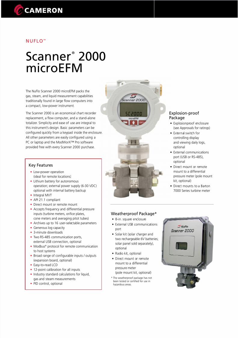
MEASUREMENT SYSTEMS NUFLO ™ Scanner ® 2000 microEFM The NuFlo Scanner 2000 microEFM packs the gas, steam, and liquid measurement capabilities traditionally found in large flow computers into a compact, low-power instrument. The Scanner 2000 is an economical chart recorder replacement, a flow computer, and a stand-alone totalizer . Simplicity and ease of use are integral to this instrument’ s design. Basic parameters can be configured quickly from a keypad inside the enclosure. All other parameters are easily configured using a PC or laptop and the ModWorX™ Pro software provided free with every Scanner 2000 purchase. Weatherproof Package* • 8-in. squar e en closur e • Extern al US B communications port • Solar kit (s olar ch arger and two rechargeable 6V batteries; solar panel sold separately), optional • Radio kit, optional • Direct mount or remote mount to a differential pressure meter (pole mount kit, optional) * The weatherproof package has not been tested or certified for use in hazardous areas. Explosion-proof Package • Explo sionpr oof e nclosu re (see Approvals for ratings) • External swit ch for controlling display and viewing daily logs, optional • External communicat ions port (USB or RS-485), optional • Dire ct mount or remote mount to a differential pressure meter (pole mount kit, optional) • Dire ct mounts to a Bar ton 7000 Series turbine meter Key Features • Low-power operation (ideal for remote locations) • Lithium battery for autonomous operation; external power supply (6-30 VDC) optional with internal battery backup • Integral MVT • API 21.1 compliant • Direct mount or remote mount • Accepts frequency and differential pressure inputs (turbine meters, orifice plates, cone meters and averaging pitot tubes) • Archives up to 16 user-sele ctable parameters • Generous log capacity • 3-minute downloads • T wo RS-485 communication ports, external USB connection, optional • Modbus ® protocol for remote communication to host systems • Broad range of configurable inputs / outputs (expansion board, optional) • Easy-to-read LCD • 12-point calibration for all inputs • Industry standard calculations for liquid, gas and steam measurements • PID control, optional
-
Upload
dennis-espinoza-rospigliosi -
Category
Documents
-
view
228 -
download
0
Transcript of Scanner 2000 Technical Data Sheet
7/27/2019 Scanner 2000 Technical Data Sheet
http://slidepdf.com/reader/full/scanner-2000-technical-data-sheet 1/4
M E A S U R E M E N T S Y S T E M
NUFLO™
Scanner
®
2000microEFM
The NuFlo Scanner 2000 microEFM packs the
gas, steam, and liquid measurement capabilities
traditionally found in large flow computers into
a compact, low-power instrument.
The Scanner 2000 is an economical chart recorder
replacement, a flow computer, and a stand-alonetotalizer. Simplicity and ease of use are integral to
this instrument’s design. Basic parameters can be
configured quickly from a keypad inside the enclosure.
All other parameters are easily configured using a
PC or laptop and the ModWorX™ Pro software
provided free with every Scanner 2000 purchase.
Weatherproof Package*• 8-in. square enclosure
• External USB communications
port
• Solar kit (solar charger and
two rechargeable 6V batteries;
solar panel sold separately),
optional
• Radio kit, optional
• Direct mount or remote
mount to a differential
pressure meter
(pole mount kit, optional)
* The weatherproof package has notbeen tested or certified for use inhazardous areas.
Explosion-proof
Package• Explosionproof enclosure
(see Approvals for ratings)
• External switch for
controlling display
and viewing daily logs,
optional
• External communications
port (USB or RS-485),
optional
• Direct mount or remote
mount to a differential
pressure meter (pole mountkit, optional)
• Direct mounts to a Barton
7000 Series turbine meter
Key Features
• Low-power operation
(ideal for remote locations)• Lithium battery for autonomous
operation; external power supply (6-30 VDC)
optional with internal battery backup
• Integral MVT
• API 21.1 compliant
• Direct mount or remote mount
• Accepts frequency and differential pressure
inputs (turbine meters, orifice plates,
cone meters and averaging pitot tubes)
• Archives up to 16 user-selectable parameters
• Generous log capacity
• 3-minute downloads
• Two RS-485 communication ports,external USB connection, optional
• Modbus® protocol for remote communication
to host systems
• Broad range of configurable inputs / outputs
(expansion board, optional)
• Easy-to-read LCD
• 12-point calibration for all inputs
• Industry standard calculations for liquid,
gas and steam measurements
• PID control, optional
7/27/2019 Scanner 2000 Technical Data Sheet
http://slidepdf.com/reader/full/scanner-2000-technical-data-sheet 2/42
ApprovalsExplosion-proof Package
• CE approved
• Complies with EMC Directive
2004/108/EC
• ATEX and IECEx certified,
II 2 GD Ex d IIC T6 IP68
(-40°C to 70°C)
• CSA certified for US and Canada
Class I, Div. 1, Groups B, C, D,
Type 4 enclosure, ANSI 12.27.01
single seal (0 to 3000 psi)
• Measurement Canada certifiedfor custody transfer, Approval
No. AG-0557C
• GOST-R/GOST-K certified
• ASME pressure vessel code
compliant (0 to 3000 psi);
CRN 0F10472.5C
Display• Two-line LCD with easy-to-read
alphanumeric characters
• 8-digit display of values (top line)
• 6-digit display identifies each
scrolling parameter and its
engineering unit (bottom line)
• View up to 12 user-defined
parameters
• View daily log data (99 days)
• User-selectable units of
measurement
• Character height - 0.3 in.
• Adjustable contrast and
update period
Calculations• Flow rate (natural gas, steam, liquid)
• AGA-3
• AGA-7
• Compensated Liquid Turbine
• ISO 5167
• Cone
• Averaging Pitot Tube (Annubar®)
• Fluid properties
• AGA-8-92 (Detail and Gross)
• IF-97 (Steam)
• Generic Liquid
(Water or Emulsions)
• API-2540 Liquid (Crude Oil, Jet
Fuel, Gasoline, Fuel Oils, Lube Oil)
• Wet correction (Steam)
• James (Orifice)
• Chisholm (Orifice)
• Steven (Cone)
Communications / Archive Retrieval• Modbus (RTU) with two on-board
RS-485 communications slave ports
• COM 1 and COM 2 baud rates:
300 to 38.4K• USB communications with
optional adapter
• Enron Modbus compliant downloads
• User-definable block reads allows the
grouping of up to 25 floating point
values for faster data transfer when
used with a SCADA system
• Full archive download in
approximately 3 minutes with
main board only (6 minutes with
expansion board option)
InputsTurbine Meter Inputs 1 and 2(Expansion Board Required for
Turbine Input 2)
• Configurable sensitivity adjustment
(20 mV to 200 mV, peak to peak)
• Frequency range: 0 to 3500 Hz
• Input amplitude: 20 mV to 3000 mV,
peak to peak
• Turbine Input 2 cannot be used
simultaneously with a pulse input
Pulse Input
(Expansion Board Required)• Accepts a signal from a turbine meter
or PD meter
• Optically isolated
• Input: 3 to 30 VDC or contact closure
• Cannot be used simultaneously
with Turbine Input 2
Analog Inputs 1 and 2
(Expansion Board Required)
• 3-wire sensor interface
• Sensor power same as external
power supply for main board
(6 to 30 VDC)• Accuracy: 0.1% of full scale
• Temperature effect: 0.25% of full
scale over operating temperature
range of -40°F to 158°F
(-40°C to 70°C)
• Resolution: 20 bits
• User-adjustable sample time
and damping
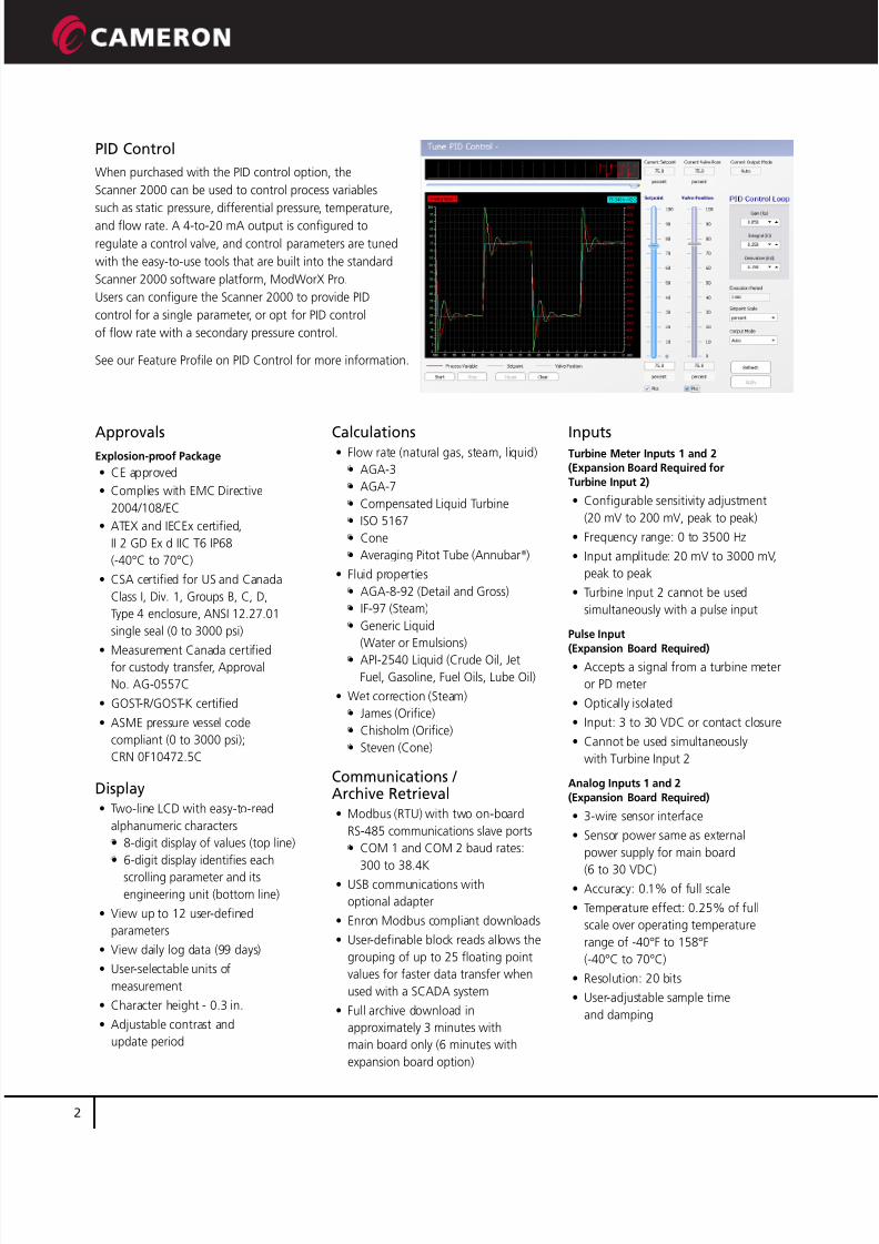
PID Control
When purchased with the PID control option, the
Scanner 2000 can be used to control process variables
such as static pressure, differential pressure, temperature,
and flow rate. A 4-to-20 mA output is configured to
regulate a control valve, and control parameters are tuned
with the easy-to-use tools that are built into the standard
Scanner 2000 software platform, ModWorX Pro.
Users can configure the Scanner 2000 to provide PID
control for a single parameter, or opt for PID control
of flow rate with a secondary pressure control.
See our Feature Profile on PID Control for more information.
7/27/2019 Scanner 2000 Technical Data Sheet
http://slidepdf.com/reader/full/scanner-2000-technical-data-sheet 3/4
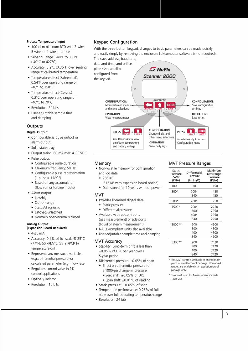
TEST ACCESS
CONFIGURATION:
Move between menusand menu selections
OPERATION:
View next parameter
OPERATION:
View daily logs
CONFIGURATION:
Change digits andother menu selections
CONFIGURATION:
Save configurationsettings
OPERATION:
Save totals
PRESS +
simultaneously to viewtime/date, temperature,and battery voltage
PRESS +
simultaneously to accessConfiguration menu
3
M E A S U R E M E N T S Y S T E M
Keypad Configuration
With the three-button keypad, changes to basic parameters can be made quickly
and easily simply by removing the enclosure lid (computer software is not required).
The slave address, baud rate,
date and time, and orifice
plate size can all be
configured from
the keypad.
Process Temperature Input
• 100-ohm platinum RTD with 2-wire,
3-wire, or 4-wire interface
• Sensing Range: -40°F to 800°F
(-40°C to 427°C)• Accuracy: 0.2°C (0.36°F) over sensing
range at calibrated temperature
• Temperature effect (Fahrenheit):
0.54°F over operating range of
-40°F to 158°F
• Temperature effect (Celsius):
0.3°C over operating range of
-40°C to 70°C
• Resolution: 24 bits
• User-adjustable sample time
and damping
Outputs
Digital Output
• Configurable as pulse output or
alarm output
• Solid-state relay
• Output rating: 60 mA max @ 30 VDC
• Pulse output
• Configurable pulse duration
• Maximum frequency: 50 Hz
• Configurable pulse representation
(1 pulse = 1 MCF)
• Based on any accumulator(flow run or turbine inputs)
• Alarm output
• Low/high
• Out-of-range
• Status/diagnostic
• Latched/unlatched
• Normally open/normally closed
Analog Output(Expansion Board Required)
• 4-20 mA
• Accuracy: 0.1% of full scale @ 25°C
(77°F), 50 PPM/°C (27.8 PPM/°F)
temperature drift
• Represents any measured variable
(e.g., differential pressure) or
calculated parameter (e.g., flow rate)
• Regulates control valve in PID
control applications
• Optically isolated
• Resolution: 16 bits
MVT Pressure Ranges
Static MaximumPressure Differential Overrange /SWP Pressure Pressure(PSIA) (In. H2O) (PSIA)
100 30 150
300* 200* 450
840 450
500* 200* 750
1500* 200* 2250
300 2250
400* 2250
840 2250
3000** 200 4500
300 4500
400 4500
840 4500
5300** 200 7420
300 7420400 7420
840 7420
* This MVT range is available in an explosion-proof or weatherproof package. Unmarkedranges are available in an explosion-proofpackage only.
** Not evaluated for Measurement Canada
approval
Memory• Non-volatile memory for configuration
and log data
• 256 KB
(512 KB with expansion board option)• Data stored for 10 years without power
MVT• Provides linearized digital data
• Static pressure
• Differential pressure
• Available with bottom ports
(gas measurement) or side ports
(liquid or steam measurement)
• NACE-compliant units also available
• User-adjustable sample time and damping
MVT Accuracy
• Stability: Long-term drift is less than±0.05% of URL per year over a
5-year period
• Differential pressure: ±0.05% of span
• Effect on differential pressure for
a 1000-psi change in pressure
• Zero shift: ±0.05% of URL
• Span shift: ±0.01% of reading
• Static pressure: ±0.05% of span
• Temperature performance: 0.25% of full
scale over full operating temperature range
• Resolution: 24 bits
7/27/2019 Scanner 2000 Technical Data Sheet
http://slidepdf.com/reader/full/scanner-2000-technical-data-sheet 4/4
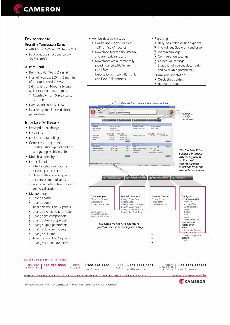
Four menus simplify navigation
Dedicated button for quick and easy downloads
Documentation for quick reference
Calibrate Inputs:
Differential PressureStatic PressureProcess Temperature
Configure:SYSTEM PARAMETERS
Device IDDate and TimeCommunicationsSecurityDisplayArchiveAlarmModbus Registers
FLOW RUN SETUP
TURBINE SETUP
INPUTSDifferential PressureStatic PressureProcess Temperature
OUTPUTS
Digital
Calibrate, Verify andSet Zero Offset selectiionsavailable for each parameter.
Maintain Flow Run:
Change Orifice PlateChange ConeChange Gas CompositionChange Steam PropertiesChange Flow CoefficientsChange Avg. Pitot Tube
Maintain Turbine:
Change TurbineFlowmeter
Change K-Factors
The ModWorX Pro software interfaceoffers easy accessto the most commonly used functions from one
main display screen.
Task-based menus help operators
perform their jobs quickly and easily.
+44.1243.826741
EUROPE,MIDDLE EAST
& AFRICA
M E A S U R E M E N T S Y S T E M S
U S A • C A N A D A • U K • C H I N A • U A E • A L G E R I A • M A L A Y S I A • I N D I A • R U S S I A www.c -a -m. c o m/ f lo
+603.5569.0501
ASIAPACIFIC
1.800.654.3760
NORTHAMERICA
281.582.9500HOUSTON
HEAD OFFICE
M E A S U R E M E N T S Y S T E M
EFM-2000 NF00097 1104 © Copyright 2011 Cameron International Corp. All Rights Reserved.
Environmental
Operating Temperature Range
• -40°F to +158°F (-40°C to +70°C)
• LCD contrast is reduced below
-22°F (-30°C)
Audit Trail• Daily records: 768 (>2 years)
• Interval records: 2304 (>3 months
of 1-hour intervals); 6392
(>8 months of 1-hour intervals)
with expansion board option
• Adjustable from 5 seconds to
12 hours
• Event/alarm records: 1152
• Records up to 16 user-defined
parameters
Interface Software• Provided at no charge
• Easy to use
• Real-time data polling
• Complete configuration
• Configuration upload tool for
configuring multiple units
• Multi-level security
• Field calibration
• 1 to 12 calibration points
for each parameter• Three methods: multi-point,
set zero point, and verify
• Inputs are automatically locked
during calibration
• Maintenance
• Change plate
• Change cone
(linearization: 1 to 12 points)
• Change averaging pitot tube
• Change gas composition
• Change steam properties
• Change liquid parameters
• Change flow coefficients
• Change K-factor
(linearization: 1 to 12 points)
• Change turbine flowmeter
• Archive data downloads
• Configurable downloads of
“all” or “new” records
• Download types: daily, interval,
and event/alarm records• Downloads are automatically
saved in uneditable binary
(SDF) files
• Exports to .xls, .csv, .rtf, .html,
and Flow-Cal® formats
• Reporting
• Daily logs (table or trend graph)
• Interval logs (table or trend graph)
• Event/alarm logs
• Configuration settings• Calibration settings
• Snapshot of current status data
and calculated parameters
• Online documentation
• Quick Start guides
• Hardware manual
• Software manual