Scaling OpenStack Clouds Using Peer-to-peer...
59
Department of Computer Science and Engineering CHALMERS UNIVERSITY OF TECHNOLOGY UNIVERSITY OF GOTHENBURG Gothenburg, Sweden 2016 Scaling OpenStack Clouds Using Peer-to-peer Technologies Master’s thesis in Computer Systems and Networks XIN HAN
Transcript of Scaling OpenStack Clouds Using Peer-to-peer...

Department of Computer Science and Engineering CHALMERS UNIVERSITY OF TECHNOLOGY UNIVERSITY OF GOTHENBURG Gothenburg, Sweden 2016
Scaling OpenStack Clouds Using Peer-to-peer Technologies Master’s thesis in Computer Systems and NetworksXIN HAN


Master’s thesis 2016:NN
Scaling OpenStack CloudsUsing Peer-to-peerTechnologies
XIN HAN
Department of Computer Science and EngineeringChalmers University of Technology And University of Gothenburg
Gothenburg, Sweden 2016

Scaling OpenStack CloudsUsing Peer-to-peer TechnologiesXIN HAN
© XIN HAN, 2016.
Supervisors:Vincenzo Gulisano, Department of Computer Science and EngineeringJoao Monteiro Soares, EricssonFetahi Wuhib, EricssonVinay Yadhav, Ericsson
Examiner:Magnus Almgren, Department of Computer Science and Engineering
Master’s Thesis 2016:NNDepartment of Computer Science and EngineeringChalmers University of Technology and University of GothenburgSE-412 96 GothenburgTelephone +46 31 772 1000
Cover: Illustration of P2P OpenStack cloud system. Each cloud is a standaloneOpenStack cloud instance. Cloud instances are federated as one using P2P tech-nologies.
Gothenburg, Sweden 2016
iv

Scaling OpenStack Clouds Using Peer-to-peerTechnologiesXIN HANDepartment of Computer Science and EngineeringChalmers University of Technology and University of Gothenburg
AbstractOpenStack is an open-source software platform for cloud computing, mostly de-ployed as an infrastructure-as-a-service (IaaS) and has a user base in industry andacademia to date. Despite its popularity, OpenStack still has drawbacks in terms ofscalability of number of compute nodes (metal machines) in a single cloud instance.More precisely, a single standard OpenStack cloud instance does not scale well andfails to handle user request once its number of compute nodes reaches a particularamount. The particular amount depends on how the cloud instance is deployed andhow many computing resources are provisioned to the cloud instance. This the-sis proposes a solution that allows to scale up OpenStack cloud instances by usingpeer-to-peer (P2P) technologies. The solution abstracts multiple OpenStack cloudinstances as one, providing the same user experience as using a single and standardOpenStack cloud instance. This thesis was done at Ericsson Research Departmentin Stockholm, Sweden. In the thesis, we design and develop a proof-of-concept ofthe solution by implementing a software agent which runs on an OpenStack cloudinstance, working as a message broker and providing OpenStack services to users.Association of agents is achieved by an inexpensive group membership protocol –Cyclon. We evaluate our P2P-based solution by comparing its system performancewith a standard OpenStack deployment in terms of response time, failure resistanceand CPU utilization. Results show that it is feasible to integrate virtual resourcesacross multiple OpenStack cloud instances while abstracting them as a single cloudinstance. Moreover, it is also shown that the proposed approach has higher failureresistance to certain operations (e.g. upload image and boot virtual machine). Inaddition, the solution has no limitation on a number of cloud instances and its per-formance, such as response time, failure resistance and CPU utilization, improveswith the increasing number of cloud instances.
Keywords: Cloud Computing, OpenStack, Peer-to-peer, Distributed Systems, Scal-ability.
v


Acknowledgements
I would like to show my sincere gratitude to my supervisor Vincenzo Gulisano andexaminer Magnus Almgren and Joao Monteiro Soares, Fetahi Wuhib, Vinay Yadhavat Ericsson for sharing their pearls of wisdom and assisting with my thesis workduring the whole process from proposing, planning, implementing to writing andDavid Bennehag and Yanuar T. Aditya Nugraha for their comments on an earlierversion of the manuscript.
Xin Han, Stockholm, December 2016
vii


Contents
List of Figures xi
List of Tables xiii
1 Introduction 11.1 Background . . . . . . . . . . . . . . . . . . . . . . . . . . . . . . . . 1
1.1.1 Peer-to-peer Overlay . . . . . . . . . . . . . . . . . . . . . . . 11.1.2 CYCLON Protocol . . . . . . . . . . . . . . . . . . . . . . . . 21.1.3 RESTful API . . . . . . . . . . . . . . . . . . . . . . . . . . . 21.1.4 OpenStack . . . . . . . . . . . . . . . . . . . . . . . . . . . . . 2
1.2 Problem Description . . . . . . . . . . . . . . . . . . . . . . . . . . . 31.3 Motivation . . . . . . . . . . . . . . . . . . . . . . . . . . . . . . . . . 5
2 Agent Design 72.1 Agent . . . . . . . . . . . . . . . . . . . . . . . . . . . . . . . . . . . 72.2 System Architecture . . . . . . . . . . . . . . . . . . . . . . . . . . . 72.3 Integration with OpenStack . . . . . . . . . . . . . . . . . . . . . . . 82.4 Resource Federation . . . . . . . . . . . . . . . . . . . . . . . . . . . 9
3 Agent Implementation 113.1 Agent Architecture . . . . . . . . . . . . . . . . . . . . . . . . . . . . 113.2 Agent DB . . . . . . . . . . . . . . . . . . . . . . . . . . . . . . . . . 123.3 Agent HTTP Server . . . . . . . . . . . . . . . . . . . . . . . . . . . 14
3.3.1 Agent API and Proxy Components . . . . . . . . . . . . . . . 143.4 Implementation of CYCLON protocol . . . . . . . . . . . . . . . . . . 193.5 Cloud Selection Scheduler . . . . . . . . . . . . . . . . . . . . . . . . 20
4 Evaluation and Result 234.1 Evaluation Framework . . . . . . . . . . . . . . . . . . . . . . . . . . 234.2 Experimental Environment Setup . . . . . . . . . . . . . . . . . . . . 23
4.2.1 Scenario One . . . . . . . . . . . . . . . . . . . . . . . . . . . 244.2.2 Scenario Two . . . . . . . . . . . . . . . . . . . . . . . . . . . 26
4.3 Experimental Results and Analysis . . . . . . . . . . . . . . . . . . . 264.3.1 Scenario One . . . . . . . . . . . . . . . . . . . . . . . . . . . 26
4.3.1.1 Response Time . . . . . . . . . . . . . . . . . . . . . 274.3.1.2 Failure Rate . . . . . . . . . . . . . . . . . . . . . . . 294.3.1.3 CPU Usage . . . . . . . . . . . . . . . . . . . . . . . 29
ix

Contents
4.3.1.4 Distribution of VMs . . . . . . . . . . . . . . . . . . 314.3.2 Scenario Two . . . . . . . . . . . . . . . . . . . . . . . . . . . 32
4.3.2.1 Response Time . . . . . . . . . . . . . . . . . . . . . 324.3.2.2 CPU Usage . . . . . . . . . . . . . . . . . . . . . . . 32
5 Future Work 35
6 Related Work 37
7 Discussion and Conclusion 417.1 Societal and ecological contribution . . . . . . . . . . . . . . . . . . . 417.2 Conclusion . . . . . . . . . . . . . . . . . . . . . . . . . . . . . . . . . 41
Bibliography 43
x
List of Figures
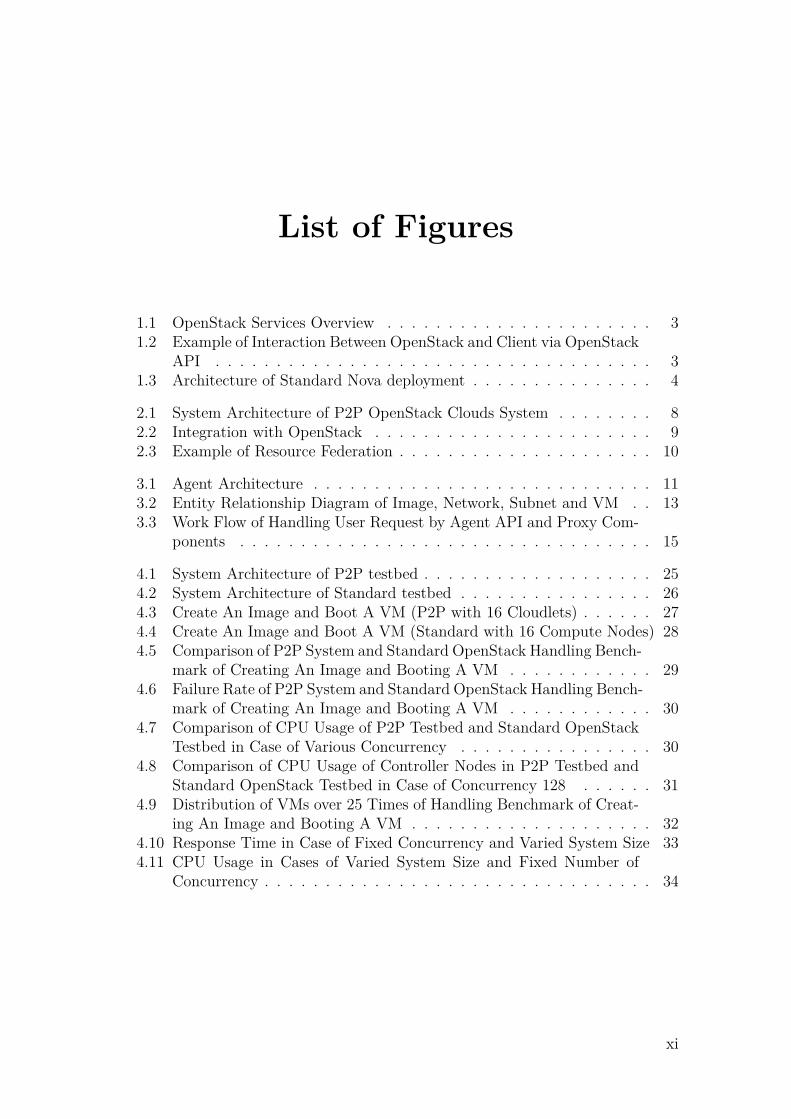
1.1 OpenStack Services Overview . . . . . . . . . . . . . . . . . . . . . . 31.2 Example of Interaction Between OpenStack and Client via OpenStack
API . . . . . . . . . . . . . . . . . . . . . . . . . . . . . . . . . . . . 31.3 Architecture of Standard Nova deployment . . . . . . . . . . . . . . . 4
2.1 System Architecture of P2P OpenStack Clouds System . . . . . . . . 82.2 Integration with OpenStack . . . . . . . . . . . . . . . . . . . . . . . 92.3 Example of Resource Federation . . . . . . . . . . . . . . . . . . . . . 10
3.1 Agent Architecture . . . . . . . . . . . . . . . . . . . . . . . . . . . . 113.2 Entity Relationship Diagram of Image, Network, Subnet and VM . . 133.3 Work Flow of Handling User Request by Agent API and Proxy Com-
ponents . . . . . . . . . . . . . . . . . . . . . . . . . . . . . . . . . . 15
4.1 System Architecture of P2P testbed . . . . . . . . . . . . . . . . . . . 254.2 System Architecture of Standard testbed . . . . . . . . . . . . . . . . 264.3 Create An Image and Boot A VM (P2P with 16 Cloudlets) . . . . . . 274.4 Create An Image and Boot A VM (Standard with 16 Compute Nodes) 284.5 Comparison of P2P System and Standard OpenStack Handling Bench-
mark of Creating An Image and Booting A VM . . . . . . . . . . . . 294.6 Failure Rate of P2P System and Standard OpenStack Handling Bench-
mark of Creating An Image and Booting A VM . . . . . . . . . . . . 304.7 Comparison of CPU Usage of P2P Testbed and Standard OpenStack
Testbed in Case of Various Concurrency . . . . . . . . . . . . . . . . 304.8 Comparison of CPU Usage of Controller Nodes in P2P Testbed and
Standard OpenStack Testbed in Case of Concurrency 128 . . . . . . 314.9 Distribution of VMs over 25 Times of Handling Benchmark of Creat-
ing An Image and Booting A VM . . . . . . . . . . . . . . . . . . . . 324.10 Response Time in Case of Fixed Concurrency and Varied System Size 334.11 CPU Usage in Cases of Varied System Size and Fixed Number of
Concurrency . . . . . . . . . . . . . . . . . . . . . . . . . . . . . . . . 34
xi

List of Figures
xii

List of Tables
3.1 Mapping Between CRD And HTTP Methods . . . . . . . . . . . . . 153.2 Mapping Agent Service APIs and Identity Service APIs . . . . . . . . 163.3 Mapping Between Agent Service APIs and Image APIs . . . . . . . . 163.4 Mapping Between Agent Service APIs and Networking APIs . . . . . 163.5 Mapping Between Agent Service APIs and Compute APIs . . . . . . 17
4.1 Four Types of Node Configuration . . . . . . . . . . . . . . . . . . . . 244.2 Services Run on Keystone Node, Controller Node and Compute Node
of P2P System . . . . . . . . . . . . . . . . . . . . . . . . . . . . . . 244.3 Create An Image and Boot A VM (P2P System with 16 Cloudlets) . 274.4 Create An Image and Boot A VM (Standard OpenStack with 16
Compute Nodes) . . . . . . . . . . . . . . . . . . . . . . . . . . . . . 284.5 Create An Image and Boot A VM (P2P System with Varied System
Size in Case of Concurrency 16) . . . . . . . . . . . . . . . . . . . . . 33
xiii

List of Tables
xiv

1Introduction
1.1 Background
Cloud computing is an Internet-based computing which provides shared and on-demand computer processing resources in terms of networks, servers, storage andservices. It enables enterprises and users to store and process their data with elasticcapabilities. A cloud is a large-scale distributed system that dynamically providescomputing resources as a service. The services provided by cloud are generallyclassified into di�erent models such as Infrastructure-as-a-Service(IaaS), Platform-as-a-Service(PaaS) and Software-as-a-Service(SaaS) [1].
1.1.1 Peer-to-peer Overlay
Due to the growth of Internet in terms of size and speed in the past few years,deployment of networks and services indicate a shift from traditional server-clientmodels to fully distributed Peer-to-peer(P2P) models. In P2P system, peers collab-orate with each other, sharing duties and benefits. Peers are capable of operatinglarge-scale tasks in a simple and scalable way by distributing responsibilities amongparticipating peers, instead of depending on dedicated, expensive, and hard to man-age centralized servers.
Presently, there are three main categories of P2P systems in terms of overlay man-agement. One is structured P2P system which imposes a linkage structure amongpeers such as Distributed Hash Table [2]. Notable distributed overlays which useDHTs include the Kad network, the Coral Content Distribution Network, YaCy, theStorm botnet, and BitTorrent’s distributed tracker [3]. Another one is unstructuredP2P system, peers are created either based on proximity metric probabilistically orjust randomly, instead of being imposed to be a particular structure on the overlaynetwork by design. Gnutella, Gossip, and Kazaa are examples of unstructured P2Pprotocols [4]. The third category is the hybrid model which is a combination ofserver-client and P2P models to have a central server that helps peers find eachother. Currently, the hybrid model is possession of better performance than eitherpure structured overlays or pure unstructured overlays as certain functions, suchas searching, requires a centralized functionality but benefit from the decentralizedaggregation of nodes provided by unstructured networks [5].
1

1. Introduction
1.1.2 CYCLON ProtocolCYCLON is a gossip-based, highly scalable, robust, completely decentralized andinexpensive group management protocol for unstructured overlays. CYCLON pro-tocol is shown to construct graphs that have low diameter, low clustering, highlysymmetric node degrees, and that are highly resilient to massive node failures. More-over, it is highly reactive to restoring randomness when a large number of nodes fail.CYCLON protocol does not maintain any global information or require any sort ofadministration, instead, each peer knows a small, continuously changing set of otherpeers, named its neighbors and periodically contacts a neighbor with the highestage from to exchange part of their neighbors.
1.1.3 RESTful APIRepresentational state transfer (RESTful) web services provide interoperability be-tween computing systems on the Internet. It is a software architectural designpattern and a practical approach for web application development where a systemneeds to scale out or needs a simple way to interact with independent components[6]. An Application Programming Interface (API) that follows the RESTful fash-ion is called a RESTful API. RESTful API uses Uniform Resource Identifier (URI)to represent resources, it is scalable and stateless. The original HTTP verbs mapto operations on resources. GET method is used for getting the resources; POSTmethod is used for creating a new resource; PUT method is used for updating aresource by resource’s id and DELETE method is used for deleting a resource or acollection of resources.
1.1.4 OpenStackOpenStack is an open source IaaS cloud computing platform widely used in industry[7]. It consists of interrelated components that control hardware pools of computing,storage and networking resources throughout a data center and empowers usersto provision resources. Notable users of OpenStack are NASA, PayPal and eBay.OpenStack embraces a modular architecture and comprises a set of interrelatedservices. Below is a quick breakdown of what they are called in OpenStack, andwhat they do.
• Compute service(Nova): Nova is a component which allows users to create andmanage virtual machines (VMs) using machine images. It is the brain of acloud. Nova facilitates management of VMs through an abstraction layer thatinterfaces with supported hypervisors.
• Identity service (Keystone): Keystone provides a central directory of usersmapped to the OpenStack services. It is used to provide an authenticationand authorization service for other OpenStack services throughout the entirecloud infrastructure.
• Image service (Glance): Glance provides image discovery, registration anddelivery services to Nova, as needed.
• Networking (Neutron): A component for managing virtual networks. Neutronprovides various networking services to cloud users (tenants) such as IP ad-
2
1. Introduction
dress management, DNS, DHCP, load balancing, and security groups (networkaccess rules, like firewall policies).
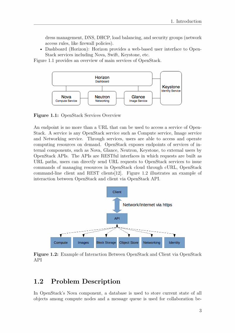
• Dashboard (Horizon): Horizon provides a web-based user interface to Open-Stack services including Nova, Swift, Keystone, etc.
Figure 1.1 provides an overview of main services of OpenStack.
Figure 1.1: OpenStack Services Overview
An endpoint is no more than a URL that can be used to access a service of Open-Stack. A service is any OpenStack service such as Compute service, Image serviceand Networking service. Through services, users are able to access and operatecomputing resources on demand. OpenStack exposes endpoints of services of in-ternal components, such as Nova, Glance, Neutron, Keystone, to external users byOpenStack APIs. The APIs are RESTful interfaces in which requests are built asURL paths, users can directly send URL requests to OpenStack services to issuecommands of managing resources in OpenStack cloud through cURL, OpenStackcommand-line client and REST clients[12]. Figure 1.2 illustrates an example ofinteraction between OpenStack and client via OpenStack API.
Figure 1.2: Example of Interaction Between OpenStack and Client via OpenStackAPI
1.2 Problem DescriptionIn OpenStack’s Nova component, a database is used to store current state of allobjects among compute nodes and a message queue is used for collaboration be-
3

1. Introduction
tween services in Nova such as nova-api, nova-conductor, nova-scheduler and nova-compute. Figure 1.3 shows the architecture of a standard Nova deployment. Novaservices can be deployed on di�erent physical machines. The message queue can beeither RabbitMQ or Qpid and it is a central messaging component which enablescommunication and interoperability between Nova components in a loosely couplefashion.
Figure 1.3: Architecture of Standard Nova deployment
Despite OpenStack’s popularity, Nova still has limited scalability in terms of scalingup amount of compute nodes. More precisely, the database and the message queueof OpenStack Nova are identified as bottlenecks [8, 9]. In a test case of Cisco’stesting report [9], the test was monitored using RabbitMQ management plugin andwas done by adding compute nodes to OpenStack cloud simultaneously. The findingof this test case was that number of RabbitMQ Socket Descriptors was the limitingfactor at 147 compute nodes per cloud controller. From Cisco’s testing result, weknow that OpenStack does not scale well when a quantity of compute nodes reachesa specific number.
As an open source project, OpenStack has been significantly developed for years,however, the scalability drawback has not been perfectly solved yet. For the sakeof solving the scalability issue, one can look at this problem from di�erent angles.One way to look at this problem is component wise. A solution could be fixingthe problem of each individual component, for instance, message queue of Novacomponent. However, due to OpenStack’s complexity, solving scalability problemin this way would be extremely complicated and would take a risk of a�ectingintegrity with other components. Besides, in order to scale an OpenStack cloudinstance (cloudlet) in terms of compute nodes, even if the message queue issue ofNova is solved, all other components, such as Neutron and Glance, still need to bescalable to satisfy service demand of increased number of compute nodes as well.From another angle to look at this problem, instead of aiming to solve scalabilityissue of an individual component, we can solve the scalability issue on a higher
4

1. Introduction
and abstracted level by associating multiple clouds instances as one cloud cluster,regardless of the scalability properties of each cloud instance or individual OpenStackcomponent. A possible solution could be scaling OpenStack cloud instances usingP2P technologies and providing an abstraction of these collaborated cloud instancesas one in order to enable the abstracted system to allocate as many compute nodesas all associated cloud instances could do so.
1.3 MotivationThis thesis aims to provide a solution for scaling OpenStack cloud instances on cloudcluster level. Scaling standalone OpenStack cloud instances using P2P technologiesand abstracting these cloud instances as one without a�ecting end-user experienceare what we aim to solve in this thesis. In order to associate multiple OpenStackcloud instances, an additional software agent is supposed to be implemented anddeployed on each cloud instance, working as a message broker and providing servicesof its a�liated OpenStack cloud to end users. Agents on di�erent cloud instancesshould be interconnected to each other to comprise a P2P network. By abstractingOpenStack cloud instances through agents, physical resources such as computingcapacity, storage and network are capable of being shared across distinct cloudinstances. By scaling cloud instances using P2P technologies, an OpenStack cloudinstance is supposed to easily join or leave the P2P system without causing anyimproper functioning and the whole system should be scalable and flexible.
This thesis report is structured as follows. Chapter 2 provides an overview of agentdesign. Chapter 3 discusses the implementation of agent in details. Chapter 4evaluates the proposed solution and shows evaluation results, whereas chapter 5and chapter 6 provide a discussion of future work and related work, separately.Finally, chapter 7 concludes this thesis.
5

1. Introduction
6

2Agent Design
The chapter presents what the agent is for, the system architecture of our proposedP2P system with agents plugged on each OpenStack cloud instance, how does thepluggable agent integrate with OpenStack cloud instance and group membershipamong cloud instances.
2.1 AgentAn agent is a message broker which is supposed to be implemented and pluggedon each OpenStack cloud instance. Agent acts as proxy between OpenStack cloudinstances and end users which enables resource federation and collaboration amongcloud instances. In standard OpenStack deployment, a single user request is notfeasible to forwarded across multiple cloud instances and virtual resources that auser acquires on distinct cloud instances lacks relevant association. While in ourproposed P2P system, each agent runs on its a�liated OpenStack cloud instanceand provides its own dedicated RESTful service endpoints to serve end users. Moreprecisely, agent maps received user request to a standard OpenStack user request andforwards the request to corresponding cloud instance’s RESTful service endpoint.Besides, agent federates computing resources from cloud instances and is capable ofprovisioning or allocating resources on-demand and it maintains associated relationamong resources that user acquires on distinct cloud instances. In addition, eachagent keeps possession of a list of cloud instances based on the CYCLON groupmembership protocol that we will discuss in the following section. These cloudinstances on the list are called neighbors and the list is called neighbor list. Froman user’s view, an agent is an entry point of the abstracted P2P system and cloudinstances behind the agent are transparent. Instead of sending request to originalOpenStack service endpoints, user sends requests to agent’s service endpoints by thesame manner of using a standard OpenStack cloud instance. With agents, multiplecloud instances act as one.
2.2 System ArchitectureIn OpenStack, a region is a logical fence used to group OpenStack services in closeproximity to one another [10]. In other words, an OpenStack cloud instance is anindependent region. With OpenStack multi-region deployment, the identity serviceKeystone, which is used by all other OpenStack components for authentication andauthorization, is capable of serving multiple OpenStack cloud instances.
7
2. Agent Design
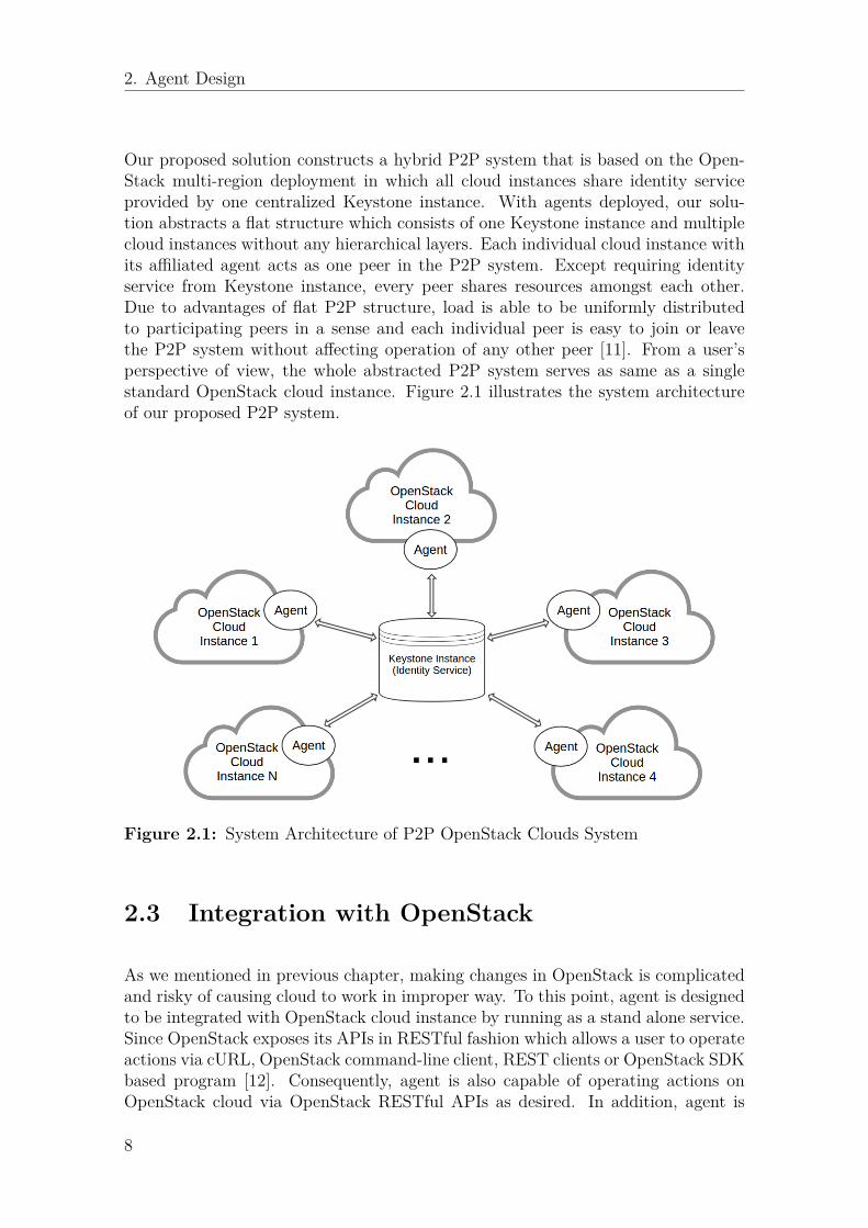
Our proposed solution constructs a hybrid P2P system that is based on the Open-Stack multi-region deployment in which all cloud instances share identity serviceprovided by one centralized Keystone instance. With agents deployed, our solu-tion abstracts a flat structure which consists of one Keystone instance and multiplecloud instances without any hierarchical layers. Each individual cloud instance withits a�liated agent acts as one peer in the P2P system. Except requiring identityservice from Keystone instance, every peer shares resources amongst each other.Due to advantages of flat P2P structure, load is able to be uniformly distributedto participating peers in a sense and each individual peer is easy to join or leavethe P2P system without a�ecting operation of any other peer [11]. From a user’sperspective of view, the whole abstracted P2P system serves as same as a singlestandard OpenStack cloud instance. Figure 2.1 illustrates the system architectureof our proposed P2P system.
Figure 2.1: System Architecture of P2P OpenStack Clouds System
2.3 Integration with OpenStack
As we mentioned in previous chapter, making changes in OpenStack is complicatedand risky of causing cloud to work in improper way. To this point, agent is designedto be integrated with OpenStack cloud instance by running as a stand alone service.Since OpenStack exposes its APIs in RESTful fashion which allows a user to operateactions via cURL, OpenStack command-line client, REST clients or OpenStack SDKbased program [12]. Consequently, agent is also capable of operating actions onOpenStack cloud via OpenStack RESTful APIs as desired. In addition, agent is
8

2. Agent Design
designed to provide RESTful HTTP service to work as a message broker which sitesbetween its a�liated OpenStack cloud instance and users, and performs mapping ofagent service endpoints and cloud service endpoints. More precisely, agent listenson a specific port and waits for requests from users. Figure 2.2 illustrates how agentworks as message broker between cloud instances and users. As shown in this figure,user interacts with agent via RESTful request and agent acquires services from cloudinstances via RESTful request as well. By given an example, a user sends a requestto the service endpoint of agent, once the request is received by the agent, the agentfirstly do a mapping between its service endpoint and service endpoint of OpenStackcloud instance, then it forwards the request to the corresponding cloud instance’sservice endpoint via OpenStack’s RESTful API.
Figure 2.2: Integration with OpenStack
2.4 Resource FederationCloud based services are a growing business trend in the IT industry, where serviceproviders establish cloud and o�er computing resources (infrastructure, platformand software) to consumers. Consumers often require virtual resources across mul-tiple cloud instances, to settle their application needs. Single cloud provider may notbe able to address such requests because of lack of capacity or presence in multiplecloud instances. Enterprises are adopting cloud based service to address their grow-ing computing workload and they need resources across multiple cloud instances.These instances sometimes span across multiple geographical locations. In this the-sis work, the desired solution is to provide users an abstraction of OpenStack cloudinstances as one based on P2P overlay without a�ecting user experience. In orderto achieve this goal and e�ciently utilise virtual resources of various OpenStackcloud instances, such as CPU, RAM, network, image file and storage, resources ofthese cloud instances are supposed to be federated and provided altogether to users.Resource federation is recognized as a promising mechanism aimed at the intercon-nection of heterogeneous resources across several independent cloud infrastructures.In order to provide a larger-scale and higher performance infrastructure, federationenables on-demand provisioning of complex service and user can get access to muchlarger pools of resources. However, OpenStack virtual resources are not feasible tobe shared across distinct clouds. For instance, an image file of cloud A can notbe used in cloud B when boots a VM in cloud B. In order to solve this problem,the agent is designed to be capable of managing resources across distinct cloud in-stances. Resource provisioning is required to e�ciently allocate limited resource on
9

2. Agent Design
resource provider cloud. Also, Provisioning is needed to provide sense of ownershipto end user. Agent is responsible for provisioning remote resources. It also maintainsprovisioning information in a local database. The provisioning info will be used forthe purpose of resource info query. Figure 2.3 shows an example of resource feder-ation, a user owns virtual resources from remote clouds on a local project throughan agent. One benefit of resource federation is that a user can use a single projectin host cloud to scope all the remote virtual resources across cloud instances.
Figure 2.3: Example of Resource Federation
10

3Agent Implementation
This chapter discusses implementation details of the agent, including agent archi-tecture, agent database, agent HTTP server, agent proxies and scope of OpenStackAPIs that the agent supports. The software agent is purely developed in Pythonand mainly uses modules come with OpenStack installation.
3.1 Agent ArchitectureThe agent consists of multiple components, an Agent DB, an HTTP server, fourproxies, a CYCLON component in which a process of CYCLON protocol runs peri-odically and a Scheduler component. The HTTP server provides service for AgentAPI, Keystone Proxy, Glance Proxy, Neutron Proxy and Nova Proxy. Figure 3.1shows agent architecture and responsibilities of each component are listed below.
Figure 3.1: Agent Architecture
• Agent DB: Runs MySQL database service and is responsible for storing user’sresource allocation information.
• HTTP Server: Listens on a specific port, forwards request from a user toOpenStack cloud and deliver response from OpenStack cloud to the user.
• Agent API: Exposes agent’s service endpoint to user by providing RESTfulAPIs.
• Keystone Proxy: Works as proxy and maps agent’s service endpoint to Open-Stack Identity service endpoint.
• Glance Proxy: Works as a broker and maps agent’s service endpoint to Open-Stack Image service endpoint.
11

3. Agent Implementation
• Neutron Proxy: Works as broker and maps agent’s service endpoint to Open-Stack Networking service endpoint.
• Nova Proxy: Works as broker and maps agent’s service endpoint to OpenStackcompute service endpoint.
• CYCLON: An implementation of Cyclon protocol. Maintains a list of itsa�liated agent’s neighbors and exchanges its view of neighbors with otheragents periodically.
• Cloud Selection Scheduler: Comprised of filters and weighers. When receivesa virtual resource creation request, selects an OpenStack cloud instance tocreate requested virtual resource based on strategies of filters and weighers.
Every agent component collaborates with each other to serve users. Once user re-quest arrives at agent HTTP server, Agent API component distributes the requestto Keystone proxy, Glance proxy, Neutron proxy or Nova proxy relevantly, waitingfor the response from the related proxy. These four proxies are brokers betweenagent and OpenStack clouds, they receive mapped user request from Agent APIcomponent and forwards the request to relevant OpenStack cloud according to in-formation stored in Agent DB in the case of querying or deleting a virtual resource,or decision made by cloud selection scheduler in the case of creating virtual resource[14]. Once receives a request of creating or deleting a virtual resource, the Agent DBis updated after the relevant request is successfully operated by OpenStack cloud.The CYCLON component runs Cyclon protocol, periodically swaps neighbor listwith another agents in P2P system and provides neighbors’ information to its a�li-ated agent when choosing an OpenStack cloud instance to create a virtual resource.Details of agent components will be discussed in following sections.
3.2 Agent DBThe Agent DB components provides persistent data storing service. Instead ofdirectly using OpenStack database, in this solution, a dedicated database is used bythe agent to insert, delete and read data of users’ virtual resource information. Asa proof-of-concept, this solution only considers entities such as project, user, image,network, subnet and VM. A project has multiple users and a user can belong tomultiple projects with various authorities; A project can have several networks anda network can be shared with several projects; A network contains multiple subnetsand a subnet can be shared with multiple VMs; A project has multiple VMs andan image boots several VMs. Except for VM, each entity such as image, network,subnet has a unique id originally created by its a�liated OpenStack cloud instance,called uuid_cloud in this solution, and a unique id created by its a�liated agent,called uuid_agent in this solution. The uuid_cloud is only unique within entity’sa�liated OpenStack cloud, while the uuid_agent is globally unique within the wholeP2P system. Since an entity excepts VM can be located at multiple OpenStackcloud instances, so the relationship between uuid_agent and the uuid_cloud is one-to-many. In other words, one uuid_agent can be mapped to multiple uuid_cloud.Instead of sending a request with entity’s original unique id created by OpenStackcloud instance when deleting or querying information of network, subnet or image,
12

3. Agent Implementation
user sends a request with the globally unique id created by the agent. As each VM isglobally unique and a VM is infeasible to be at multiple clouds, so it’s not necessaryto generate uuid_agent for VM. The unique id of a VM stored in agent databaseis just the unique id originally created by its a�liated OpenStack cloud instance.Figure 3.2 show an Entity-Relationship diagram (ER-diagram) of image, network,subnet and VM.
Figure 3.2: Entity Relationship Diagram of Image, Network, Subnet and VM
The Agent DB stores data for entities such as image, network, subnet and VM, andit is updated only in case of creating or deleting a virtual resource successfully. AsMySQL comes with OpenStack installation, so in this solution MySQL is used as thededicated database in Agent DB. The agent database contains four tables which areImage table, Network table, Subnet table and VM table. A Python SQL toolkit andObject Relational Mapper (ORM) – SQLAlchemy is used to interact with MySQL.SQLAlchemy provides e�cient database access and it is able to classifies data setinto object models in a decoupled way [15]. As a virtual resource is possible inmultiple clouds, uuid_cloud holds the property of primary key.
Agent DB works as a supporting component to store user’s virtual resource allo-cation information for this P2P solution. When the agent receives a request ofquerying virtual resource information, it first looks up through its Agent DB andmaps uuid_agent to uuid_cloud, then forwards request to relevant OpenStack cloud
13

3. Agent Implementation
instance’s service endpoint by using the mapped uuid_cloud. The case of receivinga request of deleting resource is similar to receiving a request of querying, the onlydi�erence is if the virtual resource is successfully deleted by OpenStack cloud, theagent updates its local database by removing the entry for the deleted resource. Inthe case of receiving a request of creating a virtual resource, agent forwards therequest to service endpoint of chosen OpenStack cloud instance, if the request issuccessfully operated by cloud instance, then agent generates a globally unique idfor the created virtual resource and update its local agent database by inserting anew entry to the relevant data table.
3.3 Agent HTTP Server
Agent HTTP server is based on Python Web Server Gateway Interface (WSGI).WSGI is capable of serving as interface between web applications and servers [16].Conceptually, WSGI interface consists of "server" side and "application" side, wherethe "application" side is invokable by the "server" side. In our solution, the agentHTTP server is implemented using a Python library – Eventlet. Eventlet is a con-current networking library for Python that provides built-in WSGI interface [17]and uses libevent, an event notification library, for highly scalable non-blocking I/O[18]. Apart from this two strengths, Evenlet is developed based on green threadswhich are capable of doing networking tasks and work in cooperative fashion [19].The agent HTTP server initiates a pool of green threads which pools control con-currency at boot time. This is beneficial to limit amount of memory an applicationcan consume or make application behave consistently in the case of handling unpre-dictable incoming connection. By default, the size of the green pool is 1000. Everytime, the agent HTTP server receives a RESTful request from a user, it firstly parsesthis request based on requested API URL then invoke "application" side which isthe relevant callable proxy component, meanwhile, the user remains waiting untilgets any response. Once the relative operation is done by proxy component, theagent HTTP server sends a response back to the user and terminates the connec-tion between user and agent HTTP server. In addition, a waiting time is definedat the server side, instead of making a user wait for unnecessary long time, if therelevant proxy component does not respond after a timeout, the agent HTTP serverraises an exception and sends an error message back to the user and terminate theconnection.
3.3.1 Agent API and Proxy ComponentsAgent sits between its a�liated cloud and users, acting as a message broker, re-ceiving RESTful requests from users, mapping Agent APIs to OpenStack APIs andforwarding mapped request to OpenStack service endpoints. Agent exposes its inter-nal services by providing RESTful APIs in the same manner as OpenStack RESTfulAPIs. The only di�erence is that various OpenStack service endpoints listen ontheir dedicated ports, instead, agent service endpoints listen on one specific port.An Agent API scheme is shown below:
14

3. Agent Implementation
http://<agent-ip>:<agent-port>/<su�x>
Agent parses received request based on HTTP method and URL su�x, then forwardsthe parsed request to the relevant proxy component. The mapping between agentservice endpoint and OpenStack service endpoint is operated by the relevant proxycomponent such as Keystone Proxy, Glance Proxy, Neutron Proxy and Nova Proxy.Each proxy component maps parsed request from Agent API to OpenStack serviceendpoint and forwards mapped request to OpenStack service endpoint, waiting forthe response from OpenStack. Figure 3.3 illustrates the work flow of handling userrequest by Agent API and relevant proxy components.
Figure 3.3: Work Flow of Handling User Request by Agent API and Proxy Com-ponents
As a proof of concept, agent supports partial major OpenStack APIs which supportsCreate, Read, Delete (CRD) operations of OpenStack Identity API, Compute API,Image service API and Networking API. Each letter in the acronym CRD can mapto an HTTP method. Table 3.1 shows the mapping between CRD operations andHTTP methods.
Table 3.1: Mapping Between CRD And HTTP Methods
Operation MethodCreate PUT/POSTRead GETDelete DELETE
Agent API is strictly based on RESTful API, and exposes agent’s service endpointsto users. From a user’s perspective, the user just needs to send a request to AgentAPI endpoint, instead of sending a request to standard OpenStack API endpoint.As Agent API is in an OpenStack fashion, in which user has the same experienceofV using standard OpenStack.
OpenStack Identity service generates authentication tokens that permit access toOpenStack services’ REST APIs. Users obtain this token and the URL endpoints
15

3. Agent Implementation
for other service APIs by supplying their valid credentials to the authentication ser-vice. Table 3.2 shows APIs mapping between OpenStack Agent service and Identityservice.
Table 3.2: Mapping Agent Service APIs and Identity Service APIs
Method Agent Service Endpoint Identity Service Public Endpoint UsagePOST :port/v3/auth/tokens :5000/v3/auth/tokens Authenticate identity and generates to-
kenGET :port/v3/auth/tokens :5000/v3/auth/tokens Validate and show information for to-
ken
OpenStack Image service is responsible for storing virtual machine images and main-taining a catalog of available images. Table 3.3 shows the mapping between Open-Stack Image service APIs and Agent APIs.
Table 3.3: Mapping Between Agent Service APIs and Image APIs
Method Agent Service Endpoint Image Service Public Endpoint UsageGET :port/v2/images :9292/v2/images List public virtual ma-
chine (VM) imagesPOST :port/v2/images :9292/v2/images Creates a virtual machine
(VM) imageGET :port/v2/images/{image_id} :9292/v2/images/{image_id} Show details for an imageDELETE :port/v2/images/{image_id} :9292/v2/images/{image_id} Delete an imagePUT :port/v2/images/{image_id}/file :9292/v2/images/{image_id}/file Upload binary image dataGET :port/v2/images/{image_id}/file :9292/v2/images/{image_id}/file Download binary image
data
OpenStack Networking API is used for managing virtualized networking resourcesuch as networks, subnets and ports. The APIs mapping between Agent service andOpenStack Networking is shown in Table 3.4.
Table 3.4: Mapping Between Agent Service APIs and Networking APIs
Method Agent Service Endpoint Networking Public Endpoint UsageGET :port/v2.0/networks :9696/v2.0/networks List networksPOST :port/v2.0/networks :9696/v2.0/networks Create a networkGET :port/v2.0/networks/{network_id} :9696/v2.0/networks/{network_id} Show network detailsDELETE :port/v2.0/networks/{network_id} :9696/v2.0/networks/{network_id} Delete networkGET :port/v2.0/subnets :9696/v2.0/subnets List subnetsPOST :port/v2.0/subnets :9696/v2.0/subnets Create subnetsGET :port/v2.0/subnets/{subnet_id} :9696/v2.0/subnets/{subnet_id} Show subnet detailsDELETE :port/v2.0/subnets/{subnet_id} :9696/v2.0/subnets/{subnet_id} Delete subnetGET :port/v2.0/ports :9696/v2.0/ports List portsPOST :port/v2.0/ports :9696/v2.0/ports Create portsGET :port/v2.0/ports/{port_id} :9696/v2.0/ports/{port_id} Show port detailsDELETE :port/v2.0/ports/{port_id} :9696/v2.0/ports/{port_id} Delete port
OpenStack Compute API is an interface of Compute service that provides server
16
3. Agent Implementation
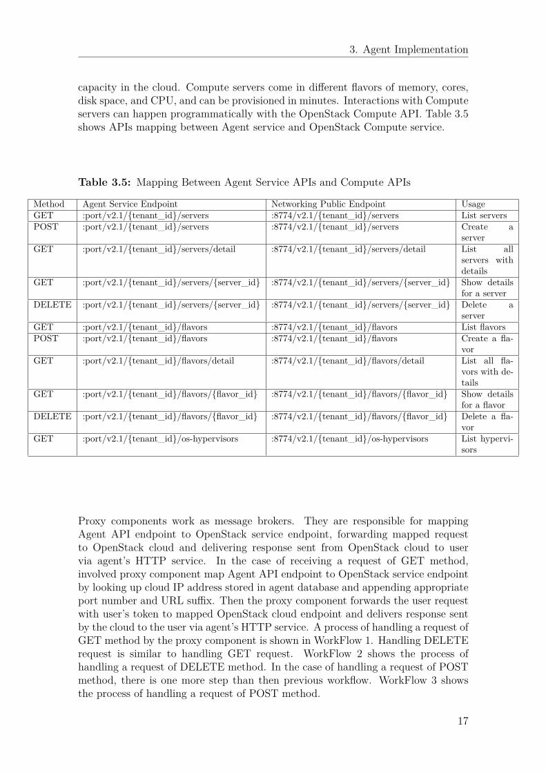
capacity in the cloud. Compute servers come in di�erent flavors of memory, cores,disk space, and CPU, and can be provisioned in minutes. Interactions with Computeservers can happen programmatically with the OpenStack Compute API. Table 3.5shows APIs mapping between Agent service and OpenStack Compute service.
Table 3.5: Mapping Between Agent Service APIs and Compute APIs
Method Agent Service Endpoint Networking Public Endpoint UsageGET :port/v2.1/{tenant_id}/servers :8774/v2.1/{tenant_id}/servers List serversPOST :port/v2.1/{tenant_id}/servers :8774/v2.1/{tenant_id}/servers Create a
serverGET :port/v2.1/{tenant_id}/servers/detail :8774/v2.1/{tenant_id}/servers/detail List all
servers withdetails
GET :port/v2.1/{tenant_id}/servers/{server_id} :8774/v2.1/{tenant_id}/servers/{server_id} Show detailsfor a server
DELETE :port/v2.1/{tenant_id}/servers/{server_id} :8774/v2.1/{tenant_id}/servers/{server_id} Delete aserver
GET :port/v2.1/{tenant_id}/flavors :8774/v2.1/{tenant_id}/flavors List flavorsPOST :port/v2.1/{tenant_id}/flavors :8774/v2.1/{tenant_id}/flavors Create a fla-
vorGET :port/v2.1/{tenant_id}/flavors/detail :8774/v2.1/{tenant_id}/flavors/detail List all fla-
vors with de-tails
GET :port/v2.1/{tenant_id}/flavors/{flavor_id} :8774/v2.1/{tenant_id}/flavors/{flavor_id} Show detailsfor a flavor
DELETE :port/v2.1/{tenant_id}/flavors/{flavor_id} :8774/v2.1/{tenant_id}/flavors/{flavor_id} Delete a fla-vor
GET :port/v2.1/{tenant_id}/os-hypervisors :8774/v2.1/{tenant_id}/os-hypervisors List hypervi-sors
Proxy components work as message brokers. They are responsible for mappingAgent API endpoint to OpenStack service endpoint, forwarding mapped requestto OpenStack cloud and delivering response sent from OpenStack cloud to uservia agent’s HTTP service. In the case of receiving a request of GET method,involved proxy component map Agent API endpoint to OpenStack service endpointby looking up cloud IP address stored in agent database and appending appropriateport number and URL su�x. Then the proxy component forwards the user requestwith user’s token to mapped OpenStack cloud endpoint and delivers response sentby the cloud to the user via agent’s HTTP service. A process of handling a request ofGET method by the proxy component is shown in WorkFlow 1. Handling DELETErequest is similar to handling GET request. WorkFlow 2 shows the process ofhandling a request of DELETE method. In the case of handling a request of POSTmethod, there is one more step than then previous workflow. WorkFlow 3 showsthe process of handling a request of POST method.
17

3. Agent Implementation
Workflow 1 Handling Request of GET Method
1: Query cloud IP address in agent’s local database2: Map to cloud service endpoint by appending appropriate service port number
and URL su�x to retrieved IP address3: Forward user request with user’s token to mapped cloud service endpoint4: Wait for response from cloud5: Modify response received from cloud and deliver to user
Workflow 2 Handling Request of DELETE Method
1: Query cloud IP address in agent’s local database2: Map to cloud service endpoint by appending appropriate service port number
and URL su�x to retrieved IP address3: Forward user request with user’s token to mapped cloud service endpoint4: Wait for response from cloud5: If request is successfully operated by cloud, then update agent’s local database6: Modify response received from cloud and deliver to user
Workflow 3 Handling Request of POST Method
1: Retrieve cloud’s virtual resource consumption information2: According to cloud selection strategy, choose a cloud to allocate the virtual
resource.3: Map to cloud service endpoint by appending appropriate service port number
and URL su�x to the chosen cloud’s IP address4: Forward user request with user’s token to mapped cloud service endpoint5: Wait for response from cloud6: If request is successfully operated by cloud, then update agent’s local database7: Modify response received from cloud and deliver to user
18

3. Agent Implementation
3.4 Implementation of CYCLON protocol
In CYCLON protocol[13], each peer is aware of a small continuously changing setof other peers, named its neighbors. More formally, each peer maintains a neighborlist in a fixed-size, small cache of c entries (with typical value 10, 50, or 100). Eachpeer repeatedly initiates a neighbor exchange operation, called shu�e, with a subsetof l neighbors (1 <= l <= c) from its neighbor list, where l is a parameter, knownas shu�e length. In this solution, agent runs CYCLON protocol as a standaloneprocess. Neighbor list of an agent is stored in Memcached [21]. Memcached comeswith OpenStack installation and it’s a high-performance, distributed memory objectcaching system which is capable of key-value store for small chunks of arbitrary data.A neighbor data object has a key-value pair, key is neighbor’s IP address and valueis age which indicates the age of the neighbor since the moment it is created onan agent’s neighbor list. Agent periodically initiates neighbor exchanges with itsneighbors at a fixed period T. The shu�ing operation of the initiating agent P isshown in Workflow 4.
Algorithm 4 Shu�ing
1: Increase the age of all neighbors on P’s neighbor list by one2: Choose a subset containing a neighbor Q with the highest age among all neigh-
bors on P’s neighbor list, and l-1 other random neighbors.3: Replace Q’s entry with a new entry of age 0 and with P’s IP address4: Send the updated subset to agent Q5: Receive a subset from Q and remove Q’s entry on P’s neighbor list6: Discard entries pointing at P and entries already contained on P’s neighbor list7: Update P’s neighbor list to include all remaining entries, by firstly using empty
neighbor slot (if any), and secondly replacing entries among the ones sent to Q
On reception of a shu�ing request, agent Q responds by sending back a randomsubset of at most l of its neighbors, and update its own neighbor list based onreceived entries. The receiving agent Q does not increase any neighbor’s age untilit is its turn to initiate a shu�e. In the case of adding nodes and removing nodesin this P2P system, the implement is strictly based on CYCLON protocol.
Since agent is able to actively initiate a shu�ing operation and handle a shu�ingoperation initiated by other agent concurrently. As well as, Memcached is frequentlyqueried during the shu�ing period, thence lock mechanism is used to avoid write-read conflict. Lock is acquired right after agent initiate a round of shu�ing, moreprecisely, the lock is acquired before step 1 in Workflow 4, and released after theshu�ing operation is done. Lock mechanism brings a possibility of causing deadlock, for instance, agent P shu�es with agent Q, agent Q shu�es with agent L,while agent L shu�es with agent P. In order to avoid dead lock, a fixed waiting timeis set between step 4 and step 5 in Workflow 4. If the waiting time is exceeded, thenthe agent release its lock and interrupt shu�ing operation.
19
3. Agent Implementation
3.5 Cloud Selection SchedulerAs a proof-of-concept, agent only supports creating virtual resources of images andVMs. When agent receives a request of creating an image or booting a VM, it hasto decide where to create the requested virtual resource among those OpenStackcloud instances on its neighbor list. Therefore, cloud selection scheduler is essentialto be implemented at agent to improve resource utilization. A cloud selection sched-uler consists of two parts: filter and weigher. To prevent resource wastage eitherfrom excessive occupation or through idling, cloud selection scheduler must predicta virtual resource’s consumption and choose a suitable OpenStack cloud instancebefore the virtual resource is created. The cloud selection scheduler is in chargeof scheduling decisions and taking into consideration of available OpenStack cloudinstances which may be characterized by di�erent resource capacities and features.When a virtual resource creation request is received by agent, filter is applied todetermine if an OpenStack cloud instance has the adequate free capacity to meetthe requested resource parameters. After filtering, weigher is applied to score all thefiltered OpenStack cloud instances to pick the best one to create requested virtualresource.
Filters and weigher are designed and implemented as pluggable modules on agent.As a proof-of-concept, agent currently has two filters and three weighers. Morecloud selection strategies can be complemented in the future. These two filters arecategorized as follows:
• Resource-based filter: Retrieve information of resource capacity from all Open-Stack cloud instances which are on agent’s neighbor list and filter cloud in-stances which have an adequate free capacity to meet required resource pa-rameter regarding memory, disk, CPU cores, and so on.
• Randomness-based filter: Filter OpenStack cloud instances based on a randomtwo choices function[14]. The random function simply picks two OpenStackcloud instances from agent’s neighbor list. According to [14], pick two atrandom has a signification improvement in system performance.
After filtering, the scheduler weighs available OpenStack cloud instances by apply-ing weighers and select the best rated cloud instance to create virtual resource. Inthis implement, there are three weighers named disk-based weigher, memory-basedweigher and image-based weigher separately. They are shown as follows:
• Disk-based weigher: Rates a cloud instance higher according to free disk. Themore free disk a cloud instance has, the higher is its rate.
• Memory-based weigher: Scores a cloud instance higher based on availablememory. A higher rated cloud instance has more free memory.
• Image-based weigher: Rates an OpenStack cloud instance relatively higherscores which have the required image in the case of booting a VM.
Weighers are used in di�erent cases and multiple weighers can be used together
20

3. Agent Implementation
while weighting. In case of creating an image, the disk-based weigher is prior to beused. While in case of booting a VM, the memory-based weigher and the image-based weigher are supposed to be applied. Workflow5 shows a combination usageof randomness-based filter, memory-based weigher and image-based weigher in caseof booting a VM.
Workflow 5 Combination Usage of Randomness-based Filter, Memory-basedWeigher and Image-based Weigher
1: If agent’s neighbor list is empty, then boot a VM at its a�liated cloud instance.2: If there is only one neighbor on agent’s neighbor list, then apply memory-based
weigher and image-based weigher among the neighbor and agent’s a�liated cloudinstance. The one with higher score is chosen to boot VM.
3: If more than two neighbors are on agent’s neighbor list, first filter neighbors anda�liated cloud instances then apply memory-based weigher and image-basedweigher among the two filtered cloud instances. The one with a higher score ischosen to boot VM.
21

3. Agent Implementation
22
4Evaluation and Result
In this chapter, the evaluation results and comparison of the proposed P2P systemand standard OpenStack are presented and discussed. The experimental environ-ment setup will be discussed followed by result discussion and analysis.
4.1 Evaluation FrameworkIn this evaluation, in order to generate simulated loads and retrieve results fromsimulations, Rally is chosen as the evaluation framework. Rally is a benchmarkingtool for validating, performance testing and benchmarking OpenStack at scale [22].Rally’s benchmarking engine allows to write parameterized benchmark scenariosand automatically perform tests under simulated real user loads. Results of thesetests and benchmarks, such as average/maximum response time and failure rate arepresented by Rally in a human readable form.
Rally enables user to customize benchmark scenarios. Benchmark scenarios arewhat Rally actually uses to test the performance of an OpenStack deployment.Each benchmark scenario performs a small set of atomic operations, thus testingsome simple use case, usually that of a specific OpenStack project. For example,the "create_image_and_boot_instances" benchmark scenario allows to benchmarkthe performance of a sequence of only several simple operations: it first createstenants and users per tenant, then creates an image and boots instances (or VMs)per user (with customizable parameters), finally clean up resource created by thisbenchmark.
4.2 Experimental Environment SetupThe experimental environment is not setup on bare metal machines, it is setup onVMs of an OpenStack cluster instead which is hosted by 10 Ericsson’s GEP5-64-1200 rack servers. Each GEP5-64-1200 consisted of 2 Intel Xeon E5-2658 v2 @2.40GHz processors, 64 GB of RAM, 10 x 400 GB Intel SSD DC S3700 disk drives.Experimental VMs are given various types of configurations in terms of the num-ber of virtual CPUs (VCPUs), RAM. Table 4.1 shows four types of configuration.VMs of controller node and compute node are comprised of 2 VCPUs and 4 GB ofRAM. VMs of Rally client node consisted of 1 VCPU and 2 GB of RAM. VMs ofKeystone node type are given a relatively larger number of VCPUs and RAM to
23

4. Evaluation and Result
Table 4.1: Four Types of Node Configuration
Configuration Keystone Node Controller Node Compute Node Rally Client NodeNumber of VCPUs 8 2 2 1
RAM 16 GB 4GB 4GB 2GBDisk 160 GB 10GB 10GB 10GB
Operating System Ubuntu LTS 14.04 Ubuntu LTS 14.04 Ubuntu LTS 14.04 Ubuntu LTS 14.04
reduce e�ects of Keystone to system performance. Each node has di�erent Open-Stack services running, Table 4.2 shows services run on Keystone node, controllernode and compute node. Number of VMs we run in experiments based on testingscenarios. The OpenStack version chosen in this evaluation is Liberty. The CY-CLON protocol parameters are set as follows. The length of the neighbor list is c= 4, shu�e length is l = 2, and fixed shu�ing interval is T = 30s. In addition, thecloud selection scheduler applies a randomness-based filter for filtering. In the caseof creating an image, disk-based weigher is used. Whereas in the case of booting aVM, memory-based weigher and image-based weigher are used.
Table 4.2: Services Run on Keystone Node, Controller Node and Compute Nodeof P2P System
Type of Node ServiceKeystone Node mysql, rabbitmq, keystone
Controller Nodeagent, rabbitmq, mysql, keystone, nova-api,
nova-certificate, nova-object-store, nova-conductor, nova-scheduler,nova-certificate-authentication, neutron, glance-api, glance-registry
Compute Node nova-compute, nova-network
Rally benchmark scenario chosen in this evaluation is the one discussed before -"create_image_and_boot_instances" with customized parameters. Due to limitedresources in terms of number of VCPUs, RAM and storage in this experimentalenvironment, the image file used in this benchmark is an empty image file and usingempty image file does not cause any error to the process of booting instances onOpenStack. In addition, the virtual hardware template for instances, called flavor,is created as follow: 1 VCPU, 1 MB of RAM and 10 GB of disk. In the chosenbenchmark scenario, the number of tenants, users per tenant and instances per userall are one. In other words, the sequence of atomic operations of the chosen scenariois creating a tenant, creating a user of that tenant, creating an image and bootingan instance.
4.2.1 Scenario OneIn scenario one, two testbeds are set up for the purpose of comparison. One is forthe proposed P2P system, one is for standard OpenStack. The performance of thesetwo systems is aimed to be evaluated and compared in terms of a varied number ofconcurrent user loads against system (we use concurrency as alias in following text)and fixed system size.
24
4. Evaluation and Result
Figure 4.1: System Architecture of P2P testbed
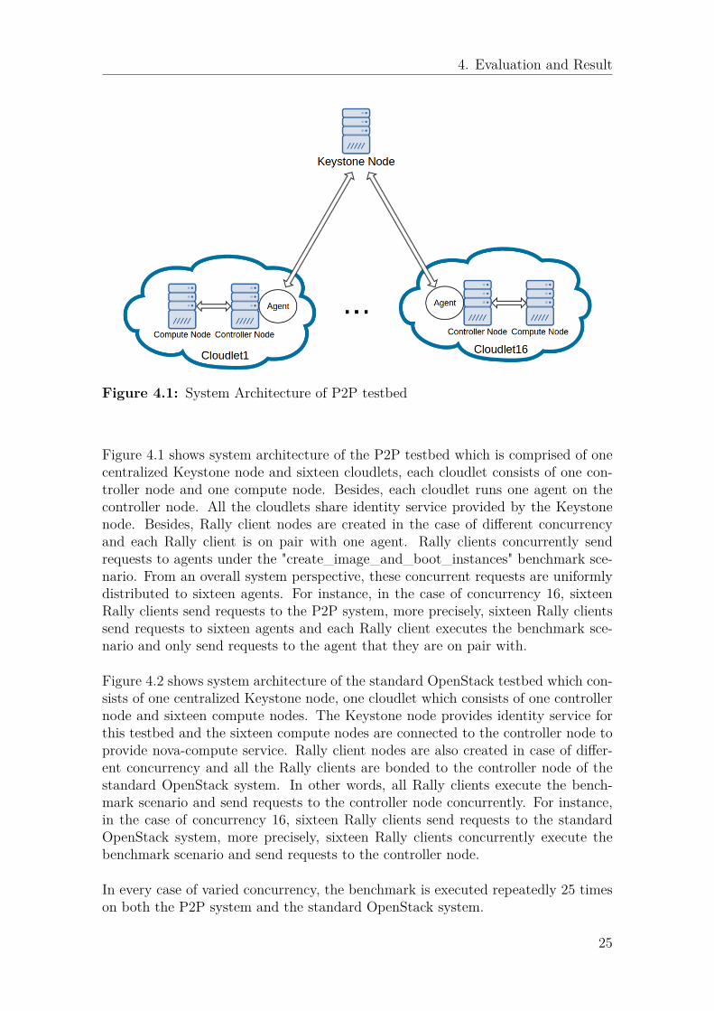
Figure 4.1 shows system architecture of the P2P testbed which is comprised of onecentralized Keystone node and sixteen cloudlets, each cloudlet consists of one con-troller node and one compute node. Besides, each cloudlet runs one agent on thecontroller node. All the cloudlets share identity service provided by the Keystonenode. Besides, Rally client nodes are created in the case of di�erent concurrencyand each Rally client is on pair with one agent. Rally clients concurrently sendrequests to agents under the "create_image_and_boot_instances" benchmark sce-nario. From an overall system perspective, these concurrent requests are uniformlydistributed to sixteen agents. For instance, in the case of concurrency 16, sixteenRally clients send requests to the P2P system, more precisely, sixteen Rally clientssend requests to sixteen agents and each Rally client executes the benchmark sce-nario and only send requests to the agent that they are on pair with.
Figure 4.2 shows system architecture of the standard OpenStack testbed which con-sists of one centralized Keystone node, one cloudlet which consists of one controllernode and sixteen compute nodes. The Keystone node provides identity service forthis testbed and the sixteen compute nodes are connected to the controller node toprovide nova-compute service. Rally client nodes are also created in case of di�er-ent concurrency and all the Rally clients are bonded to the controller node of thestandard OpenStack system. In other words, all Rally clients execute the bench-mark scenario and send requests to the controller node concurrently. For instance,in the case of concurrency 16, sixteen Rally clients send requests to the standardOpenStack system, more precisely, sixteen Rally clients concurrently execute thebenchmark scenario and send requests to the controller node.
In every case of varied concurrency, the benchmark is executed repeatedly 25 timeson both the P2P system and the standard OpenStack system.
25

4. Evaluation and Result
Figure 4.2: System Architecture of Standard testbed
4.2.2 Scenario Two
In scenario two, one P2P testbed is set up at a size of one Keystone node, variednumber of cloudlets. Precisely, each cloudlet is comprised of one controller node, onecompute node and one agent running on the controller node. The P2P testbed isessentially the same as the P2P testbed in scenario one, while system performancein scenario two is aimed to be evaluated regarding varied system size and fixedconcurrency. The fixed concurrency is set as 16 and system size is scaled from 1up to 16. In addition, Rally client nodes are created in the case of di�erent systemsize and each Rally client is on pair with one agent. The benchmark in scenariotwo is the same as the one in scenario one. For every system size, the benchmark isrepeatedly executed 25 times on the P2P testbed.
4.3 Experimental Results and Analysis
This section shows experimental results and analysis of scenario one and scenariotwo separately.
4.3.1 Scenario One
Evaluation results of scenario one are presented and discussed in this subsectionregarding response time, failure rate, CPU usage and distribution of VMs.
26
4. Evaluation and Result
4.3.1.1 Response Time
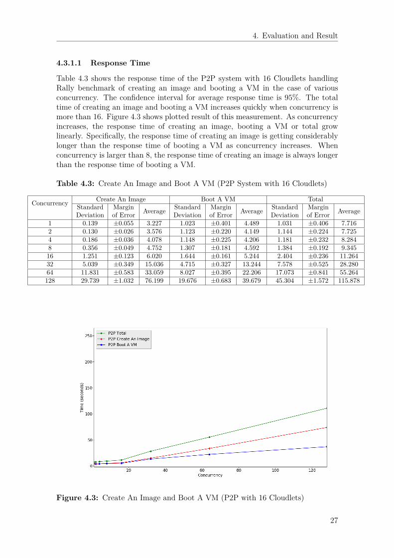
Table 4.3 shows the response time of the P2P system with 16 Cloudlets handlingRally benchmark of creating an image and booting a VM in the case of variousconcurrency. The confidence interval for average response time is 95%. The totaltime of creating an image and booting a VM increases quickly when concurrency ismore than 16. Figure 4.3 shows plotted result of this measurement. As concurrencyincreases, the response time of creating an image, booting a VM or total growlinearly. Specifically, the response time of creating an image is getting considerablylonger than the response time of booting a VM as concurrency increases. Whenconcurrency is larger than 8, the response time of creating an image is always longerthan the response time of booting a VM.
Table 4.3: Create An Image and Boot A VM (P2P System with 16 Cloudlets)
Concurrency Create An Image Boot A VM TotalStandardDeviation
Marginof Error Average Standard
DeviationMarginof Error Average Standard
DeviationMarginof Error Average
1 0.139 ±0.055 3.227 1.023 ±0.401 4.489 1.031 ±0.406 7.7162 0.130 ±0.026 3.576 1.123 ±0.220 4.149 1.144 ±0.224 7.7254 0.186 ±0.036 4.078 1.148 ±0.225 4.206 1.181 ±0.232 8.2848 0.356 ±0.049 4.752 1.307 ±0.181 4.592 1.384 ±0.192 9.34516 1.251 ±0.123 6.020 1.644 ±0.161 5.244 2.404 ±0.236 11.26432 5.039 ±0.349 15.036 4.715 ±0.327 13.244 7.578 ±0.525 28.28064 11.831 ±0.583 33.059 8.027 ±0.395 22.206 17.073 ±0.841 55.264128 29.739 ±1.032 76.199 19.676 ±0.683 39.679 45.304 ±1.572 115.878
Figure 4.3: Create An Image and Boot A VM (P2P with 16 Cloudlets)
27

4. Evaluation and Result
Table 4.4 shows evaluation result of the standard OpenStack with 16 compute nodeshandling Rally benchmark of creating an image and booting a VM in the case ofvarious concurrency. The confidence interval for average response time is 95%.The total time of creating an image and booting a VM increases sharply whenconcurrency is 8. Figure 4.4 shows plotted result of this measurement. The responsetime of booting a VM is always longer than the response time of creating an image.
Table 4.4: Create An Image and Boot A VM (Standard OpenStack with 16 Com-pute Nodes)
Concurrency Create An Image Boot A VM TotalStandardDeviation
Marginof Error Average Standard
DeviationMarginof Error Average Standard
DeviationMarginof Error Average
1 0.085 ±0.033 2.707 0.204 ±0.080 4.122 0.234 ±0.091 6.8292 0.116 ±0.032 2.992 0.405 ±0.112 4.553 0.445 ±0.123 7.5454 0.319 ±0.062 3.148 0.453 ±0.089 6.142 0.587 ±0.115 9.2898 1.008 ±0.139 4.825 1.131 ±0.157 11.132 1.600 ±0.222 15.95716 1.353 ±0.133 10.933 5.414 ±0.531 24.103 6.171 ±0.605 35.03632 6.044 ±0.419 27.843 17.504 ±1.213 49.989 20.722 ±1.436 76.83264 8.565 ±0.422 58.708 31.539 ±1.554 86.636 38.158 ±1.881 145.344128 28.279 ±1.188 113.696 62.687 ±2.632 149.202 81.488 ±3.422 262.898
Figure 4.4: Create An Image and Boot A VM (Standard with 16 Compute Nodes)
Figure 4.5 shows a comparison of the response time of the P2P system with 16cloudlets and standard OpenStack with 16 compute nodes handling Rally bench-mark of creating an image and booting a VM in terms of a various number ofconcurrency. From Figure 4.5, it is obvious that the P2P system performs better
28

4. Evaluation and Result
than the standard OpenStack system as concurrency increases. More precisely, forthe standard OpenStack system, it takes relatively more time handle the wholebenchmark than the P2P system when concurrency grows. Figure 4.5 also showsthat for the standard OpenStack system, when concurrency increases, the perfor-mance of booting a VM markedly a�ect the result of total response time. However,for the P2P system, the response time of booting a VM rises steadily comparedto the standard OpenStack system, the response time of creating an image mainlya�ects the result of total response time instead.
Figure 4.5: Comparison of P2P System and Standard OpenStack Handling Bench-mark of Creating An Image and Booting A VM
4.3.1.2 Failure Rate
Figure 4.6 shows the failure rate of the P2P system and standard OpenStack han-dling Rally benchmark of creating an image and booting a VM in the case of di�erentconcurrency. The failure rate is defined as if the process of booting an image andcreating a VM can be successfully handled by the system. When concurrency is lessthan 64, the failure rate of both systems is 0%. However, both systems start to droprequests when concurrency is 64. When concurrency is up to 128, the failure rateof the standard OpenStack system is significantly higher than the failure rate of theP2P system.
4.3.1.3 CPU Usage
In this measurement, CPU usage of a controller node is periodically recorded every3 seconds. Figure 4.7 demonstrates a comparison of CPU usage of controller node
29

4. Evaluation and Result
Figure 4.6: Failure Rate of P2P System and Standard OpenStack Handling Bench-mark of Creating An Image and Booting A VM
Figure 4.7: Comparison of CPU Usage of P2P Testbed and Standard OpenStackTestbed in Case of Various Concurrency
30

4. Evaluation and Result
of the P2P system and the standard OpenStack system handling Rally benchmarkof creating an image and booting a VM in the case of various concurrency. Asfor the P2P system, the controller node whose a�liated cloudlet is most frequentlychosen to boot VMs at one round of execution is picked to represent CPU usage.From Figure 4.7, it is clear that CPU usages of the controller node of the standardOpenStack system in most cases reach 100% and stay around over a period. Asfor the P2P system, CPU usages of a controller node never reaches 100%, instead,rarely goes above 80% and does not stay around at a high percentage.
Figure 4.8 shows a comparison of CPU usage of controller node of the P2P systemand the standard OpenStack system handling Rally benchmark of creating an imageand booting a VM when concurrency is 128. As for the standard OpenStack system,it is obvious that CPU usage of the controller node quickly goes up to 100% andconstantly remains over a long period until the benchmark is finished. The figureat bottom illustrates CPU usages of all sixteen controller nodes of the P2P systemhandling benchmark of creating an image and booting a VM when concurrency is128. Although CPU usages of controller nodes in the P2P system also quickly goesup, they do not peak at close to 100% and stay around at a high percentage over along period.
Figure 4.8: Comparison of CPU Usage of Controller Nodes in P2P Testbed andStandard OpenStack Testbed in Case of Concurrency 128
4.3.1.4 Distribution of VMs
Figure 4.9 shows the distribution of VMs in the P2P system over 25 times of exe-cution of handling benchmark of creating an image and booting a VM in cases of
31

4. Evaluation and Result
concurrency is 16, 32 and 64. It can be seen that VMs are fairly distributed to var-ious OpenStack cloudlets. There is no striking diversity of VM distribution amongall the OpenStack cloudlets.
Figure 4.9: Distribution of VMs over 25 Times of Handling Benchmark of CreatingAn Image and Booting A VM
4.3.2 Scenario TwoEvaluation results of scenario two are presented and discussed in this subsection interms of response time and CPU usage.
4.3.2.1 Response Time
Table 4.5 shows the response time of the P2P system at various scales handlingRally benchmark of creating an image and booting a VM when concurrency is 16.The confidence interval for average response time is 95%. Figure 4.10 shows plottedresults of this evaluation. It is obvious that the response time of booting a VMdrops significantly when system size scales from one to two which leads to a shorterresponse time of finishing the whole benchmark scenario. As system size scales fromtwo to sixteen, the response time of booting a VM decreases steadily and responsetime of creating an image fluctuates slightly.
4.3.2.2 CPU Usage
In this measurement, CPU usage of a controller node is also periodically recordedevery 3 seconds. Figure 4.11 demonstrates the comparison of CPU usage of controller
32

4. Evaluation and Result
Table 4.5: Create An Image and Boot A VM (P2P System with Varied SystemSize in Case of Concurrency 16)
System Size Create An Image Boot A VM TotalStandardDeviation
Marginof Error Average Standard
DeviationMarginof Error Average Standard
DeviationMarginof Error Average
1 Cloulet 2.274 ±0.322 8.02 6.06 ±0.857 20.714 8.022 ±1.135 28.7352 Cloudlets 1.509 ±0.148 6.096 6.016 ±0.598 10.069 6.716 ±0.658 16.1654 Cloudlets 1.719 ±0.169 7.572 4.046 ±0.397 7.416 4.739 ±0.464 14.9888 Cloudlets 1.077 ±0.106 7.349 2.238 ±0.233 5.883 2.612 ±0.256 13.23216 Cloudlets 1.251 ±0.123 6.020 1.644 ±0.161 5.244 2.404 ±0.236 11.264
Figure 4.10: Response Time in Case of Fixed Concurrency and Varied SystemSize
node of the P2P system handling Rally benchmark of creating an image and bootinga VM in cases of varied system size and concurrency is 16. At one round of execution,the controller node whose a�liated cloudlet is most frequently chosen to boot VMsis picked to represent CPU usage. From Figure 4.11, it can be seen that onlywhen system size is one, CPU usage of controller node goes up to 100% and stayaround for a while then starts fluctuating till benchmark is finished. When systemsize is 2, 4, 8 or 16, CPU usage of chosen controller node just peaks at one pointbut never stay around for a period. When system size is one, the system takes alonger time to handle benchmark of creating an image and booting a VM, as theCPU of controller node is overloaded. Overloaded CPU essentially a�ects systemperformance by taking longer execution time.
From the above measurements, by scaling cloud instances through agents, the pro-
33

4. Evaluation and Result
Figure 4.11: CPU Usage in Cases of Varied System Size and Fixed Number ofConcurrency
posed P2P solution is feasible to create virtual resource across OpenStack cloudinstances and shows significantly lower response time when handles concurrent re-quests by executing request at each OpenStack cloud instance separately and avoid-ing CPU on controller node being overloaded. Moreover, compared to standardOpenStack deployment, the P2P solution is more failure-resistant and e�cient interms of creating an image and booting a VM. Without considering a�ection ofidentity service - Keystone, the P2P solution has no limitation on the number ofcloud instances and its performance improves with the increasing number of cloudinstances.
34
5Future Work
This thesis report has discussed design and implement of a P2P solution for scalingOpenStack cloud instances. Although VMs owned by one project are feasible to becreated on distributed OpenStack cloud instances, these VMs can not functionallycommunicate with each other. Besides, the agent currently only support proxyingOpenStack’s services such as compute service, network service, image service andidentity service. An important next step will be to enrich agent’s functionality byimplementing more proxies for other OpenStack services. Also, the current solutionis not fully distributed, as cloud instances in this P2P network share a centralizedKeystone node which provides identity service. The Keystone node would be a po-tential bottleneck, if the whole P2P system is going to scale massively. Therefore,one important subject of future work will be the replacement of the centralized iden-tity service with a distributed identity service. We envisage this replacement willlead to a better system reliability and performance. Moreover, in the cloud selectionscheduler of our prototype, we kept strategies as simple as possible. Another im-portant subject will be implementing more filters and weighers based on optimizedalgorithms to improve virtual resource utilization. We believe that optimized cloudselection scheduler will bring on better utilization of virtual resources and improvedsystem performance regarding response duration.
35

5. Future Work
36

6Related Work
The problem of scaling cloud instances has been studied for the past decade in bothindustry and academic area. This chapter discusses work related to our study.
Cells is a built-in functionality of Nova which could scale an OpenStack cloud ina more distributed fashion. When this functionality is enabled, compute nodes inan OpenStack cloud are partitioned into groups called Cells [23]. Cells essentiallyprovides the means to create logical fences around OpenStack resources such ascompute nodes. However, Cells is still considered experimental and it’s not an optionfor Ericsson, since Ericsson desires a solution which supports as many OpenStackdefault features as possible, such as Security Group, Availability Zones and ServerGroups in which Cells does not support.
Besides Cells, OpenStack cascading solution is another concept proposed by Huawei[24]. Huawei’s solution is to map the underlying OpenStack to a compute node anduse a parent OpenStack to orchestrate child OpenStack cloud instances. Huawei’sidea is innovative. However, the cascading solution works like fractal [25], it scalesin a hierarchical structure. Due to its attribute, it would be complex and expensiveto implement and manage when the whole cloud system is growing larger. Anotherdrawback of the cascading solution is that, although the child OpenStack cloudinstances are still accessible even if the parent OpenStack cloud instance is down,the consistency will be lost between the parent instance and child instances oncethe parent instance is up again.
Brasileiro et al.[26] present a middleware, called Fogbow, designed to support federa-tions of independent IaaS cloud vendors. Fogbow consists of three main components:membership manager, allocation manager and messaging service. The membershipmanager is for member discover. The allocation manager runs at a given cloud andoperates actions to its a�liated cloud. The messaging service runs at a particularsite and allocation managers and membership managers communicate through thismessaging service. However, no redundancy support for the messaging service whichcould be a single-point failure when the federated system scales up.
In [27], Buyya et al. propose InterCloud framework in which the federated networkof clouds is interceded by a Cloud Exchange. Every cloud runs a Cloud Coordinatorwhich is responsible for publishing o�ers according to the service the cloud provides.The Cloud Brokers requests the required capacity and bids on the o�ers. End usersare associated with a cloud instance, which is responsible for fulfilling user demands.
37
6. Related Work
However, the Cloud Exchange is a potential single-point failure and it leaves eachcloud instance responsible for user identification.
In [28], Celesti et al. introduce a horizontal cross-federation solution based on theCross-Cloud Federation Manager which is a placeable component in cloud infrastruc-ture and consists of three sub-components: discovery agent, match-making agent andauthentication agent. The discovery agent is responsible for discovering all availableforeign clouds, the match-marking agent manages the process of choosing the bestcloud instance to deploy virtual resources and the authentication agent takes dutiesto build security context among federated clouds. However, system performanceevaluation of this solution is not presented and limitation of sharing resources oncloud owner’s demand is still a challenge behind this solution.
[29] and [30] propose the Reservoir virtualization architecture which consists of twomain parts: service provider and infrastructure provider. The service provider leasevirtual resources from infrastructure provider and matches user needs by findingresources that the user’s application requires. The infrastructure provider man-ages physical infrastructure and o�ers pool of resources such as computing capacity,network and storage to service providers. Resources on an infrastructure site arevirtualized and partitioned into virtual execution environments (VEEs). A serviceapplication is capable of using several VEEs across infrastructure providers. How-ever, transfer tasks from one provider to another is still a challenge for Reservoir.
The Contrail project [31] is build on the results of Reservoir project by adding verti-cal integration of PaaS and Iaas models. It provides users with a single access pointto resources belonging to various cloud providers. Contrail acts as a broker betweenusers and cloud provider and it is composed of three layers: interface layer, corelayer and adapters layer. The interface layer exposes a way to interact with the fed-erated systems via CLI and HTTP interfaces. The core layer contains modules thatare responsible for identity management, application deployment and Service LevelAgreement (SLA) coordination. The adapters layer enables access to infrastructureproviders. Whereas, the single access point of Contrail is a potential single-pointfailure.
A layered service model of SaaS, PaaS and IaaS is proposed in [32]. The inter-Cloudfederation is implemented at every service layer and delegated by broker specific tothe entities at that layer. The top SaaS layer handles requirements of executingapplications and maps performance metrics of applications to resources at the PaaSlayer. The PaaS layer represents as a bridge between applications requirementsand infrastructure resources. The IaaS layer provides resources such as computingcapacity, storage and network to layers above it. Information flow between thesethree layers are delegated and translated by brokers. However, the layered modelbrings complexity to the case of scaling horizontally at each layer.
Compared to Huawei’s Cascading solution[24] and the layered service model[32],our proposed solution scales horizontally, no hierarchical relation between cloud in-
38
6. Related Work
stances and system architecture is flat, by which the solution enables cloud instancesto easily join or leave without a�ecting proper functioning. Di�erent from [26] and[31], the centralized Keystone component in our solution is feasible to be redun-dant. In contrast to [27], user identification is handled by the dedicated componentKeystone instead of by each cloud instance in our solution. In [28], limiting sharingresources on cloud owner’s demand is a challenge for the cross-federation solution,conversely, our solution enables cloud owner to elastically share resources. In [29]and [30], the Reservoir has a challenge of transferring tasks from one cloud instanceto another, however, in our solution, tasks of uploading an image or creating a VMis able to be transferred across cloud instances.
39

6. Related Work
40

7Discussion and Conclusion
7.1 Societal and ecological contributionCloud computing is bringing benefits to our lives in many ways. It is a fundamen-tal infrastructure to cutting-edge technologies in areas of Internet of Things, au-tonomous driving, artificial intelligence and others. Besides, cloud providers, suchas Amazon’s AWS, Microsoft’s Azure and Google cloud platform, are becomingmore and more popular with startup companies or small firms as the first choice todeploy their online services. From a societal aspect, by our solution, geographicallydistributed cloud instances are possible to be federated as one and the federatedP2P system is able to be more economic and serve more users with lower cost onbare metals. From an ecological perspective, compared to standard OpenStack de-ployment, our P2P solution needs less machines but behaves more e�cient whichleads to produce less carbon dioxide, consumes less electricity.
7.2 ConclusionWe have presented a solution and its prototype for scaling OpenStack cloud instancesby using P2P technologies. The P2P solution is motivated by a centralized messagequeue of a standard OpenStack cloud instance which causes scalability issue whena number of compute nodes at the cloud instance reaches its limitation. Instead ofsolving this problem by fixing the centralized message queue, we proposed a P2Psolution on cloud cluster level which abstracts multiple OpenStack cloud instancesas one, providing the same user experience as using a single standard OpenStackcloud instance. The abstraction of cloud instances is achieved by deploying a soft-ware agent on each cloud instance which works as a message broker, sitting betweenits a�liated cloud instance and end users. The agent exposes its dedicated APIto end users and maps its API to standard OpenStack service endpoint. Besides,these agents form a P2P network and association of agents is based on an inexpensivegroup membership protocol - Cyclon and distributed search. Our experiment resultsshow that it is feasible to integrate virtual resources across multiple OpenStack cloudinstances while abstracting them as a single cloud instance. Compared to a stan-dard OpenStack deployment with same system size, the proposed P2P solution hashigher failure resistance to certain operations. We conclude that without consider-ing a�ection of the centralized identity service - Keystone, the P2P approach hasno limitation on the number of cloud instances and its performance improves withan increasing number of cloud instances. Also, system performance and resource
41
7. Discussion and Conclusion
utilization of the P2P solution can be enhanced by implementing optimized cloudselection strategies. Replacing the centralized identity service with a distributedsolution remains open for further exploration.
42
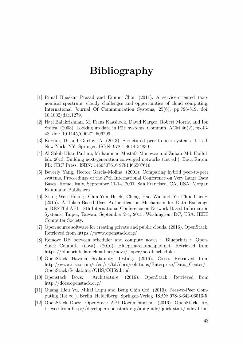
Bibliography
[1] Rimal Bhaskar Prasad and Eunmi Choi. (2011). A service-oriented taxo-nomical spectrum, cloudy challenges and opportunities of cloud computing.International Journal Of Communication Systems, 25(6), pp.796-819. doi:10.1002/dac.1279.
[2] Hari Balakrishnan, M. Frans Kaashoek, David Karger, Robert Morris, and IonStoica. (2003). Looking up data in P2P systems. Commun. ACM 46(2), pp.43-48. doi: 10.1145/606272.606299.
[3] Korzun, D. and Gurtov, A. (2013). Structured peer-to-peer systems. 1st ed.New York, NY: Springer. ISBN: 978-1-4614-5483-0.
[4] Al-Sakib Khan Pathan, Muhammad Mostafa Monowar and Zubair Md. Fadlul-lah. 2013. Building next-generation converged networks (1st ed.). Boca Raton,FL: CRC Press. ISBN: 1466507616 9781466507616.
[5] Beverly Yang, Hector Garcia-Molina. (2001). Comparing hybrid peer-to-peersystems, Proceedings of the 27th International Conference on Very Large DataBases, Rome, Italy, September 11-14, 2001. San Francisco, CA, USA: MorganKaufmann Publishers.
[6] Xiang-Wen Huang, Chin-Yun Hsieh, Cheng Hao Wu and Yu Chin Cheng.(2015). A Token-Based User Authentication Mechanism for Data Exchangein RESTful API, 18th International Conference on Network-Based InformationSystems, Taipei, Taiwan, September 2-4, 2015. Washington, DC, USA: IEEEComputer Society.
[7] Open source software for creating private and public clouds. (2016). OpenStack.Retrieved from https://www.openstack.org/
[8] Remove DB between scheduler and compute nodes : Blueprints : Open-Stack Compute (nova). (2016). Blueprints.launchpad.net. Retrieved fromhttps://blueprints.launchpad.net/nova/+spec/no-db-scheduler
[9] OpenStack Havana Scalability Testing. (2016). Cisco. Retrieved fromhttp://www.cisco.com/c/en/us/td/docs/solutions/Enterprise/Data_Center/OpenStack/Scalability/OHS/OHS2.html
[10] Openstack Docs: Architecture. (2016). OpenStack. Retrieved fromhttp://docs.openstack.org/
[11] Quang Hieu Vu, Mihai Lupu and Beng Chin Ooi. (2010). Peer-to-Peer Com-puting (1st ed.). Berlin, Heidelberg: Springer-Verlag. ISBN: 978-3-642-03513-5.
[12] OpenStack Docs: OpenStack API Documentation. (2016). OpenStack. Re-trieved from http://developer.openstack.org/api-guide/quick-start/index.html
43

Bibliography
[13] Spyros Voulgaris, Daniela Gavidia and Maarten van Steen. (2005). CYCLON:Inexpensive Membership Management for Unstructured P2P Overlays. NetwSyst Manage, 13(2), pp.197-217. doi: 10.1007/s10922-005-4441-x.
[14] Michael Mitzenmacher. (2001). The power of two choices in randomized loadbalancing. IEEE Transactions on Parallel and Distributed Systems, 12(10),pp.1094-1104. Piscataway, NJ, USA: IEEE Press.
[15] SQLAlchemy - The Database Toolkit for Python. (2016). Sqlalchemy.org. Re-trieved from http://www.sqlalchemy.org/
[16] PEP 333 – Python Web Server Gateway Interface v1.0. (2016). Python.org.Retrieved from https://www.python.org/dev/peps/pep-0333/
[17] Eventlet Networking Library. (2016). Eventlet.net. Retrieved fromhttp://eventlet.net/
[18] Libevent – an event notification library. (2016). Libevent.org. Python.org. Re-trieved from http://libevent.org/
[19] Eventlet 0.19.0 Documentation. (2016). Eventlet.net. Retrieved fromhttp://eventlet.net/doc/basic_usage.html
[20] Holger Giese, Stephan Hildebrandt and Leen Lambers. (2012). Bridging thegap between formal semantics and implementation of triple graph grammars.Software and Systems Modeling (SoSyM), 13(1), pp.273-299. Secaucus, NJ,USA: Springer-Verlag New York, Inc.
[21] Memcached - a distributed memory object caching system. (2016). Mem-cached.org. Retrieved from https://memcached.org/
[22] Rally - OpenStack. (2016). Wiki.openstack.org. Retrieved fromhttps://wiki.openstack.org/wiki/Rally
[23] OpenStack Docs: OpenStack Operations Guide. (2016). Docs.openstack.org.Retrieved from http://docs.openstack.org/openstack-ops/content/scaling.html
[24] OpenStack cascading solution - OpenStack. (2016). Wiki.openstack.org. Re-trieved from https://wiki.openstack.org/wiki/OpenStack_cascading_solution
[25] Nathan Lazarus, Christopher D. Meyer and Sarah S. Bedair. (2014). FractalInductors. IEEE Transactions on Magnetics, 50(4), pp.1-8. doi: 10.1109/T-MAG.2013.2290510.
[26] Francisco Brasileiro, Giovanni Silva, Francisco Araújo, Marcos Nóbrega, IgorSilva and Gustavo Rocha. (2016). Fogbow: A Middleware for the Federationof IaaS Clouds. 2016 16th IEEE/ACM International Symposium on Cluster,Cloud and Grid Computing (CCGrid), Cartagena, Colombia, May 16-19, 2016.Piscataway, NJ, USA: IEEE Press.
[27] Rajkumar Buyya, Rajiv Ranjan and Rodrigo N. Calheiros. (2010). InterCloud:Utility-Oriented Federation of Cloud Computing Environments for Scaling ofApplication Services. Proceedings of the 10th international conference on Al-gorithms and Architectures for Parallel Processing, 1, pp.13-31. Berlin, Heidel-berg: Springer-Verlag. doi: 10.1007/978-3-642-13119-6_2.
[28] Antonio Celesti, Francesco Tusa, Massimo Villari and Antonio Puliafito. (2010).How to Enhance Cloud Architectures to Enable Cross-Federation. 2010 IEEE3rd International Conference on Cloud Computing, Miami, Florida, USA, July5-10, 2010. Piscataway, NJ, USA: IEEE Press.
44

Bibliography
[29] Benny Rochwerger, David Breitgand, Eliezer Levy, Alex Galis, Kenneth Na-gin, Ignacio M. Llorente, Rubén Santiago Montero, Yaron Wolfsthal, Erik Elm-roth, Juan A. Cáceres, M. Ben-Yehuda, Wolfgang Emmerich and Fermín Galán.(2009). The Reservoir model and architecture for open federated cloud comput-ing. IBM Journal of Research and Development, 53(4), pp.4:1-4:11. Riverton,NJ, USA: IBM Corp.
[30] Benny Rochwerger, David Breitgand, Amir Epstein, David Hadas, Irit Loy,Kenneth Nagin, Johan Tordsson, Carmelo Ragusa, Massimo Villari, StuartClayman, Eliezer Levy, Alessandro Maraschini, Philippe Massonet, HenarMunoz and Giovanni Tofetti. (2011). Reservoir - When One Cloud Is NotEnough. Computer, 44(3), pp.44-51. Los Alamitos, CA, USA: IEEE ComputerSociety Press.
[31] Emanuele Carlini, Massimo Coppola, Patrizio Dazzi, Laura Ricci and GiacomoRighetti. (2011). Cloud Federations in Contrail. Proceedings of the 2011 in-ternational conference on Parallel Processing, pp.159–168. Berlin, Heidelberg:Springer-Verlag.
[32] David Villegas, Norman Bobro�, Ivan Rodero, Javier Delgado, Yanbin Liu,Aditya Devarakonda, Liana Fong, S. Masoud Sadjadi, Manish Parashar. Cloudfederation in a layered service model. Journal of Computer and System Sciences,78(5), pp.1330–1344. Orlando, FL, USA: Academic Press.
45