SCALANCE XM-400/XR-500 Web Based Management (WBM… · Configuring with Web Based ... SCALANCE...
420
SCALANCE XM-400/XR-500 Web Based Management (WBM) ___________________ ___________________ ___________________ ___________________ ___________________ ___________________ SIMATIC NET Industrial Ethernet switches SCALANCE XM-400/XR-500 Web Based Management (WBM) Configuration Manual 11/2015 C79000-G8976-C248-10 Introduction 1 Description 2 IP addresses 3 Technical basics 4 Configuring with Web Based Management 5 Troubleshooting/FAQ 6
Transcript of SCALANCE XM-400/XR-500 Web Based Management (WBM… · Configuring with Web Based ... SCALANCE...

SCALANCE XM-400/XR-500 Web
Based Management (WBM)
___________________
___________________
___________________
___________________
___________________
___________________
SIMATIC NET
Industrial Ethernet switches SCALANCE XM-400/XR-500 Web Based Management (WBM)
Configuration Manual
11/2015 C79000-G8976-C248-10
Introduction 1
Description 2
IP addresses 3
Technical basics 4
Configuring with Web Based Management
5
Troubleshooting/FAQ 6

Siemens AG Division Process Industries and Drives Postfach 48 48 90026 NÜRNBERG GERMANY
C79000-G8976-C248-10 Ⓟ 11/2015 Subject to change
Copyright © Siemens AG 2011 - 2015. All rights reserved
Legal information Warning notice system
This manual contains notices you have to observe in order to ensure your personal safety, as well as to prevent damage to property. The notices referring to your personal safety are highlighted in the manual by a safety alert symbol, notices referring only to property damage have no safety alert symbol. These notices shown below are graded according to the degree of danger.
DANGER indicates that death or severe personal injury will result if proper precautions are not taken.
WARNING indicates that death or severe personal injury may result if proper precautions are not taken.
CAUTION indicates that minor personal injury can result if proper precautions are not taken.
NOTICE indicates that property damage can result if proper precautions are not taken.
If more than one degree of danger is present, the warning notice representing the highest degree of danger will be used. A notice warning of injury to persons with a safety alert symbol may also include a warning relating to property damage.
Qualified Personnel The product/system described in this documentation may be operated only by personnel qualified for the specific task in accordance with the relevant documentation, in particular its warning notices and safety instructions. Qualified personnel are those who, based on their training and experience, are capable of identifying risks and avoiding potential hazards when working with these products/systems.
Proper use of Siemens products Note the following:
WARNING Siemens products may only be used for the applications described in the catalog and in the relevant technical documentation. If products and components from other manufacturers are used, these must be recommended or approved by Siemens. Proper transport, storage, installation, assembly, commissioning, operation and maintenance are required to ensure that the products operate safely and without any problems. The permissible ambient conditions must be complied with. The information in the relevant documentation must be observed.
Trademarks All names identified by ® are registered trademarks of Siemens AG. The remaining trademarks in this publication may be trademarks whose use by third parties for their own purposes could violate the rights of the owner.
Disclaimer of Liability We have reviewed the contents of this publication to ensure consistency with the hardware and software described. Since variance cannot be precluded entirely, we cannot guarantee full consistency. However, the information in this publication is reviewed regularly and any necessary corrections are included in subsequent editions.
SCALANCE XM-400/XR-500 Web Based Management (WBM) Configuration Manual, 11/2015, C79000-G8976-C248-10 3
Table of contents
1 Introduction ............................................................................................................................................. 9
1.1 Information on this configuration manual .................................................................................. 9
2 Description ............................................................................................................................................ 13
2.1 Product characteristics............................................................................................................ 13
2.2 Requirements for installation and operation ........................................................................... 15
2.3 C-PLUG / KEY-PLUG ............................................................................................................. 16
2.4 Power over Ethernet (PoE) ..................................................................................................... 18
3 IP addresses ......................................................................................................................................... 21
3.1 IPv4 / IPv6 ............................................................................................................................... 21
3.2 IPv4 address ........................................................................................................................... 23 3.2.1 Structure of an IPv4 address .................................................................................................. 23 3.2.2 Initial assignment of an IPv4 address ..................................................................................... 24 3.2.3 Address assignment with DHCP ............................................................................................. 25
3.3 IPv6 addresses ....................................................................................................................... 27 3.3.1 IPv6 terms ............................................................................................................................... 27 3.3.2 Structure of an IPv6 address .................................................................................................. 28
4 Technical basics ................................................................................................................................... 31
4.1 Configuration limits ................................................................................................................. 31
4.2 VLAN ....................................................................................................................................... 33 4.2.1 VLAN tagging .......................................................................................................................... 34
4.3 SNMP ...................................................................................................................................... 36
4.4 Routing function ...................................................................................................................... 38 4.4.1 Static routing ........................................................................................................................... 38 4.4.2 VRRP ...................................................................................................................................... 39 4.4.2.1 VRRPv2 .................................................................................................................................. 39 4.4.2.2 VRRP3 .................................................................................................................................... 39 4.4.3 OSPF ...................................................................................................................................... 40 4.4.3.1 OSPFv2 .................................................................................................................................. 40 4.4.3.2 OSPFv3 .................................................................................................................................. 44 4.4.4 RIP .......................................................................................................................................... 45 4.4.4.1 RIPv2 ...................................................................................................................................... 45 4.4.4.2 RIPng ...................................................................................................................................... 46
4.5 Redundancy mechanism ........................................................................................................ 47 4.5.1 Spanning Tree ........................................................................................................................ 47 4.5.1.1 RSTP, MSTP, CIST ................................................................................................................ 48 4.5.2 HRP......................................................................................................................................... 49 4.5.3 MRP ........................................................................................................................................ 49 4.5.3.1 MRP - Media Redundancy Protocol ....................................................................................... 49

Table of contents
SCALANCE XM-400/XR-500 Web Based Management (WBM) 4 Configuration Manual, 11/2015, C79000-G8976-C248-10
4.5.3.2 Configuration in WBM ............................................................................................................ 52 4.5.3.3 Configuration in STEP 7 ........................................................................................................ 53 4.5.4 Standby .................................................................................................................................. 56
4.6 Link aggregation..................................................................................................................... 58
5 Configuring with Web Based Management ............................................................................................ 59
5.1 Web Based Management ...................................................................................................... 59
5.2 Login ...................................................................................................................................... 61
5.3 The "Information" menu ......................................................................................................... 64 5.3.1 Start page ............................................................................................................................... 64 5.3.2 Versions ................................................................................................................................. 69 5.3.3 Identification & Maintenance .................................................................................................. 70 5.3.4 ARP / Neighbors .................................................................................................................... 72 5.3.4.1 ARP Table .............................................................................................................................. 72 5.3.4.2 IPv6 Neighbor Table .............................................................................................................. 73 5.3.5 Log Table ............................................................................................................................... 74 5.3.6 Faults ..................................................................................................................................... 76 5.3.7 Redundancy ........................................................................................................................... 77 5.3.7.1 Spanning Tree........................................................................................................................ 77 5.3.7.2 VRRP statistics ...................................................................................................................... 80 5.3.7.3 VRRP Statistics ...................................................................................................................... 83 5.3.7.4 Ring redundancy .................................................................................................................... 85 5.3.7.5 Standby .................................................................................................................................. 87 5.3.8 Ethernet Statistics .................................................................................................................. 89 5.3.8.1 Interface Statistics .................................................................................................................. 89 5.3.8.2 Packet Size ............................................................................................................................ 90 5.3.8.3 Frame Type ............................................................................................................................ 91 5.3.8.4 Packet Error ........................................................................................................................... 92 5.3.8.5 History .................................................................................................................................... 94 5.3.9 Unicast ................................................................................................................................... 95 5.3.10 Multicast ................................................................................................................................. 96 5.3.11 LLDP ...................................................................................................................................... 98 5.3.12 Fiber Monitoring Protocol ....................................................................................................... 99 5.3.13 IPv4 routing .......................................................................................................................... 101 5.3.13.1 Routing Table ....................................................................................................................... 101 5.3.13.2 OSPFv2 Interfaces ............................................................................................................... 102 5.3.13.3 OSPFv2 Neighbors .............................................................................................................. 103 5.3.13.4 OSPFv2 Virtual Neighbors ................................................................................................... 105 5.3.13.5 OSPFv2 LSDB ..................................................................................................................... 107 5.3.13.6 RIPv2 Statistics .................................................................................................................... 108 5.3.14 IPv6 routing .......................................................................................................................... 109 5.3.14.1 IPv6 Routing Table .............................................................................................................. 109 5.3.14.2 OSPFv3 Interfaces ............................................................................................................... 110 5.3.14.3 OSPFv3 Neighbors .............................................................................................................. 112 5.3.14.4 OSPFv3 Virtual Neighbors ................................................................................................... 114 5.3.14.5 OSPFv3 AS-Scope LSDB .................................................................................................... 116 5.3.14.6 OSPFv3 Area-Scope LSDB ................................................................................................. 117 5.3.14.7 OSPFv3 Link-Scope LSDB .................................................................................................. 119 5.3.14.8 RIPng Statistics .................................................................................................................... 120 5.3.15 SNMP ................................................................................................................................... 121 5.3.16 Security ................................................................................................................................ 122

Table of contents
SCALANCE XM-400/XR-500 Web Based Management (WBM) Configuration Manual, 11/2015, C79000-G8976-C248-10 5
5.3.16.1 Overview ............................................................................................................................... 122 5.3.16.2 Supported Function Rights ................................................................................................... 125 5.3.16.3 Roles ..................................................................................................................................... 126 5.3.16.4 Groups .................................................................................................................................. 127
5.4 The "System" menu .............................................................................................................. 128 5.4.1 Configuration ......................................................................................................................... 128 5.4.2 General ................................................................................................................................. 131 5.4.2.1 Device ................................................................................................................................... 131 5.4.2.2 Coordinates ........................................................................................................................... 132 5.4.3 Agent IP ................................................................................................................................ 133 5.4.4 DNS....................................................................................................................................... 134 5.4.5 Restart .................................................................................................................................. 136 5.4.6 Load & Save ......................................................................................................................... 137 5.4.6.1 HTTP ..................................................................................................................................... 137 5.4.6.2 TFTP ..................................................................................................................................... 141 5.4.6.3 Passwords ............................................................................................................................ 144 5.4.7 Events ................................................................................................................................... 145 5.4.7.1 Configuration ......................................................................................................................... 145 5.4.7.2 Severity Filters ...................................................................................................................... 148 5.4.8 SMTP client ........................................................................................................................... 149 5.4.9 DHCP client .......................................................................................................................... 151 5.4.10 SNMP .................................................................................................................................... 152 5.4.10.1 General ................................................................................................................................. 152 5.4.10.2 Traps ..................................................................................................................................... 154 5.4.10.3 v3 Groups ............................................................................................................................. 155 5.4.10.4 v3 users ................................................................................................................................ 157 5.4.11 System Time ......................................................................................................................... 159 5.4.11.1 Manual Setting ...................................................................................................................... 160 5.4.11.2 DST Overview ....................................................................................................................... 162 5.4.11.3 DST Configuration ................................................................................................................ 164 5.4.11.4 SNTP Client .......................................................................................................................... 168 5.4.11.5 NTP Client ............................................................................................................................. 171 5.4.11.6 SIMATIC time client .............................................................................................................. 173 5.4.11.7 PTP Client ............................................................................................................................. 174 5.4.11.8 PTP Client ............................................................................................................................. 174 5.4.12 Automatic logout ................................................................................................................... 176 5.4.13 Configuration of the SELECT/SET button ............................................................................ 177 5.4.14 Syslog Client ......................................................................................................................... 179 5.4.15 Ports ...................................................................................................................................... 181 5.4.15.1 Overview ............................................................................................................................... 181 5.4.15.2 Configuration ......................................................................................................................... 185 5.4.16 Fault Monitoring .................................................................................................................... 189 5.4.16.1 Power Supply ........................................................................................................................ 189 5.4.16.2 Link Change .......................................................................................................................... 191 5.4.16.3 Redundancy .......................................................................................................................... 193 5.4.17 PNIO ..................................................................................................................................... 193 5.4.18 PLUG .................................................................................................................................... 194 5.4.18.1 Configuration ......................................................................................................................... 194 5.4.18.2 License .................................................................................................................................. 197 5.4.19 Ping ....................................................................................................................................... 199 5.4.20 PoE ....................................................................................................................................... 200 5.4.20.1 General ................................................................................................................................. 200

Table of contents
SCALANCE XM-400/XR-500 Web Based Management (WBM) 6 Configuration Manual, 11/2015, C79000-G8976-C248-10
5.4.20.2 Port ....................................................................................................................................... 202 5.4.21 Port Diagnostics ................................................................................................................... 205 5.4.21.1 Cable Tester ......................................................................................................................... 205 5.4.21.2 SFP diagnostics ................................................................................................................... 207
5.5 The "Layer 2" menu ............................................................................................................. 209 5.5.1 Configuration ........................................................................................................................ 209 5.5.2 QoS ...................................................................................................................................... 213 5.5.2.1 CoS queue mapping ............................................................................................................ 213 5.5.2.2 DSCP Mapping .................................................................................................................... 215 5.5.2.3 QoS Trust ............................................................................................................................. 216 5.5.3 Rate Control ......................................................................................................................... 218 5.5.4 VLAN .................................................................................................................................... 220 5.5.4.1 General ................................................................................................................................ 220 5.5.4.2 GVRP ................................................................................................................................... 223 5.5.4.3 Port-based VLAN ................................................................................................................. 225 5.5.4.4 Protocol-based VLAN group ................................................................................................ 227 5.5.4.5 Protocol-based VLAN port ................................................................................................... 228 5.5.4.6 IPv4 subnet-based VLAN ..................................................................................................... 230 5.5.5 Mirroring ............................................................................................................................... 231 5.5.5.1 General ................................................................................................................................ 232 5.5.5.2 Port ....................................................................................................................................... 237 5.5.5.3 VLAN .................................................................................................................................... 238 5.5.5.4 MAC Flow ............................................................................................................................. 239 5.5.5.5 IP Flow ................................................................................................................................. 240 5.5.6 Dynamic MAC Aging ............................................................................................................ 241 5.5.7 Ring redundancy .................................................................................................................. 242 5.5.7.1 Ring ...................................................................................................................................... 242 5.5.7.2 Standby ................................................................................................................................ 245 5.5.8 Spanning tree ....................................................................................................................... 248 5.5.8.1 General ................................................................................................................................ 248 5.5.8.2 CIST General ....................................................................................................................... 249 5.5.8.3 CIST Port ............................................................................................................................. 251 5.5.8.4 MST General ........................................................................................................................ 255 5.5.8.5 MST Port .............................................................................................................................. 256 5.5.8.6 Enhanced Passive Listening Compatibility .......................................................................... 259 5.5.9 Loop Detection ..................................................................................................................... 261 5.5.10 Link aggregation................................................................................................................... 263 5.5.11 DCP forwarding .................................................................................................................... 266 5.5.12 LLDP .................................................................................................................................... 268 5.5.13 Fiber Monitoring Protocol ..................................................................................................... 269 5.5.14 Unicast ................................................................................................................................. 271 5.5.14.1 Filtering ................................................................................................................................ 271 5.5.14.2 Locked ports ......................................................................................................................... 273 5.5.14.3 Learning ............................................................................................................................... 275 5.5.14.4 Unicast blocking ................................................................................................................... 276 5.5.15 Multicast ............................................................................................................................... 277 5.5.15.1 Groups ................................................................................................................................. 277 5.5.15.2 IGMP .................................................................................................................................... 280 5.5.15.3 GMRP .................................................................................................................................. 282 5.5.15.4 Multicast blocking ................................................................................................................. 284 5.5.15.5 MLD (IPv6) ........................................................................................................................... 285 5.5.16 Broadcast ............................................................................................................................. 287

Table of contents
SCALANCE XM-400/XR-500 Web Based Management (WBM) Configuration Manual, 11/2015, C79000-G8976-C248-10 7
5.5.17 PTP ....................................................................................................................................... 289 5.5.17.1 General ................................................................................................................................. 289 5.5.17.2 TC General ........................................................................................................................... 290 5.5.17.3 TC Port .................................................................................................................................. 290 5.5.18 RMON ................................................................................................................................... 292 5.5.18.1 Statistics ................................................................................................................................ 292 5.5.18.2 History ................................................................................................................................... 293
5.6 The "Layer 3 (IPv4)" menu.................................................................................................... 295 5.6.1 Configuration ......................................................................................................................... 295 5.6.2 Subnets ................................................................................................................................. 296 5.6.2.1 Overview ............................................................................................................................... 296 5.6.2.2 Configuration ......................................................................................................................... 299 5.6.3 Static Routes ......................................................................................................................... 300 5.6.4 Route Maps ........................................................................................................................... 302 5.6.4.1 General ................................................................................................................................. 302 5.6.4.2 Interface & Value Match........................................................................................................ 303 5.6.4.3 Destination Match ................................................................................................................. 305 5.6.4.4 Next Hop Match .................................................................................................................... 305 5.6.4.5 Create ................................................................................................................................... 306 5.6.5 DHCP Relay Agent ............................................................................................................... 307 5.6.5.1 General ................................................................................................................................. 307 5.6.5.2 Option ................................................................................................................................... 309 5.6.6 VRRP .................................................................................................................................... 311 5.6.6.1 Router ................................................................................................................................... 311 5.6.6.2 Configuration ......................................................................................................................... 314 5.6.6.3 Address overview .................................................................................................................. 315 5.6.6.4 Address Configuration .......................................................................................................... 316 5.6.7 VRRPv3 ................................................................................................................................ 317 5.6.7.1 Router ................................................................................................................................... 317 5.6.7.2 Configuration ......................................................................................................................... 320 5.6.7.3 Addresses Overview ............................................................................................................. 322 5.6.7.4 Addresses Configuration ...................................................................................................... 323 5.6.8 OSPFv2 ................................................................................................................................ 324 5.6.8.1 Configuration ......................................................................................................................... 324 5.6.8.2 Areas ..................................................................................................................................... 326 5.6.8.3 Area Range ........................................................................................................................... 327 5.6.8.4 Interfaces .............................................................................................................................. 329 5.6.8.5 Interface Authentication ........................................................................................................ 331 5.6.8.6 Virtual Links .......................................................................................................................... 333 5.6.8.7 Virtual Link Authentication .................................................................................................... 335 5.6.9 RIPv2 .................................................................................................................................... 337 5.6.9.1 Configuration ......................................................................................................................... 337 5.6.9.2 Interfaces .............................................................................................................................. 338
5.7 The "Layer 3 (IPv6)" menu.................................................................................................... 340 5.7.1 Configuration ......................................................................................................................... 340 5.7.2 Subnets ................................................................................................................................. 341 5.7.3 DHCPv6 client ....................................................................................................................... 343 5.7.3.1 DHCPv6 client ....................................................................................................................... 343 5.7.3.2 DHCPv6 PD Sub Client ........................................................................................................ 344 5.7.4 Static Routes ......................................................................................................................... 346 5.7.5 Route maps ........................................................................................................................... 348

Table of contents
SCALANCE XM-400/XR-500 Web Based Management (WBM) 8 Configuration Manual, 11/2015, C79000-G8976-C248-10
5.7.5.1 General ................................................................................................................................ 348 5.7.5.2 Interface & Value Match ....................................................................................................... 349 5.7.5.3 Destination Match ................................................................................................................ 351 5.7.5.4 Next-Hop filtern .................................................................................................................... 351 5.7.5.5 Einstellen ............................................................................... Fehler! Textmarke nicht definiert. 5.7.6 DHCPv4 Relay Agent .......................................................................................................... 354 5.7.6.1 Interfaces ............................................................................................................................. 354 5.7.6.2 Server Addresses................................................................................................................. 356 5.7.6.3 Outgoing Interfaces .............................................................................................................. 357 5.7.7 VRRPv3 ............................................................................................................................... 358 5.7.7.1 Routers ................................................................................................................................. 358 5.7.7.2 Configuration ........................................................................................................................ 360 5.7.7.3 Addresses Overview ............................................................................................................ 362 5.7.7.4 Addresses Configuration ...................................................................................................... 363 5.7.8 OSPFv3 ................................................................................................................................ 364 5.7.8.1 Configuration ........................................................................................................................ 364 5.7.8.2 Areas .................................................................................................................................... 366 5.7.8.3 Area ...................................................................................................................................... 368 5.7.8.4 Interfaces ............................................................................................................................. 370 5.7.8.5 Virtual Links .......................................................................................................................... 372 5.7.9 RIPng ................................................................................................................................... 374 5.7.9.1 RIPng Configuration ............................................................................................................. 374 5.7.9.2 RIPng interfaces................................................................................................................... 376
5.8 The "Security" menu ............................................................................................................ 377 5.8.1 User management ............................................................................................................... 377 5.8.2 Users .................................................................................................................................... 380 5.8.2.1 Roles .................................................................................................................................... 380 5.8.2.2 Groups ................................................................................................................................. 382 5.8.2.3 Local Users .......................................................................................................................... 384 5.8.3 Passwords ............................................................................................................................ 387 5.8.4 AAA ...................................................................................................................................... 389 5.8.4.1 General ................................................................................................................................ 389 5.8.4.2 RADIUS Client ..................................................................................................................... 390 5.8.4.3 802.1x Authenticator ............................................................................................................ 393 5.8.5 MAC ACL ............................................................................................................................. 397 5.8.5.1 Rules Configuration ............................................................................................................. 397 5.8.5.2 Ingress Rules ....................................................................................................................... 398 5.8.5.3 Egress Rules ........................................................................................................................ 400 5.8.6 IP ACL .................................................................................................................................. 401 5.8.6.1 Rules Configuration ............................................................................................................. 401 5.8.6.2 Protocol Configuration ......................................................................................................... 403 5.8.6.3 Ingress Rules ....................................................................................................................... 404 5.8.6.4 Egress Rules ........................................................................................................................ 407 5.8.7 Management ACL ................................................................................................................ 410
6 Troubleshooting/FAQ ........................................................................................................................... 413
6.1 Firmware update via WBM or CLI not possible ................................................................... 413
Index ................................................................................................................................................... 415

SCALANCE XM-400/XR-500 Web Based Management (WBM) Configuration Manual, 11/2015, C79000-G8976-C248-10 9
Introduction 1 1.1 Information on this configuration manual
Validity of the configuration manual This Configuration Manual covers the following products:
● SCALANCE XR-500
– SCALANCE XR524-8C
– SCALANCE XR526-8C
– SCALANCE XR528-6M
– SCALANCE XR552-12M
The devices are available with or without routing functions. The routing function can either be integrated in the devices or made available with a key plug.
● SCALANCE XM-400
– SCALANCE XM408-4C
– SCALANCE XM408-8C
– SCALANCE XM416-4C
The devices are available with or without routing functions. The routing function can either be integrated in the devices or made available with a key plug.
This Configuration Manual applies to the following software version:
● SCALANCE XR-500 firmware as of version 5.1
● SCALANCE XM-400 firmware as of version 5.1
Purpose of the Configuration Manual This Configuration Manual is intended to provide you with the information you require to install, commission and operate IE switches. It provides you with the information you require to configure the IE switches.

Introduction 1.1 Information on this configuration manual
SCALANCE XM-400/XR-500 Web Based Management (WBM) 10 Configuration Manual, 11/2015, C79000-G8976-C248-10
Orientation in the documentation Apart from this configuration manual, the products also have the following documentation:
● Configuration Manual:
– SCALANCE XM-400/XR-500 Command Line Interface (CLI)
This document contains the CLI commands that are supported by the IE switches SCALANCE XM-400 and SCALANCE X-500.
● Operating instructions:
– SCALANCE XR-500
– MM900 media modules for SCALANCE XR-500M
– Fan unit FAN597-1 for SCALANCE XR-500M
– Power supply PS598-1 for SCALANCE XR-500M
– SCALANCE XM-400
– Extender for SCALANCE XM-400
– Pluggable transceiver SFP/SFP+/SCP/STP
– PoE power supply SCALANCE PS9230 PoE / SCALANCE PS924 PoE
These documents contain information on installing and connecting up and approvals for the products.
The following documentation is also available from SIMATIC NET on the topic of Industrial Ethernet:
● System manual "Industrial Ethernet / PROFINET"
● System manual "Industrial Ethernet / PROFINET - Passive network components"
All these documents are available on the SCALANCE X DVD.
Terms used The designation . . . stands for . . . IE switch Industrial Ethernet switch IPv4 address IPv4 address IPv6 address IPv6 address IP address IPv4 / IPv6 address IPv4 interface Interface that supports IPv4. IPv6 interface Interface that supports IPv6. The interface can have more
than one IPv6 address The IPv6 addresses have different ranges (scope), e.g. link local
IP interface Interface that supports both IPv4 and IPv6. As default the IPv4 support is already activated. The IPv6 support needs to be activated extra.

Introduction 1.1 Information on this configuration manual
SCALANCE XM-400/XR-500 Web Based Management (WBM) Configuration Manual, 11/2015, C79000-G8976-C248-10 11
What's new as of version 5.1? Below, you will find an overview of the most important function expansions:
● Configuration of IPv6 functionalities.
– Information > IPv6 routing
– Information > ARP / Neighbors > IPv6 Neighbor Table
– Information > Redundancy > VRRPv3 Statistics
– Layer 2 > Multicast > MLD
– Layer 3 (IPv4) > VRRPv3
– Layer 3 (IPv6)
● Managing user accounts
– Information > Security
– Security > User Accounts
● Fiber Monitoring
– Information > FMP
– Layer 2 > FMP
SIMATIC NET glossary Explanations of many of the specialist terms used in this documentation can be found in the SIMATIC NET glossary.
You will find the SIMATIC NET glossary here:
● SIMATIC NET Manual Collection or product DVD
The DVD ships with certain SIMATIC NET products.
● On the Internet under the following address:
50305045 (http://support.automation.siemens.com/WW/view/en/50305045)
Security information Siemens provides products and solutions with industrial security functions that support the secure operation of plants, solutions, machines, equipment and/or networks. They are important components in a holistic industrial security concept. With this in mind, Siemens’ products and solutions undergo continuous development. Siemens recommends strongly that you regularly check for product updates.
For the secure operation of Siemens products and solutions, it is necessary to take suitable preventive action (e.g. cell protection concept) and integrate each component into a holistic, state-of-the-art industrial security concept. Third-party products that may be in use should also be considered. For more information about industrial security, visit http://www.siemens.com/industrialsecurity.
To stay informed about product updates as they occur, sign up for a product-specific newsletter. For more information, visit http://support.automation.siemens.com.

Introduction 1.1 Information on this configuration manual
SCALANCE XM-400/XR-500 Web Based Management (WBM) 12 Configuration Manual, 11/2015, C79000-G8976-C248-10
License conditions
Note Open source software
Read the license conditions for open source software carefully before using the product.
You will find license conditions in the following documents on the supplied data medium:
● DOC_OSS-SCALANCE-X_74.pdf
● DC_LicenseSummaryScalanceXM400_76.pdf
● DC_LicenseSummaryScalanceXR500_76.pdf
You will find these documents on the product DVD in the following directory: /Open Source Information
Trademarks The following and possibly other names not identified by the registered trademark sign ® are registered trademarks of Siemens AG:
SIMATIC NET, SCALANCE, C-PLUG, OLM
Firmware The firmware is signed and encrypted. This ensures that only firmware created by Siemens can be downloaded to the device.

SCALANCE XM-400/XR-500 Web Based Management (WBM) Configuration Manual, 11/2015, C79000-G8976-C248-10 13
Description 2 2.1 Product characteristics
Properties of the IE switches ● The Ethernet interfaces support the following modes:
– 10 Mbps and 100 Mbps both in full and half duplex
– 1000 Mbps full duplex
– Autocrossing
– Autopolarity
● Redundancy protocols Multiple Spanning Tree Protocol (MSTP), Rapid Spanning Tree Protocol (RSTP) and Spanning Tree Protocol (STP)
This means part of a network can be connected redundantly to a higher-level company network. The reconfiguration time of the network is in the seconds range and therefore takes longer than the ring redundancy method.
● Virtual networks (VLAN)
To structure Industrial Ethernet networks with a fast growing number of nodes, a physical network can be divided into several virtual subnets. Port-based, protocol-based and subnet-based VLANs are available.
● Load limitation when using multicast protocols, for example video transmission By learning the multicast sources and destinations (IGMP snooping, IGMP querier), the IE switches can filter multicast data traffic and limit the load in the network. Multicast and broadcast data traffic can be limited.
● Time-of-day synchronization
Diagnostics messages (log table entries, e-mails) are given a time stamp. The local time is uniform throughout the network thanks to synchronization with a SICLOCK time transmitter or SNTP/NTP/PTP server and therefore makes the identification of diagnostics messages of several devices easier.
● Link aggregation (IEEE 802.1AX) for bundling ports
● Quality of Service for classification of the network traffic is according to COS (Class of Service - IEEE 802.11Q) and DSCP (Differentiated Services Code Point - RFC 2474)
Layer 3 functions The following functions are only available on devices with routing functions:
● Static routing
● OSPF / OSPFv3

Description 2.1 Product characteristics
SCALANCE XM-400/XR-500 Web Based Management (WBM) 14 Configuration Manual, 11/2015, C79000-G8976-C248-10
● VRRP / VRRPv3
● RIP / RIPng
There are devices that natively support all routing functions. You will find the order numbers in the operating instructions of the devices.
On the devices that only support layer 2, you can enable the routing functions with a KEY-PLUG.
IPv6 addresses As of firmware version 5.0 you can configure IPv6 functionalities using the Command Line Interface. As of firmware version 5.1 you can configure IPv6 functionalities in the Web Based Management. You can recognize IPv6 addresses by the name "Subnet Mask/Prefix2.
Naming interfaces Interface names with SCALANCE XM-400
● Interfaces of the basic device
The interfaces of the basic device SCALANCE XM-400 are called module 1.
● Interfaces of extenders
The port extenders are called module 2 and module 3 starting from the basic device. The number of port extenders depends on the number of ports of the basic device.
The extender function is called module 0.
Interface names with SCALANCE XR-500
● Permanently integrated Interfaces
The interfaces permanently installed in the SCALANCE XR-500 are identified with module 0.
● Interfaces of modules
The slots for modules are called module 1 followed by numbers. The numbering range depends on the hardware configuration. The numbering is fixed and does not depend on the number of modules being used.
Each module has 4 ports numbered 1 to 4.
Combo ports Combo port is the name for two communication ports. A combo port has the two following plug-in options:
● a fixed RJ-45 port
● an SFP transceiver slot that can be equipped individually
Of these two ports, only one can ever be active.
You can set the active port with the command media-type.

Description 2.2 Requirements for installation and operation
SCALANCE XM-400/XR-500 Web Based Management (WBM) Configuration Manual, 11/2015, C79000-G8976-C248-10 15
2.2 Requirements for installation and operation
Requirements for installation and operation of the IE switches A PG/PC with a network connection must be available in order to configure the IE switches. If no DHCP server is available, a PG/PC on which the Primary Setup Tool (PST) is installed is necessary for the initial assignment of an IP address to the IE switches. For the other configuration settings, a PG/PC with Telnet or an Internet browser is necessary.
Serial interface
The IE switches have a serial interface. An IP address is unnecessary to be able to access the device via the serial interface. A serial cable ships with the products.
Set the following parameters for the connection:
● Bits per second: 115200
● Data bits: 8
● Parity: None
● Stop bits: 1
● Flow control: None

Description 2.3 C-PLUG / KEY-PLUG
SCALANCE XM-400/XR-500 Web Based Management (WBM) 16 Configuration Manual, 11/2015, C79000-G8976-C248-10
2.3 C-PLUG / KEY-PLUG
Configuration information on the C-PLUG / KEY-PLUG The C-PLUG / KEY-PLUG is used to transfer the configuration of the old device to the new device when a device is replaced.
NOTICE
Do not remove or insert a C-PLUG / KEY-PLUG during operation!
A C-PLUG / KEY-PLUG may only be removed or inserted when the device is turned off. The device regularly checks whether or not a KEY-PLUG is present. If it is detected that the KEY-PLUG was removed, there is a restart. If a valid KEY-PLUG was inserted in the device, the device changes to a defined error state following the restart.
When the new device starts up with the C-PLUG / KEY-PLUG, it then continues automatically with exactly the same configuration as the old device. One exception to this can be the IP configuration if it is set over DHCP and the DHCP server has not been reconfigured accordingly.
A reconfiguration is necessary if you use functions based on MAC addresses.
Note
In terms of the C-PLUG / KEY-PLUG, the SCALANCE devices work in two modes: • Without C-PLUG / KEY-PLUG
The device stores the configuration in internal memory. This mode is active when no C-PLUG / KEY-PLUG is inserted.
• With C-PLUG / KEY-PLUG The configuration stored on the C-PLUG / KEY-PLUG is displayed over the user interfaces. If changes are made to the configuration, the device stores the configuration directly on the C-PLUG / KEY-PLUG and in the internal memory. This mode is active as soon as a C-PLUG / KEY-PLUG is inserted. When the device is started with a C-PLUG / KEY-PLUG inserted, the device starts up with the configuration data on the C-PLUG / KEY-PLUG.

Description 2.3 C-PLUG / KEY-PLUG
SCALANCE XM-400/XR-500 Web Based Management (WBM) Configuration Manual, 11/2015, C79000-G8976-C248-10 17
Note Incompatibility with previous versions with C-PLUG / KEY-PLUG inserted
During the installation of a previous version of the firmware, the configuration data can be lost. In this case, the device starts up with the factory settings after the firmware has been installed. In this situation, if a C-PLUG / KEY-PLUG is inserted in the device, following the restart, this has the status "Not Accepted" since the C-PLUG / KEY-PLUG still has the configuration data of the previous more up-to-date firmware. This allows you to return to the previous, more up-to-date firmware without any loss of configuration data. If the original configuration on the C-PLUG / KEY-PLUG is no longer required, the C-PLUG / KEY-PLUG can be deleted or rewritten manually.
License information on the KEY-PLUG In addition to the configuration, the KEY-PLUG also contains a license that allows the use of layer 3 functions.

Description 2.4 Power over Ethernet (PoE)
SCALANCE XM-400/XR-500 Web Based Management (WBM) 18 Configuration Manual, 11/2015, C79000-G8976-C248-10
2.4 Power over Ethernet (PoE)
General "Power over Ethernet" (PoE) is a power supply technique for network components according to IEEE 802.3af or IEEE 802.3at. The power is supplied over the Ethernet cables that connect the individual network components together. This makes an additional power cable unnecessary. PoE can be used with all PoE-compliant network components that require a power of max. 25.50 W.
Cable used for the power supply ● Alternative A (redundant wires)
In Fast Ethernet, the wire pairs 1, 2 and 3, 6 are used to transfer data. Pairs 4, 5 and 7, 8 are then used to supply power. If there are only four wires available, the voltage is modulated onto the wires 1, 2 and 3, 6 (see variant 2). This alternative is suitable for a data transmission rate of 10/100 Mbps. This type of power supply is not suitable for 1 Gbps since with gigabit all eight wires are used for data transfer.
● Alternative B (phantom power) With phantom power, the power is supplied over the pairs that are used for data transfer, in other words, all eight (1 Gbps) or four (10/100 Mbps) wires are used both for the data transfer and the power supply.
A PoE-compliant end device must support both alternative A and alternative B over redundant wires. A switch with PoE capability can supply the end device either using
● alternative A or
● Alternative B or
● alternative A and alternative B.
Note
The SCALANCE PE408PoE extender supports alternative B.
Endspan With endspan, the power is supplied via a switch that can reach a device over an Ethernet cable. The switch must be capable of PoE, for example a SCALANCE X108PoE, SCALANCE X308-2M PoE, all SCALANCE XM400 switches with PE408PoE, SCALANCE XR552-12M.
Midspan Midspan is used when the switch is not PoE-compliant. The power is supplied by an additional device between the switch and end device. In this case, only data rates of 10/100 Mbps can be achieved because the power is supplied on redundant wires.

Description 2.4 Power over Ethernet (PoE)
SCALANCE XM-400/XR-500 Web Based Management (WBM) Configuration Manual, 11/2015, C79000-G8976-C248-10 19
A Siemens power insert can also be used as the interface for the power input. Since a power insert supports a power supply of 24 VDC, it does not conform with IEEE 802.3af or IEEE 802.3at. The following restrictions relating to the use of power inserts should be noted:
WARNING
Operate the power insert only when the following conditions apply: • with extra low voltages SELV, PELV complying with IEC 60364-4-41 • in USA/CAN with power supplies complying with NEC class 2 • in USA/CAN, the cabling must meet the requirements of NEC/CEC • Current load maximum 0.5 A
Cable lengths
Table 2- 1 Permitted cable lengths (copper cable - Fast Ethernet)
Cable type Accessory (plug, outlet, TP cord)
Permitted cable length
IE TP torsion cable with IE FC Outlet RJ-45 + 10 m TP cord
0 to 45 m + 10 m TP cord
with IE FC RJ-45 Plug 180 0 to 55 m IE FC TP Marine Cable IE FC TP Trailing Cable IE FC TP Flexible Cable
with IE FC Outlet RJ-45 + 10 m TP cord
0 to 75 m + 10 m TP cord
with IE FC RJ-45 Plug 180 0 to 85 m IE FC TP standard cable with IE FC Outlet RJ-45
+ 10 m TP cord 0 to 90 m + 10 m TP cord
with IE FC RJ-45 Plug 180 0 to 100 m
Table 2- 2 Permitted cable lengths (copper cable - gigabit Ethernet)
Cable type Accessory (plug, outlet, TP cord)
Permitted cable length
IE FC standard cable, 4×2, 24 AWG IE FC flexible cable, 4×2, 24 AWG
with IE FC RJ-45 Plug 180, 4x2
0 to 90 m
IE FC standard cable, 4×2, 22 AWG
with IE FC Outlet RJ-45 + 10 m TP cord
0 to 60 m + 10 m TP cord
IE FC flexible cable, 4×2, 22 AWG
with IE FC Outlet RJ-45 + 10 m TP cord
0 to 90 m + 10 m TP cord

Description 2.4 Power over Ethernet (PoE)
SCALANCE XM-400/XR-500 Web Based Management (WBM) 20 Configuration Manual, 11/2015, C79000-G8976-C248-10
Table 2- 3 Fitting connectors
PIN IE FC outlet RJ-45 IE FC RJ-45 modular outlet
Use 1000BaseT 10BaseT, 100BaseTX
1 Yellow Green/white D1+ Tx+ 2 Orange Green D1- Rx+ 3 White Orange/white D2+ Tx- 6 Blue Orange D2- Rx- 4 - Blue D3- - 5 - Blue/white D3+ - 7 - Brown/white D4- - 8 - Brown D4+ -

SCALANCE XM-400/XR-500 Web Based Management (WBM) Configuration Manual, 11/2015, C79000-G8976-C248-10 21
IP addresses 3 3.1 IPv4 / IPv6
What are the essential differences? IPv4 IPv6 IP configuration • DHCP server
• Manual
• Automatic: – Creates a link local address for every interface on
which IPv6 is activated. – Stateless Address Autoconfiguration (SLAAC): State-
less autoconfiguration using NDP (Neighbor Discov-ery Protocol)
• Manual • Stateful DHCPv6
Available IP addresses 32-bit: 4, 29 * 109 ad-dresses
128-bit: 3, 4 * 1038 addresses
Address format Decimal: 192.168.1.1 with port: 192.168.1.1:20
Hexadecimal: 2a00:ad80::0123 with port: [2a00:ad80::0123]:20
Loopback 127.0.0.1 ::1 IP addresses of the interface 4 IP addresses Multiple IP addresses
• LLA: A link local address (formed automatically) fe80::/128 per interface
• ULA: Several unique local unicast addresses per inter-face
• GUA: Several global unicast addresses per interface
Header • Checksum • Variable length • Fragmentation in the
header • No security
• Checking at a higher layer • Fixed size • Fragmentation in the extension header
Fragmentation Host and router Only endpoint of the communication Quality of service Type of Service (ToS) for
prioritization The prioritization is specified in the header field "Traffic Class".
Types of frame Broadcast, multicast, unicast
Multicast, unicast, anycast

IP addresses 3.1 IPv4 / IPv6
SCALANCE XM-400/XR-500 Web Based Management (WBM) 22 Configuration Manual, 11/2015, C79000-G8976-C248-10
IPv4 IPv6 Identification of DHCP cli-ents/server
Client ID: MAC address
DUID + IAID(s) = exactly one interface of the host DUID = DHCP unique identifier Identifies server and clients uniquely and should not change, not even when replacing network components! IAID = Identity Association Identifier At least one per interface is generated by the client and re-mains unchanged when the DHCP client restarts Three methods of obtaining the DUID • DUID-LLT • DUID-EN • DUID-LL
DHCP via UDP with broadcast via UDP with unicast RFC 3315, RFC 3363 Stateful DHCPv6 Status-dependent configuration in which the IPv6 address and the configuration settings are transferred. Four DHVPv6 messages are exchanged between client and server: 1. SOLICIT:
Sent by the DHCPv6 client to localize DHCPv6 servers. 2. ADVERTISE
The available DHCPv6 servers reply to this. 3. REQUEST
The DHCPv6 client requests an IPv6 address and the configuration settings from the DHCPv6 server.
4. REPLY
The DHCPv6 server sends the IPv6 address and the con-figuration settings.
If the client and server support the function "Rapid commit" the procedure is shortened to two DHCPv6 messages SOLICIT and REPLY . Stateless autoconfiguration In stateless DHCPv6, only the configuration settings are transferred. Prefix delegation The DHCPv6 server delegates the distribution of IPv6 prefix-es to the DHCPv6 client. The DHCPv6 client is also known as PD router.
Resolution of IP addresses in hardware addresses
ARP (Address Resolution Protocol)
NDP (Neighbor Discovery Protocol)

IP addresses 3.2 IPv4 address
SCALANCE XM-400/XR-500 Web Based Management (WBM) Configuration Manual, 11/2015, C79000-G8976-C248-10 23
3.2 IPv4 address
3.2.1 Structure of an IPv4 address
Address classes
IP address range Max. number of networks Max. number of hosts/network
Class CIDR
1.x.x.x through 126.x.x.x 126 16777214 A /8 128.0.x.x through 191.255.x.x 16383 65534 B /16 192.0.0.x through 223.255.255.x 2097151 254 C /24 224.0.0.0 - 239.255.255.255 Multicast applications D 240.0.0.0 - 255.255.255.255 Reserved for future applications E
An IP address consists of 4 bytes. Each byte is represented in decimal, with a dot separating it from the previous one. This results in the following structure, where XXX stands for a number between 0 and 255:
XXX.XXX.XXX.XXX
The IP address is made up of two parts, the network ID and the host ID. This allows different subnets to be created. Depending on the bytes of the IP address used as the network ID and those used for the host ID, the IP address can be assigned to a specific address class.
Subnet mask The bits of the host ID can be used to create subnets. The leading bits represent the address of the subnet and the remaining bits the address of the host in the subnet.
A subnet is defined by the subnet mask. The structure of the subnet mask corresponds to that of an IP address. If a "1" is used at a bit position in the subnet mask, the bit belongs to the corresponding position in the IP address of the subnet address, otherwise to the address of the computer.
Example of a class B network:
The standard subnet address for class B networks is 255.255.0.0; in other words, the last two bytes are available for defining a subnet. If 16 subnets must be defined, the third byte of the subnet address must be set to 11110000 (binary notation). In this case, this results in the subnet mask 255.255.240.0.
To find out whether two IP addresses belong to the same subnet, the two IP addresses and the subnet mask are ANDed bit by bit. If both logic operations have the save result, both IP addresses belong to the same subnet, for example, 141.120.246.210 and 141.120.252.108.

IP addresses 3.2 IPv4 address
SCALANCE XM-400/XR-500 Web Based Management (WBM) 24 Configuration Manual, 11/2015, C79000-G8976-C248-10
Outside the local area network, the distinction between network ID and host ID is of no significance, in this case packets are delivered based on the entire IP address.
Note
In the bit representation of the subnet mask, the "ones" must be set left-justified; in other words, there must be no "zeros" between the "ones".
3.2.2 Initial assignment of an IPv4 address
Configuration options An initial IP address for an IE switch cannot be assigned using Web Based Management (WBM) because this configuration tool can only be used if an IP address already exists.
The following options are available to assign an IP address to an unconfigured device:
● DHCP (default)
● Primary Setup Tool (PST)
– To be able to assign an IP address to the IE switch with the PST, it must be possible to reach the IE switch via Ethernet.
– You will find the PST at Siemens Industry Automation and Drives Service & Support on the Internet under the entry ID 19440762 (http://support.automation.siemens.com/WW/view/en/19440762).
– For further information about assigning the IP address with the PST, refer to the documentation "Primary Setup Tool (PST)".
● STEP 7
In STEP 7, you can configure the topology, the device name and the IP address. If you connect an unconfigured IE switch to the controller, the controller assigns the configured device name and the IP address to the IE switch automatically.
– STEP 7 Classic
For further information on the assignment of the IP address using STEP 7 refer to the documentation "Configuring Hardware and Communication Connections STEP 7", in the section "Steps For Configuring a PROFINET IO System".
– STEP 7 Basic as of V12 SP1 or STEP 7 Professional as of V12 SP1
For further information on assigning the IP address using STEP 7 (as of V12 SP1), refer to the online help "Information system", section "Addressing PROFINET devices".

IP addresses 3.2 IPv4 address
SCALANCE XM-400/XR-500 Web Based Management (WBM) Configuration Manual, 11/2015, C79000-G8976-C248-10 25
● CLI via the serial interface For further information on assigning the IP address using the CLI, refer to the documentation "SCALANCE XM-400/XR-500 Command Line Interface".
● NCM PC
For further information on assigning the IP address using NCM PC, refer to the documentation "Commissioning PC stations - Manual and Quick Start", in the section "Creating a PROFINET IO system".
Note
When the product ships and following "Restore Factory Defaults and Restart", DHCP is enabled. If a DHCP server is available in the local area network, and this responds to the DHCP request of an IE switch, the IP address, subnet mask and gateway are assigned automatically when the device first starts up.
3.2.3 Address assignment with DHCP
Properties of DHCP DHCP (Dynamic Host Configuration Protocol) is a method for automatic assignment of IP addresses. It has the following characteristics:
● DHCP can be used both when starting up a device and during ongoing operation.
● The assigned IP address remains valid only for a limited time known as the lease time. Once this period has elapsed, the client must either request a new IP address or extend the lease time of the existing IP address.

IP addresses 3.2 IPv4 address
SCALANCE XM-400/XR-500 Web Based Management (WBM) 26 Configuration Manual, 11/2015, C79000-G8976-C248-10
● There is normally no fixed address assignment; in other words, when a client requests an IP address again, it normally receives a different address from the previous address. It is possible to configure the DHCP server so that the DHCP client always receives the same fixed address in response to its request. The parameter with which the DHCP client is identified for the fixed address assignment is set on the DHCP client. The address can be assigned via the MAC address, the DHCP client ID or the system name. You configure the parameter in "System > DHCP Client".
● The following DHCP options are supported:
– DHCP option 6: Assignment of a DNS server address
– DHCP option 66: Assignment of a dynamic TFTP server name
– DHCP option 67: Assignment of a dynamic boot file name
– DHCP option 82: Assignment of IP addresses depending on the switch port or the VLAN ID
Note
DHCP uses a mechanism with which the IP address is assigned for only a short time (lease time). If the device does not reach the DHCP server with a new request on expiry of the lease time, the assigned IP address, the subnet mask and the gateway continue to be used.
The device therefore remains accessible under the last assigned IP address even without a DHCP server. This is not the standard behavior of office devices but is necessary for problem-free operation of the plant.

IP addresses 3.3 IPv6 addresses
SCALANCE XM-400/XR-500 Web Based Management (WBM) Configuration Manual, 11/2015, C79000-G8976-C248-10 27
3.3 IPv6 addresses
3.3.1 IPv6 terms Network node
A network node is a device that is connected to one or more networks via one or more interfaces.
Router
A network node that forwards IPv6 packets.
Host
A network node that represents an end point for IPv6 communication relations.
Link
A link is, according to IPv6 terminology, a direct layer 3 connection within an IPv6 network.
Neighbor
A network node located on the same link as the network node.
IPv6 interface
Physical or logical interface on which IPv6 is activated.
Path MTU
Maximum permitted packet size on a path from a sender to a recipient.
Path MTU discovery
Mechanism for determining the maximum permitted packet size along the entire path from a sender to a recipient.
LLA
Link local address FE80::/10
As soon as IPv6 is activated on the interface, a link local address is formed automatically. Can only be reached by accounts located on the same link.
ULA
Unique Local Address
Defined in RFC 4193. Via this address, the IPv6 interface can be reached in the LAN.
GUA
Global Unicast Address Via this address, the IPv6 interface can be reached, e.g. via the Internet.
Interface ID
The interface ID is formed with the EUI-64 method or manually.
EUI-64

IP addresses 3.3 IPv6 addresses
SCALANCE XM-400/XR-500 Web Based Management (WBM) 28 Configuration Manual, 11/2015, C79000-G8976-C248-10
Extended Unique Identifier (RFC 4291); method for forming the interface ID. In Ethernet, the interface ID is formed from the MAC address of the interface. Divides the MAC address into the manufacturer-specific part (OUI) and the network-specific part (NIC) and inserts FFFE between the two parts.
Example:
MAC address = AA:BB:CC:DD:EE:FF
OUI = AA:BB:CC
NIC = DD:EE:FF
EUI-64 = OUI + FFFE + NIC = AA:BB:CC:FF:FE:DD:EE:FF
Scope
Defines the range of the IPv6 address.
3.3.2 Structure of an IPv6 address
IPv6 address format - notation IPv6 addresses consist of 8 fields each with four-character hexadecimal numbers (128 bits in total). The fields are separated by a colon.
Example:
fd00:0000:0000:ffff:02d1:7d01:0000:8f21
Rules / simplifications:
● If one or more fields have the value 0, a shortened notation is possible.
The address fd00:0000:0000:ffff:02d1:7d01:0000:8f21 can also be shortened and written as follows:
fd00::ffff:02d1:7d01:0000:8f21
To ensure uniqueness, this shortened form can only be used once within the entire address.
● Leading zeros within a field can be omitted.
The address fd00:0000:0000:ffff:02d1:7d01:0000:8f21 can also be shortened and written as follows:
fd00::ffff:2d1:7d01:0000:8f21
● Decimal notation with periods
The last 2 fields or 4 bytes can be written in the normal decimal notation with periods.
Example: The IPv6 address fd00::ffff.125.1.0.1 is equivalent to fd00::ffff:7d01:1

IP addresses 3.3 IPv6 addresses
SCALANCE XM-400/XR-500 Web Based Management (WBM) Configuration Manual, 11/2015, C79000-G8976-C248-10 29
Structure of the IPv6 address The IPv6 protocol distinguishes three types of address: Unicast , anycast and multicast. The following section describes the structure of the global unicast addresses. IPv6 prefix Suffix Global prefix: n bits
Subnet ID m bits
Interface ID 128 - n - m bits
Assigned address range
Description of the location, also subnet prefix or subnet
Unique assignment of the host in the net-work. The ID is generated from the MAC ad-dress.
The prefix for the link local address is always fe80:0000:0000:0000. The prefix is shortened and noted as follows: fe80::
IPv6 prefix Specified in: RFC 4291
The IPv6 prefix represents the subnet identifier.
Prefixes and IPv6 addresses are specified in the same way as with the CIDR notation (Classless Inter-Domain Routing) for IPv4.
Design
IPv6 address / prefix length
Example
IPv6 address: 2001:0db8:1234::1111/48
Prefix: 2001:0db8:1234::/48
Interface ID: ::1111
Entry and appearance The entry of IPv6 addresses is possible in the notations described above. IPv6 addresses are always shown in the hexadecimal notation.

IP addresses 3.3 IPv6 addresses
SCALANCE XM-400/XR-500 Web Based Management (WBM) 30 Configuration Manual, 11/2015, C79000-G8976-C248-10

SCALANCE XM-400/XR-500 Web Based Management (WBM) Configuration Manual, 11/2015, C79000-G8976-C248-10 31
Technical basics 4 4.1 Configuration limits
Configuration limits of the device The following table lists the configuration limits for Web Based Management and the Command Line Interface of the device.
The usability of various functions depends on the device type you are using and whether or not a KEY-PLUG is inserted. Configurable function Maximum number System Syslog server 3
E-mail server 3 SNMPv1 trap recipient 10 SNTP server 1 NTP server 1
Layer 2 Virtual LANs (port-based; including VLAN 1) 257 Protocol-based VLAN groups 12 Protocol-based VLAN groups per port 12 IPv4 subnet-based VLANs 150 Multiple Spanning Tree instances 16 Link aggregations or Etherchannels each with a maximum of 8 ports per aggregation
8
Ports in a link aggregation 8 Static MAC addresses in the Forward Database (FDB) 256 Multicast addresses without active GMRP 512 Multicast addresses with active GMRP 50 VLANs whose data traffic can be mirrored to a monitor port 255 RSPAN sessions 1
Layer 3 IP interfaces 127 Entries in the hardware routing table 4096 Static routes 100 Possible routes to the same destination 8 DHCP Relay Agent interfaces 127 DHCP Relay Agent servers 4 VRRP router interfaces (only VLAN interfaces) 52 OSPF areas per device 5 OSPFv2 area range entries per OSPF area (intra-area sum-mary)
3

Technical basics 4.1 Configuration limits
SCALANCE XM-400/XR-500 Web Based Management (WBM) 32 Configuration Manual, 11/2015, C79000-G8976-C248-10
Configurable function Maximum number OSPFv3 area range entries per OSPF area (intra-area sum-mary)
10
OSPF interfaces 40 OSPF interfaces per OSPF area 40 OSPF virtual links (within an autonomous system) 8 OSPFv3 neighbors 300 OSPFv3 neighbors per interface 8 OSPFv3 routes 1500 OSPFv2 interfaces authentication keysl 200
(40 interfaces each with 5 keys)
OSPFv2 virtual links authentication keys 40 (8 virtual links each with
5 keys) Security IP addresses from RADIUS servers 3
Management ACLs (access rules for management) 10 Rules for port ACL MAC 128 Ingress and egress rules for port ACL MAC (total) 364 Rules for port ACL IP 128 Ingress and egress rules for port ACL IP (total) 364 Rules for VLAN ACL IP 128
Note Restriction of the number of rules
If you change one of the following values on the "Security > ACL IP Protocol Configuration" page, a comparator is required in each case. • Source Port Min. • Source Port Max. • Dest. Port Min. • Dest. Port Max.
Per port and transmission direction (ingress/egress) you can use 8 comparators.

Technical basics 4.2 VLAN
SCALANCE XM-400/XR-500 Web Based Management (WBM) Configuration Manual, 11/2015, C79000-G8976-C248-10 33
4.2 VLAN
Network definition regardless of the spatial location of the nodes VLAN (Virtual Local Area Network) divides a physical network into several logical networks that are shielded from each other. Here, devices are grouped together to form logical groups. Only nodes of the same VLAN can address each other. Since multicast and broadcast frames are only forwarded within the particular VLAN, they are also known as broadcast domains.
The particular advantage of VLANs is the reduced network load for the nodes and network segments of other VLANs.
To identify which packet belongs to which VLAN, the frame is expanded by 4 bytes (VLAN tagging (Page 34)). This expansion includes not only the VLAN ID but also priority information.
Options for the VLAN assignment There are various options for the assignment to VLANs:
● Port-based VLAN
Each port of a device is assigned a VLAN ID. You configure port-based VLAN in "Layer 2 > VLAN > Port-based VLAN (Page 225)".
● Protocol-based VLAN Each port of a device is assigned a protocol group. You configure protocol-based VLAN in "Layer 2 > VLAN > Protocol-based VLAN port (Page 228)".
● IPv4 Subnet-based VLAN The IPv4 address of the device is assigned a VLAN ID. You configure subnet-based VLAN in "Layer 2 > VLAN > lPv4 subnet-based VLAN (Page 230)".
processing the VLAN assignment If more than one VLAN assignment is created on the device, the assignments are processed in the following order:
1. IPv4 subnet-based VLAN
2. Protocol-based VLAN
3. Port-based VLAN
The frame is first examined for the IPv4 address. If a rule on the "lPv4 subnet-based VLAN" tab applies, the frame is sent to the corresponding VLAN. If no rule applies, the protocol type of the frame is examined. If a rule on the "Protocol-based VLAN port" tab applies, the frame is sent to the corresponding VLAN. If no rule applies, the frame is sent via the port-based VLAN. The rules for the port-based VLAN are specified on the "Port-based VLAN" tab.

Technical basics 4.2 VLAN
SCALANCE XM-400/XR-500 Web Based Management (WBM) 34 Configuration Manual, 11/2015, C79000-G8976-C248-10
4.2.1 VLAN tagging
Expansion of the Ethernet frames by four bytes For CoS (Class of Service, frame priority) and VLAN (virtual network), the IEEE 802.1 Q standard defined the expansion of Ethernet frames by adding the VLAN tag.
Note
The VLAN tag increases the permitted total length of the frame from 1518 to 1522 bytes. With the IE switches, the standard frame size is at least 1536 bytes. The end nodes on the networks must be checked to find out whether they can process this length / this frame type. If this is not the case, only frames of the standard length may be sent to these nodes.
The additional 4 bytes are located in the header of the Ethernet frame between the source address and the Ethernet type / length field:
Figure 4-1 Structure of the expanded Ethernet frame
The additional bytes contain the tag protocol identifier (TPID) and the tag control information (TCI).
Tag protocol identifier (TPID) The first 2 bytes form the Tag Protocol Identifier (TPID) and always have the value 0x8100. This value specifies that the data packet contains VLAN information or priority information.

Technical basics 4.2 VLAN
SCALANCE XM-400/XR-500 Web Based Management (WBM) Configuration Manual, 11/2015, C79000-G8976-C248-10 35
Tag Control Information (TCI) The 2 bytes of the Tag Control Information (TCI) contain the following information:
CoS prioritization
The tagged frame has 3 bits for the priority that is also known as Class of Service (CoS). The priority according to IEEE 802.1p is as follows:
CoS bits Type of data 000 Non time-critical data traffic (less then best effort [basic setting]) 001 Normal data traffic (best effort [background]) 010 Reserved (standard) 011 Reserved ( excellent effort ) 100 Data transfer with max. 100 ms delay 101 Guaranteed service, interactive multimedia 110 Guaranteed service, interactive voice transmission 111 Reserved
The prioritization of the data packets is possible only if there is a queue in the components in which they can buffer data packets with lower priority.
The device has multiple parallel queues in which the frames with different priorities can be processed. First, the frames with the highest priority ("Strict Priority" method) are processed. This method ensures that the frames with the highest priority are sent even if there is heavy data traffic.
Canonical Format Identifier (CFI)
The CFI is required for compatibility between Ethernet and the token Ring. The values have the following meaning: Value Meaning 0 The format of the MAC address is canonical. In the canonical representation of the MAC
address, the least significant bit is transferred first. Standard-setting for Ethernet switches. 1 The format of the MAC address is not canonical.
VLAN ID
In the 12-bit data field, up to 4096 VLAN IDs can be formed. The following conventions apply: VLAN ID Meaning 0 The frame contains only priority information (priority tagged frames) and no valid
VLAN identifier. 1 - 4094 Valid VLAN identifier, the frame is assigned to a VLAN and can also include priori-
ty information. 4095 Reserved

Technical basics 4.3 SNMP
SCALANCE XM-400/XR-500 Web Based Management (WBM) 36 Configuration Manual, 11/2015, C79000-G8976-C248-10
4.3 SNMP
Introduction With the aid of the Simple Network Management Protocol (SNMP), you monitor and control network components from a central station, for example routers or switches. SNMP controls the communication between the monitored devices and the monitoring station.
Tasks of SNMP:
● Monitoring of network components
● Remote control and remote parameter assignment of network components
● Error detection and error notification
In versions v1 and v2c, SNMP has no security mechanisms. Each user in the network can access data and also change parameter assignments using suitable software.
For the simple control of access rights without security aspects, community strings are used.
The community string is transferred along with the query. If the community string is correct, the SNMP agent responds and sends the requested data. If the community string is not correct, the SNMP agent discards the query. Define different community strings for read and write permissions. The community strings are transferred in plain text.
Standard values of the community strings:
● public has only read permissions
● private has read and write permissions
Note
Because the SNMP community strings are used for access protection, do not use the standard values "public" or "private". Change these values following the initial commissioning.
Further simple protection mechanisms at the device level:
● Allowed Host The IP addresses of the monitoring systems are known to the monitored system.
● Read Only If you assign "Read Only" to a monitored device, monitoring stations can only read out data but cannot modify it.
SNMP data packets are not encrypted and can easily be read by others.
The central station is also known as the management station. An SNMP agent is installed on the devices to be monitored with which the management station exchanges data.

Technical basics 4.3 SNMP
SCALANCE XM-400/XR-500 Web Based Management (WBM) Configuration Manual, 11/2015, C79000-G8976-C248-10 37
The management station sends data packets of the following type:
● GET Request for a data record from the agent
● GETNEXT Calls up the next data record.
● GETBULK (available as of SNMPv2) Requests multiple data records at one time, for example several rows of a table.
● SET Contains parameter assignment data for the relevant device.
The SNMP agent sends data packets of the following type:
● RESPONSE The agent returns the data requested by the manager.
● TRAP If a certain event occurs, the SNMP agent itself sends traps.
SNMPv1/v2/v3 use UDP (User Datagram Protocol) and use the UDP ports 161 and 162. The data is described in a Management Information Base (MIB).
SNMPv3 Compared with the previous versions SNMPv1 and SNMPv2. SNMPv3 introduces an extensive security concept.
SNMPv3 supports:
● Fully encrypted user authentication
● Encryption of the entire data traffic
● Access control of the MIB objects at the user/group level
Technical basics 4.4 Routing function
SCALANCE XM-400/XR-500 Web Based Management (WBM) 38 Configuration Manual, 11/2015, C79000-G8976-C248-10
4.4 Routing function
Introduction The term routing describes the specification of routes for communication between different networks; in other words, how does a data packet from subnet A get to subnet B.
SCALANCE X supports the following routing functions:
● Static routing With static routing, the routes are entered manually in the routing table.
● Router redundancy With standardized VRRP (Virtual Router Redundancy Protocol), the availability of important gateways is increased by redundant routers.
– VRRPv2 (IPv4)
– VRRPv3 (IPv4 / IPv6)
● Dynamic routing The entries in the routing table are dynamic and are updated continuously. The entries are created with one of the following dynamic routing protocols:
– OSPFv2 (IPv4)
– OSPFv3 (IPv6)
– RIPv2 (IPv4)
– RIPng (IPv6)
4.4.1 Static routing The route is entered manually in the routing table. Enter the route in the routing table on the following pages.
● Layer 3 (IPv4) > Static Routes
● Layer 3 (IPv6) > Static Routes
See also Static Routes (Page 300)

Technical basics 4.4 Routing function
SCALANCE XM-400/XR-500 Web Based Management (WBM) Configuration Manual, 11/2015, C79000-G8976-C248-10 39
4.4.2 VRRP
4.4.2.1 VRRPv2
Router redundancy with VRRP With the Virtual Router Redundancy Protocol (VRRP), the failure of a router in a network can be countered.
VRRP can only be used with virtual IP interfaces (VLAN interfaces) and not with router ports.
Several VRRP routers in a network segment are put together as a logical group representing a virtual router (VR). The group is defined using the virtual ID (VRID). Within the group, the VRID must be the same. The VRID can no longer be used for other groups.
The virtual router is assigned a virtual IP address and a virtual MAC address. One of the VRRP routers within the group is specified as the master router. The master router has priority 255. The other VRRP routers are backup routers. The master router assigns the virtual IP address and the virtual MAC address to its network interface. The master router sends VRRP packets (advertisements) to the backup routers at specific intervals. With the VRRP packets, the master router signals that it is still functioning. The master router also replies to the ARP queries.
If the virtual master router fails, a backup router takes over the role of the master router. The backup router with the highest priority becomes the master router. If the priority of the backup routers is the same, the higher MAC address decides. The backup router becomes the new virtual master router.
The new virtual master router adopts the virtual MAC and IP address. This means that no routing tables or ARP tables need to be updated. The consequences of a device failure are therefore minimized.
You configure VRRP in "Layer 3 (IPv4) > VRRP (Page 311)".
4.4.2.2 VRRP3 Version 3 of VRRP is based on version 2.
Note • Enable routing to be able to use VRRPv3. • You can only use VRRPv3 in conjunction with VLAN interfaces. Router ports are not
supported. • Simultaneous operation of VRRP and VRRPv3 is not possible. • VRRPv3 supports IPv4 and IPv6. Both can be configured and operated at the same time
with VRRP3.
You configure VRRPv3 in:
IPv4: Layer 3 (IPv4 )> VRRPv3 (Page 317)
IPv6: Layer 3 (IPv6 )> VRRPv3 (Page 358)

Technical basics 4.4 Routing function
SCALANCE XM-400/XR-500 Web Based Management (WBM) 40 Configuration Manual, 11/2015, C79000-G8976-C248-10
4.4.3 OSPF
4.4.3.1 OSPFv2
Dynamic routing with OSPFv2 OSPF (Open Shortest Path First) is a cost-based routing protocol. To calculate the shortest and most cost-effective route, the Short Path First algorithm by Dijkstra is used. OSPF was developed by the IETF (Internet Engineering Task Force).
You configure OSPFv2 in "Layer 3 (IPv4) > OSPFv2 (Page 324)".
OSPFv2 divides an autonomous system (AS) into different areas.
Areas in OSPF The following areas exist:
● Backbone The backbone area is area 0.0.0.0. All other areas are connected to this area. The backbone area is connected either directly or via virtual connections with other areas. All routing information is available in the backbone area. As a result, the backbone area is responsible for forwarding information between different areas.
● Stub Area This area contains the routes within its area within the autonomous system and the standard route out of the autonomous system. The destinations outside this autonomous system are assigned to the standard route.
● Totally Stubby Area This area knows only the routes within its area and the standard route out of the area.
● Not So Stubby Area (NSSA) This area can forward (redistribute) packets from other autonomous systems into the areas of its own autonomous system. The packets are further distributed by the NSSA router.
Routers of OSPF OSPF distinguishes the following router types:
● Internal router (IR) All OSPF interfaces of the router are assigned to the same area.
● Area Border Router (ABR) The OSPF interfaces of the router are assigned to different areas. One OSPF interface is assigned to the backbone area. Where possible, routes are grouped together.
● Backbone Router (BR) At least one of the OSPF interfaces is assigned to the backbone area.
● Autonomous System Border Router (ASBR) One interface of the router is connected to a different AS, for example an AS that uses the routing protocol RIP.

Technical basics 4.4 Routing function
SCALANCE XM-400/XR-500 Web Based Management (WBM) Configuration Manual, 11/2015, C79000-G8976-C248-10 41
Virtual connection Each area must be connected to the backbone area. In some situations a direct physical connection is not possible. In this case, a router of the relevant area must be connected to a backbone router via a virtual connection.
LSA types Within the autonomous system, packets are exchanged that contain information about the connections of a router and the connection status message. The packets are also known as LSAs (Link State Advertisements). The LSAs are always sent from the router to the neighbor router.
If there are changes in the network, LSAs are sent to all routers in the network. The information depends on the LSA type.

Technical basics 4.4 Routing function
SCALANCE XM-400/XR-500 Web Based Management (WBM) 42 Configuration Manual, 11/2015, C79000-G8976-C248-10
Router LSA (LSA Type 1) The LSA Type 1 is only sent within an area. For each active connection of the router that belongs to the area in consideration, an LSA Type 1 is generated. The LSA Type 1 contains information about the status and the costs of the connection, for example IP address, network mask, network type
Network LSA (LSA Type 2) The LSA Type 2 is sent only within an area. For each network that belongs to the rele-vant area, the router generates an LSA Type 2. If several routers are interconnected in a network, the LSA Type 2 is sent by the designated router (DR). The LSA Type 2 includes the network address, the network mask and a list of routers that are connect-ed to the network
Summary LSA (LSA Type 3 / LSA Type 4) The Summary LSA is generated by the area border router and sent into the area. The Summary LSA contains information about routes outside the area but inside the AS. Where possible, the routes are grouped together. • Summary LSA (LSA Type 3)
The LSA Type 3 describes the routes to the networks and advertises the standard route to the areas.
• AS Summary LSA (LSA Type 4) The LSA Type 4 describes the routes to the ASBR.
External LSA (LSA Type 5 / LSA Type 7) The External LSA is generated by the ASBR. The LSA type depends on the area. • AS External LSA (LSA Type 5)
The LSA Type 5 is sent by the AS border router into the areas of the autonomous system except the Stub and NSSA areas. The LSA contains information about routes to a network in another AS. The routes are either created manually or learned externally. The ASBR uses LSA Type 5 to distribute standard routes to the backbone area.
• NSSA External LSA (LSA Type 7) The LSA Type 7 is generated by the AS border router of an NSSA. The router is also known as the NSSA ASBR. The LSA Type 7 is sent only within the NSSA. If the P bit in LSA Type 7 = 1, these LSAs are converted to LSA Type 5 by the ABR and sent to the backbone area.

Technical basics 4.4 Routing function
SCALANCE XM-400/XR-500 Web Based Management (WBM) Configuration Manual, 11/2015, C79000-G8976-C248-10 43
Establishing the neighborhood The router runs through the following statuses to establish a connection to the neighbor router.
1. Attempt state / Init state
The router activates OSPF and begins to send and receive Hello packets. Based on the received Hello packets, the router learns which OSPF routers are in its vicinity. The router checks the content of the Hello packet. The Hello packet also contains the list of the neighbor routers (neighbor table) of the "sender".
2. Two way state
If, for example, the ID of the area, the area type and the settings for the times match, a connection (adjacency) can be established to the neighbor. In a point-to-point network, the connection is established directly. If several neighbor routers can be reached in a network, the designated router (DR) and the designated backup router (DBR) are identified based on Hello packets. The router with the highest router priority becomes the designated router. If two routers have the same router priority, the router with the highest router ID becomes the designated router. The router establishes a connection to the designated router.
3. Exchangestart state
The neighbor routers decide which router starts communication. The router with the higher router ID becomes the designated router.
4. Exchange state
The neighbor routers send packets that describe the content of their neighborhood database. The neighborhood database (link state database - LSDB) contains information on the topology of the network.
5. Loading state
The router completes the received information. If the router still has questions relating to the status of a specific connection, it sends a link state request. The neighbor router sends a response (link state update). The response contains a suitable LSA. The router confirms receipt of the response (link state acknowledge).
6. Full State
The information exchange with the neighbor router is completed. The neighborhood database of the neighbor router is the same. Based on the Short Path First algorithm, the router calculates a route to every destination. The route is entered in the routing table.
Check the neighborhood The Hello packets are only used to establish the neighborhood relations. Hello packets are used to check the connection to the neighbor router by sending them cyclically. If no Hello packet is received within a certain interval (dead interval), the connection to the neighbor is marked as "down". The relevant entries are deleted.
Updating the neighborhood database Once the neighborhood database is established, LSAs are sent to all routers in the network if there are changes in the topology.

Technical basics 4.4 Routing function
SCALANCE XM-400/XR-500 Web Based Management (WBM) 44 Configuration Manual, 11/2015, C79000-G8976-C248-10
4.4.3.2 OSPFv3 Version 3 of OSPF is based on version 2 and is only used with IPv6. A large part of the routing mechanisms was adopted. OSPFv3 is defined in the RFCs 2740 and 5340.
You configure OSPFv2 in "Layer 3 (IPv6) > OSPFv3".
The following has not changed:
● The statuses that a router runs through to establish a connection to the neighbor router.
● The areas : Backbone, Stub Area, Totally Stubby Area, Not So Stubby Area (NSSA)
● The router types: Internal Router (IR), Area Border Router (ABR), Backbone Router (BR), Autonomous System Area Border Router (ASBR), Designated Router (DR)
● The router ID, the area ID and the ID of the LSA are entered in the IPv4 address format: x.x.x.x
What has changed?
Terms
The terms network or subnet are replaced by link.
Authentication
The authentication was removed. Instead OSPFv3 uses IPsec, that is implemented in IPv6.
Neighbor routers
The neighbor routers are identified via the router ID.
Neighbor database
The neighbor database (link state database - LSDB) is divided into different areas of application:
● Link scope LSDB
Contains the link LSA
● Area scope LSDB contains the following LSAs
– Router LSA
– Network LSA
– Inter-area prefix LSA
– Inter area router LSA
– Intra area prefix LSA
● AS scope LSDB
Contains the AS external LSA

Technical basics 4.4 Routing function
SCALANCE XM-400/XR-500 Web Based Management (WBM) Configuration Manual, 11/2015, C79000-G8976-C248-10 45
LSA types
Two new LSA types were defined for OSPFv3. OSPFv2 OSPFv3 Who Within Description 1 Router LSA 0x2001 Router
LSA every router
Area No longer contains address information. This is contained in the new LSA type 2009.
2 Network LSA 0x2002 Network LSA
DR Area No longer contains address information. This is contained in the new LSA type 2009.
3 Summary LSA
0x2003 Inter-area prefix LSA
ABR Area Same function as in OSPFv2, simply renamed
4 AS Summary LSA
0x2004 Inter-Area Router LSA
ABR Area Same function as in OSPFv2, simply renamed
5 AS External LSA
0x4005 AS Exter-nal LSA
ASBR AS Same function as in OSPFv2, simply renamed
7 NSSA Exter-nal LSA
0x2007 Type 7 LSA
NSSA ASBR
NSSA Same function as in OSPFv2, simply renamed
0x2008 Link LSA every router
Link The LSA is sent by the router to every router linked to it. The LSA contains the link local address of the router and a list with IPv6 prefixes configured on the link.
0x2009 Intra area prefix LSA
every router
Area The LSA is sent only within an area. The LSA contains the IPv6 prefixes connected to the router or network.
In contrast to OSPFv2, OSPFv3 can forward unknown LSA types. Previously these were deleted and not distributed further.
4.4.4 RIP
4.4.4.1 RIPv2
Dynamic routing with RIPv2 The Routing Information Protocol (RIPv2) is used to create routing tables automatically. RIPv2 is used in autonomous systems (AS) with a maximum of 15 routers. It is based on the Distance-Vector algorithm.
RIPv2 was developed by the IETF (Internet Engineering Task Force) and is described in RFC 2453.
You configure RIPv2 in "Layer 3 (IPv4) > RIPv2".

Technical basics 4.4 Routing function
SCALANCE XM-400/XR-500 Web Based Management (WBM) 46 Configuration Manual, 11/2015, C79000-G8976-C248-10
Setting up a routing table Since a router initially only knows its directly connected networks, it sends a request to its direct neighbor routers. As the reply, it receives the routing tables of the neighbor routers. Based on the information it receives, the router set up its own routing table.
The routing table contains entries for all possible destinations. Each entry includes the distance to the destination and the first router on the route.
The distance is also known as the metric. This indicates the number of routers to be passed through on the route to the destination (hop count). The maximum distance is 15 routers (hops).
Updating the routing table Once the routing table is set up, the router sends its routing table to each direct neighbor router via the UDP port 520 at intervals of 30 seconds.
The router compares new routing information with its existing routing table. If the new information includes shorter routes, the existing routes are overwritten. The router only keeps the shortest route to a destination.
Checking neighbor routers If a router does not receive messages from a neighbor router for longer than 180 seconds, it marks the router as being invalid. The router assigns the metric 16 for the neighbor router.
4.4.4.2 RIPng RIPng (RIP next generation) is only used with IPv6 and is defined in RFC 2080. As with RIP (IPv4), RIPng is based on the distance vector algorithm of Bellman-Ford.
In contrast to RIPv2, RIPng is activated directly on the layer 3 interface (VLAN interface / router port) and not globally on the device.
RIPng uses the UDP port 521 and RIP the UDP port 520.
You configure RIPng in "Layer 3 (IPv6) > RIPng".

Technical basics 4.5 Redundancy mechanism
SCALANCE XM-400/XR-500 Web Based Management (WBM) Configuration Manual, 11/2015, C79000-G8976-C248-10 47
4.5 Redundancy mechanism
4.5.1 Spanning Tree
Avoiding loops on redundant connections The spanning tree algorithm allows network structures to be created in which there are several connections between two stations. Spanning tree prevents loops being formed in the network by allowing only one path and disabling the other (redundant) ports for data traffic. If there is an interruption, the data can be sent over an alternative path. The functionality of the spanning tree algorithm is based on the exchange of configuration and topology change frames.
Definition of the network topology using the configuration frames The devices exchange configuration frames known as BPDUs (Bridge Protocol Data Units) with each other to calculate the topology. The root bridge is selected and the network topology created using these frames. BPDUs also bring about the status change of the root ports.
The root bridge is the bridge that controls the spanning tree algorithm for all involved components.
Once the root bridge has been specified, each device sets a root port. The root port is the port with the lowest path costs to the root bridge.
Response to changes in the network topology If nodes are added to a network or drop out of the network, this can affect the optimum path selection for data packets. To be able to respond to such changes, the root bridge sends configuration messages at regular intervals. The interval between two configuration messages can be set with the "Hello Time" parameter.
Keeping configuration information up to date With the "Max Age" parameter, you set the maximum age of configuration information. If a bridge has information that is older than the time set in Max Age, it discards the message and initiates recalculation of the paths.
New configuration data is not used immediately by a bridge but only after the period specified in the "Forward Delay" parameter. This ensures that operation is only started with the new topology after all the bridges have the required information.

Technical basics 4.5 Redundancy mechanism
SCALANCE XM-400/XR-500 Web Based Management (WBM) 48 Configuration Manual, 11/2015, C79000-G8976-C248-10
4.5.1.1 RSTP, MSTP, CIST
Rapid Spanning Tree Protocol (RSTP) One disadvantage of STP is that if there is a disruption or a device fails, the network needs to reconfigure itself: The devices start to negotiate new paths only when the interruption occurs. This can take up to 30 seconds. Fur this reason, STP was expanded to create the "Rapid Spanning Tree Protocol" (RSTP, IEEE 802.1w). This differs from STP essentially in that the devices are already collecting information about alternative routes during normal operation and do not need to gather this information after a disruption has occurred. This means that the reconfiguration time for an RSTP controlled network can be reduced to a few seconds. This is achieved by using the following functions:
● Edge ports (end node port) Edge ports are ports connected to an end device. A port that is defined as an edge port is activated immediately after connection establishment. If a spanning tree BPDU is received at an edge port, the port loses its role as edge port and it takes part in (R)STP again. If no further BPDU is received after a certain time has elapsed (3 x hello time), the port returns to the edge port status.
● Point-to-point (direct communication between two neighboring devices) By directly linking the devices, a status change (reconfiguration of the ports) can be made without any delays.
● Alternate port (substitute for the root port) A substitute for the root port is configured. If the connection to the root bridge is lost, the device can establish a connection over the alternate port without any delay due to reconfiguration.
● Reaction to events Rapid spanning tree reacts to events, for example an aborted connection, without delay. There is no waiting for timers as in spanning tree.
● Counter for the maximum bridge hops The number of bridge hops a package is allowed to make before it automatically becomes invalid.
In principle, therefore with rapid spanning tree, alternatives for many parameters are preconfigured and certain properties of the network structure taken into account to reduce the reconfiguration time.
Multiple Spanning Tree Protocol (MSTP) The Multiple Spanning Tree Protocol (MSTP) is a further development of the Rapid Spanning Tree Protocol. Among other things, it provides the option of operating several RSTP instances within different VLANs or VLAN groups and, for example, making paths available within the individual VLANs that the single Rapid Spanning Tree Protocol would globally block.
Note Default setting
HTTP is enabled as default on the device.

Technical basics 4.5 Redundancy mechanism
SCALANCE XM-400/XR-500 Web Based Management (WBM) Configuration Manual, 11/2015, C79000-G8976-C248-10 49
Common and internal Spanning Tree (CIST) CIST identifies the internal instance used by the switch that is comparable in principle with an internal RSTP instance.
4.5.2 HRP
HRP - High Speed Redundancy Protocol HRP is the name of a redundancy method for networks with a ring topology. The switches are interconnected via ring ports. One of the switches is configured as the redundancy manager (RM). The other switches are redundancy clients. Using test frames, the redundancy manager checks the ring to make sure it is not interrupted. The redundancy manager sends test frames via the ring ports and checks that they are received at the other ring port. The redundancy clients forward the test frames.
If the test frames of the RM no longer arrive at the other ring port due to an interruption, the RM switches through its two ring ports and informs the redundancy clients of the change immediately. The reconfiguration time after an interruption of the ring is a maximum of 0.3 seconds.
Standby redundancy
Standby redundancy is a method with which rings each of which is protected by high-speed redundancy can be linked together redundantly. In the ring, a master/slave device pair is configured and these monitor each other via their ring ports. If a fault occurs, the data traffic is redirected from one Ethernet connection (standby port of the master or standby server) to another Ethernet connection (standby port of the slave).
Requirements ● HRP is supported in ring topologies with up to 50 devices. Exceeding this number of
devices can lead to a loss of data traffic.
● For HRP, only devices that support this function can be used in the ring.
● All devices must be interconnected via their ring ports.
● Devices that do not support HRP must be linked to the ring using special devices with HRP capability. Up to the ring, this connection is not redundant.
4.5.3 MRP
4.5.3.1 MRP - Media Redundancy Protocol The "MRP" method conforms to the Media Redundancy Protocol (MRP) specified in the following standard:
IEC 62439-2 Edition 1.0 (2010-02) Industrial communication networks - High availability automation networks Part 2: Media Redundancy Protocol (MRP)
The reconfiguration time after an interruption of the ring is a maximum of 0.2 seconds.

Technical basics 4.5 Redundancy mechanism
SCALANCE XM-400/XR-500 Web Based Management (WBM) 50 Configuration Manual, 11/2015, C79000-G8976-C248-10
Requirements Requirements for problem-free operation with the MRP media redundancy protocol are as follows:
● MRP is supported in ring topologies with up to 50 devices.
Except in PROFINET IO systems, topologies with up to 100 SCALANCE X-200 and SCALANCE X-300 IE switches were tested successfully.
Exceeding this number of devices can lead to a loss of data traffic.
● The ring in which you want to use MRP may only consist of devices that support this function.
These include, for example, some of the Industrial Ethernet SCALANCE X switches, some of the communications processors (CPs) for SIMATIC S7 and PG/PC or non-Siemens devices that support this function.
● All devices must be interconnected via their ring ports.
Multimode connections up to 3 km and single mode connections up to 26 km between two SCALANCE X IE switches are possible. At greater distances, the specified reconfiguration time may be longer.
● "MRP" must be activated on all devices in the ring (see section "Configuration in STEP 7 (Page 53)").
● The connection settings (transmission medium / duplex) must be set to full duplex and at least 100 Mbps for all ring ports. Otherwise there may be a loss of data traffic.
– STEP 7: Set all the ports involved in the ring to "Automatic settings" in the "Options" tab of the properties dialog.
– WBM: If you configure with Web Based Management, the ring ports are set automatically to autonegotiation.

Technical basics 4.5 Redundancy mechanism
SCALANCE XM-400/XR-500 Web Based Management (WBM) Configuration Manual, 11/2015, C79000-G8976-C248-10 51
Topology The following schematic shows a possible topology for devices in a ring with MRP.
Figure 4-2 Example of a ring topology with the MRP media redundancy protocol
The following rules apply to a ring topology with media redundancy using MRP:
● All the devices connected within the ring topology are members of the same redundancy domain.
● One device in the ring is acting as redundancy manager.
● All other devices in the ring are redundancy clients.
Non MRP-compliant devices can be connected to the ring via a SCALANCE X switch or via a PC with a CP 1616.

Technical basics 4.5 Redundancy mechanism
SCALANCE XM-400/XR-500 Web Based Management (WBM) 52 Configuration Manual, 11/2015, C79000-G8976-C248-10
4.5.3.2 Configuration in WBM
Role The choice of role depends on the following use cases:
● You want to use MRP in a ring topology only with Siemens devices:
– For at least one device in the ring select "Automatic Redundancy Detection" or "MRP Auto Manager".
– For all other devices in the ring select "MRP Client" or "Automatic Redundancy Detection".
● You want to use MRP in a ring topology that also includes non-Siemens devices:
– For exactly one device in the ring select the role "MRP Auto Manager".
– For all other devices in the ring topology, select the role of "MRP Client".
Note
The use of "Automatic Redundancy Detection" is not possible when using non-Siemens devices.
● You configure the devices in an MRP ring topology partly with WBM and partly with STEP 7:
– With the devices you configure using WBM, select "MRP Client" for all devices.
– With the devices that you configure using STEP 7, select precisely one device as "Manager" or "Manager (Auto)" and "MRP Client" for all other devices.
Note
If a device is assigned the role of "Manager" with STEP 7, all other devices in the ring must be assigned the "MRP Client" role. If there is a device with the "Manager" role and a device with the "Manager (Auto)"/"MRP Auto-Manager" in a ring, this can lead to circulating frames and therefore to failure of the network.
Configuration In WBM, you configure MRP on the following pages:
● Configuration (Page 209)
● Ring (Page 242)

Technical basics 4.5 Redundancy mechanism
SCALANCE XM-400/XR-500 Web Based Management (WBM) Configuration Manual, 11/2015, C79000-G8976-C248-10 53
4.5.3.3 Configuration in STEP 7
Configuration in STEP 7 To create the configuration in STEP 7, select the parameter group "Media redundancy" on the PROFINET interface.
Set the following parameters for the MRP configuration of the device:
● Domain
● Role
● Ring port
● Diagnostic interrupts
These settings are described below.
Note Valid MRP configuration
In the MRP configuration in STEP 7, make sure that all devices in the ring have a valid MRP configuration before you close the ring. Otherwise, there may be circulating frames that will cause a failure in the network.
One device in the ring needs to be configured as "redundancy manager and all other devices in the ring as "clients".
Note Changing the role
If you want to change the MRP role, first open the ring.
Note Starting up and restarting
The MRP settings remain in effect following a restart of the device or following a power down and hot restart.
Note Prioritized startup
If you configure MRP in a ring, you cannot use the "prioritized startup" function in PROFINET applications on the devices involved.
If you want to use the "prioritized startup" function, then disable MRP in the configuration.
In the STEP 7 configuration, set the role of the relevant device to "Not a node in the ring".

Technical basics 4.5 Redundancy mechanism
SCALANCE XM-400/XR-500 Web Based Management (WBM) 54 Configuration Manual, 11/2015, C79000-G8976-C248-10
Domain
Single MRP rings
If you want to configure a single MRP ring, leave the factory setting "mrpdomain 1" in the "Domain" drop-down list.
All devices configured in a ring with MRP must belong to the same redundancy domain. A device cannot belong to more than one redundancy domain.
If you leave the setting for "Domain" as the factory set "mrpdomain-1", the defaults for "Role" and "Ring ports" also remain active.
MRP multiple rings
If you configure multiple MRP rings, the nodes of the ring will be assigned to the individual rings with the "Domain" parameter.
Set the same domain for all devices within a ring. Set different domains for different rings. Devices that do not belong to the same ring must have different domains.
Role The choice of role depends on the following use cases.
● You want to use MRP in a topology with one ring only with Siemens devices and without monitoring diagnostic interrupts:
Assign all devices to the "mrpdomain-1" domain and the role "Manager (Auto)".
The device that actually takes over the role of redundancy manager, is negotiated by Siemens devices automatically.
● You want to use MRP in a topology with multiple rings only with Siemens devices and without monitoring diagnostic interrupts (MRP multiple rings):
– Assign the device that connects the rings the role of "Manager".
– For all other devices in the ring topology, select the role of "Client".

Technical basics 4.5 Redundancy mechanism
SCALANCE XM-400/XR-500 Web Based Management (WBM) Configuration Manual, 11/2015, C79000-G8976-C248-10 55
● You want to use MRP in a ring topology that also includes non-Siemens devices or you want to receive diagnostic interrupts relating to the MRP status from a device (see "Diagnostic interrupts"):
– Assign precisely one device in the ring the role of "Manager (Auto)".
– For all other devices in the ring topology, select the role of "Client".
● You want to disable MRP:
Select the option "Not node in the ring" if you do not want to operate the device within a ring topology with MRP.
Note
Role after resetting to factory settings
With brand new Siemens devices and those reset to the factory settings the following MRP role is set: • CPs:
"Manager (Auto)" • SCALANCE X-200, SCALANCE XB-200 (PROFINET variants), SCALANCE X-300
and SCALANCE X-400: "Automatic Redundancy Detection"
If you are operating a non-Siemens device as the redundancy manager in the ring, this may cause loss of the data traffic.
With brand new SCALANCE XB-200 (EtherNet/IP variants), SCALANCE XM-400 and SCALANCE XR-500 IE switches and those set to the factory settings, MRP is disabled and spanning tree enabled.
Ring port 1 / ring port 2 Here, select the port you want to configure as ring port 1 and ring port 2.
With devices with more than 8 ports, not all ports can be selected as ring port.
The drop-down list shows the selection of possible ports for each device type. If the ports are specified in the factory, the boxes are grayed out.
NOTICE
Ring ports after resetting to factory settings
If you reset to the factory settings, the ring port settings are also reset.
If other ports were used previously as ring ports before resetting, with the appropriate attachment, a previously correctly configured device can cause circulating frames and therefore the failure of the data traffic.

Technical basics 4.5 Redundancy mechanism
SCALANCE XM-400/XR-500 Web Based Management (WBM) 56 Configuration Manual, 11/2015, C79000-G8976-C248-10
Diagnostic interrupts Enable the "Diagnostic interrupts" option, if you want diagnostic interrupts relating to the MRP status on the local CPU to be output.
The following diagnostic interrupts can be generated:
● Wiring or port error
Diagnostic interrupts are generated if the following errors occur at the ring ports:
– Connection abort on a ring port
– A neighbor of the ring port does not support MRP.
– A ring port is connected to a non-ring port.
– A ring port is connected to the ring port of another MRP domain.
● Status change active/passive (redundancy manager only)
If the status changes (active/passive) in a ring, a diagnostics interrupt is generated.
Parameter assignment of the redundancy is not set by STEP 7 (redundancy alternatives) This option only affects switches. Select this option if you want to set the properties for media redundancy using alternative mechanism or tools such as Web based Management (WBM), CLI or SNMP.
If you enable this option, existing redundancy settings from WBM, CLI or SNMP, are retained and are not overwritten. The parameters in the "MRP configuration" box are then reset and grayed out. The entries then have no meaning.
4.5.4 Standby
General SCALANCE X switches support not only ring redundancy within a ring but also redundant linking of rings or open network segments (linear bus). In the redundant link, rings are connected together over Ethernet connections. This is achieved by configuring a master/slave device pair in one ring so that the devices monitor each other and, in the event of a fault, redirect the data traffic from the normally used master Ethernet connection to the substitute (slave) Ethernet connection.

Technical basics 4.5 Redundancy mechanism
SCALANCE XM-400/XR-500 Web Based Management (WBM) Configuration Manual, 11/2015, C79000-G8976-C248-10 57
Standby redundancy
Figure 4-3 Example of a redundant link between rings
For a redundant link as shown in the figure, two devices must be configured as standby redundancy switches within a network segment. In this case, network segments are rings with a redundancy manager. Instead of rings, network segments might also be linear.
The two standby redundancy switches connected in the configuration exchange data frames with each other to synchronize their operating statuses (one device is master and the other slave). If there are no problems, only the link from the master to the other network segment is active. If this link fails (for example due to a link-down or a device failure), the slave activates its link as long as the problem persists.

Technical basics 4.6 Link aggregation
SCALANCE XM-400/XR-500 Web Based Management (WBM) 58 Configuration Manual, 11/2015, C79000-G8976-C248-10
4.6 Link aggregation
Link aggregation With link aggregation, several parallel physical connections with the same transmission speed are grouped together to form a logical connection with a higher transmission speed. This method based on IEEE 802.3ad is also known as port trunking or channel bundling.
Link aggregation works only with full duplex connections with the same transmission speed in point-to-point mode. This achieves multiplication of the bandwidth or transmission speed. If part of the connection fails, the data traffic is handled via the remaining parts of the connection.
To control and monitor, the Link Aggregation Control Layer (LACL) and the Link Aggregation Control Protocol (LACP) are used.

SCALANCE XM-400/XR-500 Web Based Management (WBM) Configuration Manual, 11/2015, C79000-G8976-C248-10 59
Configuring with Web Based Management 5 5.1 Web Based Management
How it works The device has an integrated HTTP server for Web Based Management (WBM). If a device is addressed using an Internet browser, it returns HTML pages to the client PC depending on the user input.
The user enters the configuration data in the HTML pages sent by the device. The device evaluates this information and generates reply pages dynamically.
The advantage of this method is that only an Internet browser is required on the client.
Note Secure connection
WBM also allows you to establish a secure connection via HTTPS.
Use HTTPS for protected transfer of your data. If you wish to access WBM only via a secure connection, activate the option "HTTPS Server only" under "System > Configuration".
Requirements WBM display
● The device has an IP address
● There is a connection between the device and the client PC. With the Windows ping command, you can check whether or not a connection exists.
● Access using HTTPS is enabled.
● JavaScript is activated in the Internet browser.
● The Internet browser must not be set so that it reloads the page from the server each time the page is accessed. The updating of the dynamic content of the page is ensured by other mechanisms. In the Internet Explorer, you can make the appropriate setting in the "Options > Internet Options > General" menu in the section "Browsing history" with the "Settings" button. Under "Check for newer versions of stored pages:", select "Automatically".
● If a firewall is used, the relevant ports must be opened.
– For access using HTTP: TCP port 80
– For access using HTTPS: TCP port 443

Configuring with Web Based Management 5.1 Web Based Management
SCALANCE XM-400/XR-500 Web Based Management (WBM) 60 Configuration Manual, 11/2015, C79000-G8976-C248-10
The display of the WBM was tested with the following desktop Internet browsers:
● Microsoft Internet Explorer 11
● Mozilla Firefox 38 ESR
● Chrome V43
Note Compatibility view
In Microsoft Internet Explorer, disable the compatibility view to ensure correct display and to allow problem-free configuration using WBM.
Display of the WBM on mobile devices
For mobile devices, the following minimum requirements must be met: Resolution Operating system Internet browser 960 x 640 pixels Android as of version 4.2.1
iOS as of version 6.0.2 Chrome as of version 18 on Android Safari as of version 6 on iOS
Tested with the following Internet browsers for mobile devices:
● Safari as of version 8 on iOS as of version 8.1.3 (iPad Mini Model A1432)
● Chrome as of version 40 on Android as of version 5.0.2 (Nexus 7C Asus)
● Firefox as of version 35 on as of version 5.0.2
Note Display of the WBM and working with it on mobile devices
The display on the WBM pages and how you work with them on mobile devices may differ compared with the same pages on desktop devices. Some pages also have an optimized display for mobile devices.

Configuring with Web Based Management 5.2 Login
SCALANCE XM-400/XR-500 Web Based Management (WBM) Configuration Manual, 11/2015, C79000-G8976-C248-10 61
5.2 Login
Establishing a connection to a device Follow the steps below to establish a connection to a device using an Internet browser:
1. There is a connection between the device and the client PC. With the ping command, you can check whether or not a connection exists.
2. In the address box of the Internet browser, enter the IP address or the URL of the device. If there is a problem-free connection to the device, the logon page of Web Based Management (WBM)is displayed.
Logging on using the Internet browser Selecting the language of the WBM
1. From the drop-down list at the top right, select the language version of the WBM pages.
2. Click the "Go" button to change to the selected language.
Note
Available languages
As of version 5.0 English and German are available. Other languages will follow in a later version.

Configuring with Web Based Management 5.2 Login
SCALANCE XM-400/XR-500 Web Based Management (WBM) 62 Configuration Manual, 11/2015, C79000-G8976-C248-10
Logon with HTTP There are two ways in which you can log on via HTTP. You either use the logon option in the center of the browser window or the logon option in the upper left area of the browser window.
The following steps apply when logging on, whichever of the above options you choose:
1. Enter the following in the "Name" input box:
– "admin": With this user type, you can change the settings of the device (read and write access to the configuration data).
– "user": With this user type, you cannot change any of the settings of the device (read access to the configuration data).
2. Enter your password in the "Password" input box. When you log in for the first time or following a "Restore Factory Defaults and Restart", enter the standard password in the "Password" input box.
– "admin": Standard password "admin"
– "user": Standard password "user"
3. Click the "Login" button or confirm your entry with "Enter". When you log on for the first time or following a "Restore Factory Defaults and Restart", with the default user "admin" you will be prompted to change the password.
The new password must meet the following password policies:
– Password length: at least 8 characters, maximum 128 characters.
– at least 1 uppercase letter
– at least 1 special character
– at least 1 number
You need to repeat the password as confirmation. The password entries must match. Click the "Set Values" button to complete the action and activate the new password.
Once you have logged in successfully, the start page appears.
Configuring with Web Based Management 5.2 Login
SCALANCE XM-400/XR-500 Web Based Management (WBM) Configuration Manual, 11/2015, C79000-G8976-C248-10 63
Logon with HTTPS Web Based Management also allows you to connect to the device over the secure connection of the HTTPS protocol. Follow these steps:
1. Click on the link "Switch to secure HTTP" on the login page or enter "https://" and the IP address of the device in the address box of the Internet browser.
2. Check the displayed certificate warning and confirm it if applicable. The logon page of Web Based Management appears.
3. Enter the following in the "Name" input box:
– "admin": With this user type, you can change the settings of the device (read and write access to the configuration data).
– "user": With this user type, you cannot change any of the settings of the device (read access to the configuration data).
4. Enter your password in the "Password" input box. When you log in for the first time or following a "Restore Factory Defaults and Restart", enter the standard password in the "Password" input box.
– "admin": Standard password "admin"
– "user": Standard password "user"
5. Click the "Login" button or confirm your entry with "Enter". When you log on for the first time or following a "Restore Factory Defaults and Restart", with the default user "admin" you will be prompted to change the password.
The new password must meet the following password policies:
– Password length: at least 8 characters, maximum 128 characters.
– at least 1 uppercase letter
– at least 1 special character
– at least 1 number
You need to repeat the password as confirmation. The password entries must match. Click the "Set Values" button to complete the action and activate the new password.
Once you have logged in successfully, the start page appears.

Configuring with Web Based Management 5.3 The "Information" menu
SCALANCE XM-400/XR-500 Web Based Management (WBM) 64 Configuration Manual, 11/2015, C79000-G8976-C248-10
5.3 The "Information" menu
5.3.1 Start page
View of the Start page When you enter the IP address of the device, the start page is displayed after a successful login. You cannot configure anything on this page.
General layout of the WBM pages The following areas are generally available on every WBM page:
● Selection area (1): Top area
● Display area (2): Top area
● Navigation area (3): Left-hand area
● Content area (4): Middle area

Configuring with Web Based Management 5.3 The "Information" menu
SCALANCE XM-400/XR-500 Web Based Management (WBM) Configuration Manual, 11/2015, C79000-G8976-C248-10 65
Selection area (1) The following is available in the selection area:
● Logo of Siemens AG
When you click on the logo, you arrive at the Internet page of the corresponding basic device in Siemens Industry Online Support.
● Display of: "System Location / System Name"
– System location" contains the location of the device. With the settings when the device ships, the in-band port IP address of the device is displayed.
– "System Name" is the device name. With the settings when the device ships, the device type is displayed.
You can change the content of this display with "System > General > Devices".
● Drop-down list for language selection
● System time and date
You can change the content of this display with "System > System Time.
Display area (2) In the upper part of the display area, you can see the full title of the currently selected menu item.
In the lower part of the display area, you will find the following:
● Print If you click this button, a popup window opens. The popup window contains a view of the page content optimized for printers.
Note
Printing larger tables
If you want to print large tables, please use the "Print preview" function of your Internet browser.
● Help When you click this button, the help page of the currently selected menu item is opened in a new browser window.
The help page contains a description of the content area. Under certain circumstances, options are described that are not available on the device.

Configuring with Web Based Management 5.3 The "Information" menu
SCALANCE XM-400/XR-500 Web Based Management (WBM) 66 Configuration Manual, 11/2015, C79000-G8976-C248-10
● LED simulation Each component of a device has one or more LEDs that provide information on the operating state of the device. Depending on its location, direct access to the device may not always be possible. Web Based Management therefore displays simulated LEDs. Unoccupied slots or unused connectors are displayed as gray LEDs. The meaning of the LED displays is described in the operating instructions.
If you click the simulated "SELECT/SET" button, you can change the display mode (LEDs DM or D1/D2).
If you click this button, you open the window for the LED simulation. You can show this window during a change of menu and move it as necessary. To close the LED simulation, click the "Close" button in the LED simulation window.
● Logging out You can log out from any WBM page by clicking the "Logout" link.
Navigation area (3) In the navigation area, you have various menus available. Click the individual menus to display the submenus. The submenus contain pages on which information is available or with which you can create configurations. These pages are always displayed in the content area.
Content area (4) The content area shows a graphic of the device. The graphic is dynamic. The basic device is always shown. If extenders/media modules are connected to the basic device, these are also shown.
Figure 5-1 Example of a device graphic: SCALANCE XM416-4C with one port extender PE408

Configuring with Web Based Management 5.3 The "Information" menu
SCALANCE XM-400/XR-500 Web Based Management (WBM) Configuration Manual, 11/2015, C79000-G8976-C248-10 67
The following is displayed below the device graphic:
● PNIO Name of Station Shows the PROFINET IO device name.
● System Nam Shows the name of the device.
● Device Type Shows the type designation of the device.
● PNIO AR Status Shows the PROFINET IO application relation status.
– Online There is a connection to a PROFINET IO controller. The PROFINET IO controller has downloaded its configuration data to the device. The device can send status data to the PROFINET IO controller. In this status, the parameters set by the PROFINET IO controller cannot be configured on the device.
– Offline There is no connection to the PROFINET IO controller.
● Power Supply 1 / Power Supply 2
– Up Power supply 1 or 2 is applied
– Down: Power supply 1 or 2 is not applied or is below the permitted voltage.
● PLUG Configuration
Shows the status of the configuration data on the PLUG, refer to the section "System > PLUG > PLUG Configuration".
● PLUG License
Shows the status of the license on the PLUG, refer to the section "System >PLUG > PLUG License".
● Fault Status Shows the fault status of the device.

Configuring with Web Based Management 5.3 The "Information" menu
SCALANCE XM-400/XR-500 Web Based Management (WBM) 68 Configuration Manual, 11/2015, C79000-G8976-C248-10
Buttons you require often The pages of the WBM contain the following standard buttons:
● Refresh the display with "Refresh" Web Based Management pages that display current parameters have a "Refresh" button at the lower edge of the page. Click this button to request up-to-date information from the device for the current page.
Note
If you click the "Refresh" button, before you have transferred your configuration changes to the device using the "Set Values" button, your changes will be deleted and the previous configuration will be loaded from the device and displayed here.
● Save entries with "Set Values" Pages in which you can make configuration settings have a "Set Values" button at the lower edge. The button only becomes active if you change at least one value on the page. Click this button to save the configuration data you have entered on the device. Once you have saved, the button becomes inactive again.
Note
Changing configuration data is possible only with the "admin" role.
● Create entries with "Create" Pages in which you can make new entries have a "Create" button at the lower edge. Click this button to create a new entry.
● Delete entries with "Delete" Pages in which you can delete entries have a "Delete" button at the lower edge. Click this button to delete the previously selected entries from the device memory. Deleting also results in an update of the page in the WBM.
● Page down with "Next" On pages with a lot of data records the number of data records that can be displayed on a page is limited. Click the "Next" button to page down through the data records.
● Page back with "Prev" On pages with a lot of data records the number of data records that can be displayed on a page is limited. Click the "Prev" button to page back through the data records.

Configuring with Web Based Management 5.3 The "Information" menu
SCALANCE XM-400/XR-500 Web Based Management (WBM) Configuration Manual, 11/2015, C79000-G8976-C248-10 69
5.3.2 Versions
Versions of hardware and software This page shows the versions of the hardware and software of the device. You cannot configure anything on this page.
Description of the displayed values Table 1 has the following columns:
● Hardware
– Basic Device Shows the basic device
– PX.X X.X = port in which the SFP module is inserted.
– Slot X "X" = slot number: Module plugged into this slot.
● Name Shows the name of the device or module.
● Revision Displays the hardware version of the device.
● Order ID Shows the article number of the device or described module.

Configuring with Web Based Management 5.3 The "Information" menu
SCALANCE XM-400/XR-500 Web Based Management (WBM) 70 Configuration Manual, 11/2015, C79000-G8976-C248-10
Table 2 has the following columns:
● Software
– Firmware Shows the current firmware version. If a new firmware file was downloaded and the device has not yet restarted, the firmware version of the downloaded firmware file is displayed here. After the next restart, the downloaded firmware is activated and used.
– Bootloader Shows the version of the boot software stored on the device.
● Description Shows the short description of the software.
● Version Shows the version number of the software version.
● Date Shows the date on which the software version was created.
5.3.3 Identification & Maintenance
Identification and Maintenance data This page contains information about device-specific vendor and maintenance data such as the order number, serial number, version number etc. You cannot configure anything on this page.

Configuring with Web Based Management 5.3 The "Information" menu
SCALANCE XM-400/XR-500 Web Based Management (WBM) Configuration Manual, 11/2015, C79000-G8976-C248-10 71
Description of the displayed values The table has the following rows:
● Manufacturer ID Shows the manufacturer ID.
● Order ID Shows the order number.
● Serial Number Shows the serial number.
● Hardware Revision Shows the hardware version.
● Software version Shows the software version.
● Revision Counter Regardless of a version change, this box always displays the value "0".
● Revision Date Date and time of the last revision
● Function tag Shows the function tag (plant designation) of the device. The plant designation (HID) is created during configuration of the device with HW Config of STEP 7.
● Location tag Shows the location tag of the device. The location identifier (LID) is created during configuration of the device with HW Config of STEP 7.
● Date Shows the date created during configuration of the device with HW Config of STEP 7.
● Descriptor Shows the description created during configuration of the device with HW Config of STEP 7.

Configuring with Web Based Management 5.3 The "Information" menu
SCALANCE XM-400/XR-500 Web Based Management (WBM) 72 Configuration Manual, 11/2015, C79000-G8976-C248-10
5.3.4 ARP / Neighbors
5.3.4.1 ARP Table
Assignment of MAC address and IPv4 address With the Address Resolution Protocol (ARP), there is a unique assignment of MAC address to IPv4 address. This assignment is kept by each network node in its own separate ARP table. The WBM page shows the ARP table of the device.
Description of the displayed values The table has the following columns:
● Interface Shows the interface via which the row entry was learnt.
● MAC Address Shows the MAC address of the destination or source device.
● IP Address Shows the IP address of the destination device.
● Media Type Shows the type of connection.
– Dynamic The device recognized the address data automatically.
– Static
The addresses were entered as static addresses.

Configuring with Web Based Management 5.3 The "Information" menu
SCALANCE XM-400/XR-500 Web Based Management (WBM) Configuration Manual, 11/2015, C79000-G8976-C248-10 73
5.3.4.2 IPv6 Neighbor Table
Assignment of MAC address and IPv6 address Via the IPv6 neighbor table, there is a unique assignment of MAC address to IPv6 address. This assignment is kept by each network node in its own separate neighbor table.
Description of the displayed values The table has the following columns:
● Interface
Displays the interface via which the row entry was learnt.
● MAC Address
Shows the MAC address of the destination or source device.
● IP Address
Shows the IPv6 address of the destination device.
● Media Type
Shows the type of connection.
– Dynamic The device recognized the address data automatically.
– Static
The addresses were entered as static addresses.

Configuring with Web Based Management 5.3 The "Information" menu
SCALANCE XM-400/XR-500 Web Based Management (WBM) 74 Configuration Manual, 11/2015, C79000-G8976-C248-10
5.3.5 Log Table
Logging events The device allows you to log occurring events, some of which you can specify on the page of the "System > Events" menu. This, for example, allows you to record when an authentication attempt failed or when the connection status of a port has changed.
The content of the events log table is retained even when the device is turned off.
Description of the displayed values Severity Filters
You can filter the entries in the table according to severity. Select the required entries in the check boxes above the table.
● Info
Information
When this parameter is enabled, all entries of the category "Info" are displayed.
● Warning
Warnings
When this parameter is enabled, all entries of the category "Warning" are displayed.
● Critical
Critical
When this parameter is enabled, all entries of the category "Critical" are displayed.
To display all entries, select either all of them or leave the check boxes empty.

Configuring with Web Based Management 5.3 The "Information" menu
SCALANCE XM-400/XR-500 Web Based Management (WBM) Configuration Manual, 11/2015, C79000-G8976-C248-10 75
The table has the following columns:
● Restart Counts the number of restarts since you last reset to factory settings and shows the device restart after which the corresponding event occurred.
● System Up Time Shows the time the device has been running since the last restart when the described event occurred.
If the system time is set, the time is also displayed at which the event occurred.
● System Time Shows the date and time of the device.
● Severity Sorts the entry into the categories above.
● Log Message Displays a brief description of the event that has occurred.
Description of the buttons and input boxes "Clear" button
Click this button to delete the content of the event log file. All entries are deleted regardless of what you have selected under "Severity Filters".
The display is also cleared. The restart counter is only reset after you have restored the device to the factory settings and restarted the device.
Note
The table can contain 400 entries for each severity. The number of entries in this table is restricted to 1200. When this number is reached, the oldest entries are discarded. The table remains permanently in memory.
"Show all" button
Click this button to display all the entries on the WBM page. Note that displaying all messages can take some time.
"Next" button
Click this button to go to the next page.
"Prev" button
Click this button to go to the previous page.
Drop-down list for page change
From the drop-down list, select the page you want to go to.
"Update" button
Refreshes the display of the values in the table.

Configuring with Web Based Management 5.3 The "Information" menu
SCALANCE XM-400/XR-500 Web Based Management (WBM) 76 Configuration Manual, 11/2015, C79000-G8976-C248-10
5.3.6 Faults
Error status This page displays any errors that occur. Errors of the "Cold/Warm Start" event can be deleted following confirmation. If there are no more unanswered error/fault messages, the fault LED goes off.
The time calculation always begins after the last system start. When the system is restarted, a new entry with the type of restart is created in the fault memory.
Description of the displayed values ● No. of Signaled Faults
Number of errors displayed since the last startup.
The table contains the following columns:
● Fault Time Shows the time the device has been running since the last restart when the described error/fault occurred.
● Fault description Display of the fault state for the device.
● Clear Fault State If the "Clear Fault State" button is enabled, you can delete the fault.
Description of the button "Reset Counters" button
Click "Reset Counters" to reset all counters. The counters are reset by a restart.

Configuring with Web Based Management 5.3 The "Information" menu
SCALANCE XM-400/XR-500 Web Based Management (WBM) Configuration Manual, 11/2015, C79000-G8976-C248-10 77
5.3.7 Redundancy
5.3.7.1 Spanning Tree
Introduction The page shows the current information about the Spanning Tree and the settings of the root bridge.
Description of the displayed values The following fields are displayed:
● Spanning Tree Mode Shows the set mode. You specify the mode in "Layer 2 > Configuration" and in "Layer 2 > MSTP > General". The following values are possible:
– '-'
– STP
– RSTP
– MSTP
● Instance ID Shows the number of the instance. The parameter depends on the configured mode.

Configuring with Web Based Management 5.3 The "Information" menu
SCALANCE XM-400/XR-500 Web Based Management (WBM) 78 Configuration Manual, 11/2015, C79000-G8976-C248-10
● Bridge Priority / Root Priority Which device becomes the root bridge is decided by the bridge priority. The bridge with the highest priority (in other words, with the lowest value for this parameter) becomes the root bridge. If several devices in a network have the same priority, the device whose MAC address has the lowest numeric value will become the root bridge. Both parameters, bridge priority and MAC address together form the bridge identifier. Since the root bridge manages all path changes, it should be located as centrally as possible due to the delay of the frames. The value for the bridge priority is a whole multiple of 4096 with a range of values from 0 to 32768.
● Bridge Address / Root Address The bridge address shows the MAC address of the device and the root address shows the MAC address of the root switch.
● Root Cost
Shows the path costs from the device to the root bridge.
● Bridge Status
Shows the status of the bridge, e.g. whether or not the device is the root bridge.
● Regional root priority (available only with MSTP) For a description, see Bridge priority / Root priority
● Regional root address (available only with MSTP) Shows the MAC address of the device.
● Regional Root Cost (available only with MSTP)
Shows the path costs from the regional root bridge to the root bridge.
The table has the following columns:
● Port Shows the port via which the device communicates. The port is made up of the module number and the port number, for example port 0.1 is module 0, port 1.
● Role Shows the status of the port. The following values are possible:
– Disabled The port was removed manually from the Spanning Tree and will no longer be taken into account by the Spanning Tree.
– Designated The ports leading away from the root bridge.
– Alternate The port with an alternative route to a network segment
– Backup If a switch has several ports to the same network segment, the "poorer" Port becomes the backup port.
– Root The port that provides the best route to the root bridge.
– Master This port points to a root bridge located outside the MST region.

Configuring with Web Based Management 5.3 The "Information" menu
SCALANCE XM-400/XR-500 Web Based Management (WBM) Configuration Manual, 11/2015, C79000-G8976-C248-10 79
● Status Displays the current status of the port. The values are only displayed. The parameter depends on the configured protocol. The following statuses are possible:
– Discarding The port receives BPDU frames. Other incoming or outgoing frames are discarded.
– Listening The port receives and sends BPDU frames. The port is involved in the spanning tree algorithm. Other outgoing and incoming frames are discarded.
– Learning The port actively learns the topology; in other words, the node addresses. Other outgoing and incoming frames are discarded.
– Forwarding Following the reconfiguration time, the port is active in the network. The port receives and sends data frames.
● Oper. Version Describes the type of spanning tree in which the port operates
● Priority If the path calculated by the spanning tree is possible over several ports of a device, the port with the highest priority (in other words the lowest value for this parameter) is selected. A value between 0 and 240 can be entered for the priority in steps of 16. If you enter a value that cannot be divided by 16, the value is automatically adapted. The default is 128.
● Path Cost This parameter is used to calculate the path that will be selected. The path with the lowest value is selected. If several ports of a device have the same value, the port with the lowest port number will be selected. If the value in the "Cost Calc." box is "0", the automatically calculated value is shown. Otherwise, the value of the "Cost Calc." is displayed. The calculation of the path costs is largely based on the transmission speed. The higher the achievable transmission speed is, the lower the value of the path costs.
Typical values for path costs with rapid spanning tree:
– 10,000 Mbps = 2,000
– 1000 Mbps = 20,000
– 100 Mbps = 200,000
– 10 Mbps = 2,000,000.

Configuring with Web Based Management 5.3 The "Information" menu
SCALANCE XM-400/XR-500 Web Based Management (WBM) 80 Configuration Manual, 11/2015, C79000-G8976-C248-10
● Edge Type Shows the type of the connection. The following values are possible:
– Edge Port There is an end device at this port.
– No Edge Port There is a Spanning Tree or Rapid Spanning Tree device at this port.
● P.t.P. Type Shows the type of point-to-point link. The following values are possible:
– P.t.P. With half duplex, a point-to-point link is assumed.
– Shared Media With a full duplex connection, a point-to-point link is not assumed.
5.3.7.2 VRRP statistics
Introduction This page shows the statistics of the VRRP protocol and all configured virtual routers.

Configuring with Web Based Management 5.3 The "Information" menu
SCALANCE XM-400/XR-500 Web Based Management (WBM) Configuration Manual, 11/2015, C79000-G8976-C248-10 81
Description of the displayed values The following fields are displayed:
● VRID Errors Shows how many VRRP packets containing an unsupported VRID were received.
● Version Errors Shows how many VRRP packets containing an invalid version number were received.
● Checksum Errors Shows how many VRRP packets containing an invalid checksum were received.
The table has the following columns:
● Interface Interface to which the settings relate.
● VRID Shows the ID of the virtual router. Valid values are 1 to 255.
● Become Master Shows how often this virtual router changed to the "Master" status.
● Advertisements Received Shows how often a VRRP packet was received that contained a bad address list.
● Advertisement Interval Errors Shows how many bad VRRP packets were received whose interval does not match the value set locally.
● IP TTL Errors Shows how many bad VRRP packets were received whose TTL (Time to live) value in the IP header is incorrect.
● Prio 0 received Shows how many VRRP packets with priority 0 were received. VRRP packets with priority 0 are sent when a master router is shut down. These packets allow a fast handover to the relevant backup router.
● Prio 0 sent Shows how many VRRP packets with priority 0 were sent. Packets with priority 0 are sent when a master router is shut down. These packets allow a fast handover to the relevant backup router.
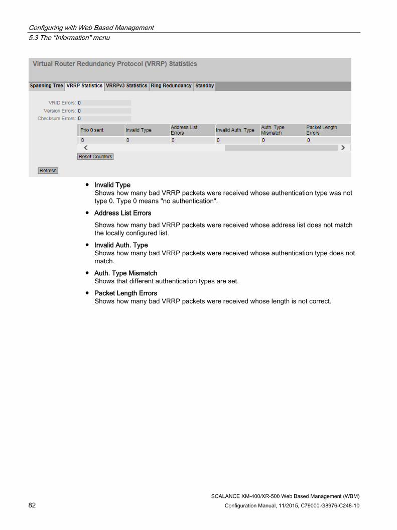
Configuring with Web Based Management 5.3 The "Information" menu
SCALANCE XM-400/XR-500 Web Based Management (WBM) 82 Configuration Manual, 11/2015, C79000-G8976-C248-10
● Invalid Type
Shows how many bad VRRP packets were received whose authentication type was not type 0. Type 0 means "no authentication".
● Address List Errors
Shows how many bad VRRP packets were received whose address list does not match the locally configured list.
● Invalid Auth. Type Shows how many bad VRRP packets were received whose authentication type does not match.
● Auth. Type Mismatch Shows that different authentication types are set.
● Packet Length Errors Shows how many bad VRRP packets were received whose length is not correct.
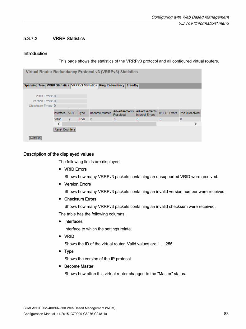
Configuring with Web Based Management 5.3 The "Information" menu
SCALANCE XM-400/XR-500 Web Based Management (WBM) Configuration Manual, 11/2015, C79000-G8976-C248-10 83
5.3.7.3 VRRP Statistics
Introduction This page shows the statistics of the VRRPv3 protocol and all configured virtual routers.
Description of the displayed values The following fields are displayed:
● VRID Errors
Shows how many VRRPv3 packets containing an unsupported VRID were received.
● Version Errors
Shows how many VRRPv3 packets containing an invalid version number were received.
● Checksum Errors
Shows how many VRRPv3 packets containing an invalid checksum were received.
The table has the following columns:
● Interfaces
Interface to which the settings relate.
● VRID
Shows the ID of the virtual router. Valid values are 1 ... 255.
● Type
Shows the version of the IP protocol.
● Become Master
Shows how often this virtual router changed to the "Master" status.

Configuring with Web Based Management 5.3 The "Information" menu
SCALANCE XM-400/XR-500 Web Based Management (WBM) 84 Configuration Manual, 11/2015, C79000-G8976-C248-10
● Advertisements Received
Shows how many VRRPv3 packets were received.
● Advertisement Interval Errors
Shows how many bad VRRPv3 packets were received whose interval does not match the value set locally.
● IP TTL Errors
Shows how many bad VRRPv3 packets were received whose TTL (Time to live) value in the IP header is incorrect.
● Prio 0 received
Shows how many VRRPv3 packets with priority 0 were received. VRRPv3 packets with priority 0 are sent when a master router is shut down. These packets allow a fast handover to the relevant backup router.
● Prio 0 sent
Shows how many VRRPv3 packets with priority 0 were sent. Packets with priority 0 are sent when a master router is shut down. These packets allow a fast handover to the relevant backup router.
● Invalid Type
Shows how many bad VRRPv3 packets were received whose value in the "Type" field of the IP header is invalid.
● Address List Errors
Shows how many bad VRRPv3 packets were received whose address list does not match the locally configured list.
● Packet Length Errors
Shows how many bad VRRPv3 packets were received whose length is not correct.

Configuring with Web Based Management 5.3 The "Information" menu
SCALANCE XM-400/XR-500 Web Based Management (WBM) Configuration Manual, 11/2015, C79000-G8976-C248-10 85
5.3.7.4 Ring redundancy
Information on ring redundancy On this page, you obtain information about the status of the device in terms of ring redundancy. The text boxes on this page are read-only.

Configuring with Web Based Management 5.3 The "Information" menu
SCALANCE XM-400/XR-500 Web Based Management (WBM) 86 Configuration Manual, 11/2015, C79000-G8976-C248-10
Description of the displayed values The table has the following columns:
● Redundancy Function
The "Redundancy Function" column shows the role of the device within the ring:
– No Ring Redundancy (off) The IE switch works without redundancy function.
– HRP Client The IE switch operates as an HRP client.
– HRP Manager The IE switch operates as an HRP manager.
– MRP Client The IE switch operates as an MRP client.
– MRP Manager The IE switch operates as an MRP manager. Using STEP 7, the role "Manager" was set for the device.
– MRP Auto-Manager The IE switch is operating as an MRP manager. Using WBM or CLI the role "MRP Auto-Manager" or using STEP 7 the role "Manager (Auto)" was set.
● RM Status
The "RM Status" column shows whether or not the IE switch is operating as redundancy manager and whether it has opened or closed the ring in this role.
– Passive: The IE switch is operating as redundancy manager and has opened the ring; in other words, the line of switches connected to the ring ports is operating problem free. The passive status is also displayed if the IE switch is not operating as the redundancy manager (RM function disabled).
– Active: The IE switch is operating as redundancy manager and has closed the ring; in other words, the line of switches connected to the ring ports is interrupted (problem). The redundancy manager connects its ring ports through and restores an uninterrupted linear topology.
– If media redundancy in ring topologies is completely disabled, ring ports configured last are displayed and the text "Ring Redundancy disabled" is displayed.
● Observer Status
Shows the current status of the observer.
● Ring Port 1 and Ring Port 2
The "Ring Port 1" and "Ring Port 2" columns show the ports being used as ring ports.
● No. of Changes to RM Active State
Shows how often the device as redundancy manager switched to the active status, i.e. closed the ring.
If the redundancy function is disabled or the device is an "HRP/MRP client" , the text "Redundancy Manager Disabled" appears.

Configuring with Web Based Management 5.3 The "Information" menu
SCALANCE XM-400/XR-500 Web Based Management (WBM) Configuration Manual, 11/2015, C79000-G8976-C248-10 87
● Max. Delay of the RM Test Packets [ms]
Shows the maximum delay time of the test frames of the redundancy manager.
If the redundancy function is disabled or the device is an "HRP/MRP client" , the text "Redundancy Manager Disabled" appears.
● Click the "Reset Counters" button to reset the counters on this page.
5.3.7.5 Standby
Information on standby redundancy On this page, you obtain information about the status of the device in terms of standby redundancy. The text boxes on this page are read-only.
Note Device with the higher MAC address becomes master
When linking HRP rings redundantly, two devices are always configured as a master/slave pair. This also applies to interrupted HRP rings = linear buses. When operating normally, the device with the higher MAC address adopts the role of master.
This type of assignment is important in particular when a device is replaced. Depending on the MAC addresses, the previous device with the slave function can take over the role of the standby master.
The Standby tab shows the status of the standby function:

Configuring with Web Based Management 5.3 The "Information" menu
SCALANCE XM-400/XR-500 Web Based Management (WBM) 88 Configuration Manual, 11/2015, C79000-G8976-C248-10
Description of the displayed values The table has the following columns:
● Standby Ports
Shows the standby port.
● Standby Name
Standby Connection Name
● Standby Function
– Master: The device has a connection to the partner device and is operating as master. In normal operation, the standby port of this device is active.
– Slave: The device has a connection to the partner device and is operating as slave. In normal operation, the standby port of this device is inactive.
– Disabled: Standby link is disabled. The device is operating neither as master nor slave. The port configured as a standby port works as a normal port without standby function.
– Waiting for Connection....: No connection has yet been established to the partner device. The standby port is inactive. In this case, either the configuration on the partner device is inconsistent (for example incorrect connection name, standby link disabled) or there is a physical fault (for example device failure, link down).
– Connection Lost: Existing connection to the partner device has been lost. In this case, either the configuration on the partner device was modified (for example a different connection name, standby link disabled) or there is a physical fault (for example device failure, link down).
● Standby Status
The "Standby Status" display box shows the status of the standby port:
– Active: The standby port of this device is active; in other words is enabled for frame traffic.
– Passive: The standby port of this device is inactive; in other words is blocked for frame traffic.
– "-": The standby function is disabled.
● No. of Changes to Standby Active State
Shows how often the IE switch has changed the standby status from "Passive" to "Active". If the connection of a standby port fails on the standby master, the IE switch changes to the "Active" status.
If the standby function is disabled, the text "Standby Disabled" appears in this box.
Click the "Reset Counters" button to reset the counters on this page.
Following each restart on the device, the counters are automatically reset.

Configuring with Web Based Management 5.3 The "Information" menu
SCALANCE XM-400/XR-500 Web Based Management (WBM) Configuration Manual, 11/2015, C79000-G8976-C248-10 89
5.3.8 Ethernet Statistics
5.3.8.1 Interface Statistics
Interface statistics The page shows the statistics from the interface table of the Management Information Base (MIB).
Description of the displayed values The table has the following columns:
● In Octet
Shows the number of received bytes.
● Out Octet
Shows the number of sent bytes.
● In Unicast
Shows the number of received unicast frames.
● In Non Unicast
Shows the number of received frames that are not of the type unicast.
● Out Unicast
Shows the number of sent unicast frames.

Configuring with Web Based Management 5.3 The "Information" menu
SCALANCE XM-400/XR-500 Web Based Management (WBM) 90 Configuration Manual, 11/2015, C79000-G8976-C248-10
● Out Non Unicast
Shows the number of sent frames that are not of the type unicast.
● In Errors
Shows the number of all possible RX errors, refer to the tab "Packet Error".
5.3.8.2 Packet Size
Frames sorted by length This page displays how many frames of which size were sent and received at each port. You cannot configure anything on this page.
The displayed values are transferred by RMON.
On the page "Layer 2 > RMON > Statistics", you can set the ports for which values will be displayed.

Configuring with Web Based Management 5.3 The "Information" menu
SCALANCE XM-400/XR-500 Web Based Management (WBM) Configuration Manual, 11/2015, C79000-G8976-C248-10 91
Description of the displayed values The table has the following columns:
● Port Shows the available ports and link aggregations. The port is made up of the module number and the port number, for example port 0.1 is module 0, port 1.
Note
Display of frame statistics
In the statistics relating to frame size, note that both incoming and outgoing frames are counted.
● Frame lengths The other columns after the port number contain the absolute numbers of frames according to their frame length. The following frame lengths are distinguished:
– 64 bytes
– 65 - 127 bytes
– 128 - 255 bytes
– 256 - 511 bytes
– 512 - 1023 bytes
– 1024 - max.
Note Data traffic on blocked ports
For technical reasons, data packets can be indicated on blocked ports.
Description of the button "Reset Counters" button
Click "Reset Counters" to reset all counters. The counters are reset by a restart.
5.3.8.3 Frame Type
Received frames sorted by type This page displays how many frames of the type "Unicast", "Multicast" and "Broadcast" were received at each port. You cannot configure anything on this page.
The displayed values are transferred by RMON.
On the page "Layer 2 > RMON > Statistics", you can set the ports for which values will be displayed.

Configuring with Web Based Management 5.3 The "Information" menu
SCALANCE XM-400/XR-500 Web Based Management (WBM) 92 Configuration Manual, 11/2015, C79000-G8976-C248-10
Description of the displayed values The table has the following columns:
● Port Shows the available ports and link aggregations. The port is made up of the module number and the port number, for example port 0.1 is module 0, port 1.
● Unicast / Multicast / Broadcast The other columns after the port number contain the absolute numbers of the incoming frames according to their frame type "Unicast", "Multicast" and "Broadcast".
Description of the button "Reset Counters" button
Click "Reset Counters" to reset all counters. The counters are reset by a restart.
5.3.8.4 Packet Error
Bad received frames This page shows how many bad frames were received per port. You cannot configure anything on this page.
The displayed values are transferred by RMON.
On the page "Layer 2 > RMON > Statistics", you can set the ports for which values will be displayed.

Configuring with Web Based Management 5.3 The "Information" menu
SCALANCE XM-400/XR-500 Web Based Management (WBM) Configuration Manual, 11/2015, C79000-G8976-C248-10 93
Description of the displayed values The table has the following columns:
● Port Shows the available ports and link aggregations. The port is made up of the module number and the port number, for example port 0.1 is module 0, port 1.
● Error types The other columns after the port number contain the absolute numbers of the incoming frames according to their error type.
In the columns of the table, a distinction is made according to the following error types:
– CRC Packets whose content does not match the CRC checksum.
– Undersize Packets with a length less than 64 bytes.
– Oversize Packets discarded because they were too long.
– Fragments Packets with a length less than 64 bytes and a bad CRC checksum.
– Jabbers VLAN-tagged packets with an incorrect CRC checksum that were discarded because they were too long.
– Collisions Collisions that were detected.
Description of the button "Reset Counters" button
Click "Reset Counters" to reset all counters. The counters are reset by a restart.

Configuring with Web Based Management 5.3 The "Information" menu
SCALANCE XM-400/XR-500 Web Based Management (WBM) 94 Configuration Manual, 11/2015, C79000-G8976-C248-10
5.3.8.5 History
Samples of the statistics The page shows samples from each port with information from the RMON statistics.
On the page "Layer 2 > RMON > History", you can set the ports for which samples will be taken.
Figure 5-2 History
Settings ● Port
Select the port for which the history will be displayed.
Description of the displayed values ● Entries
Maximum number of samples that can be saved at the same time.
● Interval [s]
Interval after which the current status of the statistics will be saved as a sample.
The table has the following columns:
● Sample
Number of the sample
● Sample Time
System up time at which the sample was taken.
● Unicast
Number of received unicast frames.

Configuring with Web Based Management 5.3 The "Information" menu
SCALANCE XM-400/XR-500 Web Based Management (WBM) Configuration Manual, 11/2015, C79000-G8976-C248-10 95
● Multicast
Number of received multicast frames.
● Broadcast
Number of received broadcast frames.
● CRC
Number of frames with a bad CRC checksum.
● Undersize
Number of frames that are shorter than 64 bytes.
● Oversize
Number of frames discarded because they were too long.
● Fragments
Number of frames that are shorter than 64 bytes and have a bad CRC checksum.
● Jabbers
Number of frames with a VLAN tag that have a bad CRC checksum and will be discarded because they are too long.
● Collisions
Number of collisions of received frames.
● Utilization [%]
Utilization of the port during a sample.
5.3.9 Unicast
Status of the unicast filter table This page shows the current content of the unicast filter table. This table lists the source addresses of unicast address frames. Entries can be made either dynamically when a node sends a frame to a port or statically by the user setting parameters.

Configuring with Web Based Management 5.3 The "Information" menu
SCALANCE XM-400/XR-500 Web Based Management (WBM) 96 Configuration Manual, 11/2015, C79000-G8976-C248-10
Description of the displayed values This table contains the following columns:
● VLAN ID Shows the VLAN-ID assigned to this MAC address.
● MAC Address Shows the MAC address of the node that the device has learned or the user has configured.
● Status Shows the status of each address entry:
– Learnt The specified address was learned by receiving a frame from this node and will be deleted when the aging time expires if no further packets are received from this node.
Note
If there is a link down, learned MAC entries are deleted.
– Static Configured by the user. Static addresses are stored permanently; in other words, they are not deleted when the aging time expires or when the switch is restarted.
● Port Shows the port via which the node with the specified address can be reached. Frames received by the device whose destination address matches this address will be forwarded to this port.
5.3.10 Multicast
Status of the multicast filter table This table shows the multicast frames currently entered in the multicast filter table and their destination ports. The entries can be dynamic (the device has learned them) or static (the user has set them).
Configuring with Web Based Management 5.3 The "Information" menu
SCALANCE XM-400/XR-500 Web Based Management (WBM) Configuration Manual, 11/2015, C79000-G8976-C248-10 97
Description of the displayed values This table contains the following columns:
● VLAN ID
Shows VLAN ID of the VLAN to which the MAC multicast address is assigned.
● MAC Address
Shows the MAC multicast address that the device has learned or the user has configured.
● Status
Shows the status of each address entry. The following information is possible:
– Static The address was entered statically by the user. Static addresses are stored permanently; in other words, they are not deleted when the aging time expires or when the device is restarted. These must be deleted by the user.
– IGMP The destination port for this address was obtained by IGMP configuration.
– MLD The destination port for this address was determined by MLD configuration.
– GMRP The destination port for this address was registered by a received GMRP frame.
● Port List There is a column for each slot. Within a column, the multicast group to which the port belongs is shown:
– M (Member) Multicast frames are sent via this port.
– R
(Registered) Member of the multicast group, registration was by a GMRP frame.
– I (IGMP/MLD) Member of the multicast group, registration was by an IGMP/MLD frame.
– – Not a member of the multicast group. No multicast frames with the defined multicast MAC address are sent via this port.
– F (Forbidden) Not a member of the multicast group. Moreover, this address may not be an address learned dynamically with GMRP or IGMP/MLD.

Configuring with Web Based Management 5.3 The "Information" menu
SCALANCE XM-400/XR-500 Web Based Management (WBM) 98 Configuration Manual, 11/2015, C79000-G8976-C248-10
5.3.11 LLDP
Status of the neighborhood table This page shows the current content of the neighborhood table. This table stores the information that the LLDP agent has received from connected devices.
You set the interfaces via which the LLDP agent receives or sends information in the following section: "Layer 2 > LLDP".
Figure 5-3 Information LLDP
Description of the displayed values This table contains the following columns:
● System Name
System name of the connected device.
● Device ID
Device ID of the connected device.
● Local Interface
Port at which the IE switch received the information.
● Hold Time
An entry remains stored in the MIB for the time specified here. If the IE switch does not receive any new information from the connected device during this time, the entry is deleted.

Configuring with Web Based Management 5.3 The "Information" menu
SCALANCE XM-400/XR-500 Web Based Management (WBM) Configuration Manual, 11/2015, C79000-G8976-C248-10 99
● Capability
Shows the properties of the connected device:
– Router
– Bridge
– Telephone
– DOCSIS Cable Device
– WLAN Access Point
– Repeater
– Station
– Other
● Port ID
Port of the device with which the IE switch is connected.
5.3.12 Fiber Monitoring Protocol
Monitoring optical links With Fiber Monitoring, you can monitor optical links. The table shows the current status of the ports.
You set the values to be monitored on the following page: "Layer 2 > FMP".
Description of the displayed values Port
Shows the optical ports that support fiber monitoring. This depends on the transceivers.

Configuring with Web Based Management 5.3 The "Information" menu
SCALANCE XM-400/XR-500 Web Based Management (WBM) 100 Configuration Manual, 11/2015, C79000-G8976-C248-10
Rx Power State
● disabled
Fiber monitoring is disabled.
● ok
The value for the received power of the optical link is within the set limits.
● maint. req.
Check the link.
A warning is signaled.
● maint. dem.
The link needs to be checked.
An alarm is signaled and the fault LED is lit.
● link down
The connection to the communications partner is down. No link is detected.
Rx Power [dBm]
Shows the current value of the received power. The value can have a tolerance of +/- 3 dB.
If there is no connection (link down) or fiber monitoring is disabled, "-" is displayed. If fiber monitoring is not enabled on the partner port, the value 0.0 is displayed.
Power Loss State
To be able to monitor the power loss of the connection the function fiber monitoring must be enabled for the optical port of the connection partner.
● disabled
Fiber monitoring is disabled.
● ok
The value for the power loss of the optical link is within the defined limits.
● maint. req.
Check the link.
A warning is signaled.
● maint. dem.
The link needs to be checked.
An alarm is signaled and the fault LED is lit.
● idle
The port has no connection to another port with fiber monitoring enabled.
If no diagnostics information is received from the optical port of the connection partner for 5 cycles, the fiber monitoring connection is assumed to be interrupted. A cycle lasts 5 seconds.
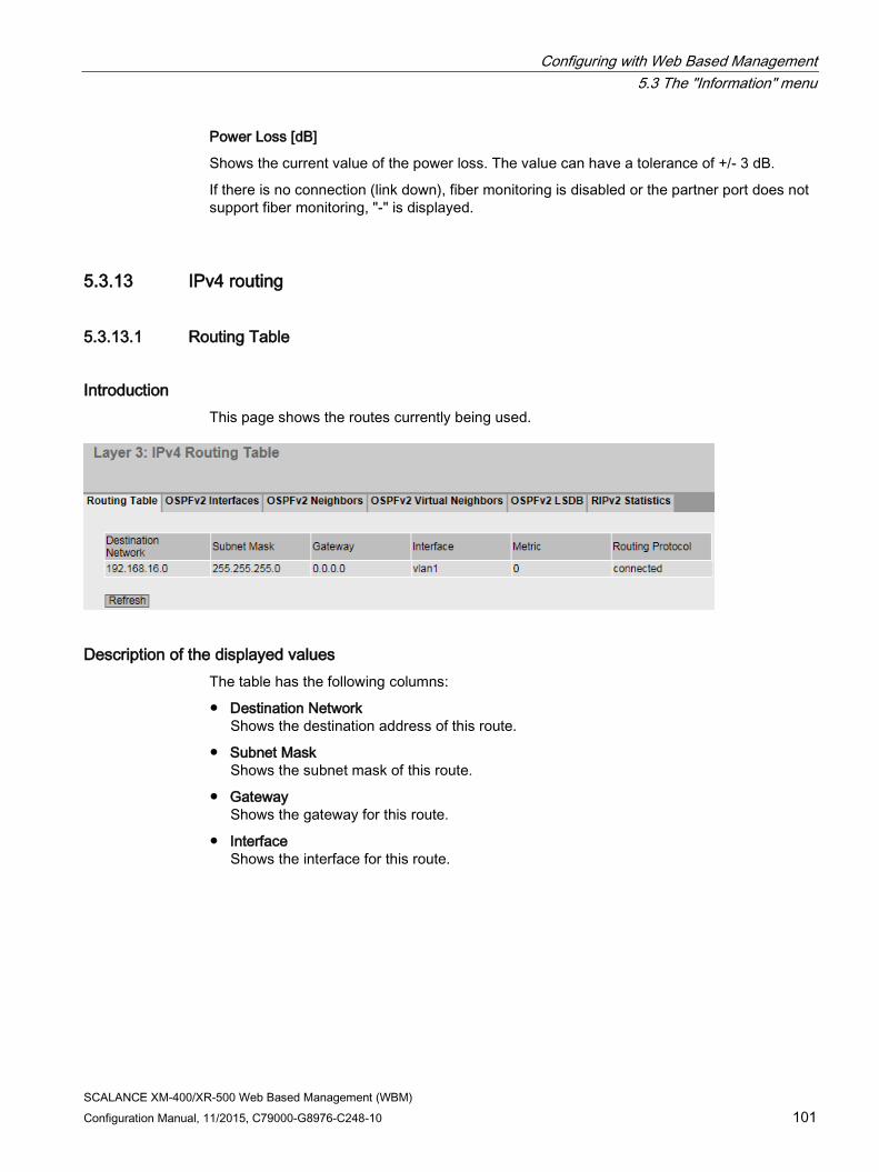
Configuring with Web Based Management 5.3 The "Information" menu
SCALANCE XM-400/XR-500 Web Based Management (WBM) Configuration Manual, 11/2015, C79000-G8976-C248-10 101
Power Loss [dB]
Shows the current value of the power loss. The value can have a tolerance of +/- 3 dB.
If there is no connection (link down), fiber monitoring is disabled or the partner port does not support fiber monitoring, "-" is displayed.
5.3.13 IPv4 routing
5.3.13.1 Routing Table
Introduction This page shows the routes currently being used.
Description of the displayed values The table has the following columns:
● Destination Network Shows the destination address of this route.
● Subnet Mask Shows the subnet mask of this route.
● Gateway Shows the gateway for this route.
● Interface Shows the interface for this route.

Configuring with Web Based Management 5.3 The "Information" menu
SCALANCE XM-400/XR-500 Web Based Management (WBM) 102 Configuration Manual, 11/2015, C79000-G8976-C248-10
● Metric Shows the metric of the route. The higher value, the longer packets require to their destination.
● Routing Protocol Shows the routing protocol from which the entry in the routing table originates. The following entries are possible:
– connected: Connected routes
– Static: Static routes
– RIP: Routes via RIP
– OSPF: Routes via OSPF
– Other: Other routes
5.3.13.2 OSPFv2 Interfaces
Overview This page shows the configuration of the OSPF interface.
Description of the displayed values The table has the following columns:
● IP address Shows the IPv4 address of the OSPF interface
● Area ID Shows the area ID to which the OSPF interface belongs.

Configuring with Web Based Management 5.3 The "Information" menu
SCALANCE XM-400/XR-500 Web Based Management (WBM) Configuration Manual, 11/2015, C79000-G8976-C248-10 103
● Interface Status Shows the status of the WLAN interface:
– Down The interface is not available.
– Loop back Loop back interface
– Waiting Starting up and negotiating the interface.
– Point to Point Point-to-point link
– Designated Router The router is a designated router and generates network LSAs.
– Backup D. Router The router is the backup router for the designated router.
– Other D. Router The Interface has started up. The router is neither a designated nor a designated backup router.
● OSPF Status Shows the status of OSPF.
– Enabled: OSPF is enabled on the interface.
– Disabled: OSPF is disabled on the interface.
● Designated Router Shows the IPv4 address of the designated router for this OSPF interface.
● Backup Designated Router Shows the IPv4 address of the designated backup router for this OSPF interface.
● Events Shows the number of status changes of OSPF.
5.3.13.3 OSPFv2 Neighbors
Overview This page shows the dynamically detected neighbor routers in the relevant networks.
Configuring with Web Based Management 5.3 The "Information" menu
SCALANCE XM-400/XR-500 Web Based Management (WBM) 104 Configuration Manual, 11/2015, C79000-G8976-C248-10
Description of the displayed values The table has the following columns:
● IP Address Shows the IPv4 address of the neighbor router in this network.
● Router ID Shows the ID of the neighbor router. The two addresses can match.
● Status Shows the status of the neighbor router. The status can adopt the following values:
– unknown Status of the neighbor router is unknown.
– down The neighbor router cannot be reached.
– attempt and init Brief status during initialization
– two-way Two-way receipt of Hello packets. Specification of the designated router and the designated backup router.
– exchangestart, exchange and loading Status during exchange of the LSAs
– full The database is complete and synchronized within the area. The routes can now be detected.
Note
Normal status
If the partner router is a designated router or a designated backup router, the status is "full". Otherwise the status is "two-way".
● Assoc. Area Type Shows the area type via which the neighbor-neighbor relation is maintained. The following area types exist:
– Standard
– Stub
– NSSA
– Backbone
● Priority Shows the priority of the neighbor router. This is only significant when selecting the designated router on a network. For virtual neighbor routers, this information is irrelevant.
● Hello suppr Shows the suppressed Hello packets to the neighbor router. This field normally displays "no".

Configuring with Web Based Management 5.3 The "Information" menu
SCALANCE XM-400/XR-500 Web Based Management (WBM) Configuration Manual, 11/2015, C79000-G8976-C248-10 105
● Hello Queue Shows the length of the queue with Hello packets still to be transmitted.
● Events Shows the number of status changes.
5.3.13.4 OSPFv2 Virtual Neighbors
Overview This page shows the configured virtual neighbors.
Description of the displayed values The table has the following columns:
● IP Address Shows the IPv4 address of the virtual neighbor router in this network.
● Router ID Shows the router ID of the virtual neighbor router.

Configuring with Web Based Management 5.3 The "Information" menu
SCALANCE XM-400/XR-500 Web Based Management (WBM) 106 Configuration Manual, 11/2015, C79000-G8976-C248-10
● Status Shows the status of the neighbor router. The status can adopt the following values:
– unknown Status of the neighbor router is unknown.
– down The neighbor router cannot be reached.
– attempt and init Brief status during initialization
– two-way Two-way receipt of Hello packets. Specification of the designated router and the designated backup router.
– exchangestart, exchange and loading Status during exchange of the LSAs
– full The database is complete and synchronized within the area. The routes can now be detected.
Note
Normal status
If the partner router is a designated router or a designated backup router, the status is "full". Otherwise the status is "two-way".
● Trans. Area ID Shows the ID of the area via which the virtual neighborhood relation exists.
● Hello Suppr. Shows whether there are suppressed Hello packets to the virtual neighbor router.
– no: There are no suppressed Hello packets (default)
– yes: There are suppressed Hello packets.
● Hello Queue Shows the length of the queue with Hello packets still to be transmitted.
● Events Shows the number of status changes.

Configuring with Web Based Management 5.3 The "Information" menu
SCALANCE XM-400/XR-500 Web Based Management (WBM) Configuration Manual, 11/2015, C79000-G8976-C248-10 107
5.3.13.5 OSPFv2 LSDB
Overview The link state database is the central database for managing all links within an area. It consists of the link state advertisements (LSAs). The most important data of these LSAs is shown on the this WBM page.

Configuring with Web Based Management 5.3 The "Information" menu
SCALANCE XM-400/XR-500 Web Based Management (WBM) 108 Configuration Manual, 11/2015, C79000-G8976-C248-10
Description of the displayed boxes The table has the following columns:
● Area ID Shows the ID of the area to which the LSA belongs. If the LSA is an external connection, '-' is displayed.
● Link State Type Shows the LSA type. The following values are possible:
– Unknown LSA type is unknown.
– Router The router LSA (Type 1) is sent by the OSPF router within an area. The LSA contains information about the status of all router interfaces.
– Network The network LSA (Type 2) is sent by the designated router within an area. The LSA contains a list of routers connected to the network.
– NSSA External The NSSA external LSA (Type 7) is sent by the NSSA-ASBR within an NSSA. The NSSA-ASBR receives LSAs of Type 5 and converts the information to LSAs of Type 7. The NSSA router can forward these LSAs within an NSSA.
– Summary The summary LSA (Type 3) is sent by the ABR within an area. The LSA contains information about routes to other networks.
– AS Summary The AS summary LSA (Type 4) is sent by the area border router within an area. The LSA contains information about routes to other autonomous systems.
– AS External The AS external LSA (Type 5) is sent by the AS border router within an autonomous system. The LSA contains information about routes from one network to another.
● Link State ID Shows the ID of the LSA.
● Router ID Shows the ID of the router that sent this LSA.
● Sequence Number Shows the sequence number of the LSA. Each time an LSA is renewed, this sequence number is incremented by one.
5.3.13.6 RIPv2 Statistics
Overview This page shows the statistics of the RIP interface.

Configuring with Web Based Management 5.3 The "Information" menu
SCALANCE XM-400/XR-500 Web Based Management (WBM) Configuration Manual, 11/2015, C79000-G8976-C248-10 109
Description of the displayed values
Figure 5-4 RIPv2 Statistics information
The table has the following columns:
● IP Address Shows the IPv4 address of the RIPv2 interface
● Bad packets Number of received RIP packets that were deleted and therefore ignored.
● Bad Routes Number of routes of valid RIP packets that could not be taken into consideration.
● Updates Sent Shows how often the router has sent its routing table to its neighbor routers.
5.3.14 IPv6 routing
5.3.14.1 IPv6 Routing Table
Introduction This page shows the IPv6 routes currently being used.

Configuring with Web Based Management 5.3 The "Information" menu
SCALANCE XM-400/XR-500 Web Based Management (WBM) 110 Configuration Manual, 11/2015, C79000-G8976-C248-10
Description of the displayed values The table has the following columns:
● Destination Network
Shows the destination address of this route.
● Prefix Length
Shows the prefix length of this route.
● Gateway
Shows the gateway for this route.
● Interface
Shows the interface for this route.
● Metric
Shows the metric of the route. The higher value, the longer packets require to their destination.
● Routing Protocol
Shows the routing protocol from which the entry in the routing table originates. The following entries are possible:
– connected: Connected routes
– Static: Static routes
– RIPng: Routes via RIPng
– OSPFv3: Routes via OSPFv3
– other: Other routes
5.3.14.2 OSPFv3 Interfaces
Overview This page shows the configuration of the OSPFv3 interface.

Configuring with Web Based Management 5.3 The "Information" menu
SCALANCE XM-400/XR-500 Web Based Management (WBM) Configuration Manual, 11/2015, C79000-G8976-C248-10 111
Description of the displayed values The table has the following columns:
● Interface
Shows the interface to which the settings relate.
● Area ID
Shows the Area ID to which the OSPF interface belongs.
● Interface Status
Shows the status of the interface.
– Down
The interface is not available.
– Loop back
Loop back interface
– Waiting
Startup and negotiation of the interface.
– Point to Point
Point-to-point connection
– Designated Router
The router is a designated router and generates network LSAs.
– Backup D. Router
The router is the backup router for the designated router.
– S D. Router
The Interface has started up. The router is neither a designated nor a designated backup router.
● OSPF Status
Shows the status of OSPF.
– Enabled: OSPF is enabled on the interface.
– Disabled: OSPF is disabled on the interface.
● Designated Router Shows the IPv6 address of the designated router for this OSPFv3 interface.
● Backup Designated Router Shows the IPv6 address of the designated backup router for this OSPFv3 interface.
● Events Shows the number of status changes of OSPFv3.

Configuring with Web Based Management 5.3 The "Information" menu
SCALANCE XM-400/XR-500 Web Based Management (WBM) 112 Configuration Manual, 11/2015, C79000-G8976-C248-10
5.3.14.3 OSPFv3 Neighbors
Overview This page shows the dynamically detected neighbor routers in the relevant networks.
Description of the displayed values The table has the following columns:
● Interface
Displays the OSPFv3 interface via which the neighbor router can be reached.
● Router ID
Shows the ID of the neighbor router.

Configuring with Web Based Management 5.3 The "Information" menu
SCALANCE XM-400/XR-500 Web Based Management (WBM) Configuration Manual, 11/2015, C79000-G8976-C248-10 113
● Status
Shows the status of the neighbor router. The status can adopt the following values:
– unknown Status of the neighbor router is unknown.
– down The neighbor router cannot be reached.
– attempt und init Short-lived status during initialization
– two-way Two-way receipt of Hello packets. Specification of the designated router and the designated backup router.
– exchangestart, exchange und loading Status during exchange of the LSAs
– full The database is complete and synchronized within the area. The routes can now be detected.
Note
Normal status
If the partner router is a designated router or a designated backup router, the status is "full". Otherwise the status is "two-way".
● Assoc. Area Type
Shows the area type via which the neighbor-neighbor relation is maintained. The following area types exist:
– Standard
– Stub
– NSSA
– Backbone
● Priority
Shows the priority of the neighbor router. This is only significant when selecting the designated router on a network. For virtual neighbor routers, this information is irrelevant.
● Hello suppr
Shows the suppressed Hello packets to the neighbor router. This field normally displays "no".
● Hello Queue
Shows the length of the queue with Hello packets still to be transmitted.
● Events
Shows the number of status changes.

Configuring with Web Based Management 5.3 The "Information" menu
SCALANCE XM-400/XR-500 Web Based Management (WBM) 114 Configuration Manual, 11/2015, C79000-G8976-C248-10
5.3.14.4 OSPFv3 Virtual Neighbors
Overview This page shows the configured virtual neighbors.
Description of the displayed values The table has the following columns:
● Interface
Displays the OSPFv3 interface via which the neighbor router can be reached.
● Router ID
Shows the ID of the virtual neighbor router.

Configuring with Web Based Management 5.3 The "Information" menu
SCALANCE XM-400/XR-500 Web Based Management (WBM) Configuration Manual, 11/2015, C79000-G8976-C248-10 115
● Status
Shows the status of the virtual neighbor router. The status can adopt the following values:
– unknown Status of the neighbor router is unknown.
– down The neighbor router cannot be reached.
– attempt und init Short-lived status during initialization
– two-way Two-way receipt of Hello packets. Specification of the designated router and the designated backup router.
– exchangestart, exchange und loading Status during exchange of the LSAs
– full The database is complete and synchronized within the area. The routes can now be detected.
Note
Normal status
If the partner router is a designated router or a designated backup router, the status is "full". Otherwise the status is "two-way".
● Trans. Area ID Shows the ID of the area via which the virtual neighborhood relation exists.
● Hello suppr
Shows the suppressed Hello packets to the neighbor router. This field normally displays "no".
● Hello Queue
Shows the length of the queue with Hello packets still to be transmitted.
● Events
Shows the number of status changes.

Configuring with Web Based Management 5.3 The "Information" menu
SCALANCE XM-400/XR-500 Web Based Management (WBM) 116 Configuration Manual, 11/2015, C79000-G8976-C248-10
5.3.14.5 OSPFv3 AS-Scope LSDB
Overview The AS-Scope LSDB consists of AS external LSAs. The most important data of these LSAs is shown on this page.
Description of the displayed values The table has the following columns:
● Link State Type
– AS External The AS external LSA (Type 0x4005) is sent by the AS border router within an autonomous system. The LSA contains information about routes from one network to another.
● Link State ID
Shows the ID of the LSA.
● Router ID
Shows the ID of the router that sent this LSA.
● Sequence Number
Shows the sequence number of the LSA. Each time an LSA is renewed, this sequence number is incremented by one.

Configuring with Web Based Management 5.3 The "Information" menu
SCALANCE XM-400/XR-500 Web Based Management (WBM) Configuration Manual, 11/2015, C79000-G8976-C248-10 117
5.3.14.6 OSPFv3 Area-Scope LSDB
Overview The Area-Scope LSDB is the central database for managing all links within an area. The most important data of the LSAs is shown on this page.

Configuring with Web Based Management 5.3 The "Information" menu
SCALANCE XM-400/XR-500 Web Based Management (WBM) 118 Configuration Manual, 11/2015, C79000-G8976-C248-10
Description of the displayed values The table has the following columns:
● Area ID Shows the ID of the area to which the LSA belongs. If the LSA is an external connection, '-' is displayed.
● Link State Type
Shows the LSA type. The following values are possible:
– Router The router LSA (Type 0x2001) is sent by the OSPF router within an area. The LSA contains information about the status of all router interfaces. However, no longer contains address information. This is contained in the new LSA type 0x2009.
– Network The network LSA (Type 0x2002) is sent by the designated router within an area. The LSA contains a list of routers connected to the network. However, no longer contains address information. This is contained in the new LSA type 2009.
– Inter-Area Prefix the inter-area prefix LSA (Type 0x2003) is sent by the ABR within an area. The LSA contains information about routes to other networks.
– Inter-Area Router The inter-area router LSA (Type 0x2004) is sent by the area border router within an area. The LSA contains information about routes to other autonomous systems.
– Type 7 The Type 7 LSA (Type 0x2007) is sent by the NSSA-ASBR within an NSSA. The NSSA-ASBR receives LSAs of Type 0x4005 and converts the information to LSAs of Type 0x2007. The NSSA router can forward these LSAs within an NSSA.
– Intra-Area Prefix The intra-area prefix LSA (Type 0x2009) is only sent within an area. It contains the IPv6 prefixes connected to the router or network.
● Link State ID Shows the ID of the LSA.
● Router ID Shows the ID of the router that sent this LSA.
● Sequence Number Shows the sequence number of the LSA. Each time an LSA is renewed, this sequence number is incremented by one.

Configuring with Web Based Management 5.3 The "Information" menu
SCALANCE XM-400/XR-500 Web Based Management (WBM) Configuration Manual, 11/2015, C79000-G8976-C248-10 119
5.3.14.7 OSPFv3 Link-Scope LSDB
Overview The link scope LSDB consists of the link LSAs. The most important data of these LSAs is shown on this page.
Description of the displayed values The table has the following columns:
● Interface
Shows the OSPFv3 interface to which the link LSA belongs.
● Link State Type
– Link
The link LSA (Type 0x2009) is sent by the router to every router linked to it. It contains the link local address of the router and a list with IPv6 prefixes configured on the link.
● Link State ID
Shows the ID of the LSA.
● Router ID
Shows the ID of the router that sent this LSA.
● Sequence Number
Shows the sequence number of the LSA. Each time an LSA is renewed, this sequence number is incremented by one.

Configuring with Web Based Management 5.3 The "Information" menu
SCALANCE XM-400/XR-500 Web Based Management (WBM) 120 Configuration Manual, 11/2015, C79000-G8976-C248-10
5.3.14.8 RIPng Statistics
Overview This page shows the statistics of the RIPng interfaces.
Figure 5-5 RIPng statistics - Part 1
Description of the displayed values The table has the following columns:
● Interface
Shows the RIPng interface.
● Status
Shows the status of the RIPng interface.
– up
– down
● Messages Received
Shows how often the router has received messages.
● Requests Received
Shows how often the router has received requests.
● Responses Received
Shows how often the router has received responses.
● Unknown Commands
Shows how many RIPng packets were received whose value in the "Commands" field of the RIPng header is unknown. Known values are 1 for requests and 2 for responses.

Configuring with Web Based Management 5.3 The "Information" menu
SCALANCE XM-400/XR-500 Web Based Management (WBM) Configuration Manual, 11/2015, C79000-G8976-C248-10 121
Figure 5-6 RIPng statistics - Part 2
● Other version
Shows how many RIPng packets were received whose value in the "Version" field is not 1.
● Discards
Shows how often the router has discarded RIPng packets.
● Messages Sent
Shows how often the router has sent messages.
● Requests Sent
Shows how often the router has sent requests.
● Responses Sent
Shows how often the router has sent responses.
● Updates Sent
Shows how often the router has sent its routing table to its neighbor routers.
5.3.15 SNMP This page displays the created SNMPv3 groups. You configure the SNMPv3 groups in "System" > SNMP"..

Configuring with Web Based Management 5.3 The "Information" menu
SCALANCE XM-400/XR-500 Web Based Management (WBM) 122 Configuration Manual, 11/2015, C79000-G8976-C248-10
Description The table has the following columns:
● Group Name
Shows the group name.
● User Name
Shows the user that is assigned to the group.
5.3.16 Security
5.3.16.1 Overview
Note
The values displayed depend on the rights of the logged-on user.
This page shows the security settings and the local and external user accounts.

Configuring with Web Based Management 5.3 The "Information" menu
SCALANCE XM-400/XR-500 Web Based Management (WBM) Configuration Manual, 11/2015, C79000-G8976-C248-10 123
Description Services
The "Services" list shows the security settings.
● Telnet Server
You configure the setting in "System > Configuration".
– enabled: Unencrypted access to the CLI.
– disabled: No unencrypted access to the CLI.
● SSH Server
You configure the setting in "System > Configuration".
– enabled: Encrypted access to the CLI.
– disabled: No encrypted access to the CLI.
● Web Server
You configure the setting in "System > Configuration".
– HTTP/HTTPS: Access to the WBM is possible with HTTP and HTTPS.
– HTTPS: Access to the WBM is now only possible with HTTPS.

Configuring with Web Based Management 5.3 The "Information" menu
SCALANCE XM-400/XR-500 Web Based Management (WBM) 124 Configuration Manual, 11/2015, C79000-G8976-C248-10
● SNMP
You can configure setting in "System > SNMP > General".
– "-" (SNMP disabled) Access to device parameters via SNMP is not possible.
– SNMPv1/v2c/v3 Access to device parameters is possible with SNMP versions 1, 2c or 3.
– SNMPv3 Access to device parameters is possible only with SNMP version 3.
● Login Authentication
You configure the setting in "Security > AAA > General".
– Local
The authentication must be made locally on the device.
– RADIUS
The authentication must be handled via a RADIUS server.
– Local and RADIUS
The authentication is possible both with the users that exist on the device (user name and password) and via a RADIUS server.
The user is first searched for in the local database. If the user does not exist there, a RADIUS query is sent.
– RADIUS and fallback local
The authentication must be handled via a RADIUS server.
A local authentication is performed only when the RADIUS server cannot be reached in the network.
Local and external user accounts
You configure local user accounts and roles in "Security > User Accounts"
When you create a local user account an external user account is generated automatically.
Local user accounts involve users each with a password for logging in on the device.
In the table "External User Accounts" a user is linked to a role. In this example the user "Observer" is linked to the "user" role. The user is defined on a RADIUS server. The roll is defined locally on the device. When a RADIUS server authenticates a user, the corresponding group however is unknown or does not exist, the device checks whether or not there is an entry for the user in the table "External User Accounts". If an entry exists, the user is logged in with the rights of the associated role. If the corresponding group is known on the device, both tables are evaluated. The user is assigned the role with the higher rights.
Note
The table "External User Accounts" is only evaluated if you have set "SiemensVSA" in the RADIUS Authorization Mode".
With CLI you can access external user accounts.

Configuring with Web Based Management 5.3 The "Information" menu
SCALANCE XM-400/XR-500 Web Based Management (WBM) Configuration Manual, 11/2015, C79000-G8976-C248-10 125
The table "Local User Accounts" has the following columns:
● User Account
Shows the name of the local user.
● Role
Shows the role of the user. You can obtain more information on the function rights of the role in "Information > Security > Roles".
The table "External User Accounts" has the following columns:
● User Account
Shows the name of the user on the RADIUS server.
● Role
Shows the role assigned to the user on the device. You can obtain more information on this in "Information > Security > Roles".
5.3.16.2 Supported Function Rights
Note
The values displayed depend on the role of the logged-on user.
The page shows the function rights available locally on the device.
Description of the displayed values ● Function Right
Shows the number of the function right. Different rights relating to the device parameters are assigned to the numbers.
● Description
Shows the description of the function right.

Configuring with Web Based Management 5.3 The "Information" menu
SCALANCE XM-400/XR-500 Web Based Management (WBM) 126 Configuration Manual, 11/2015, C79000-G8976-C248-10
5.3.16.3 Roles
Note
The values displayed depend on the role of the logged-on user.
The page shows the roles valid locally on the device.
Description of the displayed values This table contains the following columns:
● Role
Shows the name of the role.
● Function Right
Shows the function right of the role:
– 1
Users with this role can read device parameters but cannot change them.
– 15
Users with this role can both read and change device parameters.
– 0
This is a role that the device assigns internally when a user could not be authenticated. The user is denied access to the device.
● Description
Shows a description of the role.

Configuring with Web Based Management 5.3 The "Information" menu
SCALANCE XM-400/XR-500 Web Based Management (WBM) Configuration Manual, 11/2015, C79000-G8976-C248-10 127
5.3.16.4 Groups
Note
The values displayed depend on the role of the logged-on user.
This page shows which group is linked to which role. The group is defined on a RADIUS server. The roll is defined locally on the device.
Description of the displayed values The table has the following columns:
● Group
Shows the name of the group. The name matches the group on the RADIUS server.
● Role
Shows the name of the role. Users who are authenticated with the linked group on the RADIUS server receive the rights of this role locally on the device.
● Description
Shows a a description for the link.

Configuring with Web Based Management 5.4 The "System" menu
SCALANCE XM-400/XR-500 Web Based Management (WBM) 128 Configuration Manual, 11/2015, C79000-G8976-C248-10
5.4 The "System" menu
5.4.1 Configuration
System configuration The WBM page contains the configuration overview of the access options of the device.
Specify the services that access the device. With some services, there are further configuration pages on which more detailed settings can be made.
Description of the displayed boxes The page contains the following boxes:
● Telnet Server Enable or disable the "Telnet Server" service for unencrypted access to the CLI.
● SSH Server Enable or disable the "SSH Server" service for encrypted access to the CLI.
● HTTPS Server only If this function is enabled, you can only access the device via HTTPS.
● DNS Client
Enable or disable depending on whether the IE switch should operate as a DNS client. You can configure other settings in "System > DNS".
Configuring with Web Based Management 5.4 The "System" menu
SCALANCE XM-400/XR-500 Web Based Management (WBM) Configuration Manual, 11/2015, C79000-G8976-C248-10 129
● SMTP Client Enable or disable the SMTP client. You can configure other settings in "System > SMTP Client".
● Syslog Client Enable or disable the Syslog client. You can configure other settings in "System > Syslog Client".
● DCP Server Specify whether or not the device can be accessed with DCP (Discovery and Configuration Protocol):
– "-" (disabled) DCP is disabled. Device parameters can neither be read nor modified.
– Read/Write With DCP, device parameters can be both read and modified.
– Read Only With DCP, device parameters can be read but cannot be modified.
● Time Setting Select the setting from the drop-down list. The following settings are possible:
– Manual The system time is set manually. You can configure other settings in "System > System Time > Manual Setting".
– SIMATIC Time The system time is set using a SIMATIC time transmitter. You can configure other settings in "System > System Time > SIMATIC Time Client".
– SNTP Client The system time is set via an SNTP server. You can configure other settings in "System > System Time > SNTP Client".
– NTP Client The system time is set via an NTP server. You can configure other settings in "System > System Time > NTP Client".
– PTP Client(SCALANCE XR528-6M and XR552-12M only) The system time is set via a PTP. You can configure other settings in "System > System Time > PTP Client".
● SNMP Select the protocol from the drop-down list. The following settings are possible:
– "-" (SNMP disabled) Access to device parameters via SNMP is not possible.
– SNMPv1/v2c/v3 Access to device parameters is possible with SNMP versions 1, 2c or 3. You can configure other settings in "System > SNMP > General".
– SNMPv3 Access to device parameters is possible only with SNMP version 3. You can configure other settings in "System > SNMP > General".
● SNMPv1/v2 Read-Only Enable or disable write access to SNMP variables with SNMPv1/v2c.

Configuring with Web Based Management 5.4 The "System" menu
SCALANCE XM-400/XR-500 Web Based Management (WBM) 130 Configuration Manual, 11/2015, C79000-G8976-C248-10
● SNMPv1 Traps Enable or disable the sending of traps (alarm frames). You can configure other settings in "System > SNMP > Traps".
● SINEMA configuration interface If the SINEMA configuration interface is enabled, you can download configurations to the IE switch via the TIA Portal.
● NFC(only for SCALANCE XM-400) Activate or deactivate the "NFC" (Near Field Communication) function.
You will find further information on NFC in the "SCALANCE XM400" Operating Instructions.
● Configuration Mode
Select the mode from the drop-down list. The following modes are possible:
– Automatic Save Automatic backup mode. Approximately 1 minute after the last parameter change or when you restart the device, the configuration is automatically saved.
– Trial Trial mode. In Trial mode, although changes are adopted, they are not saved in the configuration file (startup configuration). To save changes in the configuration file, use the "Write startup config" button. The "Write startup config" button is displayed when you set trial mode. The display area also shows the message "Trial Mode Active – Press "Write Startup Config" button to make your settings persistent" as soon as there are unsaved modifications. This message can be seen on every WBM page until the changes made have either been saved or the device has been restarted.
Steps in configuration 1. To use the required function, select the corresponding check box.
2. Select the options you require from the drop-down lists.
3. Click the "Set Values" button.

Configuring with Web Based Management 5.4 The "System" menu
SCALANCE XM-400/XR-500 Web Based Management (WBM) Configuration Manual, 11/2015, C79000-G8976-C248-10 131
5.4.2 General
5.4.2.1 Device
General device information This page contains the general device information.
The boxes "Current System Time", "System Up Time" and "Device Type" cannot be changed.
Description The page contains the following boxes:
● Current System Time Shows the current system time. The system time is either set by the user or by a time-of-day frame: either SINEC H1 time-of-day frame, NTP or SNTP. (readonly)
● System Up Time Shows the operating time of the device since the last restart. (readonly)
● Device Type Shows the type designation of the device. (readonly)
● System Name You can enter the name of the device. The entered name is displayed in the selection area. A maximum of 255 characters are possible. The system name is also displayed in the CLI input prompt. The number of characters in the CLI input prompt is limited. The system name is truncated after 16 characters.

Configuring with Web Based Management 5.4 The "System" menu
SCALANCE XM-400/XR-500 Web Based Management (WBM) 132 Configuration Manual, 11/2015, C79000-G8976-C248-10
● System Contact You can enter the name of a contact person responsible for managing the device. A maximum of 255 characters are possible.
● System Location You can enter the location where the device is installed. The entered installation location is displayed in the selection area. A maximum of 255 characters are possible.
Note
The ASCII code 0x20 to 0x7e is used in the input boxes.
At the start and end of the boxes"System name", "System Contact" and "System Location", the characters "<", ">" and "space" are not permitted.
Procedure 1. Enter the contact person responsible for the device in the "System Contact" input box.
2. Enter the identifier for the location at which the device is installed in the "System Location" input box.
3. Enter the name of the device in the "System Name" input box.
4. Click the "Set Values" button.
5.4.2.2 Coordinates
Information on geographic coordinates In the "Geographic Coordinates" window, you can enter information on the geographic coordinates. The parameters of the geographic coordinates (latitude, longitude and the height above the ellipsoid according to WGS84) are entered directly in the input boxes of the "Geographic Coordinates" window.
Getting the coordinates
Use suitable maps for obtaining the geographic coordinates of the device.
The geographic coordinates can also be obtained using a GPS receiver. The geographic coordinates of these devices are normally displayed directly and only need to be entered in the input boxes of this page.

Configuring with Web Based Management 5.4 The "System" menu
SCALANCE XM-400/XR-500 Web Based Management (WBM) Configuration Manual, 11/2015, C79000-G8976-C248-10 133
Description The page contains the following boxes. These are purely information boxes with a maximum length of 32 characters.
● "Latitude" input box Geographical latitude: Here, enter the value for the northerly or southerly latitude of the location of the device.
For example, the value +49° 1´31.67" means that the device is located at 49 degrees, 1 arc minute and 31.67 arc seconds northerly latitude. A southerly latitude is shown by a preceding minus character. You can also append the letters N (northerly latitude) or S (southerly latitude) to the numeric information (49° 1´31.67" N).
● "Longitude" input box Geographic longitude: Here, you enter the value of the eastern or western longitude of the location of the device. The value +8° 20´58.73" means that the device is located at 8 degrees, 20 minutes and 58.73 seconds east. A western longitude is indicated by a preceding minus sign. You can also add the letter E (easterly longitude) or W (westerly longitude) to the numeric information (8° 20´58.73" E).
● Input box: "Height" Height Here, you enter the value of the geographic height above sea level in meters. For example, 158 m means that the device is located at a height of 158 m above sea level. Heights below sea level (for example the Dead Sea) are indicated by a preceding minus sign.
Procedure 1. Enter the calculated latitude in the "Latitude" input box.
2. Enter the calculated longitude in the "Longitude" input box.
3. Enter the height above sea level in the "Height" input box.
4. Click the "Set Values" button.
5.4.3 Agent IP Here, you specify the IP configuration for the device.
With devices with more than one IP interface, this call references the "Subnets > Configuration" menu item in the "Layer 3" menu and the configuration of the TIA interface there.

Configuring with Web Based Management 5.4 The "System" menu
SCALANCE XM-400/XR-500 Web Based Management (WBM) 134 Configuration Manual, 11/2015, C79000-G8976-C248-10
5.4.4 DNS On this page, you can configure up to 3 DNS servers. If there is more than one server, the order in the table specifies the order in which the servers are queried. The top server is queried first.
The DNS () server (Domain Name System) assigns a domain name to an IP address so that a device can be uniquely identified.
If this function is enabled, the IE switch can communicate with a DNS server as a DNS client. You have the option of entering names in IP address boxes.
Note
The DNS client function can only be used if there is a DNS server in the network.
Description
Figure 5-7 DNS client

Configuring with Web Based Management 5.4 The "System" menu
SCALANCE XM-400/XR-500 Web Based Management (WBM) Configuration Manual, 11/2015, C79000-G8976-C248-10 135
The page contains the following boxes:
● DNS Client
Enable or disable depending on whether the IE switch should operate as a DNS client.
● Used DNS Servers
Here you specify which DNS server the device uses:
– learned only
The device uses only the DNS servers assigned by DHCP.
– manual only
The device uses only the manually configured DNS servers. The DNS servers must be connected to the Internet. A maximum of three DNS servers can be configured.
– all
The device uses all available DNS servers.
● DNS Server Address
Enter the IP address of the DNS server.
This table contains the following columns:
● Select
Select the check box in the row to be deleted.
● DNS Server Address
Shows the IP address of the DNS server.
● Origin
This shows whether the DNS server was configured manually or was assigned by DHCP.
Procedure Activating DNS
1. Enable the "DNS-Client" check box.
2. Click the "Set Values" button.
Creating a DNS server
1. In the "DNS Server Address" box, enter the IP address of the DNS server.
2. Click the "Create" button.
Filtering DNS servers
1. In the "Used DNS Servers" drop-down list, select which DNS servers are to be used.
2. Click the "Set Values" button.
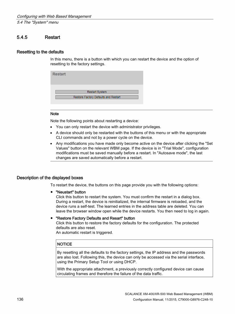
Configuring with Web Based Management 5.4 The "System" menu
SCALANCE XM-400/XR-500 Web Based Management (WBM) 136 Configuration Manual, 11/2015, C79000-G8976-C248-10
5.4.5 Restart
Resetting to the defaults In this menu, there is a button with which you can restart the device and the option of resetting to the factory settings.
Note
Note the following points about restarting a device: • You can only restart the device with administrator privileges. • A device should only be restarted with the buttons of this menu or with the appropriate
CLI commands and not by a power cycle on the device. • Any modifications you have made only become active on the device after clicking the "Set
Values" button on the relevant WBM page. If the device is in "Trial Mode", configuration modifications must be saved manually before a restart. In "Autosave mode", the last changes are saved automatically before a restart.
Description of the displayed boxes To restart the device, the buttons on this page provide you with the following options:
● "Neustart" button Click this button to restart the system. You must confirm the restart in a dialog box. During a restart, the device is reinitialized, the internal firmware is reloaded, and the device runs a self-test. The learned entries in the address table are deleted. You can leave the browser window open while the device restarts. You then need to log in again.
● "Restore Factory Defaults and Resart" button Click this button to restore the factory defaults for the configuration. The protected defaults are also reset. An automatic restart is triggered.
NOTICE
By resetting all the defaults to the factory settings, the IP address and the passwords are also lost. Following this, the device can only be accessed via the serial interface, using the Primary Setup Tool or using DHCP.
With the appropriate attachment, a previously correctly configured device can cause circulating frames and therefore the failure of the data traffic.

Configuring with Web Based Management 5.4 The "System" menu
SCALANCE XM-400/XR-500 Web Based Management (WBM) Configuration Manual, 11/2015, C79000-G8976-C248-10 137
5.4.6 Load & Save
Overview of the file types File type Description Config Start configuration ConfigPack Detailed configuration information. for example, start configuration, users,
certificates Debug This file contains information for Siemens Support. Firmware Firmware GSDML Information on the device properties HTTPSCert HTTPS certificate LogFile File with entries from the event log table MIB Private MSPS MIB file "Scalance_w_msps.mib" RunningCLI This file contains an overview of the current configuration in the form of CLI
commands. You can download the text file. The file is not intended to be up-loaded again unchanged.
Script CLI script file StartupInfo Startup log file Users File with user names and passwords
5.4.6.1 HTTP
Loading and saving data via HTTP The WBM allows you to store device data in an external file on your client PC or to load such data from an external file from the client PC to the devices. This means, for example, that you can also load new firmware from a file located on your client PC.
Note
This WBM page is available both for connections using HTTP and for connections using HTTPS.

Configuring with Web Based Management 5.4 The "System" menu
SCALANCE XM-400/XR-500 Web Based Management (WBM) 138 Configuration Manual, 11/2015, C79000-G8976-C248-10
Firmware
The firmware is signed and encrypted. This ensures that only firmware created by Siemens can be downloaded to the device.
Note Incompatibility with previous firmware versions with/without PLUG inserted
During the installation of a previous version, the configuration data can be lost. In this case, the device starts up with the factory settings after the firmware has been installed.
In this situation, if a PLUG is inserted in the device, following the restart, this has the status "Not Accepted" since the PLUG still has the configuration data of the previous more up-to-date firmware. This allows you to return to the previous, more up-to-date firmware without any loss of configuration data. If the original configuration on the PLUG is no longer required, the PLUG can be deleted or rewritten manually using the WBM page "System > PLUG".
Configuration files
Note Configuration files and trial mode/Automatic Save mode
In Automatic Save mode, the data is saved automatically before the configuration files (ConfigPack and Config) are transferred. In Trial mode, although the changes are adopted, they are not saved in the configuration files (ConfigPack and Config). Use the "Write Startup Config" button on the "System > Configuration" WBM page to save changes in the configuration files.
CLI script file
You can download existing CLI configurations (RunningCLI) and upload your own CLI scripts (Script).
Note
The downloadable CLI script is not intended to be uploaded again unchanged.

Configuring with Web Based Management 5.4 The "System" menu
SCALANCE XM-400/XR-500 Web Based Management (WBM) Configuration Manual, 11/2015, C79000-G8976-C248-10 139
Description of the displayed boxes The table has the following columns:
● Type Shows the file type.
● Description Shows the short description of the file type.
● Load With this button, you can upload files to the device. The button can be enabled, if this function is supported by the file type.
● Save With this button, you can download files from the device. The button can only be enabled if this function is supported by the file type and the file exists on the device.
● Delete With this button, you can delete files from the device. The button can only be enabled if this function is supported by the file type and the file exists on the device.
Note
Following a firmware update, delete the cache of your Internet browser.

Configuring with Web Based Management 5.4 The "System" menu
SCALANCE XM-400/XR-500 Web Based Management (WBM) 140 Configuration Manual, 11/2015, C79000-G8976-C248-10
Steps in configuration
Uploading files using HTTP
1. Start the upload function by clicking the one of the "Load" buttons.
A dialog for uploading a file opens.
2. Select the required file and confirm the upload.
The file is uploaded.
3. If a restart is necessary, a message to this effect will be output. Click the "OK" button and a restart will follow. If you click the "Abort" button, there is no device restart. The changes only take effect after a restart.
Downloading files using HTTP
1. Start the download by clicking the one of the "Save" buttons.
2. Select a storage location and a name for the file.
3. Save the file.
The file is downloaded and saved.
Deleting files using HTTP
1. Start the delete function by clicking the one of the "Delete" buttons.
The file is deleted.
Reusing configuration data
If several devices are to receive the same configuration and the IP addresses are assigned using DHCP, the effort for configuration can be reduced by saving and reading in the configuration data.
Follow the steps below to reuse configuration data:
1. Save the configuration data of a configured device on your PC.
2. Load this configuration file on all other devices you want to configure in this way.
3. If individual settings are necessary for specific devices, these must be made online on the relevant device.
Note
Configuration data has a checksum. If you edit the files, you can no longer upload them to the IE switch.
Configuring with Web Based Management 5.4 The "System" menu
SCALANCE XM-400/XR-500 Web Based Management (WBM) Configuration Manual, 11/2015, C79000-G8976-C248-10 141
5.4.6.2 TFTP
Loading and saving data via a TFTP server On this page, you can configure the TFTP server and the file names. The WBM also allows you to store device data in an external file on a TFTP server or to load such data from an external file from the TFTP server to the devices. This means, for example, that you can also load new firmware from a file located on a TFTP server.
Firmware
The firmware is signed and encrypted. This ensures that only firmware created by Siemens can be downloaded to the device.
Note Incompatibility with previous firmware versions with/without PLUG inserted
During the installation of a previous version, the configuration data can be lost. In this case, the device starts up with the factory settings after the firmware has been installed.
In this situation, if a PLUG is inserted in the device, following the restart, this has the status "Not Accepted" since the PLUG still has the configuration data of the previous more up-to-date firmware. This allows you to return to the previous, more up-to-date firmware without any loss of configuration data. If the original configuration on the PLUG is no longer required, the PLUG can be deleted or rewritten manually using the WBM page "System > PLUG".
Configuration files
Note Configuration files and trial mode/Automatic Save mode
In Automatic Save mode, the data is saved automatically before the configuration files (ConfigPack and Config) are transferred. In Trial mode, although the changes are adopted, they are not saved in the configuration files (ConfigPack and Config). Use the "Write Startup Config" button on the "System > Configuration" WBM page to save changes in the configuration files.
CLI script file
You can download existing CLI configurations (RunningCLI) and upload your own CLI scripts (Script).
Note
The downloadable CLI script is not intended to be uploaded again unchanged.
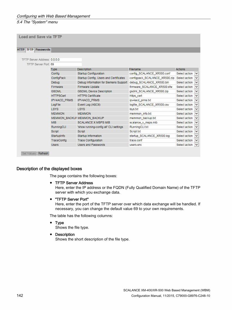
Configuring with Web Based Management 5.4 The "System" menu
SCALANCE XM-400/XR-500 Web Based Management (WBM) 142 Configuration Manual, 11/2015, C79000-G8976-C248-10
Description of the displayed boxes The page contains the following boxes:
● TFTP Server Address Here, enter the IP address or the FQDN (Fully Qualified Domain Name) of the TFTP server with which you exchange data.
● "TFTP Server Port" Here, enter the port of the TFTP server over which data exchange will be handled. If necessary, you can change the default value 69 to your own requirements.
The table has the following columns:
● Type Shows the file type.
● Description Shows the short description of the file type.

Configuring with Web Based Management 5.4 The "System" menu
SCALANCE XM-400/XR-500 Web Based Management (WBM) Configuration Manual, 11/2015, C79000-G8976-C248-10 143
● Filename A file name is preset here for every file type.
Note
Changing the file name
You can change the file name preset in this column. After clicking the "Set Values" button, the changed name is saved on the device and can also be used with the Command Line Interface.
● Actions Select the action from the drop-down list. The selection depends on the selected file type, for example you can only save the log file. The following actions are possible:
– Save file With this selection, you save a file on the TFTP server.
– Load file With this selection, you load a file from the TFTP server.
Steps in configuration Loading or saving data using TFTP
1. Enter the IP address or the FQDN of the TFTP server in the "TFTP Server Address" input box.
2. Enter the server port of the TFTP server to be used in the in the "TFTP Server Port" input box.
3. If applicable, enter the name of a file in which you want to save the data or take the data from in the "File name" input box.
4. Select the action you want to execute from the "Actions" drop-down list.
5. Click the "Set Values" button to start the selected actions.
6. If a restart is necessary, a message to this effect will be output. Click the "OK" button and a restart will follow. If you click the "Abort" button, there is no device restart. The changes only take effect after a restart.
Reusing configuration data
If several devices are to receive the same configuration and the IP addresses are assigned using DHCP, the effort for configuration can be reduced by saving and reading in the configuration data.
Follow the steps below to reuse configuration data:
1. Save the configuration data of a configured device on your PC.
2. Load this configuration file on all other devices you want to configure in this way.
3. If individual settings are necessary for specific devices, these must be made online on the relevant device.
Note that the configuration data is coded when it is saved. This means that you cannot edit the files with a text editor.

Configuring with Web Based Management 5.4 The "System" menu
SCALANCE XM-400/XR-500 Web Based Management (WBM) 144 Configuration Manual, 11/2015, C79000-G8976-C248-10
5.4.6.3 Passwords There are files to which access is password protected. To load the file on the device, enter the password specified for the file on the WBM page.
Description The table has the following columns:
● Type Shows the file type.
● Description Shows the short description of the file type.
● Enabled When selected, the password is used. Can only be enabled if the password is configured.
● Password Enter the password for the file.
● Password Confirmation Confirm the password.
● Status Shows whether the current settings for the file match the device.
– Valid the "Enabled" check box is selected and the password matches the certificate.
– Invaalid the "Enabled" check box is selected but the password does not match the certificate or no certificate has been loaded yet.
– '-' The password cannot be evaluated or is not yet being used. The "Enabled" check box is not selected.
Procedure 1. Enter the password in "Password".
2. To confirm the password, enter the password again in "Password Confirmation".
3. Select the "Enabled" option.
4. Click the "Set Values" button.

Configuring with Web Based Management 5.4 The "System" menu
SCALANCE XM-400/XR-500 Web Based Management (WBM) Configuration Manual, 11/2015, C79000-G8976-C248-10 145
5.4.7 Events
5.4.7.1 Configuration
Selecting system events On this page, you specify how a device reacts to system events. By enabling the appropriate options, you specify how the device reacts to events. To enable or disable the options, click the relevant check boxes of the columns.

Configuring with Web Based Management 5.4 The "System" menu
SCALANCE XM-400/XR-500 Web Based Management (WBM) 146 Configuration Manual, 11/2015, C79000-G8976-C248-10
Description of the displayed boxes The page contains the following boxes:
● "Signaling Contact Method" drop-down list Select the reaction of the signaling contact from the drop-down list. The following reactions are possible:
– conventional Default setting for the signaling contact. An error/fault is displayed by the fault LED and the signaling contact is opened. When the error/fault state no longer exists, the fault LED goes off and the signaling contact is closed.
– User Defined The way the signaling contact works does not depend on the error/fault that has occurred. The signaling contact can be opened or closed as required by user actions.
● ""Signaling Contact Status" drop-down list Select the status of the signaling contact from the drop-down list. The following states are possible:
– Closed Signaling contact is closed.
– Open Signaling contact is opened.
The table has the following columns:
● E-Mail The device sends an e-mail. This is only possible if the SMTP server is set up and the "SMTP client" function is enabled.
● Trap The device sends an SNMP trap. This is only possible if "SNMPv1 Traps" is enabled in "System > Configuration".
● Log table The device writes an entry in the event log table, see "Information > Log Table"
● Syslog The device writes an entry to the system log server. This is only possible if the system log server is set up and the "Syslog client" function is enabled.

Configuring with Web Based Management 5.4 The "System" menu
SCALANCE XM-400/XR-500 Web Based Management (WBM) Configuration Manual, 11/2015, C79000-G8976-C248-10 147
● Faults The device triggers an error. The error LED lights up
● Event The column contains the following values:
– Cold/Warm Start The device was turned on or restarted by the user.
– Link Change This event occurs only when the port status is monitored and has changed, see "System > Fault Monitoring > Link Change".
– Authentication Failure This event occurs when access is attempted with an incorrect password.
– RMON Alarm An alarm or event has occurred relating to the remote monitoring of the system.
– Power Change This event occurs only when power supply lines 1 and 2 are monitored. It indicates that there was a change to line 1 or line 2. See "System > Fault Monitoring > Power Supply".
– RM State Change The redundancy manager has recognized an interruption or restoration of the ring and has switched the line over or back.
– Spanning Tree Change The STP or RSTP or MSTP topology has changed.
– Fault State Change The fault status has changed. The fault status can relate to the activated port monitoring, the response of the signaling contact or the power supply monitoring.
– Standby State Change A device with an established standby connection (master or slave) has activated or deactivated the link to the other ring (standby port). The data traffic was redirected from one Ethernet connection (standby port of the master) to another Ethernet connection (standby port of the slave).
– VRRP State Change (only when routing via VRRP) The status of the virtual router has changed
– Loop Detection
A loop was detected in the network segment.
– OSPF State Change
The status of OSPF has changed.
– Pnac Port Authentication State Change This event occurs with 802.1X authentications.
– PoE State Change The status of PoE has changed.
– FMP Status Change The value of the received power or the power loss has exceeded or fallen below a certain limit.

Configuring with Web Based Management 5.4 The "System" menu
SCALANCE XM-400/XR-500 Web Based Management (WBM) 148 Configuration Manual, 11/2015, C79000-G8976-C248-10
Steps in configuration 1. Select the check box in the row of the required event. Select the event in the column
under the following actions:
– Trap
– Log Table
– Syslog
– Faults
2. Click the "Set Values" button.
5.4.7.2 Severity Filters
Setting the Severity Filters On this page, set the threshold levels for sending system event notifications.
The first table column shows the client type for which you are making the settings:
Sending system event messages by e-mail
● Log Table
Entry of system events in the log table
● Syslog
Entry of system events in the Syslog file
Select the required level from the drop-down lists of the second table column.

Configuring with Web Based Management 5.4 The "System" menu
SCALANCE XM-400/XR-500 Web Based Management (WBM) Configuration Manual, 11/2015, C79000-G8976-C248-10 149
You can select from the following values:
● Critical System events are processed as of the severity level "Critical".
● Warning
System events are processed as of the severity level "Warning".
● Info System events are processed as of the severity level "Info".
Procedure Follow the steps below to configure the required level:
1. Select the required values from the drop-down lists of the second table column after the client types.
2. Click the "Set Values" button.
5.4.8 SMTP client
Network monitoring with e-mails The device provides the option of automatically sending an e-mail if an alarm event occurs (for example to the network administrator). The e-mail contains the identification of the sending device, a description of the cause of the alarm in plain language, and a time stamp. This allows centralized network monitoring to be set up for networks with few nodes based on an e-mail system. When an e-mail error message is received, the WBM can be started by the Internet browser using the identification of the sender to read out further diagnostics information.
On this page, you can configure up to three SMTP servers and the corresponding e-mail addresses.

Configuring with Web Based Management 5.4 The "System" menu
SCALANCE XM-400/XR-500 Web Based Management (WBM) 150 Configuration Manual, 11/2015, C79000-G8976-C248-10
Description The page contains the following boxes:
● SMTP Client Enable or disable the SMTP client.
● Sender Email Address Enter the name of the sender to be included in the e-mail, for example the device name.
This setting applies to all configured SMTP servers.
● Send Test Mail
Send a test e-mail to check your configuration.
● SMTP Port
Enter the port via which your SMTP server can be reached.
Factory settings: 25
This setting applies to all configured SMTP servers.
● SMTP Server Address Enter the IP address or the FQDN (Fully Qualified Domain Name) of the SMTP server.
This table contains the following columns:
● Select Select the check box in a row to be deleted.
● SMTP Server Address Shows the IP address or the FQDN (Fully Qualified Domain Name) of the SMTP server.
● Receiver Email Address Enter the e-mail address to which the device sends an e-mail if a fault occurs.
Procedure 1. Enable the "SMTP Client" option.
2. Enter the IP address of the SMTP server or the FQDN in the "SMTP Server Address" input box.
3. Click the "Create" button. A new entry is generated in the table.
4. In the Receiver Email Address input box. enter the e-mail address to which the device sends an e-mail if a fault occurs.
5. Click the "Set Values" button.
Note
Depending on the properties and configuration of the SMTP server, it may be necessary to adapt the "Sender E-Mail Address” input box for the e-mails. Check with the administrator of the SMTP server.

Configuring with Web Based Management 5.4 The "System" menu
SCALANCE XM-400/XR-500 Web Based Management (WBM) Configuration Manual, 11/2015, C79000-G8976-C248-10 151
5.4.9 DHCP client
Setting the DHCP mode If the DHCP mode is activated, the DHCP client starts a DHCP request to a configured DHCP server and is assigned an IPv4 address as the response. The server manages an address range from which it assigns IPv4 addresses. It is also possible to configure the server so that the client always receives the same IPv4 address in response to its request.
Description The page contains the following boxes:
● "DHCP client configuration request (opt. 66, 67)" Enable this option if you want the DHCP client to use options 66 and 67 to download and then enable a configuration file.
● DHCP Mode Select the DHCP mode from the drop-down list. The following modes are possible:
– via MAC Address Identification is based on the MAC address.
– via DHCP Client ID Identification is based on a freely defined DHCP client ID.
– Via System Name Identification is based on the system name. If the system name is 255 characters long, the last character is not used for identification.
– via PNIO Name of Station identification is based on the PNIO name of the station.
The table has the following columns:
● Interface Interface to which the setting relates.
● DHCP Enable or disable the DHCP client for the relevant interface.

Configuring with Web Based Management 5.4 The "System" menu
SCALANCE XM-400/XR-500 Web Based Management (WBM) 152 Configuration Manual, 11/2015, C79000-G8976-C248-10
Procedure Follow the steps below to configure the IP address using the DHCP client ID:
1. Enable the "DHCP Client" option.
2. Select the "via DHCP client ID" DHCP mode from the "DHCP Mode" drop-down list.
3. Enter a character string to identify the device in the enabled "DHCP Client ID" input box. This is then evaluated by the DHCP server.
4. Select the "DHCP Client Configuration Request (Opt.66, 67)" option, if you want the DHCP client to use options 66 and 67 to download and then enable a configuration file.
5. Click the "Set Values" button.
Note
If a configuration file is downloaded, this can trigger a system restart. If the currently running configuration and the configuration in the downloaded configuration file differ, the system is restarted.
Make sure that the option "DHCP Client Configuration Request (Opt.66, 67)" is no longer set in this configuration file.
5.4.10 SNMP
5.4.10.1 General
Configuration of SNMP On this page, you make the basic settings for SNMP. Enable the check boxes according to the function you want to use.

Configuring with Web Based Management 5.4 The "System" menu
SCALANCE XM-400/XR-500 Web Based Management (WBM) Configuration Manual, 11/2015, C79000-G8976-C248-10 153
Description The page contains the following boxes:
● SNMP Select the SNMP protocol from the drop-down list. The following settings are possible:
– "-" (disabled) SNMP is disabled.
– SNMPv1/v2c/v3 SNMPv1/v2c/v3 is supported.
– SNMPv3 Only SNMPv3 is supported.
● SNMPv1/v2c Read-Only If you enable this option, SNMPv1/v2c can only read the SNMP variables.
Note
Community String
For security reasons, do not use the standard values "public" or "private". Change the community strings following the initial installation.
● SNMPv1/v2c Read Community String Enter the community string for read access of the SNMP protocol.
● SNMPv1/v2c Read/Write Community String Enter the community string for read and write access of the SNMP protocol.
● SNMPv1 Traps Enable or disable the sending of SNMP traps (alarm frames). On the "Trap" tab, specify the IP addresses of the devices to which SNMP traps will be sent.
● SNMPv1/v2c Trap Community String Enter the community string for sending SNMPv1/v2 messages.
Procedure 1. Select the required option from the "SNMP" drop-down list:
– "-" (disabled)
– SNMPv1/v2c/v3
– SNMPv3
2. Enable the "SNMPv1/v2c schreibgeschützt" check box if you only want read access to SNMP variables with SNMPv1/v2c.
3. Enter the required character string in the "SNMPv1/v2c Read Community String" input box.
4. Enter the required character string in the "SNMPv1/v2c Read/Write Community String" input box.
5. Click the "Set Values" button.

Configuring with Web Based Management 5.4 The "System" menu
SCALANCE XM-400/XR-500 Web Based Management (WBM) 154 Configuration Manual, 11/2015, C79000-G8976-C248-10
5.4.10.2 Traps
SNMP traps for alarm events If an alarm event occurs, a device can send SNMP traps (alarm frames) to up to ten different management stations at the same time. Traps are only sent if the events specified in the "Events" menu occur.
Note
Traps are only sent if you have enabled the option "SNMPv1 Traps" in the "General" tab or in "System > Configuration".
Description ● Trap Receiver Address
Enter the IP address or the FQDN name of the station to which the device sends SNMP traps. You can specify up to ten different recipients servers.
The table has the following columns:
● Select Select the row you want to delete.
● Trap Receiver Address If necessary, change the IP addresses or the FQDN names of the stations.
● Trap Enable or disable the sending of traps. Stations that are entered but not selected do not receive SNMP traps.
Procedure Creating a trap entry
1. In "Trap Receiver Address", enter the IP address or the FQDN name of the station to which the device sends traps.
2. Click the "Create" button to create a new trap entry.

Configuring with Web Based Management 5.4 The "System" menu
SCALANCE XM-400/XR-500 Web Based Management (WBM) Configuration Manual, 11/2015, C79000-G8976-C248-10 155
3. Select the check box in the required row "Trap".
4. Click the "Set Values" button.
Deleting a trap entry
1. Enable "Select" in the row to be deleted.
2. Click the "Delete" button. The entry is deleted.
5.4.10.3 v3 Groups
Security settings and assigning permissions SNMP version 3 allows permissions to be assigned, authentication, and encryption at protocol level. The security levels and read/write permissions are assigned according to groups. The settings automatically apply to every member of a group.
Description The page contains the following boxes:
● Group Name Enter the name of the group. The maximum length is 32 characters.
● Security Level Select the security level (authentication, encryption) valid for
the selected group. In the security levels, the following options:
– no Auth/no Priv No authentication enabled / no encryption enabled.
– Auth/no Priv Authentication enabled / no encryption enabled.
– Auth/Priv Authentication enabled / encryption enabled.

Configuring with Web Based Management 5.4 The "System" menu
SCALANCE XM-400/XR-500 Web Based Management (WBM) 156 Configuration Manual, 11/2015, C79000-G8976-C248-10
The table has the following columns:
● Select Select the row you want to delete.
● Group Name Shows the defined group names.
● Security Level Shows the configured security level.
● Read Enable or disable read access for the required group.
● Write Enable or disable write access for the required group.
Note
For write access to work, you also need to enable read access.
● Persistence Shows whether or not the group is assigned to an SNMPv3 user. If the group is not assigned to an SNMPv3 user, no automatic saving is triggered and the configured group disappears again after restarting the device.
– Yes
The group is assigned to an SNMPV3 user.
– No
The group is not assigned to an SNMPV3 user.
Procedure Creating a new group
1. Enter the required group name in "Group Name".
2. Select the required security level from the "Security Level" drop-down list.
3. Click the "Create" button to create a new entry.
4. Specify the required read rights for the group in " Read".
5. Specify the required write rights for the group in " Write".
6. Click the "Set Values" button.

Configuring with Web Based Management 5.4 The "System" menu
SCALANCE XM-400/XR-500 Web Based Management (WBM) Configuration Manual, 11/2015, C79000-G8976-C248-10 157
Modifying a group
1. Specify the required read rights for the group in " Read".
2. Specify the required write rights for the group in " Write".
3. Click the "Set Values" button.
Note
Once a group name and the security level have been specified, they can no longer be modified after the group is created. If you want to change the group name or the security level , you will need to delete the group and recreate it and reconfigure it with the new name.
Deleting a group
1. Enable "Select" in the row to be deleted. Repeat this for all groups you want to delete.
2. Click the "Delete" button. The entries are deleted.
5.4.10.4 v3 users
User-specific security settings On the WBM page, you can create new SNMPv3 users and modify or delete existing users. The user-based security model works with the concept of the user name; in other words, a user ID is added to every frame. This user name and the applicable security settings are checked by both the sender and recipient.
Description The page contains the following boxes:
● User Name Enter a freely selectable user name. After you have entered the data, you can no longer modify the name.

Configuring with Web Based Management 5.4 The "System" menu
SCALANCE XM-400/XR-500 Web Based Management (WBM) 158 Configuration Manual, 11/2015, C79000-G8976-C248-10
The table has the following columns:
● Select Select the row you want to delete.
● User Name Shows the created users.
● Group Name Select the group which will be assigned to the user.
● Authentication Protocol Specify the authentication protocol. Can only be enabled, if this group supports the function.
The following settings are available:
– None
– MD5
– SHA
● Privacy Protocol Specify whether or not the user uses the DES algorithm. Can only be enabled, if the group supports this function.
● Authentication Password Enter the authentication password in the first input box. This password must have at least 6 characters, the maximum length is 32 characters.
● Authentication Password Confirmation Confirm the password by repeating the entry.
● Privacy Password Enter your encryption password. This password must have at least 6 characters, the maximum length is 32 characters.
● Privacy Password Confirmation Confirm the encryption password by repeating the entry.
● Persistence Shows whether or not the user is assigned to an SNMPv3 group. If the user is not assigned to an SNMPv3 group, no automatic saving is triggered and the configured user disappears again after restarting the device.
– Yes
The user is assigned to an SNMPv3 group.
– No
The user is not assigned to an SNMPv3 group.

Configuring with Web Based Management 5.4 The "System" menu
SCALANCE XM-400/XR-500 Web Based Management (WBM) Configuration Manual, 11/2015, C79000-G8976-C248-10 159
Procedure Create a new user
1. Enter the name of the new user in the "User Name" input box.
2. Click the "Create" button. A new entry is generated in the table.
3. In "Group Name", select the group to which the new user will belong.
If the group has not yet been created, change to the "v3 Groups" page and make the settings for this group.
4. If an authentication is necessary for the selected group, select the authentication algorithm in "Authentication Protocol". In the relevant input boxes, enter the authentication password and its confirmation.
5. If encryption was specified for the group, select the algorithm in "Privacy Protocol". In the relevant input boxes, enter the encryption password and the confirmation.
6. Click the "Set Values" button.
Delete user
1. Enable "Select" in the row to be deleted. Repeat this for all users you want to delete.
2. Click the "Delete" button. The entry is deleted.
Note
If you click a different button prior to this step (for example the "Refresh" button), the delete action is canceled. The data of the selected rows is retained. The selections are removed. If you want to repeat the action, you will need to reselect the data records to be deleted.
5.4.11 System Time There are different methods that can be used to set the system time of the device. Only one method can be active at any one time.
If one method is activated, the previously activated method is automatically deactivated.

Configuring with Web Based Management 5.4 The "System" menu
SCALANCE XM-400/XR-500 Web Based Management (WBM) 160 Configuration Manual, 11/2015, C79000-G8976-C248-10
5.4.11.1 Manual Setting
Manual setting of the system time On this page, you set the date and time of the system yourself. For this setting to be used, enable "Time Manually".
Description The page contains the following boxes:
● Time Manually Enable or disable the manual time setting. If you enable the option, the "System Time" input box can be edited.
● System Time Enter the date and time in the format "MM/DD/YYYY HH:MM:SS".
● Use PC Time Click the button to use the time setting of the PC.
● Last Synchronization Time Shows when the last time-of-day synchronization took place. If no time-of-day synchronization was possible, the box displays "Date/time not set".

Configuring with Web Based Management 5.4 The "System" menu
SCALANCE XM-400/XR-500 Web Based Management (WBM) Configuration Manual, 11/2015, C79000-G8976-C248-10 161
● Last Synchronization Mechanism Shows how the last time synchronization was performed.
– Not set The time was not set.
– Manual Manual time setting
– SNTP Automatic time-of-day synchronization with SNTP
– NTP Automatic time-of-day synchronization with NTP
– SIMATIC Automatic time-of-day synchronization using the SIMATIC time frame
– PTP Automatic time-of-day synchronization with PTP
● Daylight Saving Time (DST) Shows whether the daylight saving time changeover is active.
– active (offset +1 h)
The system time was changed to daylight saving time; in other words an hour was added. You can see the current system time at the top right in the selection area of the WBM.
The set time continues to be displayed in the "System Time" box.
– inactive (offset +0 h) The current system time is not changed.
Procedure 1. Enable the "Time Manually" option.
2. Click in the "System Time" input box.
3. In the "System Time" input box, enter the date and time in the format "MM/DD/YYYY HH:MM:SS".
4. Click the "Set Values" button. The date and time are adopted and "Manual" is entered in "Last Synchronization Mechanism" box.

Configuring with Web Based Management 5.4 The "System" menu
SCALANCE XM-400/XR-500 Web Based Management (WBM) 162 Configuration Manual, 11/2015, C79000-G8976-C248-10
5.4.11.2 DST Overview On this page, you can create new entries for the daylight saving time changeover.
The table provides an overview of the existing entries.
Settings
● Select
Select the row you want to delete.
● DST No.
Shows the number of the entry.
If you create a new entry, a new line with a unique number is created.
● Name
Shows the name of the entry.
● Year
Shows the year for which the entry was created.
● Start Date
Shows the month, day and time for the start of daylight saving time.
● End Date
Shows the month, day and time for the end of daylight saving time.
● Recurring Date
With an entry of the type "Rule", the period in which daylight saving time is active is displayed consisting of week, day, month and time of day.
With an entry of the type "Date" a "-" is displayed.

Configuring with Web Based Management 5.4 The "System" menu
SCALANCE XM-400/XR-500 Web Based Management (WBM) Configuration Manual, 11/2015, C79000-G8976-C248-10 163
● Status
Shows the status of the entry:
– enabled
The entry was created correctly.
– invalid
The entry was created new and the start and end date are identical.
● Type
Shows how the daylight saving time changeover is made:
– Date
A fixed date is entered for the daylight saving time changeover.
– Rule
A rule was defined for the daylight saving time changeover.
Procedure Creating an entry
1. Click the "Create" button.
A new entry is created in the table.
2. Click on the required entry in the "DST No column.
You change to the "DST Configuration" page.
3. Select the required type in the "Type" drop-down list.
Depending on the selected type, various settings are available.
4. Enter a name name in the "Name" box.
5. If you have selected the type "Date", fill in the following boxes.
– Year
– Day (for start and end date)
– Hour (for start and end date)
– Month (for start and end date)
6. If you have selected the type "Rule", fill in the following boxes.
– Hour (for start and end date)
– Month (for start and end date)
– Week (for start and end date)
– Day (for start and end date)
7. Click the "Set Values" button.

Configuring with Web Based Management 5.4 The "System" menu
SCALANCE XM-400/XR-500 Web Based Management (WBM) 164 Configuration Manual, 11/2015, C79000-G8976-C248-10
Deleting an entry
1. Enable "Select" in the row to be deleted.
2. Click the "Delete" button. The entry is deleted.
5.4.11.3 DST Configuration On this page, you can configure the entries for the daylight saving time changeover. As result of the changeover to daylight saving or standard time, the system time for the local time zone is correctly set.
You can define a rule for the daylight saving time changeover or specify a fixed date.
Settings
Note
The content of this page depends on the selection in the "Type" box.
The boxes "DST No.", "Type" and "Name" are always shown.
● DST No.
Select the type of the entry.
● Type Select how the daylight saving time changeover is made:
– Date
You can set a fixed date for the daylight saving time changeover.
This setting is suitable for regions in which the daylight saving time changeover is not governed by rules.
– Rule
You can define a rule for the daylight saving time changeover.
This setting is suitable for regions in which the daylight saving time always begins or ends on a certain weekday.
● Name
Enter a name for the entry.
The name can be a maximum of 16 characters long.
Settings with "Date"selected
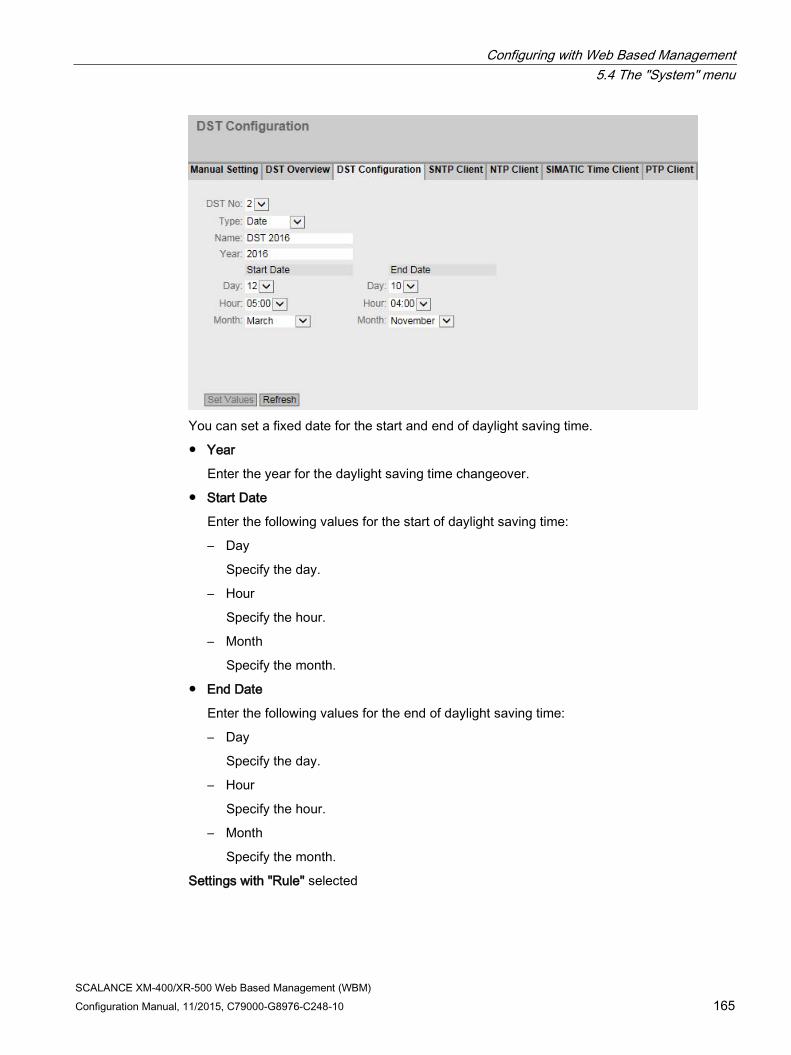
Configuring with Web Based Management 5.4 The "System" menu
SCALANCE XM-400/XR-500 Web Based Management (WBM) Configuration Manual, 11/2015, C79000-G8976-C248-10 165
You can set a fixed date for the start and end of daylight saving time.
● Year
Enter the year for the daylight saving time changeover.
● Start Date
Enter the following values for the start of daylight saving time:
– Day
Specify the day.
– Hour
Specify the hour.
– Month
Specify the month.
● End Date
Enter the following values for the end of daylight saving time:
– Day
Specify the day.
– Hour
Specify the hour.
– Month
Specify the month.
Settings with "Rule" selected
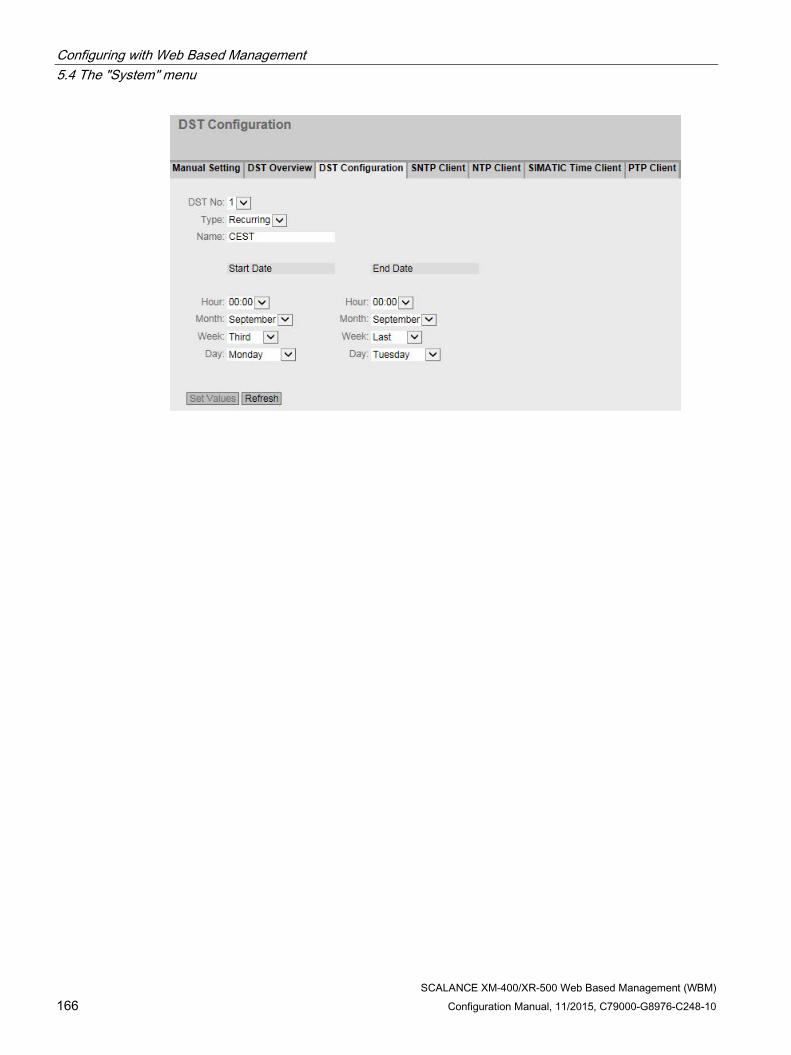
Configuring with Web Based Management 5.4 The "System" menu
SCALANCE XM-400/XR-500 Web Based Management (WBM) 166 Configuration Manual, 11/2015, C79000-G8976-C248-10

Configuring with Web Based Management 5.4 The "System" menu
SCALANCE XM-400/XR-500 Web Based Management (WBM) Configuration Manual, 11/2015, C79000-G8976-C248-10 167
You can create a rule for the daylight saving time changeover.
● Year
Enter the year for the daylight saving time changeover.
● Start Date
Enter the following values for the start of daylight saving time:
– Hour
Specify the hour.
– Month
Specify the month.
– Week
Specify the week.
You can select the first to fourth or the last week of the month.
– Weekday
Specify the weekday.
● End Date
Enter the following values for the end of daylight saving time:
– Hour
Specify the hour.
– Month
Specify the month.
– Week
Specify the week.
You can select the first to fourth or the last week of the month.
– Weekday
Specify the weekday.

Configuring with Web Based Management 5.4 The "System" menu
SCALANCE XM-400/XR-500 Web Based Management (WBM) 168 Configuration Manual, 11/2015, C79000-G8976-C248-10
5.4.11.4 SNTP Client
Time-of-day synchronization in the network SNTP (Simple Network Time Protocol) is used for synchronizing the time in the network. The time frames are sent by an SNTP server in the network.
Description The page contains the following boxes:
● SNTP Client Enable or disable automatic time-of-day synchronization using SNTP.
● Current System Time Shows the current date and current normal time received by the IE switch. If you specify a time zone, the time information is adapted accordingly.
● Last Synchronization Time Shows when the last time-of-day synchronization took place.

Configuring with Web Based Management 5.4 The "System" menu
SCALANCE XM-400/XR-500 Web Based Management (WBM) Configuration Manual, 11/2015, C79000-G8976-C248-10 169
● Last Synchronization Mechanism Shows how the last time synchronization was performed. The following methods are possible:
– Not set The time was not set.
– Manual Manual time setting
– SNTP Automatic time-of-day synchronization with SNTP
– NTP Automatic time-of-day synchronization with NTP
– SIMATIC Automatic time-of-day synchronization using the SIMATIC time frame
– PTP Automatic time-of-day synchronization with PTP
● Time Zone In this box, enter the time zone you are using in the format "+/- HH:MM". The time zone relates to UTC standard world time.
The time in the "Current System Time" box is adapted accordingly.
● Daylight Saving Time (DST) Shows whether the daylight saving time changeover is active.
– active (offset +1 h)
The system time was changed to daylight saving time; in other words an hour was added. You can see the current system time at the top right in the selection area of the WBM.
The normal time including the time zone continues to be displayed in the "Current System Time" box.
– inactive (offset +0 h) The current system time is not changed.
● "SNTP Mode" Select the synchronization mode from the drop-down list. The following types of synchronization are possible:
– Poll If you select this protocol type, the input boxes "SNTP Server Address", "SNTP Server Port and "Poll Interval[s]" are displayed to allow further configuration. With this type of synchronization, the device is active and sends a time query to the SNTP server.
– Listen With this type of synchronization, the device is passive and receives SNTP frames that deliver the time of day.
● SNTP Server Address Enter the IP address or the FQDN (Fully Qualified Domain Name) of the SNTP server.

Configuring with Web Based Management 5.4 The "System" menu
SCALANCE XM-400/XR-500 Web Based Management (WBM) 170 Configuration Manual, 11/2015, C79000-G8976-C248-10
● SNTP Server Port Enter the port of the SNTP server. The following ports are possible:
– 123 (standard port)
– 1025 to 36564
● Poll Interval[s] Here, enter the interval between two-time queries. In this box, you enter the query interval in seconds. Possible values are 16 to 16284 seconds.
Procedure 1. Click the "SNTP Client" check box to enable the automatic time setting.
2. In the "Time Zone" input box, enter the local time difference to world time (UTC). The input format is "+/-HH:MM" (for example +02:00 for CEST), because the SNTP server always sends the UTC time. This time is then recalculated and displayed as the local time based on the specified time zone. On the device itself, there is no changeover from the daylight saving to standard time. You also need to take this into account when completing the "Time Zone" input box.
3. Select one of the following options from the "SNTP Mode" drop-down list:
– Poll For this mode, you need to configure the following: - time zone difference (step 2) - time server (step 4) - Port (step 5) - query interval (step 6) - complete the configuration with step 7.
– Listen For this mode, you need to configure the following: - time difference to the time sent by the server (step 2) - complete the configuration with step 7.
4. In the "SNTP Server Address" input box, enter the IPv4 address or the FQDN of the SNTP server whose frames will be used to synchronize the time of day.
5. In the "SNTP Server Port" input box, enter the port via which the SNTP server is available. The port can only be modified if the IPv4 address or the FQDN name of the SNTP server is entered.
6. In the "Poll Interval[s]" input box, enter the time in seconds after which a new time query is sent to the time server.
7. Click the "Set Values" button to transfer your changes to the device.
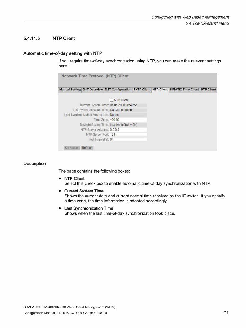
Configuring with Web Based Management 5.4 The "System" menu
SCALANCE XM-400/XR-500 Web Based Management (WBM) Configuration Manual, 11/2015, C79000-G8976-C248-10 171
5.4.11.5 NTP Client
Automatic time-of-day setting with NTP If you require time-of-day synchronization using NTP, you can make the relevant settings here.
Description The page contains the following boxes:
● NTP Client Select this check box to enable automatic time-of-day synchronization with NTP.
● Current System Time Shows the current date and current normal time received by the IE switch. If you specify a time zone, the time information is adapted accordingly.
● Last Synchronization Time Shows when the last time-of-day synchronization took place.

Configuring with Web Based Management 5.4 The "System" menu
SCALANCE XM-400/XR-500 Web Based Management (WBM) 172 Configuration Manual, 11/2015, C79000-G8976-C248-10
● Last Synchronization Mechanism Shows how the last time synchronization was performed. The following methods are possible:
– Not set The time was not set.
– Manual Manual time setting
– SNTP Automatic time-of-day synchronization with SNTP
– NTP Automatic time-of-day synchronization with NTP
– SIMATIC Automatic time-of-day synchronization using the SIMATIC time frame
– PTP Automatic time-of-day synchronization with PTP
● Time Zone In this box, enter the time zone you are using in the format "+/- HH:MM". The time zone relates to UTC standard world time.
The time in the "Current System Time" box is adapted accordingly.
● Daylight Saving Time (DST) Shows whether the daylight saving time changeover is active.
– active (offset +1 h)
The system time was changed to daylight saving time; in other words an hour was added. You can see the current system time at the top right in the selection area of the WBM.
The normal time including the time zone continues to be displayed in the "Current System Time" box.
– inactive (offset +0 h) The current system time is not changed.
● NTP Server Address Enter the IPv4 address or the FQDN (Fully Qualified Domain Name) of the NTP server.
● NTP Server Port Enter the port of the NTP server. The following ports are possible:
– 123 (standard port)
– 1025 to 36564
● Poll Interval[s] Here, enter the interval between two-time queries. In this box, you enter the query interval in seconds. Possible values are 64 to 1024 seconds.

Configuring with Web Based Management 5.4 The "System" menu
SCALANCE XM-400/XR-500 Web Based Management (WBM) Configuration Manual, 11/2015, C79000-G8976-C248-10 173
Procedure 1. Click the "NTP Client" check box to enable the automatic time setting using NTP.
2. Enter the necessary values in the following boxes:
– Time zone
– IPv4 address or FQDN of the NTP server
– NTP server port
– Query interval
3. Click the "Set Values" button.
5.4.11.6 SIMATIC time client
Time setting via SIMATIC time client
Description The page contains the following boxes:
● SIMATIC Time Client Select this check box to enable the device as a SIMATIC time client.
● Current System Time Shows the current system time.

Configuring with Web Based Management 5.4 The "System" menu
SCALANCE XM-400/XR-500 Web Based Management (WBM) 174 Configuration Manual, 11/2015, C79000-G8976-C248-10
● Last Synchronization Time Shows when the last time-of-day synchronization took place.
● Last Synchronization Mechanism Shows how the last time synchronization was performed. The following methods are possible:
– Not set The time was not set.
– Manual Manual time setting
– SNTP Automatic time-of-day synchronization with SNTP
– NTP Automatic time-of-day synchronization with NTP
– SIMATIC Automatic time-of-day synchronization using the SIMATIC time frame
– PTP Automatic time-of-day synchronization with PTP
Procedure 1. Click the "SIMATIC Time Client" check box to enable the SIMATIC Time Client.
2. Click the "Set Values" button.
5.4.11.7 PTP Client The following devices support time-of-day synchronization using PTP:
● SCALANCE XR528-6M
● SCALANCE XR552-12M
5.4.11.8 PTP Client
Automatic time-of-day setting with PTP If you require time-of-day synchronization using PTP, you can make the relevant settings here.

Configuring with Web Based Management 5.4 The "System" menu
SCALANCE XM-400/XR-500 Web Based Management (WBM) Configuration Manual, 11/2015, C79000-G8976-C248-10 175
Description The page contains the following boxes:
● PTP Client Select this check box to enable automatic time-of-day synchronization with PTP.
● Current System Time Shows the current date and current normal time obtained due to time synchronization in the network. If you specify a time zone, the time information is adapted accordingly.
● Last Synchronization Time Shows when the last time-of-day synchronization took place.
● Last Synchronization Mechanism Shows how the last time synchronization was performed. The following methods are possible:
– Not set The time was not set.
– Manual Manual time setting
– SNTP Automatic time-of-day synchronization with SNTP
– NTP Automatic time-of-day synchronization with NTP
– SIMATIC Automatic time-of-day synchronization using the SIMATIC time frame
– PTP Automatic time-of-day synchronization with PTP

Configuring with Web Based Management 5.4 The "System" menu
SCALANCE XM-400/XR-500 Web Based Management (WBM) 176 Configuration Manual, 11/2015, C79000-G8976-C248-10
● Time Zone In this box, enter the time zone you are using in the format "+/- HH:MM". The time zone relates to UTC standard world time.
The time in the "Current System Time" box is adapted accordingly.
● Daylight Saving Time (DST) Shows whether the daylight saving time changeover is active.
– active (offset +1 h)
The system time was changed to daylight saving time; in other words an hour was added. You can see the current system time at the top right in the selection area of the WBM.
The normal time including the time zone continues to be displayed in the "Current System Time" box.
– inactive (offset +0 h) The current system time is not changed.
Procedure 1. Click the "PTP Client" check box to enable the automatic time setting using PTP.
2. Specify the a time zone, if applicable.
3. Click the "Set Values" button.
5.4.12 Automatic logout
Setting the automatic logout On this page, set the times after which there is an automatic logout from WBM or the CLI following user in activity.
If you have been logged out automatically, you will need to log in again.

Configuring with Web Based Management 5.4 The "System" menu
SCALANCE XM-400/XR-500 Web Based Management (WBM) Configuration Manual, 11/2015, C79000-G8976-C248-10 177
Configuration 1. Enter a value of 60-3600 seconds in the "Web Base Management [s]" input box. If you
enter the value 0, the automatic logout is disabled.
2. Enter a value of 60-600 seconds in the "CLI (TELNET, SSH, Serial) [s]" input box. If you enter the value 0, the automatic logout is disabled.
3. Click the "Set Values" button.
5.4.13 Configuration of the SELECT/SET button
Description of the SELECT/SET button The "SELECT/SET" button is used for the following:
● Changing the display mode,
● Resetting to factory defaults,
● Defining the fault mask and the LED display.
You will find a detailed description of the individual functions available with the buttons in the device operating instructions.
On this page, the functionality of the SELECT/SET button can be restricted or fully disabled.

Configuring with Web Based Management 5.4 The "System" menu
SCALANCE XM-400/XR-500 Web Based Management (WBM) 178 Configuration Manual, 11/2015, C79000-G8976-C248-10
Description of the displayed boxes The following functions are possible:
● Restore Factory Defaults Enable or disable the "Restore Factory Defaults" function with the Select/set button.
CAUTION
Button function "Restore Factory Defaults" active during startup
If you have disabled this function in your configuration, disabling is only valid during operation. When restarting, for example after power down, the function is active until the configuration is loaded so that the device can inadvertently be reset to the factory settings. This may cause unwanted disruption in network operation since the device needs to be reconfigured if this occurs. An inserted PLUG is also deleted and returned to the status as shipped.
● Redundancy Manager
Enables/disables the redundancy manager function.
● Set Fault Mask Enable or disable the function "Define fault mask via the LED display" with the SELECT/SET button.
Steps in configuration 1. To use the required functionality, select the corresponding check box.
2. Click the "Set Values" button.

Configuring with Web Based Management 5.4 The "System" menu
SCALANCE XM-400/XR-500 Web Based Management (WBM) Configuration Manual, 11/2015, C79000-G8976-C248-10 179
5.4.14 Syslog Client
System event agent Syslog according to RFC 3164 is used for transferring short, unencrypted text messages over UDP in the IP network. This requires a Syslog server.
Requirements for sending log entries: ● The Syslog function is enabled on the device.
● The Syslog function is enabled for the relevant event.
● There is a Syslog server in your network that receives the log entries. (Since this is a UDP connection, there is no acknowledgment to the sender)
● The IP address or the FQDN (Fully Qualified Domain Name) of the Syslog server is entered in the device.
Description The page contains the following boxes:
● Syslog Client Enable or disable the Syslog function.
● Syslog Server Address Enter the IP address or the FQDN (Fully Qualified Domain Name) of the Syslog server.
This table contains the following columns
● Select Select the row you want to delete.
● Syslog Server Address Shows the IP address or the FQDN (Fully Qualified Domain Name) of the Syslog server.
● Server Port Enter the port of the Syslog server being used.

Configuring with Web Based Management 5.4 The "System" menu
SCALANCE XM-400/XR-500 Web Based Management (WBM) 180 Configuration Manual, 11/2015, C79000-G8976-C248-10
Procedure Enabling function
1. Select the "Syslog Client" check box.
2. Click the "Set Values" button.
Creating a new entry
1. In the "Syslog Server Address" input box, enter the IP address or the FQDN of the Syslog server on which the log entries will be saved.
2. Click the "Create" button. A new row is inserted in the table.
3. In the "Server Port" input box, enter the number of the UDP port of the server.
4. Click the "Set Values" button.
Note
The default setting of the server port is 514.
Changing the entry
1. Delete the entry.
2. Create a new entry.
Deleting an entry
1. Select the check box in the row to be deleted.
2. Click the "Delete" button. All selected entries are deleted and the display is refreshed.

Configuring with Web Based Management 5.4 The "System" menu
SCALANCE XM-400/XR-500 Web Based Management (WBM) Configuration Manual, 11/2015, C79000-G8976-C248-10 181
5.4.15 Ports
5.4.15.1 Overview
Overview of the port configuration The page shows the configuration for the data transfer for all ports of the device. You cannot configure anything on this page.
Description of the displayed boxes The table has the following columns:
● Port Shows the configurable ports. The entry is a link. If you click on the link, the corresponding configuration page is opened. The port is made up of the module number and the port number, for example port 0.1 is module 0, port 1.
● Port name Shows the name of the port.
● Port Type (only with routing) Shows the type of the port. The following types are possible:
– Router port
– Switch Port VLAN Hybrid
– Switch-Port VLAN Trunk

Configuring with Web Based Management 5.4 The "System" menu
SCALANCE XM-400/XR-500 Web Based Management (WBM) 182 Configuration Manual, 11/2015, C79000-G8976-C248-10
● Combo Port Media Type
This column contains a value only with combo ports.
Shows the mode of the combo port:
– auto
– rj45
– sfp
● Status Shows whether the port is on or off. Data traffic is possible only over an enabled port.
● OperState Displays the current operational status. The operational status depends on the configured "Status" and the "Link". The available options are as follows:
– up You have configured the status "enabled" for the port and the port has a valid connection to the network.
– down You have configured the status "disabled" or "Link down" for the port or the port has no connection.
– not present With modular devices, this status is displayed when, for example, no media module is inserted.
● Link Shows the connection status to the network. With the connection status, the following is possible:
– up The port has a valid link to the network, a link integrity signal is being received.
– down The link is down, for example because the connected device is turned off.
● Curr. transfer mode Shows the transfer parameters of the port.
● MTU (Maximum Transmission Unit) Shows the packet size.
● Negotiation Shows whether the automatic configuration is enabled or disabled.
● Flow Ctrl. Type Shows whether flow control is enabled or disabled for the port.
● Flow Ctrl. Shows whether flow control is working on this port.

Configuring with Web Based Management 5.4 The "System" menu
SCALANCE XM-400/XR-500 Web Based Management (WBM) Configuration Manual, 11/2015, C79000-G8976-C248-10 183
● MAC Address
Shows the MAC address of the port.
● Blocked by
Shows why the port is in the "blocked" status:
– -
The analysis of the port status Is not supported.
– forwarding
The port is not blocked.
– ring-redundancy
The port belongs to a redundancy manager. When the redundancy manager is in the "Passive status, one of the ring ports is in the "blocking" status.
– spanning-tree
The port has the status "Discarding" in the spanning tree. The port is part of a spanning tree, however it is located on a redundant path and is deactivated for data traffic.
– loop detection
A loop was detected and as the reaction to a loop, the status "disable" was configured for the port.
– down-in-bundle
The port is part of a link aggregation and was deactivated by LACP.
– la-loop-detection
The port is part of a link aggregation. A loop was detected and as the reaction to a loop, the status "disable" was configured for the link aggregation.
– la-spanning-tree
The port is part of a link aggregation. Thelink aggregation was switched to the status "Discarding" by the spanning tree.
– admin-down
The status "disabled" is configured for the port, see "System > Ports > Configuration".
– link down
The status "enabled" is configured for the port but there is no connection, see "System > Ports > Configuration".
– power-down
The status "Lin down" is configured for the port, see "System > Ports > Configuration".
– standby
Standby redundancy is enabled on the device. The port is a standby port with the status "Passive".

Configuring with Web Based Management 5.4 The "System" menu
SCALANCE XM-400/XR-500 Web Based Management (WBM) 184 Configuration Manual, 11/2015, C79000-G8976-C248-10
Deviating display of the transmission parameters with combo ports In the connection status "down", the displayed transmission parameters do not match the actual values of the combo port. In the connection status "up", the correct values are displayed.
Initial situation
A pluggable transceiver is plugged into the combo port with the following settings:
● Combo Port Media Type: auto
● Status: enabled
● Link: down
Display of the transmission parameters
With 100 Mbps pluggable transceivers
● Actual response: Mode: 1G HD
● Expected response: Mode: 100M FD
With 1 Gbps pluggable transceivers
● Actual response: Mode: 1G HD
● Expected response: Mode: 1G FD

Configuring with Web Based Management 5.4 The "System" menu
SCALANCE XM-400/XR-500 Web Based Management (WBM) Configuration Manual, 11/2015, C79000-G8976-C248-10 185
5.4.15.2 Configuration
Configuring ports With this page, you can configure all the ports of the device.
Description of the displayed boxes The table has the following rows:
● Port Select the port to be configured from the drop-down list. The port is made up of the module number and the port number, for example port 0.1 is module 0, port 1.
● Status Specify whether the port is enabled or disabled.
– enabled The port is enabled. Data traffic is possible only over an enabled port.
– disabled The port is disabled but the connection remains.
– link down The port is disabled and the connection to the partner device is terminated.
● Port Name Enter a name for the port here.
● MAC Address Shows the MAC address of the port.

Configuring with Web Based Management 5.4 The "System" menu
SCALANCE XM-400/XR-500 Web Based Management (WBM) 186 Configuration Manual, 11/2015, C79000-G8976-C248-10
● "Mode Type From this drop-down list, select the transmission speed and the transfer mode of the port. If you set the mode to "Auto negotiation", these parameters are automatically negotiated with the connected end device. This must also be in the "Autonegotiation" mode.
Note
Before the port and partner port can communicate with each other, the settings must match at both ends.
Note
"Mode Type" with combo ports
To be able to set the "Mode Type" of a combo port, change the "Combo Port Media Type" to "rj45".
If "auto" is set for the "Combo Port Media Type" and the RJ-45 port is used, you cannot set the "Mode Type".
● "Mode Shows the transmission speed and the transfer mode of the port. The transmission speed can be 10 Mbps, 100 Mbps, 1000 Mbps or 10 Gbps. As the transmission mode, you can configure full duplex (FD) or half duplex (HD).
● Negotiation Shows whether the automatic configuration of the connection to the partner port is enabled or disabled.
Note
Turning flow control on/off with autonegotiation
Flow control can only be enabled or disabled if the "autonegotiation" function is turned off. The function cannot enabled again afterwards.
● Flow Ctrl. Type Enable or disable flow control for the port.
● Flow Ctrl. Shows whether flow control is working on this port.
● MTU Enter the packet size.
● Port Type(only with routing) Select the type of port from the drop-down list.
– Router port
The port is a layer 3 interface. It does not support layer 2 functions.
– Switch Port VLAN Hybrid
The port sends tagged and untagged frames. It is not automatically a member of a VLAN.
– Switch-Port VLAN Trunk
The port only sends tagged frames and is automatically a member of all VLANs.

Configuring with Web Based Management 5.4 The "System" menu
SCALANCE XM-400/XR-500 Web Based Management (WBM) Configuration Manual, 11/2015, C79000-G8976-C248-10 187
● Combo Port Media Type
Specify the mode of the combo port:
– auto
If you select this mode, the SFP transceiver port has priority.
As soon as an SFP transceiver is plugged in, an existing connection at the fixed RJ-45 port is terminated. If no SFC transceiver is plugged in, a connection can be established via the fixed RJ-45 port.
– rj45
If you select this mode, the fixed RJ-45 port is used regardless of the SFP transceiver port.
If an SFP transceiver is plugged in, it is disabled and the power turned off.
– sfp
If you select this mode, the SFP transceiver port is used regardless of the built-in RJ-45 port.
If an RJ-45 connection is established, it is terminated because the power of the RJ-45 port is turned off.
The factory setting for the combo ports is the auto mode.
● OperState Displays the current operational status. The operational status depends on the configured "Status" and the "Link". The available options are as follows:
– up You have configured the status "enabled" for the port and the port has a valid connection to the network.
– down You have configured the status "disabled" or "Link down" for the port or the port has no connection.
– not present With modular devices, this status is displayed when, for example, no media module is inserted.

Configuring with Web Based Management 5.4 The "System" menu
SCALANCE XM-400/XR-500 Web Based Management (WBM) 188 Configuration Manual, 11/2015, C79000-G8976-C248-10
● Link Shows the connection status to the network. The available options are as follows:
– up The port has a valid link to the network, a link integrity signal is being received.
– down The link is down, for example because the connected device is turned off.
● Blocked by
Shows why the port is in the "blocked" status:
– -
The analysis of the port status Is not supported.
– forwarding
The port is not blocked.
– ring-redundancy
The port belongs to a redundancy manager. When the redundancy manager is in the "Passive status, one of the ring ports is in the "blocking" status.
– spanning-tree
The port has the status "Discarding" in the spanning tree. The port is part of a spanning tree, however it is located on a redundant path and is deactivated for data traffic.
– loop detection
A loop was detected and as the reaction to a loop, the status "disable" was configured for the port.
– down-in-bundle
The port is part of a link aggregation and was deactivated by LACP.
– la-loop-detection
The port is part of a link aggregation. A loop was detected and as the reaction to a loop, the status "disable" was configured for the link aggregation.
– la-spanning-tree
The port is part of a link aggregation. Thelink aggregation was switched to the status "Discarding" by the spanning tree.
– admin-down
The status "disabled" is configured for the port, see "System > Ports > Configuration".
– link down
The status "enabled" is configured for the port but there is no connection, see "System > Ports > Configuration".
– power-down
The status "Lin down" is configured for the port, see "System > Ports > Configuration".
– standby

Configuring with Web Based Management 5.4 The "System" menu
SCALANCE XM-400/XR-500 Web Based Management (WBM) Configuration Manual, 11/2015, C79000-G8976-C248-10 189
Standby redundancy is enabled on the device. The port is a standby port with the status "Passive".
Changing the port configuration Click the appropriate box to change the configuration.
Note
Optical ports only work with the full duplex mode and at maximum transmission rate. As a result, the following settings cannot be made for optical ports: • Automatic configuration • Transmission speed • Transmission technique
Note
With various automatic functions, the device prevents or reduces the effect on other ports and priority classes (Class of Service) if a port is overloaded. This can mean that frames are discarded even when flow control is enabled.
Port overload occurs when the device receives more frames than it can send, for example as the result of different transmission speeds.
Steps in configuration 1. Change the settings according to your configuration.
2. Click the "Set Values" button.
5.4.16 Fault Monitoring
5.4.16.1 Power Supply
Settings for monitoring the power supply Configure whether or not the power supply should be monitored by the messaging system. Depending on the hardware variant there are one or two power connectors (Line 1 / Line 2). With a redundant power supply, configure the monitoring separately for each individual feed-in line.

Configuring with Web Based Management 5.4 The "System" menu
SCALANCE XM-400/XR-500 Web Based Management (WBM) 190 Configuration Manual, 11/2015, C79000-G8976-C248-10
A fault is then signaled by the message system when there is no power on one of the monitored lines (line 1 or line 2) or when the voltage is too low.
Note
You will find the permitted operating voltage limits in the compact operating instructions of the device.
A fault causes the signaling contact to trigger and the fault LED on the device to light up and, depending on the configuration, can trigger a trap, an e-mail, or an entry in the event log table.
Procedure 1. Click the check box in front of the line name you want to monitor to enable or disable the
monitoring function.
2. Click the "Set Values" button.

Configuring with Web Based Management 5.4 The "System" menu
SCALANCE XM-400/XR-500 Web Based Management (WBM) Configuration Manual, 11/2015, C79000-G8976-C248-10 191
5.4.16.2 Link Change
Configuration of fault monitoring of status changes on connections On this page, you configure whether or not an error message is triggered if there is a status change on a network connection.
If connection monitoring is enabled, an error is signaled
● when there should be a link on a port and this is missing.
● or when there should not be a link on a port and a link is detected.
A fault causes the signaling contact to trigger and the fault LED on the device to light up and, depending on the configuration, can trigger a trap, an e-mail, or an entry in the event log table.
Description of the displayed boxes Table 1 has the following columns:
● 1st column Shows that the settings are valid for all ports.
● Setting Select the setting from the drop-down list. You have the following setting options:
– "-" (disabled)
– Up
– Down
– No Change: The setting in table 2 remains unchanged.
● Copy to Table
If you click the button, the setting is adopted for all ports of table 2.

Configuring with Web Based Management 5.4 The "System" menu
SCALANCE XM-400/XR-500 Web Based Management (WBM) 192 Configuration Manual, 11/2015, C79000-G8976-C248-10
Table 2 has the following columns:
● Port Shows the available ports and link aggregations. The port is made up of the module number and the port number, for example port 0.1 is module 0, port 1.
● Setting
Select the setting from the drop-down list. You have the following options:
– Up Error handling is triggered when the port changes to the active status.
(From "Link down" to "Link up")
– Down Error handling is triggered when the port changes to the inactive status.
(From "Link up" to "Link down")
– "-" (disabled) The error handling is not triggered.
Steps in configuration Configure error monitoring for a port
1. From the relevant drop-down list, select the options of the slots / ports whose connection status you want to monitor.
2. Click the "Set Values" button.
Configure error monitoring for all ports
1. Select the required setting from the drop-down list of the "Setting"column.
2. Click the "Copy to table" button. The setting is adopted for all ports of table 2.
3. Click the "Set Values" button.

Configuring with Web Based Management 5.4 The "System" menu
SCALANCE XM-400/XR-500 Web Based Management (WBM) Configuration Manual, 11/2015, C79000-G8976-C248-10 193
5.4.16.3 Redundancy On this page, you configure whether or not an error message is triggered if there is a status change on a network connection.
Setting ● Redundancy loss (HRP only)
Enable or disable connection monitoring. If the redundancy of the connection is lost, an error is signaled.
5.4.17 PNIO
Settings for PROFINET IO This page shows the PROFINET IO AR status and the device name.
Description of the displayed boxes The page contains the following boxes:
● PNIO AR Status This box shows the status of the PROFINET IO connection; in other words whether the device is connected to a PROFINET IO controller "Online " or "Offline". Here, online means that a connection to a PROFINET IO controller exists, that this has downloaded its configuration data to the device and that the device can send status data to the PROFINET IO controller. In this status known as "in data exchange", the parameters set with the PROFINET IO controller cannot be configured.
● PNIO Name of Station This box displays the PROFINET IO device name according to the configuration in HW Config of STEP 7.

Configuring with Web Based Management 5.4 The "System" menu
SCALANCE XM-400/XR-500 Web Based Management (WBM) 194 Configuration Manual, 11/2015, C79000-G8976-C248-10
5.4.18 PLUG
5.4.18.1 Configuration
NOTICE
Do not remove or insert a C-PLUG / KEY-PLUG during operation!
A PLUG may only be removed or inserted when the device is turned off. The device checks whether or not a PLUG is present at one second intervals. If it is detected that the PLUG was removed, there is a restart. If a valid KEY-PLUG was inserted in the device, the device changes to a defined error state following the restart.
Information about the configuration of the C-PLUG / KEY-PLUG This page provides detailed information about the configuration stored on the C-PLUG or KEY-PLUG. It is also possible to reset the PLUG to "factory defaults" or to load it with new contents.
Note
The action is only executed after you click the "Set Values" button.
The action cannot be undone.
If you decide against executing the function after making your selection, click the "Refresh" button. As a result the data of this page is read from the device again and the selection is canceled.
Note Incompatibility with previous versions with PLUG inserted
During the installation of a previous version, the configuration data can be lost. In this case, the device starts up with the factory settings after the firmware has been installed. In this situation, if a PLUG is inserted in the device, following the restart, this has the status "Not Accepted" since the PLUG still has the configuration data of the previous more up-to-date firmware. This allows you to return to the previous, more up-to-date firmware without any loss of configuration data.
If the original configuration on the PLUG is no longer required, the PLUG can be deleted or rewritten manually using "System > PLUG".

Configuring with Web Based Management 5.4 The "System" menu
SCALANCE XM-400/XR-500 Web Based Management (WBM) Configuration Manual, 11/2015, C79000-G8976-C248-10 195
Description of the displayed boxes The table has the following rows:
● Status Shows the status of the PLUG. The following are possible:
– ACCEPTED There is a PLUG with a valid and suitable configuration in the device.
– NOT ACCEPTED Invalid or incompatible configuration on the inserted PLUG.
– NOT PRESENT There is no C-PLUG or KEY-PLUG inserted in the device.
– FACTORY PLUG is inserted and does not contain a configuration. This status is also displayed when the PLUG was formatted during operation.
– MISSING There is no PLUG inserted. Functions are configured on the device for which a license is required.
● Device Group Shows the SIMATIC NET product line that used the C-PLUG or KEY-PLUG previously.

Configuring with Web Based Management 5.4 The "System" menu
SCALANCE XM-400/XR-500 Web Based Management (WBM) 196 Configuration Manual, 11/2015, C79000-G8976-C248-10
● Device Type Shows the device type within the product line that used the C-PLUG or KEY-PLUG previously.
● Configuration Revision The version of the configuration structure. This information relates to the configuration options supported by the device and has nothing to do with the concrete hardware configuration. This revision information does not therefore change if you add or remove additional components (modules or extenders), it can, however, change if you update the firmware.
● File System Displays the type of file system on the PLUG.
NOTICE
New file system UBI
As of firmware version 3.0, UBI is the standard file system for the C-PLUG or KEY-PLUG. If a C-PLUG with the previous file system IECP is detected in such a device, this C-PLUG will be formatted for the UBI file system and the data will be rewritten to the C-PLUG.
This change in the file system also occurs following a firmware update to V3.0. A downgrade to the previous version of the firmware then presents a problem. The firmware can neither read nor write the C-PLUG or KEY-PLUG and it is not even possible to "Erase PLUG to Factory Default".
● File System Size [bytes] Shows the maximum storage capacity of the file system on the C-PLUG.
● File System Usage [bytes] Displays the storage space in use in the file system of the C-PLUG.
● Info String Shows additional information about the device that used the PLUG previously, for example, order number, type designation, and the versions of the hardware and software. The displayed software version corresponds to the version in which the configuration was last changed. With the "NOT ACCEPTED" status, further information on the cause of the problem is displayed.
● "Modify PLUG Select the setting from the drop-down list. You have the following options for changing the configuration on the C-PLUG or KEY-PLUG:
– Write Current Configuration to the PLUG This option is available only if the status of the PLUG is "NOT ACCEPTED" or "FACTORY". The configuration in the internal flash memory of the device is copied to the PLUG.
– Erase PLUG to factory default Deletes all data from the C-PLUG and triggers low-level formatting.

Configuring with Web Based Management 5.4 The "System" menu
SCALANCE XM-400/XR-500 Web Based Management (WBM) Configuration Manual, 11/2015, C79000-G8976-C248-10 197
Steps in configuration 1. You can only make settings in this box if you are logged on as "Administrator". Here, you
decide how you want to change the content of the PLUG.
2. Select the required option from the "Modify PLUG" drop-down list.
3. Click the "Set Values" button.
5.4.18.2 License
NOTICE
Do not remove or insert a C-PLUG / KEY-PLUG during operation!
A PLUG may only be removed or inserted when the device is turned off. The device checks whether or not a PLUG is present at one second intervals. If it is detected that the PLUG was removed, there is a restart. If a valid KEY-PLUG was inserted in the device, the device changes to a defined error state following the restart.
If the device was configured at some time with a PLUG, the device can no longer be used without this PLUG. To be able to use the device again, reset the device to the factory settings.
Note Incompatibility with previous versions with PLUG inserted
During the installation of a previous version, the configuration data can be lost. In this case, the device starts up with the factory settings after the firmware has been installed. In this situation, if a PLUG is inserted in the device, following the restart, this has the status "Not Accepted" since the PLUG still has the configuration data of the previous more up-to-date firmware. This allows you to return to the previous, more up-to-date firmware without any loss of configuration data.
If the original configuration on the PLUG is no longer required, the PLUG can be deleted or rewritten manually using "System > PLUG".

Configuring with Web Based Management 5.4 The "System" menu
SCALANCE XM-400/XR-500 Web Based Management (WBM) 198 Configuration Manual, 11/2015, C79000-G8976-C248-10
Information about the license of the KEY-PLUG A C-PLUG can only store the configuration of a device. In addition to the configuration, a KEY-PLUG also contains a license that enables certain functions of your SIMATIC NET device.
This page provides detailed information about the license on the KEY-PLUG. In this example, the KEY-PLUG contains the data for enabling the layer 3 functions of the device.
Description of the displayed boxes ● Status
Shows the status of the KEY-PLUG. The following are possible:
– ACCEPTED The KEY-PLUG in the device contains a suitable and valid license.
– NOT ACCEPTED The license of the inserted KEY-PLUG is not valid.
– NOT PRESENT No KEY-PLUG is inserted in the device.
– MISSING There is no KEY-PLUG or a C-PLUG with the status "FACTORY" inserted in the device. Functions are configured on the device for which a license is required.
– WRONG The inserted KEY-PLUG is not suitable for the device.
– UNKNOWN Unknown content of the KEY-PLUG.
– DEFECTIVE The content of the KEY-PLUG contains errors.
● Order ID Shows the order number of the KEY-PLUG. The KEY-PLUG is available for various functional enhancements and for various target systems.

Configuring with Web Based Management 5.4 The "System" menu
SCALANCE XM-400/XR-500 Web Based Management (WBM) Configuration Manual, 11/2015, C79000-G8976-C248-10 199
● Serial Number Shows the serial number of the KEY-PLUG.
● Info String Shows additional information about the device that used the KEY-PLUG previously, for example, order number, type designation, and the versions of the hardware and software. The displayed software version corresponds to the version in which the configuration was last changed. With the "NOT ACCEPTED" status, further information on the cause of the problem is displayed.
Note
When you save the configuration, the information about whether or not a KEY-PLUG was inserted in the device at the time is also saved. This configuration can then only work if a KEY-PLUG with the same order number / license is inserted.
5.4.19 Ping
Reachability of an address in an IPv4 network With the ping function, you can check whether a certain IPv4 address is reachable in the network.

Configuring with Web Based Management 5.4 The "System" menu
SCALANCE XM-400/XR-500 Web Based Management (WBM) 200 Configuration Manual, 11/2015, C79000-G8976-C248-10
Description The table has the following columns:
● IP Address Enter the IPv4 address of the device.
● Repeat Enter the number of ping requests.
● Ping Click this button to start the ping function.
● Ping Output This box shows the output of the ping function.
● Clear Click this button to empty the "Ping Output" box.
5.4.20 PoE
Note
The "PoE" menu item is only displayed with devices that support PoE.
5.4.20.1 General
Settings for Power over Ethernet (PoE) On this page, you see information about the power that the IE switch supplies with PoE.
The SCALANCE XR-500 represents a PSE (Power Sourcing Equipment). With the SCALANCE XM-400, each group of four ports with PoE capability is known as a PSE. The displayed values apply only to the corresponding PSE.

Configuring with Web Based Management 5.4 The "System" menu
SCALANCE XM-400/XR-500 Web Based Management (WBM) Configuration Manual, 11/2015, C79000-G8976-C248-10 201
Description of the displayed boxes ● PSE (read-only)
Shows the number of the PSE.
● Maximum Power [W] (read-only)
Maximum power that a PSE provides to supply PoE devices.
The "Maximum Power" value can be set for a SCALANCE XM-400.
● Allocated Power [W] (read-only)
Sum of the power reserved by the PoE devices according to the "Classification".
● Power in Use [W] (read-only)
Sum of the power used by the end devices.
● Usage Threshold [%]
As soon as the power being used by the end devices exceeds the percentage shown here, an event is triggered.
Power over Ethernet with SCALANCE XM-400 With a SCALANCE XM-400, you can use the "Power over Ethernet" function via the port extender PE408PoE.
PoE power supply
The connection of the PoE power supply is external. You can connect 2 PoE power supplies with each PE408PoE port extender. Each PE408PoE therefore has 2 PSE units (Power Sourcing Equipment) each with 4 ports.
Numbering of the PSE units
To be able to differentiate between the PSE units in the configuration, they are numbered:
Figure 5-8 SCALANCE XM-400 with 2 PE408PoE port extenders
If a PE408PoE is inserted in slot 2, its two PSE slots have indexes 1 and 2. If a PE408PoE is inserted in slot 3, its two PSE slots have indexes 3 and 4.

Configuring with Web Based Management 5.4 The "System" menu
SCALANCE XM-400/XR-500 Web Based Management (WBM) 202 Configuration Manual, 11/2015, C79000-G8976-C248-10
The numbering of the PSE units is decided by the slots. If there is a port extender without PoE in slot 2, and there is a PE408PoE in slot 3, the PSE units in slot 3 still have the indexes 3 and 4.
Figure 5-9 SCALANCE XM-400 with 2 port extenders (1 port extender without PoE and 1
PE408PoE)
With a SCALANCE XM416-4C with which you can only connect one port extender, the indexes of the PSE units are 1 and 2.
Power over Ethernet with SCALANCE XR528-6M and SCALANCE XR552-12M With SCALANCE XR528-6M and SCALANCE XR552-12M only the module slots 1 to 3 can be fitted with PoE modules.
5.4.20.2 Port
Settings for the ports For each individual PoE port, you can specify whether or not the power will be supplied via Ethernet. You can also set a priority for each connected powered device (PD). Devices for which a high priority was set, take preference over other devices for the power supply. On this page, you can see detailed information on the individual PoE ports.

Configuring with Web Based Management 5.4 The "System" menu
SCALANCE XM-400/XR-500 Web Based Management (WBM) Configuration Manual, 11/2015, C79000-G8976-C248-10 203
Description of the displayed boxes The page contains two tables. In table 1, you can make settings and assign them to all ports at the same time. In table 2, you can make different settings for each port.
Table 1 has the following columns:
● Port
Shows that the settings are valid for all ports.
● Setting
Select the setting from the drop-down list. You have the following setting options:
– enabled
Enables the function
– disabled
Disables the function
– No Change
The setting in table 2 remains unchanged
● Priority
Select the priority of the ports from the drop-down list. If you set the priority in table 1 and copy the values to table 2, all ports will have the same priority.
The following settings are possible, in ascending order of relevance:
– low
low priority
– high
medium priority
– critical
high priority
– No Change
The setting in table 2 remains unchanged
● Type
Here, you can enter a string to describe the connected device in greater detail. The maximum length is 255 characters.
● Copy to Table
If you click the button, the setting is adopted for all ports of table 2.

Configuring with Web Based Management 5.4 The "System" menu
SCALANCE XM-400/XR-500 Web Based Management (WBM) 204 Configuration Manual, 11/2015, C79000-G8976-C248-10
Table 2 has the following columns:
● Port
Shows the configurable PoE ports. The port is made up of the module number and the port number, for example port 0.1 is module 0, port 1.
● Setting
Enable the PoE power supply for this port or interrupt it.
● Priority
From the drop-down list, select which priority this port will have for the power supply.
The following settings are possible, in ascending order of relevance:
– low
– high
– critical
If the same priority is set for two ports, the port with the lower number will be preferred when necessary.
● Type
Here, you can enter a string to describe the connected device in greater detail. The maximum length is 255 characters.
● Use Custom Maximum Power
If you enable this check box for a port, the user-defined maximum power is used.
● Custom Maximum power [W] (read-only)
Enter the maximum power that a port makes available to supply a connected device.
This value is only taken into account when the "Use Custom Maximum Power" check box is selected.
● Classification (read-only)
The classification specifies the class of the device. From this, it is possible to recognize the maximum power of the device.

Configuring with Web Based Management 5.4 The "System" menu
SCALANCE XM-400/XR-500 Web Based Management (WBM) Configuration Manual, 11/2015, C79000-G8976-C248-10 205
● Status (read-only)
Shows the current status of the port.
The following states are possible:
– disabled
The PoE power supply is deactivated for this port.
– delivering Power
The PoE power supply is activated for this port and a device is connected.
– searching
The PoE power supply is activated for this port but there is no device connected.
Note
If a device is connected to a port with PoE capability, a check is made to determine whether the power of the port is adequate for the connected device.
If the power of the port is inadequate, although PoE is enabled in "Setting ", the port nevertheless has the status "disabled". This means that the port was disabled by the PoE power management.
● Power [mW] (read-only)
Shows the power that the SCALANCE provides for this port.
● Voltage [V] (read-only)
Shows the voltage applied to this port.
● Current [mA] (read-only)
Shows the current with which a device connected to this port is supplied.
5.4.21 Port Diagnostics
5.4.21.1 Cable Tester With this page, each individual Ethernet port can run independent fault diagnostics on the cable. This test is performed without needing to remove the cable, connect a cable tester and install a loopback module at the other end. Short-circuits and cable breaks can be localized to within a few meters.
Note
Please note that this test is permitted only when no data connection is established on the port to be tested.
If, however, there is a data connection to the port to be tested, this is briefly interrupted.
Automatic re-establishment of the connection can fail and then needs to be done manually.

Configuring with Web Based Management 5.4 The "System" menu
SCALANCE XM-400/XR-500 Web Based Management (WBM) 206 Configuration Manual, 11/2015, C79000-G8976-C248-10
Description The page contains the following boxes:
● Port Select the required port from the drop-down list.
● Run Test Activates error diagnostics. The result is shown in the table.
This table contains the following columns:
● Pair Shows the wire pair in the cable.
Note
Wire pairs
Wire pairs 4-5 and 7-8 of 10/100 Mbps network cables are not used.
1000 Mbps or gigabit Ethernet uses all 4 wire pairs.
The wire pair assignment - pin assignment is as follows (DIN 50173):
Pair 1 = pin 4-5
Pair 2 = pin 1-2
Pair 3 = pin 3-6
Pair 4 = pin 7-8
● Status Displays the status of the cable.
● Distance [m] Displays the distance to the cable end, cable break, or short-circuit.

Configuring with Web Based Management 5.4 The "System" menu
SCALANCE XM-400/XR-500 Web Based Management (WBM) Configuration Manual, 11/2015, C79000-G8976-C248-10 207
5.4.21.2 SFP diagnostics On this page, you run independent error diagnostics for each individual SFP port. This test is performed without needing to remove the cable, connect a cable tester or install a loopback module at the other end.
Description The page contains the following boxes:
● Port Select the required port from the drop-down list.
● Refresh Refreshes the display of the values of the set port. The result is shown in the table.
The values are shown in the following boxes:
● Name Shows the name of the interface.
● Model Shows the type of interface.
● Revision Shows the hardware version of the SFP.
● Serial
Shows the serial number of the SFP

Configuring with Web Based Management 5.4 The "System" menu
SCALANCE XM-400/XR-500 Web Based Management (WBM) 208 Configuration Manual, 11/2015, C79000-G8976-C248-10
● Nominal Bit Rate [Mbps]
Shows the nominal bit rate of the interface.
● Max. Link (50.0/125um) [m]
Shows the maximum distance in meters that is possible with this medium.
● Max. Link (62.5/125um) [m]
Shows the maximum distance in meters that is possible with this medium.
The following table shows the values of the SFP transceiver used in this port:
● Temperature [°C]
Shows the temperature of the interface.
● Voltage [V]
Shows the voltage applied to the interface [V].
● Current [mA]
Shows the current consumption of the interface [mA].
● RX Power [mW]
Shows the receive power of the interface [mW].
● Tx Power [uW]
Shows the transmit power of the interface [mW].
● Current column
Shows the current value.
● Low column
Shows the lowest value.
● High column
Shows the highest value.

Configuring with Web Based Management 5.5 The "Layer 2" menu
SCALANCE XM-400/XR-500 Web Based Management (WBM) Configuration Manual, 11/2015, C79000-G8976-C248-10 209
5.5 The "Layer 2" menu
5.5.1 Configuration
Configuring layer 2 On this page, you create a basic configuration for the functions of layer 2. On the configuration pages of these functions, you can make detailed settings. You can also check the settings on the configuration pages.
Description of the displayed boxes ● Protocol Based VLAN
Enable or disable protocol-based VLAN. Other settings in "Layer 2 > VLAN".
● Subnet Based VLAN
Enable or disable subnet-based VLAN. Other settings in "Layer 2 > VLAN".
● Dynamic MAC Aging Enable or disable the "Aging" mechanism. You can configure other settings in "Layer 2 > Dynamic MAC Aging".

Configuring with Web Based Management 5.5 The "Layer 2" menu
SCALANCE XM-400/XR-500 Web Based Management (WBM) 210 Configuration Manual, 11/2015, C79000-G8976-C248-10
● Redundancy Type The following settings are available:
– "-" (disabled) The redundancy function is disabled.
– Spanning Tree If you select this option, you specify the required redundancy mode in the "Redundancy Mode" drop-down list.
– Ring
If you select this option, you specify the required redundancy mode in the "Redundancy Mode" drop-down list.
– Ring with RSTP
If you select this option, the compatibility mode for spanning tree is set permanently to RSTP. In the "Redundancy Mode" drop-down list, you specify the redundancy mode of the ring redundancy.
You can change the current setting in the "Ring Redundancy" and "Spanning Tree" menus.
Note
Restriction relating to ports with the "Ring with RSTP" option
If you have enabled the "Ring with RSTP" option, the following ports must not be included in the spanning tree: • Ring ports • Standby ports • Standby coupling ports

Configuring with Web Based Management 5.5 The "Layer 2" menu
SCALANCE XM-400/XR-500 Web Based Management (WBM) Configuration Manual, 11/2015, C79000-G8976-C248-10 211
● Redundancy Mode
If you select "Ring" or "Ring with RSTP"in the "Redundancy Type" drop-down list, the following options are then available:
– Automatic Redundancy Detection
Select this setting to configure the redundant mode automatically. In "Automatic Redundancy Detection" mode, the IE Switch automatically detects whether or not there is a device with the role of "HRP Manager" in the ring. If there is, the device adopts the role "HRP" client. If no HRP manager is found, all devices with the "Automatic Redundancy Detection" or "MRP Auto Manager" setting negotiate among themselves to establish which device adopts the role of "MRP Manager". The device with the lowest MAC address will always become "MRP Manager". The other devices automatically set themselves to "MRP Client" mode.
– MRP Auto-Manager
Automatic media redundancy manager
– MRP Client
Media redundancy client
– HRP Client
High Speed Redundancy Protocol client
– HRP manager
High Speed Redundancy Protocol manager
If you select "Spanning Tree" in the "Redundancy Type" drop-down list, the following options are then available:
– STP Enabled Spanning Tree Protocol. Typical reconfiguration times with spanning tree are between 20 and 30 seconds. You can configure other settings in "Layer 2 > Spanning Tree".
– RSTP Enabled Rapid Spanning Tree Protocol (RSTP). If a spanning tree frame is detected at a port, this port reverts from RSTP to spanning tree. You can configure other settings in "Layer 2 > Spanning Tree".
Note
When using RSTP (Rapid Spanning Tree Protocol), loops involving duplication of frames or frames being overtaken may occur briefly. If this is not acceptable in your particular application, use the slower standard spanning tree mechanism.

Configuring with Web Based Management 5.5 The "Layer 2" menu
SCALANCE XM-400/XR-500 Web Based Management (WBM) 212 Configuration Manual, 11/2015, C79000-G8976-C248-10
– MSTP Enables Multiple Spanning Tree Protocol (MSTP). You can configure other settings in "Layer 2 > Spanning Tree".
If you select "Ring with RSTP" in the "Redundancy Type" drop-down list, the current redundancy modes of the Spanning tree and ring redundancy are displayed.
● Standby
Enable or disable the standby redundancy function. You will find other settings in "Layer 2 > Ring Redundancy"
● Passive Listening
Enable or disable the passive listening function.
● RMON If you select this check box, Remote Monitoring (RMON) allows diagnostics data to be collected on the device, prepared and read out using SNMP by a network management station that also supports RMON. This diagnostic data, for example port-related load trends, allow problems in the network to be detected early and eliminated. Some of the "Ethernet statistics counters" are part of the RMON function. If you disable RMON, the "Ethernet statistics counter" in "Information > Ethernet statistics" is no longer updated.
● Dynamic Multicast The following settings are possible:
– "-" (disabled)
– IGMP Snooping Enables IGMP (Internet Group Management Protocol). You can configure other settings in "Layer 2 > Multicast > IGMP".
– GMRP Enables GMRP (GARP Multicast Registration Protocol). You can configure other settings in "Layer 2 > Multicast > GMRP".
Note
GMRP and IGMP cannot operate at the same time.
● GVRP Enable or disable "GVRP" (GARP VLAN Registration Protocol). You can configure other settings in "Layer 2 > VLAN > GVRP".
● Mirroring Enable or disable port mirroring. You can configure other settings in "Layer 2 > Mirroring".

Configuring with Web Based Management 5.5 The "Layer 2" menu
SCALANCE XM-400/XR-500 Web Based Management (WBM) Configuration Manual, 11/2015, C79000-G8976-C248-10 213
● Loop Detection Enable or disable the loop detection function. This allows loops in the network to be detected. You will find other settings in "Layer 2 > Loop Detection"
● PTP
The following setting is possible:
– off
The device does not process any PTP messages. PTP messages are, however, forwarded according to the rules of the switch.
– transparent
The device adopts the function of a transparent clock and forwards PTP messages to other nodes while at the same time making entries in the correction field of the PTP message.
You will find other settings in "Layer 2 > PTP"
5.5.2 QoS
5.5.2.1 CoS queue mapping
CoS queue Here, CoS priorities are assigned to certain queues (Traffic Queues).

Configuring with Web Based Management 5.5 The "Layer 2" menu
SCALANCE XM-400/XR-500 Web Based Management (WBM) 214 Configuration Manual, 11/2015, C79000-G8976-C248-10
Description of the displayed boxes The table has the following columns:
● CoS Shows the CoS priority of the incoming packets.
● Queue From the drop-down list, select the forwarding queue (send priority) that is assigned to the CoS priority. The higher the number of the queue, the higher the send priority.
With queues 1 - 6 frames with a lower priority are occasionally processed even if there are frames with high priority in the queue.
With queues 7 - 8 only frames with a high priority are processed as long as there are frames with high priority in the queue.
The service classes (COS) are assigned to the queues as follows:
● COS 0 → Queue 2
● COS 1 → Queue 1
● COS 2 → Queue 3
● COS 3 → Queue 4
● COS 4 → Queue 5
● COS 5 → Queue 6
● COS 6 → Queue 7
● COS 7 → Queue 8
Steps in configuration 1. For each value in the "CoS" column, select the forwarding queue from the "Queue" drop-
down list.
2. Click the "Set Values" button.

Configuring with Web Based Management 5.5 The "Layer 2" menu
SCALANCE XM-400/XR-500 Web Based Management (WBM) Configuration Manual, 11/2015, C79000-G8976-C248-10 215
5.5.2.2 DSCP Mapping
DSCP Mapping On this page, DSCP settings are assigned to various queues (Traffic Queues).
Description of the displayed values The table has the following columns:
● DSCP Shows the DSCP priority of the incoming packets.
● Queue From the drop-down list, select the forwarding queue (send priority) that is assigned to the DSCP value. The higher the queue number, the higher the send priority.
With queues 1 - 6 frames with a lower priority are occasionally processed even if there are frames with high priority in the queue.
With queues 7 - 8 only frames with a high priority are processed as long as there are frames with high priority in the queue.
The DSCP codes are assigned to the queues as follows:
● DSCP codes 0 - 7 → Queue 2
● DSCP codes 8 - 15 → Queue 1
● DSCP codes 16 - 23 → Queue 3
● DSCP codes 24 - 31 → Queue 4
● DSCP codes 32 - 39 → Queue 5
● DSCP codes 40 - 47 → Queue 6
● DSCP codes 48 - 55 → Queue 7
● DSCP codes 56 - 63 → Queue 8

Configuring with Web Based Management 5.5 The "Layer 2" menu
SCALANCE XM-400/XR-500 Web Based Management (WBM) 216 Configuration Manual, 11/2015, C79000-G8976-C248-10
Steps in configuration 1. For each value in the "DSCP" column, select the forwarding queue from the "Queue"
drop-down list.
2. Click the "Set Values" button.
5.5.2.3 QoS Trust
Specifying the subnet priority On this page you can set the method according to which packets to be forwarded are prioritized port by port.
Description of the displayed values Table 1 has the following columns:
● Port
Shows that the setting is valid for all ports of table 2.
● Trust Mode
Select the setting from the drop-down list. You have the following setting options:
– No Trust
– Trust COS
– Trust DSCP
– Trust COS-DSCP
– No Change
Table 2 remains unchanged.
● Copy to Table
If you click the button, the setting is adopted for all ports of table 2.

Configuring with Web Based Management 5.5 The "Layer 2" menu
SCALANCE XM-400/XR-500 Web Based Management (WBM) Configuration Manual, 11/2015, C79000-G8976-C248-10 217
Table 2 has the following columns:
● Port Shows the configurable ports. The port is made up of the module number and the port number, for example port 0.1 is module 0, port 1.
● Trust Mode Select the required mode from the drop-down list:
– No Trust
Incoming packets are forwarded with the priority of the receiving port. If there is a DSCP value in the IP header, this is ignored. If a VLAN tag exists, it is replaced by the priority value of the input port.
– Trust COS
If an incoming packet contains a VLAN tag, it is forwarded with this prioritization. If there is a DSCP value in the IP header, this is ignored. If the packet does not contain a VLAN tag it is forwarded with the prioritization of the receiving port.
– Trust DSCP
If an incoming packet contains a DSCP prioritization, it is forwarded with this prioritization. If there is a VLAN tag, this is ignored. If the packet does not contain DSCP prioritization it is forwarded with the prioritization of the receiving port.
– Trust COS-DSCP
With an incoming packet, there is a sequential check of which prioritization it contains. If it contains a DSCP prioritization, it is handled as in the "Trust DSCP" mode. If it contains no DSCP prioritization, it is checked for a VLAN tag. If it contains a VLAN tag, it is forwarded with this prioritization. If the packet does not contain DSCP prioritization or a VLAN tag it is forwarded with the prioritization of the receiving port.
Steps in configuration 1. Select the required value from the drop-down list.
2. Click the "Set Values" button.

Configuring with Web Based Management 5.5 The "Layer 2" menu
SCALANCE XM-400/XR-500 Web Based Management (WBM) 218 Configuration Manual, 11/2015, C79000-G8976-C248-10
5.5.3 Rate Control
Limiting the transfer rate of incoming and outgoing data On this page, you configure the load limitation (maximum number of data packets per second) for the individual ports. You can specify the category of frame for which these limit values will apply.
Description of the displayed values Table 1 has the following columns:
● 1st column Shows that the settings are valid for all ports.
● Limit Ingress Unicast (DLF) / Limit Ingress Broadcast / Limit Ingress Multicast Select the required setting in the drop-down list.
– enabled: Enables the function.
– disabled: Disables the function
– No Change: The setting in table 2 remains unchanged
● Total Ingress Rate [pkts/s] Specify the maximum number of incoming packets processed by the device. If "No Change is entered, the entry in the table remains unchanged.
● Egress Rate kb/s Specify the data rate for all outgoing frames. If "No Change is entered, the entry in the table remains unchanged
● Copy to table If you click the button, the settings are adopted for all ports of table 2.

Configuring with Web Based Management 5.5 The "Layer 2" menu
SCALANCE XM-400/XR-500 Web Based Management (WBM) Configuration Manual, 11/2015, C79000-G8976-C248-10 219
Table 2 has the following columns:
● Port Shows the slot and the port to which the other information relates. This field cannot be configured. The port is made up of the module number and the port number, for example port 0.1 is module 0, port 1.
● Limit Ingress Unicast (DLF) Enable or disable the data rate for limiting incoming unicast frames with an unresolvable address (Destination Lookup Failure).
● Limit Ingress Broadcast Enable or disable the data rate for limiting incoming broadcast frames.
● Limit Ingress Multicast Enable or disable the data rate for limiting incoming multicast frames.
● Total Ingress Rate [pkts/s] Specify the maximum number of incoming packets processed by the device.
● Egress Rate kb/s Specify the data rate for all outgoing frames.
Note
Rounding of the values, deviation from desired value
When you input the rate values, note that the WBM rounds to correct values.
If values are configured for Total Ingress Rate and Egress Rate, the actual values in operation can deviate slightly from the set values.
Steps in configuration 1. Enter the relevant values in the columns "Total Ingress Rate"and "Egress rate" in the row
of the port being configured.
2. To use the limitation for the incoming frames, select the check box in the row. For outgoing frames, the value in the "Egress Rate" column is used.
3. Click the "Set Values" button.

Configuring with Web Based Management 5.5 The "Layer 2" menu
SCALANCE XM-400/XR-500 Web Based Management (WBM) 220 Configuration Manual, 11/2015, C79000-G8976-C248-10
5.5.4 VLAN
5.5.4.1 General
VLAN configuration page On this page, you define the VLAN and specify the use of the ports.
Note Changing the agent VLAN ID
If the configuration PC is connected directly to the device via Ethernet and you change the agent VLAN ID, the device is no longer reachable via Ethernet following the change.
Important rules for VLANs Make sure you keep to the following rules when configuring and operating your VLANs:
● Frames with the VLAN ID "0" are handled as untagged frames but retain their priority value.
● As default, all ports on the device send frames without a VLAN tag to ensure that the end node can receive these frames.
● With SCALANCE X devices, the VLAN ID "1" is the default on all ports.
● If an end node is connected to a port, outgoing frames should be sent without a tag (static access port). If, however, there is a further switch at this port, the frame should have a tag added (trunk port).
● With a trunk port, the VLAN assignment is dynamic. Static configurations can only be created if, in addition to the trunk port property, the port is also entered statically as a member in the VLANs involved. An example of a static configuration is the assignment of the multicast groups in certain VLANs.

Configuring with Web Based Management 5.5 The "Layer 2" menu
SCALANCE XM-400/XR-500 Web Based Management (WBM) Configuration Manual, 11/2015, C79000-G8976-C248-10 221
Description of the displayed boxes The page contains the following boxes:
● VLAN ID Enter the VLAN ID in the "VLAN ID" input box. Range of values: 1 ... 4094
The table has the following columns:
● Select Select the row you want to delete.
● VLAN ID Shows the VLAN ID. The VLAN ID (a number between 1 and 4094) can only be assigned once when creating a new data record and can then no longer be changed. To make a change, the entire data record must be deleted and created again. Up to 257 VLANs can be defined.
● Name Enter a name for the VLAN. The name only provides information and has no effect on the configuration. The length is a maximum of 32 characters.
● Status Shows the status type of the entry in the internal port filter table. Here, static means that the address was entered as a static address by the user. The entry GVRP means that the configuration was registered by a GVRP frame. This is, however, only possible if GVRP was enabled for the device.

Configuring with Web Based Management 5.5 The "Layer 2" menu
SCALANCE XM-400/XR-500 Web Based Management (WBM) 222 Configuration Manual, 11/2015, C79000-G8976-C248-10
● Transparent If you enable this check box, you switch a VLAN to the transparent mode. Ports that were assigned to this VLAN as members or untagged members now become transparent ports.
This means the following:
– The port VLAN ID of the transparent port is set to the ID of this VLAN.
– Untagged frames that are received at these ports are forwarded to all other transparent ports once again without tag as long as they are not forwarded to a standard VLAN by a protocol or subnet rule.
– Frames tagged with VLAN ID "0" and that are received at these ports are forwarded to all other transparent ports once again tagged with VLAN ID "0" as long as they are not forwarded to a standard VLAN by a protocol or subnet rule.
– Frames tagged with the VLAN ID of the transparent VLAN and that are received at these ports are forwarded to all transparent ports once again tagged with the VLAN ID of the transparent VLAN.
– Other frames are forwarded according to the normal VLAN rules and a transparent port behaves like an untagged member in this VLAN.
– All ports that were not members or untagged members in the relevant VLAN are automatically set to the "Forbidden" status.
– As long as a VLAN is configured as a transparent VLAN, the ports belonging to this VLAN cannot be modified.
– You can only configure one a transparent VLAN.
● List of ports Specify the use of the port. The following options are available:
– "-" The port is not a member of the specified VLAN. With a new definition, all ports have the identifier "-".
– M The port is a member of the VLAN. Frames sent in this VLAN are forwarded with the corresponding VLAN tag.
– R The port is a member of the VLAN. A GVRP frame is used for the registration.
– U (uppercase) The port is an untagged member of the VLAN. Frames sent in this VLAN are forwarded without the VLAN tag. Frames without a VLAN tag are sent from this port.
– u (lowercase) The port is an untagged member of the VLAN, but the VLAN is not configured as a port VLAN. Frames sent in this VLAN are forwarded without the VLAN tag.
– F The port is not a member of the specified VLAN and it is not possible for the VLAN to be registered dynamically at this port using GVRP. If a port in a VLAN has this option, it cannot become a member of this VLAN even if it is configured as a trunk port. You can configure further settings in "Layer 2 > VLAN > Port-based VLAN".

Configuring with Web Based Management 5.5 The "Layer 2" menu
SCALANCE XM-400/XR-500 Web Based Management (WBM) Configuration Manual, 11/2015, C79000-G8976-C248-10 223
– T This option is only displayed and cannot be selected in the WBM. This port is a trunk port making it a member in all VLANs. You configure this function in the CLI (Command Line Interface) using the "switchport mode trunk" command.
Steps in configuration 1. Enter an ID in the "VLAN ID" input box.
2. Click the "Create" button. A new entry is generated in the table. As default, the boxes have "-" entered.
3. Enter a name for the VLAN under Name.
4. Switch the VLAN to the transparent or standard compliant mode.
5. Specify the use of the port in the VLAN. If, for example you select M, the port is a member of the VLAN. The frame sent in this VLAN is forwarded with the corresponding VLAN tag.
6. Click the "Set Values" button.
5.5.4.2 GVRP
Configuration of GVRP functionality Using GVRP frame, a different device can register at the port of the device for a specific VID. A different device, can, for example be an end device or a switch. The device can also send GVRP frames via this port.
On this page, you can enable each port for GVRP functionality.

Configuring with Web Based Management 5.5 The "Layer 2" menu
SCALANCE XM-400/XR-500 Web Based Management (WBM) 224 Configuration Manual, 11/2015, C79000-G8976-C248-10
Description of the displayed boxes The page contains the following box:
● GVRP Enable or disable the GVRP function.
Table 1 has the following columns:
● 1st column Shows that the settings are valid for all ports of table 2.
● Setting Select the setting from the drop-down list. You have the following setting options:
– enabled Enables the sending of GVRP frames.
– disabled Disables the sending of GVRP frames.
– No Change No change in table 2.
● Copy to Table If you click the button, the setting is adopted for all ports of table 2.

Configuring with Web Based Management 5.5 The "Layer 2" menu
SCALANCE XM-400/XR-500 Web Based Management (WBM) Configuration Manual, 11/2015, C79000-G8976-C248-10 225
Table 2 has the following columns:
● Port Shows the available ports. The port is made up of the module number and the port number, for example port 0.1 is module 0, port 1.
● Setting Enable or disable the sending GVRP frames.
Steps in configuration 1. Click "GVRP" check box.
2. Click the check box after the port in the "Setting" column to enable or disable GVRP for this port. Repeat this for every port for which you want to enable or disable the function.
3. Click the "Set Values" button.
5.5.4.3 Port-based VLAN
Processing received frames On this page, you specify the configuration of the port properties for receiving frames.

Configuring with Web Based Management 5.5 The "Layer 2" menu
SCALANCE XM-400/XR-500 Web Based Management (WBM) 226 Configuration Manual, 11/2015, C79000-G8976-C248-10
Description of the displayed boxes Table 1 has the following columns:
● Port Shows that the settings are valid for all ports.
● Priority / / Port-VID / Acceptable Frames / Ingress Filtering Select the setting in the drop-down list. If "No Change" is selected, the entry in table 2 remains unchanged.
● Copy to Table If you click the button, the setting is adopted for all ports of table 2.
Table 2 has the following columns:
● Port Shows the available ports and link aggregations. The port is made up of the module number and the port number, for example port 0.1 is module 0, port 1.
● Priority From the drop-down list, select the priority given to untagged frames.
The CoS priority (Class of Service) used in the VLAN tag. If a frame is received without a tag, it will be assigned this priority. This priority specifies how the frame is further processed compared with other frames. There are a total of eight priorities with values 0 to 7, where 7 represents the highest priority (IEEE 802.1p Port Priority).
● Port VID Select the VLAN ID from the drop-down list. Only VLAN IDs defined on the "VLAN > General" page can be selected. If a received frame does not have a VLAN tag, it has a tag with the VLAN ID specified here added to it and is sent according to the rules at the port.
● Acceptable Frames Specify which types of frames will be accepted. The following alternatives are possible:
– Tagged Frames Only The device discards all untagged frames. Otherwise, the forwarding rules apply according to the configuration.
– All The device forwards all frames.
● Ingress Filtering Specify whether the VID of received frames is evaluated You have the following options:
– Enabled The VLAN ID of received frames decides whether they are forwarded: To forward a VLAN tagged frame, the receiving port must be a member in the same VLAN. Frames from unknown VLANs are discarded at the receiving port.
– Disabled All frames are forwarded.

Configuring with Web Based Management 5.5 The "Layer 2" menu
SCALANCE XM-400/XR-500 Web Based Management (WBM) Configuration Manual, 11/2015, C79000-G8976-C248-10 227
Steps in configuration 1. In the row of the port to be configured, click on the relevant cell in the table to configure it.
2. Enter the values to be set in the input boxes as follows.
3. Select the values to be set from the drop-down lists.
4. Click the "Set Values" button.
5.5.4.4 Protocol-based VLAN group
Introduction On this page, you specify groups and assign a protocol to them.
Description of the displayed boxes The page contains the following boxes:
● Protocol-based VLAN Enable or disable the protocol-based VLAN assignment.
● Protocol Value Enter the hexadecimal protocol value. A few examples are shown below:
– PROFINET: 88:92
– IP: 08:00
– Novell: 81:37
– netbios: f0:f0
– appletalk: 80:9b
● Group ID Enter the ID of the group.
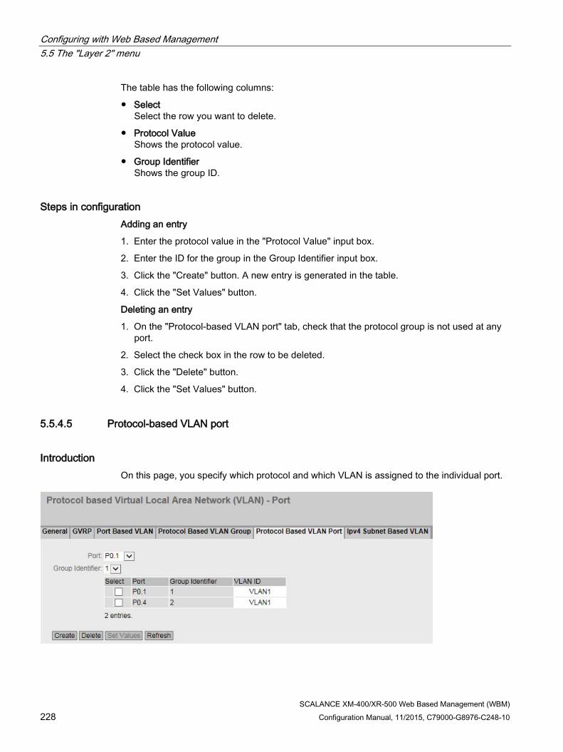
Configuring with Web Based Management 5.5 The "Layer 2" menu
SCALANCE XM-400/XR-500 Web Based Management (WBM) 228 Configuration Manual, 11/2015, C79000-G8976-C248-10
The table has the following columns:
● Select Select the row you want to delete.
● Protocol Value Shows the protocol value.
● Group Identifier Shows the group ID.
Steps in configuration Adding an entry
1. Enter the protocol value in the "Protocol Value" input box.
2. Enter the ID for the group in the Group Identifier input box.
3. Click the "Create" button. A new entry is generated in the table.
4. Click the "Set Values" button.
Deleting an entry
1. On the "Protocol-based VLAN port" tab, check that the protocol group is not used at any port.
2. Select the check box in the row to be deleted.
3. Click the "Delete" button.
4. Click the "Set Values" button.
5.5.4.5 Protocol-based VLAN port
Introduction On this page, you specify which protocol and which VLAN is assigned to the individual port.

Configuring with Web Based Management 5.5 The "Layer 2" menu
SCALANCE XM-400/XR-500 Web Based Management (WBM) Configuration Manual, 11/2015, C79000-G8976-C248-10 229
Description of the displayed boxes The page contains the following boxes:
● Port Select the port in the drop-down list. All available ports and the link aggregations can be selected.
● Group Identifier Select the group ID in the drop-down list. You specify the ID the WBM page "Protocol Based VLAN Group".
The table has the following columns:
● Select Select the row you want to delete.
● Port All available ports and the link aggregations are shown.
● Group Identifier Shows the group ID assigned to the port.
● VLAN ID From the drop-down list, select the VLAN ID you want to assign to the port.
Steps in configuration 1. Select the port from the "Port" drop-down list.
2. Select the group ID from the "Group Identifier" drop-down list.
3. Click the "Create" button. A new entry is generated in the table.
4. Specify the VLAN ID in " VLAN ID".
5. Click the "Set Values" button.

Configuring with Web Based Management 5.5 The "Layer 2" menu
SCALANCE XM-400/XR-500 Web Based Management (WBM) 230 Configuration Manual, 11/2015, C79000-G8976-C248-10
5.5.4.6 IPv4 subnet-based VLAN
Introduction On this page, you specify which VLAN ID is assigned to the subnet.
Description of the displayed boxes The page contains the following boxes:
● Subnet-based VLAN Enable or disable the IPv4 subnet-based VLAN assignment.
● Port Select the port in the drop-down list. All available ports and the link aggregations can be selected.
● Subnet Address
Enter the IPv4 address of the subnet. Example: 192.168.10.0 for the network 192.168.10.x with nodes 192.168.10.1 to 192.168.10.254.
● Subnet Mask Enter the subnet mask.
The table has the following columns:
● Select Select the row you want to delete.
● Port All available ports and the link aggregations are shown.
● Subnet Address
Shows the IPv4 address of the port.

Configuring with Web Based Management 5.5 The "Layer 2" menu
SCALANCE XM-400/XR-500 Web Based Management (WBM) Configuration Manual, 11/2015, C79000-G8976-C248-10 231
● Subnet Mask
Shows the subnet assigned to the port.
● VLAN ID Select the VLAN ID you want to assign to the port or the subnet.
Steps in configuration 1. Select a port from the "Port" drop-down list.
2. In "Subnet", enter the subnet mask.
3. Click the "Create" button. A new entry is generated in the table.
4. Select the VLAN ID from the "VLAN ID" drop down list.
5. Click the "Set Values" button.
5.5.5 Mirroring
Note
It cannot be guaranteed when mirroring the data traffic that all packets are mirrored.
Mirroring The device provides the option of simultaneously channeling incoming or outgoing data streams via other interfaces for analysis or monitoring. This has no effect on the monitored data streams. This procedure is known as mirroring. In this menu section, you enable or disable mirroring and set the parameters.
Mirroring ports Mirroring a port means that the data traffic at a port (mirrored port) of the IE switch is copied to another port (monitor port). You can mirror one or more ports to a monitor port.
If a protocol analyzer is connected to the monitor port, the data traffic at the mirrored port can be recorded without interrupting the connection. This means that the data traffic can be investigated without being affected. This is possible only if a free port is available on the device as the monitor port.

Configuring with Web Based Management 5.5 The "Layer 2" menu
SCALANCE XM-400/XR-500 Web Based Management (WBM) 232 Configuration Manual, 11/2015, C79000-G8976-C248-10
Function Extender BUS ANALYZER Agent XM-400 You can use the Function Extender BUS ANALYZER Agent XM-400 with the basic devices SCALANCE XM-400 as of firmware version 5.1.
The function extender BUS ANALYZER Agent XM-400 is a modular network component with 4 internal monitor ports for port mirroring. Ports of the basic device can be mirrored on the internal ports of the function extender BUS ANALYZER Agent XM-400 and their data traffic recorded. You do not need to reserve any ports of the basic device or a port extender for this.
● The mirrored data traffic is available on the management port (M1) of the BUS ANALYZER Agent XM-400.
● To record the mirrored data traffic, the software BUS ANALYZER SCOPE is used.
5.5.5.1 General
Mirroring in general On this page, you can enable or disable the "Mirroring" function and make the basic settings.
Note
Mirroring a port does not work beyond switch core boundaries. Refer to the operating instructions of the device.
Note
You need to disable port mirroring if you want to connect a normal end device to the monitor port. This does not apply to the function extender BUS ANALYZER Agent XM-400.
Note the data rate If the maximum data rate of the mirrored port is higher than that of the monitor port, data may be lost and the monitor port no longer reflects the data traffic at the mirrored port. Several ports can be mirrored to one monitor port at the same time.
Several source ports from the same VLAN If in a VLAN you select more than one source port for the port-based egress mirroring, unknown unicast and multicast frames as well as broadcast frames are forwarded only once to the destination port. With several sessions, the corresponding frames are only visible in one session, they are only mirrored to one destination port.

Configuring with Web Based Management 5.5 The "Layer 2" menu
SCALANCE XM-400/XR-500 Web Based Management (WBM) Configuration Manual, 11/2015, C79000-G8976-C248-10 233
RSPAN With RSPAN (Remote Switched Port Analyzer) you can forward the data traffic of a mirroring session to the monitor port via a VLAN. On the RSPAN VLAN, the mirrored data traffic is not disturbed by other data.
Settings

Configuring with Web Based Management 5.5 The "Layer 2" menu
SCALANCE XM-400/XR-500 Web Based Management (WBM) 234 Configuration Manual, 11/2015, C79000-G8976-C248-10
The page contains the following boxes:
● Mirroring
Click this check box to enable or disable mirroring.
● Monitor Barrier
Click this check box to enable or disable Monitor Barrier
Note Effects of monitor barrier
If you enable this option, management of the switch via the monitor port is no longer reachable. The following port-specific functions are changed: • DCP forwarding is turned off • LLDP is turned off • Unicast, multicast and broadcast blocking is turned on
The previous statuses of these functions are no longer restored after disabling monitor barrier again. They are reset to the default values and may need to be reconfigured.
You can reconfigure these functions manually even if monitor barrier is turned on. The data traffic on the monitor port is also allowed again. If you do not require this, make sure that only the data traffic you want to monitor is forwarded to the interface.
If mirroring is disabled, the listed port-specific functions are reset to the default values. This reset takes place regardless of whether the functions were configured manually or automatically by enabling "Monitor Barrier".
Note
Function Extender BUS ANALYZER Agent XM-400
If the destination port is a port of the function extender BUS ANALYZER Agent XM-400 the monitor barrier option is always activated. It is activated regardless of whether the check box was disabled or enabled.
● RSPAN VLAN ID
● Select a VLAN.
The table for the basic settings contains the following boxes:
● Select
Select the row you want to delete.
● Session ID
The Session ID is assigned automatically when a new entry is created.

Configuring with Web Based Management 5.5 The "Layer 2" menu
SCALANCE XM-400/XR-500 Web Based Management (WBM) Configuration Manual, 11/2015, C79000-G8976-C248-10 235
● Session Type
Select the required entry from the drop-down list:
– -
None
– Port-based
Port-based mirroring
– VLAN
VLAN-based mirroring
– MAC ACL
Mirroring of the MAC Access Control List
– IP ACL
Mirroring of the IP Access Control List
Note
If you have created a session of the type "VLAN" "MAC ACL" or "IP ACL", you cannot create any further sessions. You can create up to 7 sessions of the type "Port-based".
Note
If you change the "Session Type" of an existing session, all previous configurations of this session are lost.
● Status
Shows whether or not mirroring is enabled.
● Dest. Port
From the drop-down list, select the destination port to which data will be mirrored in this session.
Note
Function Extender BUS ANALYZER Agent XM-400
If you connect a function extender BUS ANALYZER Agent XM-400 with a SCALANCE XM-400 basic device as of firmware version 5.1, you can select up to four ports of the function extender BUS ANALYZER Agent XM-400 as destination ports. Function extender BUS ANALYZER Agent XM-400 supports port-based, VLAN-based, MAC ACL-based and IP ACL-based mirroring.
● RSPAN
Enable or disable RSPAN for a session.
Configuring with Web Based Management 5.5 The "Layer 2" menu
SCALANCE XM-400/XR-500 Web Based Management (WBM) 236 Configuration Manual, 11/2015, C79000-G8976-C248-10
Procedure Creating a mirroring session
1. Activate mirroring.
2. Click the "Create" button to create a further entry in the table.
The session ID is assigned automatically. Depending on the session type selected, you can create one or more mirroring sessions.
3. Select a "Session Type".
4. Click the "Set Values" button.
5. Select a destination port.
6. Click the "Set Values" button to save and activate the selected settings.
7. Change to the following tabs to make further detailed settings for the relevant session ID.
Deleting a mirroring session
1. Click the check box in the first column to select the row.
2. Click the "Delete" button to delete the selected rows.
Mirroring with RSPAN
1. Create a VLAN for the RSPAN data traffic on all devices involved.
Note
You can only create one RSPAN VLAN.
2. Create a mirroring session.
3. Select the "RSPAN VLAN ID.
4. Enable the check box in the "RSPAN" column.
5. Click the "Set Values" button to save the selected settings.

Configuring with Web Based Management 5.5 The "Layer 2" menu
SCALANCE XM-400/XR-500 Web Based Management (WBM) Configuration Manual, 11/2015, C79000-G8976-C248-10 237
5.5.5.2 Port
Mirroring ports You can only configure the settings on this page if you have already generated a session ID with the session type "Port-based" on the "General" tab.
Description of the displayed boxes The page contains the following drop down list:
● Session ID Select the session you want to monitor. Up to 7 parallel sessions are possible and their ports must not overlap.
The table has the following columns:
● Port Shows the available ports. The port is made up of the module number and the port number, for example port 0.1 is module 0, port 1.
● Ingress Mirroring Enable or disable listening in on incoming packets at the required port.
● Egress Mirroring Enable or disable listening in on outgoing packets at the required port.

Configuring with Web Based Management 5.5 The "Layer 2" menu
SCALANCE XM-400/XR-500 Web Based Management (WBM) 238 Configuration Manual, 11/2015, C79000-G8976-C248-10
Steps in configuration 1. In the "Session ID" drop-down list, select the session you created earlier on the "General"
tab.
2. In the table, click the check box of the row after the port to be mirrored. Select whether you want to monitor incoming or outgoing packets. To monitor the entire data traffic of the port, select both check boxes.
3. Click the "Set Values" button.
5.5.5.3 VLAN
VLAN sources of the port mirroring You can only configure the settings on this page if you have already generated a session ID with the session type "VLAN" on the "General" tab.
On this page, you specify the VLAN whose incoming data traffic will be mirrored to the monitor port.
Description of the displayed boxes The page contains the following boxes: ● Session ID
Select the session you want to monitor. Only one session is possible. ● VLAN ID
Enter the VLAN ID in the "VLAN ID" input box. Range of values: 1 ... 4094
The table "Ingress Mirroring " has the following columns: ● Select
Select the row you want to delete.
● VLAN ID Shows the VLAN ID for which the incoming frames are mirrored. The VLAN ID (a number between 1 and 4094) can only be assigned once when creating a new data record and can then no longer be changed. To make a change, the entire data record must be deleted and created again. Up to 257 VLANs can be defined.

Configuring with Web Based Management 5.5 The "Layer 2" menu
SCALANCE XM-400/XR-500 Web Based Management (WBM) Configuration Manual, 11/2015, C79000-G8976-C248-10 239
5.5.5.4 MAC Flow
ACL filter for port mirroring You can only configure the settings on this page if you have already generated a session ID with the session type " "MAC ACL" on the "General" tab.
The ACL filter decides which data is available at the monitor port.
Description of the displayed boxes ● Session ID
Select the session you want to monitor. Only one session is possible.
● ACL Filter Number Shows the number of the ACL filter.
● Ingress Mirroring Shows whether incoming packets are mirrored.
Note
Rules
The selected rule only becomes active when you specify with which ACL rules the incoming packets will be filtered for at least one interface. You configure the settings in "Security > MAC ACL > Ingress Rules".
● Source MAC Shows the MAC address of the sender.
● Dest. MAC Shows the MAC address of the recipient.
● Ingress Interfaces Shows all interfaces to which this rule applies. The ACL filter decides which incoming data streams are mirrored on the monitor port (destination port).
● Egress Interfaces Shows all interfaces to which this rule applies.

Configuring with Web Based Management 5.5 The "Layer 2" menu
SCALANCE XM-400/XR-500 Web Based Management (WBM) 240 Configuration Manual, 11/2015, C79000-G8976-C248-10
5.5.5.5 IP Flow
ACL filter for port mirroring You can only configure the settings on this page if you have already generated a session ID with the session type " "IP ACL" on the "General" tab.
The ACL filter decides which data is available at the monitor port.
Description of the displayed boxes ● Session ID
Select the session you want to monitor. Only one session is possible.
● ACL Filter Number Shows the number of the ACL filter.
● Ingress Mirroring Shows whether incoming packets are mirrored.
Note
Rules
The selected rule only becomes active when you specify with which ACL rules the incoming packets will be filtered for at least one interface. You configure the settings in "Security > IP ACL > Ingress Rules".
● Source IP Shows the IPv4 address of the destination device.
● Source Subnet Mask Shows the subnet mask of the sender.
● Dest. IP Shows the IPv4 address of the recipient.
● Dest. Subnet Mask Shows the subnet mask of the recipient.

Configuring with Web Based Management 5.5 The "Layer 2" menu
SCALANCE XM-400/XR-500 Web Based Management (WBM) Configuration Manual, 11/2015, C79000-G8976-C248-10 241
● Ingress Interfaces Shows all interfaces to which this rule applies. The ACL filter decides which incoming data streams are mirrored on the monitor port (destination port).
● Egress Interfaces Shows all interfaces to which this rule applies. The ACL filter decides which outgoing data streams are mirrored on the monitor port (destination port).
5.5.6 Dynamic MAC Aging
Protocol settings and switch functionality The device automatically learns the source addresses of the connected nodes. This information is used to forward data frames to the nodes specifically involved. This reduces the network load for the other nodes. If a device does not receive a frame whose source address matches a learnt address within a certain time, it deletes the learnt address. This mechanism is known as "Aging". Aging prevents frames being forwarded incorrectly, for example when an end device (for example a programming device) is connected to a different switch port. If the check box is not enabled, a device does not delete learnt addresses automatically.
Description of the displayed boxes The page contains the following boxes:
● Dynamic MAC Aging Enable or disable the function for automatic aging of learned MAC addresses:
● Aging Time [s] Enter the time in seconds. After this time, a learned address is deleted if the device does not receive any further frames from this sender address. The range of values is from 10 seconds to 630 seconds
Steps in configuration 1. Select the "Dynamic MAC Aging" check box.
2. Enter the time in seconds in the "Aging Time [s]" input box.
3. Click the "Set Values" button.

Configuring with Web Based Management 5.5 The "Layer 2" menu
SCALANCE XM-400/XR-500 Web Based Management (WBM) 242 Configuration Manual, 11/2015, C79000-G8976-C248-10
5.5.7 Ring redundancy
5.5.7.1 Ring
Rules for ring redundancy Factory settings
● The factory setting defines MSTP as the redundancy method.
● With SCALANCE XM-400, the factory setting defines ports P1.1 and P1.2 as ring ports.
● With SCALANCE XM-500, the factory setting defines ports P0.1 and P0.2 as ring ports.
Ring ports
The predefined ring ports of SCALANCE XR-500 are 10 Gbps ports.
If a 1000 Mbps SFP transceiver is plugged into one of the 10 Gbps ring ports, you cannot enable ring redundancy.
Remove the 1000 Mbps SFP transceiver.
Enabling redundancy
You can enable ring redundancy as follows:
● using the WBM
● using the CLI
● using the SELECT/SET button
● using a PNIO configuration download
Configuration of ring redundancy

Configuring with Web Based Management 5.5 The "Layer 2" menu
SCALANCE XM-400/XR-500 Web Based Management (WBM) Configuration Manual, 11/2015, C79000-G8976-C248-10 243
● Ring Redundancy If you enable the "Ring Redundancy" check box, you turn ring redundancy on. The ring ports set on this page are used.
● Ring redundancy mode
Here, you set the mode of the ring redundancy.
The following modes are available:
– Automatic Redundancy Detection
Select this setting to create an automatic configuration of the redundancy mode.
In the "Automatic Redundancy Detection" mode, the device automatically detects whether or not there is a device with the "HRP Manager" role in the ring. If there is, the device adopts the role "HRP" client. If no HRP manager is found, all devices with the "Automatic Redundancy Detection" or "MRP Auto Manager" setting negotiate among themselves to establish which device adopts the role of "MRP Manager". The device with the lowest MAC address will always become "MRP Manager". The other devices automatically set themselves to "MRP Client" mode.
– MRP Auto-Manager
Automatic media redundancy manager
– MRP Client
Media redundancy client
– HRP Client
High Speed Redundancy Protocol client
– HRP Manager
High Speed Redundancy Protocol manager
● Ring ports
Here, you set the ports to be used as ring ports in ring redundancy.
The ring port you select in the left-hand drop-down menu is the "Isolated Port" in HRP.

Configuring with Web Based Management 5.5 The "Layer 2" menu
SCALANCE XM-400/XR-500 Web Based Management (WBM) 244 Configuration Manual, 11/2015, C79000-G8976-C248-10
● Observer
Enable or disable the observer. The "Observer" function is only available in HRP rings.
The ring port selected in the left-hand drop-down menu is connected to the "isolated port" of an HRP manager.
The observer monitors malfunctions of the redundancy manager or incorrect configurations of an HRP ring.
If the observer is enabled, it can interrupt the connected ring if errors are detected. To do this, the observer switches a ring port to the "blocking" status. When the error is resolved, the observer enables the port again.
● Restart Observer
If numerous errors occur in quick succession, the observer no longer enables its port automatically. The ring port remains permanently in the "blocking" status. This is signaled by the error LED and a message text.
After the errors have been eliminated, you can enable the port again using the "Restart Observer" button.
Restoring factory settings If you have restored the factory defaults, ring redundancy is disabled and the default ports are used as the ring ports. This can lead to circulating frames and failure of the data traffic if other settings were used in a previous configuration.
Changing over the status of the ring ports with the redundancy manager If you configure a redundancy manager, set the status of the ring ports. The first ring port changes to the "blocking" status and the second ring port to the "forwarding" status. As long as ring redundancy is enabled, you cannot change the status of these ring ports.
Note
Make sure that you first open the ring so that there are no circulating frames.
Changing ring ports You can change the ring ports without needing to open the ring.
To change the ring ports, follow the steps below:
1. Change to the page "Layer 2 > Spanning Tree > CIST Port".
2. Disable the ports in the spanning tree you want to configure as ring ports.
3. Change to the page "Layer 2 > Ring Redundancy > Ring".
4. Select the new ring ports.
5. Change the cable connections.
6. Change to the page "Layer 2 > Spanning Tree > CIST Port".
7. Enable the ports in the spanning tree that are no longer ring ports.

Configuring with Web Based Management 5.5 The "Layer 2" menu
SCALANCE XM-400/XR-500 Web Based Management (WBM) Configuration Manual, 11/2015, C79000-G8976-C248-10 245
5.5.7.2 Standby
Redundant linking of rings Standby redundancy allows the redundant linking of HRP rings.
To establish a standby connection, configure two neighboring devices within a ring as standby master or standby slave. The standby master and the standby slave must be connected via parallel cables to two devices in another ring.
In problem-free operation, messages are exchanged between the two rings via the master. If the master's line is disturbed, the slave takes over the forwarding of messages between the two rings.
Enable standby redundancy for both standby partners and select the ports via which the device is connected to the rings you want to link to.
For the "Standby Connection Name", a name unique within the ring must be assigned for both partners. This identifies the two devices as standby partners that belong together.
Note
To be able to use the function, HRP must be activated.
The standby manager always requires an activated HRP client.
Note Standby master coupling with an optical 100 Mbps connection
While the coupling partner of a standby master with an optical 100 Mbps connection starts up again, physically disconnect the connection between the standby master and its coupling partner.

Configuring with Web Based Management 5.5 The "Layer 2" menu
SCALANCE XM-400/XR-500 Web Based Management (WBM) 246 Configuration Manual, 11/2015, C79000-G8976-C248-10
Description of the displayed boxes ● Standby
Click the check box to enable or disable the function.
● Standby Port Select the port to be standby port. The link to the other ring is via the standby port.
Note
Standby ports in the spanning tree
Before you enable the port as the standby port, you need to disable the port in the spanning tree. 1. Change to the page "Layer 2 > Spanning Tree > CIST Port". 2. Disable the ports in the spanning tree you want to configure as standby ports.
The standby port is involved in the redirection of data traffic. In there are no problems, only the standby port of the master is enabled and handles the data traffic into the connected HRP ring or HRP bus.
If the master or the Ethernet connection (link) of one of the standby ports of the master fails, the standby port of the master will be disabled and the standby port of the slave enabled. As a result, a functioning Ethernet connection to the connected network segment (HRP ring or HRP linear bus) is restored.
● Standby Connection Name This name defines the master/slave device pair. Both devices must be located in the same ring.
Here, enter the name for the standby connection. This must be identical to the name entered on the standby partner. You can select any name to suit your purposes, however, you can only use the name for one pair of devices in the entire network.

Configuring with Web Based Management 5.5 The "Layer 2" menu
SCALANCE XM-400/XR-500 Web Based Management (WBM) Configuration Manual, 11/2015, C79000-G8976-C248-10 247
● Force device to Standby Master If you select this check box, the device is configured as a standby master regardless of its MAC address.
– If this check box is not selected for either of the devices for which the standby master is enabled, then assuming that no error has occurred, the device with the higher MAC address adopts the role of standby master.
– If the option is selected for both devices or if the "Force device to Standby Master" property is supported by only one device, the standby master is also selected based on the MAC address.
This type of assignment is important in particular when a device is replaced. Depending on the MAC addresses, the previous device with the slave function can take over the role of the standby master.
Note
If two devices are linked by the standby function, the "Standby" function must be enabled on both devices.
● Wait for Standby Partner
– Enabled
A standby connection is enabled only after the standby master and the standby slave as well as their standby partners have established a connection. This ensures that the redundant connection is really available before communication via a standby connection is enabled.
– Disabled
A standby connection is enabled even if the standby master has not yet established a connection to the standby slave.
This can lead to circulating frames and failure of the data traffic if another standby connection has already been enabled. Multiple standby connections can, for example, result due to configuration errors if different standby connection names were assigned to the standby master and standby slave.

Configuring with Web Based Management 5.5 The "Layer 2" menu
SCALANCE XM-400/XR-500 Web Based Management (WBM) 248 Configuration Manual, 11/2015, C79000-G8976-C248-10
5.5.8 Spanning tree
5.5.8.1 General
General settings of MSTP This is the basic page for spanning tree. Select the compatibility mode from the drop-down list. As default, Multiple Spanning Tree is enabled.
On the configuration pages of these functions, you can make further settings.
Depending on the compatibility mode, you can configure the corresponding function on the relevant configuration page.
Description of the displayed boxes The page contains the following boxes:
● Spanning Tree Enable or disable Spanning Tree.
● Protocol Compatibility Select the compatibility mode of MSTP. For example if you select RSTP, MSTP behaves like RSTP.
The following settings are available:
– STP
– RSTP
– MSTP
Steps in configuration 1. Select the "MSTP" check box.
2. From the "Protocol Compatibility" drop-down list, select the type of compatibility.
3. Click the "Set Values" button.

Configuring with Web Based Management 5.5 The "Layer 2" menu
SCALANCE XM-400/XR-500 Web Based Management (WBM) Configuration Manual, 11/2015, C79000-G8976-C248-10 249
5.5.8.2 CIST General
MSTP-CIST configuration The page consists of the following parts.
● The left-hand side of the page shows the configuration of the device.
● The central part shows the configuration of the root bridge that can be derived from the spanning tree frames received by an device.
● The right-hand side shows the configuration of the regional root bridge that can be derived from the MSTP frames received by an device. The displayed data is only visible if you have enabled "Spanning Tree"on the "General" page and if "MSTP" is set for "Protocol Compatibility". This also applies to the "Bridge Max Hop Count" parameter. If the device is a root bridge, the information on the left and right matches.
Description of the displayed boxes The page contains the following boxes:
● Bridge Priority / Root Priority The Bridge Priority decides which device becomes the Root Bridge. The Bridge with the highest priority becomes the Root Bridge. The lower the value, the higher the priority. If several devices in a network have the same priority, the device whose MAC address has the lowest numeric value will become the root bridge. Both parameters, bridge priority and MAC address together form the Bridge identifier. Since the root bridge manages all path changes, it should be located as centrally as possible due to the delay of the frames. The value for the bridge priority is a whole multiple of 4096 with a range of values from 0 through 61440.
● Bridge Address / Root Address The bridge address shows the MAC address of the device and the root address shows the MAC address of the root bridge.

Configuring with Web Based Management 5.5 The "Layer 2" menu
SCALANCE XM-400/XR-500 Web Based Management (WBM) 250 Configuration Manual, 11/2015, C79000-G8976-C248-10
● Root port Shows the port via which the switch communicates with the root bridge.
● Root Cost The path costs from this device to the root bridge.
● Topology Changes / Last Topology Change The entry for the device shows the number of reconfiguration actions due to the spanning tree mechanism since the last startup. For the root bridge, the time since the last reconfiguration is displayed as follows:
– Seconds: sec unit after the number
– Minutes: min unit after the number
– Hour: hr unit after the number
● Bridge hello time [s] / Root hello time [s] Each bridge sends configuration frames (BPDUs) regularly. The interval between two such frames is the Hello time. The default for this parameter is 2 seconds.
● Bridge forward delay[s] / Root Forward Delay [s] New configuration data is not used immediately by a bridge but only after the period specified in the parameter. This ensures that operation is only started with the new topology after all the bridges have the required information. The default for this parameter is 15 seconds.
● Bridge Max Age / Root Max Age When the max age timer elapses the received BPDU is discarded to be accepted as valid by the switch. The default value is 20s.
● Regional root priority For a description, see Bridge Priority / Root Priority
● Regional root address The MAC address of the device.
● Regional Root Costs The path costs from this device to the root bridge.
● Bridge Max Hop Count This parameter specifies how many MSTP nodes a BPDU may pass through. If an MSTP BPDU is received and has a hop count that exceeds the value configured here, it is discarded. The default for this parameter is 20.
● Reset Counters
Click this button to reset the counters on this page.
● Region Name Enter the name of the MSTP region to which this device belongs. As default, the MAC address of the device is entered here. This value must be the same on all devices that belong to the same MSTP region.
● Region Version Enter the version number of the MSTP region in which the device is located. This value must be the same on all devices that belong to the same MSTP region

Configuring with Web Based Management 5.5 The "Layer 2" menu
SCALANCE XM-400/XR-500 Web Based Management (WBM) Configuration Manual, 11/2015, C79000-G8976-C248-10 251
Steps in configuration 1. Enter the data required for the configuration in the input boxes.
2. Click the "Set Values" button.
5.5.8.3 CIST Port
MSTP-CIST port configuration When the page is called, the table displays the current status of the configuration of the port parameters.
To configure them, click the relevant cells in the port table.

Configuring with Web Based Management 5.5 The "Layer 2" menu
SCALANCE XM-400/XR-500 Web Based Management (WBM) 252 Configuration Manual, 11/2015, C79000-G8976-C248-10
Description of the displayed boxes Table 1 has the following columns:
● 1st column Shows that the settings are valid for all ports of table 2.
● Spanning Tree Status Select the setting from the drop-down list. You have the following setting options:
– enabled Port is integrated in the spanning tree.
– disabled Port is not integrated in the spanning tree.
– No Change Table 2 remains unchanged.
● Copy to Table If you click the button, the setting is adopted for all ports of table 2.
Table 2 has the following columns:
● Port Shows the available ports. The port is made up of the module number and the port number, for example port 0.1 is module 0, port 1.
● Spanning Tree Status Specify whether or not the port is integrated in the spanning tree.
Note
If you disable the "Spanning Tree Status" option for a port, this may cause the formation of loops. The topology must be kept in mind.
● Priority Enter the priority of the port. The priority is only evaluated when the path costs are the same. The value must be divisible by 16. If the value that cannot be divided by 16, the value is automatically adapted. Range of values: 0 - 240. The default is 128.
● Cost Calc. Enter the path cost calculation. If you enter the value "0", the automatically calculated value is displayed in the "Path Cost" box.

Configuring with Web Based Management 5.5 The "Layer 2" menu
SCALANCE XM-400/XR-500 Web Based Management (WBM) Configuration Manual, 11/2015, C79000-G8976-C248-10 253
● Path Cost This parameter is used to calculate the path that will be selected. The path with the lowest value is selected as the path. If several ports of a device have the same value for the path costs, the port with the lowest port number is selected. If the value in the "Cost Calc" field is "0", the automatically calculated value is displayed. Otherwise, the value of the "Cost Calc" field is displayed. The calculation of the path costs is largely based on the transmission speed. The higher the achievable transmission speed is, the lower the value of the path costs.
Typical values for path costs with rapid spanning tree:
– 10,000 Mbps = 2,000
– 1000 Mbps = 20,000
– 100 Mbps = 200,000
– 10 Mbps = 2,000,000
The values can, however, also be set individually.
● Status Displays the current status of the port. The values are only displayed and cannot be configured. The "Status" parameter depends on the configured protocol. The following is possible for status:
– Disabled The port only receives and is not involved in STP, MSTP and RSTP.
– Discarding In the "Discarding" mode, BPDU frames are received. Other incoming or outgoing frames are discarded.
– Listening In this status, BPDUs are both received and sent. The port is involved in the spanning tree algorithm.
– Learning Stage prior to the forwarding status, the port is actively learning the topology (in other words, the node addresses).
– Forwarding Following the reconfiguration time, the port is active in the network; it receives and forwards data frames.
● Fwd. Trans Specifies the number of changes from the "Discarding" status to the "Forwarding" status.
● Edge Type Specify the type of edge port. You have the following options:
– "-" Edge port is disabled. The port is treated as a "no EdgePort".
– Admin Select this option when there is always an end device on this port. Otherwise a reconfiguration of the network will be triggered each time a connection is changed.
– Auto Select this option if you want a connected end device to be detected automatically at

Configuring with Web Based Management 5.5 The "Layer 2" menu
SCALANCE XM-400/XR-500 Web Based Management (WBM) 254 Configuration Manual, 11/2015, C79000-G8976-C248-10
this port. When the connection is established the first time, the port is treated as a "no Edge Port".
– Admin/Auto Select these options if you operate a combination of both on this port. When the connection is established the first time, the port is treated as an Edge Port.
● Edge Shows the status of the port.
– Enabled An end device is connected to this port.
– Disabled There is a Spanning Tree or Rapid Spanning Tree device at this port.
With an end device, a switch can change over the port faster without taking into account spanning tree frames. If a spanning tree frame is received despite this setting, the port automatically changes to the "Disabled" setting for switches.
● P.t.P. Type Select the required option from the drop-down list. The selection depends on the port that is set.
– "-" Point to point is calculated automatically. If the port is set to half duplex, a point-to-point link is not assumed.
– P.t.P. Even with half duplex, a point-to-point link is assumed.
– Shared Media Even with a full duplex connection, a point-to-point link is not assumed.
Note
Point-to-point connection means a direct connection between two devices. A shared media connection is, for example, a connection to a hub.
● Hello Time Enter the interval after which the bridge sends configuration BPDUs. As default, 2 seconds is set. Range of values: 1-2 seconds
Note
The port-specific setting of the Hello time is only possible in MSTP compatible mode.
Steps in configuration 1. In the input cells of the table row, enter the values of the port you are configuring.
2. From the drop-down lists of the cells of the table row, select the values of the port you are configuring.
3. Click the "Set Values" button.

Configuring with Web Based Management 5.5 The "Layer 2" menu
SCALANCE XM-400/XR-500 Web Based Management (WBM) Configuration Manual, 11/2015, C79000-G8976-C248-10 255
5.5.8.4 MST General
Multiple Spanning Tree configuration With MSTP, in addition to RSTP, several VLANs can be managed in a LAN with separate RSTP trees.
Description The page contains the following box:
● MSTP Instance ID Enter the number of the MSTP instance. Permitted values: 1 - 64 You can define up to 16 MSTP instances.
The table has the following columns:
● Select Select the row you want to delete.
● MSTP instance ID Shows the number of the MSTP instance.
● Root Address Shows the MAC address of the root bridge
● Root Priority Shows the priority of the root bridge.
● Bridge Priority Enter the bridge priority in this box. The value for the bridge priority is a whole multiple of 4096 with a range of values from 0 to 61440.
● VLAN ID Enter the VLAN ID. Here, you can also specify ranges with Start ID, "-", End ID. Several ranges or IDs are separated by ",". Permitted values: 1- 4094

Configuring with Web Based Management 5.5 The "Layer 2" menu
SCALANCE XM-400/XR-500 Web Based Management (WBM) 256 Configuration Manual, 11/2015, C79000-G8976-C248-10
Procedure Creating a new entry
1. Enter the number of the MSTP instance in the "MSTP Instance ID" box.
2. Click the "Create" button.
3. Enter the identifier of the virtual LAN in the "VLAN ID" input box.
4. Enter the priority of the bridge in the "Bridge Priority" box.
5. Click the "Set Values" button.
Deleting entries
1. Use the check box at the beginning of the relevant row to select the entries to be deleted.
2. Click the "Delete" button to delete the selected entries from memory. The entries are deleted from the memory of the device and the display on this page is updated.
5.5.8.5 MST Port
Configuration of the Multiple Spanning Tree port parameters On this page, you set the parameters for the ports of the configured multiple spanning tree instances.
Description of the displayed boxes The page contains the following box:
● MSTP Instance ID In the drop-down list, select the ID of the MSTP instance.

Configuring with Web Based Management 5.5 The "Layer 2" menu
SCALANCE XM-400/XR-500 Web Based Management (WBM) Configuration Manual, 11/2015, C79000-G8976-C248-10 257
Table 1 has the following columns:
● 1st column Shows that the settings are valid for all ports.
● MSTP Status Select the setting from the drop-down list. You have the following setting options:
– enabled
– disabled
– No Change: Table 2 remains unchanged.
● Copy to Table If you click the button, the setting is adopted for all ports of table 2.
Table 2 has the following columns:
● Port Shows all available ports and link aggregations.
● MSTP Instance ID ID of the MSTP instance.
● MSTP Status Click the check box to enable or disable this option.
● Priority Enter the priority of the port. The priority is only evaluated when the path costs are the same. The value must be divisible by 16. If the value that cannot be divided by 16, the value is automatically adapted. Range of values: 0 - 240. The default is 128.
● Cost Calc. Enter the path cost calculation in the input box. If you enter the value "0" here, the automatically calculated value is displayed in the next box "Path Cost".
● Path cost The path costs from this port to the root bridge. The path with the lowest value is selected as the path. If several ports of a device have the same value, the port with the lowest port number is selected. If the value in the "Cost Calc" field is "0", the automatically calculated value is displayed. Otherwise, the value of the "Cost Calc" field is displayed. The calculation of the path costs is largely based on the transmission speed. The higher the achievable transmission rate, the lower the value for the path costs will be. Typical values for rapid spanning tree are as follows:
– 1000 Mbps = 20,000
– 100 Mbps = 200,000
– 10 Mbps = 2,000,000
The values can, however, also be set individually.

Configuring with Web Based Management 5.5 The "Layer 2" menu
SCALANCE XM-400/XR-500 Web Based Management (WBM) 258 Configuration Manual, 11/2015, C79000-G8976-C248-10
● Status Displays the current status of the port. The values are only displayed and cannot be configured. The following is possible for status:
– Discarding The port exchanges MSTP information but is not involved in the data traffic.
– Blocked In the blocking mode, BPDU frames are received.
– Forwarding The port receives and sends data frames.
● Fwd. Trans. Specifies the number of status changes Discarding - Forwarding or Forwarding - Discarding for a port.
Steps in configuration 1. In the input cells of the table row, enter the values of the port you are configuring.
2. From the drop-down lists of the cells of the table row, select the values of the port you are configuring.
3. Click the "Set Values" button.

Configuring with Web Based Management 5.5 The "Layer 2" menu
SCALANCE XM-400/XR-500 Web Based Management (WBM) Configuration Manual, 11/2015, C79000-G8976-C248-10 259
5.5.8.6 Enhanced Passive Listening Compatibility
Enabling the function On this page, you can enable passive listening compatibility.
Description of the displayed boxes The page contains the following boxes:
● Enhanced Passive Listening Compatibility Enable or disable this function for the entire device.
● Setting
– enabled
Enable the function for all ports of the device
– disabled
Disable the function for all ports of the device
– No Change
No Change
● Copy to Table
Writes the setting made in "Setting" to the following table

Configuring with Web Based Management 5.5 The "Layer 2" menu
SCALANCE XM-400/XR-500 Web Based Management (WBM) 260 Configuration Manual, 11/2015, C79000-G8976-C248-10
Port-specific table: If the function is enabled for the entire device, enable or disable this function on individual ports.
● Port
Displays the port of the device.
● Setting
Enable or disable the function for this port
Steps in configuration Enable the function for the entire device
1. Enable or disable "Enhanced Passive Listening Compatibility"
2. Click the "Set Values" button.
For all ports of the device:
1. From the drop-down list, select whether the function should be enabled or disabled or adopted unchanged.
2. Click the "Copy to Table" button.
3. Click the "Set Values" button.
For individual ports of the device:
1. Click the check box after the required port in the port table to enable or disable the function.
2. Click the "Set Values" button.

Configuring with Web Based Management 5.5 The "Layer 2" menu
SCALANCE XM-400/XR-500 Web Based Management (WBM) Configuration Manual, 11/2015, C79000-G8976-C248-10 261
5.5.9 Loop Detection With the "Loop detection" function, you specify the ports for which loop detection will be activated. The ports involved send special test frames - the loop detection frames. If these frames are sent back to the device, there is a loop.
A "Local loop" involving this device means that the frames are received again at a different port of the same device. If the sent frames are received again at the same port, there is a "remote loop" involving other network components.
Note
A loop is an error in the network structure that needs to be eliminated. The loop detection can help to find the errors more quickly but does not eliminate them. The loop detection is not suitable for increasing network availability by deliberately including loops.
Note
Note that loop detection is only possible at ports that were not configured as ring ports or standby ports.
Description ● Loop Detection
Enable or disable the loop detection.
● VLAN Loop Detection Enable or disable the VLAN loop detection.

Configuring with Web Based Management 5.5 The "Layer 2" menu
SCALANCE XM-400/XR-500 Web Based Management (WBM) 262 Configuration Manual, 11/2015, C79000-G8976-C248-10
Table 1 contains the following columns:
● 1st column Shows that the settings are valid for all ports of table 2
● Threshold value / Remote reaction / Local reaction Make the required settings.
● Copy to table If you click the button, the setting is adopted for all ports of table 2
Table 2 contains the following columns:
● Port Shows the available ports.
● Setting Specify how the port handles loop detection frames. Select one of the following options from the drop-down list:
Note
Test frames create additional network load. We recommend that you only configure individual switches, for example at branch points of the ring, as "Sender" and the others as "Forwarder".
– Sender Loop detection frames are sent out and forwarded.
– Forwarder Loop detection frames from other devices are forwarded.
– blocked The forwarding of loop detection frames is blocked.
● Threshold By entering a number, specify the number of received loop detection frames as of which a loop is assumed.
● Remote reaction Specify how the port will react if a remote loop occurs. Select one of the two options from the drop-down list:
– no action: A loop has no effect on the port.
– disable: The port is blocked.
● Local reaction Specify how the port will react if a local loop occurs. Select one of the two options from the drop-down list:
– no action: A loop has no effect on the port.
– disable: The port is blocked
● Status This box shows whether loop detection is enabled or disabled for this port.
● Source Port Shows the receiving port of the loop detection frame that triggered the last reaction.
Configuring with Web Based Management 5.5 The "Layer 2" menu
SCALANCE XM-400/XR-500 Web Based Management (WBM) Configuration Manual, 11/2015, C79000-G8976-C248-10 263
● Source VLAN This box shows the VLAN ID of the loop detection frame that triggered the last reaction. This requires that the "VLAN Loop Detection" check box is selected.
● Reset After a loop in the network has been eliminated, click this button "Reset to reset the port again.
Changing the configured port status with loop detection The configuration of the port status can be changed with the "Loop Detection" function. If, for example, the administrator has disabled a port, the port can be enabled again after a device restart with "Loop Detection". The port status "link down" is not changed by "Loop Detection".
5.5.10 Link aggregation
Bundling network connections for redundancy and higher bandwidth Link aggregations according to IEEE 802.3ad allow several connections between neighboring devices to be bundled to achieve higher bandwidths and protection against failure.
Ports on both partner devices are included in link aggregations and the devices are then connected via these ports. To assign ports (in other words links) correctly to a partner device, the Link Aggregation Control Protocol (LACP) from the IEEE 802.3ad standard is used.
Up to 8 link aggregations can be defined. A maximum of 8 ports can be assigned to each link aggregation.
Note
When a port is assigned to a link aggregation but is not active (e.g. link down), the values displayed may differ from the values configured for the link aggregation.
If the port in the link aggregation becomes active, individual port configurations such as DCP forwarding are overwritten with the configured values of the link aggregation.

Configuring with Web Based Management 5.5 The "Layer 2" menu
SCALANCE XM-400/XR-500 Web Based Management (WBM) 264 Configuration Manual, 11/2015, C79000-G8976-C248-10
Display of the configured aggregation The menu displays all the configured link aggregations.
Description of the displayed boxes The table has the following columns:
● Select Select the row you want to delete.
● Port Shows the virtual port number of this link aggregation. This identifier is assigned internally by the firmware.
● Link Aggregation Name Shows the name of the link aggregation. This name can be specified by the user during configuration. The name is not absolutely necessary but can be useful to distinguish between the various link aggregations.
● MAC Address Shows the MAC address.
● Status Enable or disable link aggregation.
● MTU Specify the packet size.
● LACP
– On Enables the sending of LACP frames.
– Off Disables the sending of LACP frames.
● Frame Distribution Set the type of distribution of packets on the individual links of an aggregation.
– Destination&Source MAC The distribution is based on a combination of the destination and source MAC address.
– Destination&Source IP MAC The distribution is based on a combination of the destination and source IP and MAC address.

Configuring with Web Based Management 5.5 The "Layer 2" menu
SCALANCE XM-400/XR-500 Web Based Management (WBM) Configuration Manual, 11/2015, C79000-G8976-C248-10 265
● VLAN Mode Specify how the link aggregation is entered in a VLAN:
– Hybrid The link aggregation sends tagged and untagged frames. It is not automatically a member of a VLAN.
– Trunk The link aggregation only sends tagged frames and is automatically a member of all VLANs.
● Port Shows the ports that belong to this link aggregation. The following values can be selected from the drop-down list:
– "-" (disabled) Link aggregation is disabled.
– "a" (active) The port sends LACP frames and is only involved in the link aggregation when LACP frames are received.
– "p" (passive) The port is only involved in the link aggregation when LACP frames are received.
– o" (on) The port is involved in the link aggregation and does not send any LACP frames.
Note
Within a "link aggregation", only ports with the following configuration are possible: • all ports with "o" • all ports with "a" or "p".
Steps in configuration Basics prior to configuration
1. First, identify the ports you want to put together to form a link aggregation between the devices.
2. Configure the link aggregation on the devices.
3. Adopt the configuration for all devices.
4. Perform the last step, the cabling.
Note
If you cable aggregated links prior to configuration, it is possible that you will create loops in the network! The network involved may deteriorate badly due to this or complete disruption may occur.

Configuring with Web Based Management 5.5 The "Layer 2" menu
SCALANCE XM-400/XR-500 Web Based Management (WBM) 266 Configuration Manual, 11/2015, C79000-G8976-C248-10
Creating a new link aggregation
1. Click the "Create" button to create a new link aggregation.
This creates a new row.
2. Select the ports that will belong to this link aggregation.
3. Click the "Set Values" button.
Deleting an aggregation
1. Using the check box at the beginning of a row, select the link aggregation you want to delete.
2. Click the "Delete" button.
Changing an aggregation
1. In the overview, click on the relevant table entry to change the configuration of a created link aggregation.
2. Make all the changes.
3. Click the "Set Values" button.
5.5.11 DCP forwarding
Applications The DCP protocol is used by STEP 7 and the PST Tool for configuration and diagnostics. When shipped, DCP is enabled on all ports; in other words, DCP frames are forwarded at all ports. With this option, you can disable the sending of these frames for individual ports, for example to prevent individual parts of the network from being configured with the PST Tool or to divide the full network into smaller parts for configuration and diagnostics.
Note PNIO configuration
Since DCP is a PROFINET protocol, the configuration created here is only effective with the VLAN associated with the TIA interface.
All the ports of the device are displayed on this page. After each displayed port, there is a drop-down list for function selection.

Configuring with Web Based Management 5.5 The "Layer 2" menu
SCALANCE XM-400/XR-500 Web Based Management (WBM) Configuration Manual, 11/2015, C79000-G8976-C248-10 267
Description of the displayed values Table 1 has the following columns:
● 1st column Shows that the settings are valid for all ports of table 2.
● Setting Select the setting from the drop-down list. If "No Change is selected, the entry in table 2 remains unchanged.
● Copy to Table If you click the button, the setting is adopted for all ports of table 2.
Table 2 has the following columns:
● Port Shows the available ports. The port is made up of the module number and the port number, for example port 0.1 is module 0, port 1.
● Setting From the drop-down list, select whether the port should block or forward outgoing DCP frames. You have the following options available:
– Forward DCP frames are forwarded via this port.
– Block No outgoing DCP frames are forwarded via this port. It is nevertheless still possible to receive via this port.
Steps in configuration 1. From the options in the drop-down list in the row, select which ports should support
sending DCP frames.
2. Click the "Set Values" button.

Configuring with Web Based Management 5.5 The "Layer 2" menu
SCALANCE XM-400/XR-500 Web Based Management (WBM) 268 Configuration Manual, 11/2015, C79000-G8976-C248-10
5.5.12 LLDP
Identifying the network topology LLDP (Link Layer Discovery Protocol) is defined in the IEEE 802.AB standard.
LLDP is a method used to discover the network topology. Network components exchange information with their neighbor devices using LLDP.
Network components that support LLDP have an LLDP agent. The LLDP agent sends information about itself and receives information from connected devices at periodic intervals. The received information is stored in the MIB.
Applications PROFINET uses LLDP for topology diagnostics. In the default setting, LLDP is enabled for all ports; in other words, LLDP frames are sent and received on all ports. With this function, you have the option of enabling or disabling sending and/or receiving per port.
Description of the displayed boxes Table 1 has the following columns:
● 1st column Shows that the settings are valid for all ports.
● Setting Select the setting from the drop-down list. If "No Change" is selected, the entry in table 2 remains unchanged.
● Copy to Table If you click the button, the setting is adopted for all ports of table 2.

Configuring with Web Based Management 5.5 The "Layer 2" menu
SCALANCE XM-400/XR-500 Web Based Management (WBM) Configuration Manual, 11/2015, C79000-G8976-C248-10 269
Table 2 has the following columns:
● Port Shows the port.
● Settting From the drop-down list, select whether or not the port will send or receive LLDP frames. You have the following options available:
– Rx This port can only receive LLDP frames.
– Tx This port can only send LLDP frames.
– Rx & Tx This port can receive and send LLDP frames.
– "-" (disabled) This port can neither receive nor send LLDP frames.
Steps in configuration 1. From the drop-down list in the row of the port you want to configure, select the LLDP
functionality.
2. Click the "Set Values" button.
5.5.13 Fiber Monitoring Protocol
Requirements ● To be able to use the fiber monitoring function, enable LLDP. The fiber monitoring
information is appended to the LLDP packets.
● You can only use Fiber Monitoring with transceivers capable of diagnostics. Note the documentation of the devices.
Monitoring optical links With Fiber Monitoring, you can monitor the received power and the loss of power on optical links between two switches.
If you enable fiber monitoring on an optical port, the device sends the current transmit power of the port to its connection partner using LLDP packets. In addition to sending, the device also checks whether corresponding information is received from the connection partner.
Regardless of whether the IE switch receives diagnostics information from its connection partner, it monitors the received power measured at the optical port for the set limit values.
If fiber monitoring is enabled on the connection partner, the connection partner transfers the current value for the transmit power of the port to the device. The device compares the value it has received for the transmit power with the actually received power. The difference

Configuring with Web Based Management 5.5 The "Layer 2" menu
SCALANCE XM-400/XR-500 Web Based Management (WBM) 270 Configuration Manual, 11/2015, C79000-G8976-C248-10
between the received power and the transmit power represents the power loss on the link. The calculated power loss is also monitored for the set limit values.
If the value of the received power or the power loss falls below or exceeds the set limit values, an event is triggered. You can set limit values in two stages for messages with the severity levels "Warning" and "Critical".
In "System > Events > Configuration", you can specify how the IE switch indicates the event.
Note
If you have enabled fiber monitoring and a pluggable transceiver with diagnostics capability is pulled, fiber monitoring is automatically disabled for this port and the set limit values and a possibly pending error status are deleted.
Description of the displayed boxes In the first table you can specify the limit values for the measured received power and the calculated power loss to be monitored.
● Port
Shows the optical ports that support fiber monitoring. This depends on the transceivers.
● Status
Enable or disable fiber monitoring.
As default, the function is disabled.
● Rx Power [dBm] maintenance required (warning)
Specify the value at which you are informed of the deterioration of the received power by a message of the severity level "Warning"
The default value depends on the relevant pluggable transceiver.
● Rx Power [dBm] maintenance demanded (critical)
Specify the value at which you are informed of the deterioration of the received power by a message of the severity level "Critical"
The default value depends on the relevant pluggable transceiver.

Configuring with Web Based Management 5.5 The "Layer 2" menu
SCALANCE XM-400/XR-500 Web Based Management (WBM) Configuration Manual, 11/2015, C79000-G8976-C248-10 271
● Power Loss [dB] maintenance required (warning)
Specify the value at which you are informed of the power loss of the connection by a message of the severity level "Warning"
Default: -50 dB
● Power Loss [dB] maintenance demanded (critical)
Specify the value at which you are informed of the power loss of the connection by a message of the severity level "Critical"
Default: -55 dB
Steps in configuration Activating fiber monitoring
Follow the steps below to activate the monitoring of a port:
1. Select the appropriate check box in the "Status" column.
2. For your setup, enter practical values value at which you want to be informed of deterioration of the received power and the power loss of the connection.
3. Click the "Set Values" button.
Deactivating fiber monitoring
Follow the steps below to deactivate the monitoring of a port:
1. Deselect the appropriate check box in the "Status" column.
2. Click the "Set Values" button.
5.5.14 Unicast
5.5.14.1 Filtering
Address filtering This table shows the unicast addresses entered statically by the user during parameter assignment.
On this page, you also define the static unicast filters.

Configuring with Web Based Management 5.5 The "Layer 2" menu
SCALANCE XM-400/XR-500 Web Based Management (WBM) 272 Configuration Manual, 11/2015, C79000-G8976-C248-10
Description of the displayed boxes The page contains the following boxes:
● VLAN ID Select the VLAN ID in which you configure a new static MAC address. If nothing is set, "VLAN1" is set as the basic setting.
● MAC Address Enter the MAC address here.
This table contains the following columns:
● Select Select the row you want to delete.
● VLAN ID Shows the VLAN ID assigned to this MAC address.
● MAC Address Shows the MAC address of the node that the device has learned or the user has configured.
● Status Shows the status of each address entry:
– Static Configured by the user. Static addresses are stored permanently; in other words, they are not deleted when the aging time expires or when the switch is restarted.
– Invalid These values are not evaluated.
● Port
Shows the port via which the node with the specified address can be reached. Frames received by the device whose destination address matches this address will be forwarded to this port.
Note
You can only specify one port for unicast addresses.

Configuring with Web Based Management 5.5 The "Layer 2" menu
SCALANCE XM-400/XR-500 Web Based Management (WBM) Configuration Manual, 11/2015, C79000-G8976-C248-10 273
Steps in configuration To edit the entries, follow the steps below.
Creating a new entry
1. Select the relevant VLAN ID.
2. Enter the MAC address in the "MAC address" input box.
3. Click the "Create" button to create a new entry in the table.
4. Click the "Refresh" button.
5. Select the relevant port from the drop-down list.
6. Click the "Set Values" button.
Changing the entry
1. Select the relevant port.
2. Click the "Set Values" button.
Deleting an entry
1. Select the check box in the row to be deleted. Repeat this for all entries you want to delete.
2. Click the "Delete" button to delete the selected entries from the filter table.
3. Click the "Refresh" button.
5.5.14.2 Locked ports
Activating the access control On this page, you can block individual ports for unknown nodes.
If the Port Lock function is enabled, packets arriving at this port from unknown MAC addresses are discarded immediately. Packets from known nodes are accepted by the port. Since ports with the Port Lock function enabled cannot learn any MAC addresses, learned addresses on these ports are automatically deleted after the Port Lock function is enabled. The port accepts only static MAC addresses that were created previously either manually or with the "Start Learning" function and the "Stop Learning" function.
To enter all connected nodes automatically, there is a function for automatic learning (see "Layer 2 > Unicast > Learning").

Configuring with Web Based Management 5.5 The "Layer 2" menu
SCALANCE XM-400/XR-500 Web Based Management (WBM) 274 Configuration Manual, 11/2015, C79000-G8976-C248-10
Description of the displayed boxes Table 1 has the following columns:
● 1st column Shows that the settings are valid for all ports of table 2.
● Setting Select the setting from the drop-down list. You have the following setting options:
– enabled Enables the port lock function.
– disabled Disables the port lock function.
– No Change Table 2 remains unchanged.
● Copy to Table If you click the button, the setting is adopted for all ports of table 2.
Table 2 has the following columns:
● Port This column lists all the ports available on this device.
● Setting Enable or disable access control for the port.
Steps in configuration Enabling access control for an individual port
1. Select the check box in the relevant row in table 2.
2. To apply the changes, click the "Set Values" button.

Configuring with Web Based Management 5.5 The "Layer 2" menu
SCALANCE XM-400/XR-500 Web Based Management (WBM) Configuration Manual, 11/2015, C79000-G8976-C248-10 275
Enabling access control for all ports
1. In the "Setting" drop-down list, select the "Enabled" entry.
2. Click the "Copy to table" button. The check box is enabled for all ports in table 2.
3. To apply the changes, click the "Set Values" button.
5.5.14.3 Learning
Starting/stopping learning With the automatic learning function, all connected devices are automatically entered in the unicast filter table. As long as the "Start learning" function is enabled, all learned unicast addresses are created immediately as static unicast entries. The learning process is ended only after clicking the "Stop learning" button. With this method, learning can take a few minutes or several hours in larger networks before all nodes have really been learned. Only nodes that send packets during the learning phase are found. By subsequently enabling the Port Lock function, only packets from the nodes known after the end of the learning phase (static unicast entries) will be accepted at the relevant ports.
Note
If the Port Lock function was already active on individual ports prior to the automatic learning phase, no addresses will be learned on these ports. This makes it possible to restrict learning to certain ports. To do this, first enable the Port Lock function of the ports that are not intended to learn addresses.
Steps in configuration Learning addresses
1. Click the "Start learning" button to start the learning phase. After starting the learning phase, the "Start learning" button is replaced by the "Stop learning" button. The device now enters the addresses of connected devices until you stop the function.
2. Click the "Stop learning" button to stop the learning function. The button is once again replaced by the "Start learning" button. The learned entries are stored.

Configuring with Web Based Management 5.5 The "Layer 2" menu
SCALANCE XM-400/XR-500 Web Based Management (WBM) 276 Configuration Manual, 11/2015, C79000-G8976-C248-10
Deleting all static unicast addresses
1. Click the "Clear all static unicast addresses" button to delete all static entries. In large networks with numerous nodes, automatic learning may lead to a lot of undesired static entries. To avoid having to delete these individually, this button can be used to delete all static entries. This function is disabled during automatic learning.
Note
Depending on the number of entries involved, deleting may take some time.
5.5.14.4 Unicast blocking
Blocking forwarding of unknown unicast frames On this page, you can block the forwarding of unknown unicast frames for individual ports.

Configuring with Web Based Management 5.5 The "Layer 2" menu
SCALANCE XM-400/XR-500 Web Based Management (WBM) Configuration Manual, 11/2015, C79000-G8976-C248-10 277
Description of the displayed values Table 1 has the following columns:
● 1st column Shows that the settings are valid for all ports of table 2.
● Setting Select the setting from the drop-down list. You have the following setting options:
– enabled Blocking of unicast frames is enabled.
– disabled Blocking of unicast frames is disabled.
– No Change Table 2 remains unchanged.
● Copy to Table If you click the button, the setting is adopted for all ports of table 2.
Table 2 has the following columns:
● Port All available ports are listed in this column. Unavailable ports are not displayed.
● Setting Enable or disable the blocking of unicast frames.
Steps in configuration Enabling blocking for an individual port
1. Select the check box in the relevant row in table 2.
2. To apply the changes, click the "Set Values" button.
Enabling blocking for all ports
1. In the "Setting" drop-down list, select the "Enabled" entry.
2. Click the "Copy to table" button. The check box is enabled for all ports in table 2.
3. To apply the changes, click the "Set Values" button.
5.5.15 Multicast
5.5.15.1 Groups
Multicast applications In the majority of cases, a frame is sent with a unicast address to a particular recipient. If an application sends the same data to several recipients, the amount of data can be reduced by sending the data using one multicast address. For some applications, there are fixed multicast addresses (NTP, IETF1 Audio, IETF1 Video etc.).

Configuring with Web Based Management 5.5 The "Layer 2" menu
SCALANCE XM-400/XR-500 Web Based Management (WBM) 278 Configuration Manual, 11/2015, C79000-G8976-C248-10
Reducing network load In contrast to unicast frames, multicast frames represent a higher load for the device. Generally, multicast frames are sent to all ports. There are three ways of reducing the load caused by multicast frames:
● Static entry of the addresses in the multicast filter table.
● Dynamic entry of the addresses by listening in on IGMP/MLD parameter assignment frames (IGMP/MLD configuration).
● Active dynamic assignment of addresses by GMRP frames.
The result of all these methods is that multicast frames are sent only to ports for which an appropriate address is entered.
The "Multicast" menu item, shows the multicast frames currently entered in the filter table and their destination ports that the user set in the parameters.
Configuring multicast addresses
Description of the displayed boxes The page contains the following boxes:
● VLAN ID If you click on this text box, a drop-down list is displayed. Here you can select the VLAN ID of a new MAC address you want to configure.
● MAC address Here you enter a new MAC multicast address you want to configure.
The table has the following columns:
● Select Select the row you want to delete.
● VLAN ID Here, the VLAN ID of the VLAN is displayed to which the MAC multicast address of this row is assigned.

Configuring with Web Based Management 5.5 The "Layer 2" menu
SCALANCE XM-400/XR-500 Web Based Management (WBM) Configuration Manual, 11/2015, C79000-G8976-C248-10 279
● MAC address Here, the multicast address is displayed that the device has learned or the user has configured.
● Status - static Shows the status of each address entry. The address was entered statically by the user. Static addresses are stored permanently; in other words, they are not deleted when the aging time expires or when the device is restarted. These must be deleted by the user.
● Port List There is a column for each slot. Within a column, the multicast group to which the port belongs is shown. The drop-down list provides the following options:
– M (Member) Multicast frames are sent via this port.
– F (Forbidden) Not a member of the multicast group. Moreover, this address must not be an address learned dynamically with GMRP or IGMP/MLD.
– – Not a member of the multicast group. No multicast frames with the defined multicast MAC address are sent via this port.
Steps in configuration Creating a new entry
Note
You cannot create any static multicast entries if GMRP is enabled.
1. Select the required VLAN ID from the ""drop-down list.
2. Enter the MAC address in the "MAC address" input box.
3. Click the "Create" button. A new entry is generated in the table.
4. Assign the relevant ports to the MAC address.
5. Click the "Set Values" button.
Creating layer 2 multicast addresses with a script and GMRP
If you want to create several layer 2 multicast addresses using a script, GMRP must be disabled as long as the script is executing. Follow the steps outlined below:
1. If GMRP is enabled, disable it. You configure GMRP on the "Layer 2 > Multicast > GMRP" page.
2. Run the script.
3. Enable GMRP only after the script has completed and the layer 2 multicast addresses have been created.

Configuring with Web Based Management 5.5 The "Layer 2" menu
SCALANCE XM-400/XR-500 Web Based Management (WBM) 280 Configuration Manual, 11/2015, C79000-G8976-C248-10
Deleting an entry
1. Select the check box in the row to be deleted.
2. Click the "Delete" button. The row is deleted from the display and from the memory of the device.
5.5.15.2 IGMP
Function IE switches support "IGMP snooping" and the IGMP querier function. If "IGMP snooping" is enabled, IGMP frames are evaluated and the multicast filter table is updated with this information. If "IGMP Querier is also enabled, IE switches also send IGMP queries that trigger responses from IGMP-compliant nodes.
IGMP Snooping Aging Time In this menu, you can configure the aging time for IGMP Configuration. When the time elapses, entries created by IGMP are deleted from the address table if they are not updated by a new IGMP frame.
This applies to all ports; a port-specific configuration is not possible.
IGMP Snooping Aging Time depending on the querier SCALANCE XR500 as IGMP querier
If a SCALANCE XR500 is used as an IGMP querier, the query interval is 125 seconds. For the "IGMP Snooping Aging Time", set at least 250 seconds.
Other IGMP queriers
If a different IGMP querier is used, the value of the "IGMP Snooping Aging Time" should be at least twice as long as the query interval.

Configuring with Web Based Management 5.5 The "Layer 2" menu
SCALANCE XM-400/XR-500 Web Based Management (WBM) Configuration Manual, 11/2015, C79000-G8976-C248-10 281
Description of the displayed boxes
The page contains the following boxes:
● IGMP Snooping Enable or disable IGMP (Internet Group Management Protocol). The function allows the assignment of IP addresses to multicast groups. If the check box is selected, IGMP entries are included in the table and IGMP frames are forwarded.
● IGMP Snooping Aging Time [s] In this box, enter the value for the aging time in seconds. As default, 300 seconds is set. Valid values: 130 - 300 (seconds)
● IGMP Querier Enable or disable "IGMP Querier". The device sends IGMP queries.
Steps in configuration 1. Select the "IGMP Snooping" check box.
2. Enter the value for the aging time in seconds in the "IGMP Snooping Aging Time" box.
3. Select the "IGMP Querier" check box.
4. Click the "Set Values" button.

Configuring with Web Based Management 5.5 The "Layer 2" menu
SCALANCE XM-400/XR-500 Web Based Management (WBM) 282 Configuration Manual, 11/2015, C79000-G8976-C248-10
5.5.15.3 GMRP
Activating GMRP By selecting the check box, you specify whether or not GMRP is used for each individual port. If "GMRP" is disabled for a port, no registrations are made for it and it cannot send GMRP frames.
Description of the displayed boxes The page contains the following box:
● GMRP Enable or disable the GMRP function.
Table 1 has the following columns:
● 1st column Shows that the settings are valid for all ports of table 2.
● Setting Select the setting from the drop-down list. You have the following setting options:
– enabled Enables the sending of GMRP frames.
– disabled Disables the sending of GMRP frames.
– No Change Table 2 remains unchanged.
● Copy to table If you click the button, the settings are adopted for all ports of table 2.

Configuring with Web Based Management 5.5 The "Layer 2" menu
SCALANCE XM-400/XR-500 Web Based Management (WBM) Configuration Manual, 11/2015, C79000-G8976-C248-10 283
Table 2 has the following columns:
● Port This column shows all the ports available on the device as well as the link aggregations.
● Setting With this check box, you enable or disable GMRP for each individual port or link aggregation.
Steps in configuration Enabling the sending of GMRP frames for an individual port
1. Select the "GMRP" check box.
2. Select the check box in the relevant row in table 2.
3. To apply the changes, click the "Set Values" button.
Enabling the sending of GMRP frames for all ports
1. Select the "GMRP" check box.
2. In the "Setting" drop-down list, select the "Enabled" entry.
3. Click the "Copy to table" button. The check box is enabled for all ports in table 2.
4. To apply the changes, click the "Set Values" button.

Configuring with Web Based Management 5.5 The "Layer 2" menu
SCALANCE XM-400/XR-500 Web Based Management (WBM) 284 Configuration Manual, 11/2015, C79000-G8976-C248-10
5.5.15.4 Multicast blocking
Disabling the forwarding of unknown multicast frames On this page, you can block the forwarding of unknown multicast frames for individual ports.
Description of the displayed values Table 1 has the following columns:
● 1st column Shows that the settings are valid for all ports of table 2.
● Setting Select the setting from the drop-down list. You have the following setting options:
– enabled Blocking of multicast frames is enabled.
– disabled Blocking of multicast frames is disabled.
– No Change Table 2 remains unchanged.
● Copy to Table If you click the button, the setting is adopted for all ports of table 2.
Table 2 has the following columns:
● Port All available ports are listed in this column. Unavailable ports are not displayed.
● Setting Enable or disable the blocking of multicast frames.

Configuring with Web Based Management 5.5 The "Layer 2" menu
SCALANCE XM-400/XR-500 Web Based Management (WBM) Configuration Manual, 11/2015, C79000-G8976-C248-10 285
Steps in configuration Enabling blocking for an individual port
1. Select the check box in the relevant row in table 2.
2. To apply the changes, click the "Set Values" button.
Enabling blocking for all ports
1. In the "Setting" drop-down list, select the "Enabled" entry.
2. Click the "Copy to table" button. The check box is enabled for all ports in table 2.
3. To apply the changes, click the "Set Values" button.
5.5.15.5 MLD (IPv6)
Mulitcast Listener Discovery Devices support "MLD snooping" and the "MLD querier" function. If "MLD snooping" is enabled, MLD frames are evaluated and the multicast filter table is updated with this information. If "IGMP querier is also enabled, IE switches also send MLD queries that trigger responses from MLD-compliant nodes.
With MLD snooping, MLD frames are only forwarded to the intended multicast listeners instead of being flooded to all ports.
For MLD snooping to work, you need to enable the function globally and in the VLANs.
MLD Snooping Aging Time On this page, you can configure the aging time for MLD configuration. When the time elapses, entries created by MLD are deleted from the address table if they are not updated by a new MLD packet.
This applies to all VLANS; a VLAN-specific configuration is not possible.
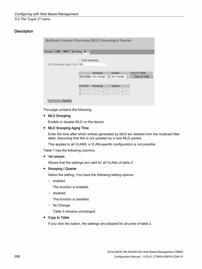
Configuring with Web Based Management 5.5 The "Layer 2" menu
SCALANCE XM-400/XR-500 Web Based Management (WBM) 286 Configuration Manual, 11/2015, C79000-G8976-C248-10
Description
The page contains the following:
● MLD Snooping
Enable or disable MLD on the device.
● MLD Snooping Aging Time
Enter the time after which entries generated by MLD are deleted from the multicast filter table. Assuming that this is not updated by a new MLD packet.
This applies to all VLANS; a VLAN-specific configuration is not possible
Table 1 has the following columns:
● 1st column
Shows that the settings are valid for all VLANs of table 2.
● Snooping / Querier
Select the setting. You have the following setting options:
– enabled
The function is enabled.
– disabled
The function is disabled.
– No Change
Table 2 remains unchanged.
● Copy to Table
If you click the button, the settings are adopted for all ports of table 2.

Configuring with Web Based Management 5.5 The "Layer 2" menu
SCALANCE XM-400/XR-500 Web Based Management (WBM) Configuration Manual, 11/2015, C79000-G8976-C248-10 287
Table 2 has the following columns:
● VLAN ID
Shows the VLAN to which the settings relate
● Snooping
Enable or disable MLD for the required VLAN. When enabled, the MLD entries are included the multicast filter table and MLD packets are forwarded.
● Querier
Enable or disable "Querier". The device sends MLD queries.
Steps in configuration Enabling the sending of MLD frames for a VLAN
1. Select the "MLD Snooping" check box.
2. Select the check box in the relevant row in table 2.
3. To apply the changes, click the "Set Values" button.
Enabling the sending of MLD frames for all VLANs
1. Select the "MLD Snooping" check box.
2. Select the entry "enabled" in the "Snooping" and"Querier" drop-down lists.
3. Click the "Copy to table" button. The check box is enabled for all VLANs in table 2.
4. To apply the changes, click the "Set Values" button.
5.5.16 Broadcast
Blocking the forwarding of broadcast frames On this page, you can block the forwarding of broadcast frames for individual ports.
Note
Some communication protocols work only with the support of broadcast. In these cases, blocking can lead to loss of data communication. Block broadcast only when you are sure that you do not need it.

Configuring with Web Based Management 5.5 The "Layer 2" menu
SCALANCE XM-400/XR-500 Web Based Management (WBM) 288 Configuration Manual, 11/2015, C79000-G8976-C248-10
Description of the displayed boxes Table 1 has the following columns:
● 1st column Shows that the settings are valid for all ports of table 2.
● Setting Select the setting from the drop-down list. You have the following setting options:
– enabled The blocking of broadcast frames is enabled.
– disabled The blocking of broadcast frames is disabled.
– No Change Table 2 remains unchanged.
● Copy to Table If you click the button, the setting is adopted for all ports of table 2.
Table 2 has the following columns:
● Port All available ports and the link aggregations are shown.
● Setting Enable or disable the blocking of broadcast frames.
Steps in configuration Enabling the blocking of broadcast frames for an individual port
1. Select the check box in the relevant row in table 2.
2. To apply the changes, click the "Set Values" button.

Configuring with Web Based Management 5.5 The "Layer 2" menu
SCALANCE XM-400/XR-500 Web Based Management (WBM) Configuration Manual, 11/2015, C79000-G8976-C248-10 289
Enabling the blocking of broadcast frames for all ports
1. In the "Setting" drop-down list, select the "Enabled" entry.
2. Click the "Copy to table" button. The check box is enabled for all ports in table 2.
3. To apply the changes, click the "Set Values" button.
5.5.17 PTP
5.5.17.1 General The following devices support time-of-day synchronization using PTP:
● SCALANCE XR528-6M
● SCALANCE XR552-12M
IEEE 1588 with SCALANCE devices The IEEE 1588v2 standard defines mechanisms with which highly precise time of day synchronization of devices in a network can be achieved. SCALANCE devices with suitable hardware support time synchronization according to IEEE 1588v2. The functionality is disabled on these devices when they are shipped and following a "Reset to factory defaults". To be able to use PTP, enable this function and configure every port that is on the synchronization path as well as ports that are blocked due to redundancy mechanisms. PTP can also be used with redundancy mechanisms in the ring such as HRP, standby linking of rings, MRP and RSTP. The following sections describe the configuration options of Web Based Management.
1588 Configuration On this page, you specify how the device will process PTP messages.
1588 Mode You can make the following settings:
● off The device does not process any PTP messages. PTP messages are, however, forwarded according to the rules of the switch.
● transparent The device adopts the function of a transparent clock and forwards PTP messages to other nodes while at the same time making entries in the correction field of the PTP message.

Configuring with Web Based Management 5.5 The "Layer 2" menu
SCALANCE XM-400/XR-500 Web Based Management (WBM) 290 Configuration Manual, 11/2015, C79000-G8976-C248-10
5.5.17.2 TC General
TC General
On this tab, you will find the general settings for PTP.
1588 Transparent Clock Configuration Delay Mechanism Specify the delay mechanism the device will work with:
● end to end
(Delay request response mechanism will be used)
Note
With end-to-end synchronization with more than 2 slaves, freak values > 100 ns can occur in the offset.
● peer to peer
(Peer delay mechanism will be used)
Domain Number Enter the domain number for the device here. The device ignores PTP messages with a different domain number. A SCALANCE device can only be assigned to one synchronization domain.
5.5.17.3 TC Port
TC port
This tab contains the port settings for PTP.

Configuring with Web Based Management 5.5 The "Layer 2" menu
SCALANCE XM-400/XR-500 Web Based Management (WBM) Configuration Manual, 11/2015, C79000-G8976-C248-10 291
1588 Transparent Clock Port Parameters Table 1 has the following columns:
● 1st column
Shows that the settings are valid for all ports.
● Setting
Select the required setting. If "No Change is selected, the entry in table 2 remains unchanged.
● Transport Mechanism The following settings are possible:
– Ethernet
– UDP IPv4
– No Change
If "No Change is selected, the entry in table 2 remains unchanged.
Table 2 shows detailed information about the individual ports:
● Port The port number. With modular devices, the slot number and port number are displayed separated by a dot.
● Setting
The port status. The following entries are possible:
– disabled The port is not involved in PTP.
– enabled The port processes PTP messages.

Configuring with Web Based Management 5.5 The "Layer 2" menu
SCALANCE XM-400/XR-500 Web Based Management (WBM) 292 Configuration Manual, 11/2015, C79000-G8976-C248-10
● Faulty Flag The error status relating to PTP.
– true
An error occurred.
– false No error has occurred on this port.
● Transport mechanism Choose how this port will handle PTP message data traffic. You can make different settings for the ports of a device, however, the relevant communications partner must support the selected transport mechanism. The following settings are possible:
– Ethernet
– UDP IPv4
5.5.18 RMON
5.5.18.1 Statistics
Statistics On this page you can specify the ports for which RMON statistics are displayed.
The RMON statistics are displayed on the "Information > Ethernet Statistics" page on the "Packet Size", "Packet Type" and "Packet Error" tabs.
Settings

Configuring with Web Based Management 5.5 The "Layer 2" menu
SCALANCE XM-400/XR-500 Web Based Management (WBM) Configuration Manual, 11/2015, C79000-G8976-C248-10 293
● RMON
If you select this check box, Remote Monitoring (RMON) allows diagnostics data to be collected on the device, prepared and read out using SNMP by a network management station that also supports RMON. This diagnostic data, for example port-related load trends, allow problems in the network to be detected early and eliminated.
Note
If you disable RMON, these statistics are not deleted but retain their last status.
● Port
Select the ports for which statistics will be displayed.
The table has the following columns:
● Select
Select the row you want to delete.
● Port
Shows the ports for which statistics will be displayed.
5.5.18.2 History
Samples of the statistics On this page, you can specify whether or not samples of the statistics are saved for a port. You can specify how many entries should be saved and at which intervals samples should be taken.
Settings

Configuring with Web Based Management 5.5 The "Layer 2" menu
SCALANCE XM-400/XR-500 Web Based Management (WBM) 294 Configuration Manual, 11/2015, C79000-G8976-C248-10
Table 1 has the following columns:
● 1st column
Shows that the settings are valid for all ports.
● Setting
Select the required setting. If "No Change" is selected, the entry in table 2 remains unchanged.
● Entries
Enter the maximum number of samples to be stored at the same time. If "No Change" is entered, the entry in table 2 remains unchanged.
● Interval [s]
Enter the interval after which the current status of the statistics will be saved as a sample. If "No Change" is entered, the entry in table 2 remains unchanged.
● Copy to Table
If you click the button, the settings are adopted for all ports of table 2.
Table 2 has the following columns:
● Port
Shows the port to which the settings relate.
● Setting
Enable or disable the recording of the history on the relevant port.
● Entries
Enter the maximum number of samples to be stored at the same time.
● Interval [s]
Enter the interval after which the current status of the statistics will be saved as a sample.

Configuring with Web Based Management 5.6 The "Layer 3 (IPv4)" menu
SCALANCE XM-400/XR-500 Web Based Management (WBM) Configuration Manual, 11/2015, C79000-G8976-C248-10 295
5.6 The "Layer 3 (IPv4)" menu
5.6.1 Configuration
Introduction The page contains the overview of the layer 3 functions for IPv4 of the device. On this page, you enable or disable the required layer 3 function.
The functions "Routing", "VRRP", "RIP" and "OSPF" are only available with layer 3.
Description of the displayed boxes The page contains the following boxes:
● Routing (only available with devices with a layer 3 license)
– Enabled
IPv4 routing is enabled. You can only enable the routing function if DHCP is disabled on all configured interfaces.
– Disabled
IPv4 routing is disabled. If IPv6 routing is enabled, this is also disabled.
● DHCP Relay Agent Enable or disable the DHCP relay agent. You can configure other settings in "Layer 3 (IPv4) > DHCP Relay Agent".
● VRRP (only available with devices with a layer 3 license) Enable or disable routing using VRRP. To use VRRP, first enable the routing function. You can configure other settings in "Layer 3 (IPv4) > VRRP".
● OSPF (only available with devices with a layer 3 license) Enable or disable routing using OSPF. To use OSPF, first enable the "Routing" function. You can configure other settings in "Layer 3 (IPv4) > OSPF".
● RIP (only available with devices with a layer 3 license) Enable or disable routing using RIP. To use RIP , first enable the routing function. You can configure other settings in "Layer 3 (IPv4) > RIP".

Configuring with Web Based Management 5.6 The "Layer 3 (IPv4)" menu
SCALANCE XM-400/XR-500 Web Based Management (WBM) 296 Configuration Manual, 11/2015, C79000-G8976-C248-10
Steps in configuration 1. To use the required function, select the corresponding check box.
2. Click the "Set Values" button.
5.6.2 Subnets
5.6.2.1 Overview
Creating subnets The page shows the subnets for the selected interface. If more than one subnet is available on an interface, in the first entry of this interface is of the address type "Primary".
All other subnets are created on this page. A subnet always relates to an interface. The interface is created on the "Configuration" tab.
Description of the displayed values The page contains the following boxes:
● Interface Select the interface on which you want to configure another subnet.
The table has the following columns:
● Select Select the row you want to delete.
● Interface Shows the interface.

Configuring with Web Based Management 5.6 The "Layer 3 (IPv4)" menu
SCALANCE XM-400/XR-500 Web Based Management (WBM) Configuration Manual, 11/2015, C79000-G8976-C248-10 297
● TIA Interface Shows the selected TIA interface.
● Interface Name Shows the name of the interface.
● MAC Address Shows the MAC address.
● IP Address Shows the IPv4 address of the subnet.
● Subnet Mask Shows the subnet mask.
● Address Type Displays the address type. The following values are possible:
– Primary The first IPv4 address that was configured on an IPv4 interface.
– Secondary All other IPv4 address that were configured on an IPv4 interface.

Configuring with Web Based Management 5.6 The "Layer 3 (IPv4)" menu
SCALANCE XM-400/XR-500 Web Based Management (WBM) 298 Configuration Manual, 11/2015, C79000-G8976-C248-10
● IP Assgn Method Shows how the IPv4 address is assigned. The following values are possible:
– Static The IPv4 address is static. You enter the settings in "IP Address" and "Subnet Mask".
– Dynamic (DHCP) The device obtains a dynamic IPv4 address from a DHCPv4 server.
● Address Collision Detection Status
If new IPv4 addresses become active in the network, the "Address Collision Detection" function checks whether this can result in address collisions. The allows IPv4 addresses that would be assigned twice to be detected.
Note
The function does not run a cyclic check.
This column shows the current status of the function. The following values are possible:
– Idle
The interface is not enabled and does not have an IPv4 address.
– Starting
This status indicates the start-up phase. In this phase, the device initially sends a query as to whether the planned IPv4 address already exists. If the address is not yet been assigned, the device sends the message that it is using this IP address as of now.
– Conflict
The interface is not enabled. The interface is attempting to use an IPv4 address address that has already been assigned.
– Defending
The interface uses a unique IPv4 address. Another interface is attempting to use the same IPv4 address.
– Active
The interface uses a unique IPv4 address. There are no collisions.
– Not supported
The function for detection of address collisions is not supported.
– Disabled
The function for detection of address collisions is disabled.
Steps in configuration 1. Select the interface from the "Interface" drop-down list.
2. Click the "Create" button. A new row is inserted in the table.
3. Click the "Set Values" button. Configure the subnet on the "Configuration" tab.

Configuring with Web Based Management 5.6 The "Layer 3 (IPv4)" menu
SCALANCE XM-400/XR-500 Web Based Management (WBM) Configuration Manual, 11/2015, C79000-G8976-C248-10 299
5.6.2.2 Configuration On this page, you configure the IPv4 interface.
Description of the displayed values The page contains the following boxes:
● Interface (name) Select the interface from the drop-down list.
● Interface Name Enter the name of the interface.
● MAC Address
Displays the MAC address of the selected interface.
● DHCP
Enable or disable the DHCP client for this IPv4 interface.
Note
If you want to operate the device as a router with several interfaces, disable DHCP on all interfaces.
● IP Address Enter the IPv4 address of the interface. The IPv4 addresses must not be used more than once.
● Subnet Mask Enter the subnet mask of the subnet you are creating. Subnets on different interfaces must not overlap.

Configuring with Web Based Management 5.6 The "Layer 3 (IPv4)" menu
SCALANCE XM-400/XR-500 Web Based Management (WBM) 300 Configuration Manual, 11/2015, C79000-G8976-C248-10
● Address Type Shows the address type. The following values are possible:
– Primary The first subnet of the interface.
– Secondary All further subnets of the interface.
● TIA Interface Select whether or not this interface should become the TIA Interface.
Steps in configuration 1. Select the interface from the "Interface (name)" drop-down list.
2. Enter a name for the Interface in "Interface Name".
3. Enter the IP address of the subnet in the "IP Address" column.
4. Enter the subnet mask belonging to the IPv4 address in the "Subnet Mask" column
5. Click the "Set Values" button.
5.6.3 Static Routes
Static route On this page, you create the static IPv4 routes.

Configuring with Web Based Management 5.6 The "Layer 3 (IPv4)" menu
SCALANCE XM-400/XR-500 Web Based Management (WBM) Configuration Manual, 11/2015, C79000-G8976-C248-10 301
Description of the displayed values The page contains the following boxes:
● Destination Network Enter the network address of the destination that can e reached via this route.
● Subnet Mask Enter the corresponding subnet mask.
● Gateway Enter the IPv4 address of the gateway via which this network address is reachable.
● Metric Enter the metric for the route. The metric corresponds to the quality of a connection, based for example on speed or costs. If there are several equal routes, the route with the lowest metric value is used. Range of values: 1 - 254
The table has the following columns:
● Select Select the row you want to delete.
● Destination Network Shows the network address of the destination.
● Subnet Mask Shows the corresponding subnet mask.
● Gateway Shows the IPv4 address of the next gateway.
● Interface Shows the interface of the route.
● Metric Enter the metric for the route. When creating the route, "not used" is entered automatically. The metric corresponds to the quality of a connection, based for example on speed or costs. If there are several equal routes, the route with the lowest metric value is used. Range of values: 1 - 254
● Status Shows whether or not the route is active.
Steps in configuration 1. Enter the network address of the destination in the "Destination Network" input box.
2. Enter the corresponding subnet mask in the "Subnet Mask" input box.
3. Enter the gateway in the "Gateway" input box.
4. Enter the weighting of the route in "Metric".
5. Click the "Create" button. A new entry is generated in the table.
6. Click the "Set Values" button.

Configuring with Web Based Management 5.6 The "Layer 3 (IPv4)" menu
SCALANCE XM-400/XR-500 Web Based Management (WBM) 302 Configuration Manual, 11/2015, C79000-G8976-C248-10
5.6.4 Route Maps
5.6.4.1 General
Route maps With route maps, you control how routing information is further processed. You can filter routing information and specify whether the information is further processed, modified or discarded.
Route maps operate according to the following principle:
● Routing information is compared with the filters of the route maps.
● The comparison is continued until the filters of a route map match the properties of an item of information.
● The information is then processed according to the route map settings:
– The routing information is discarded.
– The properties of the routing information are changed.
Settings
Figure 5-10 Route maps general
● Name
Enter the name for the route map.
● Sequence Number
Enter a number for the route map.
You can create several route maps with the same name but with different sequence numbers. The sequence numbers then specify the order in which the route maps are processed.

Configuring with Web Based Management 5.6 The "Layer 3 (IPv4)" menu
SCALANCE XM-400/XR-500 Web Based Management (WBM) Configuration Manual, 11/2015, C79000-G8976-C248-10 303
The table has the following columns:
● Select
Select the row you want to delete.
● Name
Shows the name of the route map.
● Sequence Number
Shows the sequence number of the route map.
● Action
Specify what happens to the routing information that matches the settings of the route map:
– permit
The routing information is further processed according to the settings you make in the "Set" tab.
– deny
The routing information is discarded.
5.6.4.2 Interface & Value Match On this page, you specify whether or not the routing information for a route map is filtered according to interfaces, metric or tags.
Settings
Figure 5-11 Filtering route maps and metric

Configuring with Web Based Management 5.6 The "Layer 3 (IPv4)" menu
SCALANCE XM-400/XR-500 Web Based Management (WBM) 304 Configuration Manual, 11/2015, C79000-G8976-C248-10
● Route Map (Name/Seq. No.)
Select a route map.
The created route maps are available to you.
● Type
Select the basis for the filtering:
– Interface
– Metric
– Tag
● Interface
Select an interface.
This box is active only if you have selected the "Interface" entry in the "Type" drop-down list.
● Metric
Enter a value for the metric.
This box is active only if you have selected the "Metric" entry in the "Type" drop-down list.
● Tag
Enter a value for the tag.
This box is active only if you have selected the entry "Tag in the "Type" drop-down list.
The table has the following columns:
● Select
Select the row you want to delete.
● Type
Shows the selected type:
– Interface
– Metric
– Tag
● Value
Shows the selected interface or the value of the metric or of the tag.

Configuring with Web Based Management 5.6 The "Layer 3 (IPv4)" menu
SCALANCE XM-400/XR-500 Web Based Management (WBM) Configuration Manual, 11/2015, C79000-G8976-C248-10 305
5.6.4.3 Destination Match On this page, you specify whether or not the routing information for a route map is filtered based on the destination IPv4 address.
Settings
Figure 5-12 Route Maps Destination Match
● Route Map (Name/Seq. No.)
Select a route map.
● IP Address
Enter the IPv4 address of the destination on which the filtering is based.
● Subnet Mask
Enter the subnet mask of the destination on which the filtering is based.
The table has the following columns:
● Select
Select the row you want to delete.
● IP Address
Shows the IPv4 address of the destination.
● Subnet Mask
Shows the subnet mask of the destination.
5.6.4.4 Next Hop Match On this page, you specify whether or not the filtering for a route map will be based on the router to which the routing information is sent next.

Configuring with Web Based Management 5.6 The "Layer 3 (IPv4)" menu
SCALANCE XM-400/XR-500 Web Based Management (WBM) 306 Configuration Manual, 11/2015, C79000-G8976-C248-10
Settings
Figure 5-13 Route Maps Next Hop Match
● Route Map (Name/Seq. No.)
Select a route map.
● IP Address
Enter the IP address of the router to which the routing information will be sent next.
The table has the following columns:
● Select
Select the row you want to delete.
● IP Address
Shows the IP address of the next router.
5.6.4.5 Create On this page, you specify whether or not the routing information will be changed by a route map.
You can only change the information of a "Permit" route map.
If, for example, you have filtered based on a certain metric, you can change the value of the metric here. The routing information is then forwarded with the new value.

Configuring with Web Based Management 5.6 The "Layer 3 (IPv4)" menu
SCALANCE XM-400/XR-500 Web Based Management (WBM) Configuration Manual, 11/2015, C79000-G8976-C248-10 307
Settings
Figure 5-14 Route maps set
● Route Map (Name/Seq. No.)
Select a route map.
The table has the following columns:
● Select
Select the row you want to delete.
● Name
Shows the name of the route map.
● Sequence Number
Shows the sequence number of the route map.
● Metric
Enter the new value for the metric with which the routing information will be forwarded.
● Tag
Enter the new value for the tag with which the routing information will be forwarded.
5.6.5 DHCP Relay Agent
5.6.5.1 General
DHCP Relay Agent If the DHCP server is in a different network, the device cannot reach the DHCP server. The DHCP relay agent intercedes between a DHCP server and the device. The DHCP relay agent forwards the port number of the device with the DHCP query to the DHCP server.
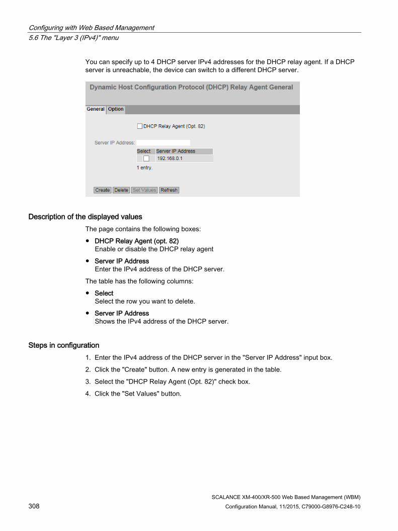
Configuring with Web Based Management 5.6 The "Layer 3 (IPv4)" menu
SCALANCE XM-400/XR-500 Web Based Management (WBM) 308 Configuration Manual, 11/2015, C79000-G8976-C248-10
You can specify up to 4 DHCP server IPv4 addresses for the DHCP relay agent. If a DHCP server is unreachable, the device can switch to a different DHCP server.
Description of the displayed values The page contains the following boxes:
● DHCP Relay Agent (opt. 82) Enable or disable the DHCP relay agent
● Server IP Address Enter the IPv4 address of the DHCP server.
The table has the following columns:
● Select Select the row you want to delete.
● Server IP Address Shows the IPv4 address of the DHCP server.
Steps in configuration 1. Enter the IPv4 address of the DHCP server in the "Server IP Address" input box.
2. Click the "Create" button. A new entry is generated in the table.
3. Select the "DHCP Relay Agent (Opt. 82)" check box.
4. Click the "Set Values" button.

Configuring with Web Based Management 5.6 The "Layer 3 (IPv4)" menu
SCALANCE XM-400/XR-500 Web Based Management (WBM) Configuration Manual, 11/2015, C79000-G8976-C248-10 309
5.6.5.2 Option
Parameters of the DHCP relay agent On this page, you can specify parameters for the DHCP server, for example the circuit ID. The circuit ID describes the origin of the DHCP query, for example which port received the DHCP query.
You specify the DHCP server on the "General" tab.
Description of the displayed values The page contains the following boxes:
Global configuration
● Circuit ID router index Enable or disable the check box. If you enable the check box, the generated circuit ID of the has the router index added to it.
● Circuit ID Receive VLAN ID Enable or disable the check box. If you enable the check box, the VLAN ID is added to the generated circuit ID

Configuring with Web Based Management 5.6 The "Layer 3 (IPv4)" menu
SCALANCE XM-400/XR-500 Web Based Management (WBM) 310 Configuration Manual, 11/2015, C79000-G8976-C248-10
● Circuit ID Receive Port Enable or disable the check box. If you enable the check box, the generated circuit ID has the receiving port added to it.
Note
You need to select a least one option.
● Remote ID Shows the device ID.
Interface-specific configuration
● Interface Select the interface from the drop-down list.
The table has the following columns:
● Select Select the row you want to delete.
● Interface Shows the interface.
Note
If you have not created an interface-specific configuration, the global configuration with the MAC address is used as the device ID.
● Remote ID Type Select the type of device ID from the drop-down list. You have the following options:
– IP Address The IPv4 address of the device is used as the device ID.
– MAC Address The MAC address of the device is used as the device ID.
– Free Text If you use "Free Text", you can enter the device name as the device ID in "Remote ID".
● Remote ID Enter the device name. The box can only be edited if you select the entry "Free Text" for "Remote ID Type".
● Circuit ID Type Select the type of circuit ID from the drop-down list. You have the following options:
– Predefined The circuit ID is created automatically based on the router index, VLAN ID or port.
– Free Number If you use "Free Number", you can enter the ID for "Circuit ID".
● Circuit ID Enter the circuit ID. The box can only be edited if you select the "Free number" entry for the "Circuit ID Type". Range of values: 1- 188

Configuring with Web Based Management 5.6 The "Layer 3 (IPv4)" menu
SCALANCE XM-400/XR-500 Web Based Management (WBM) Configuration Manual, 11/2015, C79000-G8976-C248-10 311
Steps in configuration Follow the steps below to specify automatic assignment of the parameters:
1. Select the "Circuit ID router index" check box.
2. Select the interface from the "Interface" drop-down list.
3. Click the "Create" button. A new row is inserted in the table
4. Select the "IP Address" entry in the "Remote ID Type" drop-down list. The IPv4 address is used as the device ID.
5. Select the "Predefined" entry in the "Circuit ID Type" drop-down list. The router index is added to the generated Circuit ID.
6. Click the "Set Values" button.
Follow the steps below to specify the parameters manually:
1. Select the "Circuit ID router index" check box.
2. Select the interface from the "Interface" drop-down list.
3. Click the "Create" button. A new row is inserted in the table
4. Select the "Free Text" entry in the "Remote ID Type" drop-down list. Enter the device ID in "Remote ID".
5. Select the "Free Number" entry in the "Circuit ID Type" drop-down list. Enter the ID in "Circuit ID".
6. Click the "Set Values" button.
5.6.6 VRRP
5.6.6.1 Router
Introduction Using the "Create" button, you can create new virtual routers. A maximum of 52 Virtual routers can be configured. You can configure other parameters on the "Configuration" tab.
Note • This function is available only with layer 3. • Select the "VRRP" check box to configure VRRP. • Simultaneous operation of VRRP and VRRPv3 is not possible. • You can only use VRRP in conjunction with VLAN interfaces. Router ports are not
supported.

Configuring with Web Based Management 5.6 The "Layer 3 (IPv4)" menu
SCALANCE XM-400/XR-500 Web Based Management (WBM) 312 Configuration Manual, 11/2015, C79000-G8976-C248-10
Description of the displayed values The page contains the following boxes:
● VRRP Enable or disable routing using VRRP.
● Reply to pings on virtual interfaces When enabled, the virtual IP addresses also reply to the ping.
● Interface Select the VLAN Interface that functions as the virtual router from the drop-down list.
● VRID Enter the ID of the virtual router in the input box. This ID defines the group of routers that form a virtual router (VR). In the group, this is the same. It can no longer be used for other groups. Valid values are 1.. 255.
The table has the following columns:
● Select Select the row you want to delete.
● Interface Shows the Interface that functions as the virtual router.
● VRID Shows the ID of the virtual router.
● Virtual MAC Address Shows the virtual MAC address of the virtual router.
● Primary IP Address Shows the numerically lowest IPv4 address in this VLAN. The entry 0.0.0.0 means that the "Primary" address on this VLAN is used. Otherwise all IPv4 addresses configured on this VLAN in the "Layer 3 (IPv4) > Subnets" menu are valid values.

Configuring with Web Based Management 5.6 The "Layer 3 (IPv4)" menu
SCALANCE XM-400/XR-500 Web Based Management (WBM) Configuration Manual, 11/2015, C79000-G8976-C248-10 313
● Router State Shows the current status of the virtual router. Possible values are:
– Master The router is the Master router and handles the routing functionality for all assigned IP addresses.
– Backup The router is the backup router. If the master router fails, the backup router takes over the tasks of the master router.
– Initialize The virtual router has just been turned on. It will soon change to the "Master" or "Backup" state.
● Master IP Address Shows the IPv4 address of the master router.
● Priority Shows the priority of the virtual router. Valid values are 1-255.
If an IPv4 address is assigned to the VRRP router that is also actually configured on the local IPv4 interface, the value 255 is entered automatically. All other priorities can be distributed freely among the VRRP routers. The higher the priority, the earlier the VRRP router becomes "Master".
● Advert. Interval Shows the interval at which the master router sends VRRP packets.
● Preempt Shows the precedence of a router when changing roles between backup and master.
– yes This router has precedence when changing roles.
– no This router does not have precedence when changing roles.
Steps in configuration 1. Select the "VRRP" check box.
2. Select the interface from the "Interface" drop-down list.
3. Enter the ID of the virtual router in the "VRID" input box.
4. Select the "Reply to pings on virtual interfaces" check box so that virtual IP addresses reply to pings as well.
5. Click the "Create" button. A new row is inserted in the table.
6. Click the "Set Values" button. To configure the virtual router, click on the "Configuration" tab.

Configuring with Web Based Management 5.6 The "Layer 3 (IPv4)" menu
SCALANCE XM-400/XR-500 Web Based Management (WBM) 314 Configuration Manual, 11/2015, C79000-G8976-C248-10
5.6.6.2 Configuration
Introduction On this page, you configure the virtual router.
Note
This function is available only with layer 3.
Description of the displayed values The page contains the following boxes:
● Interface / VRID Select the ID of the virtual router you are configuring from the drop-down list.
● Primary IP Address Select the numerically lowest IPv4 address from the drop-down list: If the router becomes master router, the router uses this IPv4 address.
Note
If you only configure one subnet on this VLAN, no entry is necessary. The entry is then 0.0.0.0. If you configure more than one subnet on the VLAN and you want a specific IPv4 address to be used as the source address for VRRP packets, select the IPv4 address from the drop-down list. Otherwise, the numerically lowest IPv4 address will be used.
● Master If this option is enabled, the numerically lowest IPv4 address is entered for "Associated IP Address". This means that the highest priority IPv4 address of the VRRP router is used as the virtual IPv4 address of the virtual master router. The option must be disabled for the backup routers in this group and the IP address of the router in "Associated IP address" must be used.

Configuring with Web Based Management 5.6 The "Layer 3 (IPv4)" menu
SCALANCE XM-400/XR-500 Web Based Management (WBM) Configuration Manual, 11/2015, C79000-G8976-C248-10 315
● Priority Enter the priority of this virtual router. Valid values are 1-255.
If an IPv4 address is assigned to the VRRP router that is also actually configured on the local IPv4 interface, the value 255 is entered automatically. All other priorities can be distributed freely among the VRRP routers. The higher the priority, the earlier the VRRP router becomes "Master".
● Advertisement Interval Enter the interval in seconds after which a master router sends a VRRP packet again.
● Preempt lower priority Master Allow the precedence when changing roles between backup and master based on the selection process.
Steps in configuration To configure a virtual router as the master router, follow the steps below:
1. Select the ID of the virtual router you want to configure from the "Interface / VRID" drop-down list.
2. Select the "Status" check box.
3. Select the source address from the "Primary IP Address" drop-down list.
4. From the "Priority" drop-down list, enter the priority of this virtual router.
5. Select the "Master" check box.
6. Enter the interval in "Advertisement Interval".
7. Select the "Preempt lower priority Master" check box.
8. Click the "Set Values" button.
5.6.6.3 Address overview
Overview This page shows which IPv4 addresses the virtual router monitors. Each virtual router can monitor a maximum of 10 IPv4 addresses.
Note
This function is available only with layer 3.

Configuring with Web Based Management 5.6 The "Layer 3 (IPv4)" menu
SCALANCE XM-400/XR-500 Web Based Management (WBM) 316 Configuration Manual, 11/2015, C79000-G8976-C248-10
Description of the displayed boxes: The table has the following columns:
● Interface Shows the Interface that functions as the virtual router.
● VRID Shows the ID of this virtual router.
● Number of addresses Shows the number of IPv4 addresses.
● Assigned IP address (1) ... Assigned IP address (10) Shows the router IPv4 addresses monitored by this virtual router. If a router takes over the role of master, the routing function is taken over by this router for all these IPv4 addresses.
5.6.6.4 Address Configuration
Creating or changing the monitored IPv4 addresses On this page, you can create, modify or delete the IPv4 addresses to be monitored. A maximum of 10 IPv4 addresses can be monitored by a virtual router.
Note
This function is available only with layer 3.

Configuring with Web Based Management 5.6 The "Layer 3 (IPv4)" menu
SCALANCE XM-400/XR-500 Web Based Management (WBM) Configuration Manual, 11/2015, C79000-G8976-C248-10 317
Description of the displayed values The page contains the following boxes:
● Interface / VRID Select the virtual router from the drop-down list.
● Associated IP address Enter the IPv4 address that the virtual router will monitor. A maximum of 10 IPv4 addresses are possible.
The table has the following columns:
● Select Select the row you want to delete.
● Associated IP Address Shows the IPv4 addresses that the virtual router monitors.
Steps in configuration 1. Select the ID of the virtual router from the "Interface / VRID" drop-down list.
2. Enter the IPv4 address that the virtual router will monitor.
3. Click the "Create" button. A new entry is generated in the table.
5.6.7 VRRPv3
5.6.7.1 Router
Introduction Using the "Create" button, you can create new virtual routers. A maximum of 52 Virtual routers can be configured. You can configure other parameters on the "Configuration" tab.
Note • This function is available only with layer 3. • Simultaneous operation of VRRP and VRRPv3 is not possible. • Select the "VRRPv3" check box to configure VRRPv3. • You can use VRRPv3 on VLAN interfaces. Router ports are not supported.

Configuring with Web Based Management 5.6 The "Layer 3 (IPv4)" menu
SCALANCE XM-400/XR-500 Web Based Management (WBM) 318 Configuration Manual, 11/2015, C79000-G8976-C248-10
Description The page contains the following:
● VRRPv3
Enable or disable routing using VRRPv3. Can only be enabled when "Layer 3 > Configuration" "IPv6 Routing" is enabled.
● Reply to pings on virtual interfaces
When enabled, the virtual IPv4 addresses also reply to the ping.
● Interface
Select the required VLAN interface operating as virtual router.
● VRID
Enter the ID of the virtual router. This ID defines the group of routers that form a virtual router (VR). In the group, this is the same. It can no longer be used for other groups. Valid values are 1.. 255.
The table has the following columns:
● Select
Select the check box in the row to be deleted.
● Interface
Shows the Interface that functions as the virtual router.
● VRID
Shows the ID of the virtual router.
● Virtual MAC Address
Shows the virtual MAC address of the virtual router.

Configuring with Web Based Management 5.6 The "Layer 3 (IPv4)" menu
SCALANCE XM-400/XR-500 Web Based Management (WBM) Configuration Manual, 11/2015, C79000-G8976-C248-10 319
● Primary IP Address
Shows the numerically lowest IPv4 address in this VLAN. The entry 0.0.0.0 means that the "Primary" address on this VLAN is used. Otherwise all IPv4 addresses configured on this VLAN in the "Layer 3 (IPv4) > Subnets" menu are valid values.
● Router State
Shows the current status of the virtual router. Possible values are:
– Master
The router is the master router and handles the routing functionality for all assigned IPv4 addresses.
– Backup
The router is the backup router. If the master router fails, the backup router takes over the tasks of the master router.
– Initialize
The virtual router has just been turned on. It will soon change to the "Master" or "Backup" state.
● Master IP Address
Shows the IPv4 address of the master router.
● Priority
Shows the priority of the virtual router. Valid values are 1-254. If an IPv4 address is assigned to the VRRP router that is also actually configured on the local IPv4 interface, the value 255 is entered automatically. All other priorities can be distributed freely among the VRRP routers. The higher the priority, the earlier the VRRP router becomes "Master".
● Advert. Internal
Shows the interval at which the master router sends VRRPv3 packets.
● Preempt
Shows the precedence of a router when changing roles between backup and master.
– yes
This router has precedence when changing roles.
– no
This router does not have precedence when changing roles.
Steps in configuration 1. Enable "VRRPv3".
2. Select the required interface.
3. Enter the ID of the virtual router in "VRID".
4. Select the "Reply to pings on virtual interfaces" option so that virtual IPv4 addresses reply to pings as well.

Configuring with Web Based Management 5.6 The "Layer 3 (IPv4)" menu
SCALANCE XM-400/XR-500 Web Based Management (WBM) 320 Configuration Manual, 11/2015, C79000-G8976-C248-10
5. Click the "Create" button. A new row is inserted in the table.
6. Click the "Set Values" button. To configure the virtual router, click on the "Configuration" tab.
5.6.7.2 Configuration
Introduction On this page, you configure the virtual router.
Note
This function is available only with layer 3.
Description The page contains the following:
● Interface / VRID
Select the ID of the virtual router to be configured.
● Primary Address
Select the primary IPv4 address. If the router becomes master router, the router uses this IPv4 address.
Note
If you only configure one subnet on this VLAN, no entry is necessary. The entry is then 0.0.0.0. If you configure more than one subnet on the VLAN and you want a specific IPv4 address to be used as the source address for VRRP packets, select the IPv4 address. Otherwise, the numerically lowest IPv4 address will be used.

Configuring with Web Based Management 5.6 The "Layer 3 (IPv4)" menu
SCALANCE XM-400/XR-500 Web Based Management (WBM) Configuration Manual, 11/2015, C79000-G8976-C248-10 321
● Master
If enabled, the numerically lowest IPv4 address is entered for "Associated IP Address". This means that the numerically lowest IPv4 address of the VRRP router is used as the virtual IP address of the virtual master router. The backup routers in this group must disable the option and use the IPv4 address of the router in "Associated IP address".
● Priority
Enter the priority of this virtual router. Valid values are 1-254. If an IPv4 address is assigned to the VRRPv3 router that is also actually configured on the local IPv4 interface, the value 255 is entered automatically. All other priorities can be distributed freely among the VRRPv3 routers. The higher the priority, the earlier the VRRPv3 router becomes "Master".
● Advertisement interval
Enter the interval in seconds after which a master router sends a VRRPv3 packet again.
● Preempt lower priority Master.
Allow precedence when changing roles between backup and master based on the selection process.
● VRRP Compatible Mode
When enabled, the VRRPv3 router also sends and receives VRRPv2 frames in addition to VRRPv3 frames for configured IPv4 addresses. Only necessary when some VRRP routers do not support VRRPv3
Steps in configuration To configure a virtual router as the master router, follow the steps below:
1. Select the ID of the virtual router you want to configure from the "Interface / VRID" drop-down list.
2. Select the "Status" check box.
3. Select the source address from the "Primary Address" drop-down list.
4. From the "Priority" drop-down list, enter the priority of this virtual router.
5. Select the "Master" check box.
6. Enter the interval in "Advertisement Interval".
7. Select the "Preempt lower priority Master" check box.
8. Click the "Set Values" button.

Configuring with Web Based Management 5.6 The "Layer 3 (IPv4)" menu
SCALANCE XM-400/XR-500 Web Based Management (WBM) 322 Configuration Manual, 11/2015, C79000-G8976-C248-10
5.6.7.3 Addresses Overview
Overview This page shows which IPv4 addresses the virtual router monitors. Each virtual router can monitor a maximum of 10 IPv4 addresses.
Note
This function is available only with layer 3.
Description of the displayed values The table has the following columns:
● Interface
Shows the Interface that functions as the virtual router.
● VRID
Shows the ID of this virtual router.
● Number of Addresses
Shows the number of IPv4 addresses.
● Associated IP Address (1) ...Associated IP Address (10)
Shows the router IPv4 addresses monitored by this virtual router. If a router takes over the role of master, the routing function is taken over by this router for all these IPv4 addresses.

Configuring with Web Based Management 5.6 The "Layer 3 (IPv4)" menu
SCALANCE XM-400/XR-500 Web Based Management (WBM) Configuration Manual, 11/2015, C79000-G8976-C248-10 323
5.6.7.4 Addresses Configuration
Creating or changing the monitored IP addresses On this page, you can create, modify or delete the IPv4 addresses to be monitored. A maximum of 10 IPv4 addresses can be monitored by a virtual router.
Note
This function is available only with layer 3.
Description The page contains the following:
● Interface / VRID
Select the ID of the virtual router.
● Associated IP Address
Enter the IPv4 address that the virtual router will monitor. A maximum of 10 IPv4 addresses are possible.
The table has the following columns:
● Select
Select the check box in the row to be deleted
● Associated IP Address
Shows the IPv4 addresses that the virtual router monitors.
Steps in configuration 1. Select the ID of the virtual router.
2. Enter the IPv4 address that the virtual router will monitor.
3. Click the "Create" button. A new entry is generated in the table.

Configuring with Web Based Management 5.6 The "Layer 3 (IPv4)" menu
SCALANCE XM-400/XR-500 Web Based Management (WBM) 324 Configuration Manual, 11/2015, C79000-G8976-C248-10
5.6.8 OSPFv2
5.6.8.1 Configuration
Introduction On this page, you configure the routing using OSPFv2..
Note
This function is available only with layer 3.
Description of the displayed values The page contains the following boxes
● OSPFv2 Enable or disable routing using OSPFv2.
● Router ID Enter the name of one of the OSPFv2 interfaces. The name is entered in the IP address format and does not need to match the local IP address. The router ID must be unique in the network.
● OSPFv2-RFC1583 Compatibility Enable the option if you still have old OSPFv2 routers in operation that are not compatible with RFC 2328.

Configuring with Web Based Management 5.6 The "Layer 3 (IPv4)" menu
SCALANCE XM-400/XR-500 Web Based Management (WBM) Configuration Manual, 11/2015, C79000-G8976-C248-10 325
● Border Router Shows the status of the OSPFv2 router. If the local system is an active member in at least 2 areas, this is an area border router.
● AS Border Router Specify whether the router is an AS border router. An AS border router intercedes between multiple autonomous systems, for example if you have an additional RIP network. An AS border router is also necessary to add and to distribute static routes.
● New LSA Received Shows the number of received LSAs. Updates and local LSAs are not counted.
● New LSA Configured Shows the number of different LSAs sent by this local system.
● External LSA Maximum To limit the number of entries of external LSAs in the database, enter the maximum number of external LSAs.
● Exit Interval [s] Enter the interval after which the OSPFv2 router once again attempts to come out of the overflow status. A 0 means that the OSPF router attempts to exit the overflow status only following a restart.
● Inbound Filter
Select a route map that filters inbound routes.
● Redistribute Routes (Default/Connected/Static) Specify which known routes are distributed using OSPFv2. You can make different decisions for the route types Default, Connected and Static.
Note
The options can only be enabled on an AS border router. Enabling the Default and Static options, in particular, can cause problems if they are enabled at too many points in the network, for example, forwarding loops.
● Route Map
Select a route map that filters which routes are forwarded using RIPv2.
Steps in configuration 1. Select the "OSPFv2" check box.
2. Enter the ID of the router in the "Router ID" input box.
3. Select the "AS Border Router" check box.
4. Click the "Set Values" button.

Configuring with Web Based Management 5.6 The "Layer 3 (IPv4)" menu
SCALANCE XM-400/XR-500 Web Based Management (WBM) 326 Configuration Manual, 11/2015, C79000-G8976-C248-10
5.6.8.2 Areas
Overview An autonomous system can be divided into smaller areas.
On this page, you can view, create, modify or delete the areas of the router.
Note
This function is available only with layer 3.
Description of the displayed values The page contains the following boxes:
● Area ID Enter the identifier of the area. The database is synchronized for all routers of an area. The area identifier must be unique in the network. The area identifier is a 32-bit number with the following format: x.x.x.x where x = 0 ... 255 The area identifier 0.0.0.0 is reserved for the backbone area and cannot be deleted.
This table contains the following columns:
● Select
Select the row you want to delete.
● Area ID Shows the identifier of the area.

Configuring with Web Based Management 5.6 The "Layer 3 (IPv4)" menu
SCALANCE XM-400/XR-500 Web Based Management (WBM) Configuration Manual, 11/2015, C79000-G8976-C248-10 327
● Area Type Select the area type in the drop-down list.
– Standard
– Stub
– NSSA
– Backbone
● Summary Specify whether summary LSAs are generated for this area.
– Summary: Summary LSAs are generated and sent to the area.
– No Summary: Summary LSAs are not generated and sent to the area.
● Metric
Displays the costs for the OSPFv2 interface.
● Updates Shows the number of recalculations of the routing tables.
● LSA Count Shows the number of LSAs in the database.
● Area BR Shows the number of reachable area border routers (ABR) within this area.
● AS BR Shows the number of reachable autonomous system border routers (ASBR) in this area.
Steps in configuration 1. Enter the ID for the area in the "Area ID" input box.
2. Click the "Create" button. A new entry is generated in the table.
3. Select the type of area, for example Stub in the "Area Type" drop-down list.
4. Select the "Summary LSA" entry in the "Summary" drop-down list.
5. Click the "Set Values" button.
5.6.8.3 Area Range
Creating a new OSPFv2 area range Using the "New Entry" button in the "OSPFv2 Area Ranges" menu, up to four networks can be grouped together under one area ID. The method is used only with area border routers. This means that an area border router only advertises one route for grouped areas to the outside.
Note
This function is available only with layer 3.

Configuring with Web Based Management 5.6 The "Layer 3 (IPv4)" menu
SCALANCE XM-400/XR-500 Web Based Management (WBM) 328 Configuration Manual, 11/2015, C79000-G8976-C248-10
Description of the displayed boxes The page contains the following boxes:
● Area ID Select the ID of the area from the drop-down list. You specify the ID on the "Areas" tab.
● Subnet Address Enter the IPv4 address of the network that will be grouped.
● Subnet mask Enter the subnet mask of the network that will be grouped.
This table contains the following columns:
● Select
Select the row you want to delete.
● Area ID Shows the ID of the area.
● Subnet Address Shows the IP address of the network that will be grouped.
● Subnet Mask Shows the subnet mask of the network that will be grouped.
● Advertise Enable this option to advertise the grouped network.
Steps in configuration 1. Select the ID of the area from the drop-down list.
2. Enter the IP address of the network that will be grouped.
3. Enter the subnet mask of the network that will be grouped.
4. Click the "Create" button. A new entry is generated in the table.
5. Enable the "Advertise" option to advertise the grouped network.
6. Click the "Set Values" button.

Configuring with Web Based Management 5.6 The "Layer 3 (IPv4)" menu
SCALANCE XM-400/XR-500 Web Based Management (WBM) Configuration Manual, 11/2015, C79000-G8976-C248-10 329
5.6.8.4 Interfaces
Overview On this page, you can configure OSPFv2 interfaces.
Note
This function is available only with layer 3.
Description of the displayed boxes The page contains the following boxes:
● IP Address Select the IP address of the OSPF interface from the drop-down list.
● Area ID Select the ID of the area that is connected to the OSPFv2 interface from the drop-down list.
Note
For the secondary interface select the same Area ID as for the corresponding primary interface. The information whether an address type is primary or secondary can be found in the "Address Type" column on the "Layer 3 (IPv4) > Subnets > Overview" page.
Select the ID of the area that is connected to the OSPFv2 interface from the drop-down list. The table has the following columns:
● Select
Select the row you want to delete.
● IP address Shows the IPv4 address of the OSPFv2 interface
Configuring with Web Based Management 5.6 The "Layer 3 (IPv4)" menu
SCALANCE XM-400/XR-500 Web Based Management (WBM) 330 Configuration Manual, 11/2015, C79000-G8976-C248-10
● Area ID Select the ID of the area that is connected to the OSPFv2 interface from the drop-down list.
● OSPF Status Specify whether OSPFv2 is active on the Interface.
– Enabled: OSPFv2 is enabled on the interface.
– Disabled: OSPFv2 is disabled on the interface.
● Metric Enter the costs for the OSPFv2 interface.
● Priority Enter the router priority. The priority is only relevant for selecting the designated router or designated border router. This parameter can be selected differently on routers within the same subnet. Range of values: 0 to 255 Default setting: 1
● Trans. Delay Enter the expected delay when sending a connection update. Range of values: 1 s to 3600 s Default: 1 s
● Retrans. Delay Enter the time after which an OSPFv2 packet is transferred again if no confirmation was received. Range of values: 1 s to 3600 s Default: 5 s
● Hello Interval Enter the interval between two Hello packets. Range of values: 1 s to 65,535 s Default: 10 s
● Dead Interval Enter the interval after which the neighbor router is marked as "failed" if no more Hello packets are received from it during this time. Default: 40 s
Steps in configuration 1. Select the IPv4 address of the OSPFv2 interface from the "IP Address" drop-down list.
2. Select the ID of the area with which the OSPFv2 interface is connected from the "Area ID" drop-down list.
3. Click the "Create" button. A new entry is generated in the table.
4. Select the check box beside "OSPF Status".
5. In "Transit Delay", "Retrans. Delay" and "Dead Interval"enter suitable values or use the default settings .
6. Click the "Set Values" button.

Configuring with Web Based Management 5.6 The "Layer 3 (IPv4)" menu
SCALANCE XM-400/XR-500 Web Based Management (WBM) Configuration Manual, 11/2015, C79000-G8976-C248-10 331
5.6.8.5 Interface Authentication
Configuring the interface authentication On this page, you define the authentication of the interface.
Description of the displayed boxes The page contains the following boxes:
● OSPF interface Select the OSPFv2 interface for which you want to configure authentication.
● Authentication Type
Select the authentication method. You have the following options:
– None
No authentication
– Simple
Authentication using an unencrypted password
– MD5
Authentication using MD5

Configuring with Web Based Management 5.6 The "Layer 3 (IPv4)" menu
SCALANCE XM-400/XR-500 Web Based Management (WBM) 332 Configuration Manual, 11/2015, C79000-G8976-C248-10
Section "Simple Authentication"
● Password
Enter a password.
● Confirmation
Confirm the entered password.
Section "MD5 Authentication"
● Authentication Key ID
Enter the identifier of the MD5 authentication key.
Enter the ID for MD5 authentication with which the password will be used as a key.
Since the key ID is transferred with the protocol, the same key must be stored under the same key ID on all neighboring routers.
The table has the following columns:
● Select
Select the row you want to delete.
● Authentication Key ID
Can only be edited if you set the MD5 authentication method. It is only possible to use several keys there.
● MD5 Key
Enter the MD5 key.
● MD5 Key Confirmation
Confirm the entered key.
● Youngest Key ID
Shows whether or not the MD5 key is the latest key ID.
Steps in configuration 1. Select the OSPFv4 interface and the authentication method from the drop-down lists.
2. Enter the following data in the relevant input box:
– Password
– Confirmation of the password
– Identifier of the MD5 authentication key
3. Click the "Create" button.
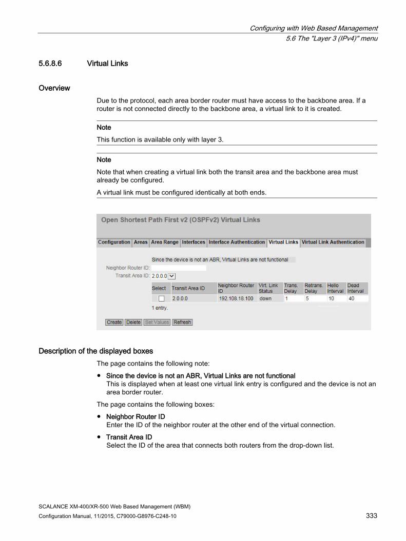
Configuring with Web Based Management 5.6 The "Layer 3 (IPv4)" menu
SCALANCE XM-400/XR-500 Web Based Management (WBM) Configuration Manual, 11/2015, C79000-G8976-C248-10 333
5.6.8.6 Virtual Links
Overview Due to the protocol, each area border router must have access to the backbone area. If a router is not connected directly to the backbone area, a virtual link to it is created.
Note
This function is available only with layer 3.
Note
Note that when creating a virtual link both the transit area and the backbone area must already be configured.
A virtual link must be configured identically at both ends.
Description of the displayed boxes The page contains the following note:
● Since the device is not an ABR, Virtual Links are not functional This is displayed when at least one virtual link entry is configured and the device is not an area border router.
The page contains the following boxes:
● Neighbor Router ID Enter the ID of the neighbor router at the other end of the virtual connection.
● Transit Area ID Select the ID of the area that connects both routers from the drop-down list.

Configuring with Web Based Management 5.6 The "Layer 3 (IPv4)" menu
SCALANCE XM-400/XR-500 Web Based Management (WBM) 334 Configuration Manual, 11/2015, C79000-G8976-C248-10
This table contains the following columns:
● Selektieren
Select the row you want to delete.
● Transit Area ID Shows the ID via which the two routers are connected.
● Neighbor Router ID Shows the ID of the neighbor router at the other end of the virtual connection.
● Virt. Link Status Specify the status of the virtual link. The following states are possible:
– down: The virtual link is inactive.
– point-to-point: The virtual link is active.
● Trans. Delay Enter the expected delay when sending a link update packet. Range of values: 1 s to 3600 s Default: 1 s
● Retrans. Delay Enter the time after which a packet is transferred again if no confirmation was received. Range of values: 1 s to 3600 s Default: 5 s
● Hello Interval Enter the interval between two Hello packets. Range of values: 1 s to 65,535 s Default: 10 s
● Dead Interval Enter the interval after which the neighbor router counts as "failed" if no more Hello packets are received from it during this time. Default setting: 40 s
Steps in configuration 1. Enter the ID of the neighbor router at the other end of the virtual link in "Neighbor Router
ID".
2. Select the area ID that connects the two routers from the "Transit Area ID" drop-down list.
3. Click the "Create" button. A new entry is generated in the table.
4. Enter suitable values for "Transit Delay", "Retrans. Delay" and "Dead Interval".
5. Click the "Set Values" button.

Configuring with Web Based Management 5.6 The "Layer 3 (IPv4)" menu
SCALANCE XM-400/XR-500 Web Based Management (WBM) Configuration Manual, 11/2015, C79000-G8976-C248-10 335
5.6.8.7 Virtual Link Authentication
Configuring the interface login On this page, you define the authentication of the interface.
Description of the displayed boxes The page contains the following boxes:
● Virtual Link (Area/Neighbor)
Select the virtual link for which you want to configure authentication.
● Authentication Type
Select the authentication method. You have the following options:
– None
No authentication
– Simple
Authentication using an unencrypted password
– MD5
Authentication using MD5
Section "Simple Authentication"
● Password
Enter a password.
● Confirmation
Confirm the entered password.
Configuring with Web Based Management 5.6 The "Layer 3 (IPv4)" menu
SCALANCE XM-400/XR-500 Web Based Management (WBM) 336 Configuration Manual, 11/2015, C79000-G8976-C248-10
Section "MD5 Authentication"
● Authentication Key ID
Enter the identifier of the MD5 authentication key.
Enter the ID for MD5 authentication with which the password will be used as a key.
Since the key ID is transferred with the protocol, the same key must be stored under the same key ID on all neighboring routers.
The table has the following columns:
● Select
Select the row you want to delete.
● Authentication Key ID
Can only be edited if you set the MD5 authentication method. It is only possible to use several keys there.
● MD5 Key
Enter the MD5 key.
● MD5 Key Confirmation
Confirm the entered key.
● Youngest Key ID
Shows whether or not the MD5 key is the latest key ID.
Steps in configuration Follow these steps:
1. Select the virtual connection and the authentication method from the drop-down lists.
2. Enter the following data in the relevant input box:
– Password
– Confirmation of the password
– Identifier of the MD5 authentication key
3. Click the "Set Values" button.

Configuring with Web Based Management 5.6 The "Layer 3 (IPv4)" menu
SCALANCE XM-400/XR-500 Web Based Management (WBM) Configuration Manual, 11/2015, C79000-G8976-C248-10 337
5.6.9 RIPv2
5.6.9.1 Configuration On this page, you configure the routing using RIPv2.
Note
RIPv2 is available only on layer 3.
Settings
Figure 5-15 RIPv2 Configuration
● RIPv2
Enable or disable routing using RIPv2.
● Inbound Filter
Select a route map that filters inbound routes.
● Redistribute Routes
Specify which known routes are distributed using RIPv2.
The following types of route exist:
– Static Default
– Connected
– Static
– OSPF
● Route Map
Select a route map that filters which routes are forwarded using RIPv2.

Configuring with Web Based Management 5.6 The "Layer 3 (IPv4)" menu
SCALANCE XM-400/XR-500 Web Based Management (WBM) 338 Configuration Manual, 11/2015, C79000-G8976-C248-10
5.6.9.2 Interfaces
Overview On this page, you can configure RIPv2 interfaces.
Note
RIPv2 is available only on layer 3.
Settings
Figure 5-16 RIPv2 interfaces
● IP Address
Select the IPv4 address of the RIPv2 interface.
This table contains the following columns:
● Select
Select the row you want to delete.
● IP Address
Shows the IPv4 address of the RIPv2 interface
Configuring with Web Based Management 5.6 The "Layer 3 (IPv4)" menu
SCALANCE XM-400/XR-500 Web Based Management (WBM) Configuration Manual, 11/2015, C79000-G8976-C248-10 339
● Send Updates
Select the way in which updates are sent:
– no send
No updates are sent.
– RIPv1
Updates for RIPv1 are sent.
– RIPv1-compat.
RIPv2 updates are sent as broadcasts according to the rules of RIPv1.
– RIPv2
Updates for RIPv2 are sent as multicasts.
– RIPv1 demand/RIPv2 demand
RIP packets are sent only as a response to an explicit query.
● Receive Updates
Select the form in which received updates are accepted:
– no receive
No updates are received.
– RIPv1
Only updates of RIPv1 are received.
– RIPv2
Only updates of RIPv2 are received.
– RIPv1/v2
Updates of RIPv1 and RIPv2 are received.
● Default Metric
Enter the costs for the RIPv2 interface.

Configuring with Web Based Management 5.7 The "Layer 3 (IPv6)" menu
SCALANCE XM-400/XR-500 Web Based Management (WBM) 340 Configuration Manual, 11/2015, C79000-G8976-C248-10
5.7 The "Layer 3 (IPv6)" menu
5.7.1 Configuration
Introduction The page contains the overview of the layer 3 functions for IPv6. On this page, you enable or disable the required layer 3 function.
The functions "IPv6 Routing", "VRRPv3" and "OSPFv3" are only available with Layer 3 (IPv6).
Description The page contains the following:
● IPv6 Routing (only available with devices with a layer 3 license)
– Enabled
IPv6 routing is enabled. If IPv4 routing is not enabled on the device this is also enabled with this function.
– Disabled
IPv6 routing is disabled.
● VRRPv3 (only available with devices with a layer 3 license)
Enable or disable routing using VRRPv3. To use VRRPv3 , first enable the IPv6 routing function. You can configure other settings in "Layer 3 (IPv6)> VRRPv3".
● OSPFv3 (only available with devices with a layer 3 license)
Enable or disable routing using OSPFv3. To use OSPFv3 , first enable the IPv6 routing function. You can configure other settings in "Layer 3 (IPv6) > OSPFv3".

Configuring with Web Based Management 5.7 The "Layer 3 (IPv6)" menu
SCALANCE XM-400/XR-500 Web Based Management (WBM) Configuration Manual, 11/2015, C79000-G8976-C248-10 341
Steps in configuration 1. To use the required function, select the corresponding check box.
2. Click the "Set Values" button.
5.7.2 Subnets
Connected Subnets On this page, you can enable IPv6 on the interface. The interface is also called an IPv6 interface. An IPv6 interface can have several IPv6 addresses.
Description The page contains the following:
● Interface
Select the IP interface on which IPv6 will be enabled.
● IPv6 Enable
Enable or disable IPv6 on the interface.
Note Disabling IPv6
As soon as IPv6 is enabled on the IP interface, IPv6 can only be disabled by removing the interface.
Configuring with Web Based Management 5.7 The "Layer 3 (IPv6)" menu
SCALANCE XM-400/XR-500 Web Based Management (WBM) 342 Configuration Manual, 11/2015, C79000-G8976-C248-10
● IPv6 Address
Enter the IPv6 address. The entry depends on the selected address type.
● Prefix Length
Enter the number of left-hand bits belonging to the prefix
● IPv6 Address Type
Select the address type.
– Unicast
– Anycast
– Link Local IPv6 address is only valid on the link
The table has the following columns:
● Select
Select the check box in the row to be deleted.
● Interface Name
Shows the name of the interface.
● IPv6 Address
Shows the IP address of the subnet.
● Prefix Length
Shows the prefix length.
● IPv6 Address Type
Displays the address type. The following values are possible:
– Unicast
– Anycast
– Link Local
Steps in configuration Forming a link local address automatically
1. Select the required interface.
2. Enable IPv6.
3. Click the "Create" button. In the table an entry with the interface is created and the automatically formed IPv6 address is displayed.
Assigning link local address
1. Select the required interface.
2. Enable IPv6.
3. In "IPv6 Address" enter the link local address, e.g. FE80::21B:1BFF:FE40:9155
4. Enter "128" in "Prefix Length".

Configuring with Web Based Management 5.7 The "Layer 3 (IPv6)" menu
SCALANCE XM-400/XR-500 Web Based Management (WBM) Configuration Manual, 11/2015, C79000-G8976-C248-10 343
5. For "IPv6 Address Type" select the entry "Link Local".
6. Click the "Create" button. In the table an entry with the interface is created and the IPv6 address is displayed.
5.7.3 DHCPv6 client
5.7.3.1 DHCPv6 client On this page, you specify whether the DHCPv6 client receives not only the configuration settings but also the IPv6 address or supports the "prefix delegation" function.
Prefix delegation
The DHCPv6 server delegates the distribution of the IPv6 prefix to the DHCPv6 client. To do this an IPv6 interface must be configured on the DHCPv6 client as a PD client. Via the PD client, the DHCPv6 client obtains an IPv6 prefix from the DHCPv6 server and stores it under a prefix name. The IPv6 interfaces of the DHCPv6 client the should adopt the prefix are configured as so-called PD sub-clients.
You configure the PD sub-clients in "Layer 3 (IPv6)" > "DHCPv6 Client" > "DHCPv6 PD Sub Client".
Description The page contains the following:
● Interface
Select the IP interface via which the DHCPv6 client functions.
● Enable
Enable or disable the DHCPv6 client for the relevant interface.
Configuring with Web Based Management 5.7 The "Layer 3 (IPv6)" menu
SCALANCE XM-400/XR-500 Web Based Management (WBM) 344 Configuration Manual, 11/2015, C79000-G8976-C248-10
● Mode
Specify the procedure.
– Status dependent Obtains the IPv6 address and the configuration file from the DHCPv6 server
– Stateless: Obtains only the configuration file from the DHCPv6 server
– Prefix Delegation: The DHCPv6 client takes over the distribution of the IPv6 prefix
● Prefix Name
Enter the prefix name that will be further distributed by the DHCPv6 router. Can only be edited with the "Prefix Delegation" procedure. The DHCPv6 router stores IPv6 prefix of the DHCPv6 server under this name.
● Rapid Commit
When enabled the procedure for the IPv6 address assignment is shortened. Instead of 4 DHCPv6 messages (SOLICIT, ADVERTISE , REQUEST, REPLY) only 2 DHCPv6 messages (SOLICIT, REPLY) are used. You will find further information on the messages in RFC 3315.
Steps in configuration 1. Select the interface
2. Enable the DHCPv6 client.
3. Select the mode.
4. Enter a name for the prefix. Only necessary if "Prefix Delegation" is set as the mode.
5. Click the "Create" button.
6. Click the "Set Values" button.
5.7.3.2 DHCPv6 PD Sub Client On this page you specify which IPv6 interfaces of the DHCPv6 client will adopt the prefix. This achieved by assigning the prefix name followed by a prefix and the required prefix length to them as the IP address. Here, the first bits of the configured prefix are replaced by the values stored in the prefix name.
Example:
Under the prefix name "test", the following IPv6 prefix is stored: 2001:DB8:1234::/48
Prefix = 2002:AF9:5678::1
Prefix length = 64
This results in the following IPv6 address 2001:DB8:1234::1

Configuring with Web Based Management 5.7 The "Layer 3 (IPv6)" menu
SCALANCE XM-400/XR-500 Web Based Management (WBM) Configuration Manual, 11/2015, C79000-G8976-C248-10 345
Description The page contains the following:
● Interface
Select the interface that functions as the PD sub client. Only IP interfaces can be selected
● Prefix Name
Enter the prefix name that will be further distributed by the PD router. The PD router stores IPv6 prefix of the DHCPv6 server under this name.
● Prefix
Specify the network identifier of the host.
● Prefix Length
Enter the number of left-hand bits belonging to the prefix
This table contains the following columns
● Select
Select the check box in the row to be deleted
● Interface Name
Shows the name of the interface
● Prefix Name
Shows the name of the prefix.

Configuring with Web Based Management 5.7 The "Layer 3 (IPv6)" menu
SCALANCE XM-400/XR-500 Web Based Management (WBM) 346 Configuration Manual, 11/2015, C79000-G8976-C248-10
● Prefix
Shows the prefix.
● Prefix Length
Shows the prefix length.
● Generated Addresses
Shows the IPv6 address formed from the prefix name, prefix and prefix length.
5.7.4 Static Routes On this page, you configure static IPv6 routes.
Description The page contains the following:
● Destination Network
Enter the network address of the destination that can be reached via this route.
● Prefix Length
Enter the number of left-hand bits belonging to the prefix
● Gateway
Enter the IPv4 address of the gateway via which this network address is reachable.

Configuring with Web Based Management 5.7 The "Layer 3 (IPv6)" menu
SCALANCE XM-400/XR-500 Web Based Management (WBM) Configuration Manual, 11/2015, C79000-G8976-C248-10 347
● Metric
Enter the metric for the route. The metric corresponds to the quality of a connection, based for example on speed or costs. If there are several equal routes, the route with the lowest metric value is used. Range of values: 1 - 254
● Interface
Specify the interface via which the network address of the destination is reached.
This table contains the following columns:
● Select
Select the check box in the row to be deleted.
● Destination Network
Shows the network address of the destination.
● Prefix Length
Shows the prefix length.
● Gateway
Shows the IPv6 address of the next gateway.
● Interface
Shows the Interface of the route.
● Metric
Enter the metric for the route. When creating the route, "not used" is entered automatically. The metric corresponds to the quality of a connection, based for example on speed or costs. If there are several equal routes, the route with the lowest metric value is used. Range of values: 1 - 254
● Status
Shows whether or not the route is active.
Steps in configuration 1. Enter the network address of the destination.
2. Enter the prefix length.
3. Enter the IPv6 address of the gateway.
4. Select the required interface.
5. Enter the metric of the route.
6. Click the "Create" button. A new entry is generated in the table.
7. Click the "Set Values" button.

Configuring with Web Based Management 5.7 The "Layer 3 (IPv6)" menu
SCALANCE XM-400/XR-500 Web Based Management (WBM) 348 Configuration Manual, 11/2015, C79000-G8976-C248-10
5.7.5 Route maps
5.7.5.1 General
Route maps With route maps, you control how routing information is further processed. You can filter routing information and specify whether the information is further processed, modified or discarded.
Route maps operate according to the following principle:
● Routing information is compared with the filters of the route maps.
● The comparison is continued until the filters of a route map match the properties of an item of information.
● The information is then processed according to the route map settings:
– The routing information is discarded.
– The properties of the routing information are changed.
Settings
Figure 5-17 Route maps general
● Name
Enter the name for the route map.
● Sequence Number
Enter a number for the route map.
You can create several route maps with the same name but with different sequence numbers. The sequence numbers then specify the order in which the route maps are processed.

Configuring with Web Based Management 5.7 The "Layer 3 (IPv6)" menu
SCALANCE XM-400/XR-500 Web Based Management (WBM) Configuration Manual, 11/2015, C79000-G8976-C248-10 349
The table has the following columns:
● Select
Select the row you want to delete.
● Name
Shows the name of the route map.
● Sequence Number
Shows the sequence number of the route map.
● Action
Specify what happens to the routing information that matches the settings of the route map:
– permit
The routing information is further processed according to the settings you make in the "Set" tab.
– deny
The routing information is discarded.
5.7.5.2 Interface & Value Match On this page, you specify whether or not the routing information for a route map is filtered according to interfaces, metric or tags.
Settings
Figure 5-18 Filtering route maps and metric

Configuring with Web Based Management 5.7 The "Layer 3 (IPv6)" menu
SCALANCE XM-400/XR-500 Web Based Management (WBM) 350 Configuration Manual, 11/2015, C79000-G8976-C248-10
● Route Map (Name/Seq. No.)
Select a route map.
The created route maps are available to you.
● Type
Select the basis for the filtering:
– Interface
– Metric
– Tag
● Interface
Select an interface.
This box is active only if you have selected the "Interface" entry in the "Type" drop-down list.
● Metric
Enter a value for the metric.
This box is active only if you have selected the "Metric" entry in the "Type" drop-down list.
● Tag
Enter a value for the tag.
This box is active only if you have selected the entry "Tag in the "Type" drop-down list.
The table has the following columns:
● Select
Select the row you want to delete.
● Type
Shows the selected type:
– Interface
– Metric
– Tag
● Value
Shows the selected interface or the value of the metric or of the tag.

Configuring with Web Based Management 5.7 The "Layer 3 (IPv6)" menu
SCALANCE XM-400/XR-500 Web Based Management (WBM) Configuration Manual, 11/2015, C79000-G8976-C248-10 351
5.7.5.3 Destination Match On this page, you specify whether or not the routing information for a route map is filtered based on the destination IP address.
Settings ● Route Map (Name/Seq. No.)
Select a route map.
● IP Address
Enter the IPv6 address of the destination on which the filtering is based.
● Prefix Length
Enter the number of left-hand bits belonging to the prefix
The table has the following columns:
● Select
Select the check box in the row to be deleted.
● IP Address
Shows the IPv6 address of the destination.
● Prefix Length
Shows the prefix length.
5.7.5.4 Next-Hop match On this page, you specify whether or not the filtering for a route map will be based on the router to which the routing information is sent next.

Configuring with Web Based Management 5.7 The "Layer 3 (IPv6)" menu
SCALANCE XM-400/XR-500 Web Based Management (WBM) 352 Configuration Manual, 11/2015, C79000-G8976-C248-10
Settings
Figure 5-19 Route Maps Next Hop Match
● Route Map (Name/Seq. No.)
Select a route map.
● IP Address
Enter the IP address of the router to which the routing information will be sent next.
The table has the following columns:
● Select
Select the row you want to delete.
● IP Address
Shows the IP address of the next router.
5.7.5.5 Set On this page, you specify whether or not the routing information will be changed by a route map.
You can only change the information of a "Permit" route map.
If, for example, you have filtered based on a certain metric, you can change the value of the metric here. The routing information is then forwarded with the new value.

Configuring with Web Based Management 5.7 The "Layer 3 (IPv6)" menu
SCALANCE XM-400/XR-500 Web Based Management (WBM) Configuration Manual, 11/2015, C79000-G8976-C248-10 353
Settings
Figure 5-20 Route maps set
● Route Map (Name/Seq. No.)
Select a route map.
The table has the following columns:
● Select
Select the row you want to delete.
● Name
Shows the name of the route map.
● Sequence Number
Shows the sequence number of the route map.
● Metric
Enter the new value for the metric with which the routing information will be forwarded.
● Tag
Enter the new value for the tag with which the routing information will be forwarded.

Configuring with Web Based Management 5.7 The "Layer 3 (IPv6)" menu
SCALANCE XM-400/XR-500 Web Based Management (WBM) 354 Configuration Manual, 11/2015, C79000-G8976-C248-10
5.7.6 DHCPv4 Relay Agent
5.7.6.1 Interfaces A DHCPv6 relay agent forwards the DHCP queries of the DHCPv6 client to the DHCPv6 server. When forwarding the remote ID is inserted in the DHCP query. The remote ID is the identifier of the interface. With this, the DHCPv6 relay agent can send the reply of the DHCPv6 server to the required DHCPv6 client.
Description The page contains the following:
● Remote ID (Opt. 37)
When enabled the DHCP relay agent option 37 (Remote ID) is used. Specify the type of identifier in "Remote ID Type".
● Interface
Select the IPv6 interface.
The table has the following columns:
● Select
Select the row you want to delete.
● Interface
Interface to which the settings relate.
● Current Remote ID
Shows which remote ID is currently being used.
Configuring with Web Based Management 5.7 The "Layer 3 (IPv6)" menu
SCALANCE XM-400/XR-500 Web Based Management (WBM) Configuration Manual, 11/2015, C79000-G8976-C248-10 355
● Remote ID Type
Select hat is used as the identifier for the IPv6 interface. The following options are available:
– DUID
DHCP Unique Identifier
– System Name
System name of the device
– Management IP
Management IPv6 address of the device
– User Defined
User-defined entry
● DHCP Unique Identifier
Enter the DUID (DHCP Unique Identifier).
● User Defined
Enter a user-defined entry as the identifier.
Steps in configuration 1. Enable Remote ID (Opt. 37).
2. Select the required interface and click the "Set Values" button.
3. Click the "Create" button. A new entry is generated in the table.
4. Specify the type of remote ID in "Remote ID Type" e.g. the system name. The system name of the device is used as the identifier.

Configuring with Web Based Management 5.7 The "Layer 3 (IPv6)" menu
SCALANCE XM-400/XR-500 Web Based Management (WBM) 356 Configuration Manual, 11/2015, C79000-G8976-C248-10
5.7.6.2 Server Addresses On this page you enable the DHCPv6 relay agent on the interface. You also specify which DHCPv6 server can be reached via it.
Description The page contains the following:
● Relay Interface
Select the interface on which the DHCPv6 relay agent accepts DHCPv6 requests.
● Server IP Address
Enter the IPv6 address of the DHCPv6 server to which the DHCPv6 requests will be forwarded. The address can be either the unicast or the link local multicast address. With the link local multicast address you need to specify an interface, via which the DHCPv6 server can be reached. You configure the interface in "Layer 3 (IPv6) > DHCPv6 Relay Agent > Outgoing Interfaces".
The table has the following columns:
● Select
Select the check box in the row to be deleted.
● Server IP Address
Shows the IP64 address of the DHCPv6 server.
Steps in configuration 1. Select the required interface
2. Enter the IPv6 address of the DHCPv6 server.
3. Click the "Create" button. A new entry is generated in the table.
4. Click the "Set Values" button.

Configuring with Web Based Management 5.7 The "Layer 3 (IPv6)" menu
SCALANCE XM-400/XR-500 Web Based Management (WBM) Configuration Manual, 11/2015, C79000-G8976-C248-10 357
5.7.6.3 Outgoing Interfaces
Outgoing Interfaces The link local multicast address (ff02::1:2 ) of the DHCPv6 server can only be reached by devices located on the same link. On this page, you specify the interface via which this DHCPv6 server can be reached.
Description The page contains the following:
● Relay Interface
Select the IPv6 interface on which the DHCPv6 relay agent accepts DHCPv6 requests.
● Server IP Address
Select the IPv6 address of the DHCPv6 server.
● Outgoing Interface
Select the IPv6 interface via which the DHCPv6 server can be reached.
The table has the following columns:
● Select
Select the check box in the row to be deleted.
● Server IP Address
Shows the IPv6 address of the DHCPv6 server.
● Outgoing Interface
Shows the IPv6 interface via which the DHCPv6 server can be reached.

Configuring with Web Based Management 5.7 The "Layer 3 (IPv6)" menu
SCALANCE XM-400/XR-500 Web Based Management (WBM) 358 Configuration Manual, 11/2015, C79000-G8976-C248-10
5.7.7 VRRPv3
5.7.7.1 Routers
Introduction Using the "Create" button, you can create new virtual routers. A maximum of 52 Virtual routers can be configured. You can configure other parameters on the "Configuration" tab.
Note • This function is available only with layer 3. • Simultaneous operation of VRRP and VRRPv3 is not possible. • Select the "VRRPv3" check box to configure VRRPv3. • You can use VRRPv3 on VLAN interfaces. Router ports are not supported.
Description The page contains the following:
● VRRPv3
Enable or disable routing using VRRPv3. Can only be enabled when "Layer 3 (IPv6) > Configuration" "IPv6 Routing" is enabled.
● Reply to pings on virtual interfaces
When enabled, the virtual IPv6 addresses also reply to the ping.

Configuring with Web Based Management 5.7 The "Layer 3 (IPv6)" menu
SCALANCE XM-400/XR-500 Web Based Management (WBM) Configuration Manual, 11/2015, C79000-G8976-C248-10 359
● Interface
Select the required VLAN interface operating as virtual router.
● VRID
Enter the ID of the virtual router. This ID defines the group of routers that form a virtual router (VR). In the group, this is the same. It can no longer be used for other groups. Valid values are 1.. 255.
The table has the following columns:
● Select
Select the check box in the row to be deleted.
● Interface
Shows the Interface that functions as the virtual router.
● VRID
Shows the ID of the virtual router.
● Virtual MAC Address
Shows the virtual MAC address of the virtual router.
● Primary IP Address
Shows the numerically lowest IPv6 address in this VLAN. The entry "::" means that the "Primary" address on this VLAN is used. Otherwise all IPv6 addresses configured on this VLAN in the "Layer 3 (IPv6) > Subnets" menu are valid addresses.
● Router State
Shows the current status of the virtual router. Possible values are:
– Master
The router is the master router and handles the routing functionality for all assigned IPv4 addresses.
– Backup
The router is the backup router. If the master router fails, the backup router takes over the tasks of the master router.
– Initialize
The virtual router has just been turned on. It will soon change to the "Master" or "Backup" state.
● Master IP Address
Shows the IPv6 address of the master router.
● Priority
Shows the priority of the virtual router. Valid values are 1-254. The current master router is automatically given 255. All other priorities can be distributed freely among the VRRPv3 routers. The higher the priority, the earlier the VRRPv3 router becomes "Master".

Configuring with Web Based Management 5.7 The "Layer 3 (IPv6)" menu
SCALANCE XM-400/XR-500 Web Based Management (WBM) 360 Configuration Manual, 11/2015, C79000-G8976-C248-10
● Advert. Internal
Shows the interval at which the master router sends VRRPv3 packets.
● Preempt
Shows the precedence of a router when changing roles between backup and master.
– yes
This router has precedence when changing roles.
– no
This router does not have precedence when changing roles.
Steps in configuration 1. Enable "VRRPv3".
2. Select the required interface.
3. Enter the ID of the virtual router in "VRID".
4. Select the "Reply to pings on virtual interfaces" option so that virtual IPv6 addresses reply to pings as well.
5. Click the "Create" button. A new row is inserted in the table.
6. Click the "Set Values" button. To configure the virtual router, click on the "Configuration" tab.
5.7.7.2 Configuration
Introduction On this page, you configure the virtual router.
Note
This function is available only with layer 3.

Configuring with Web Based Management 5.7 The "Layer 3 (IPv6)" menu
SCALANCE XM-400/XR-500 Web Based Management (WBM) Configuration Manual, 11/2015, C79000-G8976-C248-10 361
Description The page contains the following:
● Interface / VRID
Select the ID of the virtual router to be configured.
● Primary Address
Select the primary IPv6 address. If the router becomes master router, the router uses this IPv4 address.
Note
If you only configure one subnet on this VLAN, no entry is necessary. The entry is then ::. If you configure more than one subnet on the VLAN and you want a specific IPv6 address to be used as the source address for VRRP packets, select the IPv6 address. Otherwise, the IPv6 address with priority will be used.
● Master
If enabled, the primary IPv6 address is entered for "Associated IP Address". This means that the highest priority IPv6 address of the VRRP router is used as the virtual IP address of the virtual master router. The backup routers in this group must disable the option and use the IPv6 address of the router in "Associated IP address".
● Priority
Enter the priority of this virtual router. Valid values are 1-254. The current master router is always given 255. All other priorities can be distributed freely among the redundant routers. The higher the priority, the earlier the router becomes "Master".

Configuring with Web Based Management 5.7 The "Layer 3 (IPv6)" menu
SCALANCE XM-400/XR-500 Web Based Management (WBM) 362 Configuration Manual, 11/2015, C79000-G8976-C248-10
● Advertisement interval
Enter the interval in seconds after which a master router sends a VRRPv3 packet again.
● Preempt lower priority Master.
Allow precedence when changing roles between backup and master based on the selection process.
Steps in configuration To configure a virtual router as the master router, follow the steps below:
1. Select the ID of the virtual router you want to configure from the "Interface / VRID" drop-down list.
2. Select the "Status" check box.
3. Select the source address from the "Primary Address" drop-down list.
4. From the "Priority" drop-down list, enter the priority of this virtual router.
5. Select the "Master" check box.
6. Enter the interval in "Advertisement Interval".
7. Select the "Preempt lower priority Master" check box.
8. Click the "Set Values" button.
5.7.7.3 Addresses Overview
Overview This page shows which IPv6 addresses the virtual router monitors. Each virtual router can monitor a maximum of 10 IPv6 addresses.
Note
This function is available only with layer 3.

Configuring with Web Based Management 5.7 The "Layer 3 (IPv6)" menu
SCALANCE XM-400/XR-500 Web Based Management (WBM) Configuration Manual, 11/2015, C79000-G8976-C248-10 363
Description of the displayed values The table has the following columns:
● Interface
Shows the Interface that functions as the virtual router.
● VRID
Shows the ID of this virtual router.
● Number of Addresses
Shows the number of IPv6 addresses.
● Associated IP Address (1) ...Associated IP Address (10)
Shows the router IPv6 addresses monitored by this virtual router. If a router takes over the role of master, the routing function is taken over by this router for all these IPv6 addresses.
5.7.7.4 Addresses Configuration
Creating or changing the monitored IP addresses On this page, you can create, modify or delete the IPv4 addresses to be monitored. A maximum of 10 IPv4 addresses can be monitored by a virtual router.
Note
This function is available only with layer 3.

Configuring with Web Based Management 5.7 The "Layer 3 (IPv6)" menu
SCALANCE XM-400/XR-500 Web Based Management (WBM) 364 Configuration Manual, 11/2015, C79000-G8976-C248-10
Description The page contains the following:
● Interface / VRID
Select the ID of the virtual router.
● Associated IP Address
Enter the IPv6 address that the virtual router will monitor. A maximum of 10 IPv6 addresses are possible.
The table has the following columns:
● Select
Select the check box in the row to be deleted
● Associated IP Address
Shows the IPv6 addresses that the virtual router monitors.
Steps in configuration 1. Select the ID of the virtual router.
2. Enter the IPv6 address that the virtual router will monitor.
3. Click the "Create" button. A new entry is generated in the table.
5.7.8 OSPFv3
5.7.8.1 Configuration
Introduction On this page, you configure the routing using OSPFv3.
Note
This function is available only with layer 3.

Configuring with Web Based Management 5.7 The "Layer 3 (IPv6)" menu
SCALANCE XM-400/XR-500 Web Based Management (WBM) Configuration Manual, 11/2015, C79000-G8976-C248-10 365
Description The page contains the following boxes:
● OSPFv3
Enable or disable routing using OSPFv3.
● Router ID
Enter the designation of the OSPFv3 interfaces. The router ID is specified in IPv4 format and must be unique in the network.
● Border Router
Displays the status of the OSPFv3 router. If the local system is an active member in at least 2 areas, this is an area border router.
● AS Border Router
Specify whether the router is an AS border router. An AS border router intercedes between multiple autonomous systems, for example if you have an additional RIP network. An AS border router is also necessary to add and to distribute static routes.
● New LSA Received
Shows the number of received LSAs. Updates and its own LSAs are not counted.
● New LSA Configured
Shows the number of different LSAs sent by this local system.
● External LSA Maximum
To limit the number of entries of external LSAs in the database, enter the maximum number of external LSAs.

Configuring with Web Based Management 5.7 The "Layer 3 (IPv6)" menu
SCALANCE XM-400/XR-500 Web Based Management (WBM) 366 Configuration Manual, 11/2015, C79000-G8976-C248-10
● Exit Interval [s]
Enter the interval after which the OSPFv3 router once again attempts to come out of the overflow status. A 0 means that the OSPFv3 router attempts to exit the overflow status only following a restart.
● Inbound Filter
Select a route map that filters inbound routes.
● Redistribute Routes
Specify which known routes are distributed using OSPFv3. You make different decisions for the route types Connected, Static and RIPng.
Note
The options can only be enabled on an AS border router. Enabling the Default and Static options, in particular, can cause problems if they are enabled at too many points in the network, for example, forwarding loops.
● Route Map
Select a route map that filters which routes are forwarded using RIPng.
Steps in configuration 1. Select the "OSPFv3" check box.
2. Enter the ID of the router in the "Router ID" input box.
3. Select the "AS Border Router" check box.
4. Click the "Set Values" button.
5.7.8.2 Areas
Overview An autonomous system can be divided into smaller areas.
On this page, you can view, create, modify or delete the areas of the router.
Note
This function is available only with layer 3.

Configuring with Web Based Management 5.7 The "Layer 3 (IPv6)" menu
SCALANCE XM-400/XR-500 Web Based Management (WBM) Configuration Manual, 11/2015, C79000-G8976-C248-10 367
Description The page contains the following:
● Area ID
Enter the designation of the area. The database is synchronized for all routers of an area. The area identifier must be unique in the network. The area identifier is a 32-bit number with the following format: x.x.x.x where x = 0 ... 255 The area identifier 0.0.0.0 is reserved for the backbone area and cannot be deleted.
This table contains the following columns:
● Select
Select the check box in the row to be deleted.
● Area ID
Shows the designation of the area.
● Area Type Specify the type of area.
– Standard
– Stub
– NSSA
– Backbone
● Summary
Specify whether summary LSAs are generated for this area.
– Summary: Summary LSAs are generated and sent to the area.
– No Summary: Summary LSAs are not generated and sent to the area.
● Metric
Displays the costs for the OSPFv3 interface.

Configuring with Web Based Management 5.7 The "Layer 3 (IPv6)" menu
SCALANCE XM-400/XR-500 Web Based Management (WBM) 368 Configuration Manual, 11/2015, C79000-G8976-C248-10
● Updates
Shows the number of recalculations of the routing tables.
● LSA Count
Shows the number of LSAs in the database.
● Area BR
Shows the number of reachable area border routers (ABR) within this area.
● AS BR
Shows the number of reachable autonomous system border routers (ASBR) in this area.
Steps in configuration 1. Enter the ID for the area in the "Area ID" input box.
2. Click the "Create" button. A new entry is generated in the table.
3. Select the type of area, for example Stub in the "Area Type" drop-down list.
4. Select the "Summary LSA" entry in the "Summary" drop-down list.
5. Click the "Set Values" button.
5.7.8.3 Area
Creating a new OSPFv3 area range . On this page, you can group up to 4 networks under one area ID. The method is used only with area border routers. This means that an area border router only advertises one route for grouped areas to the outside.
Note
This function is available only with layer 3.

Configuring with Web Based Management 5.7 The "Layer 3 (IPv6)" menu
SCALANCE XM-400/XR-500 Web Based Management (WBM) Configuration Manual, 11/2015, C79000-G8976-C248-10 369
Description The page contains the following boxes:
● Area ID
Select the area ID of the area. You specify the ID on the "Areas" tab.
● Prefix
Enter the IPv6 address of the network that will be grouped.
● Prefix Length
Enter the number of bits belonging to the prefix that will be grouped.
This table contains the following columns:
● Select
Select the check box in the row to be deleted.
● Area ID
Shows the ID of the area.
● Prefix
Shows the IPv6 address of the network that will be grouped.
● Prefix Length
Enter the number of bits that will belong to the prefix.
● Advertise
Enable this option to advertise the grouped network.

Configuring with Web Based Management 5.7 The "Layer 3 (IPv6)" menu
SCALANCE XM-400/XR-500 Web Based Management (WBM) 370 Configuration Manual, 11/2015, C79000-G8976-C248-10
Steps in configuration 1. Select the area ID of the area.
2. Enter the prefix of the network that will be grouped.
3. Enter the prefix length of the network that will be grouped.
4. Click the "Create" button. A new entry is generated in the table.
5. Enable the "Advertise" option to advertise the grouped network.
6. Click the "Set Values" button.
5.7.8.4 Interfaces
Overview On this page, you can configure OSPFv3 interfaces.
Note
This function is available only with layer 3.

Configuring with Web Based Management 5.7 The "Layer 3 (IPv6)" menu
SCALANCE XM-400/XR-500 Web Based Management (WBM) Configuration Manual, 11/2015, C79000-G8976-C248-10 371
Description The page contains the following:
● Interface
Select the IPv6 interface on which OSPFv3 will be enabled.
● Area ID Select the area ID of the area with which the OSPFv3 interface is connected.
Note
For the secondary interface select the same Area ID as for the corresponding primary interface. The information whether a primary or secondary interface is involved can be found in "Layer 3 (IPv6) > Subnets".
This table contains the following columns:
● Select
Select the check box in the row to be deleted.
● Interface
Shows the OSPFv3 interface.
● Area ID
Select the area ID of the area with which the OSPFv3 interface is connected.
● OSPF Status
Specify whether or not OSPFv3 is active on the interface.
– Enabled: OSPFv3 is enabled on the interface.
– Disabled: OSPFv3 is disabled on the interface.
● Metric
Enter the costs for the OSPFv3 interface.
● Priority
Enter the router priority. The priority is only relevant for selecting the designated router or designated border router. This parameter can be selected differently on routers within the same subnet. Range of values: 0 to 255 Default: 1.
● Trans. Delay
Enter the required delay when sending a connection update. Range of values: 1 s to 3600 s Default: 1 s
● Retrans. Interval
Enter the time after which an OSPFv3 packet is transferred again if no confirmation was received.

Configuring with Web Based Management 5.7 The "Layer 3 (IPv6)" menu
SCALANCE XM-400/XR-500 Web Based Management (WBM) 372 Configuration Manual, 11/2015, C79000-G8976-C248-10
Range of values: 1 s to 3600 s Default: 5 s
● Hello Interval
Enter the interval between two Hello packets. Range of values: 1 s to 65,535 s Default: 10 s
● Dead Interval
Enter the interval after which the neighbor router is marked as "failed" if no more Hello packets are received from it during this time. Default: 40 s
Steps in configuration 1. Select the required interface. The interface is configured as an OSPFv3 Interface
2. Select the area ID of the area with which the OSPFv3 interface is connected.
3. Click the "Create" button. A new entry is generated in the table.
4. Select the check box under "OSPF Status".
5. Enter suitable values or use the default settings for "Trans. Delay", "Retrans. Interval" and "Dead Interval".
6. Click the "Set Values" button.
5.7.8.5 Virtual Links
Overview Due to the protocol, each area border router must have access to the backbone area. If a router is not connected directly to the backbone area, a virtual link to it is created.
Note
This function is available only with layer 3.
Note
Note that when creating a virtual link both the transit area and the backbone area must already be configured.
A virtual link must be configured identically at both ends.

Configuring with Web Based Management 5.7 The "Layer 3 (IPv6)" menu
SCALANCE XM-400/XR-500 Web Based Management (WBM) Configuration Manual, 11/2015, C79000-G8976-C248-10 373
Description The page contains the following:
● Neighbor Router ID Enter the ID of the neighbor router at the other end of the virtual connection.
● Transit Area ID
● Select the ID of the area that connects the two routers.
This table contains the following columns:
● Select
Select the check box in the row to be deleted.
● Transit Area ID
Shows the ID via which the two routers are connected.
● Neighbor Router ID
Shows the ID of the neighbor router at the other end of the virtual connection.
● Virt. Link Status
Specify the status of the virtual link. The following states are possible:
– down: The virtual link is inactive.
– point-to-point: The virtual link is active.
● Trans. Delay
Enter the required delay when sending a connection update. Range of values: 1 s to 3600 s Default: 1 s
● Retrans. Interval
Enter the time after which a packet is transferred again if no confirmation was received. Range of values: 1 s to 3600 s Default: 5 s

Configuring with Web Based Management 5.7 The "Layer 3 (IPv6)" menu
SCALANCE XM-400/XR-500 Web Based Management (WBM) 374 Configuration Manual, 11/2015, C79000-G8976-C248-10
● Hello Interval
Enter the interval between two Hello packets. Range of values: 1 s to 65,535 s Default: 10 s
● Dead Interval
Enter the interval after which the neighbor router counts as "failed" if no more Hello packets are received from it during this time. Default setting: 40 s
Steps in configuration 1. Enter the ID of the neighbor router at the other end of the virtual link.
2. Select the area ID that connects the two routers.
3. Click the "Create" button. A new entry is generated in the table.
4. Enter suitable values in "Trans. Delay", Retrans. Interval" and "Dead Interval".
5. Click the "Set Values" button.
5.7.9 RIPng
5.7.9.1 RIPng Configuration On this page, you configure routing with RIPng.
Note
RIPng is available only on layer 3.

Configuring with Web Based Management 5.7 The "Layer 3 (IPv6)" menu
SCALANCE XM-400/XR-500 Web Based Management (WBM) Configuration Manual, 11/2015, C79000-G8976-C248-10 375
Settings
● Inbound Filter
Select a route map that filters inbound routes.
● Redistribute Routes
Specify which known routes are distributed using RIPv2.
The following types of route exist:
– Connected
– Static
– OSPFv3
● Route Map
Select a route map that filters which routes are forwarded using RIPng.
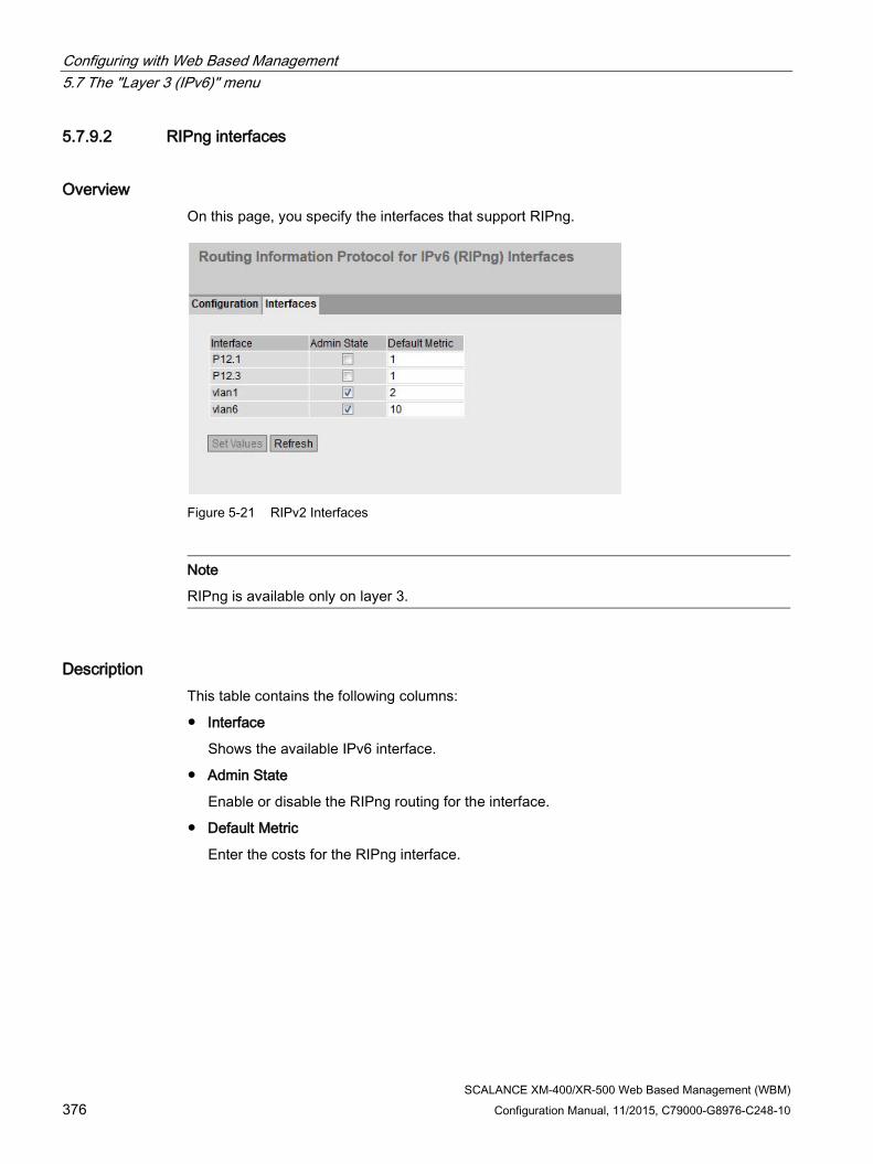
Configuring with Web Based Management 5.7 The "Layer 3 (IPv6)" menu
SCALANCE XM-400/XR-500 Web Based Management (WBM) 376 Configuration Manual, 11/2015, C79000-G8976-C248-10
5.7.9.2 RIPng interfaces
Overview On this page, you specify the interfaces that support RIPng.
Figure 5-21 RIPv2 Interfaces
Note
RIPng is available only on layer 3.
Description This table contains the following columns:
● Interface
Shows the available IPv6 interface.
● Admin State
Enable or disable the RIPng routing for the interface.
● Default Metric
Enter the costs for the RIPng interface.

Configuring with Web Based Management 5.8 The "Security" menu
SCALANCE XM-400/XR-500 Web Based Management (WBM) Configuration Manual, 11/2015, C79000-G8976-C248-10 377
5.8 The "Security" menu
5.8.1 User management
Overview of user management Access to the device is managed by configurable user settings. Set up users with a password for authentication. Assign a role with suitable rights to the users.
The authentication of users can either be performed locally by the device or by an external RADIUS server. You configure how the authentication is handled on the "Security > AAA > General" page.
Compatibility with predecessor versions With firmware version 5.1, user management was expanded by the RADIUS authorization mode "SiemensVSA". To ensure compatibility with firmware versions ≤ 5.0, the default setting was selected so that following a firmware update the earlier authentication mode "conventional" continues to be used.
Local logon The local logging on of users by the device runs as follows:
1. The user logs on with user name and password on the device.
2. The device checks whether an entry exists for the user.
→ If an entry exists, the user is logged in with the rights of the associated role.
→ If no corresponding entry exists, the user is denied access.
Login via an external RADIUS server RADIUS (Remote Authentication Dial-In User Service) is a protocol for authenticating and authorizing users by servers on which user data can be stored centrally.
Depending on the RADIUS authorization mode you have selected on the "Security > AAA > RADIUS Client" page, the device evaluates different information of the RADIUS server.

Configuring with Web Based Management 5.8 The "Security" menu
SCALANCE XM-400/XR-500 Web Based Management (WBM) 378 Configuration Manual, 11/2015, C79000-G8976-C248-10
RADIUS authorization mode "Standard"
If you have set the authorization mode "conventional", the authentication of users via a RADIUS server runs as follows:
1. The user logs on with user name and password on the device.
2. The device sends an authentication request with the login data to the RADIUS server.
3. The RADIUS server runs a check and signals the result back to the device.
– The RADIUS server reports a successful authentication and returns the value "Administrative User" to the device for the attribute "Service Type".
→ The user is logged in with administrator rights.
– The RADIUS server reports a successful authentication and returns a different or even no value to the device for the attribute "Service Type".
→ The user is logged in with read rights.
– The RADIUS server reports a failed authentication to the device:
→ The user is denied access.
RADIUS authorization mode "SiemensVSA"
Requirement
For the RADIUS authorization mode "Siemens VSA" the following needs to be set on the RADIUS server:
● Manufacturer code: 4196
● Attribute number: 1
● Attribute format: Character string (group name)
Procedure

Configuring with Web Based Management 5.8 The "Security" menu
SCALANCE XM-400/XR-500 Web Based Management (WBM) Configuration Manual, 11/2015, C79000-G8976-C248-10 379
If you have set the authorization mode "SiemensVSA", the authentication of users via a RADIUS server runs as follows:
1. The user logs on with user name and password on the device.
2. The device sends an authentication request with the login data to the RADIUS server.
3. The RADIUS server runs a check and signals the result back to the device.
Case A: The RADIUS server reports a successful authentication and returns the group assigned to the user to the device.
– The group is known on the device and the user is not entered in the table "External User Accounts"
→ The user is logged in with the rights of the assigned group.
– The group is known on the device and the user is entered in the table "External User Accounts"
→ The user is assigned the role with the higher rights and logged in with these rights.
– The group is not known on the device and the user is entered in the table "External User Accounts"
→ The user is logged in with the rights of the role linked to the user account.
– The group is not known on the device and the user is not entered in the table "External User Accounts"
→ The user is logged in with the rights of the role "Default".
Case B: The RADIUS server reports a successful authentication but does not return a group to the device.
– The user is entered in the table "External User Accounts":
→ The user is logged in with the rights of the linked role "".
– The user is not entered in the table "External User Accounts":
→ The user is logged in with the rights of the role "Default".
Case C: The RADIUS server reports a failed authentication to the device:
– The user is denied access.

Configuring with Web Based Management 5.8 The "Security" menu
SCALANCE XM-400/XR-500 Web Based Management (WBM) 380 Configuration Manual, 11/2015, C79000-G8976-C248-10
5.8.2 Users
5.8.2.1 Roles
Roles On this page, you create roles that are valid locally on the device.
Note
The values displayed depend on the rights of the logged-in user.
Note
You can create up to 28 additional roles.

Configuring with Web Based Management 5.8 The "Security" menu
SCALANCE XM-400/XR-500 Web Based Management (WBM) Configuration Manual, 11/2015, C79000-G8976-C248-10 381
Description The page contains the following:
● Role Name
Enter the name for the role. The name must meet the following conditions:
– It must be unique.
– It must be between 1 and 64 characters long.
Note
Role name cannot be changed
After creating a role, the name of the role can no longer be changed.
If a name of a role needs to be changed, the role must be deleted and a new role created.
The table contains the following columns:
● Select
Select the check box in the row to be deleted.
Note
Predefined roles and assigned roles cannot be deleted or modified.
● Role
Shows the name of the role.
● Function Right
Select the function rights of the role.
– 1
Users with this role can read device parameters but cannot change them.
– 15
Users with this role can both read and change device parameters.
Note Function right cannot be changed
If you have assigned a role, you can no longer change the function right of the role.
If you want to change the function right of a role, follow the steps outlined below: 1. Delete all assigned users. 2. Change the function right of the role: 3. Assign the role again.
● Description
Enter a description for the role. With predefined roles a description is displayed. The description text can be up to 100 characters long.

Configuring with Web Based Management 5.8 The "Security" menu
SCALANCE XM-400/XR-500 Web Based Management (WBM) 382 Configuration Manual, 11/2015, C79000-G8976-C248-10
Procedure Creating a role
1. Enter the name for the role.
2. Click the "Create" button.
3. Select the function rights of the role.
4. Enter a description of the role.
5. Click the "Set Values" button.
Deleting a role
1. Select the check box in the row to be deleted.
2. Click the "Delete" button. The entries are deleted and the page is updated.
5.8.2.2 Groups
User Groups On this page you link a group with a role.
In this example the group "Administrators" is linked to the "admin"role: The group is defined on a RADIUS server. The role is defined locally on the device. When a RADIUS server authenticates a user and assigns the user to the "Administrators" group, this user is given rights of the "admin" role.
Note
The values displayed depend on the rights of the logged-in user.
Note
You can create up to 32 groups.

Configuring with Web Based Management 5.8 The "Security" menu
SCALANCE XM-400/XR-500 Web Based Management (WBM) Configuration Manual, 11/2015, C79000-G8976-C248-10 383
Description The page contains the following:
● Group Name
Enter the name of the group. The name must match the group on the RADIUS server.
The name must meet the following conditions:
– It must be unique.
– It must be between 1 and 64 characters long.
The table contains the following columns:
● Select
Select the check box in the row to be deleted.
● Group
Shows the name of the group.
● Role
Select a role. Users who are authenticated with the linked group on the RADIUS server receive the rights of this role locally on the device.
You can choose between system-defined and self-defined roles, refer to the page "Security > Users > Roles.".
● Description
Enter a description for the link of the group.to a role. The description text can be up to 100 characters long.
Procedure Linking a group to a role.
1. Enter the name of a group.
2. Click the "Create" button.
3. Select a role.
4. Enter a description for the link of a group.to a role.
5. Click the "Set Values" button.
Deleting the link between a group and a role
1. Select the check box in the row to be deleted.
2. Click the "Delete" button. The entries are deleted and the page is updated.

Configuring with Web Based Management 5.8 The "Security" menu
SCALANCE XM-400/XR-500 Web Based Management (WBM) 384 Configuration Manual, 11/2015, C79000-G8976-C248-10
5.8.2.3 Local Users
Local users On this page, you create local users with the corresponding rights.
When you create or delete a local user this change is also made automatically in the table "External User Accounts". If you want to make change explicitly for the internal or external user table, use the CLI commands.
Note
The values displayed depend on the rights of the logged-in user.
Note
You can create up to 16 additional users.

Configuring with Web Based Management 5.8 The "Security" menu
SCALANCE XM-400/XR-500 Web Based Management (WBM) Configuration Manual, 11/2015, C79000-G8976-C248-10 385
Description The page contains the following:
● User Account
Enter the name for the user. The name must meet the following conditions:
– It must be unique.
– It must be between 1 and 250 characters long.
Note
User name cannot be changed
After creating a user, the user name can no longer be modified.
If a user name needs to be changed, the user must be deleted and a new user created.
● Password Policy
Shows which password policy is being used.
● Password
Enter the password for the user.
Note Password Policy: high
Note the following password policies: • Password length: at least 8 characters, maximum 128 characters • At least 1 uppercase letter • At least 1 special character • At least 1 number
● Password Confirmation
Enter the password again to confirm it.
● Role
Select a role.
You can choose between system-defined and self-defined roles, refer to the page "Security > Users > Roles.".
The table contains the following columns:
● Select
Select the check box in the row to be deleted.
Note
The preset users as well as logged in users cannot be deleted or changed.
● User Account
Shows the user name.

Configuring with Web Based Management 5.8 The "Security" menu
SCALANCE XM-400/XR-500 Web Based Management (WBM) 386 Configuration Manual, 11/2015, C79000-G8976-C248-10
● Role
Shows the role of the user.
● Description
Displays a description of the user account. The description text can be up to 100 characters long.
Procedure Creating users
1. Enter the name for the user.
2. Enter the password for the user.
3. Enter the password again to confirm it.
4. Select the role of the user.
5. Click the "Create" button.
6. Enter a description of the user.
7. Click the "Set Values" button.
Deleting users
1. Select the check box in the row to be deleted.
2. Click the "Delete" button. The entries are deleted and the page is updated.

Configuring with Web Based Management 5.8 The "Security" menu
SCALANCE XM-400/XR-500 Web Based Management (WBM) Configuration Manual, 11/2015, C79000-G8976-C248-10 387
5.8.3 Passwords
Configuration of the device passwords
Note
If you are logged in via a RADIUS server, you cannot change any passwords.
On this page, you can change passwords. If you are logged in with the right to change device parameters, you can change the passwords for all user accounts. If you are logged in with read rights, you can only change your own password.
Description of the displayed boxes ● Current User
Shows the user that is currently logged in.
● Current User Password
Enter the password for the currently logged in user.
● User Account
Select the user whose password you want to change.

Configuring with Web Based Management 5.8 The "Security" menu
SCALANCE XM-400/XR-500 Web Based Management (WBM) 388 Configuration Manual, 11/2015, C79000-G8976-C248-10
● New Password
Enter the new password for the selected user.
Note Password Policy: high
Note the following password policies: • Password length: at least 8 characters, maximum 128 characters • at least 1 uppercase letter • at least 1 special character • at least 1 number
● Password Confirmation
Enter the new password again to confirm it.
Procedure
Note
The factory settings for the passwords when the devices ship are as follows: • admin: admin • user: user
When you log in for the first time or following a "Restore Factory Defaults and Restart", with the preset user "admin" you will be prompted to change the password.
Note Changing the password in Trial mode
Even if you change the password in Trial mode, this change is saved immediately.
1. Enter the password for the currently logged in user in the "Current User Password" input box.
2. In the "User Account" drop-down list select the user whose password you want to change.
3. Enter the new password for the selected user in the "New Password" input box.
4. Repeat the new password in the "Password Confirmation" input box.
5. Click the "Set Values" button.

Configuring with Web Based Management 5.8 The "Security" menu
SCALANCE XM-400/XR-500 Web Based Management (WBM) Configuration Manual, 11/2015, C79000-G8976-C248-10 389
5.8.4 AAA
5.8.4.1 General
Login of network nodes The designation "AAA" stands for "Authentication, Authorization, Accounting". This feature is used to identify and allow network nodes, to make the corresponding services available to them and to specify the range of use.
On this page, you configure the login.
Description of the displayed boxes The page contains the following boxes:
Note
To be able to use the login authentication "RADIUS", "Local and RADIUS" or "RADIUS and fallback Local" a RADIUS server must be stored and configured for user authentication.
● Login Authentication Specify how the login is made:
– Local
The authentication must be made locally on the device.
– RADIUS
The authentication must be handled via a RADIUS server.
– Local and RADIUS
The authentication is possible both with the users that exist on the device (user name and password) and via a RADIUS server.
The user is first searched for in the local database. If the user does not exist there, a RADIUS request is sent.
– RADIUS and fallback local
The authentication must be handled via a RADIUS server.
A local authentication is performed only when the RADIUS server cannot be reached in the network.

Configuring with Web Based Management 5.8 The "Security" menu
SCALANCE XM-400/XR-500 Web Based Management (WBM) 390 Configuration Manual, 11/2015, C79000-G8976-C248-10
5.8.4.2 RADIUS Client
Authentication over an external server The concept of RADIUS is based on an external authentication server.
Each row of the table contains access data for one server. In the search order, the primary server is queried first. If the primary server cannot be reached, secondary servers are queried in the order in which they are entered.
If no server responds, there is no authentication.
Description of the displayed boxes The page contains the following boxes:
● RADIUS Authorization Mode
For the login authentication, the RADIUS authorization mode specifies how the rights are assigned to the user with a successful authentication.
– Conventional
In this mode the user is logged in with administrator rights if the server returns the value "Administrative User" to the device for the attribute "Service Type". In all other cases the user is logged in with read rights.
– SiemensVSA
In this mode the assignment of rights depends on whether and which group the server returns for the user and whether or not there is an entry for the user in the table "External User Accounts".

Configuring with Web Based Management 5.8 The "Security" menu
SCALANCE XM-400/XR-500 Web Based Management (WBM) Configuration Manual, 11/2015, C79000-G8976-C248-10 391
The table has the following columns:
● Select Select the row you want to delete.
● Auth. Server Type
Select the which authentication method the server will be used for.
– Login
The server is used only for the login authentication.
– 802.1X
The server is used only for the 802.1X authentication.
– Login & 802.1X
The server is used for both authentication procedures.
● RADIUS Server Address Enter the IPv4 address or the FQDN (Fully Qualified Domain Name) of the RADIUS server.
● Server Port Here, enter the input port on the RADIUS server. As default, input port 1812 is set. The range of values is 1 to 65535.
● Shared Secret Enter your access ID here. The range of values is 1...128 characters
● Shared Secret Conf. Enter your access ID again as confirmation.
● Max. Retrans.
Here, enter the maximum number of retries for an attempted request.
The initial connection attempt is repeated the number of times specified here before another configured RADIUS server is queried or the login counts as having failed. As default 3 retries are set, this means 4 connection attempts. The range of values is 1 to 254.
● Primary Server Using the options in the drop-down list, specify whether or not this server is the primary server. You can select one of the options "yes" or "no".
● Status With this check box, you can enable or disable the RADIUS server.
Note
You can configure a maximum of three servers on this page.

Configuring with Web Based Management 5.8 The "Security" menu
SCALANCE XM-400/XR-500 Web Based Management (WBM) 392 Configuration Manual, 11/2015, C79000-G8976-C248-10
Steps in configuration Entering a new server
1. Click the "Create" button. A new entry is generated in the table. The following default values are entered in the table:
– Auth. Server Type Login & 802.1X
– RADIUS Server Address: 0.0.0.0
– Server Port: 1812
– Max. Retrans.: 3
– Primary server: No
2. In the relevant row, enter the following data in the input boxes:
– Auth. Server Type Login & 802.1X
– RADIUS Server Address
– Server Port
– Shared Secret
– Shared Secret Conf.
– Max. Retrans.: 3
– Primary server: No
3. Click the "Set Values" button.
Repeat this procedure for every server you want to enter.
Modifying servers
1. In the relevant row, enter the following data in the input boxes:
– RADIUS Server Address
– Server Port
– Shared Secret
– Shared Secret Conf.
– Max. Retrans.
– Primary server
2. Click the "Set Values" button.
Repeat this procedure for every server whose entry you want to modify
Deleting servers
1. Click the check box in the first column before the row you want to delete to select the entry for deletion. Repeat this for all entries you want to delete.
2. Click the "Delete" button. The data is deleted from the memory of the device and the page is updated.

Configuring with Web Based Management 5.8 The "Security" menu
SCALANCE XM-400/XR-500 Web Based Management (WBM) Configuration Manual, 11/2015, C79000-G8976-C248-10 393
5.8.4.3 802.1x Authenticator
Setting up network access An end device can only access the network after the device has verified the login data of the device with the authentication server. Both the end device and the authentication server must support the EAP protocol (Extensive Authentication Protocol).
Enabling authentication for individual ports By enabling the relevant options , you specify for each port whether or not network access protection according to IEEE 802.1X is enabled on this port.
Figure 5-22 802.1x Authenticator - first part of the table

Configuring with Web Based Management 5.8 The "Security" menu
SCALANCE XM-400/XR-500 Web Based Management (WBM) 394 Configuration Manual, 11/2015, C79000-G8976-C248-10
Figure 5-23 802.1X Authenticator - second part of the table
Description of the displayed boxes The page contains the following boxes:
● MAC Authentication
Enable or disable MAC authentication for the device.
● Guest VLAN
Enable or disable the "Guest VLAN" function for the device.
Table 1 has the following columns:
● 1st column Shows that the settings are valid for all ports of table 2.
● 802.1X Auth. Control Select the required setting. If "No Change" is selected, the entry in table 2 remains unchanged.
● 802.1X Re-Authentication Select the required setting. If "No Change" is selected, the entry in table 2 remains unchanged.
● MAC Authentication Select the required setting. If "No Change" is selected, the entry in table 2 remains unchanged.

Configuring with Web Based Management 5.8 The "Security" menu
SCALANCE XM-400/XR-500 Web Based Management (WBM) Configuration Manual, 11/2015, C79000-G8976-C248-10 395
● RADIUS VLAN Assignment Allowed Select the required setting. If "No Change" is selected, the entry in table 2 remains unchanged.
● MAC Auth. Max Allowed Addresses Specify how many end devices can be connected to the port at the same time. If "No Change" is selected, the entry in table 2 remains unchanged.
● Guest VLAN Select the required setting. If "No Change" is selected, the entry in table 2 remains unchanged.
● Guest VLAN ID Select the required setting. If "No Change" is selected, the entry in table 2 remains unchanged.
● Guest VLAN Max Allowed Addresses Specify how many end devices are permitted in the guest VLAN at the same time. If "No Change" is selected, the entry in table 2 remains unchanged.
● Copy to table If you click the button, the settings are adopted for all ports of table 2.
Table 2 has the following columns:
● Port This column lists all the ports available on this device.
● 802.1X Auth. Control Specify the authentication of the port:
– Force Unauthorized
Data traffic via the port is blocked.
– Force Authorized
Data traffic via the port is allowed without any restrictions.
Default setting
– Auto
End devices are authenticated on the port with the "802.1X" method.
The data traffic via the port is permitted or blocked depending on the authentication result.
● 802.1X Re-Authentication Enable this option if you want reauthentication of an already authenticated end device to be repeated cyclically.
● MAC Authentication Enable this option if you want end devices to be authenticated with the "MAC Authentication" method.
Note
At the port level, you cannot enable "MAC Authentication" and "Guest VLAN" at the same time.

Configuring with Web Based Management 5.8 The "Security" menu
SCALANCE XM-400/XR-500 Web Based Management (WBM) 396 Configuration Manual, 11/2015, C79000-G8976-C248-10
● RADIUS VLAN Assignment Allowed The RADIUS server informs the IE switch of the VLAN to which the port will belong.
Enable this option if you want the information of the server to be taken into account. The port is then assigned to the corresponding VLAN.
If the option is disabled, the original VLAN configuration of the port is restored,
● MAC Auth. Max Allowed Addresses Enter how many end devices are allowed to be connected to the port at the same time.
● Guest VLAN Enable this option if you want the end device to be permitted in the "Guest VLAN" if authentication fails.
Note
At the port level, you cannot enable "MAC Authentication" and "Guest VLAN" at the same time.
● Guest VLAN ID Enter the VLAN ID of the guest VLANs.
● Guest VLAN Max Allowed Addresses Enter how many end devices are allowed in the guest VLAN at the same time.
● 802.1X Auth. Status Shows the status of the authentication of the port:
– Authorized
– Not Authorized
– Auto
● MAC Auth. Actual Allowed Addresses Shows the number of currently connected end devices.
● MAC Auth. Actual Blocked Addreses Shows the number of currently blocked end devices.
● Guest VLAN Actual Allowed Addresses Shows how many end devices are currently allowed in the guest VLAN.
Steps in configuration Enabling authentication for an individual port
1. Select the required options in the relevant row in table 2.
2. To apply the changes, click the "Set Values" button.
Enabling authentication for all ports
1. Select the required options in table 1.
2. Click the "Copy to table" button. The check box is enabled for all ports in table 2.
3. To apply the changes, click the "Set Values" button.

Configuring with Web Based Management 5.8 The "Security" menu
SCALANCE XM-400/XR-500 Web Based Management (WBM) Configuration Manual, 11/2015, C79000-G8976-C248-10 397
5.8.5 MAC ACL
5.8.5.1 Rules Configuration
Introduction On this page, you specify the access rules for the MAC-based Access Control List. Using the MAC-based ACL, you can specify whether frames of certain MAC addresses are forwarded or discarded.
Description of the displayed boxes The table has the following columns:
● Select Select the row you want to delete.
● Rule Number Shows the number of the ACL rule. If you click the "Create" button, a new row with a unique number is created.
● Source MAC Enter the unicast MAC address of the source.
● Dest. MAC Enter the unicast MAC address of the destination.
● Action Select whether the frame is forwarded or rejected when it corresponds to the ACL rule.
– Forward If the frame complies with the ACL rule, the frame is forwarded.
– Discard If the frame complies with the ACL rule, the frame is not forwarded.
● Ingress Interfaces
Shows a list of all ingress ports to which this rule applies.
● Egress Interfaces
Shows a list of all egress ports to which this rule applies.

Configuring with Web Based Management 5.8 The "Security" menu
SCALANCE XM-400/XR-500 Web Based Management (WBM) 398 Configuration Manual, 11/2015, C79000-G8976-C248-10
Note Entering the MAC addresses
If you enter the address "00:00:00:00:00:00" for the source and/or destination MAC address, the rule created in this way applies to all source or destination MAC addresses.
Steps in configuration 1. Click the "Create" button. A new row with a unique number (rule number) is created in the
table.
2. Enter the MAC address of the source in "Source MAC".
3. Enter the MAC address of the destination in "Dest MAC".
4. In the "Action" drop-down list select whether the frame is forwarded or rejected when it corresponds to the ACL rule.
5.8.5.2 Ingress Rules
Introduction On this page, you specify the ACL rule according to which incoming frames are filtered at a port.

Configuring with Web Based Management 5.8 The "Security" menu
SCALANCE XM-400/XR-500 Web Based Management (WBM) Configuration Manual, 11/2015, C79000-G8976-C248-10 399
Description of the displayed boxes The page contains the following boxes:
● Ports Select the required port from the drop-down list.
● Add Rule From the drop-down list, select the ACL rule that will be assigned to the port. You specify the ACL rules in the "Rules Configuration" tab.
● Add To permanently assign the ACL rule to the port, click the "Add" button. The configuration is shown in the table.
● Remove Rule From the "Remove rule" drop-down list, select the ACL rule to be deleted.
● Remove To remove the ACL rule from the port, click the "Remove" button.
The table has the following columns:
● Rule Order Shows the order of the ACL rules.
● Rule Number Shows the number of the ACL rule.
● Source MAC Shows the unicast MAC address of the source.
● Dest. MAC Shows the unicast MAC address of the destination.
● Action Shows the action.
– Forward If the frame complies with the ACL rule, the frame is forwarded.
– Discard If the frame complies with the ACL rule, the frame is not forwarded.
Steps in configuration Follow the steps below to assign an ACL rule to a port:
1. Select the port in the "Ports" drop-down list.
2. Select the ACL rule in the "Add Rule" drop-down list.
3. Click the "Add" button. A new entry is generated in the table.
Follow the steps below to remove an ACL rule from a port:
1. Select the port in the "Ports" drop-down list.
2. Select the ACL rule in the "Remove Rule" drop-down list.
3. Click the "Remove" button. The corresponding entry is removed in the table.

Configuring with Web Based Management 5.8 The "Security" menu
SCALANCE XM-400/XR-500 Web Based Management (WBM) 400 Configuration Manual, 11/2015, C79000-G8976-C248-10
5.8.5.3 Egress Rules
Introduction On this page, you specify the ACL rules according to which outgoing frames are filtered at a port.
Description of the displayed boxes The page contains the following boxes:
● Ports Select the required port from the drop-down list.
● Add Rule From the drop-down list, select the ACL rule that will be assigned to the port. You specify the ACL rule in the "Rules Configuration" tab.
● Add To permanently assign the ACL rule to the port, click the "Add" button. The configuration is shown in the table.
● Remove Rule From the "Remove rule" drop-down list, select the ACL rule to be deleted.
● Remove To remove the ACL rule from the port, click the "Remove" button.
The table has the following columns:
● Rule Order Shows the order of the ACL rules.
● Rule Number Shows the number of the ACL rule.
● Source MAC Shows the unicast MAC address of the source.

Configuring with Web Based Management 5.8 The "Security" menu
SCALANCE XM-400/XR-500 Web Based Management (WBM) Configuration Manual, 11/2015, C79000-G8976-C248-10 401
● Dest. MAC Shows the unicast MAC address of the destination.
● Action Shows the action.
– Forward If the frame complies with the ACL rule, the frame is forwarded.
– Discard. If the frame complies with the ACL rule, the frame is not forwarded.
Steps in configuration Follow the steps below to assign an ACL rule to a port:
1. Select the port in the "Ports" drop-down list.
2. Select the ACL rule in the "Add Rule" drop-down list.
3. Click the "Add" button. A new entry is generated in the table.
Follow the steps below to remove an ACL rule from a port:
1. Select the port in the "Ports" drop-down list.
2. Select the ACL rule in the "Remove Rule" drop-down list.
3. Click the "Remove" button. The corresponding entry is removed in the table.
5.8.6 IP ACL
5.8.6.1 Rules Configuration
Introduction On this page, you specify the rules for the IP-based Access Control List. Using the IP-based ACL, you can specify whether frames of certain IPv4 addresses are forwarded or discarded.

Configuring with Web Based Management 5.8 The "Security" menu
SCALANCE XM-400/XR-500 Web Based Management (WBM) 402 Configuration Manual, 11/2015, C79000-G8976-C248-10
Description of the displayed boxes The table has the following columns:
● Select Select the row you want to delete.
● Rule Number Shows the number of the ACL rule. If you click the "Create" button, a new row with a unique number is created.
● Source IP Enter the IPv4 address of the source.
● Source Subnet Mask Enter the subnet mask of the source.
● Dest. IP Enter the IPv4 address of the destination.
● Dest. Subnet Mask Enter the subnet mask of the destination.
● Action Select whether the frame is forwarded or rejected when it corresponds to the ACL rule.
– Forward If the frame complies with the ACL rule, the frame is forwarded.
– Discard If the frame complies with the ACL rule, the frame is not forwarded.
● Ingress Interfaces
Shows a list of all ingress interfaces to which this rule applies.
● Egress Interfaces
Shows a list of all egress interfaces to which this rule applies.
Note Subnet mask for individual hosts
If you create the rule for a single system (one IPv4 address), specify the subnet mask "255.255.255.255".
Steps in configuration 1. Click the "Create" button. A new row with a unique number (rule number) is created in the
table. 2. Enter the data of the source in "Source IP" and in "Source Subnet Mask". 3. Enter the data of the destination in "Dest. IP" and in "Dest. Subnet Mask". 4. In the "Action" drop-down list select whether the frame is forwarded or rejected when the
frame corresponds to the ACL rule. 5. On the "Protocol Configuration " tab, you specify the rules for protocols. 6. In the "Ingress Rules" and "Egress Rules", select how incoming and outgoing frames are
handled by a port.

Configuring with Web Based Management 5.8 The "Security" menu
SCALANCE XM-400/XR-500 Web Based Management (WBM) Configuration Manual, 11/2015, C79000-G8976-C248-10 403
5.8.6.2 Protocol Configuration On this page, you specify the rules for protocols.
Settings
Figure 5-24 IP ACL Protocol Configuration
The table has the following columns:
● Rule Number
Shows the number of the protocol rule. When you create a rule, a new row with a unique number is created.
● Protocol
Select the protocol for which this rule is valid.
● Protocol Number
Enter a protocol number to define further protocols.
This box can only be edited if you have set "Other Protocol" for the protocol .
● Source Port Min.
Enter the lowest possible port number of the source port.
This box can only be edited if you have set "TCP" or "UDP" for the protocol.
● Source Port Max.
Enter the highest possible port number of the source port.
This box can only be edited if you have set "TCP" or "UDP" for the protocol.
● Dest. Port Min.
Enter the lowest possible port number of the destination port.
This box can only be edited if you have set "TCP" or "UDP" for the protocol.
● Dest. Port Max.
Enter the highest possible port number of the destination port.
This box can only be edited if you have set "TCP" or "UDP" for the protocol.

Configuring with Web Based Management 5.8 The "Security" menu
SCALANCE XM-400/XR-500 Web Based Management (WBM) 404 Configuration Manual, 11/2015, C79000-G8976-C248-10
● Message Type
Enter a message type to decide the format of the message.
This box can only be edited if you have set "ICMP" for the protocol.
● Message Code
Enter a message code to specify the function of the message.
This box can only be edited if you have set "ICMP" for the protocol.
● DSCP
Enter a value for classifying the priority.
This box cannot be edited if you have set "ICMP" for the protocol.
5.8.6.3 Ingress Rules
Introduction On this page, you specify the ACL rules according to which incoming frames are handled by a port or VLAN.
Figure 5-25 IP ACL ingress rules - first part of the table

Configuring with Web Based Management 5.8 The "Security" menu
SCALANCE XM-400/XR-500 Web Based Management (WBM) Configuration Manual, 11/2015, C79000-G8976-C248-10 405
Figure 5-26 IP ACL ingress rules - second part of the table
Description of the displayed boxes The page contains the following boxes:
● Ports Select the required port from the drop-down list. a port or a VLAN interface. To select a VLAN interface, an IP interface must be configured.
Note
If you use a VLAN interface, the ACL rule applies to all ports that belong to the VLAN.
● Add Rule From the drop-down list, select the ACL rule that will be assigned to the port. You specify the ACL rules in the "Rules Configuration" tab.
● Add To permanently assign the ACL rule to the port, click the "Add" button. The configuration is shown in the table.
● Remove Rule From the "Remove rule" drop-down list, select the ACL rule to be deleted.
● Remove To remove the ACL rule from the port, click the "Remove" button.
The table has the following columns:
● Rule Order Shows the order of the ACL rules.
● Rule Number Shows the number of the ACL rule. If you click the "Create" button, a new row with a unique number is created.

Configuring with Web Based Management 5.8 The "Security" menu
SCALANCE XM-400/XR-500 Web Based Management (WBM) 406 Configuration Manual, 11/2015, C79000-G8976-C248-10
● Protocol
Shows the protocol for which this rule is valid.
● Protocol Number
Shows the protocol number.
● Source IP Shows the IPv4 address of the source.
● Source Subnet Mask Shows the subnet mask of the source.
● Dest IP Shows the IP address of the destination.
● Dest. Subnet Mask Shows the subnet mask of the destination.
● Action Select whether the frame is forwarded or rejected when it corresponds to the ACL rule.
– Forward If the frame complies with the ACL rule, the frame is forwarded.
– Discard If the frame complies with the ACL rule, the frame is not forwarded.
● Source Port Min.
Shows the lowest possible port number of the source port.
● Source Port Max.
Shows the highest possible port number of the source port.
● Dest. Port Min.
Shows the lowest possible port number of the destination port.
● Dest. Port Max.
Shows the highest possible port number of the destination port.
● Message Type
Shows a message type to decide the format of the message.
● Message Code
Shows a message code to specify the function of the message.
● DSCP
Shows a value for classifying the priority.

Configuring with Web Based Management 5.8 The "Security" menu
SCALANCE XM-400/XR-500 Web Based Management (WBM) Configuration Manual, 11/2015, C79000-G8976-C248-10 407
Steps in configuration Follow the steps below to assign an ACL rule to a port or a VLAN interface:
1. Select the port or the VLAN interface in the "Ports" drop-down list.
2. Select the ACL rule in the "Add Rule" drop-down list.
3. Click the "Add" button. A new entry is generated in the table.
Follow the steps below to assign an ACL rule to a port or a VLAN interface:
1. Select the port or the VLAN interface in the "Ports" drop-down list.
2. Select the ACL rule in the "Remove Rule" drop-down list.
3. Click the "Remove" button. The corresponding entry is deleted.
5.8.6.4 Egress Rules
Introduction On this page, you specify the ACL rule according to which outgoing frames are handled by a port.
Figure 5-27 IP ACL egress rules - first part of the table

Configuring with Web Based Management 5.8 The "Security" menu
SCALANCE XM-400/XR-500 Web Based Management (WBM) 408 Configuration Manual, 11/2015, C79000-G8976-C248-10
Figure 5-28 IP ACL egress rules - second part of the table
Description of the displayed boxes The page contains the following boxes:
● Ports Select the required port from the drop-down list. a port or a VLAN interface. To select a VLAN interface, an IP interface must be configured.
Note
If you use a VLAN interface, the ACL rule applies to all ports that belong to the VLAN.
● Add Rule From the drop-down list, select the ACL rule that will be assigned to the port. You specify the ACL rules in the "Rules Configuration" tab.
● Add To permanently assign the ACL rule to the port, click the "Add" button. The configuration is shown in the table.
● Remove Rule From the "Remove rule" drop-down list, select the ACL rule to be deleted.
● Remove To remove the ACL rule from the port, click the "Remove" button.
The table has the following columns:
● Rule Order Shows the order of the ACL rules.
● Rule Number Shows the number of the ACL rule. If you click the "Create" button, a new row with a unique number is created.

Configuring with Web Based Management 5.8 The "Security" menu
SCALANCE XM-400/XR-500 Web Based Management (WBM) Configuration Manual, 11/2015, C79000-G8976-C248-10 409
● Protocol
Shows the protocol for which this rule is valid.
● Protocol Number
Shows the protocol number.
● Source IP Shows the IPv4 address of the source.
● Source Subnet Mask Shows the subnet mask of the source.
● Dest IP Shows the IP address of the destination.
● Dest. Subnet Mask Shows the subnet mask of the destination.
● Action Select whether the frame is forwarded or rejected when it corresponds to the ACL rule.
– Forward If the frame complies with the ACL rule, the frame is forwarded.
– Discard If the frame complies with the ACL rule, the frame is not forwarded.
● Source Port Min.
Shows the lowest possible port number of the source port.
● Source Port Max.
Shows the highest possible port number of the source port.
● Dest. Port Min.
Shows the lowest possible port number of the destination port.
● Dest. Port Max.
Shows the highest possible port number of the destination port.
● Message Type
Shows a message type to decide the format of the message.
● Message Code
Shows a message code to specify the function of the message.
● DSCP
Shows a value for classifying the priority.

Configuring with Web Based Management 5.8 The "Security" menu
SCALANCE XM-400/XR-500 Web Based Management (WBM) 410 Configuration Manual, 11/2015, C79000-G8976-C248-10
Steps in configuration Follow the steps below to assign an ACL rule to a port or a VLAN interface:
1. Select the port or the VLAN interface in the "Ports" drop-down list.
2. Select the ACL rule in the "Add Rule" drop-down list.
3. Click the "Add" button. A new entry is generated in the table.
Follow the steps below to assign an ACL rule to a port or a VLAN interface:
1. Select the port or the VLAN interface in the "Ports" drop-down list.
2. Select the ACL rule in the "Remove Rule" drop-down list.
3. Click the "Remove" button. The corresponding entry is deleted.
5.8.7 Management ACL
Description of configuration On this page, you can increase the security of your device. To specify which station with which IPv4 address is allowed to access your device, configure the IPv4 address or an entire address range.
You can select the protocols and the ports of the station with which it is allowed to access the device. You define the VLAN in which the station may be located. This ensures that only certain stations within a VLAN have access to the device.
Description of the displayed boxes
Note If you enable this function, note the following
A bad configuration on the "Management Access Control List" page can result in you being unable to access the device. You should therefore configure an access rule that allows access to the management before you enable the function.

Configuring with Web Based Management 5.8 The "Security" menu
SCALANCE XM-400/XR-500 Web Based Management (WBM) Configuration Manual, 11/2015, C79000-G8976-C248-10 411
The page contains the following boxes:
● Management ACL Enable or disable access control to the management of the IE switch.
As default, the function is disabled.
Note
If the function is disabled, there is unrestricted access to the management of the IE switch. The configured access rules are only taken into account when the function is enabled.
● IP Address Enter the IPv4 address or the network address from which the rule will apply. If you use the IPv4 address 0.0.0.0, the settings apply to all IPv4 addresses.
● Subnet Mask Enter the subnet mask. The subnet mask 255.255.255.255 is for a specific IPv4 address. If you want to allow a subnet, for example a C subnet, enter 255.255.255.0. The subnet mask 0.0.0.0 applies to all subnets.
The table has the following columns:
● Select Select the row you want to delete.
● Rule Order Shows the order of the ACL rules.
● IP address Shows the IPv4 address.
● Subnet Mask Shows the subnet mask.
● VLANs Allowed Enter the number of the VLAN in which the device is located. The station can only access the device if it is located in this configured VLAN. If this input box remains empty, there is no restriction relating to the VLANs.
● Out-Band Specify whether or not the IPv4 address can access the switch via the out-band port.
● SNMP Specify whether the station (or the IPv4 address) can access the device using the SNMP protocol.
● TELNET Specify whether the station (or the IPv4 address) can access the device using the TELNET protocol.
● HTTP Specify whether the station (or the IPv4 address) can access the device using the HTTP protocol.
● HTTPS Specify whether the station (or the IPv4 address) can access the switch using the HTTPS protocol.

Configuring with Web Based Management 5.8 The "Security" menu
SCALANCE XM-400/XR-500 Web Based Management (WBM) 412 Configuration Manual, 11/2015, C79000-G8976-C248-10
● SSH Specify whether the station (or the IPv4 address) can access the switch using the SSH protocol.
● Px.y Specify whether the station (or the IPv4 address) can access this device via this port (slot.port).
Steps in configuration Changing the entry
1. Configure the data of the entry you want to modify.
2. Click the "Set Values" button to transfer the changes to the device.
Creating a new entry
Note
Note that a bad configuration may mean that you can no longer access the device.
You can then only remedy this by resetting the device to the factory defaults and then reconfiguring.
1. In the "IP Address" input box, enter the IPv4 address of the device and in the "Subnet Mask" input box the corresponding subnet mask.
2. Click the "Create" button to create a new row in the table.
3. Configure the entries of the new row.
4. Click the "Set Values" button to transfer the new entry to the device.
Deleting entries
1. Select the check box in the row to be deleted.
2. Repeat this procedure for every entry you want to delete.
3. Click the "Remove" button. The entries are deleted and the page is updated.
SCALANCE XM-400/XR-500 Web Based Management (WBM) Configuration Manual, 11/2015, C79000-G8976-C248-10 413
Troubleshooting/FAQ 6 6.1 Firmware update via WBM or CLI not possible
Cause If there is a power failure during the firmware update, it is possible that the IE switch is no longer accessible using Web Based Management or the Command Line Interface.
Solution If the IE switch cannot be reached using WBM or CLI, you can download the firmware to your IE switch using TFTP.
Follow the steps below to load new firmware using TFTP:
1. Turn off the power to the IE switch.
2. Press the Reset button and reconnect the power to the IE switch while holding down the button.
3. Hold down the button until the red fault LED (F) starts to flash after approximately 30 seconds.
4. Release the button.
The bootloader waits in this state for a new firmware file that you can download by TFTP.
5. Connect a PC via the Ethernet interface with the out-band interface of the IE switch.
6. Assign an IP address to the IE switch with the Primary Setup Tool.
7. In the command prompt, change to the directory where the file with the new firmware is located and then execute the command "tftp -i <ip address> PUT <firmware>". As an alternative, you can use a different TFTP client.
Result The firmware is transferred to the IE switch.
Note
Please note that the transfer of the firmware can take several minutes. During the transmission, the red error LED (F) flashes.
Once the firmware has been transferred completely to the IE switch, the IE switch is restarted automatically.

Troubleshooting/FAQ 6.1 Firmware update via WBM or CLI not possible
SCALANCE XM-400/XR-500 Web Based Management (WBM) 414 Configuration Manual, 11/2015, C79000-G8976-C248-10

SCALANCE XM-400/XR-500 Web Based Management (WBM) Configuration Manual, 11/2015, C79000-G8976-C248-10 415
Index
1 1588, 289
A Access control, 273, 275
Automatic learning, 275 ACL, 275, 410 Aging
Dynamic MAC Aging, 241 Aging time, 280, 285 Alarm events, 149 Authentication, 158, 393
B Bridge, 249
Bridge priority, 249 Root bridge, 249
Bridge Max Age, 250 Bridge Max Hop Count, 250 Broadcast, 287 Button, 177
C Cable test, 205 Class of Service, 213 Collisions, 93 Combo port, 14 Combo Port Media Type, 182, 187 Configuration mode, 130 CoS, 213
Traffic queue, 214 CoS (Class of Service), 35 C-PLUG
Formatting, 196 Saving the configuration, 196
C-PLUG / KEY-PLUG, 16 CRC, 93
D DCP server, 129, 266
DHCP Client, 151
DHCPv4 Relay Agent General settings, 354
DHCPv6 Client, 343 PD Sub Client, 345 Prefix delegation, 343, 345
DNS client, 134 DSCP, 215 DST
Daylight saving time, 162, 164
E E-Mail function, 149
Alarm events, 149 Line monitoring, 149
Error status, 76 Ethernet Statistics
Frame Type, 91 History, 94 Interface statistics, 89 Packet Error, 92 Packet Size, 90
Event log table, 74 Events
Log Table, 74
F Fault monitoring
Connection status change, 191 Redundancy, 193
Filter Filter configuration, 273
Forward Delay, 250 Fragments, 93
G Geographic coordinates, 132 Glossary, 11 GMRP, 282 Groups, 382 GVRP, 223

Index
SCALANCE XM-400/XR-500 Web Based Management (WBM) 416 Configuration Manual, 11/2015, C79000-G8976-C248-10
H Hardware Revision, 71 Hello time, 250 HRP, 245 HTTP
Load/save, 137 HTTPS
Server, 128
I IEEE 1588, 289 IGMP, 280 Information
ARP table, 72 Groups, 127 IPv6 Neighbor Table, 73 LLDP, 98 Log Table, 74 Ring redundancy, 85, 87 Role, 126 Security, 123, 125 SNMP, 121, 122 Spanning Tree, 77 Start page, 64 Versions, 69
IPv4 OSPF, 40 VRRP, 39 VRRPv3, 39
IPv4 address, 133 IPv4 routing
OSPFv2 interfaces, 102 OSPFv2 LSDB (information), 107 OSPFv2 neighbors, 103 OSPFv2 Virtual Neighbors, 105 RIPv2 Statistics, 108 Routing table, 101
IPv6, 14 Notation, 28 OSPFv3, 44 VRRPv3, 39
IPv6 addresses, 14 IPv6 routing
OSPFv3 AS-Scope LSDB, 116, 117 OSPFv3 Interfaces, 110 OSPFv3 Link-Scope LSDB, 119 OSPFv3 Neighbors, 112 OSPFv3 virtual neighbors, 114 Routing table, 109, 120 Static routes, 346
J Jabbers, 93
K KEY-PLUG, 194, 198, 198
Formatting, 196
L LACP, 263 Layer 2, 209
MLD (IPv6), 286 Layer 3, 198, 198 Layer 3 (IPv4), 295
Configuration, 295 Layer 3 (IPv6), 340
Configuration, 340 Line monitoring, 149 LLDP, 98, 268 Local users, 384 Location, 132 Logging on
via HTTP, 61 via HTTPS, 61
Logout Automatic, 176
Loop, 261 Loop detection, 261, 261
M MAC ACL, 397, 398
Configuration, 398, 400 Maintenance data, 70 Management ACL, 410 Manufacturer, 70 Manufacturer ID, 71 Mirroring, 231
General, 232 IP Flow, 240 MAC Flow, 239 Port, 237 VLAN, 238
MLD, 285 MSTP, 248, 255
Port, 251 Port parameters, 256
MSTP instance, 256, 257 Multicast, 277

Index
SCALANCE XM-400/XR-500 Web Based Management (WBM) Configuration Manual, 11/2015, C79000-G8976-C248-10 417
Multiple Spanning Tree, 251, 255
N Near Field Communication, 130 Negotiation, 182 NFC, 130 NTP, 277
Client, 171
O Order ID, 71 OSPF
Areas, 40 Link State Advertisement, 40 Router, 40 Router status, 40
OSPF (IPv4) Area range, 327 Areas, 326 Configuration, 324 Interface authentication, 331 OSPFv2 interfaces, 102 OSPFv2 Interfaces, 329 OSPFv2 LSDB (information), 107 OSPFv2 neighbors, 103 OSPFv2 Virtual Neighbors, 105 Virtual link authentication, 335 Virtual Links, 333
OSPF (IPv6) Area Range, 368 Areas, 366, 366 OSPFv3 AS-Scope LSDB, 116, 117 OSPFv3 interfaces, 370 OSPFv3 Interfaces, 110 OSPFv3 Link-Scope LSDB, 119 OSPFv3 Neighbors, 112 OSPFv3 virtual neighbors, 114 Virtual Links, 372
OSPFv3 Configuration, 364
Oversize, 93
P Packet error statistics, 92 Password, 387 Ping, 199
PLUG, 198, 198 C-PLUG, (C-PLUG) KEY-PLUG, (KEY-PLUG)
PNIO, 193 PoE, 200, 202
Port, 202 point-to-point, 48 Port, 185
Port configuration, 181, 189 Port configuration, 185, 189 Port diagnostics
Cable test, 205 SFP diagnostics, 207
Power over Ethernet, 18, 200 Port, 202
Power supply Monitoring, 189
Prioritization, 216 Priority, 216, 250 PROFINET IO, 193 PST tool, 266 PTP, 289, 290, 290
General, 290 Port, 290 Transparent clock, 290
Q QoS, 216
R RADIUS, 390 Rate control, 218 Reboot, 136 Redundancy, 243, 245 Redundancy methods
HRP, 49 Redundant networks, 249 Reset, 136 RFC
RFC 1518, 23 Ring redundancy, 243
HRP, 211, 243 MRP, 211, 243 Ring ports, 243 Standby, 245
RIP (IPv4) RIPv2 Statistics, 108
RIPng Configuration, 375

Index
SCALANCE XM-400/XR-500 Web Based Management (WBM) 418 Configuration Manual, 11/2015, C79000-G8976-C248-10
Interfaces, 376 RIPng Statistics, 120
RIPv2 Configuration, 337 Interfaces, 338
RMON History, 293 Statistics, 292
Roles, 380 Root Max Age, 250 Route Map, 302, 348 Route maps, 302, 348 Routing, 38, 38, 300
IPv4 routing table, 101 IPv6 routing table, 109 Static IPv4 routes, 300 Static routes, 38, 38 VRRP, 38
RSTP, 248 Rule, 397, 398, 401
Configuration, 401 Egress, 400, 401 Ingress, 398, 401 IP ACL, 401
S Scope of the manual, 9 Security settings, 155 Select/Set button, 177 Serial number, 71 SFP diagnostics, 207 SHA algorithm, 155 SIMATIC NET glossary, 11 SMTP
Client, 129 SNMP, 36, 129, 152, 155
Groups, 155 Overview, 121 SNMPv1, 36 SNMPv2c, 36 SNMPv3, 36 Trap, 154 Users, 157
Software version, 71 Spanning tree, 248
MSTP, 248 Passive listening, 259 RSTP, 248
Spanning Tree Information, 77 Rapid Spanning Tree, 48
SSH Server, 128
Standby, 245 Standby redundancy, 57 Start page, 64 Static routes
IPv6 routes, 346 STEP 7, 266 STP, 248 Subnet mask, 23 Subnets
Configuration (IPv4), 299 Configuration (IPv6), 341 Connected Subnets (IPv6), 341 Overview (IPv4), 296
Syslog, 179 Client, 129
System Configuration, 128 General information, 131
System event log Agent, 179
System events Configuration, 145 Severity filter, 148
T Telnet
Server, 128 TFTP
Load/save, 141 Time, 129 Time of day
Manual setting, 160 Precision Time Protocol, 174 PTP Client, 174 SIMATIC Time Client, 173 SNTP (Simple Network Time Protocol), 168 System time, 160 Time zone, 170 Time-of-day synchronization, 168 UTC time, 170
Time setting, 129 Trust Mode, 216
U Undersize, 93 User Groups, 382

Index
SCALANCE XM-400/XR-500 Web Based Management (WBM) Configuration Manual, 11/2015, C79000-G8976-C248-10 419
V VLAN, 33, 227
Group, 227 Port VID, 226 Priority, 226 Tag, 226 VLAN ID, 35 VLAN tag, 34
VRRP Backup router, 39 Master router, 39 Virtual router, 39 VRRP address configuration (IPv4), 316 VRRP address overview (IPv4), 315 VRRP addresses overview (IPv4), 322 VRRP configuration (IPv4), 314 VRRP router, 39 VRRP routers (IPv4), 311, 317, 358 VRRP statistics, 80 VRRPv3 address configuration (IPv6), 363 VRRPv3 Addresses Configuration (IPv4), 323 VRRPv3 addresses overview (IPv6), 362 VRRPv3 Configuration (IPv4), 320 VRRPv3 Configuration (IPv6), 360
VRRPv3 VRRPv3 Statistics, 83
W Web Based Management, 59
Requirement, 59

Index
SCALANCE XM-400/XR-500 Web Based Management (WBM) 420 Configuration Manual, 11/2015, C79000-G8976-C248-10