SC-T4 Instruction Manual - OPTEX · Transmitter SC-T4. All of this instruction manual must be read...
14
SC-T4 Thank you very much for purchasing OPTEX Transmitter SC-T4. All of this instruction manual must be read before operation of the Transmitter SC-T4, for safe and proper operation. This instruction manual should be kept for future reference such as maintenance. Transmitter Instruction Manual 2006.8 59-1362-0 For more information on OPTEX products, contact your dealer or visit our website listed below; OPTEX CO., LTD. 5-8-12 Ogoto Otsu Shiga 520-0101 Japan tel : +81-77-579-8690 fax : +81-77-579-7120 E-mail : [email protected] website : http://www.optex.co.jp/env/ Distributed by
Transcript of SC-T4 Instruction Manual - OPTEX · Transmitter SC-T4. All of this instruction manual must be read...

SC-T4Thank you very much for purchasing OPTEX Transmitter SC-T4.All of this instruction manual must be read before operation of the Transmitter SC-T4, for safe and proper operation.
This instruction manual should be kept for future reference such as maintenance.
TransmitterInstruction Manual
2006.8 59-1362-0
For more information on OPTEX products, contact your dealer or visit our website listed below;
OPTEX CO., LTD.5-8-12 Ogoto Otsu Shiga 520-0101 Japantel : +81-77-579-8690fax : +81-77-579-7120E-mail : [email protected] : http://www.optex.co.jp/env/
Distributed by

The Contents of Packaging
Transmitter
Instruction Manual20 Y-terminal
Mounting Bracket
2 Transmitter Fixing Screw
In the unlikely event that there are any missing components or defects, please contact your dealer.
SC-T4Thank you very much for purchasing OPTEX Transmitter SC-T4.All of this instruction manual must be read before operation of the Transmitter SC-T4, for safe and proper operation.
This instruction manual should be kept for future reference such as maintenance.
TransmitterInstruction Manual
0
Please thoroughly read the "For safe use" before using the SC-T4
properly.
Because these precautions are related to failure or malfunction,
observe the precautions for use without fail.
In order to use the SC-T4 properly, observe the following precautions.
Precautions which are the cause of failure:
The SC-T4 is used exclusively to SS Checker (Detector). Accordingly, do not connect other equipment.
●Precautions which are the cause of failure ●Precautions related to measurement
・Do not disassemble or modify the Transmitter. Disassembly or modification may cause fire or an electric shock because there are high-voltage parts inside the Transmitter.
・Turn off the Power immediately in the unlikely event that there occur any abnormalities such as smoke or abnormal noise. Otherwise it may cause fire or an electric shock.
[Be sure to read this instruction manual in order to use the Transmitter SC-T4 properly.]
1 For safe use
" " denotes "Prohibited action", and " " denotes "Required action".
Power (OFF)
1

2 3
・Be sure to use the power supply of 100 to 240 VAC. Otherwise it may cause fire or electric shock.
・Do not wipe the Transmitter with solvent. It may cause failure.・To clean the Transmitter, first wipe
away lightly with a clean soft cloth damped by diluted mild detergent solution and then wipe off moisture with a dry clean soft cloth.
100 to 240 VACOrganic
Solvent
Thinneretc.
・There are high voltage parts inside the Transmitter. Failure to observe this precaution may cause fire or an electric shock. ・Do not give a strong shock to the
Transmitter.
・Do not press the CLEAN button, while the SS Checker (Detector) is in the air.
・Make sure that the Cover is locked without fail. Otherwise, protective structure may not function adequately.
Keep the Power off during installation and wiring operations.
Precautions which are the cause of failure: " " denotes "Prohibited action", and " " denotes "Required action".
・Use Cable Clamps attached to the transmitter for wiring. When the piping are directly connected with the transmitter, take a corrective action such as caulking against intrusion of gas because corrosive gas is in danger of intruding through the piping, etc. into the Transmitter.
・Do not bind the signal output cable with the power cable or do not put them in the one Cable Clamp.
・Install the transmitter with attached Mounting Bracket.
・Install the transmitter at a place ventilating well and avoiding direct sunlight.

4 5
Minus Indicator
Signal Output Response Time IndicatorDuring Signal Output Response Time setting: Blinking
SPAN IndicatorDuring Span Adjustment: BlinkingDuring Signal Output (4mA) Adjustment: OnDuring Signal Output (20mA) Adjustment: Blinking
ZERO IndicatorDuring ZERO Adjustment: BlinkingDuring Signal Output (4mA) Adjustment: BlinkingDuring Signal Output (20mA) Adjustment: On
Transmitter
Operation panel
Display
2 External Features
Cover
Cable Clamps
Key Hook
Lock Lever
Power SwitchCircuit BreakersTerminal Block
Operation Buttons
Display
Terminal Cover
Alarm Level Indicator (Green)Alarm Timer Indicator (Green)Warning Indicator (Red)
How to open the Cover
How to close the Cover
・Make sure that the Cover is locked without fail. Otherwise, protective structure may not function adequately.
Cover Opening & Closing Procedure
1. Slide up the Lock Lever. 2. Pull the Cover.
1. Close the Cover securely. 2. Slide down the Lock Lever until it stops.
CAUTION:

6 7
3 Installation
Fit the Mounting Bracket attached to the Transmitter with the Fitting Screws.
1 Install the Mounting Bracket on the wall and so forth. For mounting pitch, refer to the Fig. to the right.
Installation1
125m
m
186mm(Mounting Hole Φ9)
・ Install the Transmitter at a place ventilating well and avoiding direct sunlight.・ Install the Transmitter with Mounting Bracket.・ Close the Cover securely after installation is completed.
CAUTION:
・If there is a projection on the mounting surface, separate 40 mm or more from the upper Mounting Holes of the Mounting Bracket (See Fig. to the right).
40 mm or more from the center of the upper mounting holes
CAUTION:
2
・ Make sure that the Circuit Breaker is normal (OFF) position (Refer to [8] Troubleshooting).
Wiring
① ~ ⑳ ・ Compatible cable diameter with the Cable Clamps is 6 ~ 8 mm.
① ~ ⑦ ・ Use a shielded cable with nominal sectional area of 0.2 ~ 1.25 mm2 for the Detector Cable.
・ For extension of the Detector Cable, refer to [3] Detector Cable Extension. Use a device such as a Pull-box if necessary.
⑨ ~ ⑩ ・ Use a shielded cable with nominal sectional area of 0.75 to 1.25 mm2 for a Signal Output Cable.
・ For connection to the Signal Output terminal, load resistance should be 300 Ω Max (including wiring resistance).
⑪ ~ ⑯ ・ For connection to the Self Checking Relay Output terminal and Alarm Relay Output terminal, load resistance should be 240 VAC and 1A Max.
Although a protective circuit is built in to prevent from overcurrent due to thunderbolt, it is recommended to use fuses with rated current of 2A Max for the purpose of improvement of safety.
⑱ ・ Carry out grounding work.
⑲ ~ ⑳ ・ Use a cross-linked polyethylene insulating vinyl sheath cable with nominal sectional area of 0.75 to 1.25 mm2 for the power cable.
2
・Keep the Power off during wiring operations. Otherwise it may cause fire or an electric shock.・Wire the Power Cable, at the end of wiring operation.
CAUTION:
1 2 3 4 5 6 7 8 9 10 11 12 13 14 15 16 17 18 19 20
F.G.
Spare
Spare
Calibration Signal Output
Alarm Relay
Alarm Relay
Alarm Relay
Self Cheking Relay
Self Cheking Relay
Self Cheking Relay
Self Checking Input
Analog Signal Input
Analog Signal Output
Analog Signal Output
Analog Signal Input
Power Supply
Power Supply
12V Power Supply
12V Ground
Shield Line
(Blue)(Brown)(Black)(White)(Green) (Red)
COM NCNOCOM NCNO- +- +- +
Control Paneletc.Detector AC100 240V
50/60HzRecorderetc.
Self CheckingRelay Output
AlarmRelay Output
4-20mA
~
Controller Terminal Block
Reference:
・When the Detector is in the air, analog (4-20mA) signal output becomes approximately 6mA,

8 9
3
Nominal sectional area0.2 [mm2]
0.3 [mm2]
0.5 [mm2]
0.75 [mm2]
Max. cable length X[m]
10 [m]
20 [m]
40 [m]
50 [m]
The standard Detector Cable is 10m. The Detector Cable shall be extended by referring to the Table below. Use a device such as a Pull-box if necessary.
Extension of Detector Cable
Detector Cable length X[m]
Pull-box, etc.
The ENT button saves the numerical values entered and terminate the setting change operation.
Enter a numerical value (0, 1, 2, ..., 9) into the selected digit using the upper and lower arrow buttons . button increases a numeric value and button decreases the value.
Press the right and left arrow buttons simultaneously to carry out Fine Adjustment of Signal Output Low Limit (4mA).
Press the upper and lower arrow buttons simultaneously to carry out Fine Adjustment of Signal Output High Limit (20mA).
Move the digit to be entered using the right and left arrow buttons (0.1 digit 1 digit 10 digit 100 digit). At this time, the selected digit blinks.
The CAL button carries out calibration. Press the calibration button for 2 seconds or more to carry out calibration.
The MODE button makes sure of each setting. To change the setting value, select an item and then keep pressing the MODE button for 2 seconds or more.
The CLEAN button wipes the Detector Windows. To wipe the Detector Windows, press the CLEAN button for 2 seconds or more.
The CANCEL button cancels the setting change operation and return to the condition prior to change.
Operation Panel4

10 11
Operation5
2
Calibration
Each setting
※ Air bubbles on the Detector Windows can be removed by wiping.
Pip
1
Be sure to carry out calibration according to the following procedure before using the SC-T4.
4 When pressing the CAL button, "CAL" is displayed. "CAL" blinks during calibration.
3 After accustoming the Detector to water temperature for 5 minutes or so, make sure that air bubbles are not attached on the Detector Windows and press for 2 seconds or more.
5 When calibration is completed, the operation panel blips twice and the Display turns into normal measurements indication.
2 Immerse the Detector in distilled water or ion-exchange water.
1 Clean the Detector and the Detector Windows.
Every time the MODE button is pressed, the Display is changed into each setting. To change the setting value, select the item and then press for 2 seconds or more.
Factory setting and setting range are as shown in the Table below.
Alarm LevelAlarm TimerSignal Output Response Time
Factory settingOFFOFFOFF
Setting range1 ~ Span-Adjusted value
1 ~ 120 minute1 ~ 120 second
●Every time the MODE button is pressed, the display is changed as follows:
Fine Adjustment of High Limit 20mA
Fine Adjustment of Low Limit 4mA
Signal Output Response Time
Alarm Timer
Alarm Level
Span-Adjustment
0 (ZERO)-Adjustment
Measurements Indication
※The Detector Selection is fixed.
Ex: The measurement value : 50.0 mg/l
The Detector Selection
Ex: Signal Output Response Time : 10 seconds
Ex: Alarm Timer : 60 minutes
Ex: Alarm Level : 125 mg/l

12 13
3
Reference ・While pressing buttons, the values displayed are continuously changed.
・ Before making the 0-Adjustment, be sure to clean the Detector Windows.・ Before making the 0-Adjustment, be sure to carry out calibration.・ After making the 0-Adjustment, be sure to make the Span-Adjustment.
0 (ZERO) / Span - Adjustments
CAUTION:
Be sure to carry out calibration before setting these operations.
Notice; Keep covering one of the Detector Windows completely during the operation
Notice; Place the Detector in distilled water or ion-exchange water during the operation
4
3 After cleaning the Detector Windows, immerse the Detector in distilled water or ion-exchange water.
5
7 Cover one of the Detector Windows completely for 30 seconds or more.
6
2 Press and select the 0-Adjustment.
1 Wire all cable including the Detector.
After accustoming the Detector to water temperature for 5 minutes or so, make sure that air bubbles are not attached on the Detector Windows. And press for 2 seconds or more, "ZERO" blinks on the Display.
7 9-
3 5-
When the Display is not "0", use to change the Display into "0" indication. When the display shows "0", press .
Pip
Press and select the Span-Adjustment.
Pip Pip
Reference:
・ When Err4, Err5, or Err6 is displayed, the SC-T4 is out of the setting range, or the Detector is not immersed in clean water during the 0-Adjustment, or the Detector Windows may not completely be light-shielded during the Span-Adjustment.
9 When the Display is not "500", use to change the Display into "500" indication. When the display shows "500", press to terminate the 0 / Span -Adjustments.
8 Press for 2 seconds or more, "SPAN" blinks on the Display.
Pip
Pip Pip
Reference ・While pressing buttons, the values displayed are continuously changed.
・ Before making the 0-Adjustment, be sure to clean the Detector Windows.・ Before making the 0-Adjustment, be sure to carry out calibration.・ After making the 0-Adjustment, be sure to make the Span-Adjustment.
CAUTION:
14 15
4 Alarm Level, Alarm Timer, Signal Output Response Time, Signal Output Range
The Alarm Level Indicator (Green) appears when the measurements get higher than the Alarm Level.
When the measurements get higher than the Alarm Level continuously beyond the time set by the Alarm Timer, the Alarm Relay Output will be produced.
Although the measurements get higher than the Alarm Level, since higher period is shorter than that of the Alarm Timer, Alarm Relay Output will not be produced.
When the measurements become lower than the Alarm Level, the Alarm Relay Output is released.
(Higher)
Alarm Relay Output
Alarm Level
(Lower)Alarm Timer Alarm Timer
Ex: At the time of Alarm Relay Output
The Alarm Relay Output will be produced. While the measurements values are higher than the Alarm Level, the Alarm Relay Output will continue to be produced.
Alarm Relay Output Setting1
These setting is set for OFF as a factory setting.Make setting as occasion demands.
Alarm Level can be set for 1 to Span-Adjusted value or OFF.・Setting unit is 1 mg/l.・The Alarm Level is set for OFF as a factory setting.
Alarm Level Setting
Ex: To set the Alarm Level for 30 mg/l ;
4 Press to terminate the Alarm Level Setting.
3 Enter "30" on the Display.
2
1
Press for 2 seconds or more, the Alarm Level Indicator blinks.
Press and select the Alarm Level. Pip
Pip Pip
Move the digit to be entered using the right and left arrow buttons (0.1 digit 1 digit 10 digit 100 digit). At this time, the selected digit blinks.
・
・
・
Reference ・
Enter a numerical value (0, 1, 2, ..., 9) into the selected digit using the upper and lower arrow buttons . button increases a numeric value and button decreases the value.While pressing buttons, the values displayed are continuously changed.
Reference:
・To cut off the Alarm Relay Output, enter "0". Then "OFF"appears on the Display. Next, press .
Reference ・To change the Display for the Measurements Indication mode, press .
To cancel the Alarm Level Setting, press .
Reference:
・ When Err6 is displayed, the value is out of the setting range.
16 17
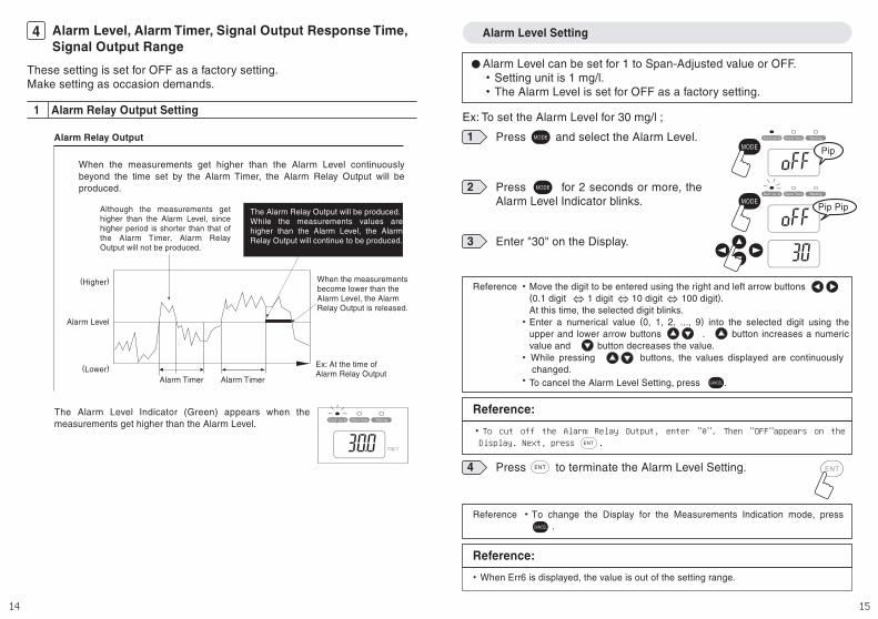
Alarm Timer can be set for 1 to 120 minutes or OFF.・Setting unit is 1 minute.・The Alarm Timer is set for OFF as a factory setting.
Alarm Timer Setting
Ex: To set the Alarm Timer for 60 minutes ;
4 Press to terminate the Alarm Timer Setting.
3 Enter "60" on the Display.
2
1
Press for 2 seconds or more, the Alarm Timer Indicator blinks.
Press and select the Alarm Timer.
Move the digit to be entered using the right and left arrow buttons (0.1 digit 1 digit 10 digit 100 digit). At this time, the selected digit blinks.
・
・
・
Reference ・
Enter a numerical value (0, 1, 2, ..., 9) into the selected digit using the upper and lower arrow buttons . button increases a numeric value and button decreases the value.While pressing buttons, the values displayed are continuously changed.
Reference:
・To cut off the Alarm Timer, enter "0". Then "OFF"appears on the Display. Next, press .
Reference ・To change the Display for the Measurements Indication mode, press .
To cancel the Alarm Timer Setting, press .
Reference:
・ When Err6 is displayed, the value is out of the setting range.
Pip
Pip Pip
Signal Output Response Time Setting2
Signal Output Response Time can be set for 1 to 120 seconds or OFF.・Setting unit is 1 second・The Signal Output Response Time is set for OFF as a factory setting.
Ex: To set the The Signal Output Response Time for 10 seconds ;
4 Press to terminate the Signal Output Response Time Setting.
3 Enter "10" on the Display.
2
1
Press for 2 seconds or more, the The Signal Output Response Time Indicator blinks.
Press and select the The Signal Output Response Time.
Move the digit to be entered using the right and left arrow buttons (0.1 digit 1 digit 10 digit 100 digit). At this time, the selected digit blinks.
・
・
・
Reference ・
Enter a numerical value (0, 1, 2, ..., 9) into the selected digit using the upper and lower arrow buttons . button increases a numeric value and button decreases the value.While pressing buttons, the values displayed are continuously changed.
Reference:
・To cut off the Signal Output Response Time, enter "0". Then "OFF"appears on the Display. Next, press .
Reference ・To change the Display for the Measurements Indication mode, press .
To cancel the Signal Output Response Time Setting, press .
Reference:
・ When Err6 is displayed, the value is out of the setting range.
Pip
Pip Pip

18 19
Signal Output Range Setting3
Signal Output Range can be set as follows.・"High Limit"-"Low Limit"≧200・Setting unit is 5 mg/l.・The Signal Output Range is default at 4mA for the 0-Adjustment
value and 20mA for the Span-Adjustment value.
Ex: To set the The Signal Output Range for 100 ~ 300 mg/l ;
4 Press to terminate the Signal Output Range Low Limit Setting.
3 Enter "100" on the Display.
2
1
Press for 2 seconds or more, the The Signal Output Low Limit value is displayed.
Press and select the The Signal Output Low Limit.
Move the digit to be entered using the right and left arrow buttons (0.1 digit 1 digit 10 digit 100 digit). At this time, the selected digit blinks.
・
・
・
Reference ・
Enter a numerical value (0, 1, 2, ..., 9) into the selected digit using the upper and lower arrow buttons . button increases a numeric value and button decreases the value.While pressing buttons, the values displayed are continuously changed.
Reference ・To change the Display for the Measurements Indication mode, press .
To cancel the Signal Output Low Limit Setting, press .
Reference:
・ When Err6 is displayed, the value is out of the setting range.
(1) Signal Output Low Limit Setting
Pip
※ "-Lo-" and "the setting value" comes on alternatively.
Pip Pip
4 Press to terminate the Signal Output Range High Limit Setting.
3 Enter "300" on the Display.
2
1
Press for 2 seconds or more, the The Signal Output High Limit value is displayed.
Press and select the The Signal Output High Limit.
Move the digit to be entered using the right and left arrow buttons (0.1 digit 1 digit 10 digit 100 digit). At this time, the selected digit blinks.
・
・
・
Reference ・
Enter a numerical value (0, 1, 2, ..., 9) into the selected digit using the upper and lower arrow buttons . button increases a numeric value and button decreases the value.While pressing buttons, the values displayed are continuously changed.
Reference ・To change the Display for the Measurements Indication mode, press .
To cancel the Signal Output High Limit Setting, press .
Reference:
・ When Err6 is displayed, the value is out of the setting range.
(2) Signal Output High Limit Setting
※ "-Hi-" and "the setting value" comes on alternatively.
Pip
Pip Pip
20 21
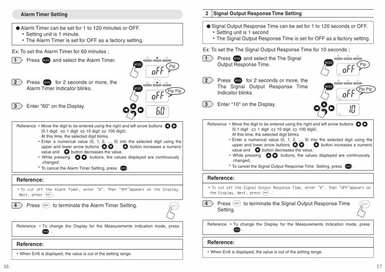
Fine Adjustment of Signal Output6Fine Adjustment of Lower Limit 4mA and Upper Limit 20mA of Signal Output (4-20mA) can be made.
・ When both right and left arrow buttons are pressed simultaneously, Signal Output of 4mA will be produced irrespectively of the measurement value.
CAUTION:
・ First make the Fine Adjustment of Lower Limit 4mA, and then make the Fine Adjustment of Upper Limit 20mA.・ Otherwise the value of the Upper Limit 20mA cannot be adjusted accurately.
CAUTION:
Fine Adjustment of Lower Limit 4mA1
2
1
While making sure of the values displayed by the connecting equipment such as recorder, make the Fine Adjustments of the Lower Limit 4mA with the up and down arrow buttons .
Simultaneously press both right and left arrow buttons .At this time, "-4-" is indicated in the Display. And, "ZERO" blinks and "SPAN" comes on.
+
4 Press to terminate the Fine Adjustments of the Lower Limit 4mA.
Reference ・To cancel the Fine Adjustment of the Lower Limit 4mA, press .
・ When both right and left arrow buttons are pressed simultaneously, Signal Output of 4mA will be produced irrespectively of the measurement value.
CAUTION:
Fine Adjustment of Upper Limit 20mA2
2
1
While making sure of the values displayed by the connecting equipment such as recorder, make the Fine Adjustments of the Upper Limit 20mA with the up and down arrow buttons .
Simultaneously press both right and left arrow buttons .At this time, "-20-" is indicated in the Display. And, "ZERO" comes on and "SPAN" blinks.
4 Press to terminate the Fine Adjustments of the Upper Limit 20mA.
Reference ・To cancel the Fine Adjustment of the Upper Limit 20mA, press .
+
22 23
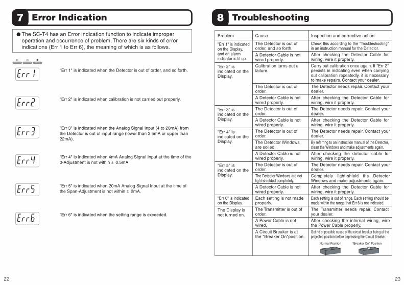
"Err 3" is indicated when the Analog Signal Input (4 to 20mA) from the Detector is out of input range (lower than 3.5mA or upper than 22mA).
"Err 5" is indicated when 20mA Analog Signal Input at the time of the Span-Adjustment is not within ±2mA.
"Err 4" is indicated when 4mA Analog Signal Input at the time of the 0-Adjustment is not within ±0.5mA.
"Err 6" is indicated when the setting range is exceeded.
"Err 2" is indicated when calibration is not carried out properly.
"Err 1" is indicated when the Detector is out of order, and so forth.
7The SC-T4 has an Error Indication function to indicate improper operation and occurrence of problem. There are six kinds of error indications (Err 1 to Err 6), the meaning of which is as follows.
Error Indication
"Err 1" is indicated on the Display, and an alarm indicator is lit up.
"Err 2" is indicated on the Display.
The Detector is out of order, and so forth.
A Detector Cable is not wired properly.
Check this according to the "Troubleshooting" in an instruction manual for the Detector.After checking the Detector Cable for wiring, wire it properly.
"Err 3" is indicated on the Display.
"Err 4" is indicated on the Display.
The Detector needs repair. Contact your dealer.
Carry out calibration once again. If "Err 2" persists in indicating even when carrying out calibration repeatedly, it is necessary to make repairs. Contact your dealer.
The Display is not turned on.
"Err 6" is indicated on the Display.
"Err 5" is indicated on the Display.
The Detector is out of order.
A Detector Cable is not wired properly.
The Detector is out of order.
A Detector Cable is not wired properly.
The Detector is out of order.
The Detector Windows are soiled.
A Detector Cable is not wired properly.
Each setting is not made properly.
The Transmitter is out of order.
A Power Cable is not wired.
A Circuit Breaker is at the "Breaker On"position.
A Detector Cable is not wired properly.
The Detector is out of order.
The Detector Windows are not light-shielded completely.
Calibration turns out a failure.
After checking the Detector Cable for wiring, wire it properly.
The Detector needs repair. Contact your dealer.
After checking the Detector Cable for wiring, wire it properly.
The Detector needs repair. Contact your dealer.
After checking the detector cable for wiring, wire it properly.
The Transmitter needs repair. Contact your dealer.
After checking the internal wiring, wire the Power Cable properly.
Get rid of possible cause of the circuit breaker being at the projected position before depressing the Circuit Breaker.
Each setting is out of range. Each setting should be made within the range that Err 6 is not indicated.
After checking the Detector Cable for wiring, wire it properly.
The Detector needs repair. Contact your dealer.
Completely light-shield the Detector Windows and make adjustments again.
By referring to an instruction manual of the Detector, clean the Windows and make adjustments again.
Problem Cause Inspection and corrective action
Normal Position "Breaker On" Position
8 Troubleshooting
24 25
Maintenance
Periodic inspection
Calibration
Long-term storage
When the Cover or the Display is soiled, first wipe away lightly with a clean soft cloth damped by diluted mild detergent solution and then wipe off moisture with a dry clean soft cloth.
Inspect the following items every 3 months: ・ Make sure that the Transmitter is fixed securely. ・ Make sure that the Transmitter is not damaged. ・ Make sure that the screws of the Terminal Block are not rusted.
The SC-T4 is designed so as to make measurements stably for a long time. In order to maintain the reliability of measurement, however, carry out calibration at least once a year (Refer to [5] Operation).
When the SC-T4 is not used for a prolonged period, turn off the Power Switch and disconnect the Power Cable from the power supply prior to safekeeping.
9 Maintenance
CAUTION:
・ Do not wipe the transmitter with solvent such as Thinner.
Calibration OutputPower Supply for Sensor (12 VDC)
Signal Output (analog 4-20mA, resistance load of 300Ω or less)Self-checking Relay Output (non-voltage C-contact capacity 240 VAC, 1A resistance load)
Alarm Relay Output (non-voltage C-contact capacity 240 VAC, 1A resistance load)Detector signal input (analog 4-20mA, input resistance approx.100Ω)
Self-checking input
IP65 (jetproof type)
AC100 ~ 240V±10% 50/60HzPower supply
Dimensions
SC-T4
0.5mg/L
Output
Power consumption
Normal: 8VA or less, during washing: 16VA or less (including detector, at the time of analog signal input/output of 20mA)
Display resolution
Input (detector)
The specifications herein are subject to change without prior notice due to improvements.
10 Specifications
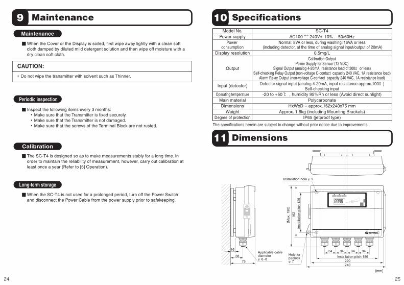
11 Dimensions
[mm]
16
38
75
34 34 34 34
220Installation pitch 186
Inst
alla
tion
pitc
h 12
5
240
(Max
. 190
)
162
Installation hole φ9
Applicable cable diameterφ6~8
Hole for padlockφ7
Model No.
Main materialOperating temperature -20 to +50 ℃ , humidity 95%Rh or less (Avoid direct sunlight)
Polycarbonate
Degree of protection
HxWxD = approx.162x240x75 mmWeight Approx. 1.6kg (including Mounting Brackets)