
Saxophone User™s Guide Rev 06/01 - · PDF fileSaxophone User™s Guide Rev 06/01...
43
Saxophone Users Guide Rev 06/01 Elmo Motion Control http://www.elmomc.com
Transcript of Saxophone User™s Guide Rev 06/01 - · PDF fileSaxophone User™s Guide Rev 06/01...

Saxophone
Users Guide Rev 06/01
Elmo Motion Control http://www.elmomc.com

Saxophone Users Guide Rev 06/01 Elmo Motion Controlhttp://www.elmomc.com
-1-
PROPRIETARY Notice hereby given that all data contained in, revealed by or shown in this document whether a drawing or other writing is proprietary and belongs to Elmo Motion Control LTD of Petach - Tikva , Israel. It is furnished and received in confidence solely for informational purposes of the recipient in connection with an actual or pending purchase or procurement of the product to which it relates. Neither the document nor any information, or data contained in it shall be used for any other purpose or duplicated or disclosed in whole or in part to anyone else without the prior written authorization of Elmo Motion Control LTD, any disclosure or revelation by the recipient to anyone else shall be accompanied by a written statement incorporating the language and contents of this legend.
Saxophone Users Guide Rev 06/01 Elmo Motion Controlhttp://www.elmomc.com
-2-
Table of Contents:
PROPRIETARY................................................................................................................................................ 1
1 INTRODUCTION ..................................................................................................................................... 7
2 SERVO AMPLIFIER DESCRIPTION ...................................................................................................... 8
2.1 General Structure and Connection ................................................................................................................. 9
2.2 Position Mode.................................................................................................................................................. 10
2.3 Protective Features ......................................................................................................................................... 10
2.4 Dedicated Features ......................................................................................................................................... 11
2.5 Saxophone Type Designation ......................................................................................................................... 12
2.6 Connections ..................................................................................................................................................... 13
2.7 Connector Types ............................................................................................................................................. 14
3 SOFTWARE INSTALLATION............................................................................................................... 15
4 WIRING AND MOUNTING .................................................................................................................... 16
4.1 General ............................................................................................................................................................ 16 4.1.1 Wiring .......................................................................................................................................................... 16 4.1.2 Mounting...................................................................................................................................................... 16
4.2 Connectors....................................................................................................................................................... 17 4.2.1 Main Power Connector ................................................................................................................................ 17 4.2.2 Auxiliary Power Connector.......................................................................................................................... 19 4.2.3 Committed I/O Connector............................................................................................................................ 19 4.2.4 General I/O Connector ................................................................................................................................. 20 4.2.5 Feedback A Connector - Encoder Option .................................................................................................... 21 4.2.6 Feedback A Connector - Resolver Option ................................................................................................... 22 4.2.7 Analog I/O Connector .................................................................................................................................. 23 4.2.8 Comm. 1 Connector ..................................................................................................................................... 24 4.2.9 Comm. 2 Connector (Valid for SAX-P, SAX-PP Types) ............................................................................ 25 4.2.10 Feedback B Connector ............................................................................................................................ 25
5 POWER UP............................................................................................................................................ 26
5.1 Before Applying Power .................................................................................................................................. 26
5.2 Voltage supply................................................................................................................................................. 26
5.3 Saxophone Setup and Initialization............................................................................................................... 26
6 TROUBLE SHOOTING GUIDE............................................................................................................. 27
7 TECHNICAL SPECIFICATIONS........................................................................................................... 28
7.1 Introduction..................................................................................................................................................... 28 7.1.1 Control specifications .................................................................................................................................. 28

Saxophone Users Guide Rev 06/01 Elmo Motion Controlhttp://www.elmomc.com
-3-
7.1.2 Feedback options ......................................................................................................................................... 30
7.2 Input Specification.......................................................................................................................................... 30
7.3 Output Specification ....................................................................................................................................... 31 7.3.1 Fault Output ................................................................................................................................................. 32
7.4 Display ............................................................................................................................................................. 33 7.4.1 Power Ratings .............................................................................................................................................. 33 7.4.2 Single Phase Operation ................................................................................................................................ 35 7.4.3 Mechanical Specifications ........................................................................................................................... 35 7.4.4 Recommended Wire Cross-sections............................................................................................................. 35 7.4.5 Environmental Conditions Specifications .................................................................................................... 36
7.5 Resolver ........................................................................................................................................................... 36
7.6 Relevant Standards......................................................................................................................................... 37 7.6.1 Quality Assurance ........................................................................................................................................ 37 7.6.2 Design .......................................................................................................................................................... 37 7.6.3 Safety ........................................................................................................................................................... 37 7.6.4 EMC............................................................................................................................................................. 37 7.6.5 Workmanship ............................................................................................................................................... 37 7.6.6 PCB.............................................................................................................................................................. 37 7.6.7 Packing......................................................................................................................................................... 37
APPENDIX 1: DIMENSIONAL DRAWINGS ........................................................................................... 38
APPENDIX 2: SAXOPHONE PLUS, PLUS PLUS (SAX-P, SAX-PP) ................................................... 40
Service Centers and Warranty..................................................................................................................................... 42
Service Centers and Warranty..................................................................................................................................... 42
Warranty performance................................................................................................................................................. 42
Saxophone Users Guide Rev 06/01 Elmo Motion Controlhttp://www.elmomc.com
-4-
List of Figures:
Figure 1: Dedicated I/O.................................................................................................................................... 9 Figure 2: Type Designation ............................................................................................................................ 12 Figure 3: Panel Layout ................................................................................................................................... 13 Figure 4: Power Terminal Connections.......................................................................................................... 17 Figure 5: Motor Power Connection................................................................................................................ 18 Figure 6: Encoder / Hall sensor Pin Assignment............................................................................................ 21 Figure 7: Resolver Connection....................................................................................................................... 22 Figure 8: Analog input with single-ended source........................................................................................... 23 Figure 9: RS232 Interface .............................................................................................................................. 24 Figure 10: RS485 Interface ............................................................................................................................ 24 Figure 11: Digital Input Schematic ................................................................................................................ 30 Figure 12: Digital Output Schematic.............................................................................................................. 31 Figure 13: Relay connection........................................................................................................................... 32 Figure 14: Single phase voltage drop ............................................................................................................. 35 Figure 15: Operating ambient temperature at nominal operating voltage...................................................... 36 Figure 16: SAX General Dimensions drawing............................................................................................ 38 Figure 17: SAX - Mounting Dimensions Drawing ........................................................................................ 39 Figure 18: SAX-Pxx/yyy CAN interface........................................................................................................ 40 Figure 19: Auxiliary encoder in master - slave configuration........................................................................ 41 Figure 20: Auxiliary encoder, independent encoder configuration. ............................................................... 41
Saxophone Users Guide Rev 06/01 Elmo Motion Controlhttp://www.elmomc.com
-5-
List of Tables:
Table 1: Dedicated features ............................................................................................................................ 11 Table 2: Amplifier Types ............................................................................................................................... 12 Table 3: Connector Types .............................................................................................................................. 14 Table 4: Main Power Connection Pinout ....................................................................................................... 17 Table 5: Auxiliary Power Connection Pinout................................................................................................. 19 Table 6: 9 Pin D type Male Connector Pinout.............................................................................................. 19 Table 7: 25 Pin D Type Female Connector Pinout....................................................................................... 20 Table 8: 15 Pin D Type Female Connector Pinout....................................................................................... 21 Table 9: 15 Pin D Type Female Connector Pinout....................................................................................... 22 Table 10: 9 Pin D Type Female Connector Pinout....................................................................................... 23 Table 11: Comm. 1 - 9 Pin D Type Female Connector Pinout..................................................................... 24 Table 12: Comm. 2 - 9 Pin D Type Male Connector Pinout ........................................................................ 25 Table 13: 15 Pin D Type Male Connector Pinout ........................................................................................ 25 Table 14: Trouble Shooting Guide ................................................................................................................. 27 Table 15: Control Specifications .................................................................................................................... 29 Table 16: Feedback Options........................................................................................................................... 30 Table 17: Digital Inputs Interface................................................................................................................... 30 Table 18: Digital Output Interface.................................................................................................................. 31 Table 19: Display ........................................................................................................................................... 33 Table 20: 1 or 3x230VAC Types Power Ratings ........................................................................................... 33 Table 21: 3x400VAC Types Power Ratings .................................................................................................. 33 Table 22: Power Ratings ................................................................................................................................ 34 Table 23: Auxiliary Power Supply ................................................................................................................. 34 Table 24: Analog I/O Rating .......................................................................................................................... 34 Table 25: Supply Voltage............................................................................................................................... 34 Table 26: Mechanical Specifications.............................................................................................................. 35 Table 27: Recommended wire cross-sections ................................................................................................ 35 Table 28: Environmental Conditions Specifications ...................................................................................... 36

Saxophone Users Guide Rev 06/01 Elmo Motion Controlhttp://www.elmomc.com
-6-
SAFETY INFORMATION Saxophone - Safety Information
Please read this page carefully before installation and use of the instrument, and follow all instructions in section 4 of Users Guide for safe installation of this product. INTRODUCTION: The following clauses contain information, cautions and warnings that must be followed to ensure safe operation and to retain the instrument in a safe condition. This product is intended for incorporation into a machine or end product. The end product must comply with all safety aspects of the relevant requirements of the European Safety of Machinery Directive 89/392/EEC as amended, and with those of the most recent versions of standards EN60204-1 and EN292-2 at least. Only qualified personnel shall carry out installation, adjustment, maintenance and repair of the instrument. The Saxophone conforms to the following industry safety standards: Power Conversion equipment Recognized UL508c
Insulation Coordination Including Clearance and Creepage Distances Of Electrical Equipment
In compliance with UL840.
Safety of Information Technology Equipment, Including Electrical Business Equipment
In compliance with UL1950.
Low Voltage Directive, 73/23/EEC. In compliance with EN60204-1.
WARNINGS: Any removal from the structure or removal of parts, except those to which access is permitted, is likely to expose live parts and accessible terminals, which can be dangerous to life. Any adjustment, maintenance or repair, of the opened instrument under voltage, shall be performed only by a qualified person who is aware of the hazard involved. The instrument shall be disconnected from all voltage sources before it is opened (for service method). Any interruption of the protective earth conductors inside the instrument is likely to make the instrument dangerous. Components, which are important for the safety of the instrument, may only be renewed by components obtained through Elmo service organization. Before switching on, ensure that the instrument has been installed in accordance with the Installation Instructions. Maximum AC & DC supplies must be according to the types described in the operating manual.

Saxophone Users Guide Rev 06/01 Elmo Motion Controlhttp://www.elmomc.com
-7-
1 Introduction The Saxophone User Guide is written for the design engineer or technician who will connect and operate the Saxophone servo amplifier. The Users Guide contains the following information: Chapter 1 Provides a general description of the Saxophone Users Guide.
Chapter 2 Describes the Saxophone servo amplifier and its features.
Chapter 3 Instructions for installing Composer, the Saxophones Windows based set-up and diagnostic software..
Chapter 4 Provides details for the Saxophone wiring and mounting.
Chapter 5 Provides power up information as well as a short getting started guide that describes the Saxophone setup wizard
Chapter 6 Provides details for tuning the Saxophone
Chapter 7 Provides a troubleshooting guide to the Saxophone
Chapter 8 Provides technical specifications for the Saxophone.
Appendix 1 Provides dimensional drawings for the Saxophone.

Saxophone Users Guide Rev 06/01 Elmo Motion Controlhttp://www.elmomc.com
-8-
2 Servo Amplifier Description The Saxophone series of servo amplifiers for Permanent Magnet Synchronous Motors (PMSM) incorporates digital velocity loop, digital current loop and sinusoidal commutation. Permanent Magnet Synchronous Motors, or Brushless AC (DC) motors (BLM) are used in high performance drives for machine tools and robotics. Independent control of the magnetic flux and the torque-generating current component in motors is provided by sinusoidal control with phase advance algorithms. The advantages of sinusoidal control are:
High motor efficiency due to flux vector control. Smooth torque operation (low torque ripple) even at very low speed enables high
positioning accuracy. Good velocity control under varying load conditions
The Saxophone series basic configuration comprises a velocity amplifier with digital velocity loop targeting the OEM market. All adjustments of the velocity, current, and PID-filter are done via the communication line (using a PC), eliminating the need for trimmers. The Saxophones power source is either a 3 phase 400 VAC line (SAX-xx/400) or a 1 or 3 phase 230 VAC line (SAX-xx/230). The control and auxiliary supplies are derived from a 24V AC/DC supply, which is isolated from the DC power bus. This feature provides a safe and economical power back-up which is essential for position systems. The Saxophone series meets UL508c and the relevant CE regulations.

Saxophone Users Guide Rev 06/01 Elmo Motion Controlhttp://www.elmomc.com
-9-
2.1 General Structure and Connection
CANopen
(option)Interface
Analog command
Aux. EncoderInterface
Aux.Encoder
RS232
Main EncoderInterface
ResolverInterface(option)
Dadicated I/O:Enable/DisableLimit SwitchesAbort Fault
MCU+
I/O
Motor
Feedback
RS485Interface(Option) AC1
AC2
AC3
M1
M3
M2
Main Power3x400 AC
Aux. Power:24VDC
or24VAC
Bridge Commands(6 x PWM)
Status Lines
Current FeedbackPhase - M1Phase - M3
InternalPowerSupply
PowerStage
Encoder output
+5v, 15v, 24v
PE
General I/O
Circuitbreaker
Contactor
PE
Figure 1: Dedicated I/O
For three phases supply voltage: • The circuit breaker current rating should be between 150% to 200%, of the amplifiers
current. • The circuit breaker voltage rating should be 460 VAC. • The contactor should be up to 150% of the amplifiers current. For one phase supply voltage: • The circuit breaker current rating should be between 200% to 300%, of the amplifiers
current. • The circuit breaker voltage rating should be 460 VAC. • The contactor should be up to 200% of the amplifiers current.

Saxophone Users Guide Rev 06/01 Elmo Motion Controlhttp://www.elmomc.com
-10-
2.2 Position Mode
Operation directly from the Mains, 3φ 230VAC to 460VAC (SAX xx/400) or a 1φ or 3φ 115VAC to 230VAC (SAX xx/230).
Operation in current mode, velocity mode or position mode. All adjustments via the communication line (using a PC). Differential analog input with 12-bit resolution. DC to DC converter allows operation from 24V AC/DC supply (Backup). Zero dead-band. Excellent linearity. Status indication (7 segment LED). Latch mode of the protective functions. Automatic velocity loop offset adjustment. Automatic current loop offset adjustment. Automatic alignment includes:
− Alignment when only digital Hall sensors are available, and where no initial knowledge of the Halls order and polarity is assumed.
− Alignment with encoder and Hall sensors. − Alignment with encoder and no Hall sensors. − Alignment with resolver - no Hall sensors.
Resolver - option. Encoder STD.
2.3 Protective Features
The Saxophone is protected against: Short between the motor power outputs. Short between each motor power output and power input return. Failure of the internal power supplies. Over temperature. Under / over voltage. Loss of commutation signals. Loss of velocity feedback. High velocity error. High or low (minus) velocity feedback. Bad commutation. Communication error.

Saxophone Users Guide Rev 06/01 Elmo Motion Controlhttp://www.elmomc.com
-11-
2.4 Dedicated Features
Feature Standard Plus PlusPlus
CANopen interface No Yes Yes
Current mode Yes Yes Yes
Velocity mode Yes Yes Yes
Velocity follower Yes Yes Yes
Two encoder inputs Yes Yes Yes
Two analog inputs Yes Yes Yes
Executable commands Yes Yes Yes
Point to point No Yes Yes
Position Follower No Yes Yes
Position jog No Yes Yes
ECAM No No Yes
PT No Yes Yes
PVT No Yes Yes
Event capturing No No 2
Dual loop No No Yes
User program size 2 Kbyte 2 Kbyte 32 Kbyte
General inputs 2 2 6
General outputs 2 2 6
Table 1: Dedicated features

Saxophone Users Guide Rev 06/01 Elmo Motion Controlhttp://www.elmomc.com
-12-
2.5 Saxophone Type Designation
SAXOPHONE
Rated Phase ContinuousRMS Current
Blank = Velocity P = PlusPP = Plus Plus
Option:R = Resolver
Nominal OperatingAC Voltage
Figure 2: Type Designation
Amplifier Types
SAX-3/230
SAX-5/230
SAX-8/230
SAX-14/230 (3 Phases only)
SAX-3/400
SAX-4/400
SAX-8/400
SAX-10/400
SAX-14/400
Table 2: Amplifier Types

Saxophone Users Guide Rev 06/01 Elmo Motion Controlhttp://www.elmomc.com
-13-
2.6 Connections
Figure 3 shows the front panel of the Saxophone.
FEEDBACK B
J2- AUX. POWER
24v 24v
AC3AC2AC1PEM3M2M1
J1- POWER
FEEDBACK A
ANALOG I/O
COMMITTED I/O
COMM. 1
COMM. 2
GENERAL I/O
Elmo
MOTOR POWER
5 1
69
1
13 1
5
96
25 14
18
915
81
159
5 1
69
1 5
96
Figure 3: Panel Layout
Saxophone Users Guide Rev 06/01 Elmo Motion Controlhttp://www.elmomc.com
-14-
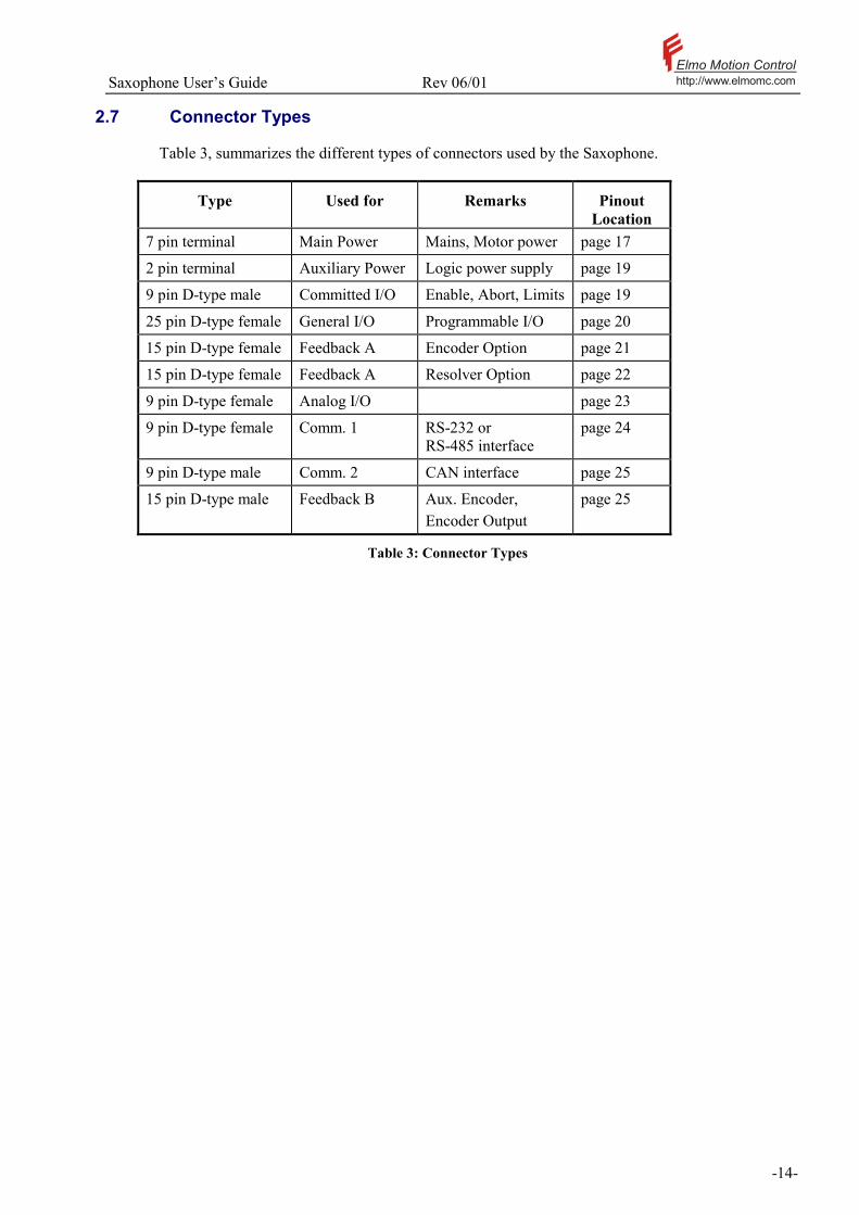
2.7 Connector Types
Table 3, summarizes the different types of connectors used by the Saxophone.
Type Used for Remarks Pinout Location
7 pin terminal Main Power Mains, Motor power page 17
2 pin terminal Auxiliary Power Logic power supply page 19
9 pin D-type male Committed I/O Enable, Abort, Limits page 19
25 pin D-type female General I/O Programmable I/O page 20
15 pin D-type female Feedback A Encoder Option page 21
15 pin D-type female Feedback A Resolver Option page 22
9 pin D-type female Analog I/O page 23
9 pin D-type female Comm. 1 RS-232 or RS-485 interface
page 24
9 pin D-type male Comm. 2 CAN interface page 25
15 pin D-type male Feedback B Aux. Encoder, Encoder Output
page 25
Table 3: Connector Types

Saxophone Users Guide Rev 06/01 Elmo Motion Controlhttp://www.elmomc.com
-15-
3 Software Installation The composer is a Windows based software, designed for setup and analyzes of motion control systems using Elmo amplifiers. For more details about the composer please refer the composer software manual.

Saxophone Users Guide Rev 06/01 Elmo Motion Controlhttp://www.elmomc.com
-16-
4 Wiring and Mounting 4.1 General
4.1.1 Wiring
Proper wiring, grounding and shielding techniques are important in obtaining good servo operation and performance. Incorrect wiring, grounding or shielding can cause erratic servo performance or even complete failure.
1. Keep motor wires as far as possible from the signal level wiring (feedback signals, control signals, etc.).
2. If additional inductors (chokes) are required, keep the wires between the amplifier and the chokes as short as possible.
3. Minimize lead lengths as much as it is practical. Although the amplifier is protected against long (inductive) supply wires, it is recommended to keep the leads as short as possible. For cable length of over 10m (35 feet) consult factory for more technical instructions.
4. It is recommended to use twisted and shielded wires whenever it is possible to do so in the wiring diagrams. Avoid running these leads in close proximity to power leads or other sources of EMI noise.
5. All grounded components should be tied together at a single point (star connection). This point should then be tied with a single conductor to an earth ground point.
6. After wiring is completed, carefully inspect all conditions to ensure tightness, good solder joints, etc.
4.1.2 Mounting
For optimum heat dissipation the amplifier has to be mounted in vertical position. A clearance of at least 10cm (4) should be left at both top and bottom of the unit.

Saxophone Users Guide Rev 06/01 Elmo Motion Controlhttp://www.elmomc.com
-17-
4.2 Connectors
The following sections provide the pin outs for the Saxophone connectors. Schematics for certain cables are also provided.
4.2.1 Main Power Connector
Signal Function AC3 Main voltage phase 3
AC2 Main voltage phase 2
AC1 Main voltage phase 1
PE Protective Earth
M3 Motor phase W
M2 Motor phase V
M1 Motor phase U
Table 4: Main Power Connection Pinout
Figure 4: Power Terminal Connections

Saxophone Users Guide Rev 06/01 Elmo Motion Controlhttp://www.elmomc.com
-18-
Motor
M1
M2
M3
A
B
C
Chassis
PE
SAXOPHONE
Figure 5: Motor Power Connection

Saxophone Users Guide Rev 06/01 Elmo Motion Controlhttp://www.elmomc.com
-19-
4.2.2 Auxiliary Power Connector
Pin # Signal Function 1 APS1 (24 V) Auxiliary supply 24VDC/VAC
2 APS2 (24 V) Auxiliary supply 24VDC/VAC
Table 5: Auxiliary Power Connection Pinout
4.2.3 Committed I/O Connector
Pin # Signal Function 1 FLS Forward limit switch
2 RLS Reverse limit switch
3 LSRET Limit switch return
4 ENABLE Amplifier Enable (Disabling resets any protective latch)
5 ENRET Amplifier Enable Return
6 STOP Applying power to this terminal will stop the motor at maximum deceleration
7 STRET Stop Return
8 FAULT Fault Relay (see Figure 13)
9 FAULT Fault Relay (see Figure 13)
Table 6: 9 Pin D type Male Connector Pinout

Saxophone Users Guide Rev 06/01 Elmo Motion Controlhttp://www.elmomc.com
-20-
4.2.4 General I/O Connector
Pin # Signal Function Remarks
1 IN1 Programmable input 1
2 IN2 Programmable input 2
3 IN3 Programmable input 3
4 IN4 Programmable input 4
5 IN5 Programmable input 5 • Event Capture input. • MAIN HOME input.
6 IN6 Programmable input 6 • Event Capture input • Aux. HOME input.
SAX-PP only
7 NA
8 OUT1 Programmable output 1
9 OUT2 Programmable output 2
10 OUT3 Programmable output 3
11 OUT4 Programmable output 4
12 OUT5 Programmable output 5
13 OUT6 Programmable output 6
SAX-PP only
14 INRET1 Programmable input return 1
15 INRET2 Programmable input return 2
16 INRET3 Programmable input return 3
17 INRET4 Programmable input return 4
18 HOMERET HOME return 1
19 AHOMERET AHOME return 2
SAX-PP only
20 OUTRET1 Programmable output return 1
21 OUTRET2 Programmable output return 2
22 OUTRET3 Programmable output return 3
23 OUTRET4 Programmable output return 4
24 OUTRET5 Programmable output return 5
25 OUTRET6 Programmable output return 6
SAX-PP only
Table 7: 25 Pin D Type Female Connector Pinout

Saxophone Users Guide Rev 06/01 Elmo Motion Controlhttp://www.elmomc.com
-21-
4.2.5 Feedback A Connector - Encoder Option
Pin # Signal Function 1 HC Hall sensor C input
2 HA Hall sensor A input
3 SUPRET Hall/Encoder supply voltage return
4 +5V ENCODER/HALL +5V supply voltage (See Table 25)
5 CHA- Channel A complement
6 CHA Channel A
7 INDEX- Index complement
8 INDEX Index
9 SUPRET Supply return
10 HB Hall sensor B input
11 SUPRET Supply return
12 +15V HALL +15V supply voltage (See Table 25)
13 SUPRET Supply return
14 CHB- Channel B complement
15 CHB Channel B
Table 8: 15 Pin D Type Female Connector Pinout
15 Pin FemaleConnector
Hall C
Hall A
Hall / Encoder Supply Voltage Return
Encoder / Hall +5v Supply
CHA-
CHA
Index -
Index
Hall Sensor B Input
Hall +15v Supply ( if required)
CHB -
CHB
Encoder/ Hall Sensor
SAX - FEEDBACK A MOTOR
1
2
3
4
5
6
7
89
10
11
12
13
14
15
HC
HA
SUPRET
+5v
CHA-
CHA
INDEX-
INDEX
SUPRET
HBSUPRET
+15v
SUPRET
CHB-
CHB
Figure 6: Encoder / Hall sensor Pin Assignment

Saxophone Users Guide Rev 06/01 Elmo Motion Controlhttp://www.elmomc.com
-22-
4.2.6 Feedback A Connector - Resolver Option
Pin # Signal Function 6 R1 Resolver Reference output R1
7 S2 Resolver Cosine input S2
8 S1 Resolver Sine input S1
9 S3 Resolver Sine input S3
11 SCREEN Cable shield should be connected to this terminal
3,13 SUPRET Supply Return
14 R2 Resolver Reference output R2
15 S4 Resolver Cosine input S4
Table 9: 15 Pin D Type Female Connector Pinout
Sine S1
Sine S3
Reference R1
Reference R2
Cosine S2
Cosine S4
6
7
8
9
3
11
13
14
15
R1
S2S1
S3
SCREEN
SUPRET
R2
S4
D Type 15 Pin FemaleConnector
Resolver
SAX - FEEDBACK A(RESOLVER OPTION)
Motor
SUPRET
Figure 7: Resolver Connection

Saxophone Users Guide Rev 06/01 Elmo Motion Controlhttp://www.elmomc.com
-23-
4.2.7 Analog I/O Connector
Pin # Signal Function 1 ANLIN1+ Analog input 1
2 ANLIN1- Analog input 1
3 ANLRET Analog Ground
4 ANLIN2+ Analog input 2
5 ANLIN2- Analog input 2
6 GND Circuit common
7 ANLOUT Analog output
8 ANLRET Analog Ground
9 GND Circuit common
Table 10: 9 Pin D Type Female Connector Pinout
+
-
20K4.
99K
20K
ANLIN1+ 1
3ANLRET
2
RETURN
+
-
Single-EndedSource SAX
ANLIN1-
+
-
20K
4.99
K
20K
4
5ANLIN2-
ANLIN2+
Figure 8: Analog input with single-ended source
Note: We recommended to connect the ANLRET line to GND, even when the analog
Interface not used.

Saxophone Users Guide Rev 06/01 Elmo Motion Controlhttp://www.elmomc.com
-24-
4.2.8 Comm. 1 Connector
Pin # Signal Function 1 N.C.
2 Tx RS232 Transmit
3 Rx RS232 Receive
4 N.C.
5 COMRET Communication Return
6 TR+ RS485 TR+ (an option)
7 TR- RS485 TR- (an option)
8 N.C.
9 N.C.
Table 11: Comm. 1 - 9 Pin D Type Female Connector Pinout
D-Type9 pin
Female
Figure 9: RS232 Interface
D-Type
Figure 10: RS485 Interface
Note: When the RS485 option is in the amplifier, a standard modem cable, for the RS232 connection, might damage the RS485 transceiver because of the control signals of the RS232, which are conflicting with the RS485 input. In this cases a 3 wires cable required according Figure 9.
Saxophone Users Guide Rev 06/01 Elmo Motion Controlhttp://www.elmomc.com
-25-
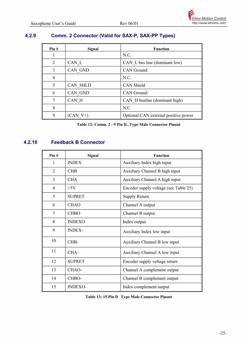
4.2.9 Comm. 2 Connector (Valid for SAX-P, SAX-PP Types)
Pin # Signal Function 1 N.C.
2 CAN_L CAN_L bus line (dominant low)
3 CAN_GND CAN Ground
4 N.C.
5 CAN_SHLD CAN Shield
6 CAN_GND CAN Ground
7 CAN_H CAN_H busline (dominant high)
8 N.C.
9 (CAN_V+) Optional CAN external positive power
Table 12: Comm. 2 - 9 Pin D Type Male Connector Pinout
4.2.10 Feedback B Connector
Pin # Signal Function
1 INDEX Auxiliary Index high input
2 CHB Auxiliary Channel B high input
3 CHA Auxiliary Channel A high input
4 +5V Encoder supply voltage (see Table 25)
5 SUPRET Supply Return
6 CHAO Channel A output
7 CHBO Channel B output
8 INDEXO Index output
9 INDEX- Auxiliary Index low input
10 CHB- Auxiliary Channel B low input
11 CHA- Auxiliary Channel A low input
12 SUPRET Encoder supply voltage return
13 CHAO- Channel A complement output
14 CHBO- Channel B complement output
15 INDEXO- Index complement output
Table 13: 15 Pin D Type Male Connector Pinout

Saxophone Users Guide Rev 06/01 Elmo Motion Controlhttp://www.elmomc.com
-26-
5 Power Up 5.1 Before Applying Power
1. Make sure that the AC supply is within the unit's specifications.
5.2 Voltage supply
5.3 Saxophone Setup and Initialization
After completing all the connections, it is necessary to setup and initialize the system. Description of the initial setup and initialization for the Saxophone using Elmos Composer Software, refer to the Composer Software Manual.
The Saxophone SAX-xx/400 series is designed to operate only from a 3-phase voltage source The Saxophone SAX-xx/230 series is designed to operate from a 1 or 3-phase voltage source. It can be connected directly to the line voltage. It is not necessary to use an isolation transformer.

Saxophone Users Guide Rev 06/01 Elmo Motion Controlhttp://www.elmomc.com
-27-
6 Trouble Shooting Guide
7-segment display Status Action
Disable Bridge is disable (all the switches are off), no
fault.
Enable All OK (amplifier is ready).
Under voltage Bus voltage is too low.
Over voltage Bus voltage is too high.
SVP Internal power supply problem.
Shunt The Shunt is operating.
Short Phases are shorted to each other or to the ground.
Ishort = 3 × Ipeak
Temperature Amplifier temperature is too high.
Feedback Feedback loss.
FLS Forward switch is active according to the defined
logic (IL[3]).
RLS Reverse switch is active according to the defined
logic (IL[4]).
FLS&RLS Both switch are active together.
Over speed Speed exceeded high or low limitation (HL[2],
LL[2]).
IC Continuous current limit is active.
IP Peak current limit is active.
Over current Current exceeded peak current limitation.
Undeclared fault Fault, which is not under the declaration of the
LED. May be detected with MF command.
Table 14: Trouble Shooting Guide

Saxophone Users Guide Rev 06/01 Elmo Motion Controlhttp://www.elmomc.com
-28-
7 Technical Specifications 7.1 Introduction
This chapter provides technical details for the: Control Specifications Feedback Options Saxophone Power Ratings Rated Specifications Auxiliary Power Supply Mechanical Specifications Environmental Conditions Specifications Reference Command Input (REF+, REF-) Resolver RS-485 interface (OPTION) Relevant Standards Radiation Safety
7.1.1 Control specifications
Feature Description Sampling time of the velocity loop x4 current loop sample time
Current control Digital Sinusoidal with vector control Programmable PI control filter
Based on a pair of PI controls of AC current signals and constant power at high speed.
Current loop BW Approx. 1.2 kHz
Current loop step response (including the settling time).
300 400 µs
Current rise time 150 200 µs
Current rise delay time The time it takes from applying the command until the current starts to rise. This delay is due to the digital processing (100 - 200 µs)
Resolution of current loop 12 bits
A/D resolution of the reference input command
12 bits
Commutation feedback options Digital Hall Effects +Incremental encoder. Resolver. Incremental encoder only Pulse/direction
Current Command Analog input 12 bits resolution (the same input used for the velocity command).
Velocity control Digital Programmable PID + FFW control filter. Sampling rate x4 current loop sample time.

Saxophone Users Guide Rev 06/01 Elmo Motion Controlhttp://www.elmomc.com
-29-
Feature Description Velocity and position feedback options Resolver
Incremental encoder Digital Hall Effect (velocity only) Note: With all feedback options the 1/T
with automatic modes switching will be activated (gap, frequency and derivative).
Velocity command options: Analog Internally calculated by one of:
− Jogging − Step
Note: All software calculated profiles support on-the-fly changes
Resolution of the analog output See Table 24
PWM Switching frequency Factory default 18Khz on the motor
Switching method Advanced Unipolar PWM
Control inputs PLC level only
Table 15: Control Specifications

Saxophone Users Guide Rev 06/01 Elmo Motion Controlhttp://www.elmomc.com
-30-
7.1.2 Feedback options
Feature Description Type of encoder Differential.
Quadrature. Interface: RS422
Input terminating resistor 300 ohm
Max incremental encoder frequency: Max absolute: 2 MHz single (8 MHz quadrature).
Input voltages range for the encoder Max common mode ±7V. Max differential mode ±7V.
Table 16: Feedback Options
7.2 Input Specification
Figure 8 shows the Digital Input Schematic for the Saxophone series of servo amplifiers.
GroupCommon
In(i)
Rin=2.49KVz=5.1v
V =1.5vF
Figure 11: Digital Input Schematic
Feature Description
Type of input Optically isolated. Single ended.
Input current RinVfVzViIin −−=
* Iin = 2.2mA @ Vin = 12V Min input current @ Vi=24V Iin = 7mA High level input voltage 12V < Vin < 30V Low level input voltage 0V < Vin < 7V Min pulse width (IN1 IN4) 1msec. Execution time (all inputs) 500µs < T ≤ 2ms High speed input capture min pulse width capture on input transition (IN5 IN6) 20µs < T ≤ 50µs
Table 17: Digital Inputs Interface

Saxophone Users Guide Rev 06/01 Elmo Motion Controlhttp://www.elmomc.com
-31-
7.3 Output Specification
Figure 9 shows the Digital Output Schematics for the Saxophone series of servo amplifiers
Rout=25.5Ω
33v
RL
Vcc
Output(i)
Vout
Output(i)
SAX
Figure 12: Digital Output Schematic
Feature Description Type of output Optically isolated. Max Supply output (Vcc) 30V Max output current Io(max) (Vout = Low) TTL level: IOL < 2mA, VOL < 0.8
PLC level: IOL ≅ 10mA, VOL < 3v VOL @ maximum output voltage ( low level )
TTL level: Vcc = 5v, Vout = 0.8v PLC level: Vcc = 24v, Vout = 3v
Min RL
(max)O
OLCCL
IVVR −≥
Executable time Up to 2msec
Table 18: Digital Output Interface

Saxophone Users Guide Rev 06/01 Elmo Motion Controlhttp://www.elmomc.com
-32-
7.3.1 Fault Output
The fault output switches in case of one of the hardware failures occur.
FAULT
8
9
RELAYN.O.
Figure 13: Relay connection
Amp Status Relay Contact Status
No Fault Close Fault Open
Switching Current 0.25A max. Switching Voltage 40v AC/DC

Saxophone Users Guide Rev 06/01 Elmo Motion Controlhttp://www.elmomc.com
-33-
7.4 Display
Feature Description 1-digit 7-segment LED display Displays amplifiers operating condition
See Trouble Shooting Guide for details
Table 19: Display
7.4.1 Power Ratings
This section provides technical information regarding the Saxophones power ratings.
Type Phase RMS Continuous
Current Amperes*
Phase RMS Peak
Current Amperes*
Nominal Operating
Voltage VAC
DC Bus Over
Voltage Protection
Volts
DC Bus Under
Voltage Protection
Volts
Shunt Current Amperes
SAX-3/230 3 5 1x230 or
3x230
390 78 4.0
SAX-5/230 5 10 1x230 or
3x230
390 78 4.0
SAX-8/230 8.5 17 1x230 or
3x230
390 78 8.0
Table 20: 1 or 3x230VAC Types Power Ratings
Type Phase RMS Continuous
Current Amperes*
Phase RMS Peak
Current Amperes*
Nominal Operating
Voltage VAC
DC Bus Over
Voltage Protection
Volts
DC Bus Under
Voltage Protection
Volts
Shunt Current Amperes
SAX-3/400 3.0 6.0 3X400 765 153 7.0
SAX-4/400 4.5 9.0 3X400 765 153 7.0
SAX-8/400 8.5 17.0 3X400 765 153 7.0
SAX-10/400 10.5 21.0 3X400 765 153 14.0
SAX-14/400 14.0 28.0 3X400 765 153 14.0
Table 21: 3x400VAC Types Power Ratings
Note: The power rating is defined for 10Khz switching frequency on the motors winding.

Saxophone Users Guide Rev 06/01 Elmo Motion Controlhttp://www.elmomc.com
-34-
Rated Specifications Unit SAX-xx/230 SAX-xx/400 Rated supply voltage VAC 3 x 240 + max10% 3 x 460 max
Pulse power of ballast circuit kW 1.5/3 5/10
Continuous power of ballast circuit W 80/160 80/160
Switch-off threshold at over voltage VDC 390 765
Inrush current limit A <85 <140
Efficiency @ Rated POWER % >95 >97
Table 22: Power Ratings
Auxiliary Power Supply Source The source of the auxiliary power supply can be AC or DC source.
AC input AC voltage input: 18 VAC< VIN(AC) < 28 VAC
DC Input DC voltage input: 18 VDC < VIN(DC) < 40 VDC
Power rating of the source 40 VA
Input frequency Input Frequency: 45 Hz < f IN < 500 Hz.
Table 23: Auxiliary Power Supply
Analog Input - differential mode voltage + / - 20V max.
Analog Input - common mode voltage + / - 10V max.
Input Resistance 5K
Analog Output voltage + / - 10V max. (10KΩ impedance)
Analog Output accuracy + / - 3%
Table 24: Analog I/O Rating
Encoders Supply Voltage 5V + / - 5%
Hall Effect Supply Voltage 5V or 15V + / - 5%
Encoder Supply Current (pin 4 of feedback A and B)
300mA max. (Total for both outputs)
Hall Effect Supply Current 50mA max.
Table 25: Supply Voltage
For encoder input/output see Table 16

Saxophone Users Guide Rev 06/01 Elmo Motion Controlhttp://www.elmomc.com
-35-
7.4.2 Single Phase Operation
When operating with a single-phase supply (SAX-xx/230 only), the voltage drop must be considered. Voltage drop can be calculated with the following equation: Vout (Max Phase to phase)= 0.85*[ Vsupply (AC) Vdrop]
Vdrop ACRMS
0.00
5.00
10.00
15.00
20.00
25.00
30.00
35.00
1 2 3 4 5 6 7 8 9 10 11
Motor's phase current RMS
Vdrop ACRMS
Figure 14: Single phase voltage drop
7.4.3 Mechanical Specifications
Mounting method Bookshelf
Overall dimensions 247 x 188 x 92 mm (9.72 x 7.4 x 3.6 in)
Weight SAX-14/400 2.7 KG (6 LBS)
Table 26: Mechanical Specifications
7.4.4 Recommended Wire Cross-sections
Model AC Input Motor Auxiliary SAX-3/230 1.5 mm² 16 AWG 1.5 mm² 16 AWG 0. 1-5 mm² 18-22 AWG
SAX-5/230 1.5 mm² 16 AWG 1.5 mm² 16 AWG 0. 1-5 mm² 18-22 AWG
SAX-3/400 1.5 mm² 16 AWG 1.5 mm² 16 AWG 0. 1-5 mm² 18-22 AWG
SAX-4/400 1.5 mm² 16 AWG 1.5 mm² 16 AWG 0. 1-5 mm² 18-22 AWG
SAX-8/400 2.0 mm² 14 AWG 2.0 mm² 14 AWG 0. 1-5 mm² 18-22 AWG
SAX-10/400 2.0 mm² 14 AWG 2.0 mm² 14 AWG 0. 1-5 mm² 18-22 AWG
SAX-14/400 2.0 mm² 14 AWG 2.0 mm² 14 AWG 0. 1-5 mm² 18-22 AWG
Table 27: Recommended wire cross-sections

Saxophone Users Guide Rev 06/01 Elmo Motion Controlhttp://www.elmomc.com
-36-
7.4.5 Environmental Conditions Specifications
Feature Description Operating ambient temperature See Figure 15 (at nominal operating voltage)
Storage temperature -20+85 ºC (-4+185 ºF)
Humidity 90 % max non-condensing
Max. operation altitude above see level 2000 meters (about 6000 Feet)
Protection level IP20
Table 28: Environmental Conditions Specifications
Ic
0.6 Ic
6045t 0
C
I (RMS)
Figure 15: Operating ambient temperature at nominal operating voltage
7.5 Resolver
The optional resolver feedback processor is set for the following type of resolver:
Reference Voltage: 7 V rms. Frequency: 5.0 or 10 kHz software selectable Max. Load current 70mA rms. Transformation ratio: 0.5 R/D resolution: 12 bit Max. Velocity: 8000 rpm Encoder outputs: The resolver converter offers the encoder outputs for further process
by a controller. 1024 pulse per revolution resolution, differential outputs CHA, CHB an Index with the complementary signals, RS422 20 mA load max.

Saxophone Users Guide Rev 06/01 Elmo Motion Controlhttp://www.elmomc.com
-37-
7.6 Relevant Standards
7.6.1 Quality Assurance
ISO9001
7.6.2 Design
Reliability Prediction of Electronic Equipment. (Rating, derating, stress, etc).
MIL-HDBK- 217F
Printed Wiring for Electronic Equipment (Clearance, Creepage, Spacing, Conductors sizing etc.),
• IPC-D-275 • IPC-SM-782 • IPC-CM-770 • UL508c • UL840
Type Testing In compliance with VDE0160 -7
7.6.3 Safety
Power Conversion Equipment Recognized UL508c.
Insulation Coordination Including Clearance and Creepage Distances Of Electrical Equipment
In compliance with UL840.
Safety of Information Technology Equipment, Including Electrical Business Equipment
In compliance with UL1950.
Low Voltage Directive,73/23/EEC.
In compliance with EN60204-1.
7.6.4 EMC
Electromagnetic Compatibility (EMC). In compliance with IEC 1800-3, Part 3: 1996. Adjustable speed electrical power drive systems EMC products standard including specific test methods.
7.6.5 Workmanship
Acceptability of Electronic Assemblies. In compliance with IPC-A-610, level 2.
7.6.6 PCB
Acceptability of Printed Circuit Boards. In compliance with IPC-A-600, level 2.
7.6.7 Packing
Protection of electrostatic sensitive devices. In compliance with EN100015

Saxophone Users Guide Rev 06/01 Elmo Motion Controlhttp://www.elmomc.com
-38-
Appendix 1: Dimensional Drawings
Figure 16: SAX General Dimensions drawing

Saxophone Users Guide Rev 06/01 Elmo Motion Controlhttp://www.elmomc.com
-39-
Figure 17: SAX - Mounting Dimensions Drawing

Saxophone Users Guide Rev 06/01 Elmo Motion Controlhttp://www.elmomc.com
-40-
Appendix 2: SAXOPHONE Plus, Plus Plus (SAX-P, SAX-PP) Pin out for CAN communication (COMM.2) see page 25 Table 12
CANTransceiver
CAN - Interface
7
2
3
CANH
COMRETCANL
CAN - Controler
120W
SAX P1
OpticallyIsolated
CANTransceiver
CAN - Interface
7
2
3
OpticallyIsolated
CANTransceiver
CAN - Interface
7
2
3
OpticallyIsolated
SAX P2
SAX Pn
120W
6
6
6
Figure 18: SAX-Pxx/yyy CAN interface

Saxophone Users Guide Rev 06/01 Elmo Motion Controlhttp://www.elmomc.com
-41-
CHA
CHB
INDEX
INDEX-
CHA-
SlaveDriver
MasterDriver
SAX - PP
Feedback A
MasterAxis
SlaveAxis
CONNECTORFEEDBACK B
CHB-
CONNECTORFEEDBACK B
6
13
14
15
7
8
CHAO
CHBO
INDEXOINDEXO-
CHAO-
CHBO-
Feedback A3
11
10
9
2
1
SUPRET
Figure 19: Auxiliary encoder in master - slave configuration.
3 CHA
2 CHB
10 CHB-1 INDEX
9 INDEX-
Motor
11 CHA-
Aux. EncoderIndependet
Encoder
SAX - PP
IsolatedEncoderPowerSupply
+5v Supply
5v RET
FEEDBACK
Figure 20: Auxiliary encoder, independent encoder configuration.

Saxophone Users Guide Rev 06/01 Elmo Motion Controlhttp://www.elmomc.com
-42-
Service Centers and Warranty
ISRAEL
Elmo Motion Control LTD 64 Gisin ST. Petah-Tikva 49103 Tel: (03)922-0864 Fax: (03)922-6949
EUROPE Elmo Motion Control Stanserstrasse 7 CH-6362 Stansstad Switzerland Tel: (041)6100775 Fax: (041)6100778
U.S.A Elmo Motion Control Inc. 900H River Street Windsor, CT 06095-1330 Tel: (860) 683-0095 Fax: (864) 683-0336
Warranty performance
The warranty performance covers only ELMO's products and only the elimination of problems that are due to manufacturing defects resulting in impaired function, deficient workmanship or defective material. Specifically excluded from warranty is the elimination of problems that are caused by abuse, damage, neglect, overloading, wrong operation, unauthorized manipulations etc. The following maximum warranty period applies: 12 months from the time of operational startup but not later than 18 months from shipment by the manufacturing plant. Damage claims, including consequential damages, which exceed the warranty obligation will be rejected in all cases. If any term or condition in this warranty performance shall be at variance or inconsistent with any provision or condition (whether special or general) contained or referred to in the Terms and Conditions of Sales set out at the back of Elmo's Standard Acknowledge Form, than the later shall prevail and be effective.


