Cloud computing for mobile users?Can Offloading computation save energy. . .

SAVE THIS MANUAL AND MAKE AVAILABLE
TO ALL USERS OF THIS EQUIPMENT!
Manual Part Number 7200-220
AXXIOM Manufacturing, Inc.
11927 S. Highway 6, Fresno, Texas 77545
800.231.2085 * 281.431.0581 * fax 281.431.1717

WARNING1. Any person intending to operate this equipment or any person intending to be
in the vicinity during its operation that cannot read or completely understand all of the warnings, operating procedures and instructions, and the rules for safer operation contained in this manual must receive proper training from their supervisor and/or employer. Consult Axxiom Manufacturing, Inc.
2. Do not operate any abrasive blaster or blast equipment before reading and completely understanding all the warnings, operating procedures and instructions, and the rules for safer operation contained in this manual.
3. Do not operate any abrasive blaster or blast equipment without following the rules for safer operation and all the operating procedures and instructions. Failure to properly use blast equipment could result in serious injury or death.
4. Do not perform any maintenance while any abrasive blaster or blast equipment is pressurized. Always depressurize any vessel before loading media or performing any maintenance.
5. Do not use abrasives containing free silica. Silica can cause silicosis or other related respiratory damage. You must wear personal protective equipment for all abrasive blasting operations. Observe all applicable local, state and federal safety regulations in conjunction with airline filters and respiratory protection. Reference OSHA (Occupational Safety and Health Administration).
6. Do not enter areas during abrasive blasting operations without breathing protection. All personnel in the vicinity of abrasive blasting operations should wear NIOSH approved air fed respirators, hoods or helmets.
7. Do not modify or alter any abrasive blaster, blast equipment or controls thereof without written consent from Axxiom Manufacturing, Inc.
8. Do not use bleeder type deadman valves on any Schmidt® abrasive blasters. The use of A-BEC, Clemco or a similar bleeder type deadman valve can cause unintentional start-up without warning, which can result in serious personal injury.
9. Do not sell, rent, or operate abrasive blasters without remote controls. OSHA regulations require remote controls on all blast machines. Failure to use remote controls can cause serious injury or death to the operator(s) or other personnel in the blasting area. (Reference OSHA regulations.)
10. Do not repair or replace any portion of Schmidt equipment using components that are not Schmidt original replacement parts. Use of replacement components that are not Schmidt original replacement parts may result in equipment failure which can result in serious personal injury and will void all warranties.
0-2
0.0 SAFETY WARNINGS
0.1 Important Safety Instructions
0.1.1 Do not remove, repair or replace any item on vessel while it is under pressure.
0.1.2 Do not operate if there is a leak in the vessel. Immediately take vessel out of service and
call your certifying authority.
0.1.3 Do not operate above maximum allowable working pressure (MAWP) at maximum
operating temperature (°F) shown on ASME nameplate.
0.1.4 Do not weld, grind or sand vessel. It will not be safe to operate.
0.1.5 Do not operate if the vessel has been damaged by fire. Take out of service immediately
and notify your certifying authority.
0.1.6 Any damage to vessel can make it unsafe. Inspect outside and inside of vessel regularly
for corrosion or damage (i.e. dents, gouges or bulges). If damaged take out of service
immediately and notify your certifying authority.
0.1.7 Do not connect the air discharge on this unit onto a common header with any other unit
of any description, or any other source of compressed air, without first making sure a
check valve is used between the header and this unit. If this unit is connected in parallel
with another unit of higher discharge pressure and capacity, a safety hazard could occur
in a back-flow condition.
0.2 Recommended Safe Procedures
0.2.1 Never attempt to perform maintenance while the unit is under pressure or is even capable
of being pressurized. This means at a minimum the inlet ball valve should be closed and
ideally the air source be shut off or disconnected. Anytime the manual blow-down valve
is closed it should be assumed that the unit is under pressure.
0.2.2 This machine contains high pressure air which can cause severe injury or death from
flying parts. Always relieve pressure before removing covers, plugs, caps or other parts
from the pressurized air system. Follow these rules for safe operation.
• Do not remove access cover until all air pressure is out of vessel.
• Do not try to tighten cover if you hear or feel a leak. Immediately shut off
air supply to vessel and reduce pressure to zero. Install a new cover and
gasket.
• Do not use power tools or cheater bars to tighten nut on cover. Too much
force can distort cover and/or gasket. If damaged by over tightening, the
cover can blow out and cause serious injury.
• Inspect cover and sealing surface every time cover is removed or at least
once a year for damage such as corrosion, cracks or distortion. If there is
any damage, install a new cover and/or gasket.
0.2.3 Wear suitable eye protection when filling the unit. There is a possibility that some
abrasive may be blown back as the pop-up valve seats.
0.2.4 Always keep hands well clear of the working area of the pop-up valve.
0.2.5 Periodically check all hoses to see that they are in good condition. Repair any valves or
hoses that show any signs of wear or leakage.
0.2.6 All blast hose couplings and air hose couplings are provided with holes which must be
safety pinned or wired to prevent accidental disconnections.
0.2.7 The interior condition of the vessel should be inspected regularly for corrosion.
0.2.8 All blast equipment operators must use respiratory protective equipment approved by the
Bureau of Mines and NIOSH so that they will meet OSHA regulations.
0.2.9 All blast systems must be equipped with automatic (deadman) type remote controls. (See
OSHA specifications 29CFR1910.244(b).)

TABLE OF CONTENTS
0.0 SAFETY WARNINGS
1.0 GENERAL DATA
2.0 THEORY OF OPERATION
3.0 OPERATING PROCEDURES
4.0 MAINTENANCE
5.0 PARTS LIST
6.0 BLASTING DATA
7.0 TROUBLE SHOOTING

1-1
1.0 GENERAL DATA
1.1 Blast & Recovery System (BRS) Dimensional Specifications
MODEL PART LENGTH
No. No. in (cm)
HEIGHT in (cm) WIDTH in (cm) WEIGHT lbs (kg)
skid mount portable skid skid mount portable
mountportabl
ecyclone air wash cyclone air wash cyclone air wash cyclone air wash
BRS 2.0 8031-020 72 (183) 74 (189) 76 (194) 78 (199) 27 (69) 35 (89) 59 (150) 500 (227) 650 (295) 600 (295) 750 (340)
BRS 3.5 8031-030 81 (206) 86 (219) 88 (224) 93 (237) 36 (91) 53 (135) 68 (173) 1410 (535) 1510 (685) 1560 (603) 1660 (753)
BRS 6.5 8031-060 100 (254) 109 (277) 107 (272) 116 (295) 36 (91) 53 (135) 68 (173) 1510 (685) 1610 (730) 1660 (753) 1760 (798)
MODEL VESSEL VOLUME
No. cu. ft. (Liters)
MEDIA RECLAIMER VOLUME cu. ft. (liters)
standard cyclone adjustable air wash
BRS 2.0 2.0 (57) 2.4 (68) 2.0 (57)
BRS 3.5 3.5 (100) 6.6 (187) 3.5 (100)
BRS 6.5 6.5 (184) 8.3 (235) 6.5 (184)
1.2 Blast & Recovery System (BRS) Operational Specifications
Maximum Working Pressure 125 psi @ 250°F
Minimum Metal Temperature -20°F @ 125 psi
Blast Hose Size Up to 1 1/2" (see section 6.0 table 3)
Air Consumption See section 6.0 table 1
Abrasive Consumption See section 6.0 table 2
*Note: 150 psi maximum working pressure is optional. Check vessel nameplate.
1.3 Warranty
All Schmidt products are guaranteed to be free of defects in material and workmanship at time
of shipment. Schmidt will replace any of its products or component parts thereof which thus
prove defective under proper use within three months of the date sold, provided that prompt notice
has been given to Schmidt. However, Schmidt's liability is limited to replacement of such defective
products or components and Schmidt shall have no liability for labor, consequential damages,
freight or special charges. Use of replacement parts that are not original Schmidt factory
replacement parts furnished by an authorized Schmidt / Axxiom distributor will void all
warranties. This warranty is in lieu of all other representations.
Return Merchandise Policy
In no case is merchandise to be returned to Schmidt for credit without authorization. At the time
of authorization, Schmidt will issue a return authorization number which must be included on all
packages and correspondence. Any material returned without prior authorization will remain
authorization will remain the property of the sender and Schmidt will not be responsible for same.
All returns must be shipped prepaid freight. All returns may be exchanged for other equipment
or parts of equal dollar value. If goods are not exchanged, they are subject to a 15% restocking
charge. Any cost incurred by Schmidt to restore such goods to first class condition will be charged
to the customer.
2-1
2.0 THEORY OF OPERATION
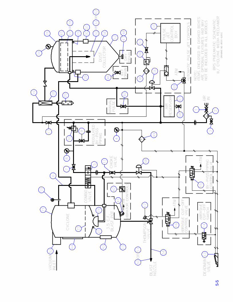
The function of the BRS unit is to blast and recover abrasive media. The BRS is designed to
blast, vacuum, or blast and vacuum simultaneously. The media is contained in the pressure vessel
for blasting. After blasting, media is recovered in the media reclaimer by means of a pneumatic
vacuum system. Small particles are carried by the vacuum air stream into the dust collector. The
media and large particles (paint chips, cigarette butts, etc) drop to the bottom of the media
reclaimer. The media is reloaded at atmospheric condition from the media reclaimer into the
pressure vessel after passing through a screen.
This manual contains part identification numbers (#) within the text that are found on the
drawings in section 5.0, page #5-3 thru #5-15. Refer to these drawings as needed while reading
this manual.
2.1 AIR SUPPLY
Compressed air is supplied through a hose connection and passes through the inlet ball valve
(#1). Then it goes through the moisture separator (#2). The moisture separator has a ball valve
(#3) located at the bottom to drain the moisture collected. During operation this ball valve (#3)
should be slightly open so that the moisture collected can drain. After passing through the
moisture separator the air supply branches into various locations. The first location is the air
supply for the pulse jet system. The second location is the air supply for the media vibrator
(optional). The third location is the vessel pressurization piping which includes the combo valve
and the blast air line. The last location is the air supply for the vacuum system.
2.2 VESSEL PRESSURIZATION PIPING
2.2.1 Combo Valve
The vessel pressurization is controlled by the combo valve (#5). The combo valve is dual
function valve that is essential in the blowdown and blasting operations. On one end, it is a valve
that pinches a 3/4" blowdown hose (#6) to close the vessel and allow pressurization, and releases
the hose to depressurize the vessel. The air released during depressurization escapes into the
media reclaimer through the blowdown hose (#6). Note that there is an orifice (#55) installed in
the blowdown line which prevents the blowdown air from overpowering the vacuum in the media
reclaimer. The other end of the combo valve is a on-off type valve for the air supply to pressurize
the vessel and for blasting. The two functions operate simultaneously when the deadman lever
(#13) is depressed, allowing remote vessel pressurization/blast initiation and vessel
depressurization/blast termination. The minimum pressure to open the combo valve is 55 psig.
2.2.2 Regulated Bypass Piping
An optional feature of the BRS is the regulated bypass piping whose function is to allow blasting
at lower pressures. To activate the regulated bypass controls simply close ball valve (#9), then
the vessel/blast pressure can be adjusted by the pressure regulator (#10) located upstream of the
combo valve. Turn the knob clockwise to increase the pressure and counter-clockwise to reduce
the pressure. To resume full pressure blasting open the ball valve (#9).

2-2
2.3 BLAST AIR LINE
2.3.1 Choke Valve
The choke valve (#11) is a ball valve located in blast air line upstream of the automatic air valve
and Thompson Valve. The function of the choke valve is to aid in the removal of any obstruction
that may, despite all effort, find its way into the blast pot. Whenever a large particle (paint chip,
cigarette butt, etc.) obstructs the Thompson Valve the procedure is to open the Thompson Valve
to the fully open position and then close the choke valve completely for about one second while
the deadman lever (#13) is depressed. If the BRS is equipped with the abrasive cut-off feature
set the switch (#14) to the on-position for the choke procedure. This should be sufficient to
dislodge whatever foreign material that may have obstructed media flow through the Thompson
Valve. The choke valve should be left in the full open position on all other occasions.
2.3.2 Automatic Air Valve
The automatic air valve (#58) is a normally closed pneumatically operated air valve. The normal
function of the air valve is the supply of blast air when the deadman lever (#13) is depressed.
However, in the BRS system the automatic air valve (#58) prevents the air in the blast pot from
exhausting through the pop-up piping (#24) and out of the blast hose during vessel blowdown.
This reverse flow is a condition caused by the implementation of the blowdown orifice (#55).
Refer to section 2.2.1.
2.3.3 Thompson Valve
The Thompson Valve (#12) is a dual function valve. First, it is an abrasive metering valve.
Second, it is an on-off valve that blocks or releases abrasive media into the blast air stream.
When it is open the Thompson valve meters through a adjustable orifice. The degree to which
this orifice is open is determined by the turning the knob at the top of the Thompson valve (CW-
close, CCW-open). The Thompson valve is controlled by the deadman valve (#13) via control
valve(s) (#16 and/or #15). Note that if the BRS unit is equipped with the abrasive cut-off feature
(#14), the switch must be set to the on-position for the Thompson valve to open otherwise only
blast air will exit out of the nozzle.
2.3.4 Abrasive Cut-off
An optional feature of the BRS is the abrasive cut-off. The function of the abrasive cut-off is to
allow blasting air without media. To blast with air only set the abrasive cut-off switch (#14) to
the off-position then depress the deadman lever (#13). This will send a control signal to the
combo valve and automatic air valve only. As a result only blast air will exit out of the nozzle.
The abrasive cut-off feature necessitates the addition of a control valve (#16) which provides the
control signal to the Thompson valve independent to that of the combo valve and air valve.
2.4 VACUUM SYSTEM
2.4.1 Pneumatic Vacuum Pump (Eductor)
The vacuum system is used for media recovery during closed blasting (simultaneous blasting
and recovery), or when solely vacuuming media. The principal component of the vacuum system
is the pneumatic vacuum pump (#18). The vacuum pump is powered by a minimum of 150 CFM
of compressed air at 100 psig. To activate the vacuum system open the ball valve (#17) located
in the air supply piping. The vacuum generated by the vacuum pump can be regulated by the
supply ball valve (#17). When closed blasting it may be necessary to reduce the vacuum to
prevent warpage of thin materials. To reduce the level of vacuum, slightly close the ball valve

2-3
(#17) to obtain the desired vacuum. The vacuum pressure is indicated on the pressure gauge
(#34) located on the dust collector (#26). The vacuum pump exhausts air through a muffler (#20)
and into the BRS frame which further muffles the exhaust and diffuses the air velocity. For
varying vacuum applications the pneumatic vacuum pump (#18) can be equipped with a 150,
225, 350, or 440 CFM nozzle (#19) (Refer to section 3.3.2 for procedure to determine the nozzle
size).
2.4.2 Cyclone Media Reclaimer
The function of the media reclaimer (#21) is to receive the media recovered by vacuuming. The
media and other debris enter the media reclaimer at the tangential inlet (#53) which creates a
cyclonic action on the incoming flow (refer to drawing on page #5-7). Large heavier particles
spiral on the outer extreme and are carried to the bottom of the media reclaimer. Small lighter
particles remain in the air stream and are carried from the media reclaimer into the dust collector
(#26). At the bottom of the media reclaimer there is a screen (#22) that prevents debris (paint
chips, cigarette butts, etc.) from passing into the pressure vessel (#23). When blasting is
interrupted, the pressure vessel pop-up valve (#24) opens which allows the media accumulated
in the media reclaimer to fall through the screen and enter the pressure vessel. The screen should
be inspected and cleaned periodically. It can be accessed through the access door (#44) of the
media reclaimer.
2.4.3 Adjustable Air Wash Media Reclaimer
An optional feature of the BRS is the media reclaimer with the adjustable air wash system (refer
to drawing on page #5-7). The air wash reclaimer is a two stage media separator. The first stage
operates as described above for the cyclone media reclaimer where the primary media separation
occurs at the bottom of the upper cylinder (a). The remaining debris and media falls downward
through the conical orifice (b). At this point smaller particles are washed from the media by the
vacuum flow into the cone tube (c) and flows into the dust collector through the reclaimer outlet
(d). The vacuum intensity at the cone tube is adjusted by the urethane cone tube plug (e). The
adjustment is made by loosening the collar screw (f) and raising or lowering the urethane cone
tube plug. Raising the urethane plug increases the air wash vacuum intensity, while lowering it
decreases the intensity. This adjustment is necessary to optimize dust removal while also
minimizing removal of good media. At the bottom of the media reclaimer there is a screen (#22)
mounted on vibration isolators (#66) that prevents debris (paint chips, cigarette butts, etc.) from
passing into the pressure vessel (#23). Located on the screen is a media vibrator (#61) to aid in
media flow through the screen. The screen should be inspected and cleaned periodically. It can
be accessed through the access door (#44) of the media reclaimer.
2.4.4 Dust collector
The dust-filled vacuum air stream from the media reclaimer enters the dust collector (#26) where
the dust particles are filtered out by one of three available methods (wet filtration, dry filtration
or HEPA filtration). The clean vacuum air stream is evacuated from the dust collector through
the vacuum pump (#18).
2.4.4.1 Wet filtration
The first viable method of filtration by the dust collector (#26) is wet filtration. This
method pulls the dust-filled air stream through water which traps the dust particles. After
rising through the water, the air stream passes through a stainless steel demister filter
(#27) to remove any water droplets that may have mixed with the air stream. The demister

2-4
filter is a removable component that fits in the box section of the dust collector through
the latched door (#45). After sliding the demister filter (#27) into the box section, close
and latch the door, then push it into position with the four retractable locators (#29). The
dust collector is filled with water through a 2" connection (#31) up to the bottom of the
connection. The water in the dust collector should be changed periodically. The ideal time
to do so is at the end of the work day before the dust has settled to the bottom. The water
can be drained through the ball valve (#46) at the bottom of the dust collector. The dry
filter and HEPA filter (if so equipped) must be removed from the dust collector prior to
operating with wet filtration.
2.4.4.2 Dry filtration
The second optional method of filtration is dry filtration. This method utilizes a pleated
filter that fits in the round section of the dust collector. The dry filter [10"(#62), 12"(#32)
or 18"(#33)] is installed through the latched bottom head (#52) of the dust collector. The
filter is held in position by the wingnut (#56) which seals it against the bottom of the box
section of the dust collector. The dry filter must be pulsed regularly during operation to
prevent clogging (see section 2.5). In addition the filter must be periodically cleaned to
insure long life (see section 4.4.3).
2.4.4.3 HEPA filtration
When particulate free exhaust air is required, the optional HEPA (High Efficiency
Particulate Air ) filter (#28) can be installed. The HEPA filter is tested by DOP method
to be 99.97% efficient on particles 0.3 microns in size or larger. In this arrangement the
air passes through the dry filter (#32, #33 or #62), then passes through the HEPA filter
before exhausting. The HEPA filter fits in the box section of the dust collector through
the latched door (#45). After sliding the HEPA filter into the box section, close and latch
the door, then push it into position with the four retractable locators (#29). This seals the
filter against the bottom of the box section of the dust collector. The dry filter (#32, #33
or #62) must be used in conjuction with the HEPA filter.
2.5 PULSE JET SYSTEM
The function of the pulse jet system is to prevent clogging of the dry filter (#32, #33 or #62) by
periodically providing a burst of air inside the filter to loosen dust particles from the pleated
surface. This is accomplished manually or by the optional automatic pulse jet controls. The
required interval between pulses is determined by the blasting conditions. As the particles begin
to clog the filter the vacuum pressure within the dust collector will increase. This increase can
be detected on the pressure gauge (#34). The pulsing air supply utilizes a reservoir (#67) to
prevent pressure drops at the blast nozzle. The reservoir has a ball valve (#68) located at the
bottom to drain the moisture collected. During operation this ball valve (#68) should be slightly
open so that the moisture collected can drain.
2.5.1 Manual Pulse
The manual pulse process is totally operator dependant and requires consistent operation
to insure trouble free vacuum filtration. The manual pulse requires the operator to
periodically open the ball valve (#40) for a fraction of a second which provides the burst
of air to loosen entrapped particles. The pulse should be actuated regularly during closed
blasting (blasting w/vacuum recovery) and may require a second operator.

2-5
2.5.2 Automatic pulse jet controls
The automatic pulse system provides operator-free pulsing of the dry filter and operates
only when the vacuum pump (#19) is powered. The automatic pulse jet is controlled by
a pneumatic oscillator (#59) located in the pulse air control box (#35) (refer to drawing
in section 5.0, page #5-8). Upstream of the pulse air control box an air filter (#38) and
a non-adjustable regulator (#39) are installed to maintain the clean air, of a maximum of
80 psig, required by the pulse controls. The pulse air control box sends a signal to an
automatic air valve (#36), via a control valve (#60), which opens providing the burst of
air necessary to unclog the dry filter (#32, #33 or #62). The adjustment of the pulse air
control box is dictated by the blasting conditions. The interval between pulses is adjusted
by the upper knob (T1) on the oscillator (#59). The pulse length is adjusted by the lower
knob (T2). The pulse effect can be seen by a decrease in the vacuum reading on the
pressure gauge (#34). The automatic pulse jet controls can be disabled by closing the ball
valve (#37). In addition, manual pulsing can be applied by opening the three-way ball
valve (#69) which sends an air signal to the automatic air valve (#36). The purpose of this
feature is to allow pulsing to clean the dry filter without the operation of the vacuum
pump.
2.6 MEDIA VIBRATOR (vessel)
The media vibrator (#41) is an optional feature whose function is to vibrate the media in the
pressure vessel (#23) which creates better media flow characteristics. The level of vibration is
controlled by the angle valve (#42) which can also turn off the vibration.
2.7 MEDIA VIBRATOR (media screen)
The air wash media reclaimer is equipped with a screen mounted vibrator to increase flow
through the screen (refer to drawing on page #5-7). The level of vibration is controlled by the
angle valve (#63) which can also turn off the vibration. The vibrator can be accessed by removing
the screen through the access door (#44).
2.8 BLAST HOSE ASSEMBLY
The size of the blast hose is determined by the size nozzle to be used. Generally the blast hose
inside diameter should be three times the nozzle throat diameter. For open cycle blasting (without
vacuum recovery) conditions and preference dictate the size nozzle/hose combination to be used.
However, to utilize closed cycle blasting which requires the BRS vacuum head, only a 3/4" blast
hose assembly can be used. This is due to the limitations inherent to this type of blasting which
require size constraints designed into the BRS vacuum head. The use of a 3/4" blast hose implies
that the largest size nozzle that can be used during closed cycle blasting is a #4 (1/4"), but a #5
(5/16") can also be used effectively.
2.9 BLAST NOZZLE
While blasting, the blast air/media mixture flows through the blast hose (#54) to the blast nozzle
(# 51). The blast nozzle throat diameter directly affects the air flow rate, media flow rate, and

2-6
surface removal rate. Nozzles come in several sizes which can be identified by a small number
visible on the nozzle. This number represents the nozzle throat diameter size in sixteenths of an
inch; for example, a #5 nozzle has a throat diameter of 5/16". The best nozzle size for a particular
application can be determined by several factors:
i. How much compressed air is available? Refer to section 6.0, table 1 for the approximate
air consumption for each size blast nozzle
ii. Will blasting be done open cycle (w/o vacuum recovery) or closed cycle (w/simultaneous
vacuum recovery)? When closed blasting, the blast air flow must not be greater than the
vacuum pump (#18) capacity. This will prevent blast air and dust from blowing out
around the nozzle brushes on the BRS vacuum head (#50). The recommended blast
nozzle size to be used in closed blasting varies depending on the length and diameter of
the vacuum hose. Use the following general guidelines for reference:
BLAST PRESSURE NOZZLE SIZE
15 psi or less #7 Nozzle
30 psi or less #6 Nozzle
50 psi or less #5 Nozzle
100 psi or less #4 Nozzle
Open blasting (w/o vacuum recovery) can be done with any size nozzle, but for higher
production a #8 (1/2") nozzle is most commonly used.
iii. What type of surface is being blasted? Blasting small or intricate parts is usually done
with a smaller nozzle.
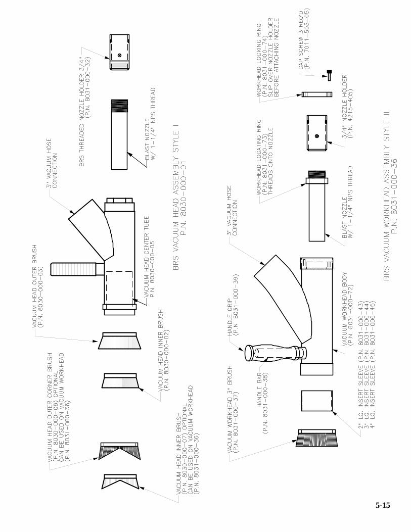
2.10 BRS VACUUM HEAD
The vacuum head (#50 or #64) is used when operating in the closed blasting mode (blasting with
simultaneous vacuum recovery). The blast media is contained within the vacuum head where
from it is recovered by the vacuum system. The blast nozzle (#51) screws into the nozzle
holder (#54) of the blast hose assembly, which in turn fits into the BRS vacuum head (#50 or
#64). Then the suction hose attaches to the side of the vacuum head. The vacuum hose to BRS
head is usually a tight fit, so no further seal is required at that joint. All other joints in the vacuum
line are sealed with hose clamps. There are two style vacuum heads that are used with the BRS
(refer to the drawings on page #5-15), each is equipped with brushes and a center wear tube that
attach to the working end of the head. The brushes and center tube are wear components and
should be inspected and replaced periodically. When operating in the closed blasting mode
requiring the use of a vacuum head assembly, it is important to remember that this limits the size
of blast nozzle (#51) that can be used due to limitations created by the blast head and the
available compressed air volume. Refer to section 3.3 to determine compressed air requirements.

3-1
3.0 OPERATING PROCEDURE
This section contains part identification numbers (#) within the text that are found on the
drawings in section 5.0, pages #5-3 thru #5-15. Refer to these drawings as needed while reading
this manual. Prior to operating the BRS unit, carefully read the safety warnings in section 0.0.
3.1 OPEN CYCLE BLASTING (blasting without vacuum recovery)
3.1.1 Unit Set Up:
3.1.1.1 To prevent static electricity shocks to operating personnel, the BRS unit must
be grounded.
3.1.1.2 Close the air inlet ball valve (#1), the pneumatic vacuum pump ball valve (#17),
the vessel pressurization ball valve (#7), the media vibrator valve (#42 if so
equipped), media screen vibrator valve (#63 if so equipped) and the pulse jet
ball valve(s) (#37 & #69, or #40).
3.1.1.3 Make sure the handway (#43) on the blast pot (#23) is closed and tightened.
3.1.1.4 Remove BRS vacuum head (#50 or #64) from blast hose assembly.
3.1.1.5 Screw a standard long venturi nozzle (#51) into the nozzle holder (#54) of the
blast hose assembly.
3.1.1.6 Connect the blast hose (#54) to the coupling on the Thompson valve (#12) and
install safety clips to prevent accidental disconnection during operation.
3.1.1.7 Connect the twinline hose quick connects (#57) to the mating quick connects
on the control valve(s) (#16 and/or #15).
3.1.1.8 Connect the vacuum hose assembly to the vacuum inlet (#53).
3.1.1.9 Connect an air supply hose to the air inlet crowfoot on the BRS and install safety
clips to prevent accidental disconnection during operation. Refer to section 3.3
to determine the compressed air requirements. Note that the pneumatic vacuum
pump consumes air in addition to the air requirements of the blast nozzle. The
amount of air consumed by the pump depends on the vacuum pump nozzle size
(150, 225, 350 or 440 CFM). Refer to section 3.3.2 to determine the nozzle size.
3.1.1.10 If the blast pot is already full of media skip to section 3.1.2. To fill the blast pot
disconnect the vacuum hose from the BRS vacuum head (#50 or #64).
3.1.1.11 Make sure the handway and doors (#43, #44, #45 & #52) on blast pot (#23),
media reclaimer (#21) and dust collector (#26) are closed tight.
3.1.1.12 Open the air inlet valve (#1).
3.1.1.13 Open valve (#17) to turn on vacuum pump (#19).

3-2
3.1.1.14 Vacuum desired amount of media into the blast pot (#23). Do not overfill, for
this will cause media overflow into the dust collector when blasting with
vacuum recovery (refer to section 1.1 for capacity). If the media being used
is low density, it may be necessary to reduce the vacuum to prevent carryover
of new media into the dust collector. The vacuum generated by the vacuum
pump (#18) can be regulated by the supply ball valve (#17). To reduce the
level of vacuum, slightly close the ball valve (#17). Note: If the unit is
equipped with an adjustable air wash media reclaimer, the vacuum intensity
at the cone tube (c) may also require adjustment. Refer to section 2.4.3.
3.1.1.15 Close valve (#17) to turn off vacuum pump (#19).
3.1.2 Open Cycle Blasting Operation:
3.1.2.1 After completion of the procedures in section 3.1.1, the BRS unit is now ready
for open cycle blasting (blasting without simultaneous vacuum recovery).
3.1.2.2 Open the air inlet ball valve (#1).
3.1.2.3 Set your desired tank/blast pressure (if so equipped) by turning the pressure
regulator (#10) knob clockwise for higher pressure or counterclockwise for
lower pressure. Remember that when blasting, the pressure indicated on the
pressure gauge (#8) will drop slightly.
3.1.2.4 To operate at full pressure, without the regulator restriction, open ball valve
(#9).
3.1.2.5 Partially open the drain ball valves (#3 & #68) at the bottom of the moisture
separator (#2) and reservoir (#67) to allow accumulated moisture to drain. This
prevents moisture from entering the blast pot (#23) and dust collector (#26)
during blasting.
3.1.2.6 Open the Thompson Valve (#12) slightly. The best setting for this valve differs
from one situation to another; therefore, it may take more than one adjustment
to achieve the desired air/media mixture. Turn the Thompson Valve knob
clockwise to decrease media flow or counterclockwise to increase media flow.
3.1.2.7 Turn on vessel media vibrator (#41 if so equipped) and set to the desired level
of vibration by adjusting the angle valve (#42).
3.1.2.8 If the unit is equipped with an adjustable air wash media reclaimer, turn on
media screen vibrator (#61) and set to the desired level of vibration by adjusting
the angle valve (#63).
3.1.2.9 Open the choke valve (#11) and vessel pressurization ball valve (#7).
3.1.2.10 Depress the pneumatic deadman lever (#13) to begin blasting. Note that if the
BRS is equipped with the abrasive cut-off feature, switch (#14) must be set to
the “on” position to blast with media.

3-3
3.2 CLOSED CYCLE BLASTING (blasting with vacuum recovery)
This section contains part identification numbers (#) within the text that are found on the
drawings in section 5.0, pages #5-3 thru #5-15. Refer to these drawings as needed while reading
this manual. Prior to operating the BRS unit, carefully read the safety warnings in section 0.0.
3.2.1 Unit Set Up:
Wet Filtration
3.2.1.1 To prevent static electricity shocks to operating personnel, the unit must be
grounded.
3.2.1.2 Open valve (#46) to drain water mixed with spent media out of dust collector
(#26).
3.2.1.3 Close valve (#46).
3.2.1.4 Be sure there are no dry filters (#28, #32, #33 or #62) installed in the dust
collector. Then remove water fill dust cap (#31) on dust collector and fill with
water until the level reaches the bottom of the coupling.
3.2.1.5 Reinstall water fill dust cap (#31).
3.2.1.6 Open the latched door (#45) of the box section of the dust collector. Install the
stainless steel demister filter (#27). Close and latch the door (#45) the raise the
demister into position with the four retractable locators (#29). Skip to step
3.2.1.12 .
Dry Filtration
3.2.1.7 To prevent static electricity shocks to operating personnel, the unit must be
grounded.
3.2.1.8 Remove drain dust cap (#48) at the bottom of the dust collector (#26) to drain
the spent media.
3.2.1.9 Reinstall the drain dust cap (#48).
3.2.1.10 Open the hinged head (#52) of the dust collector. Install the dry filter [10"
(#62), 12" (#32) or 18" (#33)] in the round section of the dust collector (#26)
and secure in position with the wingnut. Close and latch the hinged head (#52).
3.2.1.11 Open the latched door (#45) on the box section of the dust collector. Install the
HEPA filter (#28 if so equipped). Close and latch the door (#45) then raise the
filter into position with the four retractable locators (#29).
3.2.1.12 Close the air inlet ball valve (#1), the pneumatic vacuum pump ball valve (#17),
the vessel pressurization ball valve (#7), the vessel media vibrator valve (#42
if so equipped), media screen vibrator valve (#63 if so equipped) and pulse jet
ball valve(s) (#37 & #69, or #40).

3-4
3.2.1.13 Make sure the handway (#43) on the blast pot (#23) is closed and tightened.
3.2.1.14 Screw a standard long venturi nozzle (#51) into the nozzle holder (#54) of the
blast hose assembly.
3.2.1.15 Connect the BRS vacuum head (#50 or #64) to the nozzle holder (#54) of the
blast hose assembly. Refer to drawing on page #5-15.
3.2.1.16 Connect the blast hose (#54) to the coupling on the Thompson valve (#12) and
install safety clips to prevent accidental disconnection during operation.
3.2.1.17 Connect the twinline hose quick connects (#57) to the mating quick connects
on the control valve(s) (#16 and/or #15).
3.2.1.18 Connect the vacuum hose assembly to the vacuum inlet (#53).
3.2.1.19 Connect an air supply hose to the air inlet crowfoot on the BRS and install safety
clips to prevent accidental disconnection during operation. Refer to section 3.3
to determine the compressed air requirements. Note that the pneumatic vacuum
pump consumes air in addition to the air requirements of the blast nozzle. The
amount of air consumed by the pump depends on the vacuum pump nozzle size
(150, 225, 350 or 440 CFM). Refer to section 3.3.2 to determine the nozzle size.
3.2.1.20 If the blast pot is already full of media, skip to section 3.2.2. To fill the blast pot
disconnect the vacuum hose from the vacuum head (#50 or #64).
3.2.1.21 Make sure the handway and doors (#43, #44, #45 & #52) on blast pot (#23),
media reclaimer (#21) and dust collector (#26) are closed tight.
3.2.1.22 Open the air inlet valve (#1).
3.2.1.23 Open valve (#17) to turn on vacuum pump (#19).
3.2.1.24 Vacuum desired amount of media into the blast pot (#23). Do not overfill, for
this will cause media overflow into the dust collector while blasting with
vacuum recovery (refer to section 1.1 for capacity). If the media being used
is low density, it may be necessary to reduce the vacuum to prevent carryover
of new media into the dust collector. The vacuum generated by the vacuum
pump (#18) can be regulated by the supply ball valve (#17). To reduce the level
of the vacuum, slightly close the ball valve (#17). Note: If the unit is equipped
with an adjustable air wash media reclaimer, the vacuum intensity at the cone
tube (c) may also require adjustment. Refer to section 2.4.3.
3.2.1.25 Close valve (#17) to turn off vacuum pump (#19).
3.2.1.26 Re-attach vacuum hose to the BRS vacuum head (#50 or #64)).

3-5
3.2.2 Closed Cycle Blasting Operation
3.2.2.1 After completion of the procedures in section 3.2.1, the BRS unit is now ready
for closed cycle blasting (blasting with simultaneous vacuum recovery).
3.2.2.2 Open air inlet ball valve (#1).
3.2.2.3 Set your desired tank/blast pressure (if so equipped) by turning the pressure
regulator (#10) knob clockwise for higher pressure or counterclockwise for
lower pressure. Remember that when blasting, the pressure indicated on the
pressure gauge (#8) will drop slightly.
3.2.2.4 To operate at full pressure, without the regulator restriction, open ball valve (#9).
3.2.2.5 Partially open the drain ball valves (#3 & #68) at the bottom of the moisture
separator (#2) and reservoir (#67) to allow accumulated moisture to drain. This
prevents moisture from entering the blast pot (#23) and dust collector (#26)
during blasting.
3.2.2.6 Open the Thompson Valve (#12) slightly. The best setting for this valve differs
from one situation to another; therefore, it may take more than one adjustment
to achieve the desired air/media mixture. Turn the Thompson Valve knob
clockwise to decrease media flow or counterclockwise to increase media flow.
3.2.2.7 Open valve (#17) to turn on vacuum pump.
3.2.2.8 Before blasting, inspect the brushes on the BRS vacuum head (#50) and replace
any that are worn or damaged.
3.2.2.9 Place the BRS vacuum head (#50) against the surface to be blasted until the
brushes seal against the blasting surface. The vacuum gauge (#34) on the dust
collector (#26) should read about _ to 4" Hg.
3.2.2.10 Turn on media vibrator (#41 if so equipped) and set to the desired level of
vibration by adjusting the angle valve (#42).
3.2.2.11 If the unit is equipped with an adjustable air wash media reclaimer, turn on
media screen vibrator (#61) and set to the desired level of vibration by adjusting
the angle valve (#63).
3.2.2.12 Open the choke valve (#11) and vessel pressurization ball valve (#7).
3.2.2.13 Set the automatic pulse (if so equipped) to the desired level (refer to section 2.5).
The optimum setting varies depending on blast conditions therefore more than
one adjustment may be needed.
3.2.2.14 Depress the pneumatic deadman lever (#13) to begin blasting. Note that if the
BRS is equipped with the abrasive cut-off feature, switch (#14) must be set
to the “on” position to blast with media.

3-6
3.3 COMPRESSED AIR REQUIREMENTS
3.3.1 Blast nozzle
One of the primary air expenditures is by the blast nozzle. This expenditure can vary
greatly depending upon the nozzle size and the blast pressure. See section 6.0 table 1 for
air consumption by nozzle size at various pressures.
3.3.2 Pneumatic vacuum pump nozzle
The BRS unit uses a pneumatic vacuum pump in its recovery system. The amount of air
consumed by the pneumatic vacuum pump is determined by the vacuum pump nozzle
size. The pneumatic vacuum pump nozzle can be one of four different sizes (150, 225,
350, or 440 CFM). At the time of manufacturing, a decal is placed on the exhaust muffler
(#20) that identifies the size of the vacuum pump nozzle. If the decal is not present on
the unit, the vacuum pump nozzle size can be found stamped on the flange of the nozzle
(#19). The nozzle can be removed through the pipe tee located at the pump air inlet (#18)
by first removing the pipe plug from the tee.
Note: On units manufactured prior to June 1998, the vacuum pump nozzle (#19) can be
accessed by loosening the 2" pipe union located near the air inlet of the vacuum pump
(#18). After loosening the union, remove the 2" elbow with pipe nipple to view or remove
the vacuum pump nozzle.
3.3.3 Air compressor size
The air compressor must be large enough to supply:
i. Blast air for the largest nozzle and the highest pressure that will be used (see
section 6.0 table 1).
ii. The air requirement dictated by the pneumatic vacuum pump nozzle size.
iii. The 12 CFM breathing air supplied to the blast hood when open blasting.
Since the pneumatic vacuum pump consumes a minimum of 150 CFM at 100 psig, the
air supply hose from the air compressor to the BRS unit should be at least 1 1-2" in
diameter. This size hose will supply the necessary air flow to simultaneously operate the
vacuum pump and blast nozzle.

4-1
4.0 NORMAL MAINTENANCE
This section covers maintenance that should be performed at regular intervals to insure proper
operation of the BRS unit. All the procedures discussed in this section should be performed with
the BRS unit completely depressurized and the air supply hose disconnected. Refer to the
drawings in section 5.0 to aid in the completion of any maintenance.
4.1 Combo valve
The black hose (#6) that passes through the combo valve (#5) is a 3/4" blast hose. Media carry-
over can abrade a hole through the wall of the hose. Simply replace the hose with another section
of hose, but make sure that the hose does not make any tight bends anywhere between the blast
pot and the cyclone because this will cause the wear to be much more rapid. Periodically check
the blowdown orifice (#55) for wear. Excessive wear of the orifice can allow the blowdown air
to overpower the cyclone vacuum.
4.2 Thompson valve
If a blast nozzle will not shut off completely, it is probably because of a worn Thompson valve
seat. It is replaced by unbolting the base of the valve (when the BRS unit is depressurized).
4.3 Cyclone/Air wash media reclaimer
The media screen inside the media reclaimer can accumulate debris therefore it should be
periodically checked and cleaned. It can be accessed through the access door (#44).
4.4 Dust collector
4.4.1 Wet filtration
When operating with wet filtration the water in the dust collector becomes contaminated with
spent media, therefore the water should be drained regularly. The ideal time to do so is at the
end of the work day before the dust has settled to the bottom. This is accomplished by opening
the drain ball valve (#46). Refill the dust collector through the 2" connection (#31) until the water
level reaches the bottom of the coupling.
4.4.2 Dry filtration
When operating with dry filtration the spent media accumulates in the bottom of the dust
collector, therefore it must be drained periodically. This is accomplished by removing the drain
dust cap (#48).
4.4.3 Dry filter cleaning
To achieve the longest life of the dry filter it is important that they be serviced regularly. The
following methods are recommendations to assist in cleaning BRS dry filters. The first three are
for both paper element filters and polyester element filters. However, be aware that the washing
method is for polyester element filters only.
4.4.3.1 Manual pulsing
The first cleaning step should be manual pulsing. This is done by opening the manual
pulse ball valve (#40 or #69) to provide a burst of air inside the filter to loosen dust
particles from the pleated surface. Also manual pulse during periods of blast stoppage.
4.4.3.2 Vacuuming method
The second cleaning method to utilize is vacuuming. A commercial duty vacuum cleaner
4-2
is recommended, but a common household type may also be used. Vacuum the filter from
the air intake (contaminated) side only. This procedure will remove the majority of the
large particles and surface contaminants that have accumulated and may be sufficient for
the first cleaning of the filter. This step should also be performed prior to progressing to
any subsequent cleaning method.
4.4.3.3 Compressed air method
The third cleaning step is by use of compessed air. The air flow must be directed from
the opposite direction of the normal air flow through the filter. The air flow should be
directed up and down the pleats. Do not direct the flow in a criss-crossing pattern across
the direction of the pleats this could cause damage to paper element filters and decreases
cleaning efficiency.
4.4.3.4 Washing method (polyester element filter only)
The washing process is for polyester element filters only. The final cleaning process may
be necessary to reduce the static pressure to an acceptable level when the filter has fine
particles that have become imbedded in the filter element. For this procedure a mild low
sudsing detergent should be used with clean warm water. Soak the filter for 5-10 minutes,
then gently agitate the filter for several minutes. The filter should then be thoroughly
rinsed with clean water to remove the detergent. It may require a second or third washing
to obtain satisfactory filtration. However, the dirt holding capacity of the filter decreases
after each washing.
Critical: Do not attempt to wash dry filters with paper elements, this will render them
useless. If you are not certain of the type of element seek assistance.
Note: Polyester element filters can be washed and reused under proper conditions.
However, Axxiom / Schmidt has no control over the washing process and cannot
guarentee that it has been performed properly and effectively, therefore our warranty does
not apply to washed filters.
4.4.3.5 Inspection
Inspecting the filter after each cleaning is vital. A simple method of inspection is to use
a light bulb. Light passing through the filter will reveal fatigued paper or dirt
accumulations. Inspection should also include the end plates to check for possible
damages during handling. Inspect for damage that could allow contaminated air to bypass
the filter element.
4.5 Vacuum Head
As the inner and outer brushes of the vacuum head wear they will loose there sealing capabilities,
therfore they should be replaced after approximately 25 hours of use. In addition, the vacuum
head contains a inner wear tube to prevent the abrasive from wearing through the body of the
vacuum head. This wear tube should be inspected periodically and replaced after approximately
25 hours of use. Refer to drawings on page #5-15.
4.6 Remaining Components
Most of the BRS components are subject to wear and therefore it is expected that they will
eventually require maintenance, but those not mentioned above should not need to be part of a
periodic maintenance program.

5-1
5.0 PARTS LISTThis section contains a parts breakdown covering all the major components which may requiremaintenance during operation of the BRS. The major items identified in the parts list are foundon the drawings on pages #5-3 thru #5-15. Refer to these drawings as needed while reading thismanual. In addition, repair kits to rebuild these items are identified and drawings are providedto aid in disassembly and installation of the new parts.
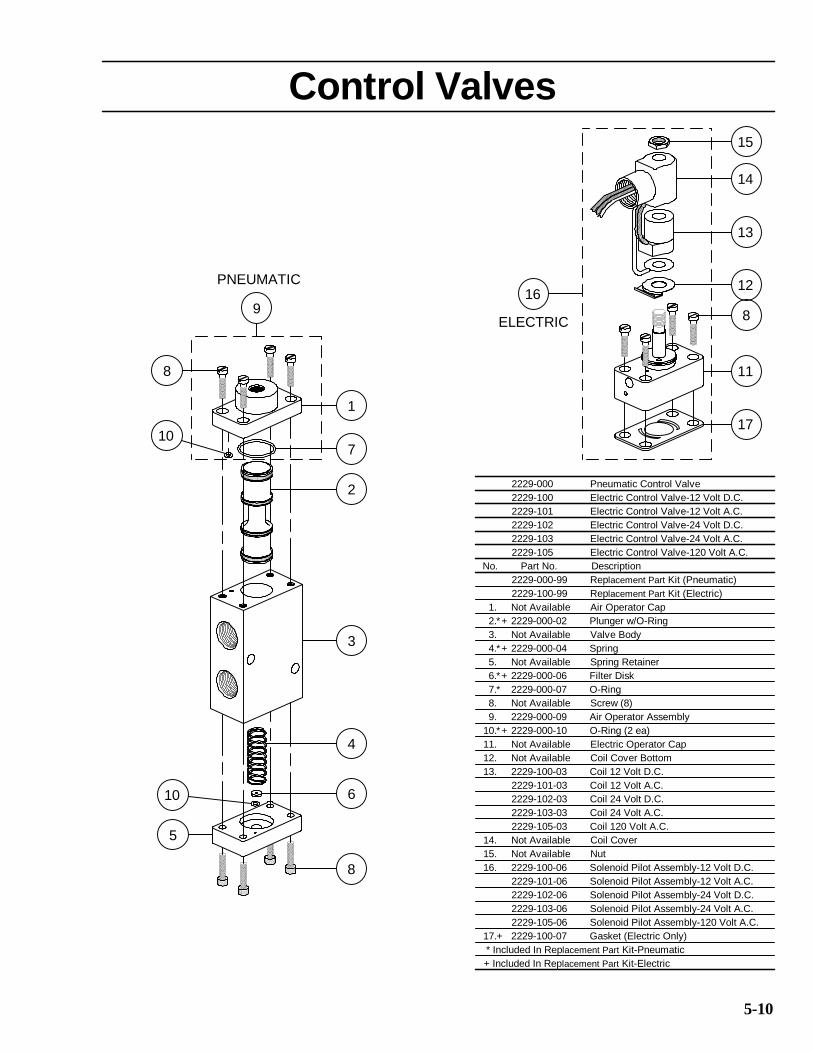
ITEM PART NUMBER DESCRIPTION 1. 2401-509 Ball valve, full port 2" 2. 1200-999-23 Moisture separator, 2" x 2" 3. 2401-502 Ball valve, full port 1/4" 4. 2010-009-01 Pressure gauge, 0-160 psi 5. 2223-000 Combo valve, 1-1/4" 6. 4104-005 Hose, 4-ply 3/4" (specify length) 7. 2401-507 Ball valve, full port 1-1/4" 8. 2010-009-01 Pressure gauge, 0-160 psi 9. 2401-507 Ball valve, full port 1-1/4" 10. 2003-007 Air regulator, 1-1/4" 11. 2401-507 Ball valve, full port 1-1/4" 12. 2149-107 Thompson valve, urethane 1-1/4" 13. 2263-000 Deadman valve, pneumatic 14. 2025-010 Abrasive cutoff switch, pneumatic 15. 2229-000 Control valve, pneumatic 16. 2229-000 Control valve, pneumatic 17. 2401-507 Ball valve, full port 1-1/4"
2401-509* Ball valve, full port 2" * 18. 2018-011 Eductor, urethane 3" 19. 2018-111-01 Eductor nozzle, 150 cfm
2018-211-01 Eductor nozzle, 225 cfm2018-311-01 Eductor nozzle, 350 cfm2018-411-01 Eductor nozzle, 440 cfm
20. 2011-011 Muffler assembly, 3" 21. 8031-020-04 BRS 2.0 cyclone media reclaimer
8031-030-04 BRS 3.5 cyclone media reclaimer8031-060-04 BRS 6.5 cyclone media reclaimer8031-020-05 BRS air wash media reclaimer
22. 8031-000-34 BRS cyclone reclaimer media screen8031-000-75 BRS adjustable air wash reclaimer media screen
23. 8031-020-01 BRS 2.0 cf pressure vessel8031-030-01 BRS 3.5 cf pressure vessel8031-060-01 BRS 6.5 cf pressure vessel
24. 2100-010 Pop-up head, 3 & 6 bag vessel 25. 2100-011 Pop-up gasket, 3 & 6 bag vessel 26. 8031-020-02 BRS 2.0 dust collector
8031-030-02 BRS 3.5 & 6.5 dust collector 27. 8031-000-68 BRS demister filter, 18" X 18"
8031-000-12 BRS demister filter, 24" X 24" 28. 8031-000-40 BRS hepa filter, 18" x 18"
8031-000-11 BRS hepa filter, 24" x 24" 29. 8031-000-05 BRS filter retractable locator 30. 4222-409 Camlock coupling, type f 2" 31. 4223-409 Camlock coupling, type dc 2" 32. 8031-000-09 BRS dry filter, 12" polyester element
8031-000-24 BRS dry filter, 12" paper element8031-000-83 BRS dry filter, 12" high output
33. 8031-000-10 BRS dry filter, 18" polyester element8031-000-25 BRS dry filter, 18" paper element
34. 2010-026 Pressure gauge, 30 vac-0-15 psi
*On units manufactured prior to June, 1998 vacuum pump air supply valve (#17) was 2".

5-2
35. 8031-000-17 BRS pulse air control box 36. 2123-106 Automatic air valve, n.c. 1"
2123-107 Automatic air valve, n.c. 1-1/4" 37. 2401-502 Ball valve, full port 1/4" 38. 2302-102-05 Air filter, 1/4" 5 micron 39. 2001-010 Regulator, non-adjustable 1/4" 40. 2401-507 Ball valve, full port 1-1/4" 41. 2020-013 Vibrator, 2.0 vessel
2020-025 Vibrator, 3.5 & 6.5 vessel 42. 2430-804 Angle valve, 1/4" 43. 7000-001-11 Handway crab assembly, 6" x 8"
7000-001-06 Handway gasket, 6" x 8"7000-000-11+ Handway crab assembly, 4" x 6" +7000-000-06+ Handway gasket, 4" x 6" +
44. 8031-000-77 BRS 2.0 cyclone reclaimer door gasket8031-000-31 BRS 3.5 & 6.5 cyclone reclaimer door gasket8031-000-71 BRS air wash reclaimer door gasket
45. 8031-000-70 BRS 2.0 dust collector door gasket8031-000-04 BRS 3.5 & 6.5 dust collector door gasket
46. 2401-507 Ball valve, full port 1-1/4" 47. 4222-411 Camlock coupling, type f 3"
4222-413 Camlock coupling, type f 4" 48. 4223-411 Camlock coupling, type dc 3"
4223-413 Camlock coupling, type dc 4" 49. 2301-902-90 Strainer, bronze 1/4" 90 micron 50. 8030-000-01 BRS vacuum head, 3" style I
8030-000-02 Vacuum head inner brush8030-000-03 Vacuum head outer brush8030-000-05 Vacuum head center tube
51. 5000-xxx Blast nozzle (specify size) 52. 8031-000-69 BRS 2.0 dust collector head gasket
8031-000-03 BRS 3.5 & 6.5 dust collector head gasket 53. 4212-010 K.C. nipple, 2-1/2"
4212-011 K.C. nipple, 3" 54. 4104-40x-0x Blast hose (specify size and length)
8031-000-32 BRS threaded nozzle holder (to fit item #50) 55. 8031-000-28 BRS blowdown orifice 56. 8031-000-27 BRS filter wingnut 57. 4224-300-02 Quick connect plug, 1/4"
4224-301-02 Quick connect socket, 1/4" 58. 2123-107 Automatic air valve, n.c. 1-1/4" 59. 8031-000-18 BRS pulse air pneumatic oscillator 60. 2229-000 Control valve, pneumatic 61. 2020-013 Vibrator, media screen 62. 8031-000-67 BRS dry filter, 10" polyester element
8031-000-41 BRS dry filter, 10" paper element 63. 2430-804 Angle valve, 1/4" 64. 8031-000-36 BRS vacuum workhead, 3" style II
8031-000-37 Vacuum workhead brush, 3"8031-000-43 Vacuum workhead insert sleeve, 2" lg.8031-000-44 Vacuum workhead insert sleeve, 3" lg.8031-000-45 Vacuum workhead insert sleeve, 4" lg.
65. 8031-000-42 BRS vessel screen knob 66. 8031-000-46 BRS screen isolator 67. ----------- Pulse air reservoir 68. 2401-502 Ball valve, full port 1/4" 69. 2403-302 Ball valve, 3-way 1/4"
+On units manufactured prior to November, 1996 handway (#43) was 4" x 6".

5-3

5-4
5-5

5-6

5-7

5-8

20. 2014-300 Vent, 1/8"
5-9
22
21
20
12
8 913
10
18
14
5
11
15
16
19
17
22. 4203-502-02 90° Swivel, 1/4" x 1/4"
21. 4203-500-00 90° Swivel, 1/8" x 1/8"
* Included in replacement part kit
4
7
2
3
61
Combo Valve2223-000 Combo Valve
1. 2223-000-01 Cap
2. 2223-000-02 Pinch Ram
3. 2223-000-03 Upper Rod Guide
4. 2223-000-04 Seal (Upper Rod)
5. 2223-000-05 Spring
6. 7010-507-15 Bolt, 3/8" x 6"
7. 2223-000-07 Cylinder
8. 2223-000-08 O-ring (Shaft)
9. 2223-000-09 Snap Ring
10. 2223-000-10 Seal (Lower Rod)
11. 2223-000-11 Piston
12. 2223-000-12 Shaft
13. 2223-000-13 Piston Seal
14. 7050-507 Nut, 3/8"
15. 2223-000-15 Lower Rod Guide
16. 2223-000-16 O-ring (Lower Rod Guide)
17. 2223-000-17 Base
18. 2223-000-18 Valve Plug Assembly
19. 7019-503 Nut, 1/4"
No. Part No. Description
*
*
*
*
*
*
*
*
2223-000-99 Replacement Part Kit
9
5
10 6
PNEUMATIC
8
4
3
10
2
8
1
14. Not Available Coil Cover
15. Not Available Nut
+
12. Not Available Coil Cover Bottom
11. Not Available Electric Operator Cap
2229-105 Electric Control Valve-120 Volt A.C.
No. Part No. Description
7. 2229-000-07 O-Ring
8. Not Available Screw (8)
9. 2229-000-09 Air Operator Assembly
*
*
*
*
7
2229-103 Electric Control Valve-24 Volt A.C.
13. 2229-100-03 Coil 12 Volt D.C.
10. 2229-000-10 O-Ring (2 ea)
* Included In Replacement Part Kit-Pneumatic
+ Included In Replacement Part Kit-Electric
2229-103-03 Coil 24 Volt A.C.
2229-102-03 Coil 24 Volt D.C.
2229-101-03 Coil 12 Volt A.C.
2229-105-03 Coil 120 Volt A.C.
13
2. 2229-000-02 Plunger w/O-Ring
2229-000-99 Replacement Part Kit (Pneumatic)
4. 2229-000-04 Spring
ELECTRIC
3. Not Available Valve Body
1. Not Available Air Operator Cap
5. Not Available Spring Retainer
6. 2229-000-06 Filter Disk
2229-100-99 Replacement Part Kit (Electric)
2229-100 Electric Control Valve-12 Volt D.C.
2229-102 Electric Control Valve-24 Volt D.C.
2229-101 Electric Control Valve-12 Volt A.C.
2229-000 Pneumatic Control Valve
+
+
*
2229-103-06 Solenoid Pilot Assembly-24 Volt A.C.
2229-102-06 Solenoid Pilot Assembly-24 Volt D.C.
2229-101-06 Solenoid Pilot Assembly-12 Volt A.C.
2229-105-06 Solenoid Pilot Assembly-120 Volt A.C.
+
+
17. 2229-100-07 Gasket (Electric Only)
8
11
17
1216
5-10
16. 2229-100-06 Solenoid Pilot Assembly-12 Volt D.C.
Control Valves
15
14

3
No. Part No. Description
3. 2263-001-03 Lever Hinge Screw
5.* 2263-001-05 Body Gasket
6.* 2263-001-06 Valve Body Assembly
7. 2263-001-07 Lever
* Included in replacement part kit
2263-000 Pneumatic Deadman II
Pneumatic Deadman Controls
4. 2263-001-04 Hinge Pin Nut
2. 2263-001-02 Safety Flap Spring
2263-001-99 Replacement Part Kit
1. 2263-001-01 Base
7
1
8
5
4
1
9.* 2263-001-09 Plunger Screw
5-11
12. 2263-001-12 Flap Hinge Screw
10. 2263-001-10 Body Mounting Screw
11. 2263-001-11 Lever Spring
13. 3031-302-00 Hex Nipple, 1/8" x 1/4"
14. 3031-300-00 Hex Nipple, 1/8" x 1/8"
5
10. 3031-300-00 Hex Nipple, 1/8" x 1/8"
4
13
No. Part No. Description
8. 2263-001-08 Safety Flap
12
3
8
14
2 4
6
11
2. 2263-000-02 Body
6. 2263-000-06 Button
5.* 2263-000-05 Set Screw
4. 2263-000-04 Hinge Pin
3.* 2263-000-03 Cartridge
1. 2263-000-01 Lever
* Included in replacement part kit
9 10
8.* 2263-400-08 Screw for Button
9. 3031-302-00 Hex Nipple, 1/8" x 1/4"
10
7
6
2263-000 Pneumatic Deadman
No. Part No. Description
7.* 2263-400-07 Spring
2263-000-99 Replacement Part Kit
2 9

3
1
62
4
7
8
5
9
10
5-11A
G2 PNEUMATIC DEADMAN
2. 2263-002-02 G2 Deadman Body
2263-002-99 G2 Replacement Parts Kit
7. 2263-002-07 Deadman Spring
8. 2263-000-08 Deadman Screw For Button
3. 2263-002-03 G2 Deadman Cartridge Assembly
*
*
*
*
*
10. 3031-302-02 Hex Nipple, 1/4" x 1/4" With Ball Seat
Items included in Replacement Parts Kit
2263-002 G2 Pneumatic Deadman
9. 3031-300-00 Hex Nipple, 1/8" x 1/8" With Ball Seat
4. 2263-002-04 G2 Deadman Hinge Pin
1. 2263-002-01 G2 Deadman Lever
5. 2263-002-05 G2 Deadman Cartridge Set Screw
Item Part No. Description
6. 2263-002-06 G2 Deadman Button
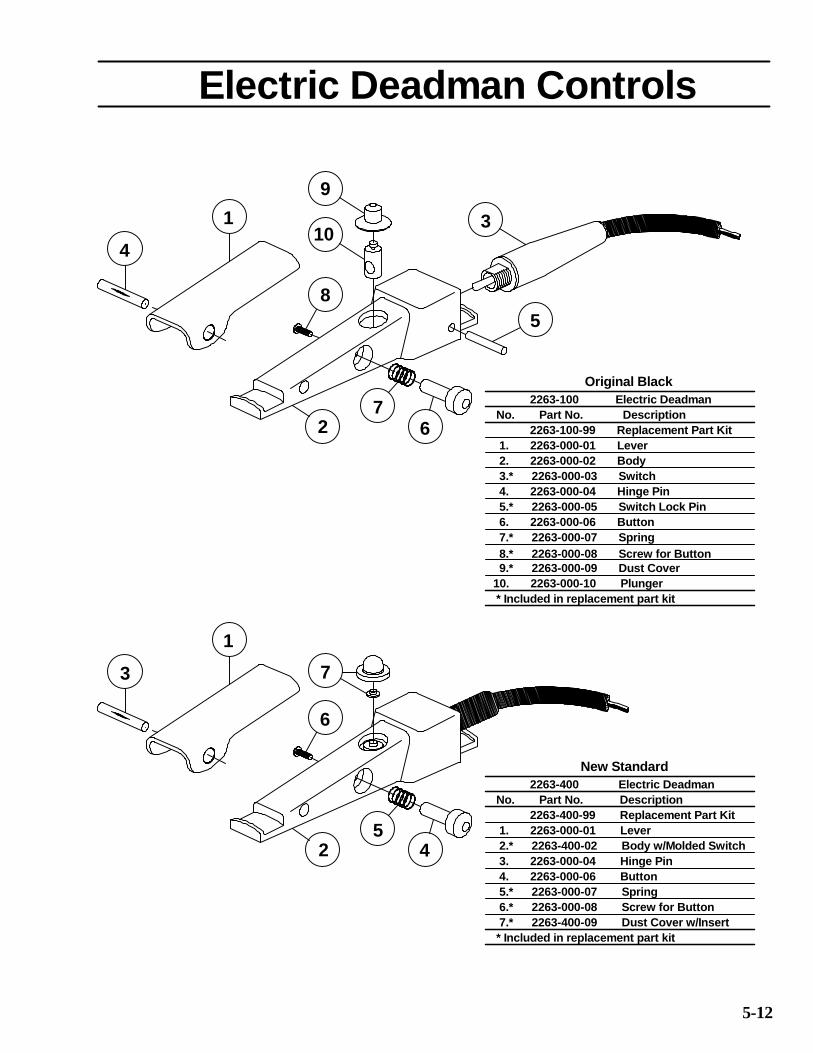
10. 2263-000-10 Plunger
2263-400 Electric Deadman
2.* 2263-400-02 Body w/Molded Switch
2263-400-99 Replacement Part Kit
* Included in replacement part kit
No. Part No. Description
* Included in replacement part kit
7.* 2263-400-09 Dust Cover w/Insert
1. 2263-000-01 Lever
3. 2263-000-04 Hinge Pin
4. 2263-000-06 Button
5.* 2263-000-07 Spring
6.* 2263-000-08 Screw for Button
2 4
1
3
6
7
5
5-12
New Standard
7.* 2263-000-07 Spring
6. 2263-000-06 Button
9.* 2263-000-09 Dust Cover
8.* 2263-000-08 Screw for Button
Electric Deadman Controls
3.* 2263-000-03 Switch
2. 2263-000-02 Body
4. 2263-000-04 Hinge Pin
2263-100 Electric Deadman
No. Part No. Description
2263-100-99 Replacement Part Kit
1. 2263-000-01 Lever
5.* 2263-000-05 Switch Lock Pin
67
2
1
410
9
8
3
5
Original Black

22
7
9
20
8
17
14
1
3
6
5
1319
11
10
NOTE: With spring closed valve air flow is in opposite direction from arrow on valve body.
18
21
5-13
AIR
4
FLOW
25
*
*
*
*
*
*
*
*
*
24. 2123-106-24 Spring
15. 2123-006-15 Diaphragm Plate
17. 2123-006-17 Lock Nut
22. Not Needed
24. 2123-109-24 Spring
15. 2123-009-15 Diaphragm Plate
(Normally Closed) Automatic Air Valve
20. 2123-009-20 Gasket
5. 2123-009-05 O-ring
2123-109 2" Valve
23
15
*
* Included In Replacement Part Kit
2. 2123-009-02 Diaphragm
1. 2123-009-01 Gasket
17. 2123-009-17 Lock Nut
*
21. 2123-006-21 Disc
18. 2123-006-18 Body, 1"
12
* Included In Replacement Part Kit
22. 2123-106-22 Gasket
19. 2123-006-19 Shaft
15 242
*
4. 2123-009-04 Retainer Bushing
21. 2123-009-21 Disc
18. 2123-009-18 Body, 2"
19. 2123-009-19 Shaft
No. Part No. Description
*
*
*
*
*
6. 2123-009-06 Disk Retainer
13. 2123-009-13 Lock Nut
12. 2123-109-12 Cap
10. "Deleted" Lock Washer, Internal
11. 2123-009-11 Lock Nut
14. 2123-009-14 Cap Screw
9. 2123-009-09 Disc Plate
8. 2123-009-08 Seat
7. 2123-009-07 O-ring
25. 2014-300 Vent, 1/8" (not included)
23. 2123-109-23 Spring Retainer21. 2123-007-21 Disc
19. 2123-007-19 Shaft
20. 2123-007-20 Gasket
24. 2123-107-24 Spring
No. Part No. Description
2. 2123-006-02 Diaphragm
1. 2123-006-01 Gasket
2123-106 1" Valve
20. 2123-006-20 Gasket
*
*
*
*
3. 2123-007-03 O-ring4. 2123-006-04 Retainer Bushing
3. 2123-009-03 O-ring
2123-009-99 Replacement Part Kit
23. 2123-106-23 Spring Retainer
17. 2123-007-17 Lock Nut
15. 2123-007-15 Diaphragm Plate
18. 2123-007-18 Body, 1 1/4"
*
2. 2123-007-02 Diaphragm
2123-107 1 1/4" Valve
No. Part No. Description
2123-007-99 Replacement Part Kit
22. 2123-107-22 Gasket
2123-108 1 1/2" Valve
1. 2123-007-01 Gasket
3. 2123-006-03 O-ring*
*
*
5. 2123-006-05 O-ring
6. 2123-006-06 Disk Retainer
13. 2123-006-13 Lock Nut
12. 2123-106-12 Cap
10. "Deleted" Lock Washer, Internal
11. 2123-006-11 Lock Nut
14. 2123-006-14 Cap Screw
9. 2123-006-09 Disc Plate
8. 2123-006-08 Seat
7. 2123-006-07 O-ring
25. 2014-300 Vent, 1/8" (not included)
2123-006-99 Replacement Part Kit
*
*
2123-008-18 Body, 1 1/2"
13. 2123-007-13 Lock Nut
6. 2123-007-06 Disk Retainer
5. 2123-007-05 O-ring
4. 2123-007-04 Retainer Bushing
7. 2123-007-07 O-ring
8. 2123-007-08 Seat
9. 2123-007-09 Disc Plate
14. 2123-007-14 Cap Screw
11. 2123-007-11 Lock Nut
10. "Deleted" Lock Washer, Internal
12. 2123-107-12 Cap
25. 2014-300 Vent, 1/8" (not included)
23. 2123-107-23 Spring Retainer
* Included In Replacement Part Kit
18
8
13
12
15
16
10
11
9
13
17
14
5-14
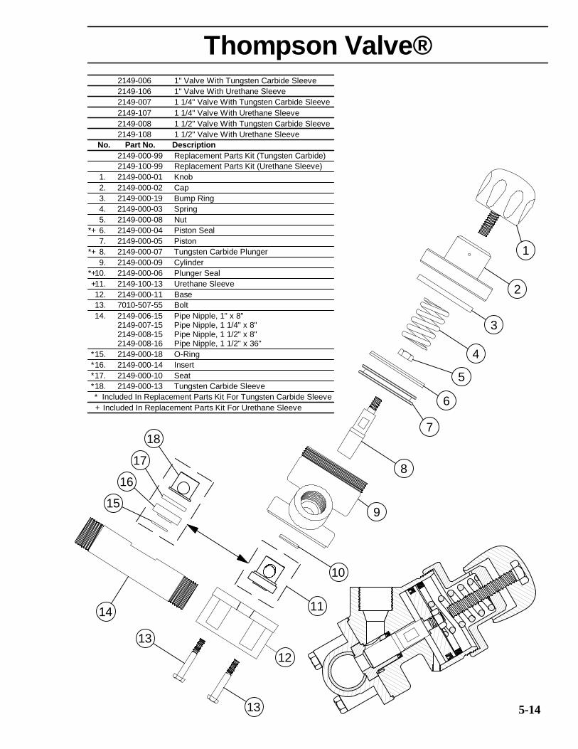
Thompson Valve®
No. Part No. Description
2149-100-99 Replacement Parts Kit (Urethane Sleeve)
2149-000-99 Replacement Parts Kit (Tungsten Carbide)
Included In Replacement Parts Kit For Urethane Sleeve
* Included In Replacement Parts Kit For Tungsten Carbide Sleeve
14. 2149-006-15 Pipe Nipple, 1" x 8"
2149-008-15 Pipe Nipple, 1 1/2" x 8"2149-008-16 Pipe Nipple, 1 1/2" x 36"
15. 2149-000-18 O-Ring
16. 2149-000-14 Insert
2149-007-15 Pipe Nipple, 1 1/4" x 8"
18. 2149-000-13 Tungsten Carbide Sleeve
17. 2149-000-10 Seat
2. 2149-000-02 Cap
1. 2149-000-01 Knob
3. 2149-000-19 Bump Ring
4. 2149-000-03 Spring
7. 2149-000-05 Piston
6. 2149-000-04 Piston Seal
5. 2149-000-08 Nut
9. 2149-000-09 Cylinder
8. 2149-000-07 Tungsten Carbide Plunger
12. 2149-000-11 Base
10. 2149-000-06 Plunger Seal
11. 2149-100-13 Urethane Sleeve
13. 7010-507-55 Bolt
*+
*
*
*
*
+
*+
*+
+
2149-006 1" Valve With Tungsten Carbide Sleeve
2149-007 1 1/4" Valve With Tungsten Carbide Sleeve
2149-106 1" Valve With Urethane Sleeve
2149-108 1 1/2" Valve With Urethane Sleeve
2149-107 1 1/4" Valve With Urethane Sleeve
2149-008 1 1/2" Valve With Tungsten Carbide Sleeve
7
5
3
2
4
1
6

16
28. 3006-106 Street Elbow 90°, 1" Galv.
27. 8403-000-54 Cleanout Ball Valve Adder
26. 2152-000-10 Seat
* Included In Replacement Part Kit For Tungsten Carbide Sleeve
29. 3029-106-09 Nipple TBE, 1" x 2" Lg. Galv.
Included In Replacement Part Kit For Urethane Sleeve
30. 2401-506 Ball Valve, 1" Full Port
27
*
+
30
5
20
21
22
25
28
29
26
24
27
23
OR
17
19
18A
ir S
ignal P
ort
5-14a
14
13
15
Thompson Valve® II
21. 2152-000-19 Base, 1" NPT
20. 2152-100-13 Urethane Sleeve
19. 2152-000-14 Body
25. 2152-000-13 Tungsten Carbide Sleeve
2152-000-11 Base, 1 1/2" NPT
23. 3014-106 Plug
24. 2152-000-21 O-Ring
22. 7010-507-95 Hex Bolt, 3/8" UNC x 4 3/4" Lg.
2152-000-15 Base, 1 1/4" NPT
2152-006 1" Valve With Tungsten Carbide Sleeve
2152-106 1" Valve With Urethane Sleeve
7. 2152-000-02 Cap Plate
9. 2149-000-19 Bump Ring
2152-000-99 Replacement Parts Kit (Tungsten Carbide)
1. 2152-000-01 Knob
18. 2152-000-06 Plunger Seal (Urethane)
3. 2152-000-12 Spring Retainer
5. 7027-503-02 Washer
4. 2152-000-18 O-Ring
6. 7010-507-07 Hex Bolt, 3/8" UNC x 1-1/4" Lg.
15. 2152-000-07 Tungsten Carbide Plunger
17. 2149-500-06 Plunger Seal (Molythane)
10. 2152-000-25 Vibration Disc
16. 2152-000-09 Cylinder
12. 2149-000-08 Nut
11. 2152-000-03 Spring
8. 2152-000-16 Cap Gasket
14. 2152-000-05 Piston
13. 2149-000-04 Piston Seal
2. 2152-000-17 Breather Vent
No. Part No. Description
2152-100-99 Replacement Parts Kit (Urethane)
2152-108 1 1/2" Valve With Urethane Sleeve
2152-007 1 1/4" Valve With Tungsten Carbide Sleeve
2152-107 1 1/4" Valve With Urethane Sleeve
2152-008 1 1/2" Valve With Tungsten Carbide Sleeve
*+*+
++
*
*
*+*+
*+*+
*+*+
*+*+
*+*+
53
11
10
9
12
8
6
7
4
2
1
5-15
6-1
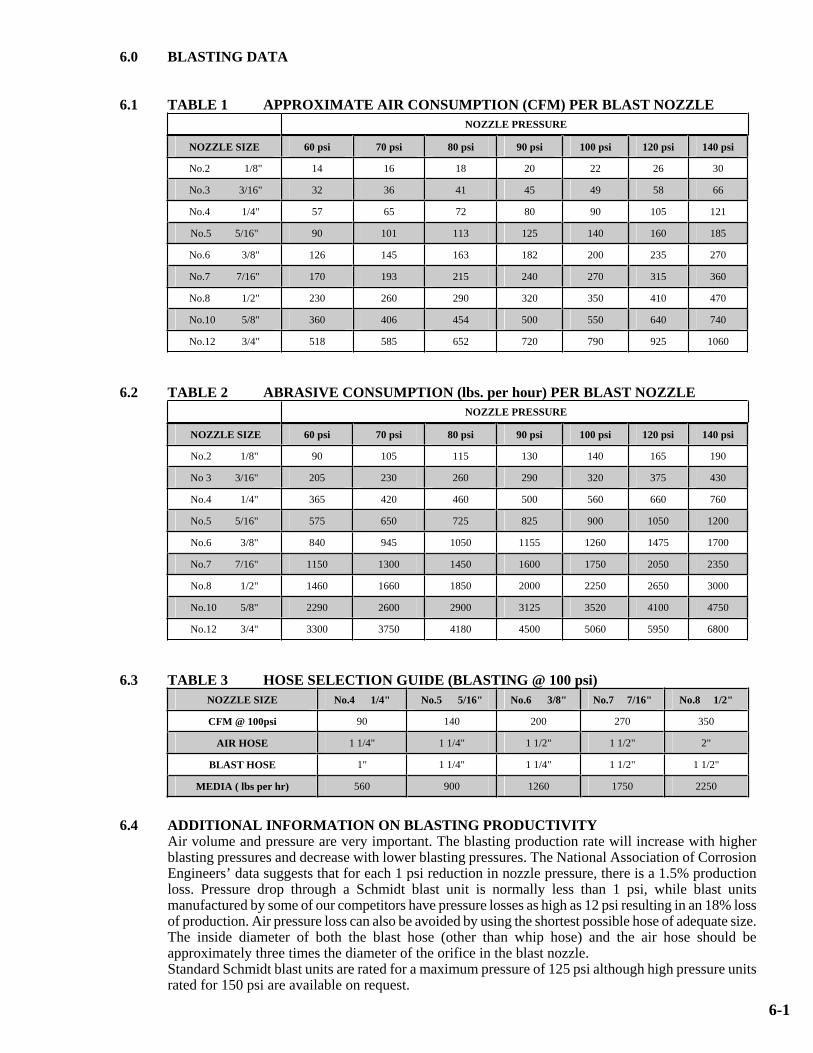
6.0 BLASTING DATA
6.1 TABLE 1 APPROXIMATE AIR CONSUMPTION (CFM) PER BLAST NOZZLE
NOZZLE PRESSURE
NOZZLE SIZE 60 psi 70 psi 80 psi 90 psi 100 psi 120 psi 140 psi
No.2 1/8" 14 16 18 20 22 26 30
No.3 3/16" 32 36 41 45 49 58 66
No.4 1/4" 57 65 72 80 90 105 121
No.5 5/16" 90 101 113 125 140 160 185
No.6 3/8" 126 145 163 182 200 235 270
No.7 7/16" 170 193 215 240 270 315 360
No.8 1/2" 230 260 290 320 350 410 470
No.10 5/8" 360 406 454 500 550 640 740
No.12 3/4" 518 585 652 720 790 925 1060
6.2 TABLE 2 ABRASIVE CONSUMPTION (lbs. per hour) PER BLAST NOZZLE
NOZZLE PRESSURE
NOZZLE SIZE 60 psi 70 psi 80 psi 90 psi 100 psi 120 psi 140 psi
No.2 1/8" 90 105 115 130 140 165 190
No 3 3/16" 205 230 260 290 320 375 430
No.4 1/4" 365 420 460 500 560 660 760
No.5 5/16" 575 650 725 825 900 1050 1200
No.6 3/8" 840 945 1050 1155 1260 1475 1700
No.7 7/16" 1150 1300 1450 1600 1750 2050 2350
No.8 1/2" 1460 1660 1850 2000 2250 2650 3000
No.10 5/8" 2290 2600 2900 3125 3520 4100 4750
No.12 3/4" 3300 3750 4180 4500 5060 5950 6800
6.3 TABLE 3 HOSE SELECTION GUIDE (BLASTING @ 100 psi)
NOZZLE SIZE No.4 1/4" No.5 5/16" No.6 3/8" No.7 7/16" No.8 1/2"
CFM @ 100psi 90 140 200 270 350
AIR HOSE 1 1/4" 1 1/4" 1 1/2" 1 1/2" 2"
BLAST HOSE 1" 1 1/4" 1 1/4" 1 1/2" 1 1/2"
MEDIA ( lbs per hr) 560 900 1260 1750 2250
6.4 ADDITIONAL INFORMATION ON BLASTING PRODUCTIVITYAir volume and pressure are very important. The blasting production rate will increase with higher blasting pressures and decrease with lower blasting pressures. The National Association of Corrosion Engineers’ data suggests that for each 1 psi reduction in nozzle pressure, there is a 1.5% production loss. Pressure drop through a Schmidt blast unit is normally less than 1 psi, while blast units manufactured by some of our competitors have pressure losses as high as 12 psi resulting in an 18% loss of production. Air pressure loss can also be avoided by using the shortest possible hose of adequate size. The inside diameter of both the blast hose (other than whip hose) and the air hose should be approximately three times the diameter of the orifice in the blast nozzle. Standard Schmidt blast units are rated for a maximum pressure of 125 psi although high pressure units rated for 150 psi are available on request.

7-1
7.0 TROUBLE SHOOTINGThe folowing section covers procedures for solving problems that may arise during operation of theblasting quipment. Note that the below mentioned data may not all apply to your particular unit. Thesignificance of the data is dependant on the control type and accesories furnished on the unit
7.1 Air Blast But No Abrasive
7.1.1 The pot is empty7.1.2 The abrasive in the pot is wet. Try closing the choke valve until some abrasive is pumped out.
Operating the unit in the “choked” condition will allow the use of media that is too damp to flow properly, but it greatly accelerates wear in the metering valve. Continuous running in the choked condition also reduces productivity and therefore should be avoided if possible.
7.1.3 Foreign matter is plugging the abrasive metering valve. Try closing the choke valve and opening the abrasive metering valve momentarily to see if that will blow the obstruction out. If that does not work, then it will be necessary to de-pressurize the pot and remove the obstruction by hand.
7.2 Reduced Pressure At The Nozzle (with or without abrasive flow)
7.2.1 Insufficient air compressor output (see air requirements is section 6.0).7.2.2 Air hose too small.7.2.3 Abrasive metering valve adjustment open too far.7.2.4 Pop-up not seating properly.7.2.5 Choke valve partially closed.7.2.6 Trash may partially plugging the nozzle orifice.
7.3 Unit Is Slow To Turn On Or Will Not Turn On
7.3.1 Air hose is too small. The air hose diameter should be at least three (3) times the nozzle diameter. (Symptom: Air will blow out of the blowdown but the pot does not pressurize.)
7.3.2 Insufficient air compressor output. (Symptom: Air will blow out of the blowdown but the pot does not pressurize.)
7.3.3 Check quick connect couplings on control hoses to be sure they are engaged properly.7.3.4 Control hoses are leaking. (Symptom: The pot will turn on slowly or does not turn on at all.)7.3.5 Control hoses are plugged. If the black hose is disconnected from the cylinder of the combo valve,
there should be air pressure whenever the deadman is depressed.7.3.6 Worn piston seal in the combo valve. (Symptom: Air will blow out of the brass breather vent on
the combo valve.)7.3.7 Deadman is plugged. (Symptom: Only a weak air signal, or none at all will come from the
deadman when the black hose is disconnected.)7.3.8 Defective cartridge in the deadman valve. (Symptom: Air will blow out of the deadman whenever
the lever is depressed.)7.3.9 On normally closed systems only: Defective diaphragm in the automatic air valve.7.3.10 On normally closed systems only: Defective diaphragm in the blowdown valve.
7.4 Unit Is Slow To Turn Off Or Will Not Turn Off
7.4.1 Twinline hoses are crossed. The left part of the deadman (when viewed from the hose connection end) should be connected to the combo valve using the black hose.
7.4.2 The lower rod guide seal is defective. If you disconnect the black hose from the 1/8" port on the combo valve, air should not blow out of the combo valve.
7.4.3 The lower rod guide o-ring is damaged or missing.7.4.4 The lower rod guide is installed upside down. (Symptom: The pot turns on as soon as the air
supply is turned on.)7.4.5 The valve plug in the combo valve is defective and will not seal.7.4.6 A bleeder type deadman valve has been installed.
7.5 Unit Turns On Accidentally
7.5.1 The lever on the deadman valve is worn out.7.5.2 The safety button on the deadman valve is missing.7.5.3 A bleeder type valve has been installed. A bleeder type deadman valve is unsafe because a piece
of dirt from the air hose can plug the hole in the deadman and cause the blast unit to turn on.