Saturday, March 19, 2016 Newport County, Rhode Island, … MCA FCLC LNGF Gas Measuring...03 LNG...
28
Copyright © 2016 United States Maritime Resource Center, Inc. All Rights Reserved. 1 Flammable Cryogenic Liquid Carriers Thank You to the Seminar Sponsor Seminar Provider and Host Saturday, March 19, 2016 Newport County, Rhode Island, USA
Transcript of Saturday, March 19, 2016 Newport County, Rhode Island, … MCA FCLC LNGF Gas Measuring...03 LNG...
Copyright © 2015 United States Maritime Resource Center, Inc. All Rights Reserved. 1Copyright © 2016 United States Maritime Resource Center, Inc. All Rights Reserved. 1
Flammable Cryogenic Liquid Carriers
Thank You to the Seminar Sponsor
Seminar Provider and Host
Saturday, March 19, 2016
Newport County, Rhode Island, USA
Copyright © 2015 United States Maritime Resource Center, Inc. All Rights Reserved. 2Copyright © 2016 United States Maritime Resource Center, Inc. All Rights Reserved. 2
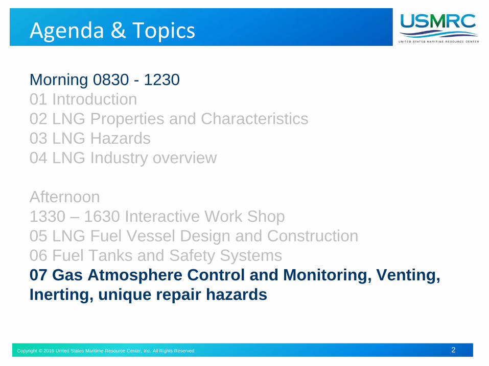
Agenda & Topics
Morning 0830 - 1230
01 Introduction
02 LNG Properties and Characteristics
03 LNG Hazards
04 LNG Industry overview
Afternoon
1330 – 1630 Interactive Work Shop
05 LNG Fuel Vessel Design and Construction
06 Fuel Tanks and Safety Systems
07 Gas Atmosphere Control and Monitoring, Venting,
Inerting, unique repair hazards

Copyright © 2016 United States Maritime Resource Center, Inc. All Rights Reserved. 3Copyright © 2016 United States Maritime Resource Center, Inc. All Rights Reserved. 3
07 LNGF Gas Atmosphere Control & Monitoring
Unique HazardsEmptyingInertingPurging DryingGas Freeing Venting
Copyright © 2016 United States Maritime Resource Center, Inc. All Rights Reserved. 4
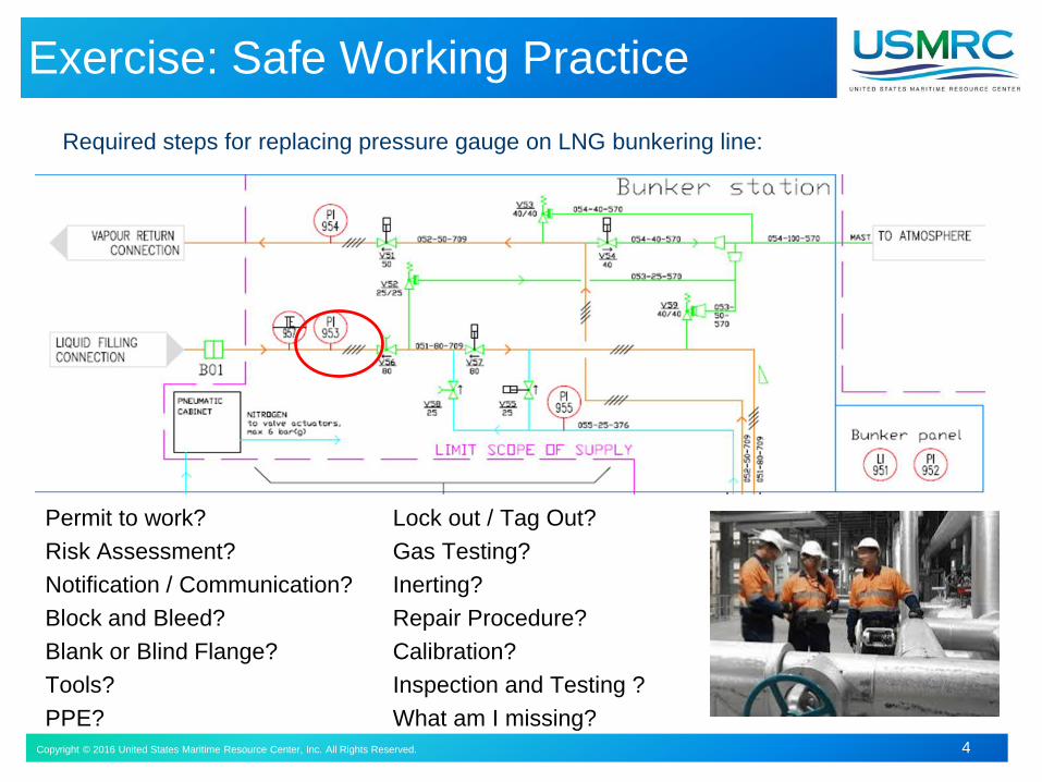
Exercise: Safe Working Practice
Required steps for replacing pressure gauge on LNG bunkering line:
Permit to work?
Risk Assessment?
Notification / Communication?
Block and Bleed?
Blank or Blind Flange?
Tools?
PPE?
Lock out / Tag Out?
Gas Testing?
Inerting?
Repair Procedure?
Calibration?
Inspection and Testing ?
What am I missing?
Copyright © 2016 United States Maritime Resource Center, Inc. All Rights Reserved. 5
Emptying
• Requirement to empty, purge and vent independent of gas
consumers
• Must use the vessel piping system
–Tank and piping arranged to minimize pockets of gas or air
remaining
–Gas sampling points provided at the fuel tank
• Instructions must be available on board
• Always inert tank prior to venting
• Inert gas may be provided from an external source
Copyright © 2016 United States Maritime Resource Center, Inc. All Rights Reserved. 6
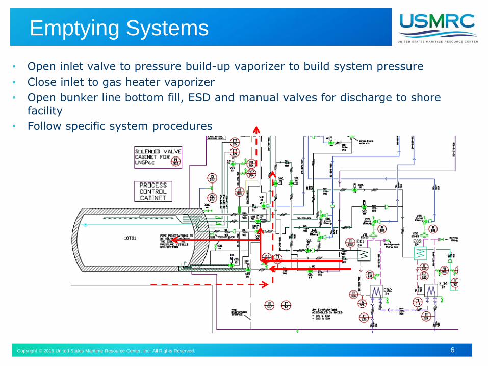
Emptying Systems
• Open inlet valve to pressure build-up vaporizer to build system pressure
• Close inlet to gas heater vaporizer
• Open bunker line bottom fill, ESD and manual valves for discharge to shore facility
• Follow specific system procedures
Copyright © 2016 United States Maritime Resource Center, Inc. All Rights Reserved. 7
Emptying, Inerting, Drying and Monitoring
Should be possible to empty, purge gas and vent bunker tanks with
the gas piping system
Should not be dependent on the gas machinery system
Procedures for emptying, purging and venting should be developed
Fuel gas storage and transfer systems must be kept dry to prevent
formation of ice in pipes , tanks and gas handling equipment
N2 supply should be equipped with dryer and dewpoint monitoring to
insure dry inert gas supply
Water vapor in piping systems can condense when cold gas is
introduced
Generally dew points below -40 C are standard for LNG piping and
storage tank drying
Copyright © 2016 United States Maritime Resource Center, Inc. All Rights Reserved. 8
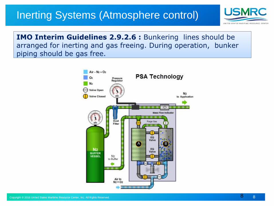
Inerting Systems (Atmosphere control)
8
IMO Interim Guidelines 2.9.2.6 : Bunkering lines should be arranged for inerting and gas freeing. During operation, bunker piping should be gas free.
Copyright © 2016 United States Maritime Resource Center, Inc. All Rights Reserved. 9
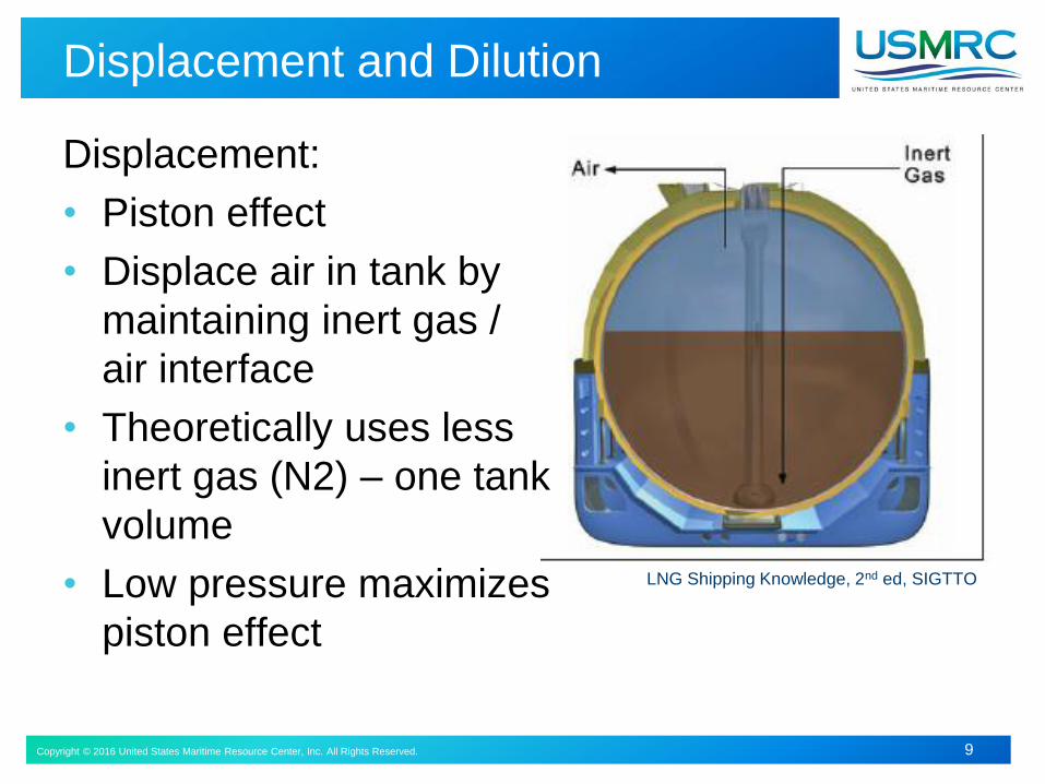
Displacement and Dilution
LNG Shipping Knowledge, 2nd ed, SIGTTO
Displacement:
• Piston effect
• Displace air in tank by
maintaining inert gas /
air interface
• Theoretically uses less
inert gas (N2) – one tank
volume
• Low pressure maximizes
piston effect

Copyright © 2016 United States Maritime Resource Center, Inc. All Rights Reserved. 10
Drying and Inerting
Inerting / Drying by Dilution:
Inert gas pressurized into tank
from N2 Supply inlet piping
The N2 will displace tank
atmosphere through vapor
return line to engine, shore tank
or atmosphere
N2 should be completely dry with
a dew point less than -40° C and
moisture content set point control
Monitor gas discharge methane
content to minimize methane
emission to atmosphere
Ideally burn gas in engine or
other consumer until all methane
consumed
Copyright © 2016 United States Maritime Resource Center, Inc. All Rights Reserved. 11
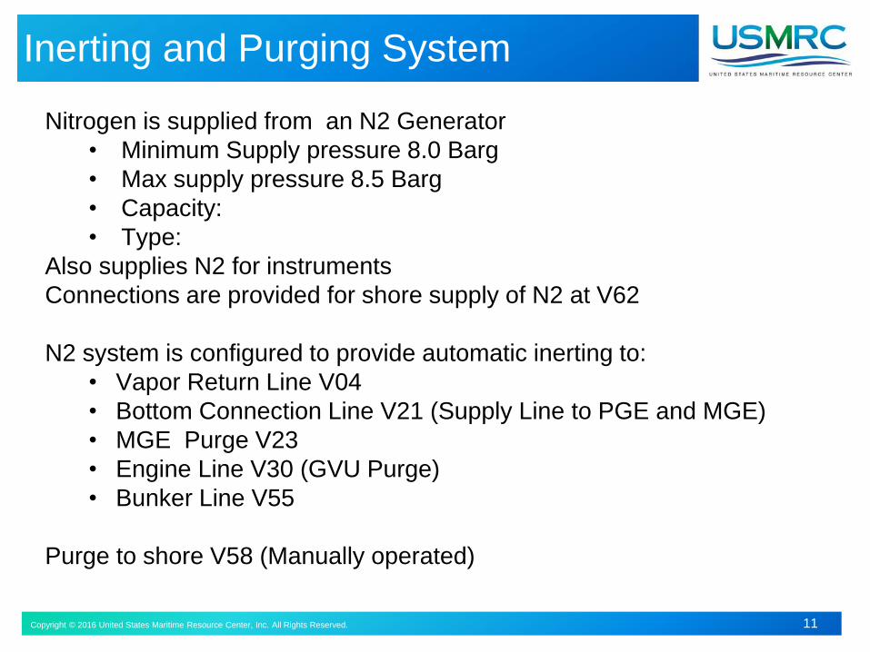
Inerting and Purging System
Nitrogen is supplied from an N2 Generator
• Minimum Supply pressure 8.0 Barg
• Max supply pressure 8.5 Barg
• Capacity:
• Type:
Also supplies N2 for instruments
Connections are provided for shore supply of N2 at V62
N2 system is configured to provide automatic inerting to:
• Vapor Return Line V04
• Bottom Connection Line V21 (Supply Line to PGE and MGE)
• MGE Purge V23
• Engine Line V30 (GVU Purge)
• Bunker Line V55
Purge to shore V58 (Manually operated)
Copyright © 2016 United States Maritime Resource Center, Inc. All Rights Reserved. 12
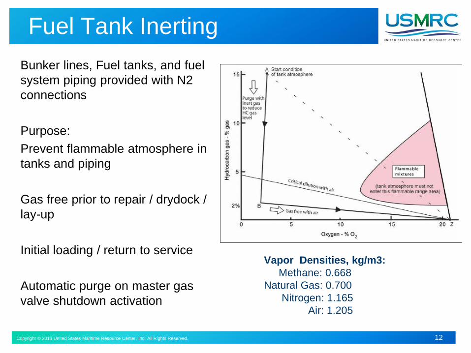
Fuel Tank Inerting
Bunker lines, Fuel tanks, and fuel
system piping provided with N2
connections
Purpose:
Prevent flammable atmosphere in
tanks and piping
Gas free prior to repair / drydock /
lay-up
Initial loading / return to service
Automatic purge on master gas
valve shutdown activation
Vapor Densities, kg/m3:
Methane: 0.668
Natural Gas: 0.700
Nitrogen: 1.165
Air: 1.205
Copyright © 2016 United States Maritime Resource Center, Inc. All Rights Reserved. 13
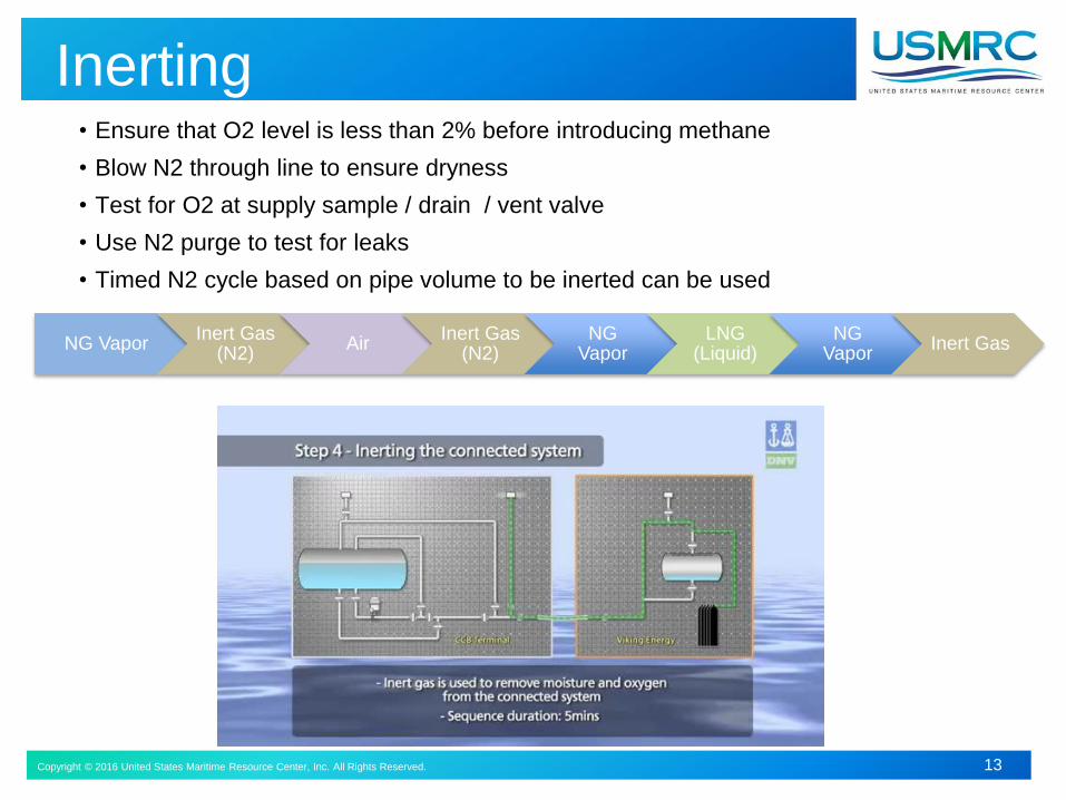
Inerting• Ensure that O2 level is less than 2% before introducing methane
• Blow N2 through line to ensure dryness
• Test for O2 at supply sample / drain / vent valve
• Use N2 purge to test for leaks
• Timed N2 cycle based on pipe volume to be inerted can be used
NG VaporInert Gas
(N2)Air
Inert Gas (N2)
NG Vapor
LNG (Liquid)
NG Vapor
Inert Gas
Copyright © 2016 United States Maritime Resource Center, Inc. All Rights Reserved. 14
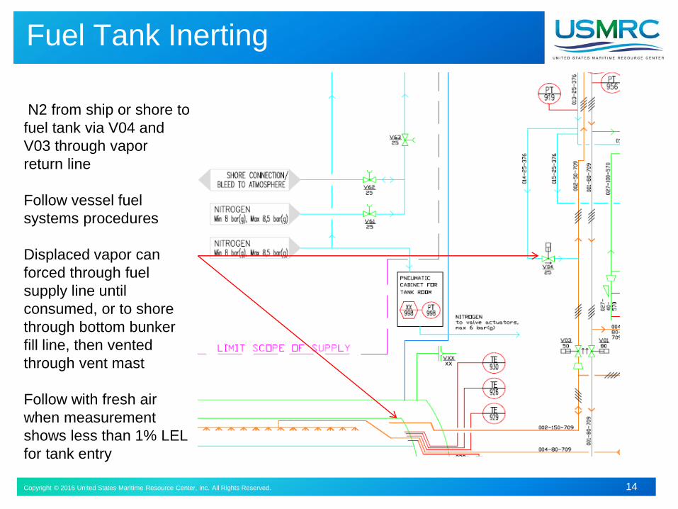
Fuel Tank Inerting
N2 from ship or shore to
fuel tank via V04 and
V03 through vapor
return line
Follow vessel fuel
systems procedures
Displaced vapor can
forced through fuel
supply line until
consumed, or to shore
through bottom bunker
fill line, then vented
through vent mast
Follow with fresh air
when measurement
shows less than 1% LEL
for tank entry
Copyright © 2016 United States Maritime Resource Center, Inc. All Rights Reserved. 15
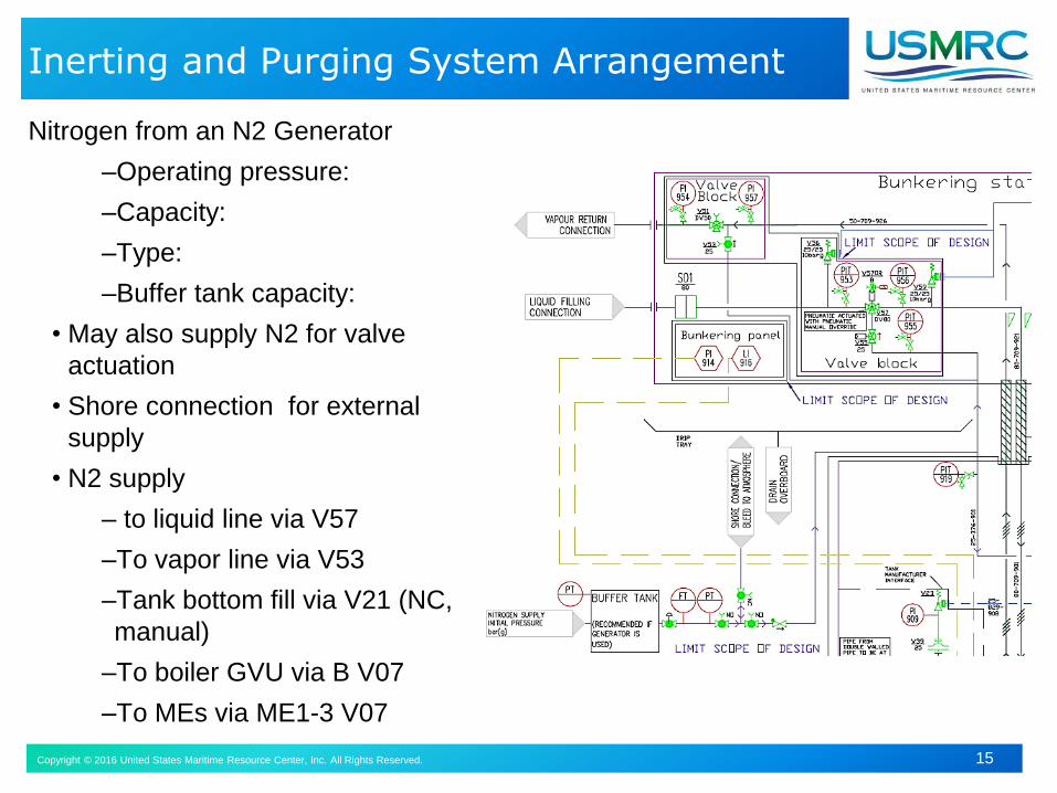
Inerting and Purging System Arrangement
Nitrogen from an N2 Generator
–Operating pressure:
–Capacity:
–Type:
–Buffer tank capacity:
• May also supply N2 for valve
actuation
• Shore connection for external
supply
• N2 supply
– to liquid line via V57
–To vapor line via V53
–Tank bottom fill via V21 (NC,
manual)
–To boiler GVU via B V07
–To MEs via ME1-3 V07
Copyright © 2016 United States Maritime Resource Center, Inc. All Rights Reserved. 16
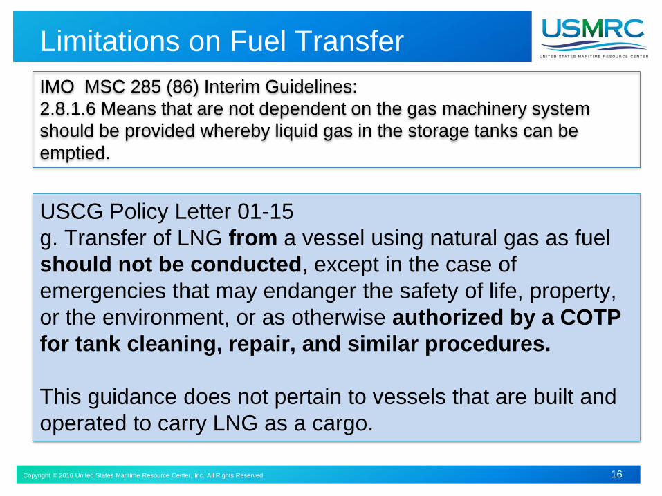
Limitations on Fuel Transfer
IMO MSC 285 (86) Interim Guidelines:
2.8.1.6 Means that are not dependent on the gas machinery system
should be provided whereby liquid gas in the storage tanks can be
emptied.
USCG Policy Letter 01-15
g. Transfer of LNG from a vessel using natural gas as fuel
should not be conducted, except in the case of
emergencies that may endanger the safety of life, property,
or the environment, or as otherwise authorized by a COTP
for tank cleaning, repair, and similar procedures.
This guidance does not pertain to vessels that are built and
operated to carry LNG as a cargo.
Copyright © 2016 United States Maritime Resource Center, Inc. All Rights Reserved. 17
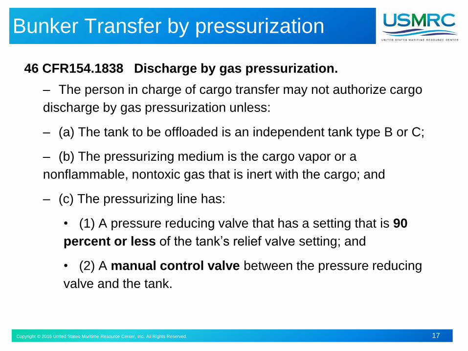
Bunker Transfer by pressurization
46 CFR154.1838 Discharge by gas pressurization.
– The person in charge of cargo transfer may not authorize cargo
discharge by gas pressurization unless:
– (a) The tank to be offloaded is an independent tank type B or C;
– (b) The pressurizing medium is the cargo vapor or a
nonflammable, nontoxic gas that is inert with the cargo; and
– (c) The pressurizing line has:
• (1) A pressure reducing valve that has a setting that is 90
percent or less of the tank’s relief valve setting; and
• (2) A manual control valve between the pressure reducing
valve and the tank.
Copyright © 2016 United States Maritime Resource Center, Inc. All Rights Reserved. 18
Bunker Transfer by Gas Pressurization
IGC 5.8.2
The procedure for transfer of cargo by gas pressurization should preclude lifting of the relief valves during such transfer.
Gas pressurization may be accepted as a means of transfer of cargo as long as the design factor of safety is not reduced during the cargo transfer operation.
Copyright © 2016 United States Maritime Resource Center, Inc. All Rights Reserved. 19Copyright © 2015 United States Maritime Resource Center, Inc. All Rights Reserved. 19
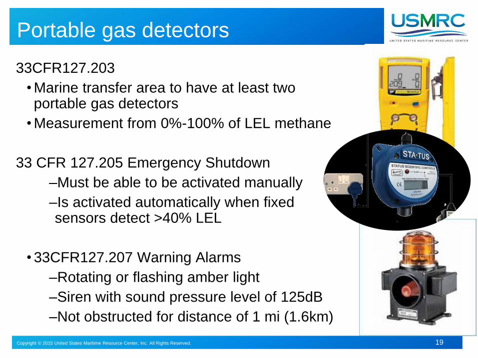
33CFR127.203
• Marine transfer area to have at least two portable gas detectors
• Measurement from 0%-100% of LEL methane
33 CFR 127.205 Emergency Shutdown
–Must be able to be activated manually
–Is activated automatically when fixed sensors detect >40% LEL
• 33CFR127.207 Warning Alarms
–Rotating or flashing amber light
–Siren with sound pressure level of 125dB
–Not obstructed for distance of 1 mi (1.6km)
Portable gas detectors
Copyright © 2016 United States Maritime Resource Center, Inc. All Rights Reserved. 20
Monitoring, Control and Safety Systems
Monitored Parameters:
Pressure when bunkering / transferring fuel
Tank rooms for liquid level and temperature, with alarms and automatic main tank valve closure
Monitor / Protection against fuel tank overfilling
Engine operation and mode indicators,
Gas extraction from lube and cooling systems
Gas detection in TCS, ducted piping, ESD protected machinery spaces, enclosed spaces containing gas piping or equipment
Fire Detection, tank room and machinery space
Operation and status of Ventilation system(s)
Copyright © 2016 United States Maritime Resource Center, Inc. All Rights Reserved. 21
Monitoring & Control Functional Requirements
Interim Guidelines and IGF Code require Automatic Control, Monitoring, Alarm and Safety Functions to be provided for each component of gas fuel systems
Safety, reliability and dependability equivalent to conventional oil fueled vessel
Gas fueled vessel operations should always be within design limits and presetparameters for safe, reliable storage tank filling, fuel gas supply system and vessel operation
Ventilation, Detection and Safety shutdowns are arranged to deal with situations that occur too quickly for manual intervention
Design Philosophy: Safety shutdowns should not lead to an unacceptable loss of power or disabling other equipment
Automation, instrumentation, monitoring and control systems are to be provided to enable safe carriage, conditioning and use of natural gas, and to prevent venting.
Vessel and systems are arranged with sufficient redundancy to provide continuity of electrical and propulsion power
Single failure shall not lead to unsafe or unreliable situation
Copyright © 2016 United States Maritime Resource Center, Inc. All Rights Reserved. 22
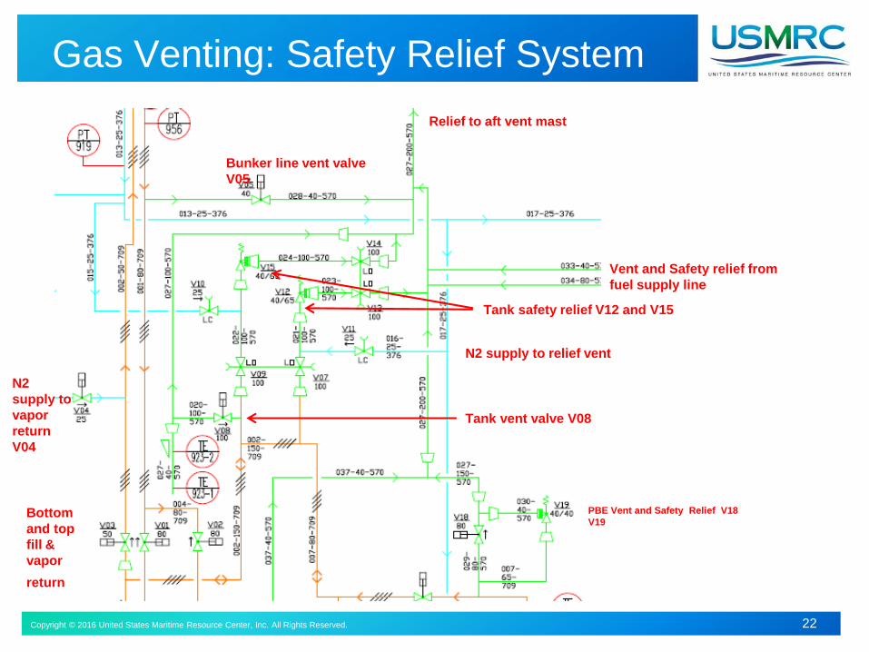
Gas Venting: Safety Relief System
Relief to aft vent mast
Bunker line vent valve
V05
N2 supply to relief vent
Tank safety relief V12 and V15
Vent and Safety relief from
fuel supply line
Tank vent valve V08
N2
supply to
vapor
return
V04
Bottom
and top
fill &
vapor
return
PBE Vent and Safety Relief V18
V19
Copyright © 2016 United States Maritime Resource Center, Inc. All Rights Reserved. 23
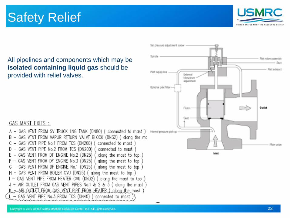
Safety Relief
All pipelines and components which may be
isolated containing liquid gas should be
provided with relief valves.
Copyright © 2015 United States Maritime Resource Center, Inc. All Rights Reserved. 24Copyright © 2016 United States Maritime Resource Center, Inc. All Rights Reserved. 24
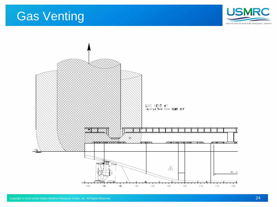
Gas Venting
Copyright © 2016 United States Maritime Resource Center, Inc. All Rights Reserved. 25
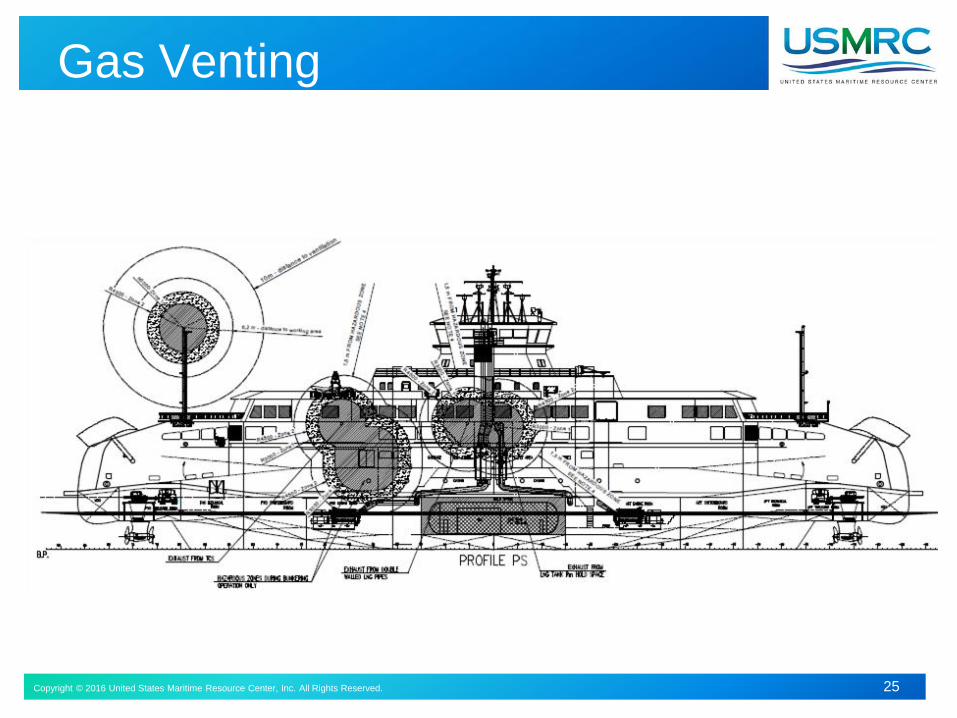
Gas Venting
Copyright © 2015 United States Maritime Resource Center, Inc. All Rights Reserved. 26Copyright © 2016 United States Maritime Resource Center, Inc. All Rights Reserved. 26
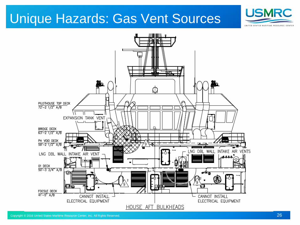
Unique Hazards: Gas Vent Sources
Copyright © 2015 United States Maritime Resource Center, Inc. All Rights Reserved. 27Copyright © 2016 United States Maritime Resource Center, Inc. All Rights Reserved. 27
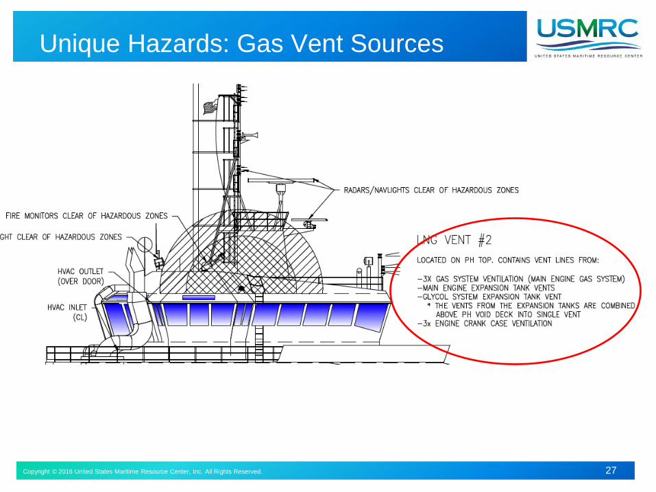
Unique Hazards: Gas Vent Sources
Copyright © 2015 United States Maritime Resource Center, Inc. All Rights Reserved. 28Copyright © 2016 United States Maritime Resource Center, Inc. All Rights Reserved. 28
End of Section
Questions?