Satellite Receiver Installation Manual -...
30
190-00836-00 August, 2010 Revision F GSR 56 Satellite Receiver Installation Manual
-
Upload
nguyendung -
Category
Documents
-
view
254 -
download
2
Transcript of Satellite Receiver Installation Manual -...
190-00836-00 August, 2010 Revision F
GSR 56 Satellite Receiver Installation Manual
Page A GSR 56 Installation Manual Revision F 190-00836-00
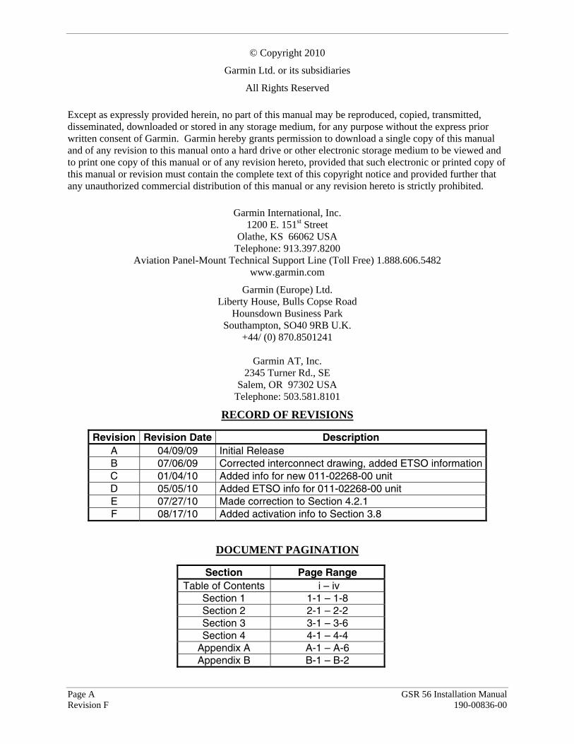
© Copyright 2010
Garmin Ltd. or its subsidiaries
All Rights Reserved
Except as expressly provided herein, no part of this manual may be reproduced, copied, transmitted, disseminated, downloaded or stored in any storage medium, for any purpose without the express prior written consent of Garmin. Garmin hereby grants permission to download a single copy of this manual and of any revision to this manual onto a hard drive or other electronic storage medium to be viewed and to print one copy of this manual or of any revision hereto, provided that such electronic or printed copy of this manual or revision must contain the complete text of this copyright notice and provided further that any unauthorized commercial distribution of this manual or any revision hereto is strictly prohibited.
Garmin International, Inc. 1200 E. 151st Street
Olathe, KS 66062 USA Telephone: 913.397.8200
Aviation Panel-Mount Technical Support Line (Toll Free) 1.888.606.5482 www.garmin.com
Garmin (Europe) Ltd. Liberty House, Bulls Copse Road
Hounsdown Business Park Southampton, SO40 9RB U.K.
+44/ (0) 870.8501241
Garmin AT, Inc. 2345 Turner Rd., SE
Salem, OR 97302 USA Telephone: 503.581.8101
RECORD OF REVISIONS
Revision Revision Date Description A 04/09/09 Initial Release B 07/06/09 Corrected interconnect drawing, added ETSO informationC 01/04/10 Added info for new 011-02268-00 unit D 05/05/10 Added ETSO info for 011-02268-00 unit E 07/27/10 Made correction to Section 4.2.1 F 08/17/10 Added activation info to Section 3.8
DOCUMENT PAGINATION
Section Page Range Table of Contents i – iv
Section 1 1-1 – 1-8 Section 2 2-1 – 2-2 Section 3 3-1 – 3-6 Section 4 4-1 – 4-4
Appendix A A-1 – A-6 Appendix B B-1 – B-2

GSR 56 Installation Manual Page i 190-00836-00 Revision F
INFORMATION SUBJECT TO EXPORT CONTROL LAWS
This document may contain information which is subject to the Export Administration Regulations ("EAR") issued by the United States Department of Commerce (15 CFR, Chapter VII, Subchapter C) and which may not be exported, released, or disclosed to foreign nationals inside or outside of the United States without first obtaining an export license. The preceding statement is required to be included on any and all reproductions in whole or in part of this manual.
WARNING
This product, its packaging, and its components contain chemicals known to the State of California to cause cancer, birth defects, or reproductive harm. This Notice is being provided in accordance with California's Proposition 65. If you have any questions or would like additional information, please refer to our web site at www.garmin.com/prop65.
WARNING
Perchlorate Material – special handling may apply, See www.dtsc.ca.gov./hazardouswaste/perchlorate.
CURRENT REVISION DESCRIPTION
Revision Page
Number(s) Section Number
Description of Change
F 3-5 3.8 Added Flight Data Services activation info
Page ii GSR 56 Installation Manual Revision F 190-00836-00
TABLE OF CONTENTS PARAGRAPH PAGE 1. GENERAL DESCRIPTION 1-1 1.1 Introduction ......................................................................................................................................1-1 1.2 Equipment Description.....................................................................................................................1-1 1.3 Interface Summary ...........................................................................................................................1-2 1.4 Technical Specifications ..................................................................................................................1-3 1.5 Approved Antennas..........................................................................................................................1-4 1.6 Certification......................................................................................................................................1-5 1.7 Reference Documentation ................................................................................................................1-7 1.8 Aviation Limited Warranty ..............................................................................................................1-8 2. INSTALLATION 2-1 2.1 Introduction ......................................................................................................................................2-1 2.2 Installation Materials........................................................................................................................2-1 2.3 Equipment Available........................................................................................................................2-1 2.4 Cabling and Wiring ..........................................................................................................................2-1 2.5 Cooling Air ......................................................................................................................................2-2 2.6 Mounting Requirements...................................................................................................................2-2 3. INSTALLATION PROCEDURE 3-1 3.1 Unpacking Unit ................................................................................................................................3-1 3.2 Wiring Harness Installation..............................................................................................................3-1 3.3 Iridium Antenna Installation ............................................................................................................3-2 3.4 Cable Installation .............................................................................................................................3-4 3.5 Backshell Assembly and Installation ...............................................................................................3-5 3.6 Final Installation...............................................................................................................................3-5 3.7 Post Installation Configuration and Checkout .................................................................................3-5 3.8 Activation of Garmin Flight Data Services......................................................................................3-5 3.9 Troubleshooting ...............................................................................................................................3-6 3.10 Continued Airworthiness .................................................................................................................3-6 4. SYSTEM INTERCONNECTS 4-1 4.1 Pin Function List ..............................................................................................................................4-1 4.2 Power Functions...............................................................................................................................4-2 4.3 Serial Data........................................................................................................................................4-4 4.4 Audio Connections...........................................................................................................................4-4 4.5 Active Low Discrete Outputs...........................................................................................................4-4 APPENDIX A OUTLINE AND INSTALLATION DRAWINGS A-1 APPENDIX B INTERCONNECT DRAWING B-1

GSR 56 Installation Manual Page iii 190-00836-00 Revision F
LIST OF ILLUSTRATIONS FIGURE PAGE 1-1 GSR 56 Unit View (in rack).............................................................................................................1-1 1-2 GSR 56 Block Diagram ...................................................................................................................1-2 2-1 GSR 56 Remote Unit Rack ..............................................................................................................2-2 3-1 Antenna Installation Location ..........................................................................................................3-3 3-2 TNC Connector Installation .............................................................................................................3-4 A-1 GSR 56 (011-01706-00) Outline Drawing......................................................................................A-1 A-2 GSR 56 (011-02268-00) Outline Drawing......................................................................................A-3 A-3 GSR 56 011-01706-00 and 011-02268-00 Installation Drawing ....................................................A-5 B-1 GSR 56 Example Interconnect........................................................................................................ B-1
LIST OF TABLES
TABLE PAGE 1-1 Physical Characteristics ...................................................................................................................1-3 1-2 Input Voltage....................................................................................................................................1-3 1-3 Maximum Current Specifications ....................................................................................................1-3 1-4 General Specifications .....................................................................................................................1-4 1-5 Iridium Antenna Minimum Requirements .......................................................................................1-4 1-6 TSO/ETSO Authorizations for 011-01706-00 .................................................................................1-5 1-7 TSO/ETSO Authorizations for 011-02268-00 .................................................................................1-5 1-8 TSO/ETSO Deviations for 011-01706-00........................................................................................1-6 1-9 TSO/ETSO Deviations for 011-02268-00........................................................................................1-6 1-10 Non-TSO Functions .........................................................................................................................1-7 1-11 Referenced Publications...................................................................................................................1-7 2-1 Unit Part Numbers............................................................................................................................2-1 2-2 Accessories.......................................................................................................................................2-1 3-1 Pin Contact Part Numbers ................................................................................................................3-1 3-2 Recommended Crimp Tools ............................................................................................................3-1 3-3 Troubleshooting ...............................................................................................................................3-6
Page iv GSR 56 Installation Manual Revision F 190-00836-00
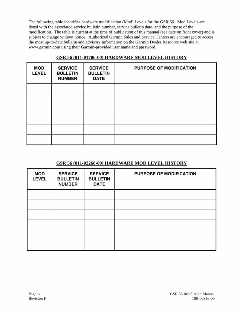
The following table identifies hardware modification (Mod) Levels for the GSR 56. Mod Levels are listed with the associated service bulletin number, service bulletin date, and the purpose of the modification. The table is current at the time of publication of this manual (see date on front cover) and is subject to change without notice. Authorized Garmin Sales and Service Centers are encouraged to access the most up-to-date bulletin and advisory information on the Garmin Dealer Resource web site at www.garmin.com using their Garmin-provided user name and password.
GSR 56 (011-01706-00) HARDWARE MOD LEVEL HISTORY
MOD LEVEL
SERVICE BULLETIN NUMBER
SERVICE BULLETIN
DATE
PURPOSE OF MODIFICATION
GSR 56 (011-02268-00) HARDWARE MOD LEVEL HISTORY
MOD LEVEL
SERVICE BULLETIN NUMBER
SERVICE BULLETIN
DATE
PURPOSE OF MODIFICATION

GSR 56 Installation Manual Page 1-1 190-00836-00 Revision F
1 GENERAL DESCRIPTION
1.1 Introduction
This manual presents mechanical and electrical installation requirements for installing the GSR 56 as part of the Garmin Integrated Flight Deck. The GSR 56 can be integrated into a variety of airframes under an appropriate TC or STC. Each installation may vary. Use only approved (type or supplemental type) data for specific installation instructions in a particular aircraft.
Figure 1-1. GSR 56 Unit View (in rack)
1.2 Equipment Description
The GSR 56 provides airborne low speed data link and voice communication capability to Garmin Integrated Flight Deck installations. The GSR 56 contains a transceiver that operates on the Iridium Satellite network.
Page 1-2 GSR 56 Installation Manual Revision F 190-00836-00
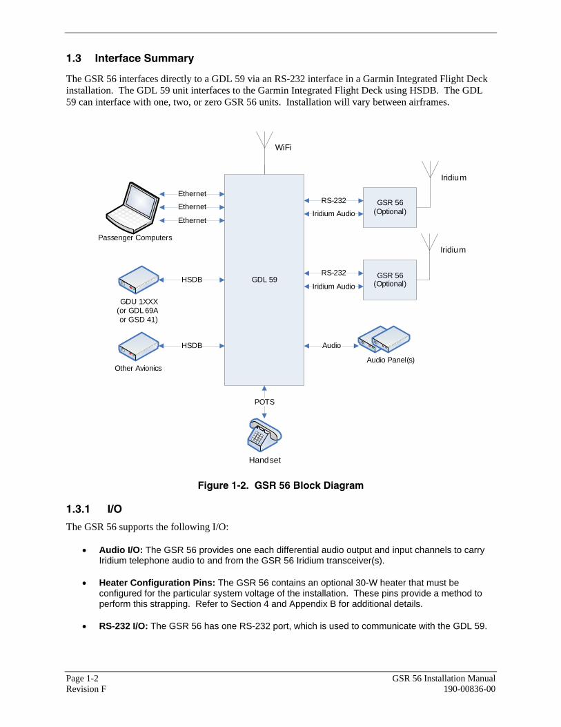
1.3 Interface Summary
The GSR 56 interfaces directly to a GDL 59 via an RS-232 interface in a Garmin Integrated Flight Deck installation. The GDL 59 unit interfaces to the Garmin Integrated Flight Deck using HSDB. The GDL 59 can interface with one, two, or zero GSR 56 units. Installation will vary between airframes.
Passenger Computers
Handset
Other Avionics
Iridium
RS-232Ethernet
Ethernet
Ethernet
WiFi
GDL 59
GSR 56 (Optional)
GSR 56 (Optional)
Iridium
Iridium Audio
GDU 1XXX (or GDL 69A�or GSD 41)
POTS
Audio Panel(s)
RS-232
Iridium Audio
HSDB
HSDB
Audio
Figure 1-2. GSR 56 Block Diagram
1.3.1 I/O
The GSR 56 supports the following I/O:
• Audio I/O: The GSR 56 provides one each differential audio output and input channels to carry Iridium telephone audio to and from the GSR 56 Iridium transceiver(s).
• Heater Configuration Pins: The GSR 56 contains an optional 30-W heater that must be configured for the particular system voltage of the installation. These pins provide a method to perform this strapping. Refer to Section 4 and Appendix B for additional details.
• RS-232 I/O: The GSR 56 has one RS-232 port, which is used to communicate with the GDL 59.
GSR 56 Installation Manual Page 1-3 190-00836-00 Revision F
1.4 Technical Specifications It is the responsibility of the installing agency to obtain the latest revision of the GSR 56 Environmental Qualification Form. This form is available directly from Garmin under the following part number:
GSR 56 (011-01706-00) Environmental Qualification Form, Garmin part number 005-00432-10
GSR 56 (011-02268-00) Environmental Qualification Form, Garmin part number 005-00554-10
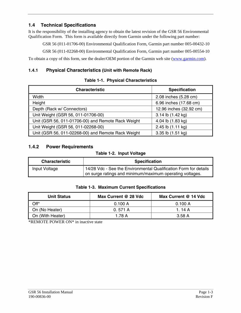
To obtain a copy of this form, see the dealer/OEM portion of the Garmin web site (www.garmin.com). 1.4.1 Physical Characteristics (Unit with Remote Rack)
Table 1-1. Physical Characteristics
Characteristic Specification
Width 2.08 inches (5.28 cm) Height 6.96 inches (17.68 cm) Depth (Rack w/ Connectors) 12.96 inches (32.92 cm) Unit Weight (GSR 56, 011-01706-00) 3.14 lb (1.42 kg) Unit (GSR 56, 011-01706-00) and Remote Rack Weight 4.04 lb (1.83 kg) Unit Weight (GSR 56, 011-02268-00) 2.45 lb (1.11 kg) Unit (GSR 56, 011-02268-00) and Remote Rack Weight 3.35 lb (1.51 kg)
1.4.2 Power Requirements Table 1-2. Input Voltage
Characteristic Specification
Input Voltage 14/28 Vdc - See the Environmental Qualification Form for details on surge ratings and minimum/maximum operating voltages.
Table 1-3. Maximum Current Specifications
Unit Status Max Current @ 28 Vdc Max Current @ 14 Vdc
Off* 0.100 A 0.100 A On (No Heater) 0. 571 A 1. 14 A On (With Heater) 1.78 A 3.58 A
*REMOTE POWER ON* in inactive state

Page 1-4 GSR 56 Installation Manual Revision F 190-00836-00
1.4.3 General Specifications
Table 1-4. General Specifications
Characteristics Specifications
Operating Temperature Range (011-01706-00)
-15°C to +60°C. For more details see Environmental Qualification Form.
Operating Temperature Range (011-02268-00)
-15°C to +70°C. For more details see Environmental Qualification Form.
Humidity 95% non-condensing Altitude Range -1,500 ft to 55,000 ft Software Compliance RTCA/DO-178B Level E
1.4.4 General Iridium Antenna Requirements
Table 1-5. Iridium Antenna Minimum Requirements
Characteristics Specifications
Frequency Range 1616 to 1626.5 MHz Gain (Typical) 3dBnc Polarization Right Hand Circular Polarization (RHCP) Nominal Output Impedance 50 ohms Operating Temperature Gain -50 to +85°C* Antenna Cable Loss (transmit and receive) 3.0dB Max
*STC/Installation dependent
1.5 Approved Antennas
Only antennas from a list of Iridium-approved antenna available from the Iridium website at http://www.iridium.com are approved for use with the GSR 56. This list currently includes:
1. Comant CI 490-1 2. Sensor System S67-1575-165 3. Antcom S3IR16RR 4. Dayton Granger L10-780 5. Dayton Granger L10-787

GSR 56 Installation Manual Page 1-5 190-00836-00 Revision F
1.6 Certification
The conditions and tests required for the TSO approval of this article are minimum performance standards. It is the responsibility of those installing this article either on or within a specific type or class of aircraft to determine that the aircraft installation conditions are within the TSO standards. TSO articles must have separate approval installation in an aircraft. The article may be installed only if performed under 14 CFR part 43 or the applicable airworthiness requirements.
The Appliance Project Identifier (API) for the GSR 56 is GMN-00641. The API has been used for project identification with the FAA and EASA. In addition, the alpha character appended to the API in the ETSO certificate has been added to supplement project identification by EASA. This alpha character does not represent a version number; see applicable hardware and software part numbers to identify appliance approvals.
The GSR 56 system is limited to communication to the cockpit and cabin for convenience only.
1.6.1 TSO/ETSO Compliance
1.6.1.1 GSR 56 (011-01706-00)
Table 1-6. TSO/ETSO Authorizations
Function TSO/ETSO Category
Aircraft Audio Systems and Equipment TSO-C139 Audio Selector Panels and Amplifier ETSO-C50c Airborne Systems for Non Required Telecommunication Services (In Non Aeronautical Frequency Bands)
ETSO-2C514 Class 2/Category 1
1.6.1.2 GSR 56 (011-02268-00)
Table 1-7. TSO/ETSO Authorizations
Function TSO Category
Aircraft Audio Systems and Equipment TSO-C139 Audio Selector Panels and Amplifier ETSO-C50c Airborne Systems for Non Required Telecommunication Services (In Non Aeronautical Frequency Bands)
ETSO-2C514 Class 2/Category 1

Page 1-6 GSR 56 Installation Manual Revision F 190-00836-00
1.6.2 TSO/ETSO Deviations
1.6.2.1 GSR 56 (011-01706-00)
Table 1-8. TSO/ETSO Deviations
TSO/ETSO Deviation
1. Garmin was granted a deviation from TSO-C139 subpart 3b to consider failure of the intended function of the GSR56, defined in the stated paragraph of TSO-C139, as no safety effect. 2. Garmin was granted a deviation from TSO-C139 to use the environmental qualification form as part of RTCA DO-160E instead of the form required as part of DO-160D. 3. Garmin was granted a deviation from TSO-C139 subpart 7a which requires furnishing each person receiving a GSR 56 copy of the data listed in paragraph 5l of TSO-C139.
TSO-C139
4. Garmin was granted a deviation from TSO-C139 subpart 7b which requires furnishing each person receiving a GSR 56 a copy of the data in paragraphs 5l, 5m, and 5n of TSO-C139. 1. Garmin was granted a deviation from ETSO-C50c § 3.1.2 to use EUROCAE ED-14E/ RTCA DO-160E instead of ED-14D/ RTCA DO-160D as the environmental test standard.
ETSO-C50c
2. Garmin was granted a deviation from ETSO-C50c § 3.1.1 to use RTCA DO-214 instead of EUROCAE ED-18/RTCA DO-170 as the Minimum Performance Standard.
1.6.2.2 GSR 56 (011-02268-00)
Table 1-9. TSO/ETSO Deviations
TSO/ETSO Deviation
1. Garmin was granted a deviation from TSO-C139 subpart 3b to consider failure of the intended function of the GSR56, defined in the stated paragraph of TSO-C139, as no safety effect. 2. Garmin was granted a deviation from TSO-C139 to use the environmental qualification form as part of RTCA DO-160E instead of the form required as part of DO-160D. 3. Garmin was granted a deviation from TSO-C139 subpart 7a which requires furnishing each person receiving a GSR 56 copy of the data listed in paragraph 5l of TSO-C139.
TSO-C139
4. Garmin was granted a deviation from TSO-C139 subpart 7b which requires furnishing each person receiving a GSR 56 a copy of the data in paragraphs 5l, 5m, and 5n of TSO-C139. 1. Garmin was granted a deviation from ETSO-C50c § 3.1.2 to use EUROCAE ED-14E/ RTCA DO-160E instead of ED-14D/ RTCA DO-160D as the environmental test standard.
ETSO-C50c
2. Garmin was granted a deviation from ETSO-C50c § 3.1.1 to use RTCA DO-214 instead of EUROCAE ED-18/RTCA DO-170 as the Minimum Performance Standard.

GSR 56 Installation Manual Page 1-7 190-00836-00 Revision F
1.6.3 Non-TSO Functions
The non-TSO function listed in Table 1-10 was tested to RTCA/DO-160E environmental qualifications.
Table 1-10. Non-TSO Functions
Function Design Assurance
Iridium satellite radio transceiver RTCA/DO-178B Level E
1.7 Reference Documentation
The publications listed in Table 1-11 are sources of additional information for installing the GSR 56. Before installing the GSR 56, the technician should read all referenced materials applicable to the installation along with this manual.
Table 1-11. Referenced Publications
Part Number Document
005-00432-10 GSR 56 (011-01706-00) Environmental Qualification Form 005-00554-10 GSR 56 (011-02268-00) Environmental Qualification Form 190-00303-00 G1000 System Installation Manual 190-00303-04 G1000 Line Maintenance and Configuration Manual
Page 1-8 GSR 56 Installation Manual Revision F 190-00836-00
1.8 Aviation Limited Warranty
All Garmin avionics products are warranted to be free from defects in materials or workmanship for: two years from the date of purchase for new Remote-Mount and Panel-Mount products; one year from the date of purchase for new portable products and any purchased newly-overhauled products; six months for newly-overhauled products exchanged through a Garmin Authorized Service Center; and 90 days for factory repaired or newly-overhauled products exchanged at Garmin in lieu of repair. Within the applicable period, Garmin will, at its sole option, repair or replace any components that fail in normal use. Such repairs or replacement will be made at no charge to the customer for parts or labor, provided that the customer shall be responsible for any transportation cost. This warranty does not apply to: (i) cosmetic damage, such as scratches, nicks and dents; (ii) consumable parts, such as batteries, unless product damage has occurred due to a defect in materials or workmanship; (iii) damage caused by accident, abuse, misuse, water, flood, fire, or other acts of nature or external causes; (iv) damage caused by service performed by anyone who is not an authorized service provider of Garmin; or (v) damage to a product that has been modified or altered without the written permission of Garmin. In addition, Garmin reserves the right to refuse warranty claims against products or services that are obtained and/or used in contravention of the laws of any country.
THE WARRANTIES AND REMEDIES CONTAINED HEREIN ARE EXCLUSIVE AND IN LIEU OF ALL OTHER WARRANTIES, WHETHER EXPRESS, IMPLIED OR STATUTORY, INCLUDING ANY LIABILITY ARISING UNDER ANY WARRANTY OF MERCHANTABILITY OR FITNESS FOR A PARTICULAR PURPOSE, STATUTORY OR OTHERWISE. THIS WARRANTY GIVES YOU SPECIFIC LEGAL RIGHTS, WHICH MAY VARY FROM STATE TO STATE.
IN NO EVENT SHALL GARMIN BE LIABLE FOR ANY INCIDENTAL, SPECIAL, INDIRECT OR CONSEQUENTIAL DAMAGES, WHETHER RESULTING FROM THE USE, MISUSE OR INABILITY TO USE THE PRODUCT OR FROM DEFECTS IN THE PRODUCT. SOME STATES DO NOT ALLOW THE EXCLUSION OF INCIDENTAL OR CONSEQUENTIAL DAMAGES, SO THE ABOVE LIMITATIONS MAY NOT APPLY TO YOU.
Garmin retains the exclusive right to repair or replace (with a new or newly-overhauled replacement product) the product or software or offer a full refund of the purchase price at its sole discretion. SUCH REMEDY SHALL BE YOUR SOLE AND EXCLUSIVE REMEDY FOR ANY BREACH OF WARRANTY.
Online Auction Purchases: Products purchased through online auctions are not eligible for warranty coverage. Online auction confirmations are not accepted for warranty verification. To obtain warranty service, an original or copy of the sales receipt from the original retailer is required. Garmin will not replace missing components from any package purchased through an online auction.
International Purchases: A separate warranty may be provided by international distributors for devices purchased outside the United States depending on the country. If applicable, this warranty is provided by the local in-country distributor and this distributor provides local service for your device. Distributor warranties are only valid in the area of intended distribution. Devices purchased in the United States or Canada must be returned to the Garmin service center in the United Kingdom, the United States, Canada, or Taiwan for service.
Garmin International, Inc. Garmin (Europe) Ltd. 1200 East 151st Street Liberty House, Bulls Copse Road Olathe, Kansas 66062, U.S.A. Hounsdown Business Park Phone: 913/397.8200 Romsey, SO40 9RB, U.K.
FAX: 913/397.0836 Phone: 44/ (0) 870.8501241 FAX: 44/ (0) 870.850125
GSR 56 Installation Manual Page 2-1 190-00836-00 Revision F
2 INSTALLATION
2.1 Introduction
This section provides hardware equipment information for installing the GSR 56 and related hardware. Installation of the GSR 56 should follow the aircraft TC or STC requirements. Cabling is fabricated by the installing agency to fit each particular aircraft. The guidance of FAA advisory circulars AC 43.13-1B and AC 43.13-2A, where applicable, may be found useful for making retro-fit installations that comply with FAA regulations.
Refer to the G1000 System Installation Manual, Garmin part number 190-00303-00 for further details on the mechanical aspects.
2.2 Installation Materials
The GSR 56 is available as a single unit under the part numbers listed in Table 2-1.
Table 2-1. Unit Part Numbers
Item Garmin Catalog Part Number
GSR 56 Unit (011-01706-00) 010-00641-00
GSR 56 Unit (011-02268-00) 010-00815-00
2.3 Equipment Available
Each of the accessories listed in Table 2-2 are available separately for the GSR 56.
Table 2-2. Accessories
Item Garmin Catalog Part Number
GSR 56 Unit Rack, Remote 115-01018-00 GSR 56 Back Plate 011-01800-00 GSR 56 Connector Kit 011-01732-00
2.4 Cabling and Wiring
Use AWG #24 or larger wire for all connections unless otherwise specified by the aircraft manufacturer or Garmin. The standard pin contacts supplied in the connector kit are compatible with 22, 24, 26, & 28 AWG wire. In cases where some installations have more than one unit sharing a common circuit breaker, sizing and wire gauge is based on aircraft circuit breaker layout, length of wiring, current draw of units, and internal unit protection characteristics. Do not attempt to combine more than one unit on the same circuit breaker unless it is specified on aircraft manufacturer approved drawings.
In some cases, a larger gauge wire such as 16 or 18 AWG may be needed for power connections. 16 & 18 AWG compatible pins are provided in the connector kit for these power and ground connections. Special thin-wall heat shrink tubing is also provided to insulate the extended barrels inside the backshell. If using #16 or #18 barrel contacts, ensure that no two contacts are mounted directly adjacent to each other. This minimizes the risk of contacts touching and shorting to adjacent pins and to ground.
Ensure that routing of the wiring does not come in contact with sources of heat or RF/EMI interference. Check that there is ample space for the cabling and mating connectors. Avoid sharp bends in cabling and routing near aircraft control cables.
Page 2-2 GSR 56 Installation Manual Revision F 190-00836-00
2.5 Cooling Air
No cooling air is needed for the GSR 56.
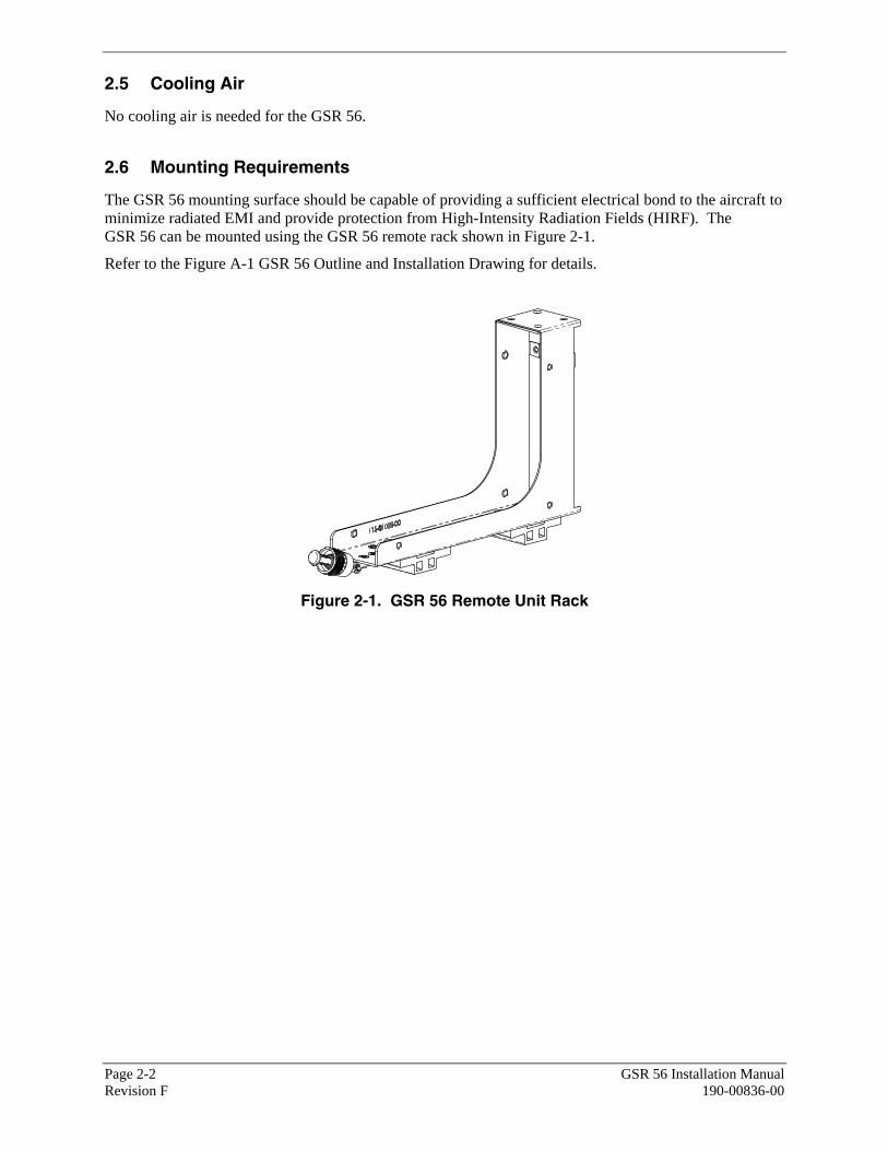
2.6 Mounting Requirements
The GSR 56 mounting surface should be capable of providing a sufficient electrical bond to the aircraft to minimize radiated EMI and provide protection from High-Intensity Radiation Fields (HIRF). The GSR 56 can be mounted using the GSR 56 remote rack shown in Figure 2-1.
Refer to the Figure A-1 GSR 56 Outline and Installation Drawing for details.
Figure 2-1. GSR 56 Remote Unit Rack
GSR 56 Installation Manual Page 3-1 190-00836-00 Revision F
3 INSTALLATION PROCEDURE
3.1 Unpacking Unit
Carefully unpack the equipment and make a visual inspection of the unit for evidence of damage incurred during shipment. If the unit is damaged, notify the carrier and file a claim. To justify a claim, save the original shipping container and all packing materials. Do not return the unit to Garmin until the carrier has authorized the claim.
Retain the original shipping containers for storage. If the original containers are not available, a separate cardboard container should be prepared that is large enough to accommodate sufficient packing material to prevent movement.
3.2 Wiring Harness Installation
Allow adequate space for installation of cables and connectors. The installer shall supply and fabricate all of the cables. Electrical connections are made through a 44-pin D-Subminiature connector and a TNC coaxial connector.
Section 4 defines the electrical characteristics of all input and output signals. Required connectors and associated hardware are supplied with the connector kit (Refer to Section 2.3). See Appendix B for examples of interconnect wiring diagrams. Construct the actual harnesses in accordance with aircraft specific approved interconnect diagrams.
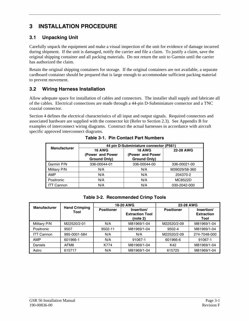
Table 3-1. Pin Contact Part Numbers
44 pin D-Subminiature connector (P561) Manufacturer 16 AWG
(Power and Power Ground Only)
18 AWG (Power and Power
Ground Only)
22-28 AWG
Garmin P/N 336-00044-01 336-00044-00 336-00021-00 Military P/N N/A N/A M39029/58-360 AMP N/A N/A 204370-2 Positronic N/A N/A MC8522D ITT Cannon N/A N/A 030-2042-000
Table 3-2. Recommended Crimp Tools
18-20 AWG 22-28 AWG Manufacturer Hand Crimping
Tool Positioner Insertion/
Extraction Tool (note 2)
Positioner Insertion/ Extraction
Tool Military P/N M22520/2-01 N/A M81969/1-04 M22520/2-09 M81969/1-04
Positronic 9507 9502-11 M81969/1-04 9502-4 M81969/1-04
ITT Cannon 995-0001-584 N/A N/A M22520/2-09 274-7048-000
AMP 601966-1 N/A 91067-1 601966-6 91067-1
Daniels AFM8 K774 M81969/1-04 K42 M81969/1-04
Astro 615717 N/A M81969/1-04 615725 M81969/1-04
Page 3-2 GSR 56 Installation Manual Revision F 190-00836-00
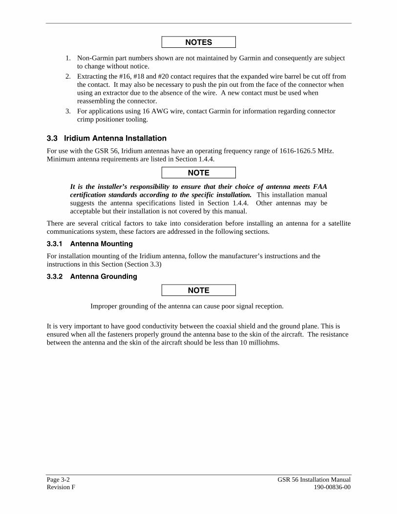
NOTES
1. Non-Garmin part numbers shown are not maintained by Garmin and consequently are subject to change without notice.
2. Extracting the #16, #18 and #20 contact requires that the expanded wire barrel be cut off from the contact. It may also be necessary to push the pin out from the face of the connector when using an extractor due to the absence of the wire. A new contact must be used when reassembling the connector.
3. For applications using 16 AWG wire, contact Garmin for information regarding connector crimp positioner tooling.
3.3 Iridium Antenna Installation
For use with the GSR 56, Iridium antennas have an operating frequency range of 1616-1626.5 MHz. Minimum antenna requirements are listed in Section 1.4.4.
NOTE
It is the installer’s responsibility to ensure that their choice of antenna meets FAA certification standards according to the specific installation. This installation manual suggests the antenna specifications listed in Section 1.4.4. Other antennas may be acceptable but their installation is not covered by this manual.
There are several critical factors to take into consideration before installing an antenna for a satellite communications system, these factors are addressed in the following sections.
3.3.1 Antenna Mounting
For installation mounting of the Iridium antenna, follow the manufacturer’s instructions and the instructions in this Section (Section 3.3)
3.3.2 Antenna Grounding
NOTE
Improper grounding of the antenna can cause poor signal reception.
It is very important to have good conductivity between the coaxial shield and the ground plane. This is ensured when all the fasteners properly ground the antenna base to the skin of the aircraft. The resistance between the antenna and the skin of the aircraft should be less than 10 milliohms.

GSR 56 Installation Manual Page 3-3 190-00836-00 Revision F
3.3.3 Iridium Antenna Location
As with any antenna installation, keep the following points in mind:
1. The Iridium Satellite signal is a line-of-sight signal. Locating antennas too close to obstructions such as the vertical stabilizer will limit the reception of the satellite signal.
2. Maintain about three feet from heater, ignition, autopilot, and other control surface actuators and motors. Maintain about five feet from fluorescent lamps, related ballast, air conditioners, blowers, strobe lights and power supplies.
3. The minimum distances to be observed when selecting an antenna location are as follows:
• 30 inches from any passive (receive only) antenna such as GPS. • 5 inches from a VHF active antenna such as COM or ACARS. • 5 inches from an active radar altimeter (4 GHz). • 30 inches from a UHF / Microwave transmitting antenna such as a transponder, DME, active
TCAS, UAT, SATCOM, or Flitephone. • 34 inches between the Iridium Antenna for dual or multiple Iridium GSR 56 installations.
4. The Iridium antenna must be mounted on top of the aircraft for greatest satellite visibility (Figure 3-1). For best performance, select a location with an unobstructed view of the sky above the aircraft when in level flight. Location of communication antennas too close to the Iridium antenna may not only degrade the transmission through reflection, but can also absorb and re-radiate the transmission causing a condition similar to having two COM antennas located in close proximity to each other.
Figure 3-1. Antenna Installation Location
Page 3-4 GSR 56 Installation Manual Revision F 190-00836-00
3.4 Cable Installation
3.4.1 Coaxial Cable Installation
1. Choose the correct coax: RG-400/U has good characteristics for loss, size, and flexibility. The maximum cable loss between the GSR 56 and the satellite antenna (transmit or receive) is 3.0 dB.
NOTE
It is critical to the performance of the GSR 56 to keep the cable loss of the antenna cable to a minimum through the use of appropriate coax cable and proper connector installation. The total RF loss should not exceed 3.0 dB @ 1600 Mhz and the VSWR should be less than 1.4:1 when the cable is terminated in a 50 ohm load.
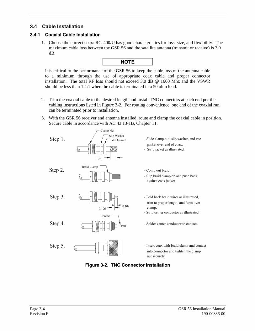
2. Trim the coaxial cable to the desired length and install TNC connectors at each end per the
cabling instructions listed in Figure 3-2. For routing convenience, one end of the coaxial run can be terminated prior to installation.
3. With the GSR 56 receiver and antenna installed, route and clamp the coaxial cable in position. Secure cable in accordance with AC 43.13-1B, Chapter 11.
Figure 3-2. TNC Connector Installation
GSR 56 Installation Manual Page 3-5 190-00836-00 Revision F
3.5 Backshell Assembly and Installation
The GSR 56 connector kit includes a Garmin backshell assembly. Garmin’s backshell also gives the installer the ability to easily terminate shield grounds at the backshell housing using the Shield Block method. To assemble the backshell refer to instructions provided in the G1000 System Installation Manual (190-00303-00) and Shield Block Installation Instructions (190-00313-09).
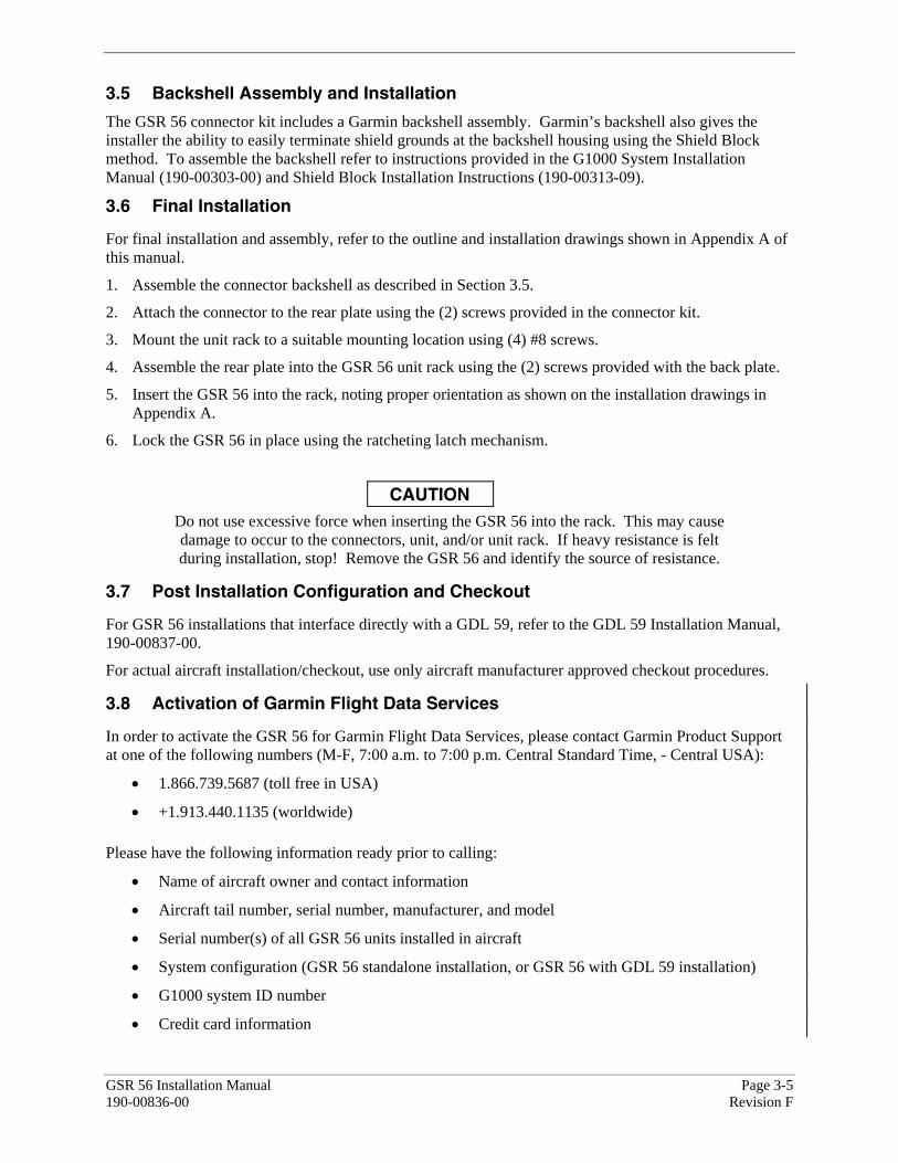
3.6 Final Installation
For final installation and assembly, refer to the outline and installation drawings shown in Appendix A of this manual.
1. Assemble the connector backshell as described in Section 3.5.
2. Attach the connector to the rear plate using the (2) screws provided in the connector kit.
3. Mount the unit rack to a suitable mounting location using (4) #8 screws.
4. Assemble the rear plate into the GSR 56 unit rack using the (2) screws provided with the back plate.
5. Insert the GSR 56 into the rack, noting proper orientation as shown on the installation drawings in Appendix A.
6. Lock the GSR 56 in place using the ratcheting latch mechanism.
CAUTION Do not use excessive force when inserting the GSR 56 into the rack. This may cause damage to occur to the connectors, unit, and/or unit rack. If heavy resistance is felt during installation, stop! Remove the GSR 56 and identify the source of resistance.
3.7 Post Installation Configuration and Checkout
For GSR 56 installations that interface directly with a GDL 59, refer to the GDL 59 Installation Manual, 190-00837-00.
For actual aircraft installation/checkout, use only aircraft manufacturer approved checkout procedures.
3.8 Activation of Garmin Flight Data Services
In order to activate the GSR 56 for Garmin Flight Data Services, please contact Garmin Product Support at one of the following numbers (M-F, 7:00 a.m. to 7:00 p.m. Central Standard Time, - Central USA):
• 1.866.739.5687 (toll free in USA)
• +1.913.440.1135 (worldwide)
Please have the following information ready prior to calling:
• Name of aircraft owner and contact information
• Aircraft tail number, serial number, manufacturer, and model
• Serial number(s) of all GSR 56 units installed in aircraft
• System configuration (GSR 56 standalone installation, or GSR 56 with GDL 59 installation)
• G1000 system ID number
• Credit card information
Page 3-6 GSR 56 Installation Manual Revision F 190-00836-00
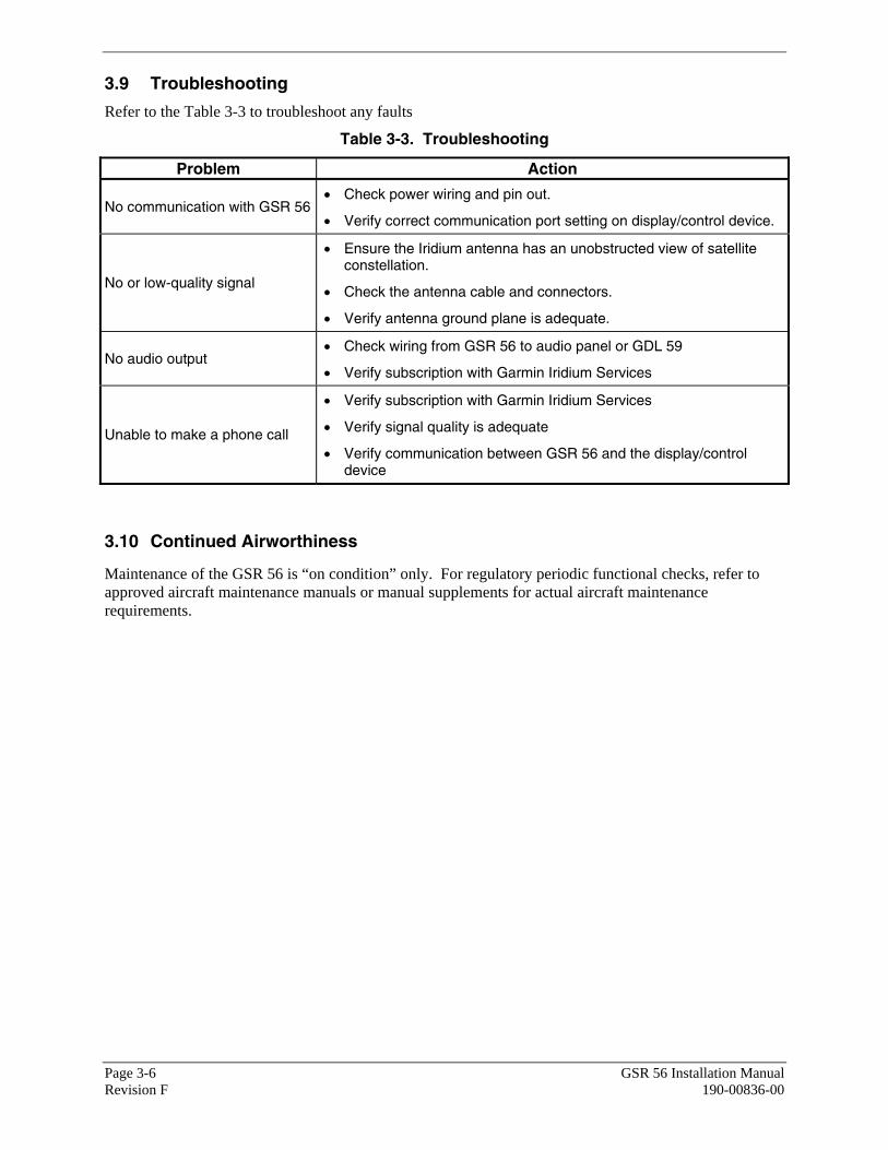
3.9 Troubleshooting
Refer to the Table 3-3 to troubleshoot any faults
Table 3-3. Troubleshooting
Problem Action
No communication with GSR 56 • Check power wiring and pin out.
• Verify correct communication port setting on display/control device.
No or low-quality signal
• Ensure the Iridium antenna has an unobstructed view of satellite constellation.
• Check the antenna cable and connectors.
• Verify antenna ground plane is adequate.
No audio output • Check wiring from GSR 56 to audio panel or GDL 59
• Verify subscription with Garmin Iridium Services
Unable to make a phone call
• Verify subscription with Garmin Iridium Services
• Verify signal quality is adequate
• Verify communication between GSR 56 and the display/control device
3.10 Continued Airworthiness
Maintenance of the GSR 56 is “on condition” only. For regulatory periodic functional checks, refer to approved aircraft maintenance manuals or manual supplements for actual aircraft maintenance requirements.

GSR 56 Installation Manual Page 4-1 190-00836-00 Revision F
4 SYSTEM INTERCONNECTS
4.1 Pin Function List
4.1.1 P561 Connector
View of J561 connector looking at unit 123456789101112131415
161718192021222324252627282930
3132333435363738394041424344
Pin Pin Name I/O 1 AUDIO OUT HI Out 2 AUDIO OUT LO Out 3 POWER GROUND -- 4 AUDIO IN HI In 5 AUDIO IN LO In 6 POWER GROUND -- 7 RESERVED -- 8 RESERVED -- 9 RESERVED --
10 RESERVED -- 11 SIGNAL GROUND -- 12 RS-232 OUT Out 13 RS-232 IN In 14 SIGNAL GROUND -- 15 RESERVED -- 16 IRIDIUM REMOTE POWER ON* In 17 POWER GROUND -- 18 RESERVED -- 19 POWER GROUND -- 20 RESERVED -- 21 HEATER POWER In 22 HEATER 1 HI -- 23 POWER GROUND -- 24 SPARE -- 25 RESERVED -- 26 RESERVED -- 27 RESERVED -- 28 RESERVED -- 29 RESERVED -- 30 RESERVED -- 31 STATUS DISCRETE* OUT Out 32 AIRCRAFT POWER 1 In 33 AIRCRAFT POWER 1 In 34 AIRCRAFT POWER 2 In
*Denotes Active Low (Ground to activate)
Page 4-2 GSR 56 Installation Manual Revision F 190-00836-00
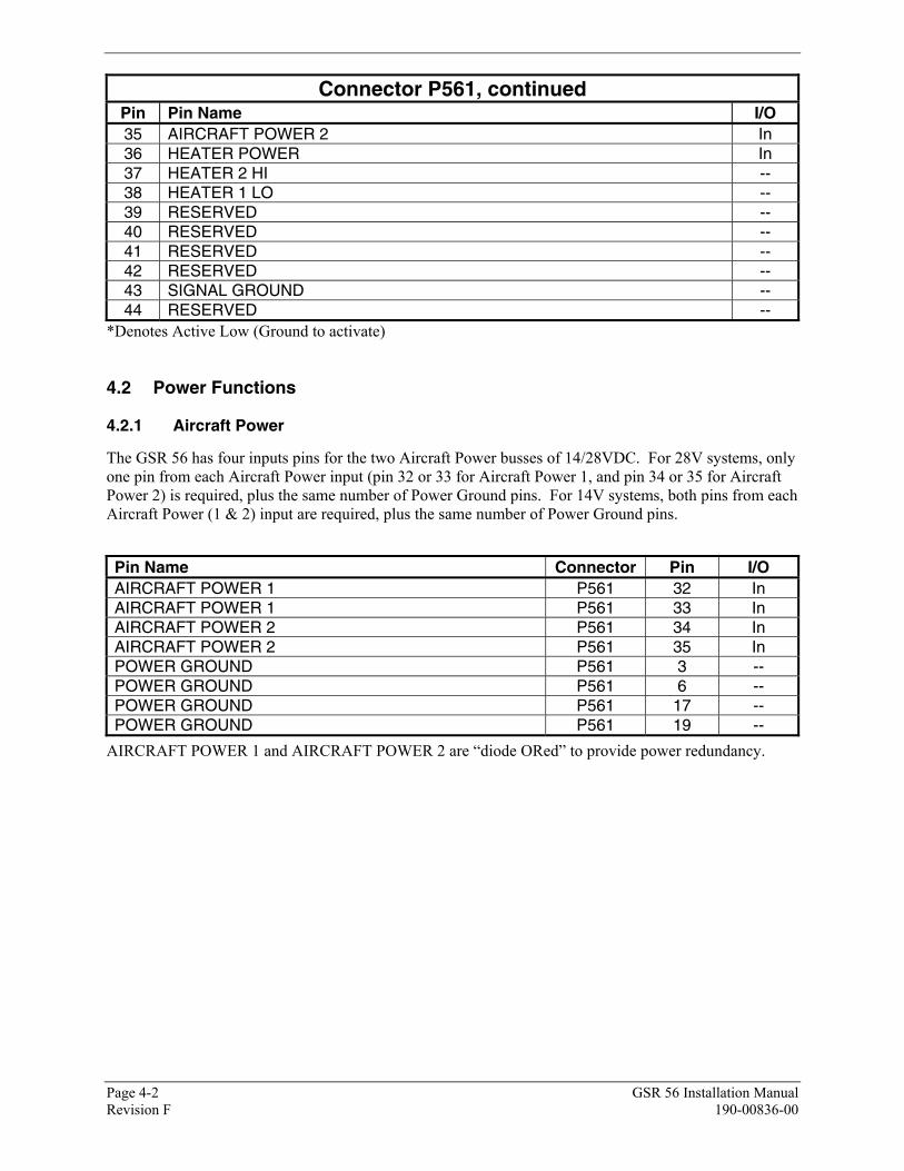
Connector P561, continued Pin Pin Name I/O 35 AIRCRAFT POWER 2 In 36 HEATER POWER In 37 HEATER 2 HI -- 38 HEATER 1 LO -- 39 RESERVED -- 40 RESERVED -- 41 RESERVED -- 42 RESERVED -- 43 SIGNAL GROUND -- 44 RESERVED --
*Denotes Active Low (Ground to activate)
4.2 Power Functions
4.2.1 Aircraft Power
The GSR 56 has four inputs pins for the two Aircraft Power busses of 14/28VDC. For 28V systems, only one pin from each Aircraft Power input (pin 32 or 33 for Aircraft Power 1, and pin 34 or 35 for Aircraft Power 2) is required, plus the same number of Power Ground pins. For 14V systems, both pins from each Aircraft Power (1 & 2) input are required, plus the same number of Power Ground pins.
Pin Name Connector Pin I/O AIRCRAFT POWER 1 P561 32 In AIRCRAFT POWER 1 P561 33 In AIRCRAFT POWER 2 P561 34 In AIRCRAFT POWER 2 P561 35 In POWER GROUND P561 3 -- POWER GROUND P561 6 -- POWER GROUND P561 17 -- POWER GROUND P561 19 --
AIRCRAFT POWER 1 and AIRCRAFT POWER 2 are “diode ORed” to provide power redundancy.
GSR 56 Installation Manual Page 4-3 190-00836-00 Revision F
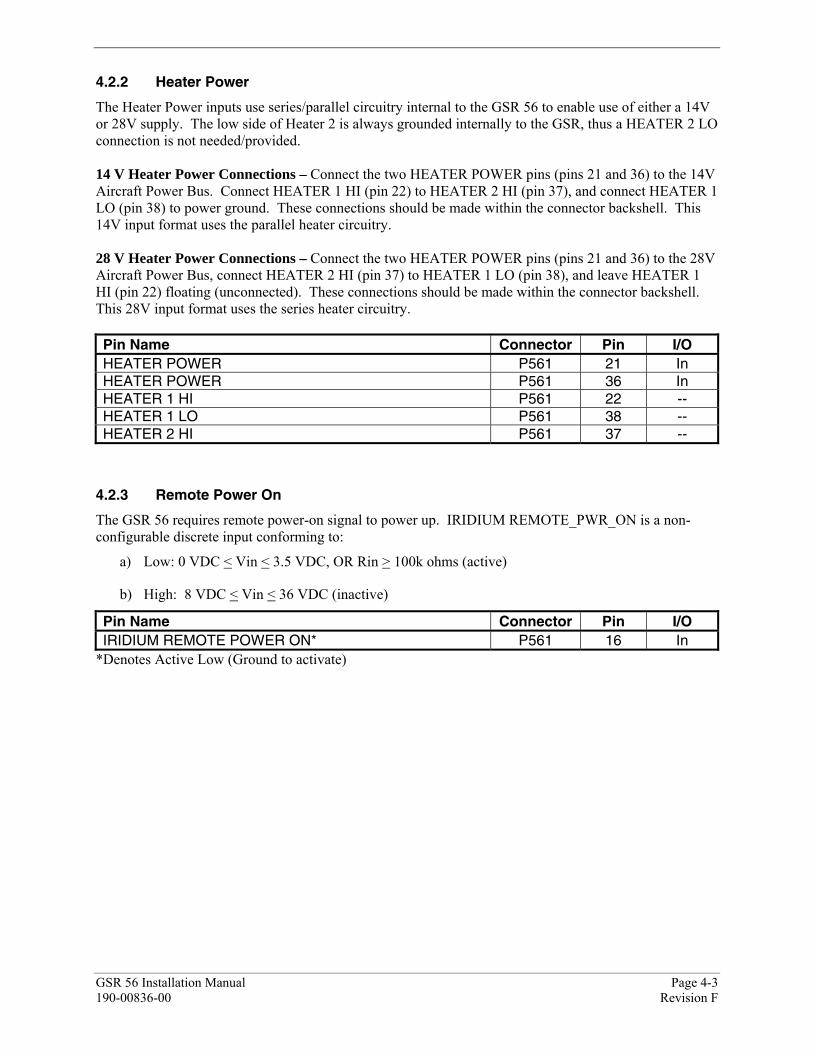
4.2.2 Heater Power
The Heater Power inputs use series/parallel circuitry internal to the GSR 56 to enable use of either a 14V or 28V supply. The low side of Heater 2 is always grounded internally to the GSR, thus a HEATER 2 LO connection is not needed/provided. 14 V Heater Power Connections – Connect the two HEATER POWER pins (pins 21 and 36) to the 14V Aircraft Power Bus. Connect HEATER 1 HI (pin 22) to HEATER 2 HI (pin 37), and connect HEATER 1 LO (pin 38) to power ground. These connections should be made within the connector backshell. This 14V input format uses the parallel heater circuitry. 28 V Heater Power Connections – Connect the two HEATER POWER pins (pins 21 and 36) to the 28V Aircraft Power Bus, connect HEATER 2 HI (pin 37) to HEATER 1 LO (pin 38), and leave HEATER 1 HI (pin 22) floating (unconnected). These connections should be made within the connector backshell. This 28V input format uses the series heater circuitry. Pin Name Connector Pin I/O HEATER POWER P561 21 In HEATER POWER P561 36 In HEATER 1 HI P561 22 -- HEATER 1 LO P561 38 -- HEATER 2 HI P561 37 --
4.2.3 Remote Power On
The GSR 56 requires remote power-on signal to power up. IRIDIUM REMOTE_PWR_ON is a non-configurable discrete input conforming to:
a) Low: 0 VDC < Vin < 3.5 VDC, OR Rin > 100k ohms (active)
b) High: 8 VDC < Vin < 36 VDC (inactive)
Pin Name Connector Pin I/O IRIDIUM REMOTE POWER ON* P561 16 In
*Denotes Active Low (Ground to activate)
Page 4-4 GSR 56 Installation Manual Revision F 190-00836-00
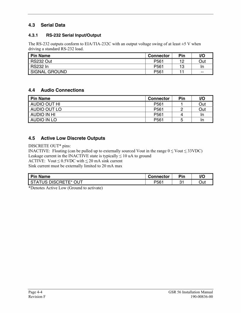
4.3 Serial Data
4.3.1 RS-232 Serial Input/Output
The RS-232 outputs conform to EIA/TIA-232C with an output voltage swing of at least ±5 V when driving a standard RS-232 load. Pin Name Connector Pin I/O RS232 Out P561 12 Out RS232 In P561 13 In SIGNAL GROUND P561 11 --
4.4 Audio Connections
Pin Name Connector Pin I/O AUDIO OUT HI P561 1 Out AUDIO OUT LO P561 2 Out AUDIO IN HI P561 4 In AUDIO IN LO P561 5 In
4.5 Active Low Discrete Outputs
DISCRETE OUT* pins: INACTIVE: Floating (can be pulled up to externally sourced Vout in the range 0 ≤ Vout ≤ 33VDC) Leakage current in the INACTIVE state is typically ≤ 10 uA to ground ACTIVE: Vout ≤ 0.5VDC with ≤ 20 mA sink current Sink current must be externally limited to 20 mA max Pin Name Connector Pin I/O STATUS DISCRETE* OUT P561 31 Out
*Denotes Active Low (Ground to activate)
APPENDIX A OUTLINE AND INSTALLATION DRAWINGS
GSR 56 Installation Manual Page A-1 (Page A-2 Blank) 190-00836-00 Revision F
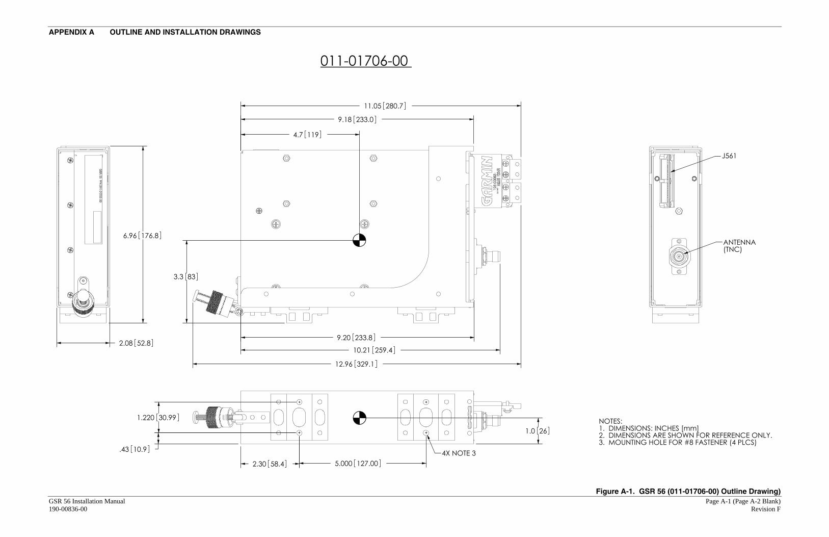
3.3 83
4.7 119
1.0 26
J561
ANTENNA(TNC)
10.21 259.4
233.09.18
233.89.20
329.112.96
11.05 280.7
4X NOTE 3
1.220 30.99
127.005.00058.42.30
.43 10.9
NOTES:1. DIMENSIONS: INCHES [mm]2. DIMENSIONS ARE SHOWN FOR REFERENCE ONLY.3. MOUNTING HOLE FOR #8 FASTENER (4 PLCS)
011-01706-00
2.08 52.8
6.96 176.8
Figure A-1. GSR 56 (011-01706-00) Outline Drawing)
APPENDIX A OUTLINE AND INSTALLATION DRAWINGS
GSR 56 Installation Manual Page A-3 (Page A-4 Blank) 190-00836-00 Revision F
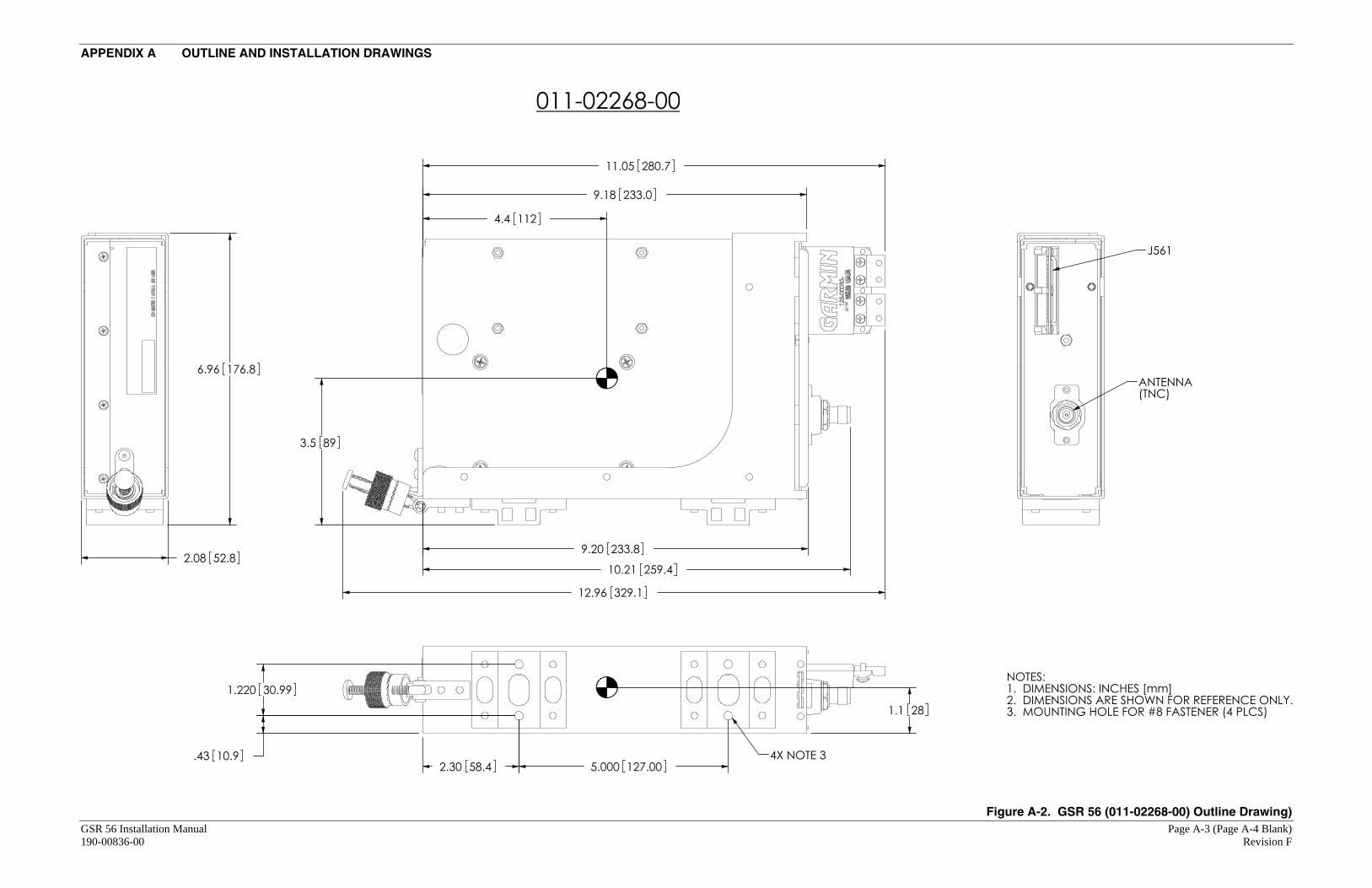
1.1 28
3.5 89
4.4 112
4X NOTE 35.000 127.002.30 58.4
1.220 30.99
.43 10.9
9.18 233.0
9.20 233.8
12.96 329.1
10.21 259.4
11.05 280.7
J561
ANTENNA(TNC)
6.96 176.8
2.08 52.8
NOTES:1. DIMENSIONS: INCHES [mm]2. DIMENSIONS ARE SHOWN FOR REFERENCE ONLY.3. MOUNTING HOLE FOR #8 FASTENER (4 PLCS)
011-02268-00
Figure A-2. GSR 56 (011-02268-00) Outline Drawing)
APPENDIX A OUTLINE AND INSTALLATION DRAWINGS
GSR 56 Installation Manual Page A-5 (Page A-6 Blank) 190-00836-00 Revision F
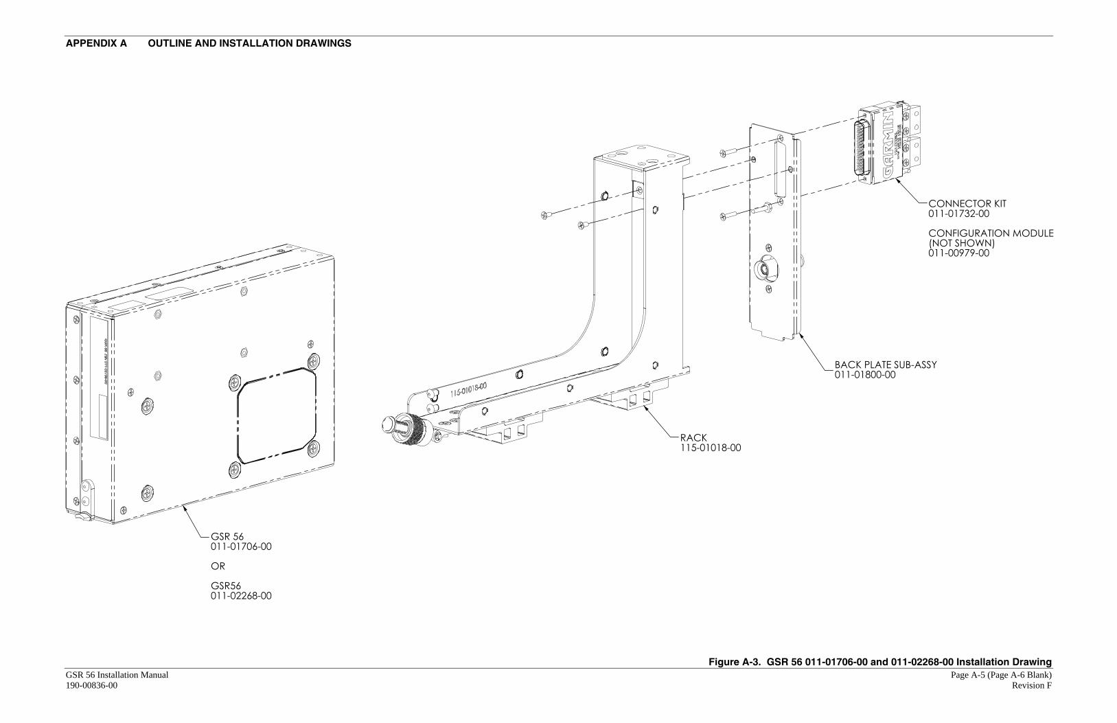
GSR 56011-01706-00
OR
GSR56011-02268-00
RACK115-01018-00
BACK PLATE SUB-ASSY011-01800-00
CONNECTOR KIT011-01732-00
CONFIGURATION MODULE(NOT SHOWN)011-00979-00
Figure A-3. GSR 56 011-01706-00 and 011-02268-00 Installation Drawing

APPENDIX B INTERCONNECT DRAWING
GSR 56 Installation Manual Page B-1 (Page B-2 Blank) 190-00836-00 Revision F
3233
317
GSR 56 TRANSCEIVER GSR 56
ANT
P5661
AIRCRAFT POWER 1AIRCRAFT POWER 1
POWER GROUNDPOWER GROUND
AUDIO IN LOAUDIO IN HI
54 WHT
BLU
AUDIO OUT LOAUDIO OUT HI
BLUWHT
21
IRIDIUM REMOTE POWER ON* 16
RS-232 OUT
RS-232 IN
12
13
BLUWHT
BLUWHT
S
ORNBLUWHT
ORNBLUWHT
SIGNAL GROUND 14
31STATUS DISCRETE* OUT
GDL 59 DATALINKP591
IRIDIUM 1 REMOTE POWER ON*73
IRIDIUM AUDIO 1 OUT HIIRIDIUM AUDIO 1 OUT LO
IRIDIUM AUDIO 1 IN HIIRIDIUM AUDIO 1IN LO
1635
1534
RS 232 OUT 1SIGNAL GROUNDRS 232 IN 1
634464
56 IRIDIUM 1 STATUS DISCRETE* IN
S
SIRIDIUMANTENNA
21363822
GSR 56 TRANSCEIVER GSR 56P5661
HEATER POWER 14 VDCHEATER POWER
HEATER 1 LOHEATER 1 HIHEATER 2 HI 37
14 VDC HEATER POWER CONNECTIONS
21363837
GSR 56 TRANSCEIVER GSR 56P5661
HEATER POWER 28 VDCHEATER POWER
HEATER 1 LOHEATER 2 HIHEATER 1 HI 22 FLOATING
28 VDC HEATER POWER CONNECTIONS
3A
1A
2A
P562
28 VDC
Figure B-1. GSR 56 Example Interconnect


![OPENBOX X810 Digital Satellite Receiver[1]](https://static.fdocuments.in/doc/165x107/54f8d43b4a7959b5608b460f/openbox-x810-digital-satellite-receiver1.jpg)