Satellite Navigation
35
Page | 1 UNIVERSITY OF PETROLEUM AND ENERGY STUDIES Major Project by Shikhar Sharma – R340308034 Department : AVE Programme : B.tech(AVIONICS) SATELLITE NAVIGATION AND ITS APPLICATION IN AVIONICS SYSTEMS
-
Upload
muhammad-amin -
Category
Documents
-
view
35 -
download
2
description
This book covers satellite principles, link budgeting, satellite antennas, satellite design etc.
Transcript of Satellite Navigation

P a g e | 1
UNIVERSITY OF PETROLEUM AND ENERGY STUDIES
Major Project by
Shikhar Sharma – R340308034
St
Department : AVE
Programme : B.tech(AVIONICS)
SATELLITE NAVIGATION AND ITS APPLICATION IN AVIONICS
SYSTEMS

P a g e | 2
FOREWORD
I would like to express my deep appreciation and thanks for my advisor. This work is
supported by.................................
August 2011
Thesis Author Name Surname
Whatever Engineer or Science
Project Supervisor: Prof. Dr. Ugur Guven
P a g e | 3
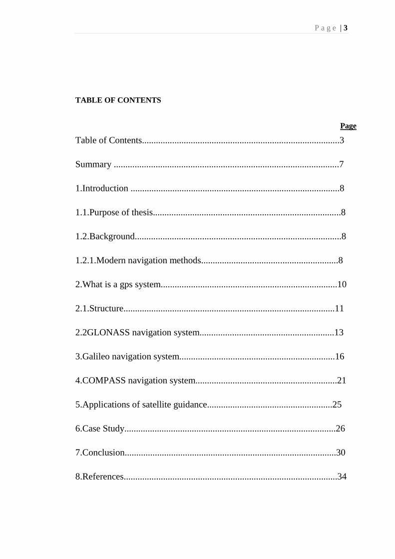
TABLE OF CONTENTS
Page
Table of Contents.....................................................................................3
Summary .................................................................................................7
1.Introduction ..........................................................................................8
1.1.Purpose of thesis.................................................................................8
1.2.Background.........................................................................................8
1.2.1.Modern navigation methods...........................................................8
2.What is a gps system............................................................................10
2.1.Structure...........................................................................................11
2.2GLONASS navigation system..........................................................13
3.Galileo navigation system...................................................................16
4.COMPASS navigation system.............................................................21
5.Applications of satellite guidance......................................................25
6.Case Study...........................................................................................26
7.Conclusion...........................................................................................30
8.References............................................................................................34

P a g e | 4

P a g e | 5
ABBREVIATIONS:
BPS: Bits per second
DOD : Department of defense
DOT: Department of transportation
EC: European Commission
EGNOS: European Geostationary Navigation Overlay Service
ESA: European Space Agency
EU: European union
GLONASS: Global Navigation Satellite System
GNSS: Global Navigation Satellite System
GOC: Galileo Operating Company
GPS: Global Positioning System
INS: Inertial Navigation Sysytems
MCS: Master Control Station
OS: Open Service
PNT: Position, navigation and timing
PPS: Precise Positioning Service
SPS: Standard Positioning Service
WAAS: Wide Area Augmentation System
FMS: Flight Management System
FANS: Future Air Navigation System

P a g e | 6
LIST OF TABLES
Page
Table 1.............................................................................................................................................24
Table 2............................................................................................................................. ...............25
P a g e | 7
LIST OF FIGURES
Page
Figure 1:Modern radar system.........................................................................10
Figure 2: GPS satellites....................................................................................11
Figure 3: Modern GPS satellite........................................................................13
Figure 4: GLONASS k ....................................................................................16
Figure 5: GIOVE A..........................................................................................21
Figure 6: Frequency allocation.........................................................................23
Figure 7: Applications of GNSS.......................................................................27
Figure 8: Boeing 747........................................................................................28
Figure 9: Hi bypass turbofan..........................................................................28
Figure 10: Flight deck of 747..........................................................................30
P a g e | 8
SATELLITE NAVIGATION AND ITS APPLICATIONS IN AVIONICS
SYSTEMS
SUMMARY:
What is navigation?
Navigation is the process of monitoring and controlling the movement of a craft or
vehicle from one place to another. it is a process of locating the navigators position
compared to known locations or patterns.
Basic concepts:
Latitude:
It is angular distance north or south of the equator. Latitude is usually expressed in
degrees ranging from 0 at the equator to 90 at the north and south poles. The latitude
of the north pole is 90N, and the latitude of the south pole is 90S. Historically ,
mariners calculated latitude in the northers hemisphere by sighting the nort star
Polaris with a sextant and sight reduction tables to take out error for height of eye
and atmospheric refraction. Generally, the height of Polaris in degrees of arc above
the horizon is the latitude of the observer.
Longitude:
Similar to latitude, the longitude of a place on the earth‟s surface is the angular
distance east or west of the prime meridian or Greenwich meridian. Longitude is
usually expressed in degrees ranging from 0 at the Greenwich meridian to 180 east
and west
References:.
URL <www.wikipedia/ satellite navigation>

P a g e | 9
1-INTRODUCTION
As aviation began to expand in the 1930s, the first radio navigation systems were
developed. Initially these were installed at the new growing US airports. One of the
most prominent was the „ radio range‟ system. It relied upon the transmission of
morse characters A(dot-dash) and N(dash-dot) in four evenly spaced orthogonal
directions. When flying the correct course, the A and N characters combined to
produce a humming noise which the pilot could detect in earphones. Deviation from
the desired course would result in either A or N characters becoming more dominant,
signifying the need for corrective action by turning left or right as appropriate.
1.1 Purpose of the Thesis
The main objectives of this study is to research on the satellite navigation systems
being used all around the world and future of this technology. To know about the
prospects of this technology in modern world and areas where it can be useful and
how it can be used in avionics systems and air traffic control.
1.2 Background
1.2.1Modern navigation methods:
Dead Reckoning:
Dead reckoning or DR , in which one advances a prior position using the ship‟s
course and speed. The new position is called a DR position. It is generally accepted
that only course and speed determine the DR position . Correcting the DR position
for leeway current effects , and steering error result in an estimated position or EP.
An inertial navigator develops an extremely accurate EP. The navigator uses dead
reckoning in many ways, such as:
1- To determine sunrise and sunset
2- To predict landfall, sighting lights and arrival times.
3- To evaluate the accuracy of electronic positioning information
4- To predict which celestial bodies will be available for future observation.
The most important use of dead reckoning is to project the position of the ship into
the immediate future and avoid hazards to navigation.

P a g e | 10
Piloting:
It involves navigating a vessel in restricted waters and fixing its position as precisely
as possible at frequent intervals. More so than in other phases of navigation, proper
preparation and attention to detail are important.
Celestial navigation:
Celestial navigation systems are based on observation of the positions of the sun,
moon, planets and navigational stars. Such systems are in use as well for terrestrial
navigating as for interstellar navigating.
Radio navigation:
A radio direction finder or rdf is a device for finding the direction to a radio source.
Due to radios ability to travel very long distances, it is a particularly good navigation
system for ships and aircraft that might be flying at a distance from land.
Radar navigation:
When a vessel is within radar range of land or special radar aids to navigation, the
navigator can take distances and angular bearings to charted objects and use thee to
establish arcs of position and lines of position on a chart. A fix consisting of only
radar information is called a radar fix.
Figure 1: Modern Radar System
References:
Allan g seabridge, and Ian moir,2003: Civil Avionics Sysytems, chapter6-
communications and navigation aids and chapter 8- navigation.

P a g e | 11
2-What is a gps system?
The global positioning system(gps) is a space based global navigation satellite
system(gnss) that provides location and time information in all weather,
anywhere on or near the earth, when there is an unobstructed line of sight to four
or more gps satellites. It is maintained by the united states government and is
freely accessible by anyone with a gps receiver.
Figure 2 GPS satellite
The GPS project was developed in 1973 to overcome the limitations of previous
navigation systems, integrating ideas from several predecessors including a number
ofclassified engineering design studies from the 1960s.
A GPS receiver calculates its position by precisely timing the signals sent by gps
satellites high above the earth. Each satellite continually transmits messages that
include
1. The time the message was transmitted
2. Precise orbital information
3. The general system health and rough orbits of all satellites
4. The receiver uses the messages it receives to determine the transit time of
each message and computes the distance to each satellite. These distances

P a g e | 12
along with the satellites locations are used with the possible aid of
trilateration.
5. Using messages received from a minimum of four visibe satellites, a gps
receiver is able to determine the times sent and then the satellite positions
corresponding to these times sent.
2.1 Structure:
The GPS consists of three major segments. These are the space segment, a control
segment(cs), a user segment(u.s). the space segment is composed of the orbiting gps
satellites, or space vehicles in gps parlance. The gps design originally called for 24
SVs. The orbits are centered on the earth, not rotating with the earth. The gpd space
segment is comprised of 24 satellites in a “walker constellation” at an altitude of
10,898 nautical miles, organised in six orbital planes equally spaced in right
ascension around the earth, with an inclination of 55 degrees. Walker constellations
are satellites configured in circular orbits with common altitudes and inclinations
that provide global coverage of the earth. The design of the GPS constellation
guarantees that at least five satellite with favourable satellite geometry are always in
view to users worldwide to meet accuracy requirements.
Four generations of satellite are:
1- Block 1- these satellites were prototypes to test the concept of navigation
from space.
2- Block 2- they were first operational series, added radiation hardening and a
14 day autonomous navigation message to increase survivability during war,
further emphasizing military utility, block 2 satellites also debuted selective
availability and anti spoofing. With selective availability the united states can
degrade gps accuracy to unauthorised users. Similarly, anti spoofing allows
the united states to deny high accuracy gps signals to real and potential
enemies through encryption and prevents enemies from transmitting false
gps- like signals intended to fool or corrupt gps receivers.
3- Block 2A- It extended the autonomous navigation message to 180 days,
providing slowly degrading data for six months in the event the ground-
control segment was destroyed.

P a g e | 13
4- Block 2R- It added additional radiation hardening and operational
redundancy, as well as a cross link ranging mode that enables IIR vehicles to
update their own navigation message without support from the ground for up
to 180 days.
The current constellation is comprised of block2/ 2A and IIR vehicles. Future
satellite generations include blocks IIR-M, IIF and GPS 3.
Figure 3 Modern gps satellite GPS 3
References:
Allan g seabridge, and Ian moir,2003: Civil Avionics Sysytems, chapter6-
communications and navigation aids and chapter 8- navigation.
2.2GLONASS Navigation System:
It is a radio-based navigation system operated by the Russian Space Forces. It is an
complement to the United States' Global Positioning System (GPS), the
Chinese Compass navigation system, and the planned Galileo positioning system of

P a g e | 14
the European Union (EU) and Indian Regional Navigational Satellite System of
India.
It is based on constellation of active satellites which continuously transmit
continuously transmit coded signals in two frequency bands to identify their position
and velocity in real time based on ranging measurements.
2.2.1 System Description
It is a global satellite navigation system that provide real time position and velocity
for military and civilian users. The satellites are located in middle circular orbit at
19,100 km altitude with a 64.8 degree inclination and a period of 11 hours and 15
minutes.
It is especially suited for usage in northern latitudes, where getting a GPS signal is
problematic. The constellation operates in three orbital planes, with 8 evenly spaced
satellites on each. A fully operational constellation with global coverage consists of
24 satellites, while 18 satellites are necessary for covering the territory of Russia. To
fix a position, the receiver must be in the range of at least four satellites, three of
which will be used to determine the user's location and the fourth to synchronise
clocks of the receiver and the three other spacecraft.
2.2.2 Signals
GLONASS satellites transmit two types of signal: a standard precision (SP) signal
and an high precision (HP) signal. The signals use DSSS encoding and binary phase-
shift keying (BPSK) modulation . Each satellite transmits on a different frequency
using a 15-channel (FDMA) technique spanning from 1602.0 MHz known as the
L1 band.
The HP signal is broadcast in phase quadrature with the SP signal, effectively
sharing the same carrier wave as the SP signal, but with a ten times higher bandwidth
than the SP signal.
The L2 signals use the same FDMA as the L1 band signals, but transmit straddling
1246 MHz with the center frequency determined by the equation 1246 MHz
+ n×0.4375 MHz, where n spans the same range as for L1..
2.2.3Satellites
The satellite designs have gone through numerous improvements and can be divided
into three generations:

P a g e | 15
1) The original GLONASS
2) GLONASS-M
3) GLONASS-K .
2.2.4First generation
The first generation of GLONASS satellites were all 3-axis stabilized vehicles,
generally weighing 1,250 kg and were equipped with a modest propulsion system to
permit relocation within the constellation. Over time they were upgraded to Block
IIa, IIb, and IIv vehicles, with each block containing evolutionary improvements.
Six Block IIa satellites were launched in 1985–1986 with improved time and
frequency standards over the prototypes, and increased frequency stability. These
spacecraft also demonstrated a 16-month average operational lifetime.
Block IIb spacecraft, with a 2-year design lifetimes, appeared in 1987, of which a
total of 12 were launched,.
Block IIv was the most prolific of the first generation. Used exclusively from 1988
to 2000, and continued to be included in launches through 2005, a total of 25
satellites were launched. The design life was three years, however numerous
spacecraft exceeded this, with one late model lasting 68 months.
2.2.5Second generation
The second generation of satellites, known as Glonass-M. They were developed
beginning in 1990 and first launched in 2003. These satellites possess a substantially
increased lifetime of seven years and weigh slightly more at 1,480 kg. They are
approximately 2.4 m (7 ft 10 in) in diameter and 3.7 m (12 ft) high, with a solar array
span of 7.2 m (24 ft) for an electrical power generation capability of 1600 watts at
launch.
The aft payload structure houses 12 primary antennas for L-band transmissions.
Laser corner-cube reflectors are also carried to aid in precise orbit determination and
geodetic research. A total of fourteen second generation satellites were launched
through the end of 2007.
2.2.6Third generation
P a g e | 16
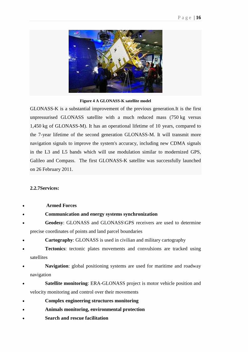
Figure 4 A GLONASS-K satellite model
GLONASS-K is a substantial improvement of the previous generation.It is the first
unpressurised GLONASS satellite with a much reduced mass (750 kg versus
1,450 kg of GLONASS-M). It has an operational lifetime of 10 years, compared to
the 7-year lifetime of the second generation GLONASS-M. It will transmit more
navigation signals to improve the system's accuracy, including new CDMA signals
in the L3 and L5 bands which will use modulation similar to modernized GPS,
Galileo and Compass. The first GLONASS-K satellite was successfully launched
on 26 February 2011.
2.2.7Services:
Armed Forces
Communication and energy systems synchronization
Geodesy: GLONASS and GLONASS\GPS receivers are used to determine
precise coordinates of points and land parcel boundaries
Cartography: GLONASS is used in civilian and military cartography
Tectonics: tectonic plates movements and convulsions are tracked using
satellites
Navigation: global positioning systems are used for maritime and roadway
navigation
Satellite monitoring: ERA-GLONASS project is motor vehicle position and
velocity monitoring and control over their movements
Complex engineering structures monitoring
Animals monitoring, environmental protection
Search and rescue facilitation

P a g e | 17
Personal trackers, "panic button"
References:
URL < www.spaceandtech/ glonass>
URL< www.wikipedia.com/ glonass>
3.Galileo Navigation System
Europe is moving closer to launch of its satellite navigation system Galileo.this will
lead to a fully civilian global satellite navigation system, with much improved
navigation services and a certified positioning services. It is an initiative of the
europen union in colloboration with the European Space Agency and European
industry.This is €20 billion project named after Italian Astronomer Galileo Galilei.
The navigation system is intended to provide measurements down to the meter
range including the height above sea. better positioning services at high latitudes
compared to GPS and GLONASS.A global Search and Rescue (SAR) function.
It is proposed as a Public Partnership formed between the European union, ESA and
a consortium of private companies.
Each satellite will be equipped with a transponder, which is able to transfer the
distress signals from the user's transmitter to the Rescue Co-ordination Centre, which
will then initiate the rescue operation. At the same time, the system will provide a
signal to the user, informing them that their situation has been detected.
3.1Galileo Experimental Satellites (GIOVE) Overview
The first experimental satellite, GIOVE-A, was launched on 28 December 2005. The
objective of this satellite is to characterize the critical technologies, which have
already been developed under ESA contracts.
The second experimental satellite, GIOVE-B, was launched on 27 April 2008. This
satellites closely resembles the envisioned Galileo satellites. Its objective is the
further characterize and test the critical technologies. In the case of GIOVE-B the
special highlight is the passive hydrogen maser (PHM). An ultra-stable clock which
holds a lot of promise for future GNSS systems in general and for Galileo in
particular
P a g e | 18
3.2Galileo Constellation Overview
Satellites consists of 24 satelites , with 21 used for transmitting signals and three for
in-orbit spares, deployed in three orbital planes.
The three orbital planes' ascending nodes are separated by 120° with each plane
containing eight equally spaced satellites. The orbits are roughly circular, with an
inclination of about 64.8°, and orbit the Earth at an altitude of 19,100 km, which
yields an orbital period of approximately 11 hours, 15 minutes.
References:
Scott W. Beidleman 2006: GPS versus Galileo chapter 1- introduction and chapter
2- GPS vs Galileo
3.3History:
In 1999, the different concepts of Galileo were compared and reduced to one by a
joint team of engineers from four countries( Germany, France, Italy and the United
Kingdom) . The first stage of the Galileo programme was agreed upon officially on
26 May 2003 by the European Union and the European Space Agency. The system is
intended primarily for civilian use. The European system was subject to shutdown
for military purposes in extreme circumstances. Otherwise it will be available at its
full precision to both civil and military users.
The European Commission had some difficulty getting money for the project's next
stage.The European Union and the European Space Agency agreed in March 2002 to
fund the project, pending a review in 2003. The starting cost for the period ending in
2005 is estimated at €1.1 billion. The required satellites (the planned number is 30)
will be launched throughout the period 2006–2010 and the system will be up and
running and under civilian control from 2010. The final cost is estimated at
€3 billion, including the infrastructure on Earth, which is to be constructed in the
years 2006 and 2007. The plan was for private companies and investors to invest at
least two-thirds of the cost of implementation, with the EU and ESA dividing the
remaining cost.

P a g e | 19
In June 2004, in a signed agreement with the United States, the European Union
agreed to switch to a modulation known as BOC(1,1) (Binary Offset Carrier 1.1)
allowing the coexistence of both GPS and Galileo, and the future combined use of
both systems. The European Union also agreed to address the "mutual concerns
related to the protection of allied and U.S. national security capabilities." The first
experimental satellite, GIOVE-A, was launched in 2005 and was followed by a
second test satellite, GIOVE-B, launched in 2008. The first four operational satellites
for navigation will be launched in 2011 and once this In-Orbit Validation (IOV)
phase wil be completed, additional satellites will be launched.
In November 2007, it was agreed to reallocate funds from the EU's agriculture and
administration budgets and to soften the tendering process in order to invite more EU
companies.
In April 2008, the EU transport ministers approved the Galileo Implementation
Regulation. This allowed the €3.4 bn to be released from the EU's agriculture and
administration budgets. This will allow the issuing of contracts to start construction
of the ground station and the satellites.
In November 2009, a ground station for Galileo was inaugurated
near Kourou (French Guiana).The launch of the first four in-orbit validation (IOV)
satellites is currently planned for the 2nd half of 2011, while the launch of full
operational capability (FOC) satellites is planned to start in late 2012.
3.4System description
3.4.1Galileo satellites
30 in-orbit spacecraft (including 3 spares)
orbital altitude: 23,222 km (MEO)
P a g e | 20
3 orbital planes, 56° inclination, ascending nodes separated by 120° longitude
(9 operational satellites and one active spare per orbital plane)
satellite lifetime: >12 years
satellite mass: 675 kg
satellite body dimensions: 2.7 m x 1.2 m x 1.1 m
span of solar arrays: 18.7 m
power of solar arrays: 1,500 W (end of life)
References:
URL <www.aat.com/ galileo-european satellite navigation system>
3.4.2Services
The Galileo system will have five main services:
Open Access Navigation: This will be 'free to air' and for use by the mass
market; Simple timing and positioning down to 1 metre.
Commercial Navigation (Encrypted): High accuracy to the centimetre;
Guaranteed service for which service providers will charge fees.
Safety Of Life Navigation: Open service; For applications where guaranteed
accuracy is essential; Integrity messages will warn of errors.
Public Regulated Navigation (Encrypted): Continuous availability even in
time of crisis; Government agencies will be main users.
Search And Rescue: System will pick up distress beacon locations; Feasible
to send feedback, confirming help is on its way.
3.5The concept
Each satellite will have two types of atomic clocks 4 in total (2 rubidium frequency
standards and 2 passive hydrogen masers). These clocks will provide an accurate
timing signal for a receiver to calculate the time that it takes the signal to reach the
target. This information is used to calculate the position of the receiver
by trilaterating the difference in received signals from multiple satellites.
3.6Satellite system

P a g e | 21
3.6.1: Galileo satellite test beds: GIOVE
Figure 5 GIOVE-A was successfully launched 28 December 2005.
In 2004 the Galileo System Test Bed Version 1 (GSTB-V1) project validated the on-
ground algorithms for Orbit Determination and Time Synchronisation (OD&TS).
This project, led by ESA and European Satellite Navigation Industries, has provided
industry with fundamental knowledge to develop the mission segment of the Galileo
positioning system. GIOVE-A is the first GIOVE (Galileo In-Orbit Validation
Element) test satellite. It was built by Surrey Satellite Technology Ltd (SSTL), and
successfully launched on 28 December 2005 by the European Space Agency and the
Galileo Joint. Operation of GIOVE-A ensured that Galileo meets the frequency-
filing allocation and reservation requirements for the International
Telecommunication Union (ITU), a process that was required to be complete by June
2006.
GIOVE-B, built by Astrium and Thales Alenia Space, has a more advanced payload
than GIOVE-A. It was successfully launched on 27 April 2008 at 22:16 UTC (4.16
a.m. (Baikonur time) aboard a Soyuz-FG/Fregat rocket provided by Starsem.
A third satellite, GIOVE-A2, was originally planned to be built by SSTL for launch
in the second half of 2008.
3.6.2 In-Orbit Validation (IOV) satellites
These testbed satellites will be followed by four IOV Galileo satellites that will be
much closer to the final Galileo satellite design. The launch of the first pair of
satellites is scheduled for the second half of 2011.
P a g e | 22
3.7 Full Operational Capability (FOC) satellites
On 7 January 2010, it was announced that the contract to build the first 14 FOC
satellites was awarded to OHB System and Surrey Satellite Technology Limited
(SSTL). Fourteen satellites will be built at a cost of 566M euros ($811M; £510M).
Arianespace will launch the satellites for a cost of 397M euros ($569M; £358M).
The first two satellites are scheduled to launch on 20 October 2011 from Guiana
Space Centre using the Soyuz launcher.[42]
The European Commission announced also that the contract of 85 million euros for
the System support covering industrial services required by ESA for integration and
validation of Galileo System was awarded to Thales Alenia Space. Thales Alenia
Space subcontract performances to Astrium Gmbh and security to Thales
Communications.
References:
URL< www.wikipedia.com/galileo>
4.Compass navigation system
The COMPASS system is a project by China to develop an independent
global satellite navigation system.
COMPASS is not an extension to the previously deployed Beidou-1, but a new
GNSS similar in principle to GPS, GLONASS, and Galileo.
The new system will be a constellation of 35 satellites, which include 5 geostationary
orbit(GEO) satellites and 30 medium Earth orbit (MEO) satellites. The ranging
signals are based on the CDMA principle and have complex structure typical
to Galileo or modernized GPS. There are two levels of positioning service: open and
restricted (military). The public service shall be available globally to general
users. The general designer of Compass navigation system is Sun Jiadong, who is
also the general designer of its predecessor, Beidou navigation system.
P a g e | 23
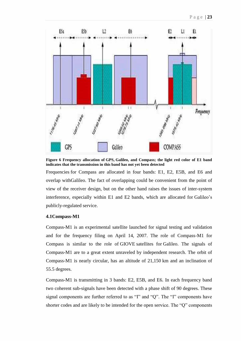
Figure 6 Frequency allocation of GPS, Galileo, and Compass; the light red color of E1 band
indicates that the transmission in this band has not yet been detected
Frequencies for Compass are allocated in four bands: E1, E2, E5B, and E6 and
overlap withGalileo. The fact of overlapping could be convenient from the point of
view of the receiver design, but on the other hand raises the issues of inter-system
interference, especially within E1 and E2 bands, which are allocated for Galileo‟s
publicly-regulated service.
4.1Compass-M1
Compass-M1 is an experimental satellite launched for signal testing and validation
and for the frequency filing on April 14, 2007. The role of Compass-M1 for
Compass is similar to the role of GIOVE satellites for Galileo. The signals of
Compass-M1 are to a great extent unraveled by independent research. The orbit of
Compass-M1 is nearly circular, has an altitude of 21,150 km and an inclination of
55.5 degrees.
Compass-M1 is transmitting in 3 bands: E2, E5B, and E6. In each frequency band
two coherent sub-signals have been detected with a phase shift of 90 degrees. These
signal components are further referred to as “I” and “Q”. The “I” components have
shorter codes and are likely to be intended for the open service. The “Q” components
P a g e | 24
have much longer codes, are more interference resistive, and are probably intended
for the restricted service.
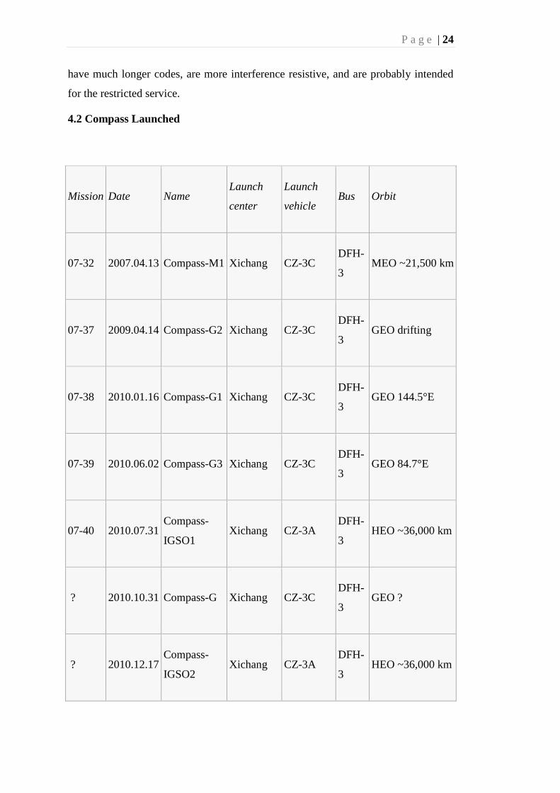
4.2 Compass Launched
Mission Date Name Launch
center
Launch
vehicle Bus Orbit
07-32 2007.04.13 Compass-M1 Xichang CZ-3C DFH-
3 MEO ~21,500 km
07-37 2009.04.14 Compass-G2 Xichang CZ-3C DFH-
3 GEO drifting
07-38 2010.01.16 Compass-G1 Xichang CZ-3C DFH-
3 GEO 144.5°E
07-39 2010.06.02 Compass-G3 Xichang CZ-3C DFH-
3 GEO 84.7°E
07-40 2010.07.31 Compass-
IGSO1 Xichang CZ-3A
DFH-
3 HEO ~36,000 km
? 2010.10.31 Compass-G Xichang CZ-3C DFH-
3 GEO ?
? 2010.12.17 Compass-
IGSO2 Xichang CZ-3A
DFH-
3 HEO ~36,000 km

P a g e | 25
? 2011.04.10 Compass-
IGSO3 Xichang CZ-3A
DFH-
3 HEO ~36,000 km
? 2011.07.27 Compass-
IGSO-4 Xichang CZ-3A
DFH-
3 HEO ~36,000 km
TABLE 1
References:
URL< www.spaceandtech/ compass>
URL< www.wikipedia.com/ compass>
4.3Comparison of systems
System Country Coding
Orbital
height &
period
Number
of
satellites
Frequency Status
GLONASS Russia FDMA/CDMA 19,100 km,
11.3h
24 (30
when
CDMA
signal
launches)
Around
1.602 GHz
(SP)
Around
1.246 GHz
(SP)
operational
with
restrictions,
CDMA in
preparation
Galileo European
Union CDMA
23,222 km,
14.1h
2 test bed
satellites
in orbit
22
operational
satellites
1.164-
1.215 GHz
(E5a and E5b)
1.215-
1.300 GHz
(E6)
1.559-
in
preparation
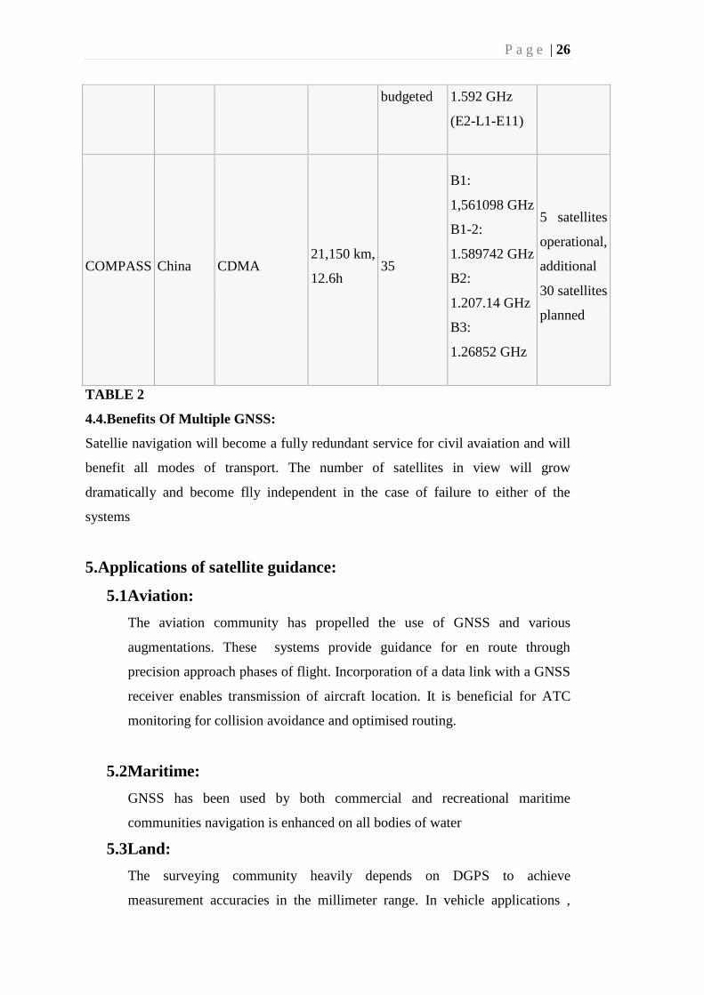
P a g e | 26
budgeted 1.592 GHz
(E2-L1-E11)
COMPASS China CDMA
21,150 km,
12.6h 35
B1:
1,561098 GHz
B1-2:
1.589742 GHz
B2:
1.207.14 GHz
B3:
1.26852 GHz
5 satellites
operational,
additional
30 satellites
planned
TABLE 2
4.4.Benefits Of Multiple GNSS:
Satellie navigation will become a fully redundant service for civil avaiation and will
benefit all modes of transport. The number of satellites in view will grow
dramatically and become flly independent in the case of failure to either of the
systems
5.Applications of satellite guidance:
5.1Aviation:
The aviation community has propelled the use of GNSS and various
augmentations. These systems provide guidance for en route through
precision approach phases of flight. Incorporation of a data link with a GNSS
receiver enables transmission of aircraft location. It is beneficial for ATC
monitoring for collision avoidance and optimised routing.
5.2Maritime:
GNSS has been used by both commercial and recreational maritime
communities navigation is enhanced on all bodies of water
5.3Land:
The surveying community heavily depends on DGPS to achieve
measurement accuracies in the millimeter range. In vehicle applications ,

P a g e | 27
GNSS is used for route guidance, tracking, and fleet management.
Combining a cellular phone or data link function with this system enables
vehicle tracing and/ or emergency messaging.
5.4Geographic Information Systems(GIS), Mapping, and
Agriculture:
Applications include utility and asset mapping and automated airborne mapping,
with remote sensing and photogromettry.
Figure 7 Applications of GNSS
References:
Angus P.Andrews and Lawrence R. Weill and Mohinder S.Grewal, 2001:
Global Positioning Systems, Inertial Navigation, and Integration ,
chapter 1- introduction, applications,
6.Case study:
6.1Abstract :
Future air navigation system is a concept that was developed by the civil aviation
organisation in partnership with boeing, airbus, Honeywell and others in the air
transport industry t allow more aircraft to safely and efficiently utilize a given
P a g e | 28
volume of airspace. It is now primarily used in the oceanic regions . in this case
study well we will look at how FANS is implemented in boeing 747.
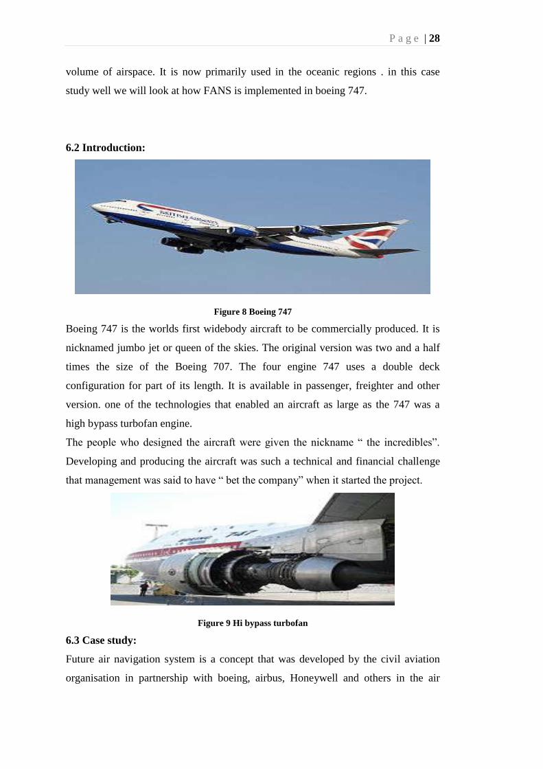
6.2 Introduction:
Figure 8 Boeing 747
Boeing 747 is the worlds first widebody aircraft to be commercially produced. It is
nicknamed jumbo jet or queen of the skies. The original version was two and a half
times the size of the Boeing 707. The four engine 747 uses a double deck
configuration for part of its length. It is available in passenger, freighter and other
version. one of the technologies that enabled an aircraft as large as the 747 was a
high bypass turbofan engine.
The people who designed the aircraft were given the nickname “ the incredibles”.
Developing and producing the aircraft was such a technical and financial challenge
that management was said to have “ bet the company” when it started the project.
Figure 9 Hi bypass turbofan
6.3 Case study:
Future air navigation system is a concept that was developed by the civil aviation
organisation in partnership with boeing, airbus, Honeywell and others in the air

P a g e | 29
transport industry to allow more aircraft to safely and efficiently utilize a given
volume of airspace.
It plays a pivotal role in supporting many of the evolving
CNS/ATM(Communication, navigation, surveillance/ Air Traffic Management)
strategies and mandates. The first fans were originally use with the boeing 747-400.
These b-747 FANS 1 equipped aircraft use global positioning system(GPS) satellites
and inertial reference systems(IRS) to fix their position and an on board Honeywell
Flight Management system(FMS) to manage the navigation solution and flow of
information. The position of the aircraft is sent to ATC. It enables ATC to create a
clear picture of air traffic. The FANS used in 747 consist of the following systems:
AFN- Air Traffic services(ATS) Facilities Notification: AFN contains the protocol
within the fms for the aircraft to log on to a ground facility.
ADS-A- Automatic Dependent Surveillance contains the software algorithms to
transmit the position of the aircraft every one to five minutes to an ATC listening
station.
CPDLC – Controller / Pilot Data Link communication: it is the data link software
algorithm that enables two way communication between the cockpit and ATC.
The pilot can see all the information through various displays such as:
1-Electronic flight bag(EFB)- It brings digital information management to the flight
deck ; substantially reduces the need for paper and improves communication
between flight crews, dispatchers, and air traffic management.
2-Vertical situation display(VSD)- It gives pilot a clear view of the airplanes current
and projected flight path. Graphical representation simplifies early detection of path
errors including missed glide slope intercepts.
3-Flight management computer(FMC)- the new FMC can store all data currently
available from the worldwide navigation database and is designed to accommodate
the anticipated increase in data.
4-Electronic checklist: they are easy to update, revise and distribute. Airlines can
customize the checklists to confirm their own procedures.
5-Airport moving map(AMM): It combines airport taxi charts and an electronic map
of airport taxiways, runways and gates providing precise navigational signals .
The flight deck includes a new flight management computer, integrated approach
navigation, global-positioning-landing-system autoland, navigation performance
P a g e | 30
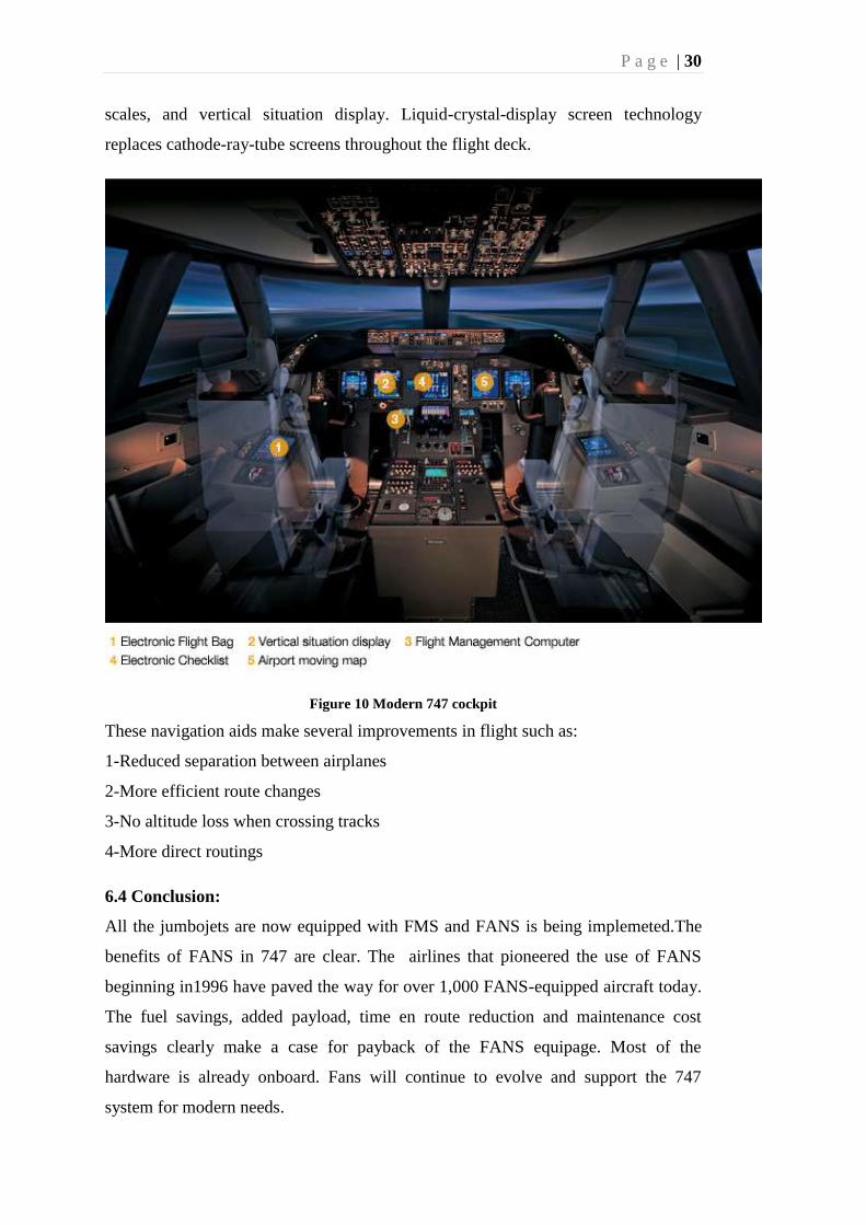
scales, and vertical situation display. Liquid-crystal-display screen technology
replaces cathode-ray-tube screens throughout the flight deck.
Figure 10 Modern 747 cockpit
These navigation aids make several improvements in flight such as:
1-Reduced separation between airplanes
2-More efficient route changes
3-No altitude loss when crossing tracks
4-More direct routings
6.4 Conclusion:
All the jumbojets are now equipped with FMS and FANS is being implemeted.The
benefits of FANS in 747 are clear. The airlines that pioneered the use of FANS
beginning in1996 have paved the way for over 1,000 FANS-equipped aircraft today.
The fuel savings, added payload, time en route reduction and maintenance cost
savings clearly make a case for payback of the FANS equipage. Most of the
hardware is already onboard. Fans will continue to evolve and support the 747
system for modern needs.

P a g e | 31
References:
URL< www.boeing747.com/ boeing-747-8-flight-deck>
URL< www.wikipedia.com/ boeing 747>
Allan g seabridge, and Ian moir,2003: Civil Avionics Sysytems, chapter6-
communications and navigation aids and chapter 8- navigation.
7.CONCLUSION:
7.1How Avionics systems are improved due to satellite guidance systems?
It is clear from the description of the aircraft navigation functions that navigation is a
complex task and becoming more so all the while. The future flight management
system will embrace dual computers and dual multifunction control and display
units(MCDUs).
. Dual INS/IRS.
. Dual navigation sensors: VOR/DME, DME/DME, etc.
. Dual GNSS sensors . usually GPS.
. Dual air data sensors.
. Dual inputs from on-board sensors relating to fuel on-board and time
These inputs are used by the FMS to perform the necessary navigation calculations
and provide information to the flight crew via a range of display units:
. Electronic flight instrument system (EFIS).
. Communications control system.
. Interface with the autopilot/flight director system to provide the flight crew
with
flight direction or automatic flight control in a number of predefined modes
P a g e | 32
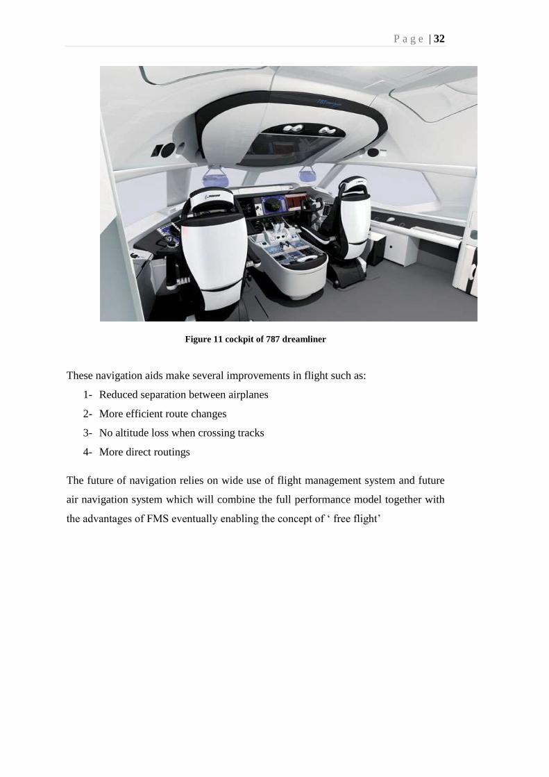
Figure 11 cockpit of 787 dreamliner
These navigation aids make several improvements in flight such as:
1- Reduced separation between airplanes
2- More efficient route changes
3- No altitude loss when crossing tracks
4- More direct routings
The future of navigation relies on wide use of flight management system and future
air navigation system which will combine the full performance model together with
the advantages of FMS eventually enabling the concept of „ free flight‟

P a g e | 33
33
REFERENCES
Allan g seabridge, and Ian moir,2003: Civil Avionics Sysytems, chapter6-
communications and navigation aids and chapter 8- navigation.
Angus P.Andrews and Lawrence R. Weill and Mohinder S.Grewal, 2001:
Global Positioning Systems, Inertial Navigation, and Integration ,
chapter 1- introduction, applications,
Scott W. Beidleman 2006: GPS versus Galileo chapter 1- introduction and chapter
2- GPS vs Galileo
URL <www.wikipedia/ satellite navigation>
URL < www.spaceandtech/ glonass>
URL <www.aat.com/ galileo-european satellite navigation system>
URL< www.wikipedia.com/ inertial navigation system>
URL< www.wikipedia.com/ glonass>
URL< www.wikipedia.com/ compass>
URL< www.wikipedia.com/ boeing 747>
URL< www.spaceandtech/ compass>
URL< www.boeing747.com/ boeing-747-8-flight-deck>

P a g e | 35
35
CURRICULUM VITAE
Candidate’s full name: Shikhar Sharma
Place and date of birth: Haldwani 13-10-1990
Permanent Address: Mahaveer ganj, near shiv mandir ,Haldwani, Nainital,
Uttarakhand-263139
Universities and
Colleges attended: U.P.E.S Dehradun
Publications: