Satellite M70 User’s Manual - Toshiba Canadaweb1.toshiba.ca/support/isg/manuals/psm70c/Satellite...
176
User’s Manual M70
Transcript of Satellite M70 User’s Manual - Toshiba Canadaweb1.toshiba.ca/support/isg/manuals/psm70c/Satellite...
User’s ManualM70
Copyright© 2005 by TOSHIBA Corporation. All rights reserved. Under copyright law, this manual cannot be reproduced in any form without the prior written permission of TOSHIBA. No patent liability is assumed, with respect to the use of the information contained herein.M70 Portable Personal Computer User’s Manual First edition September 2005Ownership and copyright of music, video computer programs, databases, etc. are protected by the copyright laws. These copyrighted materials may be copied for private use at home only. If, beyond the limitation above, you copy (including to transform data formats) or modify these materials, transfer them or distribute them via the Internet without approval of copyright owners, you may be subject to claims for compensation for damage and/or criminal penalities due to infringements of copyrights or personal rights. Please remember to observe the copyright laws when you use this product to copy the copyrighted works or perform other actions. Please note that you may infringe the owner’s rights protected by the copyright laws if you use the screen mode switching functions (e.g.Wide mode, Wide Zoom mode, etc.) of this product to display enlarged images/ video at coffee shops or hotels for the purposes of profits or providing these to the public.
DisclaimerThis manual has been validated and reviewed for accuracy. The instructions and descriptions it contains are accurate for the M70 Portable Personal Computers at the time of this manual’s production. However, succeeding computers and manuals are subject to change without notice. TOSHIBA assumes no liability for damages incurred directly or indirectly from errors, omissions or discrepancies between the computer and the manual.
TrademarksIBM is a registered trademark and IBM PC, OS/2, and PS/2 are trademarks of International Business Machines Corporation. Celeron, Intel, Intel SpeedStep, and Pentium are trademarks or registered trademarks of Intel Corporation.MS-DOS, Microsoft, Windows and DirectX are registered trademarks of Microsoft Corporation.Centronics is a registered trademark of Centronics Data Computer Corporation. Photo CD is a trademark of Eastman Kodak.Bluetooth is a trademark owned by its proprietor and used by TOSHIBA under license.iLINK is a trademark of Sony Corporation.
ii User’s Manual
TruSurround XT, WOW XT, SRS and symbol are trademarks of SRS Labs, Inc.TruSurround XT, WOW XT, TruBass, SRS 3D and FOCUS technologies are incorporated under license from SRS Labs, Inc.Other trademarks and registered trademarks not listed above may be used in this manual.
Macrovision License of NoticeThis product incorporates copyright protection technology that is protected by methods and claims of certain U.S. patents and other intellectual rights owned by Macrovision Corporation, and other rights owners. Use of this copyright protection technology must be authorized by Macrovision Corporation and is intended for home and other limited viewing uses only unless authorized by Macrovision Corporation. Reverse engineering of disassembly is prohibited.
Safety InstructionsUse the following safety guidelines to help protect yourself and your computer.
When Using Your ComputerDo not operate your portable computer for an extended period of time with the base resting directly on your body. With extended operation, heat can potentially build up in the base. Allowing sustained contact with the skin could cause discomfort or, eventually, a burn.■ Do not attempt to service the computer yourself. Always follow
installation instructions closely.■ Do not carry a battery in your pocket, purse, or other container where
metal objects (such as car keys) could short-circuit the battery terminals. The resulting excessive current follow can cause extremely high temperatures and may result in damage from burns.
■ Be sure that nothing rests on your AC adapter’s power cable and that the cable is not located where it can be tripped over or stepped on.
■ Place the AC adapter in a ventilated area, such as a desk top or on the floor, when you use it to run the computer or to charge the battery. Do not cover the AC adapter with papers or other items that will reduce cooling; also, do not use the AC adapter while it is inside a carrying case.
■ Use only the AC adapter and batteries that are approved for use with this computer. Use of another type of battery or AC adapter may risk fire or explosion.
User’s Manual iii
■ Before you connect the computer to a power source, ensure that the voltage rating of the AC adapter matches that of the available power source.115 V/60Hz in most of North and South America and some Far Eastern countries such as Taiwan.100 V/50Hz in eastern Japan and 100 V/60Hz in western Japan.230 V/50 Hz in most of Europe, the Middle East, and the Far East.
■ If you use an extension cable with your AC adapter, ensure that the total ampere rating of the products that are plugged into it do not exceed the ampere rating of the extension cable itself.
■ To help avoid the potential hazard of electric shock, do not connect or disconnect any cables or perform maintenance or reconfiguration of this product during an electrical storm.
■ When setting up the computer for work, place it on a level surface.■ Do not dispose of batteries in a fire. They may explode. Check with
local authorities for disposal instructions.■ When traveling, do not check the computer as baggage. You can put
your computer through an X-ray security machine, but never put your computer through a metal detector. If you have the computer checked by hand, be sure to have a charged battery available in case you are asked to turn on the computer.
■ When traveling with the hard drive removed from the computer, wrap the drive in a non-conducting material, such as cloth or paper. If you have the drive checked by hand, be ready to install the drive in the computer. Your can put the hard drive through an X-ray security machine, but never put it through a metal detector.
■ When traveling, do not place the computer in overhead storage compartments where it could slide around. Do not drop your computer or subject it to other mechanical shocks.
■ Protect your computer, battery, and hard drive from environmental hazards such as dirt, dust, food, liquids, temperature extremes, and overexposure to sunlight.
■ When you move your computer between environments with very different temperature and/or humidity ranges, condensation may form on or within the computer. To avoid damaging the computer, allow sufficient time for the moisture to evaporate before using the computer.
■ When you disconnect a cable, pull on its connector or on its strain relief loop, not on the cable itself. As you pull out the connector, keep it evenly aligned to avoid bending any connector pins. Also, before you connect a cable make sure both connectors are correctly oriented and aligned.
■ Before you clean your computer, turn if off, unplug it from its power source, and remove the battery.
■ Handle components with care. Hold a component such as a memory module by its edges, not its pins.
iv User’s Manual
■ Do not use this product near water, for example, near a bathtub, washing bowl, kitchen sink or laundry tub, in a wet basement or near a swimming pool.
■ Avoid using a telephone (other than a cordless type) during an electrical storm. There may be a remote risk of electric shock from lightning.
■ Do not use the telephone to report a gas leak in the vicinity of the leak.■ Use only the power cord indicated in this manual.■ Replace only with the same or equivalent type battery recommended by
the manufacturer.■ Dispose of used batteries according to the manufacturer’s instructions.■ To reduce the risk of fire, use only No. 26 AWG or larger
telecommunication line cord.
TOSHIBA assumes no liability for any damage in such case.
EU Declaration of Conformity
When using telephone equipment in conjunction with your computer, basic safety precautions should always be followed to reduce the risk of fire, electric shock and injury to persons, including the following:
Use only the battery pack that came with the computer or an optional battery pack. Use of the wrong battery could damage your computer.
This product is labelled with the CE Mark in accordance with the related European Directives, notably Electromagnetic Compatibility Directive 89/336/EEC for the notebook and the electronic accessories including the supplied power adapter, the Radio Equipment and Telecommunications Terminal Equipment Directive 99/5/EC in case of implemented telecommunication accessories and the Low Voltage Directive 73/23/EEC for the supplied power adapter. CE Marking is the responsibility of TOSHIBA EUROPE GmbH, Hammfelddamm 8, 41460 Neuss, Germany, phone +49-(0)-2131-158-01.For a copy of the related CE Declaration of Conformity please refer to the following website: http://epps.toshiba-teg.comThis product and the supplied accessories are designed to observe the related EMC (Electromagnetic Compatibility) and safety standards. However, TOSHIBA cannot guarantee that this product still observes these EMC standards if accessories or cables not manufactured / distributed by TOSHIBA are connected or implemented. To avoid EMC problems in general, the following advice should be observed:
■ Only CE marked accessories should be connected / implemented.■ Only best shielded cables should be connected.
User’s Manual v
Following information is only for EU-member states:The symbol indicates that this product may not be treated as household waste. Please ensure this product is properly disposed as inappropriate waste handling of this product may cause potential hazards to the environment and human health. For more detailed information about recycling of this product, please contact your local city office, your household waste disposal service or the shop where you purchased the product.
Optical Disc Drive Safety Instruction
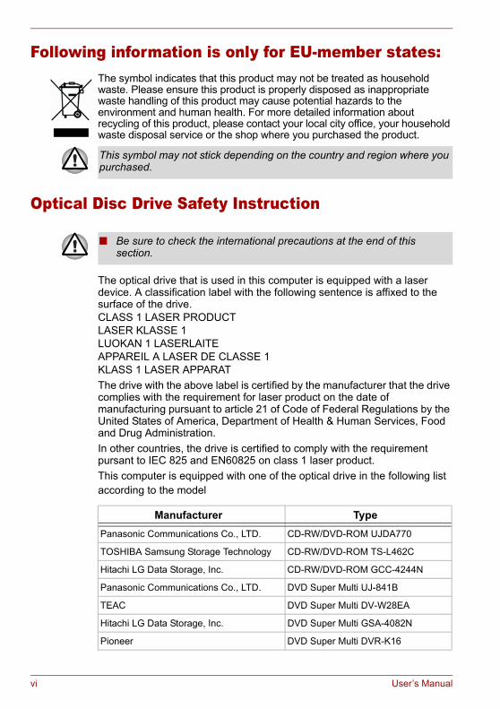
The optical drive that is used in this computer is equipped with a laser device. A classification label with the following sentence is affixed to the surface of the drive.CLASS 1 LASER PRODUCTLASER KLASSE 1LUOKAN 1 LASERLAITEAPPAREIL A LASER DE CLASSE 1KLASS 1 LASER APPARATThe drive with the above label is certified by the manufacturer that the drive complies with the requirement for laser product on the date of manufacturing pursuant to article 21 of Code of Federal Regulations by the United States of America, Department of Health & Human Services, Food and Drug Administration.In other countries, the drive is certified to comply with the requirement pursant to IEC 825 and EN60825 on class 1 laser product.This computer is equipped with one of the optical drive in the following list according to the model
This symbol may not stick depending on the country and region where you purchased.
■ Be sure to check the international precautions at the end of this section.
Manufacturer TypePanasonic Communications Co., LTD. CD-RW/DVD-ROM UJDA770
TOSHIBA Samsung Storage Technology CD-RW/DVD-ROM TS-L462C
Hitachi LG Data Storage, Inc. CD-RW/DVD-ROM GCC-4244N
Panasonic Communications Co., LTD. DVD Super Multi UJ-841B
TEAC DVD Super Multi DV-W28EA
Hitachi LG Data Storage, Inc. DVD Super Multi GSA-4082N
Pioneer DVD Super Multi DVR-K16
vi User’s Manual
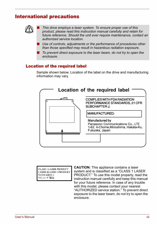
International precautions
Location of the required labelSample shown below. Location of the label on the drive and manufacturing information may vary.
■ This drive employs a laser system. To ensure proper use of this product, please read this instruction manual carefully and retain for future reference. Should the unit ever require maintenance, contact an authorized service location.
■ Use of controls, adjustments or the performance of procedures other than those specified may result in hazardous radiation exposure.
■ To prevent direct exposure to the laser beam, do not try to open the enclosure.
CAUTION: This appliance contains a laser system and is classified as a “CLASS 1 LASER PRODUCT.” To use this model properly, read the instruction manual carefully and keep this manual for your future reference. In case of any trouble with this model, please contact your nearest “AUTHORIZED service station.” To prevent direct exposure to the laser beam, do not try to open the enclosure.
User’s Manual vii
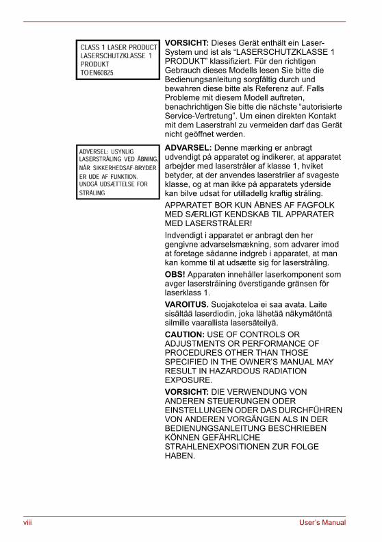
VORSICHT: Dieses Gerät enthält ein Laser- System und ist als “LASERSCHUTZKLASSE 1 PRODUKT” klassifiziert. Für den richtigen Gebrauch dieses Modells lesen Sie bitte die Bedienungsanleitung sorgfältig durch und bewahren diese bitte als Referenz auf. Falls Probleme mit diesem Modell auftreten, benachrichtigen Sie bitte die nächste “autorisierte Service-Vertretung”. Um einen direkten Kontakt mit dem Laserstrahl zu vermeiden darf das Gerät nicht geöffnet werden.
ADVARSEL: Denne mærking er anbragt udvendigt på apparatet og indikerer, at apparatet arbejder med laserstråler af klasse 1, hviket betyder, at der anvendes laserstrlier af svageste klasse, og at man ikke på apparatets yderside kan bilve udsat for utilladellg kraftig stråling.APPARATET BOR KUN ÅBNES AF FAGFOLK MED SÆRLIGT KENDSKAB TIL APPARATER MED LASERSTRÅLER!Indvendigt i apparatet er anbragt den her gengivne advarselsmækning, som advarer imod at foretage sådanne indgreb i apparatet, at man kan komme til at udsætte sig for laserstråling.OBS! Apparaten innehåller laserkomponent som avger laserstråining överstigande gränsen för laserklass 1.VAROITUS. Suojakoteloa ei saa avata. Laite sisältää laserdiodin, joka lähetää näkymätöntä silmille vaarallista lasersäteilyä.CAUTION: USE OF CONTROLS OR ADJUSTMENTS OR PERFORMANCE OF PROCEDURES OTHER THAN THOSE SPECIFIED IN THE OWNER’S MANUAL MAY RESULT IN HAZARDOUS RADIATION EXPOSURE.VORSICHT: DIE VERWENDUNG VON ANDEREN STEUERUNGEN ODER EINSTELLUNGEN ODER DAS DURCHFÜHREN VON ANDEREN VORGÄNGEN ALS IN DER BEDIENUNGSANLEITUNG BESCHRIEBEN KÖNNEN GEFÄHRLICHE STRAHLENEXPOSITIONEN ZUR FOLGE HABEN.
viii User’s Manual
Modem warning noticeConformity Statement
The equipment has been approved to [Commission Decision “CTR21”] for pan- European single terminal connection to the Public Switched Telephone Network (PSTN).However, due to differences between the individual PSTNs provided in different countries/regions the approval does not, of itself, give an unconditional assurance of successful operation on every PSTN network termination point.In the event of problems, you should contact your equipment supplier in the first instance.
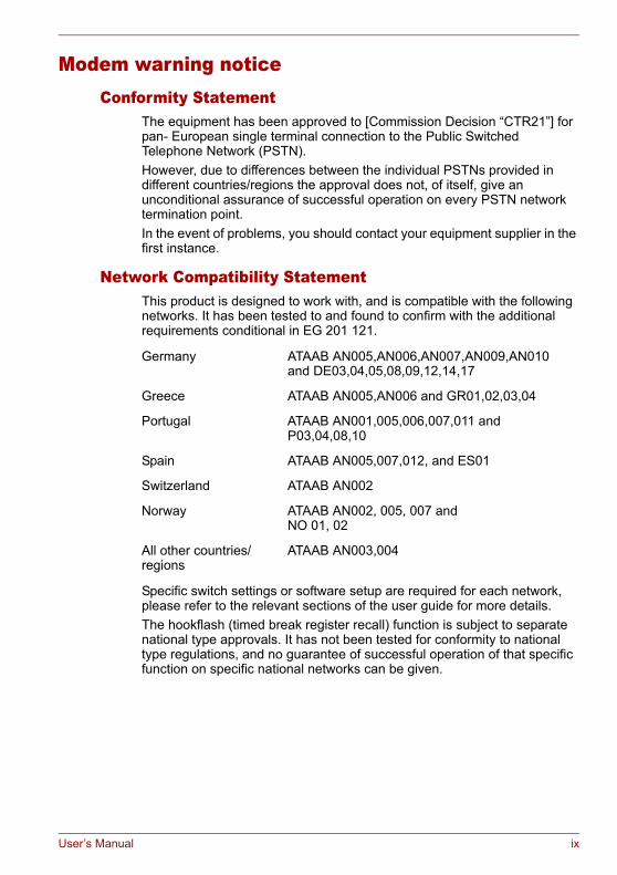
Network Compatibility StatementThis product is designed to work with, and is compatible with the following networks. It has been tested to and found to confirm with the additional requirements conditional in EG 201 121.
Specific switch settings or software setup are required for each network, please refer to the relevant sections of the user guide for more details.The hookflash (timed break register recall) function is subject to separate national type approvals. It has not been tested for conformity to national type regulations, and no guarantee of successful operation of that specific function on specific national networks can be given.
Germany ATAAB AN005,AN006,AN007,AN009,AN010 and DE03,04,05,08,09,12,14,17
Greece ATAAB AN005,AN006 and GR01,02,03,04
Portugal ATAAB AN001,005,006,007,011 and P03,04,08,10
Spain ATAAB AN005,007,012, and ES01
Switzerland ATAAB AN002
Norway ATAAB AN002, 005, 007 andNO 01, 02
All other countries/regions
ATAAB AN003,004
User’s Manual ix

Important NoticeCopyrighted works including, but not limited to music, video, computer program, databases are protected by copyright laws. Unless specifically permitted under applicable copyright laws, you cannot copy, modify, assign, transmit or otherwise dispose of any copyrighted work with the consent of the owner of the copyright.Please take notice that unauthorized copying, modification, assignment, transmission and disposition may be subject to claims for damages and penalties.
x User’s Manual
General Precautions
TOSHIBA computers are designed to optimize safety, minimize strain and withstand the rigors of portability. However, certain precautions should be observed to further reduce the risk of personal injury or damage to the computer.Be certain to read the general precautions below and to note the cautions included in the text of the manual.
Stress injuryCarefully read the Instruction Manual for Safety and Comfort. It contains information on prevention of stress injuries to your hands and wrists that can be caused by extensive keyboard use. Chapter 3, Getting Started, also includes information on work space design, posture and lighting that can help reduce physical stress.
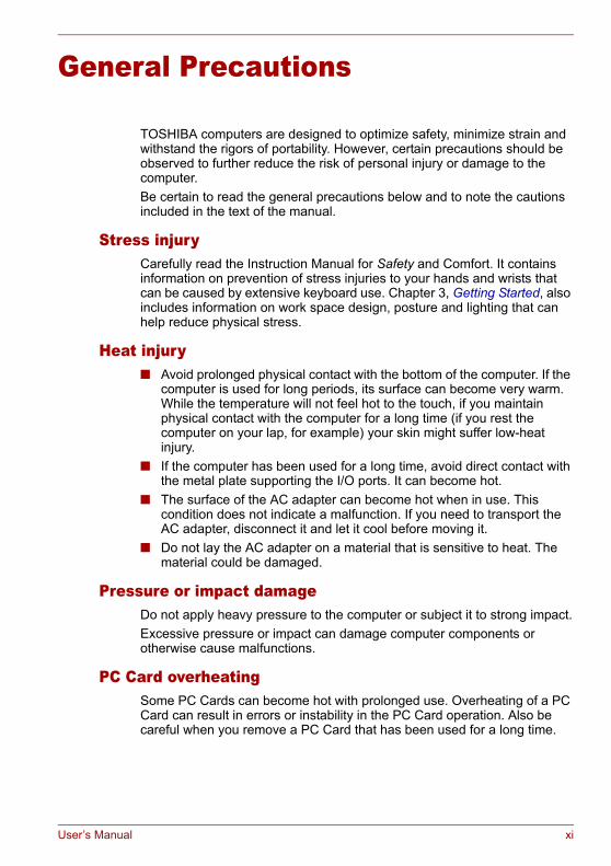
Heat injury■ Avoid prolonged physical contact with the bottom of the computer. If the
computer is used for long periods, its surface can become very warm. While the temperature will not feel hot to the touch, if you maintain physical contact with the computer for a long time (if you rest the computer on your lap, for example) your skin might suffer low-heat injury.
■ If the computer has been used for a long time, avoid direct contact with the metal plate supporting the I/O ports. It can become hot.
■ The surface of the AC adapter can become hot when in use. This condition does not indicate a malfunction. If you need to transport the AC adapter, disconnect it and let it cool before moving it.
■ Do not lay the AC adapter on a material that is sensitive to heat. The material could be damaged.
Pressure or impact damageDo not apply heavy pressure to the computer or subject it to strong impact.Excessive pressure or impact can damage computer components or otherwise cause malfunctions.
PC Card overheatingSome PC Cards can become hot with prolonged use. Overheating of a PC Card can result in errors or instability in the PC Card operation. Also be careful when you remove a PC Card that has been used for a long time.
User’s Manual xi
Mobile phoneUse of mobile phones can interfere with the audio system. Computer operation is not impaired but it is recommended that a distance of 30 cm be maintained between the computer and a mobile phone in use.
LCDOver a period of time, and depending on the usage of the computer, the brightness of the LCD screen will deteriorate. This is an intrinsic characteristic of LCD technology. Maximum brightness is only available when operating in AC power mode. The screen will dim when the computer is operated on battery power and you may not be able to increase the brightness of the screen.
Central Processing Unit (“CPU”) Performance Disclaimer:CPU performance in your computer product may vary from specifications under the following conditions:■ use of certain external peripheral products■ use of battery power instead of AC power■ use of certain multimedia, computer generated graphics or video
applications ■ use of standard telephone lines or low speed network connections■ use of complex modeling software, such as high end computer aided
design applications■ use of several applications or functionalities simultaneously■ use of computer in areas with low air pressure (high altitude >
1,000 meters or > 3,280 feet above sea level)■ use of computer at temperatures outside the range of 5 ºC to 30 ºC
(41ºF to 86 ºF) or > 25 ºC (77 ºF) at high altitude (all temperature references are approximate and may vary depending on the specific computer model).
CPU performance may also vary from specifications due to design configuration. Under some conditions, your computer product may automatically shut-down. This is a normal protective feature designed to reduce the risk of lost data or damage to the product when used outside recommended conditions. To avoid risk of lost data, always make back-up copies of data by periodically storing it on an external storage medium. For optimum performance, use your computer product only under recommended conditions. Read additional restrictions under “Environmental Conditions” in your product Resource Guide. Contact Toshiba Technical Service and Support for more information.
xii User’s Manual

Graphics Processing Unit (“GPU”) Performance Disclaimer:The graphics processing unit (“GPU”) performance may vary depending on product model, design configuration, applications, power management settings and features utilized. GPU performance is only optimized when operating in AC power mode and may decrease considerably when operating in battery power mode.
Main Memory DisclaimerThe graphics system in your computer may use part of the main system memory for graphics performance and therefore reduce the amount of system memory available for other computing activities. The amount of system memory allocated to support graphics may vary depending on the graphics system, applications utilized, system memory size and other factors.
Copy ProtectionCopy protection technology included in certain media may prevent or limit recording or viewing of the media.
Hard Disk Drive Capacity1 Gigabyte (GB) means 1000 x 1000 x 1000 = 1,000,000,000 bytes using powers of 10. The computer operating system, however, reports storage capacity using powers of 2 for the definition of 1 GB = 1024 x 1024 x 1024 = 1,073,741,824 bytes, and therefore may show less storage capacity. Available storage capacity will also be less if the product includes one or more pre-installed operating systems, such as Microsoft Windows®, and/or any pre-installed software applications or media content. Actual formatted capacity may vary.
Non-applicable IconsCertain notebook chassis are designed to accommodate all possible configurations for an entire product series. Your selected model may not have all the features and specifications corresponding to all of the icons or switches shown on the notebook chassis, unless you have selected all those features.
Wireless LAN/AtherosThe transmission speed over the wireless LAN and the distance over which wireless LAN can reach may vary depending on surrounding electromagnetic environment, obstacles, access point design and configuration, and client design and software/hardware configurations. The actual transmission speed will be lower than the theoretical maximum speed.
SRSSRS TruSurround XT is available in the Microsoft Windows® operating system only.
User’s Manual xiii
ImagesAll images are simulated for purposes of illustration.
Express Media PlayerThe Express Media Player is not a Windows® based application. Battery life will be less than when using similar applications in the Windows operating system.
LCD Brightness and Eye StrainYour LCD display has a brightness approaching that of a TV device. We recommend that you adjust the brightness of your LCD to a comfortable level to prevent possible strain on your eyes.
Working environmentThis product was designed to fulfill the EMC (Electromagnetic Compatibility) requirements for “residential, commercial and light industry environments”.The following environment is not approved:■ Industrial Environments (e.g. environments where a with a mains
voltage of 380V threephase is being used).In the following environments the use of this product can be restricted:■ Medical Environments: This product is not certified as a medical
product according to the Medical Product Directive 93/42/EEC, but can be used in office areas where the use is not restricted. Please disable the wireless LAN or Bluetooth hardware in such areas as long this feature is not official supported by the operator of the related medical facility.
■ Vehicle Environments: Please read operator’s manual of the vehicle manufacturer for further restrictions of use.
■ Aircraft Environments: Please following the advices of the flight personnel regarding restrictions of use.
Any consequences resulting from the use of this product in working environments that are not approved or the use is restricted are not the responsibility of Toshiba Corporation. The consequences of the use of this product in those working environments may be:■ Interference with other devices or machines in the nearby surrounding
area■ Malfunction of, or data loss from, this product caused by disturbances
generated by other devices or machines in the nearby surrounding areaFurthermore, for general safety reasons, the use of this product in environments with explosive atmospheres is not permitted.
xiv User’s Manual
Network connection (Class A warning)If this product has networking capabilities and will be connected to a network, Class A radiation limits will be observed (in accordance with technical conventions). This means that if the product will be used in a domestic environment, other devices in the near surrounding area may suffer interference. Consequently, please do not use this product in such environments (for example a living room), otherwise you could be held responsible for any ensuing interference.
Information on the secure writing to optical disc mediaEven if your software gives no indication that any problems have occurred, you should always check to ensure that information has been successfully stored on recordable optical media (CD-R, CD-RW and so forth).
Wireless LAN and your HealthWireless LAN products, like other radio devices, emit radio frequency electromagnetic energy. The level of energy emitted by Wireless LAN devices however is far less than the electromagnetic energy emitted by other wireless devices such as mobile phones.Because Wireless LAN products operate within the guidelines found in radio frequency safety standards and recommendations, TOSHIBA believes Wireless LAN is safe for use by consumers. These standards and recommendations reflect the consensus of the scientific community and result from deliberations of panels and committees of scientists who continually review and interpret the extensive research literature.In some situations or environments, the use of Wireless LAN may be restricted by the proprietor of the building or responsible representatives of the organisation. These situations may for example include:■ Using the Wireless LAN equipment on board of aeroplanes■ In any other environment where the risk of interference to other devices
or services is perceived or identified as harmful.If you are uncertain of the policy that applies on the use of wireless devices in a specific organisation or environment (e.g. airports), you are encouraged to ask for authorisation to use the Wireless LAN device prior to turning on the equipment.
User’s Manual xv

Safety Instruction for Wireless ProductsIf your computer has a wireless function, all safety instructions must be read carefully and must be fully understood, before you attempt to use it. This manual contains the safety instructions that must be observed in order to avoid potential hazards that could result in personal injuries or could damage your wireless products.
Limitation of LiabilityFor damage occurring due to an earthquake or thunder, fire beyond our responsibility, action by third party, other accident, intentional or accidental mistakes by a user, misuse or use under abnormal conditions, we do not take any responsibility.For incidental damage (loss of business profit, business interruption, etc.) occurring due to use or disability of the product, we do not take any responsibility.For damage occurring due to non observance of the contents described in the instruction manual, we do not take any responsibility.For damage occurring due to erroneous operation or hang up caused by use in combination with products not related to our company, we do not take any responsibility.
Usage RestrictionsDo not use the Wireless Products for controlling the following equipment:■ Equipment directly linked with human life corresponding to the
following.■ Medical equipment such as life support systems, equipment used in
operations, etc.■ Exhaust systems for gases such as poisonous gas etc. and exhaust
systems for smoke.■ Equipment that must be set up in compliance with various laws such
as the Fire Services Act, the Construction Standard Act, etc.■ Equipment corresponding to that mentioned above.
■ Equipment linked with human safety or having a serious influence on the safe maintenance of public function, etc., because it is not designed or manufactured for this type of use.■ Traffic control equipment for air, railroad, road, marine transport, etc.■ Equipment used in atomic power plants etc.■ Equipment corresponding to that mentioned above.
xvi User’s Manual
Warning
Note
Turn OFF the Wireless Communication switch of wireless products in a congested place, such as a crowded commuter train.Keep this product away from a cardiac pacemaker at least 22cm.Radio waves can potentially affect cardiac pacemaker operation, thereby causing respiratory troubles.Turn OFF the Wireless communication switch inside a medical facility or near medical electric equipment. Do not bring medical electric equipment close to the product.Radio waves can potentially affect medical electric equipment, thereby causing an accident due to malfunction.Turn OFF the Wireless communication switch near an automatic door, fire alarm or other automatic control equipment.Radio waves can potentially affect automatic control equipment, thereby causing an accident due to malfunction.Do not turn ON the Wireless communication switch in aircraft or in places that generate or can generate radio interference.Radio waves can potentially affect equipment, such as that used on-board aircraft, causing an accident due to malfunction.You should monitor possible radio interference or other issues that may arise with other equipment while the product is used. If any effect is noted, turn OFF the Wireless communication switch.Otherwise, radio waves can potentially affect other equipment, thereby causing an accident due to malfunction.When using the product in a car, check with the automobile dealer if the car has an adequate electromagnetic compatibility (EMC).Radio waves of the product can potentially hamper safe driving.Depending on car model, the product can rarely affect car electronic equipment if it is used in a car.
Do not use this product in the following places:Near a microwave oven or other environment which generates a magnetic field.Near any place or equipment that generates static electricity or radio interference.Depending on the environment, in a place where radio waves cannot reach the product.
User’s Manual xvii

xviii User’s Manual
Table of Contents
General Precautions
PrefaceChapter 1 Introduction
Features. . . . . . . . . . . . . . . . . . . . . . . . . . . . . . . . . . . . . . . . . . . . . . . . . 1-3Special features . . . . . . . . . . . . . . . . . . . . . . . . . . . . . . . . . . . . . . . . . 1-10Utilities. . . . . . . . . . . . . . . . . . . . . . . . . . . . . . . . . . . . . . . . . . . . . . . . . 1-11Options . . . . . . . . . . . . . . . . . . . . . . . . . . . . . . . . . . . . . . . . . . . . . . . . 1-14
Chapter 2 The Grand TourFront with the display closed . . . . . . . . . . . . . . . . . . . . . . . . . . . . . . . 2-1Right side . . . . . . . . . . . . . . . . . . . . . . . . . . . . . . . . . . . . . . . . . . . . . . . 2-3Left side . . . . . . . . . . . . . . . . . . . . . . . . . . . . . . . . . . . . . . . . . . . . . . . . . 2-4Back side. . . . . . . . . . . . . . . . . . . . . . . . . . . . . . . . . . . . . . . . . . . . . . . . 2-5Underside . . . . . . . . . . . . . . . . . . . . . . . . . . . . . . . . . . . . . . . . . . . . . . . 2-6Front with the display open. . . . . . . . . . . . . . . . . . . . . . . . . . . . . . . . . 2-7Keyboard Indicators. . . . . . . . . . . . . . . . . . . . . . . . . . . . . . . . . . . . . . . 2-9Optical Disc drive . . . . . . . . . . . . . . . . . . . . . . . . . . . . . . . . . . . . . . . . 2-10AC adapter . . . . . . . . . . . . . . . . . . . . . . . . . . . . . . . . . . . . . . . . . . . . . 2-12
Chapter 3 Getting StartedSetting up your work space. . . . . . . . . . . . . . . . . . . . . . . . . . . . . . . . . 3-1Connecting the AC adapter . . . . . . . . . . . . . . . . . . . . . . . . . . . . . . . . . 3-5Opening the display . . . . . . . . . . . . . . . . . . . . . . . . . . . . . . . . . . . . . . . 3-6Turning on the power . . . . . . . . . . . . . . . . . . . . . . . . . . . . . . . . . . . . . . 3-6Starting up for the first time . . . . . . . . . . . . . . . . . . . . . . . . . . . . . . . . 3-7Turning off the power . . . . . . . . . . . . . . . . . . . . . . . . . . . . . . . . . . . . . . 3-7Restarting the computer . . . . . . . . . . . . . . . . . . . . . . . . . . . . . . . . . . 3-11Restoring the preinstalled software . . . . . . . . . . . . . . . . . . . . . . . . . 3-11
User’s Manual xix
Chapter 4 Operating BasicsUsing the Touch Pad . . . . . . . . . . . . . . . . . . . . . . . . . . . . . . . . . . . . . . .4-1Using the internal modem . . . . . . . . . . . . . . . . . . . . . . . . . . . . . . . . . . .4-2LAN . . . . . . . . . . . . . . . . . . . . . . . . . . . . . . . . . . . . . . . . . . . . . . . . . . . . .4-6Wireless LAN . . . . . . . . . . . . . . . . . . . . . . . . . . . . . . . . . . . . . . . . . . . . .4-7Using optical disc drives . . . . . . . . . . . . . . . . . . . . . . . . . . . . . . . . . . . .4-8Express Media Player . . . . . . . . . . . . . . . . . . . . . . . . . . . . . . . . . . . . .4-13Writing CDs on a CD-RW/DVD-ROM drive . . . . . . . . . . . . . . . . . . . . .4-18Writing CDs/DVDs on a DVD Super Multi drive supporting ±R Double Layer . . . . . . . . . . . . . . . . . . . . . . . . . . . . . . . .4-20RecordNow! Basic for TOSHIBA. . . . . . . . . . . . . . . . . . . . . . . . . . . . .4-24DLA for TOSHIBA. . . . . . . . . . . . . . . . . . . . . . . . . . . . . . . . . . . . . . . . .4-25When Using WinDVD Creator 2 Platinum . . . . . . . . . . . . . . . . . . . . .4-26Media Care . . . . . . . . . . . . . . . . . . . . . . . . . . . . . . . . . . . . . . . . . . . . . .4-29Disks . . . . . . . . . . . . . . . . . . . . . . . . . . . . . . . . . . . . . . . . . . . . . . . . . . .4-29TV-Out . . . . . . . . . . . . . . . . . . . . . . . . . . . . . . . . . . . . . . . . . . . . . . . . . .4-30Setting up more than one display. . . . . . . . . . . . . . . . . . . . . . . . . . . .4-30Cleaning the computer . . . . . . . . . . . . . . . . . . . . . . . . . . . . . . . . . . . .4-31Moving the computer . . . . . . . . . . . . . . . . . . . . . . . . . . . . . . . . . . . . . .4-31
Chapter 5 The KeyboardTypewriter keys . . . . . . . . . . . . . . . . . . . . . . . . . . . . . . . . . . . . . . . . . . .5-1F1 ... F12 function keys . . . . . . . . . . . . . . . . . . . . . . . . . . . . . . . . . . . . .5-2Soft keys: Fn key combinations . . . . . . . . . . . . . . . . . . . . . . . . . . . . . .5-2Hotkeys . . . . . . . . . . . . . . . . . . . . . . . . . . . . . . . . . . . . . . . . . . . . . . . . . .5-3Windows special keys . . . . . . . . . . . . . . . . . . . . . . . . . . . . . . . . . . . . . .5-4Keypad overlay. . . . . . . . . . . . . . . . . . . . . . . . . . . . . . . . . . . . . . . . . . . .5-5Generating ASCII characters. . . . . . . . . . . . . . . . . . . . . . . . . . . . . . . . .5-6
Chapter 6 Power and Power-Up ModesPower conditions . . . . . . . . . . . . . . . . . . . . . . . . . . . . . . . . . . . . . . . . . .6-1Power indicators . . . . . . . . . . . . . . . . . . . . . . . . . . . . . . . . . . . . . . . . . .6-2Battery types. . . . . . . . . . . . . . . . . . . . . . . . . . . . . . . . . . . . . . . . . . . . . .6-3Care and use of the battery pack . . . . . . . . . . . . . . . . . . . . . . . . . . . . .6-5Replacing the battery pack . . . . . . . . . . . . . . . . . . . . . . . . . . . . . . . . .6-10TOSHIBA Supervisor Password Utility . . . . . . . . . . . . . . . . . . . . . . .6-12Power-up modes . . . . . . . . . . . . . . . . . . . . . . . . . . . . . . . . . . . . . . . . .6-13Panel power off/on . . . . . . . . . . . . . . . . . . . . . . . . . . . . . . . . . . . . . . . .6-14System automatic Standby/Hibernation. . . . . . . . . . . . . . . . . . . . . . .6-14
Chapter 7 HW SetupAccessing HW Setup . . . . . . . . . . . . . . . . . . . . . . . . . . . . . . . . . . . . . . .7-1HW Setup Window . . . . . . . . . . . . . . . . . . . . . . . . . . . . . . . . . . . . . . . . .7-1
xx User’s Manual
Chapter 8 Optional DevicesPC Card . . . . . . . . . . . . . . . . . . . . . . . . . . . . . . . . . . . . . . . . . . . . . . . . . 8-2ExpressCard . . . . . . . . . . . . . . . . . . . . . . . . . . . . . . . . . . . . . . . . . . . . . 8-4SD/MMC/MS/MS Pro/xD Memory cards . . . . . . . . . . . . . . . . . . . . . . . 8-5Memory expansion . . . . . . . . . . . . . . . . . . . . . . . . . . . . . . . . . . . . . . . . 8-8Additional battery pack . . . . . . . . . . . . . . . . . . . . . . . . . . . . . . . . . . . 8-11Additional AC adapter . . . . . . . . . . . . . . . . . . . . . . . . . . . . . . . . . . . . 8-11External monitor . . . . . . . . . . . . . . . . . . . . . . . . . . . . . . . . . . . . . . . . . 8-12Television . . . . . . . . . . . . . . . . . . . . . . . . . . . . . . . . . . . . . . . . . . . . . . 8-12i.LINK (IEEE1394) . . . . . . . . . . . . . . . . . . . . . . . . . . . . . . . . . . . . . . . . 8-17Security lock . . . . . . . . . . . . . . . . . . . . . . . . . . . . . . . . . . . . . . . . . . . . 8-18
Chapter 9 TroubleshootingProblem solving process. . . . . . . . . . . . . . . . . . . . . . . . . . . . . . . . . . . 9-1Hardware and system checklist . . . . . . . . . . . . . . . . . . . . . . . . . . . . . 9-3TOSHIBA support . . . . . . . . . . . . . . . . . . . . . . . . . . . . . . . . . . . . . . . . 9-17
Appendix A SpecificationsAppendix B Display ModesAppendix C AC Power Cord and ConnectorsAppendix D If your computer is stolen
Glossary
User’s Manual xxi

xxii User’s Manual
Preface
Congratulations on your purchase of the M70 computer. This powerful notebook computer provides excellent expansion capability, including multimedia devices, and it is designed to provide years of reliable, high-performance computing.This manual tells how to set up and begin using your M70 computer. It also provides detailed information on configuring your computer, basic operations and care, using optional devices and troubleshooting.If you are a new user of computers or if you’re new to portable computing, first read over the Introduction and The Grand Tour chapters to familiarize yourself with the computer’s features, components and accessory devices. Then read Getting Started for step-by-step instructions on setting up your computer.If you are an experienced computer user, please continue reading the preface to learn how this manual is organized, then become acquainted with this manual by browsing through its pages. Be sure to look over the Special features section of the Introduction, to learn about features that are unique to the computer.
Manual contentsThis manual has nine chapters, four appendixes, a glossary and an index.Chapter 1, Introduction, is an overview of the computer’s special features, utilities, and options.Chapter 2, The Grand Tour, identifies the components of the computer and briefly explains how they function.Chapter 3, Getting Started, provides a quick overview of how to begin operating your computer and gives tips on safety and designing your work area. Be sure to read the sections on setting up the operating system and on restoring the preinstalled software.Chapter 4, Operating Basics, includes instructions on using the following devices: TouchPad, the optical disc drives, the internal modem, LAN and wireless LAN. It also provides tips on care of the computer, disks and DVD/CD-ROMs.Chapter 5, The Keyboard, describes special keyboard functions including the keypad overlay and hotkeys.Chapter 6, Power and Power-Up Modes, gives details on the computer’s power resources.
User’s Manual xxiii
Preface
Chapter 7, HW Setup, introduces you to the TOSHIBA Hardware Setup program.Chapter 8, Optional Devices, describes the optional hardware available. Chapter 9, Troubleshooting, provides helpful information on how to perform some diagnostic tests, and suggests courses of action if the computer doesn’t seem to be working properly.The Appendices provide technical information about your computer.The Glossary defines general computer terminology and includes a list of acronyms used in the text.
ConventionsThis manual uses the following formats to describe, identify, and highlight terms and operating procedures.
AbbreviationsOn first appearance, and whenever necessary for clarity, abbreviations are enclosed in parentheses following their definition. For example: Read Only Memory (ROM). Acronyms are also defined in the Glossary.
IconsIcons identify ports, dials, and other parts of your computer. The indicator panel also uses icons to identify the components it is providing information on.
KeysThe keyboard keys are used in the text to describe many computer operations. A distinctive typeface identifies the key top symbols as they appear on the keyboard. For example, Enter identifies the Enter key.
Key operationSome operations require you to simultaneously use two or more keys. We identify such operations by the key top symbols separated by a plus sign (+). For example, Ctrl + C means you must hold down Ctrl and at the same time press C. If three keys are used, hold down the first two and at the same time press the third.
DISKCOPY A: B: When procedures require an action such as clicking an icon or entering text, the icon’s name or the text you are to type in is represented in the type face you see to the left.
xxiv User’s Manual
Preface
Display
MessagesMessages are used in this manual to bring important information to your attention. Each type of message is identified as shown below.
ABC
Names of windows or icons or text generated by the computer that appears on its display screen is presented in the type face you see to the left.
Pay attention! A caution informs you that improper use of equipment or failure to follow instructions may cause data loss or damage your equipment.
Please read. A note is a hint or advice that helps you make best use of your equipment.
User’s Manual xxv

Preface
xxvi User’s Manual

Chapter 1
Introduction
This chapter provides an equipment checklist, and it identifies the computer’s features, options and accessories.
Equipment checklistCarefully unpack your computer. Save the box and packing materials for future use. Check to make sure you have all the following items:
Hardware■ M70 Portable Personal Computer■ Universal AC Adapter and Power Cord■ Modular cable for modem (optional)
Basic features are described in a separate pamphlet.
Some of the features described in this manual may not function properly if you use an operating system that was not preinstalled by TOSHIBA.
User’s Manual 1-1
Introduction
SoftwareMicrosoft® Windows® XP Home Edition/Professional■ The following software which is preinstalled on your hard disk:
■ Microsoft® Windows® XP Home Edition/Professional■ TOSHIBA Utilities■ DVD Video Player■ TOSHIBA Power Saver■ TOSHIBA ConfigFree■ TOSHIBA Assist■ TOSHIBA Controls■ TOSHIBA PC Diagnostic Tool■ TOSHIBA Touch and Launch■ TOSHIBA TouchPad On/Off Utility■ TOSHIBA Zooming Utility■ TOSHIBA SD Memory Card Format■ TOSHIBA Acoustic Silencer■ TOSHIBA HW Setup■ TOSHIBA Accessibility■ TOSHIBA Virtual Sound■ TOSHIBA Hotkey Utility■ TOSHIBA Supervisor Password Utility■ Online Manual
■ Product Recovery disc
Documentation■ Your computer’s documentation:
■ M70 Personal Computer User’s Manual■ M70 Quickstart■ Instruction Manual for Safety & Comfort■ Warranty information
The system may not function properly if you use drivers that are not preinstalled or distributed by TOSHIBA
If any of the items are missing or damaged, contact your dealer immediately.
1-2 User’s Manual
Introduction
FeaturesThe M70 computer uses TOSHIBA’s advanced Large Scale Integration (LSI), Complementary Metal-Oxide Semiconductor (CMOS) technology extensively to provide compact size, minimum weight, low power usage, and high reliability. This computer incorporates the following features and benefits:
Processor
Chip Set
Memory
Depending on the model you purchased:Intel® Celeron® M Processor 350J/360J/370/380Intel® Pentium® M Processor 725A/730/740/750/760/770/780Other processors may introduced in the future
ATI Radeon® Xpress 200M +ATI IXP450Mobile Intel® 915PM Express Chipset for external graphics controllerMobile Intel® 915GM Express Chipset for integrated graphics controller(Chipset depends on the model you purchased)ATI Mobility® Radeon® X600SEATI Mobility® Radeon® X700(GPU depends on the models you purchased.)ENE KB910 for Keyboard Controller, Battery management Unit, and RTC.ENE CB1410 for PCMCIA controllerTI PCI7411 Multiple Digital Media Card Slot, IEEE 1394 and PCMCIA ControllerTI PCI4510, IEEE1394 and PCMCIA ControllerRealtek ALC250 for AC97 CODEC.Realtek RTL8100CL for 10M/100M LAN
The graphics system in your computer may use part of the main system memory for graphics performance and therefore reduce the amount of system memory available for other computing activities. The amount of system memory allocated to support graphics may vary depending on the graphics system, applications utilized, system memory size and other factors.
User’s Manual 1-3
Introduction
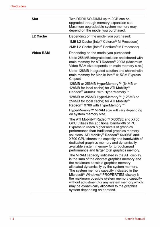
Slot Two DDRII SO-DIMM up to 2GB can be upgraded through memory expansion slot. Maximum upgradeable system memory may depend on the model you purchased.
L2 Cache Depending on the model you purchased:1MB L2 Cache (Intel® Celeron® M Processor)2MB L2 Cache (Intel® Pentium® M Processor)
Video RAM Depending on the model you purchased:Up to 256 MB integrated solution and shared with main memory for ATI Radeon® 200M (Maximum Video RAM size depends on main memory size.)Up to 128MB integrated solution and shared with main memory for Mobile Intel® 915GM Express Chipset128MB or 256MB HyperMemory™ (64MB or 128MB for local cache) for ATI Mobility® Radeon® X600SE with HyperMemory™128MB or 256MB HyperMemory™ (128MB or 256MB for local cache) for ATI Mobility® Radeon® X700 with HyperMemory™HyperMemory™ VRAM size will vary depending on system memory size.The ATI Mobility® Radeon® X600SE and X700 GPU utilizes the additional bandwidth of PCI Express to reach higher levels of graphics performance than traditional graphics memory solutions. ATI Mobility® Radeon® X600SE and X700 GPU shares the capacity and bandwidth of dedicated graphics memory and dynamically available system memory for turbocharged performance and larger total graphics memory.The VRAM capacity indicated in the ATI display is the sum of the discreet graphics memory and the maximum possible graphics memory allocated dynamically by the system memory. The system memory capacity indicated in the Microsoft® Windows® PROPERTIES display is the maximum possible system memory capacity without adjustment for any system memory which may be dynamically allocated to the graphics system depending on demand.
1-4 User’s Manual
Introduction
BIOS
Power
Floppy Disk Drive devices
TouchPad
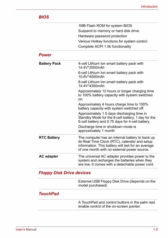
1MB Flash ROM for system BIOSSuspend to memory or hard disk driveHardware password protectionVarious Hotkey functions for system control Complete ACPI 1.0b functionality
Battery Pack 4-cell Lithium Ion smart battery pack with 14.4V*2000mAh 6-cell Lithium Ion smart battery pack with 10.8V*4000mAh 8-cell Lithium Ion smart battery pack with 14.4V*4300mAh Approximately 12 hours or longer charging time to 100% battery capacity with system switched on.Approximately 4 hours charge time to 100% battery capacity with system switched off.Approximately 1.5 days discharging time in Standby Mode for the 8-cell battery, 1 day for the 6-cell battery and 0.75 days for 4-cell battery.Discharge time in shutdown mode is approximately 1 month
RTC Battery The computer has an internal battery to back up its Real Time Clock (RTC), calender and setup information. This battery will last for an average of one month with no external power source.
AC adapter The universal AC adapter provides power to the system and recharges the batteries when they are low. It comes with a detachable power cord.
External USB Floppy Disk Drive (depends on the model purchased)
A TouchPad and control buttons in the palm rest enable control of the on-screen pointer.
User’s Manual 1-5

Introduction
Display
Disks
15.4” TFT screen with a resolution of 1280 horizontal x 800 vertical pixels WXGA
Fixed hard disk Depending on the model purchased, one of the following drives will be installed: 40.0 billion bytes (37.26GB)60.0 billion bytes (55.88GB)80.0 billion bytes (74.52GB)100.0 billion bytes (93.16GB)120.0 billion bytes (111.78GB)9.5mm 2.5" hard disk drive Either Parallel ATA Ultra DMA 100 or Serial ATA 1.0
CD-RW/DVD-ROM drive
Some models are equipped with a full-size CD-RW/DVD-ROM module that lets you record data to rewritable CD/CD-RWs as well as run either 12cm (4.72") or 8cm (3.15") CD/DVDs without using an adapter. It reads DVD-ROMs at maximum 8 speed and CD-ROMs at maximum 24 speed. It writes CD-Rs at up to 24 speed, CD-RWs at up to 24 speed. This drive supports the following formats:■ DVD-ROM ■ DVD-Video■ CD-R ■ CD-RW■ CD-DA ■ CD-Text■ Photo CD (single/multi-session)■ CD-ROM Mode1, Mode2■ CD-ROMXA Mode2 (Form1, Form2)■ Enhanced CD(CD-EXTRA)
1-6 User’s Manual
Introduction
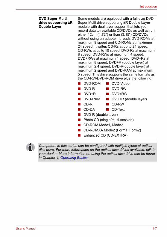
DVD Super Multi drive supporting ±R Double Layer
Some models are equipped with a full-size DVD Super Multi drive supporting ±R Double Layer module with dual layer support that lets you record data to rewritable CD/DVDs as well as run either 12cm (4.72") or 8cm (3.15") CD/DVDs without using an adapter. It reads DVD-ROMs at maximum 8 speed and CD-ROMs at maximum 24 speed. It writes CD-Rs at up to 24 speed, CD-RWs at up to 10 speed, DVD-Rs at maximum 8 speed, DVD-RWs at maximum 4 speed, DVD+RWs at maximum 4 speed, DVD+Rs at maximum 8 speed, DVD+R (double layer) at maximum 2.4 speed, DVD-R(double layer) at maximum 2 speed and DVD-RAM at maximum 5 speed. This drive supports the same formats as the CD-RW/DVD-ROM drive plus the following: ■ DVD-ROM ■ DVD-Video■ DVD-R ■ DVD-RW■ DVD+R ■ DVD+RW■ DVD-RAM ■ DVD+R (double layer)■ CD-R ■ CD-RW■ CD-DA ■ CD-Text■ DVD-R (double layer)■ Photo CD (single/multi-session)■ CD-ROM Mode1, Mode2■ CD-ROMXA Mode2 (Form1, Form2)■ Enhanced CD (CD-EXTRA)
Computers in this series can be configured with multiple types of optical disc drive. For more information on the optical disc drives available, talk to your dealer. More information on using the optical disc drive can be found in Chapter 4, Operating Basics.
User’s Manual 1-7
Introduction
Slots (depending on configuration)
Ports (depending on configuration)
Multimedia
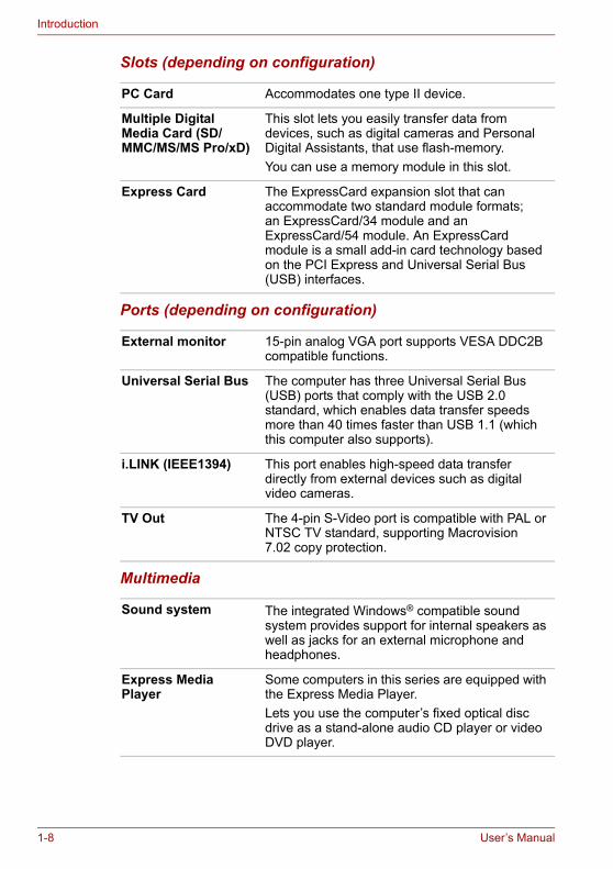
PC Card Accommodates one type II device.
Multiple Digital Media Card (SD/MMC/MS/MS Pro/xD)
This slot lets you easily transfer data from devices, such as digital cameras and Personal Digital Assistants, that use flash-memory.You can use a memory module in this slot.
Express Card The ExpressCard expansion slot that can accommodate two standard module formats; an ExpressCard/34 module and an ExpressCard/54 module. An ExpressCard module is a small add-in card technology based on the PCI Express and Universal Serial Bus (USB) interfaces.
External monitor 15-pin analog VGA port supports VESA DDC2B compatible functions.
Universal Serial Bus The computer has three Universal Serial Bus (USB) ports that comply with the USB 2.0 standard, which enables data transfer speeds more than 40 times faster than USB 1.1 (which this computer also supports).
i.LINK (IEEE1394) This port enables high-speed data transfer directly from external devices such as digital video cameras.
TV Out The 4-pin S-Video port is compatible with PAL or NTSC TV standard, supporting Macrovision 7.02 copy protection.
Sound system The integrated Windows® compatible sound system provides support for internal speakers as well as jacks for an external microphone and headphones.
Express Media Player
Some computers in this series are equipped with the Express Media Player.Lets you use the computer’s fixed optical disc drive as a stand-alone audio CD player or video DVD player.
1-8 User’s Manual
Introduction
Communications
Security
Security Lock Slot
Headphone jack A standard 3.5mm stereo jack is provided for the connection of external headphones or speakers.
Microphone jack A standard 3.5 mm mini microphone jack enables connection of monaural microphone input.
Modem An internal modem provides capability for data and fax communication. It supports the V.90 or V.92 standards depending on the region and provides a modem jack for connection to a telephone line. The speed of data and fax transfer depends on the analog telephone line conditions.
LAN The computer has built-in support for Ethernet LAN (10 megabits per second, 10BASE-T) and Fast Ethernet LAN (100 Mbps 100BASE-TX)
Wireless LAN Some computers in this series are equipped with a wireless LAN mini-PCI card that is compatible with other LAN systems that support the following: 802.11a+g wireless LAN module/ 802.11g wireless LAN module. It has a Frequency Channel Selection (2.4 or 5 GHz) and allows roaming over multiple channels.
Bluetooth (depends on the model you purchased)
Bluetooth is a short-range wireless technology used to create PANs (Personal Area Networks) among your devices, and with other nearby devices like mobile computers, mobile phones, and digital cameras.
Power-on password protectionTwo level password architecture
Receives an optional security lock in order to anchor the computer to a desk or other large, heavy object.
User’s Manual 1-9

Introduction
Special featuresThe following features are either unique to TOSHIBA computers or are advanced features, which make the computer more convenient to use.
Hotkeys Key combinations that let you quickly modify the system configuration directly from the keyboard without running a system configuration program.
Display Automatic Power off
This feature automatically cuts off power to the internal display when there is no input from the keyboard or pointing device for a specified time period. Power is restored when any key is pressed or when there is input from a pointing device. You can specify the time period in the TOSHIBA Power Saver utility.
Hard Disk Drive Automatic Power Off
This feature automatically cuts off power to the hard disk drive when it is not accessed for a specified time period. Power is restored when the hard disk is accessed. You can specify the time period in the TOSHIBA Power Saver utility.
System Automatic Standby/Hibernation
This feature automatically places the system into either Standby Mode or Hibernation Mode when there is no input or hardware access for a specified time period. You can specify the time period and select either System Standby or System Hibernate in the TOSHIBA Power Saver utility.
Keypad Overlay A ten-key pad is integrated into the keyboard. Refer to the Keypad overlay section in Chapter 5, The Keyboard, for instructions on using the keypad overlay.
Power-on Password Two levels of password security are available, Supervisor and User, which can prevent unauthorized access to your computer.
Battery Save Mode This feature lets you save battery power. You can specify the level of system power management in the TOSHIBA Power Saver utility.
Instant Security A Hotkey function which blanks the screen and activates password security to provide quick and easy data security.
Panel Power Off/On This feature turns power to the computer off when the display panel is closed and turns it back on when the panel is opened. You can specify the setting in the TOSHIBA Power Saver utility.
1-10 User’s Manual
Introduction
UtilitiesThis section describes preinstalled utilities and tells how to start them. For details on operations, refer to each utility’s online manual, help files or readme files.
Low Battery Automatic Hibernation
When battery power is exhausted to the point that computer operation cannot be continued, the system automatically enters Hibernation Mode and shuts itself down. You can specify the setting in the TOSHIBA Power Saver utility.
Hibernation This feature lets you turn off the power without exiting from your software. The contents of main memory are saved to the hard disk. When you turn on the power again, you can continue working right where you left off. Refer to the Turning off the power section in Chapter 3, Getting Started, for details.
Standby In Standby Mode, power to the system remains on, but the processor and all other devices are effectively in ’sleep mode’. When the computer is in Standby Mode, the Power LED flashes amber. The computer enters Standby Mode regardless of the Hibernate Mode setting. Refer to the Turning off the power section in Chapter 3, Getting Started, for details.
■ Before entering Standby mode, be sure to save your data.■ Do not install or remove a memory module while the computer is in
Standby mode. The computer or the module could be damaged.■ Do not remove the battery pack while the computer is in Standby mode.
Data in memory will be lost.
TOSHIBA Power Saver
TOSHIBA Power Saver provides configuration option to conserve power when the computer is running on either battery or mains power. You can start TOSHIBA Power Saver as follows:If Control Panel is in Category View:Start -> Control Panel -> Performance and Maintenance -> TOSHIBA Power SaverIf Control Panel is in Classic View:Start -> Control Panel -> TOSHIBA Power Saver
TOSHIBA Assist TOSHIBA Assist is a graphical user interface that provides easy access to help and services.
User’s Manual 1-11

Introduction
TOSHIBA PC Diagnostic Tool
TOSHIBA PC Diagnostic tool displays the basic information on the computer’s configuration and allows some of the built-in devices functionality to be tested.You can start the TOSHIBA PC Diagnostic Tool as follows:Start -> All Programs -> TOSHIBA -> Utilities -> PC Diagnostic Tool
TOSHIBA Controls This utility allows you to configure the computer’s audio/video control buttons and setup the audio/video playback applications.■ ButtonsAssign applications or functions to the Internet button and the CD/DVD button.The default settings are default browser and CD/DVD.■ Media AppsAllows the selection of the application to be used for audio and video playback.
DVD Player The DVD player is used to play DVD Video media through an on-screen interface and functions. Click Start, point to All Programs, point to InterVideo WinDVD then click InterVideo WinDVD.
ConfigFree ConfigFree is a suite of utilities to allow easy control of communication devices and network connections. ConfigFree also allows you to find communication problems and create profiles for easy switching between location and communication networks.To start ConfigFree, click the Start Button, point to All Programs, point to TOSHIBA, point to Networking and click ConfigFree.
TOSHIBA TouchPad On/Off Utility
Pressing Fn+F9 in a Windows® environment enables or disables the TouchPad function. When you press these hot keys, the current setting will change and be displayed as an icon onscreen.
RecordNow! Basic for TOSHIBA
You can create discs in several form ats including audio CDs that can be played on a standard stereo CD player and data discs to store the files and folders on your hard disk drive. This software can be used on a model with a CD-RW/DVD-ROM drive or a DVD Super Multi drive supporting ±R Double Layer.
1-12 User’s Manual
Introduction
DLA for TOSHIBA DLA (Drive Letter Access) is the packet writing software which provides the function to write files and/or folders to DVD+RW, DVD-RW or CD-RW media via a drive letter like a floppy disk or other removable disk media.
TOSHIBA Touch and Launch
TOSHIBA Touch and Launch is a tool that allows you to perform various tasks easily using the TouchPad. It is useful in the following conditions:■ To open a file located on the desktop whose
icon is obscured by a window.■ To open a page contained in the Internet
Explorer Favorites menu.■ To display the list of currently open windows
and change the active window.It also provides the following functions by customizing the settings.■ To open a file stored in a predefined folder.■ To quickly launch your frequently used
applications which have been registered.
TOSHIBA Zooming Utility
This utility allows you to enlarge or reduce the icon size on the desktop or the application window.
TOSHIBA HW Setup This program lets you customize your hardware settings according to the way you work with your computer and the peripherals you use. To access this utility, click Start, click Control Panel, click Printers and Other Hardware and select the TOSHIBA HW Setup icon.
TOSHIBA Fn-esse This program lets you define your own “shortcut” keys to quickly launch applications and speed your work in Windows. To start the utility, click Start, point to All Programs, point to TOSHIBA, point to Utilities and click Fn-esse.
TOSHIBA Accessibility
This utility lets you make the Fn key sticky, that is, you can press it once, release it, and then press an “F number” key. The Fn key remains active until another key is pressed.
User’s Manual 1-13
Introduction
OptionsYou can add a number of options to make your computer even more powerful and convenient to use. The following options are available:
TOSHIBA Virtual Sound
TOSHIBA Virtual Sound works as an audio filter using SRS WOW XT and SRS TruSurround XT functions provided by SRS Labs, Inc. in the United States. The audio filter enables you to enjoy improved quality sound and music on your computer.■ Turning on the featureTo turn on the feature of the audio filiter, follow the steps below.1. Select Start, point to All Programs, TOSHIBA,
Utilities and Virtual Sound.2. TOSHIBA Virtual Sound setting window is
displayed.3. Click “On” in the Basic Setting.
CD/DVD Drive Acoustic Silencer
This utility allows you to configure the read speed of CD drive. You can either configure Normal Mode, which operates the drive at its maximum speed for quick data access, or Quiet Mode which runs at single speed for CD audio and which can lessen operational noise. It is ineffective in DVD.
Memory Modules Two memory module can be installed in this computer.
Use only PC4200 compatible DDRII memory modules. See your TOSHIBA dealer for details
Battery Pack An additional battery pack can be purchased from your TOSHIBA dealer. Use it as a spare to increase your computer operating time.
AC adapter If you use your computer at more than one site frequently, it may be convenient to purchase an additional AC adapter for each site so you will not have to carry the adapter with you.
USB Floppy Disk Drive
Lets you attach a floppy disk drive to your computer by means of a USB cable.
1-14 User’s Manual
Chapter 2
The Grand Tour
This chapter identifies the various components of your computer. Become familiar with each component before you operate the computer.
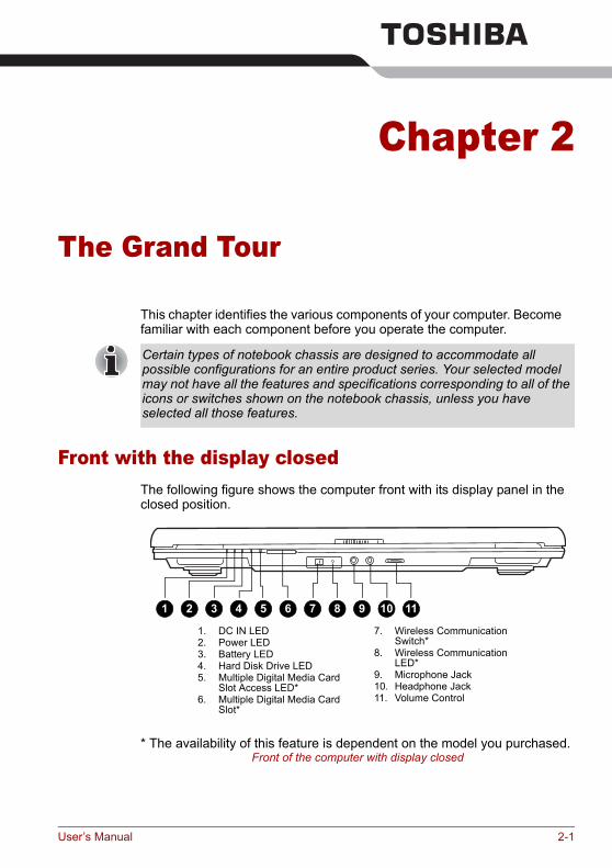
Front with the display closedThe following figure shows the computer front with its display panel in the closed position.
* The availability of this feature is dependent on the model you purchased.Front of the computer with display closed
Certain types of notebook chassis are designed to accommodate all possible configurations for an entire product series. Your selected model may not have all the features and specifications corresponding to all of the icons or switches shown on the notebook chassis, unless you have selected all those features.
1. DC IN LED2. Power LED3. Battery LED4. Hard Disk Drive LED5. Multiple Digital Media Card
Slot Access LED*6. Multiple Digital Media Card
Slot*
7. Wireless Communication Switch*
8. Wireless Communication LED*
9. Microphone Jack10. Headphone Jack11. Volume Control
5 76 8 1092 31 4 11
User’s Manual 2-1

The Grand Tour
DC IN LED The DC IN LED indicates the computer is connected to the AC adapter and it is plugged into an AC power source.
Power LED In normal operating mode, the Power LED is green or blue (depending on the model you purchased). If the system is in Standby Mode the LED will flash amber, while the LED will be off when the computer is turned off or is in Hibernation Mode.
Battery LED The Battery LED indicates the battery’s current charge/discharge status. It lights green or blue (depending on the model you purchased) when the battery is fully charged. It lights amber while the battery is being charged from the AC adapter. It flashes amber when the battery capacity is low.
Hard Disk Drive LED The Hard Disk Drive LED indicates that the hard disk drive is being accessed. Every time your computer runs a program, opens a file, or performs some other function in which it must access the hard disk drive, this light will go on.
Multiple Digital Media Card Slot Access LED*
The Multiple Digital Media Card Slot Access LED lights up when the Multiple Digital Media Card is accessed.(The availability of this function depends on the model you purchased.)
Multiple Digital Media Card Slot*
The Multiple Digital Media Card Slot allows you to use media cards from digital still cameras and various forms of portable information equipment.(The availability of this function depends on the model you purchased.)
Wireless Communication Switch*
The wireless communication switch turns on the wireless networking transceiver. The Wireless Communication LED beside it indicates that wireless networking is turned on. (The availability of this function depends on the model you purchased.)
Wireless Communication LED*
Indicates whether the wireless LAN is active or not.(The availability of this function depends on the model you purchased.)
Microphone Jack The standard 3.5 mm mini microphone jack enables connection of a three conductive type mini-jack for a monaural microphone.
2-2 User’s Manual

The Grand Tour
Right sideThe following figure shows the computer’s right side.
* The availability of this feature is dependent on the model you purchased.The right side of the computer
Headphone Jack The headphone jack lets you connect stereo headphones or other audio-output devices such as external speakers. Connecting headphones or other devices to this jack automatically disables the internal speakers.
Volume Control Use this dial to adjust the volume of the stereo speakers or headphones.
1. Express Card Slot*2. Optical Disc Drive
3. Optical Disc Drive LED
1 2 3
Express Card Slot This slot allows you to insert an Express Card. An ExpressCard module is a small, modular add-in card technology based on PCI Express and Universal Serial Bus (USB) interface. The max transmission rate at 2.5Gbps. Both 34mm type and 54mm type are supported.(The availability of this function depends on the model you purchased.)
Optical Disc Drive The computer is configured with a full-size optical disc drive module that lets you run either 12 cm (4.72") or 8 cm (3.15") discs without using an adapter. See the Drives section in this chapter for technical specifications on each drive and Chapter 4, Operating Basics, for information on using the drive and caring for discs.
Optical Disc Drive LED
This indicator lets you know when the Optical Disc Drive is being accessed.
User’s Manual 2-3
The Grand Tour
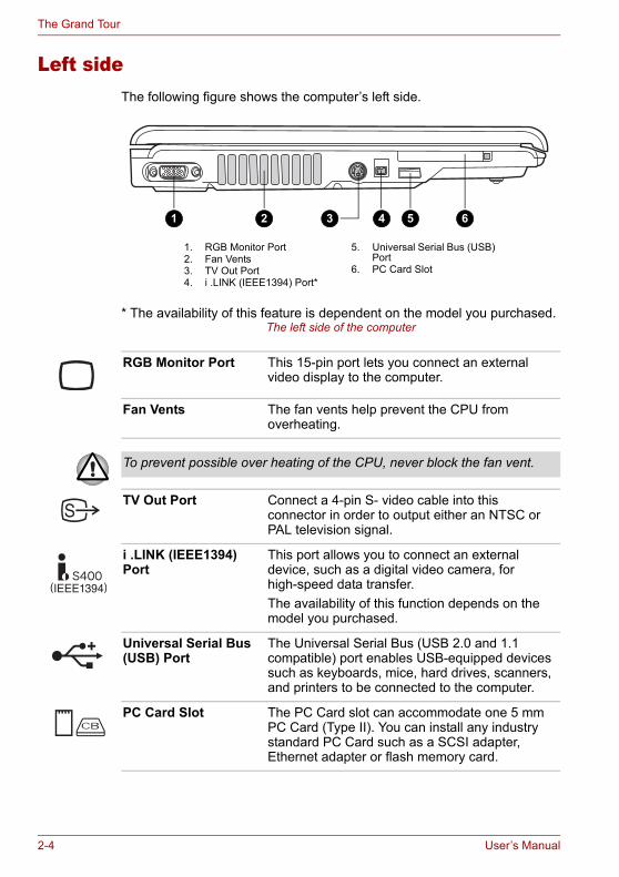
Left sideThe following figure shows the computer’s left side.
* The availability of this feature is dependent on the model you purchased.The left side of the computer
1. RGB Monitor Port2. Fan Vents3. TV Out Port4. i .LINK (IEEE1394) Port*
5. Universal Serial Bus (USB) Port
6. PC Card Slot
1 3 4 5 62
RGB Monitor Port This 15-pin port lets you connect an external video display to the computer.
Fan Vents The fan vents help prevent the CPU from overheating.
To prevent possible over heating of the CPU, never block the fan vent.
TV Out Port Connect a 4-pin S- video cable into this connector in order to output either an NTSC or PAL television signal.
i .LINK (IEEE1394) Port
This port allows you to connect an external device, such as a digital video camera, for high-speed data transfer.The availability of this function depends on the model you purchased.
Universal Serial Bus (USB) Port
The Universal Serial Bus (USB 2.0 and 1.1 compatible) port enables USB-equipped devices such as keyboards, mice, hard drives, scanners, and printers to be connected to the computer.
PC Card Slot The PC Card slot can accommodate one 5 mm PC Card (Type II). You can install any industry standard PC Card such as a SCSI adapter, Ethernet adapter or flash memory card.
2-4 User’s Manual
The Grand Tour
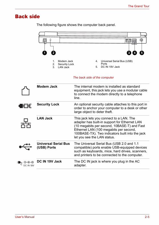
Back sideThe following figure shows the computer back panel.
The back side of the computer
1. Modem Jack2. Security Lock3. LAN Jack
4. Universal Serial Bus (USB) Ports
5. DC IN 19V Jack
1 2 3 4 5
Modem Jack The internal modem is installed as standard equipment, this jack lets you use a modular cable to connect the modem directly to a telephone line.
Security Lock An optional security cable attaches to this port in order to anchor your computer to a desk or other large object to deter theft.
LAN Jack This jack lets you connect to a LAN. The adapter has built-in support for Ethernet LAN (10 megabits per second, 10BASE-T) and Fast Ethernet LAN (100 megabits per second, 100BASE-TX). Two indicators built into the jack let you see the LAN status.
Universal Serial Bus (USB) Ports
The Universal Serial Bus (USB 2.0 and 1.1 compatible) ports enable USB-equipped devices such as keyboards, mice, hard drives, scanners, and printers to be connected to the computer.
DC IN 19V Jack The DC IN jack is where you plug in the AC adapter.
User’s Manual 2-5
The Grand Tour
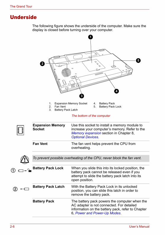
UndersideThe following figure shows the underside of the computer. Make sure the display is closed before turning over your computer.
The bottom of the computer
1. Expansion Memory Socket2. Fan Vent3. Battery Pack Latch
4. Battery Pack5. Battery Pack Lock
3
1
52
4
Expansion Memory Socket
Use this socket to install a memory module to increase your computer’s memory. Refer to the Memory expansion section in Chapter 8, Optional Devices.
Fan Vent The fan vent helps prevent the CPU from overheating.
To prevent possible overheating of the CPU, never block the fan vent.
Battery Pack Lock When you slide this into its locked position, the battery pack cannot be released even if you attempt to slide the battery pack latch into its open position.
Battery Pack Latch With the Battery Pack Lock in its unlocked position, you can slide this latch in order to remove the battery pack.
Battery Pack The battery pack powers the computer when the AC adapter is not connected. For detailed information on the battery pack, refer to Chapter 6, Power and Power-Up Modes.
2-6 User’s Manual
The Grand Tour
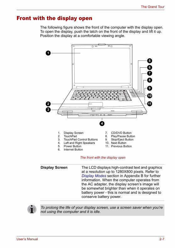
Front with the display openThe following figure shows the front of the computer with the display open. To open the display, push the latch on the front of the display and lift it up. Position the display at a comfortable viewing angle.
The front with the display open
1. Display Screen2. TouchPad3. TouchPad Control Buttons4. Left and Right Speakers5. Power Button6. Internet Button
7. CD/DVD Button8. Play/Pause Button9. Stop/Eject Button10. Next Button11. Previous Button
1
5
6
7
8
9
10
112
3
4
Display Screen The LCD displays high-contrast text and graphics at a resolution up to 1280X800 pixels. Refer to Display Modes section in Appendix B for further information. When the computer operates from the AC adapter, the display screen’s image will be somewhat brighter than when it operates on battery power - this is normal and is designed to conserve battery power.
To prolong the life of your display screen, use a screen saver when you’re not using the computer and it is idle.
User’s Manual 2-7
The Grand Tour
TouchPad The TouchPad pointing device is located in the center of the palm rest and is used to control the on-screen pointer. Refer to the Using the Touch Pad section in Chapter 4, Operating Basics.
TouchPad Control Buttons
Control buttons below the TouchPad let you select menu items or manipulate text and graphics designated by the on-screen pointer.
Left and Right Speakers
The computer provides two speakers for stereo sound reproduction.
Power Button Press the power button to turn the computer’s power on and off. There is an LED inside the power button (depending on the model you purchased) which shines either green or blue (depending on the model you purchased) when the system is on.
Internet Button Press the Internet button to open your default web brower.The button setting can be changed in TOSHIBA Controls properties. To access the TOSHIBA Controls properties, click start, click the Control Panel, click Printers and Other Hardware and select the TOSHIBA Controls icon.(The availability of this function depends on the model you purchased.)
CD/DVD Button Pressing this button when the computer’s power is off will run Express Media Player. Once Express Media Player is launched, the power indicator turns on, the audio control buttons are enabled and pressing this button again will do nothing. If you press this button while the computer is switched on or switched off into Standby Mode, it will launch either Windows Media® Player or WinDVD depending on the media that is loaded.The button setting can be changed in TOSHIBA Controls properties. To access the TOSHIBA Controls properties, click start, click the Control Panel, click Printers and Other Hardware and select the TOSHIBA Controls icon.(The availability of this function depends on the model you purchased.)
When you use Express Media Player, please assign the CD/DVD button to “CD/DVD” in TOSHIBA Controls Properties.
2-8 User’s Manual
The Grand Tour
Keyboard Indicators
Play/Pause Button Press this button to begin playing an audio CD, a DVD movie or digital audio files. This button also acts as a Pause button. (The availability of this function depends on the model you purchased.)
Stop/Eject Button Stops playing the CD, DVD or digital audio. Also ejects a disc from the tray.(The availability of this function depends on the model you purchased.)
Next Button Skips forward to the next track, chapter or digital file. Refer to Chapter 4, Operating Basics, for details.(The availability of this function depends on the model you purchased.)
Previous Button Skips backwards to the previous track, chapter or digital file. Refer to Chapter 4, Operating Basics, for details.(The availability of this function depends on the model you purchased.)
If Random or Shuffle is selected in Windows® Media Player, selecting Next or Previous advances to a random selection.
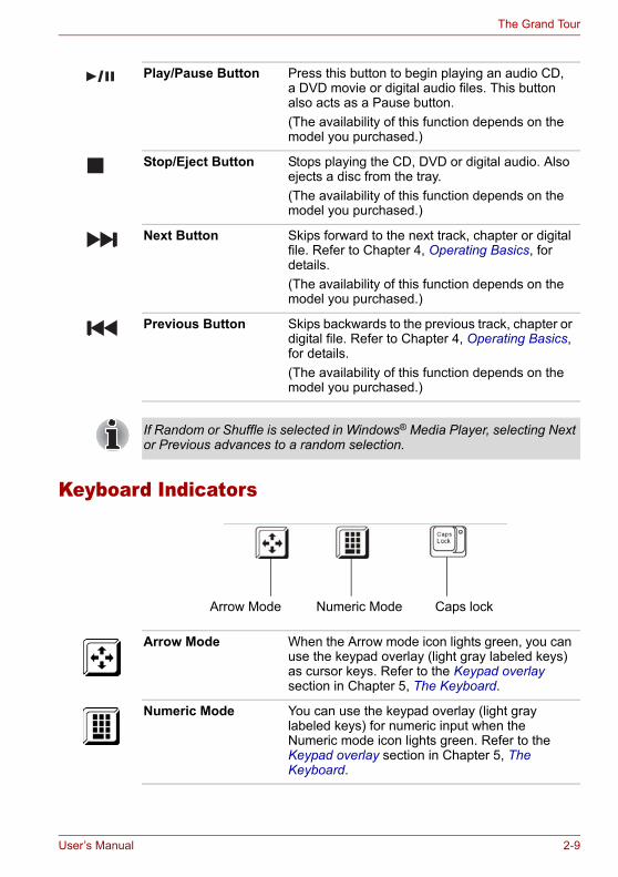
Arrow Mode Numeric Mode Caps lock
Arrow Mode When the Arrow mode icon lights green, you can use the keypad overlay (light gray labeled keys) as cursor keys. Refer to the Keypad overlay section in Chapter 5, The Keyboard.
Numeric Mode You can use the keypad overlay (light gray labeled keys) for numeric input when the Numeric mode icon lights green. Refer to the Keypad overlay section in Chapter 5, The Keyboard.
User’s Manual 2-9

The Grand Tour
Optical Disc driveThe computer will either have a CD-RW/DVD-ROM drive, or a single layer or dual layer DVD Super Multi drive supporting ±R Double Layer depending on its configuration. An ATAPI interface controller is used for the operation of these optical drives. When the computer is accessing a disc, an indicator on the drive glows.
Region codes for DVD drives and mediaThe disc drive and its media are manufactured according to the specifications of six marketing regions. When you purchase DVD-Video, make sure it matches your drive, otherwise it will not play properly.
Writable discsThis section describes the types of writable discs. Check the specifications for your drive to for the type of discs it can write. Use Record Now! to write compact discs. Refer to Chapter 4, Operating Basics.
CDs■ CD-R discs can be written only once. The recorded data cannot be
erased or changed.■ CD-RW discs can be recorded more than once. Use either 1x, 2x, or
4x multi-speed CD-RW discs or high-speed 4x to 10x discs. The write speed of ultra-speed CD-RW discs is a maximum of 24x speed.
Caps Lock The Caps Lock LED lights when you press the Caps Lock key. When this light is on, pressing a letter key on the keyboard produces an uppercase (capital) letter.
Code Region
1 Canada, United States
2 Japan, Europe, South Africa, Middle East
3 Southeast Asia, East Asia
4 Australia, New Zealand, Pacific Islands, Central America, South America, Caribbean
5 Russia, Indian Subcontinent, Africa, North Korea, Mongolia
6 China
2-10 User’s Manual

The Grand Tour
DVDs■ DVD-R and DVD+R discs can be written only once. The recorded data
cannot be erased or changed.■ DVD-RW, DVD+RW and DVD-RAM discs can be recorded more than
once.
CD-RW/DVD-ROM driveThe full-size CD-RW/DVD-ROM drive module lets you record data to rewritable CDs as well as run either 12 cm (4.72") or 8 cm (3.15") discs without using an adapter.
DVD Super Multi drive supporting ±R Double Layer The full-size DVD Super Multi drive supporting ±R Double Layer module lets you record data to rewritable discs as well as run either 12cm (4.72") or 8cm (3.15") discs without using an adapter.
This drive cannot use discs that allow writing faster than 8x speed or faster (DVD-R and DVD+R with Single Layer), 4x speed or faster (DVD-RW and DVD+RW), 5x speed (DVD-RAM) or ultra-speed or faster (CD-RW).
The read speed is slower at the center of a disc and faster at the other edge.
DVD read 8 speed (maximum)CD read 24 speed (maximum)CD-R write 24 speed (maximum)CD-RW write 24 speed (maximum, ultra-speed media)
The read speed is slower at the center of a disc and faster at the other edge.
DVD read 8 speed (maximum)DVD-R write 8 speed (maximum)DVD-RW write 4 speed (maximum)DVD+R write 8 speed (maximum)DVD+RW write 4 speed (maximum)DVD-RAM write 5 speed (maximum)CD read 24 speed (maximum)CD-R write 24 speed (maximum)CD-RW write 10 speed (maximum, ultra-speed media)DVD+R (DL) write 2.4 speed (maximum)DVD-R(DL) write 2 speed (maximum)
User’s Manual 2-11
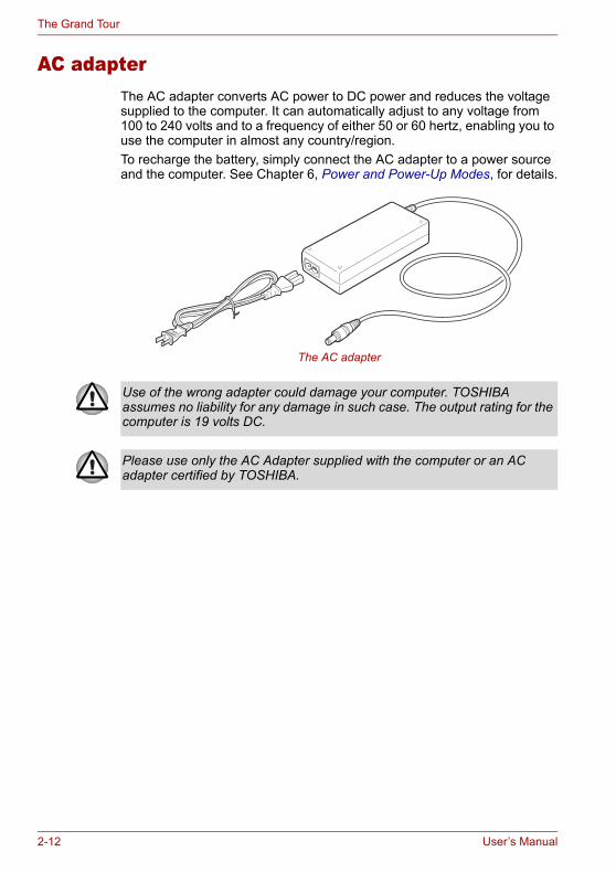
The Grand Tour
AC adapterThe AC adapter converts AC power to DC power and reduces the voltage supplied to the computer. It can automatically adjust to any voltage from 100 to 240 volts and to a frequency of either 50 or 60 hertz, enabling you to use the computer in almost any country/region.To recharge the battery, simply connect the AC adapter to a power source and the computer. See Chapter 6, Power and Power-Up Modes, for details.
The AC adapter
Use of the wrong adapter could damage your computer. TOSHIBA assumes no liability for any damage in such case. The output rating for the computer is 19 volts DC.
Please use only the AC Adapter supplied with the computer or an AC adapter certified by TOSHIBA.
2-12 User’s Manual
Chapter 3
Getting StartedThis chapter provides basic information to get you started using your computer. It covers the following topics:■ Setting up your work space - for your health and safety
■ Connecting the AC adapter■ Opening the display■ Turning on the power■ Starting up for the first time■ Turning off the power■ Restarting the computer■ Restoring the pre-installed software from the Product Recovery media.
Setting up your work spaceEstablishing a comfortable work site is important for you and your computer. A poor work environment or stressful work habits can result in discomfort or serious injury from repetitive strain to your hands, wrists or other joints. Proper ambient conditions should also be maintained for the computer’s operation. This section discusses the following topics:■ General conditions■ Placement of the computer and peripheral devices■ Seating and posture■ Lighting■ Work habits
Be sure also to read Instruction Manual for Safety & Comfort. This guide, which is included with the computer, explains product liability.
All users should be sure to carefully read the section Starting up for the first time, which describes the actions to take when you first turn on the power to the computer.
User’s Manual 3-1

Getting Started
General conditionsIn general, if you are comfortable, so is your computer, but read the following to make sure your work site provides a proper environment.■ Make sure there is adequate space around the computer for proper
ventilation.■ Make sure the AC power cord connects to an outlet that is close to the
computer and easily accessible.■ The temperature should be 5 to 35 degrees Centigrade
(41 to 95 degrees Fahrenheit) and the relative humidity should be 20 to 80 percent.
■ Avoid areas where rapid or extreme changes in temperature or humidity may occur.
■ Keep the computer free of dust, moisture, and exposure to direct sunlight.
■ Keep the computer away from heat sources, such as electric heaters.■ Do not use the computer near liquids or corrosive chemicals.■ Some components in the computer, including data storage media, can
be damaged by magnets. Do not place the computer near magnetic objects or bring magnetic objects close to the computer. Be careful of objects, such as stereo speakers, that produce strong magnetic fields during operation. Also, be careful with metal objects, such as bracelets, which can be inadvertently magnetized.
■ Do not operate the computer in close proximity to a mobile phone.■ Leave ample ventilation room for the fan. Ensure that there are no
obstructions around any of the system inlets or exhaust vents.
Placement of computerPosition the computer and peripheral devices to provide comfort and safety.■ Set the computer on a flat surface at a comfortable height and distance.
The display should be no higher than eye level to avoid eye strain.■ Place the computer so that it is directly in front of you when you work
and make sure you have adequate space to easily operate other devices.
■ Allow adequate space behind the computer to let you freely adjust the display. The display should be angled to reduce glare and maximize visibility.
■ If you use a paper holder, set it at about the same height and distance as the computer.
3-2 User’s Manual
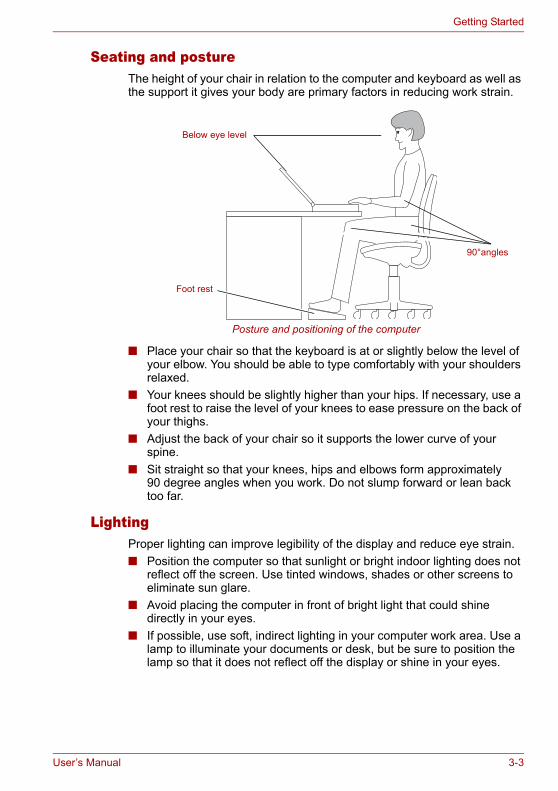
Getting Started
Seating and postureThe height of your chair in relation to the computer and keyboard as well as the support it gives your body are primary factors in reducing work strain.
Posture and positioning of the computer
■ Place your chair so that the keyboard is at or slightly below the level of your elbow. You should be able to type comfortably with your shoulders relaxed.
■ Your knees should be slightly higher than your hips. If necessary, use a foot rest to raise the level of your knees to ease pressure on the back of your thighs.
■ Adjust the back of your chair so it supports the lower curve of your spine.
■ Sit straight so that your knees, hips and elbows form approximately 90 degree angles when you work. Do not slump forward or lean back too far.
LightingProper lighting can improve legibility of the display and reduce eye strain.■ Position the computer so that sunlight or bright indoor lighting does not
reflect off the screen. Use tinted windows, shades or other screens to eliminate sun glare.
■ Avoid placing the computer in front of bright light that could shine directly in your eyes.
■ If possible, use soft, indirect lighting in your computer work area. Use a lamp to illuminate your documents or desk, but be sure to position the lamp so that it does not reflect off the display or shine in your eyes.
90°angles
Below eye level
Foot rest
User’s Manual 3-3
Getting Started
Work habitsA key to avoiding discomfort or injury from repetitive strain is to vary your activities.If possible, schedule a variety of tasks into your work day. If you must spend long periods at the computer, finding ways to break up the routine can reduce stress and improve your efficiency.■ Sit in a relaxed posture. Good positioning of your chair and equipment
as described earlier can reduce tension in your shoulders or neck and ease back strain.
■ Vary your posture frequently.■ Occasionally stand up and stretch or exercise briefly.■ Exercise and stretch your wrists and hands a number of times during
the day.■ Frequently, look away from the computer and focus your eyes on a
distant object for several seconds, for example 30 seconds every 15 minutes.
■ Take frequent short breaks instead of one or two long breaks, for example, two or three minutes every half hour.
■ Have your eyes examined regularly and visit a doctor promptly, if you suspect you might be suffering from a repetitive strain injury.
■ Please check every couple of months to ensure the fan inlets or exhaust vents (see sections 2-5 and 2-7) are unobstructed. Clean them if necessary.
A number of books are available on ergonomics and repetitive strain injury or repetitive stress syndrome. For more information on these topics or for pointers on exercises for such stress points as hands and wrists, please check with your library or book vendor. Also refer to the computer’s Safety Instruction Manual.
3-4 User’s Manual
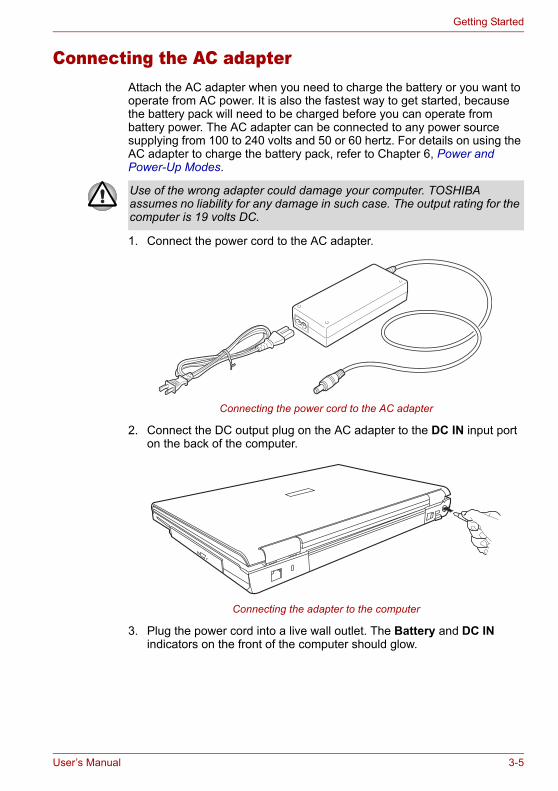
Getting Started
Connecting the AC adapterAttach the AC adapter when you need to charge the battery or you want to operate from AC power. It is also the fastest way to get started, because the battery pack will need to be charged before you can operate from battery power. The AC adapter can be connected to any power source supplying from 100 to 240 volts and 50 or 60 hertz. For details on using the AC adapter to charge the battery pack, refer to Chapter 6, Power and Power-Up Modes.
1. Connect the power cord to the AC adapter.
Connecting the power cord to the AC adapter
2. Connect the DC output plug on the AC adapter to the DC IN input port on the back of the computer.
Connecting the adapter to the computer
3. Plug the power cord into a live wall outlet. The Battery and DC IN indicators on the front of the computer should glow.
Use of the wrong adapter could damage your computer. TOSHIBA assumes no liability for any damage in such case. The output rating for the computer is 19 volts DC.
User’s Manual 3-5
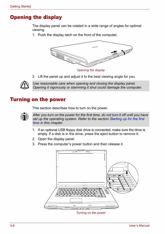
Getting Started
Opening the displayThe display panel can be rotated in a wide range of angles for optimal viewing.1. Push the display latch on the front of the computer.
Opening the display
2. Lift the panel up and adjust it to the best viewing angle for you.
Turning on the powerThis section describes how to turn on the power.
1. If an optional USB floppy disk drive is connected, make sure the drive is empty. If a disk is in the drive, press the eject button to remove it.
2. Open the display panel.3. Press the computer’s power button and then release it.
Turning on the power
Use reasonable care when opening and closing the display panel. Opening it vigorously or slamming it shut could damage the computer.
After you turn on the power for the first time, do not turn it off until you have set up the operating system. Refer to the section Starting up for the first time in this chapter.
3-6 User’s Manual

Getting Started
Starting up for the first timeWhen you first turn on the power, the computer’s initial screen is the Windows® XP Startup Screen Logo. Follow the on-screen directions for each screen. During setup, you can click the Back button to return to the previous screen.Be sure to read the Windows® Operating System End User License Agreement carefully.
Turning off the powerThe power can be turned off in one of three modes, either Shutdown Mode (also known as Boot Mode), Hibernation Mode or Standby Mode.
Shut Down mode (Boot mode)When you turn off the power in Shut Down mode, no data is saved and the computer will boot to the operating system’s main screen.1. If you have entered data, save it to the hard disk, to writable optical
media or to a disk.2. Make sure all disk activity has stopped, then remove the optical disc or
floppy disk.
3. Click Start and click Turn Off Computer. From the Turn Off Computer window click Turn Off.
4. Turn off the power to any peripheral devices.
Hibernation modeThe hibernation feature saves the contents of memory to the hard disk when the computer is turned off. The next time the computer is turned on, the previous state is restored. The hibernation feature does not save the status of peripheral devices.
Make sure the built-in hard disk drive and optical disc drive indicators are off before you switch the computer off. If you turn off the power while a disk is being accessed, you can lose data or damage the disk.
Do not turn the computer or devices back on immediately. Wait a moment to let all capacitors fully discharge.
1. While entering hibernation mode, the computer saves the contents of memory to the Hard Disk Drive. Data will be lost if you remove the battery or disconnect the AC adapter before the save is completed. Wait for the Built-in Hard Disk Drive indicator to go out.
2. Do not install or remove a memory module while the computer is in hibernation mode. Data will be lost.
User’s Manual 3-7
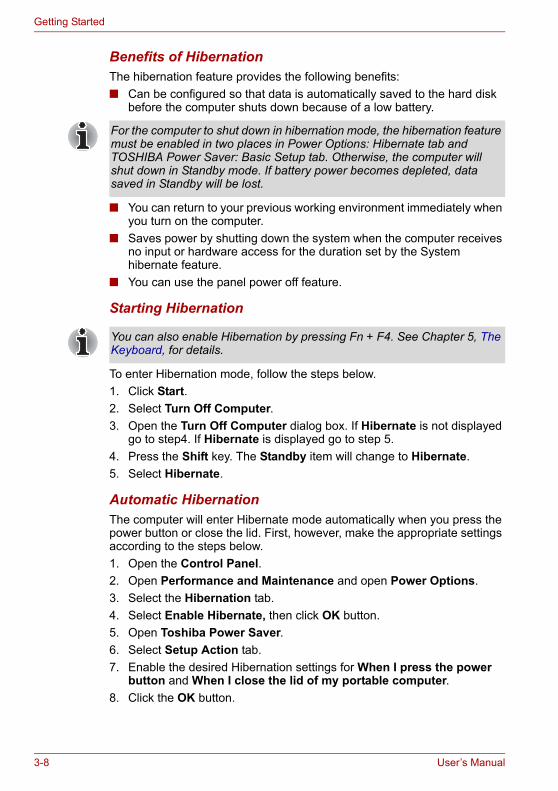
Getting Started
Benefits of HibernationThe hibernation feature provides the following benefits:■ Can be configured so that data is automatically saved to the hard disk
before the computer shuts down because of a low battery.
■ You can return to your previous working environment immediately when you turn on the computer.
■ Saves power by shutting down the system when the computer receives no input or hardware access for the duration set by the System hibernate feature.
■ You can use the panel power off feature.
Starting Hibernation
To enter Hibernation mode, follow the steps below.1. Click Start.2. Select Turn Off Computer.3. Open the Turn Off Computer dialog box. If Hibernate is not displayed
go to step4. If Hibernate is displayed go to step 5.4. Press the Shift key. The Standby item will change to Hibernate.5. Select Hibernate.
Automatic HibernationThe computer will enter Hibernate mode automatically when you press the power button or close the lid. First, however, make the appropriate settings according to the steps below.1. Open the Control Panel.2. Open Performance and Maintenance and open Power Options.3. Select the Hibernation tab.4. Select Enable Hibernate, then click OK button.5. Open Toshiba Power Saver.6. Select Setup Action tab.7. Enable the desired Hibernation settings for When I press the power
button and When I close the lid of my portable computer.8. Click the OK button.
For the computer to shut down in hibernation mode, the hibernation feature must be enabled in two places in Power Options: Hibernate tab and TOSHIBA Power Saver: Basic Setup tab. Otherwise, the computer will shut down in Standby mode. If battery power becomes depleted, data saved in Standby will be lost.
You can also enable Hibernation by pressing Fn + F4. See Chapter 5, The Keyboard, for details.
3-8 User’s Manual
Getting Started
Data save in hibernation modeWhen you turn off the power in hibernation mode, the computer takes a moment to save current memory data to the hard disk. During this time, the Built-in Hard Disk Drive indicator will light.After the computer has saved all data to the hard disk, and it has completely shutdown, you can turn off the power to any peripheral devices.
Standby modeIn standby mode the power remains on, but the CPU and all other devices are in sleep mode.
Standby precautions■ Before entering Standby mode, be sure to save your data.■ Do not remove/install memory or remove power components:
■ Do not remove/install memory modules - the computer or the module itself could be damaged.
■ Do not remove the battery pack.In any of the above cases, the data being maintained by Standby Mode will be lost.
■ If you carry the computer on board an aircraft or into a hospital, be sure to shut down the computer in hibernation mode or in shutdown mode to avoid radio signal interference.
Do not turn the computer or devices back on immediately. Wait a moment to let all capacitors fully discharge.
■ If the computer is not used or accessed in any way, including areas such as the receipt of an e-mail, for approximately 15 or 30 minutes when the AC adapter is connected, it will automatically enter Standby Mode. This function is the default setting within the TOSHIBA Power Saver utility.
■ To restore operation, press the power button.■ If the computer automatically enters Standby mode while a network
application is active, the application might not be restored when the computer wakes up from Standby.
■ To prevent the computer from automatically entering Standby Mode you should disable the Standby feature within the TOSHIBA Power Saver utility. However, please note that disabling this feature will mean the computer is not longer Energy Star compliant.
User’s Manual 3-9
Getting Started
Benefits of standbyThe standby feature provides the following benefits:■ Restores the previous working environment more rapidly than
Hibernation Mode.■ Saves power by shutting down the system when the computer receives
no input or hardware access for the duration set by the System Standby feature.
■ You can use the panel power off feature.
Enabling Standby
You can enter standby mode in one of three ways:1. Click Start, then Turn Off Computer and then Stand By.2. Close the display panel. This feature must be enabled. Refer to the
Setup Action tab in TOSHIBA Power Saver Utility described in the Control Panel.
3. Press the power button. This feature must be enabled. Refer to the Setup Action tab in TOSHIBA Power Saver Utility described in the Control Panel.
When you turn the power back on, you can continue where you left when you shut down the computer.
Standby limitationsStandby will not function under the following conditions:■ Power is turned back on immediately after shutting down.■ Memory circuits are exposed to static electricity or electrical noise.
You can also enable Standby by pressing Fn + F3. See Chapter 5, The Keyboard, for details.
■ When the computer is shut down in standby mode, the power indicator glows amber.
■ If you are running the computer on battery power, you can lengthen the operating time by shutting down into Hibernation Mode. Standby Mode consumes more power from the battery when the computer is switched off.
3-10 User’s Manual

Getting Started
Restarting the computerCertain conditions require that you reset the system. For example, if:■ You change certain computer settings.■ An error occurs and the computer does not respond to your keyboard
commands.There are three ways to reset the computer system:1. Click start then click Turn off computer. From the Turn off
computer menu select Restart.2. Press Ctrl + Alt + Del to display the Windows® Task Manager, then
select Shutdown and Restart.3. Press the power button to turn the computer off, then press it a second
to time in order to restart.
Restoring the preinstalled software If preinstalled files are damaged, use the Product Recovery disc to restore them. To restore the operating system and all preinstalled software, follow the steps below.
1. Load the Product Recovery disc in the drive and turn off the computer’s power.
2. Switch on the computer and, when the In Touch with Tomorrow TOSHIBA prompt appears, press the F12 key to display the Boot Menu.
3. Use the up or down cursor key to select the CD-ROM/DVD drive in the display menu.
4. Follow the on-screen instructions.
Restoring TOSHIBA utilities and driversIf Windows is working properly, individual drivers or applications can be separately restored. The TOSHIBA Tools & Utilities folder (C:\TOOLSCD) contains drivers and applications, which are included with your computer system. If your system drivers or applications have become damaged in some way, you can reinstall most of the components from this folder.Create a copy of this folder to an external media for more convenience.
Only use step 3 if the operating system freezes or locks up due to a crash. Performing step 3 should only ever be a last resort as you will lose all unsaved data and could potentially damage critical files.
When you reinstall the Windows® operating system, the hard disk will be reformatted and all data will be lost.
Please use the Express Media Player Recovery CD to reinstall the Express Media Player applications before you reinstall the Windows® operating system. (the availability of this function depends on the model you purchased).
User’s Manual 3-11

Getting Started
3-12 User’s Manual
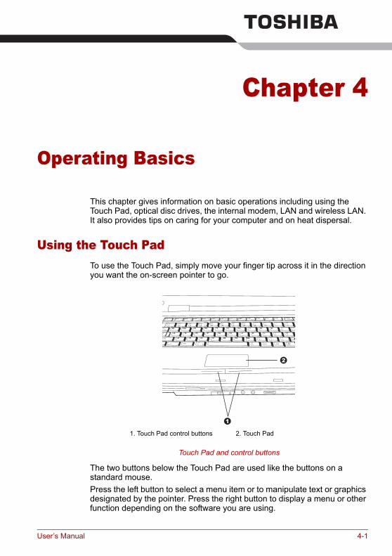
Chapter 4
Operating Basics
This chapter gives information on basic operations including using the Touch Pad, optical disc drives, the internal modem, LAN and wireless LAN. It also provides tips on caring for your computer and on heat dispersal.
Using the Touch PadTo use the Touch Pad, simply move your finger tip across it in the direction you want the on-screen pointer to go.
Touch Pad and control buttons
The two buttons below the Touch Pad are used like the buttons on a standard mouse.Press the left button to select a menu item or to manipulate text or graphics designated by the pointer. Press the right button to display a menu or other function depending on the software you are using.
1
2
1. Touch Pad control buttons 2. Touch Pad
User’s Manual 4-1
Operating Basics
The Touch Pad has similar functions to a two-button mouse with a scroll wheel. For some functions, you can tap it instead of pressing a button.
Using the internal modemThis section describes how to setup the modem and use it to connect to other computer systems. Refer to the computer’s online help files and the online help files for your modem software, for more information.
IMPORTANT SAFETY INSTRUCTIONS
Do not press on the Touch Pad too hard or press a sharp object such as a ball point pen against it. The Touch Pad could be damaged.
You can customize pointing device actions in Mouse Properties. Open the Control Panel, select the Mouse icon and press Enter to open the Mouse Properties window.Click: Click the left control button or tap the Touch Pad once.Double-click: Click the left control button twice or tap the Touch Pad twice.Scroll Vertical: Move your finger up or down the right edge of the Touch Pad. Scroll Horizontal: Move your finger left or right along the bottom edge of the Touch Pad.
The internal modem does not support the voice functions described in the help files. All data and fax functions are supported.
■ In case of a lightning storm, unplug the modem cable from the telephone jack.
■ Do not connect the modem to a digital telephone line. A digital line will damage the modem.
When using your telephone equipment, basic safety precautions should always be followed to reduce the risk of fire, electric shock and injury to persons, including the following:1. Do not use this product near water, for example, near a bathtub, wash
bowl, kitchen sink or laundry tub, in a wet basement or near a swimming pool.
2. Avoid using a telephone (other than a cordless type) during an electrical storm. There may be a remote risk of electric shock from lightning.
3. Do not use the telephone to report a gas leak in the vicinity of the leak.4. Use only the power cord indicated in this manual.
4-2 User’s Manual
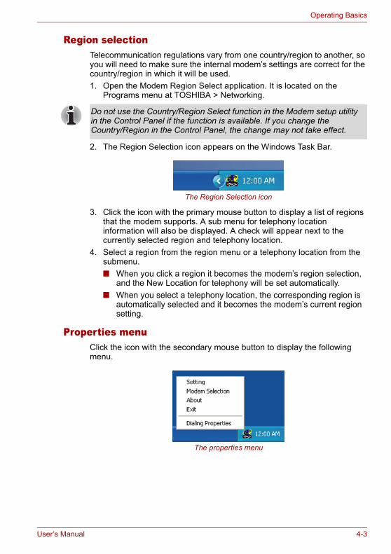
Operating Basics
Region selectionTelecommunication regulations vary from one country/region to another, so you will need to make sure the internal modem’s settings are correct for the country/region in which it will be used.1. Open the Modem Region Select application. It is located on the
Programs menu at TOSHIBA > Networking.
2. The Region Selection icon appears on the Windows Task Bar.
The Region Selection icon
3. Click the icon with the primary mouse button to display a list of regions that the modem supports. A sub menu for telephony location information will also be displayed. A check will appear next to the currently selected region and telephony location.
4. Select a region from the region menu or a telephony location from the submenu.■ When you click a region it becomes the modem’s region selection,
and the New Location for telephony will be set automatically.■ When you select a telephony location, the corresponding region is
automatically selected and it becomes the modem’s current region setting.
Properties menuClick the icon with the secondary mouse button to display the following menu.
The properties menu
Do not use the Country/Region Select function in the Modem setup utility in the Control Panel if the function is available. If you change the Country/Region in the Control Panel, the change may not take effect.
User’s Manual 4-3
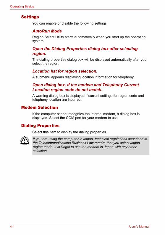
Operating Basics
SettingsYou can enable or disable the following settings:
AutoRun ModeRegion Select Utility starts automatically when you start up the operating system.
Open the Dialing Properties dialog box after selecting region.The dialing properties dialog box will be displayed automatically after you select the region.
Location list for region selection.A submenu appears displaying location information for telephony.
Open dialog box, if the modem and Telephony Current Location region code do not match.A warning dialog box is displayed if current settings for region code and telephony location are incorrect.
Modem SelectionIf the computer cannot recognize the internal modem, a dialog box is displayed. Select the COM port for your modem to use.
Dialing PropertiesSelect this item to display the dialing properties.
If you are using the computer in Japan, technical regulations described in the Telecommunications Business Law require that you select Japan region mode. It is illegal to use the modem in Japan with any other selection.
4-4 User’s Manual
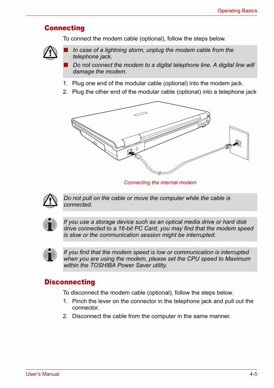
Operating Basics
ConnectingTo connect the modem cable (optional), follow the steps below.
1. Plug one end of the modular cable (optional) into the modem jack.2. Plug the other end of the modular cable (optional) into a telephone jack
Connecting the internal modem
DisconnectingTo disconnect the modem cable (optional), follow the steps below.1. Pinch the lever on the connector in the telephone jack and pull out the
connector.2. Disconnect the cable from the computer in the same manner.
■ In case of a lightning storm, unplug the modem cable from the telephone jack.
■ Do not connect the modem to a digital telephone line. A digital line will damage the modem.
Do not pull on the cable or move the computer while the cable is connected.
If you use a storage device such as an optical media drive or hard disk drive connected to a 16-bit PC Card, you may find that the modem speed is slow or the communication session might be interrupted.
If you find that the modem speed is low or communication is interrupted when you are using the modem, please set the CPU speed to Maximum within the TOSHIBA Power Saver utility.
User’s Manual 4-5
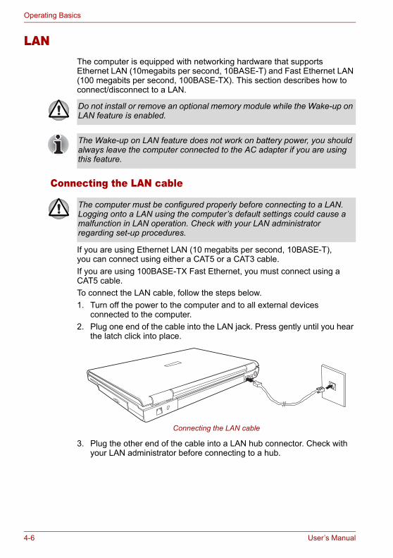
Operating Basics
LANThe computer is equipped with networking hardware that supports Ethernet LAN (10megabits per second, 10BASE-T) and Fast Ethernet LAN (100 megabits per second, 100BASE-TX). This section describes how to connect/disconnect to a LAN.
Connecting the LAN cable
If you are using Ethernet LAN (10 megabits per second, 10BASE-T), you can connect using either a CAT5 or a CAT3 cable.If you are using 100BASE-TX Fast Ethernet, you must connect using a CAT5 cable.To connect the LAN cable, follow the steps below.1. Turn off the power to the computer and to all external devices
connected to the computer.2. Plug one end of the cable into the LAN jack. Press gently until you hear
the latch click into place.
Connecting the LAN cable
3. Plug the other end of the cable into a LAN hub connector. Check with your LAN administrator before connecting to a hub.
Do not install or remove an optional memory module while the Wake-up on LAN feature is enabled.
The Wake-up on LAN feature does not work on battery power, you should always leave the computer connected to the AC adapter if you are using this feature.
The computer must be configured properly before connecting to a LAN. Logging onto a LAN using the computer’s default settings could cause a malfunction in LAN operation. Check with your LAN administrator regarding set-up procedures.
4-6 User’s Manual
Operating Basics
Disconnecting the LAN cableTo disconnect the LAN cable, follow the steps below.1. Pinch the lever on the connector in the computer’s LAN jack and pull
out the connector.2. Disconnect the cable from the LAN hub in the same manner. Check
with your LAN administrator before disconnecting from the hub.
Wireless LANThe wireless LAN is compatible with other LAN systems that comply with the IEEE 802.11a+g or 802.11g wireless LAN standards.It supports the following:■ Automatic Transmit Rate Select mechanism in the transmit range of 54,
24, 12 and 6 Mbit/s.■ Advanced Encryption Standard (AES) data encryption, based on 128bit
encryption algorithm. (Revision G, A/G combo type.)
■ Frequency Channel Selection (5GHz and 2.4 GHz)■ Roaming over multiple channels■ Card Power Management■ Wired Equivalent Privacy (WEP) data encryption
Wireless LAN disclaimerThe transmission speed over the wireless LAN and the distance over which wireless LAN can reach may vary depending on surrounding electromagnetic environment, obstacles, access point design and configuration, and client design and software/hardware configurations. The actual transmission speed will be lower than the theoretical maximum speed.
Security1. TOSHIBA strongly recommends that you enable the WEP encryption
function otherwise your computer could be left open to illicit access via the wireless LAN connection which may result in an intrusion that can lead to the theft or loss of stored data among other things. In addition, the owner of an Internet connection is responsible for all browsing, downloading, and uploading activities on that connection. Therefore, an unsecured wireless network connected directly to the Internet is an open invitation for outsiders to abuse your ISP account and privileges.
2. TOSHIBA is not liable for the eavesdropping on your data due to the use of the wireless LAN connection and any damage that may occur thereof.
Wake-up on LAN does not function on a Wireless LAN.
User’s Manual 4-7
Operating Basics
Wireless communication SwitchYou can enable or disable the wireless LAN function with the on/off switch. No transmissions are sent or received when the switch is off. Slide the switch forward to turn it on and backward to turn it off.
Wireless communication LEDThe LED indicates the status of the wireless communication functions.
Using optical disc drivesThe illustrations in this section might differ slightly from your drive, but operation is the same for all optical disc drives. The full-size drive provides high-performance execution of disc-based programs. You can run either 12 cm (4.72") or 8 cm (3.15") discs without an adapter. An ATAPI interface controller is used for disc drive operation. When the computer is accessing a disc, an indicator on the drive illuminates.
If you have a CD-RW/DVD-ROM drive, refer also to the Writing CDs on CD-RW/DVD-ROM drive section for precautions on writing to CDs. If you have a DVD Super Multi drive supporting ±R Double Layer, refer also to the Writing CD/DVDs on DVD Super Multi drive supporting ±R Double Layer section for precautions on writing to CDs.
Turn the switch off in airplanes and hospitals. Check the LED, it stops glowing when the wireless communication function is off.
LED status Indication
LED off Wireless communication switch is set to off
LED glows Wireless communication switch is on
Use the WinDVD application to view DVD-Video discs.
4-8 User’s Manual
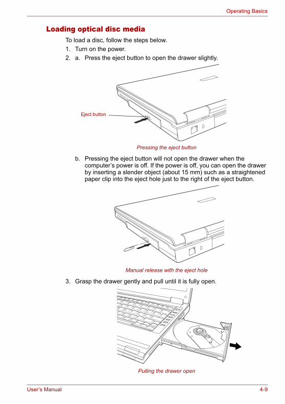
Operating Basics
Loading optical disc mediaTo load a disc, follow the steps below.1. Turn on the power.2. a. Press the eject button to open the drawer slightly.
Pressing the eject button
b. Pressing the eject button will not open the drawer when the computer’s power is off. If the power is off, you can open the drawer by inserting a slender object (about 15 mm) such as a straightened paper clip into the eject hole just to the right of the eject button.
Manual release with the eject hole
3. Grasp the drawer gently and pull until it is fully open.
Pulling the drawer open
Eject button
User’s Manual 4-9
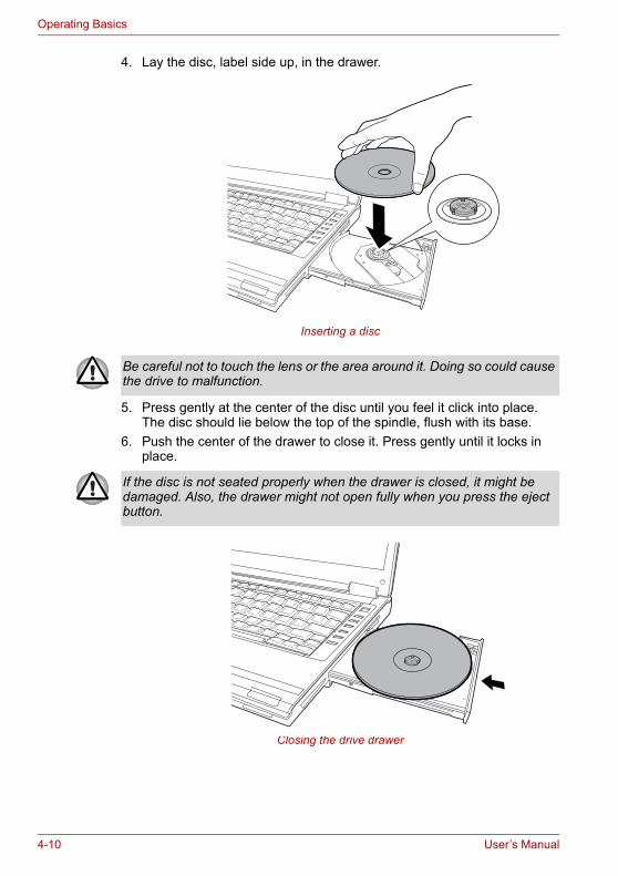
Operating Basics
4. Lay the disc, label side up, in the drawer.
Inserting a disc
5. Press gently at the center of the disc until you feel it click into place. The disc should lie below the top of the spindle, flush with its base.
6. Push the center of the drawer to close it. Press gently until it locks in place.
Closing the drive drawer
Be careful not to touch the lens or the area around it. Doing so could cause the drive to malfunction.
If the disc is not seated properly when the drawer is closed, it might be damaged. Also, the drawer might not open fully when you press the eject button.
4-10 User’s Manual
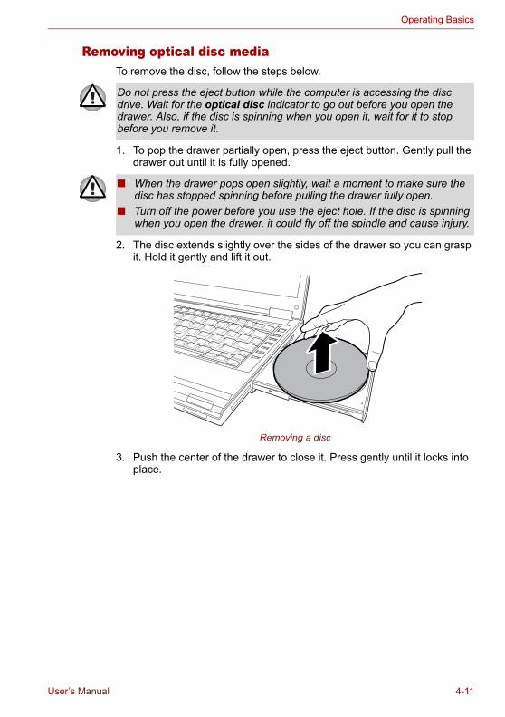
Operating Basics
Removing optical disc mediaTo remove the disc, follow the steps below.
1. To pop the drawer partially open, press the eject button. Gently pull the drawer out until it is fully opened.
2. The disc extends slightly over the sides of the drawer so you can grasp it. Hold it gently and lift it out.
Removing a disc
3. Push the center of the drawer to close it. Press gently until it locks into place.
Do not press the eject button while the computer is accessing the disc drive. Wait for the optical disc indicator to go out before you open the drawer. Also, if the disc is spinning when you open it, wait for it to stop before you remove it.
■ When the drawer pops open slightly, wait a moment to make sure the disc has stopped spinning before pulling the drawer fully open.
■ Turn off the power before you use the eject hole. If the disc is spinning when you open the drawer, it could fly off the spindle and cause injury.
User’s Manual 4-11
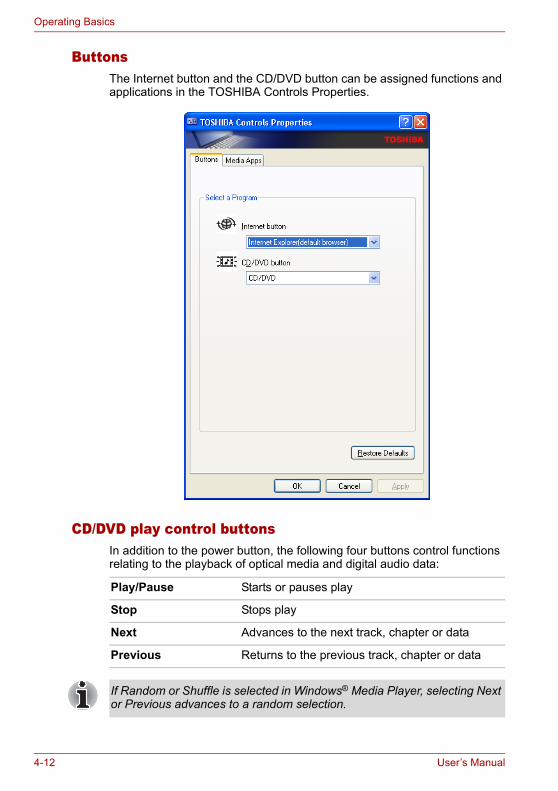
Operating Basics
ButtonsThe Internet button and the CD/DVD button can be assigned functions and applications in the TOSHIBA Controls Properties.
CD/DVD play control buttonsIn addition to the power button, the following four buttons control functions relating to the playback of optical media and digital audio data:
Play/Pause Starts or pauses play
Stop Stops play
Next Advances to the next track, chapter or data
Previous Returns to the previous track, chapter or data
If Random or Shuffle is selected in Windows® Media Player, selecting Next or Previous advances to a random selection.
4-12 User’s Manual
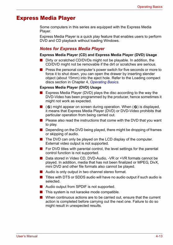
Operating Basics
Express Media PlayerSome computers in this series are equipped with the Express Media Player.Express Media Player is a quick play feature that enables users to perform DVD and CD playback without loading Windows.
Notes for Express Media PlayerExpress Media Player (CD) and Express Media Player (DVD) Usage■ Dirty or scratched CD/DVDs might not be playable. In addition, the
CD/DVD might not be removable if the dirt or scratches are serious. ■ Press the personal computer’s power switch for five seconds or more to
force it to shut down, you can open the drawer by inserting slender object (about 15mm) into the eject hole. Refer to the Loading compact discs section in Chapter 4, Operating Basics.
Express Media Player (DVD) Usage■ Express Media Player (DVD) plays the disc according to the way the
DVD-Video has been programmed by the producer, hence sometimes it might not work as expected.
■ ( ) might appear on screen during operation. When ( ) is displayed, it means that Express Media Player (DVD) or DVD-Video prohibits that particular operation from being carried out.
■ Please also read the instructions that come with the DVD that you want to play.
■ Depending on the DVD being played, there might be dropping of frames or skipping of audio.
■ The DVD can only be played on the LCD display of the computer. External video output is not supported.
■ For DVD titles with parental control, the level settings for the parental control function is not supported.
■ Data stored in Video CD, DVD-Audio, -VR or +VR formats cannot be played. In addition, media that has not been finalized or MPEG, DivX, mini DVD and other file formats also cannot be played.
■ Audio is only output in two channel stereo format.■ Titles with DTS or SDDS audio will have no audio output if such audio is
selected.■ Audio output from SPDIF is not supported.■ This system is not karaoke mode compatible.■ When continuous actions are to be carried out, ensure that the current
action is completed before carrying out the next one. Failure to do so might result in unexpected results.
User’s Manual 4-13
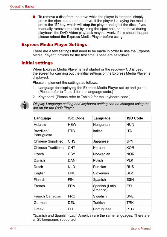
Operating Basics
■ To remove a disc from the drive while the player is stopped, simply press the eject button on the drive. If the player is playing the media, press the “E” key, which will stop the player and eject the disc. If you manually remove the disc by using the eject hole on the drive during playback, the DVD-Video playback may not work. If this should happen, please reboot the Express Media Player before using.
Express Media Player SettingsThere are a few settings that need to be made in order to use the Express Media Player functions for the first time. These are as follows:
Initial settingsWhen Express Media Player is first started or the recovery CD is used, the screen for carrying out the initial settings of the Express Media Player is displayed.Please implement the settings as follows:1. Language for displaying the Express Media Player set up and guide.
(Please refer to Table 1 for the language code.)2. Keyboard. (Please refer to Table 2 for the keyboard code.)
*Spanish and Spanish (Latin America) are the same languages. There are all 25 languages supported.
Display Language setting and keyboard setting can be changed using the set up for the DVD Player.
Language ISO Code Language ISO Code
Hebrew HEW Hungarian HUN
Brazilian/Portuguese
PTB Italian ITA
Chinese Simplified CHS Japanese JPN
Chinese Traditional CHT Korean KOR
Czech CSY Norwegian NOR
Danish DAN Polish PLK
Dutch NLD Russian RUS
English ENU Slovenian SLV
Finnish FIN Spanish ESN
French FRA Spanish (Latin America)
ESL
French Canadian FRC Swedish SVE
German DEU Turkish TRK
Greek ELL Portuguese PTG
4-14 User’s Manual
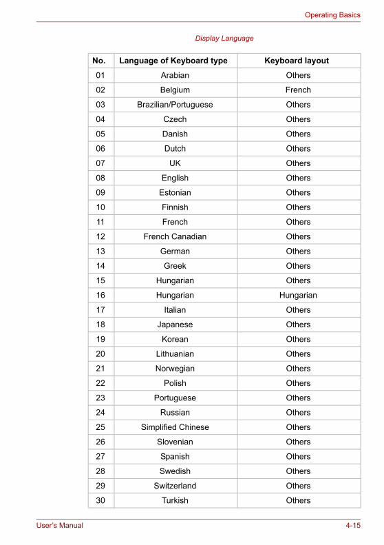
Operating Basics
Display Language
No. Language of Keyboard type Keyboard layout
01 Arabian Others
02 Belgium French
03 Brazilian/Portuguese Others
04 Czech Others
05 Danish Others
06 Dutch Others
07 UK Others
08 English Others
09 Estonian Others
10 Finnish Others
11 French Others
12 French Canadian Others
13 German Others
14 Greek Others
15 Hungarian Others
16 Hungarian Hungarian
17 Italian Others
18 Japanese Others
19 Korean Others
20 Lithuanian Others
21 Norwegian Others
22 Polish Others
23 Portuguese Others
24 Russian Others
25 Simplified Chinese Others
26 Slovenian Others
27 Spanish Others
28 Swedish Others
29 Switzerland Others
30 Turkish Others
User’s Manual 4-15
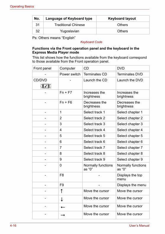
Operating Basics
Ps: Others means “English” Keyboard Code
Functions via the Front operation panel and the keyboard in the Express Media Player modeThis list shows how the functions available from the keyboard correspond to those available from the Front operation panel.
31 Traditional Chinese Others
32 Yugoslavian Others
Front panel Computer CD DVD
- Power switch Terminates CD Terminates DVD
CD/DVD - Launch the CD Launch the DVD
- Fn + F7 Increases the brightness
Increases the brightness
- Fn + F6 Decreases the brightness
Decreases the brightness
- 1 Select track 1 Select chapter 1
- 2 Select track 2 Select chapter 2
- 3 Select track 3 Select chapter 3
- 4 Select track 4 Select chapter 4
- 5 Select track 5 Select chapter 5
- 6 Select track 6 Select chapter 6
- 7 Select track 7 Select chapter 7
- 8 Select track 8 Select chapter 8
- 9 Select track 9 Select chapter 9
- 0 Normally functions as “0”
Normally functions as “0”
- F8 - Displays the top menu
- F9 - Displays the menu
- Move the cursor Move the cursor
- Move the cursor Move the cursor
- Move the cursor Move the cursor
- Move the cursor Move the cursor
No. Language of Keyboard type Keyboard layout
4-16 User’s Manual
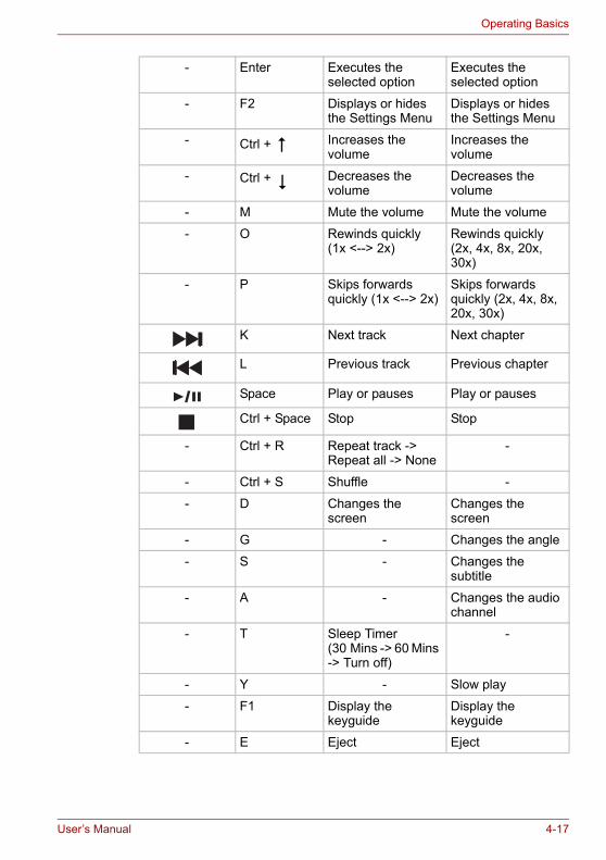
Operating Basics
- Enter Executes the selected option
Executes the selected option
- F2 Displays or hides the Settings Menu
Displays or hides the Settings Menu
- Ctrl + Increases the volume
Increases the volume
- Ctrl + Decreases the volume
Decreases the volume
- M Mute the volume Mute the volume
- O Rewinds quickly (1x <--> 2x)
Rewinds quickly (2x, 4x, 8x, 20x, 30x)
- P Skips forwards quickly (1x <--> 2x)
Skips forwards quickly (2x, 4x, 8x, 20x, 30x)
K Next track Next chapter
L Previous track Previous chapter
Space Play or pauses Play or pauses
Ctrl + Space Stop Stop
- Ctrl + R Repeat track -> Repeat all -> None
-
- Ctrl + S Shuffle -
- D Changes the screen
Changes the screen
- G - Changes the angle
- S - Changes the subtitle
- A - Changes the audio channel
- T Sleep Timer (30 Mins -> 60 Mins -> Turn off)
-
- Y - Slow play
- F1 Display the keyguide
Display the keyguide
- E Eject Eject
User’s Manual 4-17

Operating Basics
Writing CDs on a CD-RW/DVD-ROM driveYou can use the CD-RW/DVD-ROM drive to write data to CD-R/RW discs. The following applications for writing are preinstalled: Record Now!/DLA, licensed by Sonic Solutions.
Important messageBefore you write or rewrite to CD-R/RW media, read and follow all setup and operating instructions in this section. If you fail to do so, the CD-RW/DVD-ROM drive may not function properly, and you may fail to write or rewrite, lose data or incur other damage.
DisclaimerTOSHIBA does not bear responsibility for the following:■ Damage to any CD-R/-RW disc that may be caused by writing or
rewriting with this product.■ Any change or loss of the recorded contents of CD-R/-RW media that
may be caused by writing or rewriting with this product, or for any business profit loss or business interruption that may be caused by the change or loss of the recorded contents.
■ Damage that may be caused by using third party equipment or software.
Given the technological limitations of current optical disc writing drives, you may experience unexpected writing or rewriting errors due to disc quality or problems with hardware devices. Also, it is a good idea to make two or more copies of important data, in case of undesired change or loss of the recorded contents.
Before writing or rewritingPlease observe the following points when you write or rewrite the data.■ We recommend the following manufacturers of CD-R and CD-RW
media. Media quality can affect write or rewrite success rates.
CD-R discs can be written only once. CD-RW discs can be rewritten many times.
CD-R: TAIYOYUDEN CO., LTD.MITSUBISHI CHEMICAL CORPORATIONRICOH Co., Ltd.Hitachi Maxell Ltd.
CD-RW: MITSUBISHI CHEMICAL CORPORATIONRICOH Co., Ltd.
4-18 User’s Manual
Operating Basics
TOSHIBA has confirmed the operation of CD-R and CD-RW media of the manufacturers above. Operation of other media cannot be guaranteed.■ CD-RW can generally be rewritten about 1,000 times. However, the
actual number of rewrites is affected by the quality of the media and the way it is used.
■ Be sure to connect the universal AC adapter when you write or rewrite.■ Be sure to close all other software programs except the writing
software.■ Do not run software such as a screen saver which can put a heavy load
on the CPU.■ Operate the computer at full power. Do not use power-saving features.■ Do not write while virus check software is running. Wait for it to finish,
then disable virus detection programs including any software that checks files automatically in the background.
■ Do not use hard disk utilities, including those intended to enhance hard disk access speeds, as they may cause unstable operation and damage data.
■ Write from the computer’s hard disk drive to the CD. Do not try to write from shared devices such as a LAN server or any other network device.
■ Writing with software other than Sonic RecordNow! has not been confirmed. Therefore, operation with other software cannot be guaranteed.
When writing or rewritingNote the following when you write or rewrite a CD-R or CD-RW.■ Always copy data from the hard disk drive to the CD. Do not use
cut-and-paste as the original data will be lost if there is a write error.■ Do not perform any of the following actions:
■ Change users in the Windows XP operating system.■ Operate the computer for any other function, including the use of a
mouse or the Touch Pad, and the closing/opening of the LCD panel.■ Start a communication application, such as a modem.■ Apply impact or vibration to the PC.■ Install, remove or connect external devices such as PC Cards,
USB devices, an external display, i.LINK devices or optical digital devices.
■ Open the optical disc drive.■ If the media is poor in quality, dirty or damaged, writing or rewriting
errors may occur.■ Set the computer on a level surface and avoid places subject to
vibration, such as airplanes, trains, or cars. Do not use an unstable surface, such as a stand.
■ Keep mobile phones and other wireless communication devices away from the computer.
User’s Manual 4-19
Operating Basics
Writing CDs/DVDs on a DVD Super Multi drive supporting ±R Double Layer
You can use the DVD Super Multi drive supporting ±R Double Layer to write data to either CD-R/RW or DVD-R/-RW/+R/+RW/-RAM discs. The following applications for writing are preinstalled: Record Now!/DLA, licensed by Sonic Solutions. InterVideo WinDVD Creator 2 Platinum, which is a product of InterVideo, Inc.
Important messageBefore you write or rewrite to CD-R/RW or DVD-R/-RW/+R/+RW/-RAM media, read and follow all set-up and operating instructions in this section. If you fail to do so, the DVD Super Multi drive supporting ±R Double Layer may not function properly, and you may fail to write or rewrite, lose data or incur other damage.
DisclaimerTOSHIBA does not bear responsibility for the following:■ Damage to any CD-R/RW or DVD-R/-RW/+R/+RW/-RAM disc that may
be caused by writing or rewriting with this product.■ Any change or loss of the recorded contents of CD-R/RW or
DVD-R/-RW/ +R/+RW /-RAM media that may be caused by writing or rewriting with this product, or for any business profit loss or business interruption that may be caused by the change or loss of the recorded contents.
■ Damage that may be caused by using third party equipment or software.
Given the technological limitations of current optical disc writing drives, you may experience unexpected writing or rewriting errors due to disc quality or problems with hardware devices. Also, it is a good idea to make two or more copies of important data, in case of undesired change or loss of the recorded contents.
4-20 User’s Manual
Operating Basics
Before writing or rewritingPlease observe the following points when you write or rewrite data.■ Based on TOSHIBA’s limited compatibility testing, we suggest the
following manufacturers of CD-R/RW and DVD-R/+R/-RW/+RW/-RAM media. However, in no event does TOSHIBA guarantee the operation, quality or performance of any disc. Disc quality can affect write or rewrite success rates.
CD-R: TAIYOYUDEN CO., LTD.MITSUBISHI CHEMICAL CORPORATIONRICOH Co., Ltd.Hitachi Maxell Ltd.
CD-RW: MITSUBISHI CHEMICAL CORPORATIONRICOH Co., Ltd.
DVD-R: DVD Specifications for Recordable Disc for General Version 2.0TAIYOYUDEN CO., LTD.Matsushita Electric Industrial Co., Ltd.
DVD-RW: DVD Specifications for Re-recordable Disc for Version 1.1 or Version 1.2VICTOR COMPANY OF JAPAN, LIMITEDMITSUBISHI CHEMICAL CORPORATION
DVD+R: MITSUBISHI CHEMICAL CORPORATIONRICOH Co., Ltd.
DVD+RW: MITSUBISHI CHEMICAL CORPORATIONRICOH Co., Ltd.
*DVD-RAM: DVD Specifications for DVD-RAM Disc for Version 2.0, Version 2.1 or Version 2.2Matsushita Electric Industrial Co., Ltd.Hitachi Maxell Ltd.*DVD Multi drive and DVD Super Multi can use DVD-RAM.
DVD+R (DoubleLayer):
MITSUBISHI CHEMICAL CORPORATION
DVD-R (DoubleLayer):
MITSUBISHI CHEMICAL CORPORATION
User’s Manual 4-21
Operating Basics
■ If the disc is poor in quality, dirty or damaged, writing or rewriting errors may occur. Be careful to check the disc for dirt or damage before you use it.
■ The actual number of rewrites to CD-RW or DVD-RW/+RW/-RAM is affected by the quality of the disc and the way it is used.
■ There are two types of DVD-R: authoring and general use discs. Do not use authoring discs. Only general use discs can be written to by a computer drive.
■ You can use DVD-RAM discs that can be removed from a cartridge and DVD-RAM discs designed without a cartridge.
■ Other DVD-ROM drives for computers or other DVD players may not be able to read DVD-R/+R/-RW/+RW/-RAM discs.
■ Data written to a CD-R/DVD-R/+R disc cannot be deleted either in whole or in part.
■ Data deleted (erased) from a CD-RW and DVD-RW/+RW/-RAM disc cannot be recovered. Check the content of the disc carefully before you delete it. If multiple drives that can write data to discs are connected, be careful not to delete data from the wrong drive.
■ In writing to a DVD-R/+R/-RW/+RW disc, some disc space is required for file management, so you may not be able to write the full capacity of the disc.
■ Since the disc is based on the DVD-R/-RW standard, it will be filled with dummy data if the written data is less than about 1 GB. Even if you write only a small amount of data, it might take time to fill in the dummy data.
■ Two types of DVD-R/+R/-RW/+RW/-RAM discs are on the market: data and video. Use a video disc to store video data. You can use video discs on a DVD recorder as well as on your computer’s DVD-ROM drive. You cannot use data discs on a DVD recorder.
■ DVD-RAM formatted by FAT32 cannot be read in Windows 2000 without DVD-RAM Driver Software.
■ When multiple drives that can write data to discs are connected, be careful not to write to the wrong drive.
■ Be sure to connect the universal AC adapter before you write or rewrite.■ Before you enter standby/hibernation mode, be sure to finish DVD-RAM
writing. Writing is finished if you can eject DVD-RAM media.■ Be sure to close all other software programs except the writing
software.■ Do not run software such as a screen saver, which can put a heavy load
on the CPU.■ Operate the computer at full power. Do not use power-saving features.■ Do not write while virus check software is running. Wait for it to finish,
then disable virus detection programs including any software that checks files automatically in the background.
■ Do not use hard disk utilities, including those intended to enhance hard disk access speed, as they may cause unstable operation and damage data.
4-22 User’s Manual

Operating Basics
■ Write from the computer’s hard disk drive to the CD. Do not try to write from shared devices such as a LAN server or any other network device.
■ Writing with software other than Sonic RecordNow! or InterVideo WinDVD Creator 2 Platinum has not been confirmed. Therefore, operation with other software cannot be guaranteed.
When writing or rewritingPlease observe/consider the following when you write or rewrite to a CD-R/RW, DVD-R/-RW/-RAM or DVD+R/+RW disc.■ Do not perform any of the following actions when writing or rewriting:
■ Change users in the Windows XP operating system.■ Operate the computer for any other function, including using a
mouse or Touch Pad or closing/opening the LCD panel.■ Start a communication application such as a modem.■ Apply impact or vibration to the computer.■ Install, remove or connect external devices such as PC card, USB
devices, an external display, i.Link devices or optical digital devices.■ Use the audio/video control button to reproduce music or voice.■ Open the drive.
■ Do not use shut down/log off and standby/hibernation while writing or rewriting.
■ Make sure writing or rewriting is completed before going into standby/hibernation. Writing is completed if you can open the drive tray.
■ Set the computer on a level surface and avoid places subject to vibration such as airplanes, trains or cars. Do not use an unstable surface such as a stand.
■ Keep mobile phones and other wireless communication devices away from the computer.
■ Always copy data from the hard disk drive to the CD. Do not use cut-and-paste as the original data will be lost if there is a write error.
User’s Manual 4-23
Operating Basics
RecordNow! Basic for TOSHIBANote the following limitations when you use RecordNow!:■ DVD-Video cannot be created using RecordNow!■ DVD-Audio cannot be created using RecordNow!■ You cannot use the RecordNow! “Audio CD for Car or Home CD Player”
function to record music to the DVD-R/-RW or DVD+R/+RW media.■ Do not use the “Exact Copy” function of RecordNow! to copy
DVD-Video and DVD-ROM with copyright protection.■ DVD-RAM media cannot be backed up with the “Exact Copy” function
of RecordNow!■ You cannot back up a CD-ROM or CD-R/RW to DVD-R/-RW or
DVD+R/+RW using the “Exact Copy” function of RecordNow!.■ You cannot back up DVD-ROM, DVD-Video or DVD-R/-RW or
DVD+R/+RW to CD-R/RW using RecordNow!■ RecordNow! cannot record in packet format.■ You might not be able to use the “Exact Copy” function of RecordNow!
to backup a DVD-R/-RW or DVD+R/+RW disc that was made with other software on a different DVD-R/-RW or DVD+R/+RW recorder.
■ If you add data to a DVD-R and DVD+R disc that you have already recorded to, you might not be able to read the added data under some circumstances. It cannot be read in 16-bit operating systems, such as Windows 98SE and Windows ME, in Windows NT4 you will need Service Pack 6 or later to read the data, and in Windows 2000 you will need Service Pack 2 or later to read it. Some optical media drives cannot read added data regardless of the operating system.
■ RecordNow! does not support recording to DVD-RAM discs. To record to a DVD-RAM, use Explorer or other similar utility.
■ When you back up a DVD disc, be sure the source drive supports recording to DVD-R/-RW or DVD+R/+RW discs. If the source drive does not support recording to DVD-R/-RW or DVD+R/+RW discs, it might not be backed up correctly.
■ When you back up a DVD-R, DVD-RW, DVD+R or DVD+RW, be sure to use the same type of disc.
■ You cannot partially delete any data written to a CD-RW, DVD-RW or DVD+RW disc.
4-24 User’s Manual
Operating Basics
Data VerificationTo verify that data is written or rewritten correctly, follow the steps below before you write or rewrite a Data disc.
1. Click the Options button ( ) on the RecordNow! Console to open the Options panels.
2. Select the Data in the left-side menu.3. Mark the Verify data written to the disc after burning check box in the
Data Options.4. Click the OK button.
DLA for TOSHIBANote the following limitations when you use DLA:■ This software supports only rewritable discs (DVD+RW, DVD-RW, and
CD-RW). It does not support DVD+R, DVD-R, and CD-R discs that are not rewritable.
■ DLA does not support formatting a DVD-RAM disc and writing to it. They are performed by DVD-RAM Driver Software. If DLA Format menu may appear when inserting a DVD-RAM disc into the drive and right-clicking the drive icon in Windows Explorer, please use “DVDForm” to format this disc. You can run “DVDForm” by clicking the Start button on the taskbar to display the Start menu and then selecting “All Programs”, “DVD-RAM”, “DVD-RAM Driver” and “DVDForm” sequentially.
■ Do not use any discs that have been formatted with packet writing software other than DLA. Similarly, do not use any discs that have been formatted with DLA with any packet writing software other than DLA. When using a disc you are not familiar with, format it by selecting Full Format before using it.
■ Do not use the Cut & Paste function for files and folders. A file or folder that has been cut may be lost if writing fails due to an error on the disc.
■ When writing the Setup files for the program into a disc formatted by DLA and starting Setup from this disc, an error may occur. In this case, plase copy them to your hard disk and then run Setup.
User’s Manual 4-25

Operating Basics
When Using WinDVD Creator 2 Platinum You can record video back to your digital camcorder via i.LINK (IEEE1394) using WinDVD Creator Platinum. However, in some instances you may find that the playback sound is ’choppy’ - if this is the case perform the following steps:1. Click the Windows® Start button and select the Control Panel option.2. Click the Performance and Maintenance icon in the Control Panel.3. Click the System icon in the Performance and Maintenance window.4. Click the Advanced tab in the System Properties window.5. Click the Settings icon in the “Performance” section.6. Click the Advanced tab in the Performance Options window.7. Click the Change icon in the “virtual memory” section.8. Select the Custom size button in the Virtual Memory window.9. Specify much higher values for “Initial size” and “Maximum size”.10. Click the Set button in the Virtual Memory window.11. Click the OK button in the Virtual Memory window.
How to make a DVD-VideoSimplified steps for making a DVD-Video from video data captured from a DV-Camcorder:1. Click Start -> All Programs -> InterVideo WinDVD Creator2 ->
InterVideo WinDVD Creator to launch WinDVD Creator.2. Click the Capture button then capture the video data from the
DV-Camcorder via the IEEE1394 connection.3. Click the Edit button then drag the video clips from Video Library tab to
the edit track.4. Click the Make Movie button in the top bar.5. Double-click the right arrow button icon in the center of the right hand
side.6. Put a blank DVD-R/+R disc or an erased DVD-RW/+RW disc in the
drive.7. Click Start to record to the disc.8. When recording is finished, the tray opens.
How to learn more about InterVideo WinDVD CreatorPlease refer to the on-line Help for additional InterVideo WinDVD Creator information.
4-26 User’s Manual
Operating Basics
Important information for useNote the following limitations when you write video DVD:1. Editing digital video
■ Log in with Administrator rights to use WinDVD Creator.■ Make sure that your computer is running on AC power when using
WinDVD Creator.■ Operate the computer at Full Power. Do not use power-saving
features.■ While you are editing DVD, you can display previews. However, if
another application is running, the preview might not display properly.
■ WinDVD Creator cannot show video on an external monitor if the computer is configured for simultaneous display mode.
■ WinDVD Creator cannot edit or play copy protected content.■ Do not change display settings while using WinDVD Creator.■ Do not enter standby/hibernation mode while using WinDVD
Creator.■ Do not operate WinDVD Creator immediately after turning on the
computer, you should ensure you wait until all disc/disk drive activity has stopped.
■ When recording to a DV-Camcorder, to ensure you capture all of your data, let the camcorder record for a few seconds before you begin recording your actual data.
■ CD recorder, JPEG functions, DVD-Audio, mini DVD and Video CD functions are not supported in this version.
■ While recording video to DVD or tape, please close all other programs.
■ Do not run software like a screen saver because it can put a heavy load on the CPU.
■ Do not run communication applications like a modem or a LAN.
User’s Manual 4-27

Operating Basics
2. Before recording the video to DVD■ When you record to DVD media, please use only discs
recommended by the drive manufacturer.■ Do not set the working drive to be a slow device like a USB 1.1 hard
disk drive or it will fail to write the DVD.■ Do not perform any of the following actions:
■ Operate the computer for any other function, including using a mouse or Touch Pad or closing/opening the LCD panel.
■ Bump or cause vibration to the computer.■ Use either the mode button or the audio/video control buttons to
reproduce music or voice.■ Open the DVD drive.■ Install, remove or connect external devices such as PC card,
USB devices, an external display, i.LINK. devices or optical digital devices.
■ Please verify your disc after recording important data.■ DVD-R/+R/-RW discs cannot be written in VR format.■ A maximum of about 2 hours of video data can be written in DVD
Video format to DVD-R/+R/-RW/+RW discs.■ WinDVD Creator cannot export to DVD-Audio, VideoCD or miniDVD
formats.■ WinDVD Creator can write DVD-RAM/+RW in VR format, but the
disc may only play on your computer.■ When writing to a DVD disc, WinDVD Creator requires 2GB or more
of disk space for every one hour of video.■ When you make a fully recorded DVD, the chapter sequence may
not play correctly.3. About Disc Manager
■ WinDVD Creator can edit one play list on a disc.■ WinDVD Creator might show a different thumbnail than you
previously set in CE DVD-RAM recorder.■ Using the Disc Manager, you can edit DVD-VR format on DVD-RAM
media, DVD+VR format on DVD+RW media, and DVD-Video format on DVD-RW media.
4. About recorded DVDs■ Some DVD-ROM drives for personal computers or other DVD
players may not be able to read DVD-R/+R/-RW/+RW/-RAM discs.■ When playing your recorded disc on your computer, please use the
WinDVD software application.■ If you use an over-used rewritable disc, the full formatting might be
locked. Please use a brand new disc.
4-28 User’s Manual
Operating Basics
Media CareThis section provides tips on protecting data stored on your discs and disks.Handle your media with care. The following simple precautions will increase the lifetime of your media and protect the data stored on it:1. Store your discs in the container they came in to protect them and keep
them clean.2. Do not bend the disc.3. Do not write on, apply a sticker to, or otherwise mar the surface of the
disc that contains data.4. Hold the disc by its outside edge or the edge on the center hole.
Fingerprints on the surface can prevent the drive from properly reading data.
5. Do not expose to direct sunlight, or extreme heat or cold, and do not place heavy objects on your discs.
6. If your discs become dusty or dirty, wipe them with a clean dry cloth. Wipe from the center out, do not wipe in a circular direction around the disc. If necessary, use a cloth dampened in water or a neutral cleaner. Do not use benzine, thinner or similar cleaner.
Disks1. Store your disks in the container they came in to protect them and keep
them clean. If a disk is dirty, do not use cleaning fluid. Clean it with a soft damp cloth.
2. Do not slide back the disk’s protective metal covering or touch the disk’s magnetic surface. Fingerprints may prevent the disk drive from reading data from the disk.
3. Data may be lost if the disk is twisted, bent, or exposed to direct sunlight, or extreme heat or cold.
4. Do not place heavy objects on your disks.5. Do not eat, smoke, or use erasers near your disks. Foreign particles
inside the disk’s jacket can damage the magnetic surface.6. Magnetic energy can destroy data on disks. Keep your disks away from
speakers, radios, television sets and other sources of magnetic fields.
User’s Manual 4-29

Operating Basics
TV-OutUse the TV-Out port to connect to a television. Be sure to use a 4 pin type S-video cable. For more details, see Appendix B.
Setting up more than one displayYou can set up your computer to utilize more than one display, effectively spreading a single desktop screen across two monitors.The Display Properties window allows you to adjust more precisely the relative positioning of the two displays when they are configured as an extended desktop. On the Display Properties window, the two displays can be positioned horizontally, vertically or in any diagonal configuration you wish, as shown below.
TV Out Port
4-30 User’s Manual

Operating Basics
Cleaning the computerTo help ensure long, trouble-free operation, keep the computer free of dust and use care with liquids around the computer.■ Be careful not to spill liquids into the computer. If the computer does get
wet, turn the power off immediately and let the computer dry completely before you turn it on again.
■ Clean the computer using a slightly damp (with water) cloth. You can use glass cleaner on the display. Spray a small amount of cleaner on a soft, clean cloth and wipe the screen gently with the cloth.
Moving the computerThe computer is designed for rugged durability. However, a few simple precautions taken when moving the computer will help ensure trouble-free operation.■ Make sure all disk activity has ended before moving the computer.
Check the Built-in Hard Disk Drive and optical disc drive indicators on the computer.
■ If a disk is in the disk drive, remove it.■ If a disc is in the optical disc drive, remove it. Also make sure the optical
disc drive drawer is securely closed.■ Turn off the power to the computer.■ Disconnect all peripherals before moving the computer.■ Close the display. Do not pick up the computer by its display panel or
back (where the interface ports are located).■ Close all port covers.■ Disconnect the AC adapter if it is connected.■ Use the carrying case when transporting the computer.
If an external display will not be connected next time you use your computer, you should cancel any extended desktop or clone display settings before shutting down your computer.Clone display settings are those where more than one device has been selected and is simultaneously applicable.
Never spray cleaner directly onto the computer or let liquid run into any part of it. Never use harsh or caustic chemical products to clean the computer.
User’s Manual 4-31

Operating Basics
4-32 User’s Manual
Chapter 5
The Keyboard
The computer’s keyboard layouts are compatible with a 101/102-key enhanced keyboard. By pressing some keys in combination, all the 101/102-key keyboard functions can be executed on the computer.The number of keys on your keyboard depends on which country/region’s keyboard layout your computer is configured with. Keyboards for numerous languages are available.There are five types of keys: typewriter keys, keypad overlay, function keys, soft keys and cursor control keys. The typewriter keys and keypad overlay keys are gray. The other keys are dark gray.
Typewriter keysThe typewriter keys, produce the upper- and lower-case letters, numbers, punctuation marks, and special symbols that appear on the screen.There are some differences, however, between using a typewriter and using a computer keyboard:■ Letters and numbers produced in computer text vary in width. Spaces,
which are created by a space character may also vary depending on line justification and other factors.
■ The lowercase l (el) and the number 1 (one) are not interchangeable on computers as they are on a typewriter.
■ The uppercase O (oh) and the 0 (zero) are not interchangeable.■ The Caps Lock function key locks only the alphabetic characters in
uppercase while the shift lock on a typewriter places all keys in the shifted position.
■ The Shift keys, the Tab key, and the BkSp (backspace) key perform the same function as their typewriter counterparts but also have special computer functions.
User’s Manual 5-1
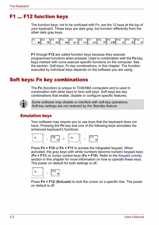
The Keyboard
F1 ... F12 function keysThe function keys, not to be confused with Fn, are the 12 keys at the top of your keyboard. These keys are dark gray, but function differently from the other dark gray keys.
F1 through F12 are called function keys because they execute programmed functions when pressed. Used in combination with the Fn key, keys marked with icons execute specific functions on the computer. See the section, Soft keys: Fn key combinations, in this chapter. The function executed by individual keys depends on the software you are using.
Soft keys: Fn key combinationsThe Fn (function) is unique to TOSHIBA computers and is used in combination with other keys to form soft keys. Soft keys are key combinations that enable, disable or configure specific features.
Emulation keysYour software may require you to use keys that the keyboard does not have. Pressing the Fn key and one of the following keys simulates the enhanced keyboard’s functions.
Press Fn + F10 or Fn + F11 to access the integrated keypad. When activated, the gray keys with white numbers become numeric keypad keys (Fn + F11) or cursor control keys (Fn + F10). Refer to the Keypad overlay section in this chapter for more information on how to operate these keys. The power on default for both settings is off.
Press Fn + F12 (ScrLock) to lock the cursor on a specific line. The power on default is off.
Some software may disable or interfere with soft-key operations. Soft-key settings are not restored by the Standby feature.
5-2 User’s Manual
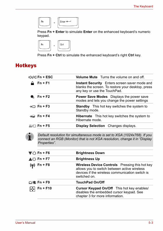
The Keyboard
Press Fn + Enter to simulate Enter on the enhanced keyboard’s numeric keypad.
Press Fn + Ctrl to simulate the enhanced keyboard’s right Ctrl key.
Hotkeys
Fn + ESC Volume Mute Turns the volume on and off.
Fn + F1 Instant Security Enters screen saver mode and blanks the screen. To restore your desktop, press any key or use the TouchPad.
Fn + F2 Power Save Modes Displays the power save modes and lets you change the power settings
Fn + F3 Standby This hot key switches the system to Standby mode.
Fn + F4 Hibernate This hot key switches the system to Hibernate mode.
Fn + F5 Display Selection Changes displays.
Default resolution for simultaneous mode is set to XGA (1024x768). If you connect an RGB (Monitor) that is not XGA resolution, change it in “Display Properties”.
Fn + F6 Brightness DownFn + F7 Brightness UpFn + F8 Wireless Device Controls Pressing this hot key
allows you to switch between active wireless devices if the wireless communication switch is switched on.
Fn + F9 TouchPad On/OffFn + F10 Cursor Keypad On/Off This hot key enables/
disables the embedded cursor keypad. See chapter 3 for more information.
User’s Manual 5-3
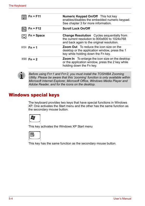
The Keyboard
Windows special keysThe keyboard provides two keys that have special functions in Windows XP. One activates the Start menu and the other has the same function as the secondary mouse button.
This key activates the Windows XP Start menu
This key has the same function as the secondary mouse button.
Fn + F11 Numeric Keypad On/Off This hot key enables/disables the embedded numeric keypad. See chapter 3 for more information.
Fn + F12 Scroll Lock On/Off
Fn + Space Change Resolution Cycles sequentially from the current resolution to 800x600 to 1024x768 and back again to the original resolution.
Fn + 1 Zoom Out To reduce the icon size on the desktop or the application window, press the 1 key while holding down the Fn key.
Fn + 2 Zoom In To enlarge the icon size on the desktop or the application window, press the 2 key while holding down the Fn key.
Before using Fn+1 and Fn+2, you must install the TOSHIBA Zooming Utility. Please be aware that this ’zooming’ function is only available within Microsoft Internet Explorer, Microsoft Office, Windows Media Player and Adobe Reader, and for the icons on the desktop.
5-4 User’s Manual
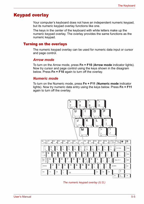
The Keyboard
Keypad overlayYour computer’s keyboard does not have an independent numeric keypad, but its numeric keypad overlay functions like one.The keys in the center of the keyboard with white letters make up the numeric keypad overlay. The overlay provides the same functions as the numeric keypad.
Turning on the overlaysThe numeric keypad overlay can be used for numeric data input or cursor and page control.
Arrow modeTo turn on the Arrow mode, press Fn + F10 (Arrow mode indicator lights). Now try cursor and page control using the keys shown in the disagram below. Press Fn + F10 again to turn off the overlay.
Numeric modeTo turn on the Numeric mode, press Fn + F11 (Numeric mode indicator lights). Now try numeric data entry using the keys below. Press Fn + F11 again to turn off the overlay.
The numeric keypad overlay (U.S.)
User’s Manual 5-5
The Keyboard
Temporarily using normal keyboard (overlay on)While using the overlay, you can temporarily access the normal keyboard without turning off the overlay:1. Hold down Fn and press any other key. All keys will operate as if the
overlay were off.2. Type upper-case characters by holding down Fn + Shift and pressing a
character key.3. Release Fn to continue using the overlay.
Temporarily using overlay (overlay off)While using the normal keyboard, you can temporarily use the keypad overlay without turning it on:1. Press and hold down Fn.2. Check the keyboard indicators. Pressing Fn turns on the most recently
used overlay. If the Numeric mode indicator lights, you can use the overlay for numeric entry. If the Arrow mode indicator lights, you can use it for cursor and page control.
3. Release Fn to return to normal keyboard operation.
Temporarily changing modesIf the computer is in Numeric mode, you can switch temporarily to Arrow mode by pressing a shift key.If the computer is in Arrow mode, you can switch temporarily to Numeric mode by pressing a shift key.
Generating ASCII charactersNot all ASCII characters can be generated using normal keyboard operation. But, you can generate these characters using their ASCII codes.With the overlay on:1. Hold down Alt.2. Using the overlay keys, type the ASCII code.3. Release Alt, and the ASCII character appears on the display screen.With the overlay off:1. Hold Alt + Fn.2. Using the overlay keys, type the ASCII code.3. Release Alt + Fn, and the ASCII character appears on the display
screen.
5-6 User’s Manual
Chapter 6
Power and Power-Up Modes
The computer’s power resources include the AC adapter and internal batteries. This chapter gives details on making the most effective use of these resources including charging and changing batteries, tips for saving battery power, and power up modes.
Power conditionsThe computer’s operating capability and battery charge status are affected by the power conditions: whether an AC adapter is connected, whether a battery is installed and what the charge level is for the battery.
Power on Power off (no operation)
AC adapter connected
Battery fully charged
• Operates• No charge• LED: Battery green or blue
DC IN green or blue
• No charge• LED: Battery green or blue
DC IN green or blue
Battery partially charged
• Operates• Charge• LED: Battery Amber
DC IN green or blue
• Charge• LED: Battery Amber
DC IN green or blue
No battery installed or no charge
• Operates • No charge• LED: Battery off
DC IN green or blue
• No charge• LED: Battery off
DC IN green or blue
LED color (green or blue) is dependent on the model you purchased.
User’s Manual 6-1
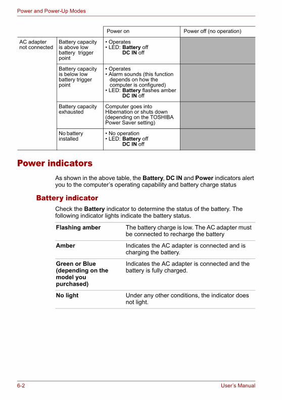
Power and Power-Up Modes
Power indicatorsAs shown in the above table, the Battery, DC IN and Power indicators alert you to the computer’s operating capability and battery charge status
Battery indicatorCheck the Battery indicator to determine the status of the battery. The following indicator lights indicate the battery status.
AC adapter not connected
Battery capacity is above low battery trigger point
• Operates• LED: Battery off
DC IN off
Battery capacity is below low battery trigger point
• Operates• Alarm sounds (this function
depends on how the computer is configured)
• LED: Battery flashes amberDC IN off
Battery capacity exhausted
Computer goes into Hibernation or shuts down (depending on the TOSHIBA Power Saver setting)
No battery installed
• No operation• LED: Battery off
DC IN off
Power on Power off (no operation)
Flashing amber The battery charge is low. The AC adapter must be connected to recharge the battery
Amber Indicates the AC adapter is connected and is charging the battery.
Green or Blue (depending on the model you purchased)
Indicates the AC adapter is connected and the battery is fully charged.
No light Under any other conditions, the indicator does not light.
6-2 User’s Manual

Power and Power-Up Modes
DC IN indicatorCheck the DC IN indicator to determine the power status with the AC adapter connected:
Power indicatorCheck the Power indicator to determine the power status with the AC adapter connected:
Battery typesThe computer has two types of batteries:■ Battery pack■ Real Time Clock (RTC) battery
Battery packWhen the AC adapter is not connected, the computer’s main power source is a removable lithium ion battery pack, also referred to in this manual as the battery.You can purchase additional battery packs for extended use of the computer away from an AC power source.The battery is a disposable item. When its operation becomes short even when fully charged, replace it with a new one.
Green or Blue (depending on the model you purchased)
Indicates the AC adapter is connected and is correctly supplying power to the computer.
No light Indicates the AC adapter is not connected.
Green or Blue (depending on the model you purchased)
Indicates power is being supplied and the computer is turned on.Power indicator is located inside of the Power Button (depending the model you purchased) and in the front of the computer.
Blinking amber Indicates power is being supplied to the computer while the computer is in Standby mode.
No light Under any other conditions, the indicator does not light.
User’s Manual 6-3
Power and Power-Up Modes
Real Time Clock batteryThe Real Time Clock (RTC) battery provides power for the internal real time clock and calendar. It also maintains the system configuration.If the RTC battery becomes completely discharged, the system loses this data and the real time clock and calendar stop working. The following message appears when you turn on the power:
When this error appears, the following action is recommended.1. Connect the AC adapter and let the battery charge for 24-hours.2. Press F2 to enter BIOS setup menu.3. Set correct time and date.
■ The battery pack is a lithium ion battery, which can explode if not properly replaced, used, handled or disposed of. Dispose of the battery as required by local ordinances or regulations. Use only batteries recommended by TOSHIBA as replacements.
■ Do not remove the battery pack while the computer is in Standby Mode. In this mode data is stored in memory, so if the computer loses power, it will be lost.
■ Battery type (depending on the model you purchased): 6 cell-PA3465U-1BRS,PA3465U-1BAS 8 cell-PA3457U-1BRS,PA3457U-1BAS
ERROR 0271: Check date and time settings.WARNING 0251: System CMOS checksum bad - Default configuration used.Press <F1> to resume, <F2> to Setup.
The computer’s RTC battery is a lithium battery and should be replaced only by your dealer or by a TOSHIBA service representative. The battery can explode if not properly replaced, used, handled or disposed of. Dispose of the battery as required by local ordinances or regulations.
If you still see the error message after performing the above actions, please contact your TOSHIBA service representative.
6-4 User’s Manual
Power and Power-Up Modes
Care and use of the battery packThe battery pack is a vital component of portable computing. Taking proper care of it will help ensure longer operating time on battery power as well as a longer life for your battery pack. Follow the instructions in this section carefully to ensure safe operation and maximum performance.
Safety precautionsMishandling of batteries can cause death, serious injury or property damage.Carefully observe the following advisories:Danger: Indicates an imminently hazardous situation, which could result in death or serious injury, if you do not follow instructions.Warning: Indicates a potentially hazardous situation, which could result in death or serious injury, if you do not follow instructions.Caution: Indicates a potentially hazardous situation, which if not avoided, may result in moderate or minor injury or property damage.Note: Provides important information.
Danger1. Never try to dispose of the battery pack by burning or expose it to a
heating device such as a microwave oven. The battery pack could explode and cause bodily injury.
2. Never try to disassemble, repair or otherwise tamper with a battery pack. The battery pack will overheat and ignite. Leakage of caustic alkaline solution or other electrolytic substances will cause fire or injury, possibly resulting in death or serious injury.
3. Never short-circuit the battery pack by contacting the terminals with a metal object. A short-circuit can cause fire or otherwise damage the battery pack and possibly cause injury. To avoid accidental short-circuit, always wrap the battery pack in plastic and cover the terminals with electrical tape when storing or disposing of the battery pack.
4. Never puncture the battery pack with a nail or other sharp object. Never strike it with a hammer or other object. Never step on it.
5. Never try to charge the battery pack in any manner other than that described in the user’s manual. Never connect the battery pack to a plug socket or to an automobile’s cigarette lighter socket. It may rupture or ignite.
6. Use only the battery pack supplied with the computer or other device or an battery pack approved by the computer or device’s manufacturer. Battery packs have different voltages and terminal polarities. Use of an improper battery could cause smoke, fire or rupture of the battery pack.
7. Never subject a battery pack to heat, such as storage near a heat source. Exposure to heat can cause the battery pack to ignite, explode or leak caustic liquid and cause death or serious injury. It could also fail or malfunction causing data loss.
User’s Manual 6-5
Power and Power-Up Modes
8. Never expose the battery pack to abnormal shock, vibration or pressure. The battery pack’s internal protective device will fail, causing it to overheat, explode, ignite or leak caustic liquids possibly resulting in death or serious injury.
9. Never let a battery pack become wet. A wet battery pack will overheat, ignite or rupture possibly resulting in death or serious injury.
Warning1. Never allow caustic electrolyte fluid leaked from a battery pack to
contact your eyes, skin or clothing. If caustic electrolyte fluid should contact your eyes, immediately wash your eyes with large amounts of running water and seek medical attention, to help prevent eye damage. It electrolyte fluid should contact your skin, immediately wash it under running water to prevent rash. If it contacts your clothes, promptly remove them to prevent the fluid from contacting your skin or eyes.
2. Immediately turn off the power, disconnect the AC adapter and remove the battery if any of the following events are observed in the battery pack: offensive or unusual odor, excessive heat, discoloration or deformation. Never use the computer again until it has been checked by a TOSHIBA service provider. It might generate smoke or fire, or the battery pack might rupture.
3. Make sure the battery is securely installed in the computer before attempting to charge the battery pack. Improper installation could generate smoke or fire, or cause the battery pack to rupture.
4. Keep the battery pack out or reach of infants and children. It can cause injury.
Caution1. Never continue to use a battery pack after its recharging capacity has
become impaired, or after the display of a warning message indicating that the battery pack’s power is exhausted. Continued use of an exhausted or impaired battery pack could cause the loss of data.
2. Never dispose of battery packs with normal trash. Bring them to your TOSHIBA dealer or to another recycling center to save resources and prevent environmental damage. Cover the terminals with electrical tape to prevent short-circuits, which could cause the battery pack to ignite or rupture.
3. Use only battery packs recommended by TOSHIBA as replacements.4. Always make sure the battery pack is installed correctly and securely.
Otherwise, a battery pack could fall out and possibly cause injury.5. Charge the battery pack only in an ambient temperature between 5 and
30 degrees Celsius. Otherwise, the electrolyte solution might leak, battery pack performance might deteriorate and the battery life might be shortened.
6-6 User’s Manual
Power and Power-Up Modes
6. Be sure to monitor the remaining battery power. If the battery pack or real time clock battery discharge completely, Standby Mode will not function, and data in memory will be lost, and the computer might register an incorrect time and date. In this case, connect the AC adapter to recharge the batteries.
7. Never install or remove the battery pack without first turning off the power and disconnecting the AC adapter. Never remove the battery pack while the computer is in Standby Mode as data will be lost.
Note1. Never remove the battery pack while the Wake-up on LAN function is
enabled. Data will be lost. Before you remove a battery pack, disable the Wake-up on LAN function.
2. To ensure the battery pack maintains maximum capacity, operate the computer on battery power once a week until the battery pack is fully discharged. Refer to the section Extending battery life in this chapter for procedures. If the computer is continuously operated on AC power for an extended period, more than a week, the battery might fail to retain a charge. It might not function efficiently over the expected life of the battery pack and the Battery indicator might not indicate a low-battery condition.
3. After the battery pack is charged, avoid leaving the AC adapter connected and the computer turned off for more than a few hours at a time. Continuing to charge a fully charged battery pack can damage the battery.
Charging the batteriesWhen the power in the battery pack becomes low, the Battery indicator flashes amber indicating that only a few minutes of battery power remain. If you continue to use the computer while the Battery indicator flashes, the computer enables Hibernation mode (so you don’t lose data) and automatically turns off.You must recharge a battery pack when it becomes discharged.
ProceduresTo recharge a battery pack while it is installed in the computer, connect the AC adapter to the DC IN socket and plug the other end into a working outlet.The Battery indicator glows amber when the battery is being charged.
TimeThe following table shows the time required to fully charge a discharged battery.
Use only the computer connected to an AC power source to charge the battery pack. Do not attempt to charge the battery pack with any other charger.
User’s Manual 6-7

Power and Power-Up Modes
Charging time (hours)
Battery charging noticeThe battery may not charge right away under the following conditions:■ The battery is extremely hot or cold. To make sure the battery charges
to its full capacity, charge the battery at room temperature of 10° to 30°C (50° to 86°F).
■ The battery is nearly completely discharged. Leave the AC adapter connected for a few minutes and the battery should begin charging.
The Battery indicator may show a rapid decrease in battery operating time when you try to charge a battery under the following conditions:■ The battery has not been used for a long time.■ The battery has completely discharged and been left in the computer for
a long time.■ A cool battery is installed in a warm computer.In such case, follow the steps below.1. Fully discharge the battery by leaving it in the computer with the power
on until the power automatically shuts off.2. Plug in the AC adapter.3. Charge the battery until the Battery indicator glows green or blue
(depending the model you purchased).Repeat these steps two or three times until the battery recovers normal capacity.
Battery type Power on Power off
Battery pack about 12 or longer about 3 or longer
RTC battery about 24 about 24 with AC or Battery pack
The charging time when the computer is on is affected by ambient temperature, the temperature of the computer and how you use the computer.If you make heavy use of external devices the battery might scarcely charge at all during operation. Refer also to the section Maximizing battery operating time.
Once a battery pack is fully charged, it is recommended that you operate the computer only on battery power until the battery pack completely discharges. Doing so extends battery life and helps ensure accurate monitoring of battery capacity.
Leaving the AC adapter connected will shorten battery life. At least once a week, run the computer on battery power until the battery is fully discharged, then recharge the battery.
6-8 User’s Manual
Power and Power-Up Modes
Monitoring battery capacityRemaining battery power can be monitored by the TOSHIBA Power Saver. Refer to Utilities in Chapter 1, Introduction.
Maximizing battery operating timeA battery’s usefulness depends on how long it can supply power on a single charge.How long the charge lasts in a battery depends on:■ How you configure the computer (for example, whether you enable
battery power saving options). The computer provides a battery save mode to conserve battery power. This mode has the following options:■ Display auto off■ Hard Disk Drive auto off■ System auto off■ LCD brightness
■ How often and how long you use the hard disk, optical media drive and the disk drive (if one is connected).
■ How much charge the battery contained to begin with.■ How you use optional devices, such as a PC Card, to which the battery
supplies power.■ Enabling Standby Mode or Hibernation Mode conserves battery power
if you are frequently turning the computer off and on.■ Where you store your programs and data.■ Closing the display when you are not using the keyboard saves power.■ Operating time decreases at low temperatures.■ The condition of the battery terminals. Make sure the battery terminals
stay clean by wiping them with a clean dry cloth before installing the battery pack.
■ Wait for a moment after turning on the computer before trying to monitor the remaining operating time. The computer needs this time to check the battery’s remaining capacity.
■ With repeated discharges and recharges, the battery’s capacity will gradually decrease. Therefore, an often used, older battery will not operate for as long as a new battery even when both are fully charged.
User’s Manual 6-9
Power and Power-Up Modes
Retaining data with power off (standby mode)When you turn off your computer with fully charged batteries, the batteries retain data/charge for the following approximate time periods:
Extending battery lifeTo maximize the life of your battery pack:■ If you have extra battery packs, rotate their use.■ If you will not be using the system for an extended period, remove the
battery pack.■ Store spare battery packs in a cool dry place out of direct sunlight.
Replacing the battery packWhen the battery pack reaches the end of its operating life you will need to install a new one. If the Battery indicator flashes amber shortly after the battery has been fully recharged, the battery pack needs to be replaced.You might also replace a discharged battery pack with a charged spare when you are operating your computer away from an AC power source. This section explains how to remove and install the battery pack.
Removing the battery packTo replace a discharged battery pack, follow the steps below.
1. Save your work.2. Turn the computer’s power off. Make sure the Power indicator is off.3. Remove all cables connected to the computer.4. Turn the computer upside down.5. Unlock the Battery Pack Lock.
Battery Approximately 1.5 days (Standby mode, 8-cell)Approximately 1 day (Standby mode, 6-cell)Approximately 0.75 day (Standby mode, 4-cell)Approximately 1 month (Shut down mode, all type of battery packs)
RTC battery Approximately 1 month
■ When handling battery packs, be careful not to short circuit the terminals. Also do not drop, hit or otherwise apply impact; do not scratch or break the casing and do not twist or bend the battery pack.
■ Do not remove the battery pack while the computer is in Standby Mode as data in memory will be lost.
6-10 User’s Manual
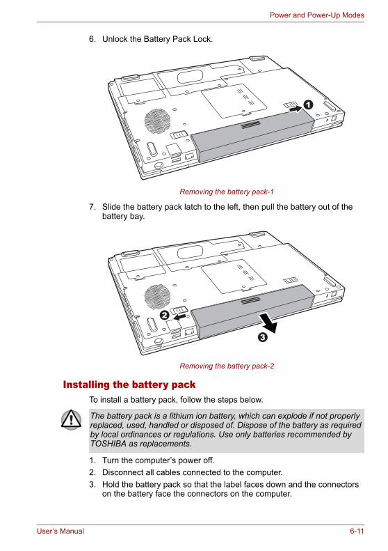
Power and Power-Up Modes
6. Unlock the Battery Pack Lock.
Removing the battery pack-1
7. Slide the battery pack latch to the left, then pull the battery out of the battery bay.
Removing the battery pack-2
Installing the battery packTo install a battery pack, follow the steps below.
1. Turn the computer’s power off.2. Disconnect all cables connected to the computer.3. Hold the battery pack so that the label faces down and the connectors
on the battery face the connectors on the computer.
1
3
2
The battery pack is a lithium ion battery, which can explode if not properly replaced, used, handled or disposed of. Dispose of the battery as required by local ordinances or regulations. Use only batteries recommended by TOSHIBA as replacements.
User’s Manual 6-11
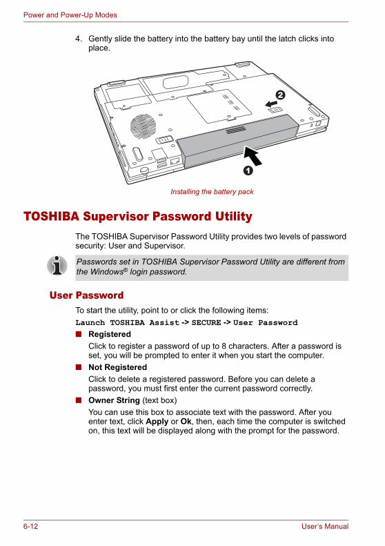
Power and Power-Up Modes
4. Gently slide the battery into the battery bay until the latch clicks into place.
Installing the battery pack
TOSHIBA Supervisor Password UtilityThe TOSHIBA Supervisor Password Utility provides two levels of password security: User and Supervisor.
User PasswordTo start the utility, point to or click the following items:Launch TOSHIBA Assist -> SECURE -> User Password ■ Registered
Click to register a password of up to 8 characters. After a password is set, you will be prompted to enter it when you start the computer.
■ Not RegisteredClick to delete a registered password. Before you can delete a password, you must first enter the current password correctly.
■ Owner String (text box)You can use this box to associate text with the password. After you enter text, click Apply or Ok, then, each time the computer is switched on, this text will be displayed along with the prompt for the password.
1
2
Passwords set in TOSHIBA Supervisor Password Utility are different from the Windows® login password.
6-12 User’s Manual
Power and Power-Up Modes
Supervisor passwordIf you set a supervisor password, some functions will be restricted when a user logs on with the user password. To set a supervisor password:TOSHIBA Assist -> SECURE -> Supervisor passwordThis utility lets you do the following:■ Register or delete the supervisor password.■ Specify restrictions for general users.
Starting the computer by passwordIf you registered a password, start the computer by entering the password manually.
To enter a password manually, follow these steps:1. Turn on the power as described in Chapter 3, Getting Started.
The following message will appear in the LCD:Enter Password [xxxxxxxx]
2. Enter the Password.3. Press Enter.
Power-up modesThe computer has three power-up modes:■ Hibernation (saves data in memory to the hard disk)■ Standby (power remains on, maintaining the data in memory, but the
CPU and all other devices effectively enter a ’sleep’ mode)■ Boot (does not save data in memory)
The password is necessary only if the computer was shut down in boot mode, not in Hibernation or Standby mode.
If you enter the password incorrectly three consecutive times, the computer shuts down. You must turn on the computer again and re-enter the password.
Refer also to the section Turning off the power in Chapter 3, Getting Started.
User’s Manual 6-13
Power and Power-Up Modes
Panel power off/onThis feature makes the computer to enter Hibernation when the display panel is closed and turns it back on when the display panel is opened.
System automatic Standby/HibernationThis feature automatically turns off the system in Standby or Hibernation mode if the computer is not used for a set duration.Refer to Special features, in Chapter 1, Introduction for an explanation of how to set the duration.
If the panel power off function is enabled and you use Shut down Windows, do not close the display until the shut down function is completed.
6-14 User’s Manual
Chapter 7
HW Setup
This chapter explains how to use the TOSHIBA HW Setup utility to configure your computer. TOSHIBA HW Setup lets you configure settings for various hardware devices through a number of tabs titled General, Password, Display, Boot Priority, Keyboard, CPU, LAN, and USB.
Accessing HW SetupTo run HW Setup, click Start, click Control Panel, click Printers and Other Hardware and select TOSHIBA HW Setup.
HW Setup WindowThe HW Setup window contains the following tabs: General, Password, Display, Boot Priority, Keyboard, CPU, LAN, and USB.There are also these three buttons:
Some models are not equipped with the CPU tab.
OK Accepts your changes and closes the HW Setup window.
Cancel Closes the window without accepting your changes.
Apply Accepts all your changes without closing the HW Setup window.
User’s Manual 7-1
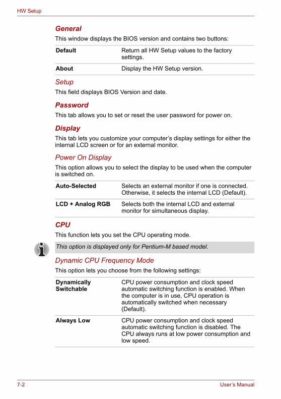
HW Setup
General This window displays the BIOS version and contains two buttons:
SetupThis field displays BIOS Version and date.
PasswordThis tab allows you to set or reset the user password for power on.
DisplayThis tab lets you customize your computer’s display settings for either the internal LCD screen or for an external monitor.
Power On DisplayThis option allows you to select the display to be used when the computer is switched on.
CPUThis function lets you set the CPU operating mode.
Dynamic CPU Frequency ModeThis option lets you choose from the following settings:
Default Return all HW Setup values to the factory settings.
About Display the HW Setup version.
Auto-Selected Selects an external monitor if one is connected. Otherwise, it selects the internal LCD (Default).
LCD + Analog RGB Selects both the internal LCD and external monitor for simultaneous display.
This option is displayed only for Pentium-M based model.
Dynamically Switchable
CPU power consumption and clock speed automatic switching function is enabled. When the computer is in use, CPU operation is automatically switched when necessary (Default).
Always Low CPU power consumption and clock speed automatic switching function is disabled. The CPU always runs at low power consumption and low speed.
7-2 User’s Manual
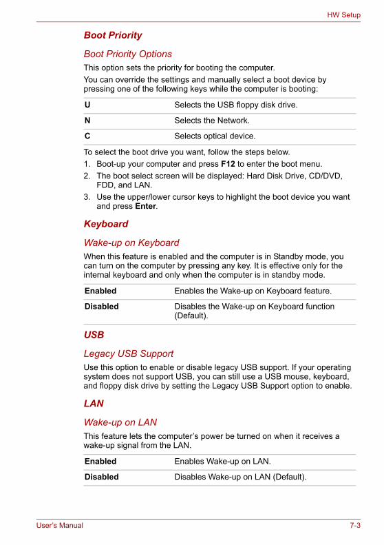
HW Setup
Boot Priority
Boot Priority OptionsThis option sets the priority for booting the computer. You can override the settings and manually select a boot device by pressing one of the following keys while the computer is booting:
To select the boot drive you want, follow the steps below.1. Boot-up your computer and press F12 to enter the boot menu. 2. The boot select screen will be displayed: Hard Disk Drive, CD/DVD,
FDD, and LAN.3. Use the upper/lower cursor keys to highlight the boot device you want
and press Enter.
Keyboard
Wake-up on KeyboardWhen this feature is enabled and the computer is in Standby mode, you can turn on the computer by pressing any key. It is effective only for the internal keyboard and only when the computer is in standby mode.
USB
Legacy USB SupportUse this option to enable or disable legacy USB support. If your operating system does not support USB, you can still use a USB mouse, keyboard, and floppy disk drive by setting the Legacy USB Support option to enable.
LAN
Wake-up on LANThis feature lets the computer’s power be turned on when it receives a wake-up signal from the LAN.
U Selects the USB floppy disk drive.
N Selects the Network.
C Selects optical device.
Enabled Enables the Wake-up on Keyboard feature.
Disabled Disables the Wake-up on Keyboard function (Default).
Enabled Enables Wake-up on LAN.
Disabled Disables Wake-up on LAN (Default).
User’s Manual 7-3

HW Setup
Built-in LANThis feature enables or disables the Built-in LAN.
The Wake-up on LAN function consumes power even when the system is off. Leave the AC adaptor connected while using this feature.
Do not install or remove an optional memory module while Wake-up on LAN is enabled.
Enabled Enables Built-in LAN function (Default).
Disabled Disables Built-in LAN function.
7-4 User’s Manual

Chapter 8
Optional Devices
Optional devices can expand the computer’s capabilities and its versatility. This chapter describes connection or installation of the following types of devices, which are available from your TOSHIBA dealer:
Cards/Memory■ PC card■ Express Card■ SD (Secure Digital) / MMC (MultiMediaCard) / MS (Memory Stick) /
MS Pro (Memory Stick Pro) / xD (xD-Picture Card) cards■ Memory modules
Power devices■ Battery pack■ AC adapter
Peripheral devices■ External monitor■ Television■ i.LINK (IEEE1394)■ Security lock
User’s Manual 8-1
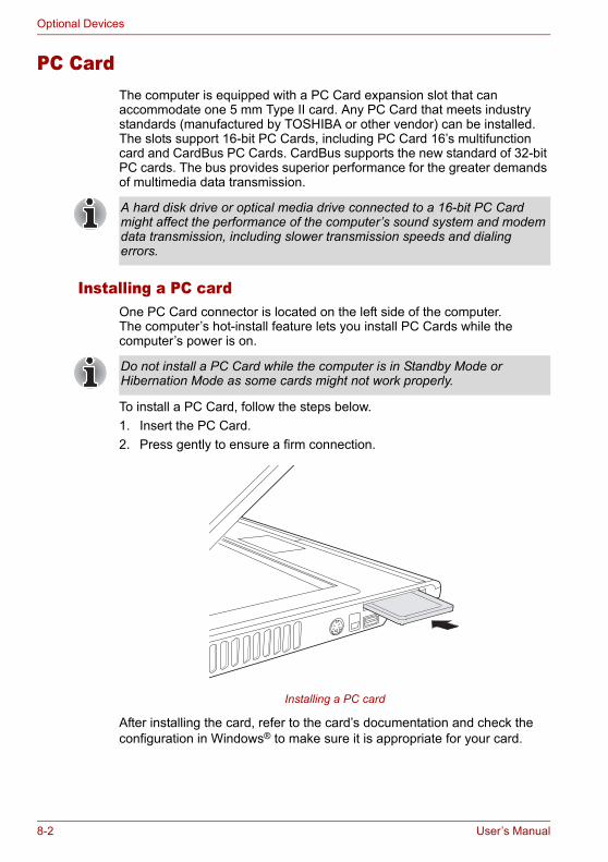
Optional Devices
PC CardThe computer is equipped with a PC Card expansion slot that can accommodate one 5 mm Type II card. Any PC Card that meets industry standards (manufactured by TOSHIBA or other vendor) can be installed. The slots support 16-bit PC Cards, including PC Card 16’s multifunction card and CardBus PC Cards. CardBus supports the new standard of 32-bit PC cards. The bus provides superior performance for the greater demands of multimedia data transmission.
Installing a PC cardOne PC Card connector is located on the left side of the computer. The computer’s hot-install feature lets you install PC Cards while the computer’s power is on.
To install a PC Card, follow the steps below.1. Insert the PC Card.2. Press gently to ensure a firm connection.
Installing a PC card
After installing the card, refer to the card’s documentation and check the configuration in Windows® to make sure it is appropriate for your card.
A hard disk drive or optical media drive connected to a 16-bit PC Card might affect the performance of the computer’s sound system and modem data transmission, including slower transmission speeds and dialing errors.
Do not install a PC Card while the computer is in Standby Mode or Hibernation Mode as some cards might not work properly.
8-2 User’s Manual
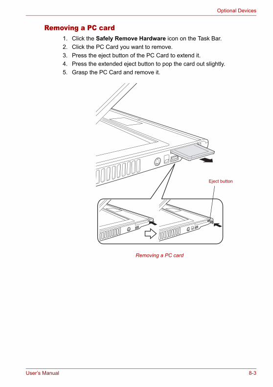
Optional Devices
Removing a PC card1. Click the Safely Remove Hardware icon on the Task Bar.2. Click the PC Card you want to remove.3. Press the eject button of the PC Card to extend it.4. Press the extended eject button to pop the card out slightly.5. Grasp the PC Card and remove it.
Removing a PC card
Eject button
User’s Manual 8-3
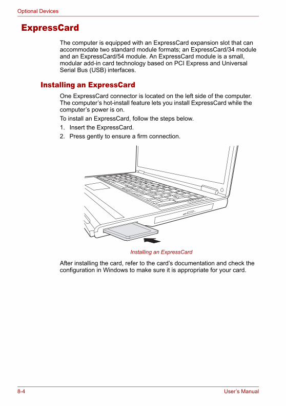
Optional Devices
ExpressCardThe computer is equipped with an ExpressCard expansion slot that can accommodate two standard module formats; an ExpressCard/34 module and an ExpressCard/54 module. An ExpressCard module is a small, modular add-in card technology based on PCI Express and Universal Serial Bus (USB) interfaces.
Installing an ExpressCardOne ExpressCard connector is located on the left side of the computer. The computer’s hot-install feature lets you install ExpressCard while the computer’s power is on.To install an ExpressCard, follow the steps below.1. Insert the ExpressCard.2. Press gently to ensure a firm connection.
Installing an ExpressCard
After installing the card, refer to the card’s documentation and check the configuration in Windows to make sure it is appropriate for your card.
8-4 User’s Manual

Optional Devices
Removing an ExpressCard1. Click the Safety Remove Hardware icon on the Task Bar.2. Click the ExpressCard you want to remove.3. Press the ExpressCard once to extend it.4. Grasp the extended ExpressCard, and remove it.
Removing an ExpressCard
SD/MMC/MS/MS Pro/xD Memory cardsThe computer is equipped with a multiple digital media card slot that can accommodate SD/MMC/MS/MS Pro/xD memory cards. These memory cards let you easily transfer data from devices, such as digital cameras and Personal Digital Assistants, which use flash-memory.
Card Type Capacities
SD 8MB, 16MB, 32MB, 64MB, 128MB, 256MB, 512MB, 1GB
MMC 8MB, 16MB, 32MB, 64MB, 128MB, 256MB
MS 8MB, 16MB, 32MB, 64MB, 128MB, 256MB
MS Pro 256MB, 512MB, 1GB
xD 8MB, 16MB, 32MB, 64MB, 128MB, 256MB, 512MB, 1GB
Keep foreign objects out of the memory card slot. A pin or similar object can damage the computer’s circuitry.
Do not format a memory card with Windows® as it might result in that card not being able to be used with some peripheral devices.
User’s Manual 8-5
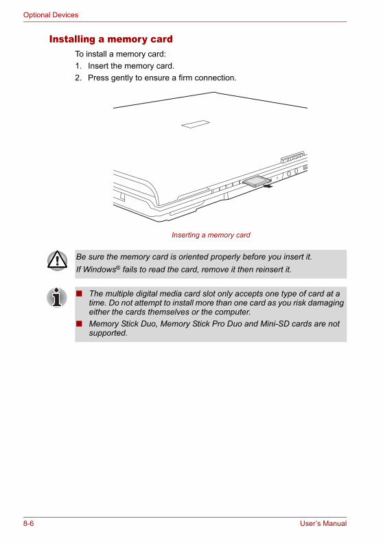
Optional Devices
Installing a memory cardTo install a memory card:1. Insert the memory card.2. Press gently to ensure a firm connection.
Inserting a memory card
Be sure the memory card is oriented properly before you insert it. If Windows® fails to read the card, remove it then reinsert it.
■ The multiple digital media card slot only accepts one type of card at a time. Do not attempt to install more than one card as you risk damaging either the cards themselves or the computer.
■ Memory Stick Duo, Memory Stick Pro Duo and Mini-SD cards are not supported.
8-6 User’s Manual
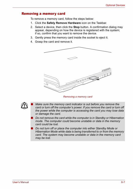
Optional Devices
Removing a memory cardTo remove a memory card, follow the steps below:1. Click the Safely Remove Hardware icon on the Taskbar.2. Select a device, then click the Stop button. A confirmation dialog may
appear, depending on how the device is registered with the system; if so, confirm that you want to remove the device.
3. Gently press the memory card inside the socket to eject it.4. Grasp the card and remove it.
Removing a memory card
■ Make sure the memory card indicator is out before you remove the card or turn off the computer’s power. If you remove the card or turn off the power while the computer is accessing the card you may lose data or damage the card.
■ Do not remove the card while the computer is in Standby or Hibernation mode. The computer could become unstable or data in the memory card could be lost.
■ Do not turn off or place the computer into either Standby Mode or Hibernation Mode while data is being transferred to or from the memory card. The system may become unstable or data in the memory card may be lost.
User’s Manual 8-7

Optional Devices
Memory card care
1. Do not write to a memory card if the battery power is low. Low power could affect writing accuracy.
2. Do not remove a memory card while read/write is in progress.3. The memory card is designed so that it can be inserted only one way.
Do not try to force the card into the slot.4. Do not leave a memory card partially inserted in the slot. Press the
memory card until you hear it click into place.5. Do not twist or bend memory cards.6. Do not expose memory cards to liquids or store in humid areas or lay
media close to containers of liquid.7. After using a memory card, return it to its case.8. Do not touch the metal part or expose it to liquids or let it get dirty.
Memory expansionYou can install additional memory in the computer’s memory module socket to increase the amount of RAM. This section describes how to install and remove a memory module.
Set the write-protect switch to the lock position, if you do not want to record data.
■ Before you install or remove a memory module, turn off the computer with the Shut Down option in the Windows Start menu. If you install or remove a memory module while the computer is in Standby or Hibernation mode, data will be lost.
■ Some memory modules can be physically installed but are not compatible with the computer. In this case the computer will issue a warning.M70: There will be a long beep, 3 short beeps, 3 more short beeps and then a long beep when you turn the power on. In this case, shut down the power and remove the incompatible memory module.CAUTION: If you want to upgrade system memory, you should only use certified modules. Ask your vendor or check the TOSHIBA web site for a list of approved memory products.
8-8 User’s Manual
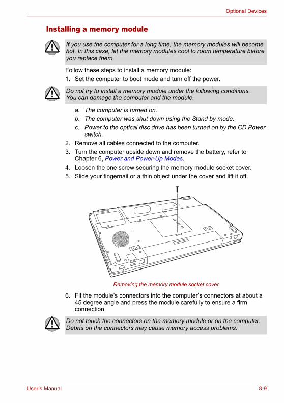
Optional Devices
Installing a memory module
Follow these steps to install a memory module:1. Set the computer to boot mode and turn off the power.
a. The computer is turned on.b. The computer was shut down using the Stand by mode.c. Power to the optical disc drive has been turned on by the CD Power
switch.2. Remove all cables connected to the computer.3. Turn the computer upside down and remove the battery, refer to
Chapter 6, Power and Power-Up Modes.4. Loosen the one screw securing the memory module socket cover.5. Slide your fingernail or a thin object under the cover and lift it off.
Removing the memory module socket cover
6. Fit the module’s connectors into the computer’s connectors at about a 45 degree angle and press the module carefully to ensure a firm connection.
If you use the computer for a long time, the memory modules will become hot. In this case, let the memory modules cool to room temperature before you replace them.
Do not try to install a memory module under the following conditions. You can damage the computer and the module.
Do not touch the connectors on the memory module or on the computer. Debris on the connectors may cause memory access problems.
User’s Manual 8-9
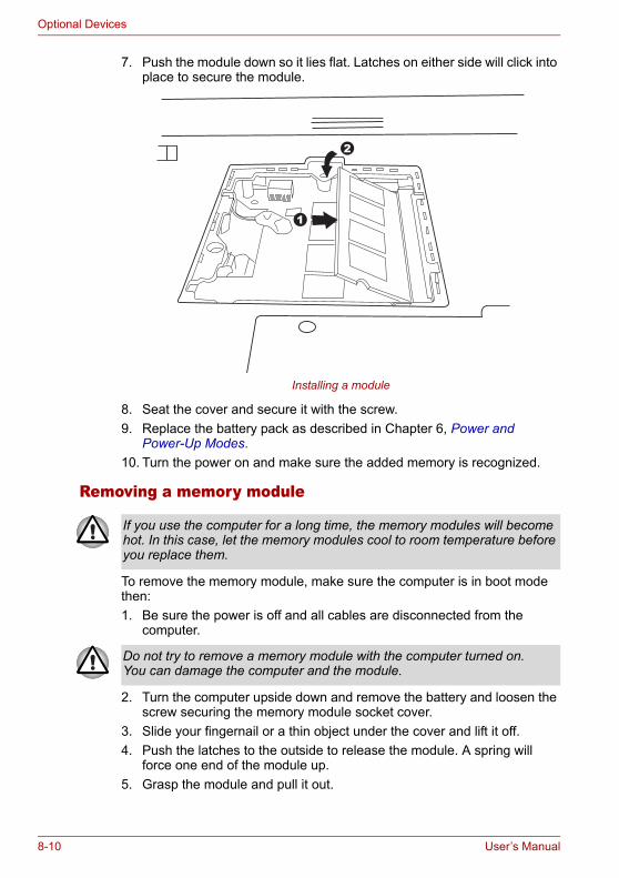
Optional Devices
7. Push the module down so it lies flat. Latches on either side will click into place to secure the module.
Installing a module
8. Seat the cover and secure it with the screw.9. Replace the battery pack as described in Chapter 6, Power and
Power-Up Modes.10. Turn the power on and make sure the added memory is recognized.
Removing a memory module
To remove the memory module, make sure the computer is in boot mode then:1. Be sure the power is off and all cables are disconnected from the
computer.
2. Turn the computer upside down and remove the battery and loosen the screw securing the memory module socket cover.
3. Slide your fingernail or a thin object under the cover and lift it off.4. Push the latches to the outside to release the module. A spring will
force one end of the module up.5. Grasp the module and pull it out.
1
2
If you use the computer for a long time, the memory modules will become hot. In this case, let the memory modules cool to room temperature before you replace them.
Do not try to remove a memory module with the computer turned on. You can damage the computer and the module.
8-10 User’s Manual
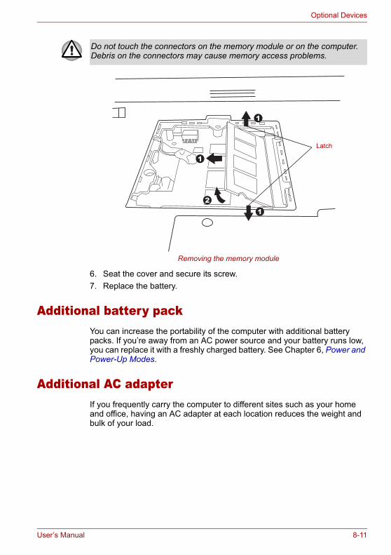
Optional Devices
Removing the memory module
6. Seat the cover and secure its screw.7. Replace the battery.
Additional battery packYou can increase the portability of the computer with additional battery packs. If you’re away from an AC power source and your battery runs low, you can replace it with a freshly charged battery. See Chapter 6, Power and Power-Up Modes.
Additional AC adapterIf you frequently carry the computer to different sites such as your home and office, having an AC adapter at each location reduces the weight and bulk of your load.
Do not touch the connectors on the memory module or on the computer. Debris on the connectors may cause memory access problems.
1
1
12
Latch
User’s Manual 8-11
Optional Devices
External monitorAn external analog monitor can be connected to the external monitor port on the computer. To connect a monitor, follow the steps below.1. Turn the computer off.2. Connect the monitor to the external monitor port.3. Turn the monitor’s power on.4. Turn the computer on.When you turn on the power, the computer automatically recognizes the monitor.To change the display settings, press Fn + F5. If you disconnect the monitor before you turn the computer off, be sure to press Fn + F5 to switch to the internal display. Refer to Chapter 5, The Keyboard, for details on using hot keys to change the display setting.
TelevisionA television can be connected to the video out port on the computer. To connect a television, follow the steps below.1. Turn the computer off.2. Use a video cable (not supplied) to connect the television to the video
out port.3. Turn the television on.4. Turn the computer on.You can use the hotkeys Fn + F5 or use the TV-Out button to change the display device. Refer to Chapter 5, The Keyboard.If a television is connected to the computer, set the TV type in Display Properties. Follow the steps below.
8-12 User’s Manual
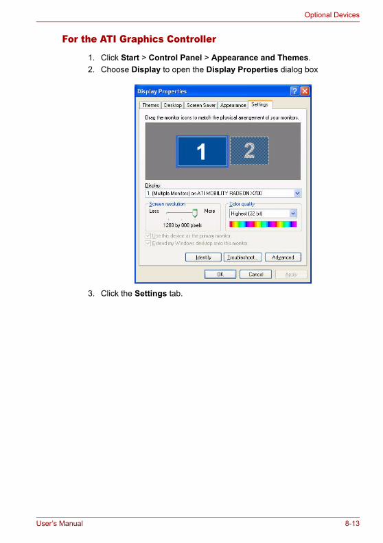
Optional Devices
For the ATI Graphics Controller
1. Click Start > Control Panel > Appearance and Themes.2. Choose Display to open the Display Properties dialog box
3. Click the Settings tab.
User’s Manual 8-13
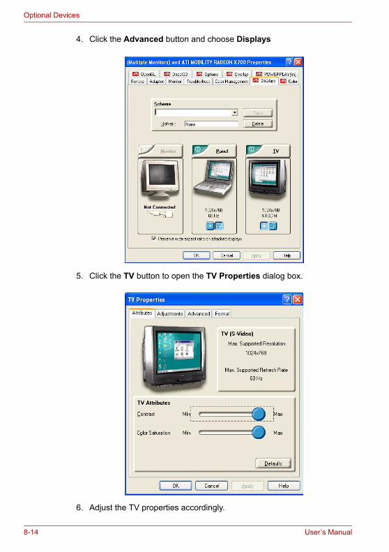
Optional Devices
4. Click the Advanced button and choose Displays
5. Click the TV button to open the TV Properties dialog box.
6. Adjust the TV properties accordingly.
8-14 User’s Manual
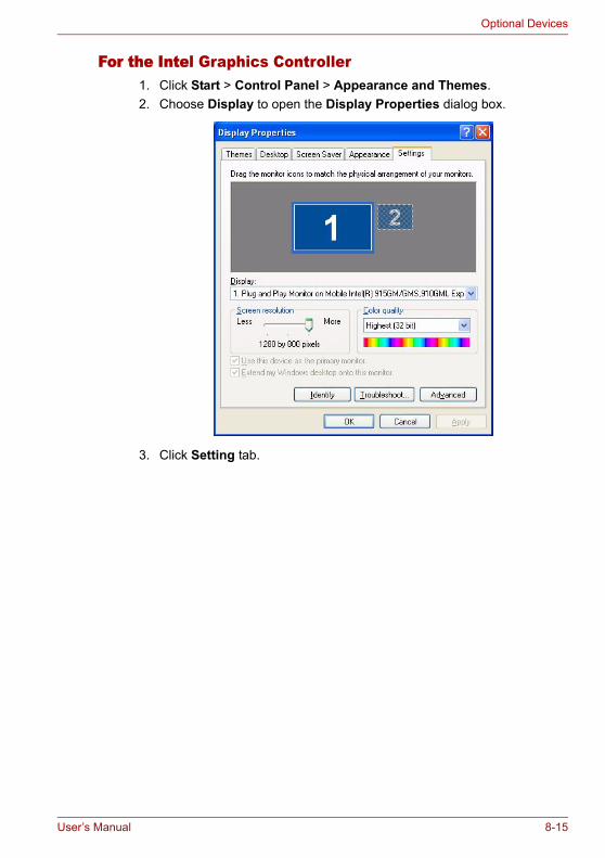
Optional Devices
For the Intel Graphics Controller1. Click Start > Control Panel > Appearance and Themes.2. Choose Display to open the Display Properties dialog box.
3. Click Setting tab.
User’s Manual 8-15

Optional Devices
4. Click the Advanced button and choose Intel® Graphics Media Accelerator Driver.
5. Click the Graphic Properties button and choose TV.
6. Adjusting the TV settings.
8-16 User’s Manual
Optional Devices
i.LINK (IEEE1394)i.LINK (IEEE1394) is used for high-speed data transfer for a range of compatible devices such as:■ Digital video cameras■ Hard disk drives■ MO drives■ Optical disc drives
Precautions■ Make a back-up of your data before transferring it to the computer.
There is a possibility that the original data will be damaged. There is a particular risk that some frames will be deleted in the case of digital video transfer.
■ Do not transfer data in areas where static electricity is easily generated or in areas subjected to electronic noise. Data can be destroyed.
■ If you are transferring data through an IEEE1394 hub, do not connect or disconnect other devices from the hub during data transfer. There is a likelihood that data will be damaged. Connect all devices to the hub before you turn on the computer’s power.
Connecting1. Make sure the connectors are properly aligned and plug the i.LINK
(IEEE1394) cable into the computer.2. Plug the other end of the cable into the device.Note the following when you use i.LINK:■ You may need to install drivers for your i.LINK devices.■ Not all i.LINK devices have been tested. Therefore, compatibility with all
i.LINK devices cannot be guaranteed.■ Use S100, S200 or S400 cables no longer than three meters.■ Some devices might not support standby or automatic off functions.■ Do not connect or disconnect an i.LINK device while it is using an
application or when the computer is automatically shutting it down to save power. Data might be destroyed.
Disconnecting1. Click the Safely Remove Hardware icon on the Task Bar.2. Point to i.LINK (IEEE1394) device and click.3. Disconnect the cable from the computer then from the i.LINK device.
i.LINK uses a four-pin connector, which does not carry electric current. External devices will need their own power supply.
Refer also to the documentation that came with your i.LINK device.
User’s Manual 8-17
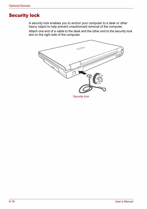
Optional Devices
Security lockA security lock enables you to anchor your computer to a desk or other heavy object to help prevent unauthorized removal of the computer.Attach one end of a cable to the desk and the other end to the security lock slot on the right side of the computer.
Security lock
8-18 User’s Manual
Chapter 9
Troubleshooting
TOSHIBA designed the computer for durability. However, should problems occur, following the procedures in this chapter can help to determine the cause.All readers should become familiar with this chapter. Knowing what might go wrong can help prevent problems from occurring.
Problem solving processResolving problems will be much easier if you observe the following guidelines:■ Stop immediately when you recognize a problem exists. Further action
may result in data loss or damage. You may destroy valuable problem-related information that can help solve the problem.
■ Observe what is happening. Write down what the system is doing and what actions you performed immediately before the problem occurred. If you have a printer attached, print a copy of the screen using PrtSc.
■ Isolate the problem. Using the tools available to you, such as the troubleshooting tips in this chapter, try to discover the specific actions that caused the problem.
The questions and procedures offered in this chapter are meant as a guide, they are not definitive problem solving techniques. Many problems can be solved simply, but a few may require help from your dealer. If you find you need to consult your dealer or others, be prepared to describe the problem in as much detail as possible.
User’s Manual 9-1

Troubleshooting
Preliminary checklistConsider the simplest solution first. The items in this checklist are easy to fix and yet can cause what appears to be a serious problem.■ Make sure you turn on all peripheral devices before you turn on the
computer. This includes your printer and any other external device you are using.
■ Before you attach an external device, turn the computer off. When you turn the computer back on it recognizes the new device.
■ Make sure all options are set properly in the setup program.■ Check all cables. Are they correctly and firmly attached? Loose cables
can cause signal errors.■ Inspect all connecting cables for loose wires and all connectors for
loose pins.■ Check that the optical disc drive is correctly inserted.Make notes of your observations and keep them in a permanent error log. This will help you describe your problems to your dealer. If a problem recurs, the log will help you identify the problem faster.
Analyzing the problemSometimes the system gives clues that can help you identify why it is malfunctioning. Keep the following questions in mind:■ Which part of the system is not operating properly: keyboard, disk
drives, hard disk drive, printer, display. Each device produces different symptoms.
■ Is the operating system configuration set properly? Check the configuration options.
■ What appears on the display screen? Does it display any messages or random characters? Print a copy of the screen if you have a printer attached. Look up the messages in the software and operating system documentation. Check that all connecting cables are correctly and firmly attached. Loose cables can cause erroneous or intermittent signals.
■ Do any indicators light? Which ones? What color are they? Do they stay on or blink? Write down what you see.
■ Do you hear any beeps? How many? Are they long or short? Are they high pitched or low? Is the computer making any unusual noises? Write down what you hear.
Record your observations so you can describe them to your dealer.
9-2 User’s Manual

Troubleshooting
Hardware and system checklistThis section discusses problems caused by your computer’s hardware or attached peripherals. Basic problems may occur in the following areas:
System start-upWhen the computer does not start properly, check the following items:■ Self Test■ Power Sources■ Power-on Password
Software The problems may be caused by your software. If you cannot load a software package, the media may be damaged or the program might be corrupted. Try loading another copy of the software.If an error message appears while you are using a software package, check the software documentation. These documents usually include a problem solving section or a summary of error messages.Next, check any error messages in the operating system documentation.
Hardware If you cannot find a software problem, check your hardware. First run through the items in the preliminary checklist above. If you still cannot correct the problem, try to identify the source. The next section provides checklists for individual components and peripherals.
■ System start-up ■ Sound system■ Self test ■ Pointing device■ Power ■ USB■ Overheating power down ■ TV output signal■ AC Power ■ LAN ■ Battery ■ Standby/Hibernation■ Password ■ Memory expansion■ Keyboard ■ Modem■ LCD panel ■ i.LINK (IEEE1394)■ Hard disk drive ■ DVD Super Multi drive supporting
±R Double Layer■ Memory cards■ Wireless LAN ■ CD-RW/DVD-ROM drive■ PC Card ■ Disk drive■ Express Card ■ Real Time Clock■ Monitor
User’s Manual 9-3
Troubleshooting
Self testWhen the computer starts up, the self test will be run automatically, and the following will be displayed:
This message remains on the screen for a few seconds.If the self test is successful, the computer tries to load the operating system based around how the Boot Priority option is set within the computer’s BIOS setup.If any of the following conditions are present, the self test failed:■ The computer stops and does not proceed to display information or
messages except the TOSHIBA logo.■ Random characters appear on the screen, and the system does not
function normally.■ The screen displays an error message.Turn off the computer and check all cable connections as well as PC Card and memory module connections. If the test fails again, contact your dealer.
PowerWhen the computer is not plugged into an AC outlet, the battery pack is the primary power source. However, your computer has a number of other power resources, including an intelligent power supply and Real Time Clock battery. These resources are interrelated and any one could affect apparent power problems. This section provides check lists for AC power and the battery. If you cannot resolve a problem after following them, the cause could lie with another power resource. In such cases you should contact your dealer.
Overheating power downIf the computer’s internal temperature becomes too high, the computer will automatically shut down
(This screen image is provided as an example. You may see a different imagedepending on the model you purchased)
9-4 User’s Manual
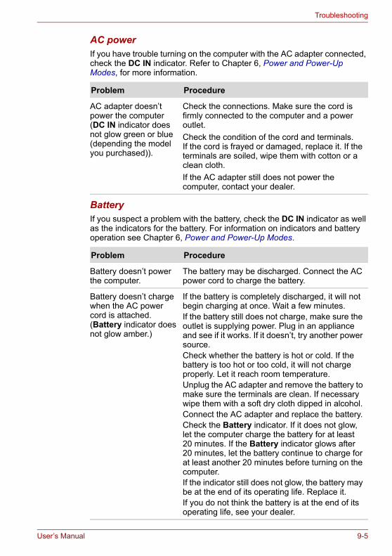
Troubleshooting
AC powerIf you have trouble turning on the computer with the AC adapter connected, check the DC IN indicator. Refer to Chapter 6, Power and Power-Up Modes, for more information.
BatteryIf you suspect a problem with the battery, check the DC IN indicator as well as the indicators for the battery. For information on indicators and battery operation see Chapter 6, Power and Power-Up Modes.
Problem Procedure
AC adapter doesn’t power the computer (DC IN indicator does not glow green or blue (depending the model you purchased)).
Check the connections. Make sure the cord is firmly connected to the computer and a power outlet.Check the condition of the cord and terminals. If the cord is frayed or damaged, replace it. If the terminals are soiled, wipe them with cotton or a clean cloth.If the AC adapter still does not power the computer, contact your dealer.
Problem Procedure
Battery doesn’t power the computer.
The battery may be discharged. Connect the AC power cord to charge the battery.
Battery doesn’t charge when the AC power cord is attached. (Battery indicator does not glow amber.)
If the battery is completely discharged, it will not begin charging at once. Wait a few minutes.If the battery still does not charge, make sure the outlet is supplying power. Plug in an appliance and see if it works. If it doesn’t, try another power source.Check whether the battery is hot or cold. If the battery is too hot or too cold, it will not charge properly. Let it reach room temperature. Unplug the AC adapter and remove the battery to make sure the terminals are clean. If necessary wipe them with a soft dry cloth dipped in alcohol.Connect the AC adapter and replace the battery.Check the Battery indicator. If it does not glow, let the computer charge the battery for at least 20 minutes. If the Battery indicator glows after 20 minutes, let the battery continue to charge for at least another 20 minutes before turning on the computer.If the indicator still does not glow, the battery may be at the end of its operating life. Replace it.If you do not think the battery is at the end of its operating life, see your dealer.
User’s Manual 9-5
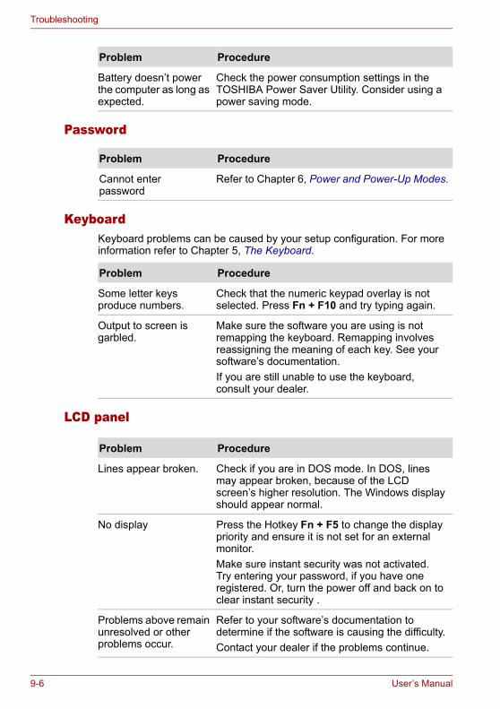
Troubleshooting
Password
KeyboardKeyboard problems can be caused by your setup configuration. For more information refer to Chapter 5, The Keyboard.
LCD panel
Battery doesn’t power the computer as long as expected.
Check the power consumption settings in the TOSHIBA Power Saver Utility. Consider using a power saving mode.
Problem Procedure
Problem Procedure
Cannot enter password
Refer to Chapter 6, Power and Power-Up Modes.
Problem Procedure
Some letter keys produce numbers.
Check that the numeric keypad overlay is not selected. Press Fn + F10 and try typing again.
Output to screen is garbled.
Make sure the software you are using is not remapping the keyboard. Remapping involves reassigning the meaning of each key. See your software’s documentation.If you are still unable to use the keyboard, consult your dealer.
Problem Procedure
Lines appear broken. Check if you are in DOS mode. In DOS, lines may appear broken, because of the LCD screen’s higher resolution. The Windows display should appear normal.
No display Press the Hotkey Fn + F5 to change the display priority and ensure it is not set for an external monitor.Make sure instant security was not activated. Try entering your password, if you have one registered. Or, turn the power off and back on to clear instant security .
Problems above remain unresolved or other problems occur.
Refer to your software’s documentation to determine if the software is causing the difficulty.Contact your dealer if the problems continue.
9-6 User’s Manual

Troubleshooting
Hard disk drive
Memory CardRefer also to Chapter 8, Optional Devices.
Wireless LANIf the following procedures do not restore LAN access, consult your LAN administrator. For more information on wireless communication, refer to Chapter 4, Operating Basics.
Problem Procedure
Computer does not boot from hard drive.
Insert a system disk and reboot.There may be a problem with your operating system files. Refer to your operating system documentation.
Slow performance Your files may be fragmented. Run SCANDISK and defragmenter to check the condition of your files and disk. Refer to your operating system documentation or online HELP for information on running SCANDISK and the defragmenter.Contact your dealer if the problems continue.
Problem Procedure
Memory card error occurs
Reseat the memory card to make sure it is firmly connected.
Check the card’s documentation.If problems persist, contact your dealer.
Problem Procedure
Cannot access Wireless LAN
Make sure the computer’s wireless communication switch is set to on.Use the Config Free program that comes pre-installed in your computer to see LAN status.If problems persist, consult your LAN administrator.
User’s Manual 9-7

Troubleshooting
PC CardRefer also to Chapter 8, Optional Devices.
MonitorRefer also to Chapter 8, Optional Devices, and to your monitor’s documentation.
Problem Procedure
PC Card error occurs Reseat the PC Card to make sure it is firmly connected.Make sure the connection between the external device and the card is firm.Check the card’s documentation.If problems persist, contact your dealer.
Problem Procedure
Monitor does not turn on
Make sure that the external monitor’s power switch is on. Confirm that the external monitor’s power cable is plugged into a working power outlet.
No display Try adjusting the contrast and brightness controls on the external monitor.Press hotkeys Fn + F5 to change the display priority and make sure it is not set for the internal display.
Display error occurs Check that the cable connecting the external monitor to the computer is attached firmly.If problems persist, contact your dealer.
Monitor goes into panning mode
Check your monitor specification. It might not support the selected resolution and refresh rate. The resolution on the monitor might go into panning mode when wide screen resolution is selected. Refer to Appendix B, Display Modes.
9-8 User’s Manual
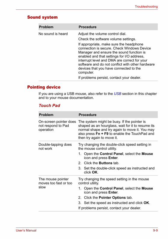
Troubleshooting
Sound system
Pointing deviceIf you are using a USB mouse, also refer to the USB section in this chapter and to your mouse documentation.
Touch Pad
Problem Procedure
No sound is heard Adjust the volume control dial.Check the software volume settings.If appropriate, make sure the headphone connection is secure. Check Windows Device Manager and ensure the sound function is enabled and that settings for I/O address, interrupt level and DMA are correct for your software and do not conflict with other hardware devices that you have connected to the computer.If problems persist, contact your dealer.
Problem Procedure
On-screen pointer does not respond to Pad operation
The system might be busy. If the pointer is shaped as an hourglass, wait for it to resume its normal shape and try again to move it. You may also press Fn + F9 to enable the TouchPad and then try again to move it.
Double-tapping does not work
Try changing the double-click speed setting in the mouse control utility.1. Open the Control Panel, select the Mouse
icon and press Enter.2. Click the Buttons tab.3. Set the double-click speed as instructed and
click OK.
The mouse pointer moves too fast or too slow
Try changing the speed setting in the mouse control utility.1. Open the Control Panel, select the Mouse
icon and press Enter.2. Click the Pointer Options tab.3. Set the speed as instructed and click OK.If problems persist, contact your dealer.
User’s Manual 9-9
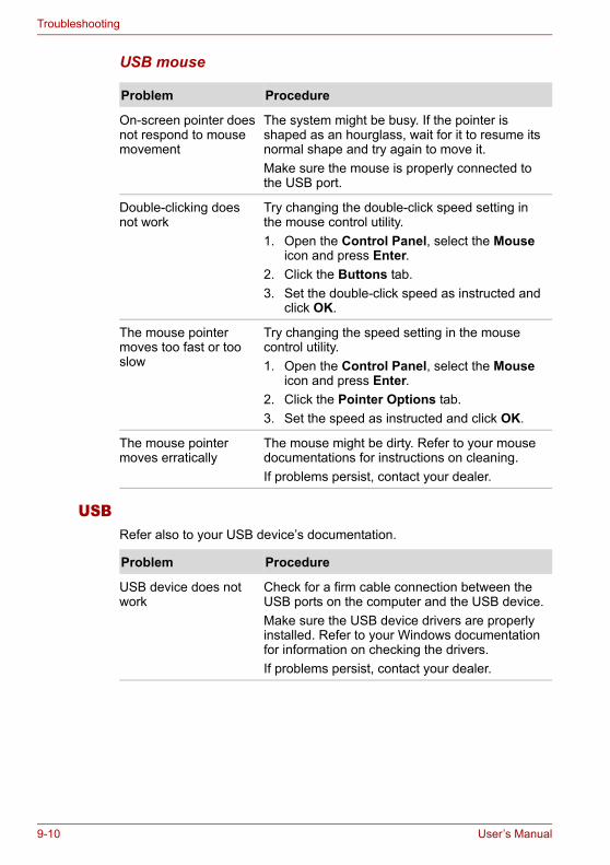
Troubleshooting
USB mouse
USBRefer also to your USB device’s documentation.
Problem Procedure
On-screen pointer does not respond to mouse movement
The system might be busy. If the pointer is shaped as an hourglass, wait for it to resume its normal shape and try again to move it.Make sure the mouse is properly connected to the USB port.
Double-clicking does not work
Try changing the double-click speed setting in the mouse control utility.1. Open the Control Panel, select the Mouse
icon and press Enter.2. Click the Buttons tab.3. Set the double-click speed as instructed and
click OK.
The mouse pointer moves too fast or too slow
Try changing the speed setting in the mouse control utility.1. Open the Control Panel, select the Mouse
icon and press Enter.2. Click the Pointer Options tab.3. Set the speed as instructed and click OK.
The mouse pointer moves erratically
The mouse might be dirty. Refer to your mouse documentations for instructions on cleaning.If problems persist, contact your dealer.
Problem Procedure
USB device does not work
Check for a firm cable connection between the USB ports on the computer and the USB device.Make sure the USB device drivers are properly installed. Refer to your Windows documentation for information on checking the drivers.If problems persist, contact your dealer.
9-10 User’s Manual
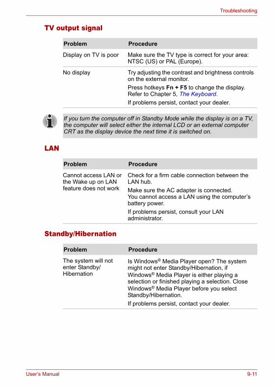
Troubleshooting
TV output signal
LAN
Standby/Hibernation
Problem Procedure
Display on TV is poor Make sure the TV type is correct for your area: NTSC (US) or PAL (Europe).
No display Try adjusting the contrast and brightness controls on the external monitor.Press hotkeys Fn + F5 to change the display. Refer to Chapter 5, The Keyboard.If problems persist, contact your dealer.
If you turn the computer off in Standby Mode while the display is on a TV, the computer will select either the internal LCD or an external computer CRT as the display device the next time it is switched on.
Problem Procedure
Cannot access LAN or the Wake up on LAN feature does not work
Check for a firm cable connection between the LAN hub.Make sure the AC adapter is connected. You cannot access a LAN using the computer’s battery power.If problems persist, consult your LAN administrator.
Problem Procedure
The system will not enter Standby/Hibernation
Is Windows® Media Player open? The system might not enter Standby/Hibernation, if Windows® Media Player is either playing a selection or finished playing a selection. Close Windows® Media Player before you select Standby/Hibernation.If problems persist, contact your dealer.
User’s Manual 9-11
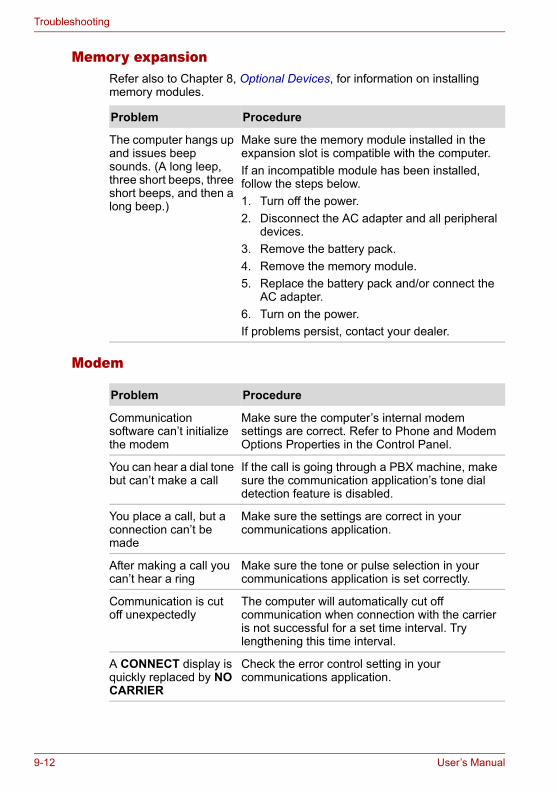
Troubleshooting
Memory expansionRefer also to Chapter 8, Optional Devices, for information on installing memory modules.
Modem
Problem Procedure
The computer hangs up and issues beep sounds. (A long leep, three short beeps, three short beeps, and then a long beep.)
Make sure the memory module installed in the expansion slot is compatible with the computer.If an incompatible module has been installed, follow the steps below.1. Turn off the power.2. Disconnect the AC adapter and all peripheral
devices.3. Remove the battery pack.4. Remove the memory module.5. Replace the battery pack and/or connect the
AC adapter.6. Turn on the power.If problems persist, contact your dealer.
Problem Procedure
Communication software can’t initialize the modem
Make sure the computer’s internal modem settings are correct. Refer to Phone and Modem Options Properties in the Control Panel.
You can hear a dial tone but can’t make a call
If the call is going through a PBX machine, make sure the communication application’s tone dial detection feature is disabled.
You place a call, but a connection can’t be made
Make sure the settings are correct in your communications application.
After making a call you can’t hear a ring
Make sure the tone or pulse selection in your communications application is set correctly.
Communication is cut off unexpectedly
The computer will automatically cut off communication when connection with the carrier is not successful for a set time interval. Try lengthening this time interval.
A CONNECT display is quickly replaced by NO CARRIER
Check the error control setting in your communications application.
9-12 User’s Manual

Troubleshooting
i.LINK (IEEE1394)
DVD Super Multi drive supporting ±R Double LayerFor more information, refer to Chapter 4, Operating Basics.
Character display becomes garbled during a communication
In data transmission, make sure the parity bit and stop bit settings correspond with those of the remote computer.Check the flow control and communication protocol.
You cannot receive an incoming call
Check the “rings before auto answer” setting in your communications application.If problems persist, contact your dealer.
Problem Procedure
Problem Procedure
i.LINK device does not function
Make sure the cable is securely connected to the computer and to the device.Make sure the device’s power is turned on.Reinstall the drivers. Open the Windows Control Panel and double-click the Add New Hardware icon. Follow the on-screen directions.Restart Windows.If problems persist, contact your dealer.
Problem Procedure
You cannot access a disc in the drive
Make sure the drive’s drawer is securely closed. Press gently until it clicks into place.Open the drawer and make sure the disc is properly seated. It should lie flat with the label facing up.A foreign object in the drawer could block laser light from reading the disc. Make sure there is no obstruction. Remove any foreign object.Check whether the disc is dirty. If it is, wipe it with a clean cloth dipped in water or a neutral cleaner. See the Media care section in Chapter 4 for details on cleaning.
User’s Manual 9-13
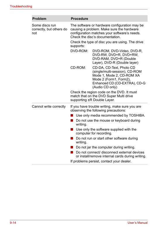
Troubleshooting
Some discs run correctly, but others do not
The software or hardware configuration may be causing a problem. Make sure the hardware configuration matches your software’s needs. Check the disc’s documentation.Check the type of disc you are using. The drive supports:DVD-ROM: DVD-ROM, DVD-Video, DVD-R,
DVD-RW, DVD+R, DVD+RW, DVD-RAM, DVD+R (Double Layer), DVD-R (Double layer)
CD-ROM: CD-DA, CD-Text, Photo CD (single/multi-session), CD-ROM Mode 1, Mode 2, CD-ROM XA Mode 2 (Form1, Form2), Enhanced CD (CD-EXTRA), CD-G (Audio CD only)
Check the region code on the DVD. It must match that on the DVD Super Multi drive supporting ±R Double Layer.
Cannot write correctly If you have trouble writing, make sure you are observing the following precautions:■ Use only media recommended by TOSHIBA.■ Do not use the mouse or keyboard during
writing.■ Use only the software supplied with the
computer for recording.■ Do not run or start other software during
writing.■ Do not jar the computer during writing.■ Do not connect/ disconnect external devices
or install/remove internal cards during writing.If problems persist, contact your dealer.
Problem Procedure
9-14 User’s Manual

Troubleshooting
CD-RW/DVD-ROM driveFor more information, refer to Chapter 4, Operating Basics.
Problem Procedure
You cannot access a disc in the drive
Make sure the drive’s drawer is securely closed. Press gently until it clicks into place.Open the drawer and make sure the disc is properly seated. It should lie flat with the label facing up.A foreign object in the drawer could block laser light from reading the disc. Make sure there is no obstruction. Remove any foreign object.Check whether the disc is dirty. If it is, wipe it with a clean cloth dipped in water or a neutral cleaner. Refer to Media Care section in Chapter 4 for details on cleaning.
Some discs run correctly, but others do not
The software or hardware configuration may be causing a problem. Make sure the hardware configuration matches your software’s needs. Check the disc’s documentation.Check the type of disc you are using. The drive supports:DVD-ROM: DVD-ROM, DVD-VideoCD-ROM: CD-DA, CD-Text, Photo CD™
(single/multi-session), CD-ROM Mode 1, Mode 2, CD-ROM XA Mode 2 (Form1, Form2), Enhanced CD (CD-EXTRA), CD-G (Audio CD only)
Recordable: CD-R, CD-RWCheck the region code on the DVD. It must match that on the CD-RW/DVD-ROM drive. Region codes are listed in the optical disc section in Chapter 2, The Grand Tour.
User’s Manual 9-15
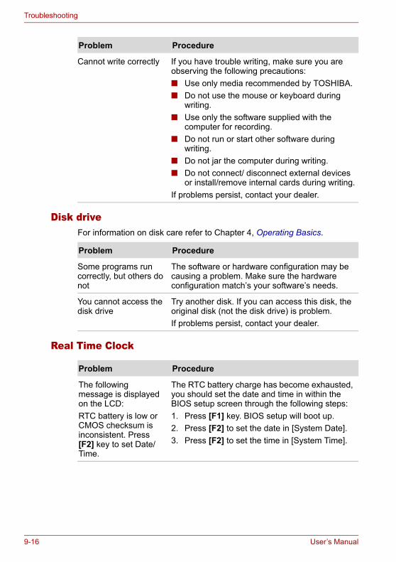
Troubleshooting
Disk driveFor information on disk care refer to Chapter 4, Operating Basics.
Real Time Clock
Cannot write correctly If you have trouble writing, make sure you are observing the following precautions:■ Use only media recommended by TOSHIBA.■ Do not use the mouse or keyboard during
writing.■ Use only the software supplied with the
computer for recording.■ Do not run or start other software during
writing.■ Do not jar the computer during writing.■ Do not connect/ disconnect external devices
or install/remove internal cards during writing.If problems persist, contact your dealer.
Problem Procedure
Problem Procedure
Some programs run correctly, but others do not
The software or hardware configuration may be causing a problem. Make sure the hardware configuration match’s your software’s needs.
You cannot access the disk drive
Try another disk. If you can access this disk, the original disk (not the disk drive) is problem.If problems persist, contact your dealer.
Problem Procedure
The following message is displayed on the LCD:RTC battery is low or CMOS checksum is inconsistent. Press [F2] key to set Date/Time.
The RTC battery charge has become exhausted, you should set the date and time in within the BIOS setup screen through the following steps:1. Press [F1] key. BIOS setup will boot up.2. Press [F2] to set the date in [System Date].3. Press [F2] to set the time in [System Time].
9-16 User’s Manual
Troubleshooting
TOSHIBA supportIf you require any additional help using your computer or if you are having problems operating the computer, you may need to contact TOSHIBA for additional technical assistance.
Before you callSome problems you experience may be related to software or the operating system, it is important to investigate other sources of assistance first. Before contacting TOSHIBA, try the following:■ Review troubleshooting sections in the documentation for software and
peripheral devices.■ If a problem occurs when you are running software applications, consult
the software documentation for troubleshooting suggestions. Call the software company’s technical support for assistance.
■ Consult the dealer you purchased your computer and/or software from. They are your best sources for current information and support.
Where to writeIf you are still unable to solve the problem and suspect that it is hardware related, write to TOSHIBA at the location listed in the accompanying warranty booklet or visit www.toshiba-europe.com on the Internet.
User’s Manual 9-17

Troubleshooting
9-18 User’s Manual
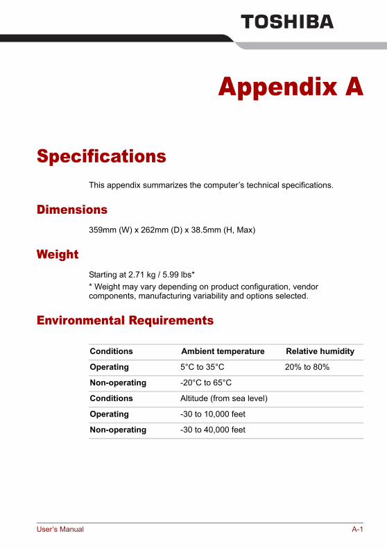
Appendix A
SpecificationsThis appendix summarizes the computer’s technical specifications.
Dimensions359mm (W) x 262mm (D) x 38.5mm (H, Max)
WeightStarting at 2.71 kg / 5.99 lbs** Weight may vary depending on product configuration, vendor components, manufacturing variability and options selected.
Environmental Requirements
Conditions Ambient temperature Relative humidity
Operating 5°C to 35°C 20% to 80%
Non-operating -20°C to 65°C
Conditions Altitude (from sea level)
Operating -30 to 10,000 feet
Non-operating -30 to 40,000 feet
User’s Manual A-1
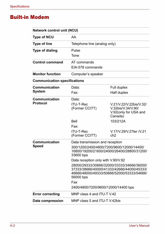
Specifications
Built-in Modem
Network control unit (NCU)
Type of NCU AA
Type of line Telephone line (analog only)
Type of dialing PulseTone
Control command AT commandsEIA-578 commands
Monitor function Computer’s speaker
Communication specifications
Communication System
Data: Fax:
Full duplexHalf duplex
Communication Protocol
Data:ITU-T-Rec (Former CCITT)
BellFax: ITU-T-Rec(Former CCITT)
V.21/V.22/V.22bis/V.32/ V.32bis/V.34/V.90/ V.92(only for USA and Canada)103/212A
V.17/V.29/V.27ter /V.21 ch2
Communication Speed
Data transmission and reception300/1200/2400/4800/7200/9600/12000/14400/16800/19200/21600/24000/26400/28800/31200/ 33600 bpsData reception only with V.90/V.9228000/29333/30666/32000/33333/34666/36000/37333/38666/40000/41333/42666/44000/45333/46666/48000/49333/50666/52000/53333/54666/ 56000 bpsFax2400/4800/7200/9600/12000/14400 bps
Error correcting MNP class 4 and ITU-T V.42
Data compression MNP class 5 and ITU-T V.42bis
A-2 User’s Manual

Appendix B
Display Modes
This appendix contains a table listing all the display modes when the display is set to an external monitor.
CRT Display Resolution
Color Depth (bit) Refresh Rate (Hz)
800 x 600 16 bit 60, 75, 85, 100
32 bit 60, 75, 85, 100
1024 x 768 16 bit 60, 75, 85, 100
32 bit 60, 75, 85, 100
1280 x 800 16 bit 60
32 bit 60
1280 x 1024 16 bit 60, 75, 85, 100
32 bit 60, 75, 85, 100
1600 x 1200 16 bit 60, 75, 85, 100
32 bit 60, 75, 85, 100
1920 x 1440 16 bit 60, 75
32 bit 60, 75
2048 x 1536 16 bit 60
32 bit 60
User’s Manual B-1

Display Modes
Displaying movies on a TV or CRTThis section describes how to set up your system to display movies simultaneously on your computer’s LCD and on an external TV or CRT monitor.Follow the steps below.
For the ATI Graphics Controller1. Open the Control Panel and click Appearance and Themes.2. Click Display.3. Select the Settings tab and click Advanced.4. Click the Displays tab.5. Select the external display device you wish to use. It must be connected
to the computer in order to be selected from the menu here.
B-2 User’s Manual
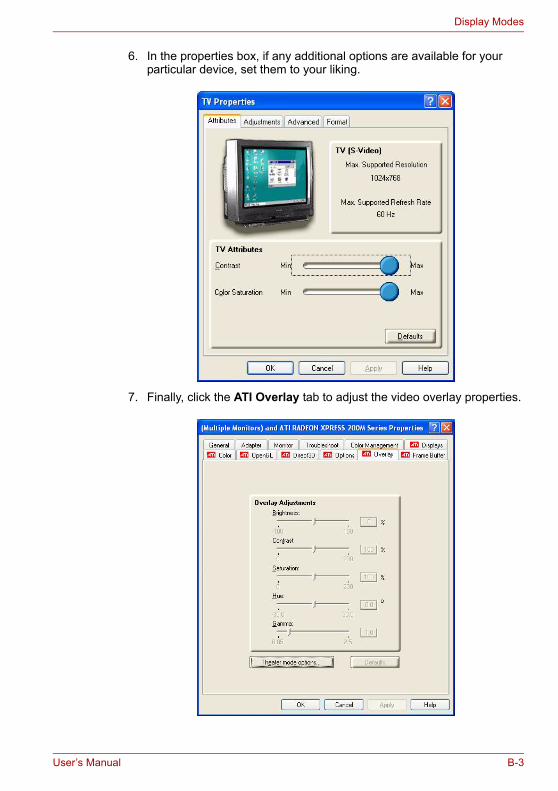
Display Modes
6. In the properties box, if any additional options are available for your particular device, set them to your liking.
7. Finally, click the ATI Overlay tab to adjust the video overlay properties.
User’s Manual B-3
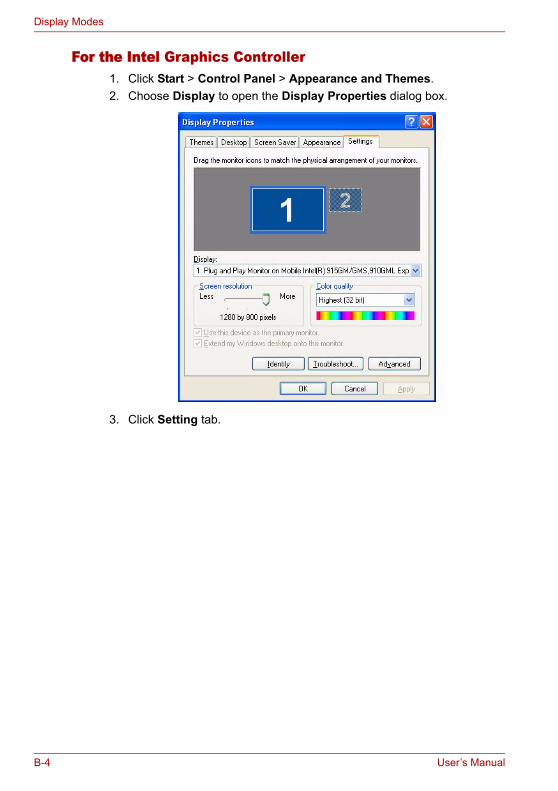
Display Modes
For the Intel Graphics Controller1. Click Start > Control Panel > Appearance and Themes.2. Choose Display to open the Display Properties dialog box.
3. Click Setting tab.
B-4 User’s Manual

Display Modes
4. Click the Advanced button and choose Intel® Graphics Media Accelerator Driver.
5. Click the Graphic Properties button and choose TV.
6. Adjusting the TV settings.
User’s Manual B-5
Display Modes
B-6 User’s Manual
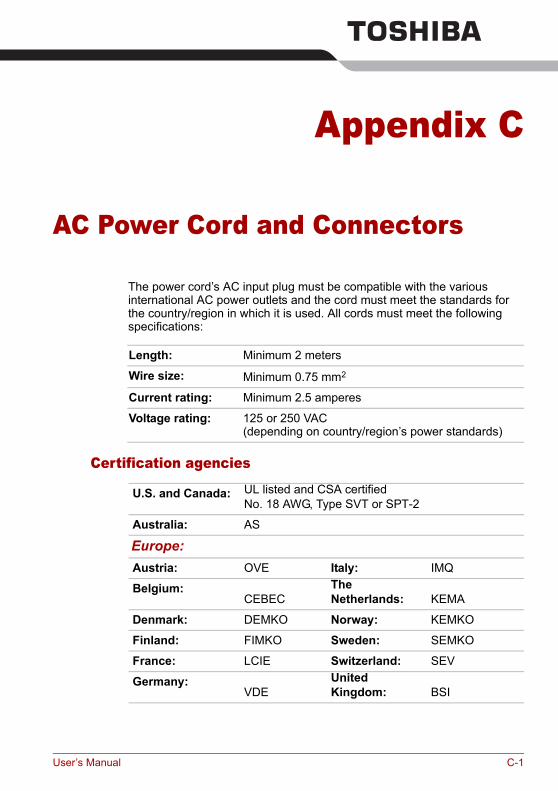
Appendix C
AC Power Cord and Connectors
The power cord’s AC input plug must be compatible with the various international AC power outlets and the cord must meet the standards for the country/region in which it is used. All cords must meet the following specifications:
Certification agencies
Length: Minimum 2 meters
Wire size: Minimum 0.75 mm2
Current rating: Minimum 2.5 amperes
Voltage rating: 125 or 250 VAC(depending on country/region’s power standards)
U.S. and Canada: UL listed and CSA certifiedNo. 18 AWG, Type SVT or SPT-2
Australia: AS
Europe:Austria: OVE Italy: IMQ
Belgium:CEBEC
The Netherlands: KEMA
Denmark: DEMKO Norway: KEMKO
Finland: FIMKO Sweden: SEMKO
France: LCIE Switzerland: SEV
Germany:VDE
United Kingdom: BSI
User’s Manual C-1
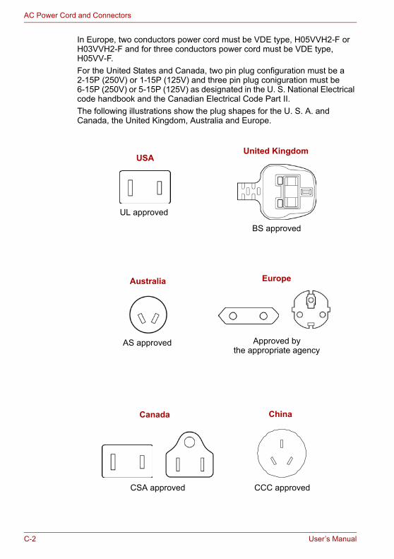
AC Power Cord and Connectors
In Europe, two conductors power cord must be VDE type, H05VVH2-F or H03VVH2-F and for three conductors power cord must be VDE type, H05VV-F.For the United States and Canada, two pin plug configuration must be a 2-15P (250V) or 1-15P (125V) and three pin plug coniguration must be 6-15P (250V) or 5-15P (125V) as designated in the U. S. National Electrical code handbook and the Canadian Electrical Code Part II.The following illustrations show the plug shapes for the U. S. A. and Canada, the United Kingdom, Australia and Europe.
USAUnited Kingdom
UL approved
BS approved
Australia
AS approved Approved by the appropriate agency
Canada
CSA approved
Europe
China
CCC approved
C-2 User’s Manual
Appendix D
If your computer is stolen
Should your computer be stolen, however, we’ll help you try to find it. Before contacting TOSHIBA, please prepare the following information which is necessary to uniquely identify your computer:■ In which country was your computer stolen?■ What type of machine do you have?■ What was the model number (PA number)?■ What was the serial number (8 digits)?■ When was it stolen, i.e. date?■ What is your address, phone, and fax number?
To register the theft on paper, please follow these procedures:■ Fill in the TOSHIBA Theft Registration form (or a copy of it) below.■ Attach a copy of your receipt showing where your computer was
purchased.■ Either fax or send the receipt and registration form to the address
below.
To register the theft online, please follow these procedures:■ Visit www.toshiba-europe.com on the Internet. In the product area,
choose Computer Systems. ■ In the Computer Systems page, open the Support & Downloads menu
and choose the Stolen Units Database option.Your entries are used to track your computer at our service points.
Always take care of your computer and try to prevent it from being stolen. You are the owner of a valuable technical device, which may be highly attractive to thieves, so please do not leave it unattended in a public place. To further help protect against theft, security cables can be bought for use with your notebook when it is being used at home or in the office.Make a note of your computer’s machine type, model number, and serial number, and put it in a safe place. You will find this information on the underside of your notebook. Please also keep the receipt of the computer you purchased.
User’s Manual D-1
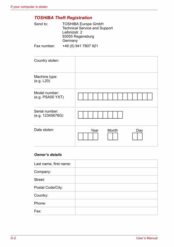
If your computer is stolen
TOSHIBA Theft RegistrationSend to: TOSHIBA Europe GmbH
Technical Service and SupportLeibnizstr. 293055 RegensburgGermany
Fax number: +49 (0) 941 7807 921
Owner’s details
Country stolen:
Machine type:(e.g. L20)
Model number:(e.g. PSA50 YXT)
Serial number:(e.g. 12345678G)
Date stolen:
Last name, first name:
Company:
Street:
Postal Code/City:
Country:
Phone:
Fax:
Year Month Day
D-2 User’s Manual
Glossary
The terms in this glossary cover topics related to this manual. Alternate naming is included for reference.
AbbreviationsAC: alternating currentAGP: accelerated graphics portASCII: American Standard Code for Information InterchangeBIOS: basic input output systemCD-ROM: Compact Disc-Read Only Memory CD-RW: Compact Disc-Read/WriteCMOS: complementary metal-oxide semiconductorCPU: central processing unitCRT: cathode ray tubeDC: direct currentDDC: display data channelDMA: direct memory accessDOS: disk operating systemDVD: digital versatile discECP: extended capabilities portFDD: floppy disk driveHDD: hard disk driveIDE: integrated drive electronicsI/O: input/outputIrDA: Infrared Data AssociationIRQ: interrupt requestKB: kilobyteLCD: liquid crystal displayLED: light emitting diodeLSI: large scale integrationMS-DOS: Microsoft Disk Operating SystemPCI: peripheral component interconnectRAM: random access memoryROM: read only memory
User’s Manual Glossary-1
Glossary
RTC: real time clockSCSI: small computer system interfaceTFT: thin-film transistorUSB: Universal Serial BusVESA: Video Electronic Standards AssociationVGA: video graphics array WXGA: wide extended graphics array
Aadaptor: A device that provides an interface between two dissimilar
electronic devices. For example, the AC adaptor modifies the power from a wall outlet for use by the computer. This term also refers to the add-in circuit cards that control external devices, such as video monitors and magnetic tape devices.
application: A group of programs that together are used for a specific task such as accounting, financial planning, spreadsheets, word processing and games.
ASCII: American Standard Code for Information Interchange. ASCII code is a set of 256 binary codes that represent the most commonly used letters, numbers, and symbols.
BBIOS: Basic Input Output System. The firmware that controls data flow
within the computer. See also firmware.bit: Derived from “binary digit,” the basic unit of information used by the
computer. It is either zero or one. Eight bits is one byte. See also byte.
boot: Short for bootstrap. A program that starts or restarts the computer. The program reads instructions from a storage device into the computer’s memory.
bps: Bits per second. Typically used to describe the data transmission speed of a modem.
buffer: The portion of the computer’s memory where data is temporarily stored. Buffers often compensate for differences in the rate of flow from one device to another.
bus: An interface for transmission of signals, data or electric power.byte: The representation of a single character. A sequence of eight bits
treated as a single unit; also the smallest addressable unit within the system.
C
Glossary-2 User’s Manual
Glossary
cache memory: High speed memory which stores data that increases processor speed and data transfer rate. When the CPU reads data from main memory, it stores a copy of this data in cache memory. The next time the CPU needs that same data, it looks for it in the cache memory rather than the main memory, which saves time. The computer has two cache levels. Level one is incorporated into the processor and level two resides in external memory.
capacity: The amount of data that can be stored on a magnetic storage device such as a floppy disk or hard disk. It is usually described in terms of kilobytes (KB), where one KB = 1024 bytes and megabytes (MB), where one MB = 1024 KB.
CardBus: An industry standard bus for 32-bit PC cards.CD-ROM: A Compact Disc-Read Only Memory is a high capacity disc that
can be read from but not written to. The CD-ROM drive uses a laser, rather than magnetic heads, to read data from the disc.
CD-R: A Compact Disc-Recordable disc can be written once and read many times. See also CD-ROM.
CD-RW: A Compact Disc-Read/Write disc can be rewritten many times. See also CD-ROM.
character: Any letter, number, punctuation mark, or symbol used by the computer. Also synonymous with byte.
chip: A small semiconductor containing computer logic and circuitry for processing, memory, input/output functions and controlling other chips.
CMOS: Complementary Metal-Oxide Semiconductor. An electronic circuit fabricated on a silicon wafer that requires very little power. Integrated circuits implemented in CMOS technology can be tightly packaged and are highly reliable.
compatibility: 1) The ability of one computer to accept and process data in the same manner as another computer without modifying the data or the media upon which it is being transferred. 2) the ability of one device to connect to or communicate with another system or component.
components: Elements or parts (of a system) which make up the whole (system).
configuration: The specific components in your system (such as the terminal, printer, and disk drives) and the settings that define how your system works. You use the HW Setup program to control your system configuration.
control keys: A key or sequence of keys you enter from the keyboard to initiate a particular function within a program.
controller: Built-in hardware and software that controls the functions of a specific internal or peripheral device (e.g. keyboard controller).
CPU: Central Processing Unit. The portion of the computer that interprets and executes instructions.
User’s Manual Glossary-3
Glossary
CRT: Cathode Ray Tube. A vacuum tube in which beams projected on a fluorescent screen-producing luminous spots. An example is the television set.
cursor: A small, blinking rectangle or line that indicates the current position on the display screen.
DDC: Direct Current. Electric current that flows in one direction. This type of
power is usually supplied by batteries.default: The parameter value automatically selected by the system when
you or the program do not provide instructions. Also called a preset value.
device driver: A program that controls communication between a specific peripheral device and the computer. The CONFIG.SYS file contains device drivers that MS-DOS loads when you turn the computer on.
dialog box: A window that accepts user input to make system settings or record other information.
disk drive: The device that randomly accesses information on a disk and copies it to the computer’s memory. It also writes data from memory to the disk. To accomplish these tasks, the unit physically rotates the disk at high speed past a read-write head.
display: A CRT, LCD, or other image producing device used to view computer output.
DOS: Disk Operating System. See operating system.driver: A software program, generally part of the operating system, that
controls a specific piece of hardware (frequently a peripheral device such as a printer or mouse).
DVD-RAM: A Digital Versatile Disc Random Access Memory is a high-capacity, high performance disc that lets you store large volumes of data. The DVD-ROM drive uses a laser to read data from the disc.
DVD-ROM: A Digital Versatile Disc Read Only Memory is a high capacity, high performance disc suitable for play back of video and other high-density files. The DVD-ROM drive uses a laser to read data from the disc.
Eexecute: To interpret and execute an instruction.
Ffloppy disk: A removable disk that stores magnetically encoded data.
Glossary-4 User’s Manual
Glossary
floppy disk drive (FDD): An electromechanical device that reads and writes to floppy disks.
folder: An icon in Windows used to store documents or other folders.format: The process of readying a blank disk for its first use. Formatting
establishes the structure of the disk that the operating system expects before it writes files or programs onto the disk.
function keys: The keys labeled F1 through F12 that tell the computer to perform certain functions.
Ggigabyte (GB): A unit of data storage equal to 1024 megabytes. See also
megabyte.graphics: Drawings, pictures, or other images, such as charts or graphs,
to present information.
Hhard disk: A non-removable disk usually referred to as drive C. The
factory installs this disk and only a trained engineer can remove it for servicing. Also called fixed disk.
hard disk drive (HDD): An electromechanical device that reads and writes a hard disk. See also hard disk.
hertz: A unit of wave frequency that equals one cycle per second.hot key: The computer’s feature in which certain keys in combination with
the extended function key, Fn, can be used to set system parameters, such as speaker volume.
Ii.LINK (IEEE1394): This port enables high-speed data transfer directly
from external devices such as digital video cameras.input: The data or instructions you provide to a computer, communication
device or other peripheral device from the keyboard or external or internal storage devices. The data sent (or output) by the sending computer is input for the receiving computer.
interface: 1) Hardware and/or software components of a system used specifically to connect one system or device to another. 2) To physically connect one system or device to another to exchange information. 3) The point of contact between user, the computer, and the program, for example, the keyboard or a menu.
I/O: Input/output. Refers to acceptance and transfer of data to and from a computer.
I/O devices: Equipment used to communicate with the computer and transfer data to and from it.
User’s Manual Glossary-5
Glossary
IrDA 1.1: An industry standard that enables cableless infrared serial data transfer at speeds of up to 4 Mbps.
Jjumper: A small clip or wire that allows you to change the hardware
characteristics by electrically connecting two points of a circuit.
KK: Taken from the Greek word kilo, meaning 1000; often used as
equivalent to 1024, or 2 raised to the 10th power. See also byte and kilobyte.
KB: See kilobyte.
LLight Emitting Diode (LED): A semiconductor device that emits light
when a current is applied.Liquid Crystal Display (LCD): Liquid crystal sealed between two sheets
of glass coated with transparent conducting material. The viewing-side coating is etched into character forming segments with leads that extend to the edge of the glass. Applying a voltage between the glass sheets alters the brightness of the liquid crystal.
LSI: Large Scale Integration. 1) A technology that allows the inclusion of up to 100,000 simple logic gates on a single chip. 2) An integrated circuit that uses large scale integration.
Mmegabyte (MB): A unit of data storage equal to 1024 kilobytes. See also
kilobyte.mode: A method of operation, for example, the boot mode, standby mode
or the hibernation mode.modem: Derived from modulator/demodulator, a device that converts
(modulates) digital data for transmission over telephone lines and then converts modulated data (demodulates) to digital format where received.
monitor: A device that uses rows and columns of pixels to display alphanumeric characters or graphic images. See also CRT.
MP3: An audio compression standard that enables high-quality transmission and real-time playback of sound files.
N
Glossary-6 User’s Manual
Glossary
numeric keypad overlay: A feature that allows you to use certain keys on the keyboard to perform numeric entry, or to control cursor and page movement.
Ooperating system: A group of programs that controls the basic operation
of a computer. Operating system functions include interpreting programs, creating data files, and controlling the transmission and receipt (input/output) of data to and from memory and peripheral devices.
output: The results of a computer operation. Output commonly indicates data. 1) printed on paper, 2) displayed at a terminal, 3) sent through the serial port of internal modem, or 4) stored on some magnetic media.
Pparity: 1) The symmetrical relationship between two parameter values
(integers) both of which are either on or off; odd or even; 0 or 1. 2) In serial communications, an error detection bit that is added to a group of data bits making the sum of the bits even or odd. Parity can be set to none, odd, or even.
peripheral device: An I/O device that is external to the central processor and/or main memory such as a printer or a mouse.
pixel: A picture element. The smallest dot that can be made on a display or printer. Also called a pel.
plug and play: A capability with Windows that enables the system to automatically recognize connections of external devices and make the necessary configurations in the computer.
port: The electrical connection through which the computer sends and receives data to and from devices or other computers.
prompt: A message the computer provides indicating it is ready for or requires information or an action from you.
RRandom Access Memory (RAM): High speed memory within the
computer circuitry that can be read or written to.restart: Resetting a computer without turning it off (also called “warm
boot” or “soft reset”). See also boot.RJ11: A modular telephone jack.RJ45: A modular LAN jack.ROM: Read Only Memory: A nonvolatile memory chip manufactured to
contain information that controls the computer’s basic operation. You cannot access or change information stored in ROM.
User’s Manual Glossary-7
Glossary
SSCSI: Small Computer System Interface is an industry standard interface
for connection of a variety of peripheral devices.soft key: Key combinations that emulate keys on the IBM keyboard,
change some configuration options, stop program execution, and access the numeric keypad overlay.
stop bit: One or more bits of a byte that follow the transmitted character or group codes in asynchronous serial communications.
system disk: A disk that has been formatted with an operating system. For MS-DOS the operating system is contained in two hidden files and the COMMAND.COM file. You can boot a computer using a system disk. Also called an operating system disk.
Tterminal: A typewriter-like keyboard and CRT display screen connected to
the computer for data input/output.TFT display: A liquid crystal display (LCD) made from an array of liquid
crystal cells using active-matrix technology with thin film transistor (TFT) to drive each cell.
TouchPad: A pointing device integrated into the TOSHIBA computer palm rest.
UUniversal Serial Bus: This serial interface lets you communicate with
several devices connected in a chain to a single port on the computer.
VVGA: Video Graphics Array is an industry standard video adaptor that lets
you run any popular software.
Wwarm start: Restarting or resetting a computer without turning it off.write protection: A method for protecting a floppy disk from accidental
erasure.
Glossary-8 User’s Manual