SATELLITE BEAM HANDOVER STRATEGY TO IMPROVE RETURN · PDF fileSATELLITE BEAM HANDOVER STRATEGY...
12
International Journal of Wireless & Mobile Networks (IJWMN) Vol. 3, No. 5, October 2011 DOI : 10.5121/ijwmn.2011.3509 113 SATELLITE BEAM HANDOVER STRATEGY TO IMPROVE RETURN LINK RESOURCE UTILIZATION Jinyoung Jang 1 , Minwoo Lee 1 , Eunkyung Kim 1 and Jaesung Lim 2 1 Department of Network Centric Warfare, Graduate school of Ajou University, SuWon, South Korea [email protected], [email protected], [email protected] 2 Jangwee Research Institute for National Defence, Graduate school of Ajou University, SuWon, South Korea [email protected] ABSTRACT Mobile communication on the multi-beam satellite communication has attracted attention, since Digital Video Broadcasting – Return Channel Satellite (DVB-RCS) has been successively implemented. In general, multi beam satellite employs uniform allocation of RF power and bandwidth to multi beams, since it is hard to predict the distribution of traffic requests and the arrival rate of new connection. This makes it difficult to satisfy the traffic requests in a beam. Thus, when an unpredictable event, such as a disaster, regional warfare and deteriorating weather conditions, occur in a special spot beam, many more terminals will require access to a special beam channel. This causes the special beam channel to be saturated, while adjacent beam channel resources are available. Thus, we propose a novel handover strategy to improve satellite return link resource utilization using load balancing handover. Simulation results shows the proposed handover algorithm outperforms conventional handover algorithms in terms of new connection block probability, handover block probability, return link resource utilization and capacity request block rate. KEY WORDS Satellite beam handover, DVB-RCS, return link resource utilization, Load balancing 1. INTRODUCTION Satellite communication system is essential to the maritime and aerospace environment, where infrastructure is not established. Only satellite communication can support broadband network service to maritime terminals, such as merchant ships, naval vessels, maritime platforms and fishing boats. A global beam satellite system could support a wide range of services. However, the transmission power of a satellite is distributed as widely as the service region. Thus, the power density decreases, according to the service region. Thus multi spot beam satellite is attractive in terms of improving power flux density, system capacity and spectral efficiency[1]. If a terminal moves to another spot beam, a handover will occur between the two beams in the satellite system. In this case, handover detection should be considered. Traditionally, handover detection is based on the RSS (Received Signal Strength) measurement to guarantee QoS (Quality of Service) in the terrestrial cellular communication system. However, there is
Transcript of SATELLITE BEAM HANDOVER STRATEGY TO IMPROVE RETURN · PDF fileSATELLITE BEAM HANDOVER STRATEGY...

International Journal of Wireless & Mobile Networks (IJWMN) Vol. 3, No. 5, October 2011
DOI : 10.5121/ijwmn.2011.3509 113
SATELLITE BEAM HANDOVER STRATEGY TO
IMPROVE RETURN LINK RESOURCE UTILIZATION
Jinyoung Jang1, Minwoo Lee
1, Eunkyung Kim
1 and Jaesung Lim
2
1Department of Network Centric Warfare, Graduate school of Ajou University,
SuWon, South Korea [email protected], [email protected], [email protected]
2Jangwee Research Institute for National Defence, Graduate school of Ajou University,
SuWon, South Korea [email protected]
ABSTRACT
Mobile communication on the multi-beam satellite communication has attracted attention, since
Digital Video Broadcasting – Return Channel Satellite (DVB-RCS) has been successively implemented.
In general, multi beam satellite employs uniform allocation of RF power and bandwidth to multi beams,
since it is hard to predict the distribution of traffic requests and the arrival rate of new connection. This
makes it difficult to satisfy the traffic requests in a beam. Thus, when an unpredictable event, such as a
disaster, regional warfare and deteriorating weather conditions, occur in a special spot beam, many
more terminals will require access to a special beam channel. This causes the special beam channel to
be saturated, while adjacent beam channel resources are available. Thus, we propose a novel handover
strategy to improve satellite return link resource utilization using load balancing handover. Simulation
results shows the proposed handover algorithm outperforms conventional handover algorithms in terms
of new connection block probability, handover block probability, return link resource utilization and
capacity request block rate.
KEY WORDS
Satellite beam handover, DVB-RCS, return link resource utilization, Load balancing
1. INTRODUCTION
Satellite communication system is essential to the maritime and aerospace environment,
where infrastructure is not established. Only satellite communication can support broadband
network service to maritime terminals, such as merchant ships, naval vessels, maritime
platforms and fishing boats.
A global beam satellite system could support a wide range of services. However, the
transmission power of a satellite is distributed as widely as the service region. Thus, the power
density decreases, according to the service region. Thus multi spot beam satellite is attractive
in terms of improving power flux density, system capacity and spectral efficiency[1].
If a terminal moves to another spot beam, a handover will occur between the two beams in
the satellite system. In this case, handover detection should be considered. Traditionally,
handover detection is based on the RSS (Received Signal Strength) measurement to guarantee
QoS (Quality of Service) in the terrestrial cellular communication system. However, there is
International Journal of Wireless & Mobile Networks (IJWMN) Vol. 3, No. 5, October 2011
114
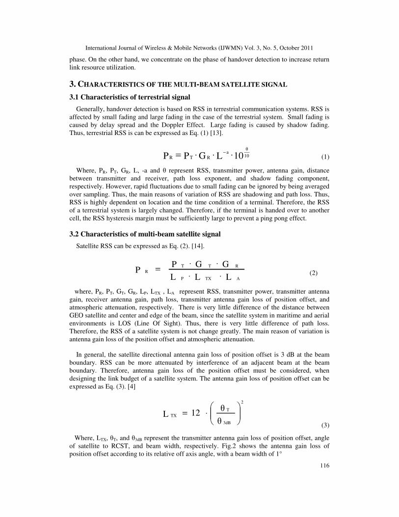
little difference in RSSs between the centre and the boundary of a satellite beam, whereas a
terrestrial communication system has RSS noticeable differences. The satellite RSS can be
changed by antenna gain loss and atmospheric attenuation or a jamming signal. A spot beam is
divided into high beam area and low beam area due to the rain attenuation margin. The position
based handover detection approach is suggested in the DVB-RCS standard as a baseline, since
RSS of an adjacent beam is not severely different.
In general, multi beam satellite employs uniform allocation of RF power and bandwidth to
multi beams, since it is hard to predict the distribution of traffic requests and arrival rate of
new connections. Also, heterogeneous allocation of RF power and bandwidth to multi beams
can cause channel interference to adjacent beams. Thus, satellite does not have sufficient
flexibility to satisfy the traffic requests on a beam. When an unpredictable event, such as a
disaster, regional warfare and deteriorating weather conditions, occur in a special spot beam, it
is important to ensure a new connection to the satellite channel[2][3]. However, if many
terminals require access to the special beam channel, the speci2l beam channel will be
saturated and new connection request will be blocked, while adjacent beam channel resource is
available. Even though a new connection request is unpredictable, a handover request can be
predicted. Therefore, if the resource utilization of a special beam is exceeds that of the adjacent
beam, NCC (Network Control Centre) can recommend terminals that are in the low beam area
of the adjacent beam to handover to the adjacent beam, to prevent saturation of the special
beam resource. Thus, we propose a load balancing handover strategy that increases satellite
return link resource utilization.
The remainder of this paper is organized as follows. Section 2 describes the background of
the DVB-RCS and related work on the handover detection algorithm. Section 3 describes
characteristics of multi-beam satellite signals. Section 4 presents the proposed load balancing
handover strategy. Section 5 presents simulation results. Finally, we conclude this paper in
Section 6.
2. BACKGROUND AND RELATED WORK
2.1 DVB-RCS handover strategy
The DVB-RCS standard is set up to support mobility of RCST, and proposed the process of
beam handover. The handover strategy is processed in three phases, as follows. First phase:
Handover detection determines the necessity for the mobile RCST to be handed over, and
typically also determines a list of candidate beams. The position based handover detection
approach is suggested in the standard as a baseline. The handover detection process can be
distributed by RCST or centralized by NCC. Second phase: the handover decision phase
selecting the target beam to be handed over, considering the candidate beam resource, and
issues handover command. Third phase: the handover execution hands over RCST from a set
of resources in the current beam to another set of resources allocated in the target beam [4].
Position based spot beam handover is suited to the DVB-RCS system, because position
information is already a requisite in mobile DVB-RCS. RCST uses the SAC (satellite access
control) field in SYNC slot to request capacity, send CSI (channel state information) and
mobility control messages to NCC. RCSTs periodically send a SYNC burst every super frame
[5][6]. A RCST monitors its own position or RSS (received signal strength) to detect the
handover necessity. The RCST sends a handover request message to the NCC when handover
is detected. This is the distributed handover detection approach. Otherwise, a centralized
handover detection approach, in which all processing is done in the NCC, is used. Then, NCC
makes the handover decision. Handover execution is initialized after the handover decision

International Journal of Wireless & Mobile Networks (IJWMN) Vol. 3, No. 5, October 2011
115
processes. NCC sends the handover command to the RCST with information about the target
beam to be used. Fig.1 shows the overall DVB-RCS beam handover process.
Fig. 1. DVB-RCS handover process
2.2 Handover detection algorithm
Traditional handover detection algorithms are based on the RSS measurement. Hysteresis
margin and RSS threshold are used to prevent the ping-pong effect. The authors in [7]
proposed the adaptive handover algorithm for a multi-beam GEO satellite. They proposed a
sampling algorithm and adaptive handover algorithm. The amount of RSS sampling is
determined by the velocity of a terminal in the RSS sampling algorithm. The RSS hysteresis
margin is determined adaptively by sampling measurement and velocity of a terminal in the
adaptive handover algorithm. This algorithm shows that the hysteresis margin decreases when
RSS measurements decrease and the terminal velocity is faster. The authors in [8] proposed the
adaptive handover algorithm based on distance information. The RSS hysteresis margin is
determined adaptively by the distance between the MS (Mobile Station) and the serving BS
(Base Station). This algorithm shows that the MS position is close to the cell radius, the
hysteresis margin decreases, so as to easily handover trigger. If the distance between the MS
and the serving BS is equal to the cell radius, the hysteresis margin becomes zero. The authors
in [9] proposed the adaptive handover algorithm based on RCST mobility information. This
algorithm shows the better handover performance in the rain sky and shows the better forward
link resource utilization.
2.3 Handover decision / execution algorithm
The authors in [10][11] proposed DVB-RCS handover scheme for supporting handover
decision. After handover detection, if target beam resources are enough to support to handover,
handovers immediately decided. However, if not, handover request may be queued. Handover
decisions that rely on exclusively on position information without any prioritization strategy
may lead to high handover failure rates. So they classified of a RCST such as aircraft, high-
speed train by the velocity. RCSTs estimate of residual time of current spot beam by using of a
target beam approach velocity (TBAV) and a distance of beam edge. handover request is
prioritized by the NCC according to the residence time value. This handover decision
algorithm shows that lower handover failure probability and higher new connection blocking
probability. The authors in [12] proposed handover execution algorithm. They pay attention to
the process of after handover decision. After handover decision, NCC sends a TIM (terminal
information table) message to the RCST. If TIM message is lost, handover execution will be
fail. So they proposed the NCC with memory for the lower the handover failure probability.
Briefly, the prior researches only pay attention to the after position based handover detection
International Journal of Wireless & Mobile Networks (IJWMN) Vol. 3, No. 5, October 2011
116
phase. On the other hand, we concentrate on the phase of handover detection to increase return
link resource utilization.
3. CHARACTERISTICS OF THE MULTI-BEAM SATELLITE SIGNAL
3.1 Characteristics of terrestrial signal
Generally, handover detection is based on RSS in terrestrial communication systems. RSS is
affected by small fading and large fading in the case of the terrestrial system. Small fading is
caused by delay spread and the Doppler Effect. Large fading is caused by shadow fading.
Thus, terrestrial RSS is can be expressed as Eq. (1) [13].
10LGPP 10
θa
RTR ⋅⋅⋅= −
(1)
Where, PR, PT, GR, L, -a and θ represent RSS, transmitter power, antenna gain, distance
between transmitter and receiver, path loss exponent, and shadow fading component,
respectively. However, rapid fluctuations due to small fading can be ignored by being averaged
over sampling. Thus, the main reasons of variation of RSS are shadowing and path loss. Thus,
RSS is highly dependent on location and the time condition of a terminal. Therefore, the RSS
of a terrestrial system is largely changed. Therefore, if the terminal is handed over to another
cell, the RSS hysteresis margin must be sufficiently large to prevent a ping pong effect.
3.2 Characteristics of multi-beam satellite signal
Satellite RSS can be expressed as Eq. (2). [14].
LLL
GGPP
ATXP
RTT
R
⋅⋅
⋅⋅=
(2)
where, PR, PT, GT, GR, LP, LTX , LA represent RSS, transmitter power, transmitter antenna
gain, receiver antenna gain, path loss, transmitter antenna gain loss of position offset, and
atmospheric attenuation, respectively. There is very little difference of the distance between
GEO satellite and center and edge of the beam, since the satellite system in maritime and aerial
environments is LOS (Line Of Sight). Thus, there is very little difference of path loss.
Therefore, the RSS of a satellite system is not change greatly. The main reason of variation is
antenna gain loss of the position offset and atmospheric attenuation.
In general, the satellite directional antenna gain loss of position offset is 3 dB at the beam
boundary. RSS can be more attenuated by interference of an adjacent beam at the beam
boundary. Therefore, antenna gain loss of the position offset must be considered, when
designing the link budget of a satellite system. The antenna gain loss of position offset can be
expressed as Eq. (3). [4]
⋅=θ
θ12L
3dB
T
2
TX
(3)
Where, LTX, θT, and θ3dB represent the transmitter antenna gain loss of position offset, angle
of satellite to RCST, and beam width, respectively. Fig.2 shows the antenna gain loss of
position offset according to its relative off axis angle, with a beam width of 1°

International Journal of Wireless & Mobile Networks (IJWMN) Vol. 3, No. 5, October 2011
117
Fig. 2. Antenna gain loss of position offset Fig. 3. Spot beam arrangement
The second variation factor is Atmospheric attenuation. This atmospheric attenuation is
highly time dependent. Generally, atmospheric attenuation is very small (e.g. 0.2dB). However,
when it is raining, satellite RSS is severely influenced by rain attenuation at the ku, ka band
(e.g. 5dB). Thus, a satellite system is designed to overcome rain attenuation. Accordingly, the
spot beam is divided into a high beam area and a low beam area, as in Fig.3.
If CCM (Constant Coding and Modulation) is applied to a satellite system in clear
conditions, satellite communication is guaranteed in the low beam area caused by the rain
attenuation margin. DVB-S2 has recently applied the ACM (Adaptive Coding and
Modulation) to increase resource utilization. Thus, even if handover detection is delayed in the
low beam area, the QoS of satellite communication could be guaranteed. However, the overall
spectral efficiency will be degraded.
4. LOAD BALANCING HANDOVER STRATEGY
The special spot beam channel will be saturated, if there are many unexpected new
connection requests to the special spot beam channel, while the adjacent beam channel
resource is available.
This blocks the new connection request and the handover request to the special spot beam.
However, a mobile terminal that is in the region of adjacent low beam boundary could be
guaranteed QoS, even if handed over to the adjacent beam. Thus, we can prevent saturation of
special spot beam resource by handing over mobile terminal to the adjacent beam when
saturation of the special spot beam resource occurs, while adjacent beam resource is available
and the mobile terminal is in the low beam boundary of adjacent beam. That is, we can
balance loads by handing over the mobile terminal. Thus, we proposed the load balancing
handover strategy.
Fig. 4. Proposed handover strategy
International Journal of Wireless & Mobile Networks (IJWMN) Vol. 3, No. 5, October 2011
118
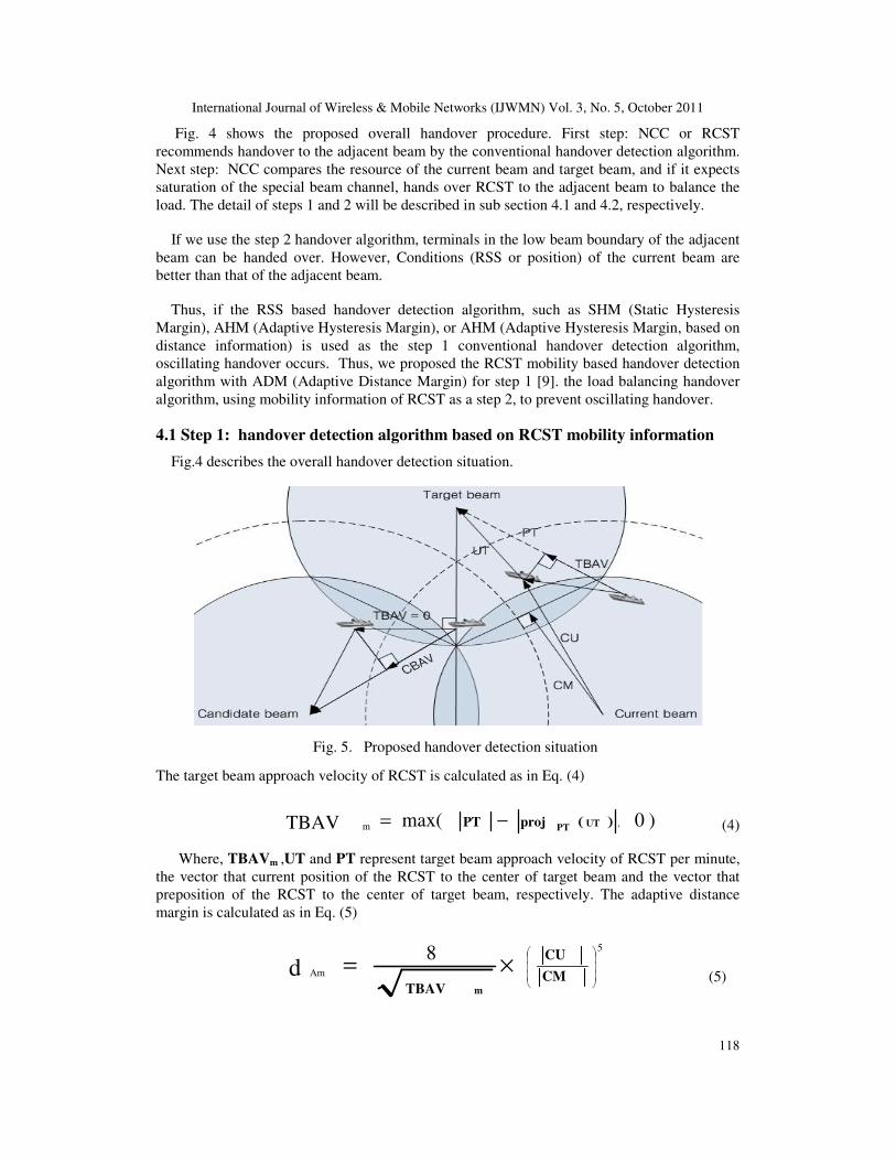
Fig. 4 shows the proposed overall handover procedure. First step: NCC or RCST
recommends handover to the adjacent beam by the conventional handover detection algorithm.
Next step: NCC compares the resource of the current beam and target beam, and if it expects
saturation of the special beam channel, hands over RCST to the adjacent beam to balance the
load. The detail of steps 1 and 2 will be described in sub section 4.1 and 4.2, respectively.
If we use the step 2 handover algorithm, terminals in the low beam boundary of the adjacent
beam can be handed over. However, Conditions (RSS or position) of the current beam are
better than that of the adjacent beam.
Thus, if the RSS based handover detection algorithm, such as SHM (Static Hysteresis
Margin), AHM (Adaptive Hysteresis Margin), or AHM (Adaptive Hysteresis Margin, based on
distance information) is used as the step 1 conventional handover detection algorithm,
oscillating handover occurs. Thus, we proposed the RCST mobility based handover detection
algorithm with ADM (Adaptive Distance Margin) for step 1 [9]. the load balancing handover
algorithm, using mobility information of RCST as a step 2, to prevent oscillating handover.
4.1 Step 1: handover detection algorithm based on RCST mobility information
Fig.4 describes the overall handover detection situation.
Fig. 5. Proposed handover detection situation
The target beam approach velocity of RCST is calculated as in Eq. (4)
( ) )0max(TBAV ,m UTPTprojPT −= (4)
Where, TBAVm ,UT and PT represent target beam approach velocity of RCST per minute,
the vector that current position of the RCST to the center of target beam and the vector that
preposition of the RCST to the center of target beam, respectively. The adaptive distance
margin is calculated as in Eq. (5)
×=CM
CU
TBAV m
5
Am
8d (5)

International Journal of Wireless & Mobile Networks (IJWMN) Vol. 3, No. 5, October 2011
119
The distance margin adaptively adjusted by position of the RCST and TBAV using Eq.
(5). Where dAm, and CU, CM represent adaptive distance margin, the vector that is the center
of the current beam to the current position of the RCST, and the vector that is the center of the
current beam to the middle point between the current beam and the target beam center.
Fig. 6. Overall handover detection procedure
Fig.6. shows that the overall handover detection procedure. The Log on RCST measures the
channel state. If the channel state is lower than the link degradation threshold, RCST may log
out, or RCST ranks the adjacent beams in order of the closest distance from the beam center.
Then, it selects the first ranked adjacent beam as a target beam, and the next ranked beam as a
candidate beam. Next, RCST or NCC performs the Adaptive handover detection algorithm
based on RCST mobility information. If the current beam distance (UBD) is greater than the
sum of the target beam distance (TBD) and the adaptive distance margin (ADM), RCST is
handed over to the target beam. However, if the RCST is not in the current high beam
boundary but in the target high beam boundary, and RCST is moving away from the target
beam center, as a Fig.5. Then, handover detection is delayed until the target beam is changed.
This increases the link degradation rate or lowers resource utilization. Thus, it is desirable that
it considers candidate beam handover. If the UBD is greater than the sum of candidate beam
distance (CBD) and ADM, RCST is handed over to the candidate beam.
4.2 Step 2: Handover algorithm for load balancing
It is hard to predict the distribution of the traffic request and the new connection arrival.
Conversely, the handover request of terminals can be predicted. The RCST that is closer and
approaches the target beam faster is more likely to be handed over to the target beam.
It is desirable that handover RCST, which is the most expected handover to the adjacent
beam, in the process of step 2. This means that terminals are handed over in advance to balance
loads. Thus, we proposed a LDM (Load balancing Distance Margin) concept to select the
anticipated handover terminal.

International Journal of Wireless & Mobile Networks (IJWMN) Vol. 3, No. 5, October 2011
120
CU
UT2
m
TBAV
1 LDM ×= (6)
As the RCST is closer and approaches to the target beam faster, LDM is going to be smaller
to be easily handed over to the target beam. The LDM of RCST is calculated as in Eq. (6)
36000180
12margin)Rain (3 tan LBD 3 ×
×+=
π
θdB
(7)
The LBD (Low Beam boundary distance) is calculated as in Eq. (7) from Eq. (3). If RCSTs
are in the LBD of the adjacent beam under a clear sky, RCST can be serviced without link
degradation.
Fig. 7. Overall handover for the load balancing procedure
Fig. 7. shows that the overall handover process for the load balancing procedure. If CBR
(Current Beam Resource) is greater than the sum of TBR (Target Beam Resource) and RM
(Resource Margin), NCC tries to balance loads. If the LDM of terminal is smaller than LBD,
RCST is handed over to the target beam. RM is necessary to prevent the back and forth
handover caused by load balancing handover.
Load balancing of multi beams is achieved by handing over the anticipated handover RCST
in advance. Furthermore, oscillating handover does not occur, because it is considered by
TBAV in the step1 and step 2 algorithms.
5. SIMULATION RESULTS
This section evaluates performances of the proposed handover strategy in terms of new
connection block probability, handover block probability, return link resource utilization,
handover rate and link degradation rate. Simulation is done based on matlab ver 7.0.4.
Simulations show the proposed load balancing handover strategy achieved better performance
than conventional handover strategy did. Table 1 lists the simulation parameters.

International Journal of Wireless & Mobile Networks (IJWMN) Vol. 3, No. 5, October 2011
121
Table 1 Simulation parameters
parameters value
Simulation time 10hour
Number of beams 3
Beam width 0.5° Fixed Capacity Allocation per beam 128 slot
Capacity request per RCST 1 ~ 5 slot
Resource margin 12 slot
Initially number of RCST 90
Velocity of RCST 6 ~ 1000kmph
Course change rate of RCST 5° ~ 15° / 15min
Average service time 5hour
Threshold of link degradation -126.8085dB
Rain attenuation margin 5dB
We assumed that the FCA (Fixed Capacity Allocation) per beam is 128 slots. The new
connection arrival process in each beam is Poisson with rate λ. The average service time is
exponentially distributed with a mean of 5 hours. The load balancing handover resource
margin is 12 slots, 90 RCST is initially distributed uniformly in each beam. We concentrate on
the effectiveness of load balancing handover. Performance is compared to the conventional
handover algorithm without load balancing handover and the proposed handover strategy using
LDM. Conventional handover algorithms achieved similar performance from the viewpoint of
resource utilization. Whereas, proposed handover strategy achieved better performance. The
proposed strategy not only serviced more RCSTs, but also achieved better QoS per RCST.
Fig. 8. Handover rate vs. λ Fig. 9. Link degradation rate vs. λ Fig. 8 shows the handover rate versus the new connection arrival rate[λ]. Handover rate
decreases with increasing λ, as the available resources of a spot beam decrease with increases
in the new connection arrival. The handover rate of the proposed algorithm, LDM, is greater
than that of conventional handover algorithms that do not apply a load balancing strategy Due
to the step 2 handover procedure of the LDM scheme to balance loads after the conventional
handover procedure. Therefore, the proposed handover strategy has a disadvantage from the
viewpoint of the handover rate.

International Journal of Wireless & Mobile Networks (IJWMN) Vol. 3, No. 5, October 2011
122
However, the Return link resource utilization, service rate and QoS per RCST are greater.
Fig.9. shows the link degradation rate according to the new connection arrival rate [λ]. As λ
increased, the link degradation rate increased. LDM shows the lowest link degradation rate
until the new connection rate was 5.6. If the channel condition of the terminal is out of the link
degradation threshold, the terminal is logged out. Therefore, terminals must be handed over to
the target beam before link degradation occurs. Especially, a fast terminal has a short time until
the link degradation worsens. If the handover request is blocked due to the shortage of target
beam resource, and the handover does not succeed until the link degradation worsens, the
terminal is logged out. The lowest link degradation rate is achieved at the LDM using target
beam approach velocity in step 1and step 2.
Fig. 10. Satellite system utilization vs. λ Fig. 11. Handover block rate vs. λ
Fig.10 shows the satellite system utilization [ρ=λ/µ] based on the new connection arrival
rate. A new connection arrival rate above 5.6 overflows the satellite system. So plots higher
than λ = 5.6 are meaningless. This result shows that the proposed handover strategy achieved a
better service rate [µ]. That is, more RCSTs were serviced by the satellite when we applied
LDM. Fig.11 and Fig.12 show the handover block rate and new connection block rate,
respectively. LDM achieves that the lowest handover rate and new connection rate, according
to the new connection arrival rate. Other schemes show similar performance. They do not
apply the step 2 load balancing handover. Thus, the special spot beam channel can be saturated,
while the adjacent spot beam channel is available. Whereas, saturation of the special spot beam
channel is prevented by step 2 load balancing handover at the LDM.
Fig. 12. New connection block rate vs. λ Fig. 13. Return link resource utilization vs.λ

International Journal of Wireless & Mobile Networks (IJWMN) Vol. 3, No. 5, October 2011
123
Fig.13 shows the return link resource utilization according to the new connection arrival rate.
RCSTs request the resource used in the return link, by transmitting the CR (Capacity request)
message within the SAC field. NCC allocates the return link capacity to the RCST. Extra
resource is allocated to RCSTs by FCA (Free Capacity assignment) strategy, if the return link
resource remains after allocation of the CR. In the opposite case, the CR of RCSTs is blocked.
This lowers QoS. As the new connection arrival rate increases, total return link utilization
increases. LDM shows the highest return link resource utilization. This means that the
remainder of the resource is lower after capacity allocation. This result is caused by the low
new connection block rate and link degradation rate
Fig. 14. Capacity request block rate vs. λ Fig.14 shows the capacity request block rate versus the new connection arrival rate. As the
new connection arrival rate increases, the capacity request block rate increases. LDM achieves
the lowest capacity block rate. This means that CR is more allocated at the LDM than other
schemes. This result shows that the QoS of a RCST is further guaranteed by step 2 load
balancing handover.
6. CONCLUSION
The DVB-RCS standard is evolving and was released to support terminal mobility. Mobility
and resource management are key issues of a satellite system. NCC manages the resource of
each beam and can know mobility information of all RCSTs. If the distribution of traffic and
RCST at each beam differs, that is, if the resource utilization of each beam differs, it is
possible to achieve the load balancing effect by RCST handover in advance, which is expected
to handover to the adjacent beam. Thus, we proposed the spot beam handover strategy to
increase return link resource utilization.
The RSS based conventional handover scheme causes oscillating handover, if we apply it to
load balancing handover. Therefore, we consider TBAV for the conventional and load
balancing handover algorithm to prevent a ping pong effect.
Simulations show low link degradation and a new connection block rate are achieved using
our proposed algorithm. This increases return link resource utilization. Furthermore, a low
capacity request block rate is achieved. Thus, more RCSTs can be serviced and the QoS of a
RCST is increased by load balancing handover.

International Journal of Wireless & Mobile Networks (IJWMN) Vol. 3, No. 5, October 2011
124
ACKNOWLEDGMENT
This research was supported by the MKE (The Ministry of Knowledge Economy), Korea,
under the ITRC (Information Technology Research Center) support program supervised by the
NIPA (National IT Industry Promotion Agency” (NIPA-2011-(C1090-1121-0011))
REFERENCES
[1] Ray E. Sheriff and Y. Fun Hu : Mobile Satellite Communication Networks
[2] X. Alberti, J.M. Cebrian : System Capacity Optimization in Time and Frequency for Multibeam
Multi-Media Satellite Systems, ASMS-SPSC 2010, 226-233
[3] Katsuya Nakahira, Kiyoshi Kobayashi and Masazumi Ueba, Capacity and Quality Enhancement
using an Adaptive Resource Allocation for Multi-beam Mobile Satellite Communication,
WCNC 2006, 153-158
[4] ETSI TR 102 768 V1.1.1 (2009-04), Digital Video Broadcasting (DVB) ; Interaction channel for
Satellite Distribution Systems ; Guideline for the use of En 301 790 in mobile scenarios
[5] ETSI EN 301 768 V1.5.1 (2009-05), Digital Video Broadcasting (DVB) ; Intersection channel
for Satellite Distribution Systems
[6] A. Iuoras and C. Morlet : Network and Mobility Management for mobile DVB-S2/DVB-RCS
systems, IWSSC 2007, 264-268.
[7] F Li Song, Ai-jun Liu and Yi-fei Ma : Adaptive handover algorithm for multi-beam GEO mobile
satellite system, ICC 2008, 1947-1951,
[8] Huamin Zhu and Kyung-sup Kwak : Performance analysis of an adaptive handover algorithm
based on distance information, computer communications 30(2007), 1278-1288,
[9] Jinyong Jang, Minwoo Lee and Eunkyung Kim : Satellite beam handover detection algorithm
based on RCST mobility information, WASET 2011,779-785
[10] Fabio Lattanzi, Guray Acar and Barry Evans : DVB-RCS spotbeam handover using residence
time estimation in vehicular satellite network, 4th ASMS 2008, 235-239.
[11] Fabio Lattanzi, Guray Acar and Barry Evans : Performance study of a lightweight DVB-RCS
handover scheme for vehicular GEO Networks, IWSSC 2008
[12] Guray Acar, Paris Skoutaridis, Christos Kasparis and Barry Evans : position-based DVB-RCS
spotbeam handover in vehicular Geostationary satellite networks, VTC spring 2007, 1410-1414
[13] Tae Chul Hong, Kun Seok Kang, Do-Seob Ahn and Ho-Jin Lee : Inter- System Handover
Analysis in Integrated Terrestrial and GEO satellite Communication Networks for Seamless
Mobility, 9th ACT 2007, 717-721
[14] Anil K. Maini and Varsha Agrawal : satellite Technology principles and applications 2007
[15] Syed S.Rizvi, Aasia Riasat and Khaled M. Elleithy : A Quantitative Analysis of Handover Time
at MAC Layer for Wireless Mobile Networks, IJWMN 2009,vol 2,no.1, 21-28