Satellite A210 User's Manual - Toshiba...
276
TOSHIBA Satellite A210/ Satellite Pro A210 Portable Personal Computer User’s Manual
Transcript of Satellite A210 User's Manual - Toshiba...

TOSHIBA Satellite A210/Satellite Pro A210
Portable Personal ComputerUser’s Manual
Copyright© 2007 by TOSHIBA Corporation. All rights reserved. Under the copyright laws, this manual cannot be reproduced in any form without the prior written permission of TOSHIBA. No patent liability is assumed, with respect to the use of the information contained herein.TOSHIBA Satellite A210/Satellite Pro A210 Portable Personal Computer User’s ManualFirst edition August 2007Copyright authority for music, movies, computer programs, data bases and other intellectual property covered by copyright laws belongs to the author or to the copyright owner. Copyrighted material can be reproduced only for personal use or use within the home. Any other use beyond that stipulated above (including con-version to digital format, alteration, transfer of copied material and distribution on a network) without the permission of the copyright owner is a violation of copy-right or author’s rights and is subject to civil damages or criminal action. Please comply with copyright laws in making any reproduction from this manual.
DisclaimerThis manual has been validated and reviewed for accuracy. The instructions and descriptions it contains are accurate for the TOSHIBA Satellite A210/Satellite Pro A210 Portable Personal Computer at the time of this manual’s production. However, succeeding computers and manuals are subject to change without notice. TOSHIBA assumes no liability for damages incurred directly or indi-rectly from errors, omissions or discrepancies between the computer and the manual.
TrademarksIBM is a registered trademark, and IBM PC and PS/2 are trademarks of Interna-tional Business Machines Corporation.AMD, the AMD Arrow logo, AMD Athlon, AMD Turion, Radeon, and combina-tions thereof, ATI Mobility Radeon are trademarks of Advanced Micro Devices, Inc. Windows and Microsoft are registered trademarks and Windows Vista is a trade-mark of Microsoft Corporation.Photo CD is a trademark of Eastman Kodak.Memory Stick is a registered trademark and i.LINK is a trademark of SonyCor-poration.
ii User’s Manual
Bluetooth is a registered trademark owned by its proprietor and used by TOSHIBA under license.DVD MovieFactory is trademarks of the Ulead Systems. Inc.Labelflash™ is a trademark of YAMAHA CORPORATION.Manufactured under license from Dolby Laboratories."Dolby" and the double-D symbol are trademarks of Dolby Laboratories.Confidential unpublished works. Copyright 1992-1997 Dolby Laboratories.All rights reserved.Manufactured under license from Digital Theater Systems, Inc. U.S. Pat. No's. 5,451,942; 5,956,674; 5,974,380; 5,978,762; 6,226,616; 6,487,535 and other U.S. and world-wide patents issued and pending. "DTS" and "DTS Digital Sur-round" are registered trademarks of Digital Theater Systems, Inc. Copyright 1996, 2003 Digital Theater Systems, Inc. All Rights Reserved.Other trademarks and registered trademarks not listed above may be used in this manual.
Macrovision License of NoticeThis product incorporates copyright protection technology that is protected by U.S. patents and other intellectual property rights. Use of this copyright protec-tion technology must be authorized by Macrovision, and is intended for home and other limited viewing uses only unless authorized by Macrovision. Reverse engineering of disassembly is prohibited.
Safety InstructionsUse the following safety guidelines to help protect yourself and your computer.
When Using Your Computer
❑ Do not attempt to service the computer yourself. Always follow installation instructions closely.
❑ Do not carry a battery in your pocket, purse, or other container where metal objects (such as car keys) could short-circuit the battery terminals. The
Do not operate your portable computer for an extended period of time with the base resting directly on your body. With extended operation, heat can potentially build up in the base. Allowing sustained contact with the skin could cause discomfort or, eventually, a burn.
User’s Manual iii
resulting excessive current follow can cause extremely high temperatures and may result in damage from burns.
❑ Be sure that noting rests on your AC adapter’s power cable and that the cable is not located where it can be tripped over or stepped on.
❑ Place the AC adapter in a ventilated area, such as a desk top or on the floor, when you use it to run the computer or to charge the battery. Do not cover the AC adapter with papers or other items that will reduce cooling; also, do not use the AC adapter while it is inside a carrying case.
❑ Use only the AC adapter and batteries that are approved for use with this computer. Use of another type of battery or AC adapter may risk fire or explosion.
❑ Before you connect the computer to a power source, ensure that the voltage rating of the AC adapter matches that of the available power source. 115 V/60 Hz in most of North and South America and some Far Eastern countries such as Taiwan. 100 V/50 Hz in eastern Japan and 100 V/60 Hz in western Japan. 230 V/50 Hz in most of Europe, the Middle East, and the Far East.
❑ If you use an extension cable with your AC adapter, ensure that the total ampere rating of the products plugged in to the extension cable does not exceed the ampere rating of the extension cable.
❑ To remove power from the computer, turn it off, remove the battery, and dis-connect the AC adapter from the electrical outlet.
❑ To help avoid the potential hazard of electric shock, do not connect or dis-connect any cables or perform maintenance or reconfiguration of this prod-uct during an electrical storm.
❑ When setting up the computer for work, place it on a level surface.
FCC information
FCC notice “Declaration of Conformity Informa-tion”This equipment has been tested and found to comply with the limits for a Class B digital device, pursuant to part 15 of the FCC rules. These limits are designed to provide reasonable protection against harmful interference in a residential instal-lation. This equipment generates, uses and can radiate radio frequency energy and, if not installed and used in accordance with the instructions, may cause harmful interference to radio communications. However, there is no guarantee that interference will not occur in a particular installation. If this equipment does cause harmful interference to radio or television reception, which can be deter-
iv User’s Manual
mined by turning the equipment off and on, the user is encouraged to try to cor-rect the interference by one or more of the following measures:❑ Reorient or relocate the receiving antenna.❑ Increase the separation between the equipment and receiver.❑ Connect the equipment into an outlet on a circuit different from that to
which the receiver is connected.
❑ Consult the dealer or an experienced radio/TV technician for help..
FCC conditionsThis device complies with part 15 of the FCC Rules. Operation is subject to the following two conditions:
1. This device may not cause harmful interference.2. This device must accept any interference received, including interference
that may cause undesired operation.
ContactAddress: TOSHIBA America Information Systems, Inc.
9740 Irvine BoulevardIrvine, California 92618-1697
Telephone: (949) 583-3000
Only peripherals complying with the FCC class B limits may be attached to this equipment. Operation with non-compliant peripherals or peripherals not recommended by TOSHIBA is likely to result in interference to radio and TV reception. Shielded cables must be used between the external devices and the computer’s external monitor port, USB port, and microphone jack. Changes or modifications made to this equipment, not expressly approved by TOSHIBA or parties authorized by TOSHIBA could void the user’s authority to operate the equipment.
User’s Manual v
BSMI Notice (Taiwan Only)
EU Declaration of Conformity
Supplementary Information: “The product complies with the requirements of the Low Voltage Directive 2006/95/EC, the EMC Directive 89/336/EEC and/or the R&TTE Directive 1999/5/EC.”
This product is carrying the CE-Mark in accordance with the related European Directives. Responsible for CE-Marking is TOSHIBA Europe, Hammfelddamm 8, 41460 Neuss, Germany.
VCCI Class B Information
Canadian Regulatory Information (Canada Only)This digital apparatus does not exceed the Class B limits for radio noise emis-sions from digital apparatus as set out in the Radio Interference Regulation of the Canadian Department of Communications.Note that Canadian Department of Communications (DOC) regulations provide, that changes or modifications not expressly approved by TOSHIBA Corporation could void your authority to operate this equipment.This Class B digital apparatus meets all requirements of the Canadian Interfer-ence-Causng Equipment Regulations.
vi User’s Manual
Cet appareil numérique de la class B respecte toutes les exgences du Règlement sur le matériel brouileur du Canada.
Modem warning notice
Conformity StatementThe equipment has been approved to [Commission Decision “CTR21”] for pan-European single terminal connection to the Public Switched Telephone Network (PSTN).However, due to differences between the individual PSTNs provided in different countries/regions the approval does not, of itself, give an unconditional assur-ance of successful operation on every PSTN network termination point.In the event of problems, you should contact your equipment supplier in the first instance.
Network Compatibility StatementThis product is designed to work with, and is compatible with the following net-works. It has been tested to and found to conform with the additional require-ments conditional in EG 201 121.Germany ATAAB AN005,AN006,AN007,AN009,AN010 and
DE03,04,05,08,09,12,14,17Greece ATAAB AN005,AN006 and GR01,02,03,04Portugal ATAAB AN001,005,006,007,011 and P03,04,08,10Spain ATAAB AN005,007,012, and ES01Switzerland ATAAB AN002All other countries/region ATAAB AN003,004Specific switch settings or software setup are required for each network, please refer to the relevant sections of the user guide for more details.The hookflash (timed break register recall) function is subject to separate national type approvals. It has not been tested for conformity to national type regulations, and no guarantee of successful operation of that specific function on specific national networks can be given.
User’s Manual vii
Japan regulations
Region selectionIf you are using the computer in Japan, technical regulations described in the Telecommunications Business Law require that you select the Japan region mode. It is illegal to use the modem in Japan with any other selection.
RedialUp to two redial attempts can be made. If more than two redial attempts are made, the modem will return Black Listed. If you are experiencing problems with the Black Listed code, set the interval between redials at one minute or longer.Japan’s Telecommunications Business Law permits up to two redials on ana-logue telephones, but the redials must be made within a total of three minutes.The internal modem is approved by Japan Approvals Institute for Telecommuni-cations Equipment.
A05-0413001
Pursuant to FCC CFR 47, Part 68:When you are ready to install or use the modem, call your local telephone com-pany and give them the following information:❑ The telephone number of the line to which you will connect the modem❑ The registration number that is located on the device.
US: AGSMDO1BDELPHIThe FCC registration number of the modem will be found on either the device which is to be installed, or, if already installed, on the bottom of the computer outside of the main system label.
❑ The Ringer Equivalence Number (REN) of the modem, which can vary. For the REN of your modem, refer to your modem’s label.
The modem connects to the telephone line by means of a standard jack called the USOC RJ11C.
Type of serviceYour modem is designed to be used on standard-device telephone lines. Connec-tion to telephone company-provided coin service (central office implemented
viii User’s Manual
systems) is prohibited. Connection to party lines service is subject to state tariffs. If you have any questions about your telephone line, such as how many pieces of equipment you can connect to it, the telephone company will provide this infor-mation upon request.
Telephone company proceduresThe goal of the telephone company is to provide you with the best service it can. In order to do this, it may occasionally be necessary for them to make changes in their equipment, operations, or procedures. If these changes might affect your service or the operation of your equipment, the telephone company will give you notice in writing to allow you to make any changes necessary to maintain unin-terrupted service.
If problems ariseIf any of your telephone equipment is not operating properly, you should imme-diately remove it from your telephone line, as it may cause harm to the telephone network. If the telephone company notes a problem, they may temporarily dis-continue service. When practical, they will notify you in advance of this discon-nection. If advance notice is not feasible, you will be notified as soon as possible. When you are notified, you will be given the opportunity to correct the problem and informed of your right to file a complaint with the FCC. In the event repairs are ever needed on your modem, they should be performed by TOSHIBA Corpo-ration or an authorized representative of TOSHIBA Corporation.
DisconnectionIf you should ever decide to permanently disconnect your modem from its present line, please call the telephone company and let them know of this change.
Fax brandingThe Telephone Consumer Protection Act of 1991 makes it unlawful for any per-son to use a computer or other electronic device to send any message via a tele-phone fax machine unless such message clearly contains in a margin at the top or bottom of each transmitted page or on the first page of the transmission, the date and time it is sent and an identification of the business, other entity or individual sending the message and the telephone number of the sending machine or such business, other entity or individual. In order to program this information into your fax modem, you should complete the setup of your fax software before sending messages.
User’s Manual ix
Instructions for IC CS-03 certified equipment1 The Industry Canada label identifies certified equipment. This certification
means that the equipment meets certain telecommunications network protec-tive, operational and safety requirements as prescribed in the appropriate Terminal Equipment Technical Requirements document(s). The Department does not guarantee the equipment will operate to the user’s satisfaction.Before installing this equipment, users should ensure that it is permissible to be connected to the facilities of the local telecommunications company. The equipment must also be installed using an acceptable method of connection.
The customer should be aware that compliance with the above conditions may not prevent degradation of service in some situations. Repairs to certi-fied equipment should be coordinated by a representative designated by the supplier. Any repairs or alterations made by the user to this equipment, or equipment malfunctions, may give the telecommunications company cause to request the user to disconnect the equipment.Users should ensure for their own protection that the electrical ground con-nections of the power utility, telephone lines and internal metallic water pipe system, if present, are connected together. This precaution may be particu-larly important in rural areas.
2 The user manual of analog equipment must contain the equipment’s Ringer Equivalence Number (REN) and an explanation notice similar to the follow-ing:The Ringer Equivalence Number (REN) of the modem, which can vary. For the REN of your modem, refer to your modem’s label.
3 The standard connecting arrangement (telephone jack type) for this equip-ment is jack type(s): USOC RJ11C.The IC registration number of the modem is shown below.
Canada: 4005B-DELPHI
Users should not attempt to make such connections themselves, but should contact the appropriate electric inspection authority, or electrician, as appropriate.
The Ringer Equivalence Number (REN) assigned to each terminal device provides an indication of the maximum number of terminals allowed to be connected to a telephone interface. The termination on an interface may consist of any combination of devices subject only to the requirement that the sum of the Ringer Equivalence Numbers of all the devices does not exceed 5.
x User’s Manual
Notes for Users in Australia and New ZealandModem warning notice for AustraliaModems connected to the Australian telecoms network must have a valid Austel permit. This modem has been designed to specifically configure to ensure com-pliance with Austel standards when the country/region selection is set to Austra-lia. The use of other country/region setting while the modem is attached to the Australian PSTN would result in you modem being operated in a non-compliant manner. To verify that the country/region is correctly set, enter the command ATI which displays the currently active setting. To set the country/region permanently to Australia, enter the following command sequence:
AT%TE=1ATS133=1AT&FAT&WAT%TE=0ATZ
Failure to set the modem to the Australia country/region setting as shown above will result in the modem being operated in a non-compliant manner. Conse-quently, there would be no permit in force for this equipment and the Telecoms Act 1991 prescribes a penalty of $12,000 for the connection of non-permitted equipment.
Notes for use of this device in New Zealand❑ The grant of a Telepermit for a device in no way indicates Telecom accep-
tance of responsibility for the correct operation of that device under all oper-ating conditions. In particular the higher speeds at which this modem is capable of operating depend on a specific network implementation which is only one of many ways of delivering high quality voice telephony to cus-tomers. Failure to operate should not be reported as a fault to Telecom.
❑ In addition to satisfactory line conditions a modem can only work properly if:(a) it is compatible with the modem at the other end of the call and(b) the application using the modem is compatible with the application at
the other end of the call - e.g., accessing the Internet requires suitable software in addition to a modem.
❑ This equipment shall not be used in any manner which could constitute a nuisance to other Telecom customers.
User’s Manual xi
❑ Some parameters required for compliance with Telecom’s PTC Specifica-tions are dependent on the equipment (PC) associated with this modem. The associated equipment shall be set to operate within the following limits for compliance with Telecom Specifications:(a) There shall be no more than 10 call attempts to the same number within
any 30 minute period for any single manual call initiation, and(b) The equipment shall go on-hook for a period of not less than 30 seconds
between the end of one attempt and the beginning of the next.(c) Automatic calls to different numbers shall be not less than 5 seconds
apart.❑ Immediately disconnect this equipment should it become physically dam-
aged, and arrange for its disposal or repair.❑ The correct settings for use with this modem in New Zealand are as follows:
ATB0 (CCITT operation)AT&G2 (1800 Hz guard tone)AT&P1 (Decadic dialing make-break ratio = 33%/67%)ATS0=0 (not auto answer)ATS10=less than 150 (loss of carrier to hangup delay, factory default of 15 recommended)ATS11=90 (DTMF dialing on/off duration=90 ms)ATX2 (Dial tone detect, but not (U.S.A.) call progress detect)
❑ When used in the Auto Answer mode, the S0 register must be set with a value of 3 or 4. This ensures:(a) a person calling your modem will hear a short burst of ringing before
the modem answers. This confirms that the call has been successfully switched through the network.
(b) caller identification information (which occurs between the first and second ring cadences) is not destroyed.
❑ The preferred method of dialing is to use DTMF tones (ATDT...) as this is faster and more reliable than pulse (decadic) dialing. If for some reason you must use decadic dialing, your communications program must be set up to record numbers using the following translation table as this modem does not implement the New Zealand “Reverse Dialing” standard.Number to be dialed: 0 1 2 3 4 5 6 7 8 9Number to program into computer: 0 9 8 7 6 5 4 3 2 1Note that where DTMF dialing is used, the numbers should be entered nor-mally.
xii User’s Manual

❑ The transmit level from this device is set at a fixed level and because of this there may be circumstances where the performance is less than optimal. Before reporting such occurrences as faults, please check the line with a standard Telepermitted telephone, and only report a fault if the phone perfor-mance is impaired.
❑ It is recommended that this equipment be disconnected from the Telecom line during electrical storms.
❑ When relocating the equipment, always disconnect the Telecom line connec-tion before the power connection, and reconnect the power first.
❑ This equipment may not be compatible with Telecom Distinctive Alert cadences and services such as FaxAbility.NOTE THAT FAULT CALLOUTS CAUSED BY ANY OF THE ABOVE CAUSES MAY INCUR A CHARGE FROM TELECOM
General conditionsAs required by PTC 100, please ensure that this office is advised of any changes to the specifications of these products which might affect compliance with the relevant PTC Specifications.The grant of this Telepermit is specific to the above products with the marketing description as stated on the Telepermit label artwork. The Telepermit may not be assigned to other parties or other products without Telecom approval.A Telepermit artwork for each device is included from which you may prepare any number of Telepermit labels subject to the general instructions on format, size and colour on the attached sheet.The Telepermit label must be displayed on the product at all times as proof to purchasers and service personnel that the product is able to be legitimately con-nected to the Telecom network.The Telepermit label may also be shown on the packaging of the product and in the sales literature, as required in PTC 100.The charge for a Telepermit assessment is $337.50. An additional charge of $337.50 is payable where an assessment is based on reports against non-Telecom New Zealand Specifications. $112.50 is charged for each variation when submit-ted at the same time as the original.An invoice for $NZ1237.50 will be sent under separate cover.
User’s Manual xiii
Following information is only for EU-member states:The symbol indicates that this product may not be treated as household waste. Please ensure this product is properly disposed as inappropriate waste handling of this product may cause potential hazards to the environment and human health. For more detailed information about recycling of this product, please contact your local city office, your house-hold waste disposal service or the shop where you pur-chased the product.
Optical disc drive standardsTOSHIBA Satellite A210/Satellite Pro A210 computer is shipped with one of the following drives preinstalled: DVD-ROM, CD-RW/DVD-ROM, or DVD Super Multi (+-R DL) drive.The drive has one of the following labels:CLASS 1 LASER PRODUCTLASER KLASSE 1LUOKAN 1 LASERLAITEAPPAREIL A LASER DE CLASSE1KLASS 1 LASER APPARATBefore it is shipped, the Class 1 Laser is certified to meet the United States Chapter 21 Standards of the Department of Health and Human Services (DHHS 21 CFR).For any other country, the drive is certified to meet the Class 1 Laser stan-dards of IEC825 and EN60825.
This symbol may not stick depending on the country and region where you purchased.
xiv User’s Manual
Important NoticeCopyrighted works including, but not limited to music, video, computer pro-gram, databases are protected by copyright laws. Unless specifically permitted under applicable copyright laws, you cannot copy, modify, assign, transmit or otherwise dispose of any copyrighted work with the consent of the owner of the copyright. Please take notice that unauthorized copying, modification, assign-ment, transmission and disposition may be subject to claims for damages and penalties.❑ Avoid using a telephone (other than a cordless type) during an electrical
storm. There may be a remote risk of electric shock from lightning.❑ Do not use the telephone to report a gas leak in the vicinity of the leak.❑ Use only the power cord indicated in this manual.❑ Replace only with the same or equivalent type battery recommended by the
manufacturer.
❑ Dispose of used batteries according to the manufacturer’s instructions.
TOSHIBA assumes no liability for any damage in such case.
Use only the battery pack that came with the computer or an optional battery pack. Use of wrong battery could damage your computer.
User’s Manual xv
CD-RW/DVD-ROM drive safety instructions
Toshiba Samsung TS-L462D
❑ The drive employs a laser system. To ensure proper use of this product, please read this instruction manual carefully and retain for future reference.Should the unit ever require maintenance, contact an autho-rized service location.
❑ Use of controls, adjustments or the performance of proce-dures other than those specified may result in hazardous radi-ation exposure.
❑ To prevent direct exposure to the laser beam, do not try to open the enclosure.
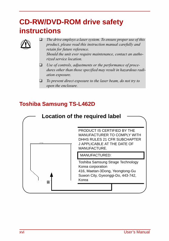
Location of the required label
PRODUCT IS CERTIFIED BY THE MANUFACTURER TO COMPLY WITH DHHS RULES 21 CFR SUBCHAPTER J APPLICABLE AT THE DATE OF MANUFACTURE.
MANUFACTURED:
Toshiba Samsung Strage TechnologyKorea corporation416, Maetan-3Dong, Yeongtong-GuSuwon City, Gyeonggi-Do, 443-742, Korea
xvi User’s Manual
TEAC DW-224E
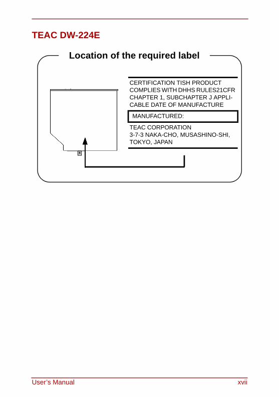
Location of the required label
CERTIFICATION TISH PRODUCT COMPLIES WITH DHHS RULES21CFR CHAPTER 1, SUBCHAPTER J APPLI-CABLE DATE OF MANUFACTURE
MANUFACTURED:
TEAC CORPORATION3-7-3 NAKA-CHO, MUSASHINO-SHI,TOKYO, JAPAN
User’s Manual xvii
HD DVD-ROM and HD DVD-R drive safety instructions
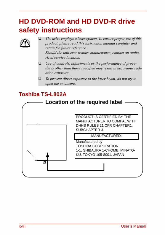
Toshiba TS-L802A
❑ The drive employs a laser system. To ensure proper use of this product, please read this instruction manual carefully and retain for future reference.Should the unit ever require maintenance, contact an autho-rized service location.
❑ Use of controls, adjustments or the performance of proce-dures other than those specified may result in hazardous radi-ation exposure.
❑ To prevent direct exposure to the laser beam, do not try to open the enclosure.
Location of the required label
PRODUCT IS CERTIFIED BY THE MANUFACTURER TO COMPAL WITH DHHS RULES 21 CFR CHAPTER1, SUBCHAPTER J.
MANUFACTURED:
Manufactured byTOSHIBA CORPORATION1-1, SHIBAURA 1-CHOME, MINATO-KU, TOKYO 105-8001, JAPAN
xviii User’s Manual
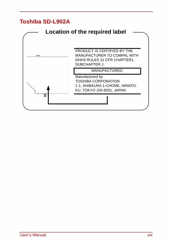
Toshiba SD-L902A
Location of the required label
PRODUCT IS CERTIFIED BY THE MANUFACTURER TO COMPAL WITH DHHS RULES 21 CFR CHAPTER1, SUBCHAPTER J.
MANUFACTURED:
Manufactured byTOSHIBA CORPORATION1-1, SHIBAURA 1-CHOME, MINATO-KU, TOKYO 105-8001, JAPAN
User’s Manual xix
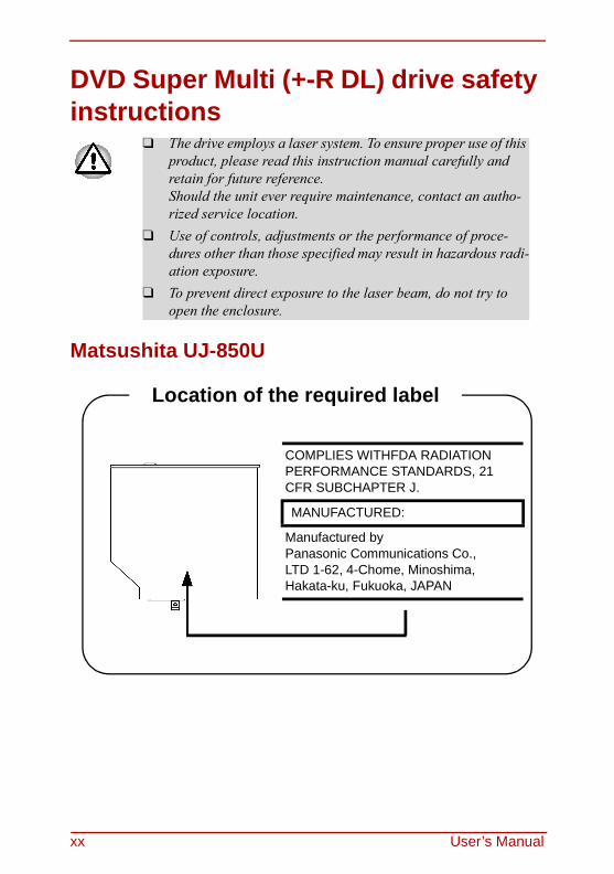
DVD Super Multi (+-R DL) drive safety instructions
Matsushita UJ-850U
❑ The drive employs a laser system. To ensure proper use of this product, please read this instruction manual carefully and retain for future reference.Should the unit ever require maintenance, contact an autho-rized service location.
❑ Use of controls, adjustments or the performance of proce-dures other than those specified may result in hazardous radi-ation exposure.
❑ To prevent direct exposure to the laser beam, do not try to open the enclosure.
Location of the required label
COMPLIES WITHFDA RADIATION PERFORMANCE STANDARDS, 21 CFR SUBCHAPTER J.
MANUFACTURED:
Manufactured byPanasonic Communications Co.,LTD 1-62, 4-Chome, Minoshima,Hakata-ku, Fukuoka, JAPAN
xx User’s Manual
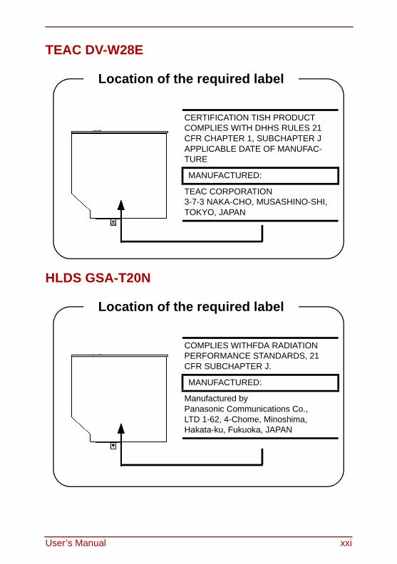
TEAC DV-W28E
HLDS GSA-T20N
Location of the required label
CERTIFICATION TISH PRODUCT COMPLIES WITH DHHS RULES 21 CFR CHAPTER 1, SUBCHAPTER J APPLICABLE DATE OF MANUFAC-TURE
MANUFACTURED:
TEAC CORPORATION3-7-3 NAKA-CHO, MUSASHINO-SHI,TOKYO, JAPAN
Location of the required label
COMPLIES WITHFDA RADIATION PERFORMANCE STANDARDS, 21 CFR SUBCHAPTER J.
MANUFACTURED:
Manufactured byPanasonic Communications Co.,LTD 1-62, 4-Chome, Minoshima,Hakata-ku, Fukuoka, JAPAN
User’s Manual xxi
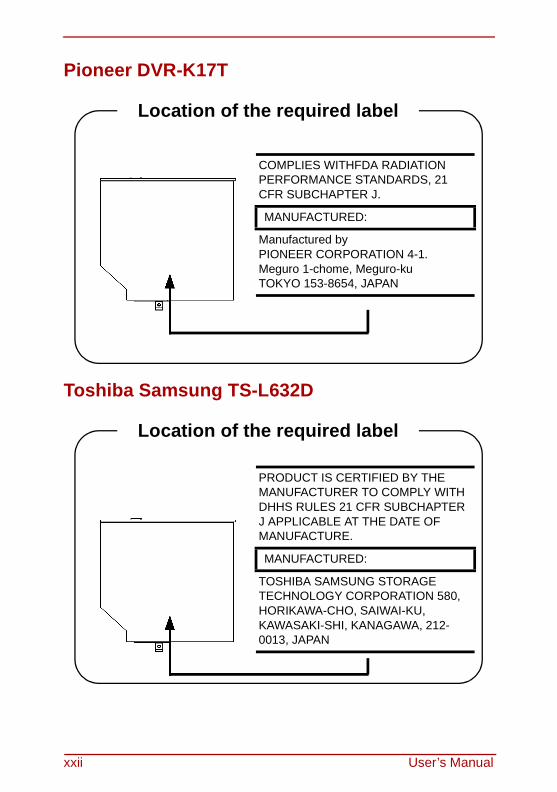
Pioneer DVR-K17T
Toshiba Samsung TS-L632D
Location of the required label
COMPLIES WITHFDA RADIATION PERFORMANCE STANDARDS, 21 CFR SUBCHAPTER J.
MANUFACTURED:
Manufactured byPIONEER CORPORATION 4-1.Meguro 1-chome, Meguro-kuTOKYO 153-8654, JAPAN
Location of the required label
PRODUCT IS CERTIFIED BY THE MANUFACTURER TO COMPLY WITH DHHS RULES 21 CFR SUBCHAPTER J APPLICABLE AT THE DATE OF MANUFACTURE.
MANUFACTURED:
TOSHIBA SAMSUNG STORAGE TECHNOLOGY CORPORATION 580, HORIKAWA-CHO, SAIWAI-KU, KAWASAKI-SHI, KANAGAWA, 212- 0013, JAPAN
xxii User’s Manual
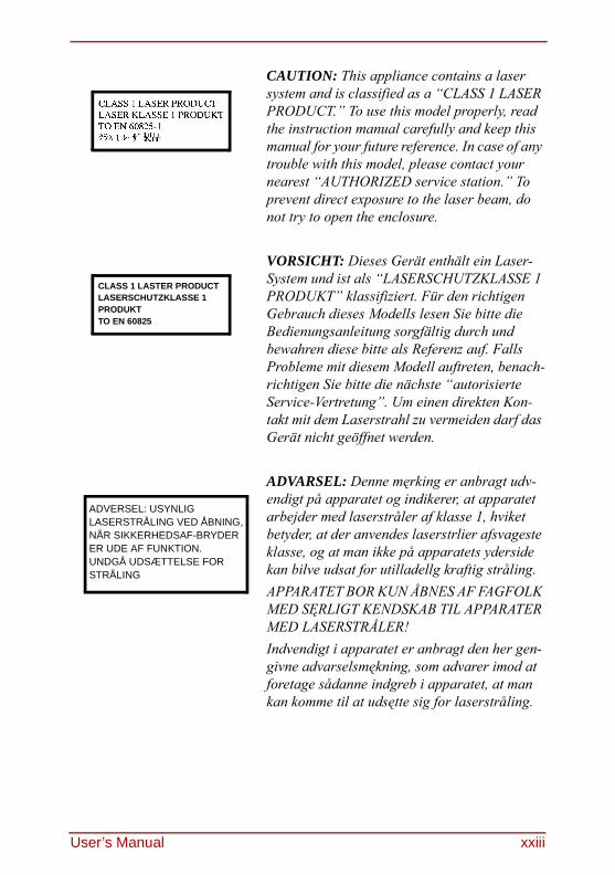
CAUTION: This appliance contains a laser system and is classified as a “CLASS 1 LASER PRODUCT.” To use this model properly, read the instruction manual carefully and keep this manual for your future reference. In case of any trouble with this model, please contact your nearest “AUTHORIZED service station.” To prevent direct exposure to the laser beam, do not try to open the enclosure.
VORSICHT: Dieses Gerät enthält ein Laser-System und ist als “LASERSCHUTZKLASSE 1 PRODUKT” klassifiziert. Für den richtigen Gebrauch dieses Modells lesen Sie bitte die Bedienungsanleitung sorgfältig durch und bewahren diese bitte als Referenz auf. Falls Probleme mit diesem Modell auftreten, benach-richtigen Sie bitte die nächste “autorisierte Service-Vertretung”. Um einen direkten Kon-takt mit dem Laserstrahl zu vermeiden darf das Gerät nicht geöffnet werden.
ADVARSEL: Denne męrking er anbragt udv-endigt på apparatet og indikerer, at apparatet arbejder med laserstråler af klasse 1, hviket betyder, at der anvendes laserstrlier afsvageste klasse, og at man ikke på apparatets yderside kan bilve udsat for utilladellg kraftig stråling.APPARATET BOR KUN ÅBNES AF FAGFOLK MED SĘRLIGT KENDSKAB TIL APPARATER MED LASERSTRÅLER!Indvendigt i apparatet er anbragt den her gen-givne advarselsmękning, som advarer imod at foretage sådanne indgreb i apparatet, at man kan komme til at udsętte sig for laserstråling.
CLASS 1 LASTER PRODUCTLASERSCHUTZKLASSE 1PRODUKTTO EN 60825
ADVERSEL: USYNLIGLASERSTRÅLING VED ÅBNING,NÅR SIKKERHEDSAF-BRYDERER UDE AF FUNKTION.UNDGÅ UDSÆTTELSE FORSTRÅLING
User’s Manual xxiii
OBS! Apparaten innehåller laserkomponent som avger laserstråining överstigande gränsen för laserklass 1.
VAROITUS. Suojakoteloa si saa avata. Laite sisältää laserdiodin, joka lähetää näkymätöntä silmilie vaarallista lasersäteilyä.
CAUTION: USE OF CONTROLS OR ADJUST-MENTS OR PERFORMANCE OF PROCE-DURES OTHER THAN THOSE SPECIFIED IN THE OWNER’S MANUAL MAY RESULT IN HAZARDOUS RADIATION EXPOSURE.
VORSICHT: DIE VERWENDUNG VON ANDEREN STEURUNGEN ODER EINSTEL-LUNGEN ODER DAS DURCHFÜHREN VON ANDEREN VORGÄNGEN ALS IN DER BEDIE-NUNGSANLEITUNG BESCHRIEBEN KÖN-NEN GEFÄHRLICHE STRAHLENEXPOSITIONEN ZUR FOLGE HABEN.
xxiv User’s Manual
Table of ContentsPrefaceManual contents...........................................................xxxiiiConventions .................................................................xxxiv
Abbreviations ..............................................................xxxivIcons ...........................................................................xxxivKeys............................................................................xxxivKey operation...............................................................xxxvDisplay .........................................................................xxxvMessages ....................................................................xxxvTerminology .................................................................xxxv
General PrecautionsCreating a computer-friendly environment ..............xxxviiStress injury ................................................................xxxviiHeat injury ..................................................................xxxviiiPressure or impact damage......................................xxxviiiExpress Card overheating ........................................xxxviiiMobile phone..............................................................xxxviiiInstruction Manual for safety and Comfort .............xxxviiiChapter 1 IntroductionEquipment checklist ........................................................1-1
Hardware .......................................................................1-1Software.........................................................................1-2
Features ............................................................................1-3Processor.......................................................................1-3Memory..........................................................................1-3Disks ..............................................................................1-4
Special Features ............................................................1-11TOSHIBA Value Added Package ..................................1-13Utilities and Application ................................................1-14
User’s Manual xxv
Options ...........................................................................1-17Chapter 2 The Grand TourFront with the display closed .........................................2-1Left side ............................................................................2-3Right side..........................................................................2-6Back side ..........................................................................2-7Underside .........................................................................2-8Front with the display open ............................................2-9
AV Button.....................................................................2-11System indicators ........................................................2-12
Optical disc drive ...........................................................2-14About the HD DVD.......................................................2-14Region codes for DVD drives and media.....................2-15Writable discs ..............................................................2-16CD-RW/DVD-ROM drive .............................................2-18DVD Super Multi (+-R DL) drive ..................................2-19HD DVD ROM drive.....................................................2-20HD DVD-R drive ..........................................................2-21
Remote Controller..........................................................2-22Using the Remote Controller .......................................2-26
Installing/Removing batteries.......................................2-27Installing the batteries..................................................2-28Replacing the batteries ................................................2-30
AC adaptor......................................................................2-31Chapter 3 Getting StartedConnecting the AC adaptor ............................................3-2Opening the display.........................................................3-3Turning on the power ......................................................3-3Starting up for the first time............................................3-4Turning off the power ......................................................3-4
Shut Down mode (Boot mode) ......................................3-4Hibernation mode ..........................................................3-5Starting Hibernation .......................................................3-6Automatic Hibernation ...................................................3-6
xxvi User’s Manual
Sleep mode....................................................................3-7Restarting the computer .................................................3-8System Recovery Options ..............................................3-9
System Recovery Options .............................................3-9Create Optical Recovery Discs.....................................3-10
For HDD Recovery model............................................3-10Restoring the preinstalled software from the Recovery HDD .................................................................................3-10Restoring the preinstalled software from your creating Recovery Media..............................................................3-11Chapter 4 Operating BasicsUsing the Touch Pad/Dual Mode Pad ............................4-1Dual Mode Pad Button function .....................................4-2Using the Fingerprint Sensor .........................................4-3
Points to note about the Fingerprint Sensor ..................4-4Points to note about the Fingerprint Utility.....................4-6Set Up Procedure ..........................................................4-6Windows Logon via Fingerprint Authentication..............4-8Fingerprint System Boot Authentication ........................4-9Fingerprint Single Sign-On Feature .............................4-10How to Swipe the Finger..............................................4-11
Using optical disc drives...............................................4-12Loading discs...............................................................4-13Removing discs ...........................................................4-15AV Button function .......................................................4-16
Using TOSHIBA HD DVD PLAYER to enjoy HD DVDs 4-17HD DVD Playback Restrictions....................................4-17Notes on use................................................................4-17Notes on playing HD DVD Video discs........................4-18TOSHIBA HD DVD PLAYER.......................................4-20
Using TOSHIBA HD DVD PLAYER ...............................4-20Starting TOSHIBA HD DVD PLAYER..........................4-20Operating TOSHIBA HD DVD PLAYER ......................4-21Open TOSHIBA HD DVD PLAYER HELP...................4-23TOSHIBA HD DVD PLAYER Control window .............4-23
User’s Manual xxvii
Using the Computer in place of an HD DVD Player ....4-26Before Connecting .......................................................4-26Connecting to the Computer........................................4-27Switching between Computer and Television Display .4-27
Display Compatibility ....................................................4-28Writing CDs on CD-RW/DVD-ROM drive......................4-29
Important message (CD-RW/DVD-ROM drive) ...........4-29Before writing or rewriting ............................................4-29When writing or rewriting .............................................4-30Disclaimer (CD-RW/DVD-ROM drive) .........................4-31
Writing CD/DVDs on DVD Super Multi (+-R DL) drive.4-31Important message (DVD Super Multi (+-R DL) drive) 4-31Before writing or rewriting ............................................4-31When writing or rewriting .............................................4-34Disclaimer (DVD Super Multi (+-R DL) drive) ..............4-35
Writing CD/DVD/HD DVDs on HD DVD-R drives..........4-35When writing or rewriting .............................................4-39TOSHIBA Disc Creator ................................................4-40Data Verification ..........................................................4-42Video............................................................................4-42When using Ulead DVD MovieFactory® for TOSHIBA:...4-42
Media care ......................................................................4-46CD/DVD/HD DVD ........................................................4-46Using the software .......................................................4-48
Using the microphone ...................................................4-49Modem ............................................................................4-50
Region selection ..........................................................4-50Properties menu ..........................................................4-51
Wireless communications.............................................4-53Wireless LAN...............................................................4-53
LAN..................................................................................4-56Connecting LAN cable .................................................4-56Disconnecting LAN cable.............................................4-57
Cleaning the computer ..................................................4-58
xxviii User’s Manual
Moving the computer.....................................................4-58Heat dispersal ................................................................4-59Chapter 5 The KeyboardTypewriter keys................................................................5-1F1 ... F12 function keys ...................................................5-2Soft keys: FN key combinations.....................................5-2
Emulating keys on enhanced keyboard.........................5-2Hot keys.........................................................................5-3FN Sticky key.................................................................5-6
Windows special keys .....................................................5-7Keypad overlay ................................................................5-7
Turning on the overlays .................................................5-7Arrow mode ...................................................................5-7Numeric mode ...............................................................5-8Temporarily using normal keyboard (overlay on) ..........5-8Temporarily using overlay (overlay off)..........................5-9Temporarily changing modes ........................................5-9
Generating ASCII characters ..........................................5-9Chapter 6 Power and Power-Up ModesPower conditions .............................................................6-1Power indicators ..............................................................6-3
Battery indicator.............................................................6-3DC IN indicator ..............................................................6-3Power indicator ..............................................................6-4
Battery types ....................................................................6-4Battery ...........................................................................6-4Real time clock battery ..................................................6-5
Care and use of the battery pack ...................................6-6Safety precautions .........................................................6-6Charging the batteries ...................................................6-9Monitoring battery capacity..........................................6-11Maximizing battery operating time ...............................6-12Retaining data with power off ......................................6-13Extending battery life ...................................................6-13
User’s Manual xxix
Replacing the battery pack ...........................................6-14Removing the battery pack ..........................................6-14Installing the battery pack ............................................6-16
Starting the computer by password.............................6-16Power-up modes..........................................................6-17Windows utilities ..........................................................6-17Hot keys.......................................................................6-17Panel power on/off.......................................................6-18System Auto Off...........................................................6-18
Chapter 7 HW Setup and PasswordsHW Setup ..........................................................................7-1
Accessing HW Setup .....................................................7-1HW Setup window .........................................................7-1
Chapter 8 Optional DevicesCards/memory ...............................................................8-1Power devices ...............................................................8-1Peripheral devices .........................................................8-1Other..............................................................................8-1
Express Card....................................................................8-2Installing an Express Card.............................................8-2Removing an Express Card...........................................8-3
Multiple Digital Media Card Slot .....................................8-4Installing a SD/SDHC/MS/MS Pro/MMC/xD card ..........8-4Removing a SD/SDHC/MS/MS Pro/MMC/xD card ........8-6
Memory expansion ..........................................................8-7Installing memory module..............................................8-7Removing memory module............................................8-9
Additional battery pack (6 Cell and 9 Cell) ..................8-10Additional AC adaptor ...................................................8-10USB FDD Kit ...................................................................8-10External monitor ............................................................8-11Television .......................................................................8-12HDMI................................................................................8-13i.LINK (IEEE1394) ...........................................................8-14
xxx User’s Manual
Precautions..................................................................8-14Connecting...................................................................8-15Disconnecting ..............................................................8-16Security lock ................................................................8-16
Chapter 9 TroubleshootingProblem solving process ................................................9-1
Preliminary checklist ......................................................9-1Analyzing the problem ...................................................9-2
Hardware and system checklist .....................................9-3System start-up..............................................................9-3Self test..........................................................................9-4Power.............................................................................9-4Password .......................................................................9-7Keyboard .......................................................................9-7LCD panel......................................................................9-8Hard disk drive...............................................................9-8CD-RW/DVD-ROM drive ...............................................9-9HD DVD ROM drive.....................................................9-10HD DVD-R drive ..........................................................9-11DVD Super Multi (+-R DL) drive ..................................9-12Diskette drive ..............................................................9-14Infrared port .................................................................9-14Pointing device ............................................................9-14Touch Pad/Dual Mode Pad..........................................9-15USB mouse..................................................................9-17Fingerprint Sensor .......................................................9-18Express Card ...............................................................9-19SD/SDHC/MS/MS Pro/MMC/xD card ..........................9-19Monitor.........................................................................9-20Sound system..............................................................9-21TV output signal...........................................................9-21USB .............................................................................9-22Modem.........................................................................9-22Sleep/Hibernation ........................................................9-24LAN..............................................................................9-24
User’s Manual xxxi
Wireless LAN...............................................................9-24Bluetooth......................................................................9-25i.LINK (IEEE1394) .......................................................9-25Recovery Discs...........................................................9-26
TOSHIBA support ..........................................................9-27Before you call .............................................................9-27
Chapter 10 DisclaimersCPU .................................................................................10-1Memory (Main System)..................................................10-2Battery Life .....................................................................10-2HDD Drive Capacity .......................................................10-3LCD..................................................................................10-3Graphics Processor Unit ("GPU") ................................10-3Wireless LAN..................................................................10-4Non-applicable Icons.....................................................10-4Copy Protection .............................................................10-4Images.............................................................................10-4LCD Brightness and Eye Strain....................................10-4AppendixesAppendix ASpecifications.................................................................. A-1Appendix BDisplay Controller and Modes ....................................... B-1Appendix CV.90/V.92 .......................................................................... C-1Appendix DWireless LAN................................................................... D-1Appendix EAC Power Cord and Connectors ................................... E-1GlossaryAbbreviations ..................................................... Glossary-1Index
xxxii User’s Manual
PrefaceCongratulations on your purchase of the TOSHIBA Satellite A210/Satellite Pro A210 computer. This powerful, lightweight notebook computer is designed to provide years of reliable, high-performance computing.This manual tells how to set up and begin using your Satellite A210/Satellite Pro A210 computer. It also provides detailed information on configuring your com-puter, basic operations and care, using optional devices and troubleshooting. If you are a new user of computers or if you’re new to portable computing, first read over the Introduction and The Grand Tour chapters to familiarize yourself with the computer’s features, components and accessory devices. Then read Get-ting Started for step-by-step instructions on setting up your computer.If you are an experienced computer user, please continue reading the preface to learn how this manual is organized, then become acquainted with this manual by browsing through its pages. Be sure to look over the Special Features section of the Introduction, to learn about features that are uncommon or unique to the computers and carefully read HW Setup and Passwords. If you are going to install Express Cards or connect external devices such as a printer, be sure to read Chapter 8, Optional Devices.
Manual contentsThis manual is composed of ten chapters, five appendixes, a glossary, and an index.Chapter 1, Introduction, is an overview of the computer’s features, capabilities, and options.Chapter 2, The Grand Tour, identifies the components of the computer and briefly explains how they function.Chapter 3, Getting Started, provides a quick overview of how to begin operating your computer. Chapter 4, Operating Basics, includes tips on care of the computer and on using the Touch Pad/Dual Mode Pad, optical disc drive, external diskette drive, Wire-less LAN, LANs, Audio/Video controls, and internal modem.Chapter 5, The Keyboard, describes special keyboard functions including the keypad overlay and hot keys.
User’s Manual xxxiii
Preface
Chapter 6, Power and Power-Up Modes, gives details on the computer’s power resources and battery save modes.Chapter 7, HW Setup and Passwords, explains how to configure the computer using the HW Setup program. It also tells how to set a password.Chapter 8, Optional Devices, describes the optional hardware available.Chapter 9, Troubleshooting, provides helpful information on how to perform some diagnostic tests, and suggests courses of action if the computer doesn’t seem to be working properly.Chapter 10, Disclaimers, states the Disclaimer(s) information applicable to TOSHIBA computer.The Appendixes provide technical information about your computer.The Glossary defines general computer terminology and includes a list of acro-nyms used in the text.The Index quickly directs you to the information contained in this manual.
ConventionsThis manual uses the following formats to describe, identify, and highlight terms and operating procedures.
AbbreviationsOn first appearance, and whenever necessary for clarity, abbreviations are enclosed in parentheses following their definition. For example: Read Only Memory (ROM). Acronyms are also defined in the Glossary.
IconsIcons identify ports, dials, and other parts of your computer. The indicator panel also uses icons to identify the components it is providing information on.
KeysThe keyboard keys are used in the text to describe many computer operations. A distinctive typeface identifies the key top symbols as they appear on the key-board. For example, ENTER identifies the Enter key.
xxxiv User’s Manual
Preface
Key operationSome operations require you to simultaneously use two or more keys. We iden-tify such operations by the key top symbols separated by a plus sign (+). For example, CTRL + C means you must hold down CTRL and at the same time press C. If three keys are used, hold down the first two and at the same time press the third.
ABC When procedures require an action such as clicking an icon or entering text, the icon’s name or the text you are to type in is represented in the type face you see to the left.
DisplayABC Names of Windows or icons or text generated by the computer that
appears on its display screen is presented in the type face you see to the left.
MessagesMessages are used in this manual to bring important information to your atten-tion. Each type of message is identified as shown below.
TerminologyThis term is defined in this document as follows:
Start The word “Start” refers to the “ ” button in Microsoft® Windows Vista™.
Pay attention! A caution informs you that improper use of equipment or failure to follow instructions may cause data loss or damage your equipment.
Please read. A note is a hint or advice that helps you make best use of your equipment.
User’s Manual xxxv

Preface
xxxvi User’s Manual
General PrecautionsTOSHIBA computers are designed to optimize safety, minimize strain and with-stand the rigors of portability. However, certain precautions should be observed to further reduce the risk of personal injury or damage to the computer.Be certain to read the general precautions below and to note the cautions included in the text of the manual.
Creating a computer-friendly environmentPlace the computer on a flat surface that is large enough for the computer and any other items you are using, such as a printer.Leave enough space around the computer and other equipment to provide ade-quate ventilation. Otherwise, they may overheat.To keep your computer in prime operating condition, protect your work are from:❑ Dust, moisture, and direct sunlight❑ Equipment that generates a strong electromagnetic field, such as stereo
speakers (other than speakers that are connected to the computer) or speak-erphones.
❑ Rapid changes in temperature or humidity and some sources of temperature change such as air conditioner vents or heaters.
❑ Extreme heat, cold, or humidity.❑ Liquids and corrosive chemicals.
Stress injuryCarefully read the Instruction Manual for Safety & Comfort. It contains informa-tion on prevention of stress injuries to your hands and wrists that can be caused by extensive keyboard use.
User’s Manual xxxvii
General Precautions
Heat injury❑ Avoid prolonged physical contact with the computer. If the computer is used
for long periods, its surface can become very warm. While the temperature will not feel hot to the touch, if you maintain physical contact with the com-puter for a long time, for example if you rest the computer on your lap or if you keep your hands on the palm rest, your skin might suffer low-heat injury.
❑ If the computer has been used for a long time, avoid direct contact with the metal plate supporting the various interface ports as this can become hot.
❑ The surface of the AC adaptor can become hot when in use but this condi-tion does not indicate a malfunction. If you need to transport the AC adaptor, you should disconnect it and let it cool before moving it.
❑ Do not lay the AC adaptor on a material that is sensitive to heat as the mate-rial could become damaged.
Pressure or impact damageDo not apply heavy pressure to the computer or subject it to any form of strong impact as this can damage the computer’s components or otherwise cause it to malfunctions.
Express Card overheatingSome Express Cards can become hot during prolonged use which may result in errors or instability in the operation of the device in question. In addition, you should also be careful when you remove an Express Card that has been used for a long time.
Mobile phonePlease be aware that use of mobile phones can interface with the audio system. The operation of the computer will not be impared in any way, but it is recom-mended that a minimum distance of 30cm is maintained between the computer and a mobile phone that is in use.
Instruction Manual for safety and ComfortAll important information on the safe and proper use of this computer is described in the enclosed Instruction Manual for Safety Comfort. Be sure to read it before using the compute
xxxviii User’s Manual
User’s Manual 1-1
INTRODUCTIO
N
Chapter 1
IntroductionThis chapter provides an equipment checklist, and it identifies the computer’s features, options and accessories.
Equipment checklistCarefully unpack your computer. Save the box and packing materials for future use.
HardwareCheck to make sure you have all the following items:❑ Satellite A210/Satellite Pro A210 Portable Personal Computer❑ Universal AC adaptor and power cord❑ Modular cable (Provided with some models)
Some of the features described in this manual may not function properly if you use an operating system that was not pre- installed by TOSHIBA.
IntroductionIN
TRO
DUCT
ION
Software
Windows Vista™◆ The following software is preinstalled:
• Microsoft® Windows Vista™• Modem Driver (Can be used only for Modem models)• Display Drivers for Windows• Wireless LAN driver (Can be used only for Wireless LAN models)• Sound Driver for Windows• TOSHIBA DVD Player (Is pre-installed with CD-RW/DVD-ROM drive
model or DVD Super Multi drive model)• TOSHIBA HD DVD Player (Is pre-installed with HD DVD-ROM drive
model or HD DVD-R drive model)• LAN Drivers• Bluetooth Driver (Can be used only for Bluetooth models)• Pointing Device Driver• TOSHIBA Power Saver• TOSHIBA User’s Manual• TOSHIBA Assist• TOSHIBA ConfigFree• TOSHIBA PC Diagnostic Tool• TOSHIBA Zooming Utility• TOSHIBA CD/DVD Drive Acoustic Silencer• TOSHIBA Disc Creator
• Ulead DVD MovieFacotry® for TOSHIBA• Fingerprint utility (Can be used only for Fingerprint utility models)
• TOSHIBA SD Memory UtilitiesSD Memory Card Format Utility and other SD functions are packaged into TOSHIBA SD Memory Utilities. When uninstalling the SD utilities, click Start → Control Panel → Uninstall a program, and select TOSHIBA SD Memory Utilities.
1-2 User’s Manual
IntroductionINTRO
DUCTION
◆ Documentation:• User Information Guide
• Microsoft® Windows Vista™ manual package (provided with some mod-els)
• Instruction Manual for Safety & Comfort• End User License Agreement
FeaturesThis computer incorporates the following features and benefits:
Processor
Memory
Built-in Please visit your region’s website for the configuration details of the model that you have purchased.
Slots PC2-4200 or PC2-5300 512 MB, 1024 MB or 2048 MB memory modules can be installed in the two memory slots.Maximum system memory size is depending on the model you purchased.
Video RAM Integrated Video Memory in graphic chip by ATI Radeon™ X1200, up to 256MB shared with main memory.(for more than 1GB main memory)
User’s Manual 1-3
IntroductionIN
TRO
DUCT
ION
DisksHard disk drive The computer has an integrated, 2 1/2" hard disk drive
(HDD) for nonvolatile storage of data and software. It comes in the following sizes.60 GB80 GB100 GB120 GB160 GB200 GB250 GB300 GBDisclaimer (Hard disk drive capacity)For more information on the Disclaimer regarding Hard disk drive capacity, please refer to the Disclaimer sec-tion in chapter 10.
CD-RW/DVD-ROM drive
Some models are equipped with a full-size, CD-RW/DVD-ROM drive module that lets you run CD/DVDs without using an adaptor. It reads DVD-ROMs at maxi-mum 8 speed and CD-ROMs at maximum 24 speed. It writes CD-R at up to 24 speed and CD-RW at up to 24 speed. See Chapter 4, Operating Basics, for details. For reading, this drive supports the same formats as the DVD-ROM drive.
1-4 User’s Manual
IntroductionINTRO
DUCTION
DVD Super Multi(+-R DL) drive
Some models are equipped with a full-size DVD Super Multi (+- R DL) drive module that lets you record data to rewritable CD/DVDs as well as run either 12 cm (4.72") or 8 cm (3.15") CD/DVDs without using an adaptor. It reads DVD-ROMs at maximum 8 speed and CD-ROMs at maximum 24 speed. It writes CD-R at up to 24 speed, CD-RW at up to 16 speed, DVD-R at up to 8 speed and DVD-RW at maximum 6 speed and DVD-RAM at maximum 5 speed. DVD+R at up to 8 speed and DVD+RW at up to 8 speed. DVD+R DL at up to 4 speed and DVD-R DL at up to 4 speed. This drive sup-ports the same formats as the DVD-ROM drive.• DVD-ROM • DVD-Video• DVD-R • DVD-RW• DVD+R • DVD+RW• DVD-RAM• DVD+R DL• DVD-R DL• CD-DA • CD-Text• Photo CD (single/multi-session)• CD-ROM Mode 1, Mode 2• CD-ROMXA Mode 2 (Form1, Form2)• Enhanced CD (CD-EXTRA)• CD-G (Audio CD only)• Addressing Method 2
User’s Manual 1-5
IntroductionIN
TRO
DUCT
ION
HD DVD ROMdrive
Some models are equipped with a full-size HD DVD-ROM drive module that lets you run CD's or DVD's without using an adaptor. The drive reads DVD-ROM's at a maximum 8x speed and CD-ROM's at a maximum 24x speed, and HD DVD's at a maximum 1x speed and writes CD-R's at up to 16x speed, CD-RW's at up to 10x speed, DVD-R's and DVD+R's at up to 4x speed, DVD-RW's and DVD+RW's at up to 4x speed, DVD-R (Dual layer) at up to 2x speed, DVD+R (Double Layer) at up to 2.4x speed and DVD-RAM at up to 3x speed, and supports the following formats:
• CD-R • CD-RW• DVD-ROM • DVD-Video• CD-DA • CD-Text• Photo CD. (single/multi-session)• CD-ROM Mode 1, Mode 2• CD-ROM XA Mode 2 (Form1, Form2)• Enhanced CD (CD-EXTRA)• Addressing Method 2• DVD-R• DVD-R (Dual Layer)• DVD-RW• DVD+R• DVD+R (Double Layer)• DVD+RW• DVD-RAM
• HD DVD-ROM
1-6 User’s Manual
IntroductionINTRO
DUCTION
Keyboard
HD DVD-R drive Some models are equipped with a full-size HD DVD-R drive module that lets you run CD's or DVD's without using an adaptor. The drive reads DVD-ROM's at a maximum 8x speed and CD-ROM's at a maximum 24x speed, and HD DVD's at a maximum 1x speed and writes CD-R's at up to 16x speed, CD-RW's at up to 4x speed, DVD-R's and DVD+R's at up to 4x speed, DVD-RW's and DVD+RW's at up to 4x speed, DVD-R (Dual layer) at up to 2x speed, DVD+R (Double Layer) at up to 2.4x speed and DVD-RAM at up to 3x speed, HD DVD-R at up to 1x speed, and supports the following formats:
• CD-R • CD-RW• DVD-ROM • DVD-Video• CD-DA • CD-Text• CD-DA • CD-Text• Photo CD. (single/multi-session)• CD-ROM Mode 1, Mode 2• CD-ROM Mode 1, Mode 2• CD-ROM XA Mode 2 (Form1, Form2)• Enhanced CD (CD-EXTRA)• Addressing Method 2• DVD-R• DVD-R (Dual Layer)• DVD-RW• DVD+R• DVD+R (Double Layer)• DVD+RW• DVD-RAM• HD DVD-ROM
• HD DVD-R
Built-in 85 keys or 86 keys, compatible with IBM® enhanced keyboard, embedded numeric overlay, dedicated cursor control, and keys. See Chapter 5, The Key-board, for details.
User’s Manual 1-7
IntroductionIN
TRO
DUCT
ION
Pointing Device
Power
Ports
Built-in A Touch Pad/Dual Mode Pad and control buttons in the palm rest enable control of the on-screen pointer.
Battery pack The computer is powered by one rechargeable lithium-ion battery pack.
RTC battery The internal RTC battery backs up the Real Time Clock (RTC) and calendar.
AC adaptor The universal AC adaptor provides power to the system and recharges the batteries when they are low. It comes with a detachable power cord. Because it is universal, it can receive a range of AC voltage between 100 and 240 volts.
Headphone Enables connection of a stereo headphone.Microphone Enables connection of a monaural microphone.
External monitor 15-pin, analog VGA port supports VESA DDC2B com-patible functions.
Universal Serial Bus(USB2.0)
Four Universal Serial Bus (USB) enables chain connec-tion of a number of USB-equipped devices to one port on your computer.
i.LINK™(IEEE 1394)
This port enables high-speed data transfer directly from external devices such as digital video camera.(Provided with some models.)
Video Out Jack This S-Video out port lets you transfer NTSC or PAL data to external devices.
HDMI This HDMI jack lets you connect external devices. (Pro-vided with some models)
1-8 User’s Manual
IntroductionINTRO
DUCTION
Slots
Multimedia
Communications
Multiple DigitalMedia Card
This slot lets you easily transfer data from devices, such as digital cameras and Personal Digital Assistants, that use flash memory (SD/SDHC/MS/MS Pro/MMC/xD memory cards). (Provided with some models)
Express Card Express Card slot allows you to install a Express Card™/34 or Express Card™/54 to expand functional-ity.Refer to Chapter 8, Optional Devices, for details.
Web Camera Record/Send still or video images with this integrated Web Camera.
Sound System Windows Sound System compatible sound system pro-vides internal speaker as well as jacks for an external microphone and headphone. It also has a volume control dial.
S-Video Out Port This S-Video out port lets you transfer NTSC or PAL data to external devices. See Chapter 8, Television, for details.
LAN The computer is equipped with a LAN card that sup-ports Ethernet LAN (10 Mbit/s, 10BASE-T) or Fast Ethernet LAN (100 Mbit/s, 100BASE-TX). It is prein-stalled as a standard device in some markets.(Depending on model you purchased)
Wireless LAN Some computers in this series are equipped with a Wire-less LAN mini card that is compatible with other LAN systems based on Direct Sequence Spread Spectrum/Orthogonal Frequency Division Multiplexing radio technology that complies with the IEEE 802.11 Stan-dard (Revision A, B, G and Draft N).Roaming over multiple channels.
User’s Manual 1-9
IntroductionIN
TRO
DUCT
ION
Security
Software
Modem Some computers in this series are equipped with an internal modem. The internal modem provides capabil-ity for data and fax communication. It supports V.90 (V.92). Refer to V.90 section in Appendix C. The speed of date transfer and fax depends on analog telephone line conditions. It has a modem jack for connecting to a telephone line. It is preinstalled as a standard device in some markets. Both of V.90 and V.92 are supported only in USA, Canada and Australia. Only V.90 is available in other regions.
Bluetooth® Some computers in this series are equipped with Blue-tooth functions. Bluetooth® wireless technology elimi-nates the need for cables between electronic devices such as computers and printers. Bluetooth® provides fast, reliable, and secure wireless communication in a small space.
Wireless Communi-cation Switch
This switch turns the Wireless LAN and Bluetooth func-tion on and off. (Provided with some models)
Security lock slot Connects an optional security lock to anchor the com-puter to a desk or other large object.
Operating System Windows Vista™ is available. Refer to the preinstalled software section at the front of this chapter.
TOSHIBA Utilities A number of utilities and drivers are preinstalled to make your computer more convenient to use. Refer to the Utilities section in this chapter.
Plug and Play When you connect an external device to the computer or when you install a component, Plug and Play capability enables the system to recognize the connection and make the necessary configurations automatically.
1-10 User’s Manual
IntroductionINTRO
DUCTION
Special FeaturesThe following features are either unique to TOSHIBA computers or are advanced features, which make the computer more convenient to use.
Hot keys Key combinations let you quickly modify the system configuration directly from the keyboard without run-ning a system configuration program.
Display automaticpower off
This feature automatically cuts off power to the internal display when there is no keyboard input for a time spec-ified. Power is restored when any key is pressed. You can specify the time in the Monitor power off item of the Basic Setup tab in TOSHIBA Power Saver.
HDD automaticpower off
This feature automatically cuts off power to the hard disk drive when it is not accessed for a time specified. Power is restored when the hard disk is accessed. You can specify the time in the HDD Power off item of the Basic Setup tab in TOSHIBA Power Saver.
System automaticSleep/Hibernation
This feature automatically shuts down the system in sleep mode or Hibernation mode when there is no input or hardware access for a time specified. You can specify the time and select either System Sleep or System hiber-nation in the System sleep and System item of the Basic Setup tab in TOSHIBA Power Saver.
Keypad overlay A ten-key pad is integrated into the keyboard. Refer to the Keypad overlay section in Chapter 5, The Keyboard, for instructions on using the keypad overlay.
Power on password Two levels of password security, supervisor and user, are available to prevent unauthorized access to your computer.
Instant security A hot key function blanks the screen and disables the computer providing data security.
Intelligent powersupply
A microprocessor in the computer’s intelligent power supply detects the battery’s charge and calculates the remaining battery capacity. It also protects electronic components from abnormal conditions, such as voltage overload from an AC adaptor. You can monitor remain-ing battery capacity. Use the Battery remaining item in TOSHIBA Power Saver.
User’s Manual 1-11
IntroductionIN
TRO
DUCT
ION
Battery save mode This feature lets you save battery power. You can spec-ify the Power Save Mode in the Profile item in TOSHIBA Power Saver.
Panel power on/off This feature turns power to the computer off when the display panel is closed and turns it back on when the panel is opened. You can specify the setting in the When I close the lid item of the Setup Action tab in TOSHIBA Power Saver.
Low battery auto-matic hibernation
When battery power is exhausted to the point that com-puter operation cannot be continued, the system auto-matically enters Hibernation and shuts down. You can specify the setting in the Setup Action tab in TOSHIBA Power Saver.
Heat dispersal To protect from overheating, the CPU has an internal temperature sensor. If the computer’s internal tempera-ture rises to a certain level, the cooling fan is turned on or the processing speed is lowered. Use the Cooling Method item of the Basic Setup tab in TOSHIBA Power Saver.MaximumPerformance
Turns on fan first, then if necessary lowers CPU processing speed.
Batteryoptimized
Lowers the CPU processing speed first, then if necessary turns on the fan.
Hibernation This feature lets you turn off the power without exiting from your software. The contents of main memory are saved to the hard disk, when you turn on the power again, you can continue working right where you left off. Refer to the Turning off the power section in Chap-ter 3, Getting Started, for details.
Sleep If you have to interrupt your work, you can turn off the power without exiting from your software. Data is maintained in the computer’s main memory. When you turn on the power again, you can continue working right where you left off.
1-12 User’s Manual
IntroductionINTRO
DUCTION
TOSHIBA Value Added PackageThis section describes the TOSHIBA Component features pre-installed on the computer.
TOSHIBA Power Saver
TOSHIBA Power Saver provides you with the feature of more various power supply managements.
TOSHIBA Button Support
This utility controls the following computer button functions.- Internet button- CD/DVD buttonThe starting application from the button can be changed.
TOSHIBA Zooming Utility
This utility allows you to enlarge or reduce the icon size on the Windows Desktop, or the zoom factor associated with specific supported applications.
TOHSIBA PCDiagnostic Tool
The TOSHIBA PC Diagnostic Tool will display basic system configuration information and allow the func-tionality of some of the computer’s built-in hardware devices to be tested.
TOSHIBA Flash Cards
This utility supports the following functions.❑ Hot Key function.❑ TOSHIBA utility launcher function.
When you start or resume your computer, the TOSHIBA Flash Cards may take a moment to become available and may display several times before completely activating. The hot key functions will be available once the TOSHIBA Flash Cards are completely active.
If your system is busy and you see a “Not Responding” message, allow TOSHIBA Flash Cards to completely activate before you continue to use the utility and hot keys.
TOSHIBAComponents
common Driver
TOSHIBA Components Common Driver contains the module required for the utility which TOSHIBA offers.
User’s Manual 1-13
IntroductionIN
TRO
DUCT
ION
Utilities and ApplicationThis section describes pre-installed utilities and tells how to start them. For details on operation, refer to each utility’s online manual, help files or readme.txt files.
TOSHIBAAccessibility
The TOSHIBA Accessibility utility provides support to movement impaired users when they need to use the TOSHIBA Hot-key functions. In use, the utility allows you to make the FN key "sticky", that is you can press it once, release it, and then press one of the "F" keys in order to access its specific function. When set, the FN key will remain active until another key is pressed.
TOSHIBA Assist TOSHIBA Assist is a graphical user interface that pro-vides easy access to help and services.
HW Setup To start the utility, click the Windows Start button, point to All Programs, click TOSHIBA, click Utilities, and select HWSetup icon.
TOSHIBA DVDVideo Player
This software is provided for playback of DVD Video.(This software is pre-installed with CD-RW/DVD-ROM drive or DVD Super Multi drive model.)
TOSHIBA HDDVD Video Player
This software is provided for playback of HD DVD Video and DVD Video.
(This software is pre-installed with HD DVDROM drive or HD DVD-R drive model.)
TOSHIBA Disc Creator
You can create CD/DVDs in several formats including audio CDs that can be played on a standard stereo CD player and data CD/DVDs to store the files and folder-son your hard disk drive. This software can be used on a model with CD-RW/DVD-ROM drive, DVD-R/-RW drive, DVD+-R/+-RW drive and DVD Super Multi drive.You can boot TOSHIBA Disc Creator from the menu bar as follows. Start → All Programs → TOSHIBA → CD&DVD Applications → Disc Creator
1-14 User’s Manual
IntroductionINTRO
DUCTION
TOSHIBA DVD-RAM Utility
TOSHIBA DVD-RAM Utility has the function of Phys-ical Format and Write-Protect to DVD-RAM.This utility is contained the setup module of TOSHIBA Disc Creator.You can boot TOSHIBA DVD-RAM Utility from the menu bar as follows.Start → All Programs → TOSHIBA → CD&DVD Applications → DVD-RAM Utility
Ulead DVDMovie®Factory for
TOSHIBA
You can edit digital video and make a DVD-Video and support Labelflash function.
TOSHIBA ConfigFree
ConfigFree is a suite of utilities to allow easy control of communication device and network connections. Con-figFree also allows you to find communication prob-lems and create profiles for easy switching between location and communication networks.You can boot ConfigFree from the menu bar as follows.Start → All Programs → TOSHIBA → Network-ing → ConfigFree
Dual Mode Pad The Dual Mode TouchPad is a TouchPad that provides normal Synaptics features in its default mode and switches to a DualMode interface when the upper right corner of the TouchPad is tapped. Tapping the same cor-ner again will revert to normal pointing mode.
The volume control on the right side of the Touch Pad and print button may not function with some applications.
BluetoothTOSHIBA Stack
This software enables communication between remote Bluetooth devices.
Bluetooth cannot be used in models that do not have a Bluetooth module installed.
User’s Manual 1-15
IntroductionIN
TRO
DUCT
ION
Fingerprint Utility This product has a fingerprint utility installed for the purpose of enrolling and recognizing fingerprints. By enrolling the ID and password to the fingerprint authen-tication device, it is no longer necessary to input the password from the keyboard. Just by swiping the finger against the fingerprint sensor, the following functions will be enabled:❑ Logon to Windows and access a security-enabled
homepage through IE (Internet Explorer).❑ Files and folders can be encrypted/decrypted and
third party access to them prevented.❑ Disable the password-protected screen-saver when
returning from power-saving (sleep) mode.❑ Power-on Security and Single Sign-On feature.❑ Authentication of the User Password and Hard Disk
Password when booting up the computer.
Fingerprint utility cannot be used in models that do not have a fingerprint module installed.
Windows Mobility Center
This section describes the Windows Mobility Center.Mobility Center is a utility for accessing several mobile PC settings quickly in one window. A default maximum of eight tiles are provided by the operating system, and the additional two tiles are added to your Mobility Cen-ter.❑ Lock Computer: This can be used to lock your com-
puter without turning it off. This has the same func-tion as the Lock button at the bottom of the right pane in the start menu.
❑ TOSHIBA Assist: This can be used to open TOSHIBA Assist if it is already installed in your computer.
1-16 User’s Manual
IntroductionINTRO
DUCTION
OptionsYou can add a number of options to make your computer even more powerful and convenient to use. The following options are available:
Memory expansion Two memory expansion slots are available for installing 512 MB, 1024 MB or 2048 MB memory modules. The modules are PC2-5300, 200-pin, SO Dual In-line (SO-DIMM).
Battery pack An additional battery pack 6 cells Type (PA3534U-1BRS/ PA3534U-1BAS) and 9 cells Type (PA3535U-1BRS/ PA3535U-1BAS) can be purchased from your TOSHIBA dealer. The battery pack is identical to the one that came with your computer. Use it as a spare or replacement.
AC adaptor If you use your computer at more than one site, it may be convenient to purchase an additional AC adaptor for each site so you will not have to carry the adaptor with you.
USB diskette drive A 3 1/2" diskette drive accommodates 1.44-megabyte.Security lock A slot is available to attach a security cable to the com-
puter to deter theft.
User’s Manual 1-17

IntroductionIN
TRO
DUCT
ION
1-18 User’s Manual
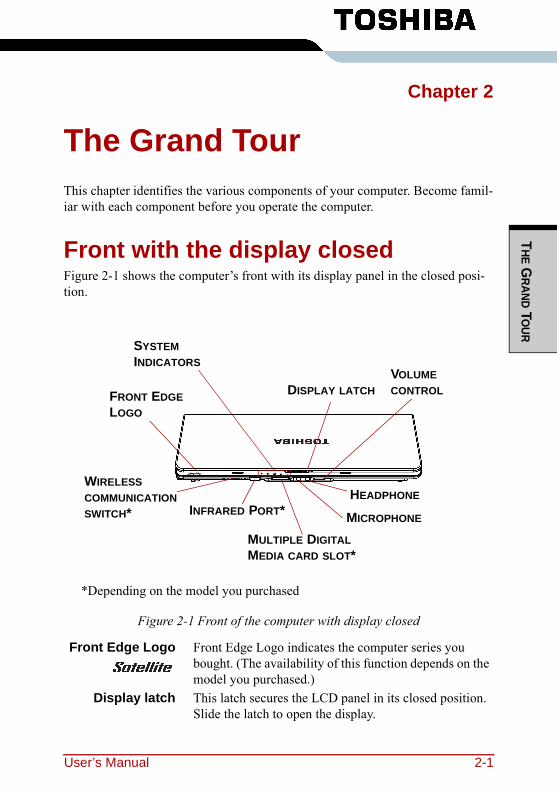
THE G
RAND TOUR
Chapter 2
The Grand TourThis chapter identifies the various components of your computer. Become famil-iar with each component before you operate the computer.
Front with the display closedFigure 2-1 shows the computer’s front with its display panel in the closed posi-tion.
Figure 2-1 Front of the computer with display closed
Front Edge Logo Front Edge Logo indicates the computer series you bought. (The availability of this function depends on the model you purchased.)
Display latch This latch secures the LCD panel in its closed position. Slide the latch to open the display.
DISPLAY LATCHVOLUME CONTROL
HEADPHONE
MICROPHONE
MULTIPLE DIGITAL MEDIA CARD SLOT*
SYSTEM INDICATORS
WIRELESS COMMUNICATION SWITCH*
FRONT EDGE LOGO
INFRARED PORT*
*Depending on the model you purchased
User’s Manual 2-1
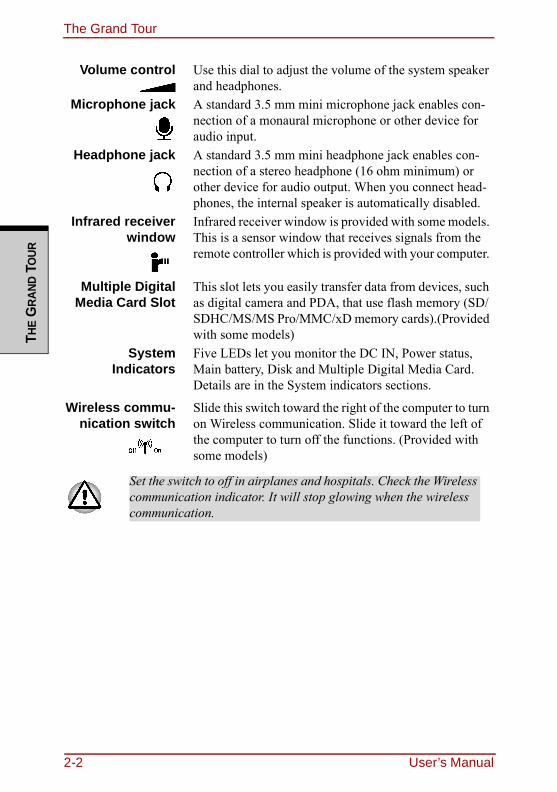
The Grand TourTH
E G
RAND
TO
UR
Volume control Use this dial to adjust the volume of the system speaker and headphones.
Microphone jack A standard 3.5 mm mini microphone jack enables con-nection of a monaural microphone or other device for audio input.
Headphone jack A standard 3.5 mm mini headphone jack enables con-nection of a stereo headphone (16 ohm minimum) or other device for audio output. When you connect head-phones, the internal speaker is automatically disabled.
Infrared receiverwindow
Infrared receiver window is provided with some models. This is a sensor window that receives signals from the remote controller which is provided with your computer.
Multiple DigitalMedia Card Slot
This slot lets you easily transfer data from devices, such as digital camera and PDA, that use flash memory (SD/SDHC/MS/MS Pro/MMC/xD memory cards).(Provided with some models)
SystemIndicators
Five LEDs let you monitor the DC IN, Power status, Main battery, Disk and Multiple Digital Media Card. Details are in the System indicators sections.
Wireless commu-nication switch
Slide this switch toward the right of the computer to turn on Wireless communication. Slide it toward the left of the computer to turn off the functions. (Provided with some models)
Set the switch to off in airplanes and hospitals. Check the Wireless communication indicator. It will stop glowing when the wireless communication.
2-2 User’s Manual
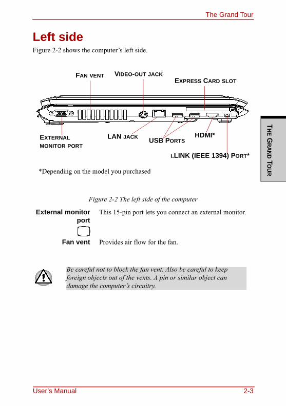
The Grand TourT
HE GRAND TO
UR
Left sideFigure 2-2 shows the computer’s left side.
Figure 2-2 The left side of the computer
External monitorport
This 15-pin port lets you connect an external monitor.
Fan vent Provides air flow for the fan.
Be careful not to block the fan vent. Also be careful to keep foreign objects out of the vents. A pin or similar object can damage the computer’s circuitry.
FAN VENT
EXTERNAL MONITOR PORT
I.LINK (IEEE 1394) PORT*
EXPRESS CARD SLOTVIDEO-OUT JACK
USB PORTSLAN JACK
*Depending on the model you purchased
HDMI*
User’s Manual 2-3
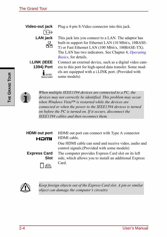
The Grand TourTH
E G
RAND
TO
UR
Video-out jack Plug a 4-pin S-Video connector into this jack.
LAN jack This jack lets you connect to a LAN. The adaptor has built-in support for Ethernet LAN (10 Mbit/s, 10BASE-T) or Fast Ethernet LAN (100 Mbit/s, 100BASE-TX). The LAN has two indicators. See Chapter 4, Operating Basics, for details.
i.LINK (IEEE1394) Port
Connect an external device, such as a digital video cam-era to this port for high-speed data transfer. Some mod-els are equipped with a i.LINK port. (Provided with some models)
When multiple IEEE1394 devices are connected to a PC, the devices may not correctly be identified. This problem may occur when Windows Vista™ is restarted while the devices are connected or when the power to the IEEE1394 devices is turned on before the PC is turned on. If it occurs, disconnect the IEEE1394 cables and then reconnect them.
HDMI out port HDMI out port can connect with Type A connector HDMI cable.One HDMI cable can send and receive video, audio and control signals.(Provided with some models)
Express CardSlot
The computer provides Express Card slot on its left side, which allows you to install an additional Express Card.
Keep foreign objects out of the Express Card slot. A pin or similar object can damage the computer’s circuitry
2-4 User’s Manual
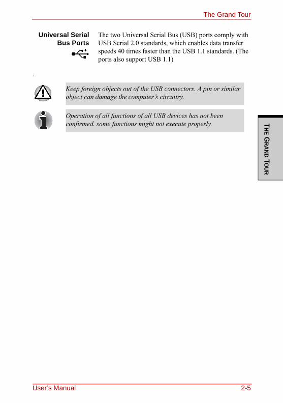
The Grand TourT
HE GRAND TO
UR
.
Universal SerialBus Ports
The two Universal Serial Bus (USB) ports comply with USB Serial 2.0 standards, which enables data transfer speeds 40 times faster than the USB 1.1 standards. (The ports also support USB 1.1)
Keep foreign objects out of the USB connectors. A pin or similar object can damage the computer’s circuitry.
Operation of all functions of all USB devices has not been confirmed. some functions might not execute properly.
User’s Manual 2-5
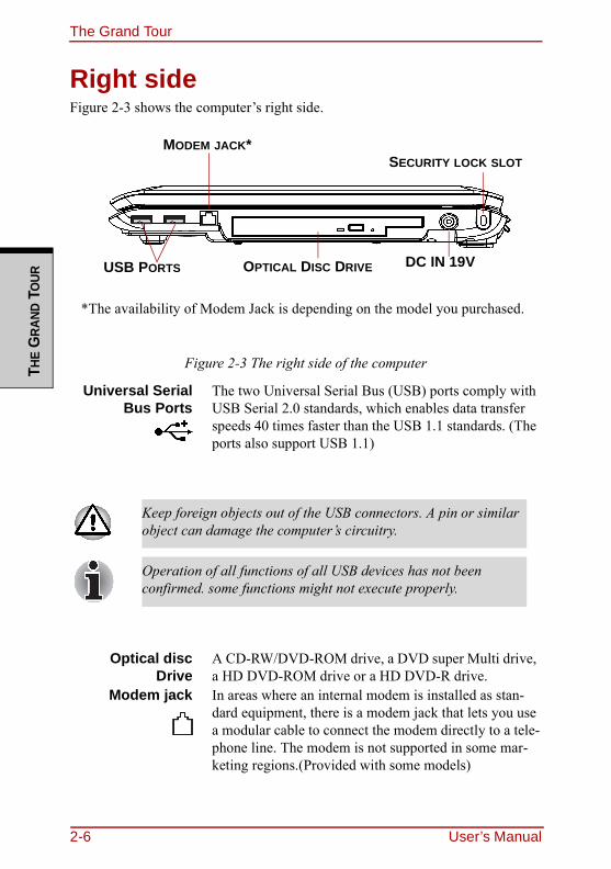
The Grand TourTH
E G
RAND
TO
UR
Right sideFigure 2-3 shows the computer’s right side.
Figure 2-3 The right side of the computer
Universal SerialBus Ports
The two Universal Serial Bus (USB) ports comply with USB Serial 2.0 standards, which enables data transfer speeds 40 times faster than the USB 1.1 standards. (The ports also support USB 1.1)
Optical discDrive
A CD-RW/DVD-ROM drive, a DVD super Multi drive, a HD DVD-ROM drive or a HD DVD-R drive.
Modem jack In areas where an internal modem is installed as stan-dard equipment, there is a modem jack that lets you use a modular cable to connect the modem directly to a tele-phone line. The modem is not supported in some mar-keting regions.(Provided with some models)
Keep foreign objects out of the USB connectors. A pin or similar object can damage the computer’s circuitry.
Operation of all functions of all USB devices has not been confirmed. some functions might not execute properly.
OPTICAL DISC DRIVEUSB PORTS
MODEM JACK*SECURITY LOCK SLOT
DC IN 19V
*The availability of Modem Jack is depending on the model you purchased.
2-6 User’s Manual
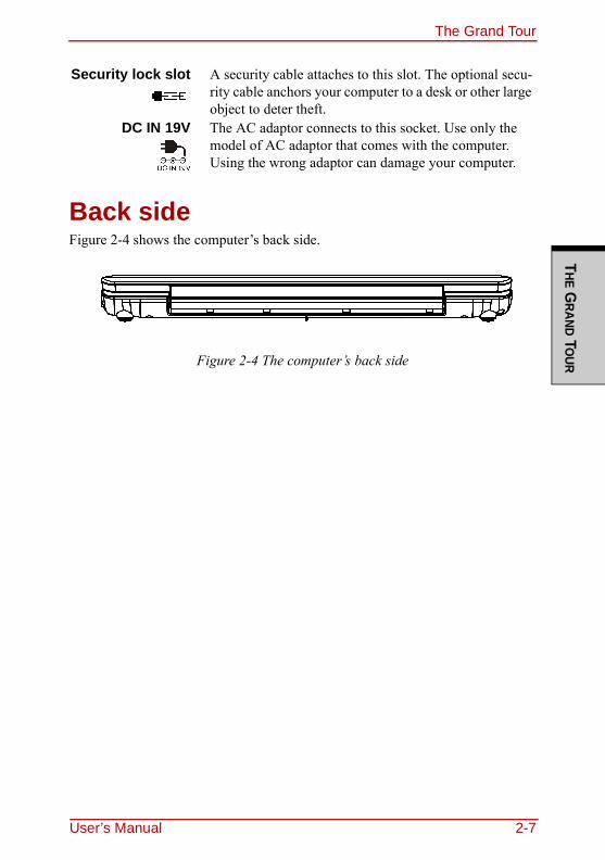
The Grand TourT
HE GRAND TO
UR
Back sideFigure 2-4 shows the computer’s back side.
Figure 2-4 The computer’s back side
Security lock slot A security cable attaches to this slot. The optional secu-rity cable anchors your computer to a desk or other large object to deter theft.
DC IN 19V The AC adaptor connects to this socket. Use only the model of AC adaptor that comes with the computer. Using the wrong adaptor can damage your computer.
User’s Manual 2-7
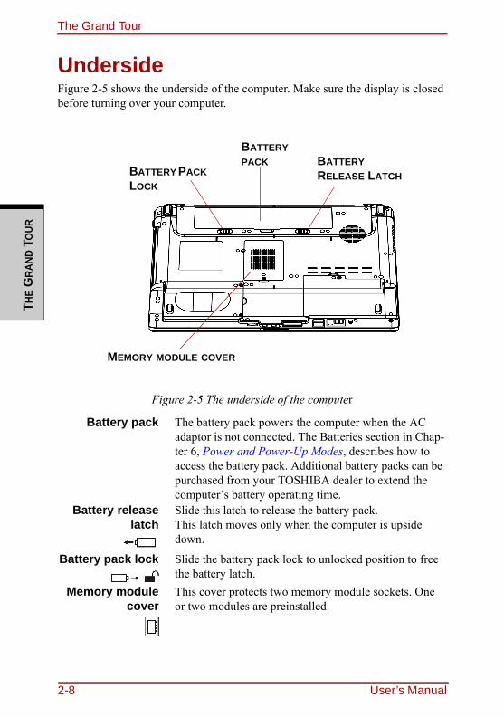
The Grand TourTH
E G
RAND
TO
UR
UndersideFigure 2-5 shows the underside of the computer. Make sure the display is closed before turning over your computer.
Figure 2-5 The underside of the computer
Battery pack The battery pack powers the computer when the AC adaptor is not connected. The Batteries section in Chap-ter 6, Power and Power-Up Modes, describes how to access the battery pack. Additional battery packs can be purchased from your TOSHIBA dealer to extend the computer’s battery operating time.
Battery releaselatch
Slide this latch to release the battery pack.This latch moves only when the computer is upside down.
Battery pack lock Slide the battery pack lock to unlocked position to free the battery latch.
Memory modulecover
This cover protects two memory module sockets. One or two modules are preinstalled.
MEMORY MODULE COVER
BATTERY PACK
BATTERY PACK LOCK
BATTERY RELEASE LATCH
2-8 User’s Manual
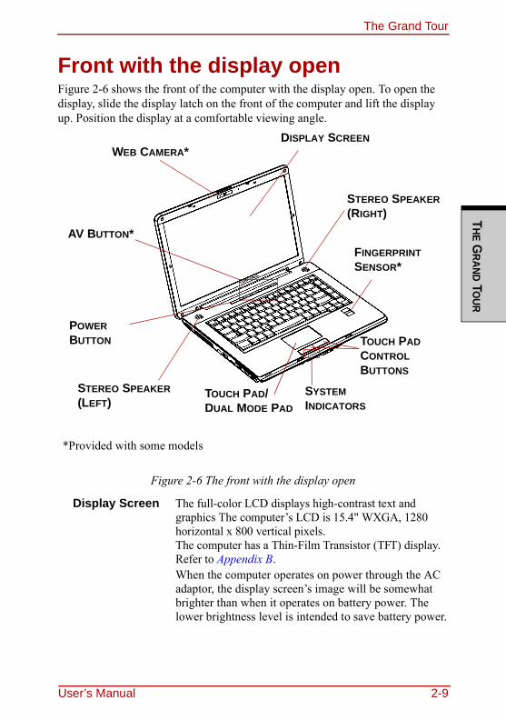
The Grand TourT
HE GRAND TO
UR
Front with the display openFigure 2-6 shows the front of the computer with the display open. To open the display, slide the display latch on the front of the computer and lift the display up. Position the display at a comfortable viewing angle.
Figure 2-6 The front with the display open
Display Screen The full-color LCD displays high-contrast text and graphics The computer’s LCD is 15.4" WXGA, 1280 horizontal x 800 vertical pixels.The computer has a Thin-Film Transistor (TFT) display. Refer to Appendix B.When the computer operates on power through the AC adaptor, the display screen’s image will be somewhat brighter than when it operates on battery power. The lower brightness level is intended to save battery power.
POWER BUTTON
STEREO SPEAKER (LEFT)
TOUCH PAD CONTROL BUTTONS
DISPLAY SCREEN
STEREO SPEAKER (RIGHT)
SYSTEM INDICATORS
AV BUTTON*FINGERPRINT SENSOR*
TOUCH PAD/DUAL MODE PAD
WEB CAMERA*
*Provided with some models
User’s Manual 2-9
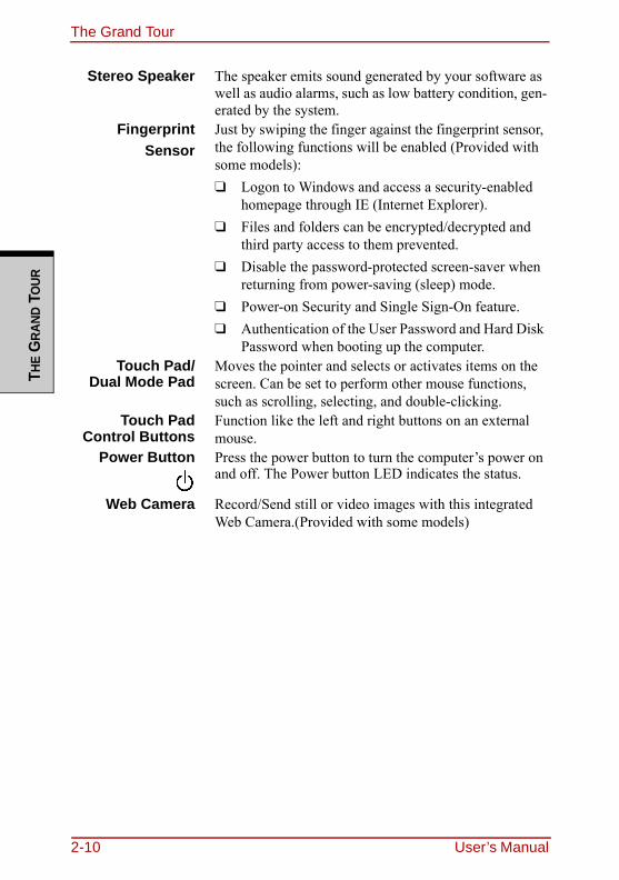
The Grand TourTH
E G
RAND
TO
UR
Stereo Speaker The speaker emits sound generated by your software as well as audio alarms, such as low battery condition, gen-erated by the system.
FingerprintSensor
Just by swiping the finger against the fingerprint sensor, the following functions will be enabled (Provided with some models):❑ Logon to Windows and access a security-enabled
homepage through IE (Internet Explorer).❑ Files and folders can be encrypted/decrypted and
third party access to them prevented.❑ Disable the password-protected screen-saver when
returning from power-saving (sleep) mode.❑ Power-on Security and Single Sign-On feature.❑ Authentication of the User Password and Hard Disk
Password when booting up the computer.Touch Pad/
Dual Mode PadMoves the pointer and selects or activates items on the screen. Can be set to perform other mouse functions, such as scrolling, selecting, and double-clicking.
Touch PadControl Buttons
Function like the left and right buttons on an external mouse.
Power Button Press the power button to turn the computer’s power on and off. The Power button LED indicates the status.
Web Camera Record/Send still or video images with this integrated Web Camera.(Provided with some models)
2-10 User’s Manual
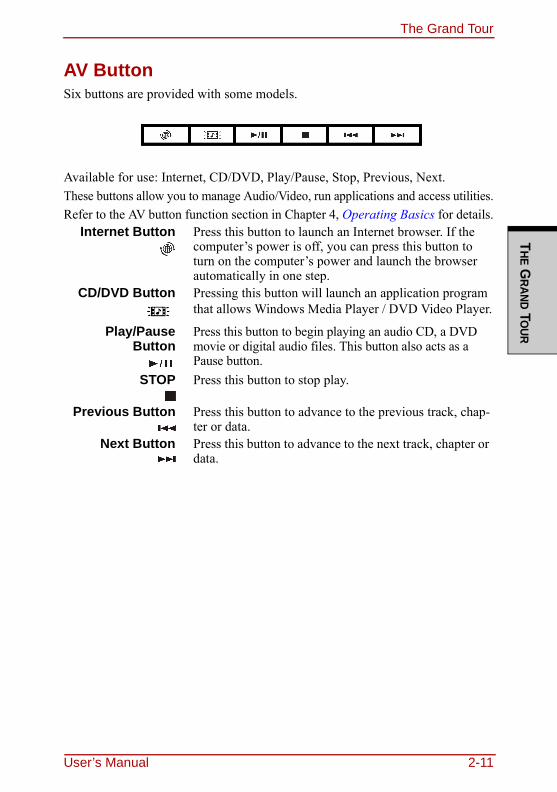
The Grand TourT
HE GRAND TO
UR
AV ButtonSix buttons are provided with some models.
Available for use: Internet, CD/DVD, Play/Pause, Stop, Previous, Next.These buttons allow you to manage Audio/Video, run applications and access utilities.Refer to the AV button function section in Chapter 4, Operating Basics for details.
Internet Button Press this button to launch an Internet browser. If the computer’s power is off, you can press this button to turn on the computer’s power and launch the browser automatically in one step.
CD/DVD Button Pressing this button will launch an application program that allows Windows Media Player / DVD Video Player.
Play/PauseButton
Press this button to begin playing an audio CD, a DVD movie or digital audio files. This button also acts as a Pause button.
STOP Press this button to stop play.
Previous Button Press this button to advance to the previous track, chap-ter or data.
Next Button Press this button to advance to the next track, chapter or data.
User’s Manual 2-11
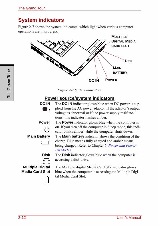
The Grand TourTH
E G
RAND
TO
UR
System indicatorsFigure 2-7 shows the system indicators, which light when various computer operations are in progress.
Figure 2-7 System indicators
Power source/system indicatorsDC IN The DC IN indicator glows blue when DC power is sup-
plied from the AC power adaptor. If the adaptor’s output voltage is abnormal or if the power supply malfunc-tions, this indicator flashes amber.
Power The Power indicator glows blue when the computer is on. If you turn off the computer in Sleep mode, this indi-cator blinks amber while the computer shuts down.
Main Battery The Main battery indicator shows the condition of the charge. Blue means fully charged and amber means being charged. Refer to Chapter 6, Power and Power-Up Modes.
Disk The Disk indicator glows blue when the computer is accessing a disk drive.
Multiple DigitalMedia Card Slot
The Multiple digital Media Card Slot indicator glows blue when the computer is accessing the Multiple Digi-tal Media Card Slot.
DC IN POWER
MAIN BATTERY
DISK
MULTIPLE DIGITAL MEDIA CARD SLOT
2-12 User’s Manual
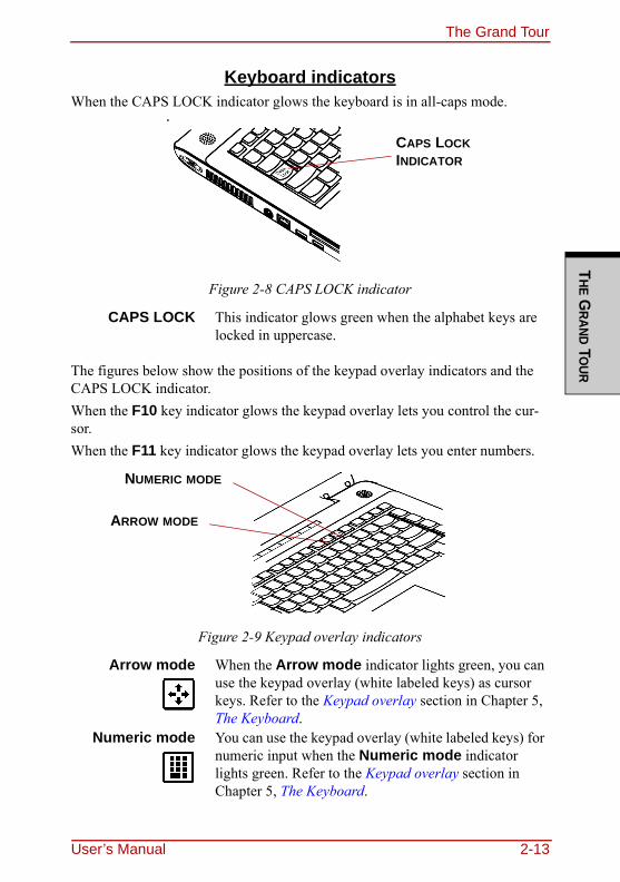
The Grand TourT
HE GRAND TO
UR
Keyboard indicatorsWhen the CAPS LOCK indicator glows the keyboard is in all-caps mode.
Figure 2-8 CAPS LOCK indicator
The figures below show the positions of the keypad overlay indicators and the CAPS LOCK indicator.When the F10 key indicator glows the keypad overlay lets you control the cur-sor.When the F11 key indicator glows the keypad overlay lets you enter numbers.
Figure 2-9 Keypad overlay indicators
CAPS LOCK This indicator glows green when the alphabet keys are locked in uppercase.
Arrow mode When the Arrow mode indicator lights green, you can use the keypad overlay (white labeled keys) as cursor keys. Refer to the Keypad overlay section in Chapter 5, The Keyboard.
Numeric mode You can use the keypad overlay (white labeled keys) for numeric input when the Numeric mode indicator lights green. Refer to the Keypad overlay section in Chapter 5, The Keyboard.
CAPS LOCK INDICATOR
ARROW MODE
NUMERIC MODE
User’s Manual 2-13
The Grand TourTH
E G
RAND
TO
UR
Optical disc driveCD-RW/DVD-ROM drive, DVD Super Multi (+-R DL) drive, HD DVD-ROM drive or a HD DVD-R drive. An ATAPI interface controller is used for CD/DVD/HD DVD-ROM operation. When the computer is accessing a CD/DVD/HD DVD, an indicator on the drive glows.
About the HD DVDThis chapter describes the features, use of HD DVD and HD DVD Media.
SummaryHD DVD allows users to enjoy video, concerts and other packaged content by taking advantage of its large amount of storage space and high-quality audio and video. HD DVD also allows for the storage of long video when combined with the latest video compression technologies.The storage capacity and data transfer rate of HD DVD is superior to standard DVD, with two types of playback-only discs in single-sided single-layer 15GB and single-sided dual-layer 30GB (Gigabyte) formats.
Notes on Use❑ Because HD DVD is a new format there is a possibility of new features
being added at a later date. As such, it is important that the purchaser under-stands that software and other updates may be necessary after purchase. Please be sure to complete user registration in order to receive timely prod-uct updates.
❑ This product can play existing DVD and CD formats, however, playback may not be possible with some software. This product cannot play Blu-ray DISCTM format software.
❑ HD DVD is a new standard which makes use of new technologies. As such, there is a possibility of problems occurring related to connection, compati-bility or operation with some discs and other digital devices. The HD DVD-ROM logo signifies that this drive complies with the HD DVD physical standard, and does not signify compliance with the HD DVD Video stan-
❑ Unfinalized DVDs created on home DVD recorders may not be playable on the computer.
❑ When inserting an unfinalized DVD-R DL disc into the com-puter, Windows Vista™ may automatically finalize the disc and prevent further writing.
2-14 User’s Manual
The Grand TourT
HE GRAND TO
UR
dard. This device does not support advanced features of the HD DVD Video standard as defined by the DVD Forum, including picture-in-picture and network dowload features. Screen movement may not be smooth, and per-formance may be lowered with some HD DVD content.
❑ Playback of high bit rate content may cause frame dropping, audio skipping or decrease in computer performance.
❑ Viewing of HD DVD content on an external display requires an HDCP capa-ble HDMITM or DVI input on the external display.
❑ Make sure to connect the computer's AC adaptor when playing an HD DVD.❑ CPU power is concentrated on HD DVD playback when playing an HD
DVD, so make sure to exit all other applications.❑ Dolby Digital audio enhancements are only supported by Microsoft® Win-
dows® operating system. Content with high sample rates of 48kHz or more are downsampled when output through either the built-in speakers or head-phone jack.
❑ This device supports AACS (Advanced Access Content System) nextgener-ation copy protection technology. Renewal of the AACS key integrated into this device is required for uninterrupted enjoyment of HD DVD. An Internet connection is required when renewing the key.
❑ For more information on AACS keys, visit the AACS website (www.aac-sla.com/home).
Region codes for DVD drives and mediaOptical disc drive and media are manufactured according to the specifications of six marketing regions. When you purchase DVD-Video, make sure it matches your drive, otherwise it will not play properly.
Code Region1 Canada, United States2 Japan, Europe, South Africa, Middle East3 Southeast Asia, East Asia4 Australia, New Zealand, Pacific Islands, Central America,
South America, Caribbean5 Russia, Indian Subcontinent, Africa, North Korea, Mongolia6 China
User’s Manual 2-15
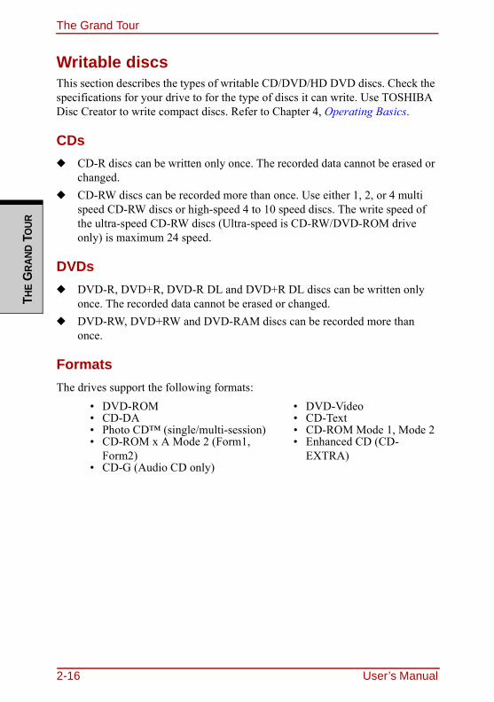
The Grand TourTH
E G
RAND
TO
UR
Writable discsThis section describes the types of writable CD/DVD/HD DVD discs. Check the specifications for your drive to for the type of discs it can write. Use TOSHIBA Disc Creator to write compact discs. Refer to Chapter 4, Operating Basics.
CDs◆ CD-R discs can be written only once. The recorded data cannot be erased or
changed.◆ CD-RW discs can be recorded more than once. Use either 1, 2, or 4 multi
speed CD-RW discs or high-speed 4 to 10 speed discs. The write speed of the ultra-speed CD-RW discs (Ultra-speed is CD-RW/DVD-ROM drive only) is maximum 24 speed.
DVDs◆ DVD-R, DVD+R, DVD-R DL and DVD+R DL discs can be written only
once. The recorded data cannot be erased or changed.◆ DVD-RW, DVD+RW and DVD-RAM discs can be recorded more than
once.
FormatsThe drives support the following formats:
• DVD-ROM • DVD-Video• CD-DA • CD-Text• Photo CD™ (single/multi-session) • CD-ROM Mode 1, Mode 2• CD-ROM x A Mode 2 (Form1,
Form2)• Enhanced CD (CD-
EXTRA)• CD-G (Audio CD only)
2-16 User’s Manual
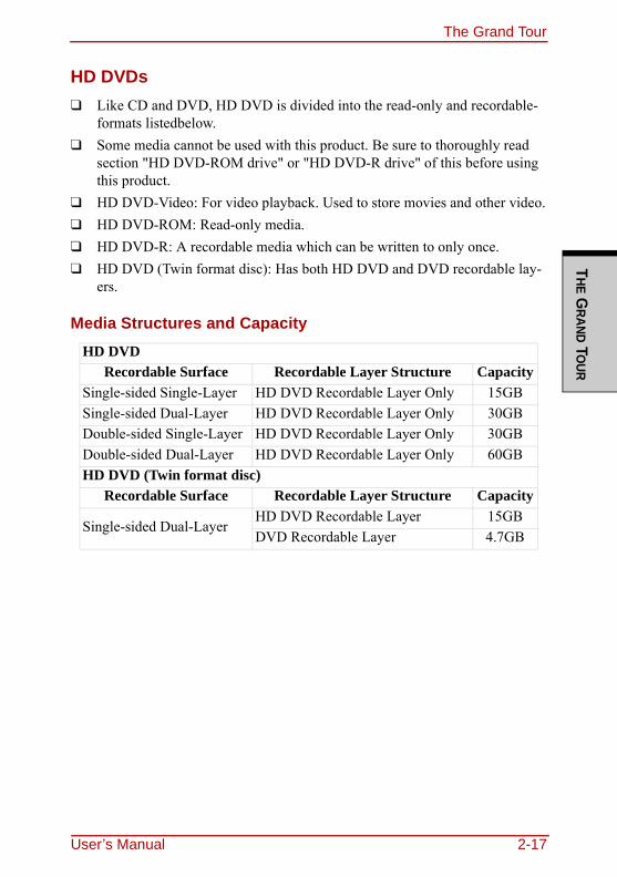
The Grand TourT
HE GRAND TO
UR
HD DVDs❑ Like CD and DVD, HD DVD is divided into the read-only and recordable-
formats listedbelow.❑ Some media cannot be used with this product. Be sure to thoroughly read
section "HD DVD-ROM drive" or "HD DVD-R drive" of this before using this product.
❑ HD DVD-Video: For video playback. Used to store movies and other video.❑ HD DVD-ROM: Read-only media.❑ HD DVD-R: A recordable media which can be written to only once.❑ HD DVD (Twin format disc): Has both HD DVD and DVD recordable lay-
ers.
Media Structures and CapacityHD DVD
Recordable Surface Recordable Layer Structure CapacitySingle-sided Single-Layer HD DVD Recordable Layer Only 15GBSingle-sided Dual-Layer HD DVD Recordable Layer Only 30GBDouble-sided Single-Layer HD DVD Recordable Layer Only 30GBDouble-sided Dual-Layer HD DVD Recordable Layer Only 60GBHD DVD (Twin format disc)
Recordable Surface Recordable Layer Structure Capacity
Single-sided Dual-LayerHD DVD Recordable Layer 15GBDVD Recordable Layer 4.7GB
User’s Manual 2-17
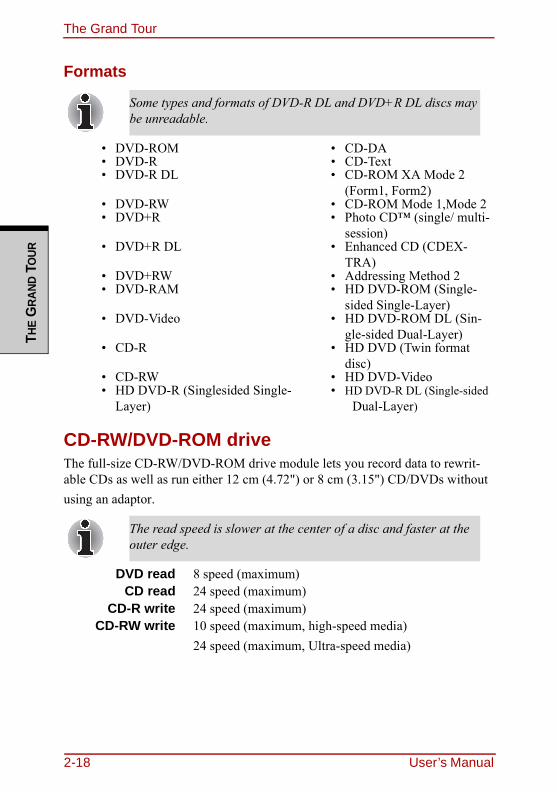
The Grand TourTH
E G
RAND
TO
UR
Formats
CD-RW/DVD-ROM driveThe full-size CD-RW/DVD-ROM drive module lets you record data to rewrit-able CDs as well as run either 12 cm (4.72") or 8 cm (3.15") CD/DVDs without using an adaptor.
Some types and formats of DVD-R DL and DVD+R DL discs may be unreadable.
• DVD-ROM • CD-DA• DVD-R • CD-Text• DVD-R DL • CD-ROM XA Mode 2
(Form1, Form2)• DVD-RW • CD-ROM Mode 1,Mode 2• DVD+R • Photo CD™ (single/ multi-
session)• DVD+R DL • Enhanced CD (CDEX-
TRA)• DVD+RW • Addressing Method 2• DVD-RAM • HD DVD-ROM (Single-
sided Single-Layer)• DVD-Video • HD DVD-ROM DL (Sin-
gle-sided Dual-Layer)• CD-R • HD DVD (Twin format
disc)• CD-RW • HD DVD-Video• HD DVD-R (Singlesided Single-
Layer)• HD DVD-R DL (Single-sided
Dual-Layer)
The read speed is slower at the center of a disc and faster at the outer edge.
DVD read 8 speed (maximum)CD read 24 speed (maximum)
CD-R write 24 speed (maximum)CD-RW write 10 speed (maximum, high-speed media)
24 speed (maximum, Ultra-speed media)
2-18 User’s Manual
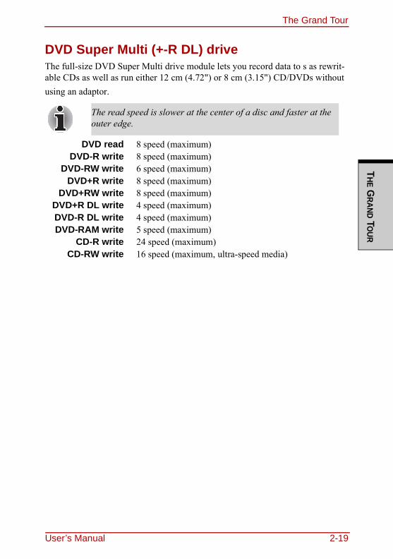
The Grand TourT
HE GRAND TO
UR
DVD Super Multi (+-R DL) driveThe full-size DVD Super Multi drive module lets you record data to s as rewrit-able CDs as well as run either 12 cm (4.72") or 8 cm (3.15") CD/DVDs without using an adaptor.
The read speed is slower at the center of a disc and faster at the outer edge.
DVD read 8 speed (maximum)DVD-R write 8 speed (maximum)
DVD-RW write 6 speed (maximum)DVD+R write 8 speed (maximum)
DVD+RW write 8 speed (maximum)DVD+R DL write 4 speed (maximum)DVD-R DL write 4 speed (maximum)DVD-RAM write 5 speed (maximum)
CD-R write 24 speed (maximum)CD-RW write 16 speed (maximum, ultra-speed media)
User’s Manual 2-19
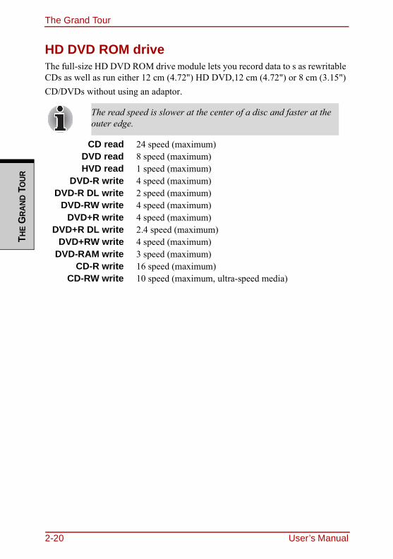
The Grand TourTH
E G
RAND
TO
UR
HD DVD ROM drive
The full-size HD DVD ROM drive module lets you record data to s as rewritable CDs as well as run either 12 cm (4.72") HD DVD,12 cm (4.72") or 8 cm (3.15") CD/DVDs without using an adaptor.
The read speed is slower at the center of a disc and faster at the outer edge.
CD read 24 speed (maximum)DVD read 8 speed (maximum)HVD read 1 speed (maximum)
DVD-R write 4 speed (maximum)DVD-R DL write 2 speed (maximum)
DVD-RW write 4 speed (maximum)DVD+R write 4 speed (maximum)
DVD+R DL write 2.4 speed (maximum)DVD+RW write 4 speed (maximum)
DVD-RAM write 3 speed (maximum)CD-R write 16 speed (maximum)
CD-RW write 10 speed (maximum, ultra-speed media)
2-20 User’s Manual
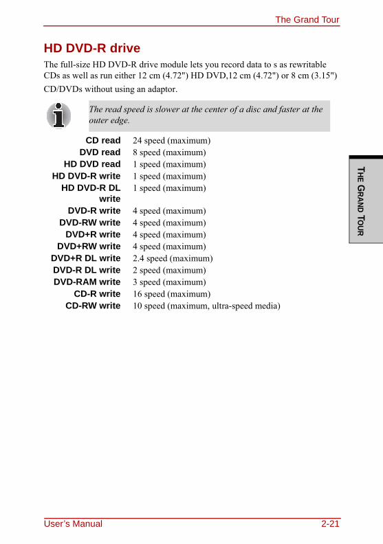
The Grand TourT
HE GRAND TO
UR
HD DVD-R driveThe full-size HD DVD-R drive module lets you record data to s as rewritable CDs as well as run either 12 cm (4.72") HD DVD,12 cm (4.72") or 8 cm (3.15") CD/DVDs without using an adaptor.
The read speed is slower at the center of a disc and faster at the outer edge.
CD read 24 speed (maximum)DVD read 8 speed (maximum)
HD DVD read 1 speed (maximum)HD DVD-R write 1 speed (maximum)
HD DVD-R DLwrite
1 speed (maximum)
DVD-R write 4 speed (maximum)DVD-RW write 4 speed (maximum)
DVD+R write 4 speed (maximum)DVD+RW write 4 speed (maximum)
DVD+R DL write 2.4 speed (maximum)DVD-R DL write 2 speed (maximum)DVD-RAM write 3 speed (maximum)
CD-R write 16 speed (maximum)CD-RW write 10 speed (maximum, ultra-speed media)
User’s Manual 2-21
The Grand TourTH
E G
RAND
TO
UR
Remote ControllerYour computer includes a Remote Controller which enables you to perform some functions of your computer from a distant location.The following figure shows the buttons on the Remote Controller.Your can use your Remote Controller with Media Center to play CDs, DVDs and videos, to view pictures and to watch and record television programs.The Remote Controller helps you to control the playback of a movie through Media Center .Using the Remote Controller, you can:❑ Navigate and control all Media Center windows.❑ Control the video.❑ Place the computer in and out of Sleep Mode.
2-22 User’s Manual
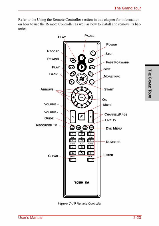
The Grand TourT
HE GRAND TO
UR
Refer to the Using the Remote Controller section in this chapter for information on how to use the Remote Controller as well as how to install and remove its bat-teries.
Figure 2-10 Remote Controller
PAUSE
POWER
PLAY
RECORDSTOP
FAST FORWARD
SKIP
MORE INFO
START
OK
MUTE
REWIND
PLAY
BACK
ARROWS
CHANNEL/PAGE
LIVE TV
DVD MENU
NUMBERS
ENTER
VOLUME +
VOLUME -
GUIDE
RECORDED TV
CLEAR
User’s Manual 2-23
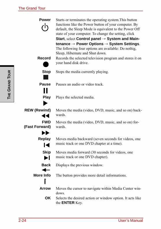
The Grand TourTH
E G
RAND
TO
UR
Power Starts or terminates the operating system.This button functions like the Power button of your computer. By default, the Sleep Mode is equivalent to the Power Off state of your computer. To change the setting, click Start, select Control panel → System and Main-tenance → Power Options → System Settings. The following four options are available: Do nothig, Sleep, Hibernate and Shut down.
Record Records the selected television program and stores it on your hand disk drive.
Stop Stops the media currently playing.
Pause Pauses an audio or video track.
Play Plays the selected media.
REW (Rewind) Moves the media (video, DVD, music, and so on) back-wards.
FWD(Fast Forward)
Moves the media (video, DVD, music, and so on) for-wards.
Replay Moves media backward (seven seconds for videos, one music track or one DVD chapter at a time).
Skip Moves media forward (30 seconds for videos, one music track or one DVD chapter).
Back Displays the previous window.
More Info The button provides more detail informations.
Arrow Moves the cursor to navigate within Media Center win-dows.
OK Selects the desired action or window option. It acts like the ENTER Key.
2-24 User’s Manual
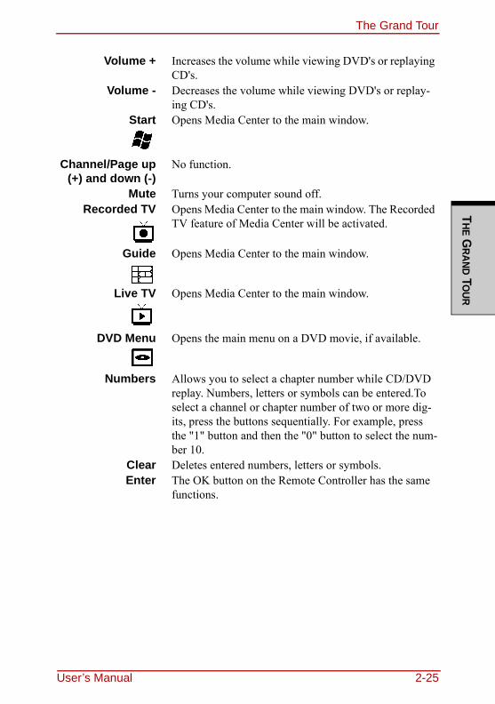
The Grand TourT
HE GRAND TO
UR
Volume + Increases the volume while viewing DVD's or replaying CD's.
Volume - Decreases the volume while viewing DVD's or replay-ing CD's.
Start Opens Media Center to the main window.
Channel/Page up(+) and down (-)
No function.
Mute Turns your computer sound off.Recorded TV Opens Media Center to the main window. The Recorded
TV feature of Media Center will be activated.
Guide Opens Media Center to the main window.
Live TV Opens Media Center to the main window.
DVD Menu Opens the main menu on a DVD movie, if available.
Numbers Allows you to select a chapter number while CD/DVD replay. Numbers, letters or symbols can be entered.To select a channel or chapter number of two or more dig-its, press the buttons sequentially. For example, press the "1" button and then the "0" button to select the num-ber 10.
Clear Deletes entered numbers, letters or symbols.Enter The OK button on the Remote Controller has the same
functions.
User’s Manual 2-25
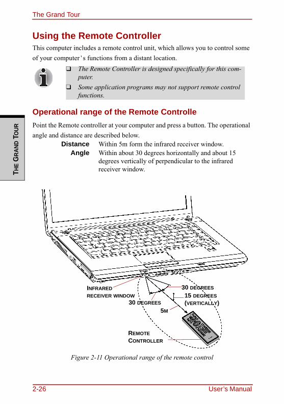
The Grand TourTH
E G
RAND
TO
UR
Using the Remote ControllerThis computer includes a remote control unit, which allows you to control some of your computer's functions from a distant location.
Operational range of the Remote ControllePoint the Remote controller at your computer and press a button. The operational angle and distance are described below.
Figure 2-11 Operational range of the remote control
❑ The Remote Controller is designed specifically for this com-puter.
❑ Some application programs may not support remote control functions.
Distance Within 5m form the infrared receiver window.Angle Within about 30 degrees horizontally and about 15
degrees vertically of perpendicular to the infrared receiver window.
REMOTE CONTROLLER
INFRARED RECEIVER WINDOW
30 DEGREES
30 DEGREES15 DEGREES (VERTICALLY)
5M
2-26 User’s Manual
The Grand TourT
HE GRAND TO
UR
*The appearance of the provided Remote Controller may vary from model to model, and it is not provided with some model.
Installing/Removing batteriesBe sure to install the dry batteries provided with this product before using the Remote Controller.The procedures for installing and removing the batteries vary depending on the type of the Remote Controller. Check the type and then install or remove the batteries as instructed.
Even if within the effective scope as described above, the remote control may malfunction or not work correctly in the following cases.❑ When an obstacle stands between the infrared receiver win-
dow of your computer and the Remote Controller❑ When direct sunlight or strong fluorescent light strikes the
infrared receiver window.❑ When the infrared receiver window or the infrared emission
part of the Remote Controller is dirty.❑ When other computers which use an infrared remote control-
ler are used near to your computer.❑ When a low battery condition is present.
Store the battery for the remote control beyond the reach of children.If a child swallows a battery, this might result in choking. If it happens, contact a doctor immediately.
User’s Manual 2-27
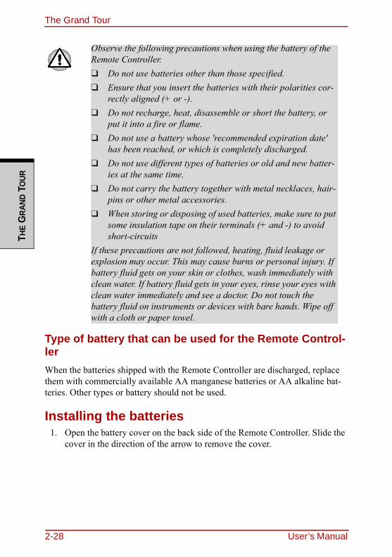
The Grand TourTH
E G
RAND
TO
UR
Type of battery that can be used for the Remote Control-lerWhen the batteries shipped with the Remote Controller are discharged, replace them with commercially available AA manganese batteries or AA alkaline bat-teries. Other types or battery should not be used.
Installing the batteries1. Open the battery cover on the back side of the Remote Controller. Slide the
cover in the direction of the arrow to remove the cover.
Observe the following precautions when using the battery of the Remote Controller.❑ Do not use batteries other than those specified.❑ Ensure that you insert the batteries with their polarities cor-
rectly aligned (+ or -).❑ Do not recharge, heat, disassemble or short the battery, or
put it into a fire or flame.❑ Do not use a battery whose 'recommended expiration date'
has been reached, or which is completely discharged. ❑ Do not use different types of batteries or old and new batter-
ies at the same time.❑ Do not carry the battery together with metal necklaces, hair-
pins or other metal accessories.❑ When storing or disposing of used batteries, make sure to put
some insulation tape on their terminals (+ and -) to avoid short-circuits
If these precautions are not followed, heating, fluid leakage or explosion may occur. This may cause burns or personal injury. If battery fluid gets on your skin or clothes, wash immediately with clean water. If battery fluid gets in your eyes, rinse your eyes with clean water immediately and see a doctor. Do not touch the battery fluid on instruments or devices with bare hands. Wipe off with a cloth or paper towel.
2-28 User’s Manual
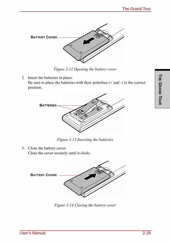
The Grand TourT
HE GRAND TO
UR
Figure 2-12 Opening the battery cover
2. Insert the batteries in place. Be sure to place the batteries with their polarities (+ and -) in the correct position.
Figure 2-13 Inserting the batteries
3. Close the battery cover.Close the cover securely until it clicks
Figure 2-14 Closing the battery cover
BATTERY COVER
BATTERIES
BATTERY COVER
User’s Manual 2-29
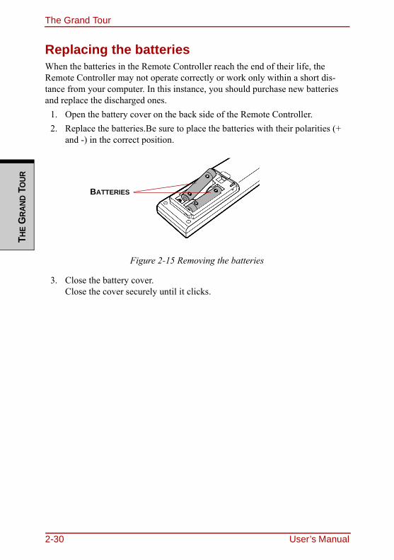
The Grand TourTH
E G
RAND
TO
UR
Replacing the batteriesWhen the batteries in the Remote Controller reach the end of their life, the Remote Controller may not operate correctly or work only within a short dis-tance from your computer. In this instance, you should purchase new batteries and replace the discharged ones.
1. Open the battery cover on the back side of the Remote Controller.2. Replace the batteries.Be sure to place the batteries with their polarities (+
and -) in the correct position.
Figure 2-15 Removing the batteries
3. Close the battery cover.Close the cover securely until it clicks.
BATTERIES
2-30 User’s Manual
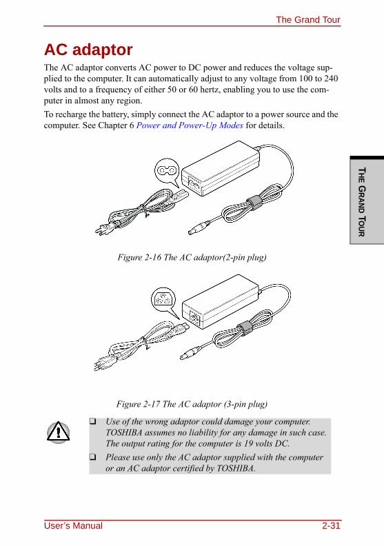
The Grand TourT
HE GRAND TO
UR
AC adaptorThe AC adaptor converts AC power to DC power and reduces the voltage sup-plied to the computer. It can automatically adjust to any voltage from 100 to 240 volts and to a frequency of either 50 or 60 hertz, enabling you to use the com-puter in almost any region.To recharge the battery, simply connect the AC adaptor to a power source and the computer. See Chapter 6 Power and Power-Up Modes for details.
Figure 2-16 The AC adaptor(2-pin plug)
Figure 2-17 The AC adaptor (3-pin plug)
❑ Use of the wrong adaptor could damage your computer. TOSHIBA assumes no liability for any damage in such case. The output rating for the computer is 19 volts DC.
❑ Please use only the AC adaptor supplied with the computer or an AC adaptor certified by TOSHIBA.
User’s Manual 2-31

The Grand TourTH
E G
RAND
TO
UR
2-32 User’s Manual
User’s Manual 3-1
GETTING S
TARTED
Chapter 3
Getting StartedThis chapter provides basic information to get you started using your computer. It covers the following topics:
❑ Connecting the AC adaptor❑ Opening the display❑ Turning on the power❑ Starting up for the first time❑ Turning off the power❑ Restarting the computer❑ System Recovery OptionsIf you are a new user, follow the steps in each section of this chapter as you pre-pare to operate your computer.
Be sure also to read Instruction Manual for Safety & Comfort. This guide, which is included with the computer, explains product liability.
All users should be sure to carefully read the sections Windows Vista™ setup, which describe actions to take when you turn on the power for the first time.
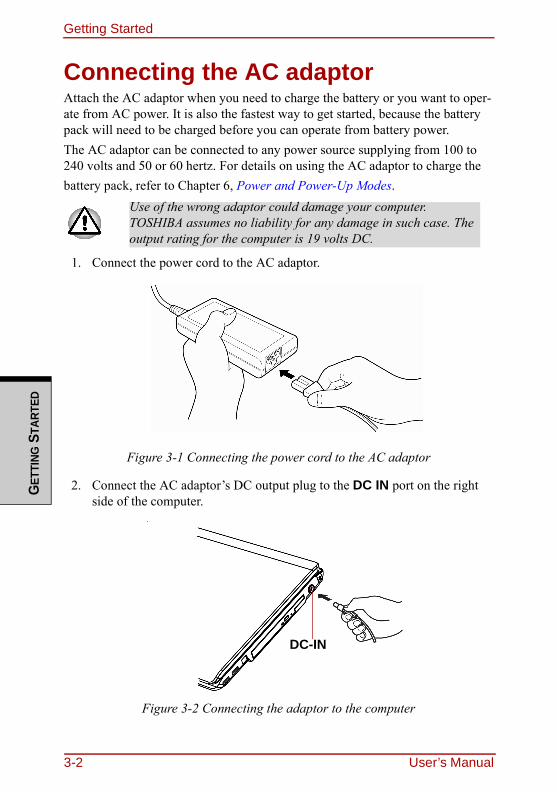
Getting StartedG
ETTI
NG S
TART
ED
Connecting the AC adaptorAttach the AC adaptor when you need to charge the battery or you want to oper-ate from AC power. It is also the fastest way to get started, because the battery pack will need to be charged before you can operate from battery power.The AC adaptor can be connected to any power source supplying from 100 to 240 volts and 50 or 60 hertz. For details on using the AC adaptor to charge the battery pack, refer to Chapter 6, Power and Power-Up Modes.
1. Connect the power cord to the AC adaptor.
Figure 3-1 Connecting the power cord to the AC adaptor
2. Connect the AC adaptor’s DC output plug to the DC IN port on the right side of the computer.
Figure 3-2 Connecting the adaptor to the computer
Use of the wrong adaptor could damage your computer. TOSHIBA assumes no liability for any damage in such case. The output rating for the computer is 19 volts DC.
DC-IN
3-2 User’s Manual
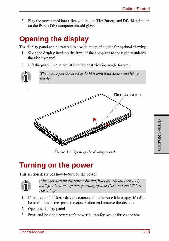
Getting StartedG
ETTING STARTED
3. Plug the power cord into a live wall outlet. The Battery and DC IN indicator on the front of the computer should glow.
Opening the displayThe display panel can be rotated in a wide range of angles for optimal viewing.
1. Slide the display latch on the front of the computer to the right to unlatch the display panel.
2. Lift the panel up and adjust it to the best viewing angle for you.
.
Figure 3-3 Opening the display panel
Turning on the powerThis section describes how to turn on the power.
1. If the external diskette drive is connected, make sure it is empty. If a dis-kette is in the drive, press the eject button and remove the diskette.
2. Open the display panel.3. Press and hold the computer’s power button for two or three seconds.
When you open the display, hold it with both hands and lift up slowly.
After you turn on the power for the first time, do not turn it off until you have set up the operating system (OS) and the OS has started up.
DISPLAY LATCH
User’s Manual 3-3
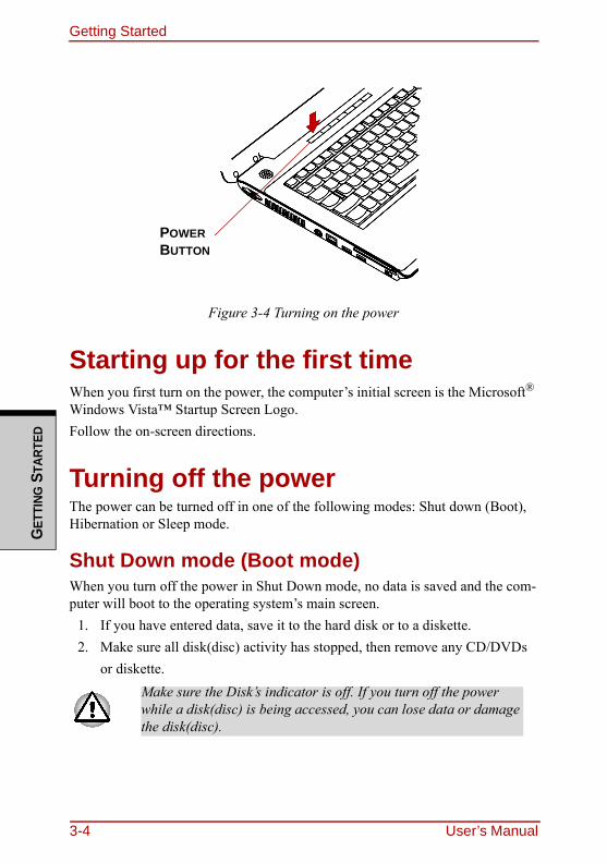
Getting StartedG
ETTI
NG S
TART
ED
Figure 3-4 Turning on the power
Starting up for the first timeWhen you first turn on the power, the computer’s initial screen is the Microsoft® Windows Vista™ Startup Screen Logo.Follow the on-screen directions.
Turning off the powerThe power can be turned off in one of the following modes: Shut down (Boot), Hibernation or Sleep mode.
Shut Down mode (Boot mode)When you turn off the power in Shut Down mode, no data is saved and the com-puter will boot to the operating system’s main screen.
1. If you have entered data, save it to the hard disk or to a diskette.2. Make sure all disk(disc) activity has stopped, then remove any CD/DVDs
or diskette.Make sure the Disk’s indicator is off. If you turn off the power while a disk(disc) is being accessed, you can lose data or damage the disk(disc).
POWER BUTTON
3-4 User’s Manual
Getting StartedG
ETTING STARTED
3. Click Windows Start button, point to , and then select Shut Down.
4. Turn off the power to any peripheral devices.
Hibernation modeThe hibernation feature saves the contents of memory to the hard disk when the computer is turned off. The next time the computer is turned on, the previous state is restored. The hibernation feature does not save the status of peripheral devices.
Benefits of hibernationThe hibernation feature provides the following benefits:❑ Saves data to the hard disk when the computer automatically shuts down
because of a low battery.
❑ You can return to your previous working environment immediately when you turn on the computer.
❑ Saves power by shutting down the system when the computer receives no input or hardware access for the duration set by the System hibernate fea-ture.
❑ You can use the panel power off feature.
Do not turn the computer or devices back on immediately. Wait a moment to let all capacitors fully discharge.
❑ While entering hibernation mode, the computer saves the contents of memory to the HDD. Data will be lost if you remove the battery or disconnect the AC adaptor before the save is completed. Wait for the Disk indicator to go out.
❑ Do not install or remove a memory module while the com-puter is in hibernation mode. Data will be lost.
For the computer to shut down in hibernation mode, the hibernation feature must be enabled in two places: the Hibernate tab in Power Options and Setup Action tab in TOSHIBA Power Saver. Otherwise, the computer will shut down in Sleep mode. If battery power becomes depleted, data saved in Sleep mode will be lost.
User’s Manual 3-5
Getting StartedG
ETTI
NG S
TART
ED
Starting HibernationTo enter Hibernation mode, follow the steps below.
Windows Vista™
1. Click Windows Start button.
2. Point to .3. Select Hibernate.
Automatic HibernationThe computer will enter Hibernate mode automatically when you press the power button or close the lid. First, however, make the appropriate settings according to the steps below.
1. Open the Control Panel.2. Open Mobile PC and open Power Options.3. Select Choose what the power button does.4. Enable the desired Hibernation settings for When I press the power
button and When I close the lid.5. Click the Save changes button.
Data save in hibernation modeWhen you turn off the power in hibernation mode, the computer takes a moment to save current memory data to the hard disk. During this time, the Built-in HDD indicator will light.After you turn off the computer and memory is saved to the hard disk, turn off the power to any peripheral devices.
Do not turn the computer or devices back on immediately. Wait a moment to let all capacitors fully discharge.
3-6 User’s Manual
Getting StartedG
ETTING STARTED
Sleep modeIn sleep mode the power remains on, but the CPU and all other devices are in sleep mode.
Benefits of sleepThe sleep feature provides the following benefits:❑ Restores the previous working environment more rapidly than does hiberna-
tion.❑ Saves power by shutting down the system when the computer receives no
input or hardware access for the duration set by the System Sleep feature.❑ You can use the panel power off feature.
Executing sleep
You can enter sleep mode in one of three ways:
1. Click Windows Start button, point to , and then click Sleep.2. Close the display panel. This feature must be enabled. Refer to the Power
Options in the Control Panel. 3. Press the power button. This feature must be enabled. Refer to the Power
Option in the Control Panel.
❑ Before entering Sleep mode, be sure to save your data.❑ Do not install or remove a memory module while the com-
puter is in sleep mode. The computer or the module could be damaged.
❑ Do not remove the battery pack while the computer is in sleep mode (unless the computer is connected to an AC power source). Data in memory will be lost.
You can also enable Sleep by pressing FN+F3. See Chapter 5, The Keyboard, for details.
User’s Manual 3-7
Getting StartedG
ETTI
NG S
TART
ED
When you turn the power back on, you can continue where you left when you shut down the computer.
Sleep limitationsSleep will not function under the following conditions:❑ Power is turned back on immediately after shutting down.❑ Memory circuits are exposed to static electricity or electrical noise.
Restarting the computerCertain conditions require that you restart the computer system. For example, if:❑ You change certain computer settings.❑ An error occurs and the computer does not respond to your keyboard com-
mands.If you need to restart the computer, there are three ways this can be achieved:
1. Click Start, then click the narrow ( ) in the power management button ( ) and select Restart from the menu.
2. Press CTRL + ALT + DEL to display the menu window, then select Restart from the Shut down options.
3. Press the power button and hold it down for five seconds. Once the com-puter has turned itself off, wait between ten and fifteen seconds before turn-ing the power on again by pressing the power button.
❑ When the computer is shut down in sleep mode, the power indicator glows amber.
❑ If you are operating the computer on battery power, you can lengthen the operating time by shutting down in hibernation mode. Sleep mode consumes more power.
3-8 User’s Manual
Getting StartedG
ETTING STARTED
System Recovery OptionsAbout 1.5GB hidden partition is allocated on the hard disk drive for the System Recovery Options. This partition stores files which can be used to repair the sys-tem in the event of a problem.
System Recovery OptionsThe System Recovery Options feature is installed on the hard disk when shipped from the factory. The System Recovery Options menu includes some tools to repair startup problems, run diagnostics or restore the system.You can see the more information about “Startup Repair” in “Windows Help and Support” content.The System Recovery Options can also be run manually to repair problems.
1. Turn off the computer.2. While holding the F8 key, turn the computer on again.3. The Advanced Boot Options menu will be displayed. Use the arrow
keys to select Repair Your Computer and press ENTER.
4. Follow the on-screen instructions from this point onward.
The Window Vista Complete PC Backup feature can be used on Windows Vista™ Business Edition and Ultimate Edition.
User’s Manual 3-9
Getting StartedG
ETTI
NG S
TART
ED
Create Optical Recovery DiscsFor HDD Recovery modelA recovery image of your computer is stored on the hard disk. You may use this image to create CD or DVD recovery discs using the following steps:
1. Select either blank CDs or DVDs media.2. The application will allow you to choose a type of media to create recovery
CDs/DVD including: CD-R, CD-RW, DVD-R, DVD-RW, DVD+R, DVD+RW, DVD+R DL and DVD-R DL.
3. Turn on your computer to open Windows Vista™.4. Insert the (first) blank media into the tray of the Optical Drive.5. Double click the Recovery Disc Creator icon on the Windows Vista™ desk-
top, or Select the application from Start Menu.6. After Recovery Disc Creator starts, select the type of media and the title
you wish to copy to the media then click the Burn.
Restoring the preinstalled software from the Recovery HDDFor HDD Recovery modelA portion of the total hard disk drive space is configured as a hidden recovery partition. This partition stores files which can be used to restore pre-stalled soft-ware in the event of a problem.When re-setting up your hard disk, do not change, delete or add partition in a manner other than specified in the manual. Otherwise, space for software may be destroyed.
Some media may not be compatible with Optical Drive of your computer. Please verify your Optical Drive supports the blank media you choose.
If your Optical Drive can only write to CDs, select "CD" as the "Disc Set" on Recovery Disc Creator. If your Optical Drive of your computer can write to either CD or DVDs, select the one you are using as the "Disc Set" on Recovery Disc Creator.
3-10 User’s Manual
Getting StartedG
ETTING STARTED
In addition, if you use a third-party partitioning program to reconfigure partitions on your hard disk, it may become impossible to re-setup your computer.You can not use System Recovery Options if restoring the pre-installed software without System Recovery Options.
1. Turn off your computer.2. While holding down 0 (zero) key on the keyboard, turn on your computer.3. A menu appears. Follow the on-screen instructions.
Restoring the preinstalled software from your creating Recovery MediaFor HDD Recovery modelIf preinstalled files are damaged, use the your creating Recovery Media or using HDD Recovery to restore them. To restore the operating system and all prein-stalled software, follow the steps below.You can not use System Recovery Options if restoring the pre-installed softwarewithout System Recovery Options.
1. Load the Recovery Media in the optional optical disc drive and turn off the computer's power.
2. Hold down the F12 key and turn on the power. When In Touch with Tomorrow TOSHIBA appears, release the F12 key.
When you reinstall the Windows operating system, the hard disk will be reformatted and all data will be lost.
For 2HDDs model,If HDD1 is first, go to the (3.) step.If HDD1 is not first, do as follows.
a. Select <Enter Setup>b. Press the F9 key to set to default settings, and select the [Yes].c. Press the F10 key to save the changes, and select the [Yes].d. When the "In Touch with Tomorrow TOSHIBA" prompt
appears, press the F12 key to display the Boot menu.
Go to the (3.)step.
User’s Manual 3-11
Getting StartedG
ETTI
NG S
TART
ED
3. Use the up or down cursor key to select CD/DVD in the display menu. For details, refer to the Boot Priority section in Chapter 7, HW Setup and Pass-words.
4. A menu appears. Follow the on-screen instructions.
When drivers Utilities are installed, you can setup the respective drivers and utilities from the following folder. C: \ TOSAPINS\***
When removing pre-installed drivers/utilities or when installing, you can setup the respective drivers/utilities from the following folder. C:\TOSAPINS\***
3-12 User’s Manual
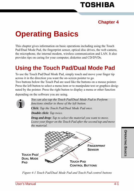
OPERATING B
ASICS
Chapter 4
Operating BasicsThis chapter gives information on basic operations including using the Touch Pad/Dual Mode Pad, the fingerprint sensor, optical disc drives, the web camera, the microphone, the internal modem, wireless communication and LAN. It also provides tips on caring for your computer, diskettes and CD/DVDs.
Using the Touch Pad/Dual Mode PadTo use the Touch Pad/Dual Mode Pad, simply touch and move your finger tip across it in the direction you want the on-screen pointer to go.Two buttons below the Touch Pad are used like the buttons on a mouse pointer.Press the left button to select a menu item or to manipulate text or graphics desig-nated by the pointer. Press the right button to display a menu or other function depending on the software you are using.
Figure 4-1 Touch Pad/Dual Mode Pad and Touch Pad control buttons
You can also tap the Touch Pad/Dual Mode Pad to Perform functions similar to those of the left button.Click: Tap the Touch Pad/Dual Mode Pad once.Double click: Tap twice.Drag and drop: Tap to select the material you want to move. Leave your finger on the Touch Pad after the second tap and move the material.
TOUCH PAD/DUAL MODE PAD TOUCH PAD
CONTROL BUTTONS
FINGERPRINT SENSOR
User’s Manual 4-1
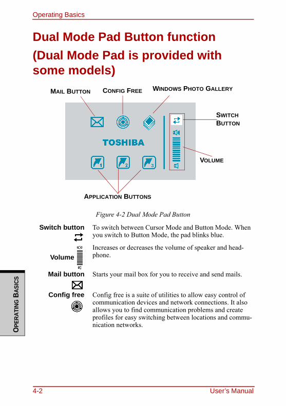
Operating BasicsO
PERA
TING
BAS
ICS
Dual Mode Pad Button function(Dual Mode Pad is provided with some models)
Figure 4-2 Dual Mode Pad Button
Switch button To switch between Cursor Mode and Button Mode. When you switch to Button Mode, the pad blinks blue.
VolumeIncreases or decreases the volume of speaker and head-phone.
Mail button Starts your mail box for you to receive and send mails.
Config free Config free is a suite of utilities to allow easy control of communication devices and network connections. It also allows you to find communication problems and create profiles for easy switching between locations and commu-nication networks.
APPLICATION BUTTONS
VOLUME
CONFIG FREEMAIL BUTTON WINDOWS PHOTO GALLERY
SWITCH BUTTON
4-2 User’s Manual
Operating BasicsO
PERATING BASICS
Using the Fingerprint SensorThis product has a fingerprint utility installed for the purpose of enrolling and recognizing fingerprints. By enrolling the ID and password to the fingerprint authentication device, it is no longer necessary to input the password from the keyboard. Just by swiping the finger against the fingerprint sensor, the following functions will be enabled:❑ Logon to Windows and access a security-enabled homepage through IE
(Internet Explorer).❑ Files and folders can be encrypted/decrypted and third party access to them
prevented.❑ Disable the password-protected screen-saver when returning from power-
saving (sleep) mode.❑ Power-on Security and Single Sign-On feature.❑ Authentication of the User Password and Hard Disk Password when booting
up the computer.
Windows PhotoGallery
Windows Photo Gallery gives you many tools for your digi-tal photos and videos.You can organize, find, and view your photos and videos, as well as edit, print, and share them from within Windows Photo Gallery. It also makes it easy to transfer your photos from your camera to your computer, using a simple import process
Applicationbuttons
Three application buttons have default setting. You can assign other functions and programs to button 1 to 3.
Please refer to "Properties for synaptics Dual Mode Pad" for details.
To “swipe”refers to the action of reading a fingerprint using the fingerprint sensor.
User’s Manual 4-3
Operating BasicsO
PERA
TING
BAS
ICS
Points to note about the Fingerprint SensorFailure to follow these guidelines might result in (1) damage to the sensor or cause sensor failure, (2) finger recognition problems, or lower finger recognition success rate. ❑ Do not scratch or poke the sensor with your nails or any hard or sharp
objects.❑ Do not press the sensor strongly.❑ Do not touch the sensor with a wet finger or any wet objects. Keep sensor
surface dry and free of water vapor.❑ Do not touch the sensor with a soiled finger. Minute foreign particles on a
soiled or dirty finger may scratch the sensor.❑ Do not paste stickers or write on the sensor.❑ Do not touch the sensor with a finger or any object with built-up static elec-
tricity.Observe the following before you place your finger on the sensor whether for fingerprint enrollment/registration or recognition.❑ Wash and dry your hands thoroughly.❑ Remove static electricity from your fingers by touching any metal surface.
Static electricity is a common cause of sensor failures, especially when the weather is dry.
❑ Clean the sensor with a lint-free cloth. Do not use detergent to clean the sen-sor.
❑ Avoid the following finger conditions for enrollment or recognition as they may result in fingerprint enrollment errors or a drop in the fingerprint recog-nition success rate◆ Soaked or swollen finger (e.g. after taking bath)◆ Injured finger◆ Wet finger◆ Soiled or oily finger◆ Extremely dry skin condition on finger
Observe the following to improve the fingerprint recognition success rate.❑ Enroll two or more fingers.❑ Enroll additional fingers if recognition failure occurs often using enrolled
fingers. ❑ Check your finger condition. Changed conditions, such as injured, rough,
extremely dry, wet, soiled, dirty, oily, soaked, swollen fingers, may lower the
4-4 User’s Manual
Operating BasicsO
PERATING BASICS
recognition success rate. Also if the fingerprint is worn down or the finger becomes thinner or fatter, the recognition success rate may be lowered.
❑ The fingerprint for each finger is different and unique. Please ensure that only the registered or enrolled fingerprint or fingerprints are used for identi-fication.
❑ Check sliding position and speed (see the drawing below). ❑ Fingerprint data is enrolled up to twenty one.❑ Fingerprint data is stored into the nonvolatile memory in the fingerprint sen-
sor.Deleting fingerprint data with "Delete" menu on Fingerprint Software Man-agement" before you dispose the computer is recommended.
How to Delete the Fingerprint DataSaved fingerprint data is stored in the Non-volatile memory inside the fingerprint sensor. If you hand over the PC to others, or dispose of it, to do the following operations is recommended.
1. Click Start, point to All Programs, point to Protector Suite QL and click Control Center.
2. The Protector Suite Software screen is displayed. 3. Click Fingerprints and click Delete.4. Click Settings and click Fingerprint Storage Inspector.5. The Fingerprint Storage Inspector screen is displayed. If other finger-
print data is still displayed on the list. Select all fingerprint data and click remove.
6. Check whether all fingerprint data was deleted on the Fingerprint Stor-age Inspector screen.
Fingerprint Sensor Limitations.❑ The fingerprint sensor compares and analyzes the unique characteristics in a
fingerprint.❑ A warning message will be displayed when recognition is abnormal or rec-
ognition is not successful within a fixed duration.❑ The recognition success rate may differ from user to user.❑ Toshiba does not guarantee that this fingerprint recognition technology will
be error-free.
User’s Manual 4-5
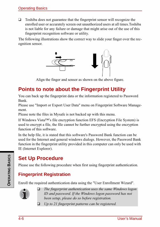
Operating BasicsO
PERA
TING
BAS
ICS
❑ Toshiba does not guarantee that the fingerprint sensor will recognize the enrolled user or accurately screen out unauthorized users at all times.Toshiba is not liable for any failure or damage that might arise out of the use of this fingerprint recognition software or utility.
The following illustrations show the correct way to slide your finger over the rec-ognition sensor.
Align the finger and sensor as shown on the above figure.
Points to note about the Fingerprint UtilityYou can back up the fingerprint data or the information registered to Password Bank.Please use "Import or Export User Data" menu on Fingerprint Software Manage-ment.Please note the files in Mysafe is not backed up with this menu.If Windows Vista™’s file encryption function EFS (Encryption File System) is used to encrypt a file, the file cannot be further encrypted using the encryption function of this software.In the help file, it is stated that this software's Password Bank function can be used for the Internet and general windows dialogs. However, the Password Bank function in the fingerprint utility provided in this computer can only be used with IE (Internet Explorer).
Set Up ProcedurePlease use the following procedure when first using fingerprint authentication.
Fingerprint Registration
Enroll the required authentication data using the "User Enrollment Wizard".❑ The fingerprint authentication uses the same Windows logon
ID and password. If the Windows logon password has not been setup, please do so before registration.
❑ Up to 21 fingerprint patterns can be registered.
4-6 User’s Manual
Operating BasicsO
PERATING BASICS
1. Click Start, Point to All Programs, point to Protector Suite QL and click User Enrollment.
2. The User's Password screen is displayed. Ensure the same Windows logon username is displayed before entering a password into the Enter your Password field. Click Next.
3. Click Next.4. The Hints for fingerprint enrollment screen is displayed.
Confirm the message and that there is a checkmark in Run interactive tutorial, and click Next.
5. The Correct swipe Procedure screen is displayed. Confirm the message and click Next.
6. The Scanning Practice screen is displayed.You can practice swiping your finger. When you have finished practicing swiping your finger, click Next.
7. The User’s Fingers screen is displayed. Based on the illustration, select the finger to be recognized, and then click Next.
8. The Capture Fingerprint screen is displayed. Follow the onscreen instructions and use the same finger you have selected under Choose Fin-ger to swipe three times to allow the sensor to read the fingerprint. The fin-gerprint will be shown in green if properly read, or in red if the reading is abnormal.
9. In case of finger injury or authentication failure, it is recommended that another fingerprint also be enrolled. The following message will be dis-played: "It is recommended that you enroll at least two fingers. Would you like to enroll another finger now?" Click Yes and repeat steps 7, 8 and 9 with another finger. If any of the previously enrolled fingerprints is selected again, the latest information will be enrolled and previous information over-written.
10. The Advanced Security screen is displayed.Select whether to enable the security function, and click Next.
11. The Finalization screen is displayed. Click Finish. This completes the fingerprint registration process.
You can also start User Enrollment Wizard using the following method.❑ Click the icon in the Task Bar.❑ Swipe your finger across the Fingerprint Sensor.
User’s Manual 4-7
Operating BasicsO
PERA
TING
BAS
ICS
Windows Logon via Fingerprint AuthenticationIn place of the usual Windows logon by ID and password, fingerprint authentica-tion also allows logon to Windows. This is useful especially when many users are using the PCs, as user selection can be skipped.
Fingerprint Authentication Procedure1. Start up the computer.2. The Logon Authorization screen is displayed. Choose any of the
enrolled fingers and swipe the fingerprint on the sensor. If authentication is successful, the user will be logged on to Windows.
If the fingerprint authentication fails, please logon using the Windows logon password.Please logon using the Windows logon password if the fingerprint authentication failed for three consecutive tries. To logon using the Windows logon password, enter the Windows logon password at the "Welcome" screen as normal.A warning message will be displayed when authentication is abnormal or authentication is not successful within a fixed duration.
4-8 User’s Manual
Operating BasicsO
PERATING BASICS
Fingerprint System Boot Authentication
General The fingerprint authentication system can be used to replace the keyboardbased User Password authentication system when booting up. If you do not want to use the fingerprint authentication system for password authentication when booting up, but prefer to use the keyboard-based system instead, press the BACK SPACE key when the Fingerprint System Bootjuhu Authentication screen is displayed. This will switch the password input screen to the keyboard-based one.
How to Enable Fingerprint System Boot Authentication SettingsIt is necessary to first enroll your fingerprint with the Protector Suite QL applica-tion prior to enabling and configuring the Fingerprint Power-on Security System.Check that your fingerprint is enrolled before configuring the settings. See Man-ual for Fingerprint Registration/Enrollment instructions.
1. Swipe your finger across the Fingerprint Sensor.2. MENU appears in the lower right corner of the screen. Swipe your finger
overtop of the Fingerprint Sensor, and select Control Center from the MENU items.
3. The Fingerprint Software Management screen is displayed to select settings → Power-on Security.
❑ It is necessary to register the User Password before using the Fingerprint Power-on Security and its extended function, the Fingerprint Single Sign-On Feature. Please use TOSHIBA HW Setup to register the User Password.
❑ If you fail fingerprint authentication more than five times, you must enter the User Password or Supervisor Password manually to start the computer.
❑ When swiping, please do it slowly and at a constant speed. If this does not improve the authentication rate, please adjust the speed.
❑ If there are any changes in the environment or settings related to authorization, you will be required to provide authorization information such as a User Password and HDD password.
User’s Manual 4-9
Operating BasicsO
PERA
TING
BAS
ICS
4. Power-on Security screen is displayed. Place a checkmark in Replace the power-on and hard drive passwords with the fingerprint reader and click OK.
The modified configuration for Fingerprint Power-on Security becomes effective the next time the system is booted up.
Fingerprint Single Sign-On Feature
GeneralThis is a feature that allows the user to complete the authentication for both the User Password (and optionally, the HDD user and Supervisor passwords) and logging on to Windows using only one fingerprint authentication when booting up. It is necessary to register the User Password and Windows Logon password before using the Fingerprint Power-on Security and this Fingerprint Single Sign On Feature. Please use TOSHIBA HW Setup to register your User Password. If Windows Logon is not the default for your system, see Manual to register your Windows Logon password. Only one fingerprint authentication is required to replace the User Password (and, if selected, the HDD user and Supervisor passwords) and Windows Logon password.
How to Enable Fingerprint Single Sign-On FeatureIt is necessary to first enroll your fingerprint with the Protector Suite QL applica-tion prior to enabling and configuring the How to Enable Fingerprint Single Sign-On Feature. Check that the fingerprint is enrolled before configuring the settings. See Manual for Fingerprint Registration/Enrollment instructions.
1. Swipe your finger across the Fingerprint Sensor.2. MENU appears in the lower right corner of the screen. Swipe your finger
overtop of the Fingerprint Sensor, and select Control Center from the MENU items.
3. Click settings and click system settings.4. The Protector Suite Settings screen is displayed. Place a checkmark in
Allow power-on security single sign-on within Enable logon sup-port and click OK.The modified configuration for the Fingerprint Single Sign-On Feature becomes effective the next time the system is booted up.
4-10 User’s Manual
Operating BasicsO
PERATING BASICS
Fingerprint utility limitationsTOSHIBA does not guarantee that the Fingerprint utility technology will be completely secure or error-free. TOSHIBA does not guarantee that the Finger-print utility will accurately screen out unauthorized users at all times. TOSHIBA is not liable for any failure or damage that might arise out of the use of the finger-print software or utility.
How to Swipe the FingerUsing the following steps when swiping fingers for fingerprint registration or authentication will help to minimize authentication failures:1. Align the first joint of the finger to the center of the sensor. Lightly touch
the sensor and swipe finger levelly towards you.While lightly touching the sensor, swipe the finger towards you until thesensor surface becomes visible.Ensure the center of the fingerprint is on the sensor when swiping the finger.
❑ Avoid swiping with the finger stiff or pressed-on too hardFingerprint reading may fail if the center of the fingerprint is not touching on the sensor, or when finger is swiped while pressing hard. Make sure that the center of the fingerprint is touching the sensor before swiping.
❑ Confirm the center of the fingerprint whirl before swipingThe thumb’s fingerprint has a bigger whirl, which is prone to misalignment and distortions. This will cause difficulty in registration and a drop in the authentication success rate. Always confirm the center of the fingerprint whirl so that it is swiped along the centerline of the sensor.
❑ When fingerprint reading is not successfulThere is a possibility of authentication failures if the finger is swiped too quickly or too slowly. Follow the onscreen instructions to adjust the speed of the swipe.
User’s Manual 4-11
Operating BasicsO
PERA
TING
BAS
ICS
Using optical disc drivesThe text and illustrations in this section refer primarily to the optical disc drive. However, operation is the same for all other optical disc drives. The full-size drive provides high-performance execution of CD/DVD/HD DVD ROM-based programs. You can run either 12 cm (4.72") or 8 cm (3.15") CD/DVD/HD DVDs without an adaptor. An ATAPI interface controller is used for CD/DVD/HD DVD-ROM operation. When the computer is accessing a CD/DVD/HD DVD-ROM, an indicator on the drive glows.
If you have a CD-RW/DVD-ROM drive, refer also to the Writing CDs on CD-RW/DVD-ROM drive section for precautions on writing to CDs.If you have a DVD Super Multi drive or a HD DVD-ROM drive, refer also to the Writing CD/DVDs on DVD Super Multi drive section for precautions on writing to CDs/DVDs.If you have a HD DVD-R drive, refer also to the Writing CD/DVD/HD DVDs on HD DVD-ROM drives section for precautions on writing to CDs/DVDs/HD DVDs.
❑ Use the TOSHIBA DVD Video Player application to view DVD-Video discs.(CD-RW/DVD-ROM drive model or DVD Super Multi drive model)
❑ Use the TOSHIBA HD DVD Video Player application to view DVD-Video discs or HD DVD-Video discs.(HD DVD-ROM model or HD DVD-R drive model)
4-12 User’s Manual
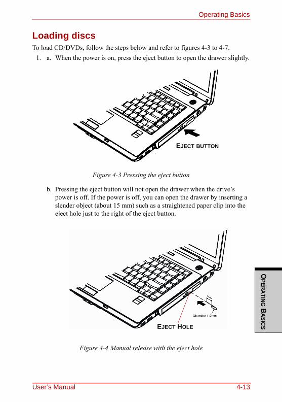
Operating BasicsO
PERATING BASICS
Loading discsTo load CD/DVDs, follow the steps below and refer to figures 4-3 to 4-7.
1. a. When the power is on, press the eject button to open the drawer slightly.
Figure 4-3 Pressing the eject button
b. Pressing the eject button will not open the drawer when the drive’s power is off. If the power is off, you can open the drawer by inserting a slender object (about 15 mm) such as a straightened paper clip into the eject hole just to the right of the eject button.
Figure 4-4 Manual release with the eject hole
EJECT BUTTON
EJECT HOLE
User’s Manual 4-13
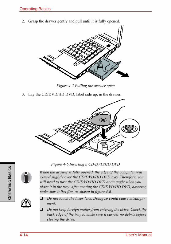
Operating BasicsO
PERA
TING
BAS
ICS
2. Grasp the drawer gently and pull until it is fully opened.
Figure 4-5 Pulling the drawer open
3. Lay the CD/DVD/HD DVD, label side up, in the drawer.
Figure 4-6 Inserting a CD/DVD/HD DVD
When the drawer is fully opened, the edge of the computer will extend slightly over the CD/DVD/HD DVD tray. Therefore, you will need to turn the CD/DVD/HD DVD at an angle when you place it in the tray. After seating the CD/DVD/HD DVD, however, make sure it lies flat, as shown in figure 4-6.❑ Do not touch the laser lens. Doing so could cause misalign-
ment.❑ Do not keep foreign matter from entering the drive. Check the
back edge of the tray to make sure it carries no debris before closing the drive.
4-14 User’s Manual
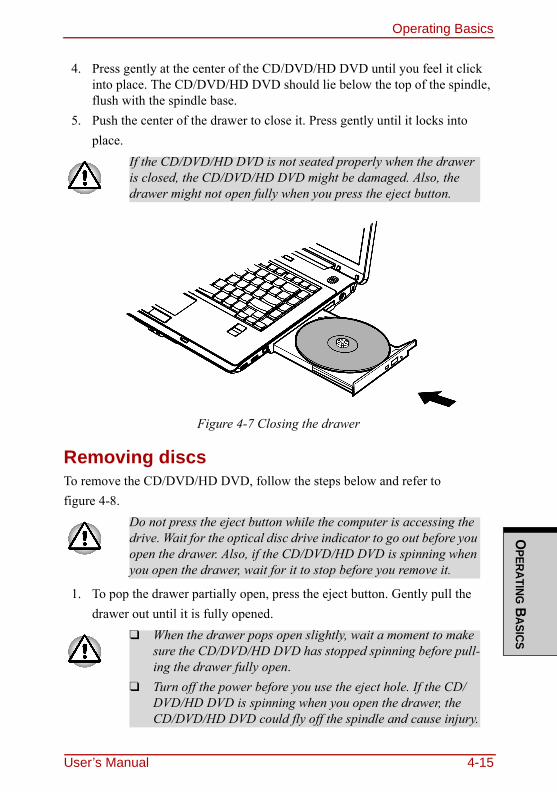
Operating BasicsO
PERATING BASICS
4. Press gently at the center of the CD/DVD/HD DVD until you feel it click into place. The CD/DVD/HD DVD should lie below the top of the spindle, flush with the spindle base.
5. Push the center of the drawer to close it. Press gently until it locks into place.
Figure 4-7 Closing the drawer
Removing discsTo remove the CD/DVD/HD DVD, follow the steps below and refer to figure 4-8.
1. To pop the drawer partially open, press the eject button. Gently pull the drawer out until it is fully opened.
If the CD/DVD/HD DVD is not seated properly when the drawer is closed, the CD/DVD/HD DVD might be damaged. Also, the drawer might not open fully when you press the eject button.
Do not press the eject button while the computer is accessing the drive. Wait for the optical disc drive indicator to go out before you open the drawer. Also, if the CD/DVD/HD DVD is spinning when you open the drawer, wait for it to stop before you remove it.
❑ When the drawer pops open slightly, wait a moment to make sure the CD/DVD/HD DVD has stopped spinning before pull-ing the drawer fully open.
❑ Turn off the power before you use the eject hole. If the CD/DVD/HD DVD is spinning when you open the drawer, the CD/DVD/HD DVD could fly off the spindle and cause injury.
User’s Manual 4-15
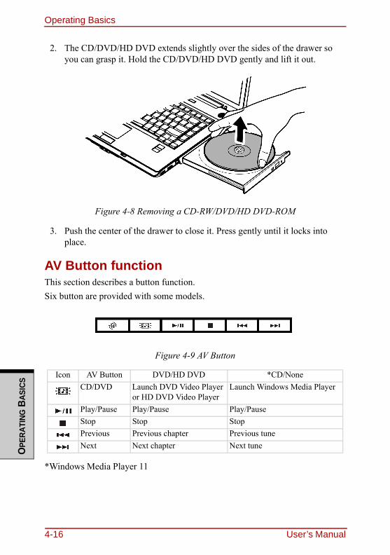
Operating BasicsO
PERA
TING
BAS
ICS
2. The CD/DVD/HD DVD extends slightly over the sides of the drawer so you can grasp it. Hold the CD/DVD/HD DVD gently and lift it out.
Figure 4-8 Removing a CD-RW/DVD/HD DVD-ROM
3. Push the center of the drawer to close it. Press gently until it locks into place.
AV Button functionThis section describes a button function.Six button are provided with some models.
Figure 4-9 AV Button
*Windows Media Player 11
Icon AV Button DVD/HD DVD *CD/NoneCD/DVD Launch DVD Video Player
or HD DVD Video PlayerLaunch Windows Media Player
Play/Pause Play/Pause Play/PauseStop Stop StopPrevious Previous chapter Previous tuneNext Next chapter Next tune
4-16 User’s Manual
Operating BasicsO
PERATING BASICS
Using TOSHIBA HD DVD PLAYER to enjoy HD DVDs
HD DVD Playback RestrictionsHD DVD-ROM drive and HD DVD-R drive model allow users to enjoy the strong visuals of HD DVDVideo."TOSHIBA HD DVD PLAYER" software is provided for playback of HD DVD-Video.
Notes on use
HD DVD Playback❑ HD DVD is a new standard which makes use of new technologies. As such,
there is a possibility of problems occurring related to connection, compati-bility or operation with some discs and other digital devices. The HD DVD-ROM logo sign fies that this drive complies with the HD DVD physical standard, and does not signify compliance with the HD DVD Video stan-dard. This device might not support advanced features of the HD DVD Video standard as defined by the DVD Forum, including picture-in-picture and network download features. Screen movement may not be smooth, and performance may be lowered with some HD DVD content.
❑ This device supports AACS (Advanced Access Content System) nextgener-ation copy pr tection technology. Renewal of the AACS key integrated into this device is required for uninterrupted enjoyment of HD DVD. An Internet connection is required when renewing the key.
❑ Because HD DVD playback operates according to programs built-into the content, operation methods, operation screens, sound effects, icons and other features may vary from disc to disc. For more information on these items refer to instructions included with content or contact the content manufactur-ers directly.
User’s Manual 4-17
Operating BasicsO
PERA
TING
BAS
ICS
Notes on playing HD DVD Video discs
HD DVD Video discs❑ Please use "TOSHIBA HD DVD PLAYER" for HD DVD Video playback.
"Windows Media Player" and other commercially available software cannot be used for HD DVD Video playback.
❑ HD DVD Video playback may take several moments to begin.❑ When playing an HD DVD (Twin format disc), run it from the "TOSHIBA
HD DVD Launcher Menu". Only the HD DVD Layer of an HD DVD (Twin format disc) can be played in the "TOSHIBA HD DVD PLAYER".
When Using❑ Frame dropping, audio skipping or out of synch audio and video may occur
during playback of some HD DVD Video titles.❑ Close all other applications when using the “TOSHIBA HD DVD
PLAYER”. Do not open any other applications or carry out any other opera-tions during HD DVD Video playback. Playback may stop or not function properly in some situations.
❑ If windows or icons of memory-resident programs flicker during playback, maximize the "TOSHIBA HD DVD PLAYER" window.
❑ Do not playback HD DVD discs Video while watching or recording televi-sion programs using other applications. Doing so may cause HD DVD Video playback or television program recording errors. In addition, if pre-scheduled recording starts during HD DVD Video playback it may cause HD DVD Video playback or television program recording errors. Please view HD DVD Video during times when there is no recording pre-sched-uled.
❑ The resume function cannot be used with some discs on the "TOSHIBA HD DVD PLAYER".
❑ Make sure to connect the computer's AC adaptor when using the "TOSHIBA HD DVD PLAYER". Power-saving features may interfere with smooth playback.
❑ Set the "Power option" profile to "High Performance" when using the "TOSHIBA HD DVD PLAYER".
❑ Screen savers will not display while playing a movie in the "TOSHIBA HD DVD PLAYER". The computer will also not go into Sleep Mode, Hiberna-tion Mode or shutdown while using "TOSHIBA HD DVD PLAYER".
4-18 User’s Manual
Operating BasicsO
PERATING BASICS
❑ Do not configure the Display automatic power off function to run while the "TOSHIBA HD DVD PLAYER" is running.
❑ The Windows Aero function is disabled while the "TOSHIBA HD DVD PLAYER" is running.
Display Devices & Audio❑ "TOSHIBA HD DVD PLAYER" will only run when "Colors" is set to
"Highest (32 bit)". The "Colors" setting can be adjusted on the "Monitor" tab in the "Display Settings". To open the Display Settings, click Start → Con-trol Panel → Appearance and Personalization → Personalization → Display Settings.
❑ If the HD DVD Video image is not displayed on an external display or tele-vision, stop the "TOSHIBA HD DVD PLAYER", and change the screen res-olution in "Resolution" on the "Monitor" tab in the "Display Settings". However, video cannot be output to some external displays and televisions due to output or playback conditions.
❑ An HDCP compatible HDMI input is required on external displays or televi-sions to view video being played in the "TOSHIBA HD DVD PLAYER" on an external display or television.
❑ When viewing on an external display or television, use an HDMI cable to connect the external device to the HDMI out port and change the display device before playing. The display device cannot be changed during play-back.
❑ HD DVD Video can only be displayed on the computer's display panel or televisions connected to the computer's HDMI out port. HD DVD Video cannot be displayed on televisions connected to the S-Video output connec-tor or external displays connected to the RGB connector. In addition, HD DVD Video cannot be displayed simultaneously (in clone or Dualview modes) on the computer's display panel and an external display or television.
❑ Do not change the screen resolution while running the "TOSHIBA HD DVD PLAYER".
❑ Audio output through the S/PDIF cannot be recorded when playing an HD DVD in the "TOSHIBA HD DVD PLAYER".
❑ Audio data of more than 48 kHz/16 bit will be down sampled to 48 kHz/16 bit.
User’s Manual 4-19
Operating BasicsO
PERA
TING
BAS
ICS
TOSHIBA HD DVD PLAYER❑ "TOSHIBA HD DVD PLAYER" software is supported for playback of HD
DVD Video, DVD-Video and DVD-VR.❑ The "TOSHIBA HD DVD PLAYER" does not have a parental control func-
tion.❑ In order to protect copyrights, the Windows Print Screen function is disabled
when "TOSHIBA HD DVD PLAYER" is running.(Print Screen functions are disabled even when running other applications besides "TOSHIBA HD DVD PLAYER" and when "TOSHIBA HD DVD PLAYER" is minimized.) Please close the "TOSHIBA HD DVD PLAYER" to use the Print Screen function.
❑ Carry out the installation/uninstallation of the "TOSHIBA HD DVD PLAYER" under a user account with administrator rights.
❑ Do not change Windows Users while "TOSHIBA HD DVD PLAYER" is running.
❑ Some HD DVD Video disc titles may return to the title before the playback time (playback position) displayed in the control window reaches the end time.
❑ For some HD DVD Video discs, using the control window to change the audio track will also change the subtitle track.
❑ Periodic updates will be necessary to continue using the "TOSHIBA HD DVD PLAYER".
Using TOSHIBA HD DVD PLAYER
Starting TOSHIBA HD DVD PLAYER1. Use the following procedure to start "TOSHIBA HD DVD PLAYER".
Insert an HD DVD-Video in the HD DVD drive while Windows Vista™ is running. When an HD DVD-Video disc and an HD DVD (Twin format disc) are set in the HD DVD drive, the following application selection screen may appear.
4-20 User’s Manual
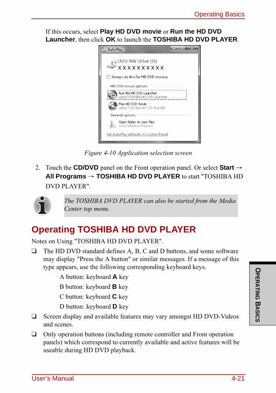
Operating BasicsO
PERATING BASICS
If this occurs, select Play HD DVD movie or Run the HD DVD Launcher, then click OK to launch the TOSHIBA HD DVD PLAYER.
Figure 4-10 Application selection screen
2. Touch the CD/DVD panel on the Front operation panel. Or select Start → All Programs → TOSHIBA HD DVD PLAYER to start "TOSHIBA HD DVD PLAYER".
Operating TOSHIBA HD DVD PLAYERNotes on Using "TOSHIBA HD DVD PLAYER".❑ The HD DVD standard defines A, B, C and D buttons, and some software
may display "Press the A button" or similar messages. If a message of this type appears, use the following corresponding keyboard keys.
A button: keyboard A keyB button: keyboard B keyC button: keyboard C keyD button: keyboard D key
❑ Screen display and available features may vary amongst HD DVD-Videos and scenes.
❑ Only operation buttons (including remote controller and Front operation panels) which correspond to currently available and active features will be useable during HD DVD playback.
The TOSHIBA DVD PLAYER can also be started from the Media Center top menu.
User’s Manual 4-21
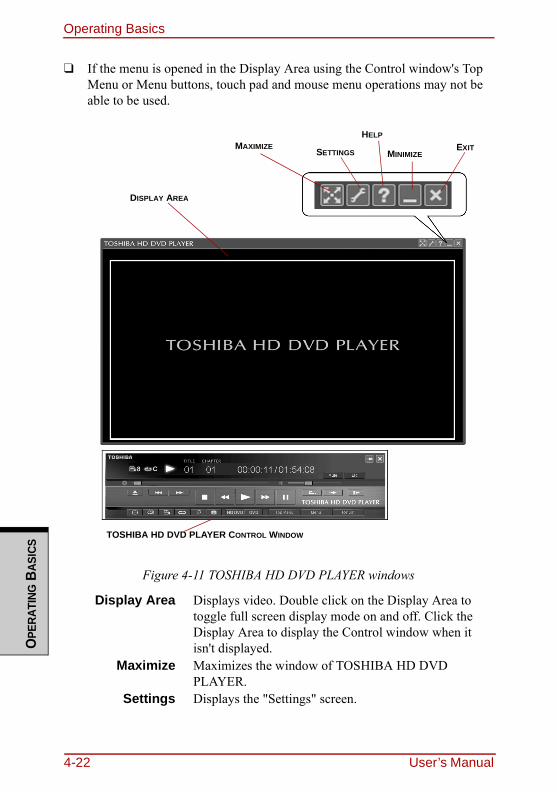
Operating BasicsO
PERA
TING
BAS
ICS
❑ If the menu is opened in the Display Area using the Control window's Top Menu or Menu buttons, touch pad and mouse menu operations may not be able to be used.
Figure 4-11 TOSHIBA HD DVD PLAYER windows
Display Area Displays video. Double click on the Display Area to toggle full screen display mode on and off. Click the Display Area to display the Control window when it isn't displayed.
Maximize Maximizes the window of TOSHIBA HD DVD PLAYER.
Settings Displays the "Settings" screen.
EXITMINIMIZE
HELPMAXIMIZE SETTINGS
DISPLAY AREA
TOSHIBA HD DVD PLAYER CONTROL WINDOW
4-22 User’s Manual
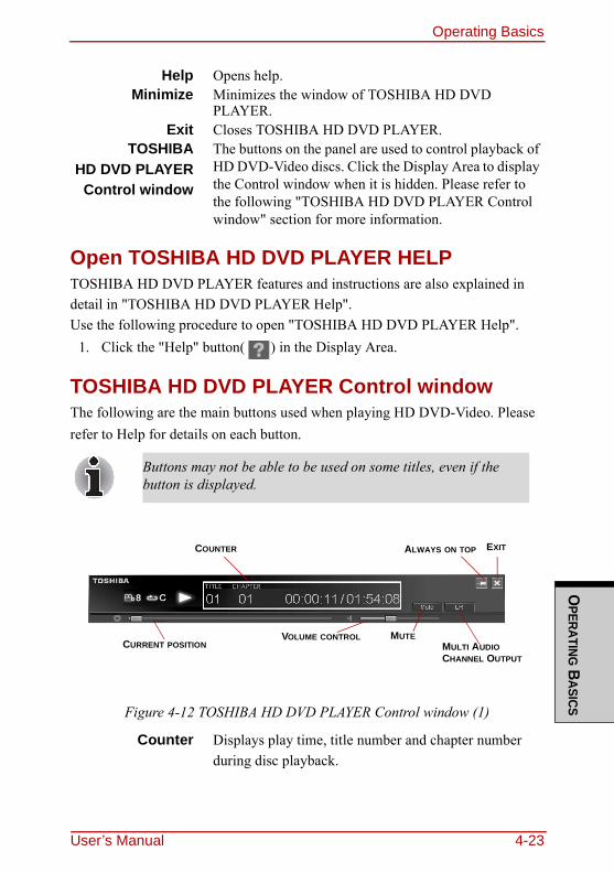
Operating BasicsO
PERATING BASICS
Open TOSHIBA HD DVD PLAYER HELPTOSHIBA HD DVD PLAYER features and instructions are also explained in detail in "TOSHIBA HD DVD PLAYER Help".Use the following procedure to open "TOSHIBA HD DVD PLAYER Help".
1. Click the "Help" button( ) in the Display Area.
TOSHIBA HD DVD PLAYER Control windowThe following are the main buttons used when playing HD DVD-Video. Please refer to Help for details on each button.
Figure 4-12 TOSHIBA HD DVD PLAYER Control window (1)
Help Opens help.Minimize Minimizes the window of TOSHIBA HD DVD
PLAYER.Exit Closes TOSHIBA HD DVD PLAYER.
TOSHIBAHD DVD PLAYER
Control window
The buttons on the panel are used to control playback of HD DVD-Video discs. Click the Display Area to display the Control window when it is hidden. Please refer to the following "TOSHIBA HD DVD PLAYER Control window" section for more information.
Buttons may not be able to be used on some titles, even if the button is displayed.
Counter Displays play time, title number and chapter number during disc playback.
EXITALWAYS ON TOPCOUNTER
MULTI AUDIO CHANNEL OUTPUT
MUTEVOLUME CONTROLCURRENT POSITION
User’s Manual 4-23
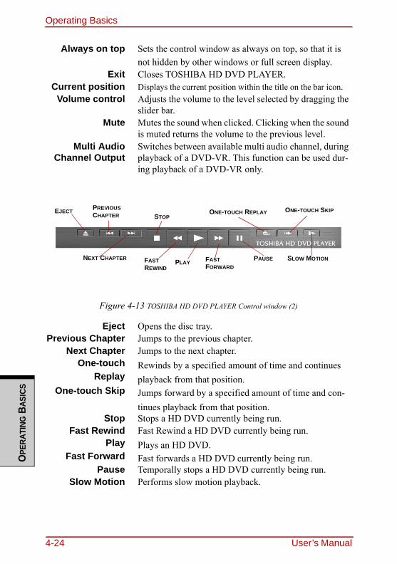
Operating BasicsO
PERA
TING
BAS
ICS
Figure 4-13 TOSHIBA HD DVD PLAYER Control window (2)
Always on top Sets the control window as always on top, so that it is not hidden by other windows or full screen display.
Exit Closes TOSHIBA HD DVD PLAYER.Current position Displays the current position within the title on the bar icon.
Volume control Adjusts the volume to the level selected by dragging the slider bar.
Mute Mutes the sound when clicked. Clicking when the sound is muted returns the volume to the previous level.
Multi AudioChannel Output
Switches between available multi audio channel, during playback of a DVD-VR. This function can be used dur-ing playback of a DVD-VR only.
Eject Opens the disc tray.Previous Chapter Jumps to the previous chapter.
Next Chapter Jumps to the next chapter.One-touch
ReplayRewinds by a specified amount of time and continues playback from that position.
One-touch Skip Jumps forward by a specified amount of time and con-tinues playback from that position.
Stop Stops a HD DVD currently being run.Fast Rewind Fast Rewind a HD DVD currently being run.
Play Plays an HD DVD.Fast Forward Fast forwards a HD DVD currently being run.
Pause Temporally stops a HD DVD currently being run.Slow Motion Performs slow motion playback.
SLOW MOTION
ONE-TOUCH SKIPONE-TOUCH REPLAY
PAUSEFAST FORWARD
PLAYFAST REWIND
STOP
PREVIOUS CHAPTER
NEXT CHAPTER
EJECT
4-24 User’s Manual
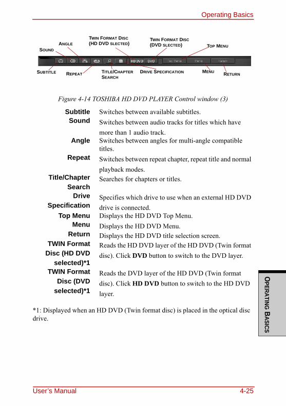
Operating BasicsO
PERATING BASICS
Figure 4-14 TOSHIBA HD DVD PLAYER Control window (3)
*1: Displayed when an HD DVD (Twin format disc) is placed in the optical disc drive.
Subtitle Switches between available subtitles.Sound Switches between audio tracks for titles which have
more than 1 audio track.Angle Switches between angles for multi-angle compatible
titles.Repeat Switches between repeat chapter, repeat title and normal
playback modes.Title/Chapter
SearchSearches for chapters or titles.
DriveSpecification
Specifies which drive to use when an external HD DVD drive is connected.
Top Menu Displays the HD DVD Top Menu.Menu Displays the HD DVD Menu.
Return Displays the HD DVD title selection screen.TWIN Format
Disc (HD DVDselected)*1
Reads the HD DVD layer of the HD DVD (Twin format disc). Click DVD button to switch to the DVD layer.
TWIN FormatDisc (DVD
selected)*1
Reads the DVD layer of the HD DVD (Twin format disc). Click HD DVD button to switch to the HD DVD layer.
RETURNMENU
TOP MENUTWIN FORMAT DISC(DVD SLECTED)
TWIN FORMAT DISC(HD DVD SLECTED)
DRIVE SPECIFICATIONTITLE/CHAPTER SEARCH
REPEAT
ANGLESOUND
SUBTITLE
User’s Manual 4-25
Operating BasicsO
PERA
TING
BAS
ICS
Using the Computer in place of an HD DVD PlayerVideos played using "TOSHIBA HD DVD PLAYER" included with the com-puter can be displayed on a television equipped with an HDMI input port.
Before ConnectingPlease refer to the television's user manual as well as this chapter when connect-ing the computer to a television. ❑ Televisions Which Can Be Connected to the Computer
Televisions which are equipped with an HDMI input port can be connected to the computer. Please use a commercially available HDMI cable to connect the television and computer. Not all televisions equipped with an HDMI input port have been tested for compatibility with this product. As such, Toshiba cannot guarantee that HD DVD-Video content can be displayed on all televisions equipped with an HDMI input port. HD DVD Video content may not display properly on some televisions.
HD DVD-Video can only be displayed on the computer's display panel or on a television connected to the HDMI out port. HD DVD-Video cannot be displayed on televisions connected to the S-Video out port or external displays connected to the RGB connector.
4-26 User’s Manual
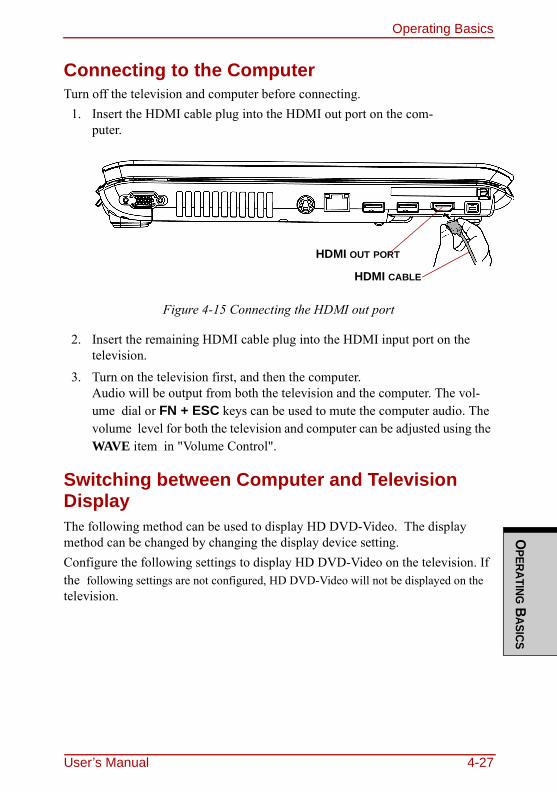
Operating BasicsO
PERATING BASICS
Connecting to the ComputerTurn off the television and computer before connecting.
1. Insert the HDMI cable plug into the HDMI out port on the com-puter.
Figure 4-15 Connecting the HDMI out port
2. Insert the remaining HDMI cable plug into the HDMI input port on the television.
3. Turn on the television first, and then the computer. Audio will be output from both the television and the computer. The vol-ume dial or FN + ESC keys can be used to mute the computer audio. The volume level for both the television and computer can be adjusted using the WAVE item in "Volume Control".
Switching between Computer and Television DisplayThe following method can be used to display HD DVD-Video. The display method can be changed by changing the display device setting.Configure the following settings to display HD DVD-Video on the television. If the following settings are not configured, HD DVD-Video will not be displayed on the television.
HDMI OUT PORT
HDMI CABLE
User’s Manual 4-27
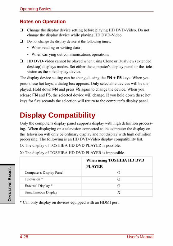
Operating BasicsO
PERA
TING
BAS
ICS
Notes on Operation❑ Change the display device setting before playing HD DVD-Video. Do not
change the display device while playing HD DVD-Video.❑ Do not change the display device at the following times.
• When reading or writing data.• When carrying out communications operations.
❑ HD DVD-Video cannot be played when using Clone or Dualview (extended desktop) displays modes. Set either the computer's display panel or the tele-vision as the sole display device.
The display device setting can be changed using the FN + F5 keys. When you press these hot keys, a dialog box appears. Only selectable devices will be dis-played. Hold down FN and press F5 again to change the device. When you release FN and F5, the selected device will change. If you hold down these hot keys for five seconds the selection will return to the computer’s display panel.
Display CompatibilityOnly the computer's display panel supports display with high definition process-ing. When displaying on a television connected to the computer the display on the television will only be ordinary display and not display with high definition processing. The following is an HD DVD-Video display compatibility list.O: The display of TOSHIBA HD DVD PLAYER is possible.
X: The display of TOSHIBA HD DVD PLAYER is impossible.
* Can only display on devices equipped with an HDMI port.
When using TOSHIBA HD DVD
PLAYERComputer's Display Panel OTelevision * OExternal Display * OSimultaneous Display X
4-28 User’s Manual
Operating BasicsO
PERATING BASICS
Writing CDs on CD-RW/DVD-ROM driveYou can use the CD-RW/DVD-ROM drive to write data to either CD-R or CD-RW discs. The following applications for writing are supplied: TOSHIBA Disc Creator.
Important message (CD-RW/DVD-ROM drive)Before you write or rewrite to CD-R/RW disc, read and follow all setup and operating instructions in this section. If you fail to do so, the CD-RW/DVD-ROM drive may not function properly, and you may fail to write or rewrite, lose data or incur other damage.
Before writing or rewritingPlease observe the following points when you write or rewrite the data.◆ We recommend the following manufacturers of CD-R and CD-RW media.
Media quality can affect write or rewrite success rates.
TOSHIBA has confirmed the operation of CD-R and CD-RW media of the man-ufacturers above. Operation of other media cannot be guaranteed.◆ CD-RW can generally be rewritten about 1,000 times. However, the actual
number of rewrites is affected by the quality of the media and the way it is used.
◆ Be sure to connect the AC adaptor when you write or rewrite.◆ Be sure to close all other software programs except the writing software.
CD-R discs can be written to only once. CD-RW discs can be rewritten many times.
CD-R: TAIYO YUDEN CO., LTD.Mitsui Chemicals Inc.MITSUBISHI KAGAKU MEDIA CO., LTDRicoh Co., Ltd.Hitachi Maxell Ltd.
CD-RW: MITSUBISHI KAGAKU MEDIA CO., LTDRicoh Co., Ltd.
User’s Manual 4-29
Operating BasicsO
PERA
TING
BAS
ICS
◆ Do not run software such as a screen saver which can put a heavy load on the CPU.
◆ Operate the computer at full power. Do not use power-saving features.◆ Do not write while virus check software is running. Wait for it to finish, then
disable virus detection programs including any software that checks files automatically in the background.
◆ Do not use hard disk utilities, including those intended to enhance HDD access speed. They may cause unstable operation and damage data.
◆ Write from the computer’s HDD to the CD. Do not try to write from shared devices such as a LAN server or any other network device.
◆ Writing with software other than TOSHIBA Disc Creator has not been con-firmed. Therefore, operation with other software cannot be guaranteed.
When writing or rewritingNote the following when you write or rewrite a CD-R or CD-RW.◆ Always copy data from the HDD to the CD. Do not use cut-and-paste. The
original data will be lost if there is a write error.◆ Do not perform any of the following actions:
◆ Change users in the Windows Vista™ operating system.◆ Operate the computer for any other function, including use of a mouse
or Touch Pad, closing/opening the LCD panel.◆ Start a communication application such as a modem.◆ Apply impact or vibration to the PC.◆ Install, remove or connect external devices, including the following:
Express Card, USB devices, external display, i.LINK devices, optical digital devices.
◆ Open the optical disc drive.◆ Do not use shut down/log off and sleep/hibernation while writing or rewrit-
ing.◆ If the media is poor in quality, dirty or damaged, writing or rewriting errors
may occur.◆ Set the computer on a level surface and avoid places subject to vibration
such as airplanes, trains, or cars. Do not use an unstable surface such as a stand.
◆ Keep mobile phones and other wireless communication devices away from the computer.
4-30 User’s Manual
Operating BasicsO
PERATING BASICS
Disclaimer (CD-RW/DVD-ROM drive)TOSHIBA does not bear responsibility for the following:◆ Damage to any CD-R/RW disc that may be caused by writing or rewriting
with this product.◆ Any change or loss of the recorded contents of CD-R/RW disc that may be
caused by writing or rewriting with this product, or for any business profit loss or business interruption that may be caused by the change or loss of the recorded contents.
◆ Damage that may be caused by using third party equipment or software. Given the technological limitations of current optical disc writing drives, you may experience unexpected writing or rewriting errors due to disc qual-ity or problems with hardware devices. Also, it is a good idea to make two or more copies of important data, in case of undesired change or loss of the recorded contents.
Writing CD/DVDs on DVD Super Multi (+-R DL) driveYou can use the DVD Super Multi (+-R DL ) drive to write data to either CD-R/RW or DVD-R/-RW/+R/+RW/-RAM/+R DL/-R DL discs. The following appli-cations for writing are supplied: TOSHIBA Disc Creator. Ulead DVD Movie Factory® for TOSHIBA, which is a product of Ulead Systems, Inc.
Important message (DVD Super Multi (+-R DL) drive)Before you write or rewrite to CD-R/RW or DVD-R/-RW/+R/+RW/-RAM/+R DL/-R DL disc, read and follow all setup and operating instructions in this sec-tion.If you fail to do so, the DVD Super Multi (+-R DL) drive may not function prop-erly, and you may fail to write or rewrite, lose data or incur other damage.
Before writing or rewriting◆ Based on TOSHIBA’s limited compatibility testing, we suggest the follow-
ing manufacturers of CD-R/RW and DVD-R/+R/-RW/+RW/-RAM/+R DL/-R DL disc.
User’s Manual 4-31
Operating BasicsO
PERA
TING
BAS
ICS
◆ However, in no event does TOSHIBA guarantee the operation, quality or performance of any disc. Disc quality can affect write or rewrite success rates.
◆ If the disc is poor in quality, dirty or damaged, writing or rewriting errors may occur. Be careful to check the disc for dirt or damage before you use it.
CD-R: TAIYO YUDEN CO., LTD.MITSUBISHI KAGAKU MEDIA CO., LTDRicoh Co., Ltd.Hitachi Maxell Ltd.
CD-RW:(High-Speed,MultiSpeed)
MITSUBISHI KAGAKU MEDIA CO., LTDRicoh Co., Ltd.
CD-RW:(Ultra-Speed)
MITSUBISHI KAGAKU MEDIA CO., LTD
DVD-R DVD Specifications for Recordable Disc for GeneralVersion 2.0TAIYO YUDEN CO., LTD.Matsushita Electric Industrial Co., Ltd.
DVD+R MITSUBISHI KAGAKU MEDIA CO., LTDRicoh Co., Ltd.
DVD-RW DVD Specifications for Recordable Disc for Version 1.1VICTOR COMPANY OF JAPAN, LIMITEDMITSUBISHI KAGAKU MEDIA CO., LTD
DVD+RW MITSUBISHI KAGAKU MEDIA CO., LTDRicoh Co., Ltd.
DVD-RAM DVD Specifications for DVD-RAM Disc for Version 2.0, Version 2.1 or Version 2.2Matsushita Electric Industrial Co., Ltd.Hitachi Maxell Ltd.
DVD+R DL MITSUBISHI KAGAKU MEDIA CO., LTD.DVD-R DL MITSUBISHI KAGAKU MEDIA CO., LTD.DVD-R for
Labelflash™FUJIFILM Corporation.
DVD+R for Labelflash™
FUJIFILM Corporation.
This drive cannot use discs that allow writing of 8 speeds or more (DVD-R, DVD+R ), 6 speeds or more (DVD-RW) and 8 speeds or more (DVD+RW).
4-32 User’s Manual
Operating BasicsO
PERATING BASICS
◆ The actual number of rewrites to CD-RW, DVD-RW, DVD+RW or DVD-RAM is affected by the quality of the disc and the way it is used.
◆ There are two types of DVD-R discs: authoring and general use discs. Do not use authoring discs. Only general use discs can be written to by a com-puter drive.
◆ We can support only format 1 of DVD-R DL. Therefore you can not do the additional writing. If your data is under DVD-R(SL) capacity, we suggest to use DVD-R(SL) media.
◆ You can use DVD-RAM discs that can be removed from a cartridge and DVD-RAM discs designed without a cartridge. You cannot use a disc with a 2.6 GB single-sided capacity or 5.2 GB double-sided capacity.
◆ Other DVD-ROM drives for computers or other DVD players may not be able to read DVD-R/-R DL/-RW or DVD+R/+R DL/+RW discs.
◆ Data written to a CD-R/DVD-R/DVD+R disc cannot be deleted either in whole or in part.
◆ Data deleted (erased) from a CD-RW and DVD-RW, DVD+RW and DVD-RAM disc cannot be recovered. Check the content of the disc carefully before you delete it. If multiple drives that can write data to discs are con-nected, be careful not to delete data from the wrong drive.
◆ In writing to a DVD-R/-R DL/-RW, DVD+R/+R DL/+RW or DVD-RAM disc, some disc space is required for file management, so you may not be able to write the full capacity of the disc.
◆ Since the disc is based on the DVD standard, it will be filled with dummy data if the written data is less than about 1 GB. Even if you write only a small amount of data, it might take time to fill in the dummy data.
◆ DVD-RAM formatted by FAT32 cannot be read in Windows 2000 without DVD-RAM Driver Software.
◆ When multiple drives that can write data to discs are connected, be careful not to write to the wrong drive.
◆ Be sure to connect the universal AC adaptor before you write or rewrite.◆ Before you enter sleep/hibernation mode, be sure to finish DVD-RAM writ-
ing. Writing is finished if you can eject DVD-RAM media.◆ Be sure to close all other software programs except the writing software.◆ Do not run software such as a screen saver, which can put a heavy load on
the CPU.◆ Operate the computer in the full-power mode. Do not use power-saving fea-
tures.
User’s Manual 4-33
Operating BasicsO
PERA
TING
BAS
ICS
◆ Do not write while virus check software is running. Wait for it to finish, and then disable virus detection programs including any software that checks files automatically in the background.
◆ Do not use hard disk utilities, including those intended to enhance HDD access speed. They may cause unstable operation and data damage.
◆ Write from the computer’s HDD to the CD/DVD. Do not try to write from shared devices such as a LAN server or any other network device.
◆ Writing with software other than TOSHIBA Disc Creator is not recom-mended.
When writing or rewritingPlease observe/consider the following when you write or rewrite to a CD-R/RW, DVD-R/-R DL/-RW/-RAM or DVD+R/+R DL/+RW disc.◆ Do not perform any of the following actions:
◆ Change users in the Windows Vista™ operating system.◆ Operate the computer for any other function, including use of a mouse
or Touch Pad, closing/opening the LCD panel.◆ Start a communication application such as a modem.◆ Apply impact or vibration to the PC.◆ Install, remove or connect external devices, including the following:
Express Card, USB devices, external display, i.LINK devices, optical digital devices.
◆ Use the Audio/Video control button to reproduce music or voice.◆ Open the CD-RW/DVD-ROM or DVD Super Multi (+-R DL) drive.
◆ Do not use shut down/log off and sleep/hibernation while writing or rewrit-ing.
◆ Make sure writing or rewriting is completed before going into sleep/hiberna-tion. Writing is completed if you can open the CD-RW/DVD-ROM or DVD Super Multi (+-R DL) drive tray.
◆ Set the computer on a level surface and avoid places subject to vibration such as airplanes, trains, or cars. Do not use an unstable surface such as a stand.
◆ Keep mobile phones and other wireless communication devices away from the computer.
◆ Always copy data from the HDD to the DVD-RAM. Do not use cut-and-paste. The original data will be lost if there is a write error.
4-34 User’s Manual
Operating BasicsO
PERATING BASICS
Disclaimer (DVD Super Multi (+-R DL) drive)TOSHIBA does not bear responsibility for the following:◆ Damage to any CD-R/RW or DVD-R/-R DL/-RW/+R/+R DL/+RW/DVD-
RAM disc that may be caused by writing or rewriting with this product.◆ Any change or loss of the recorded contents of CD-R/RW or DVD-R/-R DL/
-RW/+R/+R DL/+RW/DVD-RAM disc that may be caused by writing or rewriting with this product, or for any business profit loss or business inter-ruption that may be caused by the change or loss of the recorded contents.
◆ Damage that may be caused by using third party equipment or software. Given the technological limitations of current optical disc writing drives, you may experience unexpected writing or rewriting errors due to disc qual-ity or problems with hardware devices. Also, it is a good idea to make two or more copies of important data, in case of undesired change or loss of the recorded contents.
Writing CD/DVD/HD DVDs on HD DVD-R drives
You can use the HD DVD-R drive to write data to either CD-R or CD-RW, DVD-R, DVD-R (Dual Layer), DVD-RW, DVD+R, DVD+R (Double Layer), DVD-RAM, HD DVD-R, HD DVD-R(Dual layer) discs. This computer is provided with TOSHIBA Disc Creator and Ulead® DVD MovieFactory® to allow for the writing to CD, DVD and HD DVD media.
Please refer to the included Qosmio HD DVD Guide for more information on using the HD DVD-ROM drive and HD DVD-R drives.
You should use the HD DVD playback software in order to view HD DVD Video media.
The optical drive installed on this computer cannot write multiple sessions on HD DVD-R Dual Layer disc sessions. Once a disc has been written to once, it will be finalized. Once finalized, no further writing to the disc will be possible regardless of what portion of the total disc capacity was used.
User’s Manual 4-35
Operating BasicsO
PERA
TING
BAS
ICS
For further information on TOSHIBA Disc Creator and Ulead® DVD MovieFac-tory®, please refer to each software’s online manual or online helps. Refer to HD DVD Guide for information on accessing the online manual or online help.
Important message
Before you write or rewrite to any of the media supported by the HD DVD-R drive, please read and follow all of the setup and operating instructions in this section. If you fail to do so, you may find that the HD DVD-R drive may not function properly, and you may fail to write or rewrite information successfully - this may cause you to either lose data or incur other damage to the drive or media.
Legal FootnotesTOSHIBA does not bear responsibility for the following:◆ Damage to any CD-R, CD-RW, DVD-R, DVD-R (Dual Layer), DVD-RW,
DVD+R, DVD+R (Double Layer), DVD+RW, DVD-RAM or HD DVD-R disc that may be caused by writing or rewriting with this product.
◆ Any change or loss of the recorded contents of CD-R, CD-RW, DVD-R,DVD-R (Dual Layer), DVD-RW, DVD+R, DVD+R (Double Layer),DVD+RW, DVD-RAM or HD DVD-R media that may be caused by writing or rewriting with this product, or for any business profit loss or busi-ness interruption that may be caused by the change or loss of the recorded contents.
❑ Please refer to the Writable discs, Chapter 2 for details about the types of writable CD, DVD and HD DVD discs that can be supported by this computer.
❑ Do not turn off the power to the optical disc drive while the computer is accessing it as this may cause you to lose data.
❑ CD-R/RW media cannot be accessed using the Create CD/DVD option in Media Center.
❑ To write data to CD-RI-RW media, use the TOSHIBA Disc Creator feature that is installed on your computer.
When writing information to media using an optical drive, you should always ensure that you connect the AC adaptor to a live power socket. It is possible that, if data is written while powered by the battery pack, the write process may sometimes fail due to low battery power - these instances data loss may occur.
4-36 User’s Manual
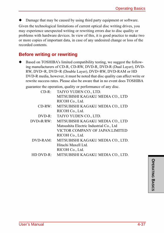
Operating BasicsO
PERATING BASICS
◆ Damage that may be caused by using third party equipment or software.Given the technological limitations of current optical disc writing drives, you may experience unexpected writing or rewriting errors due to disc quality or problems with hardware devices. In view of this, it is good practice to make two or more copies of important data, in case of any undesired change or loss of the recorded contents.
Before writing or rewriting◆ Based on TOSHIBA's limited compatibility testing, we suggest the follow-
ing manufacturers of CD-R, CD-RW, DVD-R, DVD-R (Dual Layer), DVD-RW, DVD+R, DVD+R (Double Layer), DVD+RW, DVD-RAM or HD DVD-R media, however, it must be noted that disc quality can affect write or rewrite success rates. Please also be aware that in no event does TOSHIBA guarantee the operation, quality or performance of any disc.
CD-R: TAIYO YUDEN CO., LTD.MITSUBISHI KAGAKU MEDIA CO., LTDRICOH Co., Ltd.
CD-RW: MITSUBISHI KAGAKU MEDIA CO., LTDRICOH Co., Ltd.
DVD-R: TAIYO YUDEN CO., LTD. DVD±R/RW: MITSUBISHI KAGAKU MEDIA CO., LTD
Matsushita Electric Industrial Co., LtdVICTOR COMPANY OF JAPAN.LIMITEDRICOH Co., Ltd.
DVD-RAM: MITSUBISHI KAGAKU MEDIA CO., LTD.Hitachi Maxell Ltd.RICOH Co., Ltd.
HD DVD-R: MITSUBISHI KAGAKU MEDIA CO., LTD.
User’s Manual 4-37
Operating BasicsO
PERA
TING
BAS
ICS
◆ If the disc is poor in quality, or is dirty or damaged, writing or rewriting errors may be noted - ensure that you check all discs for dirt or damage before you use them.
◆ The actual number of rewrites to CD-RW, DVD-RW, DVD+RW or DVD-RAM media will be affected by the quality of the disc itself and the way in which it is used.
◆ There are two types of DVD-R media available, authoring discs and general use discs. Do not attempt to use authoring discs as only general use discs can be written to by a computer drive.
◆ You can use both DVD-RAM discs that can be removed from a cartridge and DVD-RAM discs designed without a cartridge.
◆ You may find that other computer DVD-ROM drives or other DVD players may not be able to read DVD-R, DVD-R (Dual Layer), DVD-RW, DVD+R, DVD+R (Double Layer), DVD+RW or HD DVD-R discs.
◆ Data written to a CD-R, DVD-R, DVD-R (Dual Layer), DVD+R, DVD+R (Double Layer) or HD DVD-R discs cannot be deleted either in whole or in part.
◆ Data deleted/erased from a CD-RW, DVD-RW, DVD+RW, DVD-RAM or HD DVD-R disc cannot be recovered. You must check the content of the disc carefully before you delete it, taking care that, if multiple drives that can write data to discs are connected, you do not delete data from the wrong one.
◆ In writing to DVD-R, DVD-R (Dual Layer), DVD-RW, DVD+R, DVD+R (Double Layer), DVD+RW, DVD-RAM or HD DVD-R media, some space is required for file management, so you may not be able to write to the full capacity of the disc.
◆ Since the disc is based on the DVD standard, it might be filled with dummy data if the written data is less than about 1GB. Therefore, in these circum-
❑ This drive cannot use discs that allow writing faster than 8x speed (DVD-R and DVD+R media), 4x speed (DVD-RW and DVD+RW media), 5x speed (DVD-RAM media), 2x speed (DVD-R (Dual Layer) media) and 2.4x speed (DVD+R (Dou-ble Layer media).
❑ Some types and formats of DVD-R (Dual Layer) and DVD+R (Double Layer) discs may be unreadable.
❑ 2.6GB and 5.2GB DVD-RAM media cannot be read from or written to.
❑ DISC created in DVD-R (Dual Layer) format4 (Layer Jump Recording) cannot be read.
4-38 User’s Manual
Operating BasicsO
PERATING BASICS
stance, even if you write only a small amount of data, it might take addi-tional time to fill in the dummy data.
◆ When multiple drives that can write data to discs are connected, be sure that you do not write to or delete data from the wrong drive.
◆ Be sure to connect the AC adaptor to the computer before you write or rewrite any information.
◆ Before you enter either Sleep Mode or Hibernation Mode, take care to ensure that any DVD-RAM writing has been completed. In this instance, writing is finished if you can eject the DVD-RAM media.
◆ Be sure to close all other software programs except for the writing software itself.
◆ Do not run software such as a screen saver which can put a heavy load on the processor.
◆ Operate the computer at its full power settings - do not use any power-saving features.
◆ Do not write information while virus checking software is running, instead wait for it to finish, then disable the virus protection applications, including any software that checks files automatically in the background.
◆ Do not use any hard disk utilities, including those that are intended to enhance hard disk drive access speeds, as they may cause unstable operation and damage data.
◆ CD-RW (Ultra Speed +) media should not be used as data may be lost or damaged.
◆ You should always write from the computer's hard disk drive onto the CD/DVD/HD DVD - do not try to write from shared devices such as a server or any other network device.
◆ Writing with software other than TOSHIBA Disc Creator has not been con-firmed, therefore operation with other software applications cannot be guar-anteed.
When writing or rewritingPlease observe the following points while you write or rewrite data to CD-R, CD-RW, DVD-R, DVD-R (Dual Layer), DVD-RW, DVD+R, DVD+R (Double Layer), DVD+RW, DVD-RAM or HD DVD-R media:◆ Always copy data from the hard disk drive to the optical disc - do not use the
cut-and-paste function as the original data will be lost if there is a write error.
User’s Manual 4-39
Operating BasicsO
PERA
TING
BAS
ICS
◆ Do not perform any of the following actions:• Change users in the Windows VistaTM operating system.• Operate the computer for any other function, including such tasks as
using a mouse or Touch Pad, or closing/opening the display panel.• Start a communication application such as a modem.• Apply impact or vibration to the computer.• Install, remove or connect external devices, including such items as a SD/
SDHC memory card, ExpressCard, Memory Stick/Memory Stick Pro, xD picture card, MultiMediaCard, USB device, external monitor, i.LINK device, or an optical digital device.
• Use the audio/video control button to reproduce music or voice.• Open the optical disc drive.
◆ Do not use shut down, log off, Sleep Mode or Hibernation Mode functions while writing or rewriting.
◆ Make sure that the write/rewrite operation is completed before going into either Sleep Mode or Hibernation Mode (writing is completed if you can remove an optical disc on the HD DVD-R drive).
◆ If the media is of poor quality, or is dirty or damaged, writing or rewriting errors may occur.
◆ Set the computer on a level surface and avoid places subject tovibration such as airplanes, trains or cars. In addition, do not use the computer on an unsta-ble surface such as a stand.
◆ Keep mobile phones and other wireless communication devices away from the computer.
TOSHIBA Disc CreatorNote the following limitations when you use TOSHIBA Disc Creator:◆ DVD-Video cannot be created using TOSHIBA Disc Creator.◆ DVD-Audio cannot be created using TOSHIBA Disc Creator.◆ You cannot use TOSHIBA Disc Creator's 'Audio CD for Car or Home CD
Player' function to record music to DVD-R, DVD-R (Dual Layer),DVD-RW, DVD+R, DVD+R (Double Layer), DVD+RW or HD DVD-R media.
◆ Do not use the 'Disc Backup' function of TOSHIBA Disc Creator in order to copy DVD Video, DVD-ROM or HD DVD-R material that has copyright protection.
4-40 User’s Manual
Operating BasicsO
PERATING BASICS
◆ DVD-RAM discs cannot be backed up using the 'Disc Backup' functionof TOSHIBA Disc Creator.
◆ You cannot back up CD-ROM, CD-R or CD-RW media to DVD-R, DVD-R (Dual Layer), DVD-RW or HD DVD-R media using the 'Disc Backup' func-tion of TOSHIBA Disc Creator.
◆ You cannot back up CD-ROM, CD-R or CD-RW media to DVD+R, DVD+R (Double Layer) or DVD+RW media using the 'Disc Backup'func-tion of TOSHIBA Disc Creator.
◆ You cannot back up DVD-ROM, DVD Video, DVD-R, DVD-R (Dual Layer), DVD-RW, DVD+R, DVD+R (Double Layer), DVD+RW or HD DVD-R to CD-R or CD-RW media using the 'Disc Backup' function of TOSHIBA Disc Creator.
◆ TOSHIBA Disc Creator cannot record in packet format.◆ You might not be able to use the 'Disc Backup' function of TOSHIBA Disc
Creator to back up a DVD-R, DVD-R (Dual Layer), DVD-RW, DVD+R, DVD+R (Double Layer), DVD+RW or HD DVD-R disc that was made with other software on a different optical media recorder.
◆ If you add data to a DVD-R, DVD-R (Dual Layer), DVD+R, DVD+R (Dou-ble Layer) or HD DVD-R disc that you have already recorded to,you might not be able to read the added data under some circumstances. For example, it cannot be read under 16-bit operating systems, such as Windows 98SE and Windows Me, while in Windows NT4 you will need Service Pack 6 or later, and in Windows 2000, you will need Service Pack 2. In addition to this, some DVD-ROM and DVD-ROM / CD-R/RW drives cannot read this added data regardless of the operating system.
◆ TOSHIBA Disc Creator does not support recording to DVD-RAM discs - to achieve this you should use Windows Explorer or another similar utility.
◆ When you back up a DVD disc, be sure that the source drive supports recording to DVD-R, DVD-R (Dual Layer), DVD-RW, DVD+R, DVD+R (Double Layer) or DVD+RW media - if this is not the case then the source disc might not be backed up correctly.
◆ When you back up a DVD-R, DVD-R (Dual Layer), DVD-RW, DVD+R,DVD+R (Double Layer), DVD+RW or HD DVD-R disc, be sure to use the same type of disc.
◆ You cannot partially delete any data written to a CD-RW, DVD-RW, DVD+RW disc.
User’s Manual 4-41
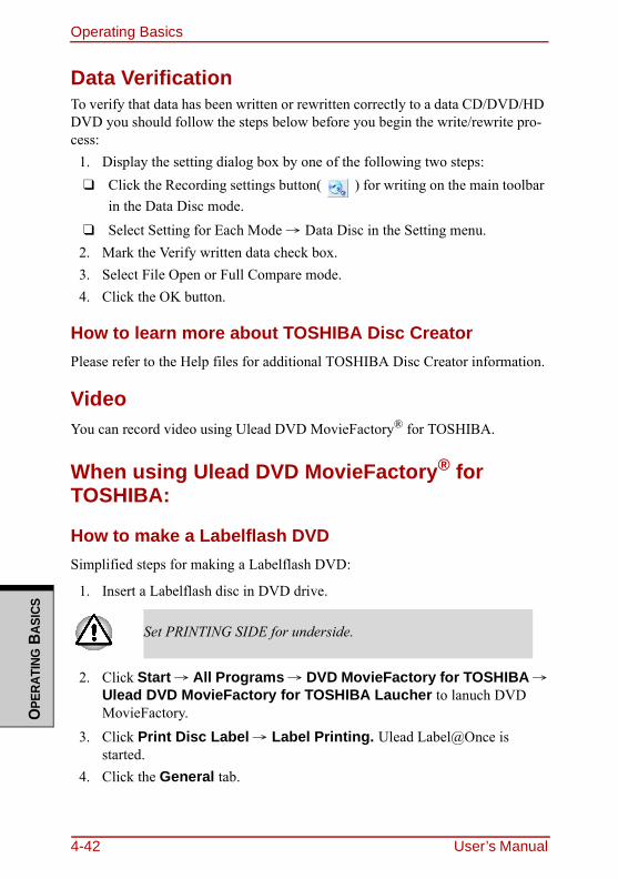
Operating BasicsO
PERA
TING
BAS
ICS
Data VerificationTo verify that data has been written or rewritten correctly to a data CD/DVD/HD DVD you should follow the steps below before you begin the write/rewrite pro-cess:
1. Display the setting dialog box by one of the following two steps: ❑ Click the Recording settings button( ) for writing on the main toolbar
in the Data Disc mode.❑ Select Setting for Each Mode → Data Disc in the Setting menu.
2. Mark the Verify written data check box.3. Select File Open or Full Compare mode.4. Click the OK button.
How to learn more about TOSHIBA Disc CreatorPlease refer to the Help files for additional TOSHIBA Disc Creator information.
VideoYou can record video using Ulead DVD MovieFactory® for TOSHIBA.
When using Ulead DVD MovieFactory® for TOSHIBA:
How to make a Labelflash DVDSimplified steps for making a Labelflash DVD:
1. Insert a Labelflash disc in DVD drive.
2. Click Start → All Programs → DVD MovieFactory for TOSHIBA →Ulead DVD MovieFactory for TOSHIBA Laucher to lanuch DVD MovieFactory.
3. Click Print Disc Label → Label Printing. Ulead Label@Once is started.
4. Click the General tab.
Set PRINTING SIDE for underside.
4-42 User’s Manual
Operating BasicsO
PERATING BASICS
5. Choose DVD Drive for Printer. e.g.<E:> PIONEER DVD....6. Add and customize the look of your images and text.7. Click Labelflash setting and choose Draw Quality.8. Click Print.
How to make a DVD-VideoSimplified steps for making a DVD-Video from video data captured from a DV-Camcorder:
1. Click Start→ All Programs → DVD MovieFactory for TOSHIBA→ Ulead DVD MovieFactory for TOSHIBA Launcher to launch DVD MovieFactory.
2. Insert a DVD-RW or DVD+RW disc in Burner.3. Click Video Disc → Burn Video to Disc to launch Direct Recording
dialog box, choose DVD-Video/+VR to invoke Straight Capture to Disc Page.
4. Choose DVD-Video format.5. Confirm the capture source is DV. 6. Press Capture button.
Simplified steps for making a DVD-Video from adding video source:1. Click Start →All Programs → DVD MovieFactory for TOSHIBA →
Ulead DVD MovieFactory for TOSHIBA Launcher to launch DVD MovieFactory.
2. Click Video Disc → New Project to invoke 2nd Launcher, choose your project type, then invoke DVD MovieFactory.
3. Add source from HD Disk by click Add Video files button to invoke browser dialog box.
4. Choose the source video then go to Next page to apply Menu 5. After choose the menu template, press Next button to go to Burning Page.6. choose the output type then press Burn button.
How to learn more about Ulead DVD MovieFactoryPlease refer to the on-line Help and Manual files for additional Ulead MovieFac-tory information.
User’s Manual 4-43
Operating BasicsO
PERA
TING
BAS
ICS
Important information for useNote the following limitations when you write video DVD:
1. Editing digital video.❑ Log in with Administrator rights to use DVD MovieFactory.❑ Make sure that your computer is running on AC power when using DVD
MovieFactory.❑ Operate the computer at Full Power. Do not use power-saving features. ❑ While you are editing DVD, you can display previews. However, if
another application is running, the preview might not display properly.❑ DVD MovieFactory cannot edit or play copy protected content. ❑ Do not enter sleep or hibernation mode while using DVD MovieFactory.❑ Do not operate DVD MovieFactory immediately after turning on the com-
puter. Please wait until all Disc Drive activity has stopped.❑ When recording to a DV-Camcorder, to ensure you capture all of your
data, let the camcorder record for a few seconds before you begin record-ing your actual data.
❑ CD recorder, JPEG functions, DVD-Audio, mini DVD, and Video CD functions are not supported in this version.
❑ While recording video to DVD, please close all other programs.❑ Do not run software like a screen saver because it can put a heavy load on
the CPU.❑ Do not support mp3 decode and encode.
2. Before recording the video to DVD.❑ When you record to DVD disc, please use only discs recommended by the
Drive manufacturer.❑ Do not set the working drive to a slow device like a USB 1.1 hard disk
drive or it will fail to write DVD.❑ Do not perform any of the following actions:
• Operate the computer for any other function, including using a mouse or TouchPad or closing/opening the LCD panel.
• Bump or cause vibration to the computer.• Use the Mode control button and Audio/Video control button to repro-
duce music or voice.• Open the DVD drive.
4-44 User’s Manual
Operating BasicsO
PERATING BASICS
• Install, remove or connect external devices, including the following: Express Card, SD card, USB device, external display, i.LINK devices, optical digital devices.
❑ Please verify your disc after recording important data.❑ DVD-R/+R/-RW disc cannot be written in VR format.❑ Not support to output VCD and SVCD format.
3. About Straight to Disc❑ Not support to record on DVD-R/+R disc.❑ Not support to record DVD+VR format by HDV.❑ HDV support to burn DVD-Video only.❑ DVD-VR format not support to add Menu.
4. About recorded DVDs❑ Some DVD-ROM drives for personal computers or other DVD players
may not be able to read DVD-R/+R/-RW/-RAM discs.❑ When playing your recorded disc on your computer, please use the DVD
Video Player software application.❑ If you use an over-used rewritable disc, the full formatting might be
locked. Please use a brand new disc.
User’s Manual 4-45
Operating BasicsO
PERA
TING
BAS
ICS
Media careThis section provides tips on protecting data stored on your CD/DVD/HD DVD.Handle your media with care. The following simple precautions will increase the lifetime of your media and protect the data stored on them:
CD/DVD/HD DVD1. Store your CD/DVD/HD DVD in the container they came in to protect
them and keep them clean.2. Do not bend the CD/DVD/HD DVD.3. Do not write on, apply a sticker to, or otherwise mark the surface of the CD/
DVD/HD DVD that contains data.4. Hold the CD/DVD/HD DVD by its outside edge or the edge on the center
hole. Fingerprints on the surface can prevent the drive from properly read-ing data.
5. Do not expose to direct sunlight, extreme heat or cold. Do not place heavy objects on your CD/DVD/HD DVD.
6. If your CD/DVD/HD DVDs become dusty or dirty, wipe them with a clean dry cloth. Wipe from the center out, do not wipe in a circular direction around the CD/DVD/HD DVD. If necessary, use a cloth dampened in water or a neutral cleaner. Do not use benzine, thinner or similar cleaner.
4-46 User’s Manual
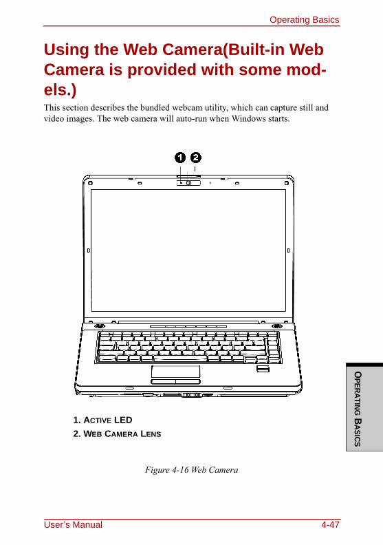
Operating BasicsO
PERATING BASICS
Using the Web Camera(Built-in Web Camera is provided with some mod-els.)This section describes the bundled webcam utility, which can capture still and video images. The web camera will auto-run when Windows starts.
Figure 4-16 Web Camera
1. ACTIVE LED2. WEB CAMERA LENS
User’s Manual 4-47
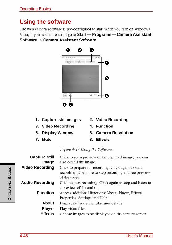
Operating BasicsO
PERA
TING
BAS
ICS
Using the softwareThe web camera software is pre-configured to start when you turn on Windows Vista; if you need to restart it go to Start→ Programs→Camera Assistant Software → Camera Assistant Software
Figure 4-17 Using the Software
1. Capture still images 2. Video Recording3. Video Recording 4. Function5. Display Window 6. Camera Resolution7. Mute 8. Effects
Capture StillImage
Click to see a preview of the captured image; you can also e-mail the image.
Video Recording Click to prepare for recording. Click again to start recording. One more to stop recording and see preview of the video.
Audio Recording Click to start recording, Click again to stop and listen to a preview of the audio.
Function Access additional functions:About, Player, Effects, Properties, Settings and Help.
About Display software manufacturer details.Player Play video files.
Effects Choose images to be displayed on the capture screen.
4-48 User’s Manual
Operating BasicsO
PERATING BASICS
Using the microphoneYour computer has a built-in microphone that can be used to record monaural sounds into your applications. It can also be used to issue voice commands to applications that support such functions.(Built-in microphone is provided with some models)Since your computer has a built-in microphone and speaker, “feedback” may be heard under certain conditions. Feedback occurs when sound from the speaker is picked up in the microphone and amplified back to the speaker, which amplifies it again to the microphone.This feedback occurs repeatedly and causes a very loud, high-pitched noise. It is a common phenomenon that occurs in any sound system when the microphone input is output to the speaker (throughput) and the speaker volume is too loud or too close to the microphone. You can control throughput by adjusting the volume of your speaker or through the Mute function in the Master Volume panel. Refer to your Windows documentation for details on using the Master Volume panel.
Properties Choose from the Options tab to flip, zoom, flicker rate, night mode and backlight compensation; in the Image tab change the colour settings; in the profile tab change the lighting conditions.
Settings Choose from the : Options tab to change the tool posi-tion; the Picture tab to select picture output options such as size, export file and saving location; the Video tab to choose output settings such as Frama Rate, Size, Compression and the file save path; the Audio Device, Compression,Volume and file save path.
Help Displays the help files for the software.
User’s Manual 4-49
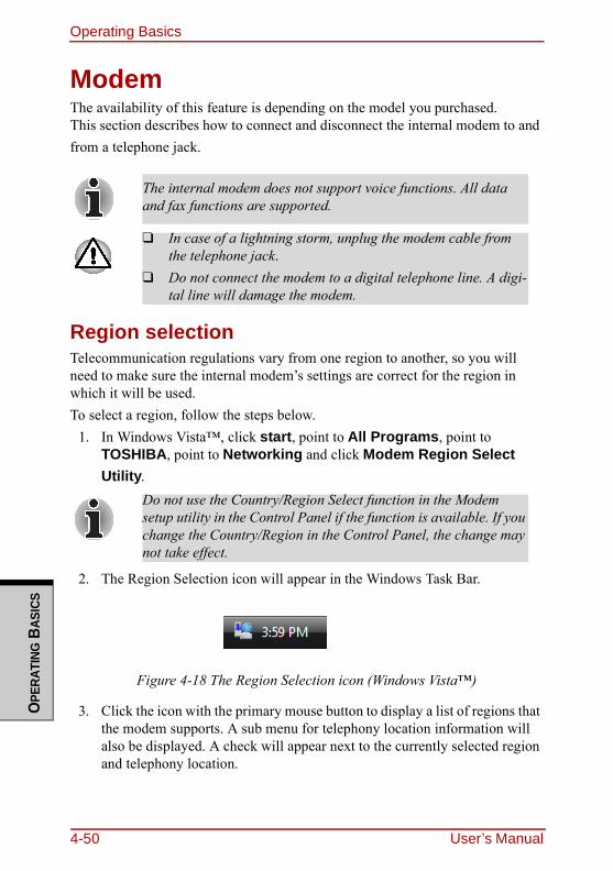
Operating BasicsO
PERA
TING
BAS
ICS
ModemThe availability of this feature is depending on the model you purchased.This section describes how to connect and disconnect the internal modem to and from a telephone jack.
Region selectionTelecommunication regulations vary from one region to another, so you will need to make sure the internal modem’s settings are correct for the region in which it will be used.To select a region, follow the steps below.
1. In Windows Vista™, click start, point to All Programs, point to TOSHIBA, point to Networking and click Modem Region Select Utility.
2. The Region Selection icon will appear in the Windows Task Bar.
Figure 4-18 The Region Selection icon (Windows Vista™)
3. Click the icon with the primary mouse button to display a list of regions that the modem supports. A sub menu for telephony location information will also be displayed. A check will appear next to the currently selected region and telephony location.
The internal modem does not support voice functions. All data and fax functions are supported.
❑ In case of a lightning storm, unplug the modem cable from the telephone jack.
❑ Do not connect the modem to a digital telephone line. A digi-tal line will damage the modem.
Do not use the Country/Region Select function in the Modem setup utility in the Control Panel if the function is available. If you change the Country/Region in the Control Panel, the change may not take effect.
4-50 User’s Manual
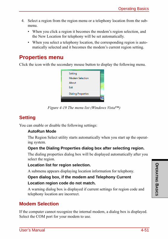
Operating BasicsO
PERATING BASICS
4. Select a region from the region menu or a telephony location from the sub-menu.• When you click a region it becomes the modem’s region selection, and
the New Location for telephony will be set automatically.• When you select a telephony location, the corresponding region is auto-
matically selected and it becomes the modem’s current region setting.
Properties menuClick the icon with the secondary mouse button to display the following menu.
Figure 4-19 The menu list (Windows Vista™)
SettingYou can enable or disable the following settings:
AutoRun ModeThe Region Select utility starts automatically when you start up the operat-ing system.Open the Dialing Properties dialog box after selecting region.The dialing properties dialog box will be displayed automatically after you select the region.Location list for region selection.A submenu appears displaying location information for telephony.Open dialog box, if the modem and Telephony CurrentLocation region code do not match.A warning dialog box is displayed if current settings for region code and telephony location are incorrect.
Modem SelectionIf the computer cannot recognize the internal modem, a dialog box is displayed. Select the COM port for your modem to use.
User’s Manual 4-51
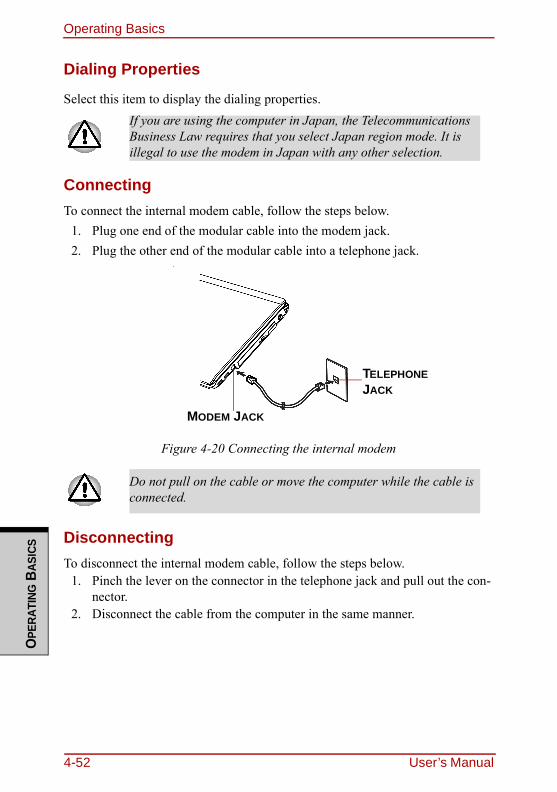
Operating BasicsO
PERA
TING
BAS
ICS
Dialing Properties
Select this item to display the dialing properties.
ConnectingTo connect the internal modem cable, follow the steps below.
1. Plug one end of the modular cable into the modem jack.2. Plug the other end of the modular cable into a telephone jack.
Figure 4-20 Connecting the internal modem
DisconnectingTo disconnect the internal modem cable, follow the steps below.
1. Pinch the lever on the connector in the telephone jack and pull out the con-nector.
2. Disconnect the cable from the computer in the same manner.
If you are using the computer in Japan, the Telecommunications Business Law requires that you select Japan region mode. It is illegal to use the modem in Japan with any other selection.
Do not pull on the cable or move the computer while the cable is connected.
TELEPHONE JACK
MODEM JACK
4-52 User’s Manual
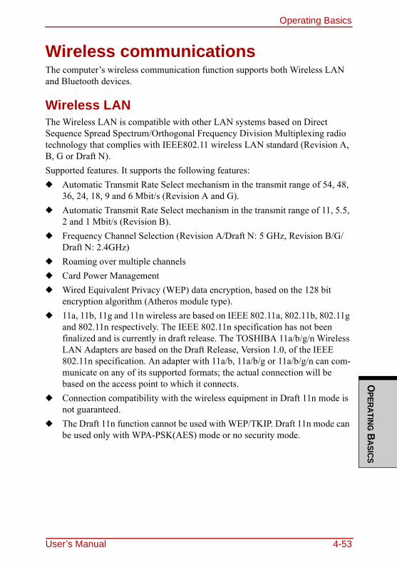
Operating BasicsO
PERATING BASICS
Wireless communicationsThe computer’s wireless communication function supports both Wireless LAN and Bluetooth devices.
Wireless LANThe Wireless LAN is compatible with other LAN systems based on Direct Sequence Spread Spectrum/Orthogonal Frequency Division Multiplexing radio technology that complies with IEEE802.11 wireless LAN standard (Revision A, B, G or Draft N). Supported features. It supports the following features:◆ Automatic Transmit Rate Select mechanism in the transmit range of 54, 48,
36, 24, 18, 9 and 6 Mbit/s (Revision A and G).◆ Automatic Transmit Rate Select mechanism in the transmit range of 11, 5.5,
2 and 1 Mbit/s (Revision B).◆ Frequency Channel Selection (Revision A/Draft N: 5 GHz, Revision B/G/
Draft N: 2.4GHz)◆ Roaming over multiple channels◆ Card Power Management◆ Wired Equivalent Privacy (WEP) data encryption, based on the 128 bit
encryption algorithm (Atheros module type).◆ 11a, 11b, 11g and 11n wireless are based on IEEE 802.11a, 802.11b, 802.11g
and 802.11n respectively. The IEEE 802.11n specification has not been finalized and is currently in draft release. The TOSHIBA 11a/b/g/n Wireless LAN Adapters are based on the Draft Release, Version 1.0, of the IEEE 802.11n specification. An adapter with 11a/b, 11a/b/g or 11a/b/g/n can com-municate on any of its supported formats; the actual connection will be based on the access point to which it connects.
◆ Connection compatibility with the wireless equipment in Draft 11n mode is not guaranteed.
◆ The Draft 11n function cannot be used with WEP/TKIP. Draft 11n mode can be used only with WPA-PSK(AES) mode or no security mode.
User’s Manual 4-53
Operating BasicsO
PERA
TING
BAS
ICS
Security◆ Be sure to enable encryption function. Otherwise your computer will allow
the illegal access by outsider through wireless LAN to cause illegal instruc-tion, eavesdropping, and loss or destruction of stored data. TOSHIBA strongly recommends the customer to enable the encryption function.
◆ TOSHIBA is not liable for the eavesdropping of data due to the use of Wire-less LAN and the damage thereof.
Bluetooth® wireless technology
Bluetooth® wireless technology eliminates the need for cables between electronic devices such as desktop computers, printers and mobile phones. You cannot use the built-in Bluetooth functions and an optional Bluetooth Adapter simultaneously.Bluetooth® wireless technology has the following features:
Worldwide operationThe Bluetooth radio transmitter and receiver operates in the 2.45 GHz band, which is license-free and compatible with radio systems in most countries in the world.
Radio linksYou can easily establish links between two or more devices. The link is main-tained even if the devices are not within line of sight.
SecurityTwo advanced security mechanisms ensure a high level of security:◆ Authentication prevents access to critical data and makes it impossible to
falsify the origin of a message.◆ Encryption prevents eavesdropping and maintains link privacy.
4-54 User’s Manual
Operating BasicsO
PERATING BASICS
Wireless communication switchYou can enable or disable Wireless LAN and Bluetooth functions, with the on/off switch. No transmissions are sent or received when the switch is off. Slide the switch toward the left of the computer to turn it on and toward the right of the computer to turn it off.
Turn the computer off when you enter an airplane and check the carrier’s regula-tions before you use a computer on board.
Wireless communication IndicatorThe wireless communication indicator indicates the status of the wireless com-munication functions.
If you used the Task Bar to disable Wireless LAN, restart the computer or follow the procedures below to enable the system to recognize Wireless LAN. Click Start, open Control Panel, click System and Maintenance, click System, click Device Manager, double-click Network Adapters, and rightclick the wireless device then choose Enable. It may not be possible to make a network connection to a specified network name using the ad hoc network function.If this occurs, the new network(*) will have to be configured for all computers connected to the same network in order to re-enable network connections.* Please be sure to use new network name.
Set the switch to off in airplanes and hospitals. Check the indicator. It will stop glowing when the wireless communication function is off.
Indicator status IndicationIndicator off Wireless communication switch is set to off.
Automatic power down because of overheating.Power malfunction
Indicator glows Wireless communication switch is on.Wireless LAN or Bluetooth is turned on by an appli-cation.
User’s Manual 4-55
Operating BasicsO
PERA
TING
BAS
ICS
LANThe computer has built-in support for Ethernet LAN (10 megabits per second, 10BASE-T) or Fast Ethernet LAN (100 megabits per second, 100BASE-TX)(depending on model you purchased). This section describes how to connect/disconnect to a LAN.
Connecting LAN cable
If you are using Fast Ethernet LAN (100 Mbit/s, 100BASE-TX), be sure to con-nect with a category 5 cable, CAT5, or higher.If you are using Ethernet LAN (10 Mbit/s, 10BASE-T), connect with a category 3 cable, CAT3, or higher.To connect the LAN cable, follow the steps below.
1. Turn off the power to the computer and to all external devices connected to the computer.
Do not install or remove an optional memory module while Wake-up on LAN is enabled.
The Wake-up on LAN function consumes power even when the system is off. Leave the AC adaptor connected while using this feature.
The computer must be configured properly before connecting to a LAN. Logging onto a LAN using the computer’s default settings could cause a malfunction in LAN operation. Check with your LAN administrator regarding set-up procedures.
4-56 User’s Manual
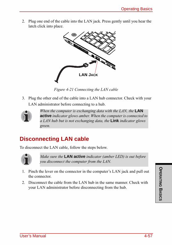
Operating BasicsO
PERATING BASICS
2. Plug one end of the cable into the LAN jack. Press gently until you hear the latch click into place.
Figure 4-21 Connecting the LAN cable
3. Plug the other end of the cable into a LAN hub connector. Check with your LAN administrator before connecting to a hub.
Disconnecting LAN cableTo disconnect the LAN cable, follow the steps below.
1. Pinch the lever on the connector in the computer’s LAN jack and pull out the connector.
2. Disconnect the cable from the LAN hub in the same manner. Check with your LAN administrator before disconnecting from the hub.
When the computer is exchanging data with the LAN, the LAN active indicator glows amber. When the computer is connected to a LAN hub but is not exchanging data, the Link indicator glows green.
Make sure the LAN active indicator (amber LED) is out before you disconnect the computer from the LAN.
LAN JACK
User’s Manual 4-57
Operating BasicsO
PERA
TING
BAS
ICS
Cleaning the computerTo help ensure long, trouble-free operation, keep the computer free of dust and use care with liquids around the computer.◆ Be careful not to spill liquids into the computer. If the computer does get
wet, turn the power off immediately and let the computer dry completely before you turn it on again.
◆ Clean the computer using a slightly damp (with water) cloth. You can use glass cleaner on the display. Spray a small amount of cleaner on a soft, clean cloth and wipe the screen gently with the cloth.
Moving the computerThe computer is designed for rugged durability. However, a few simple precau-tions taken when moving the computer will help ensure trouble-free operation.◆ Make sure all disk activity has ended before moving the computer. Check
the Disk indicator on the computer.◆ If a CD/DVD is in the drive, remove it. Also make sure the drawer is
securely closed.◆ Turn off the power to the computer.◆ Disconnect the AC adaptor and all peripherals before moving the computer.◆ Close the display. Do not pick up the computer by its display panel.◆ Close all port covers.◆ Use the carrying case when transporting the computer.◆ When carrying your computer, be sure to hold it securely so that it does not
fall or hit anything.◆ Do not carry your computer by holding protruded portions.
Never spray cleaner directly onto the computer or let liquid run into any part of it. Never use harsh or caustic chemical products to clean the computer.
4-58 User’s Manual
Operating BasicsO
PERATING BASICS
Heat dispersalTo protect from overheating, the CPU has an internal temperature sensor. If the computer’s internal temperature rises to a certain level, the cooling fan is turned on or the processing speed is lowered. You can select whether to control the CPU temperature by turning on the fan first, then if necessary, lowering the CPU speed. Or, by lowering the CPU speed first, then if necessary, turning on the fan. Use the Cooling Method item of the Basic Setup window in TOSHIBA Power Saver.When the CPU temperature falls to a normal range, the fan is turned off and the CPU operation returns to standard speed.
If the CPU temperature reaches an unacceptably high level with either setting, the system automatically shuts down to prevent damage. Data in memory will be lost.
User’s Manual 4-59
Operating BasicsO
PERA
TING
BAS
ICS
4-60 User’s Manual
User’s Manual 5-1
THE KEYBO
ARD
Chapter 5
The KeyboardThe computer’s keyboard layouts are compatible with a 104/105-key enhanced keyboard. By pressing some keys in combination, all the 104/105-key keyboard functions can be executed on the computer.The number of keys on your keyboard depends on which country/region’s key-board layout your computer is configured with. Keyboards for numerous lan-guages are available.There are five types of keys: typewriter keys, keypad overlay, function keys, soft keys and cursor control keys.
Typewriter keysThe typewriter keys, produce the upper- and lowercase letters, numbers, punctu-ation marks, and special symbols that appear on the screen.There are some differences, however, between using a typewriter and using a computer keyboard:❑ Letters and numbers produced in computer text vary in width. Spaces, which
are created by a “space character,” may also vary depending on line justifi-cation and other factors.
❑ The lowercase l (el) and the number 1 (one) are not interchangeable on com-puters as they are on a typewriter.
❑ The uppercase O (oh) and the 0 (zero) are not interchangeable.❑ The CAPS LOCK function key locks only the alphabetic characters in
uppercase while the shift lock on a typewriter places all keys in the shifted position.
❑ The SHIFT keys, the TAB key, and the BACK SPACE key perform the same function as their typewriter counterparts but also have special com-puter functions.
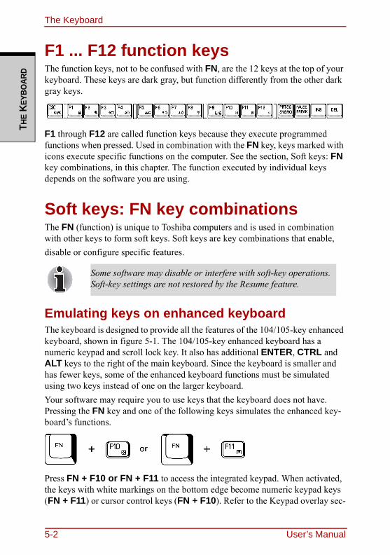
The KeyboardTH
E KE
YBO
ARD
F1 ... F12 function keysThe function keys, not to be confused with FN, are the 12 keys at the top of your keyboard. These keys are dark gray, but function differently from the other dark gray keys.
F1 through F12 are called function keys because they execute programmed functions when pressed. Used in combination with the FN key, keys marked with icons execute specific functions on the computer. See the section, Soft keys: FN key combinations, in this chapter. The function executed by individual keys depends on the software you are using.
Soft keys: FN key combinationsThe FN (function) is unique to Toshiba computers and is used in combination with other keys to form soft keys. Soft keys are key combinations that enable, disable or configure specific features.
Emulating keys on enhanced keyboardThe keyboard is designed to provide all the features of the 104/105-key enhanced keyboard, shown in figure 5-1. The 104/105-key enhanced keyboard has a numeric keypad and scroll lock key. It also has additional ENTER, CTRL and ALT keys to the right of the main keyboard. Since the keyboard is smaller and has fewer keys, some of the enhanced keyboard functions must be simulated using two keys instead of one on the larger keyboard.Your software may require you to use keys that the keyboard does not have. Pressing the FN key and one of the following keys simulates the enhanced key-board’s functions.
Press FN + F10 or FN + F11 to access the integrated keypad. When activated, the keys with white markings on the bottom edge become numeric keypad keys (FN + F11) or cursor control keys (FN + F10). Refer to the Keypad overlay sec-
Some software may disable or interfere with soft-key operations. Soft-key settings are not restored by the Resume feature.
5-2 User’s Manual
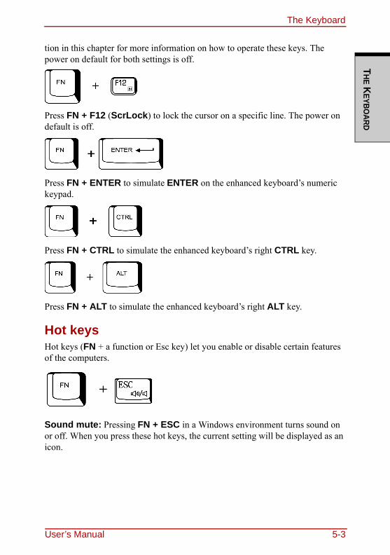
The KeyboardTHE K
EYBOARD
tion in this chapter for more information on how to operate these keys. The power on default for both settings is off.
Press FN + F12 (ScrLock) to lock the cursor on a specific line. The power on default is off.
Press FN + ENTER to simulate ENTER on the enhanced keyboard’s numeric keypad.
Press FN + CTRL to simulate the enhanced keyboard’s right CTRL key.
Press FN + ALT to simulate the enhanced keyboard’s right ALT key.
Hot keysHot keys (FN + a function or Esc key) let you enable or disable certain features of the computers.
Sound mute: Pressing FN + ESC in a Windows environment turns sound on or off. When you press these hot keys, the current setting will be displayed as an icon.
User’s Manual 5-3
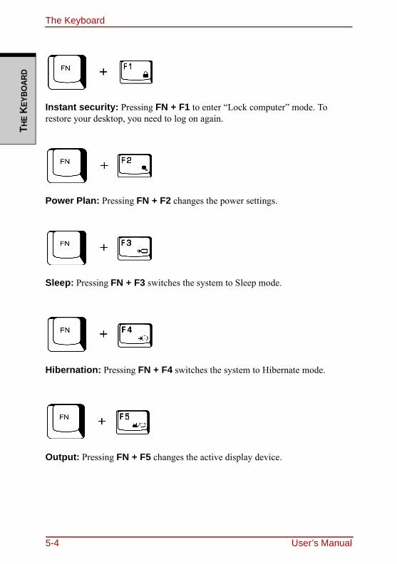
The KeyboardTH
E KE
YBO
ARD
Instant security: Pressing FN + F1 to enter “Lock computer” mode. To restore your desktop, you need to log on again.
Power Plan: Pressing FN + F2 changes the power settings.
Sleep: Pressing FN + F3 switches the system to Sleep mode.
Hibernation: Pressing FN + F4 switches the system to Hibernate mode.
Output: Pressing FN + F5 changes the active display device.
5-4 User’s Manual
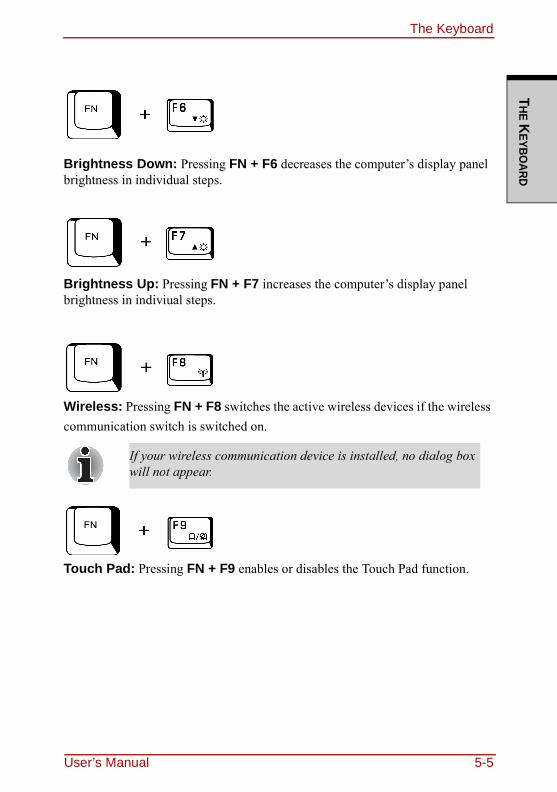
The KeyboardTHE K
EYBOARD
Brightness Down: Pressing FN + F6 decreases the computer’s display panel brightness in individual steps.
Brightness Up: Pressing FN + F7 increases the computer’s display panel brightness in indiviual steps.
Wireless: Pressing FN + F8 switches the active wireless devices if the wireless communication switch is switched on.
Touch Pad: Pressing FN + F9 enables or disables the Touch Pad function.
If your wireless communication device is installed, no dialog box will not appear.
User’s Manual 5-5
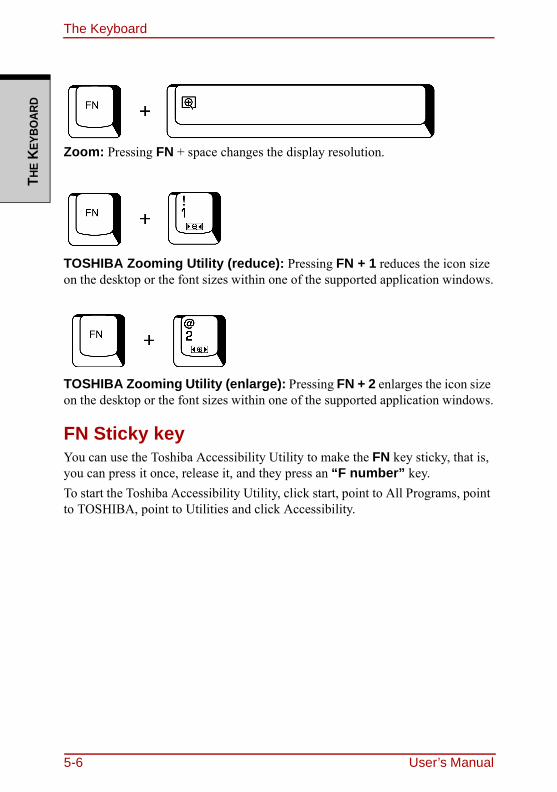
The KeyboardTH
E KE
YBO
ARD
Zoom: Pressing FN + space changes the display resolution.
TOSHIBA Zooming Utility (reduce): Pressing FN + 1 reduces the icon size on the desktop or the font sizes within one of the supported application windows.
TOSHIBA Zooming Utility (enlarge): Pressing FN + 2 enlarges the icon size on the desktop or the font sizes within one of the supported application windows.
FN Sticky keyYou can use the Toshiba Accessibility Utility to make the FN key sticky, that is, you can press it once, release it, and they press an “F number” key.To start the Toshiba Accessibility Utility, click start, point to All Programs, point to TOSHIBA, point to Utilities and click Accessibility.
5-6 User’s Manual
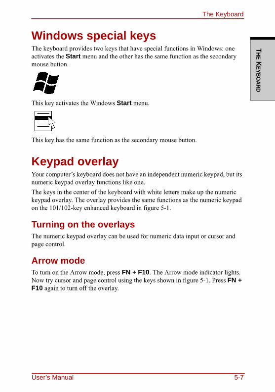
The KeyboardTHE K
EYBOARD
Windows special keysThe keyboard provides two keys that have special functions in Windows: one activates the Start menu and the other has the same function as the secondary mouse button.
This key activates the Windows Start menu.
This key has the same function as the secondary mouse button.
Keypad overlayYour computer’s keyboard does not have an independent numeric keypad, but its numeric keypad overlay functions like one.The keys in the center of the keyboard with white letters make up the numeric keypad overlay. The overlay provides the same functions as the numeric keypad on the 101/102-key enhanced keyboard in figure 5-1.
Turning on the overlaysThe numeric keypad overlay can be used for numeric data input or cursor and page control.
Arrow modeTo turn on the Arrow mode, press FN + F10. The Arrow mode indicator lights. Now try cursor and page control using the keys shown in figure 5-1. Press FN + F10 again to turn off the overlay.
User’s Manual 5-7
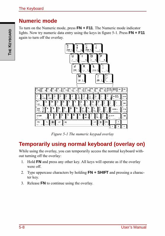
The KeyboardTH
E KE
YBO
ARD
Numeric modeTo turn on the Numeric mode, press FN + F11. The Numeric mode indicator lights. Now try numeric data entry using the keys in figure 5-1. Press FN + F11 again to turn off the overlay.
Figure 5-1 The numeric keypad overlay
Temporarily using normal keyboard (overlay on)While using the overlay, you can temporarily access the normal keyboard with-out turning off the overlay:
1. Hold FN and press any other key. All keys will operate as if the overlay were off.
2. Type uppercase characters by holding FN + SHIFT and pressing a charac-ter key.
3. Release FN to continue using the overlay.
5-8 User’s Manual
The KeyboardTHE K
EYBOARD
Temporarily using overlay (overlay off)While using the normal keyboard, you can temporarily use the keypad overlay without turning it on:
1. Press and hold down FN.2. Check the keyboard indicators. Pressing FN turns on the most recently used
overlay. If the Numeric mode indicator lights, you can use the overlay for numeric entry. If the Arrow mode indicator lights, you can use the overlay for cursor and page control.
3. Release FN to return to normal keyboard operation.
Temporarily changing modesIf the computer is in Numeric mode, you can switch temporarily to Arrow mode by pressing a shift key.If the computer is in Arrow mode, you can switch temporarily to Numeric mode by pressing a shift key.
Generating ASCII charactersNot all ASCII characters can be generated using normal keyboard operation. But, you can generate these characters using their ASCII codes.With the overlay on:
1. Hold down ALT.2. Using the overlay keys, type the ASCII code.3. Release ALT, and the ASCII character appears on the display screen.
With the overlay off:1. Hold ALT + FN.2. Using the overlay keys, type the ASCII code.3. Release ALT + FN, and the ASCII character appears on the display screen.
User’s Manual 5-9

The KeyboardTH
E KE
YBO
ARD
5-10 User’s Manual
PO
WER AND P
OW
ER-U
P MO
DES
Chapter 6
Power and Power-Up ModesThe computer’s power resources include the AC adaptor and internal batteries. This chapter gives details on making the most effective use of these resources including charging and changing batteries, tips for saving battery power, and power up modes.
Power conditionsThe computer’s operating capability and battery charge status are affected by the power conditions: whether an AC adaptor is connected, whether a battery is installed and what the charge level is for the battery.
User’s Manual 6-1
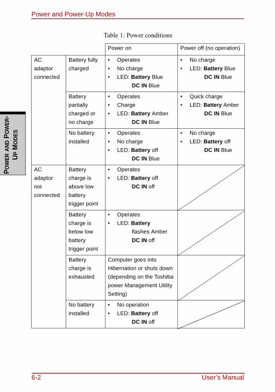
Power and Power-Up ModesPO
WER
AND
PO
WER
-U P
MO
DES
Table 1: Power conditions
Power on Power off (no operation)
AC adaptorconnected
Battery fully charged
• Operates• No charge• LED: Battery Blue
DC IN Blue
• No charge• LED: Battery Blue
DC IN Blue
Battery partially charged or no charge
• Operates• Charge• LED: Battery Amber
DC IN Blue
• Quick charge• LED: Battery Amber
DC IN Blue
No battery installed
• Operates• No charge• LED: Battery off
DC IN Blue
• No charge• LED: Battery off
DC IN Blue
AC adaptornotconnected
Battery charge is above low battery trigger point
• Operates• LED: Battery off
DC IN off
Battery charge is below low battery trigger point
• Operates• LED: Battery
flashes Amber DC IN off
Battery charge is exhausted
Computer goes into Hibernation or shuts down (depending on the Toshiba power Management Utility Setting)
No battery installed
• No operation• LED: Battery off
DC IN off
6-2 User’s Manual
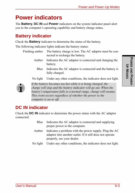
Power and Power-Up ModesP
OW
ER AND PO
WER-
UP M
ODES
Power indicatorsThe Battery, DC IN and Power indicators on the system indicator panel alert you to the computer’s operating capability and battery charge status.
Battery indicatorCheck the Battery indicator to determine the status of the battery.The following indicator lights indicate the battery status:
Flashing amber The battery charge is low. The AC adaptor must be con-nected to recharge the battery.
Amber Indicates the AC adaptor is connected and charging the battery.
Blue Indicates the AC adaptor is connected and the battery is fully charged.
No light Under any other conditions, the indicator does not light.
DC IN indicatorCheck the DC IN indicator to determine the power status with the AC adaptor connected:
Blue Indicates the AC adaptor is connected and supplying proper power to the computer.
Amber Indicates a problem with the power supply. Plug the AC adaptor into another outlet. If it still does not operate properly, see your dealer.
No light Under any other conditions, the indicator does not light.
If the battery becomes too hot while it is being charged, the charge will stop and the battery indicator will go out. When the battery’s temperature falls to a normal range, charge will resume. This event occurs regardless of whether the power to the computer is on or off.
User’s Manual 6-3
Power and Power-Up ModesPO
WER
AND
PO
WER
-U P
MO
DES
Power indicatorCheck the Power indicator to determine the power status.
Blue Indicates power is being supplied to the computer and the computer is turned on.
Blinking amber Indicates the power was turned off while the computer was in Resume mode.
No light Under any other conditions, the indicator does not light.
Battery typesThe computer has two types of batteries:❑ Battery — 3 cell, 6 cell or 9 cell depending on the models
❑ Real Time Clock (RTC) battery
BatteryWhen the AC power cord is not connected, the computer’s main power source is a removable lithium ion battery pack, also referred to in this manual as the bat-tery. You can purchase additional battery packs for extended use of the computer away from an AC power source.
Battery pack(3 cell) is used for Intel(R) GM965 model only.
The battery pack is a lithium ion battery, which can explode if not properly replaced, used, handled or disposed of. Dispose of the battery as required by local ordinances or regulations. Use only batteries recommended by TOSHIBA as replacements.
6-4 User’s Manual
Power and Power-Up ModesP
OW
ER AND PO
WER-
UP M
ODES
The battery recharges the RTC batteries. The battery maintains the state of the computer when you enable Resume.
To ensure that the battery pack maintains its maximum capacity, operate the computer on battery power at least once a month until the battery pack is fully discharged. Refer to Extending battery life in this chapter for procedures. If the computer is continuously operated on AC power, more than a month, the battery may fail to retain a charge. It may not function efficiently over the expected life of the battery and the Battery LED may not indicate a low-battery condition.
Real time clock batteryThe Real Time Clock (RTC) battery provides power for the internal real time clock and calendar. It also maintains the system configuration.If the RTC battery becomes completely discharged, the system loses this data and the real time clock and calendar stop working. The following message appears when you turn on the power:
Check system. Then press [F1] key . . . . . .
When the computer is powered off in Resume mode, and the AC adaptor is not connected, the battery pack supply power to maintain data and programs in memory. If the battery pack is completely discharged, Resume does not function and the computer loses all data in memory.
The following message appears when you turn on the power:ERRPR 0271:Check date and time set-tings.
WARNING 0251:System CMOS checksum bad - Default configuration used.
Press <F1> to resume, <F2> to Setup.
The computer’s RTC battery is a lithium ion battery and should be replaced only by your dealer or by a TOSHIBA service representative. The battery can explode if not properly replaced, used, handled or disposed of. Dispose of the battery as required by local ordinances or regulations.
User’s Manual 6-5
Power and Power-Up ModesPO
WER
AND
PO
WER
-U P
MO
DES
Care and use of the battery packThe battery pack is a vital component of portable computing. Taking proper care of it will help ensure longer operating time on battery power as well as a longer life for your battery pack. Follow the instructions in this section carefully to ensure safe operation and maximum performance.
Safety precautionsMishandling of batteries can cause death, serious injury or property damage. Carefully observe the following advisories:Danger: Indicates an imminently hazardous situation, Which could result in death or serious injury, if you do not follow instructions.Warning: Indicates a potentially hazardous situation, Which could result in death or serious injury, if you do not follow instructions.Caution: Indicates a potentially hazardous situation, Which if not avoided, may result in moderate or minor injury or property damage.Note: Provides important information.
Danger1. Never try to dispose of the battery pack by burning or expose it to a heating
device such as a microwave oven. The battery pack could explode and cause bodily injury.
2. Never try to disassemble, repair or otherwise tamper with a battery pack. The battery pack will overheat and ignite. Leakage of caustic alkaline solu-tion or other electrolytic substances will cause fire or injury, possibly result-ing in death or serious injury.
3. Never short-circuit the battery pack by contacting the terminals with a metal object. A short-circuit can cause fire or otherwise damage the battery pack and possibly cause injury. To avoid accidental short-circuit, always wrap the battery pack in plastic and cover the terminals with electrical tape when storing or disposing of the battery pack.
4. Never puncture the battery pack with a nail or other sharp object. Never strike it with a hammer or other object. Never step on it.
5. Never try to change the battery pack in any manner other than that described in user’s manual. Never connect the battery pack to a plug socked or to a automobile’s cigarette lighter socket. It may rupture or ignite.
6. Use only the battery pack supplied with the computer or other device or an battery pack approved by the computer or device’s manufacturer. Battery
6-6 User’s Manual
Power and Power-Up ModesP
OW
ER AND PO
WER-
UP M
ODES
packs have different voltages and terminal polarities. Use of an improper battery could cause smoke, fire or rupture of the battery pack.
7. Never subject a battery pack to heat, such as storage near a heat source. Exposure to heat can cause the battery pack to ignite, explode or leak caus-tic liquid and cause death or serious injury. It could also fail or malfunction causing data lose.
8. Never expose the battery pack to abnormal shock, vibration or pressure. The battery pack’s internal protective device will fail, causing it to over-heat, explode, ignite or leak caustic liquids possibly resulting in death or serious injury.
9. Never let a battery pack become wet. A wet battery pack will overheat, ignite or rupture possibly resulting in death or serious injury.
Warning1. Never allow caustic electrolyte fluid leaked from a battery pack to contact
your eyes, skin or clothing. If caustic electrolyte fluid should contact your eyes, immediately wash your eyes with large amounts of running water and seek medical attention, to help prevent eye damage. It electrolyte fluid should contact your skin immediately wash it under running water to pre-vent rash. If it contacts your clothes, promptly remove them to prevent the fluid from contacting your skin or eyes.
2. Immediately turn off the power, disconnect the AC adaptor and remove the battery if any of the following events are observed in the battery pack: offensive or unusual odor, excessive heat, discoloration or deformation. Never use the computer again until it has been checked by a TOSHIBA ser-vice provider. It might generate smoke or fire, or the battery pack might rupture.
3. Make sure the battery is securely installed in the computer before attempt-ing to charge the battery pack. Improper installation could generate smoke or fire, or cause the battery pack to rupture.
4. Keep the battery pack out or reach of infants and children. It can cause injury.
User’s Manual 6-7
Power and Power-Up ModesPO
WER
AND
PO
WER
-U P
MO
DES
Caution1. Never continue to use a battery pack after its recharging capacity has
become impaired, or after the display of a warning message indicating that the battery pack’s power is exhausted. Continued use of an exhausted or impaired battery pack could cause the loss of data.
2. Never dispose of battery packs with normal trash. Bring them to your TOSHIBA dealer or to another recycling center to save resources and pre-vent environmental damage. Cover the terminals with electrical tape to pre-vent short-circuits, which could cause the battery pack to ignite or rupture.
3. Use only battery packs recommended by TOSHIBA as replacements.4. Always make sure the battery pack is installed correctly and securely. Oth-
erwise, a battery pack could fall out and possibly cause injury.5. Change the battery pack only in an ambient temperature between 5 and 35
degrees Celsius. Otherwise, the electrolyte solution might leak, battery pack performance might deteriorate and the battery life might be shortened.
6. Be sure to monitor the remaining battery power. If the battery pack and real time clock battery discharge completely. Sleep and Suspend will not func-tion and data in memory will be lose. Also, the computer might register an incorrect time and date. In this case, connect the AC adaptor to recharge the batteries.
7. Never install or remove the battery pack without first turning off the power and disconnecting the AC adaptor. Never remove the battery pack while the computer in Suspend or Sleep mode. Data will be lost.
Note1. Never remove the battery pack while the Wake-up on LAN function is
enabled. Data will be lost. Before you remove a battery pack, disable the Wake-up on LAN function.
2. To ensure the battery pack maintains maximum capacity, operate the com-puter on battery power once a week until the battery pack is fully dis-charged. Refer to the section Extending battery life in this chapter for procedures. If the computer is continuously operated on AC power for an extended period, more than a week, the battery might fail to retain a charge. It might not function efficiently over the expected life of the battery pack and Battery indicator might not indicate a low-battery condition.
3. After the battery pack is charged, avoid leaving the AC adaptor connected and the computer turned off for more than a few hours at a time. Continuing to charge a fully-charged battery pack can damage the battery.
6-8 User’s Manual
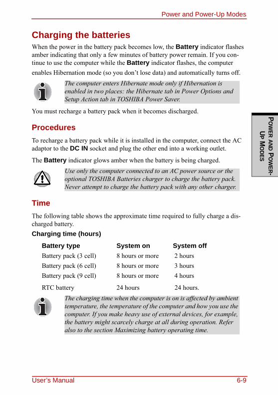
Power and Power-Up ModesP
OW
ER AND PO
WER-
UP M
ODES
Charging the batteriesWhen the power in the battery pack becomes low, the Battery indicator flashes amber indicating that only a few minutes of battery power remain. If you con-tinue to use the computer while the Battery indicator flashes, the computer enables Hibernation mode (so you don’t lose data) and automatically turns off.
You must recharge a battery pack when it becomes discharged.
ProceduresTo recharge a battery pack while it is installed in the computer, connect the AC adaptor to the DC IN socket and plug the other end into a working outlet.
The Battery indicator glows amber when the battery is being charged.
TimeThe following table shows the approximate time required to fully charge a dis-charged battery.Charging time (hours)
Battery type System on System offBattery pack (3 cell) 8 hours or more 2 hoursBattery pack (6 cell) 8 hours or more 3 hoursBattery pack (9 cell) 8 hours or more 4 hours
RTC battery 24 hours 24 hours.
The computer enters Hibernate mode only if Hibernation is enabled in two places: the Hibernate tab in Power Options and Setup Action tab in TOSHIBA Power Saver.
Use only the computer connected to an AC power source or the optional TOSHIBA Batteries charger to charge the battery pack. Never attempt to charge the battery pack with any other charger.
The charging time when the computer is on is affected by ambient temperature, the temperature of the computer and how you use the computer. If you make heavy use of external devices, for example, the battery might scarcely charge at all during operation. Refer also to the section Maximizing battery operating time.
User’s Manual 6-9
Power and Power-Up ModesPO
WER
AND
PO
WER
-U P
MO
DES
Battery charging noticeThe battery may not charge right away under the following conditions:❑ The battery is extremely hot or cold. If the battery is extremely hot, it might
not charge at all. Also, to ensure the battery charges to its full capacity, charge the battery at room temperature of 10° to 30°C (50° to 86°F).
❑ The battery is nearly completely discharged. Leave the AC adaptor con-nected for a few minutes and the battery should begin charging.
The Battery indicator may show a rapid decrease in battery operating time when you try to charge a battery under the following conditions:❑ The battery has not been used for a long time.❑ The battery has completely discharged and been left in the computer for a
long time.❑ A cool battery is installed in a warm computer.In such case, follow the steps below.
1. Fully discharge the battery by leaving it in the computer with the power on until the power automatically shuts off.
2. Plug in the AC adaptor.3. Charge the battery until the Battery indicator glows blue.
Repeat the steps two or three times until the battery recovers normal capacity.Leaving the AC adaptor connected will shorten battery life. At least once a month, run the computer on battery power until the battery is fully discharged, then recharged the battery.
6-10 User’s Manual
Power and Power-Up ModesP
OW
ER AND PO
WER-
UP M
ODES
Monitoring battery capacityRemaining battery power can be monitored in TOSHIBA Power Saver.
❑ Wait at least 16 seconds after turning on the computer before trying to monitor the remaining operating time. The computer needs this time to check the battery’s remaining capacity and to calculate the remaining operating time, based on the cur-rent power consumption rate and remaining battery capacity. The actual remaining operating time may differ slightly from the calculated time.
❑ With repeated discharges and recharges, the battery’s capac-ity will gradually decrease. Therefore, an often used, older battery will not operate for as long as a new battery even when both are fully charged. In this case, TOSHIBA Power Saver will indicate a 100% charge for both the old and new battery, but the displayed estimated time remaining will be shorter for the older battery.
User’s Manual 6-11
Power and Power-Up ModesPO
WER
AND
PO
WER
-U P
MO
DES
Maximizing battery operating timeA battery’s usefulness depends on how long it can supply power on a single charge.How long the charge lasts in a battery depends on:❑ How you configure the computer (for example, whether you enable battery-
power saving options). The computer provides a battery save mode, which can be set in TOSHIBA Power Saver, to conserve battery power. This mode has the following options:• CPU Precessing speed• Screen brightness• Cooling Method• System Sleep• System Hibernation• Monitor Power off• HDD Power off
❑ How often and how long you use the hard disk, CD/DVD-ROM drive and the diskette drive.
❑ How much charge the battery contained to begin with.❑ How you use optional devices, such as an Express Card, to which the battery
supplies power.❑ Enabling Resume mode conserves battery power if you are frequently turn-
ing the computer off and on.❑ Where you store your programs and data. ❑ Closing the display when you are not using the keyboard saves power.❑ Operating time decreases at low temperatures.❑ The condition of the battery terminals. Make sure the battery terminals stay
clean by wiping them with a clean dry cloth before installing the battery pack.
6-12 User’s Manual
Power and Power-Up ModesP
OW
ER AND PO
WER-
UP M
ODES
Retaining data with power offWhen you turn off your computer with fully charged batteries, the batteries retain data for the following approximate time periods:
Battery pack (3 cell) about 1.8 days (Sleep mode)about 15 days (Shutdown mode)
Battery pack (6 cell) about 3.5 days (Sleep mode)about 30 days (Shutdown mode)
Battery pack (9 cell) about 5.5 days (Sleep mode)about 50 days (Shutdown mode)
RTC battery about 3 months
Extending battery lifeTo maximize the life of your battery pack:❑ At least once a month, disconnect the computer from a power source and
operate it on battery power until the battery pack fully discharges. Before doing so, follow the steps below.1. Turn off the computer’s power.2. Disconnect the AC adaptor and turn on the computer’s power. If it does
not turn on go to step 4.3. Operate the computer on battery power for five minutes. If the battery
pack has at least five minutes of operating time, continue operating until the battery pack is fully discharged. If the battery LED flashes or there is some other warning to indicate a low battery, go to step 4.
4. Connect the AC adaptor to the computer and the power cord to a power outlet. The DC IN LED should glow blue, and the Battery LED should glow amber to indicate that the battery pack is being charged. If the DC IN indicator does not glow, power is not being supplied. Check the con-nections for the AC adaptor and power cord.
5. Charge the battery pack until the Battery LED glows blue.❑ If you have extra battery packs, rotate their use.❑ If you will not be using the system for an extended period, more than one
month, remove the battery pack.❑ Disconnect the AC adaptor when the battery is fully charged. Overcharging
makes the battery hot and shortens life.
User’s Manual 6-13
Power and Power-Up ModesPO
WER
AND
PO
WER
-U P
MO
DES
❑ If you are not going to use the computer for more than eight hours, discon-nect the AC adaptor.
❑ Store spare battery packs in a cool dry place out of direct sunlight.
Replacing the battery packWhen the battery pack reaches the end of its operating life you will need to install a new one. If the Battery indicator flashes amber shortly after fully recharging the battery, the battery pack needs to be replaced.You might also replace a discharged battery pack with a charged spare when you are operating your computer away from an AC power source. This section explains how to remove and install battery packs.
Removing the battery packTo replace a discharged battery pack, follow the steps below.
1. Save your work.2. Turn the computer’s power off. Make sure the Power indicator is off.3. Remove all cables connected to the computer.4. Turn the computer upside down with the back of the computer facing you.5. Slide the battery pack locking latch toward the unlock position.
❑ When handling battery pack, be careful not to short circuit the terminals. Also do not drop, hit or otherwise apply impact; do not scratch or break the casing and do not twist or bend the battery pack.
❑ Do not remove the battery pack while the computer is in Sleep mood. Data is stored in RAM, so if the computer loses power it will be lose.
❑ In Hibernation mode, data will be lose if you remove the bat-tery or disconnect the AC adaptor before the save is com-pleted. Wait for the Fixed HDD/ODD indicator to go out.
6-14 User’s Manual
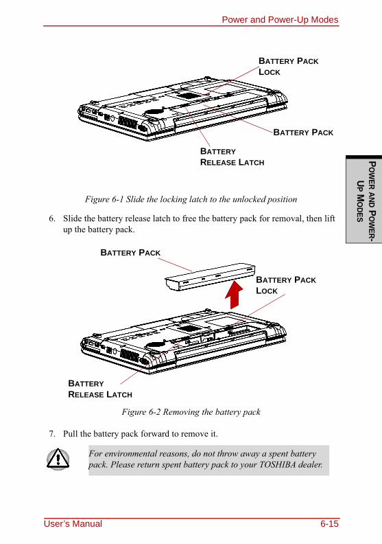
Power and Power-Up ModesP
OW
ER AND PO
WER-
UP M
ODES
Figure 6-1 Slide the locking latch to the unlocked position
6. Slide the battery release latch to free the battery pack for removal, then lift up the battery pack.
Figure 6-2 Removing the battery pack
7. Pull the battery pack forward to remove it.
For environmental reasons, do not throw away a spent battery pack. Please return spent battery pack to your TOSHIBA dealer.
BATTERY PACK
BATTERY PACK LOCK
BATTERY RELEASE LATCH
BATTERY PACK
BATTERY PACK LOCK
BATTERY RELEASE LATCH
User’s Manual 6-15
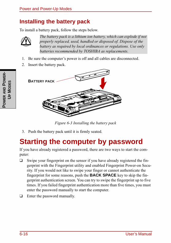
Power and Power-Up ModesPO
WER
AND
PO
WER
-U P
MO
DES
Installing the battery packTo install a battery pack, follow the steps below.
1. Be sure the computer’s power is off and all cables are disconnected.2. Insert the battery pack.
Figure 6-3 Installing the battery pack
3. Push the battery pack until it is firmly seated.
Starting the computer by passwordIf you have already registered a password, there are two ways to start the com-puter:❑ Swipe your fingerprint on the sensor if you have already registered the fin-
gerprint with the Fingerprint utility and enabled Fingerprint Power-on Secu-rity. If you would not like to swipe your finger or cannot authenticate the fingerprint for some reasons, push the BACK SPACE key to skip the fin-gerprint authentication screen. You can try to swipe the fingerprint up to five times. If you failed fingerprint authentication more than five times, you must enter the password manually to start the computer.
❑ Enter the password manually.
The battery pack is a lithium ion battery, which can explode if not properly replaced, used, handled or disposed of. Dispose of the battery as required by local ordinances or regulations. Use only batteries recommended by TOSHIBA as replacements.
BATTERY PACK
6-16 User’s Manual
Power and Power-Up ModesP
OW
ER AND PO
WER-
UP M
ODES
To start up the computer with the user password, follow these steps:1. Turn on the power as described in Chapter 3, Getting Started. The follow-
ing message appears:
Password =
2. Enter the password.
3. Press ENTER.
Power-up modesThe computer has the following power-up modes:❑ Boot: Computer shuts down without saving data. Always save your work
before you turn the computer off in boot mode.❑ Hibernation: Data in memory is saved to the hard disk.
❑ Sleep: Data is maintained in the computer’s main memory. .
Windows utilitiesYou can specify the setting in TOSHIBA Power Saver.
Hot keysYou can use hot keys FN + F3 to enter Sleep mode and FN + F4 to enter Hiber-nation. See Chapter 5, The Keyboard for details.
At this point, the hot keys FN + F1 to F9 do not work. They will function after you enter the password.
If you enter the password incorrectly three times in a row, the computer shuts off. In this case, you must turn the computer back on to retry password entry.
Refer also to the sections Turning on the power and Turning off the power in Chapter 3, Getting Started
User’s Manual 6-17
Power and Power-Up ModesPO
WER
AND
PO
WER
-U P
MO
DES
Panel power on/offYou can set up your computer so that power turns off automatically when you close the display panel. When you open the panel, power turns on in Sleep or Hibernation mode but not in boot mode.
System Auto OffThis feature turns the system off automatically if it is not used for a set duration. The system shuts down in Sleep mode or Hibernation mode in windows.
If the panel power off function is enabled and use Shut down Windows, do not close the display until the shut down function is completed.
6-18 User’s Manual
HW S
ETUP AND P
ASSWO
RDS
Chapter 7
HW Setup and PasswordsThis chapter explains how to use TOSHIBA HW Setup program to configure your computer and how to set passwords.
HW SetupTOSHIBA HW Setup lets you configure settings for Display, CPU, Boot priority, Keyboard, USB, LAN, General and password.
Accessing HW SetupTo start the utility, click the Windows Start button, point to All Programs, click TOSHIBA, click Utilities, and select HWSetup icon.
HW Setup windowThe HW Setup window contains the following tabs: Display, CPU, Boot Priority, Keyboard, USB, LAN, General and Password.There are also three buttons: OK, Cancel and Apply.
If the supervisor password is set, access to the TOSHIBA HW Setup program can be prevented when the user password is used to log on to the computer.
OK Accepts your changes and closes the HW Setup win-dow.
Cancel Closes the window without accepting your changes.Apply Accepts all your changes without closing the HW Setup
window.
User’s Manual 7-1
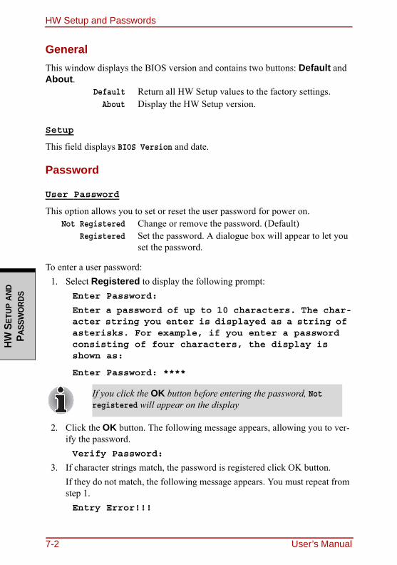
HW Setup and PasswordsHW
SET
UP A
ND
P ASS
WO
RDS
GeneralThis window displays the BIOS version and contains two buttons: Default and About.
Setup
This field displays BIOS Version and date.
Password
User Password
This option allows you to set or reset the user password for power on.
To enter a user password:1. Select Registered to display the following prompt:
Enter Password:
Enter a password of up to 10 characters. The char-acter string you enter is displayed as a string of asterisks. For example, if you enter a password consisting of four characters, the display is shown as:
Enter Password: ****
2. Click the OK button. The following message appears, allowing you to ver-ify the password.Verify Password:
3. If character strings match, the password is registered click OK button.If they do not match, the following message appears. You must repeat from step 1.Entry Error!!!
Default Return all HW Setup values to the factory settings.About Display the HW Setup version.
Not Registered Change or remove the password. (Default)Registered Set the password. A dialogue box will appear to let you
set the password.
If you click the OK button before entering the password, Not registered will appear on the display
7-2 User’s Manual
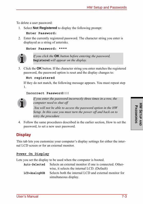
HW Setup and PasswordsHW
SETUP AND
PASSW
ORDS
To delete a user password:1. Select Not Registered to display the following prompt:
Enter Password:
2. Enter the currently registered password. The character string you enter is displayed as a string of asterisks.
Enter Password: ****
3. Click the OK button. If the character string you enter matches the registered password, the password option is reset and the display changes to:Not registered
If they do not match, the following message appears. You must repeat step 1.
Incorrect Password!!!
4. Follow the same procedures described in the earlier section, How to set the password, to set a new user password.
DisplayThis tab lets you customize your computer’s display settings for either the inter-nal LCD screen or for an external monitor.
Power On Display
Lets you set the display to be used when the computer is booted.
If you click the OK button before entering the password, Registered will appear on the display.
If you enter the password incorrectly three times in a row, the computer need to shut off.You will not be able to access the password option in the HW Setup. In this case you must turn the power off and back on to retry the procedure
Auto-Selected Selects an external monitor if one is connected. Other-wise, it selects the internal LCD. (Default)
LCD+AnalogRGB Selects both the internal LCD and external monitor for simultaneous display.
User’s Manual 7-3
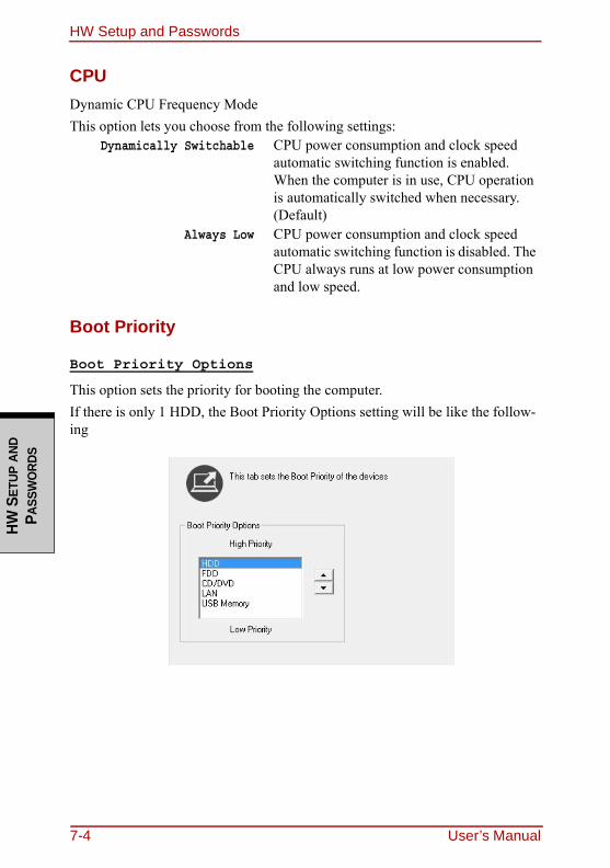
HW Setup and PasswordsHW
SET
UP A
ND
P ASS
WO
RDS
CPUDynamic CPU Frequency ModeThis option lets you choose from the following settings:
Boot Priority
Boot Priority Options
This option sets the priority for booting the computer.If there is only 1 HDD, the Boot Priority Options setting will be like the follow-ing
Dynamically Switchable CPU power consumption and clock speed automatic switching function is enabled. When the computer is in use, CPU operation is automatically switched when necessary. (Default)
Always Low CPU power consumption and clock speed automatic switching function is disabled. The CPU always runs at low power consumption and low speed.
7-4 User’s Manual
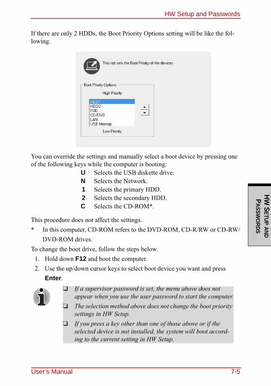
HW Setup and PasswordsHW
SETUP AND
PASSW
ORDS
If there are only 2 HDDs, the Boot Priority Options setting will be like the fol-lowing.
You can override the settings and manually select a boot device by pressing one of the following keys while the computer is booting:
This procedure does not affect the settings.* In this computer, CD-ROM refers to the DVD-ROM, CD-R/RW or CD-RW/
DVD-ROM drives.To change the boot drive, follow the steps below.
1. Hold down F12 and boot the computer.2. Use the up/down cursor keys to select boot device you want and press
Enter.
U Selects the USB diskette drive.N Selects the Network.1 Selects the primary HDD.2 Selects the secondary HDD.C Selects the CD-ROM*.
❑ If a supervisor password is set, the menu above does not appear when you use the user password to start the computer.
❑ The selection method above does not change the boot priority settings in HW Setup.
❑ If you press a key other than one of those above or if the selected device is not installed, the system will boot accord-ing to the current setting in HW Setup.
User’s Manual 7-5
HW Setup and PasswordsHW
SET
UP A
ND
P ASS
WO
RDS
Keyboard
Wake-up on Keyboard
When this feature is enabled and the computer is in sleep mode, you can turn on the computer by pressing any key. It is effective only for the internal keyboard and only when the computer is in sleep mode.
USBLegacy USB Support
Use this option to enable or disable USB Legacy Emulation. If your operating system does not support USB, you can still use a USB mouse and keyboard by setting the USB Legacy Emulation item to Enabled.
LANWake-up on LAN
This features lets the computer’s power be turned on when it receives a wake-up signal from the LAN.
Built-in LAN
Enabled Enables Wake-up on Keyboard.Disabled Disables Wake-up on Keyboard. (Default)
Enabled Enables the USB Legacy Emulation. (Default)Disabled Disables the USB Legacy Emulation.
Enabled Enables Wake-up on LAN.Disabled Wake-up on LAN. (Default)
Do not install or remove an optional memory module while Wake-up on LAN is enabled.
Wake-up on LAN does not work without the AC adaptor. Leave it connected, if you are using this feature.
Enabled Enables built-in LAN functions. (Default)Disabled Disables built-in LAN functions.
7-6 User’s Manual
User’s Manual 8-1
OPTIO
NAL DEVICES
Chapter 8
Optional DevicesOptional devices can expand the computer’s capabilities and its versatility. The following optional devices are available from your TOSHIBA dealer:
Cards/memory❑ Express Cards❑ SD, SDHC, MS, MS Pro, MMC, xD memory cards❑ Memory expansion
Power devices❑ Additional battery pack (6 cell and 9 cell)❑ Additional AC adaptor
Peripheral devices❑ USB FDD Kit❑ External monitor❑ Television❑ HDMI❑ IEEE 1394
Other❑ Security lock
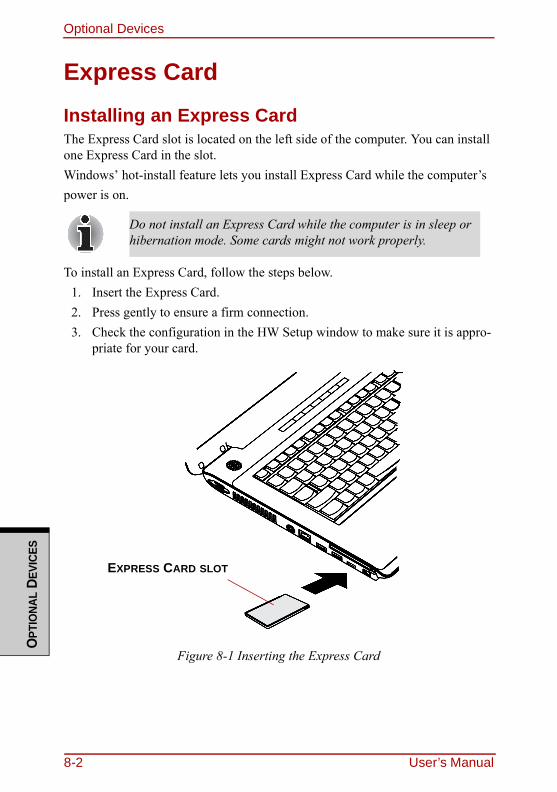
Optional DevicesO
PTIO
NAL
DEVI
CES
Express Card
Installing an Express CardThe Express Card slot is located on the left side of the computer. You can install one Express Card in the slot.Windows’ hot-install feature lets you install Express Card while the computer’s power is on.
To install an Express Card, follow the steps below.1. Insert the Express Card.2. Press gently to ensure a firm connection.3. Check the configuration in the HW Setup window to make sure it is appro-
priate for your card.
Figure 8-1 Inserting the Express Card
Do not install an Express Card while the computer is in sleep or hibernation mode. Some cards might not work properly.
EXPRESS CARD SLOT
8-2 User’s Manual
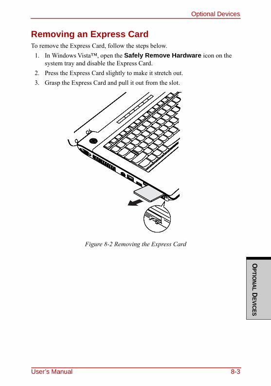
Optional DevicesO
PTIONAL D
EVICES
Removing an Express CardTo remove the Express Card, follow the steps below.
1. In Windows Vista™, open the Safely Remove Hardware icon on the system tray and disable the Express Card.
2. Press the Express Card slightly to make it stretch out.3. Grasp the Express Card and pull it out from the slot.
Figure 8-2 Removing the Express Card
User’s Manual 8-3
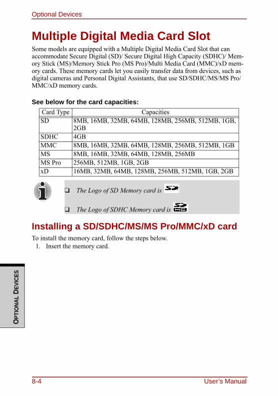
Optional DevicesO
PTIO
NAL
DEVI
CES
Multiple Digital Media Card SlotSome models are equipped with a Multiple Digital Media Card Slot that can accommodate Secure Digital (SD)/ Secure Digital High Capacity (SDHC)/ Mem-ory Stick (MS)/Memory Stick Pro (MS Pro)/Multi Media Card (MMC)/xD mem-ory cards. These memory cards let you easily transfer data from devices, such as digital cameras and Personal Digital Assistants, that use SD/SDHC/MS/MS Pro/MMC/xD memory cards.
See below for the card capacities:
Installing a SD/SDHC/MS/MS Pro/MMC/xD cardTo install the memory card, follow the steps below.
1. Insert the memory card.
Card Type CapacitiesSD 8MB, 16MB, 32MB, 64MB, 128MB, 256MB, 512MB, 1GB,
2GBSDHC 4GBMMC 8MB, 16MB, 32MB, 64MB, 128MB, 256MB, 512MB, 1GBMS 8MB, 16MB, 32MB, 64MB, 128MB, 256MBMS Pro 256MB, 512MB, 1GB, 2GBxD 16MB, 32MB, 64MB, 128MB, 256MB, 512MB, 1GB, 2GB
❑ The Logo of SD Memory card is
❑ The Logo of SDHC Memory card is
8-4 User’s Manual
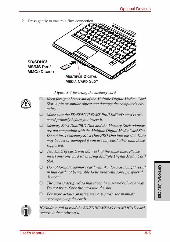
Optional DevicesO
PTIONAL D
EVICES
2. Press gently to ensure a firm connection.
Figure 8-3 Inserting the memory card❑ Keep foreign objects out of the Multiple Digital Media Card
Slot. A pin or similar object can damage the computer's cir-cuitry
❑ Make sure the SD/SDHC/MS/MS Pro/MMC/xD card is ori-ented properly before you insert it.
❑ Memory Stick Duo/PRO Duo and the Memory Stick adaptor are not compatible with the Multiple Digital Media Card Slot. Do not insert Memory Stick Duo/PRO Duo into the slot. Data may be lost or damaged if you use any card other than those supported.
❑ Two kinds of cards will not work at the same time. Please insert only one card when using Multiple Digital Media Card Slot.
❑ Do not format a memory card with Windows as it might result in that card not being able to be used with some peripheral devices.
❑ The card is designed so that it can be inserted only one way. Do not try to force the card into the slot.
❑ For more details on using memory cards, see manuals accompanying the cards
If Windows fail to read the SD/SDHC/MS/MS Pro/MMC/xD card, remove it then reinsert it.
SD/SDHC/MS/MS PRO/MMC/XD CARD
MULTIPLE DIGITAL MEDIA CARD SLOT
User’s Manual 8-5
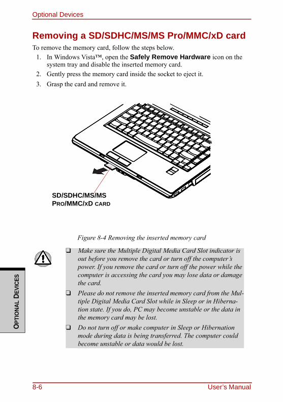
Optional DevicesO
PTIO
NAL
DEVI
CES
Removing a SD/SDHC/MS/MS Pro/MMC/xD cardTo remove the memory card, follow the steps below.
1. In Windows Vista™, open the Safely Remove Hardware icon on the system tray and disable the inserted memory card.
2. Gently press the memory card inside the socket to eject it.3. Grasp the card and remove it.
Figure 8-4 Removing the inserted memory card
❑ Make sure the Multiple Digital Media Card Slot indicator is out before you remove the card or turn off the computer’s power. If you remove the card or turn off the power while the computer is accessing the card you may lose data or damage the card.
❑ Please do not remove the inserted memory card from the Mul-tiple Digital Media Card Slot while in Sleep or in Hiberna-tion state. If you do, PC may become unstable or the data in the memory card may be lost.
❑ Do not turn off or make computer in Sleep or Hibernation mode during data is being transferred. The computer could become unstable or data would be lost.
SD/SDHC/MS/MS PRO/MMC/XD CARD
8-6 User’s Manual
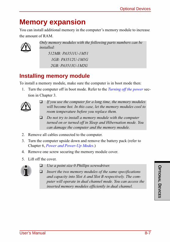
Optional DevicesO
PTIONAL D
EVICES
Memory expansionYou can install additional memory in the computer’s memory module to increase the amount of RAM.
Installing memory moduleTo install a memory module, make sure the computer is in boot mode then:
1. Turn the computer off in boot mode. Refer to the Turning off the power sec-tion in Chapter 3.
2. Remove all cables connected to the computer.3. Turn the computer upside down and remove the battery pack (refer to
Chapter 6, Power and Power-Up Modes.) 4. Remove one screw securing the memory module cover.
5. Lift off the cover.
Only memory modules with the following parts numbers can be installed:
512MB: PA3511U-1M51 1GB: PA3512U-1M1G
2GB: PA3513U-1M2G
❑ If you use the computer for a long time, the memory modules will become hot. In this case, let the memory modules cool to room temperature before you replace them.
❑ Do not try to install a memory module with the computer turned on or turned off in Sleep and Hibernation mode. You can damage the computer and the memory module.
❑ Use a point size 0 Phillips screwdriver.❑ Insert the two memory modules of the same specifications
and capacity into Slot A and Slot B respectively. The com-puter will operate in dual channel mode. You can access the inserted memory modules efficiently in dual channel.
User’s Manual 8-7
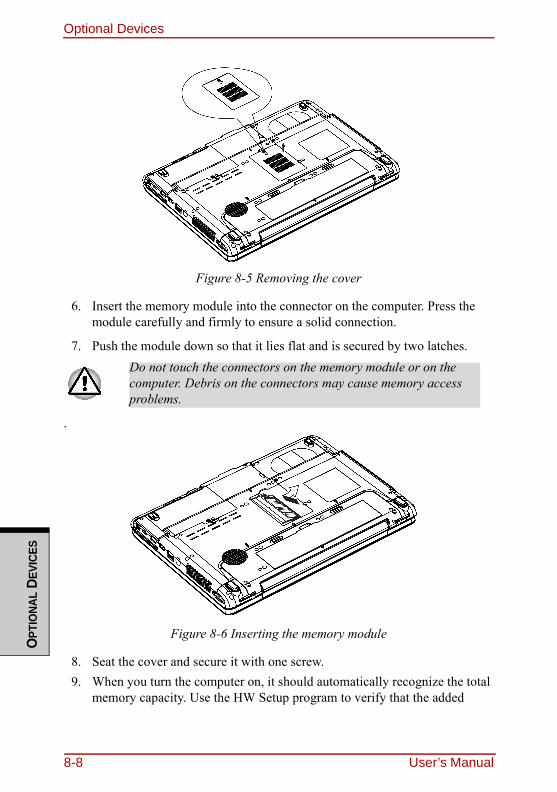
Optional DevicesO
PTIO
NAL
DEVI
CES
Figure 8-5 Removing the cover
6. Insert the memory module into the connector on the computer. Press the module carefully and firmly to ensure a solid connection.
7. Push the module down so that it lies flat and is secured by two latches.
.
Figure 8-6 Inserting the memory module
8. Seat the cover and secure it with one screw.9. When you turn the computer on, it should automatically recognize the total
memory capacity. Use the HW Setup program to verify that the added
Do not touch the connectors on the memory module or on the computer. Debris on the connectors may cause memory access problems.
8-8 User’s Manual
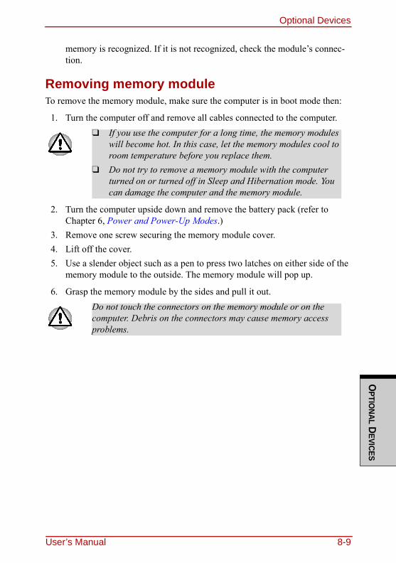
Optional DevicesO
PTIONAL D
EVICES
memory is recognized. If it is not recognized, check the module’s connec-tion.
Removing memory moduleTo remove the memory module, make sure the computer is in boot mode then:
1. Turn the computer off and remove all cables connected to the computer.
2. Turn the computer upside down and remove the battery pack (refer to Chapter 6, Power and Power-Up Modes.)
3. Remove one screw securing the memory module cover.4. Lift off the cover.5. Use a slender object such as a pen to press two latches on either side of the
memory module to the outside. The memory module will pop up.
6. Grasp the memory module by the sides and pull it out.
❑ If you use the computer for a long time, the memory modules will become hot. In this case, let the memory modules cool to room temperature before you replace them.
❑ Do not try to remove a memory module with the computer turned on or turned off in Sleep and Hibernation mode. You can damage the computer and the memory module.
Do not touch the connectors on the memory module or on the computer. Debris on the connectors may cause memory access problems.
User’s Manual 8-9
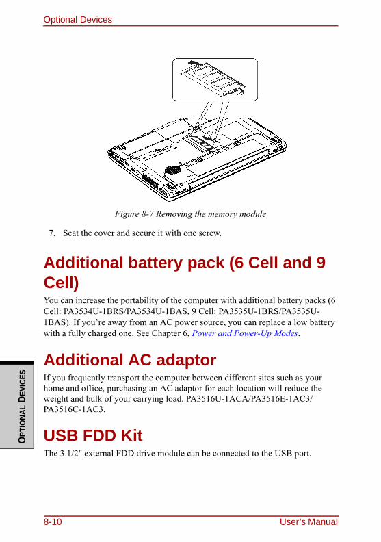
Optional DevicesO
PTIO
NAL
DEVI
CES
Figure 8-7 Removing the memory module
7. Seat the cover and secure it with one screw.
Additional battery pack (6 Cell and 9 Cell)You can increase the portability of the computer with additional battery packs (6 Cell: PA3534U-1BRS/PA3534U-1BAS, 9 Cell: PA3535U-1BRS/PA3535U-1BAS). If you’re away from an AC power source, you can replace a low battery with a fully charged one. See Chapter 6, Power and Power-Up Modes.
Additional AC adaptorIf you frequently transport the computer between different sites such as your home and office, purchasing an AC adaptor for each location will reduce the weight and bulk of your carrying load. PA3516U-1ACA/PA3516E-1AC3/PA3516C-1AC3.
USB FDD KitThe 3 1/2" external FDD drive module can be connected to the USB port.
8-10 User’s Manual
Optional DevicesO
PTIONAL D
EVICES
External monitorAn external analog monitor can be connected to the external monitor port on the computer, Port Replicator. The computer supports VGA and Super VGA video modes. To connect a monitor, follow the steps below.
1. Connect the monitor to the external monitor port.2. Turn the monitor’s power on.
When you turn on the power, the computer automatically recognizes the monitor and determines whether it is color or monochrome.You can use the HW Setup to select between Auto-Selected and Simultaneous displays. Refer to Chapter 7, HW Setup and Passwords.If you have selected Simultaneous under the Display options of the HW Setup, both the external monitor and the internal LCD will be active when you turn on the computer. If Auto-Selected is selected, only the external monitor will be active.To change the display settings, press FN + F5. If you disconnect the monitor before you turn the computer off, be sure to press FN + F5 to switch to the inter-nal display. Refer to Chapter 5, The Keyboard, for details on using hot keys to change the display setting.
If an external monitor is connected to the computer, do not connect the Port Replicator. First disconnect the external monitor from the computer then connect the Port Replicator and use its external monitor port.The Resume feature can be used with an external monitor. Simply enable Resume and the computer will maintain the data as it is displayed on the external monitor.
If you set Simultaneous for the computer’s display, you must set the computer’s display resolution to the same as that of the external monitor or other device, such as a projector.
User’s Manual 8-11
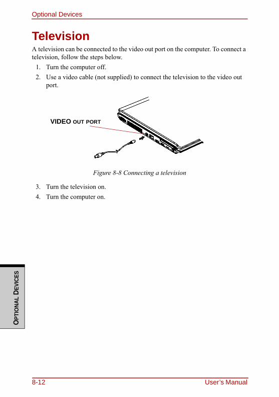
Optional DevicesO
PTIO
NAL
DEVI
CES
TelevisionA television can be connected to the video out port on the computer. To connect a television, follow the steps below.
1. Turn the computer off.2. Use a video cable (not supplied) to connect the television to the video out
port.
Figure 8-8 Connecting a television
3. Turn the television on.4. Turn the computer on.
VIDEO OUT PORT
8-12 User’s Manual
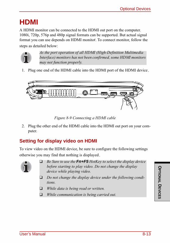
Optional DevicesO
PTIONAL D
EVICES
HDMIA HDMI monitor can be connected to the HDMI out port on the computer. 1080i, 720p, 576p and 480p signal formats can be supported. But actual signal format you can use depends on HDMI monitor. To connect monitor, follow the steps as detailed below:
1. Plug one end of the HDMI cable into the HDMI port of the HDMI device.
Figure 8-9 Connecting a HDMI cable
2. Plug the other end of the HDMI cable into the HDMI out port on your com-puter.
Setting for display video on HDMITo view video on the HDMI device, be sure to configure the following settings otherwise you may find that nothing is displayed.
As the port operation of all HDMI (High-Definition Multimedia Interface) monitors has not been confirmed, some HDMI monitors may not function properly.
❑ Be Sure to use the Fn+F5 HotKey to select the display device before starting to play video. Do not change the display device while playing video.
❑ Do not change the display device under the following condi-tions.
❑ While data is being read or written.❑ While communication is being carried out.
User’s Manual 8-13
Optional DevicesO
PTIO
NAL
DEVI
CES
Settings for audio on HDMITo set the audio device to use the HDMI, follow the steps below.
1. Click Start.2. Click Control Panel.3. Click Hardware and Sound.4. Click Realtek HD Audio Manager.5. Click Digital Output Device (HDMI).6. Click the Set Default Device button.
To set the audio device to use internal speaker, follow the steps below.1. Click Start.2. Click Control Panel.3. Click Hardware and Sound.4. Click Realtek HD Audio Manager.5. Click Speakers.6. Click the Set Default Device button.
i.LINK (IEEE1394)i.LINK (IEEE1394) is provided with some models. It is used for high-speed data transfer for a range of compatible devices such as
1. Digital video cameras2. Hard disk drives3. MO drives
4. CD-RW drives
Precautions1. Make a back-up of your data before transferring it to the computer. There is
a possibility that the original data will be damaged. There is a particular risk that some frames will be deleted in the case of digital video transfer. TOSHIBA assumes no liability for such loss of data.
2. Do not transfer data in areas where static electricity is easily generated or in areas subjected to electronic noise. Data can be destroyed.
i.LINK uses a four-pin connector, which does not carry electric current. External devices will need their own power supply.
8-14 User’s Manual
Optional DevicesO
PTIONAL D
EVICES
3. If you are transferring data through an IEEE1394 hub, do not connect or disconnect other devices from the hub during data transfer. There is a likeli-hood that data will be damaged. Connect all devices to the hub before you turn on the computer’s power.
4. You may not use any copyrighted video or music data copied from a video camera except for your personal enjoyment.
5. If you connect/disconnect an i.LINK device to/from another i.LINK device that is currently exchanging data with the computer, data frames might be dropped.
6. Make sure data transfer has ended or turn off the computer, before you:a. Connect/disconnect an i.LINK device to/from the computer.b. Connect/disconnect an i.LINK device to/from another i.LINK device
that is connected to the computer.
Connecting1. Make sure the connectors are properly aligned and plug the i.LINK
(IEEE1394) cable into the computer.2. Plug the other end of the cable into the device.
Note the following when you use i.LINK:a. You may need to install drivers for your i.LINK devices.b. Not all i.LINK devices have been tested. Therefore, compatibility with
all i.LINK devices cannot be guaranteed.c. Use S100, S200 or S400 cables no longer than three meters.d. Some devices might not support sleep or automatic off functions.e. Do not connect or disconnect an i.LINK device while it is using an
application or when the computer is automatically shutting it down to save power. Data might be destroyed.
f. When multiple IEEE1394 devices are connected to a PC, the devices may not correctly be identified. This problem may occur when Windows Vista™ is restarted while the devices are connected or when the power to the IEEE1394 devices is turned on before the PC is turned on. If it occurs, disconnect the IEEE1394 cables and then reconnect them.
User’s Manual 8-15
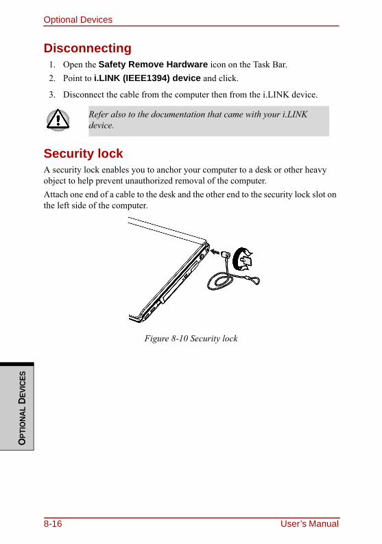
Optional DevicesO
PTIO
NAL
DEVI
CES
Disconnecting1. Open the Safety Remove Hardware icon on the Task Bar.2. Point to i.LINK (IEEE1394) device and click.
3. Disconnect the cable from the computer then from the i.LINK device.
Security lockA security lock enables you to anchor your computer to a desk or other heavy object to help prevent unauthorized removal of the computer.Attach one end of a cable to the desk and the other end to the security lock slot on the left side of the computer.
Figure 8-10 Security lock
Refer also to the documentation that came with your i.LINK device.
8-16 User’s Manual
TROUBLESHO
OTING
Chapter 9
TroubleshootingTOSHIBA designed the computer for durability. However, should problems occur, following the procedures in this chapter can help to determine the cause.All readers should become familiar with this chapter. Knowing what might go wrong can help prevent problems from occurring.
Problem solving processResolving problems will be much easier if you observe the following guidelines:❑ Stop immediately when you recognize a problem exists. Further action may
result in data loss or damage. You may destroy valuable problem-related information that can help solve the problem.
❑ Observe what is happening. Write down what the system is doing and what actions you performed immediately before the problem occurred. If you have a printer attached, print a copy of the screen using the PRTSC(Print Screen) key.
The questions and procedures offered in this chapter are meant as a guide, they are not definitive problem solving techniques. Many problems can be solved simply, but a few may require help from your dealer. If you find you need to con-sult your dealer or others, be prepared to describe the problem in as much detail as possible.
Preliminary checklistConsider the simplest solution first. The items in this checklist are easy to fix and yet can cause what appears to be a serious problem.❑ Make sure you turn on all peripheral devices before you turn on the computer.
This includes your printer and any other external device you are using.❑ Before you attach an external device, turn the computer off. When you turn
the computer back on it recognizes the new device.❑ Make sure all options are set properly in the setup program.❑ Check all cables. Are they correctly and firmly attached? Loose cables can
cause signal errors.❑ Inspect all connecting cables for loose wires and all connectors for loose pins.
User’s Manual 9-1

TroubleshootingTR
OUB
LESH
OO
TING
❑ Check that your diskette is correctly inserted and that the diskette’s write protect tab is correctly set.
Make notes of your observations and keep them in a permanent error log. This will help you describe your problems to your dealer. If a problem recurs, the log will help you identify the problem faster.
Analyzing the problemSometimes the system gives clues that can help you identify why it is malfunc-tioning. Keep the following questions in mind:❑ Which part of the system is not operating properly: keyboard, diskette drives,
hard disk drive, printer, display. Each device produces different symptoms.❑ Is the operating system configuration set properly? Check the configuration
options.❑ What appears on the display screen? Does it display any messages or random
characters? Print a copy of the screen if you have a printer attached. Look up the messages in the software and operating system documentation. Check that all connecting cables are correctly and firmly attached. Loose cables can cause erroneous or intermittent signals.
❑ Do any icons light? Which ones? What color are they? Do they stay on or blink? Write down what you see.
Record your observations so you can describe them to your dealer.Software The problems may be caused by your software or diskette.
If you cannot load a software package, the media (usually a dis-kette) may be damaged or the program might be corrupted. Try loading another copy of the software.If an error message appears while you are using a software package, check the software documentation. These documents usually include a problem solving section or a summary of error messages.Next, check any error messages in the OS documentation.
Hardware If you cannot find a software problem, check your hardware. First run through the items in the preliminary checklist above. If you still cannot correct the problem, try to identify the source. The next section provides checklists for individual components and peripherals.
9-2 User’s Manual
TroubleshootingTRO
UBLESHOO
TING
Hardware and system checklistThis section discusses problems caused by your computer’s hardware or attached peripherals. Basic problems may occur in the following areas:
System start-upWhen the computer does not start properly, check the following items:❑ Self Test❑ Power Sources❑ Power-on Password
❑ System start-up ❑ Express Card❑ Self test ❑ SD/SDHC/MS/MS Pro/MMC/
xD card❑ Power❑ Password ❑ Monitor❑ Keyboard ❑ Sound system
❑ LCD panel ❑ TV output signal❑ Hard disk drive ❑ USB❑ CD-RW/DVD-ROM drive ❑ Modem❑ DVD Super Multi drive ❑ Sleep/Hibernation❑ HD DVD-ROM drive ❑ LAN❑ HD DVD-R drive ❑ Wireless LAN❑ Diskette drive ❑ Bluetooth❑ Infrared port ❑ i.LINK (IEEE 1394)❑ Pointing device❑ Touch/Dual Mode Pad device❑ Fingerprint Sensor
User’s Manual 9-3
TroubleshootingTR
OUB
LESH
OO
TING
Self testWhen the computer starts up, the self-test will be run automatically, and the fol-lowing will be displayed:
In Touch with Tomorrow
TOSHIBA
This message remains on the screen for a few seconds.If the self test is successful, the computer tries to load the operating system.Depending on how the Boot Priority is set in the Hardware Setup, the computer tries to load first from drive A then from drive C, or first from drive C then from drive A.If any of the following conditions are present, the self test failed:❑ The computer stops and does not proceed to display information or mes-
sages.❑ Random characters appear on the screen, and the system does not function
normally.❑ The screen displays an error message.Turn off the computer and check all cable connections. If the test fails again, con-tact your dealer.
PowerWhen the computer is not plugged into an AC adaptor, the battery pack is the pri-mary power source. However, your computer has a number of other power resources, including intelligent power supply and Real Time Clock battery. These resources are interrelated and any one could affect apparent power prob-lems. This section provides check lists for AC adaptor and the main battery. If you cannot resolve a problem after following them, the cause could lie with another power resource. In such case, contact your dealer.
Overheating power downIf the computer’s internal temperature becomes too high, the computer will auto-matically shut down.
9-4 User’s Manual
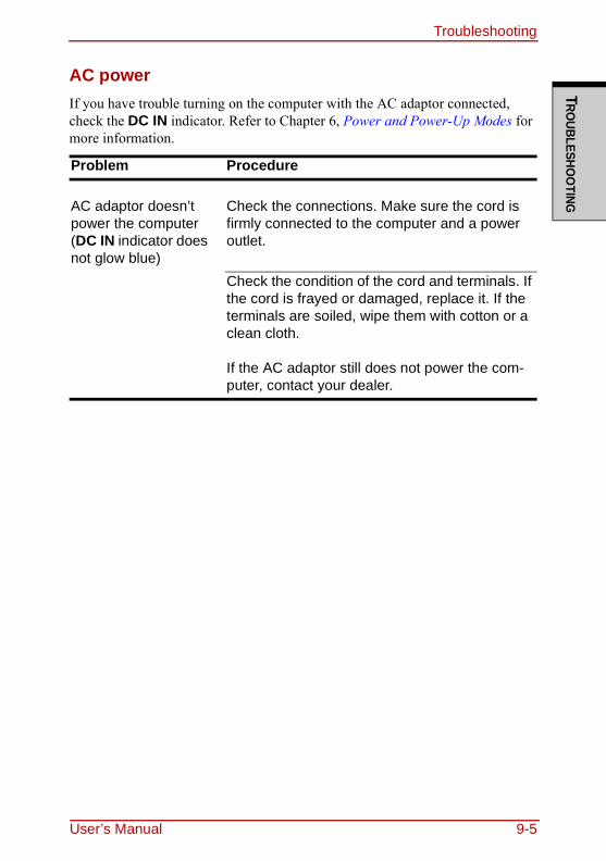
TroubleshootingTRO
UBLESHOO
TING
AC powerIf you have trouble turning on the computer with the AC adaptor connected, check the DC IN indicator. Refer to Chapter 6, Power and Power-Up Modes for more information.
Problem Procedure
AC adaptor doesn’t power the computer (DC IN indicator does not glow blue)
Check the connections. Make sure the cord is firmly connected to the computer and a power outlet.
Check the condition of the cord and terminals. If the cord is frayed or damaged, replace it. If the terminals are soiled, wipe them with cotton or a clean cloth.
If the AC adaptor still does not power the com-puter, contact your dealer.
User’s Manual 9-5
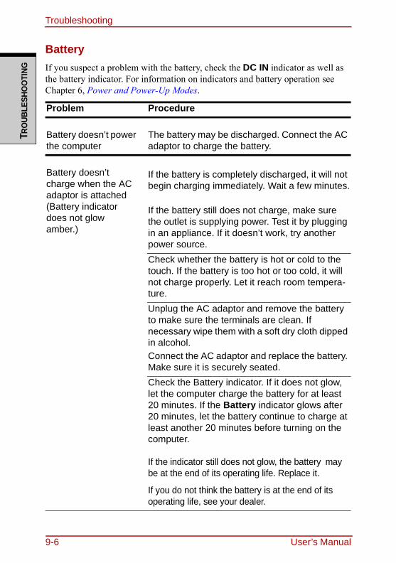
TroubleshootingTR
OUB
LESH
OO
TING
BatteryIf you suspect a problem with the battery, check the DC IN indicator as well as the battery indicator. For information on indicators and battery operation see Chapter 6, Power and Power-Up Modes.
Problem Procedure
Battery doesn’t power the computer
The battery may be discharged. Connect the AC adaptor to charge the battery.
Battery doesn’t charge when the AC adaptor is attached (Battery indicator does not glow amber.)
If the battery is completely discharged, it will not begin charging immediately. Wait a few minutes.
If the battery still does not charge, make sure the outlet is supplying power. Test it by plugging in an appliance. If it doesn’t work, try another power source.Check whether the battery is hot or cold to the touch. If the battery is too hot or too cold, it will not charge properly. Let it reach room tempera-ture.Unplug the AC adaptor and remove the battery to make sure the terminals are clean. If necessary wipe them with a soft dry cloth dipped in alcohol.Connect the AC adaptor and replace the battery. Make sure it is securely seated.Check the Battery indicator. If it does not glow, let the computer charge the battery for at least 20 minutes. If the Battery indicator glows after 20 minutes, let the battery continue to charge at least another 20 minutes before turning on the computer.
If the indicator still does not glow, the battery may be at the end of its operating life. Replace it.
If you do not think the battery is at the end of its operating life, see your dealer.
9-6 User’s Manual
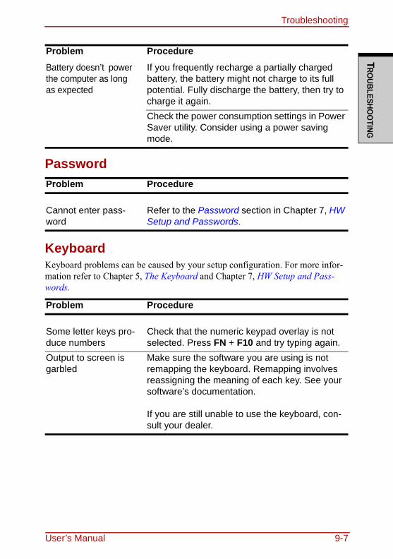
TroubleshootingTRO
UBLESHOO
TING
Password
KeyboardKeyboard problems can be caused by your setup configuration. For more infor-mation refer to Chapter 5, The Keyboard and Chapter 7, HW Setup and Pass-words.
Battery doesn’t power the computer as long as expected
If you frequently recharge a partially charged battery, the battery might not charge to its full potential. Fully discharge the battery, then try to charge it again.Check the power consumption settings in Power Saver utility. Consider using a power saving mode.
Problem Procedure
Cannot enter pass-word
Refer to the Password section in Chapter 7, HW Setup and Passwords.
Problem Procedure
Some letter keys pro-duce numbers
Check that the numeric keypad overlay is not selected. Press FN + F10 and try typing again.
Output to screen is garbled
Make sure the software you are using is not remapping the keyboard. Remapping involves reassigning the meaning of each key. See your software’s documentation.
If you are still unable to use the keyboard, con-sult your dealer.
Problem Procedure
User’s Manual 9-7
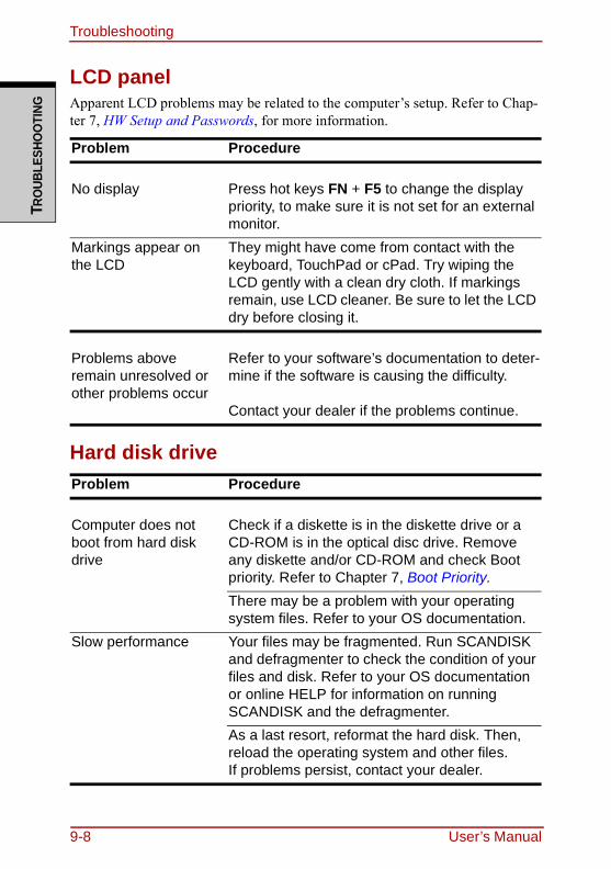
TroubleshootingTR
OUB
LESH
OO
TING
LCD panelApparent LCD problems may be related to the computer’s setup. Refer to Chap-ter 7, HW Setup and Passwords, for more information.
Hard disk drive
Problem Procedure
No display Press hot keys FN + F5 to change the display priority, to make sure it is not set for an external monitor.
Markings appear on the LCD
They might have come from contact with the keyboard, TouchPad or cPad. Try wiping the LCD gently with a clean dry cloth. If markings remain, use LCD cleaner. Be sure to let the LCD dry before closing it.
Problems above remain unresolved or other problems occur
Refer to your software’s documentation to deter-mine if the software is causing the difficulty.
Contact your dealer if the problems continue.
Problem Procedure
Computer does not boot from hard disk drive
Check if a diskette is in the diskette drive or a CD-ROM is in the optical disc drive. Remove any diskette and/or CD-ROM and check Boot priority. Refer to Chapter 7, Boot Priority.There may be a problem with your operating system files. Refer to your OS documentation.
Slow performance Your files may be fragmented. Run SCANDISK and defragmenter to check the condition of your files and disk. Refer to your OS documentation or online HELP for information on running SCANDISK and the defragmenter.As a last resort, reformat the hard disk. Then, reload the operating system and other files.If problems persist, contact your dealer.
9-8 User’s Manual
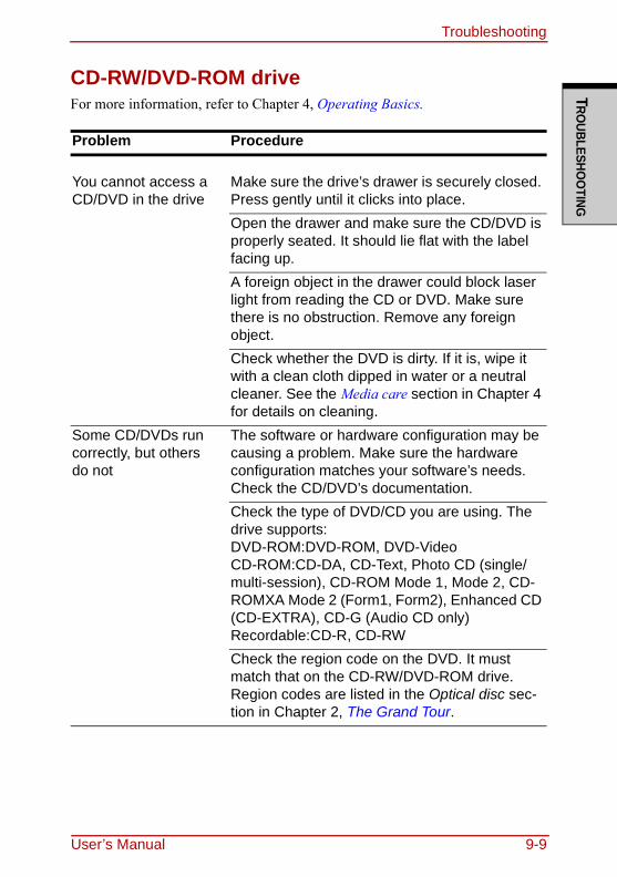
TroubleshootingTRO
UBLESHOO
TING
CD-RW/DVD-ROM driveFor more information, refer to Chapter 4, Operating Basics.
Problem Procedure
You cannot access a CD/DVD in the drive
Make sure the drive’s drawer is securely closed. Press gently until it clicks into place.Open the drawer and make sure the CD/DVD is properly seated. It should lie flat with the label facing up.A foreign object in the drawer could block laser light from reading the CD or DVD. Make sure there is no obstruction. Remove any foreign object.Check whether the DVD is dirty. If it is, wipe it with a clean cloth dipped in water or a neutral cleaner. See the Media care section in Chapter 4 for details on cleaning.
Some CD/DVDs run correctly, but others do not
The software or hardware configuration may be causing a problem. Make sure the hardware configuration matches your software’s needs. Check the CD/DVD’s documentation.Check the type of DVD/CD you are using. The drive supports:DVD-ROM:DVD-ROM, DVD-VideoCD-ROM:CD-DA, CD-Text, Photo CD (single/multi-session), CD-ROM Mode 1, Mode 2, CD-ROMXA Mode 2 (Form1, Form2), Enhanced CD (CD-EXTRA), CD-G (Audio CD only)Recordable:CD-R, CD-RWCheck the region code on the DVD. It must match that on the CD-RW/DVD-ROM drive. Region codes are listed in the Optical disc sec-tion in Chapter 2, The Grand Tour.
User’s Manual 9-9
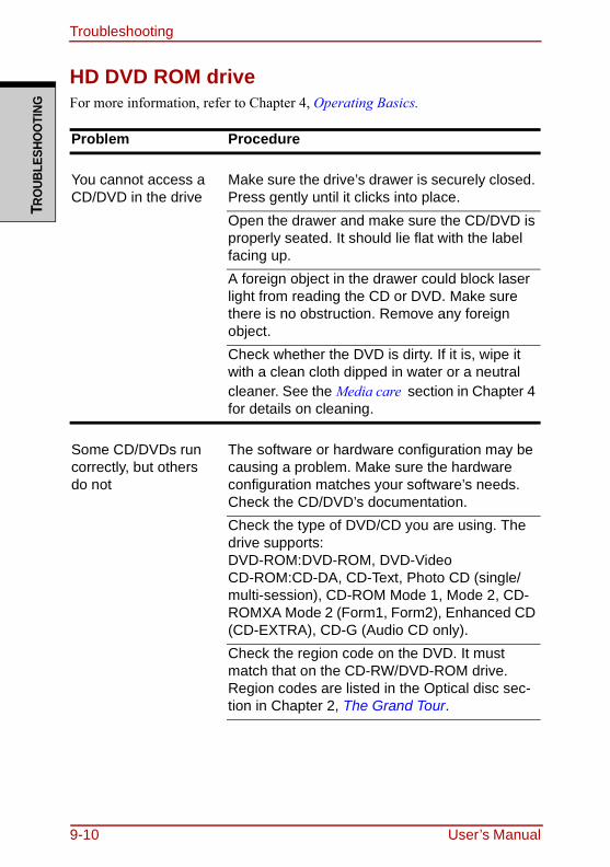
TroubleshootingTR
OUB
LESH
OO
TING
HD DVD ROM driveFor more information, refer to Chapter 4, Operating Basics.
Problem Procedure
You cannot access a CD/DVD in the drive
Make sure the drive’s drawer is securely closed. Press gently until it clicks into place.Open the drawer and make sure the CD/DVD is properly seated. It should lie flat with the label facing up.A foreign object in the drawer could block laser light from reading the CD or DVD. Make sure there is no obstruction. Remove any foreign object.Check whether the DVD is dirty. If it is, wipe it with a clean cloth dipped in water or a neutral cleaner. See the Media care section in Chapter 4 for details on cleaning.
Some CD/DVDs run correctly, but others do not
The software or hardware configuration may be causing a problem. Make sure the hardware configuration matches your software’s needs. Check the CD/DVD’s documentation.Check the type of DVD/CD you are using. The drive supports:DVD-ROM:DVD-ROM, DVD-VideoCD-ROM:CD-DA, CD-Text, Photo CD (single/multi-session), CD-ROM Mode 1, Mode 2, CD-ROMXA Mode 2 (Form1, Form2), Enhanced CD (CD-EXTRA), CD-G (Audio CD only).Check the region code on the DVD. It must match that on the CD-RW/DVD-ROM drive. Region codes are listed in the Optical disc sec-tion in Chapter 2, The Grand Tour.
9-10 User’s Manual
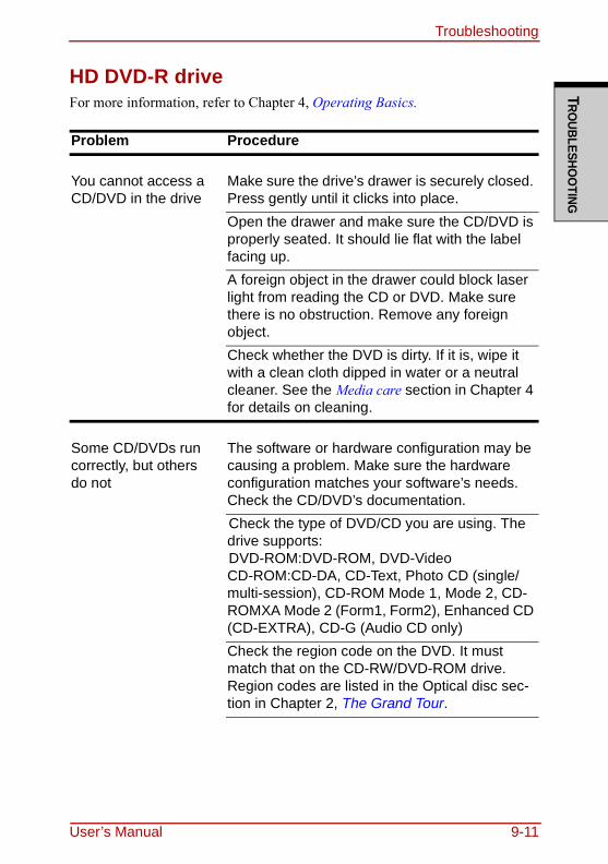
TroubleshootingTRO
UBLESHOO
TING
HD DVD-R driveFor more information, refer to Chapter 4, Operating Basics.
Problem Procedure
You cannot access a CD/DVD in the drive
Make sure the drive’s drawer is securely closed. Press gently until it clicks into place.Open the drawer and make sure the CD/DVD is properly seated. It should lie flat with the label facing up.A foreign object in the drawer could block laser light from reading the CD or DVD. Make sure there is no obstruction. Remove any foreign object.Check whether the DVD is dirty. If it is, wipe it with a clean cloth dipped in water or a neutral cleaner. See the Media care section in Chapter 4 for details on cleaning.
Some CD/DVDs run correctly, but others do not
The software or hardware configuration may be causing a problem. Make sure the hardware configuration matches your software’s needs. Check the CD/DVD’s documentation.Check the type of DVD/CD you are using. The drive supports:DVD-ROM:DVD-ROM, DVD-VideoCD-ROM:CD-DA, CD-Text, Photo CD (single/multi-session), CD-ROM Mode 1, Mode 2, CD-ROMXA Mode 2 (Form1, Form2), Enhanced CD (CD-EXTRA), CD-G (Audio CD only)Check the region code on the DVD. It must match that on the CD-RW/DVD-ROM drive. Region codes are listed in the Optical disc sec-tion in Chapter 2, The Grand Tour.
User’s Manual 9-11
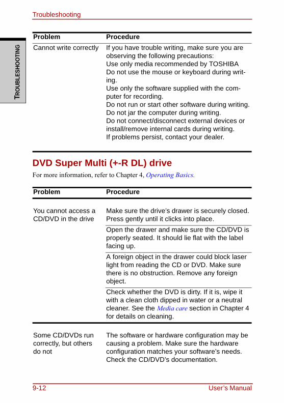
TroubleshootingTR
OUB
LESH
OO
TING
DVD Super Multi (+-R DL) driveFor more information, refer to Chapter 4, Operating Basics.
Cannot write correctly If you have trouble writing, make sure you are observing the following precautions:Use only media recommended by TOSHIBADo not use the mouse or keyboard during writ-ing.Use only the software supplied with the com-puter for recording.Do not run or start other software during writing.Do not jar the computer during writing.Do not connect/disconnect external devices or install/remove internal cards during writing.If problems persist, contact your dealer.
Problem Procedure
You cannot access a CD/DVD in the drive
Make sure the drive’s drawer is securely closed. Press gently until it clicks into place.Open the drawer and make sure the CD/DVD is properly seated. It should lie flat with the label facing up.A foreign object in the drawer could block laser light from reading the CD or DVD. Make sure there is no obstruction. Remove any foreign object.Check whether the DVD is dirty. If it is, wipe it with a clean cloth dipped in water or a neutral cleaner. See the Media care section in Chapter 4 for details on cleaning.
Some CD/DVDs run correctly, but others do not
The software or hardware configuration may be causing a problem. Make sure the hardware configuration matches your software’s needs. Check the CD/DVD’s documentation.
Problem Procedure
9-12 User’s Manual
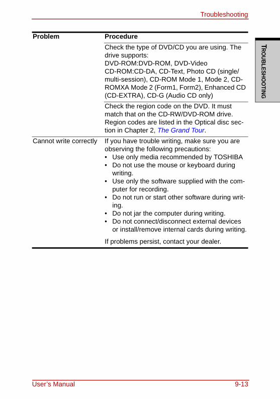
TroubleshootingTRO
UBLESHOO
TING
Check the type of DVD/CD you are using. The drive supports:DVD-ROM:DVD-ROM, DVD-VideoCD-ROM:CD-DA, CD-Text, Photo CD (single/multi-session), CD-ROM Mode 1, Mode 2, CD-ROMXA Mode 2 (Form1, Form2), Enhanced CD (CD-EXTRA), CD-G (Audio CD only)Check the region code on the DVD. It must match that on the CD-RW/DVD-ROM drive. Region codes are listed in the Optical disc sec-tion in Chapter 2, The Grand Tour.
Cannot write correctly If you have trouble writing, make sure you are observing the following precautions:• Use only media recommended by TOSHIBA• Do not use the mouse or keyboard during
writing.• Use only the software supplied with the com-
puter for recording.• Do not run or start other software during writ-
ing.• Do not jar the computer during writing.• Do not connect/disconnect external devices
or install/remove internal cards during writing.
If problems persist, contact your dealer.
Problem Procedure
User’s Manual 9-13
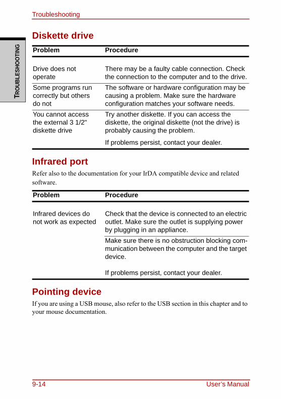
TroubleshootingTR
OUB
LESH
OO
TING
Diskette drive
Infrared portRefer also to the documentation for your IrDA compatible device and related software.
Pointing deviceIf you are using a USB mouse, also refer to the USB section in this chapter and to your mouse documentation.
Problem Procedure
Drive does not operate
There may be a faulty cable connection. Check the connection to the computer and to the drive.
Some programs run correctly but others do not
The software or hardware configuration may be causing a problem. Make sure the hardware configuration matches your software needs.
You cannot access the external 3 1/2" diskette drive
Try another diskette. If you can access the diskette, the original diskette (not the drive) is probably causing the problem.
If problems persist, contact your dealer.
Problem Procedure
Infrared devices do not work as expected
Check that the device is connected to an electric outlet. Make sure the outlet is supplying power by plugging in an appliance.Make sure there is no obstruction blocking com-munication between the computer and the target device.
If problems persist, contact your dealer.
9-14 User’s Manual
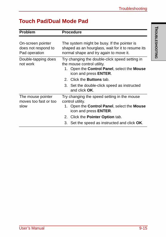
TroubleshootingTRO
UBLESHOO
TING
Touch Pad/Dual Mode Pad
Problem Procedure
On-screen pointer does not respond to Pad operation
The system might be busy. If the pointer is shaped as an hourglass, wait for it to resume its normal shape and try again to move it.
Double-tapping does not work
Try changing the double-click speed setting in the mouse control utility.
1. Open the Control Panel, select the Mouse icon and press ENTER.
2. Click the Buttons tab.3. Set the double-click speed as instructed
and click OK.The mouse pointer moves too fast or too slow
Try changing the speed setting in the mouse control utility.
1. Open the Control Panel, select the Mouse icon and press ENTER.
2. Click the Pointer Option tab.3. Set the speed as instructed and click OK.
User’s Manual 9-15
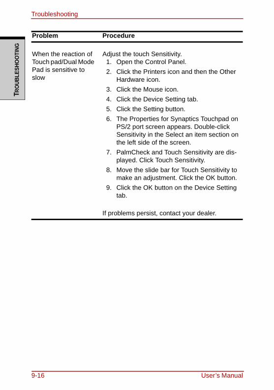
TroubleshootingTR
OUB
LESH
OO
TING
When the reaction of Touch pad/Dual Mode Pad is sensitive to slow
Adjust the touch Sensitivity.1. Open the Control Panel.2. Click the Printers icon and then the Other
Hardware icon.3. Click the Mouse icon.4. Click the Device Setting tab.5. Click the Setting button.6. The Properties for Synaptics Touchpad on
PS/2 port screen appears. Double-click Sensitivity in the Select an item section on the left side of the screen.
7. PalmCheck and Touch Sensitivity are dis-played. Click Touch Sensitivity.
8. Move the slide bar for Touch Sensitivity to make an adjustment. Click the OK button.
9. Click the OK button on the Device Setting tab.
If problems persist, contact your dealer.
Problem Procedure
9-16 User’s Manual
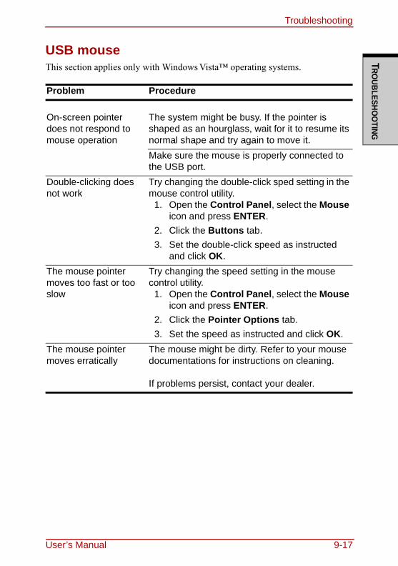
TroubleshootingTRO
UBLESHOO
TING
USB mouseThis section applies only with Windows Vista™ operating systems.
Problem Procedure
On-screen pointer does not respond to mouse operation
The system might be busy. If the pointer is shaped as an hourglass, wait for it to resume its normal shape and try again to move it.Make sure the mouse is properly connected to the USB port.
Double-clicking does not work
Try changing the double-click sped setting in the mouse control utility.
1. Open the Control Panel, select the Mouse icon and press ENTER.
2. Click the Buttons tab.3. Set the double-click speed as instructed
and click OK.The mouse pointer moves too fast or too slow
Try changing the speed setting in the mouse control utility.
1. Open the Control Panel, select the Mouse icon and press ENTER.
2. Click the Pointer Options tab.3. Set the speed as instructed and click OK.
The mouse pointer moves erratically
The mouse might be dirty. Refer to your mouse documentations for instructions on cleaning.
If problems persist, contact your dealer.
User’s Manual 9-17
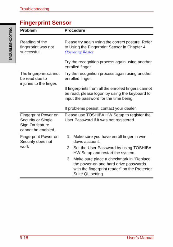
TroubleshootingTR
OUB
LESH
OO
TING
Fingerprint SensorProblem Procedure
Reading of the fingerprint was not successful.
Please try again using the correct posture. Refer to Using the Fingerprint Sensor in Chapter 4, Operating Basics.
Try the recognition process again using another enrolled finger.
The fingerprint cannot be read due to injuries to the finger.
Try the recognition process again using another enrolled finger.
If fingerprints from all the enrolled fingers cannot be read, please logon by using the keyboard to input the password for the time being.
If problems persist, contact your dealer.Fingerprint Power on Security or Single Sign On feature cannot be enabled.
Please use TOSHIBA HW Setup to register the User Password if it was not registered.
Fingerprint Power on Security does not work
1. Make sure you have enroll finger in win-dows account.
2. Set the User Password by using TOSHIBA HW Setup and restart the system.
3. Make sure place a checkmark in "Replace the power-on and hard drive passwords with the fingerprint reader" on the Protector Suite QL setting.
9-18 User’s Manual
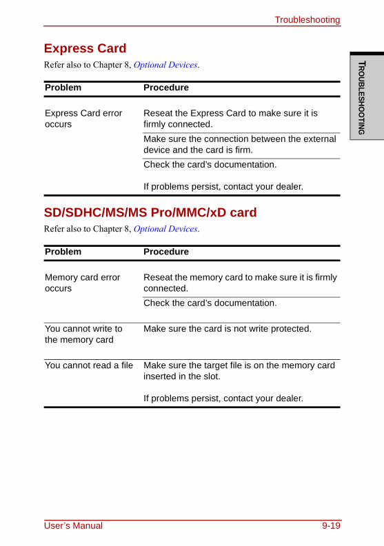
TroubleshootingTRO
UBLESHOO
TING
Express CardRefer also to Chapter 8, Optional Devices.
SD/SDHC/MS/MS Pro/MMC/xD cardRefer also to Chapter 8, Optional Devices.
Problem Procedure
Express Card error occurs
Reseat the Express Card to make sure it is firmly connected.Make sure the connection between the external device and the card is firm.Check the card’s documentation.
If problems persist, contact your dealer.
Problem Procedure
Memory card error occurs
Reseat the memory card to make sure it is firmly connected.Check the card’s documentation.
You cannot write to the memory card
Make sure the card is not write protected.
You cannot read a file Make sure the target file is on the memory card inserted in the slot.
If problems persist, contact your dealer.
User’s Manual 9-19
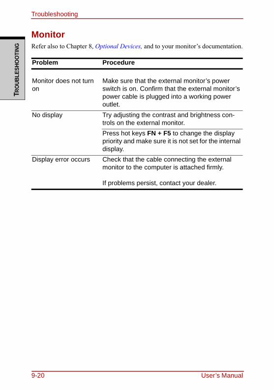
TroubleshootingTR
OUB
LESH
OO
TING
MonitorRefer also to Chapter 8, Optional Devices, and to your monitor’s documentation.
Problem Procedure
Monitor does not turn on
Make sure that the external monitor’s power switch is on. Confirm that the external monitor’s power cable is plugged into a working power outlet.
No display Try adjusting the contrast and brightness con-trols on the external monitor.Press hot keys FN + F5 to change the display priority and make sure it is not set for the internal display.
Display error occurs Check that the cable connecting the external monitor to the computer is attached firmly.
If problems persist, contact your dealer.
9-20 User’s Manual
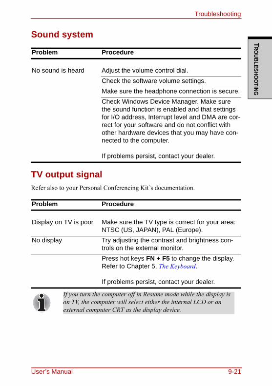
TroubleshootingTRO
UBLESHOO
TING
Sound system
TV output signalRefer also to your Personal Conferencing Kit’s documentation.
Problem Procedure
No sound is heard Adjust the volume control dial.Check the software volume settings.Make sure the headphone connection is secure.Check Windows Device Manager. Make sure the sound function is enabled and that settings for I/O address, Interrupt level and DMA are cor-rect for your software and do not conflict with other hardware devices that you may have con-nected to the computer.
If problems persist, contact your dealer.
Problem Procedure
Display on TV is poor Make sure the TV type is correct for your area: NTSC (US, JAPAN), PAL (Europe).
No display Try adjusting the contrast and brightness con-trols on the external monitor.Press hot keys FN + F5 to change the display. Refer to Chapter 5, The Keyboard.
If problems persist, contact your dealer.
If you turn the computer off in Resume mode while the display is on TV, the computer will select either the internal LCD or an external computer CRT as the display device.
User’s Manual 9-21
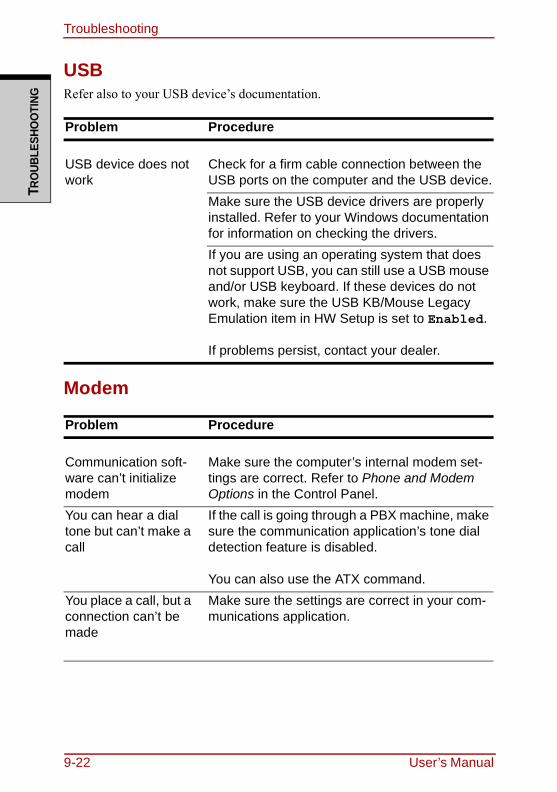
TroubleshootingTR
OUB
LESH
OO
TING
USBRefer also to your USB device’s documentation.
Modem
Problem Procedure
USB device does not work
Check for a firm cable connection between the USB ports on the computer and the USB device.Make sure the USB device drivers are properly installed. Refer to your Windows documentation for information on checking the drivers.If you are using an operating system that does not support USB, you can still use a USB mouse and/or USB keyboard. If these devices do not work, make sure the USB KB/Mouse Legacy Emulation item in HW Setup is set to Enabled.
If problems persist, contact your dealer.
Problem Procedure
Communication soft-ware can’t initialize modem
Make sure the computer’s internal modem set-tings are correct. Refer to Phone and Modem Options in the Control Panel.
You can hear a dial tone but can’t make a call
If the call is going through a PBX machine, make sure the communication application’s tone dial detection feature is disabled.
You can also use the ATX command.You place a call, but a connection can’t be made
Make sure the settings are correct in your com-munications application.
9-22 User’s Manual
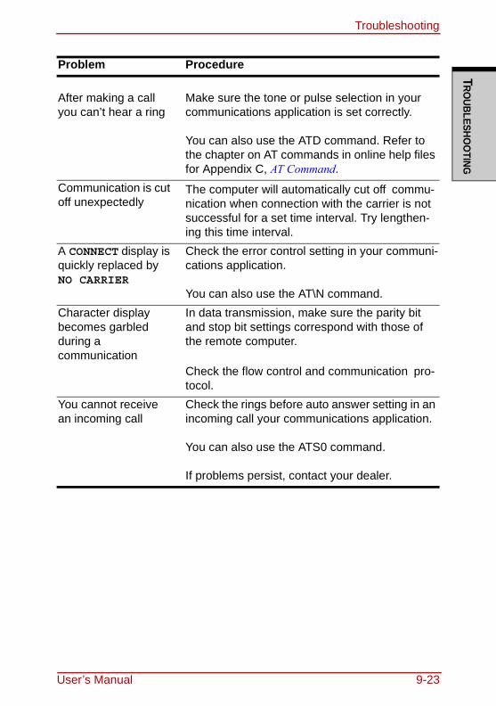
TroubleshootingTRO
UBLESHOO
TING
After making a call you can’t hear a ring
Make sure the tone or pulse selection in your communications application is set correctly.
You can also use the ATD command. Refer to the chapter on AT commands in online help files for Appendix C, AT Command.
Communication is cut off unexpectedly
The computer will automatically cut off commu-nication when connection with the carrier is not successful for a set time interval. Try lengthen-ing this time interval.
A CONNECT display is quickly replaced by NO CARRIER
Check the error control setting in your communi-cations application.
You can also use the AT\N command.Character display becomes garbled during a communication
In data transmission, make sure the parity bit and stop bit settings correspond with those of the remote computer.
Check the flow control and communication pro-tocol.
You cannot receive an incoming call
Check the rings before auto answer setting in an incoming call your communications application.
You can also use the ATS0 command.
If problems persist, contact your dealer.
Problem Procedure
User’s Manual 9-23
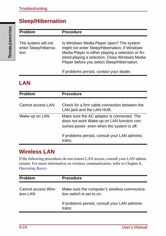
TroubleshootingTR
OUB
LESH
OO
TING
Sleep/Hibernation
LAN
Wireless LANIf the following procedures do not restore LAN access, consult your LAN admin-istrator. For more information on wireless communication, refer to Chapter 4, Operating Basics.
Problem Procedure
The system will not enter Sleep/Hiberna-tion
Is Windows Media Player open? The system might not enter Sleep/Hibernation, if Windows Media Player is either playing a selection or fin-ished playing a selection. Close Windows Media Player before you select Sleep/Hibernation.
If problems persist, contact your dealer.
Problem Procedure
Cannot access LAN Check for a firm cable connection between the LAN jack and the LAN HUB.
Wake-up on LAN Make sure the AC adaptor is connected. The does not work Wake-up on LAN function con-sumes power even when the system is off.
If problems persist, consult your LAN adminis-trator.
Problem Procedure
Cannot access Wire-less LAN
Make sure the computer’s wireless communica-tion switch is set to on.
If problems persist, consult your LAN adminis-trator.
9-24 User’s Manual
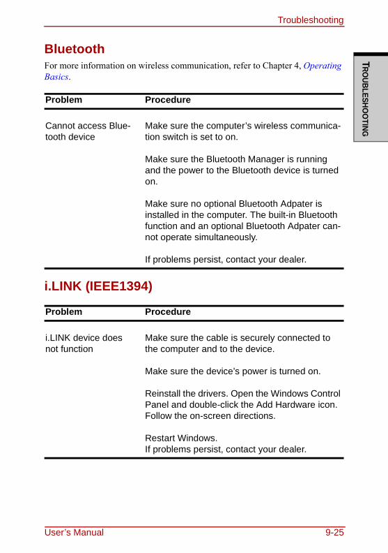
TroubleshootingTRO
UBLESHOO
TING
BluetoothFor more information on wireless communication, refer to Chapter 4, Operating Basics.
i.LINK (IEEE1394)
Problem Procedure
Cannot access Blue-tooth device
Make sure the computer’s wireless communica-tion switch is set to on.
Make sure the Bluetooth Manager is running and the power to the Bluetooth device is turned on.
Make sure no optional Bluetooth Adpater is installed in the computer. The built-in Bluetooth function and an optional Bluetooth Adpater can-not operate simultaneously.
If problems persist, contact your dealer.
Problem Procedure
i.LINK device does not function
Make sure the cable is securely connected to the computer and to the device.
Make sure the device’s power is turned on.
Reinstall the drivers. Open the Windows Control Panel and double-click the Add Hardware icon. Follow the on-screen directions.
Restart Windows.If problems persist, contact your dealer.
User’s Manual 9-25
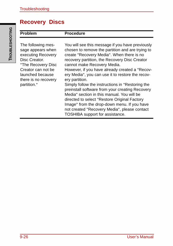
TroubleshootingTR
OUB
LESH
OO
TING
Recovery Discs
Problem Procedure
The following mes-sage appears when executing Recovery Disc Creator."The Recovery Disc Creator can not be launched because there is no recovery partition."
You will see this message if you have previously chosen to remove the partition and are trying to create "Recovery Media". When there is no recovery partition, the Recovery Disc Creator cannot make Recovery Media.However, if you have already created a "Recov-ery Media", you can use it to restore the recov-ery partition.Simply follow the instructions in "Restoring the preinstall software from your creating Recovery Media" section in this manual. You will be directed to select "Restore Original Factory Image" from the drop-down menu. If you have not created "Recovery Media", please contact TOSHIBA support for assistance.
9-26 User’s Manual
TroubleshootingTRO
UBLESHOO
TING
TOSHIBA supportIf you require any additional help using your computer or if you are having prob-lems operating the computer, you may need to contact TOSHIBA for additional technical assistance.
Before you callSome problems you experience may be related to software or the operating sys-tem, it is important to investigate other sources of assistance first. Before con-tacting TOSHIBA, try the following:❑ Review troubleshooting sections in the documentation for software and
peripheral devices.❑ If a problem occurs when you are running software applications, consult the
software documentation for troubleshooting suggestions. Call the software company’s technical support for assistance.
❑ Consult the dealer you purchased your computer and/or software from. They are your best sources for current information and support.
Where to writeIf you are still unable to solve the problem and suspect that it is hardware related, write to TOSHIBA at the nearest location listed on the below.
User’s Manual 9-27
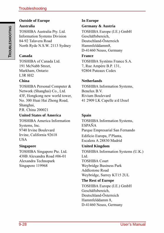
TroubleshootingTR
OUB
LESH
OO
TING
Outside of Europe In EuropeAustraliaTOSHIBA Australia Pty. Ltd.Information Systems Division84-92 Talavera RoadNorth Ryde N.S.W. 2113 Sydney
Germany & AustriaTOSHIBA Europe (I.E.) GmbHGeschäftsbereich,Deutschland-ÖsterreichHammfelddamm8,D-41460 Neuss, Germany
CanadaTOSHIBA of Canada Ltd.191 McNabb Street,Markham, OntarioL3R 8H2
FranceTOSHIBA Systèms France S.A.7, Rue Ampère B.P. 131,92804 Puteaux Cedex
ChinaTOSHIBA Personal Computer &Network (Shanghai) Co., Ltd.43F, Hongkong new world tower,No. 300 Huai Hai Zhong Road,Shanghai,P.R. China 200021
NetherlandsTOSHIBA Information Systems,Benelux B.V.Rivium Boulevard41 2909 LK Capelle a/d IJssel
United States of AmericaTOSHIBA America InformationSystems, Inc.9740 Irvine BoulevardIrvine, California 92618USA
SpainTOSHIBA Information Systems,ESPAÑAParque Empresarial San FernandoEdificio Europa, la Planta,Escalera A 28830 Madrid
SingaporeTOSHIBA Singapore Pte. Ltd.438B Alexandra Road #06-01Alexandra TechnoparkSingapore 119968
United KingdomTOSHIBA Information Systems (U.K.) Ltd.TOSHIBA CourtWeybridge Business ParkAddlestone RoadWeybridge, Surrey KT15 2ULThe Rest of EuropeTOSHIBA Europe (I.E.) GmbHGeschäftsbereich,Deutschland-ÖsterreichHammfelddamm 8,D-41460 Neuss, Germany
9-28 User’s Manual
DISCLAIM
ERS
Chapter 10
DisclaimersThis chapter slates the Disclaimer(s) information applicable to TOSHIBA com-puters.
CPUCentral Processing Unit ("CPU") Performance Disclaimer.CPU performance in your computer product may vary from specifications under the following conditions:❑ use of certain external peripheral products❑ use of battery power instead of AC power❑ use of certain multimedia, computer generated graphics or video applica-
tions❑ use of standard telephone lines or low speed network connections❑ use of complex modeling software, such as high end computer aided design
applications❑ use of several applications or functionalities simultaneously❑ use of computer in areas with low air pressure (high altitude > 1,000 meters
or > 3,280 feet above sea level)❑ use of computer at temperatures outside the range of 5°C TO 30°C (41°F TO
86°F) or > 25°C (77°F) at high altitude (all temperature references are approximate and may vary depending on the specific computer model-please refer to your PC documentation or visit the Toshiba website at www.pcsupport.toshiba.com for details).
CPU performance may also vary from specifications due to design configuration.Under some conditions, your computer product may automatically shut-down. This is a normal protective feature designed to reduce the risk of lost data or damage to the product when used outside recommended conditions. To avoid risk of lost data, always make back-up copies of data by periodically storing it on an external storage medium. For optimum performance, use your computer prod-uct only under recommended conditions. Read additional restrictions in your
User’s Manual 10-1
DisclaimersDI
SCLA
IMER
S
product documentation. Contact Toshiba technical service and support, refer to TOSHIBA support section in chapter 9 Troubleshooting for more information.64-Bit Computing. 64-bit processors are designed to take advantage of 32 and 64 bit computing.64-bit computing requires that the following hardware and software require-ments are met:
• 64-bit Operating System• 64-bit CPU, Chipset and BIOS (Basic Input/Output System)• 64-bit Device drivers• 64-bit applications
Certain device drivers and/or applications may not be compatible with a 64-bit CPU and therefore may not function properly. A 32-bit version of the operating system is preinstalled on your computer unless explicitly stated that the operating system is 64-bit. See "www.pcsupport.toshiba.com" for more information.
Memory (Main System)Part of the main system memory may be used by the graphics system for graph-ics performance and therefore reduce the amount of main system memory avail-able for other computing activities. The amount of main system memory allocated to support graphics may vary depending on the graphics system, appli-cations utilized, system memory size and other factors.For PC's configured with 4GB of system memory, the full system memory space for computing activities will be considerably less and will vary by model and system configuration.
Battery LifeBattery life may vary considerably depending on product model, configuration, applications, power management settings and features utilized, as well as the nat-ural performance variations produced by the design of individual components. Published battery life numbers are achieved on select models and configurations tested by Toshiba at the time of publication. Recharge time varies depending on usage. Battery may not charge while computer is consuming full power.After a period of time, the battery will lose its ability to perform at maximum capacity and will need to be replaced. This is a normal phenomenon for all bat-teries. To purchase a new battery pack, see the accessories information that is
10-2 User’s Manual
DisclaimersD
ISCLAIMERS
shipped with your computer, or visit the Toshiba web site at www.pcsup-port.toshiba.com.
HDD Drive Capacity1 Gigabyte (GB) means = 1,000,000,000 bytes using powers of 10. The com-puter operating system, however, reports storage capacity using powers of 2 for
the definition of 1 GB = = 1,073,741,824 bytes, and therefore shows less storage capacity. Available storage capacity will also be less if the product includes one or more pre-installed operating systems, such as Microsoft Win-dows and/or pre-installed software applications, or media content. Actual for-matted capacity may vary.
LCDOver a period of time, and depending on the usage of the computer, the bright-ness of the LCD screen will deteriorate. This is an intrinsic characteristic of LCD technology.Maximum brightness is only available when operating in AC power mode. The screen will dim when the computer is operated on battery power and you will not be able to increase the brightness of the screen.
Graphics Processor Unit ("GPU")Graphics processor unit ("GPU") performance may vary depending on product model, design configuration, applications, power management settings and fea-tures utilized. GPU performance is only optimized when operating in AC power mode and may decrease considerably when operating in battery power mode.
109
230
User’s Manual 10-3
DisclaimersDI
SCLA
IMER
S
Wireless LANThe transmission speed over the wireless LAN and the distance over which wire-less LAN can reach may vary depending on surrounding electromagnetic envi-ronment, obstacles, access point design and configuration, and client design and software/hardware configurations.[54Mbps is the theoretical maximum speed under the IEEE802.11 (a/b/g) stan-dard.] The actual transmission speed will be lower than the theoretical maximum speed.
Non-applicable IconsCertain notebook chassis are designed to accommodate all possible configura-tions for an entire product series. Therefore, please be aware that your selected model may not have all the features and specifications corresponding to all of the icons or switches shown on the notebook chassis, unless you have selected all those features.
Copy ProtectionCopy protection technology included in certain media may prevent or limit recording or viewing of the media.
ImagesAll images are simulated for purposes of illustration.
LCD Brightness and Eye StrainYour LCD display has a brightness approaching that of a TV device. We recom-mend that you adjust the brightness of your LCD to a comfortable level to pre-vent possible strain on your eyes.
10-4 User’s Manual
APPENDIXES
AppendixesAppendix ASpecifications.....................................................................................A-1Appendix BDisplay Controller and Modes ..........................................................B-1Appendix CV.90/V.92 ..............................................................................................C-1Appendix DWireless LAN ......................................................................................D-1Appendix EAC Power Cord and Connectors ...................................................... E-1
User’s Manual
APPE
NDIX
ES
Appendixes-2 User’s Manual
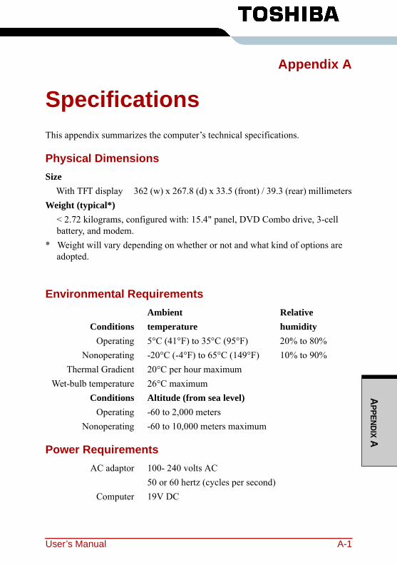
APPENDIX A
Appendix A
SpecificationsThis appendix summarizes the computer’s technical specifications.
Physical DimensionsSize
With TFT display 362 (w) x 267.8 (d) x 33.5 (front) / 39.3 (rear) millimetersWeight (typical*)
< 2.72 kilograms, configured with: 15.4" panel, DVD Combo drive, 3-cell battery, and modem.
* Weight will vary depending on whether or not and what kind of options are adopted.
Environmental RequirementsAmbient Relative
Conditions temperature humidityOperating 5°C (41°F) to 35°C (95°F) 20% to 80%
Nonoperating -20°C (-4°F) to 65°C (149°F) 10% to 90%Thermal Gradient 20°C per hour maximum
Wet-bulb temperature 26°C maximum Conditions Altitude (from sea level)
Operating -60 to 2,000 metersNonoperating -60 to 10,000 meters maximum
Power RequirementsAC adaptor 100- 240 volts AC
50 or 60 hertz (cycles per second)Computer 19V DC
User’s Manual A-1
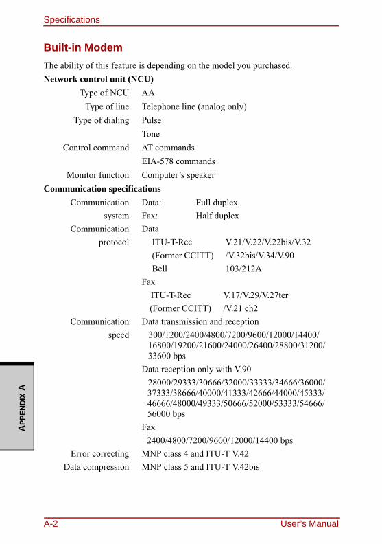
SpecificationsAP
PEND
IX A
Built-in ModemThe ability of this feature is depending on the model you purchased.Network control unit (NCU)
Type of NCU AAType of line Telephone line (analog only)
Type of dialing Pulse Tone
Control command AT commandsEIA-578 commands
Monitor function Computer’s speakerCommunication specifications
Communication Data: Full duplex system Fax: Half duplex
Communication Data protocol ITU-T-Rec V.21/V.22/V.22bis/V.32
(Former CCITT) /V.32bis/V.34/V.90Bell 103/212A
Fax ITU-T-Rec V.17/V.29/V.27ter(Former CCITT) /V.21 ch2
Communication Data transmission and reception speed 300/1200/2400/4800/7200/9600/12000/14400/
16800/19200/21600/24000/26400/28800/31200/33600 bps
Data reception only with V.9028000/29333/30666/32000/33333/34666/36000/37333/38666/40000/41333/42666/44000/45333/46666/48000/49333/50666/52000/53333/54666/56000 bps
Fax2400/4800/7200/9600/12000/14400 bps
Error correcting MNP class 4 and ITU-T V.42Data compression MNP class 5 and ITU-T V.42bis
A-2 User’s Manual
User’s Manual B-1
APPENDIX B
Appendix B
Display Controller and ModesDisplay controllerThe display controller interprets software commands into hardware commands that turn particular pels on or off.The controller is an advanced Video Graphics Array (VGA) that provides Super VGA (SVGA) and Extended Graphics Array (XGA) support for the internal LCD and external monitors. A high-resolution external monitor connected to the computer can display up to 2048 horizontal and 1536 vertical pixels at up to 16M colors.The display controller also controls the video mode, which uses industry stan-dard rules to govern the screen resolution and the maximum number of colors that can be displayed on screen.Software written for a given video mode will run on any computer that supports the mode.The computer’s display controller supports all SVGA and XGA modes, the most widely used industry standards.
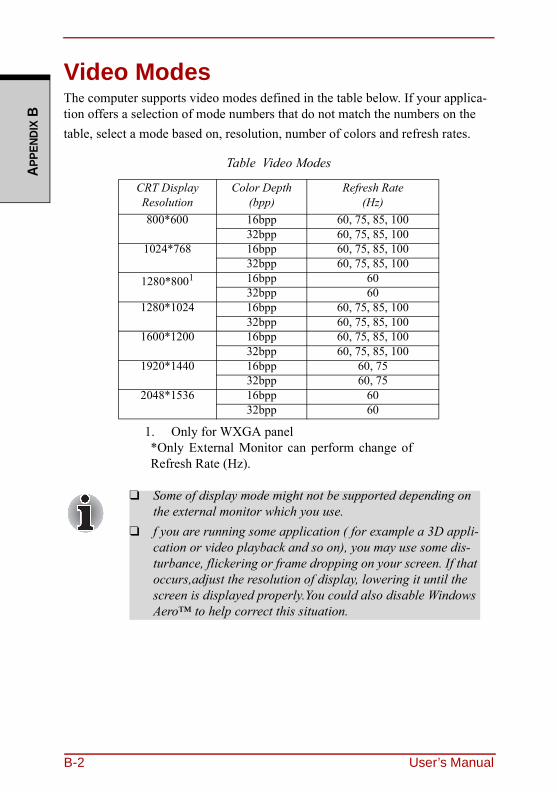
B-2 User’s Manual
APPE
NDIX
B
Video ModesThe computer supports video modes defined in the table below. If your applica-tion offers a selection of mode numbers that do not match the numbers on the table, select a mode based on, resolution, number of colors and refresh rates.
Table Video Modes
CRT Display Resolution
Color Depth(bpp)
Refresh Rate(Hz)
800*600 16bpp 60, 75, 85, 10032bpp 60, 75, 85, 100
1024*768 16bpp 60, 75, 85, 10032bpp 60, 75, 85, 100
1280*8001
1. Only for WXGA panel*Only External Monitor can perform change ofRefresh Rate (Hz).
16bpp 6032bpp 60
1280*1024 16bpp 60, 75, 85, 10032bpp 60, 75, 85, 100
1600*1200 16bpp 60, 75, 85, 10032bpp 60, 75, 85, 100
1920*1440 16bpp 60, 7532bpp 60, 75
2048*1536 16bpp 6032bpp 60
❑ Some of display mode might not be supported depending on the external monitor which you use.
❑ f you are running some application ( for example a 3D appli-cation or video playback and so on), you may use some dis-turbance, flickering or frame dropping on your screen. If that occurs,adjust the resolution of display, lowering it until the screen is displayed properly.You could also disable Windows Aero™ to help correct this situation.
User’s Manual C-1
APPENDIX C
Appendix C
V.90/V.92The TOSHIBA internal modem uses V.90 technology. The modem is capable of downstream speeds of 56Kbps (kilobits per second) when connected to an Inter-net service provider that supports V.90/V.92. As with any modem, the actual throughput (speed of data transfer) depends on analog telephone line conditions, which can vary considerably. Therefore, many users will experience throughput in the range of 32-44Kbps under normal telephone line conditions. Upstream data flows at the V.34 rate.
V.90/V.92 mode
V.90 rates can be achieved only when one V.90 capable modem is connected to another. The TOSHIBA Internal modem will select automatically V.34 if the remote modem lacks V.90 capability or if a combination of network and/or phone line conditions prevent V.90 connection.
Function Transmission speedData V.90/V.92 From 56K (maximum) to 28Kbps (minimum)
Reception only
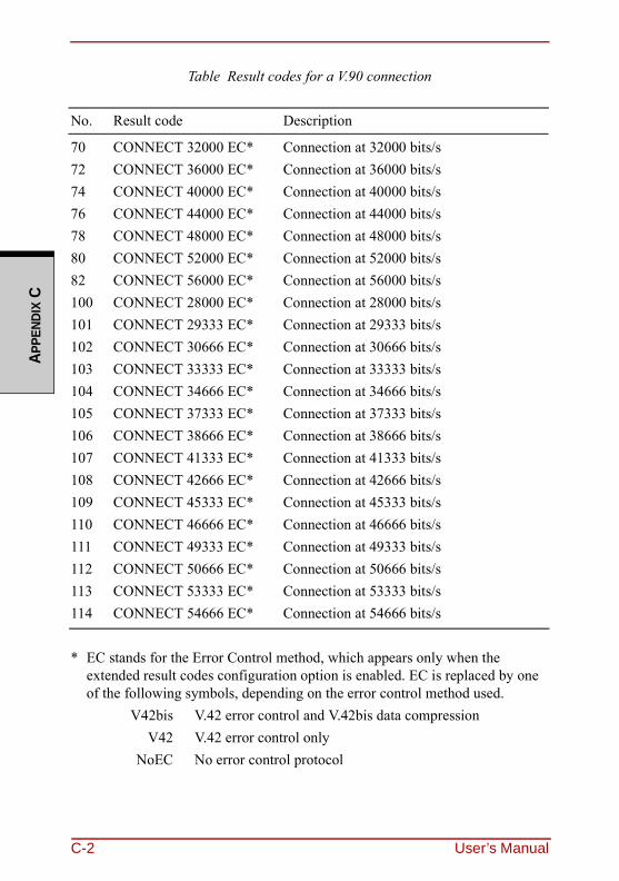
APPE
NDIX
C
Table Result codes for a V.90 connection
No. Result code Description
70 CONNECT 32000 EC* Connection at 32000 bits/s72 CONNECT 36000 EC* Connection at 36000 bits/s74 CONNECT 40000 EC* Connection at 40000 bits/s76 CONNECT 44000 EC* Connection at 44000 bits/s78 CONNECT 48000 EC* Connection at 48000 bits/s80 CONNECT 52000 EC* Connection at 52000 bits/s82 CONNECT 56000 EC* Connection at 56000 bits/s100 CONNECT 28000 EC* Connection at 28000 bits/s101 CONNECT 29333 EC* Connection at 29333 bits/s102 CONNECT 30666 EC* Connection at 30666 bits/s103 CONNECT 33333 EC* Connection at 33333 bits/s104 CONNECT 34666 EC* Connection at 34666 bits/s105 CONNECT 37333 EC* Connection at 37333 bits/s106 CONNECT 38666 EC* Connection at 38666 bits/s107 CONNECT 41333 EC* Connection at 41333 bits/s108 CONNECT 42666 EC* Connection at 42666 bits/s109 CONNECT 45333 EC* Connection at 45333 bits/s110 CONNECT 46666 EC* Connection at 46666 bits/s111 CONNECT 49333 EC* Connection at 49333 bits/s112 CONNECT 50666 EC* Connection at 50666 bits/s113 CONNECT 53333 EC* Connection at 53333 bits/s114 CONNECT 54666 EC* Connection at 54666 bits/s
* EC stands for the Error Control method, which appears only when the extended result codes configuration option is enabled. EC is replaced by one of the following symbols, depending on the error control method used.
V42bis V.42 error control and V.42bis data compressionV42 V.42 error control only
NoEC No error control protocol
C-2 User’s Manual
APPENDIX C
AT Command-V90=* V.90 Dial Line Rate
-V90 sets the maximum V.90 downstream that the modem attempts to connect.
-V90=0 V.90 disabled-V90=1 V.90 enabled: automatic speed selection - maximum modem speed
(default)
User’s Manual C-3

APPE
NDIX
C
C-4 User’s Manual
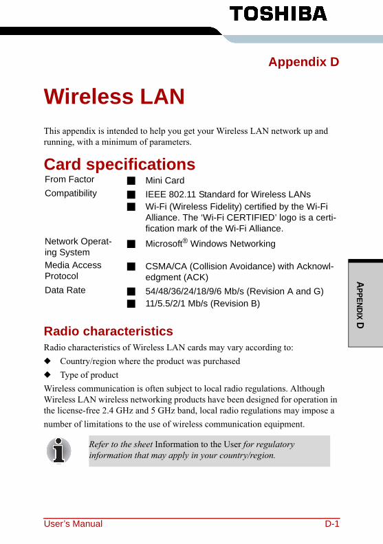
APPENDIX D
Appendix D
Wireless LANThis appendix is intended to help you get your Wireless LAN network up and running, with a minimum of parameters.
Card specifications
Radio characteristicsRadio characteristics of Wireless LAN cards may vary according to:◆ Country/region where the product was purchased◆ Type of productWireless communication is often subject to local radio regulations. Although Wireless LAN wireless networking products have been designed for operation in the license-free 2.4 GHz and 5 GHz band, local radio regulations may impose a number of limitations to the use of wireless communication equipment.
From Factor ■ Mini CardCompatibility ■ IEEE 802.11 Standard for Wireless LANs
■ Wi-Fi (Wireless Fidelity) certified by the Wi-Fi Alliance. The ‘Wi-Fi CERTIFIED’ logo is a certi-fication mark of the Wi-Fi Alliance.
Network Operat-ing System
■ Microsoft® Windows Networking
Media Access Protocol
■ CSMA/CA (Collision Avoidance) with Acknowl-edgment (ACK)
Data Rate ■ 54/48/36/24/18/9/6 Mb/s (Revision A and G)■ 11/5.5/2/1 Mb/s (Revision B)
Refer to the sheet Information to the User for regulatory information that may apply in your country/region.
User’s Manual D-1
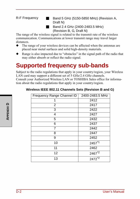
APPE
NDIX
D
The range of the wireless signal is related to the transmit rate of the wireless communication. Communications at lower transmit range may travel larger distances.◆ The range of your wireless devices can be affected when the antennas are
placed near metal surfaces and solid high-density materials.◆ Range is also impacted due to “obstacles” in the signal path of the radio that
may either absorb or reflect the radio signal.
Supported frequency sub-bandsSubject to the radio regulations that apply in your country/region, your Wireless LAN card may support a different set of 5 GHz/2.4 GHz channels.Consult your Authorized Wireless LAN or TOSHIBA Sales office for informa-tion about the radio regulations that apply in your country/region.
Wireless IEEE 802.11 Channels Sets (Revision B and G)
R-F Frequency ■ Band 5 GHz (5150-5850 MHz) (Revision A, Draft N)
■ Band 2.4 GHz (2400-2483.5 MHz)(Revision B, G, Draft N)
Frequency Range Channel ID 2400-2483.5 MHz1 24122 24173 24224 24275 24326 24377 24428 24479 245210 2457*1
11 246212 2467*2
13 2472*2
D-2 User’s Manual
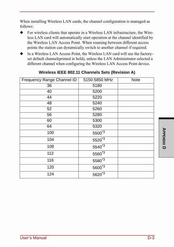
APPENDIX D
When installing Wireless LAN cards, the channel configuration is managed as follows:◆ For wireless clients that operate in a Wireless LAN infrastructure, the Wire-
less LAN card will automatically start operation at the channel identified by the Wireless LAN Access Point. When roaming between different access points the station can dynamically switch to another channel if required.
◆ In a Wireless LAN Access Point, the Wireless LAN card will use the factory-set default channel(printed in bold), unless the LAN Administrator selected a different channel when configuring the Wireless LAN Access Point device.
Wireless IEEE 802.11 Channels Sets (Revision A)
Frequency Range Channel ID 5150-5850 MHz Note36 518040 520044 522048 524052 526056 528060 530064 5320100 5500*3
104 5520*3
108 5540*3
112 5560*3
116 5580*3
120 5600*3
124 5620*3
User’s Manual D-3
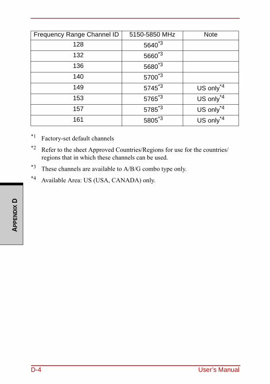
APPE
NDIX
D
*1 Factory-set default channels*2 Refer to the sheet Approved Countries/Regions for use for the countries/
regions that in which these channels can be used.*3 These channels are available to A/B/G combo type only.*4 Available Area: US (USA, CANADA) only.
Frequency Range Channel ID 5150-5850 MHz Note128 5640*3
132 5660*3
136 5680*3
140 5700*3
149 5745*3 US only*4
153 5765*3 US only*4
157 5785*3 US only*4
161 5805*3 US only*4
D-4 User’s Manual
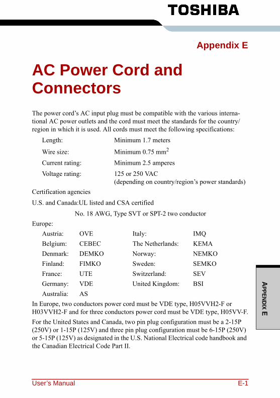
APPENDIX E
Appendix E
AC Power Cord and ConnectorsThe power cord’s AC input plug must be compatible with the various interna-tional AC power outlets and the cord must meet the standards for the country/region in which it is used. All cords must meet the following specifications:
Length: Minimum 1.7 meters
Wire size: Minimum 0.75 mm2
Current rating: Minimum 2.5 amperesVoltage rating: 125 or 250 VAC
(depending on country/region’s power standards)Certification agenciesU.S. and Canada:UL listed and CSA certified
No. 18 AWG, Type SVT or SPT-2 two conductorEurope:
Austria: OVE Italy: IMQBelgium: CEBEC The Netherlands: KEMADenmark: DEMKO Norway: NEMKOFinland: FIMKO Sweden: SEMKOFrance: UTE Switzerland: SEVGermany: VDE United Kingdom: BSIAustralia: AS
In Europe, two conductors power cord must be VDE type, H05VVH2-F or H03VVH2-F and for three conductors power cord must be VDE type, H05VV-F.For the United States and Canada, two pin plug configuration must be a 2-15P (250V) or 1-15P (125V) and three pin plug configuration must be 6-15P (250V) or 5-15P (125V) as designated in the U.S. National Electrical code handbook and the Canadian Electrical Code Part II.
User’s Manual E-1
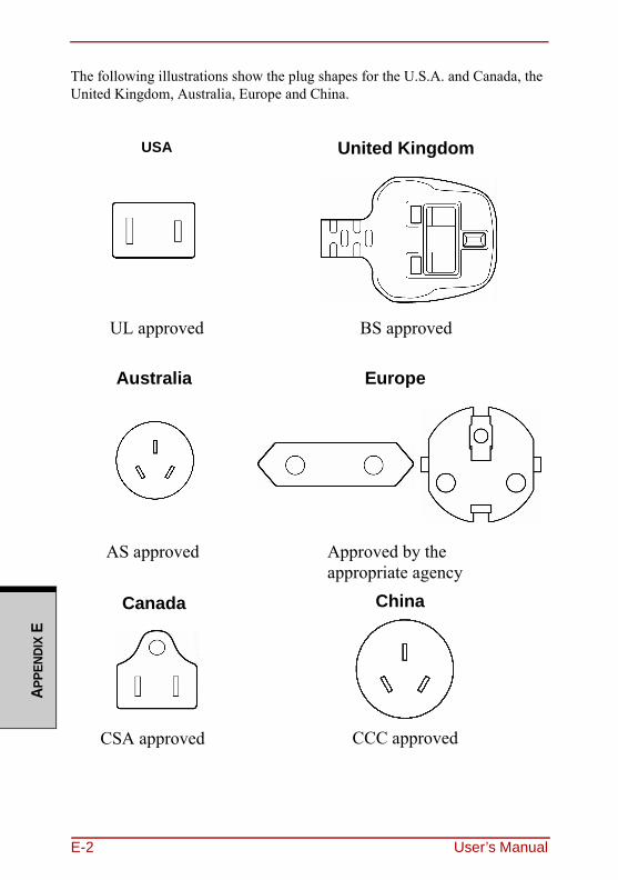
APPE
NDIX
E
The following illustrations show the plug shapes for the U.S.A. and Canada, the United Kingdom, Australia, Europe and China.
USA United Kingdom
UL approved BS approved
Australia Europe
AS approved Approved by the appropriate agency
Canada
CSA approved
China
CCC approved
E-2 User’s Manual
User’s Manual Glossary-1
GLO
SSARY
GlossaryThe terms in this glossary cover the topics discussed in this manual. Alternate naming is included for reference.
AbbreviationsAC: alternating currentAGP: accelerated graphics portANSI: American National Standards InstituteAPM: advanced power managerASCII: American Standard Code for Information InterchangeBIOS: basic input output systemCMOS: complementary metal-oxide semiconductorCPU: central processing unitCRT: cathode ray tubeCSV: Clear Super ViewDC: direct currentDDC: display data channelDOS: disk operating systemDMA: direct memory accessDRAM: dynamic random access memoryDSVD: Digital Simultaneous Voice and DataDVD: Digital Versatile DiscDVI: Digital Visual InterfaceECP: extended capabilities portEGA: enhanced graphics adapter
FDD: floppy disk driveFIR: fast infraredHDD: hard disk driveIDE: integrated drive electronicsI/O: input/outputIrDA: Infrared Data AssociationIRQ: interrupt requestKB: kilobyteLCD: liquid crystal displayLED: light emitting diodeLSI: large scale integrationMDA: monochrome display adapterMPEG: moving picture coding experts groupMS-DOS: Microsoft Disk Operating SystemOCR: optical character recognition (reader)PCB: printed circuit boardPCI: peripheral component intercon-nectPCMCIA: Personal Computer Mem-ory Card International Association RAM: random access memoryRGB: red, green, and blueROM: read only memory
GLO
SSAR
Y
SCSI(Abbreviations continued)SCSI: small computer system inter-faceSIO: serial input/outputSO-DIMM: small-outline dual in-line memory moduleSVGA: super video graphics adapterSDRAM: synchronized dynamic ran-dom access memoryTFT: thin-film transistorUART: universal asynchronous receiver/transmitterUSB: Universal Serial BusVESA: Video Electronic Standards AssociationVGA: video graphics array VRM: video ready modemVRT: voltage reduction technology
Aadapter: A device that provides an interface between two dissimilar elec-tronic devices. For example, the AC adapter modifies the power from a wall outlet for use by the computer. This term also refers to the add-in cir-cuit cards that control external devices, such as video monitors and magnetic tape devices. allocate: To assign a space or function for a specific task.alphanumeric: Keyboard characters including letters, numbers and other symbols, such as punctuation marks or mathematical symbols.
alternating current (AC): Electric current that reverses its direction of flow at regular intervals. analog signal: A signal whose charac-teristics such as amplitude and fre-quency vary in proportion to (are an analog of) the value to be transmitted. Voice communications are analog sig-nals.ANSI: American National Standards Institute. An organization established to adopt and define standards for a variety of technical disciplines. For example, ANSI defined the ASCII standard and other information pro-cessing requirements.antistatic: A material used to prevent the buildup of static electricity.application: A group of programs that together are used for a specific task such as accounting, financial planning, spreadsheets, word processing, and games, etc.ASCII: American Standard Code for Information Interchange. ASCII code is a set of 256 binary codes that repre-sent the most commonly used letters, numbers, and symbols.async: Short for asynchronous.asynchronous: Lacking regular time relationship. As applied to computer communications, asynchronous refers to the method of transmitting data that does not require a steady stream of bits to be transmitted at regular time inter-vals.
Glossary-2 User’s Manual
GLO
SSARY
AUTOEXEC.BAT: A batch file that executes a series of MS-DOS com-mands and programs each time you start the computer.
Bbackup: A duplicate copy of files kept as a spare in case the original is destroyed.batch file: A file that can be executed from the system prompt containing a sequence of operating system com-mands or executable files. See also AUTOEXEC.BAT.binary: The base two number system composed of zeros and ones (off or on), used by most digital computers. The right most digit of a binary num-ber has a value of 1, the next a value of 2, then 4, 8, 16, and so on. For exam-ple, the binary number 101 has a value of 5. See also ASCII.BIOS: Basic Input Output System. The firmware that controls data flow within the computer. See also firm-ware.bit: Derived from ģbinary digit,ī the basic unit of information used by the computer. It is either zero or one. Eight bits is one byte. See also byte.
Byte
Bluetooth: A short-range radio tech-nology designed to simplify wireless communication among computers, communication devices and the Inter-net.board: A circuit board. An internal card containing electronic compo-nents, called chips, which perform a specific function or increase the capa-bilities of the system.boot: Short for bootstrap. A program that starts or restarts the computer. The program reads instructions from a stor-age device into the computer’s mem-ory.bps: Bits per second. Typically used to describe the data transmission speed of a modem.buffer: The portion of the computer’s memory where data is temporarily stored. Buffers often compensate for differences in the rate of flow from one device to another.bus: An interface for transmission of signals, data or electric power.byte: The representation of a single character. A sequence of eight bits treated as a single unit; also the small-est addressable unit within the system.
User’s Manual Glossary-3
GLO
SSAR
Y
cache memoryCcache memory: High speed memory which stores data that increases pro-cessor speed and data transfer rate. When the CPU reads data from main memory, it stores a copy of this data in cache memory. The next time the CPU needs that same data, it looks for it in the cache memory rather than the main memory, which saves time. The com-puter has two cache levels. Level one is incorporated into the processor and level two resides in external memory.card: Synonym for board. See board.CardBus: An industry standard bus for 32-bit PC Cards.capacity: The amount of data that can be stored on a magnetic storage device such as a diskette (floppy disk) or hard disk. It is usually described in terms of kilobytes (KB), where one KB = 1024 bytes and megabytes (MB), where one MB = 1024 KB.CD-ROM: A Compact Disk-Read Only Memory is a high capacity disk that can be read from but not written to. The CD-ROM drive uses a laser, rather than magnetic heads, to read data from the disk.Centronics: The printer manufacturer whose method of data transmission between a parallel printer and a com-puter has become an industry standard.
CGA: Color/graphics adapter. A video display protocol defined by the IBM Color/Graphics Monitor Adapter and its associated circuitry. This protocol supports two-color 640x200 and four-color 320x200 graphics, and 16-color 640x200 and 320x200 text modes.character: Any letter, number, punc-tuation mark, or symbol used by the computer. Also synonymous with byte.chassis: The frame containing the computer.chip: A small semiconductor contain-ing computer logic and circuitry for processing, memory, input/output functions and controlling other chips.Circle Surround Xtract: a technol-ogy that develops the multichannel sound source compressed into the ste-reo by the Circle Surround form, and reproduces the surround by TruSur-round XT. CMOS: Complementary Metal-Oxide Semiconductor. An electronic circuit fabricated on a silicon wafer that requires very little power. Integrated circuits implemented in CMOS tech-nology can be tightly packaged and are highly reliable.cold start: Starting a computer that is currently off (turning on the power).COM1, COM2, COM3 and COM4: The names assigned to the serial and communication ports.commands: Instructions you enter at the terminal keyboard that direct the actions of the computer or its periph-eral devices.
Glossary-4 User’s Manual
GLO
SSARY
communications: The means by which a computer transmits and receives data to and from another com-puter or device. See parallel interface; serial interface.compatibility: 1) The ability of one computer to accept and process data in the same manner as another computer without modifying the data or the media upon which it is being trans-ferred. 2) the ability of one device to connect to or communicate with another system or component.components: Elements or parts (of a system) which make up the whole (system).computer program: A set of instruc-tions written for a computer that enable it to achieve a desired result.computer system: A combination of hardware, software, firmware, and peripheral components assembled to process data into useful information.configuration: The specific compo-nents in your system (such as the ter-minal, printer, and disk drives) and the settings that define how your system works. You use the Hardware Setup, MaxTime or HW Setup program to control your system configuration.control keys: A key or sequence of keys you enter from the keyboard to initiate a particular function within a program.controller: Built-in hardware and soft-ware that controls the functions of a specific internal or peripheral device (e.g. keyboard controller).
Definition
co-processor: A circuit built into the processor that is dedicated to intensive math calculations.CPS: Characters per second. Typically used to indicate the transmission speed of a printer.CPU: Central processing unit. The portion of the computer that interprets and executes instructions.CRT: Cathode Ray Tube. A vacuum tube in which beams projected on a fluorescent screen-producing luminous spots. An example is the television set.cursor: A small, blinking rectangle or line that indicates the current position on the display screen.
Ddata: Information that is factual, mea-surable or statistical that a computer can process, store, or retrieve.data bits: A data communications parameter controlling the number of bits (binary digits) used to make up a byte. If data bits = 7 the computer can generate 128 unique characters. If data bits = 8 the computer can generate 256 unique characters.DC: Direct Current. Electric current that flows in one direction. This type of power is usually supplied by batter-ies.default: The parameter value automat-ically selected by the system when you or the program do not provide instruc-tions. Also called a preset value.Definition: one of functions that increase clearness of sounds.
User’s Manual Glossary-5
GLO
SSAR
Y
deletedelete: To remove data from a disk or other data storage device. Synonymous with erase.device driver: A program that con-trols communication between a spe-cific peripheral device and the computer. The CONFIG.SYS file con-tains device drivers that MS-DOS loads when you turn the computer on.dialog box: A window that accepts user input to make system settings or record other information.disk drive: The device that randomly accesses information on a disk and copies it to the computer’s memory. It also writes data from memory to the disk. To accomplish these tasks, the unit physically rotates the disk at high speed past a read-write head.disk storage: Storing data on mag-netic disk. Data is arranged on concen-tric tracks much like a phonograph record.diskette: A removable disk that stores magnetically encoded data used on a microcomputer. Also called floppy disk.diskette drive: An electromechanical device that reads and writes to floppy disks. See also diskette.display: A CRT, plasma screen, LCD, or other image producing device used to view computer output.
documentation: The set of manual and/or other instructions written for the users of a computer system or application. Computer system docu-mentation typically includes proce-dural and tutorial information as well as system functions.
DOS: Disk operating system. See operating system.driver: A software program, generally part of the operating system, that con-trols a specific piece of hardware (fre-quently a peripheral device such as a printer or mouse).
Eecho: To send back a reflection of the transmitted data to the sending device. You can display the information on the screen, or output it to the printer, or both. When a computer receives back data it transmitted to a CRT (or other peripheral device) and then retransmits the data to the printer, the printer is said to echo the CRT.EGA: Enhanced Graphics Adapter. A video display protocol defined by the IBM Enhanced Graphics Adapter and its associated circuitry for direct drive TTL displays that supports 16-color/monochrome 640x350 and 16-color 640x200 and 320x200 graphics, and 16-color 640x350 and 320x350 text modes.erase: See delete.
Glossary-6 User’s Manual
GLO
SSARY
escape: 1) A code (ASCII code 27), signaling the computer that what fol-lows are commands; used with periph-eral devices such as printers and modems. 2) A means of aborting the task currently in progress.escape guard time: A time before and after an escape code is sent to the modem which distinguishes between escapes that are part of the transmitted data, and escapes that are intended as a command to the modem.execute: To interpret and execute an instruction.Extended Capability Port: An indus-try standard that provides a data buffer, switchable forward and reverse data transmission, and run length encoding (RLE) support.
Ffast infrared: An industry standard that enables cableless infrared serial data transfer at speeds of up to 4 Mbps. file: A collection of related informa-tion; a file can contain data, programs, or both.firmware: A set of instructions built into the hardware which controls and directs a microprocessor’s activities.fixed disk: See hard disk.floppy disk: See diskette.floppy disk drive (FDD): See diskette drive.
hertz
format: The process of readying a blank disk for its first use. Formatting establishes the structure of the disk that the operating system expects before it writes files or programs onto the disk.folder: An icon in Windows used to store documents or other folders.function keys: The keys labeled F1 through F12 that tell the computer to perform certain functions.
Ggigabyte (GB): A unit of data storage equal to 1024 megabytes. See also megabyte.GND: Ground. An RS-232C signal used in the exchange of data between a computer and serial device.graphics: The use of drawings, pic-tures, or other images, such as charts or graphs, to present information.
Hhard disk: A non-removable disk usu-ally referred to as drive C. Also called fixed disk.hard disk drive (HDD): An electro-mechanical device that reads and writes a hard disk. See also hard disk.hardware: The physical electronic and mechanical components of a com-puter system: typically, the computer itself, external disk drives, etc. See also software and firmware.hertz: A unit of wave frequency that equals one cycle per second.
User’s Manual Glossary-7
GLO
SSAR
Y
hexadecimalhexadecimal: The base 16 numbering system composed of the digits 0 through 9 and the letters A, B, C, D, E, and F.host computer: The computer that controls, regulates, and transmits information to a device or another computer.hot dock/undock: Connecting or dis-connecting a device to or from the computer while the computer’s power is turned on.hot key: The computer’s feature in which certain keys in combination with the extended function key, FN, can be used to set system parameters, such as speaker volume.HW Setup: A TOSHIBA utility that lets you set the parameters for various hardware components.
Iicon: A small graphic image displayed on the screen or in the indicator panel. In Windows, an icon represents an object that the user can manipulate.iLINK (IEEE1394): This port enables high-speed data transfer directly from external devices such as digital video cameras.
input: The data or instructions you provide to a computer, communica-tion device or other peripheral device from the keyboard or external or inter-nal storage devices. The data sent (or output) by the sending computer is input for the receiving computer.instruction: Statements or commands that specify how to perform a particu-lar task.interface: 1) Hardware and/or soft-ware components of a system used specifically to connect one system or device to another. 2) To physically connect one system or device to another to exchange information. 3) The point of contact between user, the computer, and the program, for exam-ple, the keyboard or a menu.interrupt request: A signal that gives a component access to the processor.I/O: Input/output. Refers to accep-tance and transfer of data to and from a computer.I/O devices: Equipment used to com-municate with the computer and trans-fer data to and from it.
Jjumper: A small clip or wire that allows you to change the hardware characteristics by electrically connect-ing two points of a circuit.
KK: Taken from the Greek word kilo, meaning 1000; often used as equiva-lent to 1024, or 2 raised to the 10th power. See also byte and kilobyte.
Glossary-8 User’s Manual
GLO
SSARY
KB: See kilobyte.keyboard: An input device contain-ing switches that are activated by man-ually pressing marked keys. Each keystroke activates a switch that trans-mits a specific code to the computer. For each key, the transmitted code is, in turn, representative of the (ASCII) character marked on the key.kilobyte (KB): A unit of data storage equal to 1024 bytes. See also byte and megabit.Llevel 2 cache: See cache.Light Emitting Diode (LED): A semiconductor device that emits light when a current is applied.Liquid Crystal Display (LCD): Liq-uid crystal sealed between two sheets of glass coated with transparent con-ducting material. The viewing-side coating is etched into character form-ing segments with leads that extend to the edge of the glass. Applying a volt-age between the glass sheets darkens the liquid crystal to provide contrast to lighted portions of the display.LSI: Large Scale Integration. 1) A technology that allows the inclusion of up to 100,000 simple logic gates on a single chip. 2) An integrated circuit that uses the large scale integration.
modem
Mmain board: See motherboard.MDA: Monochrome Display Adapter. A video display protocol defined by the IBM Monochrome Display Adapter and its associated circuitry for direct drive TTL displays that supports a monochrome 720x350 text mode.megabyte (MB): A unit of data stor-age equal to 1024 kilobytes. See also kilobyte.megahertz: A unit of wave frequency that equals 1 million cycles per second. See also hertz.menu: A software interface that dis-plays a list of options on the screen. Also called a screen.microprocessor: A hardware compo-nent contained in a single integrated circuit that carries out instructions. Also called the central processing unit (CPU), one of the main parts of the computer.MMX: Refers to microprocessors with additional instructions beyond the x86 standard. The instructions were devel-oped on the basis of multimedia code requirements and thus improve the performance of multimedia applica-tions.mode: A method of operation, for example, the boot mode or the resume mode.modem: Derived from modulator/demodulator, a device that converts (modulates) digital data for transmis-sion over telephone lines and then con-verts modulated data (demodulates) to digital format where received.
User’s Manual Glossary-9
GLO
SSAR
Y
monitormonitor: A device that uses rows and columns of pixels to display alphanu-meric characters or graphic images. See CRT.motherboard: A name sometimes used to refer to the main printed circuit board in processing equipment. It usu-ally contains integrated circuits that perform the processor’s basic func-tions and provides connectors for add-ing other boards that perform special functions. Sometimes called a main board.MPEG: Moving picture coding expert group is an industry standard architec-ture for compression of video signals.
Nnon-system disk: A formatted diskette (floppy disk) you can use to store pro-grams and data but you cannot use to start the computer. See system disk.nonvolatile memory: Memory, usu-ally read-only (ROM), that is capable of permanently storing information. Turning the computer’s power off does not alter data stored in nonvolatile memory.numeric keypad overlay: A feature that allows you to use certain keys on the keyboard to perform numeric entry, or to control cursor and page move-ment.
OOCR: Optical Character Recognition (reader). A technique or device that uses laser or visible light to identify characters and input them into a stor-age device.OCR wand: A device that reads, using an optical device, hand written or machine printed symbols into a com-puter. See also OCR.on-line state: A functional state of a peripheral device when it is ready to receive or transmit data.operating system: A group of pro-grams that controls the basic operation of a computer. Operating system func-tions include interpreting programs, creating data files, and controlling the transmission and receipt (input/output) of data to and from memory and peripheral devices.output: The results of a computer operation. Output commonly indicates data 1) printed on paper, 2) displayed at a terminal, 3) sent through the serial port of internal modem, or 4) stored on some magnetic media.
Pparallel: Refers to two or more pro-cesses or events that can occur simul-taneously, and without interfering with each other. See also serial.parallel interface: Refers to a type of information exchange that transmits information one byte (8 bits) at a time. See also serial interface.
Glossary-10 User’s Manual
GLO
SSARY
parity: 1) The symmetrical relation-ship between two parameter values (integers) both of which are either on or off; odd or even; 0 or 1. 2) In serial communications, an error detection bit that is added to a group of data bits making the sum of the bits even or odd. Parity can be set to none, odd, or even.password: A unique string of charac-ters used to identify a specific user. The computer provides various levels of password protection such as user, supervisor and eject.pel: The smallest area of the display that can be addressed by software. Equal in size to a pixel or group of pix-els. See pixel.peripheral component interconnect: An industry standard 32-bit bus.peripheral device: An I/O device that is external to the central processor and/or main memory such as a printer or a mouse.plug and play: A capability with Win-dows that enables the system to auto-matically recognize connections of external devices and make the neces-sary configurations in the computer.pixel: A picture element. The smallest dot that can be made on a display or printer. Also called a pel.port: The electrical connection through which the computer sends and receives data to and from devices or other computers.
RAM
Port Replicator: Devices that enables one-point connection to a number of peripheral devices and provides addi-tional ports and slots. printed circuit board (PCB): A hard-ware component of a processor to which integrated circuits and other components are attached. The board itself is typically flat and rectangular, and constructed of fiberglass, to form the attachment surface.program: A set of instructions a com-puter can execute that enables it to achieve a desired result. See also appli-cation.prompt: A message the computer pro-vides indicating it is ready for or requires information or an action from you.
RRadio frequency interference (RFI) shield: A metal shield enclosing the printed circuit boards of the printer or computer to prevent radio and TV interference. All computer equipment generates radio frequency signals. The FCC regulates the amount of signals a computing device can allow past its shielding. A Class A device is suffi-cient for office use. Class B provides a more stringent classification for home equipment use. TOSHIBA portable computers comply with Class B com-puting device regulations.Random Access Memory (RAM): High speed memory within the com-puter circuitry that can be read or writ-ten to.
User’s Manual Glossary-11
GLO
SSAR
Y
restartrestart: Resetting a computer without turning it off (also called ‘warm boot’ or ‘soft reset’). To restart the computer, press CTRL + ALT + DEL while the computer is on. See also boot.RCA jack: A single-pin connector that carries composite video signals, which include both contrast and color information. See also S-video.RGB: Red, green, and blue. A device that uses three input signals, each acti-vating an electron gun for a primary additive color (red, green, and blue) or port for using such a device. See also CRT.RJ11: A modular telephone jack.ROM: Read Only Memory: A nonvol-atile memory chip manufactured to contain information that controls the computer’s basic operation. You can-not access or change information stored in ROM.RS-232C: The Electronic Industries Association (EIA) interface standard that describes the 25-pin connector interface and control, data, and status signals that allow asynchronous com-munications between computers, print-ers, communications and other peripheral devices.
SSCSI: Small Computer System Inter-face is an industry standard interface for connection of a variety of periph-eral devices.
serial: The handling of data bits one after the other.serial communications: A communi-cations technique that uses as few as two interconnecting wires to send bits one after another.serial interface: Refers to a type of information exchange that transmits information sequentially, one bit at a time. Contrast: Parallel interface.serial port: A communications port to which you can connect devices, such as a modem, mouse, or serial printer.SIO: Serial Input/Output. The elec-tronic methodology used in serial data transmission.soft key: Key combinations that emu-late keys on the IBM keyboard, change some configuration options, stop pro-gram execution, and access the numeric keypad overlay.software: The set of programs, proce-dures and related documentation asso-ciated with a computer system. Specifically refers to computer pro-grams that direct and control the com-puter system’s activities. See also hardware.stop bit: One or more bits of a byte that follow the transmitted character or group codes in asynchronous serial communications.subpixel: Three elements, one red, one green and blue (RGB), that make up a pixel on the color LCD. The computer sets subpixels independently, each may emit a different degree of brightness. See also pixel.
Glossary-12 User’s Manual
GLO
SSARY
S-video: This connection provides separate lines for contrast and color, which produces a video image superior to that produced by a composite con-nection. See also RCA jack.synchronous: Having a constant time interval between successive bits, char-acters or events.system disk: A disk that has been for-matted with an operating system. For MS-DOS the operating system is con-tained in two hidden files and the COMMAND.COM file. You can boot a computer using a system disk. Also called an operating system disk.
Tterminal: A typewriter-like keyboard and CRT display screen connected to the computer for data input/output.TFT: A color LCD technology that applies individual transistors to each pixel enabling fine display control and excellent screen legibility.TTL: Transistor-transistor logic. A logic circuit design that uses switching transistors for gates and storage.
UUSB: Enables chain connection of a number of USB-equipped devices to one port on your computer. For exam-ple, you might connect a USB-HUB to the computer, then connect a keyboard to the USB-HUB and a mouse to the keyboard.
write protection
VVGA: Video graphics array is an industry standard video adapter that lets you run any popular software.volatile memory: Random access memory (RAM) that stores informa-tion as long as the computer is con-nected to a power source.
WWarm dock/undock: Connecting or disconnecting a device to or from the computer while the computer is sus-pended.warm start: Restarting or resetting a computer without turning it off.window: A portion of the screen that can display its own application or doc-ument. Often used to mean a Microsoft® Windows window.Wireless LAN: A short-range radio technology designed to simplify wire-less communication with other LAN systems based on Direct Sequence Spread Spectrum radio technology that complies with the IEEE 802.11 Stan-dard (Revision B).write protection: A method for pro-tecting a diskette (floppy disk) from accidental erasure.
User’s Manual Glossary-13

GLO
SSAR
Y
Glossary-14 User’s Manual
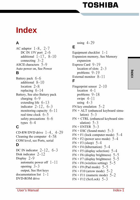
INDEX
IndexAAC adaptor 1-8, 2-7
DC IN 15V port 2-6additional 1-17, 8-10connecting 3-2
ASCII characters 5-9Auto power on, See PowerBBattery pack 6-6
additional 8-10location 2-8replacing 6-14
Battery, See also Battery packcharging 6-9extending life 6-13indicator 2-12, 6-3monitoring capacity 6-11real time clock 6-5safety precautions 6-6types 6-4
CCD-RW/DVD drive 1-4, 4-29Cleaning the computer 4-58COM level, see Ports, serialDDC IN indicator 2-12, 6-3Disk indicator 2-12Display 2-9
automatic power off 1-11opening 3-3output, See Hot keys
documentation list 1-1DVD-ROM drive
using 4-29EEquipment checklist 1-1Expansion memory, See Memory
expansionExpress Card 9-19
location of slots 2-3problems 9-19
External monitor 8-11FFingerprint sensor 2-10
location 4-1problems 9-18swipe 4-11using 4-3
FN key emulation 5-2FN + ALT (enhanced keyboard simu-
lation) 5-3FN + CTRL (enhanced keyboard sim-
ulation) 5-3FN + ENTER 5-3FN + ESC (Sound mute) 5-3FN + F1 (lock computer mode) 5-4FN + F2 (power save mode) 5-4FN + F3 (sleep) 5-4FN + F4 (hibernation) 5-4FN + F5 (display selection) 5-4FN + F6 (display brightness) 5-5FN + F7 (display brightness) 5-5FN + F8 (wireless setting) 5-5FN + F9 (Pad mode) 5-5FN + F10 (arrow mode) 5-2FN + F11 (numeric mode) 5-2FN + F12 (ScrLock) 5-3
User’s Manual Index-1
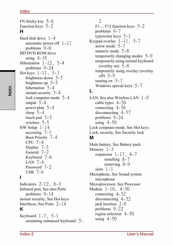
IndexIN
DEX
FN Sticky key 5-6Function keys 5-2HHard disk drive 1-4
automatic power off 1-11problems 9-8
HD DVD-ROM driveusing 4-35
Hibernation 1-12, 5-4problems 9-24
Hot keys 1-11, 5-3brightness down 5-5brightness up 5-5hibernation 5-4instant security 5-4lock computer mode 5-4output 5-4power plan 5-4sleep 5-4touch pad 5-5wireless 5-5
HW Setup 1-14accessing 7-1Boot Priority 7-4CPU 7-4Display 7-3General 7-2Keyboard 7-6LAN 7-6Password 7-2USB 7-6
IIndicators 2-12, 6-3Infrared port, See also Ports
problems 9-14instant security, See Hot keysInterfaces, See Ports 2-14KKeyboard 1-7, 5-1
emulating enhanced keyboard 5-
2F1 ... F12 function keys 5-2problems 9-7typewriter keys 5-1
Keypad overlay 1-11, 5-7arrow mode 5-7numeric mode 5-8temporarily changing modes 5-9temporarily using normal keyboard
(overlay on) 5-8temporarily using overlay (overlay
off) 5-9turning on 5-7Windows special keys 5-7
LLAN, See also Wireless LAN 1-9
cable types 4-56connecting 4-56disconnecting 4-57problems 9-24using 4-56
Lock computer mode, See Hot keysLock, security, See Security lockMMain battery, See Battery packMemory 1-3
expansion 1-17, 8-7installing 8-7removing 8-9
slots 1-3Microphone, See Sound system
microphoneMicroprocessor, See ProcessorModem 1-10, 4-50
connecting 4-52disconnecting 4-52jack location 2-6problems 9-22region selection 4-50using 4-50
Index-2 User’s Manual
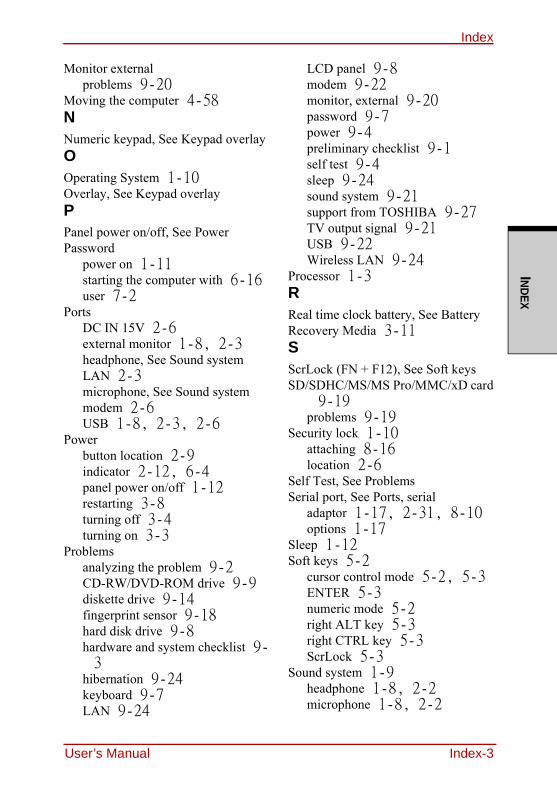
IndexINDEX
Monitor externalproblems 9-20
Moving the computer 4-58NNumeric keypad, See Keypad overlayOOperating System 1-10Overlay, See Keypad overlayPPanel power on/off, See PowerPassword
power on 1-11starting the computer with 6-16user 7-2
PortsDC IN 15V 2-6external monitor 1-8, 2-3headphone, See Sound systemLAN 2-3microphone, See Sound systemmodem 2-6USB 1-8, 2-3, 2-6
Powerbutton location 2-9indicator 2-12, 6-4panel power on/off 1-12restarting 3-8turning off 3-4turning on 3-3
Problemsanalyzing the problem 9-2CD-RW/DVD-ROM drive 9-9diskette drive 9-14fingerprint sensor 9-18hard disk drive 9-8hardware and system checklist 9-3
hibernation 9-24keyboard 9-7LAN 9-24
LCD panel 9-8modem 9-22monitor, external 9-20password 9-7power 9-4preliminary checklist 9-1self test 9-4sleep 9-24sound system 9-21support from TOSHIBA 9-27TV output signal 9-21USB 9-22Wireless LAN 9-24
Processor 1-3RReal time clock battery, See BatteryRecovery Media 3-11SScrLock (FN + F12), See Soft keysSD/SDHC/MS/MS Pro/MMC/xD card
9-19problems 9-19
Security lock 1-10attaching 8-16location 2-6
Self Test, See ProblemsSerial port, See Ports, serial
adaptor 1-17, 2-31, 8-10options 1-17
Sleep 1-12Soft keys 5-2
cursor control mode 5-2, 5-3ENTER 5-3numeric mode 5-2right ALT key 5-3right CTRL key 5-3ScrLock 5-3
Sound system 1-9headphone 1-8, 2-2microphone 1-8, 2-2
User’s Manual Index-3
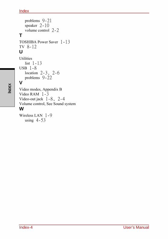
IndexIN
DEX
problems 9-21speaker 2-10volume control 2-2
TTOSHIBA Power Saver 1-13TV 8-12UUtilities
list 1-13USB 1-8
location 2-3, 2-6problems 9-22
VVideo modes, Appendix BVideo RAM 1-3Video-out jack 1-8, 2-4Volume control, See Sound systemWWireless LAN 1-9
using 4-53
Index-4 User’s Manual