
SASKATCHEWAN IRRIGATION DESIGN AND CONSTRUCTION …...Saskatchewan, and follow good engineering...
137
A G R I C U LT U R E IRRIGATION SASKATCHEWAN IRRIGATION DESIGN AND CONSTRUCTION STANDARDS MANUAL PREPARED BY THE SASKATCHEWAN MINISTRY OF AGRICULTURE IRRIGATION BRANCH, ENGINEERING UNIT AUGUST 2012
Transcript of SASKATCHEWAN IRRIGATION DESIGN AND CONSTRUCTION …...Saskatchewan, and follow good engineering...

AGR ICULTUREI R R I G A T I O N
SASKATCHEWAN IRRIGATION DESIGN AND CONSTRUCTION STANDARDS MANUAL
p r e pa r e d by
t h e S a S K at C h e Wa N M I N I S t ry O F a G r I C U Lt U r e
I r r I G at I O N b r a N C h , e N G I N e e r I N G U N I t
aU G U S t 2 0 1 2

Brand Names The manual’s use of brand names is for the convenience of the reader only. The use of brand names does not constitute a recommendation
or an endorsement of these particular products.

AUGUST 2012 2012 Saskatchewan IDC Standards ii
ACKNOWLEDGEMENT In Saskatchewan, particularly in the area around Lake Diefenbaker, initiatives are underway for irrigation infrastructure rehabilitation, irrigation district infill, expansion of existing districts and creation of new districts. Saskatchewan irrigation engineering standards are presented to ensure the irrigation district designs meet the requirements of The Irrigation Act, 1996 and other regulations for Saskatchewan, and follow good engineering practises. The Saskatchewan design standards reference several sources, of note:
1) The Alberta Agriculture and Rural Development, Irrigation Secretariat’s April 2010 manual Irrigation Rehabilitation Program Design and Construction Standards (Alberta IRP Standards) prepared by the Alberta Irrigation Rehabilitation Program (IRP) Standards Review Committee,
2) The Saskatchewan Water Corporation’s April 1988 manual Sprinkler Irrigation Design
Guidelines prepared by irrigation specialists. 3) The Saskatchewan irrigation design criteria used to meet the environmental requirements of
The Irrigation Act, 1996 and used to provide preliminary design services for sprinkler irrigation on individual farms.
The Alberta and Saskatchewan manuals present a compilation of the irrigation design and construction knowledge acquired over the past 40 years. Often the Alberta standards are similar and considered suitable for application in Saskatchewan. There are instances where the Alberta criteria change to reflect the irrigation design practises followed in Saskatchewan. The Saskatchewan Irrigation Design and Construction Standards Manual (Saskatchewan IDC Standards) uses metric units throughout in order to be consistent with Canadian engineering documents. The imperial and United States units are used in the manual in order for the manual to be easily understood by as broad group of irrigators as is possible. The permission given by the Alberta Agriculture and Rural Development to use of the Alberta IRP Standards is appreciated. The insights provided by Len Ring, P. Eng., the past chairman of the Alberta IRP Standards Review Committee, has been invaluable. The information provided by Len Ring, P. Eng., and Jozef Prozniak, P. Eng., at the February 2011 workshop “IRP Design and Construction Standards”, sponsored by the Ministry, clarified topics for the Saskatchewan manual. The participating irrigation district staff and consultants are thanked for their comments – several of which are included in the Saskatchewan standards.
Lloyd Barteski, P. Eng., Engineering Unit, Irrigation Branch, Saskatchewan Ministry of Agriculture August 2012

AUGUST 2012 2012 Saskatchewan IDC Standards iii
FORWARD
The Irrigation Branch of Saskatchewan Agriculture (Ministry) recognizes the need for an irrigation engineering standards manual for Saskatchewan due to:
1) The maturing of the irrigation district infrastructure and the need for asset management planning to replace and upgrade the infrastructure that was built after 1965 around Lake Diefenbaker;
2) The renewal of interest in irrigation through the initiation of government and irrigation district funded programs for rehabilitation of infrastructure, infill and expansion of existing districts, and the potential of new districts in the Lake Diefenbaker area;
3) The transition to independently managed irrigation districts whereby construction initiatives are the district responsibility;
4) The new types of irrigation and water supply management being promoted in irrigation districts;
5) The recognition that irrigation development expertise is being lost as senior staff in both the public and private sectors retire; and
6) The need to document the experiences gained from irrigation in Saskatchewan and Alberta since 1970.
This growth of irrigation has permitted the development of a broadly based and “state of the art” expertise that can be applied as Saskatchewan’s irrigation development moves ahead. The resultant April 26, 2010 publication of Alberta Agriculture and Rural Development, Irrigation Secretariat entitled Irrigation Rehabilitation Program Design and Construction Standards prepared by the Alberta IRP Standards Review Committee, is a model and prime reference for the Saskatchewan IDC Standards. Several of the Saskatchewan manual’s sections refer directly to the Alberta publication. Other sections treat topics differently and these differences become points for discussion and engineering assessment. The Saskatchewan manual relates primarily to centre-pivot irrigation development. Reference is made to gravity and other sprinkler types of irrigation, but the Saskatchewan IDC Standards are for centre-pivot irrigation in particular since this irrigation method will dominate future developments in Saskatchewan. The Saskatchewan Irrigation Design and Construction Standards must be followed for all Ministry provincially funded irrigation engineering projects. The Saskatchewan IDC Standards recognize the maturation of the consulting industry and the design and construction departments of the irrigation districts. As a result, there is less emphasis on provincial government review of irrigation district designs and more responsibility placed on the engineering professionals taking responsibility for the design.
AUGUST 2012 2012 Saskatchewan IDC Standards iv
All IDC projects shall be designed, stamped and signed, by a qualified Professional Engineer (P. Eng.) or Engineering Licensee registered with the Association of Professional Engineers, and Geoscientists of Saskatchewan (APEGS). Where an Engineering Licensee is responsible for the design, the professional’s registration with APEGS must specify that their scope of practise includes the design of irrigation systems. Where the terms “shall”, “must” or “will” are used, it indicates the standards that must be met in all situations where Ministry funds are used. If it is not possible to meet those specified conditions, the proponent shall: Provide an explicit and detailed explanation to the irrigation district and the provincial
funding agency as to why the deviation is necessary, and Provide the explanation early enough in the planning process in order that the funding
agencies can review and comment in writing prior to the making of further commitments. Where the terms “should” or “it is recommended” are used, it indicates the standards that should be met whenever possible. If the responsible professional feels that it is not practical to meet these conditions, and after consulting with the irrigation district and Ministry, they may exercise their personal professional judgement. They remain responsible for the design and shall be prepared to explain the reasons for not meeting the standards in these situations. Where the terms “may” or “can” are used, it indicates components of the standards that are optional. In some cases, it specifies items that exceed the minimum required, but which would result in a better overall long-term project. The responsible professional, in consultation with the irrigation district, is free to exercise their personal professional judgement in these situations. In the Saskatchewan IDC Standards, there are some differences in how the standards address specific issues. They include:
The standards are developed with the expectation that Saskatchewan IDC Standards could be used in conjunction with the Alberta manual in order to provide full documentation for new designers of irrigation water distribution systems.
The Saskatchewan IDC Standards are directed to irrigation district initiatives and to
centre-pivot sprinkler irrigation. Since Saskatchewan infill and expansion funding is limited for gravity and back flood irrigation, references to these types of irrigation have been removed. The water requirements of alternative sprinkler irrigation methods, such as wheel move or big gun sprinkler irrigation, are subject to the design limits and criteria used for centre-pivot irrigation systems.

AUGUST 2012 2012 Saskatchewan IDC Standards v
The determination of the design flow rate is a separate chapter. The calculation of the design flow for smaller blocks of irrigation or projects with a number of small parcels is more detailed. This is necessary since pipelines are often used in these cases and since the consequences are serious if the design flow rate is underestimated. Pipelines do not have any freeboard in which to convey increased flow.
The pipeline chapter includes both material and installation sections. The Saskatchewan IRP Standards may not permit the latitude in the pressure, flow, and material that is permitted by Alberta IRP Standards. A cautionary note to the Saskatchewan IRP specifications is added and a greater responsibility is placed on the designer to ensure the suitability of the pipeline design when making recommendations.
Graphs and curves to be used in the design process continue to be included in the
standards but, where possible, an equivalent equation is included which can be incorporated into a spreadsheet or other computer-aided design processes.
Irrigation in Saskatchewan is subject to The Irrigation Act, 1996. This has implications
for irrigation on individual farms and in irrigation districts. Notably, prior to the allocation of water, it is necessary to obtain irrigation certification from the Ministry’s Irrigation Branch and approvals for the Saskatchewan Watershed Authority (SWA).

AUGUST 2012 2012 Saskatchewan IDC Standards vi
TABLE OF CONTENTS CHAPTER 1: REQUIRED FLOW RATE 1
1.1 FINAL GROSS AND NET DESIGN FLOW RATES 1 1.1.1 Design Flow Rate For Irrigated Areas Supplied by Canals 3 1.1.2 Calculating Design Flow Rates by the Parcel-by-Parcel Method 4 1.1.3 Small Block Design by the Parcel-by-Parcel Method for Canal Systems 9 1.1.4 Small Block Design by the Parcel-by-Parcel Method for Pipeline Systems 9
1.2 GROSS DESIGN FLOW RATE (QG) 12 1.3 CLIMATIC REDUCTION FACTOR (CRF) 13 1.4 FLOW RATES FOR OTHER USERS 14 1.5 NATURAL RUNOFF 14 1.6 SURGE CAPACITY 14 1.7 WASTE WAYS 15 1.8 FINAL TOTAL DESIGN FLOW RATE (QF) 16
CHAPTER 2: CANALS 17 2.1 OPEN CHANNEL DESIGN CRITERIA 17
2.1.1 Manning’s Formula 17 2.1.2 Bank Side Slopes 18 2.1.3 Bed Slope 18 2.1.4 Freeboard 19 2.1.5 Bank Width 20 2.1.6 Bed Width to Water Depth Ratio 20 2.1.7 Flow Velocity 20 2.1.8 Gravel Armour 23 2.1.9 Radius of Curvature 23 2.1.10 Spacing of Check Structures 23
2.2 OTHER CANAL COMPONENTS 24 2.2.1 Berms 24 2.2.2 Cross Drains 24 2.2.3 Surface Drain Inlets 24
2.3 BURIED MEMBRANE LINED CANALS 25 2.3.1 Side Slopes 25 2.3.2 Lining Cover 25 2.3.3 Gravel Armour Over Lined Earth Canals 26 2.3.4 Freeboard 26 2.3.5 Woven Fabric Polyethylene Liners 26 2.3.6 Polyvinylchloride Liners 27 2.3.7 Membrane Lining Installation 27
2.4 CONCRETE LINED CANALS 28 2.5 CANALS WITH EXPOSED LINERS 28 2.6 WASTE WAYS 28
2.6.1 Controlled Waste Ways 28 2.6.2 Uncontrolled Waste Ways 29 2.6.3 Utilities 29
AUGUST 2012 2012 Saskatchewan IDC Standards vii
CHAPTER 3: PIPELINES 30 3.1 PIPE MATERIALS 30
3.1.1 Thermoplastic Pipe 30 3.1.1.1 Polyvinyl Chloride Pipe 30 3.1.1.2 PVC Ribbed Sewer Pipe 31 3.1.1.3 High Density Polyethylene Pipe 31 3.1.1.4 Lightweight Low-Pressure HDPE Pipe 31
3.1.2 Concrete Pipe 32 3.1.2.1 Pre-Stressed Concrete Cylinder Pipe 32 3.1.2.2 Pre-Tensioned Concrete Cylinder Pipe 32 3.1.2.3 Non-Cylinder Reinforced Concrete Pressure Pipe 32 3.1.2.4 Reinforced Concrete Low Head Pressure Pipe 33
3.1.3 Corrugated Steel Pipe 33 3.1.3.1 Standard Corrugated Steel Pipe 33 3.1.3.2 Corrugated Steel Storm Sewer Pipe 33
3.2 PIPELINE DESIGN 34 3.2.1 Hydraulic Grade Lines 34 3.2.2 Hydraulic Formulae 34
3.2.2.1 Closed Pipelines 34 3.2.2.2 Open Pipelines 35
3.2.3 Roughness Coefficients 35 3.2.4 Entrance Losses 36 3.2.5 Operating Pressures 36 3.2.6 Velocity Limits 42
3.2.6.1 Closed Pipelines 42 3.2.6.2 Open Pipelines 43
3.2.7 Maximum Slope 43 3.2.8 Surge Protection 43 3.2.9 Surge Calculations 43 3.2.10 Corrosion Prevention 44 3.2.11 Turnout Sizing 44 3.2.12 Thrust-Blocks, Restraints and Anchors 45 3.2.13 Pipeline Drains 47 3.2.14 Culverts 47
3.3 INLETS, FITTINGS, TURNOUTS AND OUTLETS 48 3.3.1 Settling Ponds 48 3.3.2 Trash Racks 49 3.3.3 Inline Fittings and Valves 49 3.3.4 Turnouts 49 3.3.5 Air Valves 50 3.3.6 Energy Dissipaters 51
3.4 PIPELINE INSTALLATION 51 3.4.1 General Requirements: PVC and HDPE Pipe 51
3.4.1.1 Trench Width 52 3.4.1.2 Trench Bottom and Bedding 53 3.4.1.3 Pipe Assembly 53 3.4.1.4 Deflection and Bending 53 3.4.1.5 Pipe Haunches and Backfill 54 3.4.1.6 Minimum Earth Cover 54 3.4.1.7 Tracer Wire or Tape 54 3.4.1.8 Pressure and Leak Testing 55
3.4.2 Alternative Procedures: Smaller, High Pressure PVC Pipe 56 3.4.2.1 Trench Construction 56
3.4.3 Special Considerations: HDPE Pipe 56 3.4.4 Special Considerations: Corrugated Steel Storm Sewer Pipe 57
AUGUST 2012 2012 Saskatchewan IDC Standards viii
3.4.5 Special Considerations: Rigid Concrete Pipe 57 3.4.5.1 Trench and Bedding 58 3.4.5.2 Pipe Assembly 58 3.4.5.3 Backfill, Pipe Haunches and Compaction 58
3.4.6 Special Considerations: Semi-Rigid Concrete Pipe 59 3.4.7 Utilities 59
CHAPTER 4: CONSTRUCTION AND HYDRAULIC STRUCTURES 60 4.1 CAST-IN-PLACE CONCRETE STRUCTURES 60 4.2 STANDARD FEATURES: CAST-IN-PLACE CONCRETE STRUCTURES 61
4.2.1 Concrete Properties 61 4.2.2 Reinforcing Steel 61 4.2.3 Structural Freeboard 61 4.2.4 Cut-Off and Curtain Walls 61 4.2.5 Stoplogs and Flashboards 62 4.2.6 Safety 62 4.2.7 Sub-Slab Drainage 62 4.2.8 Concrete Cover 62 4.2.9 Soft Soil Subgrade 63 4.2.10 Sub-Slab Insulation 63 4.2.11 Foundation Concrete (Mud Slab) 63 4.2.12 Minimum Thickness of Slabs and Walls 63 4.2.13 Expansion Joints 63 4.2.14 Steel Components and Corrosion Protection 64 4.2.15 Soil Loads and Hydrostatic Pressure 64 4.2.16 Seepage Path 66 4.2.17 Standard Riprap Sizes 66 4.2.18 Standard Filter Gravel and Bedding Gravel Gradations 67
4.3 CAST-IN-PLACE INLINE STRUCTURES 68 4.3.1 Structural Freeboard 68 4.3.2 Check Structures 68 4.3.3 Vertical Check-Drop Structures 74 4.3.4 Chute Check-Drop Structures 80 4.3.5 Vertical Drop Structures 85 4.3.6 Chute Drop Structures 90
4.4 TURNOUTS AND WASTE WAYS 95 4.4.1 Gated Turnouts 95
4.4.1.1 Large Lateral Turnouts and Head Gates 95 4.4.1.2 Pipe Turnouts 95 4.4.1.3 Gated Chute Turnouts 96
4.4.2 Pipeline Inlet Structures 96 4.4.3 Wet-Well Pump Turnouts 96
4.4.3.1 High Side Turnouts 97 4.4.3.2 Low Side Turnouts 97
4.4.4 Major Waste Ways 97 4.5 PRECAST CONCRETE STRUCTURES 97
CHAPTER 5: SEEPAGE CONTROL 98 5.1 CUT-OFF CURTAINS 99
5.1.1 Cut-off Curtains – Inside Canals 99 5.1.2 Cut-off Curtains – Outside Canals 99
5.2 CLAY CUT-OFF (CORE TRENCH) CURTAIN 100

AUGUST 2012 2012 Saskatchewan IDC Standards ix
5.3 INTERCEPTOR DRAINS 100 5.3.1 Open Interceptor Drains (Ditches) 100 5.3.2 Pipe Interceptor Drains 100
5.3.2.1 Drain Depth 100 5.3.2.2 Drain Gradient 101 5.3.2.3 Manholes 101 5.3.2.4 Outlets 101
5.4 GRID SUB-SURFACE DRAINAGE 101 5.4.1 Grid Sub-Surface Drainage Design 102
5.4.1.1 Drain Depth 102 5.4.1.2 Drain Gradient 102 5.4.1.3 Outlets 102 5.4.1.4 Manholes and Air Inlets 102
5.4.2 Grid Drain Construction 103 5.4.2.1 Trenching 103
5.5 DRAINAGE MATERIALS 103 5.5.1 Corrugated PE Drain Pipe 103 5.5.2 Perforated PVC Pipe 103 5.5.3 Gravel Chimney 104 5.5.4 Gravel Bedding 104 5.5.5 Filter Socks 104 5.5.6 Manholes 105
CHAPTER 6: SURFACE DRAINAGE WORKS 106 6.1 REQUIRED CAPACITIES 106 6.2 OPEN CHANNEL DRAINAGE DESIGN 106 6.3 CULVERT CROSSINGS 107 6.4 OUTLETS AND DISCHARGE 107
APPENDIX A: DEFINITIONS 108 APPENDIX B: ABBREVIATIONS AND ACRONYMS 114 APPENDIX C: DERIVATION OF IRRIGATION NET FLOW RATES 115 APPENDIX D: THRUST-BLOCKING, RESTRAINTS AND ANCHORS 118 APPENDIX E: CONVERSION FACTORS 120 APPENDIX F: STANDARDS AND REFERENCES 121

AUGUST 2012 2012 Saskatchewan IDC Standards x

AUGUST 2012 2012 Saskatchewan IDC Standards 1
CHAPTER 1: REQUIRED FLOW RATE The flow rates needed for canal and pipeline water supply systems depend upon the type of irrigation, the irrigated area, the number and size of irrigated parcels, and the physical geographic characteristics of the location. Information presented in the Alberta April 2010 manual Irrigation Rehabilitation Program Design and Construction Standards, the Saskatchewan Water Corporation’s Sprinkler Irrigation Design Guidelines, and design practises followed by the Ministry’s Irrigation Branch, notably for the preliminary design of individual sprinkler irrigation projects, are the basis for this chapter. The Saskatchewan standards apply directly to irrigation district development with centre-pivot sprinkler irrigation.
1.1 FINAL, GROSS AND NET DESIGN FLOW RATES The flow rates recommended for irrigation projects need to take into account many possible inflows and outflows. The final design flow rate (QF) for a water supply system shall be equal to the gross flow rate (QG) required for irrigation, adjusted for climate and for non-irrigation water uses. QF is further discussed in Section 1.8. The gross design flow rate (QG) is the amount of water supplied for irrigation at the start of the water distribution system. QG is modified by the downstream efficiencies of the water conveyance system between the start of the irrigation water supply and the point of delivery to individual farm turnouts inside the irrigated area, sometimes described as an irrigation block. The water conveyance system can be canals, pipelines or a combination of the two. QG is more fully described in Table 1.1 and Section 1.2.

AUGUST 2012 2012 Saskatchewan IDC Standards 2
Table 1.1: Summary Table For Required Flow Rates Criteria Canal Systems Pipeline Systems
Large Blocks For more than 2,000 ha (5,000 ac) or more than 60 parcels
Shall use: Area-Method Figures & formula1.1a to 1.1d Section 1.1.1, Table C-1
Shall use: Parcel-by-Parcel Method Section 1.1.2
Large Blocks For more than 2,000 ha (5,000
ac) or more than 60 parcels but when more than 10% of
the block area is gravity irrigated
Shall use: Parcel-by-Parcel Method
Section 1.1.2
Shall use: Parcel-by-Parcel Method
Section 1.1.2
Medium Blocks For 810 ha (2,000 ac) to 2,000 ha (5,000 ac) where more than 80% of parcels are larger than 32 ha (80 ac) and more than
90% of block area is sprinkler irrigated
Should use: Area-Method Figures & formula1.1a to 1.1d Section 1.1.1, Table C-1
Shall use: Parcel-by-Parcel Method Section 1.1.2
Medium Blocks For 810 ha (2,000 ac) to 2,000 ha (5,000 ac) where less than 80% of parcels are more than 32 ha (80 ac) or where less than 90% of block area is
gravity irrigated
Shall use: Parcel-by-Parcel Method Section 1.1.2
Shall use: Parcel-by-Parcel Method Section 1.1.2
Small Blocks For less than 810 ha (2,000 ac) or less than 30 parcels
Should use: Parcel-by-Parcel Method Section 1.1.2
Shall use: Parcel-by-Parcel Method Section 1.1.2
The designer is responsible to review the appropriate sections in the Saskatchewan IDC
Standards manual before making recommendations.
The net design flow rate (QN) is the total of the amount of water delivered to farm turnouts inside an irrigated area. QN equals QG less any conveyance losses. It should be noted that the different types of irrigation used on the individual farms have different application efficiencies. So QN will differ from the amount of water being applied to the irrigated crops. These application losses are discussed in the manual Sprinkler Irrigation Design Guidelines.

AUGUST 2012 2012 Saskatchewan IDC Standards 3
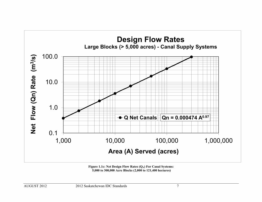
1.1.1 Design Flow Rate For Irrigated Areas Supplied by Canals When canals supply individual farms that use centre-pivot sprinkler irrigation then the area- method applies, as shown in Figures 1.1a to 1.1d and the corresponding equations. Figures 1.1a to 1.1d: 1) shall be used to calculate the net design flow rate (QN) for canal systems serving large
irrigated area blocks (more than 2,020 hectares (5,000 acres), or more than 60 parcels). Note: where less than 90 per cent of the block area is irrigated by sprinkler methods (namely, more than 10 per cent of area is gravity irrigation) then the parcel-by-parcel method must be used rather than the figures and equations. If the figures and equations are used in this latter case, the design flow rate will be under-estimated;
2) should be used to calculate the QN for canal systems serving blocks from 810 to 2,000 hectares (2,000 to 5,000 acres) in size when the project is made up primarily of full quarter section parcels using centre-pivot sprinkler irrigation; and
3) can be used to calculate the QN for canals supply systems serving blocks from 810 to 2,000 hectares (2,000 to 5,000 acres) blocks, where more than 80 per cent of the parcels are larger than 32 hectares (80 acres) and where more than 90 per cent of the block area is irrigated by sprinkler methods (namely, less than 10 per cent of area is gravity irrigation).
Figure 1.1a to 1.1d are approximately straight lines on log-log paper, so QN can also be calculated using the equations:
QN = 0.00117 (H 0.97)
where QN = net design flow rate (m3/s) required to serve the irrigated area, H = the irrigated area (hectares)
Figures 1.1c and 1.1d: QN using Metric units and A (area) using Imperial units:
QN = 0. 000474 (A 0.97 )
where QN = net design flow rate (m3/s) required to serve the irrigated area, A = the irrigated area (acres)
The QN values determined by the area-method are estimated for a water conveyance efficiency (Ec) of 100 per cent. However, conveyance losses (seepage, evaporation, or operational discharge flow) need to be included in the design to calculate the gross design flow rate (QG).

AUGUST 2012 2012 Saskatchewan IDC Standards 4
For unlined canals, the recommended Ec is 85 per cent (see Section 1.2), therefore QG is calculated:
QG = QN / 0.85 or
QG = 0.00138 H 0.97 where QG = net design flow rate (m3/s) required to serve the irrigated area,
H = the irrigated area (hectares)
Calculations for QG using Metric units and A (area) using Imperial units are:
QG = QN / 0.85 or
QG = 0.000558 A 0.97
where QG = net design flow rate (m3/s) required to serve the irrigated area, A = the irrigated area (acres)
In order to determine the final design flow rate (QF) for the project, QG needs to account for climate as described in Section 1.3 and for non-irrigation flows as described in Section 1.4.
1.1.2 Calculating Design Flow Rates By The Parcel-by-Parcel Method The parcel-by-parcel method focuses on the anticipated area irrigated on each parcel of land in a block of irrigation development. A parcel is the area of land irrigated by one irrigation system. The area estimated for each parcel should be the total area that can reasonably be expected to be served in that parcel in the future. The Parcel-by-Parcel method determines the net design flow rate (QN) by totalling the flows required for each individual parcel to determine maximum flow rate (QM). Then QM is reduced when all the parcels are not being irrigated at the same time during the peak demand period. The lower flow rate is determined by considering the total number of parcels in the irrigated block.

AUGUST 2012 2012 Saskatchewan IDC Standards 5
Figure 1.1a: Net Design Flow Rates (QN) For Canal Systems (Metric Units): 2,000 to 121,400 Hectare Blocks (5,000 to 300,000 acres)
Qn = 0.00117H0.97
0.1
1.0
10.0
100.0
100 1,000 10,000 100,000Net
Flo
w (Q
n) R
ate
(m3 /s
)
Area (H) Served (hectares)
Design Flow Rates (Metric Units) Large Blocks (>2,000 hectares) - Canal Supply Systems
Q Net…

AUGUST 2012 2012 Saskatchewan IDC Standards 6
Figure 1.1b: Net Design Flow Rates (QN) For Canal and Pipeline Supply Systems (Metric Units): 810 to 12,100 Hectare Blocks (2,000 to 30,000 acres)
Qn = 0.00117H0.97
0.1
1.0
10.0
100 1,000 10,000 100,000Net
Flo
w (Q
n) R
ate
(m3 /s
)
Area (H) Served (hectares)
Design Flow Rates (Metric Units) Small Blocks (810 to 12,100 hectares) - Canal Supply Systems
Q Net Canals
AUGUST 2012 2012 Saskatchewan IDC Standards 7
Figure 1.1c: Net Design Flow Rates (QN) For Canal Systems:
5,000 to 300,000 Acre Blocks (2,000 to 121,400 hectares)
Qn = 0.000474 A0.97
0.1
1.0
10.0
100.0
1,000 10,000 100,000 1,000,000
Net
Flo
w (Q
n) R
ate
(m3 /s
)
Area (A) Served (acres)
Design Flow Rates Large Blocks (> 5,000 acres) - Canal Supply Systems
Q Net Canals

AUGUST 2012 2012 Saskatchewan IDC Standards 8
Figure 1.1d: Net Design Flow Rates (QN) For Canal & Pipeline Supply Systems: 2,000 to 30,000 Acre Blocks (810 to 12,100 hectares)
Qn = 0.000474 A0.97
0.1
1.0
10.0
1,000 10,000 100,000Net
Flo
w (Q
n) R
ate
(m3 /s
)
Area (A) Served (acres)
Design Flow Rates Small Blocks (2,000 to 30,000 acres) - Canal Supply Systems
Q Net Canals

AUGUST 2012 2012 Saskatchewan IDC Standards 9
1.1.3 Small Block Design By The Parcel-by-Parcel Method For Canal Systems The parcel-by-parcel method is recommended for both canal and pipeline systems. The parcel-by-parcel method:
1) shall be used to calculate QN for canals systems serving blocks less than 810 hectares (2,000 acres) or less than 30 parcels, and
2) shall be used to calculate QN for canals systems serving blocks between 810 to 2,000 hectares (2,000 to 5,000 acres), when there is a significant number of small parcels (more than 20 per cent of the parcels are less than 32 hectares (80 acres) or if there is a significant amount of gravity irrigation (more than 10 per cent of the area).
1.1.4 Small Block Design By The Parcel-by-Parcel Method For Pipeline Systems The parcel-by-parcel method shall be used to determine QM and QN for all open and closed pipeline water supply systems, regardless of the size of the area served. For information purposes, Table 1.2 estimates the area, flow rate (QP) and supply pipeline diameter suitable to supply a single centre-pivot irrigated parcel. The maximum flow rate (QM) required is the sum of the flows (QP) for all of the parcels, i.e.:
QM = ∑ QP The number of parcels is not necessarily the same as the number of turnouts, since a single turnout may serve more than one parcel. However, in the future this could change, so in some cases the water supply design should provide for the future irrigation development.

AUGUST 2012 2012 Saskatchewan IDC Standards 10
Table 1.2: Estimated Flow Rates per Parcel (QP) Size of Irrigated Parcel
(Current & Potential)
Flow Required
(Centre-Pivot Sprinkler Irrigation)
PVC Pipeline Diameter
(IPS)
(Hectares) (Acres) (m3 /s) (ft.3/s) (US gpm) (US gpm /acre) (mm) (Inches)
< 12 < 31 0.0139 0.490 220 7.0 100 4”
12 to 27 31 to 68 0.0303 1.07 480 7.0 150 6”
27 to 46 68 to 114 0.0505 1.78 800 7.0 200 8”
46 to 52 114 to 130 0.0574 2.03 910 7.0 250 10”
52 to 72 130 to 180 0.0780 2.80 1,260 7.0 250 10”
>72 > 180 (To be determined on a case by case basis.)
Note: Bold values are the base values. Other values are unit equivalents.
Note: Pipeline Diameters are for SDR 41 PVC (IPS) pipe sized so the flow velocity is less
than 1.52 m/s (5.0 ft./s)
The calculation of QM requires all parcels to be irrigated at the same time. The net design flow rate (QN) is less than QM when all the parcels are not irrigated at the same time. That is often the case, depending on the number of parcels in the irrigated block. The calculation of QN requires the QM to be multiplied by a Utilization Reduction Factor (URF), namely:
QN = QM (URF) The URF factor can be determined from Table 1.3 or by a calculation method as shown in the examples below.
Table 1.3: Non-Irrigated Areas For Parcel-by-Parcel Method Total Number of Parcels Served Number of Parcels NOT Being Irrigated At The Same Time
1 to 7 0 8 to 11 1 12 to 16 2 17 to 21 3 22 to 26 4 27 to 31 5 32 to 36 6 37 to 41 7 42 to 46 8 47 to 51 9 52 to 56 10 57 to 60 11
60+ (To be determined on a case-by-case basis)

AUGUST 2012 2012 Saskatchewan IDC Standards 11
Example 1:
When there are seven (7) parcels or fewer, then in conformity with Table 1.3, the Utilization Reduction Factor (URF) is 1.0. Therefore, QN equals QM since during the peak demand period, all parcels are being irrigated at the same time. Therefore when there are 7 parcels or less, then
QM = ∑ QP Example 2: When there are eight (8) parcels or more, it is likely that during the peak demand period, not all parcels are irrigated at once and QN shall be calculated by one of two methods:
1) Through the utilization of the URF to determine QM, and QN, calculated as follows:
Firstly calculate: URF = 0.8 + (0.8/N)
where N = the number of parcels being served (for example eight (8) parcels).
Secondly calculate: QM = ∑ QP
Thirdly calculate: QN = QM (URF) For example:
Determine QN where there are eight equal sized parcels of 46.1 ha (114 acres). So:
URF = 0.8 + (0.8/8) = 0.9
From Table 1.2: Qp = 0.0505 m3 /s (800 US gpm) per parcel
QM = 0.0505 (8) = 0.404 m3 /s (6,400 US gpm)
Then
QN = (8 * 0.0505) * 0.9 = (0.404) * 0.9 = 0.364 m3 /s (5,760 US gpm)
2) Through direct calculation of QN by reducing the number of parcel(s) not being irrigated at any one time as shown in Table 1.3. The selected parcels should maximize the irrigated area. QN should equal the sum of the largest combination of individual flows (QP) for the remaining parcels that are being irrigated, namely:
QN = ∑ QP
For example:
Determine QN where there are eight equal sized parcels of 46.1 ha (114 acres). So: From Table 1.3: number of parcels not irrigated = 1
From Table 1.2: QN = (8 – 1) * 0.0505 = (7) * 0.0505 = 0.354 m3 /s (5,600 US gpm)

AUGUST 2012 2012 Saskatchewan IDC Standards 12
The designer is responsible for selecting the most suitable flow rate and the rational shall be presented at the planning stage of the irrigation project development process.
Example 3: When there are more than 60 parcels, then 20 per cent of the parcels are estimated not to be irrigated at any one time. The designer is responsible to determine the parcels that are not irrigated. Similar to Example 2, QN equals the sum of the individual flows (QP) for the remaining irrigated parcels:
QN = ∑ QP Example 4: When there is an existing half-mile-long centre-pivot system on a full section of land, the required flow rate for that turnout should be calculated based on four individual quarter-section parcels, even though that is not what currently exists. Within blocks divided into conventional quarter sections, the parcel size is recommended to be 52.6 hectares (130 acres). In other areas where future irrigation could include systems irrigating more than 52.6 hectares (130 acres), such as corner-arm development, or where surveyed quarter sections are not a constraint (e.g. grazing reserves, new large-scale developments), then the QP for each parcel should be determined on an individual basis.
1.2 GROSS DESIGN FLOW RATE (QG) As calculated in Section 1.1 for large or small blocks, QN is an estimate of the net flow rate delivered to farm turnouts in the irrigation block. However, conveyance losses (seepage from unlined canals, evaporation, and operational discharges) need to be included in the design in order to determine the total quantity of irrigation water needed to supply the irrigation block. QG equals QN plus any conveyance losses and is the total irrigation flow diverted into the conveyance system. The water conveyance efficiency (Ec) is defined as the quantity of water delivered to the farm turnouts (QN) divided by the quantity of water diverted into the water supply system (QG) or:
Ec = QN / QG

AUGUST 2012 2012 Saskatchewan IDC Standards 13
Design values for Ec are shown in Table 1.4:
Table 1.4: Water Conveyance Efficiencies (Ec) Type of Distribution System Ec (%) Ec
Closed Pipeline 100 1.00 Open Pipeline 90 0.90
Lined Canals (evaporation and operational discharge only) 90 0.90 Canal System (evaporation, seepage, operational discharge flow) 85 0.85
Providing tail water capacity (return flow) for gravity irrigation systems is not required for the centre-pivot irrigation described in the Saskatchewan standards. However, the operational discharge flow from canal systems needs to be included in the calculations. The operational discharge flow in open canal systems is the minimum amount of water the canal system needs to convey in order to supply all irrigation turnouts in a timely manner. In some instances, the operational discharge flow can be reduced when canal system is confined, specifically when the canal flow and static head can be contained within the height of the canal embankments and control gates. The gross design flow rate (QG) shall be calculated as follows:
QG = QN /Ec
To determine the final design flow rate (QF) for the project, QG should be modified as outlined in Section 1.3 and Section 1.4.
1.3 CLIMATIC REDUCTION FACTOR (CRF) In Saskatchewan, typically the Climate Reduction Factor (CRF) is 1.0 and the nominal irrigation water supply is 0.0655 m3/min per hectare (7.0 US gpm per acre). However, in some locations where the climate has more precipitation, such as in north-central and north-eastern Saskatchewan, the CRF may be less. The CRF is Table 1.5:
Table 1.5: Climatic Design Flow Rate Adjustment
Irrigation Districts Climatic Reduction Factor (CRF) Nominal Water Supply
m3/min per hectare (US gpm per acre)
South of Saskatoon 1.0 0.0655 (7.0)
North of Saskatoon 0.8 to 1.0 0.0524 to 0.0655 (5.6 to 7.0)

AUGUST 2012 2012 Saskatchewan IDC Standards 14
This lower CRP rate is explicitly shown on the Ministry’s irrigation certification for the proposed irrigation area, otherwise the typical water supply rate shall be used in calculations.
1.4 FLOW RATES FOR OTHER USERS In cases where there are significant other non-irrigation uses within the area of the irrigation block and where water is required at the same time as the peak irrigation demand, then the gross design flow rate (QG) must increase. The non-irrigation flow rate (QNI) required by those other uses must be added to the QG calculated for irrigation needs. If the other water uses do not occur at peak times, then the QG does not need to be increased. The flow required for these other uses should be estimated by the designer on a case-by-case basis.
1.5 NATURAL RUNOFF In addition to the flow rate required for irrigation and other demands, calculations must ensure canals and drains are capable of conveying flows created by runoff from snowmelt, storm water, or surface drainage. The local runoff flow rate from the contributing drainage areas or basins are recommended to be determined by the peak potential hydrology studies completed by the Saskatchewan Watershed Authority. Peak flow rates that could occur from spring snowmelt and summer rainstorms should be included in the design of drainage control structures. See Section 2.2.3 for more information on runoff and surface drain inlets.
1.6 SURGE CAPACITY Surge capacity must be included in the design of canals. The design flow rate at the downstream end of the canal system must be sufficient to carry all possible flows. That includes normal operational spill water as well as:
Any possible surge flows caused by natural runoff from summer storms or snowmelt, and Increased canal flows due to upstream shut-downs due to the closure of pipelines, to
electrical power outages of pumping units, or to operational stoppages of farm irrigation systems.
In recent years, the conversion of gravity irrigation to centre-pivot sprinkler irrigation and of open canals to closed pipeline distribution systems has resulted in an increased need to design for surge flows. Flow that was considered to be discharged as gravity irrigation return flow or as overflow in field supply canals now remains in the main canal. This water moves downstream in the main canal and needs to be discharged by emergency waste ways and terminal waste ways (Section 1.7).

AUGUST 2012 2012 Saskatchewan IDC Standards 15
The portion of the open canal downstream of the last emergency waste way must still be sized to handle the remaining expected flow until it is finally discharged through adequately sized terminal waste ways. Alternatively, there may be opportunities to hold the extra surge flow water volumes in emergency settling ponds or basins excavated near the downstream end of canals. When adding automation to control gates, the automated controls must provide for emergency situations and unexpected surcharges, such as those caused by power outages. The automated gates may need to be programmed to not lower to less than a pre-determined setting. Fail safe design should be programmed into the controls for the automated structures. In some cases, lateral closed pipelines can be equipped with drain pipelines or discharge outlets. These drains can be operated manually or with automatic or remote controls to provide emergency release of water. Where possible, the upstream portion of the canal system should be used as a partial retention pond.
1.7 WASTE WAYS Where waste ways are included in a canal system, they are classified as emergency or terminal waste ways. An emergency waste way differs from terminal waste ways in its sizing and location. An emergency waste way is located on the side of the canal, near the middle of the canal system, or at a point upstream of any open canal to pipeline transition. They normally outlet into a surface drainage channel and are not normally required unless the length of canal exceeds 10 km (6 miles) or the canal to pipeline transition results in the elimination of the ability to handle surge flows. The design flow rate of an emergency waste way depends on the particular situation and should equal at least 15 per cent of the canal flow rate at its source, or the estimated surge flow that could result from upstream pipelines or sprinkler systems shutting down unexpectedly. In some cases, unexpected flow increases may be handled by upstream (manual or automatic) emergency waste ways.
A terminal waste way is a spillway or an overflow channel that drains from a canal into a water body or surface drainage channel. These are required at the lower end of supply canals having an initial flow rate in excess of 0.7 m3/s (24 ft.3/s). They are also advisable on all canals serving a majority of sprinkler irrigation parcels or canals with significant closed pipeline inlets. The flow rate for a terminal waste way equals the greater of the canal flow rate upstream of the waste way or, for initial estimating purposes, 15 per cent of the initial flow rate in the canal. If there are a significant number of closed pipelines upstream, the waste way’s flow rate should increase and should take into account the effect of any upstream emergency discharge.
Waste ways should be located where there are feasible drain outlets or drainage channels. Erosion and flood protect measures must be constructed to prevent erosion or flooding damage to the drainage channel downstream of the waste way outlet. Section 2.6 contains additional

AUGUST 2012 2012 Saskatchewan IDC Standards 16
information on waste ways. Additional information on the design of waste ways can be found in Section III, pages III-7 to III-9 of the manual Channel Systems Design for Southern Alberta.
1.8 FINAL TOTAL DESIGN FLOW RATE (QF) The final design flow rate (QF) for the pipeline or canal systems shall be equal to the gross flow rate required for irrigation (QG), adjusted for climatic reduction factors (CRF) and for non-irrigation uses (QNI) that require water during the peak irrigation demand period, as follows:
QF = (QG) (CRF) + ∑ QNI
This QF value shall be compared to the maximum estimated flow rates required for runoff into the canal (Section 1.5) or surge flows (Section 1.6) in order to confirm the final design flow rate (QF) for the water supply system. Canals shall be capable of handling the final design flow rate (QF) expected during normal operation within the design FSL. Short term or unpredictable high flows (for example, summer storm water) or surge flows may be conveyed within the freeboard of the canal.

AUGUST 2012 2012 Saskatchewan IDC Standards 17
CHAPTER 2: CANALS
Canals are open channels designed to convey irrigation water either to serve smaller canals or laterals or to deliver irrigation water to farm turnouts or sub-laterals. Canals shall be planned and excavated to cross sections and gradients designed from recognized engineering standards. Canals may be bare earth, membrane lined, clay lined, gravel armoured or concrete lined. Earth canals usually have a trapezoidal cross section. Where needed, designs should include compaction of the banks or fill and armouring of side slopes in order to increase the stabilization and water-tightness of canals.
2.1 OPEN CHANNEL DESIGN CRITERIA In the design of canals for irrigation systems in Saskatchewan, the most common design is for a trapezoidal open channel constructed of earth with or without armouring and/or lining. A number of criteria must be met during the process of that canal design.
2.1.1 Manning’s Formula Hydraulic calculations for open channels (canals) shall use the Manning’s formula:
Q = (A/n)R2/3S1/2 where Q = flow rate (m3/s) n = Manning’s roughness coefficient A = cross sectional area of flow (m2) R = hydraulic radius (m), (cross sectional area of flow / wetted perimeter) S = channel bed slope (m/m)
Manning Formula calculations for Q (flow rate) using Imperial units are:
Q = (A)(1.486/n)R2/3S1/2 where Q = flow rate (ft.3/s) n = Manning’s roughness coefficient A = cross sectional area of flow (ft.2) R = hydraulic radius (ft.), (cross sectional area of flow / wetted perimeter) S = channel bed slope (ft./ ft.)

AUGUST 2012 2012 Saskatchewan IDC Standards 18
The values shown in Table 2.1 should be used for Manning’s roughness coefficient for both earth channels and gravel armoured channels.
Table 2.1: Manning’s Roughness Coefficients (n)
Capacity Range (m3/s) Manning’s Coefficients (n)
0 to 3 0.040 3 to 20 0.035
20 to 30 0.030 30 to 75 0.028
Greater than 75 0.025
These values are for a completed canal, after normal vegetative cover has established itself. A newly constructed canal may have a significantly lower roughness coefficient. The values used for Manning’s roughness may be modified by the designer in some situations. Flow depth calculations should use lower roughness coefficient (e.g. 0.025) in order to ensure that the water depth is adequate to provide a sufficient water level at all delivery or turnout points in the years immediately after construction. If this is an issue, additional check structures may be required.
2.1.2 Bank Side Slopes The horizontal-to-vertical ratio (H:V) for inside bank side slopes should be 2½:1 (2½ horizontal to 1 vertical) except where the soil type, or the presence of a liner, requires flatter slopes in order to provide a stable cross section. Where the depth of cut is large, the side slopes and location of driving banks may require special design considerations. The outside bank side slopes should be 2:1 or flatter. In special cases where slope stability is required or where machinery drives on the bank (e.g. for maintenance, mowing) then flatter side slopes (4:1 or flatter) should be designed. A common practise is to design for a 2:1 compacted outside bank slope, but allow the placement of waste material on the outside bank resulting in a final slope flatter than 2:1.
2.1.3 Bed Slope Bed slope (S) is selected within the relationship between soil characteristics and the limits of permissible water velocity. The canal bed slope shall not be so steep that resultant water velocity erodes the canal, or so flat that the water velocity allows the canal to fill with silt (refer to Figure 2.1).

AUGUST 2012 2012 Saskatchewan IDC Standards 19
The steepest allowable slope for earth channels should be 0.001, and usually this slope is restricted to small canals or drains. The preceding criteria should be followed whenever possible. However, where an existing canal is to be rehabilitated at its present location, the bed slope of the existing canal may dictate the bed slope(s) possible for the new canal.
2.1.4 Freeboard Freeboard is the vertical distance from the full supply level (FSL) or water level checked depth, to the top of the canal bank of a canal, irrespective of whether or not armour is present on the entire bank. Freeboard is necessary to protect against the high water levels of surge flows (the sudden increased flows and water levels due to upstream system shutdowns) or of significant and unpredicted precipitation events (e.g. severe summer storms or unusually high spring runoff). When water delivery systems are converted from open channels to pipelines and when irrigators use electricity powered pumps, the issue of upstream system shutdowns becomes more serious. Therefore, freeboard may need to be further increased, depending on the risk of failure and the potential for damage downstream in order to accommodate the surge flows. In no case shall the design freeboard (Fb) be less than 600 mm (24”) and should be calculated as:
Fb = (0.375 d) + 0.2 where d = design flow depth in metres, and Fb = the design freeboard in metres
Local inflows from natural runoff also needs to be handled within the freeboard. As a guideline, it is recommended that at least 300 mm (12”) of freeboard remains in the event of the one-in-100 year (1:100) mean daily peak inflow from a summer rainfall event occurring while the canal is flowing at design capacity. Flow estimates should be equivalent to hydrology evaluations provided by the Saskatchewan Watershed Authority. In cases where a canal failure could result in excessive damage, significant economic losses or the loss of life, a larger freeboard or the construction of emergency spillways to spill the excess flows safely may be required. See Sections 1.5 and 1.6 for more detail on natural runoff and surge capacities. The impact of wind and wave action needs to be accommodated within the embankment freeboard. The effects severe wave action should be considered, even though these waves occur infrequently from sustained, high-velocity winds from a critical direction. The risk of wave action coinciding with the inflow from the maximum summer storm runoff also needs to be considered. Factors such as the wind velocity, the duration of the wind, the distance along which

AUGUST 2012 2012 Saskatchewan IDC Standards 20
the wind can act on a body of water (fetch distance), depth of water, width of the canal, and the orientation of the canal, particularly with respect to the direction of prevailing winds are important. The designer should account for this assessment during the planning stages of the project.
2.1.5 Bank Width The minimum bank width should be 4.0 metres (12’). This applies to both the driving bank and the opposite bank. Where this width cannot practically be achieved due to right-of-way considerations, then a narrower bank may be constructed.
A wider driving bank may be constructed due to geotechnical considerations, or in order to accommodate larger maintenance equipment. Driving bank widths of 5.0 to 6.0 metres (16’ to 20’) are common for larger canals.
2.1.6 Bed Width to Water Depth Ratio The design bed width to normal water depth (b/d) ratio should be within the limits shown in Figure 2.2 for reasons of velocity control, water depth fluctuations, practical construction and slope stability. The b/d ratio may be modified, if justified economically, due to increased siltation or maintenance (weed control) concerns.
2.1.7 Flow Velocity The canal design flow velocity should be between the non-silting and non-scouring velocity range for the particular soil type present in the area, and whenever possible, within the desirable range shown in Figure 2.1. The allowable minimum non-silting velocities and maximum allowable non-erosive velocities for flow in canals are also shown in Figure 2.1. The velocity should be checked using a Manning’s roughness coefficient of 0.025 (for the non-silting and non-eroding range). If the velocity is too great, it may be necessary to adjust the canal bed slope.

AUGUST 2012 2012 Saskatchewan IDC Standards 21
Figure 2.1: Minimum Non-Silting and Maximum Non-Erosive Velocities For Canals

AUGUST 2012 2012 Saskatchewan IDC Standards 22
Figure 2.2: Design Bed Width to Bed Depth (b/d) Ratios

AUGUST 2012 2012 Saskatchewan IDC Standards 23
2.1.8 Gravel Armour Gravel armour should be placed on side slopes for all canals larger than 1.5 m3/s (53 ft.3/s). Gravel armour shall also be considered for smaller canals wherever erosion may be a problem. The gravel armour shall be clean stones devoid of contaminating substances such as coal, shale or loam. The gravel gradations and minimum thicknesses should be as shown in Table 2.2.
Table 2.2: Gravel Armour Specifications Design Flow
(m3/s)
Minimum Gravel Armour Thickness
(mm)
Sieve Size
(mm)
Per Cent Passing
(%)
< 30 150
150 100 100 60 – 80 30 20 – 45 10 <15 5 <5
30 or greater 200
200 100 100 60 – 80 30 20 – 45 10 <15 5 <5
Where gravel armour is used on canals, it shall extend at least 300 mm (12”) vertically above the canal design FSL.
2.1.9 Radius of Curvature The minimum radius of curvature of the centre-line of the canal should be four (4) times the water surface width at design FSL.
2.1.10 Spacing of Check Structures The depth of flow calculated for various roughness values and flow rates must be enough to provide sufficient canal depth at all lateral and farm turnouts. Also, sufficient depth must be provided to allow screens and other inlet structures to operate effectively. Check structures are often required to ensure adequate depth at varying flow conditions. As a guideline, check structures should be located so that, at zero flow, the depth of water in the canal is at least 50 per cent of the flow depth when the canal is operating at the design flow rate.

AUGUST 2012 2012 Saskatchewan IDC Standards 24
2.2 OTHER CANAL COMPONENTS In addition to the actual canal, there are a number of other auxiliary works that often form part of the overall canal water distribution system.
2.2.1 Berms A berm is a horizontal break in either the inside or outside bank slopes of a canal. Berms are recommended in large cuts or fills exceeding 4.0 metres (12’) to provide access and improve bank stability.
2.2.2 Cross Drains Some canals are built on the contour, which cuts off natural drainage. In these cases, it is necessary to provide an adequate system of cross drains and/or drain inlet structures that can handle the storm runoff from the high side of the canal. In some cases, the high side runoff is carried underneath the canal via culverts, or cross drains, to the natural low side drainage course. Cross drains are preferred to drain inlets. Where a drain inlet previously existed, it may be necessary to maintain that drain inlet to prevent damage from occurring if it were replaced with a cross drain. New cross drains should only be installed provided they discharge into a well-defined watercourse. Free drainage of cross drains is necessary to avoid siltation problems. A minimum slope of 1 per cent and a minimum pipe diameter of 600 mm (24”) are recommended. Backfill shall be impervious and well compacted around the cross drain pipe to prevent piping. Cutoff curtains may also be required to provide an adequate seepage path length. Cross drains are always made of pipe and may include a drop inlet section. Inverted siphons are not acceptable as cross drains.
2.2.3 Surface Drain Inlets The flow generated from a one-in-25 year (1:25) mean daily peak inflow which results from spring snowmelt or summer rainfall events, whichever is higher, shall be accommodated through the use of cross drains, drain inlets, temporary water ponds on the high side of the canal or some combination thereof. Flow estimates should be equivalent to hydrology evaluations provided by the Saskatchewan Watershed Authority. In some cases, storm runoff is diverted into the canal either above or below the canal FSL. Drain inlets may be located at a low point of a natural drainage channel, or at the end of an interceptor drain ditch running parallel to the canal.
AUGUST 2012 2012 Saskatchewan IDC Standards 25
Wherever possible the drain inlet invert should be above the canal FSL. Where the drain inlet must be below the canal FSL, gates or valves must be installed at the drain inlet. Drain inlets may be of either pipe or open chute design. Drain inlet design should consider:
Rain storms when the canal is at FSL during the irrigation season; Water that ponds immediately upstream of drain inlets from 1:25 year peak inflow or
greater; Water that ponds within the contributing drainage area from 1:25 year peak inflow or
greater; The suitability of constructing a bank inlet or an earthen emergency overflow section in
the bank (with possible raised banks on either side when required) in order to confine overtopping of the bank from 1:25 year peak inflows or greater;
The need to prevent back flooding from the high water in the canal to adjacent areas below the canal FSL through the use of control gates on the inlets; and
The prevention of water on the high side of the canal from moving from one drainage area to an adjacent high-side drainage area.
The designer must also assess the severity of damage that could result from 1:100 year peak inflows. Flood water must be directed away from any structures that would sustain major damage. Emergency spillways at suitable locations are suggested to quickly eliminate the build-up of flood waters when the operating conditions in the canal are severe. At critical locations, the canal bank should be raised to provide a minimum freeboard of 300 mm (12”) for the 1:100 year peak inflows.
2.3 BURIED MEMBRANE LINED CANALS
2.3.1 Side Slopes The liner shall be placed on a side slope of 1:1 (H:V) or flatter. An earthen cover should be constructed over a side slope of 2½:1 or flatter. When the lining is laid at 3:1, then the earthen cover should be 3:1. Where gravel directly covers the lining, the side slope shall be no steeper than 2½:1 in order to ensure that the gravel armour does not slide down the membrane surface. The side slope of the earthen cover shall never be steeper than the side slope of the liner.
2.3.2 Lining Cover The membrane lining shall covered with earth or gravel armour in order to protect the lining from ultraviolet light or from mechanical damage by maintenance equipment, animals, vandals, wind, etc.

AUGUST 2012 2012 Saskatchewan IDC Standards 26
Where earth is used as cover, with or without armour, the minimum thickness of the earth shall be 500 mm (20”), compacted to 90 per cent of Standard Proctor Density. For canals with design flow rates less than 30 m3/s (1,000 ft.3/s), where gravel armour is placed directly on the liner, the minimum thickness of the gravel armour shall be at least 200 mm (8”). The gradation of the gravel armour shall be as shown in Table 2.2 for flows less than 30 m3/s (1,000 ft.3/s). For canals with design flow rates of 30 m3/s (1,000 ft.3/s) or more, where gravel armour is placed directly on the liner, the thickness shall be at least 250 mm (10”). The gradation of the gravel armour shall be as shown in Table 2.2 for flows of 30 m3/s (1,000 ft.3/s) or more. Gravel armour should be well rounded in order to ensure there is no material present that could tear the liner during placement of the armour.
2.3.3 Gravel Armour Over Lined Earth Canals Where earth cover is placed over the liner and gravel armour placed over the earth cover on the side slopes, the gravel armour should meet the depth and gradation specifications in Table 2.2.
2.3.4 Freeboard Freeboard for buried lined canals shall be the same as for earth canals as given in Section 2.1.4. The top of the liner should be at least 300 mm (12”) above the FSL of the canal.
2.3.5 Woven Fabric Polyethylene Liners All polyethylene (PE) liners shall be made of high-density PE woven fabric with a minimum nominal thickness, prior to coating, of 0.30 mm (0.012” or 12 MIL), coated with low density PE on both sides and shall meet these minimum specifications:
Denier 1000D Tapes/inch WARP 14 WEFT 14 Coating 1.75 MIL nominal both sides Weight 6 oz/sq. yd. Tensile grab WARP 200 lb. WEFT 180 lb. Grab Tear Strength WARP 30 lb. WEFT 25 lb. Burst 280 psi
WARP is in the longitudinal (machine) direction; WEFT is in the transverse direction.
AUGUST 2012 2012 Saskatchewan IDC Standards 27
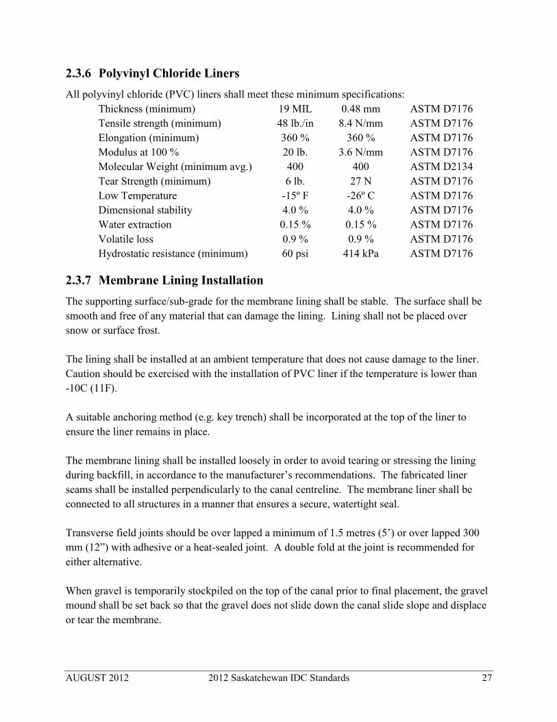
2.3.6 Polyvinyl Chloride Liners All polyvinyl chloride (PVC) liners shall meet these minimum specifications:
Thickness (minimum) 19 MIL 0.48 mm ASTM D7176 Tensile strength (minimum) 48 lb./in 8.4 N/mm ASTM D7176 Elongation (minimum) 360 % 360 % ASTM D7176 Modulus at 100 % 20 lb. 3.6 N/mm ASTM D7176 Molecular Weight (minimum avg.) 400 400 ASTM D2134 Tear Strength (minimum) 6 lb. 27 N ASTM D7176 Low Temperature -15º F -26º C ASTM D7176 Dimensional stability 4.0 % 4.0 % ASTM D7176 Water extraction 0.15 % 0.15 % ASTM D7176 Volatile loss 0.9 % 0.9 % ASTM D7176 Hydrostatic resistance (minimum) 60 psi 414 kPa ASTM D7176
2.3.7 Membrane Lining Installation The supporting surface/sub-grade for the membrane lining shall be stable. The surface shall be smooth and free of any material that can damage the lining. Lining shall not be placed over snow or surface frost. The lining shall be installed at an ambient temperature that does not cause damage to the liner. Caution should be exercised with the installation of PVC liner if the temperature is lower than -10C (11F). A suitable anchoring method (e.g. key trench) shall be incorporated at the top of the liner to ensure the liner remains in place. The membrane lining shall be installed loosely in order to avoid tearing or stressing the lining during backfill, in accordance to the manufacturer’s recommendations. The fabricated liner seams shall be installed perpendicularly to the canal centreline. The membrane liner shall be connected to all structures in a manner that ensures a secure, watertight seal. Transverse field joints should be over lapped a minimum of 1.5 metres (5’) or over lapped 300 mm (12”) with adhesive or a heat-sealed joint. A double fold at the joint is recommended for either alternative. When gravel is temporarily stockpiled on the top of the canal prior to final placement, the gravel mound shall be set back so that the gravel does not slide down the canal slide slope and displace or tear the membrane.

AUGUST 2012 2012 Saskatchewan IDC Standards 28
Backfill shall be placed by starting from bottom and proceeding towards the top. Construction measures shall be taken so that the lining is not displaced or damaged. In no case shall the gravel armour be dropped on the liner from a height exceeding 600 mm (24”). During installation, the liner shall be consistently monitored to ensure its integrity is maintained. Compaction of the backfill shall be completed in a manner that ensures the integrity of the liner. All rips or tears shall be repaired as part of the installation process.
2.4 CONCRETE LINED CANALS Concrete slip-lined canals are not approved for Saskatchewan rehabilitation projects. In rare cases, where a reinforced concrete, cast-in-place, canal is proposed, then the canal shall be designed as an individual reinforced concrete structure and the irrigation district shall request authorization prior to construction.
2.5 CANALS WITH EXPOSED LINERS Over the years, several materials have been installed as flexible or rigid surface liners. Some of these are high-density polyethylene, fibreglass, bitumen membrane, sulphur, butyl rubber, synthetic rubber (Hypalon), aluminum and asphalt. Some of these test installations have proved to be unsuccessful. Recently developed surface geo-membrane lining products have shown promise but have not yet proven to be successful over the long term. The methods used to install these materials differ and therefore, it is premature at this time to propose applicable standards. Where the designer feels the use of this type of material may be beneficial in a particular situation, the irrigation district shall request authorization to use a specific material prior to material purchase and installation.
2.6 WASTE WAYS Waste ways are large-capacity turnouts used to convey surplus water from storms, surge and other excess canal flows out of the canal system. Caution should be exercised in designing waste ways, particularly to avoid erosion and other un-desirable effects downstream. The entire length of the waste way channel needs to be considered in the design. All applicable provincial legislation and regulations shall be followed when designing and constructing waste ways.
2.6.1 Controlled Waste Ways Controlled waste way channels require some type of control gates. These gates should not be undershot gates since those structures are normally used for flow control, not level control. An overshot gate can be installed in a waste way to allow for both controlled and uncontrolled operation.

AUGUST 2012 2012 Saskatchewan IDC Standards 29
Waste way structure design can range from having no drop across the structure to having a significant amount of drop that require chute structures. Waste ways shall be designed as check structures, vertical check-drop structures or chute check-drop structures (see Chapter 4) but shall incorporate control gates.
2.6.2 Uncontrolled Waste Ways Uncontrolled waste ways are used to convey excess, unexpected flows such as those that occur due to storm events or systems shutting down upstream of the waste way. They may simply be a weir or a low spot in the canal bank that allows water to overflow whenever the water level exceeds a particular elevation. Uncontrolled waste ways are commonly required on canals if there are a number of closed pipelines upstream. If there is a power failure or another circumstance that causes many of the upstream users to suddenly shut down, there may be a large increase in flow at the waste way location.
2.6.3 Utilities Canal construction across or in close proximity to existing utilities shall only be undertaken when the special concerns of the utility are taken fully into account. The requirements of the governing authority of each utility shall be followed and need to be determined for each utility, such as railway, highway, municipal road, power line, gas and oil pipeline, telephone lines, fibre optic cables, associated irrigation district works etc. Proper notice of intended construction and of the commencement date of work, and arrangements for required inspection, supervision, and traffic control shall be provided in a complete and timely manner.

AUGUST 2012 2012 Saskatchewan IDC Standards 30
CHAPTER 3: PIPELINES Pipelines are enclosed conduits that convey water from a source to an outlet. Water flows in the pipeline because of gravity pressure (elevation changes), pumping pressure, or a combination thereof. Irrigation pipelines are considered transmission pipelines. Transmission pipelines are intended to convey large volumes of water from one location to another, usually at a relatively high flow velocity, and typically without loops or numerous and frequent lateral connections. They are classed as open or closed pipelines depending on whether or not water flows through an open channel at some point. Closed pipelines are sealed at the downstream end or there is a control at the outlet to ensure the pipeline remains completely full of water along its entire length. Open pipelines are open at the downstream end with the water exiting freely at atmospheric pressures, often into a canal, drain or reservoir.
3.1 Pipe Materials
The usual pipe materials are polyvinyl chloride (PVC), polyethylene (PE), pre-stressed or reinforced concrete pipe and certain types of steel pipe. Standard corrugated steel pipe (CSP) is permitted only in culvert and turnout applications. Specialized types of CSP may be used in low-pressure applications and heavier wall steel pipe may be used in high-pressure applications if adequately protected from corrosion. Design guidance for other pipe materials such as high density polyethylene (HDPE), steel, and concrete, can be obtained from the references in Appendix F.
3.1.1 Thermoplastic Pipe A number of different types of thermoplastic pipe materials are well suited to irrigation applications. Appendix F.2 contains a list of reference standards for the manufacturing and use of various thermoplastic pipes.
3.1.1.1 Polyvinyl Chloride Pipe
Polyvinyl chloride (PVC) pipe is used in Saskatchewan’s individual and district irrigation pipelines. PVC pipe shall be manufactured using resin PVC 1120 (cell classification 12454-B). The pipe standard dimension ratio (SDR) and the dimension ratio (DR) is the ratio of outside pipe diameter to wall thickness for thermoplastic pipes. The terms SDR and DR are considered to be identical and both are used interchangeably in this manual. PVC pipe with an SDR or DR greater than SDR 51 is not acceptable for use in Saskatchewan IRP projects. While the PVC resin type and SDR determines the pressure rating for all PVC pipe, the actual dimensions of the pipe depends on the dimensional standard used to manufacture the pipe. PVC pipe with the same SDR has the same pressure capacity and structural strength regardless of pipe

AUGUST 2012 2012 Saskatchewan IDC Standards 31
diameter. However, depending on its manufacturing standard, PVC pipe with the same SDR and nominal diameter (ND) may have significantly different outside diameter (OD). PVC pipe manufactured to iron pipe standard (IPS) differs from cast iron outside diameter (CIOD) pipe and from plastic irrigation pipe standard (PIP) pipe. For example, note the following:
SDR 41 PVC pipe has 350 mm (14”) ND and pressure rating of 690 (100 psi) but depending on the standard has these outside diameters:
350 mm (14”) IPS Pipe (ASTM D2241, CSA B-137.3) OD = 356 mm (14.00”) 350 mm (14”) CIOD Pipe (AWWA C905) OD = 388 mm (15.30”) 350 mm (14”) PIP Pipe (SCS 430-DD) OD = 363 mm (14.28”) 380 mm (15”) PIP Pipe (SCS 430-DD) OD = 388 mm (15.30”);
SDR 41 PVC pipe for 380 mm (15”) ND PIP pipe has the same OD as 350 mm (14”) ND CIOD pipe;
PVC pipe sizes smaller than 300 mm (12”) ND that are IPS pipe have larger OD than PIP pipe. However, PVC pipes greater than 300 mm (12”) ND, then the PIP pipe has a larger OD than IPS pipe; and
PVC pipe of 380 mm (15”) ND is available for PIP, but 380 mm (15”) ND is not manufactured as IPS or CIOD pipe.
Due to these significant variations, extra attention must be taken to ensure all fittings match with the pipe and are correctly sized.
3.1.1.2 PVC Ribbed Sewer Pipe
PVC ribbed sewer pipe is acceptable for open pipeline systems only. The pipe shall be manufactured according to ASTM Standard F794 Polyvinyl Chloride (PVC) Large Diameter
Ribbed Gravity Sewer Pipe and Fittings and other relevant ASTM standards quoted in ASTM F794. Pipe described under this standard and having a pipe stiffness of less than 320 kPa (45 psi) is not acceptable for use in Saskatchewan IRP projects.
3.1.1.3 High Density Polyethylene Pipe
High-density polyethylene (HDPE) pipe shall be manufactured in accordance with ASTM standard F714 and CSA standards B 137.0 and 137.1 from PE 3408 materials using resin compound with a minimum cell classification of 345464C in accordance with ASTM 2837. Pipe dimensions shall be in accordance with ASTM F714 and AWWA C906.
3.1.1.4 Lightweight Low-Pressure HDPE Pipe
Lightweight and low-pressure HDPE pipe, such as Weholite, may be used if designed and installed in accordance with the manufacturer’s recommendations for load bearings and for low-pressure systems, less than 105 kPa (15 psi). This large diameter, profile wall pipe is

AUGUST 2012 2012 Saskatchewan IDC Standards 32
manufactured according to ASTM F894: Specification for Polyethylene (PE) Large Diameter
Profile Wall Sewer and Drain Pipe and ASTM D3350: Specification for Polyethylene Plastics
Pipe and Fittings Material.
Pipe stiffness is critical for this type of pipe. For IRP applications, only pipe with a stiffness class of 160 or larger is acceptable. ASTM F894 defines a ring stiffness constant (RSC) as a measure of the pipe’s deformation resistance to diametrical point loading. A nominal pipe stiffness class (rating) of 160 corresponds to an RSC of 2.10 N per metre (144 lb. per ft.) of length.
3.1.2 Concrete Pipe Appendix F.4 contains a list of the reference standards used for the manufacturing and use of concrete pipe.
3.1.2.1 Pre-Stressed Concrete Cylinder Pipe
Pre-stressed Concrete Cylinder Pipe is specified under the AWWA Standard C301 and relevant AWWA and CSA standards are identify the material, level of construction, and tolerances. Hyprescon pipe meeting this standard is available as a lined cylinder pipe from 400 mm to 1,500 mm (16” to 60”) diameter and an embedded cylinder pipe from 1,050 mm to 3,600 mm (42” to 142”) diameter. Concrete placed in field, particularly for joint grout, shall be of uniform consistency, strength, and water to cement ratio as appropriate to resist degradation caused by sulphate and other soil or groundwater chemicals found at the installation depth of pipe.
3.1.2.2 Pre-Tensioned Concrete Cylinder Pipe
Reinforced concrete pressure pipe, steel cylinder type, is specified under the AWWA Standard C303 and relevant ASTM and CSA standards identify material, level of construction, and tolerances. Hyprescon pipe meeting this standard is available as a bar-wrapped concrete cylinder pipe from 350 mm to 1,350 mm (14” to 54”) diameter. Concrete placed in field, particularly for joint grout, shall be of uniform consistency, strength, and water-to-cement ratio and resistant to degradation caused by sulphate and other soil or groundwater chemicals found at the installation depth of pipe.
3.1.2.3 Non-Cylinder Reinforced Concrete Pressure Pipe
Non-cylinder reinforced concrete pressure pipe, AWWA C302, is used for low-pressure transmission lines in applications where the maximum operating pressure does not exceed 380 kPa (55 psi). This type of concrete pipe does not contain a steel cylinder, but has one or more reinforcing cages. It incorporates a welded steel bell and spigot joint-rings encased in the concrete wall of the pipe. The steel joint-rings, together with volumetrically sized rubber gaskets, ensure water tightness. The joint-rings have a zinc-metal protective coating that,

AUGUST 2012 2012 Saskatchewan IDC Standards 33
together with the joint grouting completed in the field, provide a level of corrosion resistance. Hyprescon manufactures C302 pipe from 750 mm to 3,660 mm (30” to 144”) diameter. Concrete pipe and concrete pipe joint mortar placed in field should have the strength, and a low water-to-cement ratio sufficient to resist degradation caused by sulphate and other soil or groundwater chemicals found at installation depth of the pipe.
3.1.2.4 Reinforced Concrete Low Head Pressure Pipe
The Reinforced Concrete Low Head Pressure Pipe shall be as specified under ASTM C361 and its metric companion C361-M. This low-head pressure pipe is suitable for internal static pressures ranging from 75 to 375 kPa (10 to 55 psi) and for installation in trenches up to 6 metres (20’) in depth. Early versions of this type of pipe had problems with the bell and spigot joints. Now the pipe joint has been improved by extending the reinforcement into the bell and spigot. This joint has been found to be satisfactory for low-pressure applications. Concrete pipe placed in field should have the strength and water-to-cement ratio sufficient to resist degradation caused by sulphate and other soil or groundwater chemicals found at installation depth of the pipe.
3.1.3 Corrugated Steel Pipe
3.1.3.1 Standard Corrugated Steel Pipe
Standard corrugated steel pipe (CSP), either galvanized, aluminized, or epoxy-coated may be used in culvert applications. Additional information is in Section 3.2.13 and Appendix F.3. Either circular, pipe-arch, or elliptical CSP be used in culvert applications.
3.1.3.2 Corrugated Steel Storm Sewer Pipe
Flexible spiral-rib steel pipe, such as circular Ultra Flow, is a suitable for open-flow (non-pressure) irrigation applications. The pipe has a hydraulically smooth inside wall with small external box-shaped ribs for stiffness. The pipe is available as galvanized, aluminized, or polymer-laminated steel. Aluminized steel is preferred where the soil has severe pH and high soil resistivity. For more demanding environments, polymer-laminated steel may be required.
Pipe is available in 1.6 mm, 2.0 mm, and 2.8 mm (0.063”, 0.079” and 0.110”) wall thickness and is connected with band type couplers, with or without gaskets. For Saskatchewan IRP projects, only couplers with gaskets shall be used.

AUGUST 2012 2012 Saskatchewan IDC Standards 34
3.2 PIPELINE DESIGN Irrigation pipelines shall be designed to provide adequate pressure and flow at each turnout of the pipeline. In addition, the design shall incorporate adequate surge pressure protection. The flow rate required for each section of the pipeline shall be determined by the procedures outlined in Chapter 1. The use of larger diameters and higher pressure rated pipe should be considered when additional pressure is needed at the farm turnouts or when significant long-term energy savings can be made in the operation of the overall system. When there is the possibility of direct energy savings to part of the system that is on the farm, then the potential irrigators should be consulted during the first phases of the pipeline design.
3.2.1 Hydraulic Grade Line The hydraulic grade line (HGL) for closed pipelines under all possible operating conditions, shall be above the top of the pipeline at all locations. When calculating HGL in irrigation pipelines, the minor losses - including velocity head, entrance and other losses - shall be taken into account by the designer. At the design operating conditions, the HGL at each pipeline turnout should be a minimum of 35 kPa (5 psi) greater than the static pressure required at the ground elevation.
3.2.2 Hydraulic Formulae
3.2.2.1 Closed Pipelines
Hydraulic calculations for closed pipelines shall use the Hazen-Williams formula:
V = 0.85ChR0.63S0.54
where V = average flow velocity (m/s) Ch = Hazen-Williams coefficient R = hydraulic radius of flow (m) S = hydraulic gradient (m/m) (note: R = ID/4 for a pipe flowing full)
Rearranging this formula to calculate the friction losses in any section of a closed pipeline(flowing full), results in the formula:
Hf = [1,650 (Q1.852)] / [(D4.870 (Ch1.852)]
where Q = flow rate (m3/s) Ch = Hazen-Williams roughness coefficient D = pipe inside diameter (ID) (metres) Hf = hydraulic gradient or friction losses (m/100 m)
AUGUST 2012 2012 Saskatchewan IDC Standards 35
3.2.2.2 Open Pipelines
Hydraulic calculations for open pipelines shall use Manning’s formula:
Q = (A/n)R2/3S1/2 where Q = flow rate (m3/s) n = Manning’s roughness coefficient A = cross sectional area of flow (m2) R = hydraulic radius (metres), S = hydraulic gradient (m/m) (note: R = cross sectional area of flow / wetted perimeter)
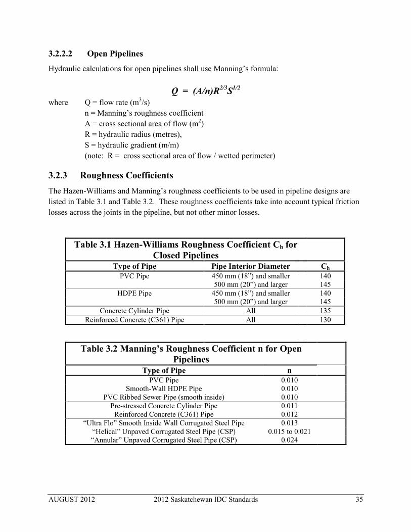
3.2.3 Roughness Coefficients The Hazen-Williams and Manning’s roughness coefficients to be used in pipeline designs are listed in Table 3.1 and Table 3.2. These roughness coefficients take into account typical friction losses across the joints in the pipeline, but not other minor losses.
Table 3.1 Hazen-Williams Roughness Coefficient Ch for Closed Pipelines
Type of Pipe Pipe Interior Diameter Ch PVC Pipe 450 mm (18”) and smaller 140
500 mm (20”) and larger 145 HDPE Pipe 450 mm (18”) and smaller 140
500 mm (20”) and larger 145 Concrete Cylinder Pipe All 135
Reinforced Concrete (C361) Pipe All 130
Table 3.2 Manning’s Roughness Coefficient n for Open Pipelines
Type of Pipe n PVC Pipe 0.010
Smooth-Wall HDPE Pipe 0.010 PVC Ribbed Sewer Pipe (smooth inside) 0.010
Pre-stressed Concrete Cylinder Pipe 0.011 Reinforced Concrete (C361) Pipe 0.012
“Ultra Flo” Smooth Inside Wall Corrugated Steel Pipe 0.013 “Helical” Unpaved Corrugated Steel Pipe (CSP) 0.015 to 0.021 “Annular” Unpaved Corrugated Steel Pipe (CSP) 0.024

AUGUST 2012 2012 Saskatchewan IDC Standards 36
3.2.4 Entrance Losses The hydraulic grade line (HGL) at the start of the pipeline shall be calculated in metric units as:
HGL = FSL – 0.30 – [V2/ (2g)] where HGL = elevation of the hydraulic grade line at the start of the pipeline (metres)
FSL = design full supply water level elevation in the canal (metres) V = the design flow velocity in the pipeline (m/s) g = gravitational acceleration constant (9.807 m/s2)
Formula for Calculating Entrance Losses using Imperial units:
HGL = FSL – 1.0 – [V2/ (2g)] where HGL = elevation of the hydraulic grade line at the start of the pipeline (ft.) FSL = design full supply water level elevation in the canal (ft.) V = the design flow velocity in the pipeline (ft./s) g = gravitational acceleration constant (32.2 ft./s2) This takes into account typical head loss across intake screens and/or trash racks, the inlet to the pipeline, and the energy converted to velocity head. The pipeline entrance shall be designed to ensure that inlet control does not govern or restrict the flow of water into the pipeline. A more detailed calculation may be required for particular inlet conditions.
3.2.5 Operating Pressures The pipeline operating pressures and any possible surge pressures shall be within the pressure rating and safety factor of the pipe being designed. The method used to determine the pressure rating (class) and safety factor may vary depending on the type of pipe and/or the standard to which the pipe is manufactured. At all points, the design of the pipeline should include calculations to determine the maximum operating pressure, the maximum static pressure and the calculated or estimated surge pressures that may occur. In pipelines pressurized by a pump, the maximum operating pressure may occur at any point along the pipeline. For gravity-fed pipelines, the maximum operating pressure typically is the static pressure at the lowest point of the pipeline. For PVC transmission pipelines, ASTM, CSA and AWWA C905 use a 2.0 factor of safety to determine the working pressure rating or class of the pipe. This safety factor relates to the long term, steady-state pressure capacity for the PVC of a particular SDR value. Surge calculations relate to the short term hoop strength of PVC and uses a 2.5 factor of safety to determine the short term pressure rating of the PVC for a particular pipe SDR.

AUGUST 2012 2012 Saskatchewan IDC Standards 37
The AWWA C900 PVC pipe standards, typically used for distribution pipeline systems, was revised in 2007 and specifies a 2.0 factor of safety to determine the working pressure class of the pipe. AWWA C900 and C905 PVC pipe manufactured in smaller than 100 mm (4”) diameter have different dimension ratios than pipe manufactured to ASTM, CSA or SCS standards and are not typically used in centre-pivot irrigation pipeline systems. The use of PVC for force main pipeline design standards, that uses a 2.0 factor of safety with respect to surge pressures, is not considered adequate for irrigation pipelines in Saskatchewan. The maximum operating pressure for PVC irrigation pipelines, accounting for working and surge pressures for transmission pipelines in conformity with AWWA C905 for different SDR pipe, are shown in Table 3.3a and Table 3.3b. Further details are shown in Figure 3.3.1a and Figure 3.3.1b. These standards maintain a minimum factor of safety of 2.0 relative to the maximum working pressure and a minimum factor of safety of 2.5 relative to the maximum potential surge pressure at the indicated water velocity.

AUGUST 2012 2012 Saskatchewan IDC Standards 38
Table 3.3a: PVC Pipe Pressure Ratings (PVC 1120 Resin): Metric Units
SDR & DR Ratio: Out Side Diameter to Wall Thickness
Pressure Ratings Standards PVC
Pressure Class
IRP Project Pressure Limits
Formulae To Calculate Allowable Working Pressure
(AWP)
Maximum Flow Velocity For
AWP Equal To PVC Pressure
Class
AWP (Operating plus Surge) at Velocity = 1.52
m/s
Pressure (kPa) Velocity (m/s) CSA
B-1373
AWWA C900 C905
SDR DR
(kPa) (kPa) (kPa) (m/s) (kPa) (kPa)
13.5 2170 2170 1.43 2133 If [V<1.43, 2170, 2828-(V*456)] 14.0 2110 2110 1.34 2035 If [V<1.34, 2110, 2720-(V*450)]
17.0 1720 1720 1.19 1592 If [V<1.19, 1720, 2207-(V*404)] 18.0 1620 1620 1.14 1470 If [V<1.14, 1620, 2070-(V*394)]
21.0 1380 1380 1380 1.05 1209 If [V<1.05, 1380, 1759-(V*361)] 25.0 1140 1140 1.04 978 If [V<1.04, 1140, 1483-(V*331)]
26.0 1100 1100 1100 0.96 919 If [V<0.96, 1100, 1414-(V*325)] 32.5 860 860 860 0.96 698 If [V<0.96, 860, 1138-(V*289)] 41.0 690 690 690 0.79 502 If [V<0.79, 690, 897-(V*259)] 51.0 550 550 550 0.56 319 If [V<0.56, 550, 689-(V*243)]
Note: PVC pipe with a SDR/DR greater than 51.0 is not approved for Saskatchewan IRP projects. Figures provided in Uni-Bell: 4th Ed: Handbook of PVC Pipe: Chapter V: Tables 5.5, 5.6, 5.8.

AUGUST 2012 2012 Saskatchewan IDC Standards 39
Table 3.3b: PVC Pipe Pressure Ratings (PVC 1120 Resin): Imperial Units
SDR & DR Ratio: Out Side Diameter to Wall Thickness
Pressure Ratings Standards
PVC Pressure
Class
IRP Project Pressure Limits
Formulae To Calculate Allowable Working Pressure
(AWP)
Maximum Flow Velocity For AWP
Equal To PVC Pressure Class
AWP (Operating plus Surge) at
Velocity = 5 ft./s
Pressure (psi) Velocity (ft./s) CSA
B-1373
AWWA C900 C905
SDR DR
(psi) (psi) (psi) (ft./s) (psi) (psi)
13.5 315 315 4.70 309 If [V<4.70, 315, 410-(V*20.2)] 14.0 305 305 4.55 296 If [V<4.55, 305, 395-(V*19.8)]
17.0 250 250 3.90 231 If [V<3.90, 250, 320-(V*17.9)] 18.0 235 235 3.75 213 If [V<3.75, 235, 300-(V*17.4)]
21.0 200 200 200 3.45 175 If [V<3.45, 200, 255-(V*16.0)] 25.0 165 165 3.40 142 If [V<3.40,165, 215-(V*14.7)]
26.0 160 160 160 3.15 133 If [V<3.15, 160, 205-(V*14.4)] 32.5 125 125 125 3.15 101 If [V<3.15, 125, 165-(V*12.8)] 41.0 100 100 100 2.65 73 If [V<2.65, 100, 130-(V*11.4)] 51.0 80 80 80 1.85 46 If [V<1.85, 80, 100-(V*10.8)]
Note: PVC pipe with a SDR/DR greater than 51.0 is not approved for Saskatchewan IRP projects. Figures provided in Uni-Bell, 4th Ed: Handbook of PVC Pipe: Chapter V: Tables 5.5, 5.6, 5.8.

AUGUST 2012 2012 Saskatchewan IDC Standards 40
Figure 3.3.1a Operating Pressures For PVC Transmission Lines (including surge pressure allowance): Metric Units
0
500
1000
1500
2000
2500
0.30 0.60 0.90 1.20 1.50 1.80 2.10
Allo
wab
le W
orki
ng P
ress
ure
(KPa
)
Velocity (m/s)
Allowable Working Pressure Design for PVC Transmission Pipelines Based on AWWA C905 (Metric Units)
SDR 21 Series 1380
SDR 26 Series 1100 SDR 32.5 Series 860
SDR41 Series 690
SDR 18 Series 1620
SDR 14 Series 2110
SDR 13.5 Series 2170
SDR 17 Series 1720
SDR 25 Series 1140
SDR 51 Series 550

AUGUST 2012 2012 Saskatchewan IDC Standards 41
Figure 3.3.1b Operating Pressures For PVC Transmission Lines (including surge pressure allowance): Imperial Units
0
50
100
150
200
250
300
350
1.00 2.00 3.00 4.00 5.00 6.00 7.00
Allo
wab
le W
orki
ng P
ress
ure
(psi
)
Velocity (ft/s)
Allowable Working Pressure Design for PVC Transmission Pipelines Based on AWWA C905 (Imperial Units)
SDR 21 Series 200
SDR 25 Series 160 SDR 32.5 Series 125
SDR 41 Series 100
SDR 18 Series 235
SDR 14 Series 305
SDR 13.5 Series 315
SDR 17 Series 250
SDR 26 Series 165
SDR 51 Series 80

AUGUST 2012 2012 Saskatchewan IDC Standards 42
3.2.6 Velocity Limits
3.2.6.1 Closed Pipelines
The likelihood of hydraulic transient (surge) pressures causing damage to the system dictates, to some extent, the maximum velocity allowed in the pipeline. Typical irrigation district pipelines with multiple turnouts, operating under normal conditions, seldom have large instantaneous changes in flow velocities, since the flow changes at different times at the different turnouts along the pipeline and since the open sprinkler nozzles provide greater dampening of the surge pressures than in totally enclosed pipelines. However, when a pipeline is supplied by electric powered pumps, there is the possibility of the pump station suddenly shutting down if the electricity supply is interrupted. The sudden pump stoppage at the main pump station or at the electrically powered centre-pivots results in significant surge pressures in the pipelines Where manually operated valves (e.g. butterfly valves) are located on the pipeline, the valves shall be equipped with threaded gear actuators or other equipment that prevent rapid opening or closing, thus reducing the possibility of damaging surge pressures. The maximum flow velocity for closed pipelines supplied by electric pumps should not be greater than 1.5 m/s (5 ft./s), unless surge protection equipment is incorporated into the pump station and pipeline. In gravity supplied pipeline systems, the surge pressures are seldom an issue on pipelines with multiple turnouts. However, if there are a large number of electrical pumps at turnouts connected to the pipeline and the pumps use electrical power from the same electrical source, there is the possibility of a power failure shutting down of all those pumps at the same time. This sudden power interruption produces surge pressures that need to be considered in the pipeline design. Where surge pressures can be excessive, surge protection can be provided by surge tanks, open standpipes, surge anticipator valves or other devices. The recommended maximum flow velocity for gravity-fed closed pipeline systems with multiple outlets, is 1.5 m/s (5 ft./s) and should be less than 2.5 m/s (8.2 ft./s). For short sections of the pipeline and when topography allows, water velocities up to 3.0 m/s (10 ft./s) are been found to operate acceptably, provided adequate valves are provided. The minimum flow velocity shall not be less than 0.6 m/s (2.0 ft./s) in order to prevent silt deposition in the pipeline. Economics generally dictate that the minimum velocity should be at least 1.0 m/s (3.0 ft./s).

AUGUST 2012 2012 Saskatchewan IDC Standards 43
3.2.6.2 Open Pipelines
The pipe diameters, and the corresponding velocities, for open pipelines are determined by the available slope and design flow rate. The minimum design velocity of flow shall be 0.6 m/s (2.0 ft./s) to avoid silt deposition in the pipeline.
3.2.7 Maximum Slope Pipelines shall not be set on slopes steeper than 3:1 (H:V) without pipe collars to resist creep.
3.2.8 Surge Protection Surge protection is not normally a concern with open pipeline systems. In closed gravity-fed pipelines, surge control is less of a concern than it is in pumped systems.
3.2.9 Surge Calculations The calculation of potential surge pressures can be a complicated procedure. The determination of the Maximum Surge Pressure based upon an instantaneous stoppage of flow is easier to calculate. In this situation, “instantaneous” means a time interval less than the time it takes for the pressure wave to move along the pipeline and back. The time of travel for the pressure wave in a long pipeline can be many seconds, or even minutes. Even though this method of calculation yields a conservative estimate of the surge pressure, in Saskatchewan the Maximum Surge Pressure for PVC Pipe shall be calculated and should not exceed the Allowable Working Pressure (AWP) shown in Tables 3.3a and 3.3b and Figures 3.3.1a and 3.3.1b. An estimate of the maximum surge pressure created in PVC pipelines due to a sudden change in velocity can be calculated according to Table 3.4.
Table 3.4: Maximum Surge Pressure for PVC Pipe (Adapted from Table 5.8 – Uni-bell PVC Pipe Association: Handbook of
PVC Pipe & Table 4 – ANSI/ASAE Standard Number S376.2) Pipe SDR (or DR)
Surge pressure per 0.3 m/s (1 ft./s) of sudden change in flow velocity
kPa psi 11.0 155 22.5 13.5 14.0
139 137
20.2 19.8
17.0 18.0
124 120
17.9 17.4
21.0 25.0
110 101
16.0 14.7
26.0 99 14.4 32.5 88 12.8 41.0 79 11.4 51.0 74 10.8

AUGUST 2012 2012 Saskatchewan IDC Standards 44
Values presented in Table 3.4 permit an order magnitude approximation and are not a substitute for the detailed calculations. The designer should use appropriate surge pressure protection for other pipe materials, such as HDPE, steel, and concrete. In Saskatchewan if surge pressures are not known, then pipe velocities should be maintained at 1.5 m/s (5 ft./s) or less and the working pressure should not exceed the maximum allowable working pressure for the particular PVC pipe pressure rating recommended for PVC transmission pipeline AWWA C905 standards as shown in Figures 3.3.1a and 3.3.1b. If those limits are met, surge pressures should not be an issue. If these values are exceeded, detailed surge pressures shall be calculated and adequate surge prevention provided.
3.2.10 Corrosion Prevention All pipes shall be made of either non-corroding or corrosion protected material. Wherever possible, fittings below ground should be made of the same material as the pipeline. Metal fittings below-ground shall be protected with an adequate coating of a non-corrosive barrier coating or cover. Concrete placed in field as corrosion protection should be of uniform consistency, strength, and water-to-cement ratio that will resist degradation caused by sulphate and other soil and groundwater chemicals found at the installation depth of pipe. The barrier coating of metallic fittings shall be equivalent to priming the metal with petroleum paste and wrapping the fitting with a minimum of two layers of petroleum tape, such as Denso. Irregular surfaces shall be primed with petroleum paste, voids filled with petroleum mastic and covered with two layers of petroleum tape. All below ground restraints and anchors shall be protected from corrosion and electrically separated from other metal fittings by tape wrapping. Metal fittings should also have adequately sized sacrificial anodes permanently attached to the fitting. Anodes should be checked on a regular basis to determine when they need to be replaced. As an alternative, cathodic protection by an impressed electrical current system may be provided.
3.2.11 Turnout Sizing The design flow rate for turnouts to individual parcels or to a group of parcels shall be based on Table 1.1. Turnout pipe and valve size shall be determined by using the maximum pressure in the supply pipeline at the point of the turnout. The turnout sizes are shown in Table 3.5.
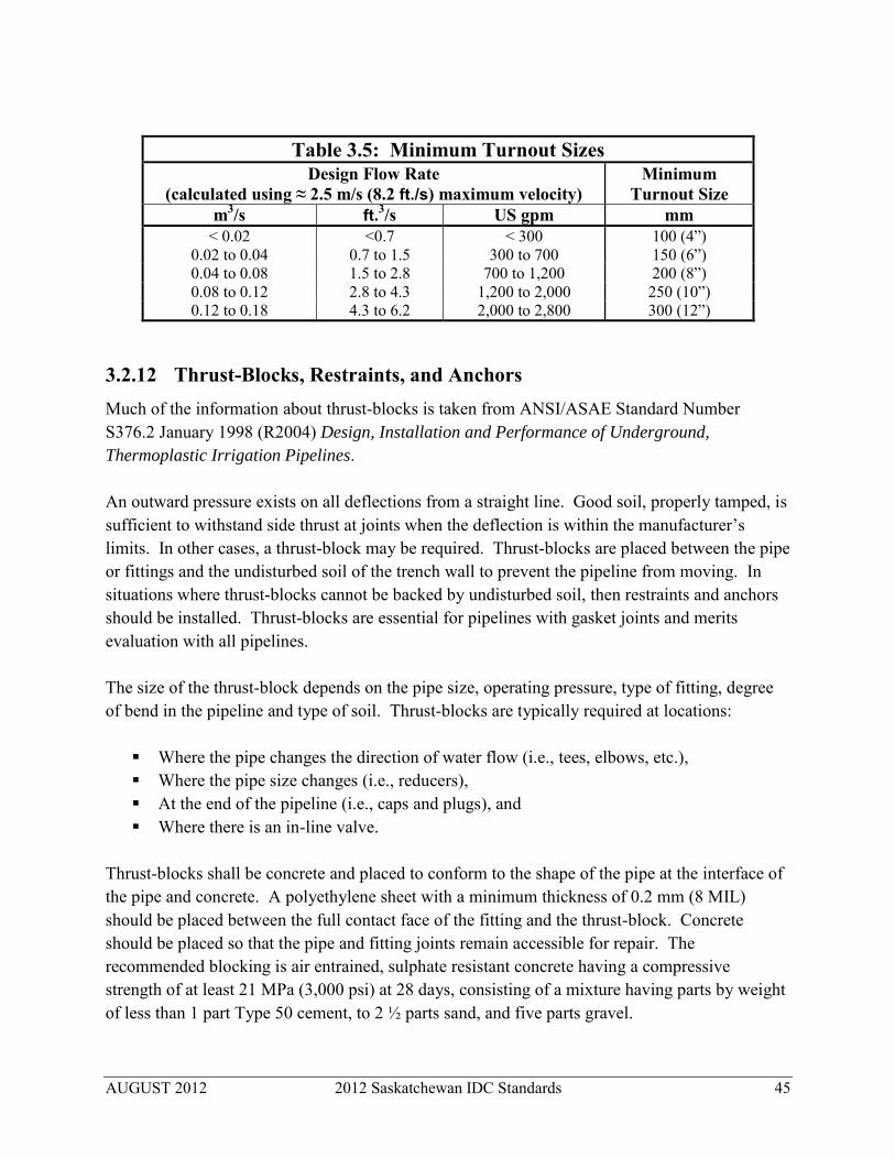
AUGUST 2012 2012 Saskatchewan IDC Standards 45
Table 3.5: Minimum Turnout Sizes Design Flow Rate
(calculated using ≈ 2.5 m/s (8.2 ft./s) maximum velocity) Minimum
Turnout Size m3/s ft.3/s US gpm mm
< 0.02 <0.7 < 300 100 (4”) 0.02 to 0.04 0.7 to 1.5 300 to 700 150 (6”) 0.04 to 0.08 1.5 to 2.8 700 to 1,200 200 (8”) 0.08 to 0.12 2.8 to 4.3 1,200 to 2,000 250 (10”) 0.12 to 0.18 4.3 to 6.2 2,000 to 2,800 300 (12”)
3.2.12 Thrust-Blocks, Restraints, and Anchors Much of the information about thrust-blocks is taken from ANSI/ASAE Standard Number S376.2 January 1998 (R2004) Design, Installation and Performance of Underground,
Thermoplastic Irrigation Pipelines. An outward pressure exists on all deflections from a straight line. Good soil, properly tamped, is sufficient to withstand side thrust at joints when the deflection is within the manufacturer’s limits. In other cases, a thrust-block may be required. Thrust-blocks are placed between the pipe or fittings and the undisturbed soil of the trench wall to prevent the pipeline from moving. In situations where thrust-blocks cannot be backed by undisturbed soil, then restraints and anchors should be installed. Thrust-blocks are essential for pipelines with gasket joints and merits evaluation with all pipelines. The size of the thrust-block depends on the pipe size, operating pressure, type of fitting, degree of bend in the pipeline and type of soil. Thrust-blocks are typically required at locations:
Where the pipe changes the direction of water flow (i.e., tees, elbows, etc.), Where the pipe size changes (i.e., reducers), At the end of the pipeline (i.e., caps and plugs), and Where there is an in-line valve.
Thrust-blocks shall be concrete and placed to conform to the shape of the pipe at the interface of the pipe and concrete. A polyethylene sheet with a minimum thickness of 0.2 mm (8 MIL) should be placed between the full contact face of the fitting and the thrust-block. Concrete should be placed so that the pipe and fitting joints remain accessible for repair. The recommended blocking is air entrained, sulphate resistant concrete having a compressive strength of at least 21 MPa (3,000 psi) at 28 days, consisting of a mixture having parts by weight of less than 1 part Type 50 cement, to 2 ½ parts sand, and five parts gravel.

AUGUST 2012 2012 Saskatchewan IDC Standards 46
The bearing surface of the thrust-block should be in a direct line with the major force created by the pipe or fitting (See Figure 3.1 and Appendix D). The thrust-block’s earth-bearing surface should be against the undisturbed soil of a solid trench wall, with only the simplest of forms used. Anchors rods should not be smaller than M15 (5/8”) diameter rebar and double wrapped with petroleum tape to prevent corrosion. Examples of thrust-blocks, restraints and anchors are shown as in Figure 3.1.
90° Bend
Tee
Pipe Thrust-Blocks
90° Elbow with Restraints
Tee with Restraints
Pipe Restraints
45° Bend with Anchors
Valve with Anchors
Pipe Anchors
Figure 3.1: Example Thrust-Blocking, Restraints and Anchors

AUGUST 2012 2012 Saskatchewan IDC Standards 47
3.2.13 Pipeline Drains When the pipelines are installed above the frost line, provision shall be made for draining pipelines at all low points. Where turnouts or risers are connected to pipelines installed below the frost line, provision shall be made to drain these turnouts or risers. If drainage cannot be provided by gravity, provision shall be made to remove water from the pipeline at the end of the irrigation season by “pigging”, pumping, or a combination of methods. Wherever possible, gravity drains should be used rather than pumped drains.
3.2.14 Culverts Culverts using corrugated steel pipe (CSP), are often part of irrigation water conveyance systems. Helical CSP is specified under the CSA standard CAN 3-G401-M81. The American Iron and Steel Institute’s (AISI) Handbook of Steel Drainage and Highway Construction
Products, the National Corrugated Steel Pipe Association, Corrugated Steel Pipe Institute and other relevant agencies quoted by the AISI’s handbook provide additional information. Galvanized steel has traditionally been used in culvert applications. Aluminized CSP may be used as an alternative to galvanized steel. The minimum thickness of coatings for CSP used in culvert applications should be as shown in Table 3.6.
Table 3.6: Minimum CSP Wall Thicknesses Nominal Pipe Diameter
Minimum Coated Thickness
Galvanized Steel Aluminized Type 2 Steel
Less than 600 mm (24”)
1.6 mm (0.063”)
1.6 mm (0.063”) 600 – 1,200 mm (24”- 48”) 2.0 mm (0.079”) 2.0 mm (0.079”)
Greater than 1,200 mm (48”) 2.8 mm (0.11”) 2.8 mm (0.11”)
CSP shall not be used where leakage may cause a problem and is not acceptable for closed pipelines. When designing culverts for use in irrigation systems, the Manning’s roughness coefficients shown in Table 3.7 shall be used:

AUGUST 2012 2012 Saskatchewan IDC Standards 48
3.3 INLETS, FITTINGS, TURNOUTS AND OUTLETS Pipeline fittings are usually made of the same material as the pipeline. They may be PVC, PVC/fibreglass, concrete, HDPE, steel or other suitable material. If there is potential for corrosion, adequate corrosion protection must be used with the fitting (see Section 3.2.10).
3.3.1 Settling Ponds Settling ponds may be provided at the inlet of a closed pipeline to reduce the amount of sediment entering the pipeline. The intake to the settling pond should be located in such a way that the water has to travel the furthest distance possible to the pipeline inlet, thus giving the sediment time to settle. Where possible, the inlet into the settling pond should be at one end and perpendicular to the long dimension of the settling pond. The intake to the pipeline should be on the opposite bank of the settling pond at the other end. Stoke’s Law may be used to determine a minimum length for settling out larger particles (e.g. sand), but it is seldom practical to design the settling pond long enough to settle out smaller particles. Where it is not possible to satisfy the above criteria, a concrete panel diffuser baffle can be an effective means of causing particulate matter to travel the maximum distance and settle before reaching the pipeline inlet. The baffle should be located approximately 3.0 metres (9.6’) downstream of the pond intake in order to diffuse flow. Rock gabion baskets may also be used to reduce the aquatic weeds, algae or sediment entering the pipeline. Extra construction measures must be taken to ensure that any pond lining is not adversely affected. The intake to the pipeline should be located upwind from the prevailing wind direction so that trash floating on the water surface may be blown away from the pipeline inlet. Where this is impractical, the intake should be screened.
Table 3.7: Manning’s Roughness Coefficients – CSP Culverts Type of CSP CSP Diameter Manning’s “n”
Helical CSP
68 mm x 13 mm (2.7” x 1/2”) Corrugations
Annular CSP
68 mm x 13 mm (2.7” x 1/2”) Corrugations
300 to500 mm (12-20”)
0.015
600 to 900 mm (24-36”) 0.018 900 to 1,200 mm (36-48”) 0.020
> 1,200 mm (48”)
All diameter sizes
0.021
0.024

AUGUST 2012 2012 Saskatchewan IDC Standards 49
3.3.2 Trash Racks All inlets shall be provided with trash racks for safety and to keep large objects from entering the pipeline. For closed pipelines, the openings shall be narrower than 25 mm (1”). Provision shall be made for the removal and cleaning of the racks and screens. In addition, settling ponds and/or fine screens may be used in conjunction with trash racks. Finer screens may be specified by irrigation districts according to district policy. Usually fish protection requirements do not apply in irrigation district canals and drains, however for rivers, reservoirs and lakes, the regulations of the fishery and environmental agencies need to be followed.
3.3.3 In-Line Fittings and Valves In-line fittings should be made of the same material as the pipeline. In cases where steel or other metallic fittings need to be used in a PVC or PE pipeline, adequate corrosion protection shall be provided (see Section 3.2.10). Isolation valves shall be located wherever pipelines owned by the irrigation district are connected to privately owned works. For on-farm turnouts, the isolation valve may be located at any practical location on the turnout. Isolation valves may also be located at other locations in the pipeline system to facilitate ongoing operations during the season including repair, maintenance and/or pressure testing. Manually operated valves (e.g. butterfly valves) should be equipped with slow opening gear in order to lengthen the time required to open or close the valve, thereby reducing the corresponding surge pressures.
3.3.4 Turnouts Underground steel fittings should be used for turnouts. Where turnouts are connected to the pipeline by a tee, the tee outlet should be within 45º of the horizontal. A thrust-block is necessary at the tee connections. For 100 mm (4”) and larger turnouts, there shall be a butterfly valve with a gear operator, or other slow-closing valve, to control the flow at the delivery end of the turnout. Turnouts and risers shall be adequately protected from damage due to livestock, wildlife, or equipment.

AUGUST 2012 2012 Saskatchewan IDC Standards 50
Steel turnouts shall be protected against corrosion below ground (See Section 3.2.10) and painted or coated above ground. Any scratches or damage to the corrosion protection shall be repaired by re-application of the protective coating. Consideration should be given to flow metering at the turnout, irrespective of whether or not the flow meter is part of the initial pipeline installation. If the pipeline turnout is directly connected to the pumping unit, the irrigator shall include a check valve on the pump discharge pipe. The check valve shall be designed to close, without slamming shut, at the point of zero velocity, before the water flow can reversal and enter into the pipeline.
3.3.5 Air Valves Air release and vacuum relief valves shall be installed at all summits, at the ends and at the entrance of pipelines in order to allow air to enter and exit the pipeline. Combination air-vacuum release valves that provide both functions may be used. An air vent, for air entry and release, should be located at every gravity pipeline inlet and within one pipe diameter from the pipe entrance. To ensure adequate air release the vent piping may begin with a short section of larger diameter pipe (See Figure 3.4). The top of the air vent should be equipped with a 90 degree elbow or 180 degree bend and a bird screen.
Figure 3.4: Air Vent Configuration
Valves having large orifices are required at the end of all closed pipelines to exhaust large quantities of air when the pipeline fills and to allow air to enter the pipeline in order to prevent a vacuum when the pipeline drains. Valves that continuously release entrapped air may have smaller orifices and are required at all pipeline summits.

AUGUST 2012 2012 Saskatchewan IDC Standards 51
At each closed pipeline turnout larger than 150 mm (6”), there shall be an air-vacuum valve installed very close to and upstream of the turnout valve. If the hydraulic grade line is less than 1.0 metre (3.3’) above the turnout outlet, it may be necessary to set the air-vacuum valve below the elevation of the turnout outlet. When closed pipelines deliver water to booster pumping units, the HGL shall not be less than 20 kPa (3 psi) above the pump before it is operating (therefore eliminating the need for priming). On start-up, there is the possibility that negative pressure can exist at the inlet to the pump (outlet of the turnout); therefore air vents must be located and operated so that damage to the pipeline is prevented while still keeping the pump primed. A slow-opening control valve should be installed downstream of a booster pump.
Air valves are susceptible to damage from freezing whenever the pipeline is full and the air temperature could fall below zero (spring and fall). Therefore, adequate protection from freezing needs to be considered with all air valve installations. This may also apply to some fittings attached to turnouts (e.g. closed ball valves).
3.3.6 Energy Dissipaters Where water exits a pipeline into an open channel at a velocity greater than 2.5 m/s (8 ft./s), an outlet structure is recommended to be built in order to dissipate the excess energy and prevent excessive erosion. Hanging baffles, concrete manholes or other devices may be used as an energy dissipater. Where water velocities exceed 3.65 m/s (12 ft./s) and flows are greater than 0.5 m3/s (0.014 ft.3/s), then the hanging baffle structure is recommended at the outlet. For these higher flows, the hanging baffle structure shall be either cast-in-place reinforced concrete or precast reinforced concrete. Riprap rock on bedding gravel or filter cloth shall be provided downstream of the energy dissipater as specified in Chapter 4.
3.4 PIPELINE INSTALLATION
3.4.1 General Requirements: PVC and HDPE Pipe All thermoplastic pipes fall under the category of flexible pipe and must be installed in a manner that ensure minimal vertical deflection. The pipe and soil interaction is often critical to the load- carrying capacity of flexible pipes. The terms shown in Figure 3.5 are used throughout this section.

AUGUST 2012 2012 Saskatchewan IDC Standards 52
Figure 3.5: Pipeline Installation Terms
The manufacturer’s recommendation shall be followed for assembling pipes. Pipe pullers are recommended for joining gasket joints. The use of power equipment such as a backhoe bucket should be allowed for joint assembly, only if approved by the manufacturer. Where a backhoe is used to assemble pipe, the bell of the previously installed pipe shall be restrained to ensure there is no movement of any previously installed lengths of pipe. In this situation, construction measures must be taken to prevent force from damaging to the joint or fitting. Flanged joints may be used to connect pipe to metal fittings or concrete structures. The manufacturer’s recommendation shall be followed for making flanged joints. When pipe is purchased a well engineered installation plan should be in place that would include planning for design, handling, storage, field inspections and compaction monitoring, acceptance testing and other aspects of quality control. Problems such as high water table and unsuitable backfill material should be anticipated. Checklists and identification of milestones would be useful for the installers and inspectors.
3.4.1.1 Trench Width
Trench excavations must be stable and meet the requirements of the most recent edition of The
Saskatchewan Occupational and Safety Act and the Occupational Health and Safety Regulations.
The minimum trench width shall be wide enough to allow backfill material to flow easily around the sides of the pipe and, also provide for the adequate compaction of pipe haunches, depending on the material and type of compaction equipment. The maximum trench width should be 400

AUGUST 2012 2012 Saskatchewan IDC Standards 53
mm (16”) on each side of the pipe. This width shall be maintained up to the top of the pipe. The required compaction shall be completed within the initial backfill zone for the full trench width.
3.4.1.2 Trench Bottom and Bedding
The pipe shall be laid on firm stable soil that is free of water. Rocks larger than 40 mm (1 ½“), boulders, frozen lumps, etc. shall be removed prior to pipe installation. When the pipe is provided with bell and spigot joints, bell holes should be excavated in the bedding material to provide uniform support along the pipe and allow for the unobstructed assembly of the joint. Construction procedures should ensure the bell hole is no larger than necessary to accomplish proper joint assembly. Bedding is required if the natural trench material is unstable, organic soil, excessively wet, or excavated in bedrock. In these cases, the trench bed shall be over-excavated and re-filled with at least 100 mm (4”) of suitable granular bedding material (sand or gravel) having a maximum size of less than 40 mm (1 ½”). Bedding material shall be placed in a balanced sequence of backfilling in order to provide uniform adequate support along the entire pipe. Material should be placed in lifts of not more than 150 mm (6”) thickness without compaction, when compaction of material is required. At no time should there be a difference of more than one lift of material between one side of the pipe and the other. Under wet and unstable soil conditions, geo-textile materials may be used with the bedding. Water in the trench should be eliminated prior to backfilling. In some cases, granular material having a maximum size less than 40 mm (1 ½”) (with or without geo-textile material) may be used to provide a firm support for the pipe. Impervious plugs (e.g. clay, lean concrete) shall be installed every 100 metres (330’) along the trench in order to prevent water from moving along the granular fill and to assist in locating leaks.
3.4.1.3 Pipe Assembly
Pipe sections should be assembled and joined in trench. However if this is not practical, pipe sections may be joined above ground and placed in the trench in a manner that does not damage the pipe. The pipe sections must be carefully lowered, not dropped, into the trench using adequately sized slings. The spigot end of the pipe joint shall not be inserted beyond the insertion line marked on the pipe. Prior to backfilling, the depth of insertion of the spigot at each joint shall be re-checked to ensure it is correctly aligned and secured.
3.4.1.4 Deflection and Bending
The pipe shall be installed in a manner that ensures excessive deflection in the joints and excessive bending of the pipe does not occur during installation. Bending stresses should be avoided and at no time should the pipe be blocked or braced to hold a bend. The pipe maximum

AUGUST 2012 2012 Saskatchewan IDC Standards 54
permissible deflection and minimum pipe bending radii must not exceed the manufacturer’s recommendations.
3.4.1.5 Pipe Haunches and Backfill
Compaction of the fill material under the pipe haunches is important to prevent deforming the pipe in its transverse cross section. Most soils and gravels are acceptable for fill under the haunches. Material used for fill under the haunches shall flow easily around the sides of the pipe and also under the pipe. No organic soils, frozen earth, debris or rocks larger than 40 mm (1 ½”) shall be allowed to contact the pipe. Imported material used for fill under the haunches shall not exceed 25 mm (1”) diameter. Compaction of the fill under the haunches shall be to 90 per cent Standard Proctor Density. Soil fill shall not be over-compacted under the haunches to the extent that causes pipe displacement. Most soils are suitable for initial backfill provided they are free from organic material, rocks, stones or clods greater than 40 mm (1 ½ ”) diameter. Backfill soil around and to the top of the pipe shall be compacted in a balanced sequence and compacted to 90 per cent Standard Proctor Density. Material should be placed in lifts of not more than 150 mm (6”) thickness without compaction. At no time should there be a difference of more than one lift of material between one side of the pipe and the other. The backfill material shall be sufficiently compacted under and on each side of the pipe in order to provide support free from voids. Construction shall not deform, displace, or otherwise damage the pipe. Compaction directly over the pipeline, especially when using larger compaction equipment, must be avoided. Over-compaction can result in pipe deflection. Top soil shall be replaced over the top of the trench excavation and mounded. The final backfill should be compacted as necessary to minimize final settlement. Extra granular material, and compaction may be required under centre-pivot or linear system wheel tracks.
3.4.1.6 Minimum Earth Cover
The minimum cover above the pipeline shall be 1.0 metre (39” or 3.3’).
3.4.1.7 Tracer Wire or Tape
To facilitate locating the pipeline in the future, tracer wire or metallic identification tape shall be placed above the pipe (either on the pipe, within or on top of the initial backfill) and brought to the surface at each end of the pipeline. The wire and tape shall be placed at a depth at least 800 mm (32”) below the final ground elevation. After installation and before final backfill, the wire/tape shall be tested electrically to confirm electrical continuity.

AUGUST 2012 2012 Saskatchewan IDC Standards 55
3.4.1.8 Pressure and Leak Testing
Pressure and leak testing may be conducted on PVC pipelines before they are put into service. Typical criteria for pressure and leak testing are:
Use a hydrostatic test pressure of 200 kPa (30 psi) at the highest point of the pipeline (the inlet of the pipeline for most gravity pipelines).
Do not exceed the Pressure Rating for the SDR pipe shown in Tables 3.3a and 3.3b at any other point in the pipeline.
Use a two-hour period for the test. Fill the line slowly with water, at a velocity not to exceed 0.3 m/s (1.0 ft./s), calculated as
if the pipe is flowing full. Make adequate provision for air release while filling, taking care to bleed all entrapped
air from the pipelines. Slowly build up to the test pressure. At the end of the two hours, refill the line with water to bring the pipeline back up to the
test pressure. To pass the test, the makeup volume of water required to bring the pipeline back up to
test pressure shall be less than:
L = [ND(P0.5)] / 130,000 where L = volume of makeup water (litres per hour) N = number of pipe lengths D = nominal pipe diameter (mm) P = test pressure (kPa)
Formula for Calculating Pipeline Leakage using Imperial units:
To pass the test, the makeup volume of water required to bring the pipeline back up to test
pressure shall be less than:
L = [ND(P0.5)] / 7,400 where L = volume of makeup water (US gal/hr) N = number of joints in the tested line (pipe and fittings) D = nominal pipe diameter (inches) P = test pressure (psi)
In cases where the pipe is not PVC or the pipe manufacturer has published pressure or leakage test criteria different from these standards, then the manufacturer’s criteria can be used.

AUGUST 2012 2012 Saskatchewan IDC Standards 56
3.4.2 Alternative Procedures: Smaller, High Pressure PVC Pipe In cases where the PVC pipe is SDR41 or less (namely, PVC with 690 kPa (100 psi) or greater pressure rating) and a nominal diameter of 300 mm (12”) or less is used, the installation procedures outlined in this Section 3.4.2 may be used, rather than the requirements outlined in Section 3.4.1.
3.4.2.1 Trench Construction
Trenches may be dug using wheel or chain type trenchers. The width of the trench needs only to be sufficient to allow the backfill material to flow around the sides of the pipe to ensure there are no voids in the pipe haunches. Excessively wide trenches should be avoided. The stability of the trench walls and the nature of the backfill material are critical in determining if this alternative installation procedure is practical. Backfill material can be native material provided it is free from lumps, rocks, and frozen material. During backfilling, the backfill material must be able to flow around the pipe. Pipe should be assembled in the trench; however, if this is not practical, the pipe’s spigot end shall be inserted the correct depth into each bell above ground. Then the pipe shall be carefully lowered, not dropped, into the trench. The insertion depth shall be checked at each joint after the pipe is lowered into the trench and prior to backfilling.
3.4.3 Special Considerations: HDPE Pipe High density polyethylene (HDPE) pipe, including Weholite pipe, generally requires more specialized backfill and compaction considerations than PVC pipe. The pipe and soil interaction is critical to the load-carrying capacity of HDPE pipe. Installation specifications shall conform to the manufacturer’s recommendations and the field inspection of the installation should be continuous. Most HDPE pipes are joined in the field by a thermal fusion or extrusion welding of the HDPE pipe ends. All fused joints have a strength equal or exceeding the pressure rating of the pipe. Fusing the joints are specialized operations requiring a thermal machine and trained individuals. Often it is necessary to have the pipe manufacturer supply and operate the fusing machine. Due to the uniqueness of the installation process, additional issues may be important such as water entering the trench and the period of time that the trench needs to open. Also thrust- blocks may not be required in some situations because the HDPE pipe sections are welded together.

AUGUST 2012 2012 Saskatchewan IDC Standards 57
Granular backfill must be used in all situations of installation of HDPE pipe. Installation of HDPE pipe in soft soil should be avoided. If HDPE pipe must be used in a soft soil area, then a filter cloth and washed granular material must be incorporated. In wet groundwater conditions, it may be necessary to use washed rock [100 per cent passing a 20 mm (3/4”) sieve] as bedding. This bedding should continue to 400 mm (16”) above the pipe invert. Bedding, initial backfill and fill material under the haunches shall consist of a combined coarse-fine granular filter material [100 per cent passing a 40 mm (1 ½”) sieve, 5 to 25 per cent passing a 0.5 mm (0.02”) sieve] compacted to a minimum 90 per cent of Standard Proctor Density. The minimum bedding thickness is 150 mm (6”) and the filter material shall be placed to the top of the pipe. Impervious plugs (e.g. clay, lean concrete) shall be installed every 100 metres (330’) along the trench to prevent water from moving along the granular fill and to assist in locating leaks,. The minimum and maximum allowable trench widths for HDPE are:
Minimum Trench Width = 1.25 * OD + 300 mm (12”) Maximum Trench Width = Minimum Trench Width + 450 mm (18”)
Additional installation recommendations are found in ASTM D2321 Standard Practice for
Underground Installation of Thermoplastics Pipe for Sewers and Other Gravity Flow
Applications.
3.4.4 Special Considerations: Corrugated Steel Storm Sewer Pipe Corrugated steel storm sewer pipe, such as Ultra-Flo, performs as a flexible compression ring under soil load and usually these pipes are installed in a trench. Installation shall follow the manufacturer specified minimum and maximum heights of cover, depending on the diameter and metal thickness. Bedding preparation is critical to both pipe performance and service life. The bedding shall be well-graded granular material, free of rock formations, protruding stones, frozen lumps, roots or other foreign material that could cause unequal settlement. Bedding and backfill materials must meet the requirements of the CSP installation specification outlined in ASTM A798. The installation shall be completed according to ASTM A796, paragraph 17.2.3 and ASTM A798 for certain sizes or wall thicknesses of pipe.
3.4.5 Special Considerations: Rigid Concrete Pipe The installation of rigid concrete pipe shall be as described in Section 3.4.1, except as otherwise noted in this section. Appendix F.4 contains references regarding the manufacture and installation of rigid concrete pipe.

AUGUST 2012 2012 Saskatchewan IDC Standards 58
The most common rigid pipes used for irrigation are: Reinforced Concrete Low Head (C361) pipe, Pre-stressed Concrete Cylinder (C301) pipe, and Pre-tensioned Concrete Cylinder (C303) pipe [with pipe diameters ≤ 400 mm (16”)].
Manufacturer’s recommendations shall be followed when placing and joining all concrete pipes.
3.4.5.1 Trench and Bedding
Trench bedding is the key factor in ensuring adequate performance of rigid pipes. Bedding and bedding angle determines how the external load is distributed on the pipe. AWWA, ASTM and the manufacturer's literature provide similar recommendations for bedding and bedding angles. The pipe shall be laid on firm stable soil, free of water or rocks larger than 40 mm (1.5”). Extra excavation under each bell and spigot joint must be provided at the joint in order to ensure uniform pipe support. Bedding is required primarily to bring the trench bottom up to grade. Placement shall provide uniform support under the pipe. The minimum density shall be 95 per cent of Standard Proctor Density. Where an unstable sub-grade condition is encountered, the trench bed shall be over excavated and replaced with suitable material. Within 100 mm (4”) of the pipe, the minimum density of the bedding shall be 95 per cent of Standard Proctor Density.
3.4.5.2 Pipe Assembly
All pipes shall be assembled according to the manufacturer’s specifications. Special grouting is required for the C301 Pre-stressed Concrete Cylinder Pipe joint to protect its metal parts against corrosion. Joining pipes and compacting the backfill soil shall be completed without displacing the pipe gaskets.
3.4.5.3 Backfill, Pipe Haunches and Compaction
Cohesive or granular soils are suitable for backfill, provided the backfill is free of rocks larger than 40 mm (1.5”). Compaction can be achieved by tamping, rolling, vibrating, or a combination of the three. The space between the trench wall and the pipe, starting at the bottom and up to 40 per cent of the pipe outside diameter, shall be compacted to a minimum of 95 per cent of Standard Proctor Density. With concrete pipe, compaction of the haunches is not required for pipe support but for uniform density against lateral shift and subsequent soil settlement above the pipe. The minimum density for compaction of the haunches shall be 95 per cent of Standard Proctor Density. Initial backfill shall be compacted up to 300 mm (12”) above the pipe to at least 95 per cent of Standard Proctor Density.

AUGUST 2012 2012 Saskatchewan IDC Standards 59
Material for final backfill may be bladed and machine compacted to 80 to 85 per cent of Standard Proctor Density in order to minimize settlement. Material should be placed in lifts of not more than 150 mm (6”) thickness without compaction.
3.4.6 Special Considerations: Semi-Rigid Concrete Pipe Pre-tensioned concrete cylinder pipe shall be manufactured in accordance with AWWA C303. It is considered semi-rigid at diameters greater than 400 mm (16”). The installation of semi-rigid concrete pipe shall be the same as that of rigid concrete pipe (Section 3.4.5) except as noted in this section. The performance of semi-rigid pipe against external load is governed by both its inherent strength and from the support of the surrounding soil as it deflects. Therefore, the most important factors in installation are trench bed foundation, backfill and its degree of compaction. Lateral support provided by the soil is a major factor in determining the performance of semi-rigid pipe in resisting external loads. Details on the installation of pre-tensioned concrete cylinder pipe for diameters greater than 400 mm (16”) is given in AWWA manual M9, Concrete
Pressure Pipe.
3.4.7 Utilities Pipeline construction across or in close proximity to existing utilities shall only be undertaken once the special concerns of the utility have been fully taken into account. The requirements of the governing authority of each type of utility shall be followed and need to be determined for each type of utility, such as railway, highway, municipal road, power line, gas and oil pipeline, telephone lines, fibre-optic cables, associated irrigation district works etc. Proper notice of intended construction, notification of the commencement of work, and arrangements for required inspection, supervision, and traffic control shall be provided in a complete and timely manner.
AUGUST 2012 2012 Saskatchewan IDC Standards 60
Chapter 4: CONSTRUCTION AND HYDRAULIC STRUCTURES
Chapter 4 provides construction guidelines and references the detailed hydraulic structure designs described in Chapter 4 of the 2010 Alberta Irrigation Rehabilitation Program Design
and Construction Standards Manual. The primary intent of this chapter is to cover the general construction, structural, and hydraulic requirements for cast-in-place concrete hydraulic structures where the design maximum flow is not greater than 100 m3/s (3,500 ft.3/s) and the maximum change in elevation does not exceed 15 metres (50’). Metric units must be used for equations presented in Chapter 4; imperial units are provided only for reference. There may be specific situations that require structures that are an exception to these standards. In these cases, it is the responsibility of the designer to ensure these structures perform in an acceptable manner over the long-term life of the structure Cast-in-place concrete hydraulic structures shall be designed and appropriate drawings stamped and signed by a Professional Engineer (P. Eng.) or a Engineering Licensee registered with the Association of Professional Engineers and Geoscientists of Saskatchewan (APEGS). In circumstances of an Engineering Licensee, the professional’s registration with APEGS must specify that their defined scope of practise includes the design of irrigation structures. Reference standards are generally those used by the structural building industry of Canada and the USA, modified to meet hydraulic and irrigation requirements and criteria with emphasis on safety for the public and operators. The reference standards applicable to concrete structures are listed in Appendix F.1. Other reference materials related to the design of hydraulic structures are listed in Appendix F.5.3 and F.5.4.
4.1 CAST-IN-PLACE CONCRETE STRUCTURES Reinforced cast-in-place concrete hydraulic structures form an integral part of the conveyance systems for irrigation. In canal systems, they include checks, drops, check-drops, turnouts, weirs, waste ways, reservoir inlet and outlet structures and tail water outlet structures. For pipelines, they include inlet and outlet structures, including impact baffles. This standard does not specifically cover the use of proprietary materials or methods of construction. Quality of construction shall meet the minimum requirements included in CAN/CSA-A23.1-M Concrete Materials and Methods of Concrete Construction, CAN/CSA-A23.2M Methods of Test for Concrete and this standard.

AUGUST 2012 2012 Saskatchewan IDC Standards 61
4.2 STANDARD FEATURES: CAST-IN-PLACE CONCRETE STRUCTURES
4.2.1 Concrete Properties All cast-in-place concrete shall have the properties:
Minimum concrete compressive strength for structural concrete of 30 MPa (4,350 psi) at 28 days;
Minimum concrete compressive strength for foundation concrete (mud slab) of 20 MPa (2,900 psi) at 28 days;
All concrete be sulphate resistant; and All concrete have four per cent to seven per cent air entrainment.
In addition, concrete placed in field should be of a strength, and water to cement ratio as appropriate to resist degradation caused by sulphate and other soil and groundwater chemicals found at the depth of the structure installation.
4.2.2 Reinforcing Steel Reinforcing steel shall be 400 MPa (58,000 psi) (Grade 400) deformed bars meeting the requirements of CSA G30.18-M. Reinforcing Steel shall be placed in accordance with CSA 23.1 and guidelines of the Reinforcing Steel Manual of Standard Practise.
4.2.3 Structural Freeboard For inline structures the structural freeboard for inline structures shall be installed:
For 0 to 30 m3/s (0 to 1,000 ft.3/s) freeboard shall be according to the canal hydraulics design requirement (Section 2.1.4) plus 100 mm (4”).
For 30 to 60 m3/s, (1,000 to 2,000 ft.3/s) freeboard shall be according to the canal hydraulics design requirement plus 200 mm (8”).
For 60 to 100 m3/s (2,000 to 3,500 ft.3/s), freeboard shall be according to the canal hydraulics design requirement plus 300 mm (12”).
4.2.4 Cut-Off and Curtain Walls Cut-off walls shall be provided across the entire width of the structure. Structures longer than 15 metres (50’) in the direction of flow may be provided with intermediate cut-off walls. The minimum depth of the cut-off wall shall be 900 mm (36”) below the bottom of the floor slab. Where curtain walls are necessary at the sides of stilling basins, the minimum depth shall be 900 mm (36”) below the bottom of the floor slab.

AUGUST 2012 2012 Saskatchewan IDC Standards 62
All cut-off and curtain walls shall be excavated and cast against earth unless excessive cut-off depth prevents this. Where soft soils are encountered and the vertical excavation collapses, the soft soils shall be excavated and replaced with soils with a high clay content (CI or CL) compacted to 98 per cent Standard Proctor Density. The cut-off and curtain walls shall then be excavated and cast against this material.
4.2.5 Stoplogs and Flashboards Provision for stoplogs and flashboards shall be incorporated where appropriate for maintenance and emergencies. It should be noted that large bay openings in structures cannot be closed with stoplogs, but require a fabricated steel bulkhead. It is often more practical to eliminate the stoplog slots on larger inline structures and use upstream earth or inflating rubber plugs for water control if repairs are required during the operating season.
4.2.6 Safety All hydraulic structures can be a potential safety hazard. Appropriate safety devices such as guardrails, handrails, operating decks and chain-link fencing shall be provided to keep the public and the operators safe. Warning signs shall be installed where significant or unusual hazards are present in the canal system. Safety provisions and signage shall conform, as a minimum, to the requirements of the most recent edition of The Saskatchewan Occupational Health and Safety
Act and the Occupational Health and Safety Regulations. Where a structure presents an extreme safety hazard (no possibility of escape), safety ladders, floating booms, safety nets, cables, trash racks or other devices shall be installed immediately upstream.
4.2.7 Sub-Slab Drainage Structures subjected to hydrostatic uplift pressures shall be provided with adequate sub-slab drainage, or sufficient mass to resist uplift. Additional information on sub-slab drainage is contained in Sections 4.3.4 and 4.3.6 and shown in Figures 4.4 and 4.6 (chute check-drop structures and chute drop structures).
4.2.8 Concrete Cover The specified concrete cover for reinforcement steel shall be:
For principal reinforcement, No. 35 or smaller, in beams, girders columns and piles: 50 mm (2”)
For ties, stirrups and spirals: 40 mm (1.5”) For all concrete cast against earth: 75 mm (3”)

AUGUST 2012 2012 Saskatchewan IDC Standards 63
For slabs, walls joists, shells and folded plates, No. 20 or smaller: 30 mm (1 ¼”)
4.2.9 Soft Soil Subgrade Where soft soil subgrades are encountered, the area below the width and length of the structure shall be over-excavated and backfilled with clay controlled soils (CI or CL in Figure 4.1). Where only a portion of the foundation is soft, that area shall be over-excavated and backfilled with soil with a high clay content (CI or CL) compacted to 98 per cent Standard Proctor Density.
4.2.10 Sub-Slab Insulation Sub-slab insulation shall not be used due to the risk of pipe failure.
4.2.11 Foundation Concrete (Mud Slab) Foundation concrete is recommended below all reinforced structural floors to provide a clean working surface for the placement of reinforcing steel and structural concrete. Foundation concrete shall be used to overlay and protect granular filter materials when used beneath a reinforced structural floor. Foundation concrete shall be a minimum of 50 mm (2”) thick, and shall have the concrete properties stated in Section 4.2.1.
4.2.12 Minimum Thickness of Slabs and Walls The minimum floor slab thickness shall be 350 mm (14”) and the slab shall be monolithic with walls for water-tightness and structural strength. Minimum cut-off and curtain wall thickness shall be 300 mm (12”). When cast against earth, the minimum thickness shall be 400 mm (16”).
4.2.13 Expansion Joints The number of expansion joints shall be kept to a minimum. Joints should be spaced at approximately 15 metres (50’) intervals except where a key pour is used. Where a key pour is used, the spacing can be increased to 30 metres (100’). A key pour consists of a 1.0 metre long section of wall and slab that is poured at least seven days after the upstream and downstream portions of the structure are poured. Reinforcing steel shall be continuous through the key to maintain full structural strength of the wall and slab. A key pour shall extend across the full width of the structure. A key pour of only a wall section or only a slab section is not permissible.

AUGUST 2012 2012 Saskatchewan IDC Standards 64
Where expansion joints are necessary, they shall be constructed with a 25 mm (1”) thick low-density foam spacer through the full width of the joint. A PVC water stop, large bulb type, shall be cast securely into both sections of the concrete at the centreline of the joint to ensure water-tightness. The water stop shall be effective for all changes of length caused by the variation of outside temperatures.
A PVC or other adequate dirt-stop shall be cast securely into both sections of the expansion joint on the backfilled side of the wall. A galvanized steel or stainless steel cover plate shall be cast into the upstream wall and floor concrete to protect the expansion joint. The cover plate shall not be fastened to the downstream wall and floor concrete but shall be free to slide with any expansion and contraction.
4.2.14 Steel Components and Corrosion Protection Many of the structures covered here require steel trash racks and other steel parts. Steel parts are to be protected as follows:
Steel parts, which are embedded in concrete and exposed to water or air, shall be protected against corrosion by galvanizing;
Buried steel components shall be coated with a bituminous compound, coal-tar tape wrapped, double wrapped with “Denso” tape and mastic, or sprayed with a 2 mm (0.08”) thick coating of polyurethane and then protected with sacrificial anodes;
Bolted steel parts above water shall be painted or galvanized. It is recommended that steel parts bolted or set on the structure and partly immersed in water be galvanized.
4.2.15 Soil Loads and Hydrostatic Pressure Many soils in southern Saskatchewan have a high clay content that classifies, structurally, as CL or CI soils (see Figure 1.4). They are called clays, clay tills, silty clays or silty clay tills. Hydraulic structures should be backfilled with native soils or imported soils that classify as CL or CI soils if available. Where structures are backfilled with CH, CL-ML, ML, sands, gravels or any soils below the “A” line shown on Figure 4.1, the design must be adjusted accordingly.

AUGUST 2012 2012 Saskatchewan IDC Standards 65
Figure 4.1: Plasticity Chart (from Lambe & Whitman Soil Mechanics)
The abbreviation used in Figure 4.1 are:
CL - Clay, Low plasticity soils CI - Clay, Intermediate (medium) plasticity soils
CH - Clay, High plasticity soils
ML - Silt, Low plasticity soils
MH - Silt, High plasticity soils
OL - Organic, Low plasticity soils
OH - Organic, High plasticity soils
Unless actual soil tests indicate otherwise, all structures shall be designed for: Dry Soil Unit Weight of 22 kN/m3 (140 lb./ft.3) Coefficient of Lateral Earth Pressure of 0.5, Saturation to canal FSL level, and Backfill specified as 95 per cent Standard Proctor Density.

AUGUST 2012 2012 Saskatchewan IDC Standards 66
4.2.16 Seepage Path All structures shall be designed with adequate seepage cut-off walls and sidewalls in order to prevent pipe failure at the structure due to differential head between the water level upstream and downstream of the structure. Path length requirements and resultant cut-off depths and sidewall sizes shall be determined using Lane’s Weighted Creep Ratio (WCR). This requires calculation of WCR on the centreline of the structure as well as around the side of the structure. The weighted creep distance (L) shall be the sum of the vertical creep distances (steeper than 45o) plus one-third of the horizontal creep distances (flatter than 45o). The head (H) shall be the difference between the upstream FSL elevation and the downstream bed elevation. The weighted creep ratio is:
WCR = L / H And shall be:
At least 2.0 for CI classified clay-controlled soils. At least 2.5 for CL classified clay-controlled soils.
4.2.17 Standard Riprap Sizes Riprap shall be well graded within each size range and with a gradation that falls completely within the envelopes defined as:
Size I Riprap:
Effective Particle Size Per Cent (%) Passing by Mass 300 mm (12”) 100 200 mm (8”) 30 to 70 175 mm (7”) 20 to 50 125 mm (5”) 0
This corresponds to Alberta Transportation Zone 6A Riprap.
Size II Riprap: Effective Particle Size Per Cent (%) Passing by Mass
500 mm (20”) 100 400 mm (16”) 50 to 90 300 mm (12”) 20 to 50 200 mm (8”) 5 to 20 150 mm (6”) 0 to 2
This is similar to Alberta Transportation Zone 6B Riprap.
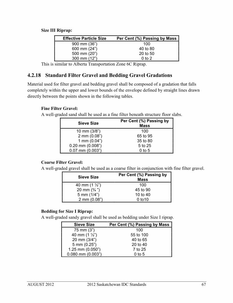
AUGUST 2012 2012 Saskatchewan IDC Standards 67
Size III Riprap:
Effective Particle Size Per Cent (%) Passing by Mass 900 mm (36”) 100 600 mm (24”) 40 to 80 500 mm (20”) 20 to 50 300 mm (12”) 0 to 2
This is similar to Alberta Transportation Zone 6C Riprap.
4.2.18 Standard Filter Gravel and Bedding Gravel Gradations Material used for filter gravel and bedding gravel shall be composed of a gradation that falls completely within the upper and lower bounds of the envelope defined by straight lines drawn directly between the points shown in the following tables.
Fine Filter Gravel: A well-graded sand shall be used as a fine filter beneath structure floor slabs.
Sieve Size Per Cent (%) Passing by Mass
10 mm (3/8”) 100 2 mm (0.08”) 65 to 95 1 mm (0.04”) 35 to 80
0.20 mm (0.008”) 5 to 25 0.07 mm (0.003”) 0 to 5
Coarse Filter Gravel: A well-graded gravel shall be used as a coarse filter in conjunction with fine filter gravel.
Sieve Size Per Cent (%) Passing by Mass
40 mm (1 ½”) 100 20 mm (¾ ”) 45 to 90 5 mm (1/4”) 10 to 40
2 mm (0.08”) 0 to10
Bedding for Size I Riprap: A well-graded sandy gravel shall be used as bedding under Size I riprap.
Sieve Size Per Cent (%) Passing by Mass 75 mm (3”) 100
40 mm (1 ½”) 55 to 100 20 mm (3/4”) 40 to 65 5 mm (0.25”) 20 to 40
1.25 mm (0.050”) 7 to 25 0.080 mm (0.003”) 0 to 5

AUGUST 2012 2012 Saskatchewan IDC Standards 68
Bedding for Size II and Size III Riprap: Well-graded sand, gravel and cobblestones shall be used as bedding under Size II and Size III riprap.
4.3 CAST-IN-PLACE INLINE STRUCTURES This section covers the hydraulic design of check structures, vertical check-drop structures, chute check-drop structures, vertical drop structures and chute drop structures. Every attempt should be made to provide sufficient length to the structure so that downstream wing walls are not required. The use of downstream wing walls is not recommended. Inline structures shall incorporate measures to ensure that the upstream portion completely drains from the structure at the end of the irrigation season. Where the downstream stilling basin is not depressed below the canal bed, the end sill shall incorporate a drainage slot.
4.3.1 Structural Freeboard For inline structures the structural freeboard shall be installed:
For 0 to 30 m3/s (0 to1,000 ft.3/s) – according to the canal hydraulics design requirement (Section 2.1.4) plus 100 mm (4”).
For 30 to 60 m3/s (1,000 to 2,000 ft.3/s) – according to the canal hydraulics design requirement plus 200 mm (8”).
For 60 to 100 m3/s (2,000 to 3,500 ft.3/s) – according to the canal hydraulics design requirement plus 300 mm (12”).
4.3.2 Check Structures Check structures are used in a canal to control upstream water level at partial flow. Check structures have no change in invert elevation across the structure. The spacing of check structures along the canal is covered in Section 2.1.10. Where there is drop in the invert, then the structure shall be designed as a vertical check-drop or a chute check-drop structure.
Effective Particle or Sieve Size
Per Cent (%) Passing by Mass
250 mm (10”) 100 200 mm (8”) 40 to 100 150 mm (6”) 20 to 50 75 mm (3”) 5 to 30
40 mm (1 ½”) 0 to 5

AUGUST 2012 2012 Saskatchewan IDC Standards 69
For canal flows less than 2.0 m3/s (70 ft.3/s), the upstream water level shall be maintained with stoplogs, overshot gates (drop leaf or Langemann gate) or Lopac style gates. For flows 2.0 m3/s (70 ft.3/s) or greater, overshot gates shall be used. Undershot gates shall not be used in check structures. Hydraulic design of check structures shall use the methodology identified in C.D. Smith’s text Hydraulic Structures. The methodology identifies structure width, basin length, basin block placement and sizing. For pure check structures, with an adequate basin length, basin blocks shall not be used. The remainder of the hydraulic sizing shall be determined using the methodology identified in V. T. Chow’s text Open-Channel Hydraulics. This method is outlined below and the resulting structure is shown in Figure 4.2. Structure Width: Check structures shall have parallel side walls and the width (W) of the structure shall be:
W = 2.3 (Q 0.5) [m] where Q = the canal design flow [m3/s].
W shall be rounded to the nearest 500 mm (20”). This may result in a structure being wider or narrower than the design bed width of the canal. Discrepancies shall be eliminated by transitioning the earthwork upstream and downstream of the structure. Corners: The upstream headwall shall transition into the structure sidewalls using:
A curved wall with a minimum radius of 300 mm (12”), or A bevelled, chamfered edge of at least 300 mm (12”).
Sill Height: When an overshot gate is used, it shall be set on a concrete sill and the height of the sill shall be:
HS = 0.2 D1 [m] where D1 = normal canal depth at canal design flow (Q) [m].
HS shall be rounded off to the nearest 50 mm. In no case shall HS exceed 0.3 D1. If stoplogs or Lopac gates are used, the sill can be eliminated. When a Langemann gate is used, the gate will be positioned with the sill of the gate at 0.2 D1 when the gate is in the full down position.

AUGUST 2012 2012 Saskatchewan IDC Standards 70
Drop Leaf Gate: Where a drop leaf gate is used, the length of the leaf shall be:
LL = 0.924 D1 [m] The above formula applies when the sill height (HS) = 0.2 D1. The drop leaf gate shall be horizontal in its full-open position (maximum Q) and at 60 degrees from the horizontal in its full-closed position (zero Q). The gate hoist shall be placed such that the hoist cable lines up with the lift points of the gate at full up and full down positions. Six air vents, three on each side of the gate, shall be installed to supply air to the underside of the gate at all gate positions. These are shown in Figure 4.2. Depth of Water over the Gate or Stop Log for Stilling Basin Design:
H = 0.5 D1 [m] In a check structure at zero flow and full checking, there is no flow through the structure and no energy dissipation. As the flow increases and the gate drops lower, energy dissipation commences and increases to a maximum at approximately H = 0.5D1. As the flow increases further, downstream canal backwater starts to flood-out the hydraulic jump and reduces the energy dissipation in the structure. At design flow, the overshot gate is full open and no energy dissipation occurs in the structure. Approach Length: For check structures where the flow is greater than 3.0 m3/s (100 ft.3/s), there shall be an approach section between the upstream wing walls and the discharge point of the sill. This length shall be at least:
Le = 2 H = D1 [m] When an overshot gate is used, the horizontal length of the gate, in its full down position shall count toward the required approach length. The length of the drop leaf gate is usually sufficient to meet this criterion. Discharge Coefficient for Stilling Basin Design: The discharge coefficient for gates varies with the position of the gate. For overshot gates the discharge coefficient corresponding to the previously calculated H is:
Cg = 2.26 For stoplogs, the discharge coefficient is:
CS = 1.83

AUGUST 2012 2012 Saskatchewan IDC Standards 71
Structure Design Flow for Stilling Basin Design: When an over shot gate is used, the design flow used for sizing the structure shall be: QS = Cg (W - 0.2 H) H
1.5 [m3/s] When stoplogs are used, the design flow used for sizing the structure shall be: QS = CS (W - 0.2 H) H
1.5 [m3/s] Note: QS is the flow through the structure that generates the longest basin length requirement.
It is less than the canal design flow (Q) in the canal upstream of the check structure. Unit Flow: q = QS / W [m2/s] Drop: Z = 0.5 D1 [m] Drop Number:
D = q 2 / (g Z 3)
where g = 9.807 m/s2
Gate Leaf Horizontal Length: Lg = [LL
2 – (0.3 D1 )2 ] 0.5 [m] Nappe Travel Distance: Ld = 4.3 Z D 0.27 [m]
Stilling Basin Length: Lb = 3 d2 [m] Hydraulic Jump (Sub-Critical) Conjugate Depth: d2 = 1.66 Z D 0.27 [m] End Sill Height:
Height = d2 / 10 or 0.20 m (8”),whichever is greater.

AUGUST 2012 2012 Saskatchewan IDC Standards 72
Riprap and Bedding Gravel: Riprap shall be placed downstream of the check structure to protect against erosion. Riprap shall extend a minimum of three times the structure width downstream of the structure (bed and side slopes). In some cases, the combined effect of wave action and eddy action will make it necessary to extend the side slope riprap further than three times the width (C. D. Smith). The riprap and bedding gravel shall be recessed into the sub-grade so that the top of the riprap is even with the bed and side slopes of the canal. All riprap shall be placed on bedding gravel. Size and thickness of the riprap and bedding gravel shall be as follows: Canal Design Riprap Riprap Bedding Flow (Q) Material Thickness Material Thickness 0 to 15 m3/s Size I 300 mm (12”) See Section 4.2.18 150 mm (6 “) (0 to 530 ft.3/s) 15 to 100 m3/s Size II 500 mm (20”) See Section 4.2.18 300 mm (12”) (530 to 3,500 ft.3/s)

AUGUST 2012 2012 Saskatchewan IDC Standards 73
Figure 4.2: Check Structure

AUGUST 2012 2012 Saskatchewan IDC Standards 74
4.3.3 Vertical Check-Drop Structures Vertical check-drop structures are used in a canal to control upstream water level at partial flow and to provide grade control in the bed slope of the canal. The location of vertical check-drop structures is determined by topography and the need for checking upstream turnouts. Vertical check-drop structures shall be used where there is a significant change in hydraulic grade line across the structure, but that change is less than 2.0 metres (6’). Where the drop is 2.0 metres (6’) or greater, the structure shall be designed as a chute check-drop structure. For canal flows less than 2.0 m3/s (70 ft.3/s), upstream water level shall be maintained with stoplogs or overshot gates (drop leaf or Langemann-style gate). For flows 2.0 m3/s (70 ft.3/s) or greater, overshot gates shall be used. Undershot gates (such as radial gates) shall not be used in vertical check-drop structures. Hydraulic design of vertical check-drop structures shall use the methodology identified in C.D. Smith’s text Hydraulic Structures. The methodology identifies structure width, basin length, basin block placement and sizing. The remainder of the hydraulic sizing shall use the methodology identified in V. T. Chow’s text Open-Channel Hydraulics. This method outlined below and the resulting structure is shown in Figure 4.3. Structure Width: Vertical check-drop structures shall have parallel side walls and the width of the structure shall be:
W = 2.3 (Q 0.5) [m] where Q = the canal design flow [m3/s].
W shall be rounded to the nearest 500 mm (20”). This may result in a structure being wider or narrower than the design bed width of the canal. Discrepancies shall be eliminated by transitioning the earthwork upstream and downstream of the structure. Corners: The upstream headwall shall transition into the structure sidewalls with:
A curved wall with a minimum radius of 300 mm (12”), or A bevelled, chamfered edge of at least 300 mm (12”).

AUGUST 2012 2012 Saskatchewan IDC Standards 75
Sill Height: When a drop leaf gate is used, it shall be set on a concrete sill and the height of the sill shall be:
HS = 0.2 D1 [m] where D1 = normal canal depth at canal design flow (Q) [m].
HS shall be rounded off to the nearest 50 mm (2”). In no case shall HS exceed 0.3 D1. If stoplogs are used, the sill can be eliminated. When a Langemann gate is used, the gate will be positioned with the sill of the gate at 0.2 D1 when the gate is in the full down position. Drop Leaf Gate: Where a drop leaf gate is used, the length of the leaf shall be:
LL = 0.924 D1 [m] The above formula applies when the sill height (HS) = 0.2 D1. The drop leaf gate shall be horizontal in its full-open position (maximum Q) and at 60 degrees from the horizontal in its full-closed position (zero Q). The gate hoist shall be placed such that the hoist cable lines up with the lift points of the gate at full up and full down positions. Six air vents, three on each side of the gate, shall be installed to supply air to the underside of the gate at all gate positions when Z1 is less than 500 mm (20”). These are shown in Figure 4.3. Only two air vents, one on each side of the gate, are required when Z1 is equal to or greater than 500 mm (20”). These vents will be positioned to supply air to the gate when the gate is in the horizontal position. Depth of Water over the Gate or Stop Log: H = D1 (0.5 + 0.15 Z1) [m]
where Z1 = upstream bed elevation – downstream bed elevation [m]. Approach Length: For check structures where the flow is greater than 3.0 m3/s (100 ft.3/s), there shall be an approach section between the upstream wing walls and the discharge point of the sill. This length shall be:
Le = 2 H [m]

AUGUST 2012 2012 Saskatchewan IDC Standards 76
When an overshot gate is used, the horizontal length of the gate, in its full down position shall count toward the required approach length. The length of the drop leaf gate is usually sufficient to meet this criterion. Discharge Coefficients: For overshot drop-leaf gates, varying from 0º to 60º above horizontal, the discharge coefficient (Cg) is:
Cg= 1.7273 + 0.055775 Ø - 0.0019932 Ø2 + 0.000032310 Ø3 - 0.00000020321 Ø4 where
Ø = sin - 1 [(D1 – HS – H ) / LL ] = gate angle above horizontal position [degrees] For overshot Langemann gates, the above formula applies with Ø being the angle of the upper leaf with the horizontal. For stoplogs the discharge coefficient is:
CS = 1.83 Structural Design Flow: When an over shot gate is used, the design flow used for sizing the structure shall be:
QS = Cg (W - 0.2 H) H 1.5 [m3/s] When stoplogs are used, the design flow used for sizing the structure shall be:
QS = CS (W - 0.2 H) H 1.5 [m3/s] Note: QS is the flow through the structure that generates the longest basin length requirement.
It is less than the canal design flow (Q) upstream of the check structure. Unit Flow: q = QS / W [m2/s] Drop: Z = D1 – H + Z1 [m] Drop Number: D = q2 / (g Z3)
where g = 9.807 m/s2

AUGUST 2012 2012 Saskatchewan IDC Standards 77
Gate Leaf Horizontal Length: Lg= [LL
2 – (D1 - HS – H)2] 0.5
Nappe Travel Distance: Ld = 4.3 Z D 0.27 [m] Supercritical Depth: d1 = 0.54 Z D 0.425 [m] Hydraulic Jump (Sub-Critical) Conjugate Depth: d2 = 1.66 Z D 0.27 [m] Stilling Basin Length: Lb = 3d2 [m] Check Downstream Canal Depth: For proper hydraulic performance, conjugate depth (d2) must be less than the downstream normal canal depth (D2). D2 shall be calculated using Manning’s roughness = 0.020 to ensure that adequate tail water exists. If D2 is less than d2, then the basin of the vertical drop structure must be depressed such that the conjugate depth water elevation is equal to or lower than the normal tail water depth calculated with Manning’s roughness = 0.020. This will require recalculation of the structure dimensions. Basin Block Sizing:
Height = d1 or d2 / 8 or 0.25 m (10”), whichever is greater. Width = d1 or d2 / 8 or 0.25 m (10”), whichever is greater. Spacing = d1 or d2 / 8 or 0.25 m (10”), whichever is greater.
End Sill Height: Height = d2 / 10 or 0.20 m (8”), whichever is greater.

AUGUST 2012 2012 Saskatchewan IDC Standards 78
Riprap and Bedding Gravel: Riprap shall be placed downstream of the vertical check-drop structure to protect against erosion. Riprap, of the size specified below, shall extend a minimum of three times the structure width downstream of the structure (bed and side slopes). The riprap and bedding gravel shall be recessed into the subgrade so that the top of the riprap is even with the bed and side slopes of the canal. All riprap shall be placed on bedding gravel. Size and thickness of the riprap and bedding gravel shall be as follows: Canal Design Riprap Riprap Bedding Flow (Q) Material Thickness Material Thickness 0 to 15 m3/s Size I 300 mm (12”) See Section 4.2.18 150 mm (6”) (0 to 530 ft.3/s) 15 to 100 m3/s Size II 500 mm (20”) See Section 4.2.18 300 mm (12”)
(530 to 3,500 ft.3/s)

AUGUST 2012 2012 Saskatchewan IDC Standards 79
Figure 4.3: Vertical Check-Drop Structure

AUGUST 2012 2012 Saskatchewan IDC Standards 80
4.3.4 Chute Check-Drop Structures Chute check-drop structures are used in a canal to control upstream water level at partial flow and to provide grade control in the bed slope of the canal. The location of chute check-drop structures is determined by topography and the need to check the water level at the height needed by upstream turnouts. Chute check-drop structures shall be used where the change in the hydraulic grade line across the structure is 2.0 metres (6’) or greater. Where the drop is less than 2.0 metres (6’), the structure shall be designed as a vertical check-drop structure. For canal flows less than 2.0 m3/s (70 ft.3/s), upstream water level shall be maintained with stoplogs or overshot gates (drop leaf or Langemann-style gate). For flows 2.0 m3/s (70 ft.3/s) or greater, overshot gates shall be used. Undershot gates (such as radial gates) shall not be used in chute check-drop structures. Hydraulic design of chute check-drop structures shall use the methodology followed in C.D. Smith’s text Hydraulic Structures. This method outlined below and the resulting structure is shown in Figure 4.4. Structure Width: Chute check-drop structures shall have parallel side walls and the width of the structure shall be:
W = 2.3 (Q 0.5) [m] where Q = the canal design flow [m3/s].
W shall be rounded to the nearest 500 mm (20”). This may result in a structure being wider or narrower than the design bed width of the canal. Discrepancies shall be eliminated by transitioning the earthwork upstream and downstream of the structure. Corners: The upstream headwall shall transition into the structure sidewalls with:
A curved wall with a minimum radius of 300 mm (12”), or A bevelled, chamfered edge of at least 300 mm (12”).
Sill Height: When an overshot gate is used, it shall be set on a concrete sill and the height of the sill shall be: where D1 = normal canal depth at canal design flow (Q) [m] HS shall be rounded off to the nearest 50 mm (2”). In no case shall Hs exceed 0.3 D1.
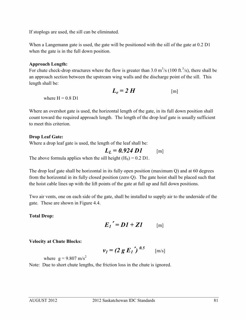
AUGUST 2012 2012 Saskatchewan IDC Standards 81
If stoplogs are used, the sill can be eliminated. When a Langemann gate is used, the gate will be positioned with the sill of the gate at 0.2 D1 when the gate is in the full down position. Approach Length: For chute check-drop structures where the flow is greater than 3.0 m3/s (100 ft.3/s), there shall be an approach section between the upstream wing walls and the discharge point of the sill. This length shall be:
Le = 2 H [m] where H = 0.8 D1
Where an overshot gate is used, the horizontal length of the gate, in its full down position shall count toward the required approach length. The length of the drop leaf gate is usually sufficient to meet this criterion. Drop Leaf Gate: Where a drop leaf gate is used, the length of the leaf shall be:
LL = 0.924 D1 [m] The above formula applies when the sill height (HS) = 0.2 D1. The drop leaf gate shall be horizontal in its fully open position (maximum Q) and at 60 degrees from the horizontal in its fully closed position (zero Q). The gate hoist shall be placed such that the hoist cable lines up with the lift points of the gate at full up and full down positions. Two air vents, one on each side of the gate, shall be installed to supply air to the underside of the gate. These are shown in Figure 4.4. Total Drop:
E1´ = D1 + Z1 [m]
Velocity at Chute Blocks:
v1 = (2 g E1´) 0.5 [m/s] where g = 9.807 m/s2
Note: Due to short chute lengths, the friction loss in the chute is ignored.

AUGUST 2012 2012 Saskatchewan IDC Standards 82
Water Depth at Chute Blocks: d1 = Q / v1 [m]
where Q = canal design flow [m3/s]. Froude Number at Chute Blocks:
F1 = v1 / (g d1) 0.5 Hydraulic Jump Conjugate Depth: d2 = 0.5 d1 [(8 F1
2 + 1) 0.5 – 1] [m] Basin Length: Lb = 3 d2 [m] Check Downstream Canal Depth: For proper hydraulic performance, the conjugate depth (d2) must be less than the downstream normal canal depth (D2). D2 shall be calculated using Manning’s roughness = 0.020 to ensure that adequate tail water exists. If D2 is less than d2, then the basin of the vertical drop structure must be depressed such that the conjugate depth water elevation is equal to or lower than the normal tail water depth calculated with Manning’s roughness = 0.020. This will require recalculation of the chute drop structure dimensions. Chute Block Sizing:
Height = d1 or d2 / 9 or 0.20 m (8”), whichever is greater. Width = d1 or d2 / 9 or 0.20 m (8”), whichever is greater. Spacing = d1 or d2 / 9 or 0.20 m (8”), whichever is greater.
Chute blocks are located at the base (toe) of the chute. Basin Block Sizing:
Height = d1 or d2 / 8 or 0.25 m (10”), whichever is greater. Width = d1 or d2 / 8 or 0.25 m (10”), whichever is greater. Spacing = d1 or d2 / 8 or 0.25 m (10”), whichever is greater.
Basin blocks are located between the chute blocks and the end sill. End Sill Height:
Height = d2 / 10 or 0.20 m (8”), whichever is greater.

AUGUST 2012 2012 Saskatchewan IDC Standards 83
Sub-Slab Drains: Sub-slab drainage shall be provided below the stilling basin as shown in Figure 4.4. A 150 mm (6”) diameter PVC header pipe shall be placed across the structure, below the floor slab, at the chute blocks. The header pipe shall have six rows of 6 mm (1/4 “) diameter inlets spaced at 100 mm (4”) along the length of the header. The header will be connected to 50 mm (2”) diameter PVC drain pipes that exit at every third chute block. The header pipe shall be encased with coarse filter gravel with 300 mm (12”) of gravel thickness between the header and the fine filter gravel. The coarse filter gravel will be encased with fine filter gravel at least 300 mm (12”) thick. The specifications for the coarse and fine filter gravel materials are shown in Section 4.2.18. After the sub-slab drainage system is installed, it shall be covered with foundation concrete. Riprap and Bedding Gravel: Riprap shall be placed downstream of the chute check-drop structure to protect against erosion. Riprap, of the size specified below, shall extend three times the structure width downstream of the structure (bed and side slopes). The riprap and bedding gravel shall be recessed into the sub-grade so that the top of the riprap is even with the bed and side slopes of the canal. All riprap shall be placed on bedding gravel. Size and thickness of the riprap and bedding gravel shall be as follows: Canal Design Riprap Riprap Bedding Flow (Q) Material Thickness Material Thickness 0 to 100 m3/s Size II 500 mm (20”) See Section 4.2.18 300 mm (12”) (0 to 3,500 ft.3/s)

AUGUST 2012 2012 Saskatchewan IDC Standards 84
Figure 4.4: Chute Check-Drop Structure
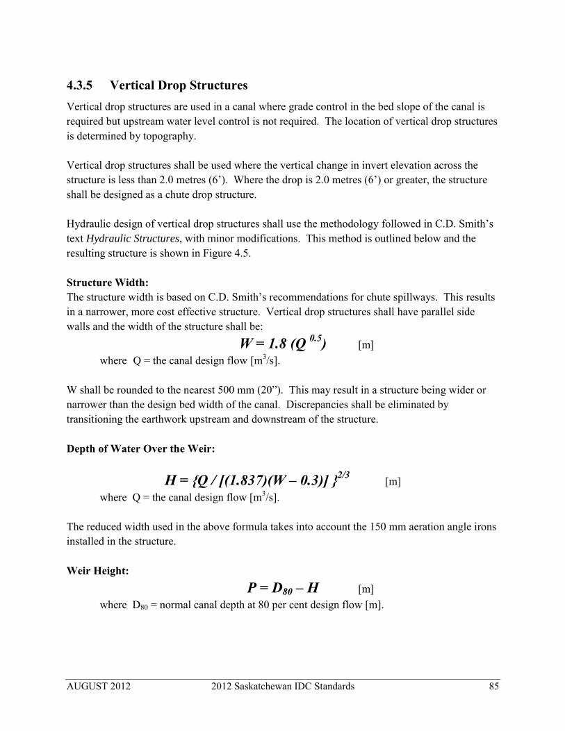
AUGUST 2012 2012 Saskatchewan IDC Standards 85
4.3.5 Vertical Drop Structures Vertical drop structures are used in a canal where grade control in the bed slope of the canal is required but upstream water level control is not required. The location of vertical drop structures is determined by topography. Vertical drop structures shall be used where the vertical change in invert elevation across the structure is less than 2.0 metres (6’). Where the drop is 2.0 metres (6’) or greater, the structure shall be designed as a chute drop structure. Hydraulic design of vertical drop structures shall use the methodology followed in C.D. Smith’s text Hydraulic Structures, with minor modifications. This method is outlined below and the resulting structure is shown in Figure 4.5. Structure Width: The structure width is based on C.D. Smith’s recommendations for chute spillways. This results in a narrower, more cost effective structure. Vertical drop structures shall have parallel side walls and the width of the structure shall be:
W = 1.8 (Q 0.5) [m] where Q = the canal design flow [m3/s].
W shall be rounded to the nearest 500 mm (20”). This may result in a structure being wider or narrower than the design bed width of the canal. Discrepancies shall be eliminated by transitioning the earthwork upstream and downstream of the structure. Depth of Water Over the Weir:
H = {Q / [(1.837)(W – 0.3)] }2/3 [m]
where Q = the canal design flow [m3/s]. The reduced width used in the above formula takes into account the 150 mm aeration angle irons installed in the structure. Weir Height: P = D80 – H [m]
where D80 = normal canal depth at 80 per cent design flow [m].

AUGUST 2012 2012 Saskatchewan IDC Standards 86
Total Drop Height:
E1´ = D1 + Z1 [m] where D1 = the upstream normal canal depth at design flow [m] Z1 = upstream bed elevation – downstream bed elevation [m]
Note: Due to low canal velocities, the velocity head is ignored. Net Drop: The net drop (E1) is calculated using the following three formulae:
x = H / (P + Z1) [m]
y = 0.69896 x3 - 2.1207 x2 + 2.0739 x + 0.27664
E1 = y E1´ Velocity at End of Nappe:
v1 = (2 g E1´) 0.5 [m] where g = 9.807 m/s2
Water Depth at End of Nappe: d1 = Q / v1 [m] Froude Number at End of Nappe:
F1 = v1 / (g d1) 0.5 Hydraulic Jump Conjugate Depth: d2 = 0.5 d1 [(8 F1
2 + 1) 0.5 – 1] [m] Approach Length: For vertical drop structures where the flow is greater than 3.0 m3/s (100 ft.3/s), there shall be an approach section between the upstream wing walls and the discharge point of the sill. This length shall be:
Le = 2 H [m]
AUGUST 2012 2012 Saskatchewan IDC Standards 87
Nappe Travel Distance: E1 [m] (As calculated previously) Basin Length: Lb = 3 d2 [m] Check Downstream Canal Depth: For proper hydraulic performance, the conjugate depth (d2) must be less than the downstream normal canal depth (D2). D2 shall be calculated using Manning’s roughness = 0.020 to ensure that adequate tail water exists. If D2 is less than d2, then the basin of the vertical drop structure must be depressed such that the conjugate depth water elevation is equal to or lower than the normal tail water depth calculated with Manning’s roughness = 0.020. This will require recalculation of the vertical drop structure dimensions. Basin Block Sizing:
Height = d1 or d2 / 8 or 0.25 m (10”), whichever is greater. Width = d1 or d2 / 8 or 0.25 m (10”), whichever is greater. Spacing = d1 or d2 / 8 or 0.25 m (10”), whichever is greater.
End Sill Height: Height = d2 / 10 or 0.20 m (8”), whichever is greater.
Corners: The upstream headwall shall transition into the structure sidewalls with:
A curved wall with a minimum radius of 300 mm (12”), or A bevelled, chamfered edge of at least 300 mm (12”).
Riprap and Bedding Gravel: Riprap shall be placed downstream of the vertical drop structure to protect against erosion. Riprap shall extend three times the structure width downstream of the structure (bed and side slopes). The riprap and bedding gravel shall be recessed into the sub-grade so that the top of the riprap is even with the bed and side slopes of the canal. All riprap shall be placed on bedding gravel. Size and thickness of the riprap and bedding gravel shall be as follows:

AUGUST 2012 2012 Saskatchewan IDC Standards 88
Canal DesignRiprap Riprap Bedding Flow (Q) Material Thickness Material Thickness 0 to 15 m3/s Size I 300 mm (12”) See Section 4.2.18 150 mm (6”) (0 to 530 ft.3/s) 15 to 100 m3/s Size II 500 mm (12”) See Section 4.2.18 300 mm (12”) (530 to 3,500 ft.3/s)

AUGUST 2012 2012 Saskatchewan IDC Standards 89
Figure 4.5: Vertical Drop Structure

AUGUST 2012 2012 Saskatchewan IDC Standards 90
4.3.6 Chute Drop Structures Chute drop structures are used in a canal where grade control in the bed slope of the canal is required but upstream water level control is not required. The location of chute drop structures is determined by topography. Chute drop structures shall be used where the vertical change in hydraulic grade line across the structure is 2.0 metres (6’) or greater. Where the drop is less than 2.0 metres (6’), the structure shall be designed as a vertical drop structure. Hydraulic design of chute drop structures shall use the methodology identified by C.D. Smith’s text Hydraulic Structures. This method is outlined below and the resulting structure is shown in Figure 4.6. Structure Width: The structure width is based on C.D. Smith’s recommendations for chute spillways. This results in a narrower, more cost effective structure. Chute drop structures shall have parallel side walls and the width of the structure shall be:
W = 1.8 (Q 0.5) [m] where Q = the canal design flow [m3/s].
W shall be rounded to the nearest 500 mm (20”). This may result in a structure being wider or narrower than the design bed width of the canal. Discrepancies shall be eliminated by transitioning the earthwork upstream and downstream of the structure. Depth of Water Over the Weir:
H = {Q / [(1.837)(W – 0.3)] }2/3 [m]
where Q = the canal design flow [m3/s].
Weir Height: P = D80 – H [m]
where D80 = normal canal depth at 80 per cent design flow [m]

AUGUST 2012 2012 Saskatchewan IDC Standards 91
Total Drop Height:
E1´ = D1 + Z1 [m] where D1 = the upstream normal canal depth at design flow [m] Z1 = upstream bed elevation – downstream bed elevation [m] Note: Due to the low canal velocities, the velocity head is ignored.
Velocity at Chute Blocks:
v1 = [2 g E1´] 0.5 [m] where g = 9.807 m/s2 Note: Due to the short chute lengths, the friction loss in the chute is ignored.
Water Depth at Chute Blocks: d1 = Q / v1 [m] Froude Number at Chute Blocks:
F1 = v1 / (g d1) 0.5 Hydraulic Jump Conjugate Depth: d2 = 0.5 d1 [(8 F1
2 + 1)] 0.5 – 1] [m] Approach Length: For chute drop structures where the flow is greater than 3.0 m3/s (100 ft.3/s), there shall be an approach section between the upstream wing walls and the discharge point of the sill. This length shall be:
Le = 2 H [m] Basin Length: Lb = 3 d2 [m] Check Downstream Canal Depth: For proper hydraulic performance, the conjugate depth (d2) must be less than the downstream normal canal depth (D2). D2 shall be calculated using Manning’s roughness = 0.020 to ensure that adequate tail water exists. Also, d2 must be designed to be inside the chute drop structure or there will be instability in the hydraulic jump across the outside to the structure. This instability can cause severe canal bank erosion when the hydraulic jump is swept downstream. If D2 is less than d2, then the basin of the chute drop structure must be depressed such that the conjugate depth water elevation is equal to or lower than the normal tail water depth calculated
AUGUST 2012 2012 Saskatchewan IDC Standards 92
with Manning’s roughness = 0.020. This will require recalculation of the chute drop structure dimensions. Chute Block Sizing:
Height = d1 or d2 / 9 or 0.20 m (8”), whichever is greater. Width = d1 or d2 / 9 or 0.20 m (8”), whichever is greater. Spacing = d1 or d2 / 9 or 0.20 m (8”), whichever is greater.
Chute blocks are located at the base (toe) of the chute. Basin Block Sizing:
Height = d1 or d2 / 8 or 0.25 m (10”), whichever is greater. Width = d1 or d2 / 8 or 0.25 m (10”), whichever is greater. Spacing = d1 or d2 / 8 or 0.25 m (10”), whichever is greater.
Basin blocks are located between the chute blocks and the end sill. End Sill Height:
Height = d2 / 10 or 0.20 m (8”), whichever is greater. Corners: The upstream headwall shall transition into the structure sidewalls with:
A curved wall with a minimum radius of 300 mm (12”), or A bevelled, chamfered edge of at least 300 mm (12”).
Sub-Slab Drains: Sub-slab drainage shall be provided below the stilling basin as shown in Figure 4.6. A 150 mm (6”) diameter PVC header pipe shall be placed across the structure, below the floor slab, at the chute blocks. The header pipe shall have six rows of 6 mm (1/4”) diameter inlets spaced at 100 mm (4”) along the length of the header. The header shall be connected to 50 mm (2”) diameter PVC drain pipes that exit at every third chute block. The header pipe shall be encased in a coarse filter gravel with 300 mm (12”) of gravel thickness between the header and the fine filter. The coarse filter gravel shall be encased in a fine filter gravel at least 300 mm (12”) thick. The specifications for the coarse and fine filter gravel material are shown in Section 4.2.18. After the sub-slab drainage system is installed, it shall be covered with foundation concrete. Riprap and Bedding Gravel: Riprap shall be placed downstream of the chute drop structure to protect against erosion. Riprap shall extend a minimum of three times the structure width downstream of the structure (bed and side slopes). The riprap and bedding gravel shall be recessed into the sub-grade so that the top of the riprap is even with the bed and side slopes of the canal. All riprap shall be placed on bedding gravel. Size and thickness of the riprap and bedding gravel shall be as follows:

AUGUST 2012 2012 Saskatchewan IDC Standards 93
Canal Design Riprap Riprap Bedding Flow (Q) Material Thickness Material Thickness
0 to 15 m3/s Size I 300 mm (12”) See Section 4.2.18 150 mm (6”) (0 to 530 ft.3/s) 15 to 100 m3/s Size II 500 mm (20”) See Section 4.2.18 300 mm (12”) (530 to 3,500 ft.3/s)

AUGUST 2012 2012 Saskatchewan IDC Standards 94
Figure 4.6: Chute Drop Structure

AUGUST 2012 2012 Saskatchewan IDC Standards 95
4.4 TURNOUTS AND WASTE WAYS Turnout structures divert water from the supply canal and discharge into either a farm delivery system, pipeline, lateral canal or waste way and are sized accordingly. Types of turnout include gated chutes, gated turnouts, pipeline inlets or wet wells. Where there exists the potential for washout or erosion of the inlet, turnouts shall have adequately sized concrete headwalls to provide the necessary seepage cut-off. The use of siphons are not recommended for any turnouts.
4.4.1 Gated Turnouts Gated turnouts are popular and used for a wide range of flows. These turnouts shall incorporate:
Watertight gates with head rating equal to or higher than the canal design depth; and Submerged outlets or impact baffles, stilling basins or additional riprap in order to
dissipate excess energy.
4.4.1.1 Large Lateral Turnouts and Head Gates
These turnouts provide a regulated flow out of the canal to another canal where the supply canal bed and the receiving canal bed are at a similar elevation. This turnout is similar to a check structure with a stilling basin to dissipate excess energy and one or more undershot gates for flow control. When this type of turnout is used, it must have a bridge deck to allow vehicles to cross the structure and be aligned with the canal bank. This is required for access along the canal. Overshot gates should not be used on lateral turnouts except when an overshot gate is used with flow control software. However, the canal downstream of the turnout must be capable of conveying the surge flow in the event of gate failure.
4.4.1.2 Pipe Turnouts
Pipe turnouts provide a flow out of a canal through a short section of pipe to another canal. Pipe turnouts shall incorporate a horizontal pipe, such as PVC pipe, concrete pipe or CSP with a wall thickness not less than 2.0 mm (0.08”), with watertight couplers. The use of PVC is recommended due to its watertight joints, non-corrosive characteristics and ability to resist failure due to settlement at the headwall.

AUGUST 2012 2012 Saskatchewan IDC Standards 96
Where the supply canal design flow rate exceeds 3.0 m3/s (100 ft.3/s) these structures shall also incorporate:
A full headwall and cut-off wall along the full width of the structure at the gate; and Sloped sidewalls and floors upstream of the headwall for stability.
4.4.1.3 Gated Chute Turnouts
These turnouts provide a regulated flow out of the canal where the supply canal bed is significantly higher than the receiving canal bed. This turnout is similar to a chute check-drop structure with a stilling basin to dissipate excess energy and one or more undershot gates for flow control. This structure shall be designed as indicated in Section 4.3.4: Chute Check-Drop. When this type of turnout is used, it must have a bridge deck to allow vehicle to cross the structure and be aligned with the canal bank. The bridge deck is required for access along the canal. Overshot gates should not be used on the gated chute turnout except when an overshot gate with flow control software is used. However, the canal downstream of the turnout must be capable of conveying the surge flow in the event of gate failure.
4.4.2 Pipeline Inlet Structures This type of turnout is similar to the pipe turnout. The turnout invert could be below the supply canal bed, in which case a drop inlet or a Z-drop would be required. A headwall and cut-off wall with sloping side wall is required at the gate if the design flow rate in the supply canal exceeds 3.0 m3/s (100 ft.3/s). The floor may either slope downwards or drop vertically to the pipe invert. This type of turnout shall also incorporate:
Pipe as approved for pipelines (See Chapter 3); Watertight slide gates with head rating equal to or higher than the design depth; and Trash rack for safety and exclusion of trash.
4.4.3 Wet-Well Pump Turnouts These turnouts are often sited beside a canal as pump intakes and water level monitoring wells. All wet-well pump turnouts should be steel or adequately reinforced concrete. A ladder shall be provided on all wet-wells for maintenance, safety and security purposes. Adequate covers (manhole covers) should be placed on wet-wells. These covers may be solid, perforated metal, or made of bars so that people, livestock or wildlife cannot accidently enter the manhole. Where the well is used as a pump intake, adequate openings shall be made in the cover so that the pump can be operated without the cover being removed and adequate trash rack guides provided at the inlet. If there is a chance of the wet-well being damaged by machinery, the area around it should be fenced off.

AUGUST 2012 2012 Saskatchewan IDC Standards 97
4.4.3.1 High Side Turnouts
This turnout is used as a pump intake on the upslope side of canals or in cut sections where the natural ground is above the FSL of the canal. This turnout is a horizontal pipe installed through the bank and connected to a 1.2 metres (48”) minimum diameter vertical pipe to form a well. A gate may be provided on the horizontal pipe at the well for control. The top of the vertical section shall be above the FSL of the canal plus calculated freeboard (Section 2.1.4) or shall be a minimum of 300 mm (12”) above ground level, whichever is higher.
4.4.3.2 Low Side Turnouts
Where the ground level around the wet well is below the FSL of the canal, more substantial protection is required to prevent pipe failure (See Section 4.4.1.2). The top of the vertical section shall be above the FSL of the canal plus calculated freeboard (Section 2.1.4) and shall be a minimum of 300 mm (12”) above ground level, whichever is higher. In cases where the wet well is a significant distance from the canal, a higher vertical height may be required to prevent over-topping on pump shutdown due to the effects of hydraulic transients.
4.4.4 Major Waste Ways Typically, these are large turnouts that divert excess canal and storm flows out of the canal system. Excess flows may also be caused by system shutdowns on pipelines upstream of the waste way. Waste ways typically require control gates and the waste ways can range from having minimal to significant elevation drop. Waste ways with significant drop require appropriately designed check structures, vertical check-drop structures or chute check-drop structures that incorporate fixed crest heights or overshot gates.
4.5 PRECAST CONCRETE STRUCTURES For small canals and low flow rates, precast concrete structures can be a cost-effective alternative to cast-in-place concrete structures. The hydraulic design considerations are similar to those for cast-in-place structures. In cases where precast structures are used, the P. Eng. or P.L. (Eng.) responsible for the IRP project is responsible for selecting suitable precast components and appropriately incorporating them into the system. All precast concrete components shall be manufactured using sulphate-resistant concrete.
AUGUST 2012 2012 Saskatchewan IDC Standards 98
CHAPTER 5: SEEPAGE CONTROL Studies have shown that the amount of water lost to seepage from canals in the irrigation districts is small, but even minor seepage can be damaging to adjacent land and structures. The primary purpose of seepage control is to prevent seepage damage, rather than to conserve water. However, there are cases (e.g. gravel seams) where the volume of water lost due to seepage can be significant. Before incorporating any seepage control method as part of an irrigation engineering project, it must be determined whether the water logging or salinization of the land adjacent to the irrigation works is a result of seepage from the works or a result of natural ground water effects, or a combination of both. In some cases, seepage sites observed near canals and drains may be the result of permeable soil deposits under canals conveying water from upland and distant sources. An effective solution to the problem is not possible unless the source of the problem is known. For example, if the cause of the problem is determined to be canal seepage and a preventative measure is installed (e.g. plastic lining), the result could be the lifting of the liner if natural groundwater causes positive lift pressure under the liner. In these cases, liners with one-way valves may be required (to let groundwater enter the canal when it is present). Another, more effective solution in these cases, may be to install a cut-off curtain and sub-surface interceptor tile drain adjacent to the canal. However, if such a solution is adopted, then the curtain and interceptor must prevent groundwater flows through underlying permeable soil strata, if such exists. There may also be cases where the seepage from the canal, although present, is not causing damage to the adjacent land. The seepage water may actually increase pasture hay or crop production on the adjacent land. Water table control and sub-surface irrigation use the water table to provide root zone moisture. In other cases, canal seepage may be creating wildlife habitat in an area where the maintenance of that habitat is the best use of the land in question and elimination of that seepage would not be desirable. The selection of the appropriate seepage control measure depends upon relative costs and the groundwater and hydrogeology near the canal. Lined canals and pipelines are often the most effective method of seepage control. Chapters 2 and 3 present these measures. Where seepage control measures require an outlet into a natural channel, then the Saskatchewan Watershed Authority (SWA) must pre-approve and authorize the construction. Where seepage discharges into irrigation district drains then, in additionally to SWA, the irrigation district must be pre-approve and authorize the construction. The effect of the drainage water on algae growth, introduction of undesired pathogens or chemicals into the downstream water supply, impact on

AUGUST 2012 2012 Saskatchewan IDC Standards 99
near-by roads and structures, and increased flows will be some of the factors considered when evaluating the seepage control project.
5.1 CUT-OFF CURTAINS In order to be effective, a cut-off curtain shall be anchored into an impervious layer within the soil profile. The cut-off curtain has these common features:
Material: The cut-off curtain shall be a plastic membrane meeting the specifications given in Sections 2.3.5 or 2.3.6.
Temperature: Installation shall not occur in temperatures where the material could be
damaged due to handling or impact when the fill material is applied to the surface of the liner. Generally, polyethylene (PE) can be installed in colder temperatures than polyvinyl chloride (PVC), but in all cases, the manufacturer’s recommendations shall be followed.
Field Joints: For PVC, transverse field joints shall be lapped a minimum of 1.5 metres
(5’), or lapped 300 mm (12”) if adhesive is used or if the joint is heat-sealed. For PE, the material should be lapped a minimum of 1.5 metres (5’) or double-folded.
5.1.1 Cut-Off Curtains – Inside Canals This impervious curtain usually begins at the same slope as the bank’s inside side slope, with the bottom end being steeper and keyed into the impervious material below. The top shall be keyed into a horizontal ledge similar to canal lining. The top shall be at least 150 mm (6”) higher than the FSL of the canal.
5.1.2 Cut-Off Curtains – Outside Canals When used alone, exterior cut-off curtains shall be installed parallel to the canal bank by open trenching and backfill. Exterior cut-off curtains may be installed vertically or at the same slope as the bank’s outside side slope with the bottom end installed in an impervious material deep enough to intercept all the seepage. Construction of an exterior cut-off curtain can be completed independently of canal construction. Cut-off curtains are used where the canal cross section is constructed in relatively permeable soil material. This permeable material must be underlain by material of low permeability at relatively shallow depth, usually 4.0 metres (13’) or less. The base of the curtain shall be properly anchored (keyed) into the low permeability material for the curtain to be effective.

AUGUST 2012 2012 Saskatchewan IDC Standards 100
5.2 CLAY CUT-OFF (CORE TRENCH) CURTAIN A clay cut-off barrier is excavated and constructed as part of the canal bank. Clay cut-offs may be cost-effective when the impervious zone is less than 2.0 metres (6.5’) below the canal bed. This method is used to key clay material into the underlying impervious zone. The clay cut-off shall extend vertically to 300 mm (12”) above FSL and be embedded 500 mm (20”) into the impervious zone below the trench. The clay cut-off should have a horizontal width of not less than 300 mm (12”). Clay cut-off trenches may be effective but usually are not recommended due to problems found in sustaining an open trench in the wet ground conditions often found in areas affected by seepage.
5.3 INTERCEPTOR DRAINS
5.3.1 Open Interceptor Drains (Ditches) Open interceptor drains may be effective when the ditch sufficiently deep and when the ditch crosses the direction of ground water flow. Generally, open interceptor ditches are not recommended due to the land and maintenance requirements.
5.3.2 Pipe Interceptor Drains Pipe interceptor drains are typically constructed of perforated corrugated PE or PVC pipe (i.e. drain tile) and surrounded by a gravel envelope. The diameter of the pipe shall be sufficient to carry the required flow at the gradient at which the pipe is installed. Diameters of 150 to 200 mm (6 to 8”) are typical. If designed and installed correctly, the interceptor drain lowers the water table to the depth of the drain. Interceptor drains are used when soils are relatively permeable and the seepage gradient is relatively steep. A cut-off curtain placed downslope of the drain or a gravel chimney placed directly above the drain shall be incorporated to prevent seepage water from flowing past the drain.
5.3.2.1 Drain Depth
An interceptor drain is installed lower than the bed of the canal and is most effective when it lies on a low-permeability soil. Where an interceptor drain is placed above low-permeability soils on sloping land, additional drains are required downslope to intercept seepage water that moves under and past the drain.

AUGUST 2012 2012 Saskatchewan IDC Standards 101
5.3.2.2 Drain Gradient
The minimum allowable slope for interceptor drains shall be as shown in Table 5.1. TABLE 5.1: Drain Gradient
Drain Diameter (mm) Minimum Gradient 75 (3”) 0.0015
100 (4”) 0.0010 150 (6”) 0.0010 200 (8”) 0.0008 250 (10”) 0.0008 300 (12”) 0.0006
5.3.2.3 Manholes
The installation of inspection and maintenance manholes is recommended every 400 metres (1,300’) along interceptor drains.
5.3.2.4 Outlets
Plastic outlet pipes into open channels shall be protected by the use of corrugated steel pipe (CSP) equipped with a rodent guard. The maximum spacing between slots on the rodent guard shall be 20 mm (3/4”). The CSP shall be a minimum length of 3.0 metres (10’) and at least two-thirds shall be embedded into the bank. The invert of free-draining sub-surface drainage outlets should be not less than 300 mm (12”) above the ditch bottom or 300 mm (12”) above the standing water level in the drain during the irrigation season. All side slopes and slopes below drain outlets should be adequately protected from erosion by appropriate rip rap or other erosion protection material.
Outlets into manholes, observation wells and pumped outlets shall be protected where they enter the manhole to prevent damage from differential settlement. For observation wells and other manholes, the invert elevations of pipes entering the manhole should be above the invert elevation of pipes exiting the manhole.
Where sub-surface drainage discharges into a natural channel or other works not owned by the irrigation district, then SWA must be contacted to determine what approvals are needed prior to beginning construction.
5.4 GRID SUB-SURFACE DRAINAGE In situations where other methods of seepage control are not effective, a grid sub-surface drainage system may be the most cost-effective method to dispose of the seepage leaving the irrigation works. Sub-surface drainage removes water from the soil profile. Grid drainage systems also have the advantage of disposing of excess water from other sources, in addition to the seepage from irrigation works.

AUGUST 2012 2012 Saskatchewan IDC Standards 102
5.4.1 Grid Sub-Surface Drainage Design Grid drainage is most appropriately used when other sources of excess water, in addition to canal seepage, are contributing to seepage-affected land. Other sources of excess water may be local or regional groundwater discharge or surface ponds.
5.4.1.1 Drain Depth
The recommended depth for grid drainage systems is from 1.2 to 2.0 metres (4’ to 6’). The minimum cover over grid drainage tubing is 1.0 metre (3.3’).
5.4.1.2 Drain Gradient
The minimum allowable drain slope shall be as shown in Table 5.1.
5.4.1.3 Outlets
Plastic outlet pipes into open channels shall be protected by the use of corrugated steel pipe (CSP) equipped with a rodent guard. The maximum spacing between slots on the rodent guard shall be 20 mm (3/4”). The CSP shall be a minimum length of 3.0 metres (10’) and at least two thirds shall be embedded into the bank. The invert of free-draining sub-surface drainage outlets should be not less than 300 mm (12”) above the ditch bottom or 300 mm (12 “) above the standing water level in the drain during the irrigation season. All side slopes and slopes below drain outlets should be adequately protected from erosion by appropriate rip rap or other erosion- protection material
Outlets into manholes, observation wells and pumped outlets shall be protected where they enter the manhole to prevent damage due to differential settlement. For observation wells, and other manholes, the invert elevation of pipes entering the manhole should be above the invert elevation of pipes exiting the manhole.
Where sub-surface drainage systems incorporate an outlet into a natural channel or other works not owned by the irrigator, then SWA shall be contacted to determine what approvals are needed prior to commencing construction.
5.4.1.4 Manholes and Air Inlets
Manholes are not normally required with grid drainage systems, except for pumped outlets and observation wells. Consideration should be given to providing an air inlet at the upper end of a grid drain.

AUGUST 2012 2012 Saskatchewan IDC Standards 103
5.4.2 Grid Drain Construction
5.4.2.1 Trenching
A smooth trench bottom shall be constructed for drain pipe installation in order to provide uniform support under the pipe. The size of the trench shall conform closely to the diameter of the pipe. Construction using excavation equipment other than sub-surface drainage ploughs or trenchers (e.g. backhoe) should be avoided because adequate grade control, pipe bedding, and backfill are difficult to maintain with other types of equipment. Whatever type of equipment is used for excavation and installation of the drain lines, automatic grade control (e.g. laser, survey-grade GPS) shall be used. Construction shall not damage existing utilities and services such as pipeline, fibre optic cables, gas lines, buried telephone and power lines, etc. The installation company shall follow all applicable requirements described in the most recent edition of The Saskatchewan Occupational
Health and Safety Act and the Occupational Health and Safety Regulations.
5.5 DRAINAGE MATERIALS All materials used in drain construction shall conform to the appropriate standards. Whether PVC or corrugated PE, all pipe and tubing shall meet the applicable standards. Filter fabric is discussed in Section 5.5.5.
5.5.1 Corrugated PE Drain Pipe This pipe shall meet the standards outlined in CGSB 41-GP-29 Ma, Corrugated Plastic Drain
Tubing. The pipe shall also conform to the standard for elongation in ASTM F405-77a, Corrugated Polyethylene Tubing and Fittings
5.5.2 Perforated PVC Pipe This pipe shall meet the standards:
Standard Duty (DR 35) CSA B182.1 (100 mm to 150 mm) (4” to 6”) Plastic Drain and Sewer Pipe Fittings CSA B182.2 (200 mm to 675 mm) (8” to 27”) ASTM D-3034 (200 mm to 375 mm) (8” to 15”) ASTM F-679 (450 mm to 675 mm) (18” to 27”)

AUGUST 2012 2012 Saskatchewan IDC Standards 104
Heavy Duty (DR 26) CSA B 137-3 (50 mm to 600 mm) (2” to 24”) Rigid Polyvinyl Chloride (PVC) Pipe for
Pressure Applications ASTM D-2241 (50 mm to 600 mm) (2” to 24”)
5.5.3 Gravel Chimney Material used to construct a gravel chimney shall conform to the gradation shown in Table 5.2:
TABLE 5.2: Chimney and Bedding Material Gradation Sieve Size Per Cent (%) Passing 25 mm (1”) 100
10 mm (3/8”) 45 to 85 5 mm (1/4”) 15 to 40
2.5 mm (0.1”) < 10 1.0 mm (0.08”) < 4
5.5.4 Gravel Bedding Granular material may be used as bedding to provide a firm base to support the pipe or tubing where the trench bottom is unstable. In these cases, the material shall meet the gradation listed in Table 5.2.
5.5.5 Filter Socks Filter fabric for drain tubing shall be hydrophilic and have sufficient permeability to allow free flow into the drain. Based on the drain pipe selection and particle size distribution of the material being drained, an appropriate filter sock, with or without a gravel envelope, may be specified for the drainage pipe. The main purpose of a gravel (or other material) envelope or chimney drain is to improve the flow into the drain. The main purpose of the filter sock is to prevent material that might clog the drain from entering into the drain pipe. Generally, filter socks shall be used in sandy or gravely soils to prevent sand or silt from entering and plugging the drain. Pipe installed in stratified clay soils with interspersed sand layers should be covered with a filter sock; however un-stratified soils with a clay content exceeding 40 per cent do not need a filter sock. Soils with a plasticity index of at least 12 have shown no tendency to leave silt deposits. Drain pipe without a filter sock is likely to clog when it is installed in any soil having a cumulative particle size distribution that lies completely, or largely, in the shaded area shown in Figure 5.1.

AUGUST 2012 2012 Saskatchewan IDC Standards 105
For further details on the need and selection of drain envelope or sock materials, refer to the 2005 FAO Irrigation and Drainage Paper #60 (Rev. 1) Materials for Sub-surface Land Drainage
Systems by Stuyt, Dierickx and Beltran. This publication presents guidelines for envelopes and appropriate materials (i.e. pipes and envelopes) for sub-surface drainage systems. It also contains guidelines for installation and maintenance of drainage materials. Figure 5.1 is a copy of Figure 42 as shown in that publication.
Figure 5.1: Soil Particle Sizes – Drain Clogging Potential Figure 42 from FAO Irrigation and Drainage Paper #60 (Rev. 1)
5.5.6 Manholes CSP, precast concrete and corrugated PE are all suitable manhole materials. Concrete and PE have the advantage of being less subject to corrosion. The pipeline entrance into the manhole should be sealed very well in order prevent soil entering the sump.

AUGUST 2012 2012 Saskatchewan IDC Standards 106
CHAPTER 6: SURFACE DRAINAGE WORKS An agricultural drainage system, whether open ditches or closed pipes, shall be large enough to remove and dispose of excess water from agricultural lands quickly enough to prevent significant crop damage. Overall, a drainage system also needs to provide flood control from spring snowmelt, runoff, and precipitation events. Surface drainage works remove water from the ground surface. Drainage improvements need to consider the irrigation certification requirements, irrigation land and irrigation district infrastructure. Typically, surface drains are open channels or ditches that are constructed to convey:
Spill water from canals and laterals,
Runoff from irrigated parcels, and/or
Slough drainage projects on irrigated areas.
The surface drainage of an area should be given a priority over sub-surface drainage. It is recommended that the opportunities for surface drainage should be fully assessed before undertaking sub-surface drainage work. In some cases open pipelines are constructed to serve as drainage works to convey spill water, runoff and/or return flow. Drainage designs can become complicated so the assistance of a professional designer, knowledgeable in drainage and irrigation, is recommended.
6.1 REQUIRED CAPACITIES The capacity requirement depends upon the amount of water to be collected and conveyed. Natural surface runoff may also have to be accommodated in some cases. Typically the summer runoff peak flows are higher than the spring runoff peak flows but the spring runoff peak volumes are higher than summer runoff volumes.
6.2 OPEN CHANNEL DRAINAGE DESIGN The design of drainage channels shall follow the same criteria set out in Section 2.1 for open channels, subject to the exceptions:
Gravel armour is normally not required, but the potential for erosion must be kept to a minimum.
Liners are normally not required. Side-slopes as steep as 2:1 (horizontal-to-vertical) are acceptable. Driving banks are optional, but should be provided where regular inspection and on-
going maintenance are anticipated.
AUGUST 2012 2012 Saskatchewan IDC Standards 107
6.3 CULVERT CROSSINGS Culverts or road crossings installed as part of the irrigation drainage system shall be sized to handle the design flow rate for the expected irrigation flow. Where the system is designed to handle irrigation drainage and natural drainage as well, sizing of the culvert crossings is more difficult. If they are overly large, excess flow is conveyed downstream, possibly causing damage to the downstream landowners.
6.4 OUTLETS AND DISCHARGE The disposal of surface runoff into irrigation district works must be considered in the channel design process. Where surface drainage systems discharge into irrigation district works or a natural channel, then the irrigation district and SWA must be contacted to determine what approvals are needed prior to commencing construction.

AUGUST 2012 2012 Saskatchewan IDC Standards 108
Appendix A: DEFINITIONS allowable working pressure is the maximum working pressure for a PVC pipeline provided for
PVC Transmission Pipelines based on AWWA C905. armour or armouring refers to the coarse granular lining used on the side slopes of earth canals
for erosion protection. basin blocks are concrete blocks used for energy dissipation in hydraulic structures and located
in the stilling basin of the structure, between the chute blocks and the end sill. bed width or bottom width is the width of the bottom of the cross section of the open channel
(canal). bedding backfill refers to the material and placement of fill material below the initial backfill
and invert of the pipe cross section perimeter. Special granular bedding material, even filter cloth, may be needed to establish an uniform support for the pipe below the pipe grade.
berm is a horizontal break either in the inside or outside bank side slope of a channel. buried membrane-lined canal is an open channel earthen canal with a membrane liner covered
by either earth or gravel, or earth overlaid with gravel. canal is an open channel that conveys irrigation water to serve other canals (laterals) or to the
farm. Canals, laterals and sub-laterals are all included in the definition of a canal. chute blocks are concrete blocks used for energy dissipation in hydraulic structures and are
located at the base (toe) of the chute. closed pipeline is a pipeline that flows full throughout its entire length. The flow is maintained
by gravity or pumped pressure. compaction is the process where a sufficient amount of energy is applied to a soil mass to reduce
the soil volume and achieve a specific soil density. concrete-lined canal is an open channel earthen canal where the wetted surface and freeboard is
constructed of a layer of concrete.

AUGUST 2012 2012 Saskatchewan IDC Standards 109
core trench is compacted clay material installed under the canal bank as part of a seepage control system.
corrosion is the deterioration of a material, usually a metal, that results from a reaction with its
environment. cover is the depth of backfill over the top of the pipe. crown is the top or highest point of the internal surface of the transverse cross section of a pipe. culvert is a conduit for conveying surface water under an embankment, which may provide a
crossing for a highway, county road or railway, designed to flow according to open channel flow equations.
culvert inlet control is culvert flow that is controlled at the culvert entrance by the depth of
headwater and the entrance geometry of the culvert, including the barrel shape, cross sectional area and the inlet edge.
culvert outlet control is culvert flow that occurs when the culvert barrel is not capable of
conveying as much flow as the inlet opening will accept. cut-off curtain is a synthetic membrane installed on one or both sides of a canal to prevent
seepage water from bridging above a sub-surface drain. drainage is the interception and removal of ground water or surface water by artificial or natural
means. drainage coefficient is the rate of water removal by a designed drainage system. This may be
thought of as the depth of water to be removed from the surface of a unit of area per 24-hour period.
deep interceptor drain is a buried pipe drain installed 2.0 to 4.0 metres (6’ to 12’) below ground
and parallel to a canal for the purpose of intercepting seepage. depth or flow depth is the vertical distance from the bed (invert) of the flow area to the surface
of the water in an open channel or open pipeline. design operating pressure is the highest pressure that will develop in a pipeline. The pressure
includes static and dynamic pressures and water hammer. This operating pressure should not exceed the operating pressure of the pipe.

AUGUST 2012 2012 Saskatchewan IDC Standards 110
dimension ratio (DR) is the ratio of the outside pipe diameter to wall thickness for thermoplastic
pipes. Also known as Standard Dimension Ratio (SDR). distribution pipeline is piping that acts as a header for distributing water through numerous and
frequent lateral connections, as in residential developments with frequent service connections.
drain envelope consists of gravel placed around, or around and above chimney drains, or
drainage tile to improve the flow into the drain. earthen canal is an open channel, usually of trapezoidal cross section, excavated and shaped to a
specific cross section in natural earth or fill. exterior cut-off curtain is a synthetic material installed on the outside bank or toe of the canal to
prevent or reduce seepage. filter sock is a woven fabric mesh installed over and around the drainage pipe to prevent
sediment from entering the drain. final backfill refers to the material and placement of fill material above the initial backfill zones
and below the ground surface. Consideration needs to be given to mounding the backfill and soil settlement at the ground surface.
flood frequency is the average time interval in years in which a flow of a given magnitude from
a specific area, taken from an infinite series of flood events for this area, will recur. freeboard is the vertical distance from FSL (or water level checked depth) to the top of the bank
of a canal. full supply (service) level (FSL) is the design water surface elevation. It is the greater of the
normal design flow depth or the checked water depth. grid drainage is a series of parallel, regularly spaced corrugated polyethylene tube drains
throughout the area affected by seepage. Drain depths vary from 1.0 to 1.8 m. gravel chimney is a vertical trench constructed directly above a sub-surface drain and filled with
gravel to improve flow into the drain.

AUGUST 2012 2012 Saskatchewan IDC Standards 111
gravity irrigation is surface irrigation that uses uniform, steady state, open channel flow to spread water over the field surface, using the field’s topography and soil’s infiltration and moisture retention capacity to provide water to the crops. Flow rate, duration of flow and drainage from the field are also important considerations.
haunches or hauching refers to outside areas of a buried pipe between the spring line and the
bottom of the pipe. The backfill of the haunches needs adequate and balanced compaction to prevent pipe displacement or deflection.
initial backfill refers to the material and placement of fill material extending from the spring line
of a buried pipe to at least a 300 mm (12”) height above the crown of a buried pipe. interior cut-off curtain is a sub-surface drainage system installed on the inside bank of a canal. interceptor drain is a ditch or closed drain tile located across the direction of ground water flow
and installed to intercept sub-surface flow. In terms of canals, it is a type of drainage system used to intercept seepage from a canal and prevent it from moving downslope.
invert is the bottom or lowest point of the internal surface of the transverse cross section of a
pipe. lined canal is an earthen canal lined to reduce or eliminate seepage. It includes earth, buried-
membrane-lined and clay-lined canals. Armouring of the bed and/or banks of a canal is not considered lining.
net positive suction head [available (NPSH A) or required (NPSHR )] is the pressure head on
the suction side of the pump that causes liquid to flow through the intake piping and into the eye of the pump impeller. (NPSHA) is the function of the system in which the pump operates. (NPSHR) is a function of the pump design and manufacture. The NPSH A must be greater than NPSHR in order to ensure that local pressures within the pump do not drop below the vapour pressure of the liquid in the pump, causing cavitations and loss of water supply into the pump.
open interceptor drain is an open channel excavated parallel to a canal and at a depth sufficient
to collect seepage from the canal. open pipeline is a pipeline that does not flow full of water through its entire length. At all or
some points, it has the characteristics of open channel flow.

AUGUST 2012 2012 Saskatchewan IDC Standards 112
operational discharge flow is operational spill water needing to be conveyed continuously in canals in order to meet the irrigation water requests submitted by irrigators in a timely manner and which continuously discharges though the terminal drains as minimum flow.
pipe interceptor drain is a buried perforated pipe installed parallel to a canal for the purpose of
intercepting seepage. pipe stiffness (PS) is the inherent resistance of a flexible pipe to loading. In plastic pipes this is
the capacity to resist external vertical stress required to cause long-term vertical deflection of 7.5 per cent.
pivot irrigation is a self-propelled irrigation system consisting of a lateral pipe mounted on A-
frame towers, supported on wheels, that rotates around a central pivot point. Sprinklers are located along the lateral, either mounted on, or hung below the pipe.
return flows is water applied in excess to the soil infiltration capacity and crop use resulting in
surface runoff towards the lowest point of the field and/or percolation below the crop root zone. The term, as is generally applied to gravity irrigation, refers to the water draining from the plots into the district surface drainage system.
seepage control is the prevention or interception of canal water lost from inside a canal,
including that which causes salinity and/or water logging in land adjacent to the canal. side roll irrigation system is a lateral pipeline mounted on wheels where the lateral serves as the
axle. The system rolls across the field, is supplied by pipes from a surface main line and is intermittently moved by one or more motorized mechanical movers.
spill water is the general term used for excess water in the supply canals conveyed to irrigation
district drains. Additional inflows from surface runoff to the drains should be considered. spring line is the line connecting the points on the internal surface of the transverse cross section
of a pipe that intersects the maximum horizontal dimension of the pipe. standard dimension ratio (SDR) is the dimensionless ratio of outside pipe diameter to wall
thickness for thermoplastic pipes. The SDR is also known as the Dimension Ratio (DR). Standard Proctor Density Test is a standardized laboratory test procedure that relates soil
density to the optimum density for the soil. Such testing is needed to identify the level of compaction of construction soils relative to specified construction requirements.

AUGUST 2012 2012 Saskatchewan IDC Standards 113
surface drainage works are open channels constructed to convey operational spill water from canals and laterals, surface runoff and/or return flow from irrigated parcels. In some cases open pipelines may be used for surface drainage.
sub-surface drainage works are perforated drainage pipes used to construct gravity flow
networks of lateral, sub-main, and main pipeline systems used to collect water from the soil profile. Sub-surface drains accelerate the removal of excess water from the crop root zone. In addition, the outlet for these drain pipelines, the drainage pumping stations, and the outlet surface channels need be considered.
total dynamic head (TDH) is the energy required to pump water from its source to the point of
discharge: equal to the total static head, plus pressure head, plus friction head losses, plus velocity head.
total static head is the potential energy created by the vertical elevation difference between the
pumping water level and the point of discharge. transmission pipeline is piping infrastructure that conveys large volumes of water directly from
one location to another (such as a supply pipeline from a water source to a reservoir). utilization reduction factor (URF) is an indication of what fraction of the parcels served are
being irrigated at any one time. water hammer or surges or hydraulic transients is the sudden increase in the pressure in a
pipeline that occurs when there is a sudden change in the velocity of the water flow. water table is the upper surface of the saturated zone of free unconfined ground water in the soil
profile; namely the elevation at which the pressure in the water is zero with respect to atmospheric pressure.
working pressure is the maximum anticipated sustained operating pressure applied to the pipe
exclusive of transient pressures.

AUGUST 2012 2012 Saskatchewan IDC Standards 114
Appendix B: ABBREVIATIONS and ACRONYMS AISI American Iron and Steel Institute
ANSI American National Standards Institute
ASABE American Society of Agricultural and Biological Engineers
ASTM American Society for Testing and Materials
AT Alberta Transportation
AWP Allowable Working Pressure
AWWA American Water Works Association
cfs cubic feet per second ( ft.3/sec)
CIOD cast iron outside diameter
CRF Climatic Reduction Factor
CSA Canadian Standards Association
CSIDC Canada-Saskatchewan Irrigation Diversification Centre, Outlook, SK
CSP corrugated steel pipe
DR dimension ratio
Ec water conveyance efficiency
ET evapo-transpiration
Fb freeboard
FAO Food and Agriculture Organization (United Nations)
FSL full supply level
fps feet per second (ft./s)
HDPE high-density polyethylene
HGL hydraulic grade line
ID inside pipe diameter
IDC Irrigation Design and Construction
IRP Irrigation Rehabilitation Program
IPS iron pipe standard size
MIL thousandth of an inch
Ministry Saskatchewan Ministry of Agriculture
N number of parcels being irrigated in a block
N’ N less the number of parcels not being irrigated in a block
ND nominal pipe diameter
NPSH A net positive suction head available
NPSH R net positive suction head required
OD outside pipe diameter
PE polyethylene
PIP plastic irrigation pipe
PVC polyvinyl chloride
PS pipe stiffness
QF gross flow rate, including reduction & added flows
QG gross flow rate
QM maximum flow rate by parcel-by-parcel method
QN net flow rate
QP flow rate for each parcel of land
QP’ QP for N’ parcels
QNI flow rate for non-irrigation uses
RSC ring stiffness constant
RPE reinforced polyethylene
SCS Soil Conservation Service (U. S. Department of Agriculture)
SDR standard dimension ratio
SWA Saskatchewan Watershed Authority
URF Utilization Reduction Factor
USBR United States Bureau of Reclamation
WCR weighted creep ratio
Note: Abbreviations and symbols used in the various formulae that make up these standards
are explained where they are used in the standard.

AUGUST 2012 2012 Saskatchewan IDC Standards 115
Appendix C: DERIVATION OF IRRIGATION NET FLOW RATES Appendix C is provided for information purposes. The approaches, in Chapter 1, describes the Saskatchewan IRP flow rate requirements. The derivation of the flow rate curves and equations to determine the required flow rates for larger blocks (See Section 1.1.1 – Figures 1.1a, 1.1b, 1.1c, and 1.1d) are similar to the Alberta IRP standards. In Saskatchewan, the process is based on information consistent with the irrigation certification assessment of soil and water quality, as follows:
The irrigation flow rates match the irrigation unit water flow demand found to be successful in Saskatchewan and are slightly greater (approximately 2 per cent) than the flow rates noted in the Alberta IRP standards,
The unit water demand factor used is 0.001091 m3/s per hectare (7.0 US gpm per acre or 0.000442 m3/s per acre or 0.0156 ft.3/s per acre). This value is adopted from the experience gained from Saskatchewan’s Individual Irrigation Development Program and is accepted as practical for blocks with centre-pivot irrigation, and
The design flow rate reduction factors (URF), or fraction of parcels irrigating at any one time, can be revised for smaller blocks in a way consistent with the process outlined in Chapter 1. The utilization reduction factor URF* values shown in the Table C-1 is based on area for smaller blocks, estimating that the individual parcels are quarter section size [52.6 hectares (130 acres)]. The URF* factors identified in Table C-1 are the same as presented in the Alberta IRP standards.
Using the above criteria, the net flow rate (QN) required to serve the irrigated area in various sized blocks can be calculated as shown in Table C-1.
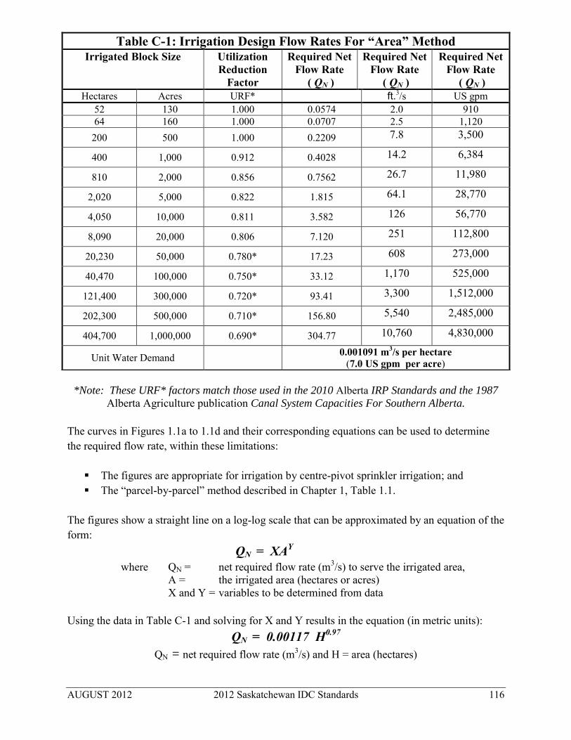
AUGUST 2012 2012 Saskatchewan IDC Standards 116
*Note: These URF* factors match those used in the 2010 Alberta IRP Standards and the 1987
Alberta Agriculture publication Canal System Capacities For Southern Alberta.
The curves in Figures 1.1a to 1.1d and their corresponding equations can be used to determine the required flow rate, within these limitations:
The figures are appropriate for irrigation by centre-pivot sprinkler irrigation; and The “parcel-by-parcel” method described in Chapter 1, Table 1.1.
The figures show a straight line on a log-log scale that can be approximated by an equation of the form: QN = XAY where QN = net required flow rate (m3/s) to serve the irrigated area, A = the irrigated area (hectares or acres) X and Y = variables to be determined from data Using the data in Table C-1 and solving for X and Y results in the equation (in metric units):
QN = 0.00117 H0.97
QN = net required flow rate (m3/s) and H = area (hectares)
Table C-1: Irrigation Design Flow Rates For “Area” Method Irrigated Block Size Utilization
Reduction Factor
Required Net Flow Rate
( QN )
Required Net Flow Rate
( QN )
Required Net Flow Rate
( QN ) Hectares Acres URF* ft.3/s US gpm
52 130 1.000 0.0574 2.0 910 64 160 1.000 0.0707 2.5 1,120 200 500 1.000 0.2209 7.8 3,500
400 1,000 0.912 0.4028 14.2 6,384
810 2,000 0.856 0.7562 26.7 11,980
2,020 5,000 0.822 1.815 64.1 28,770
4,050 10,000 0.811 3.582 126 56,770
8,090 20,000 0.806 7.120 251 112,800
20,230 50,000 0.780* 17.23 608 273,000
40,470 100,000 0.750* 33.12 1,170 525,000
121,400 300,000 0.720* 93.41 3,300 1,512,000
202,300 500,000 0.710* 156.80 5,540 2,485,000
404,700 1,000,000 0.690* 304.77 10,760 4,830,000
Unit Water Demand 0.001091 m3/s per hectare (7.0 US gpm per acre)

AUGUST 2012 2012 Saskatchewan IDC Standards 117
Solving for X and Y in the combined metric and imperial units
QN = 0.00281 A0.97
QN = net required flow rate (m3/s) and A = area (acres)
The QG can be calculated using the Ec factors shown in Table 1.4.
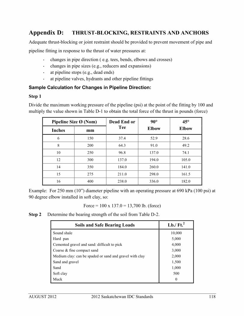
AUGUST 2012 2012 Saskatchewan IDC Standards 118
Appendix D: THRUST-BLOCKING, RESTRAINTS AND ANCHORS Adequate thrust-blocking or joint restraint should be provided to prevent movement of pipe and
pipeline fitting in response to the thrust of water pressures at:
- changes in pipe direction ( e.g. tees, bends, elbows and crosses) - changes in pipe sizes (e.g., reducers and expansions) - at pipeline stops (e.g., dead ends) - at pipeline valves, hydrants and other pipeline fittings
Sample Calculation for Changes in Pipeline Direction:
Step 1
Divide the maximum working pressure of the pipeline (psi) at the point of the fitting by 100 and multiply the value shown in Table D-1 to obtain the total force of the thrust in pounds (force)
Pipeline Size Ø (Nom) Dead End or Tee
90° Elbow
45° Elbow Inches mm
6 150 37.4 52.9 28.6
8 200 64.3 91.0 49.2
10 250 96.8 137.0 74.1
12 300 137.0 194.0 105.0
14 350 184.0 260.0 141.0
15 275 211.0 298.0 161.5
16 400 238.0 336.0 182.0
Example: For 250 mm (10”) diameter pipeline with an operating pressure at 690 kPa (100 psi) at 90 degree elbow installed in soft clay, so:
Force = 100 x 137.0 = 13,700 lb. (force)
Step 2 Determine the bearing strength of the soil from Table D-2.
Soils and Safe Bearing Loads Lb./ Ft.2
Sound shale Hard pan Cemented gravel and sand: difficult to pick Coarse & fine compact sand Medium clay: can be spaded or sand and gravel with clay Sand and gravel Sand Soft clay Muck
10,000 5,000 4,000 3,000 2,000 1,500 1,000 500
0

AUGUST 2012 2012 Saskatchewan IDC Standards 119
Step 3 Divide the total thrust force obtained in Step 1 by the bearing strength of the soil from Table D-2 to determine the needed area (ft.2).
Example: Calculated area:
13,700 / 500 = 27.4 ft.2 = 2.5 m2
Sketches of sample thrust-blocks:
Pipe End
Bend
Cross
Cross with Blank End
Wye
Tee with Blank End

AUGUST 2012 2012 Saskatchewan IDC Standards 120
Appendix E: CONVERSION FACTORS
1 m = 3.281 ft.
1 km = 0.621 mi.
1 hectare = 10,000 m2
1 hectare = 2.471 acres
1 m3 = 1,000 litres
1 dam3 = 1,000 m3
1 dam3 = 0.8107 acre feet
1 m3 = 264.2 US gallons
1 m3 = 220.0 imperial gallons
1 acre inch = 3,630 ft.3
1 lb. (force) = 4.448 N
1 lb. (mass) = 0.454 kg
1 m3/s = 35.31 ft.3/s
1 L/s = 15.85 US gpm
1 kPa = 0.1450 psi
1 ft. = 0.3408 m
1 mi. = 1.609 km
1 acre = 43,560 ft.2
1 acre = 0.4047 hectare
1 ft.3 = 7.481 US gallons
1 ft.3 = 6.229 imperial gallons
1 US gallon = 3.785 litres
1 Imperial gallon = 4.546 litres
1 acre foot = 43,560 ft.3
1 acre foot = 1,233 m3
1 acre foot = 1.233 dam3
1 ft.3/s = 0.02832 m3/s
1 ft.3/s = 28.32 l/s
1 ft.3/s ≈ 1 ac in/hr
1 ft.3/s = 448.8 US gpm
1 ft.3/s = 373.7 imperial gpm
1 psi = 6.895 kPa
Note: In some other publications ft.3/s is written as “cfs” and m3/s is written as “cms”.

AUGUST 2012 2012 Saskatchewan IDC Standards 121
Appendix F: STANDARDS and REFERENCES F.1 Structures F.1.1 Canadian Standards Association (CSA) CSA A5-M Portland Cement CSA A23.1-M Concrete Materials and Methods of Concrete Construction CSS A23.1 Concrete Materials and Methods of Concrete Construction, Section 15.5 Sulfate Attack CSA A23.2-M Methods of Test for Concrete CSA A23.3-M The Design of Concrete Structures for Buildings CAN 3-23.4-M Precast Concrete Materials and Construction CSA S16.1-M Steel Structures for Buildings (Limit States Design) CSA G30.12-M Billet Steel Bars for Concrete Reinforcement CSA G30.18-09 Carbon Steel Bars for Concrete Reinforcement CSA G40.20-M General Requirements for Rolled or Welded Structural Quality Steel CSA G40.21-M Structural Quality Steels CSA G164-M Hot Dip Galvanizing for Irregularly Shaped Articles CSA S16.1-M Limit States Design of Steel Structures CSA W59-M Welded Steel Construction CSA W186-M Welding of Reinforcing Bars in Reinforced Concrete Construction
F.1.2 American Society for Testing and Materials (ASTM) A27/A27M Specification for Steel Castings, Carbon, for General Application A36/A36M Specification for Structural Steel A82 Specification for Steel Wire, Plain, for Concrete Reinforcement A185 Specification for Steel Welded Wire Fabric, Plain, for Concrete
Reinforcement A283/A283M Specification for Low and Intermediate Tensile Strength Carbon Steel
Plates, Shapes and Bars A496 Specification for Steel Wire, Deformed, for Concrete Reinforcement A497 Specification for Steel Welded Wire Fabric, Deformed, for Concrete
Reinforcement A569 Specifications for Steel Carbon (0.15 Maximum, Percent) Hot-Rolled
Steel and Strip, Commercial Quality A570/A570M Specification for Steel, Sheet and Strip, Carbon, Hot-Rolled, Structural
Quality A575/A576 Specification for Steel Bars, Carbon, Merchant Quality A611 Specification for Steel, Sheet, Carbon, Cold-Rolled Structural Quality A615 Specification for Deformed and Plain Billet-Steel Bars for Concrete
Reinforcement A635 Specification for Hot-Rolled Carbon Steel Sheet and Strip, Commercial
Quality, Heavy-Thickness Coils (Formerly Plate) A648 Specification for Steel Wire, Hard Drawn for Prestressing Concrete Pipe A663 Specification for Steel Bars, Carbon, Merchant Quality, Mechanical
Properties

AUGUST 2012 2012 Saskatchewan IDC Standards 122
A675 Specification for Steel Bars, Carbon, Hot-Wrought, Special Quality, Mechanical Properties
C29 Test Method for Unit Weight and Voids in Aggregate C31 Method of Making and Curing Concrete Test Specimens in the Field C33 Specification for Concrete Aggregates C39 Test Method for Compressive Strength of Cylindrical Concrete Specimens C136 Method for Sieve Analysis of Fine and Coarse Aggregates C150 Specification for Portland Cement C172 Method of Sampling Freshly Mixed Concrete C260 Specification for Air-Entraining Admixtures for Concrete C309 Specification for Liquid Membrane-Forming Compounds for Curing
Concrete C497 Methods of Testing Concrete Pipe, Sections, or Tile C595 Specification for Blended Hydraulic Cements C618 Specification for Fly Ash and Raw or Calcined Natural Pozzolan for Use
as a Mineral Admixture in Portland Cement Concrete. C822 Definitions of Terms Relating to Concrete Pipe and Related Products. D395 Test Methods for Rubber Property - Compression Set. D412 Test Methods for Rubber Properties in Tension. D471 Test Method for Rubber Property - Effect of Liquids. D573 Test Method for Rubber - Deterioration in an Air Oven. D698 Test Methods for Moisture-Density Relations of Soils and Soil-Aggregate
Mixtures Using 5.5 lb. (2.49 kg) Rammer and 12 in. (305 mm) Drop D1149 Test Method for Rubber Deterioration-Surface Ozone Cracking in a
Chamber D2049 Test Method for Relative Density of Cohesionless Soils D2240 Test Method for Rubber Property-Durometer Hardness C494 Specification for Chemical Admixtures for Concrete C497 Methods of Testing Concrete Pipe, Sections, or Tile C618 Specification for Fly Ash and Raw or Calcined Natural Pozzolan for Use
as a Mineral Admixture in Portland Cement Concrete. D1-1 Structural Welding Code - Steel D75 Practice for Sampling Aggregates D297 Methods for Rubber Products - Chemical Analysis D395 Test Methods for Rubber Property - Compression Set D412 Test Methods for Rubber Properties in Tension D572 Test Method for Rubber-Deterioration by Heat and Oxygen
F.1.3 American Water Works Association (AWWA) AWWA C501 Cast-Iron Sluice Gates
F.1.4 American Iron and Steel Institute (AISI) AISI Standards for Carbon Steel: G10120, G10130, 10150, G10160, G10180, G10190,
G10200 and 1020

AUGUST 2012 2012 Saskatchewan IDC Standards 123
F.2 Thermoplastic Pipe F.2.1 Canadian Standards Association (CSA) CSA B 137.0 Definition and General Requirements for Thermoplastic Piping. CSA B 137.1 Polyethylene Pipe for Cold Water Service CSA B 137.3 Rigid Polyvinyl Chloride (PVC) Pipe for Pressure Applications CSA B 182.1 Plastic Drain and Sewer Pipe Fittings (100 mm to 150 mm) CSA B 182.2 Plastic Drain and Sewer Pipe Fittings (200 mm to 675 mm)
F.2.2 Canadian General Specifications Board (CGSB) 41-GP-25m Standard for Pipe, Polyethylene, for the Transportation of Liquids 41-GP-29 Ma Corrugated Plastic Drain Tubing NQ 3624-115 Tubing, Plastic Corrugated Drainage
F.2.3 American Society for Testing and Materials (ASTM) D 792 Method of Test for Specific Gravity and Density of Plastics by
Displacement D 618 Methods of Conditioning Plastics and Electrical Insulating Materials for
Testing D 883 Nomenclature Relating to Plastics D1248 Specifications for Polyethylene Plastics Molding and Extrusion Materials D1505 Method of Test for Density of Plastics by Density-Gradient Technique D1598 Test Method for Time-To-Failure of Plastic Pipe Under Constant Internal
Pressure D1599 Test Method for Short-Time Hydraulic Failure Pressure of Plastic Pipe,
Tubing and Fittings D1784 Specifications for Rigid Poly (Vinyl Chloride), (PVC) Compounds and
Chlorinated Poly (Vinyl Chloride) (CPVC) Compounds D2122 Method for Determining Dimensions of Thermoplastic Pipe and Fittings D2152 Test Method for Degree of Fusion of Extruded Poly (Vinyl Chloride)
(PVC) Pipe and Moulded Fittings by Acetone Immersion D2239 Specifications for Polyethylene (PE) Plastic Pipe (SDR-PR) D2241 Standard Specification for PVC Pressure Rated Pipe (SDR Series) D2321 Standard Practice for Underground Installation of Thermoplastics Pipe for
Sewers and Other Gravity Flow Applications D2444 Test Method for Impact of Thermoplastic Pipe and Fittings by Means of a
Tap (Falling Weight) D2657 Heat Joining Polyolefin Pipe and Fittings. D2672 Specifications for Bell-End Poly (Vinyl Chloride) (PVC) Pipe. D2774 Recommended Practice for Underground Installation of Thermoplastic
Pressure Piping D2837 Method for Obtaining Hydrostatic Design Basis for Thermoplastic Pipe
Materials. D3034 Standard Specification for Type PSM PolyVinyl Chloride (PVC) Sewer
Pipe and Fittings

AUGUST 2012 2012 Saskatchewan IDC Standards 124
D3037 Specification for Polyethylene (PE) Plastic Pipe (SDR-PR) Based on Controlled Outside Diameter (OD Base - to 150 mm Diameter Only).
D3139 Specification for Joints for Plastic Pressure Pipes Using Flexible Elastomeric Seals.
D3212 Specification for Joints for Drain and Sewer Plastic Pipes Using Flexible Estomeric Seals
D3261 Butt Head Fusion for PE Plastic Fittings for PE Plastic Pipe and Tubing D3350 Standard Specification for Polyethylene Plastic Pipe and Fittings Material F405 Corrugated Polyethylene Tubing and Fittings F412 Definitions of Terms Relating To Plastic Piping Systems F442 Specification for Chlorinated Polyvinyl Chloride (PVC) Plastic Pipe
(SDR-PR) F679 Standard Specification for Polyvinyl Chloride (PVC) Large-Diameter
Plastic Gravity Sewer Pipe and Fittings F714 Standard Specification for Polyethylene (PE) Plastic Pipe (SDR-PR)
Based on Outside Diameter F894 Specification for Polyethylene (PE) Large Diameter Profile Wall Sewer
and Drain Pipe
F.2.4 American Water Works Association (AWWA) C605 Underground Installation of Polyvinyl Chloride (PVC) Pressure Pipe and
Fittings for Water C900 Polyvinyl Chloride (PVC) Pressure Pipe and Fabricated Fittings (4” – 12”) C905 Polyvinyl Chloride (PVC) Pressure Pipe and Fabricated Fittings (14” – 48”) C906 Polyethylene (PE) Pressure Pipe and Fittings, 4 in. (100 mm) through 63 in.
(1,600 mm), for Water Distribution and Transmission C907 Polyvinyl Chloride (PVC) Pressure Fittings C908 PVC Self-Tapping Saddle Tees for Use on PVC Pipe C909 Molecularly Oriented Polyvinyl Chloride Pressure Pipe
F.2.5 Other Standards: ANSI / ASABE / SCS ANSI/ASAE S376.2 January 1998 (R2004) Design, Installation and Performance of Underground, Thermoplastic
Irrigation Pipelines ASAE EP 369 March 1982 Design of Agricultural Drainage Pumping Plants ASAE EP463.2 November 2009 Design, Construction, and Maintenance of Subsurface Drains in Arid
and Semiarid Areas ASAE EP479 March 1990 (R2005) Design, Installation and Operation of Water Table Management
Systems for Subirrigation/Controlled Drainage in Humid Regions ASAE EP480 March 1998 (R2008) Design of Subsurface Drains in Humid Areas SCS 430 – DD Irrigation Water Conveyance, Pipeline (High Pressure Underground
Plastic)

AUGUST 2012 2012 Saskatchewan IDC Standards 125
Uni-bell PVC Pipe Association Handbook of PVC Pipe Design and Construction, 4 th Edition, 2nd Printing, 2005 Uni-bell PVC Pipe Association PVC Force Main Design, UNI-TR-6-97, 1997
F.3 Steel Pipe CSA G401 Corrugated steel pipe products ASTM A796 / A796M Standard Practice for Structural Design of Corrugated Steel Pipe,
Pipe-Arches, and Arches for Storm and Sanitary Sewers and Other Buried Applications
ASTM A798 / A798M Standard Practice for Installing Factory-Made Corrugated Steel Pipe for Sewers and Other Applications
F.4 Concrete Cylinder Pipe ASTM C361 Reinforced Concrete Low Head Pipe AWWA C301 Standard for Prestressed-Concrete Pressure Pipe, Steel-Cylinder Type AWWA C302 Reinforced Concrete Pressure Pipe, Noncylinder Type AWWA C303 Standard for Concrete Pressure Pipe, Bar-Wrapped, Steel-Cylinder Type
F.5 Other References F.5.1 American Water Works Association AWWA Manual M9 Concrete Pressure Pipe AWWA Manual M9 - Concrete Pressure
Pipe. AWWA Manual No. M23 PVC Pipe - Design and Installation, 1980
F.5.2 Uni-Bell PVC Pipe Association UNI-B-I-95 Recommended Specifications for Thermoplastic Pipe Joints, Pressure and
Non-pressure Applications, 1995 UNI-B-11 Uni-Bell Large Diameter PVC Pressure Pipe UNI-TR-6-97 PVC Force Main Design UNI-TR-7-01 Thermoplastic Pressure Pipe Design and Selection, 2001 Installation Guide for PVC Pressure Pipe
F.5.3 U.S. Bureau of Reclamation Design of Small Canal Structures, 1974, revised 1978 Design of Small Dams Hydraulic Design of Stilling Basins and Energy Dissipaters, 1974
F.5.4 Miscellaneous Publications Channel Systems Design for Southern Alberta Manual, 1987, including the October 1989
Addendum No. 1 “Pipeline System Design Criteria”, Alberta Agriculture and Rural Development

AUGUST 2012 2012 Saskatchewan IDC Standards 126
Concepts of Water Hammer and Air Entrapment in the Filling and Testing of Pipelines, Reprinted by Canron West Pipe
Concrete Pipe Handbook, American Concrete Pipe Association Conservation and Development Branch, Saskatchewan Agriculture November 1982
Design Manual: Water Development Engineering Services Handbook of Steel Drainage and Highway Construction Products, American Iron and
Steel Institute Hydraulic Structures, C.D. Smith, University of Saskatchewan Printing Services Irrigation Rehabilitation Program Design and Construction Standards, Alberta
Government, Agriculture and Rural Development by IRP Standards Review Committee, Irrigation Secretariat, April 26, 2010
Materials for Subsurface Land Drainage Systems, by Stuyt, Dierickx and Beltran. Irrigation and Drainage Paper #60 (Rev. 1) 2005, Food and Agriculture Organization (FAO) of the United Nations
Open-Channel Hydraulics, V. T. Chow, McGraw-Hill Overshot Gate Discharge Characteristics, MPE Engineering Principles of Farm Irrigation System Design, Larry G. James, John Wiley & sons, Inc.,
1988 Problemes de drainage: diagnostic et corrections, Victor Savoie, Quebec ministere de
l’Agriculture, Pecheries, et Alimentation, 1 fevrier 2012. St. Mary Main Canal Rehabilitation Guidelines, Volume IV, Structure Design Criteria Saskatchewan Water Corporation, Sprinkler Irrigation Design Guidelines, Operations
Division, West-Central Region, April, 1988. Soil Mechanics, Lambe & Whitman The Occupational Health and Safety Act, 1993 and The Occupational Health and Safety
Regulations, 1996. Statutes of Saskatchewan. Saskatchewan Labour Relations and Workplace Safety.
Water Control Structures Selected Design Guidelines for Alberta Transportation, Civil Projects Branch and Alberta Environment by Mack-Slack Associates, November, 2004
Water Distribution Modeling. 1st ed., by Walski, Chase, and Savic. Haestad Press, Waterbury, CT, U.S.A. 2001


![Xcelsius Best Practises[1]](https://static.fdocuments.in/doc/165x107/547af7fdb4af9fce158b4d11/xcelsius-best-practises1.jpg)