Sasha Babenko Mike Gardner - IEEE 802 · Sasha Babenko Mike Gardner IEEE P802.3bp Reduced Twisted...
23
Sasha Babenko Mike Gardner IEEE P802.3bp Reduced Twisted Pair Gigabit Ethernet PHY Task Force
Transcript of Sasha Babenko Mike Gardner - IEEE 802 · Sasha Babenko Mike Gardner IEEE P802.3bp Reduced Twisted...

Sasha Babenko
Mike Gardner
IEEE P802.3bp Reduced Twisted Pair Gigabit Ethernet PHY Task Force

Mehmet Tazebay – Broadcom CorporationJames Lawlis, Douglas Oliver – FordKirsten Matheus - BMW
2IEEE P802.3bp Reduced Twisted Pair Gigabit Ethernet PHY Task Force

IntroductionTest samples descriptionTest setupTest resultsConclusions
3IEEE P802.3bp Reduced Twisted Pair Gigabit Ethernet PHY Task Force

4IEEE P802.3bp Reduced Twisted Pair Gigabit Ethernet PHY Task Force
We focused on the entire communication channel between two Ethernetnodes, which includes the two ECU connectors, cable and, in some cases,inline connectors.
Only frequency response of the channels was measured. The purpose ofthe study was twofold:- To investigate IL/RL at certain temperatures;- To investigate if there is a permanent degradation to IL/RL after
exposing assemblies to different temperatures.
Definitions:IL – Insertion Loss (SDD21)RL – Return Loss (SDD22)Frequency measurements were taken at the following temperatures :
- 40 C (required per USCAR-2, GMW3191 – Classes 1, 2 & 3)+23 C (common temperature for most tests)+85 C (required per USCAR-2, GMW3191 – Class 1)+105 C (required per GMW3191; USCAR-2 requires 100 C – Class 2)+125 C (required per USCAR-2, GMW3191 – Class 3)
Per GMW3191 and USCAR-2:Class 1 – passenger compartmentClass 2 – under the hood or on chassisClass 3 – on engine
Test samples were not subjected to mechanical or environmentalconditioning prior to this test.
5IEEE P802.3bp Reduced Twisted Pair Gigabit Ethernet PHY Task Force
Measurements were taken on entire communication channels 10m and15m in total length with up to 4 in-lines.
All samples are made with stranded copper wire.
Sample nomenclature:
Sample 1 – 22 awg PP/PVC (0.34mm2)_15m_no inlines_Cable Type A_Connector Type 1Sample 2 – 22 awg PP/PVC (0.34mm2)_15m_five 3m links_4 inlines_Cable A_Connector 1Sample 5 – 22 awg PP/PVC (0.34mm2)_15m_no inlines_Cable A_Connector 2Sample 6 – 22 awg PP/PVC (0.34mm2)_15m_five 3m links_4 inlines_Cable A_Connector 2/3*Sample 3 – 28 awg PP Shielded (0.08mm2)_10m_five 2m links_4 inlines_Cable B_Connector 1Sample 4 – 25 awg PVC/PVC (0.18mm2)_10m_five 2m links_4 inlines_Cable C_Connector 1
(* connector type 2 as ECU connectors; connector type 3 as inline connectors)
6IEEE P802.3bp Reduced Twisted Pair Gigabit Ethernet PHY Task Force

We have used a cardboard drum 12” diameter (30.5 cm) that allowedeach wrap of cable to be ~1m. This allowed us to test up to 15m links in achamber that is 24”W_21”H_24”D.
Drum with cable assembly and the thermal chamber:
7IEEE P802.3bp Reduced Twisted Pair Gigabit Ethernet PHY Task Force

4-port Vector Network Analyzer capable of 300 kHz – 20 GHz was used.Setup was calibrated to remove the effects of SMA hookup lines.For simplicity, measurement results include SMA test fixtures with
headers and entire communication channels.
VNA test setup:
8IEEE P802.3bp Reduced Twisted Pair Gigabit Ethernet PHY Task Force

Two test sequences were used.First sequence had 8 steps as outlined below (_01 through _08) with
their respective temperature settings. It was used to ensure that there isno damage to the assemblies by verify that IL/RL values would returnback to their original values after each extreme temperature.
Four entire channel assemblies were tested using this sequence.Data for each step 01 through 08 is identified with “_01 ... _08” for
easier tracking of test results.
9IEEE P802.3bp Reduced Twisted Pair Gigabit Ethernet PHY Task Force

Second sequence had only 6 steps as outlined below (_01, _02, _03,_05, _07, _08) with their respective temperature settings. After it wasproven using the first test sequence that extreme temperatures do notpermanently degrade the IL/RL, second more streamlined sequence wasused where 23C measurements _04 and _06 were skipped.
Two entire channel assemblies were tested using this sequence.Data for each step 01 through 08 is identified with “_01 ... _08” for
easier tracking of test results.
10IEEE P802.3bp Reduced Twisted Pair Gigabit Ethernet PHY Task Force

Sample 1 – 22 awg PP/PVC (0.34mm2)_15m_no inlines_Cable Type A_Connector Type 1
11IEEE P802.3bp Reduced Twisted Pair Gigabit Ethernet PHY Task Force

Sample 1 – 22 awg PP/PVC (0.34mm2)_15m_no inlines_Cable Type A_Connector Type 1
12IEEE P802.3bp Reduced Twisted Pair Gigabit Ethernet PHY Task Force

Sample 2 – 22 awg PP/PVC (0.34mm2)_15m_five 3m links_4 inlines_Cable A_Connector 1
13IEEE P802.3bp Reduced Twisted Pair Gigabit Ethernet PHY Task Force

Sample 2 – 22 awg PP/PVC (0.34mm2)_15m_five 3m links_4 inlines_Cable A_Connector 1
14IEEE P802.3bp Reduced Twisted Pair Gigabit Ethernet PHY Task Force
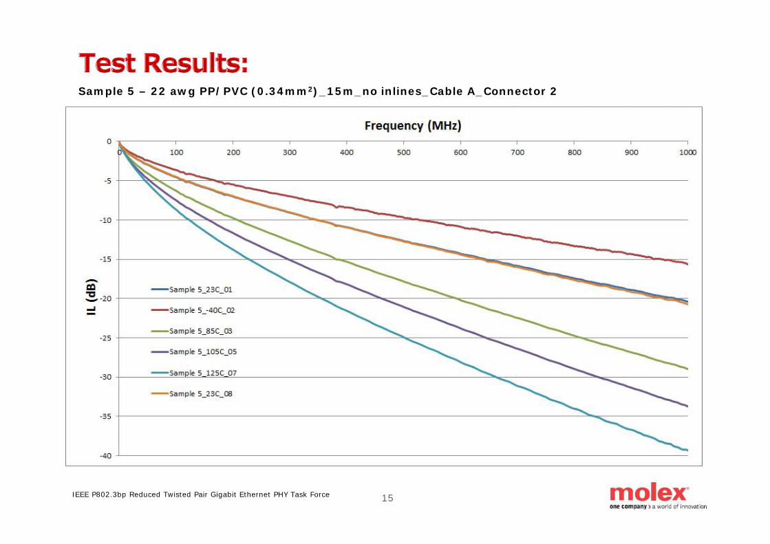
Sample 5 – 22 awg PP/PVC (0.34mm2)_15m_no inlines_Cable A_Connector 2
15IEEE P802.3bp Reduced Twisted Pair Gigabit Ethernet PHY Task Force

Sample 5 – 22 awg PP/PVC (0.34mm2)_15m_no inlines_Cable A_Connector 2
16IEEE P802.3bp Reduced Twisted Pair Gigabit Ethernet PHY Task Force

Sample 6 – 22 awg PP/PVC (0.34mm2)_15m_five 3m links_4 inlines_Cable A_Connector 2/3*(* connector type 2 as ECU connectors; connector type 3 as inline connectors)
17IEEE P802.3bp Reduced Twisted Pair Gigabit Ethernet PHY Task Force
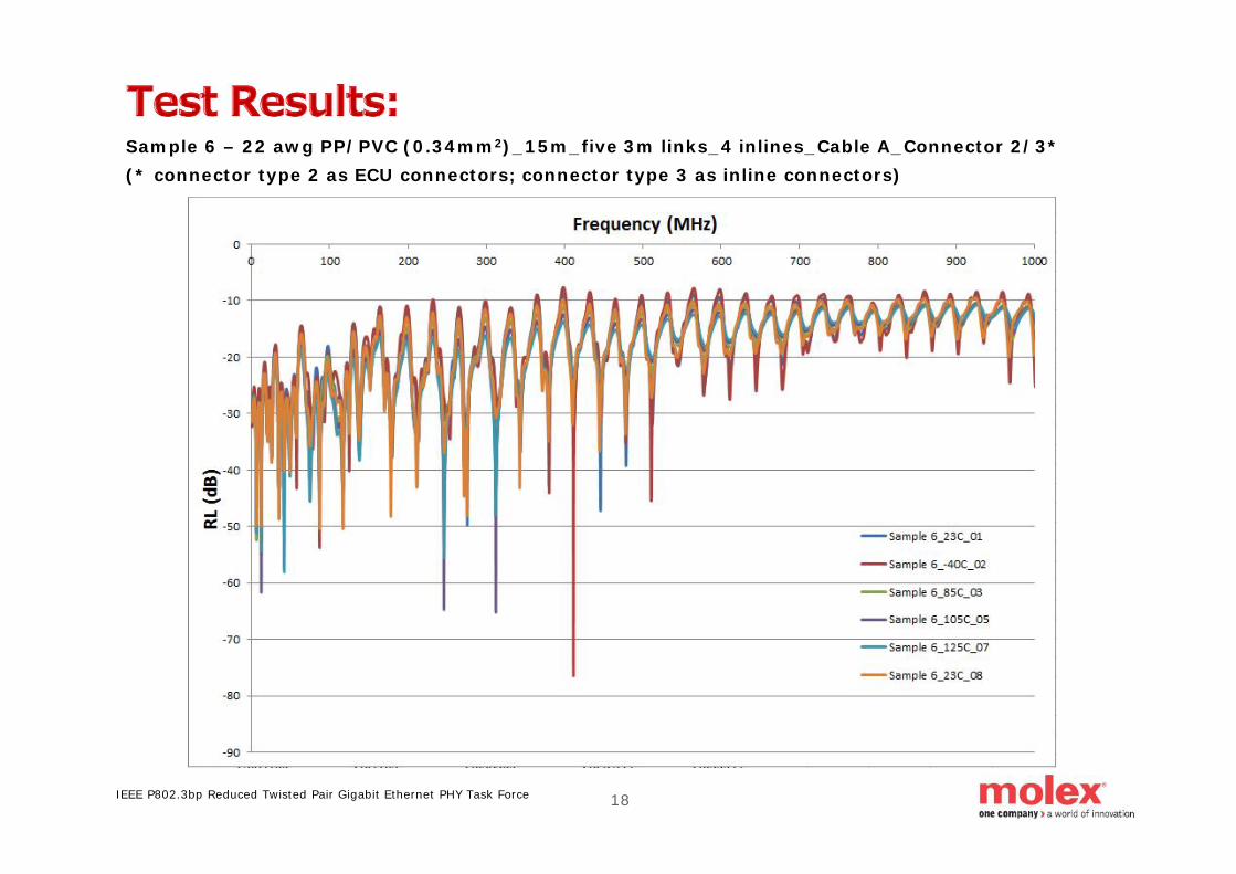
Sample 6 – 22 awg PP/PVC (0.34mm2)_15m_five 3m links_4 inlines_Cable A_Connector 2/3*(* connector type 2 as ECU connectors; connector type 3 as inline connectors)
18IEEE P802.3bp Reduced Twisted Pair Gigabit Ethernet PHY Task Force

Sample 3 – 28 awg PP Shielded (0.08mm2)_10m_five 2m links_4 inlines_Cable B_Connector 1
19IEEE P802.3bp Reduced Twisted Pair Gigabit Ethernet PHY Task Force

Sample 3 – 28 awg PP Shielded (0.08mm2)_10m_five 2m links_4 inlines_Cable B_Connector 1
20IEEE P802.3bp Reduced Twisted Pair Gigabit Ethernet PHY Task Force

Sample 4 – 25 awg PVC/PVC (0.18mm2)_10m_five 2m links_4 inlines_Cable C_Connector 1
21IEEE P802.3bp Reduced Twisted Pair Gigabit Ethernet PHY Task Force
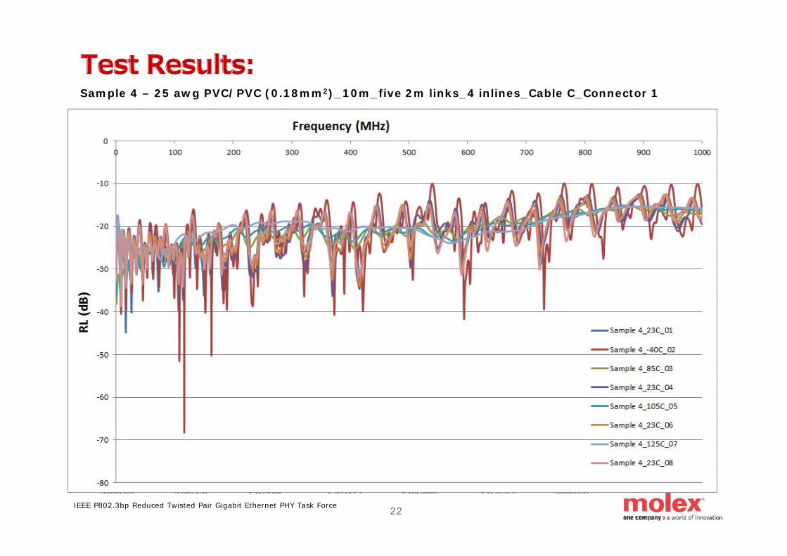
Sample 4 – 25 awg PVC/PVC (0.18mm2)_10m_five 2m links_4 inlines_Cable C_Connector 1
22IEEE P802.3bp Reduced Twisted Pair Gigabit Ethernet PHY Task Force

There appears to be no permanent degradation of IL/RLafter extreme temperature exposure (long-term thermalcycling / shock studies would be needed to fully verifythis)Higher temperatures definitely degrade IL/RLperformance and this must be taken into account duringlimit selection and later during production and systemimplementationSpecial attention must be paid to raw cable performance(dielectric material properties play a big role in assemblyperformance)In-line connections and untwist of diff pairs around endconnectors and in-line connectors may create noticeableresonances (periodic IL suck outs / dips)
23IEEE P802.3bp Reduced Twisted Pair Gigabit Ethernet PHY Task Force