SAS Bay Bridge Erection Equipment
9
SAS Bay Bridge Erection Equipment
Transcript of SAS Bay Bridge Erection Equipment

SAS BAY BRIDGE ERECTION EQUIPMENT allnorth.com
SAS Bay BridgeErection Equipment

SAS BAY BRIDGE ERECTION EQUIPMENT allnorth.com
About Us Allnorth is a multidisciplinary engineering and technical services consulting company serving clients in the oil and gas, mining, infrastructure, and pulp and paper sectors.
With offices across Canada, we provide a single point of contact for clients looking for smart and practical solutions to their project needs.
We are focused on serving our clients and have developed extensive experience and strong client relationships in the sectors we serve.
At Allnorth we strongly believe that providing successful client relationships is the reason we are in business,and delivering the best service in our industry is how we will grow.
SAS BAY BRIDGE ERECTION EQUIPMENT allnorth.com
SAS Bay Bridge
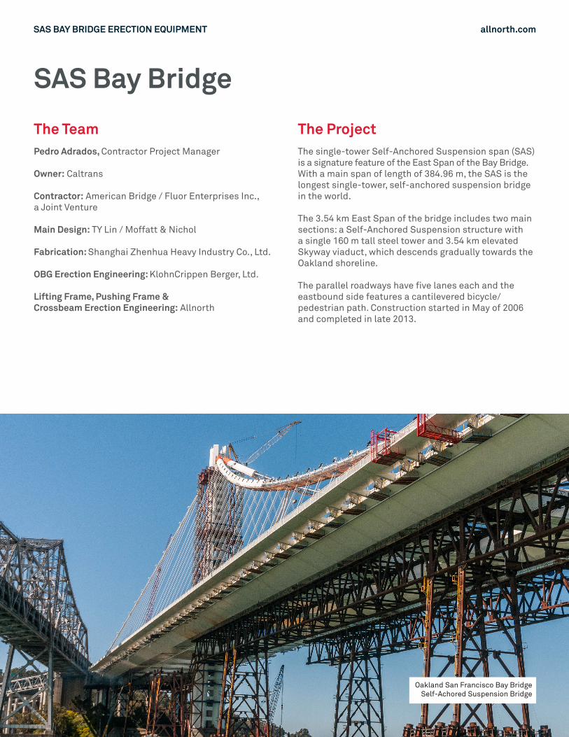
The Team The ProjectPedro Adrados, Contractor Project Manager
Owner: Caltrans
Contractor: American Bridge / Fluor Enterprises Inc.,a Joint Venture
Main Design: TY Lin / Moffatt & Nichol
Fabrication: Shanghai Zhenhua Heavy Industry Co., Ltd.
OBG Erection Engineering: KlohnCrippen Berger, Ltd.
Lifting Frame, Pushing Frame & Crossbeam Erection Engineering: Allnorth
The single-tower Self-Anchored Suspension span (SAS) is a signature feature of the East Span of the Bay Bridge. With a main span of length of 384.96 m, the SAS is the longest single-tower, self-anchored suspension bridge in the world.
The 3.54 km East Span of the bridge includes two main sections: a Self-Anchored Suspension structure with a single 160 m tall steel tower and 3.54 km elevated Skyway viaduct, which descends gradually towards the Oakland shoreline.
The parallel roadways have five lanes each and the eastbound side features a cantilevered bicycle/ pedestrian path. Construction started in May of 2006 and completed in late 2013.
Oakland San Francisco Bay Bridge Self-Achored Suspension Bridge
SAS BAY BRIDGE ERECTION EQUIPMENT allnorth.com
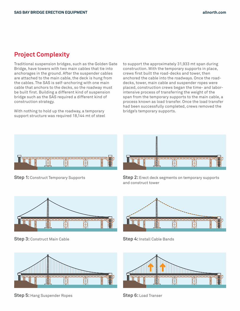
Project ComplexityTraditional suspension bridges, such as the Golden Gate Bridge, have towers with two main cables that tie into anchorages in the ground. After the suspender cables are attached to the main cable, the deck is hung from the cables. The SAS is self-anchoring with one main cable that anchors to the decks, so the roadway must be built first. Building a different kind of suspension bridge such as the SAS required a different kind of construction strategy.
With nothing to hold up the roadway, a temporary support structure was required 18,144 mt of steel
to support the approximately 31,933 mt span during construction. With the temporary supports in place, crews first built the road-decks and tower, then anchored the cable into the roadways. Once the road-decks, tower, main cable and suspender ropes were placed, construction crews began the time- and labor-intensive process of transferring the weight of the span from the temporary supports to the main cable, a process known as load transfer. Once the load transfer had been successfully completed, crews removed the bridge’s temporary supports.
Step 3: Construct Main Cable Step 4: Install Cable Bands
Step 5: Hang Suspender Ropes Step 6: Load Transer
Step 1: Construct Temporary Supports Step 2: Erect deck segments on temporary supports and construct tower
SAS BAY BRIDGE ERECTION EQUIPMENT allnorth.com
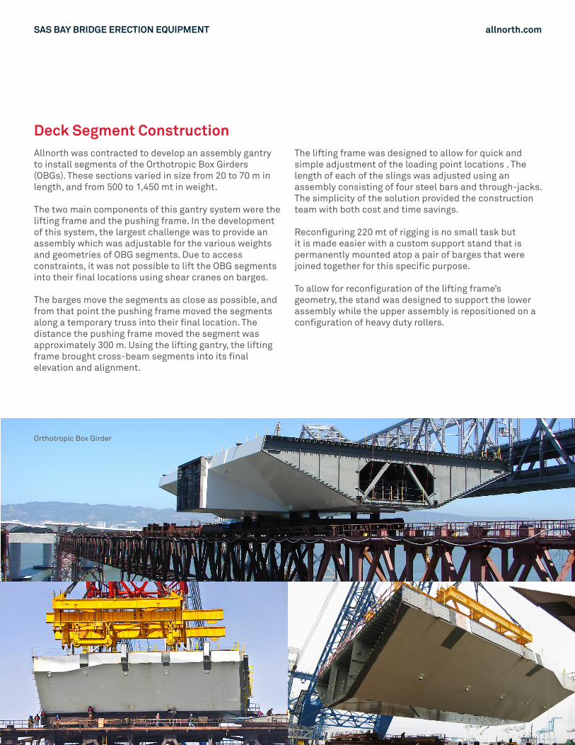
Deck Segment ConstructionAllnorth was contracted to develop an assembly gantry to install segments of the Orthotropic Box Girders (OBGs). These sections varied in size from 20 to 70 m in length, and from 500 to 1,450 mt in weight.
The two main components of this gantry system were the lifting frame and the pushing frame. In the development of this system, the largest challenge was to provide an assembly which was adjustable for the various weights and geometries of OBG segments. Due to access constraints, it was not possible to lift the OBG segments into their final locations using shear cranes on barges.
The barges move the segments as close as possible, and from that point the pushing frame moved the segments along a temporary truss into their final location. The distance the pushing frame moved the segment was approximately 300 m. Using the lifting gantry, the lifting frame brought cross-beam segments into its final elevation and alignment.
The lifting frame was designed to allow for quick and simple adjustment of the loading point locations . The length of each of the slings was adjusted using an assembly consisting of four steel bars and through-jacks. The simplicity of the solution provided the construction team with both cost and time savings.
Reconfiguring 220 mt of rigging is no small task but it is made easier with a custom support stand that is permanently mounted atop a pair of barges that were joined together for this specific purpose.
To allow for reconfiguration of the lifting frame’s geometry, the stand was designed to support the lower assembly while the upper assembly is repositioned on a configuration of heavy duty rollers.
Orthotropic Box Girder
SAS BAY BRIDGE ERECTION EQUIPMENT allnorth.com
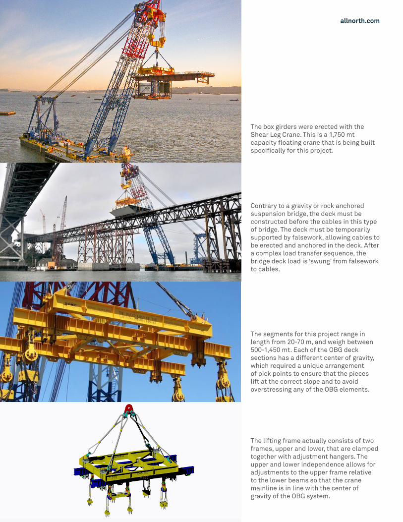
The box girders were erected with the Shear Leg Crane. This is a 1,750 mt capacity floating crane that is being built specifically for this project.
Contrary to a gravity or rock anchored suspension bridge, the deck must be constructed before the cables in this type of bridge. The deck must be temporarily supported by falsework, allowing cables to be erected and anchored in the deck. After a complex load transfer sequence, the bridge deck load is ‘swung’ from falsework to cables.
The segments for this project range in length from 20-70 m, and weigh between 500-1,450 mt. Each of the OBG deck sections has a different center of gravity, which required a unique arrangement of pick points to ensure that the pieces lift at the correct slope and to avoid overstressing any of the OBG elements.
The lifting frame actually consists of two frames, upper and lower, that are clamped together with adjustment hangers. The upper and lower independence allows for adjustments to the upper frame relative to the lower beams so that the crane mainline is in line with the center of gravity of the OBG system.
SAS BAY BRIDGE ERECTION EQUIPMENT allnorth.com
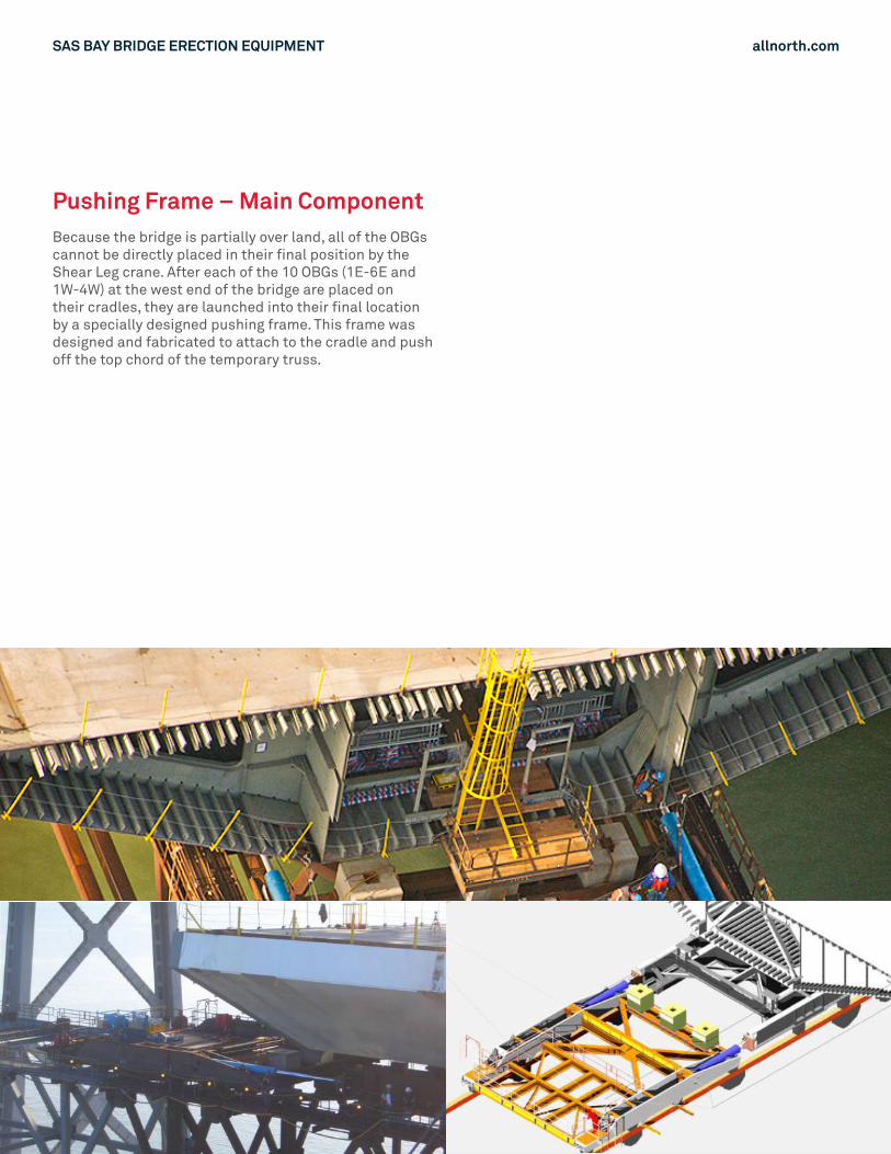
Pushing Frame – Main ComponentBecause the bridge is partially over land, all of the OBGs cannot be directly placed in their final position by the Shear Leg crane. After each of the 10 OBGs (1E-6E and 1W-4W) at the west end of the bridge are placed on their cradles, they are launched into their final location by a specially designed pushing frame. This frame was designed and fabricated to attach to the cradle and push off the top chord of the temporary truss.

SAS BAY BRIDGE ERECTION EQUIPMENT allnorth.com
Crossbeam Erection GantryWhen transporting Crossbeams 1 & 2 from Panel Point 33W to the Crossbeam’s erection location, the Crossbeams and Erection Gantry will be initially supported on Cradle 4W. When the Crossbeam is in its launching position, the south end the gantry beams will be blocked up on E-Line Box Girder to provide sufficient support.

allnorth.com