
SAP_Gorman_V1
30
Swing-Arm Profilometer Michael Gorman Mentors: Richard Pultar Riley Aumiller HNu Photonics
-
Upload
michael-gorman -
Category
Documents
-
view
75 -
download
5
Transcript of SAP_Gorman_V1
Swing-Arm Profilometer
Michael Gorman
Mentors: Richard Pultar Riley Aumiller
HNu Photonics

A tool used to profile the shape and roughness of a surface
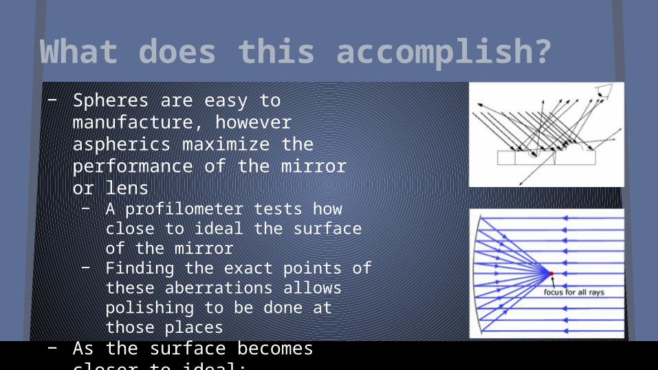
What does this accomplish?− Spheres are easy to
manufacture, however aspherics maximize the performance of the mirror or lens− A profilometer tests how close to
ideal the surface of the mirror − Finding the exact points of these
aberrations allows polishing to be done at those places
− As the surface becomes closer to ideal:− Image resolution increases− More light is focused to a
singular point
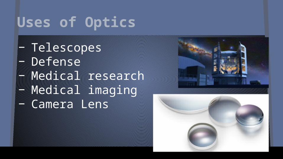
Uses of Optics
− Telescopes− Defense− Medical research− Medical imaging− Camera Lens

Linear Profilomter

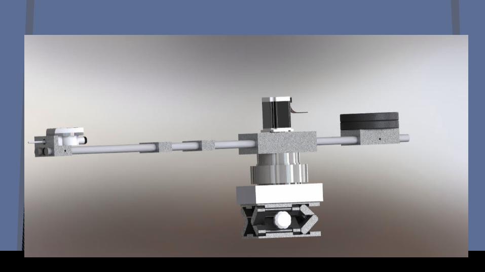
Swing-Arm Profilometer
Why a Swing-Arm?
− Swing-Arm profilometers offer numerous advantages:− Ability to measure larger surfaces
− Linear: 4-6 in− Swing-Arm: 1.5 m
− Cheap to build− Perform “in process” measurements− Extreme Accuracy
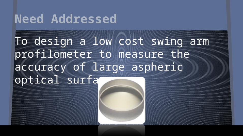
Need Addressed
To design a low cost swing arm profilometer to measure the accuracy of large aspheric optical surfaces.

The Design Process
− Brainstorming− Mock Setup
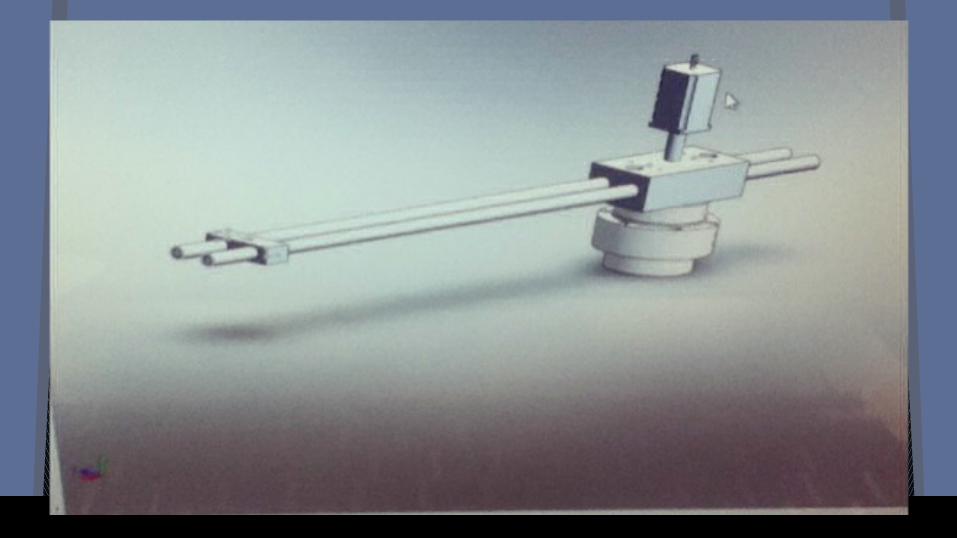
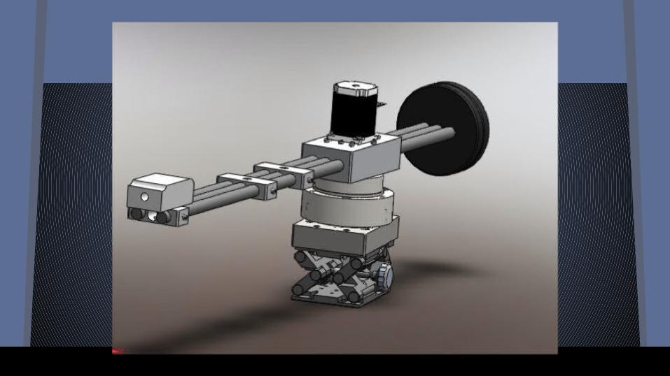
− SolidWorks Assembly− Finite Element Analysis (FEA)
− Vibrations, Deflections, Motion Analysis

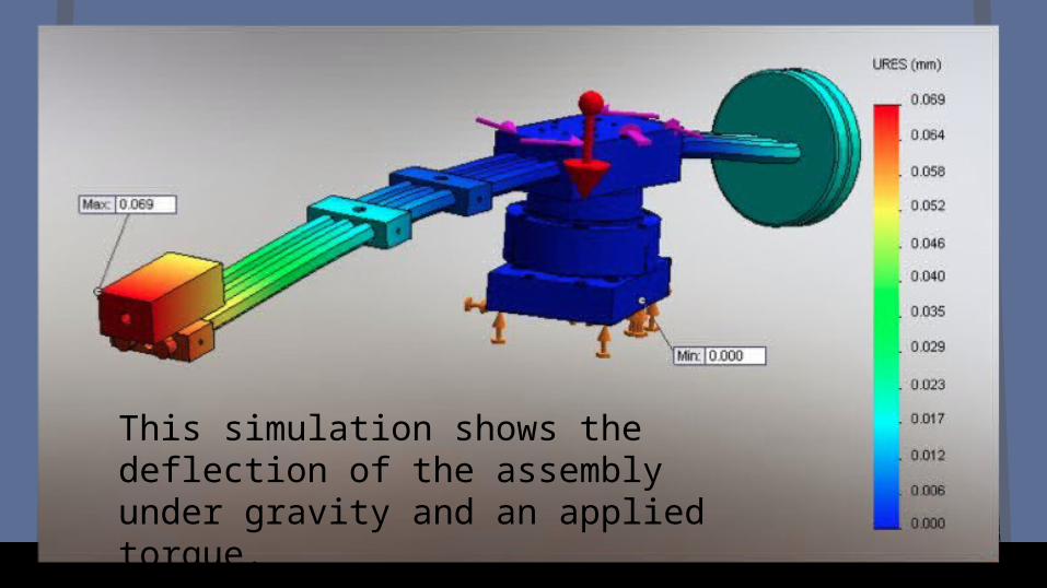
This simulation shows the deflection of the assembly under gravity and an applied torque.


Accomplishments
− Arc Length− 78’’ swing with 25’’ radius− Possibility to have a variable radius
− Hypothetical 360 degree swing− Alterations to placement and use of stepper
motor− Shaft allows spin about central axis.

Programming with MATLab
-Sag-DataPoints and Central Angle Swing
-Central Offset-Ball Offsets

The Sag Equation
-Describes the general shape of a conic surface mirror (hyperbolas, parabolas, spheres and ellipses)
- Where:- C = Curvature- x = Offset from Center- k = Conic Constant
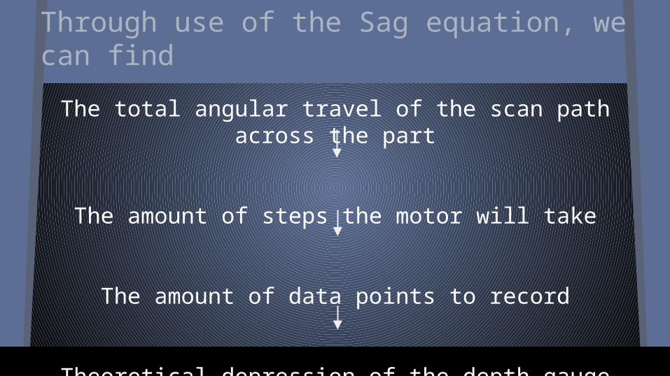
Through use of the Sag equation, we can find
The total angular travel of the scan path across the part
The amount of steps the motor will take
The amount of data points to record
Theoretical depression of the depth gauge at each point
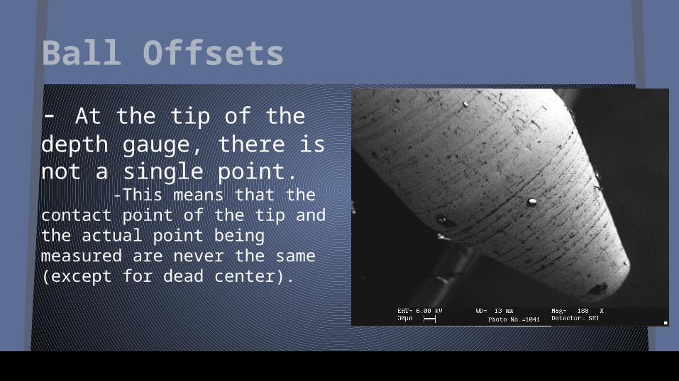
Ball Offsets
- At the tip of the depth gauge, there is not a single point. -This means that the contact point of the tip and the actual point being measured are never the same (except for dead center).

The line points to the spot on the piece that we want measured.
However, you can see that the contact point of the ball is not in line with the point in
question.
Contact Point

By hypothetically pushing the ball to the actual contact point, we can calculate the offset.
By taking the derivatives, of the two functions, at a certain x-offset from the center we can subtract the two and set them equal to zero to find the x’.
This longest line (x’) is how much you’d move the ball up to find the real contact point.
There is an associated angular offset for every contact point we read.
X’
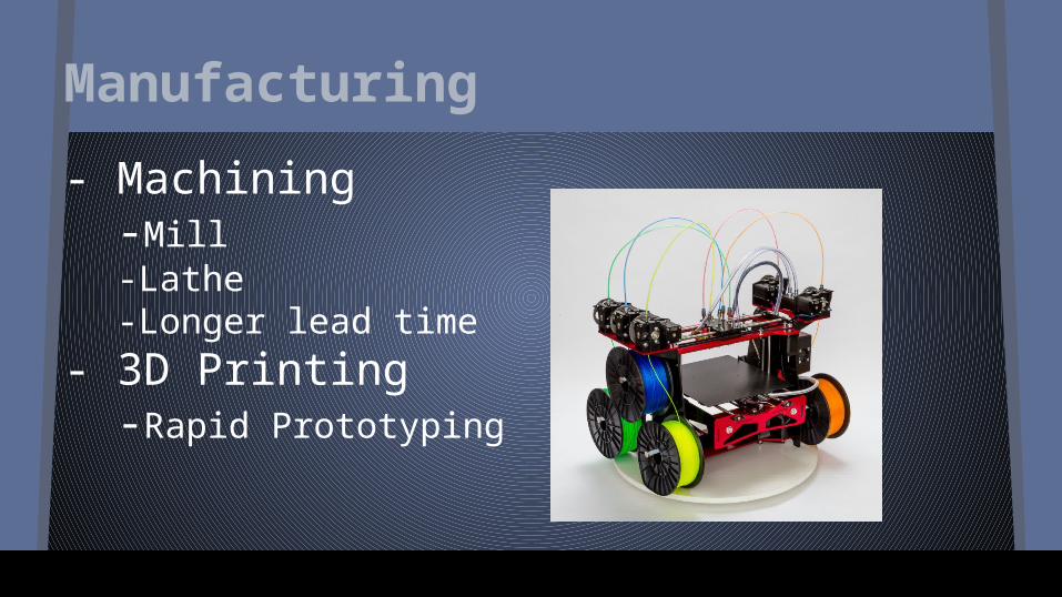
Manufacturing
- Machining-Mill-Lathe-Longer lead time
- 3D Printing-Rapid Prototyping


Assembly
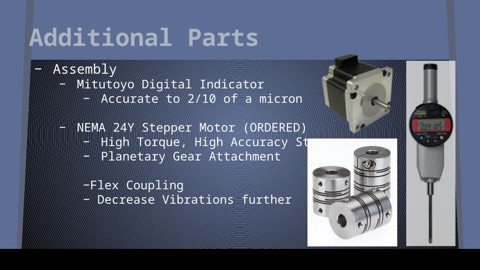
Additional Parts− Assembly
− Mitutoyo Digital Indicator− Accurate to 2/10 of a micron
− NEMA 24Y Stepper Motor (ORDERED)− High Torque, High Accuracy Stepper− Planetary Gear Attachment
−Flex Coupling− Decrease Vibrations further

Final Results- Design and analysis completed
- Design meets needs and requirements for a low cost instrument to accurately measure large aspheric optical surfaces
- Minimal deflections and vibrations. Along with large adaptability
- Programming nearing completion
- Fabrication and procurement in process- Drawings sent to be manufactured (parts lists and
BOM)

Next Steps
- If allotted more time, - Complete assembly of milled parts - Testing of assembly- Document operating procedures and lessons learned
- Predictions for the Future- Optimization of motor torque- Stabilization- Hysteresis

Need Addressed
To design a low cost swing arm profilometer to measure the accuracy of large aspheric optical surfaces.
Thank You
Acknowledgements:- Richard Pultar- Riley Aumiller- Phil Baker- Mike Owens- Mary Liang- HNu Photonics- The Akamai Internship Program
The 2014 Akamai Internship Program is part of the Akamai Workforce Initiative, in partnership with the Univ. of California, Santa Cruz; the Univ. of Hawai'i Institute for Astronomy; and the Thirty Meter Telescope (TMT) International Observatory. Funding is provided by the Air Force Office of Scientific Research (FA9550-10-1-0044); Univ. of Hawai'i; and TMT International Observatory."


