SAP2000 Tutorials - CE463_Lab1
8
1 COLLEGE OF ENGINEERING Department of Civil & Geological Engineering CE 463.3 – Advanced Structural Analysis Lab 1 – Introduction to SAP2000 January 11 th , 2012 T.A: Ouafi Saha Professor: M. Boulfiza Objectives: • Give an over view of the basic commands of SAP2000 • Use of SAP2000 to solve various structural problems • Give the ability to continue a self-learning process 1. Introduction to Computation in Engineering: Engineering process from Conceptual idea to Fabrication (The Finite Element Method – A Practical Course. by G.R. Liu, S.S. Quek) Conceptual Design Modelling Physical, Mathematical, Computational Operational and Economical Simulation Experimental, Analytical and Computational Analysis Listing, Photography, Computer graphics and Virtual reality Design Prototyping Testing Fabrication
-
Upload
ouafi-saha -
Category
Documents
-
view
844 -
download
19
description
Simple starting example for SAP2000 v14
Transcript of SAP2000 Tutorials - CE463_Lab1

1
COLLEGE OF
ENGINEERING Department of Civil & Geological Engineering
CE 463.3 – Advanced Structural Analysis
Lab 1 – Introduction to SAP2000
January 11th, 2012
T.A: Ouafi Saha Professor: M. Boulfiza Objectives:
• Give an over view of the basic commands of SAP2000 • Use of SAP2000 to solve various structural problems • Give the ability to continue a self-learning process
1. Introduction to Computation in Engineering:
Engineering process from Conceptual idea to Fabrication (The Finite Element Method – A Practical Course. by G.R. Liu, S.S. Quek)
Conceptual Design
Modelling Physical, Mathematical, Computational
Operational and Economical
Simulation Experimental, Analytical and Computational
Analysis Listing, Photography,
Computer graphics and Virtual reality
Design
Prototyping
Testing
Fabrication

2
2. Computation Hardware tool:
Simplified scheme for Computer 3. Computation Software tool:
Simplified scheme of a computer software 4. SAP2000: SAP2000 is a program based on Finite Element Method (FEM). It is one of a long list of software package having the FEM as their kernel. A non-exhaustive list is available at this address: http://en.wikipedia.org/wiki/List_of_finite_element_software_packages The program is edited by a company named CSI (Computer and Structure Inc.) founded in 1975. The very first version of SAP was SAP, SOLIDSAP and SAP IV. With the advent of PC computers, SAP was released in two major versions SAP80 and SAP90, basically these two versions and the previous ones was based on TEXT input and output interface. In 1996 the first version of SAP2000 was released, it had an integrated graphical user interface working completely under Microsoft Windows. The choice of SAP2000 software is mainly due to its civil engineering orientation and to its relative ease of use. SAP2000 has an integrated graphical user interface similar to some older version of Autocad’s interface. Various documentation and tutorials are available:
• Built-in help and PDF documentation. • http://www.csiberkeley.com/sap2000/watch-and-learn • google or youtube “sap2000 tutorial” leads to plenty of documents and videos, but try to start
with easiest ones.
Input
Central Unit
Output
Pre-Processor Import, Interactive
Processor Interpretation of data, Detection of Errors, Formation of Sys. Eq., Solve Sys., Iteration
Post-Processor Visualization, Design

3
5. Basic Steps to Solve a Structural Problem using SAP2000: 1. Start-up by choosing units, setting up grids or by choosing a model from the library 2. Define materials, elements properties, loading patterns, analysis cases and combinations 3. Draw the model using the powerful graphic interface and selection and editing tools 4. Assign displacement boundary conditions (supports) 5. Assign loads (forces, moment, displacement, pressure, temperature…) 6. SOLVE system, use simplification if possible 7. Display Output in graphic and/or tabular form 8. Analyze results
6. Examples: 6.1. Simply supported beam http://www.youtube.com/watch?v=IrYnpP2vDp0
Units kN, m, C Material Concrete, Section 30x50cm2, each segment is 1.5m, Two possible ways to model Steps: Start SAP2000 by using: ie http://www.engr.usask.ca/vdi/, or save-as the link and execute it. Login using your nsid. Choose New model > select appropriate units and click on grid only
In the next dialog box enter the appropriate values

4
Close 3D window and choose view for the 2D view Select Define > Section Porpertires > Frame Sections… then click on Add New Properties
Select Concrete and Rectangular section
5
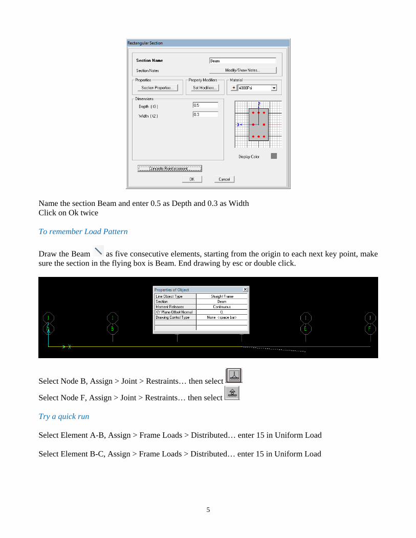
Name the section Beam and enter 0.5 as Depth and 0.3 as Width Click on Ok twice To remember Load Pattern Draw the Beam as five consecutive elements, starting from the origin to each next key point, make sure the section in the flying box is Beam. End drawing by esc or double click.
Select Node B, Assign > Joint > Restraints… then select
Select Node F, Assign > Joint > Restraints… then select Try a quick run Select Element A-B, Assign > Frame Loads > Distributed… enter 15 in Uniform Load Select Element B-C, Assign > Frame Loads > Distributed… enter 15 in Uniform Load

6
Select Node D, Assign > Joint Loads > Forces… enter -45 in Force Global Z Select Node E, Assign > Joint Loads > Forces… enter -22.5 in Force Global Z
Before Solving take a look at the final configuration, particularly Loading Menu Display > Show Load Assigns > Frame/Cable/Tendon… The screen should show the beam like this
Our beam can be treated in two dimensions 3DOF system. This can considerably reduce the size of the problem for a high number of node problems. Menu Analyze > Set Analysis Options… Click on Plane Frame You can see that the only active DOF’s available are the two translations X and Z and one rotation RY.

7
Now we can run the Analysis or F5 or Menu > Analysis > Run Analysis…
Make sure to turn off the analysis of Modal Case Click on Run Now You will be prompted to save your work if it has not been done yet It’s recommended to save your work in a regular basis It’s time to analyze our results and to decide if they are acceptable or need to be reviewed in some way. Neglect self-weight http://www.youtube.com/watch?v=xajE-OhAut8 Check deformed shape, Support reactions Internal forces and moments

8
6.2. Continuous Beam
Unit conversion possibility Loading pattern possibilities Support local axis rotation Displacement loading 6.3. Simple Frame with Complicated loading
Section possibilities Axis Visualization Local and global axis
3 t/m
2 t/m 6 t.m
60
55
15 125
25
25
5t
4t
4t
3.0
4.0
6.0 5.0 3.0
1.5 1.5 2.5
l/2
l/2