Sand Probe Relays Sand Probe Adaptors Sand Probe “Pipe ... · - SAND PROBE ADAPTORS The Adaptor...
38
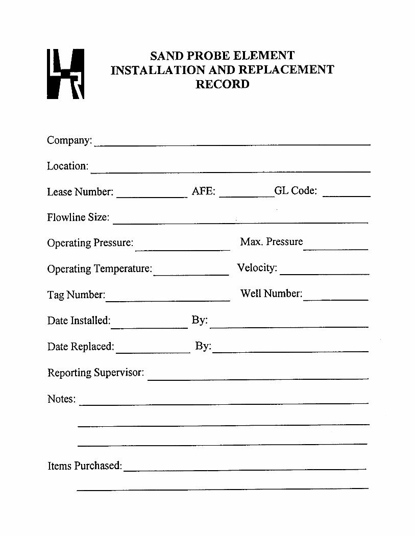
Sand Probe Relays Sand Probe Adaptors Sand Probe “Pipe” Elements Special Manufacture - Adaptor/Elements Special Manufacture - Flange Assemblies & Accessories Sample Quills (Probes) - Injection Quills Product List ______________________________________________________________________________ The listings which follows, depicts our most frequently utilized products and some Special Manufacture items. We can develop and supply unique components for specific applications. An information form is also provided to assist with the design criteria of the unique product required. Red text denotes Special Manufacture products or specific features. ______________________________________________________________________________ - SAND PROBE RELAYS Two Position, Three Way, Flow Control Valves, Media Pressure Operated, with Manual Reset Feature. 10,000 PSI Working Pressure at the Process Connection or Pilot Supply port, (unless stated otherwise). MODEL NUMBER FUNCTION - FEATURES ( F IELD M OUNT M ODELS ) HLR 7550A......................Normally Open, Standard Service. HLR 350-20A..................Normally Open, 15,000 PSI Working Pressure. HLR 7740.........................Normally Closed. MODEL NUMBER FUNCTION - FEATURES ( P ANEL M OUNT M ODELS ) HLR 7930.........................Normally Open. HLR 7930R......................Normally Open, Red Knob. HLR 7935.........................Normally Closed. HLR 150-1.......................Universal Ports (NC,C,NO). Page 1 of 7
Transcript of Sand Probe Relays Sand Probe Adaptors Sand Probe “Pipe ... · - SAND PROBE ADAPTORS The Adaptor...

Sand Probe RelaysSand Probe Adaptors
Sand Probe “Pipe” ElementsSpecial Manufacture - Adaptor/Elements
Special Manufacture - Flange Assemblies & AccessoriesSample Quills (Probes) - Injection Quills
Product List______________________________________________________________________________
The listings which follows, depicts our most frequently utilized products and some SpecialManufacture items. We can develop and supply unique components for specific applications. Aninformation form is also provided to assist with the design criteria of the unique product required.Red text denotes Special Manufacture products or specific features. ______________________________________________________________________________
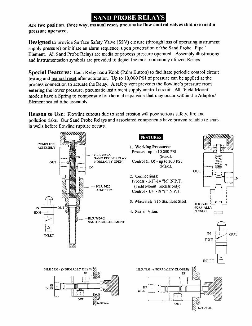
- SAND PROBE RELAYS
Two Position, Three Way, Flow Control Valves, Media Pressure Operated, with ManualReset Feature. 10,000 PSI Working Pressure at the Process Connection or Pilot Supply port,(unless stated otherwise).
MODEL NUMBER FUNCTION - FEATURES (FIELD MOUNT MODELS)
HLR 7550A......................Normally Open, Standard Service.
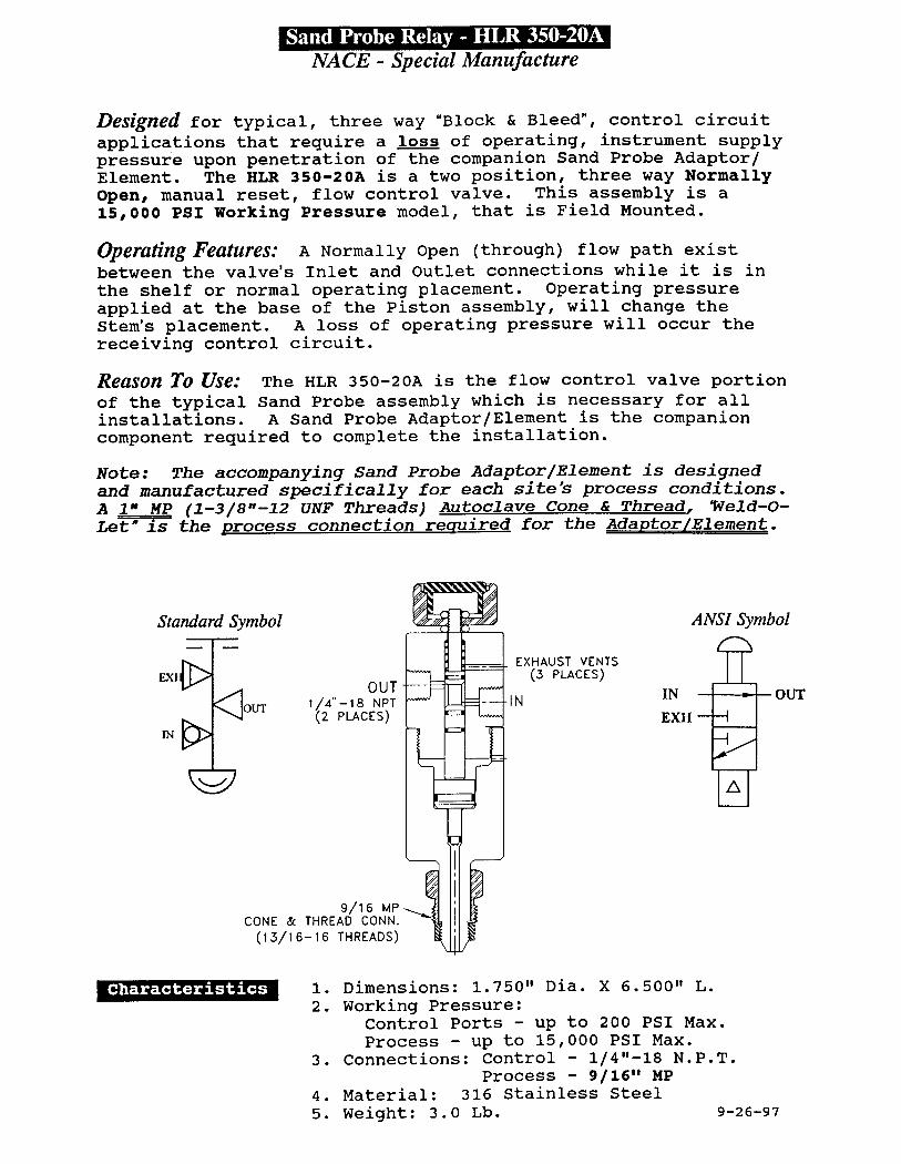
HLR 350-20A..................Normally Open, 15,000 PSI Working Pressure.
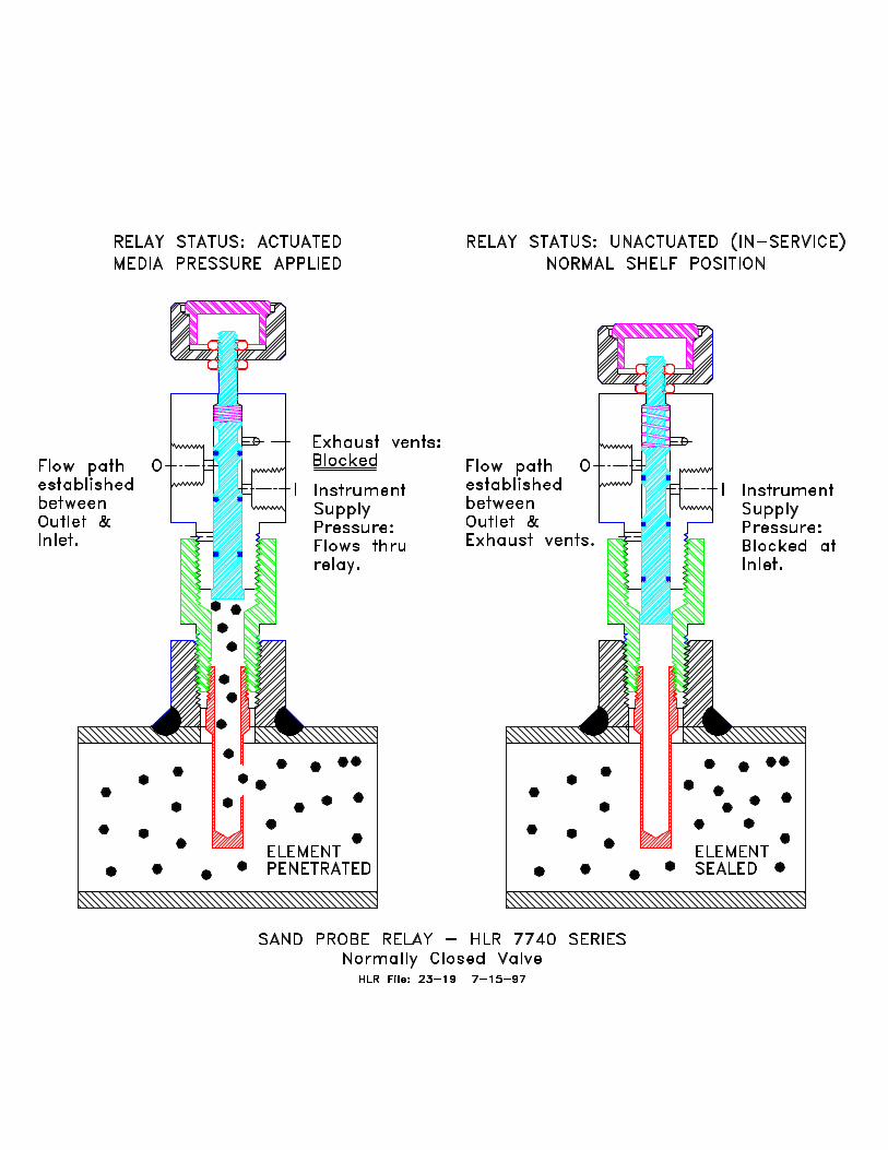
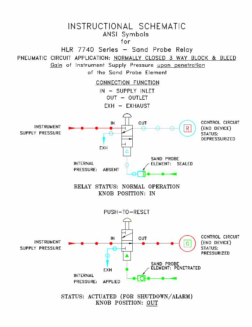
HLR 7740.........................Normally Closed.
MODEL NUMBER FUNCTION - FEATURES (PANEL MOUNT MODELS)
HLR 7930.........................Normally Open.
HLR 7930R......................Normally Open, Red Knob.
HLR 7935.........................Normally Closed.
HLR 150-1.......................Universal Ports (NC,C,NO).
Page 1 of 7

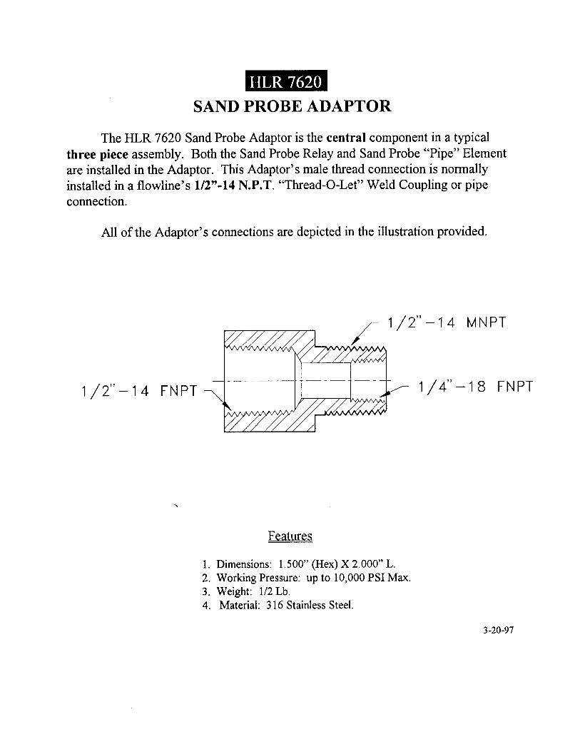
- SAND PROBE ADAPTORS
The Adaptor is the central component of a standard, three piece companion (Relay,Adaptor, “Pipe” Element), field mounted assembly. The Adaptors listed below have a 1/4"-18N.P.T. "Female" Connection for installing a Male tube end, Sand Probe Pipe Element. AllAdaptors are manufactured from 316 Stainless Steel.
MODEL NUMBER CONNECTIONS
HLR 7620........................1/2"-14 N.P.T. Male x Female. (Standard)
HLR 34AE12..................3/4"-14 Male x 1/2"-14 N.P.T. Female.Manufactured upon Order entry only.
- SAND PROBE "PIPE" ELEMENTS
A 1/4"-18 "M" N.P.T. Male Tube End, Sealed Tube component installed within a wellstream’s flowline to provide a sand impingement surface. This component requires a companionSand Probe Adaptor for new installations. See our Order Selection Chart for WorkingPressure/Wall Thickness correlation and order information.
MODEL NUMBER FLOWLINE SIZE & MATERIAL
HLR 7620-2.......................2" Alloy Steel.
HLR 7620-3.......................3" Alloy Steel.
HLR 7620-4.......................4" Alloy Steel.
HLR 7620-6........................6" Alloy Steel.
Note: Sand Probe (Pipe) Elements for flowline sizes larger than 6", are routinely provided asspecial order items. Additionally, any material other than Alloy Steel, will be classified as aSpecial Manufacture item. The Stainless Steel Elements listed, are manufactured after theentry of a Purchase Order only. Specify Grade of Stainless Steel required when ordering.
MODEL NUMBER FLOWLINE SIZE & MATERIAL
HLR 7620-2SS...................2" - Stainless Steel.
HLR 7620-3SS...................3" - Stainless Steel.
HLR 7620-4SS...................4" - Stainless Steel.
HLR 7620-6SS...................6" - Stainless Steel.
Page 2 of 7
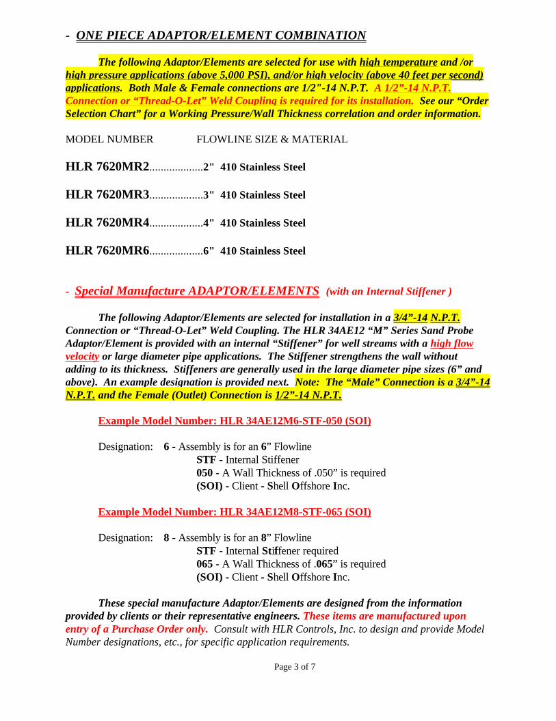
- ONE PIECE ADAPTOR/ELEMENT COMBINATION
The following Adaptor/Elements are selected for use with high temperature and /orhigh pressure applications (above 5,000 PSI), and/or high velocity (above 40 feet per second)applications. Both Male & Female connections are 1/2"-14 N.P.T. A 1/2”-14 N.P.T.Connection or “Thread-O-Let” Weld Coupling is required for its installation. See our “OrderSelection Chart” for a Working Pressure/Wall Thickness correlation and order information.
MODEL NUMBER FLOWLINE SIZE & MATERIAL
HLR 7620MR2...................2" 410 Stainless Steel
HLR 7620MR3...................3" 410 Stainless Steel
HLR 7620MR4...................4" 410 Stainless Steel
HLR 7620MR6...................6" 410 Stainless Steel
- Special Manufacture ADAPTOR/ELEMENTS (with an Internal Stiffener )
The following Adaptor/Elements are selected for installation in a 3/4”-14 N.P.T.Connection or “Thread-O-Let” Weld Coupling. The HLR 34AE12 “M” Series Sand ProbeAdaptor/Element is provided with an internal “Stiffener” for well streams with a high flowvelocity or large diameter pipe applications. The Stiffener strengthens the wall withoutadding to its thickness. Stiffeners are generally used in the large diameter pipe sizes (6” andabove). An example designation is provided next. Note: The “Male” Connection is a 3/4”-14N.P.T. and the Female (Outlet) Connection is 1/2”-14 N.P.T.
Example Model Number: HLR 34AE12M6-STF-050 (SOI)
Designation: 6 - Assembly is for an 6” FlowlineSTF - Internal Stiffener050 - A Wall Thickness of .050” is required(SOI) - Client - Shell Offshore Inc.
Example Model Number: HLR 34AE12M8-STF-065 (SOI)
Designation: 8 - Assembly is for an 8” FlowlineSTF - Internal Stiffener required065 - A Wall Thickness of .065” is required(SOI) - Client - Shell Offshore Inc.
These special manufacture Adaptor/Elements are designed from the informationprovided by clients or their representative engineers. These items are manufactured uponentry of a Purchase Order only. Consult with HLR Controls, Inc. to design and provide ModelNumber designations, etc., for specific application requirements.
Page 3 of 7
- High Pressure “Cone & Thread” Connections (For 1" Medium Pressure Autoclave, Butech, HIP installations)
The Sand Probe “Cone & Thread” Adaptor/Element combinations are utilized in15,000 PSI (and above) Operating Pressure applications. Our special Adaptor/Elements arealso designed according to information provided by clients or their representative engineers. A 1” Medium Pressure (1-3/8”-12-2B “Female” Threads) Connection is required for itsinstallation. High Pressure Adaptor/Elements are manufactured after entry of a confirmingPurchase Order only. Consult with HLR Controls, Inc. to design and provide Model Numberdesignations, etc. for usage of these special manufacture items.
- Special Manufacture Flange Assemblies & Accessories
Some Oil & Gas Producers prohibit the use of threaded couplings or National PipeThreads (N.P.T.) connections on flowlines. We provide “flanged” assemblies for thesespecific requirements. The components required are designed to client specifications andassigned model numbers which will also identify the client. Our description of designationsand some example flange assemblies are provided as next:
Example Model Number: SPF-1.5RTJ-900CS-MOB
Designation: SPF - Sand Probe Flange 1.5RTJ - 1-1/2" Ring Type Joint 900CS - # 900 Series, Carbon Steel Material MOB - Mobil Nigeria Special (Client)
Example Model Number: SPF-1.5RTJ-2500CS-MOB
Designation: SPF - Sand Probe Flange 1.5RTJ - 1-1/2" Ring Type Joint 2500CS - # 2500 Series, Carbon Steel Material MOB - Mobil Nigeria Special (Client)
Example Model Number: SPF-1.5RF-1500CS-PCS
Designation: SPF - Sand Probe Flange 1.5RF - 1-1/2" Raise Face 1500CS - # 1500 Series, Carbon Steel Material PCS - Petronas Carigali Sarawak (Client)
Each of the flange models shown, were provided with special manufacture Sand ProbeAdaptor/Elements. The criteria provided from the listings (as found on the next page) willdetermine the Sand Probe Flange and “Pipe Elements” specific design.
Page 4 of 7

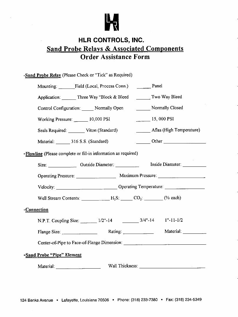
Flowline (Pipe) Size: _________________________
Flowline’s Outside Diameter (O.D.): ______________________
Flowline’s Inside Diameter (I.D.): _______________________
Flange Size or Connection: ___________________________
Material Required: _____________________
Center-of-Pipe to Face-of-Flange Dimension: _____________________
Normal Operating Pressure: ____________________
Maximum Pressure: ______________________
Well Stream Contents: ___________________________________________
H2S ________ CO2 _________ Other: _______________________
Operating Temperature: __________________________________________
Well Stream Velocity: _____________________________________________________
Providing the information from each item listed above, will allow a specific assemblyto be designed from the application criteria. See our Order Assistance Form for a moredetailed listing of options.
* A Special Probe Adaptor/Element component is necessary to complete theFlanged Sand Probe assembly.
Consult with HLR Controls, Inc. to design and provide Model Number designations,etc. for usage of these special manufacture products.
All special manufacture Sand Probe Adaptor/Elements are recognizable by theSPAE 25- prefix designation. These Adaptor/Elements are individually designed forunique (specific) application, process conditions and/or location.
The prefix designation SPAE, will identify Special Probe Adaptor/Element component usage.
Page 5 of 7

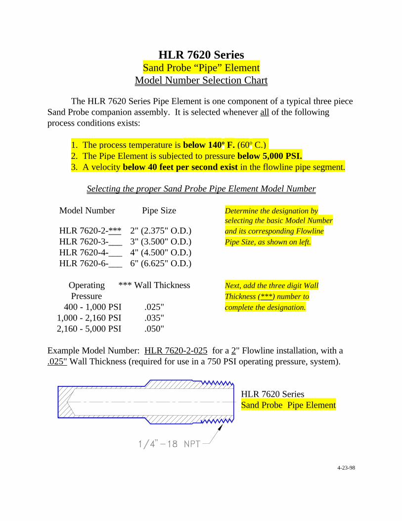
HLR 7620 SeriesSand Probe “Pipe” Element
Model Number Selection Chart
The HLR 7620 Series Pipe Element is one component of a typical three pieceSand Probe companion assembly. It is selected whenever all of the followingprocess conditions exists:
1. The process temperature is below 140o F. (60o C.) 2. The Pipe Element is subjected to pressure below 5,000 PSI.3. A velocity below 40 feet per second exist in the flowline pipe segment.
Selecting the proper Sand Probe Pipe Element Model Number
Model Number Pipe Size Determine the designation byselecting the basic Model Number
HLR 7620-2-*** 2" (2.375" O.D.) and its corresponding Flowline
HLR 7620-3-___ 3" (3.500" O.D.) Pipe Size, as shown on left.
HLR 7620-4-___ 4" (4.500" O.D.)HLR 7620-6-___ 6" (6.625" O.D.)
Operating *** Wall Thickness Next, add the three digit Wall
Pressure Thickness (***) number to
400 - 1,000 PSI .025" complete the designation.
1,000 - 2,160 PSI .035" 2,160 - 5,000 PSI .050"
Example Model Number: HLR 7620-2-025 for a 2" Flowline installation, with a.025" Wall Thickness (required for use in a 750 PSI operating pressure, system).
HLR 7620 Series Sand Probe Pipe Element
4-23-98

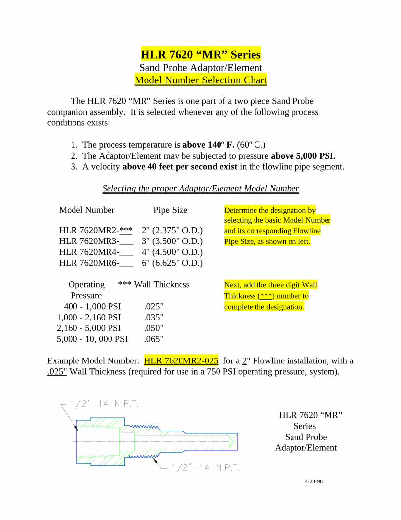
HLR 7620 “MR” SeriesSand Probe Adaptor/Element
Model Number Selection Chart
The HLR 7620 “MR” Series is one part of a two piece Sand Probecompanion assembly. It is selected whenever any of the following processconditions exists:
1. The process temperature is above 140o F. (60o C.) 2. The Adaptor/Element may be subjected to pressure above 5,000 PSI.3. A velocity above 40 feet per second exist in the flowline pipe segment.
Selecting the proper Adaptor/Element Model Number
Model Number Pipe Size Determine the designation byselecting the basic Model Number
HLR 7620MR2-*** 2" (2.375" O.D.) and its corresponding FlowlineHLR 7620MR3-___ 3" (3.500" O.D.) Pipe Size, as shown on left.HLR 7620MR4-___ 4" (4.500" O.D.)HLR 7620MR6-___ 6" (6.625" O.D.)
Operating *** Wall Thickness Next, add the three digit Wall Pressure Thickness (***) number to 400 - 1,000 PSI .025" complete the designation.
1,000 - 2,160 PSI .035" 2,160 - 5,000 PSI .050" 5,000 - 10, 000 PSI .065"
Example Model Number: HLR 7620MR2-025 for a 2" Flowline installation, with a.025" Wall Thickness (required for use in a 750 PSI operating pressure, system).
HLR 7620 “MR”Series
Sand ProbeAdaptor/Element
4-23-98
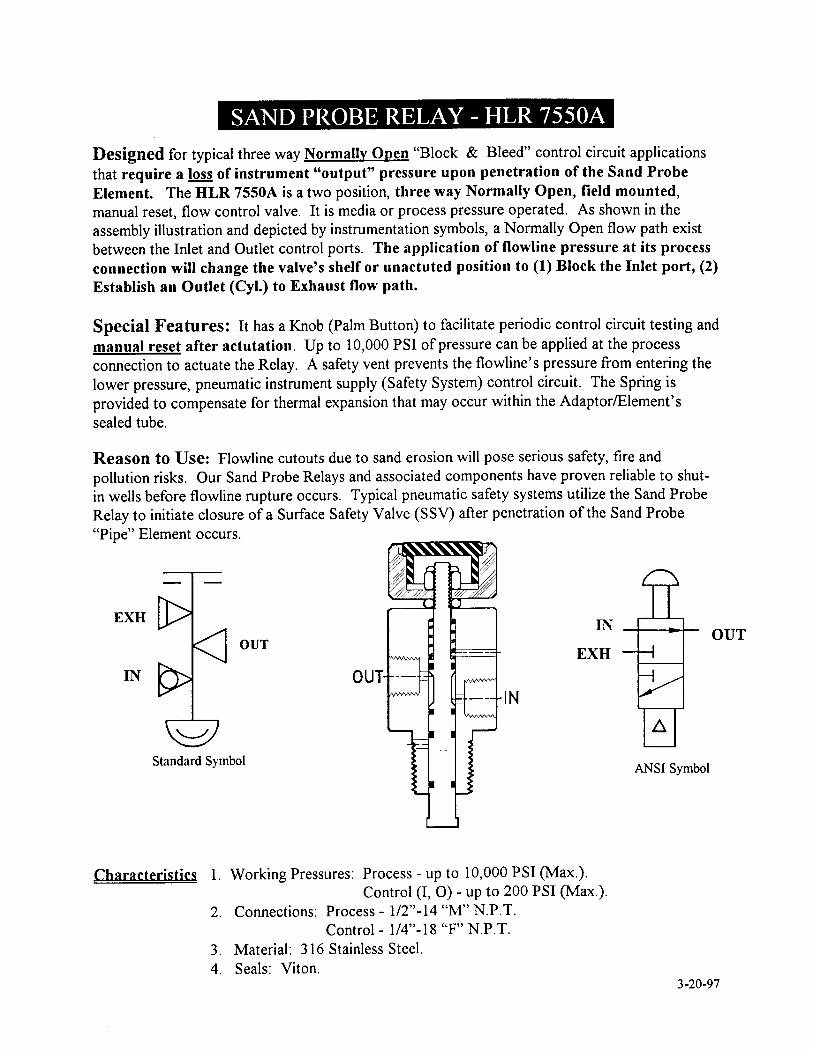
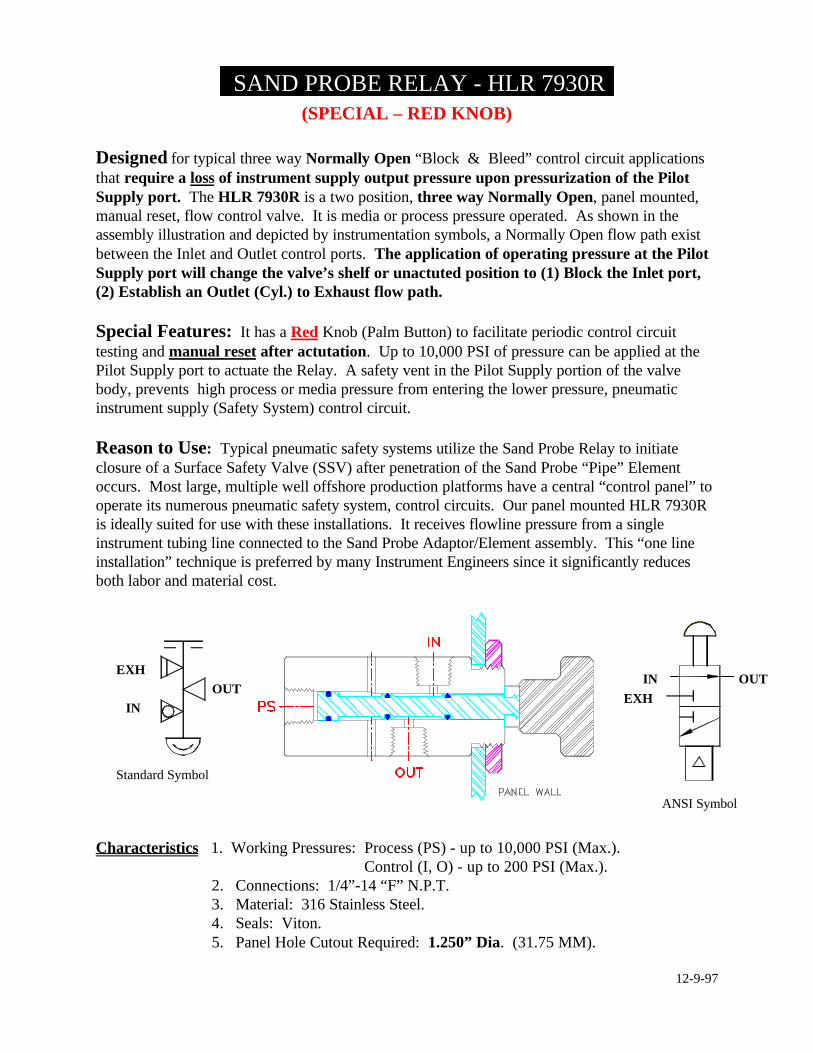
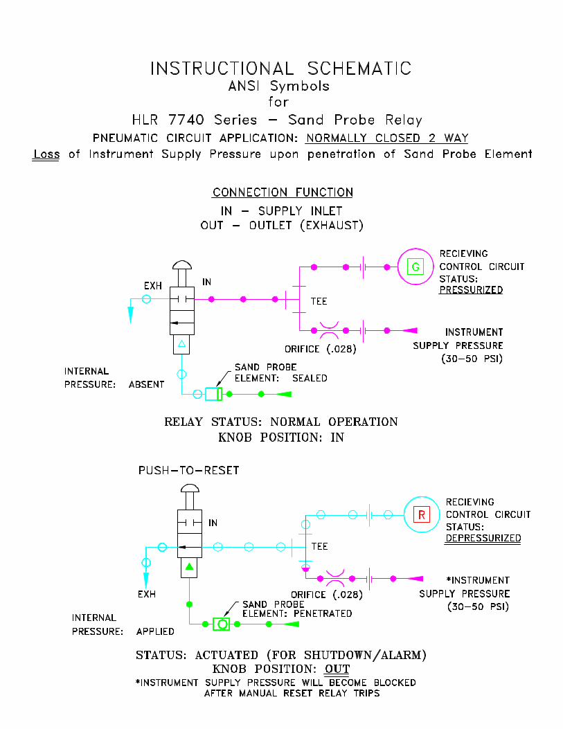
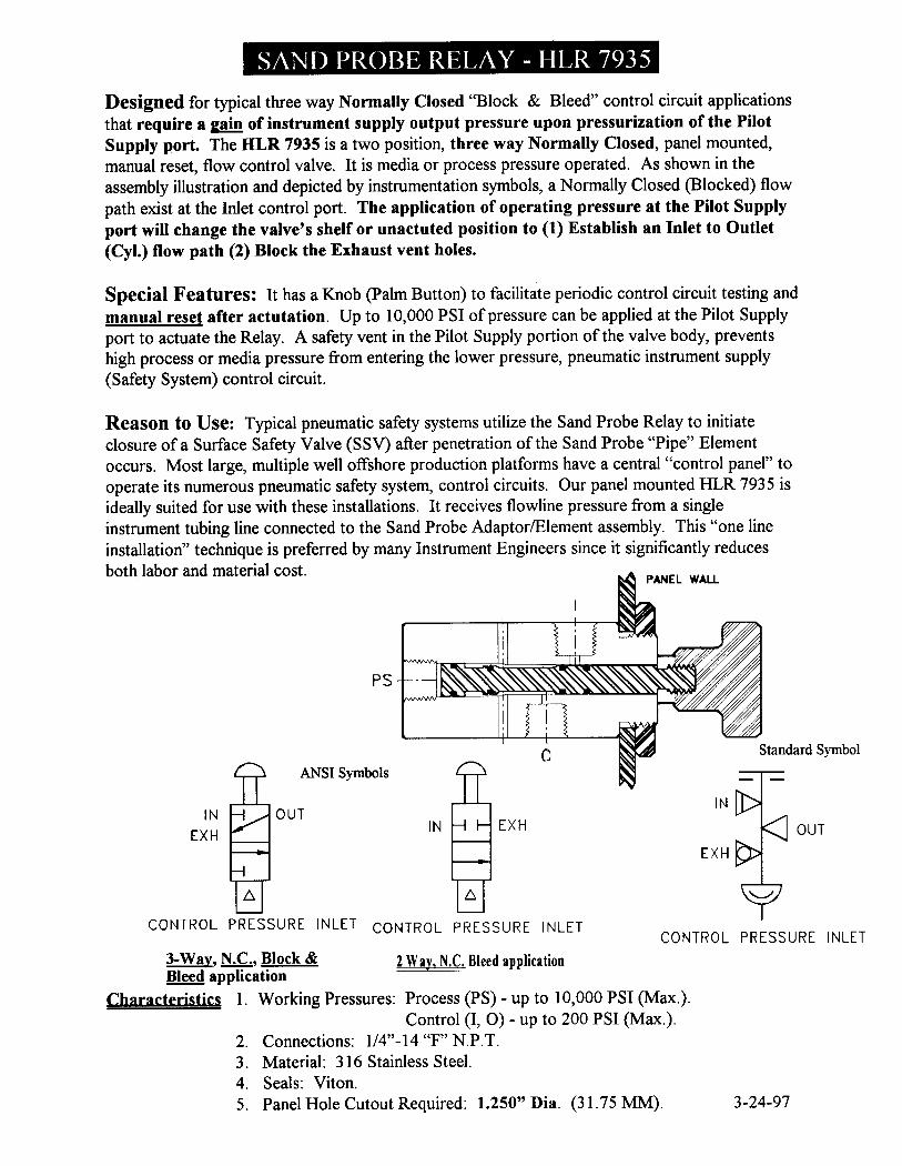
(SPECIAL – RED KNOB)
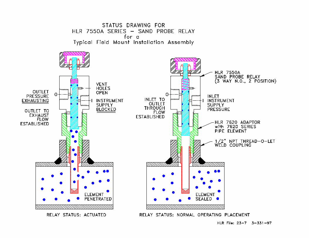
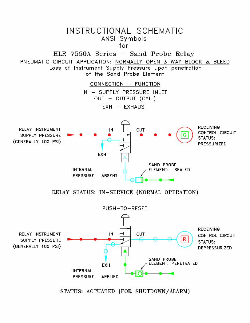
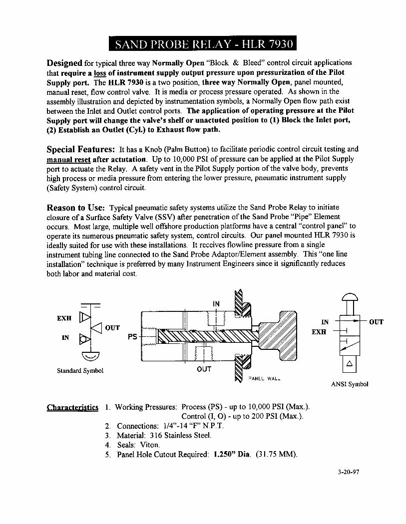
Designed for typical three way Normally Open “Block & Bleed” control circuit applicationsthat require a loss of instrument supply output pressure upon pressurization of the PilotSupply port. The HLR 7930R is a two position, three way Normally Open, panel mounted,manual reset, flow control valve. It is media or process pressure operated. As shown in theassembly illustration and depicted by instrumentation symbols, a Normally Open flow path existbetween the Inlet and Outlet control ports. The application of operating pressure at the PilotSupply port will change the valve’s shelf or unactuted position to (1) Block the Inlet port,(2) Establish an Outlet (Cyl.) to Exhaust flow path.
Special Features: It has a Red Knob (Palm Button) to facilitate periodic control circuittesting and manual reset after actutation. Up to 10,000 PSI of pressure can be applied at thePilot Supply port to actuate the Relay. A safety vent in the Pilot Supply portion of the valvebody, prevents high process or media pressure from entering the lower pressure, pneumaticinstrument supply (Safety System) control circuit.
Reason to Use: Typical pneumatic safety systems utilize the Sand Probe Relay to initiateclosure of a Surface Safety Valve (SSV) after penetration of the Sand Probe “Pipe” Elementoccurs. Most large, multiple well offshore production platforms have a central “control panel” tooperate its numerous pneumatic safety system, control circuits. Our panel mounted HLR 7930Ris ideally suited for use with these installations. It receives flowline pressure from a singleinstrument tubing line connected to the Sand Probe Adaptor/Element assembly. This “one lineinstallation” technique is preferred by many Instrument Engineers since it significantly reducesboth labor and material cost.
Characteristics 1. Working Pressures: Process (PS) - up to 10,000 PSI (Max.). Control (I, O) - up to 200 PSI (Max.).
2. Connections: 1/4”-14 “F” N.P.T.3. Material: 316 Stainless Steel.4. Seals: Viton.5. Panel Hole Cutout Required: 1.250” Dia. (31.75 MM).
12-9-97
SAND PROBE RELAY - HLR 7930R
OUTIN
Standard Symbol
ANSI Symbol
OUTIN
EXHEXH
EXH
HLR 7620 SeriesSand Probe “Pipe” Element
Model Number Selection Chart
The HLR 7620 Series Pipe Element is one component of a typical three pieceSand Probe companion assembly. It is selected whenever all of the followingprocess conditions exists:
1. The process temperature is below 140o F. (60o C.) 2. The Pipe Element is subjected to pressure below 5,000 PSI.3. A velocity below 40 feet per second exist in the flowline pipe segment.
Selecting the proper Sand Probe Pipe Element Model Number
Model Number Pipe Size Determine the designation byselecting the basic Model Number
HLR 7620-2-*** 2" (2.375" O.D.) and its corresponding Flowline
HLR 7620-3-___ 3" (3.500" O.D.) Pipe Size, as shown on left.
HLR 7620-4-___ 4" (4.500" O.D.)HLR 7620-6-___ 6" (6.625" O.D.)
Operating *** Wall Thickness Next, add the three digit Wall
Pressure Thickness (***) number to
400 - 1,000 PSI .025" complete the designation.
1,000 - 2,160 PSI .035" 2,160 - 5,000 PSI .050"
Example Model Number: HLR 7620-2-025 for a 2" Flowline installation, with a.025" Wall Thickness (required for use in a 750 PSI operating pressure, system).
HLR 7620 Series Sand Probe Pipe Element
4-23-98
1/4"-18 MNPT
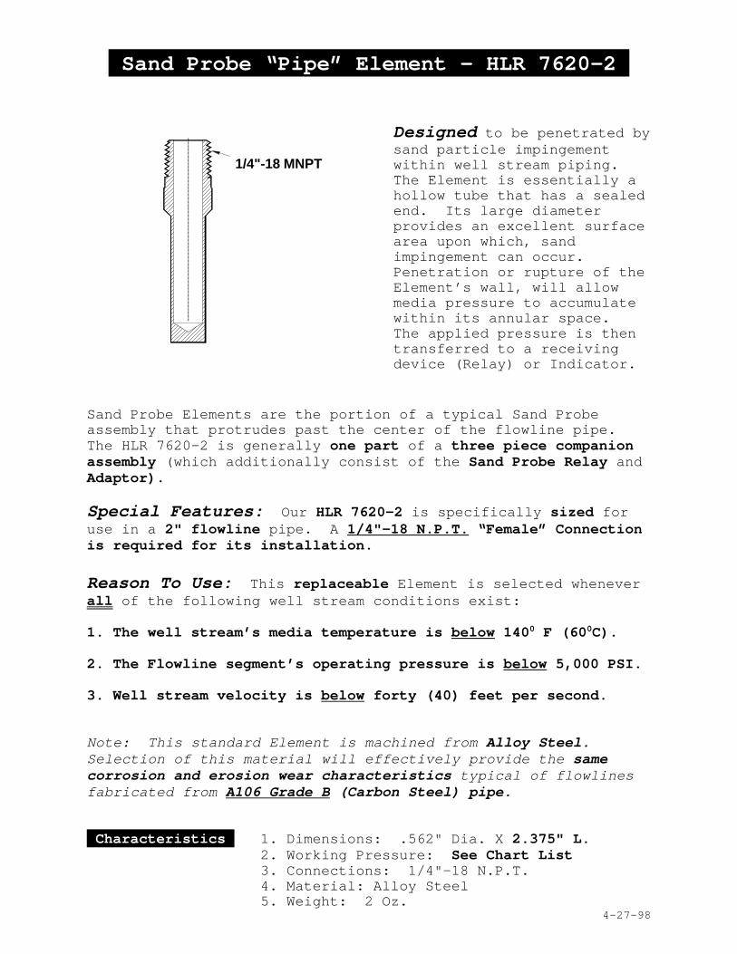
Sand Probe “Pipe” Element - HLR 7620-2
Designed to be penetrated bysand particle impingementwithin well stream piping. The Element is essentially ahollow tube that has a sealedend. Its large diameterprovides an excellent surfacearea upon which, sandimpingement can occur. Penetration or rupture of theElement’s wall, will allowmedia pressure to accumulatewithin its annular space. The applied pressure is thentransferred to a receivingdevice (Relay) or Indicator.
Sand Probe Elements are the portion of a typical Sand Probeassembly that protrudes past the center of the flowline pipe. The HLR 7620-2 is generally one part of a three piece companionassembly (which additionally consist of the Sand Probe Relay andAdaptor).
Special Features: Our HLR 7620-2 is specifically sized foruse in a 2" flowline pipe. A 1/4"-18 N.P.T. “Female” Connectionis required for its installation.
Reason To Use: This replaceable Element is selected wheneverall of the following well stream conditions exist:
1. The well stream’s media temperature is below 1400 F (600C).
2. The Flowline segment’s operating pressure is below 5,000 PSI.
3. Well stream velocity is below forty (40) feet per second.
Note: This standard Element is machined from Alloy Steel.Selection of this material will effectively provide the samecorrosion and erosion wear characteristics typical of flowlines fabricated from A106 Grade B (Carbon Steel) pipe.
Characteristics 1. Dimensions: .562" Dia. X 2.375" L.2. Working Pressure: See Chart List 3. Connections: 1/4"-18 N.P.T.4. Material: Alloy Steel5. Weight: 2 Oz.
4-27-98
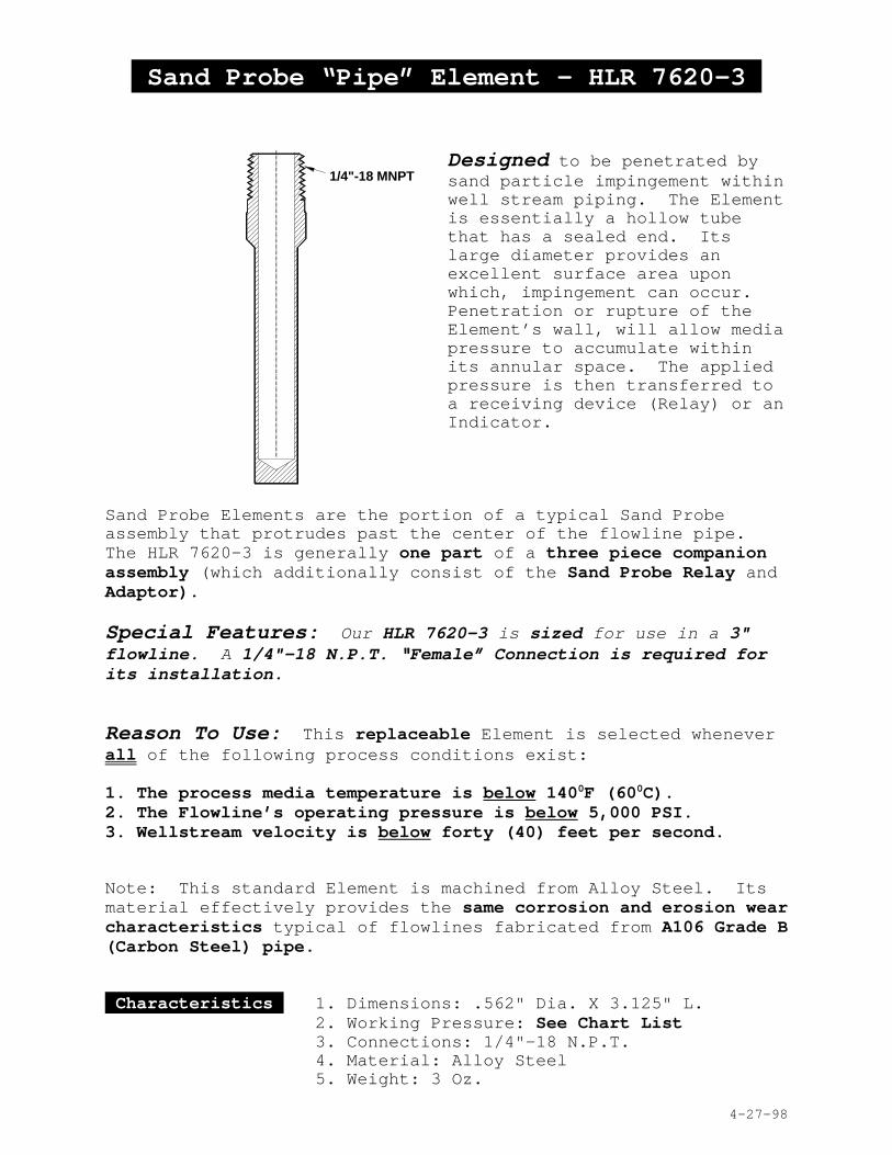
1/4"-18 MNPT
Sand Probe “Pipe” Element - HLR 7620-3
Designed to be penetrated bysand particle impingement withinwell stream piping. The Elementis essentially a hollow tubethat has a sealed end. Itslarge diameter provides anexcellent surface area uponwhich, impingement can occur. Penetration or rupture of theElement’s wall, will allow mediapressure to accumulate withinits annular space. The appliedpressure is then transferred toa receiving device (Relay) or anIndicator.
Sand Probe Elements are the portion of a typical Sand Probeassembly that protrudes past the center of the flowline pipe. The HLR 7620-3 is generally one part of a three piece companionassembly (which additionally consist of the Sand Probe Relay andAdaptor).
Special Features: Our HLR 7620-3 is sized for use in a 3"flowline. A 1/4"-18 N.P.T. “Female” Connection is required forits installation.
Reason To Use: This replaceable Element is selected wheneverall of the following process conditions exist:
1. The process media temperature is below 1400F (600C).2. The Flowline’s operating pressure is below 5,000 PSI.3. Wellstream velocity is below forty (40) feet per second.
Note: This standard Element is machined from Alloy Steel. Itsmaterial effectively provides the same corrosion and erosion wearcharacteristics typical of flowlines fabricated from A106 Grade B(Carbon Steel) pipe.
Characteristics 1. Dimensions: .562" Dia. X 3.125" L.2. Working Pressure: See Chart List 3. Connections: 1/4"-18 N.P.T.4. Material: Alloy Steel5. Weight: 3 Oz.
4-27-98
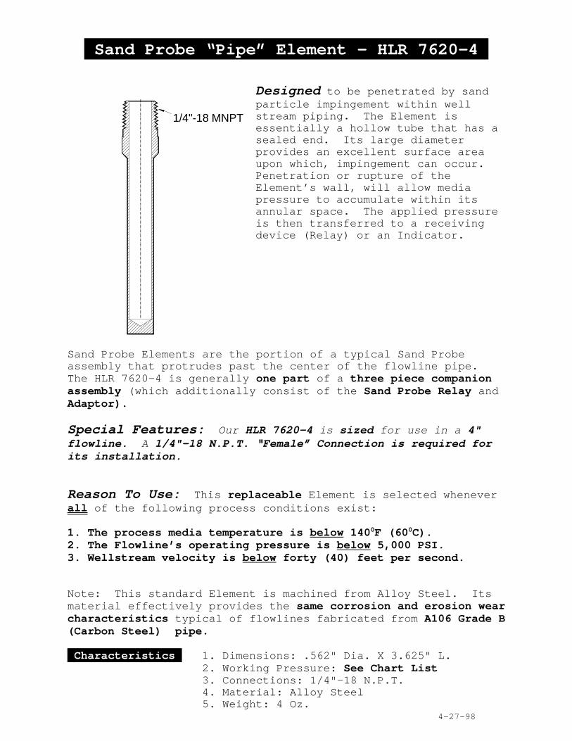
1/4"-18 MNPT
Sand Probe “Pipe” Element - HLR 7620-4
Designed to be penetrated by sandparticle impingement within wellstream piping. The Element isessentially a hollow tube that has asealed end. Its large diameterprovides an excellent surface areaupon which, impingement can occur. Penetration or rupture of theElement’s wall, will allow mediapressure to accumulate within itsannular space. The applied pressureis then transferred to a receivingdevice (Relay) or an Indicator.
Sand Probe Elements are the portion of a typical Sand Probeassembly that protrudes past the center of the flowline pipe. The HLR 7620-4 is generally one part of a three piece companionassembly (which additionally consist of the Sand Probe Relay andAdaptor).
Special Features: Our HLR 7620-4 is sized for use in a 4"flowline. A 1/4"-18 N.P.T. “Female” Connection is required forits installation.
Reason To Use: This replaceable Element is selected wheneverall of the following process conditions exist:
1. The process media temperature is below 1400F (600C).2. The Flowline’s operating pressure is below 5,000 PSI.3. Wellstream velocity is below forty (40) feet per second.
Note: This standard Element is machined from Alloy Steel. Itsmaterial effectively provides the same corrosion and erosion wearcharacteristics typical of flowlines fabricated from A106 Grade B(Carbon Steel) pipe.
Characteristics 1. Dimensions: .562" Dia. X 3.625" L.2. Working Pressure: See Chart List 3. Connections: 1/4"-18 N.P.T.4. Material: Alloy Steel5. Weight: 4 Oz.
4-27-98
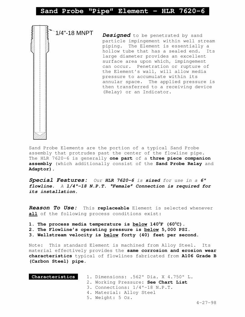
1/4"-18 MNPT
Sand Probe “Pipe” Element - HLR 7620-6
Designed to be penetrated by sandparticle impingement within well streampiping. The Element is essentially ahollow tube that has a sealed end. Itslarge diameter provides an excellentsurface area upon which, impingementcan occur. Penetration or rupture ofthe Element’s wall, will allow mediapressure to accumulate within itsannular space. The applied pressure isthen transferred to a receiving device(Relay) or an Indicator.
Sand Probe Elements are the portion of a typical Sand Probeassembly that protrudes past the center of the flowline pipe. The HLR 7620-6 is generally one part of a three piece companionassembly (which additionally consist of the Sand Probe Relay andAdaptor).
Special Features: Our HLR 7620-6 is sized for use in a 6"flowline. A 1/4"-18 N.P.T. “Female” Connection is required forits installation.
Reason To Use: This replaceable Element is selected wheneverall of the following process conditions exist:
1. The process media temperature is below 1400F (600C).2. The Flowline’s operating pressure is below 5,000 PSI.3. Wellstream velocity is below forty (40) feet per second.
Note: This standard Element is machined from Alloy Steel. Itsmaterial effectively provides the same corrosion and erosion wearcharacteristics typical of flowlines fabricated from A106 Grade B(Carbon Steel) pipe.
Characteristics 1. Dimensions: .562" Dia. X 4.750" L.2. Working Pressure: See Chart List 3. Connections: 1/4"-18 N.P.T.4. Material: Alloy Steel5. Weight: 5 Oz.
4-27-98
HLR 7620 “MR” SeriesSand Probe Adaptor/Element
Model Number Selection Chart
The HLR 7620 “MR” Series is one part of a two piece Sand Probecompanion assembly. It is selected whenever any of the following processconditions exists:
1. The process temperature is above 140o F. (60o C.) 2. The Adaptor/Element may be subjected to pressure above 5,000 PSI.3. A velocity above 40 feet per second exist in the flowline pipe segment.
Selecting the proper Adaptor/Element Model Number
Model Number Pipe Size Determine the designation byselecting the basic Model Number
HLR 7620MR2-*** 2" (2.375" O.D.) and its corresponding FlowlineHLR 7620MR3-___ 3" (3.500" O.D.) Pipe Size, as shown on left.HLR 7620MR4-___ 4" (4.500" O.D.)HLR 7620MR6-___ 6" (6.625" O.D.)
Operating *** Wall Thickness Next, add the three digit Wall Pressure Thickness (***) number to 400 - 1,000 PSI .025" complete the designation.
1,000 - 2,160 PSI .035" 2,160 - 5,000 PSI .050" 5,000 - 10, 000 PSI .065"
Example Model Number: HLR 7620MR2-025 for a 2" Flowline installation, with a.025" Wall Thickness (required for use in a 750 PSI operating pressure, system).
HLR 7620 “MR”Series
Sand ProbeAdaptor/Element
4-23-98
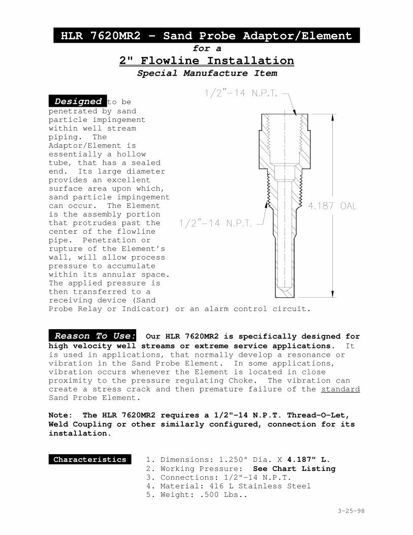
HLR 7620MR2 - Sand Probe Adaptor/Element for a
2" Flowline InstallationSpecial Manufacture Item
Designed to bepenetrated by sandparticle impingementwithin well streampiping. TheAdaptor/Element isessentially a hollowtube, that has a sealedend. Its large diameterprovides an excellentsurface area upon which,sand particle impingementcan occur. The Elementis the assembly portionthat protrudes past thecenter of the flowlinepipe. Penetration orrupture of the Element’swall, will allow processpressure to accumulatewithin its annular space. The applied pressure isthen transferred to areceiving device (SandProbe Relay or Indicator) or an alarm control circuit.
Reason To Use: Our HLR 7620MR2 is specifically designed forhigh velocity well streams or extreme service applications. Itis used in applications, that normally develop a resonance orvibration in the Sand Probe Element. In some applications,vibration occurs whenever the Element is located in closeproximity to the pressure regulating Choke. The vibration cancreate a stress crack and then premature failure of the standardSand Probe Element.
Note: The HLR 7620MR2 requires a 1/2"-14 N.P.T. Thread-O-Let,Weld Coupling or other similarly configured, connection for itsinstallation.
Characteristics 1. Dimensions: 1.250" Dia. X 4.187" L.2. Working Pressure: See Chart Listing 3. Connections: 1/2"-14 N.P.T.4. Material: 416 L Stainless Steel5. Weight: .500 Lbs..
3-25-98
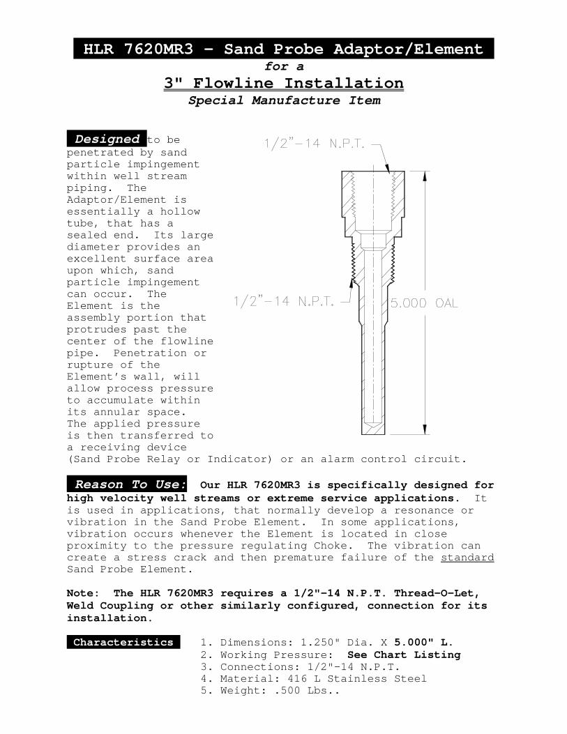
HLR 7620MR3 - Sand Probe Adaptor/Element for a
3" Flowline InstallationSpecial Manufacture Item
Designed to bepenetrated by sandparticle impingementwithin well streampiping. TheAdaptor/Element isessentially a hollowtube, that has asealed end. Its largediameter provides anexcellent surface areaupon which, sandparticle impingementcan occur. TheElement is theassembly portion thatprotrudes past thecenter of the flowlinepipe. Penetration orrupture of theElement’s wall, willallow process pressureto accumulate withinits annular space. The applied pressureis then transferred toa receiving device(Sand Probe Relay or Indicator) or an alarm control circuit.
Reason To Use: Our HLR 7620MR3 is specifically designed forhigh velocity well streams or extreme service applications. Itis used in applications, that normally develop a resonance orvibration in the Sand Probe Element. In some applications,vibration occurs whenever the Element is located in closeproximity to the pressure regulating Choke. The vibration cancreate a stress crack and then premature failure of the standardSand Probe Element.
Note: The HLR 7620MR3 requires a 1/2"-14 N.P.T. Thread-O-Let,Weld Coupling or other similarly configured, connection for itsinstallation.
Characteristics 1. Dimensions: 1.250" Dia. X 5.000" L.2. Working Pressure: See Chart Listing 3. Connections: 1/2"-14 N.P.T.4. Material: 416 L Stainless Steel5. Weight: .500 Lbs..
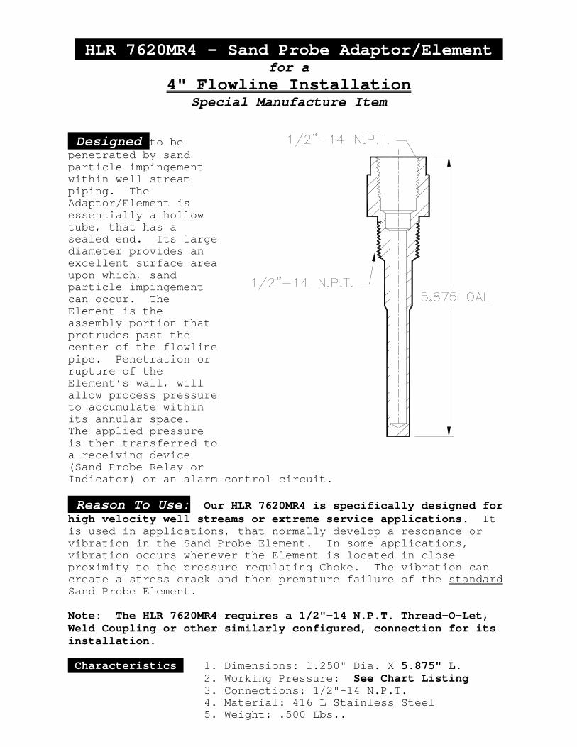
HLR 7620MR4 - Sand Probe Adaptor/Element for a
4" Flowline InstallationSpecial Manufacture Item
Designed to bepenetrated by sandparticle impingementwithin well streampiping. TheAdaptor/Element isessentially a hollowtube, that has asealed end. Its largediameter provides anexcellent surface areaupon which, sandparticle impingementcan occur. TheElement is theassembly portion thatprotrudes past thecenter of the flowlinepipe. Penetration orrupture of theElement’s wall, willallow process pressureto accumulate withinits annular space. The applied pressureis then transferred toa receiving device(Sand Probe Relay orIndicator) or an alarm control circuit.
Reason To Use: Our HLR 7620MR4 is specifically designed forhigh velocity well streams or extreme service applications. Itis used in applications, that normally develop a resonance orvibration in the Sand Probe Element. In some applications,vibration occurs whenever the Element is located in closeproximity to the pressure regulating Choke. The vibration cancreate a stress crack and then premature failure of the standardSand Probe Element.
Note: The HLR 7620MR4 requires a 1/2"-14 N.P.T. Thread-O-Let,Weld Coupling or other similarly configured, connection for itsinstallation.
Characteristics 1. Dimensions: 1.250" Dia. X 5.875" L.2. Working Pressure: See Chart Listing 3. Connections: 1/2"-14 N.P.T.4. Material: 416 L Stainless Steel5. Weight: .500 Lbs..

HLR 7620MR6 - Sand Probe Adaptor/Element for a
6" Flowline InstallationSpecial Manufacture Item
Designed to bepenetrated by sandparticle impingementwithin well streampiping. TheAdaptor/Element isessentially a hollowtube, that has asealed end. Its largediameter provides anexcellent surface areaupon which, sandparticle impingementcan occur. TheElement is theassembly portion thatprotrudes past thecenter of the flowlinepipe. Penetration orrupture of theElement’s wall, willallow process pressureto accumulate withinits annular space. The applied pressureis then transferred toa receiving device(Sand Probe Relay orIndicator) or an alarm control circuit.
Reason To Use: Our HLR 7620MR6 is specifically designed forhigh velocity well streams or extreme service applications. Itis used in applications, that normally develop a resonance orvibration in the Sand Probe Element. In some applications,vibration occurs whenever the Element is located in closeproximity to the pressure regulating Choke. The vibration cancreate a stress crack and then premature failure of the standardSand Probe Element.
Note: The HLR 7620MR6 requires a 1/2"-14 N.P.T. Thread-O-Let,Weld Coupling or other similarly configured, connection for itsinstallation.
Characteristics 1. Dimensions: 1.250" Dia. X 6.625" L.2. Working Pressure: See Chart Listing 3. Connections: 1/2"-14 N.P.T.4. Material: 416 L Stainless Steel5. Weight: .500 Lbs..
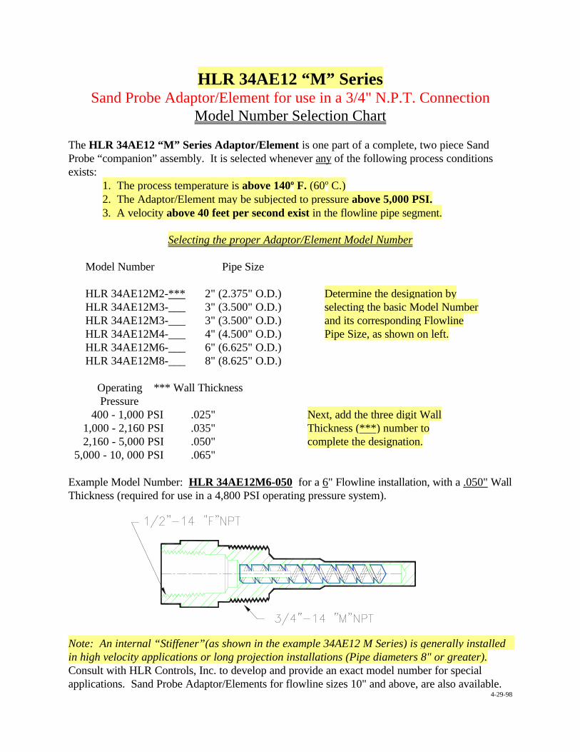
HLR 34AE12 “M” SeriesSand Probe Adaptor/Element for use in a 3/4" N.P.T. Connection
Model Number Selection Chart
The HLR 34AE12 “M” Series Adaptor/Element is one part of a complete, two piece SandProbe “companion” assembly. It is selected whenever any of the following process conditionsexists:
1. The process temperature is above 140o F. (60o C.) 2. The Adaptor/Element may be subjected to pressure above 5,000 PSI.3. A velocity above 40 feet per second exist in the flowline pipe segment.
Selecting the proper Adaptor/Element Model Number
Model Number Pipe Size
HLR 34AE12M2-*** 2" (2.375" O.D.) Determine the designation byHLR 34AE12M3-___ 3" (3.500" O.D.) selecting the basic Model NumberHLR 34AE12M3-___ 3" (3.500" O.D.) and its corresponding FlowlineHLR 34AE12M4-___ 4" (4.500" O.D.) Pipe Size, as shown on left.HLR 34AE12M6-___ 6" (6.625" O.D.)HLR 34AE12M8-___ 8" (8.625" O.D.)
Operating *** Wall Thickness Pressure 400 - 1,000 PSI .025" Next, add the three digit Wall
1,000 - 2,160 PSI .035" Thickness (***) number to 2,160 - 5,000 PSI .050" complete the designation. 5,000 - 10, 000 PSI .065"
Example Model Number: HLR 34AE12M6-050 for a 6" Flowline installation, with a .050" WallThickness (required for use in a 4,800 PSI operating pressure system).
Note: An internal “Stiffener”(as shown in the example 34AE12 M Series) is generally installed in high velocity applications or long projection installations (Pipe diameters 8" or greater).Consult with HLR Controls, Inc. to develop and provide an exact model number for specialapplications. Sand Probe Adaptor/Elements for flowline sizes 10" and above, are also available.
4-29-98
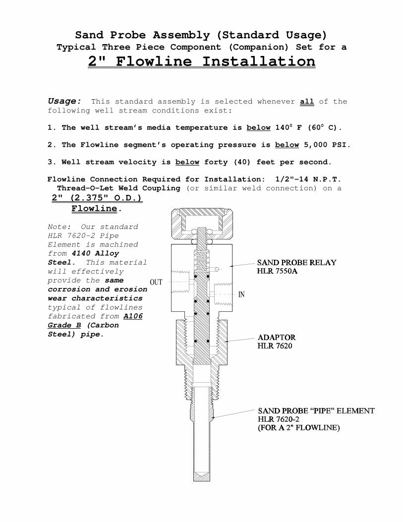
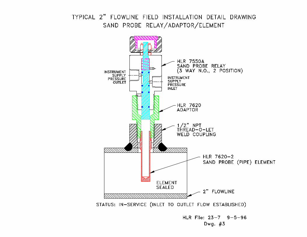
Sand Probe Assembly (Standard Usage)Typical Three Piece Component (Companion) Set for a
2" Flowline Installation
Usage: This standard assembly is selected whenever all of thefollowing well stream conditions exist:
1. The well stream’s media temperature is below 1400 F (600 C).
2. The Flowline segment’s operating pressure is below 5,000 PSI.
3. Well stream velocity is below forty (40) feet per second.
Flowline Connection Required for Installation: 1/2"-14 N.P.T. Thread-O-Let Weld Coupling (or similar weld connection) on a 2" (2.375" O.D.)
Flowline.
Note: Our standardHLR 7620-2 PipeElement is machinedfrom 4140 AlloySteel. This materialwill effectivelyprovide the samecorrosion and erosionwear characteristicstypical of flowlines fabricated from A106Grade B (CarbonSteel) pipe.
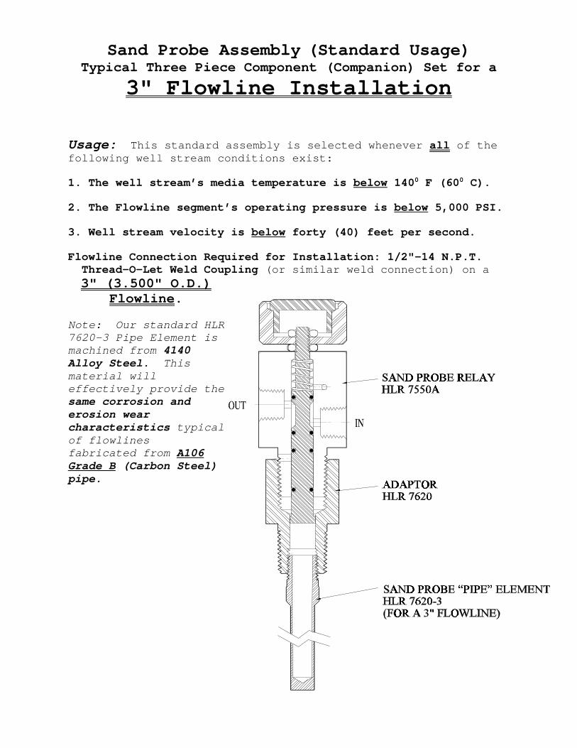
Sand Probe Assembly (Standard Usage)Typical Three Piece Component (Companion) Set for a
3" Flowline Installation
Usage: This standard assembly is selected whenever all of thefollowing well stream conditions exist:
1. The well stream’s media temperature is below 1400 F (600 C).
2. The Flowline segment’s operating pressure is below 5,000 PSI.
3. Well stream velocity is below forty (40) feet per second.
Flowline Connection Required for Installation: 1/2"-14 N.P.T. Thread-O-Let Weld Coupling (or similar weld connection) on a 3" (3.500" O.D.)
Flowline.
Note: Our standard HLR7620-3 Pipe Element ismachined from 4140Alloy Steel. Thismaterial willeffectively provide thesame corrosion anderosion wearcharacteristics typicalof flowlines fabricated from A106Grade B (Carbon Steel)pipe.
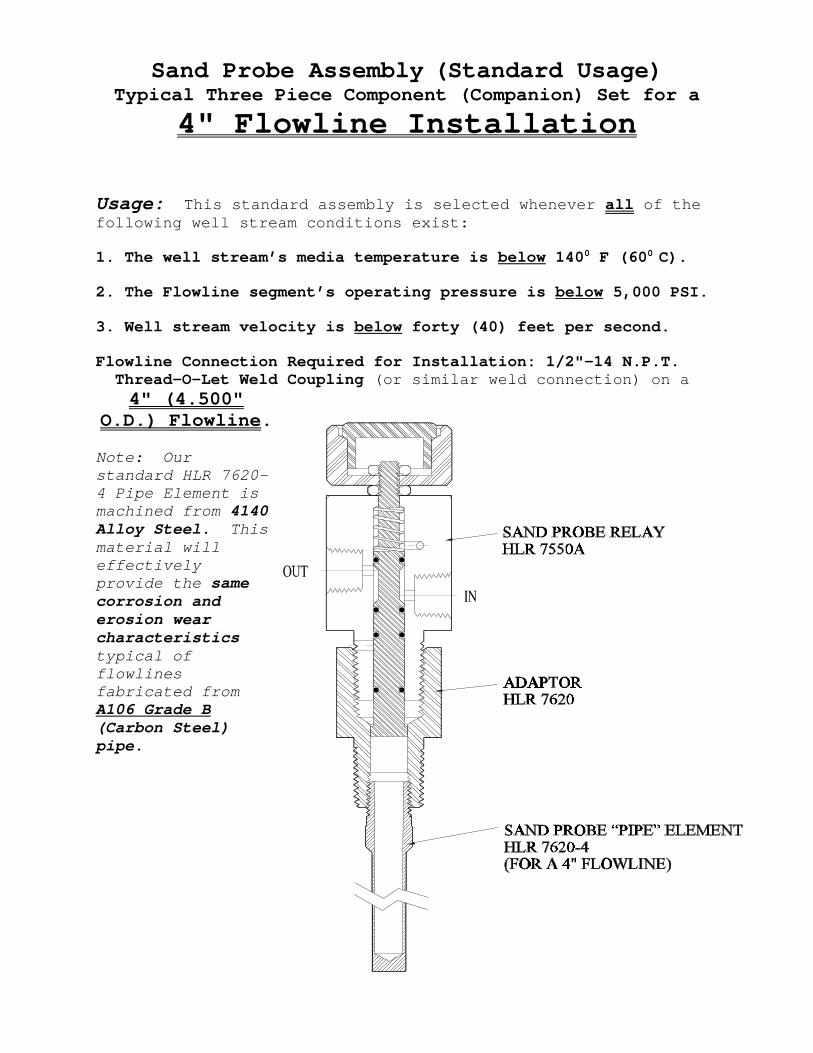
Sand Probe Assembly (Standard Usage)Typical Three Piece Component (Companion) Set for a
4" Flowline Installation
Usage: This standard assembly is selected whenever all of thefollowing well stream conditions exist:
1. The well stream’s media temperature is below 1400 F (600 C).
2. The Flowline segment’s operating pressure is below 5,000 PSI.
3. Well stream velocity is below forty (40) feet per second.
Flowline Connection Required for Installation: 1/2"-14 N.P.T. Thread-O-Let Weld Coupling (or similar weld connection) on a
4" (4.500"O.D.) Flowline.
Note: Ourstandard HLR 7620-4 Pipe Element ismachined from 4140Alloy Steel. Thismaterial willeffectivelyprovide the samecorrosion anderosion wearcharacteristicstypical offlowlines fabricated fromA106 Grade B(Carbon Steel)pipe.
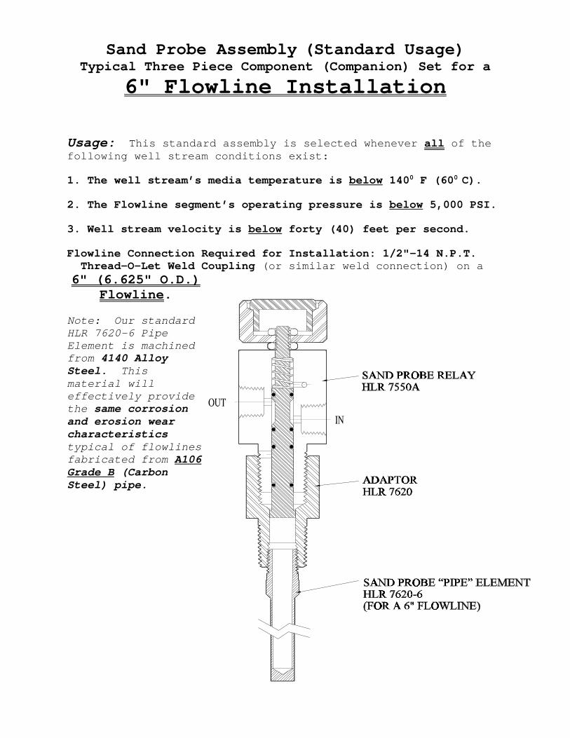
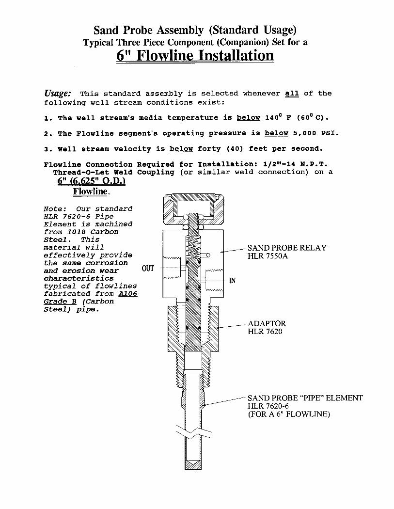
Sand Probe Assembly (Standard Usage)Typical Three Piece Component (Companion) Set for a
6" Flowline Installation
Usage: This standard assembly is selected whenever all of thefollowing well stream conditions exist:
1. The well stream’s media temperature is below 1400 F (600 C).
2. The Flowline segment’s operating pressure is below 5,000 PSI.
3. Well stream velocity is below forty (40) feet per second.
Flowline Connection Required for Installation: 1/2"-14 N.P.T. Thread-O-Let Weld Coupling (or similar weld connection) on a 6" (6.625" O.D.)
Flowline.
Note: Our standardHLR 7620-6 PipeElement is machinedfrom 4140 AlloySteel. Thismaterial willeffectively providethe same corrosionand erosion wearcharacteristicstypical of flowlines fabricated from A106Grade B (CarbonSteel) pipe.