Sampling and Analysis Plan Waste Treatment Plant … Treatment Plant Seismic Boreholes Project ......
21
PNNL-15848 Rev. 0 Sampling and Analysis Plan Waste Treatment Plant Seismic Boreholes Project May 2006 Prepared for the U.S. Department of Energy under Contract DE-AC05-76RL01830
Transcript of Sampling and Analysis Plan Waste Treatment Plant … Treatment Plant Seismic Boreholes Project ......

PNNL-15848 Rev. 0
Sampling and Analysis Plan Waste Treatment Plant Seismic Boreholes Project May 2006 Prepared for the U.S. Department of Energy under Contract DE-AC05-76RL01830

DISCLAIMER This report was prepared as an account of work sponsored by an agency of the United States Government. Neither the United States Government nor any agency thereof, nor Battelle Memorial Institute, nor any of their employees, makes any warranty, express or implied, or assumes any legal liability or responsibility for the accuracy, completeness, or usefulness of any information, apparatus, product, or process disclosed, or represents that its use would not infringe privately owned rights. Reference herein to any specific commercial product, process, or service by trade name, trademark, manufacturer, or otherwise does not necessarily constitute or imply its endorsement, recommendation, or favoring by the United States Government or any agency thereof, or Battelle Memorial Institute. The views and opinions of authors expressed herein do not necessarily state or reflect those of the United States Government or any agency thereof.
PACIFIC NORTHWEST NATIONAL LABORATORY operated by BATTELLE
for the UNITED STATES DEPARTMENT OF ENERGY
under Contract DE-AC05-76RL01830
Printed in the United States of America
Available to DOE and DOE contractors from the Office of Scientific and Technical Information,
P.O. Box 62, Oak Ridge, TN 37831-0062; ph: (865) 576-8401 fax: (865) 576-5728
email: [email protected]
Available to the public from the National Technical Information Service, U.S. Department of Commerce, 5285 Port Royal Rd., Springfield, VA 22161
ph: (800) 553-6847 fax: (703) 605-6900
email: [email protected] online ordering: http://www.ntis.gov/ordering.htm
This document was printed on recycled paper. (8/00)
PNNL-15848 Rev. 0
Sampling and Analysis Plan Waste Treatment Plant Seismic Boreholes Project May 2006 Prepared for the Office of River Protection U.S. Department of Energy under Contract DE-AC05-76RL01830 Pacific Northwest National Laboratory Richland, Washington 99352
iii
Abstract
This sampling and analysis plan (SAP) describes planned data collection activities for four entry boreholes through the sediment overlying the basalt, up to three new deep rotary boreholes through the basalt and sedimentary interbeds, and one corehole through the basalt and sedimentary interbeds at the Waste Treatment Plant (WTP) site. The SAP will be used in concert with the quality assurance plan for the project to guide the procedure development and data collection activities needed to support borehole drilling, geophysical measurements, and sampling. This SAP identifies the American Society of Testing Materials standards, Hanford Site procedures, and other guidance to be followed for data collection activities.
v
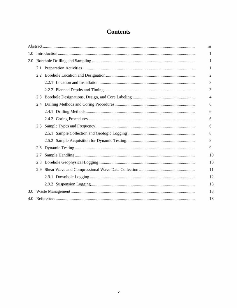
Contents
Abstract .............................................................................................................................................. iii
1.0 Introduction................................................................................................................................ 1 2.0 Borehole Drilling and Sampling ................................................................................................ 1 2.1 Preparation Activities ......................................................................................................... 1 2.2 Borehole Location and Designation ................................................................................... 2 2.2.1 Location and Installation ......................................................................................... 3 2.2.2 Planned Depths and Timing..................................................................................... 3 2.3 Borehole Designations, Design, and Core Labeling .......................................................... 4 2.4 Drilling Methods and Coring Procedures........................................................................... 6 2.4.1 Drilling Methods...................................................................................................... 6 2.4.2 Coring Procedures.................................................................................................... 6 2.5 Sample Types and Frequency............................................................................................. 6 2.5.1 Sample Collection and Geologic Logging............................................................... 8 2.5.2 Sample Acquisition for Dynamic Testing................................................................ 8 2.6 Dynamic Testing ................................................................................................................ 9 2.7 Sample Handling ................................................................................................................ 10 2.8 Borehole Geophysical Logging.......................................................................................... 10 2.9 Shear Wave and Compressional Wave Data Collection .................................................... 11 2.9.1 Downhole Logging .................................................................................................. 12 2.9.2 Suspension Logging................................................................................................. 13 3.0 Waste Management.................................................................................................................... 13 4.0 References .................................................................................................................................. 13

vi
Figures
1 Location of WTP Boreholes....................................................................................................... 2
2 Proposed Design for Mud-Rotary WTP Boreholes.................................................................... 5
Tables
1 Basalt Members and Sedimentary Interbeds Expected at the WTP Borehole Sites................... 4
2 Approximate Coordinates of WTP Boreholes ........................................................................... 5
3 Selected Intervals for Suprabasalt Coring.................................................................................. 7
4 USACE Review Panel-Recommended Number of Resonant Column/Torsional Shear Testing Samples ......................................................................................................................... 9

1
1.0 Introduction
This sampling and analysis plan (SAP) describes planned data collection activities for four entry boreholes through the sediment overlying the basalt, up to three new deep rotary boreholes through the basalt and sedimentary interbeds, and one corehole through the basalt and sedimentary interbeds at the Waste Treatment Plant (WTP) site. The SAP and Quality Assurance Project Plan (QAPjP 2006) will be used to guide the procedure development and data collection activities needed to support borehole drilling, geophysical measurements, and sampling. This SAP identifies standards (e.g., American Society of Testing Materials [ASTM]), Hanford Site procedures, and other guidance documents for data collection activities. Procedures not yet available or contractor-specific procedures will be submitted for review and acceptance prior to commencement of work on the site. All data collection activities will be governed by activity-specific procedures reviewed and accepted by the project consistent with PNWD (2005), QAPjP (2006), and DOE O 414.1C (2005). Only approved procedures will be used for this work.
2.0 Borehole Drilling and Sampling
The tasks involved in this sampling and analysis plan include
• preparation activities • borehole location and designation • drilling and geologic material sampling • borehole geophysical logging • shearwave and compressional wave data collection • sample handling • sample analysis • documentation.
2.1 Preparation Activities
Preparation activities necessary before beginning fieldwork for borehole drilling and data collection include
• coordinating with team members • coordinating with support services as addressed in the Quality Assurance Project Plan (QAPjP 2006) • evaluating drilling techniques • obtaining support documentation • obtaining monitoring and sampling equipment • ensuring that all required training has been completed.

2
2.2 Borehole Location and Designation
The locations for the boreholes planned for this study are shown in Figure 1. The cored borehole (C4998) is located at the site for C4997. Boreholes C4993 will be used, should insufficient data be obtained from C4997. Boreholes C4994 and C4995 are optional or backup borehole locations that will not be used unless they are deemed necessary at a future time.
Figure 1. Location of WTP Boreholes (adapted from Gardner et al. 2006).

3
Initially, four entry boreholes from the surface to the top of the basalt will be drilled. These will provide access for three deep boreholes in the basalt and one corehole through the basalt. The three deep boreholes are designed primarily to provide access to the subsurface for geophysical measurement. The corehole is designed to provide a continuous record of the rock that will be penetrated by the three deep rotary boreholes. The boreholes are designed to also provide samples to 1) identify the geologic units below the WTP site, 2) characterize the sediments and basalt below the WTP, 3) provide core samples for dynamic laboratory testing, and 4) obtain geophysical data including shear wave (Vs) and compressional wave (Vp) data and downhole geophysical logging. The boreholes also will provide groundwater samples for other Hanford projects if they desire, but those projects will be responsible for their sampling and analysis requirements and quality assurance procedures; thus, groundwater sampling is not addressed further in this plan. All borings will be constructed in accordance with Washington Administrative Code (WAC) 173-160 requirements and other applicable Hanford requirements.
2.2.1 Location and Installation
The primary factor dictating the location of the boreholes is the need to acquire Vp and Vs data for the WTP site. The number of boreholes and their locations to be used in this study have been determined as a result of discussions among the team members, the U.S. Army Corps of Engineers and its contractors (referred to here as the USACE Review Panel), and the Defense Nuclear Facilities Safety Board (DNFSB).
Rationale. Major objectives of the proposed geophysical surveys in the planned deep boreholes are to obtain reliable and unambiguous data on velocity (most importantly Vs but also Vp), lithology, and thickness of the interbeds in the Saddle Mountains Basalt and to obtain sediment core from the Hanford formation and Ringold Formation for dynamic testing. The USACE Review Panel has indicated that previous site response analysis suggested overburden gravels had a more linear (sand-like) response than gravels in other testing programs. The sampling and dynamic testing are proposed to more accurately determine the nonlinear response of the Hanford gravels and Ringold Formation because this might influence predicted low-period ground surface spectral accelerations.
The primary borehole (C4997) and accompanying corehole (C4998) are located to allow collection of P-wave and S-wave velocity data near the Pretreatment Facility (PTF) and High-Level Waste Vitrification Plant (HLW). Boreholes C4995 and C4996 are placed near the PTF and HLW facilities for additional data collection if deemed necessary by the Senior Review Group, a group appointed by the U.S. Department of Energy (DOE) to oversee the project. Borehole sites C4994 and C4995 would provide data from other parts of the WTP site; these borehole sites are currently considered backup locations and not the primary data collection sites.
2.2.2 Planned Depths and Timing
The entry boreholes will be drilled to the top of basalt. The deep mud-rotary boreholes and the wireline corehole will be drilled into the top of the Wanapum Basalt, which is approximately 1250 feet below the surface (Table 1). The stratigraphy predicted to be encountered in these boreholes is given in Table 1.

4
Table 1. Basalt Members and Sedimentary Interbeds Expected at the WTP Borehole Sites
C4996
Northwest C4995
Northeast C4997 Center
C4993 Southwest
C4994 Southeast
Surface Elevation
690 feet (topographic map)
690 feet (topographic map)
690 feet (topographic map)
670 feet (located in Gout Vault pit)
690 feet (topographic map)
Elevation of Top of Basalt
300 (±10) feet above MSL
300 (±10) feet above MSL
290 (±10) feet above MSL
285 (±10) feet above MSL
285 (±10) feet above MSL
Unit Thickness
(feet) Drilled Depth(a)
Thickness (feet)
Drilled Depth(a)
Thickness (feet)
Drilled Depth(a)
Thickness (feet)
Drilled Depth(a)
Thickness (feet)
Drilled Depth(a)
Suprabasalt Sediments
390 0 390 0 400 0 385 0 405 0
Hanford formation
250 0 250 0 260 0 245 0 260 0
Ringold Formation
140 250 140 250 140 260 140 245 145 260
Elephant Mountain Member(b,c)
100(c) ±15
390 ±15
100(c) ±15
390 ±15
100(c) ±15
400 ±15
100(c) ±15
385 ±15
100(c) ±15
405 ±15
Rattlesnake Ridge Interbed
60 ±8
490 ±8
60 ±8
490 ±8
60 ±8
500 ±8
60 ±8
485 ±8
60 ±8
505 ±8
Pomona Member(b)
185 ±10
550 ±10
185 ±10
550 ±10
185 ±10
560 ±10
185 ±10
545 ±10
185 ±10
565 ±10
Selah Interbed
22 ±5
735 ±5
22 ±5
735 ±5
22 ±5
745 ±5
22 ±5
730 ±5
22 ±5
750 ±5
Esquatzel Member(b)
100 ±10
757 ±10
100 ±10
757 ±10
100 ±10
767 ±10
100 ±10
752 ±10
100 ±10
772 ±10
Cold Creek Interbed
95 ±10
857 ±10
95 ±10
857 ±10
95 ±10
867 ±10
95 ±10
852 ±10
95 ±10
872 ±10
Umatilla Member(b,c)
150 ±10
952 ±10
150 ±10
952 ±10
150 ±10
962 ±10
150 ±10
947 ±10
150 ±10
967 ±10
Mabton Interbed
118 ±10
1102 ±10
118 ±10
1102 ±10
118 ±10
1112 ±10
118 ±10
1097 ±10
118 ±10
1117±10
Priest Rapids Member(b)
1220 ±10
1220 ±10
1230 ±10
1215 ±10
1235±10
(a) Top of unit in feet. (b) Basalt; interbed is sediment. (c) Eroded flow top; lava flow invaded water and sediment, producing pillowed flow top, so amount of erosion uncertain.
2.3 Borehole Designations, Design, and Core Labeling
Boreholes are given designations that relate to the area in which they are located. The designations used in this plan and locations in Hanford coordinates are listed in Table 2. Proposed casing as-builts are shown in Figure 2; the drilling oversight contractor (Duratek Federal Services) will determine the final design.

5
Table 2. Approximate Coordinates of WTP Boreholes
Coordinates Location Hanford ID No.
Primary Boreholes N 3,901.11 E 10,381.89 Center of site C4997 N 3,901 E 10,381 Cored hole C4998
Supplementary Boreholes N 3807.77 E 9,670.65 SW of site C4993 N 4,745.88 E 10,005.89 NW of site C4996
Backup Boreholes N 3,440.48 E 11,088.26 SE of site C4994 N 4,610.11 E 11,072.15 NE of site C4995
Figure 2. Proposed Design for Mud-Rotary WTP Boreholes (from Gardner et al. 2006)
6
2.4 Drilling Methods and Coring Procedures
2.4.1 Drilling Methods
Three types of drilling methods (suprabasalt/overburden cable tool, mud rotary, and wireline corehole), each with associated sampling, will be used. These are discussed in Gardner et al. (2006).
2.4.2 Coring Procedures
Basalt and Interbed Sediment Continuous Coring. Continuously drilled core will be taken through the basalt. This is a routine type of drilling that has been done in the past at Hanford as part of the Basalt Waste Isolation Project (BWIP). A drill rig designed for this type of coring will be used. Prior to beginning rock coring, the depth to the top of the rock surface shall be recorded. The coring shall be accomplished according to ASTM D2113-99 or equivalent standard. The exact procedure will be determined as part of the bid process. The core shall be freed from the core lifter and extruded from the barrel into a core trough in a manner that will prevent breakage and reversal of individual pieces. The trough shall be longer than the core barrel. All cores shall be arranged neatly in the partitioned boxes in the same sequence in which they occurred before removal from the hole. Facing the open box, cores shall be arranged in descending sequence beginning at the left end of the trough and continuing in the other troughs from left to right. The highest part of the core shall be placed in Box 1, and the lower portions of the core shall be placed in the other boxes in consecutive order. All drill cores will be labeled with respect to the drill site borehole and depth (beginning and ending). Core will be stored onsite for reference during drilling of the other boreholes. After it has been deemed no longer needed at the drill site, it will be transported to the Hanford Geotechnical Sample Library for permanent archival.
Suprabasalt (Overburden) Sediment Core. Core samples through the selected portions of the suprabasalt sediments also are required for dynamic testing. Recognizing that this is a difficult task but an important one, methods described in ASTM D1586-99, D1587-00, and D3550-01 or equivalent will be used that will allow collection of intact soil/sediment sample(s) (i.e., core) representative of the selected intervals. A cable tool drilling technique capable of collecting core will be used (Gardner et al. 2006).
Sediment samples obtained from the intact coring process during drilling will be sealed in liners of stainless steel or other equivalent material and follow guidance of ASTM D4220-95. Refrigeration is not required for these samples, but samples must be stored away from freezing conditions or extreme heat to protect the integrity of the core. The liners will be labeled with the borehole number and depth interval of the sample and clearly marked to indicate the sample top and bottom. After a field radiation survey, the samples will be transported to the Pacific Northwest National Laboratory (PNNL) Radiochemical Processing Laboratory (RPL). The RPL is capable of testing the samples for contamination and can release them if determined to be clean. If there are any contamination issues, the laboratory has the capability to flush samples with water to leach out tritium. This way, only certified samples that do not exceed release or testing laboratory receipt requirements would be sent offsite for dynamic testing.
2.5 Sample Types and Frequency
Three types of samples will be collected: suprabasalt (overburden) cuttings and drive samples, basalt and interbed core, and mud-rotary basalt and interbed cuttings. Core samples are addressed in Section 2.4.
7
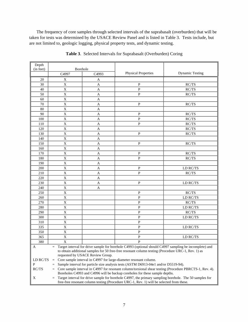
The frequency of core samples through selected intervals of the suprabasalt (overburden) that will be taken for tests was determined by the USACE Review Panel and is listed in Table 3. Tests include, but are not limited to, geologic logging, physical property tests, and dynamic testing.
Table 3. Selected Intervals for Suprabasalt (Overburden) Coring
Depth (in feet) Borehole
C4997 C4993 Physical Properties Dynamic Testing
20 X A 30 X A P RC/TS 40 X A P RC/TS 50 X A P RC/TS 60 X A 70 X A P RC/TS 80 X A 90 X A P RC/TS
100 X A P RC/TS 110 X A P RC/TS 120 X A RC/TS 130 X A P RC/TS 140 X A 150 X A P RC/TS 160 X A 170 X A P RC/TS 180 X A P RC/TS 190 X A 200 X A P LD RC/TS 210 X A P RC/TS 220 X A 230 X A P LD RC/TS 240 X A 250 X P RC/TS 260 X P LD RC/TS 270 X P RC/TS 280 X P LD RC/TS 290 X P RC/TS 300 X P LD RC/TS 310 X P 335 X P LD RC/TS 350 X P 365 X P LD RC/TS 380 X P
A = Target interval for drive sample for borehole C4993 (optional should C4997 sampling be incomplete) and to obtain additional samples for 50 free-free resonant column testing (Procedure URC-1, Rev. 1) as requested by USACE Review Group.
LD RC/TS = Core sample interval in C4997 for large-diameter resonant column. P = Sample interval for particle size analysis tests (ASTM D6913-04e1 and/or D5519-94). RC/TS = Core sample interval in C4997 for resonant column/torsional shear testing (Procedure PBRCTS-1, Rev. 4).
Boreholes C4993 and C4996 will be backup coreholes for these sample depths. X = Target interval for drive sample for borehole C4997, the primary sampling borehole. The 50 samples for
free-free resonant column testing (Procedure URC-1, Rev. 1) will be selected from these.

8
2.5.1 Sample Collection and Geologic Logging
All geologic logging and sampling of cuttings will be conducted in accordance with GRP-EE-01-7.0 (Geologic Logging Procedure), ASTM D5434-03 (Standard Guide for Field Logging of Subsurface Explorations of Soil and Rock), ASTM D2113-99 (Standard Practice for Rock Drilling and Sampling of Rock for Site Investigation), and ASTM D2488-00 (Standard Practice for Description and Identification of Soils (Visual-Manual Procedure)), or equivalent procedures. Cuttings will be obtained for archival purposes and will be collected every 5 feet and at changes in lithology.
Physical Description of Samples. The well-site geologists will describe the borehole sediments and basalt at the time of drilling, to obtain a lithologic record through the stratigraphy penetrated by the boreholes.
Suprabasalt (Overburden) Core Samples. The cored intervals will be sealed immediately in the plastic core liners. The detailed physical descriptions will be performed at a later date when the core liners are opened for processing or after the tests have been conducted. The well-site geologist will describe the samples in the field and record the descriptions on borehole logs per procedures referenced above. However, the well-site geologist will make a preliminary description of the cores based on available cuttings and observations of cutting both above and below each core.
Basalt and Sediment Cuttings. The well-site geologist will describe the samples in the field and record the descriptions on borehole logs per procedures referenced above; the field descriptions will be based on cuttings. Every sample collected will be recorded on a borehole log at the drill site. Lithologic descriptions of available material will include, if possible, color, texture, sorting, bulk mineralogy, roundness, relative calcium carbonate reactivity, consolidation, and cementation. All drilling and borehole construction data—sample cutting depths, radiological and chemical survey points, and other information—will be documented on logs by the drilling oversight contractor. The well-site geologists will document the depth of the sample cuttings on the geology logs.
2.5.2 Sample Acquisition for Dynamic Testing
Because of USACE Review Panel concern about the accuracy of certain aspects of the site response modeling conducted to date, additional site-specific soil property data will be obtained. Samples of Hanford sands and gravels and of Ringold Formation will be obtained for a laboratory testing program that follows procedures detailed in ASTM D4015-92 (Standard Test Methods for Modulus and Damping of Soils by the Resonant-Column Method) and GR06-4 (Test Procedures and Calibration Documentation Associated with the RCTS and URC Tests at the University of Texas at Austin). The sampling and testing will focus on defining the modulus reduction and damping characteristics and the strain dependence of sediment and basalt. The USACE Review Panel recommended that approximately 15 samples of Hanford sand, 10 samples of Hanford gravel, and 5 samples of Ringold Formation material should be retrieved (Table 4). The actual samples sent for dynamic testing will be designated by the Senior Review Group. The USACE Review Panel will provide the testing plan for these samples.
The USACE Review Panel requested drive samples be obtained at depth intervals of approximately 10 feet in the Hanford sand and Hanford gravel and at an interval of approximately 15 to 20 feet in the Ringold Formation (Table 3). A careful record of hammer blow counts needed to obtain the samples also

9
Table 4. USACE Review Panel-Recommended Number of Resonant Column/Torsional Shear Testing Samples
Test Number of Samples To
Be Analyzed
Resonant Column/Torsional Shear Testing 15 total Hanford Sand 3 Sediment Interbed 10 Basalt 2
Large-Diameter Resonant Column 7 total Hanford Gravel 5 Ringold 2
Free-Free Resonant Column 50 total
will be kept. Any indication of looser material or material of significantly different grain size characteristics will trigger sampling at a shorter interval so that samples of such materials can be obtained.
All core samples for which testing is possible will be identified by the well-site geologist in conjunction with the project geologist. The resulting list of candidate test specimens will be transmitted to the Senior Review Group for review and comment. All soil samples will be checked for consistency with field classification. Grain-size distributions also will be measured for all soil samples sent for testing; however, these measurements will be taken after the dynamic testing has been completed.
2.6 Dynamic Testing
Resonant column/torsional shear (RC/TS) tests (Procedure PBRCTS-1, Rev. 4 in GR06-4) requested by the USACE Review Panel are summarized in Table 4. Three of the Hanford sand samples will be identified for RC/TS testing by the Senior Review Group. Testing will be performed on intact samples spaced relatively equally with depth through the layer (Table 3) at depths of approximately 50, 100, and 150 feet; if intact samples cannot be obtained, tests will be performed on reconstituted specimens composed of soil from those depths. That decision will be made by the Senior Review Group.
Five of the Hanford gravel samples will be used for large-diameter (6-inch) RC/TS testing (Table 4). Tests should be performed on reconstituted samples from depths that cover the thickness of the layer, with emphasis on the lower portion of the layer (i.e., at depths below the top of the layer of approximately 25%, 50%, 75%, 85%, and 95% of the thickness of the layer [Table 3]).
Two of the Ringold Formation samples will be used for large-diameter RC/TS testing. Tests will be performed on reconstituted samples from depths near the one-third points of the layer (i.e., depths of approximately 33% and 67% of the thickness of the layer [Table 3]).
In addition, RC/TS tests will be performed on 10 existing core samples of interbed material. Interbed core samples for testing will be selected from existing BWIP core and, if possible, core drilled as part of this project. Interbed samples selected for dynamic testing will be made by the PNNL project geologist
10
first submitting a list of possible samples from BWIP cores (photo and description) to the Senior Review Group for concurrence. One test will be performed on a sample from the Selah interbed, if available, and the others distributed evenly among the other three interbed layers. The exact test plan will be provided by the USACE Review Panel. Two samples of basalt should undergo RC/TS testing. Basalt samples will be selected from the top of the Columbia River Basalt Group flow (the Elephant Mountain Member) and the base of the Saddle Mountains Basalt (the Umatilla Member). The Elephant Mountain Member is representative of all other Saddle Mountains Member lavas for grain size except the Umatilla Member. The Umatilla Member is a very glass-rich lava flow with minor crystals.
To evaluate variability in interbed core sample properties, the USACE Review Panel also requested a series of free-free RC tests (Procedure URC-1, Rev. 1 in GR06-4). Such tests can be performed relatively rapidly on intact existing core samples to obtain low-strain shear modulus, Young’s modulus, and material damping (shear and unconfined compression). The number of these tests will depend on the level of variability in the measured properties. Table 4 provides an estimate of which samples will be tested. The exact test plan will be provided by the USACE Review Panel.
2.7 Sample Handling
All sampling activities will be conducted in accordance with ASTM D5079-02 (Standard Practices for Preserving and Transporting Rock Core Samples), ASTM D4220-95 (Standard Practices for Preserving and Transporting Soil Samples), and a procedure defining sample chain of custody approved by PNNL project management or equivalent. All samples removed from the drill site will follow a chain of custody procedure.
2.8 Borehole Geophysical Logging
Geophysical logging provides data comparison with core-derived data for stratigraphic interpretation and properties. Geophysical tools will be used in the mud-rotary boreholes to determine in situ properties and to provide interpretational information to allow delineation of the flow top/bottom contacts with the dense interior of the basalt flows as well as to define the contact of the basalts with the sedimentary interbeds. The only tool to be run in the wireline corehole will be the combination gamma ray/density tool. All geophysical logging will be done using procedures such as ASTM D5753-05 (Standard Guide for Planning and Conducting Borehole Geophysical Logging) or equivalent.
Geophysical logging probes include the following:
• dual induction/gamma ray log • sonic logging tool • combination borehole gyroscope/magnetometer • acoustic visual imagingslim-hole combination gamma ray/density • combination borehole-compensated neutron, correlation gamma and density tool.

11
Each is described briefly in the following paragraphs.
The dual induction/gamma ray log is composed of a dual induction instrument and a natural gamma ray detection instrument. The induction tool results will be used with the gamma ray data to interpret permeable zones and rock unit contacts. The gamma ray logging tool measures the natural radioactivity in formations and is useful in identifying lithologies. The tool has been used at Hanford in the past to locate sedimentary horizons and flow tops rich in potassium-40.
The sonic logging tool will be used to collect formation Vp and Vs data and help determine intraflow structures in basalt flows. Sonic tools are extremely valuable for identifying flow-top vesicular zones and internal vesicular zones. In addition to logging shear wave and compressional wave data, the tool will be used to collect data on the borehole cement bond.
The combination borehole gyroscope/magnetometer would provide the declination of magnetic north within the test borehole after drilling operations. The Saddle Mountains Basalts contain lava flows with normal polarity and reversed polarity. The orientation (declination and inclination) of the polarity in these flows is known from paleomagnetic studies. The actual magnetic declination of the lava flow is required to properly orient the receivers and vibration unit. Additionally, the gyroscope portion of the tool will provide a graphic display of the test borehole path.
The acoustic visual imaging tool is a full 360-degree instrument that scans the entire circumference of the test borehole wall, providing sharp images and boundary information. The tool provides high-resolution acoustic images and borehole geometry measurements. Visual logs are used to visually verify lithology, flow contacts, intraflow zones, and borehole conditions. Visual acoustic imaging will eliminate the need to run a caliper log in each test borehole.
The USACE Review Panel requested a slim-hole combination gamma ray/density tool be run in the corehole at its completion. This will not be an open-hole run. The information acquired will be used to compare densities of various strata within the interbeds, to provide estimates of the density of both interbed and basalt lithologies, to correlate the core with the deep boreholes (during drilling and while running intermediate logging suites), and to provide additional log quality control information. This tool will also be run in the cable-tool hole within the 13-3/8-inch casing.
The USACE Review Panel requested running the combination borehole-compensated neutron, correlation gamma and density tool to provide additional correlation and identification data and formation porosity data. This tool can be used also to correct depth offsets between various logging runs.
2.9 Shear Wave and Compressional Wave Data Collection
The two velocity measurement methods used in the previous study of surface sediments at the WTP—downhole logging and suspension logging—will be used again for the measurements in the basalt and interbedded sediment. If a good grout seal can be obtained between the casing in the suprabasalt sediments and the sediments, these methods will be attempted in the sediment overlying the basalt.

12
2.9.1 Downhole Logging
Previous experience at the WTP site with the standard downhole logging method indicated that the energy of Vp and Vs waves provided by the hammer blow technique will not be sufficient to go much deeper than was done there, approximately 500 feet. The historical Vp checkshot data with which to characterize the deeper basalts and interbeds was obtained using a large vibrator source at an offset distance of 100 feet. The source signal was measured at the surface and correlated with the downhole recording to determine the travel time from the surface to depth. This method was successfully used (in the late 1970s by Birdwell) to measure Vp to depths greater than 3000 feet.
A modified approach to making Vp and Vs downhole measurements to 1500 feet is to use both a compressional and shear wave vibrator in a similar configuration. The compressional wave measurements are expected to be straightforward, but the shear wave signal strengths at depth are uncertain. The most powerful shear wave vibrator available, the T-Rex from the University of Texas-Austin, will be used to support these measurements.
Another downhole method is to measure the same signal at multiple (two or three) receivers at different depths with a tool that maintains the spacing between the sensors (e.g., 10 feet apart or, for three sensors, 10 and 20 feet apart). In this case, the travel time between the different sensors could measure the interval time between the sensors much more precisely because the signals would be much more similar for correlation, compared to the surface source recordings. This system would provide redundancy and enhance the confidence in the results. This configuration of downhole sensors is very similar to that used in suspension logging, except that the source of shear energy remains at the surface and outside the borehole instead of resulting from the conversion of compressional energy from within the borehole to shear energy at the borehole wall. This is especially important, given that the interbed zones may need to be cemented and re-drilled, which precludes the suspension logging from measuring the interbed velocity behind the cement.
Bruce Redpath (Redpath Geophysics) and Ken Stokoe (UT-Austin) shall perform the shear wave measurements in the basalts and interbedded sediments and, if required, in the sediment above the basalt. It is important to data quality to ensure that the downhole horizontal sensor is clamped to the borehole wall with its orientation parallel to the polarization of the surface source. In the deeper basalts, the strong magnetization of the magnetite-bearing lavas may make using a compass-based orientation useless. However, with the magnetic log above and the paleomagnetic data PNNL has, a correction factor may be applied.
The downhole data collection described above will not interfere with the drilling operation and will be done after the borehole is completed. Each interbed would be cemented immediately after drilling, and then drilling could proceed through the next basalt and interbed.
The exact methodology and procedures to be used for this technique will be developed, reviewed, and accepted by the project pursuant to QAPjP (2006), and implemented by the contractors (e.g., Redpath and UT-Austin). Measurements shall be made with a paired/differential sensor arrangement in a single borehole and as differential measurements from a “control” sensor in one borehole and a second sensor at the full range of depths available in the second borehole (approximately 550 feet). Analysis capabilities are expected to provide the ability to measure small travel time delays versus depth using waveform

13
correlation, spectral phase differences, or other similar signal processing methods. The frequency range of interest in making the measurements is from approximately 10 hertz (or less) to near 100 hertz (nominally 80 hertz).
2.9.2 Suspension Logging
Suspension logging is an effective technique for acquiring Vs and Vp data, but it will be particularly challenging. The method may not give accurate results if the borehole wall is not of constant diameter or needs to be cemented to prevent caving of the interbed sedimentary layers into the borehole. This problem may be eliminated by immediately logging each interbed layer after it is drilled and before it is cemented (if necessary, prior to drilling deeper). Caving of a sedimentary interbed typically may occur in the borehole for some time after it has been drilled. This would require that for each borehole, drilling be stopped, drilling equipment be removed, and 10 logging measurements for each sedimentary layer be performed four times for each borehole, once for each of the four interbeds. Given the estimated 50 days to complete each borehole, the logging equipment would be needed at the borehole about once every two weeks through the duration of the drilling operations.
Based on his previous experience and acceptance for work at DOE sites by the DNFSB, Rob Stellar (GEOVision, Inc.) is the contractor planned to make the suspension logging measurements of compression and shear waves. The suspension logging contractor will provide a procedure for review and approval pursuant to QAPjP (2006).
3.0 Waste Management
The Unit Managers for Comprehensive Environmental Response, Compensation, and Liability Act (CERCLA) Operable Units at the Hanford Site have issued a decision to include these test boreholes and corehole in the 200-PO-1 Operable Unit. Under this agreement, waste from the drilling of these holes would be disposed of according to DOE/RL-2004-18, Waste Control Plan for the 200-PO-1 Operable Unit (February 2004) or alternative. Waste will be designated in accordance with WAC 173-303 using a combination of process knowledge, historical analytical data, and sample analysis. All details concerning handling of waste are addressed by Gardner et al. (2006) and the Waste Control Plan. Final waste management instructions in the field will be provided and controlled by the drilling oversight contractor (Duratek Federal Services).
4.0 References
ASTM D1586-99, Standard Test Method for Penetration Test and Split-Barrel Sampling of Soils, American Society for Testing and Materials. ASTM International, West Conshohocken, Pennsylvania.
ASTM D1587-00, Standard Practice for Thin-Walled Tube Sampling of Soils for Geotechnical Purposes. ASTM International, West Conshohocken, Pennsylvania.

14
ASTM D2113-99, Standard Practice for Rock Core Drilling and Sampling of Rock for Site Investigation. ASTM International, West Conshohocken, Pennsylvania.
ASTM D2488-00, Standard Practice for Description and Identification of Soils (Visual-Manual Procedure). ASTM International, West Conshohocken, Pennsylvania.
ASTM D3550-01, Standard Practice for Thick Wall, Ring-Lined, Split Barrel, Drive Sampling of Soils. ASTM International, West Conshohocken, Pennsylvania.
ASTM D4015-92, Standard Test Methods for Modulus and Damping of Soils by the Resonant-Column Method. ASTM International, West Conshohocken, Pennsylvania.
ASTM D4220-95, Standard Practices for Preserving and Transporting Soil Samples. ASTM International, West Conshohocken, Pennsylvania.
ASTM D5079-02, Standard Practices for Preserving and Transporting Rock Core Samples. ASTM International, West Conshohocken, Pennsylvania.
ASTM D5434-03, Standard Guide for Field Logging of Subsurface Explorations of Soil and Rock. ASTM International, West Conshohocken, Pennsylvania.
ASTM D5519-94, Standard Test Method for Particle Size Analysis of Natural and Man-Made Riprap Materials. ASTM International, West Conshohocken, Pennsylvania.
ASTM D5753-05, Standard Guide for Planning and Conducting Borehole Geophysical Logging. ASTM International, West Conshohocken, Pennsylvania.
ASTM D6913-04e1, Standard Test Methods for Particle-Size Distribution (Gradation) of Soils Using Sieve Analysis. ASTM International, West Conshohocken, Pennsylvania.
DOE/RL-2004-18. 2004. Waste Control Plan for the 200-PO-1 Operable Unit. U.S. Department of Energy Richland Operations Office, Richland, Washington.
DOE O 414.1C. 2005. Quality Assurance. U.S. Department of Energy, Washington, D.C.
Gardner MG, KD Reynolds, and DE Skoglie. 2006. Drilling Plan for the Waste Treatment Plant Seismic Test Borehole Project. FS-RW-SWS-PN-005, Rev. 0, Duratek Federal Services, Richland, Washington.
GRP-EE-01-7.0, Geologic Logging Procedure. Groundwater Remediation Project, Fluor Hanford, Inc., Richland, Washington.
PNWD. 2005. Pacific Northwest Division (PNWD) Waste Treatment Plant Support Project (WTPSP) Quality Assurance Requirements and Description Manual, Rev. 2, Battelle–Pacific Northwest Division, Richland, Washington.
QAPjP. 2006. Waste Treatment Plant (WTP) Seismic Borehole Project Quality Assurance Project Plan. Rev. 0., March 2006, Pacific Northwest National Laboratory, Richland, Washington.

15
UTSD RCTS GR06-4. 2006. Test Procedures and Calibration Documentation Associated with the RCTS and URC Tests at the University of Texas at Austin, Geotechnical Engineering Center, Civil Engineering Department, The University of Texas at Austin, Austin, Texas.
WAC 173-160. “Minimum Standards for Construction and Maintenance of Wells.” Washington Administrative Code, as amended, Olympia, Washington.