Sampling and Analysis Plan - Long-Term Stormwater ... · Long-Term Stormwater Treatment North...
74
Sampling and Analysis Plan Long-Term Stormwater Treatment North Boeing Field Seattle, Washington March 21, 2012 Prepared for The Boeing Company Seattle, Washington 130 2nd Avenue South Edmonds, WA 98020 (425) 778-0907
Transcript of Sampling and Analysis Plan - Long-Term Stormwater ... · Long-Term Stormwater Treatment North...

Sampling and Analysis Plan Long-Term Stormwater Treatment
North Boeing Field Seattle, Washington
March 21, 2012
Prepared for
The Boeing Company Seattle, Washington
130 2nd Avenue South Edmonds, WA 98020
(425) 778-0907

TABLE OF CONTENTS
Page
1.0 INTRODUCTION 1-1 1.1 PROJECT SITE DESCRIPTION 1-1 1.2 PROJECT BACKGROUND 1-2 1.3 COMPLIANCE MONITORING DURING STST OPERATION 1-3 1.4 SAMPLING APPROACH FOR LTST OPERATION 1-3 1.5 INTERIM GOALS FOR LTST SYSTEM OPERATION 1-5
2.0 FIELD SAMPLING PLAN 2-1 2.1 SAMPLING OBJECTIVES 2-1 2.2 SAMPLING LOCATIONS 2-1 2.3 LIFT STATION (LS431) SAMPLING 2-2
2.3.1 Sampling Frequency 2-3 2.3.2 Sampling Devices 2-3 2.3.3 Sample Collection Methods 2-5 2.3.4 Laboratory Analyses 2-6 2.3.5 Equipment Decontamination 2-7
2.4 LONG-TERM STORMWATER TREATMENT SYSTEM SAMPLING 2-7 2.4.1 Sampling Frequency 2-7 2.4.2 Sampling Devices 2-8
2.4.2.1 Whole Water 2-8 2.4.2.2 Filtered Solids 2-9
2.4.3 Sample Collection Methods 2-9 2.4.3.1 Whole Water 2-10 2.4.3.2 Filtered Solids 2-11
2.4.4 Laboratory Analyses 2-12 2.4.4.1 Whole Water 2-12 2.4.4.2 Filtered Solids 2-12
2.4.5 Equipment Decontamination 2-12 2.5 SEDIMENT TRAPS 2-13
2.5.1 Sample Collection 2-13 2.5.2 Laboratory Analysis 2-13
2.6 WEIR TANK, STORAGE TANK, AND SANDFILTER MEDIA SAMPLING 2-14 2.6.1 Sample Collection 2-15
2.6.1.1 Weir and Storage Tank Solids 2-15 2.6.1.2 Sand Filter Media 2-16
2.6.2 Laboratory Analysis 2-16 2.6.3 Equipment Decontamination 2-16
2.7 RE-ROUTED KING COUNTY STORMWATER 2-16
3/21/12 P:\025\082\LTST 2012\FileRm\R\LTST SAP\Revised Final SAP 032112\Boeing_NBF_Landau_032112_Revised LTST SAP.docx LANDAU ASSOCIATES
iii

2.8 MEDIA BED PILOT STUDY 2-18 2.8.1 Sampling Frequency 2-18 2.8.2 Sampling Devices 2-18 2.8.3 Sample Collection Methods 2-19 2.8.4 Laboratory Analyses 2-19 2.8.5 Equipment Decontamination 2-19
2.9 SAMPLE LABELING AND HANDLING 2-20 2.9.1 Sample Identification and Labels 2-20 2.9.2 Sample Containers, Preservation, and Storage 2-20 2.9.3 Sample Packaging and Shipping 2-20 2.9.4 Sample Custody 2-21
3.0 QUALITY ASSURANCE PROJECT PLAN 3-1 3.1 QUALITY ASSURANCE OBJECTIVES 3-1
3.1.1 Decision Quality Objectives 3-1 3.1.1.1 Representativeness 3-1 3.1.1.2 Comparability 3-2 3.1.1.3 Completeness 3-2
3.2 MEASUREMENT QUALITY OBJECTIVES 3-2 3.2.1 Precision 3-2 3.2.2 Accuracy 3-3 3.2.3 Bias 3-3 3.2.4 Sensitivity 3-3
3.3 SPECIAL TRAINING/CERTIFICATION 3-4 3.3.1 Documents and Records 3-5 3.3.2 Document Distribution 3-5 3.3.3 Field Documentation 3-5 3.3.4 Analytical Data Records 3-6 3.3.5 Storage 3-6
3.4 DATA GENERATION AND ACQUISITION 3-6 3.4.1 Sampling Process Design 3-6 3.4.2 Sampling Methods 3-7 3.4.3 Sample Handling and Custody 3-7 3.4.4 Analytical Methods 3-7 3.4.5 Quality Control 3-8
3.4.5.1 Laboratory Control Samples 3-8 3.4.5.2 Laboratory Duplicates 3-8 3.4.5.3 Blind Field Duplicate 3-8 3.4.5.4 Field Equipment Rinsate Blanks 3-8 3.4.5.5 Laboratory Matrix Spike 3-9 3.4.5.6 Laboratory Matrix Spike Duplicate 3-9 3.4.5.7 Laboratory Method Blanks 3-9
3.4.6 Instrument/Equipment/Consumables 3-9 3.4.7 Data Management 3-9
3.5 ASSESSMENT AND OVERSIGHT 3-10 3.6 DATA VALIDATION AND USABILITY 3-11
3/21/12 P:\025\082\LTST 2012\FileRm\R\LTST SAP\Revised Final SAP 032112\Boeing_NBF_Landau_032112_Revised LTST SAP.docx LANDAU ASSOCIATES
iv

4.0 DATA ANALYSIS AND REPORTING 4-1 4.1 DATA ANALYSIS 4-1
4.1.1 Calculation of the Annual Average Concentration of PCBs in Stormwater 4-1
4.1.2 Validation of Non-Detect Assumption 4-2 4.1.3 Total Annual Discharge 4-2
4.2 REPORTING 4-2 4.2.1 Monthly Progress Report 4-2 4.2.2 Media Bed Pilot Study Summary Report 4-4 4.2.3 Annual LTST Performance Evaluation Report 4-5
5.0 REFERENCES 5-1
FIGURES
Figure Title
1 Vicinity Map 2 Schematic Diagram of LTST System Components 3 STST Sampling Locations and Pre-LTST Storm Drain Configuration 4 Whole Water PCB Concentrations vs. Precipitation 5 Filtered Solids PCB Concentrations vs. Precipitation 6 Updated Storm Drain System and LTST Sampling Locations 7 LTST Sampling Locations 8 Schematic - Media Bed Pilot Study
TABLES
Table Title
1 LS431 and MH108 Stormwater Analytical Results 2 Long-Term Removal Action Sampling and Analysis Summary 3 Analytical Methods and Target Reporting Limits 4 Sample Containers, Preservatives, and Holding Time Requirements 5 Project Schedule 2011-2012 6 Example Sampling Program Summary
3/21/12 P:\025\082\LTST 2012\FileRm\R\LTST SAP\Revised Final SAP 032112\Boeing_NBF_Landau_032112_Revised LTST SAP.docx LANDAU ASSOCIATES
v
LIST OF ABBREVIATIONS AND ACRONYMS
µg/L Micrograms per Liter AKART All Known, Available, and Reasonable Methods of Prevention, Control, and Treatment ARI Analytical Resources, Inc. ASAOC Administrative Settlement Agreement and Order on Consent Boeing The Boeing Company C Celsius CERCLA Comprehensive Environmental Response, Compensation, and Liability Act CESF Chitosan-Enhanced Sand Filtration CFR Code of Federal Regulations CLP Contract Laboratory Program CPR Cardiopulmonary Resuscitation CSV Comma Separated Value DI Deionized DQOs Data Quality Objectives EAA Early Action Area Ecology Washington State Department of Ecology EDD Electronic Data Deliverable EPA U.S. Environmental Protection Agency FSP Field Sampling Plan FWAAC Flow-Weighted Annual Average Concentration gpm Gallons per Minute GTSP Georgetown Steam Plant HASP Health and Safety Plan KBFI Seattle Boeing Field-King County International Airport Rain Gauge KCIA King County International Airport LDW Lower Duwamish Waterway LSIV Lift Station Inlet Vault LTST Long-Term Stormwater Treatment MBPS Media Bed Pilot Study mL Milliliter MQOs Measurement Quality Objectives MS Matrix Spike MSD Matrix Spike Duplicate NBF North Boeing Field NELAC National Environmental Lab Accreditation Conference NOAA National Oceanic and Atmospheric Agency NPL National Priorities List OSHA Occupational Safety and Health Administration PAHs Polycylic Aromatic Hydrocarbons PCBs Polychlorinated Biphenyls ppb Parts per Billion PSD Particle Size Distribution PSDDA Puget Sound Dredged Disposal Analysis PSEP Puget Sound Estuary Program psi Pounds per Square Inch PVC Polyvinyl Chloride QA Quality Assurance
3/21/12 P:\025\082\LTST 2012\FileRm\R\LTST SAP\Revised Final SAP 032112\Boeing_NBF_Landau_032112_Revised LTST SAP.docx LANDAU ASSOCIATES
vi

LIST OF ABBREVIATIONS AND ACRONYMS (Continued)
QAPP Quality Assurance Project Plan QC Quality Control RPD Relative Percent Difference SAP Sampling and Analysis Plan SAIC Science Applications International Corporation SIM Selected Ion Monitoring SM Standard Method STST Short-Term Stormwater Treatment SVOCs Semivolatile Organic Compounds TCLP Toxicity Characteristic Leaching Procedure TOC Total Organic Carbon TSS Total Suspended Solids WAC Washington Administrative Code WISHA Washington Industrial Safety and Health Act
3/21/12 P:\025\082\LTST 2012\FileRm\R\LTST SAP\Revised Final SAP 032112\Boeing_NBF_Landau_032112_Revised LTST SAP.docx LANDAU ASSOCIATES
vii

1.0 INTRODUCTION
This document presents a sampling and analysis plan (SAP) for the operation and maintenance of
the long-term stormwater treatment (LTST) system installed as part of a removal action conducted by The
Boeing Company (Boeing) at the North Boeing Field (NBF) site in Seattle, Washington (Figure 1). The
purpose of the removal action is to control contaminant discharges from the NBF site to the Slip 4 Early
Action Area (EAA) of the Lower Duwamish Waterway (LDW) Superfund Site. The removal action is
being conducted under an Administrative Settlement Agreement and Order on Consent (ASAOC) for
Removal Action [Docket No. Comprehensive Environmental Response, Compensation, and Liability Act
(CERCLA)-10-2010-0242] between Boeing and the U.S. Environmental Protection Agency (EPA). The
ASAOC requires that a SAP be prepared for collection and analysis of stormwater compliance monitoring
samples and any other samples related to the removal action; this SAP was initially submitted as an
appendix to the 100% Design Report, Long-Term Stormwater Treatment (Landau Associates 2011a).
This revised SAP was prepared to reflect as-built conditions of the LTST system and to incorporate
changes to sampling and analysis procedures described in the January 10, 2012 memorandum to EPA
from the NBF Stormwater Expert Panel (Panel), jointly with Geosyntec Consultants (Jones et al. 2012).
As defined in the Action Memorandum for the Time-Critical Removal Action at North Boeing
Field, “stormwater” shall mean all liquids, including any particles dissolved therein, in the form of base
flow, stormwater runoff, snow melt runoff, and surface runoff and drainage, as well as all solids that enter
the storm drainage system. “System,” when used in the context of storm drainage, shall mean the
combination of all manholes, catch basins, pipes, and other drainage devices and conveyances designed,
constructed, and used for the purpose of carrying stormwater from NBF to Slip 4 of the LDW, and the
drainage basin associated with these devices and conveyances (EPA 2010).
This SAP is comprised of a Field Sampling Plan (FSP), a project-specific Quality Assurance
Project Plan (QAPP), and a section on Data Analysis and Reporting. The FSP (Section 2.0) identifies the
sampling objectives and describes the sampling and analysis procedures and methodologies to achieve the
sampling objectives. The QAPP (Section 3.0) identifies data quality objectives (DQOs) for the project
and describes the quality assurance (QA) and quality control (QC) protocols necessary to achieve the
DQOs. The Data Analysis and Reporting Section (4.0) provides information on how the data generated
by the sampling plan will be used.
1.1 PROJECT SITE DESCRIPTION NBF is located east of East Marginal Way South, adjacent to the King County International
Airport (KCIA) and the city of Seattle Georgetown Steam Plant (GTSP). The approximate street address
is 7370 East Marginal Way South, Seattle, Washington. NBF is approximately 150 ft from the head of
3/21/12 P:\025\082\LTST 2012\FileRm\R\LTST SAP\Revised Final SAP 032112\Boeing_NBF_Landau_032112_Revised LTST SAP.docx LANDAU ASSOCIATES
1-1
Slip 4, which is an EAA at approximately River Mile 2.8 on the Duwamish Waterway within the LDW
Superfund Site. The location of the site is shown on Figure 1.
A schematic diagram illustrating the site storm drain system, the components of the LTST
system, and water quality sampling locations is provided as Figure 2. Greater detail on the LTST system
components and design can be found in the Completion Report (Landau Associates 2012) and in
Section 1.4 of this SAP.
1.2 PROJECT BACKGROUND In 2001, the LDW was placed on the National Priorities List (NPL) pursuant to CERCLA. In
2003, the sediments and portions of the bank in Slip 4 were identified as an EAA due to the presence of
polychlorinated biphenyls (PCBs) in the sediment. Prior to cleanup of Slip 4, the Washington State
Department of Ecology (Ecology) determined that ongoing sources of PCBs discharges to Slip 4 should
be controlled to reduce the likelihood of recontamination of the sediment following cleanup. Previous
investigations at the NBF site identified the presence of PCBs in solids in manholes, catch basins,
sediment traps, and water in the NBF storm drain system, which discharges to Slip 4 via the KCIA Storm
Drain #3/PS44 Emergency Overflow (SD #3), as indicated on Figures 2 and 3.
As reported by Science Applications International Corporation (SAIC 2010a,b,c; SAIC 2009), the
majority of PCBs discharging from NBF to Slip 4 via the NBF storm drain system are from the north
lateral portion of the storm drain. Under the ASAOC, Boeing installed a short-term stormwater treatment
(STST) facility to remove PCBs from stormwater from the north lateral of the NBF storm drain system
prior to discharge to Slip 4. The STST facility, consisting of a chitosan-enhanced sand filtration (CESF)
system that removed total suspended solids (TSS) and associated PCBs from stormwater, was placed into
continuous operation on September 15, 2010 and operated under the oversight and direction of EPA until
the LTST facility was installed and operating. The STST CESF system was initially designed to pump
and treat 485 gallons per minute (gpm) and was later operated at an increased flow rate of approximately
540 gpm. During operation of the STST facility, samples of the storm drain system solids and stormwater
were collected to monitor compliance with the interim goals established by EPA for the STST facility, to
evaluate performance of the STST facility, and to support design of the LTST facility.
The STST facility demonstrated that CESF was very effective at reducing the mass of TSS and
PCBs in stormwater. Therefore, the LTST facility was designed around a similar CESF system, although
significantly larger in footprint and capacity. Greater detail on the design of the LTST facility can be
found in the Completion Report (Landau Associates 2012) and in Section 1.4 below. Under the oversight
and direction of EPA, the LTST facility was installed, and operation of the LTST CESF system officially
began on October 28, 2011.
3/21/12 P:\025\082\LTST 2012\FileRm\R\LTST SAP\Revised Final SAP 032112\Boeing_NBF_Landau_032112_Revised LTST SAP.docx LANDAU ASSOCIATES
1-2

1.3 COMPLIANCE MONITORING DURING STST OPERATION Site-wide monitoring performed under the STST Removal Action Work Plan (Landau Associates
2011b) consisted of weather forecast monitoring in order to target qualifying storm events and base-flow
events, and collecting samples at multiple locations at the site when qualifying conditions were met.
Sampling locations were at Lift Station 431 (LS431) and at Manhole 108 (MH108). These sampling
locations, as well as the former location of the STST facility, are shown on Figure 3.
For sampling at LS431 and MH108, a qualifying storm event was defined as “a 24-hour period
with 0.15 inch or more of rain over a period of at least 5 hours, preceded by at least 24 hours of no greater
than a trace amount (0.04 inch) of precipitation” (Landau Associates 2011b). EPA later approved
reduction of the amount of rainfall required to 0.10 inch and reduction of the antecedent dry period to at
least 12 hours. In practice, sampling events under so strictly defined limits proved difficult. Many
qualifying storms failed to produce sufficient rainfall, and many storms that would have qualified were
not predicted. In addition, some samples from qualifying storms were not usable due to a large difference
in the predicted compared to the actual amount of precipitation. Flow-weighted whole-water composite
sampling requires predicting a volume interval (based on precipitation forecasts) on which to collect
aliquots. When predicted flow does not match actual flow, the whole water sample carboy may be filled
too early or the sampler may not take enough aliquots during the prescribed time period to have enough
water for analysis.
Base-flow events were defined as two or more consecutive days of less than trace (0.04 inch)
precipitation, preceded by at least 12 hours of less than trace (0.04 inch) precipitation. These events were
also difficult to predict. Some events were underway, only to be disqualified by unexpected rainfall.
PCBs data for storm and base-flow events at LS431 and MH108 from November 2010 through
March 2011 are presented in Table 1 and plotted against precipitation during the sampling period on
Figure 4 (whole water) and Figure 5 (filtered solids). The data analysis presented was completed as part
of the 100% Design Report (Landau Associates 2011a); more sampling events were conducted by SAIC
after March 2011 (SAIC 2011), but data from those events are not included in this revised SAP. The data
do not show a correlation between precipitation and concentration of PCBs in whole water at either
LS431 or MH108. The data also do not show a correlation between precipitation and concentration of
PCBs in filtered solids at MH108, although there is a slight positive correlation for filtered solids at
LS431.
1.4 SAMPLING APPROACH FOR LTST OPERATION Targeting specific precipitation conditions for sampling as was done during STST operation may
not give representative data on all discharge to Slip 4; it instead gives representative data for those
specific conditions that are targeted. Based on the results from site-wide monitoring during STST system
3/21/12 P:\025\082\LTST 2012\FileRm\R\LTST SAP\Revised Final SAP 032112\Boeing_NBF_Landau_032112_Revised LTST SAP.docx LANDAU ASSOCIATES
1-3

operation, other sampling approaches were investigated. The main objective of compliance monitoring
during LTST operation is to evaluate compliance with the interim goals (Section 1.5) for all discharge.
To collect representative data for discharge to Slip 4 during all conditions, routine monthly sampling
during LTST operation will not target specific 24-hour storm events or base-flow events. Instead, flow
weighted composite water sampling and concurrent filtered solids sampling over multiple days will be
implemented on a pre-determined monthly interval, regardless of precipitation conditions. This will
result in sampling during an array of precipitation conditions, will make sampling more straightforward to
coordinate and perform, and will result in samples that are representative of overall stormwater discharge
to Slip 4.
However, there is a potential for all scheduled monthly sampling events to coincide with
relatively dry periods, and it is possible sampling may never take place during bypass of the LTST system
(from larger or more intense precipitation events). For reference, a brief description of LTST system
design and operation is presented here. The updated NBF storm drain system is shown on Figure 6. The
LTST system includes a CESF system for removal of TSS and associated PCBs from stormwater, which
preferentially treats a design flow rate of 500 gpm from a portion of the North Lateral pumped from
MH130A directly to the LTST system. Stormwater from other laterals is routed to the Lift Station Inlet
Vault (LSIV). The LSIV was sometimes referred to in prior LTST documents as OWS421, based on
Boeing’s identification number. The LSIV pump transfers water from the LSIV to the LTST system at a
variable rate (up to the maximum design flow rate of 1,500 gpm), dependent on the flow rate from
MH130A, to make up the available system capacity. The LTST system operates at full capacity
(1,500 gpm design flow rate) whenever sufficient stormwater is present. Base flow has historically been
less than 1,500 gpm, so the LTST system is expected to treat all dry weather base flows from MH130A
and the LSIV. During larger or more intense precipitation events, the water level in the LSIV will rise, as
inflow to the LSIV increases above the LTST capacity flow rate. If the level is raised enough, the King
County pumps in lift station LS431 will pump water from the LSIV into SD #3 with flow onto Slip 4,
bypassing the CESF system.
As the LTST facility is treating all dry weather base flow, with bypass of a portion of storm flow
from onsite and offsite, it is important to include monitoring during periods of heavier rainfall and LTST
system bypass, which may include greater concentrations of PCBs. Therefore, storm events will be
targeted over the course of the sampling period in addition to the routine monthly events. Five of these
events will be sampled between the start of LTST operation and October 31, 2012, provided there are
enough storm events predicted (it may be the case that a storm that was not forecast unexpectedly
materializes) and actual rainfall meets the requirements (adequate rainfall may be forecast, but not
materialize). Strong effort will be made to collect samples during events that meet the precipitation
requirements. The storm events that will be targeted will have a predicted rainfall of 0.5 inches or more
3/21/12 P:\025\082\LTST 2012\FileRm\R\LTST SAP\Revised Final SAP 032112\Boeing_NBF_Landau_032112_Revised LTST SAP.docx LANDAU ASSOCIATES
1-4

in a 24-hour period. These events will fulfill the requirements for storm event samples if rainfall during
the sampling event (to be 24 hours or less) is greater than or equal to 0.5 inches and if the LTST system is
bypassed at any time during the sampling event. Lower rainfall events (less than 0.5 inches) may be
counted as fulfilling this requirement if there are insufficient numbers of large storm events to meet this
five storm event sampling specification.
Consistent with the memorandum to EPA (Jones et al. 2012), the LTST sampling approach will
not include sediment or sediment deposition monitoring in Slip 4, as there are a number of non-Boeing
discharges to Slip 4 and it is not possible to attribute any PCB concentrations that may be found in the
receiving waters or sediments directly to a specific discharge. Also, a separate program, the Slip 4
ASAOC remedial measure performance monitoring program, will be tracking Slip 4 sediment quality
over time.
1.5 INTERIM GOALS FOR LTST SYSTEM OPERATION Interim goals for the LTST facility were set by EPA in the Action Memorandum (EPA 2010) and
are as follows:
• Water discharged to Slip 4 must be below the Aquatic Life – Marine/Chronic water quality standard of 0.030 micrograms per liter (µg/L) total PCBs. Boeing conducted (AMEC Geomatrix, Inc. 2011) and EPA approved (EPA 2011a) a salinity study in Slip 4 that demonstrates that use of the Marine/Chronic water quality standard for total PCBs is appropriate.
• In-line storm drain solids discharged to Slip 4 must be below 100 parts per billion (ppb) dry weight total PCBs. This interim goal shall be used as a point of departure in considering whether the long-term interim goal for in-line storm drain solids discharged to Slip 4 should be modified in accordance with the all known, available, and reasonable methods of prevention, control, and treatment (AKART).
An analysis of AKART was prepared to present the evaluation of stormwater treatment
alternatives. In that AKART Analysis Report (Geosyntec 2011), it was described how the EPA interim
goal for solids (100 ppb dry weight total PCBs) was not a reasonable or technically achievable goal.
Following additional discussions with EPA on the interim goal for solids, Boeing brought the Stormwater
Panel into the project to evaluate an alternative to the interim goal for solids that would be protective of
Slip 4 sediment from recontamination. The expert Panel members consist of Jon Jones, P.E., of Wright
Water Engineers; Dr. Michael Stenstrom from UCLA; and Dr. Robert Pitt from the University of
Alabama.
The Panel, jointly with Geosyntec Consultants, conducted an analysis of the methodology used to
establish EPA’s solids interim goal of 100 ppb for PCBs identified in the ASAOC. As an alternative to
the PCB solids interim goal and the SAIC sediment recontamination model, the Panel prepared a
memorandum (Jones et al. 2011) to EPA that recommended:
3/21/12 P:\025\082\LTST 2012\FileRm\R\LTST SAP\Revised Final SAP 032112\Boeing_NBF_Landau_032112_Revised LTST SAP.docx LANDAU ASSOCIATES
1-5

1. A new mass load-based IG be considered for use in protecting Slip 4 sediments from recontamination due to NBF storm drain discharges
2. This mass load-based IG be developed through a static mass balance analysis that will be provided in an ensuing technical memorandum, and will consider PCB and solids mass loading to Slip 4 (following LTST CESF treatment at the lift station), particle settling distances in Slip 4, and PCB mixing in the top 10 cm of the sand cap (post-sediment dredging interim measure).
A seven-step approach was developed by the Panel to estimate a site-specific mass load-based IG
that the Panel believes is protective of Slip 4 sediments from PCB recontamination due to storm drain
discharges. The approach included:
1. The anticipated post-LTST loading of solids and associated PCBs from NBF to Slip 4 was estimated based on existing available monitoring data and calibrated hydrologic model output, assuming steady-state (average) conditions for NBF storm drain base flows and storm flows (both treated and bypassed).
2. The effect of varying settling distances in the Slip for different sized particles can be accounted for by inclusion of percentage (by mass) of solids settling in Slip 4 as a parameter.
3. A mass balance of PCB solids depositing in Slip 4 over the course of a year fully mixed in 10 cm of clean sand cap (to protect the benthos) was computed.
4. A time series plot of average surface sediment PCB concentrations in Slip 4 over a 50-year period was developed.
5. Computed Slip 4 average surface sediment PCB concentrations were then compared with the Washington Sediment Management Standards sediment quality standards (SQS). The SQS is 12 mg/kg organic carbon normalized; the dry weight criteria considered by Ecology to be equivalent to the SQS is 130 µg/kg total PCBs (1.08% total organic carbon). Using the time series plots, the number of years until the 130 µg/kg dry weight sediment criteria would be exceeded was determined for a number of different scenarios.
6. Use of the time series plots and estimates of the mass of solids that would exit Slip 4 based on particle size to establish an allowable average annual total filterable PCBs mass load (grams per year), such that State dry weight criteria is not exceeded within 50 years.
7. In order to avoid exceedances of this average annual PCB load during above-average rainfall years, this load was divided by average annual runoff volume to compute a mass load-based allowable concentration (μg/L total filterable PCBs). For compliance assessment purposes, this interim goal can be compared annually with a volume-weighted average of the lift station discharge concentrations.
The resulting recommended loading-based yearly average interim goal, or alternative interim
goal, for total PCBs in water was based on the calculated “maximum allowable loading rate,” or the
average annual PCB mass that is expected to settle in the Slip (13.8 g) that is conservatively protective of
the State sediment standard over a 50-year period (Jones et al. 2011). Applying a factor to account for the
estimated 43% of discharged solids that is expected to exit the Slip, the maximum allowable PCB load
that may be discharged into the Slip is 24 grams per year. The recommended loading-based yearly
average alternative interim goal was then determined by dividing by the estimated average annual runoff
volume at the lift station, or 1,080 acre-feet per year. EPA approved the alternate solids goal in a letter
3/21/12 P:\025\082\LTST 2012\FileRm\R\LTST SAP\Revised Final SAP 032112\Boeing_NBF_Landau_032112_Revised LTST SAP.docx LANDAU ASSOCIATES
1-6

dated December 15, 2011 (EPA 2011b). The result was a recommendation for monitoring an alternative
interim goal presented in a subsequent memorandum, Amended Monitoring Approach Recommendations
for North Boeing Field Long-Term Stormwater Treatment System (Jones et. al. 2012), as follows:
• A flow-weighted average annual concentration (FWAAC) for total PCBs in water of 0.018 μg/L is expected to prevent recontamination of Slip 4 sediments.
This solids loading-based interim goal is intended to accompany the water interim goal, or the
0.03 μg/L total PCBs Washington State marine chronic water quality criterion, which is for protection of
aquatic life. It was recommended that a full year of monitoring be performed to collect lift station sample
results for both wet and dry weather seasons in order to evaluate the sampling methodology, the
assumptions used to develop the load-based interim goal and to compare the average annual value to the
recommended load-based interim goal. EPA approved the amended monitoring approach for the
alternative solids interim goal in a letter dated January 19, 2012 (EPA 2012).
3/21/12 P:\025\082\LTST 2012\FileRm\R\LTST SAP\Revised Final SAP 032112\Boeing_NBF_Landau_032112_Revised LTST SAP.docx LANDAU ASSOCIATES
1-7
2.0 FIELD SAMPLING PLAN
This FSP presents the sampling objectives related to the LTST removal action being conducted at
the site; sample locations; and the sample collection methodologies, frequency, and laboratory analyses.
Boeing is undergoing a transition in laboratory contracting from Analytical Resources, Inc. (ARI) located
in Tukwila, Washington, to Lancaster Laboratories (Lancaster) located in Lancaster, Pennsylvania, both
of which are EPA-approved and Ecology-certified labs. Laboratory analysis on samples as described in
this SAP will be conducted by either ARI or Lancaster. ARI is currently performing all laboratory
analysis as described in this SAP; Boeing will notify EPA if the laboratory work is transitioned from ARI
to Lancaster. Selected split sampling will be conducted as part of the analysis of the laboratory transition.
2.1 SAMPLING OBJECTIVES The objectives of the field sampling are to gather data to accomplish the following:
• Monitor stormwater discharges for comparison with the LTST interim goals (see Section 1.5)
• Evaluate the design assumptions for and performance of the LTST facility
• Confirm that the data used and the assumptions the Panel made to arrive at the alternate solids interim goal (Jones et al. 2011) are reasonably conservative and descriptive of site conditions, including the appropriateness of treating non-detect PCBs concentrations in water as zero when calculating the annual average PCB concentration
• Accurately characterize the offsite stream from the King County North Lateral re-route in order to evaluate this load contribution to the LSIV and the LTST system
• Evaluate individual lateral storm drain inputs, and monitor the effects of future source control actions
• Characterize solids for disposal.
• Evaluate the performance of the Media Bed Pilot Study (MBPS).
2.2 SAMPLING LOCATIONS To meet the sampling objectives identified in Section 2.1, stormwater and solids samples will be
collected from the NBF storm drain system at the following locations:
• Lift Station (LS431) – Compliance Monitoring Point. As discussed in the main text and in previous reports (Landau Associates 2011a), the point of compliance for the LTST interim goals (described in Section 1.5) is identified as just downstream of the King County lift station pumps. This point is also downstream of the LTST system effluent discharge. Compliance monitoring at this location will consist of collecting flow-weighted whole water samples for laboratory analysis, and comparing data to the interim goal for PCBs in water. In addition, continuous flow monitoring will take place at LS431, which will be used to quantify the annual amount of stormwater discharged, as well as to apportion flow volumes to various categories (e.g., CESF-treated storm flow vs. untreated bypass storm flow). This information is necessary to calculate the annual average for PCBs in water (alternate solids interim goal).
3/21/12 P:\025\082\LTST 2012\FileRm\R\LTST SAP\Revised Final SAP 032112\Boeing_NBF_Landau_032112_Revised LTST SAP.docx LANDAU ASSOCIATES
2-1
• LTST System Influent and Effluent. To monitor the performance of the LTST facility, whole water samples of the treatment facility influent and effluent, and filtered solids samples from the treatment facility influent and effluent, will be collected for laboratory analysis. The influent to the LTST facility from MH130A (the North Lateral) will be sampled independently from the influent to the LTST facility from the LSIV (all other laterals). When bypass of the LTST CESF system occurs, stormwater from LSIV is what is bypassed by the King County pumps. Collecting LSIV samples will provide characterization of bypass stormwater. Data from these sampling locations, shown on Figure 7, will also be used to calculate the annual average concentration of PCBs in water, and to determine the appropriateness of using zero for non-detect results in that calculation.
• LTST Weir Tanks, Storage Tanks, and Sand Filters. Samples will be collected of solids retained in the inlet weir and backflush settling tanks (both approximately 18,000-gallon capacity tanks) and storage tanks (each approximately 21,000-gallon capacity), as needed, to determine appropriate disposal options for the solids. The thickness of the solids in each tank will be checked monthly. If the average thickness of accumulated solids is above the trigger levels described in Section 2.6, a composite sample of the solids will be collected to allow for proper waste characterization and disposal. Composite samples of sand filter media will be collected for waste characterization prior to disposal as described in Section 2.6.
• Sediment Traps. To continue to evaluate individual lateral storm drain inputs, Boeing will continue the sediment trap monitoring program that began in 2005. This will consist of collecting solids from sediment traps at locations SL4-T1, SL4-T2, SL4-T3, SL4-T4, SL4-T5, SL4-T4A, and SL4-T5A(2). Since the King County water was re-routed from the North Lateral, the previous location of SL4-T5A in MH178 will now be the new wet well and will be renamed SL4-T5A(2) (Figure 6). It is expected that the city of Seattle will continue to monitor three other sediment traps outside of the NBF property boundary (SL4-T1A, SL4-T2A and SL4-T3A), two of which (SL4-T2A and SL4-T3A) are located on storm drain lines entering the NBF site.
• Re-routed Storm Drain Pipe from King County. In order to determine if the re-routed stormwater from King County is contributing to an inability of the LTST system to meet the EPA interim goals, flow-weighted water samples will be taken from one of the new manholes along the King County bypass re-route (shown as KCBYP on Figure 6, just west of the 3-365 building), and flow rate monitoring will be performed at the new wet well [shown as SL4 T5A(2) on Figure 6].
• MBPS. To evaluate the performance of the MBPS, whole water grab samples will be collected from the system influent and effluents for laboratory analysis.
The updated storm drain system (including improvements), sampling locations LS431 and
KCBYP, sediment trap locations, and the MBPS location are shown on Figure 6. Figure 7 shows a more
close-up plan view of the LTST system and the locations of the water sample ports and filtered solids
housings for the LTST system influent (both MH130A and LSIV) and effluent.
2.3 LIFT STATION (LS431) SAMPLING Sampling at LS431 will consist of collecting flow-weighted composite whole water samples from
stormwater at the monitoring point of compliance (LS431 discharge outlet structure). This section
3/21/12 P:\025\082\LTST 2012\FileRm\R\LTST SAP\Revised Final SAP 032112\Boeing_NBF_Landau_032112_Revised LTST SAP.docx LANDAU ASSOCIATES
2-2
describes the sampling devices, sample collection methods, frequency of sample collection, and
laboratory analyses.
2.3.1 SAMPLING FREQUENCY
To evaluate compliance with the LTST facility goals, stormwater and solids samples will initially
be collected monthly from LS431 for one year starting November 2011. These twelve sampling events
will take place over multiple days in order to obtain representative samples of water discharged to Slip 4
during a wide variety of precipitation conditions. Setup will take place and sampling will commence on
the first Monday of the month. In order to collect composite samples over a time period that will include
a variety of stormwater flow conditions, volume intervals for flow-weighted whole water sampling will
be calculated based on weather forecasts for the period starting Monday and continuing through the
following Thursday, a 3-day period. Actual precipitation will vary from the predicted amount used to
calculate the volume interval, and some weeks sample collection may occur before Thursday due to
earlier than anticipated filling of the 5-gallon glass carboy. Sample collection may also occur after
Thursday due to drier than anticipated conditions. If enough water has been collected to run the required
analysis, sample collection will occur on Friday in order to avoid after-hours laboratory coordination.
Samples will not be collected earlier than the Thursday following setup, unless the sample carboy was
filled prior to that time due to heavier than expected stormwater flow conditions. If the week of the
month that includes the first Monday also includes a holiday, sampling will instead take place the
following week. After the October 2012 sampling event, Boeing will propose to EPA a sampling
frequency based on the results from the initial sampling events.
In addition, to ensure that at least some monitoring of LS431 discharge takes place during LTST
system bypass conditions, 24-hour storm events with predicted rainfall of 0.5 inches or greater will be
targeted to attempt to conduct sampling during a period when bypass of the LTST system is likely to
occur. Five of these events, weather permitting, will be sampled by October 31, 2012. Requirements for
these five events are precipitation of 0.5 inches or greater in the sampling event (24 hours or less), and
indication that bypass of the LTST system occurred during the sampling event. Lower precipitation
amounts may be counted if the sampling of five events of 0.5 inches of precipitation cannot be achieved.
A summary of the planned sampling at the LS431 during operation of the LTST facility is
provided in Table 2.
2.3.2 SAMPLING DEVICES
This section describes the sampling devices that will be used to collect the whole water samples
at LS431. The methodology for positioning these devices at the LS431 discharge outlet pipe is also
3/21/12 P:\025\082\LTST 2012\FileRm\R\LTST SAP\Revised Final SAP 032112\Boeing_NBF_Landau_032112_Revised LTST SAP.docx LANDAU ASSOCIATES
2-3

described. It should be noted that the installation and some potential maintenance of the stormwater
sampling equipment will require confined space entry.
Whole water samples of the stormwater at LS431 will be collected using an ISCO 6712
automated sampler with a jumbo base, or similar equipment. Each whole water stormwater sample
collected will be a flow-weighted composite collected in a 5-gallon laboratory-cleaned glass carboy
located in the base of the ISCO unit. The sample collected in the carboy will consist of equal volume
aliquots sampled at predetermined runoff volume intervals. When collecting a flow-weighted composite
sample, aliquots will be collected more frequently at high flow rates and less frequently at low flow rates.
The volume interval between aliquots for each sampling event will be calculated using the anticipated
volume of runoff for the period to be sampled. For the 24-hour storm events, a regression line based on
data from past sampling events that plots predicted inches of rainfall versus total runoff will be
continually updated with the most recent data to estimate the runoff for the upcoming sampling event,
based on the inches of predicted rainfall. For the routine monthly sampling events, the volume interval
will be calculated using the same regression line if storms are predicted for the sampling period. Data on
seasonal base flow rates will be used for predicted dry conditions to estimate an appropriate volume
interval during predicted base flow conditions.
Flow measurements will be taken with a Marsh-McBirney FLO-DAR® Radar Area/Velocity
Sensor, or similar equipment, mounted above the flow at the entrance to the 48-inch LS431 outlet pipe,
downstream of the CESF effluent discharge. Flow will be measured continuously at 1-minute intervals.
Data from the sensor will be collected and logged by a Hach FL900 Series Flow Logger, or similar
equipment, and the ISCO unit will be programmed to collect aliquots of stormwater based on the
predetermined volume interval programmed into the flow logger.
Once the flow logger has been programmed according to the predicted runoff for the sampling
event, and the laboratory-cleaned glass carboy is in place in the base of the autosampler, the sampling
program will be started. Specific details on installation and programming of the ISCO 6712 stormwater
sampler, the FLO-DAR sensor, and the flow logger can be found in the 6712 Portable Samplers
Installation and Operation Guide (Teledyne Isco 2010), the FLO-DAR Sensor User Manual (Hach
2011a), and the FL900 Series Flow Logger User Manual (Hach 2011b). All field personnel will be
familiar with these documents.
The stormwater collected for laboratory analysis is drawn from a point at the entrance to the
48-inch LS431 outlet pipe, downstream of the King County lift station pumps and the LTST system
discharge. A peristaltic pump (attached to the autosampler) and a Teflon®-lined suction line are used to
draw water from this location. The intake of the suction line is connected to a stainless-steel strainer to
remove any large debris. The strainer is attached to an aluminum plate bolted to the floor of the outlet
3/21/12 P:\025\082\LTST 2012\FileRm\R\LTST SAP\Revised Final SAP 032112\Boeing_NBF_Landau_032112_Revised LTST SAP.docx LANDAU ASSOCIATES
2-4

pipe entrance. The flow sensor is held in a mounting bracket bolted above the pipe entrance. The flow
sensor was installed so that it is oriented in the center of the flow in the pipe. The strainer was positioned
so that it is completely underwater during stormwater discharge, otherwise aliquots would not be able to
be collected during lower discharge flow rates; if there is air in the suction line, the ISCO may reject the
aliquot. The strainer is exposed to stormwater flow, but the suction line is housed in a rigid conduit for
protection, and the conduit and sensor cords are secured to the existing manhole ladder rungs. The
suction line was installed in a manner that does not allow loops to form, so that the peristaltic pump can
work properly and bubbles do not form in the suction line. If it is necessary to shorten the suction line
during future monitoring activities, the exact length of the line will be recorded in the field logbook and
the sampler will be reprogrammed with the corrected length.
After the sensor and electrical cords were attached to the autosampler, the sampler was plugged
into the nearest AC power source and the autosampler went through a self check process. The
autosampler and flow logger were left in place in a weatherproof shed for flow data collection. Field
personnel also calibrated the autosampler peristaltic pump to ensure the appropriate number of pump
turns produces the desired aliquot volume. The autosampler is set to purge the suction line before and
after collecting each aliquot. Following calibration of the pump, the suction line was connected to the
pump and the autosampler.
2.3.3 SAMPLE COLLECTION METHODS
Whole water samples of stormwater will be collected at LS431. During each event, at least
8 aliquots of 500 milliliters (mL) each will be collected. The corresponding total volume of stormwater
collected (4 liters) is planned to be sufficient to complete all chemical analyses required (see Section
2.3.4). It should be noted that this is the minimum required, but more aliquots are desired to achieve as
representative a sample as possible. The maximum number of 500 mL aliquots the carboy can take is 37.
Volume interval calculation using the regression line should use a target of 25 aliquots, to strike a balance
between taking a sufficient number of aliquots and not filling the carboy too early. Necessary parameters
for flow-weighted sampling include: predicted amount of precipitation, expected runoff volume,
expected base flow volume, minimum volume required for analysis, minimum number of aliquots,
sample aliquot size, and maximum bottle volume.
The sample collection process begins with precipitation forecast monitoring. The National
Oceanic and Atmospheric Administration (NOAA) website offers a Quantitative Precipitation Forecast
for 6-hour increments: http://www.wrh.noaa.gov/forecasts/graphical/sectors/sew.php#tabs. Boeing may
also choose to retain the services of a consulting meteorologist to obtain more accurate and more location
specific forecasts; West Coast Weather, LLC has been used to help forecast storm events for LTST
3/21/12 P:\025\082\LTST 2012\FileRm\R\LTST SAP\Revised Final SAP 032112\Boeing_NBF_Landau_032112_Revised LTST SAP.docx LANDAU ASSOCIATES
2-5
sampling in 2011-2012. According to the sampling schedule and sampling event duration as described in
Section 2.3.1, the sampling team will begin preparation for stormwater collection by programming the
autosampler based on the precipitation forecast. Next, the decontaminated 5-gallon carboy will be
installed in the sampler base and ice placed around the base of the carboy. The carboy will be kept on ice
for the entire sampling event, and additional ice may need to be added to the ISCO base if the sampling
event occurs during warm weather or over a long time period.
The sampling team will retrieve the carboy within 24 hours after the sampling event has
concluded (i.e., the time the last aliquot was collected). The carboy will be capped with a Teflon®-lined
cap, labeled as described in Section 2.9, and submitted to the laboratory for the analyses required. The
filled carboy will be heavy and fragile. To avoid damage, a garbage can or tote with handles may be used
to move the carboy. During transit, the carboy will be surrounded with ice. Chain-of-custody forms will
be filled out onsite (Section 2.9.4), and custody of the carboy will be transferred to the laboratory upon
delivery. Using a churn splitter or similar device, laboratory staff will distribute proper volumes of
homogenized stormwater to bottles for preservation or immediate analysis. Should there be an event
where sample volume is insufficient to perform all of the requested analyses, Landau Associates will
direct the laboratory in the priority of analysis (described further in Section 2.3.4). If, during the planning
phase, it seems likely a sampling event will end on a weekend or during non-business hours,
arrangements will be made with laboratory staff to ensure that a technician is present to process the
samples. Precipitation can be tracked online through the Seattle Boeing Field-King County International
Airport rain gauge (identified as “KBFI”) at: http://www.wrh.noaa.gov/mesowest/getobext.php?wfo=sew&sid=KBFI
&num=48&raw=0&dbn=m. The KBFI rain gauge data will be recorded to determine how much precipitation
fell during the sampling period.
The sample naming convention for LS431 samples will be LS431-W-(date).
2.3.4 LABORATORY ANALYSES
This section identifies the laboratory analyses for the whole water samples collected at LS431. A
summary of the analyses to be performed is provided in Table 2. Whole water samples will be analyzed
for PCBs using EPA Method 8082, for TSS using Standard Method (SM) 2540D, and for particle size
distribution (PSD) using the Ecology TAPE Method.
In addition, to provide information for the remedial investigation being conducted by Ecology at
NBF and the GTSP, samples will be analyzed for total and dissolved metals (arsenic, cadmium,
chromium, copper, lead, mercury, nickel, and zinc) using EPA Methods 200.8 and 7470; semivolatile
organic compounds (SVOCs) using EPA Method 8270D, and polycyclic aromatic hydrocarbons (PAHs)
using EPA Selected Ion Monitoring (SIM) Method 8270D. If insufficient sample is available for all
3/21/12 P:\025\082\LTST 2012\FileRm\R\LTST SAP\Revised Final SAP 032112\Boeing_NBF_Landau_032112_Revised LTST SAP.docx LANDAU ASSOCIATES
2-6

analyses, the priority for analysis will be PCBs, TSS, PSD, total and dissolved metals, SVOCs, and
PAHs. The target reporting limits for each analysis are summarized in Table 3.
2.3.5 EQUIPMENT DECONTAMINATION
Except for the glass carboys, the reusable equipment used to collect whole water samples at
LS431 is dedicated and is not planned to be used at other locations; therefore, decontamination is not
necessary for all equipment except the glass carboys. The laboratory decontaminates the sample carboys
between sampling events. If the ISCO autosampler is used at another location, the only other piece of
equipment that stormwater contacts is the flexible hose in the autosampler’s peristaltic pump; one
dedicated hose will be used for each separate sampling location.
2.4 LONG-TERM STORMWATER TREATMENT SYSTEM SAMPLING Sampling at the LTST facility will consist of collecting whole water grab samples of the
treatment facility effluent and influent from the MH130A line, flow-weighted composite water samples of
the stormwater that bypasses the LTST system from the LSIV influent line, and samples of the solids
entrained in the influent (both MH130A and LSIV) and effluent. This section describes the sampling
devices, sample collection and handling methods, frequency of sample collection, and laboratory
analyses.
2.4.1 SAMPLING FREQUENCY
To achieve the sampling objectives stated in Section 2.1, whole water samples and filtered solids
samples (for PCBs only, see below for metals and PSD) will be collected from the treatment facility
influent and effluent on a twice monthly basis through the end of 2011 and then monthly starting in 2012,
as listed in Table 2. One of the monthly samples will coincide with the routine monthly events at LS431
as described in Section 2.3.1. In addition, five storm event samples at the LTST locations will also be
taken concurrent with LS431 storm event sampling. If a storm event occurs in 2011, this event may count
toward the second monthly LTST sampling event. After the October 2012 sampling event, Boeing will
propose to EPA a sampling frequency based on the results from the initial sampling events.
Since a filter bag cannot be analyzed for other parameters when it is analyzed for PCBs (the
entire bag is run for analysis), additional sampling events are required for filtered solids sampling for
metals and PSD. This will be done on a monthly basis, and will only be done for MH130A and LSIV
locations, as STST filtered solids samples showed that the effluent filter bags do not collect enough solids
to remove for the metals and PSD analyses.
3/21/12 P:\025\082\LTST 2012\FileRm\R\LTST SAP\Revised Final SAP 032112\Boeing_NBF_Landau_032112_Revised LTST SAP.docx LANDAU ASSOCIATES
2-7

Whole water effluent samples will be collected on a twice-monthly basis by Clear Water for
residual chitosan testing. This procedure is described in the Operation and Maintenance Manual,
Appendix H of the Completion Report (Landau Associates 2012).
2.4.2 SAMPLING DEVICES
This section describes the sampling devices that will be used to collect the whole water and
filtered solids samples at the LTST facility.
2.4.2.1 Whole Water
Whole water grab samples will be collected directly into laboratory bottles from sample ports on
the MH130A influent line and the effluent line of the treatment system.
Composite whole water samples will be collected from the LSIV influent line. In November and
December 2011, the LSIV whole water composite samples were generated from grab samples collected
on a fixed time interval. Starting January 2012, LSIV whole water samples will be collected as a flow
weighted composite, using an ISCO 6712 automated sampler similar to the one described in
Section 2.3.2, with the Teflon®-lined tube attached to the LSIV sample port. The ISCO sampler is able to
collect samples from a pressurized line up to 15 pounds per square inch (psi). When the peristaltic pump
is not running, the tubing inside the pump will be pinched closed, preventing water from entering the
sample carboy even though the sample port valve will remain open.
The main objective of sampling the LSIV is to characterize water that bypasses the LTST system
via the King County pumps in the lift station. Ideally, additional flow-monitoring would take place on the
bypass stormwater that would trigger the LSIV ISCO. However, the complications of flow monitoring
stormwater from the King County pumps (four separate pumps, housed in a locked pumphouse) have
warranted a surrogate weighting method for this water. The LSIV ISCO sampler will be triggered from
the flow logger used at LS431. Although LS431 flow monitoring includes treated water as well as
bypass, triggering based on the LS431 flow logger will still result in more aliquots being taken during
higher flow rates of bypass and less aliquots being taken during lower flow rates of bypass.
Since water samples will be taken from the LSIV influent line to the CESF treatment facility,
there is often LSIV water available in the line, and a sample might be triggered from the LS431 flow
logger when no bypass of the LTST system is occurring. To ensure LSIV aliquots are only taken during
bypass conditions, additional equipment will support an enable trigger on the LSIV autosampler. An
ISCO model 1640 Liquid Level Actuator that uses a conductivity switch will be placed in the lift station
outlet structure (near where the LS431 Flo-Dar sensor is located) so that the probe tip will be underwater
during times when one or more King County pumps are on. Precise placement of the probe tip is not
3/21/12 P:\025\082\LTST 2012\FileRm\R\LTST SAP\Revised Final SAP 032112\Boeing_NBF_Landau_032112_Revised LTST SAP.docx LANDAU ASSOCIATES
2-8
imperative since level data from the LS431 Flo-Dar sensor show there is about a 12-inch difference in
level in the outlet structure between the full flow rate LTST operation (1,500 gpm) and bypass with one
King County pump. With the actuator connected to the LSIV ISCO, the ISCO can use the actuator signal
as an “enable”, so the sampling program would be suspended unless the LTST system was being
bypassed. Using a special “Y” cable, both the actuator cable and the cable from the LS431 Flo-Dar Flow
Logger can be connected at the same port on the ISCO. The actuator and cables will be installed in
March 2012. Until that time, LSIV samples will be flow-weighted from the LS431 flow logger, but may
take aliquots during times when bypass of the LTST system is not occurring.
The actuator probe tip will likely require some maintenance, which would involve cleaning to
ensure scaling or bacterial growth does not impede proper operation. If a probe fails, the probe can be
replaced without needing to replace the entire actuator. Boeing or its contractor will keep an extra probe
tip on hand to facilitate quick replacement. Turbulent flows and air bubbles in the lift station outlet
structure during bypass may cause intermittent triggering of the actuator, so the probe tip will be housed
in a slotted conduit.
2.4.2.2 Filtered Solids
To collect solids samples from the treatment facility influent and effluent, filtration systems will
be installed on each influent pipeline (MH130A and LSIV) and on the effluent pipeline. These locations
are shown on Figure 7. A submersible pump located in MH130A pumps influent water from the North
Lateral through an underground force main that surfaces near the LTST system. A submersible pump
located in the LSIV pumps influent water through an underground force main that also surfaces near the
LTST system. Treated (effluent) water is pumped through above-ground pipe to the lift station outlet
structure (where LS431 is located). A portion of each of the three streams will pass through a filter bag
where solids will be captured.
At each filter system, one FSI model CBFP-11 carbon steel filter housing will be equipped with a
16-inch-long, 7-inch-diameter, 1 µm polypropylene felt filter bag with a Polyloc® seal (to prevent bypass)
to collect influent or effluent solids. A flow totalizer will be placed downstream of each filter and will be
used to measure the total volume of stormwater flowing through the filter bag. Filtered water from
influent sampling will then be conveyed to overflow pipe that leads back to the LSIV, while filtered water
from effluent sampling will rejoin the discharge flow prior to discharge to LS431.
2.4.3 SAMPLE COLLECTION METHODS
This section describes the methodology for collecting stormwater and stormwater solids samples
from the LTST influent and effluent locations.
3/21/12 P:\025\082\LTST 2012\FileRm\R\LTST SAP\Revised Final SAP 032112\Boeing_NBF_Landau_032112_Revised LTST SAP.docx LANDAU ASSOCIATES
2-9

2.4.3.1 Whole Water
For MH130A and effluent water samples, the specific sample collection procedures are as
follows:
• To monitor the LTST system performance under a variety of conditions, efforts should be taken to collect whole water grab samples from the MH130A influent and the effluent during both precipitation conditions and during base flow conditions. Reasonable efforts will be made to sample at various times during a precipitation event (i.e., at the beginning of a storm and toward the end of a storm) and during various intensities of storms. Precipitation data will be recorded in a table for both the hour prior to sample collection and the 12 hours prior to sample collection.
• Samples will be collected in laboratory-supplied sample bottles.
• Water will be allowed to purge from the sampling ports for a minimum of 20 seconds prior to collection of a sample. Purge water will be placed in the inlet weir tank.
• Samples will be collected by placing the appropriate sample bottles below the treatment system’s sample ports and allowing the bottles to fill.
• Once a sample is collected, the bottle will be capped, sealed, and labeled.
The following items will be recorded at the time of sampling:
• Date and time of sampling
• Name of the sampler(s)
• Unusual circumstances that may affect the sample results.
Through 2011, LSIV samples will be taken by manually collecting equal-volume aliquots from
the sample port approximately every 12 hours during a routine monthly event, and 6 hours during a storm
event. Sampling duration should generally match that of LS431. Starting in January 2012, the LSIV
autosampler will be programmed and calibrated in a similar fashion to the LS431 sampler (see
Section 2.3.3). The main difference will be the placement of the sample collection tube. The tube will be
connected to the sample port, and the sample port valve will be opened at the beginning of the sample
period. When the ISCO sampler is triggered by the LS431 flow logger, the peristaltic pump in the ISCO
will pull the aliquot.
Starting in March 2012, a liquid level actuator will be incorporated into the LSIV sampling
equipment, and the ISCO will be programmed to enable the sampling program only when the actuator
switch is closed (i.e., the water level rises in the lift station outlet structure indicating bypass is occurring).
Only when the program is enabled will the LSIV ISCO pull an aliquot when triggered by the LS431 flow
logger. When there is no bypass during a sample event, there will be no LSIV sample collected. As both
the LSIV ISCO and the LS431 ISCO will be triggered by the LS431 flow logger, fewer aliquots will be
taken by the LSIV ISCO as compared to the LS431, due to the additional trigger criterion. The volume of
3/21/12 P:\025\082\LTST 2012\FileRm\R\LTST SAP\Revised Final SAP 032112\Boeing_NBF_Landau_032112_Revised LTST SAP.docx LANDAU ASSOCIATES
2-10

each LSIV aliquot will be increased from 500 mL in March 2012, so there will be enough volume for
laboratory analysis when only a small number of aliquots are taken. It is anticipated that events with a
small amount of predicted precipitation will use a 3-L aliquot, and events with a large amount of
predicted precipitation will use a 1-L aliquot. The exact aliquot volume will be determined on an event
by-event basis.
The sample naming convention for LTST water samples will be LTST-W-MH130A-(date),
LTST-W-LSIV-(date), and LTST-W-EFF-(date).
2.4.3.2 Filtered Solids
The amount of filtration time for each filter bag will match the duration of the LS431 water
sampling (up to 24 hours for storm events, approximately 3 days for routine monthly events). Each filter
will be removed following successful completion of filtration and handled according to the procedures in
Section 2.9.
The specific sampling procedure at each filtration system is as follows:
• Use only a clean, new filter.
• For bags being submitted for PCBs analysis, use a filter bag that has been pre-weighed and numbered.
• Filter bags for metals and PSD analysis do not need to be pre-weighed or numbered.
• Once a filter bag is removed, the filter will be placed in a clean Ziploc bag, sealed, and labeled.
The following items will be recorded at the time of sampling:
• Date and time filtration began.
• Date and time filtration ended.
• The laboratory-determined number and weight of the filter used (PCBs analysis only).
• Reading from the flow totalizer at start of filtering.
• Reading from the flow totalizer at end of filtering.
• Name of the sampler(s).
• Unusual circumstances that may affect the sample results.
The sample naming convention for LTST filtered solids samples will be LTST-F-MH130A
(date), LTST-F-LSIV-(date), and LTST-F-EFF-(date).
3/21/12 P:\025\082\LTST 2012\FileRm\R\LTST SAP\Revised Final SAP 032112\Boeing_NBF_Landau_032112_Revised LTST SAP.docx LANDAU ASSOCIATES
2-11

2.4.4 LABORATORY ANALYSES
This section identifies the laboratory analyses for the stormwater and solids samples collected at
the LTST system. A summary of the analyses to be performed is provided in Table 2. The target
reporting limits for each analysis are summarized in Table 3
2.4.4.1 Whole Water
Whole water samples of the treatment facility influent and effluent will be analyzed at the
laboratory for PCBs using EPA Method 8082, for TSS using Method SM2540D, and for PSD using the
Ecology TAPE Method. Discrete whole water samples of the effluent will also be analyzed for residual
chitosan by Clear Water.
2.4.4.2 Filtered Solids
Filtered solids samples collected from the LTST facility influent and effluent will be analyzed for
PCBs by EPA Method 8082, for metals by EPA Methods 6010/6020 and 7471, and for PSD by Puget
Sound Estuary Program (PSEP)-PS. For the PCBs analyses, new filters will be weighed and numbered
prior to sample collection, so that each sample can be matched to a unique, clean-filter weight. The used
filter will be dried, weighed, and processed by the laboratory. For each filter, the entire filter (not
including the hard plastic ring, but including whatever material was collected) will be extracted and the
analytical results presented in units of total µg of PCBs. Knowing the full weight of the used dried filter
(including collected material) and the pre-filtration weight, the estimated mass of PCBs per mass of total
solids can be calculated.
For the metals and PSD analyses, solids will be scraped from the used filters for analysis.
2.4.5 EQUIPMENT DECONTAMINATION
Only dedicated sampling ports, dedicated pumps, and clean, new bottles and filters are planned to
be used for sample collection, with the exception of the 5-gallon glass carboy used for LSIV water, which
will be decontaminated at the laboratory between sampling events. In the event that any other equipment
needs to be reused, the equipment will be cleaned by scrubbing all surfaces that will come into contact
with the sample with brushes using an Alconox solution, rinsing and scrubbing with clean tap water, and
rinsing a final time with distilled or de-ionized water to remove tap water impurities. Decontamination, if
required, will be conducted between collection of each sample. If the LSIV ISCO autosampler is also
used at a different location during LTST monitoring, only dedicated peristaltic pump flexible hose will be
used at each location.
3/21/12 P:\025\082\LTST 2012\FileRm\R\LTST SAP\Revised Final SAP 032112\Boeing_NBF_Landau_032112_Revised LTST SAP.docx LANDAU ASSOCIATES
2-12
2.5 SEDIMENT TRAPS The sediment trap monitoring program that began in 2005 at the NBF site will be continued
during operation of the LTST facility to evaluate stormwater quality from the individual NBF lateral
storm drains prior to combining at the LSIV and treatment at the LTST facility. This data will provide
additional characterization of stormwater quality, and will aid in future remedial action decisions.
Sediment traps will continue to be deployed [except for SL4-T5A, which will be moved to the new wet
well on the re-routed King County line and renamed SL4-T5A(2)] at the locations shown on Figure 6.
Instead of installing sediment traps at SL4-T5A(2), that location will be sampled by collecting solids from
the bottom of the wet well, which collects solids behind a permanent weir. The sediment trap bottles
were last collected and reinstalled on April 5, 2011, and sediment trap solids samples will be collected
again in spring 2012. A summary of the sampling plan for the sediment traps is provided in Table 2.
Sediment trap sampling will continue indefinitely until such time that additional data collection is no
longer needed to support source control efforts. Sediment trap data will be evaluated and may result in
additional sampling and analysis efforts to support source control activities.
2.5.1 SAMPLE COLLECTION
Each sediment trap [with the exception of SL4-T5A(2)] will consist of two stainless-steel
brackets and housings that each holds a Teflon® sample container. Once the containers are securely
placed on the bracket, the container lids will be removed and placed in a plastic sealable bag and labeled
with the sample location. After the desired sample duration has elapsed, the lids will be placed back on
the containers and the containers removed. The solids in SL4-T5A(2) will be collected from the bottom
of the compartment of the wet well behind the weir using a new, clean, laboratory-supplied glass soil
sampling jar affixed to the end of a decontaminated telescoping sampling pole. Water will be decanted
from the jar, to the extent possible, and the solids from each “pass” (if there are multiple passes required
to bring up enough solids) will be combined and homogenized in a clean stainless-steel bowl using a
clean stainless-steel spoon, and placed into a separate sample jar. The sampler will remove material
greater than about ¼-inch diameter prior to placing the soil in the sample container.
The containers will be labeled as described in Section 2.9.1. Samples will be stored on ice in a
cooler for transportation to the laboratory. New laboratory-cleaned containers will be placed in the
brackets [except at SL4-T5A(2)] for collection of the next round of samples.
2.5.2 LABORATORY ANALYSIS
This section identifies the laboratory analyses for the sediment trap samples collected at NBF. A
summary of the analyses to be performed is provided in Table 2.
3/21/12 P:\025\082\LTST 2012\FileRm\R\LTST SAP\Revised Final SAP 032112\Boeing_NBF_Landau_032112_Revised LTST SAP.docx LANDAU ASSOCIATES
2-13

Analysis of the sediment trap solids samples will include PCBs using EPA Method 8082; SVOCs
using Puget Sound Dredged Disposal Analysis (PSDDA) SW8270D; total metals (arsenic, copper, lead,
mercury, and zinc) using Methods 6010 and 7471; diesel-range and motor oil-range petroleum
hydrocarbons using Ecology Method NWTPH-Dx; total organic carbons (TOC) using the method
described in Plumb (1981), and PSD using PSEP-PS. Depending on the quantity of solids collected, the
laboratory may not be able to analyze all parameters, in which case, the analysis of parameters will be
prioritized in the order listed above. The target reporting limits for each analysis are summarized in
Table 3; however, depending on the quantity of solids collected and possible interferences, actual
reporting limits may be higher than those listed.
Prior to field mobilization, all sampling equipment and utensils will be thoroughly
decontaminated. The laboratory will be responsible for decontamination of the Teflon® sample container.
2.6 WEIR TANK, STORAGE TANK, AND SANDFILTER MEDIA SAMPLING Grab samples of the residual solids at the bottom of the LTST facility inlet weir tank, backflush
settling tank, and storage tanks will be collected to determine appropriate disposal of the solids. The
solids level in the inlet weir tank, each storage tank, and the backflush settling tank will be inspected at
least once per month. For the inlet weir tank and the storage tanks, if the solids level at the bottom of the
tank is greater than 12 inches, a sample of the solids will be collected for waste profiling purposes and the
solids will be cleaned out from the tank. The flow rate through the backflush settling tank will be low
enough that re-entrainment of solids is less likely than at the other tanks, and a deeper blanket of solids
could accumulate without negative effects. Additionally, a deeper blanket of solids may allow for sludge
thickening, which would limit the amount of liquid that would need to be removed and disposed of during
tank cleanout. Therefore, the depth of solids in the backflush settling tank may be allowed to reach up to
24 inches prior to waste profiling and cleanout.
Monitoring of accumulated solids will be performed with a Sludge Judge® or similar device
inserted from the top of the tank to the tank floor. The device collects a sample that can be retrieved and
visually inspected. The thickness of accumulated solids in the sampler is observed and recorded. Three
or more readings, spread approximately equally along the length of the tank (for the weir tanks, the
readings will be taken between the weir and the inlet end of the tank), will be averaged and used to
determine if the solids level exceeds the aforementioned depths and requires solids testing and tank
cleanout.
The allowable depth of sludge blanket in each tank may be adjusted if monitoring suggests that
the optimum sludge blanket depth is greater or less than the aforementioned depths. For example, if
3/21/12 P:\025\082\LTST 2012\FileRm\R\LTST SAP\Revised Final SAP 032112\Boeing_NBF_Landau_032112_Revised LTST SAP.docx LANDAU ASSOCIATES
2-14

turbidity monitoring shows enhanced flocculation at the Inlet Weir Tank due a depth of solids greater than
12 inches, the depth at which cleanout is triggered may be modified.
Tank cleanout will consist of pumping as much water as possible from the tank for treatment in
the LTST system, then vactor removal of the solids and liquid that remains. The vactor truck will deposit
the sludge at the onsite Sweeper Decant Station for dewatering. The liquid will be batch treated at the
Decant Station and (when it meets water quality limits) discharged to the King County sewer under an
Industrial Wastewater Permit. The solids will be disposed of offsite, using the waste characterization
laboratory data provided by tank sampling as described in Section 2.6.1.1.
Disposal characterization sampling will also be conducted for the sand media in the three sand
filter units. It is expected that sand filter media will last for approximately 20 million gallons before
needing to be replaced. It is possible that, if reduced sand filtration performance is observed during the
course of operation, the used sand media would be replaced earlier than expected. A composite sample of
the used sand filter media (three or more grab samples) will be collected prior to its disposal into the
waste solids bins associated with the Sweeper Decant Station. The spent media will be disposed of
offsite, using the waste characterization laboratory data provided by vessel sampling as described in
Section 2.6.1.2. Sampling of spent sand filter media for waste characterization will be conducted for the
first media replacement, and this data will be used for all subsequent media disposal unless there is reason
to believe that contaminant concentrations at the LTST influent have changed significantly (outside the
range for influent treated with first batch of sand filter media), in which case another round of waste
characterization sampling will be conducted.
2.6.1 SAMPLE COLLECTION
This section describes the methodology for collecting solids samples from the LTST weir and
storage tanks, and from the sand filter units.
2.6.1.1 Weir and Storage Tank Solids
If tank solids are to be removed, a minimum of three grab samples will be collected from equally
spaced discrete locations (similar to procedure for checking sludge thickness described above) at the
bottom of the tank, using clean laboratory-supplied glass soil sampling jars affixed to the end of a
telescoping sampling pole. Water will be decanted from each jar, to the extent possible, and the solids
from each jar will be combined and homogenized in a clean stainless-steel bowl using a clean stainless
steel spoon, placed into a separate sample jar, labeled, and stored in a cooler on ice. The sampler will
remove material greater than about ¼-inch diameter prior to placing the soil in the sample container. A
new clean sample jar will be affixed to the telescoping sample pole at each new location.
3/21/12 P:\025\082\LTST 2012\FileRm\R\LTST SAP\Revised Final SAP 032112\Boeing_NBF_Landau_032112_Revised LTST SAP.docx LANDAU ASSOCIATES
2-15

2.6.1.2 Sand Filter Media
When sand filter media is to be removed and replaced, a composite sample of the media,
composed of a minimum of three grab samples from each individual sand filter vessel to be emptied, will
be collected using a stainless steel spoon. Locations of the grab samples will be taken from different
vertical positions in the vessel so as to result in a representative sample of spent media. All grab samples
(12 or more, assuming media from all four vessels in a unit is being removed) will be homogenized in a
clean stainless-steel bowl using a clean stainless-steel spoon, placed into a laboratory-supplied soil sample
jars, labeled, and stored in a cooler on ice.
2.6.2 LABORATORY ANALYSIS
This section identifies the laboratory analyses for the tank solids and used media samples
collected from the LTST system. A summary of the analyses to be performed is provided in Table 2. The
target reporting limits for each analysis are summarized in Table 3.
Each solids sample will be analyzed for PCBs using EPA Method 8082; SVOCs using EPA
Method 8270D (full scan); metals (arsenic, barium, cadmium, chromium, lead, mercury, selenium, and
silver) using EPA Method 1311 [the toxicity characteristic leaching procedure (TCLP)], EPA Method
6010 for metals except mercury, and EPA Method 7471 for mercury; diesel-range and motor oil-range
petroleum hydrocarbons using Ecology Method NWTPH-Dx; and gasoline-range petroleum
hydrocarbons using Ecology Method NWTPH-Gx.
2.6.3 EQUIPMENT DECONTAMINATION
All non-disposable sampling equipment (e.g., stainless-steel bowls and spoons), or other
equipment used to collect the solids samples, will be decontaminated as follows:
• Potable water rinse
• Alconox/Liquinox detergent wash
• Potable water rinse
• Deionized (DI) or distilled water rinse
• Air dry.
2.7 RE-ROUTED KING COUNTY STORMWATER In order to determine if the re-routed stormwater from King County is contributing to an inability
of the LTST system to meet the EPA interim goals, flow rate monitoring will be performed and flow
weighted whole water samples will be collected from this re-routed storm drain line.
3/21/12 P:\025\082\LTST 2012\FileRm\R\LTST SAP\Revised Final SAP 032112\Boeing_NBF_Landau_032112_Revised LTST SAP.docx LANDAU ASSOCIATES
2-16

Flow rate monitoring will take place at the new wet well near the LTST, as discussed in the
Completion Report (Landau Associates 2012), using a weir and pressure transducer. The wet well is not
in an appropriate location to stage sampling equipment; to conduct flow-weighted whole water composite
sampling, an ISCO 6712 automated sampler will be used at an upstream location, shown on Figure 6 as
KCBYP.
Because there is interest to compare data from King County re-routed stormwater to the overall
stormwater discharge at LS431, whole water composite sampling will be conducted at KCBYP
concurrent with LS431 sampling for half of the routine monthly sampling events and two of the storm
events in the first year of sampling (ending October 31, 2012).
Equipment and setup will be similar to that described for LS431 in Section 2.3, with some
exceptions. The sampler will be equipped with an ISCO Model 750 Area Velocity Flow Module instead
of the FLO-DAR Sensor and FL900 Flow Logger. Specific details on installation and programming of
the ISCO 6712 stormwater sampler and flow module can be found in the 6712 Portable Samplers
Installation and Operation Guide (Teledyne Isco 2010) and the 750 Area Velocity Module Installation and
Operation Guide (Teledyne Isco 2009). All field personnel will be familiar with these documents.
The stormwater collected will be drawn from the upstream 24-inch pipe at the KCBYP manhole.
The strainer will be attached to an expanding scissors ring with a diameter matching the outlet pipe
dimensions. An ISCO low profile area/velocity flow sensor will be attached to the same scissors ring.
The scissors ring holding the sensor and intake strainer/tube will be placed at least one pipe diameter
(24 inches) upstream in the pipe. Installation will require confined space entry. The flow sensor will be
installed so that it faces upstream and is oriented at the bottom of the pipe. The strainer will also be
installed facing upstream and situated so that the intake screen is near, but not touching, the surface of the
pipe to avoid excess sediment accumulation. The strainer will be positioned near the bottom of the pipe
so that it is completely underwater during stormwater discharge, otherwise aliquots will not be able to be
collected during lower discharge flow rates; if there is air in the suction line, the ISCO may reject the
aliquot. The suction line and sensor cord will be secured to the scissors ring and to the manhole ladder.
The sensor cable and suction tubing will be capped and coiled for storage in the manhole in between
sample events so the manhole lid can be in place except when sampling. Care will be taken to keep
moisture out of the sensor cable and foreign liquid or solids out of the suction line when stored.
Laboratory analyses for KCBYP will be the same as for LS431, described in Section 2.3.4, with
the exception that SVOCs and PAHs will not be analyzed at this location. The sample naming
convention will be KCBYP-W-(date).
3/21/12 P:\025\082\LTST 2012\FileRm\R\LTST SAP\Revised Final SAP 032112\Boeing_NBF_Landau_032112_Revised LTST SAP.docx LANDAU ASSOCIATES
2-17

2.8 MEDIA BED PILOT STUDY Sampling at the MBPS will consist of collecting discrete whole water samples from influent and
effluent locations (one effluent sample for each of the two media filter test beds). Bed “A” contains a
media mix that includes rhyolite sand, zeolite, and granular activated carbon (GAC), while bed “B”
contains a media mix that includes rhyolite sand, zeolite, and walnut shells. Figure 6 shows the location
of the MBPS, and Figure 8 shows the major components of the MBPS including the sampling port
locations. Note that a 150-gallon surge tank was added to the MBPS to facilitate representative influent
and effluent sampling and ensure at least one pore volume (two beds at approximately 225 gallons each)
could be diverted to the media beds during each MH130A pump cycle. The remainder of this section
describes the sampling devices, sample collection and handling methods, frequency of sample collection,
and laboratory analyses related to the MBPS.
2.8.1 SAMPLING FREQUENCY
To evaluate the effectiveness of the two media filters, a single set of stormwater samples will be
collected from three sampling points (shown on Figure 8) in the MBPS for a minimum of five storm
events with precipitation greater than 0.2-inches. When possible, this sampling will be conducted
concurrent with LS431 sampling events. Storm event samples should be collected after the first hour of
rainfall and when runoff or surface ponding on impervious surfaces is observed.
Additionally, during dry weather conditions a minimum of five sets of samples will be collected
from each sampling point. Wet and dry weather samples may be collected at any time during an active
MH130A pump cycle. However, collection of media bed effluent samples shall lag the influent sample.
The minimum recommended lag time for collecting effluent samples is 20 minutes after collecting the
influent sample. The maximum recommended lag time is 3 hours.
While sampling was originally scheduled to begin in late January 2012, unanticipated issues arose
(e.g., backflows from the LTST storage tanks and biofouling of the in-line strainer) that caused a delay in
sample collection. The first samples are currently scheduled to be taken in late February 2012.
2.8.2 SAMPLING DEVICES
Sampling at the MBPS consists of whole water grab samples of stormwater only; no automated
sampling equipment is required. Flow volume will be measured continuously using an in-line turbine
flow totalizer. This flow meter records the cumulative volume of flow to the media beds. Each media
bed receives approximately 50 percent of the total volume. Flow totalizer readings will be recorded twice
during each sampling event (one reading at influent sampling and a second reading at effluent sampling),
and weekly if no sampling event takes place that week, until the MBPS sampling program is complete.
3/21/12 P:\025\082\LTST 2012\FileRm\R\LTST SAP\Revised Final SAP 032112\Boeing_NBF_Landau_032112_Revised LTST SAP.docx LANDAU ASSOCIATES
2-18

2.8.3 SAMPLE COLLECTION METHODS
Whole water samples of MBPS stormwater will be collected as discrete manual grab samples
from each of the three sampling ports shown on Figure 8 during a sampling event. The stormwater
collected for laboratory analysis is drawn from the influent to the MBPS at the sample port immediately
downstream of the flow totalizer, and from each of the two effluent sampling ports on the discharge
header from the filter media beds. The sample naming convention shall be MBPS-INF-(date) for the
influent, MBPS-EFF-GAC-(date) for the effluent from bed “A”, and MBPS-EFF-SHELLS-(date) for the
effluent from bed “B”. To collect a sample, the valve is opened and the bottle is filled with the required
sample volume, then the valve is closed. Each sampling port is equipped with a ¼-inch turn hand
operated valve. The specific sample collection procedures are as follows:
• Samples will be collected in new, clean, laboratory-supplied sample bottles.
• Water will be allowed to purge from the sampling ports for a minimum of 10 seconds prior to collection of a sample. Purge water will be gently poured into one of the media beds.
• Samples will be collected by placing the appropriate sample bottles below the sample ports and allowing the bottles to fill.
• Once a sample is collected, the bottle will be capped, sealed, and labeled.
The following items will be recorded at the time of sampling:
• Date and time of sampling
• Flow totalizer volume reading
• Name of the sampler(s)
• Unusual circumstances that may affect the sample results.
2.8.4 LABORATORY ANALYSES
This section identifies the laboratory analyses for the whole water samples collected at the
MBPS. A summary of the analyses to be performed is provided in Table 2. The target reporting limits
for each analysis are summarized in Table 3. Whole water samples will be analyzed for PCBs using EPA
Method 8082, for TSS using Standard Method (SM) 2540D, for PSD using the Ecology TAPE Method,
and for Total and Dissolved Organic Carbon using Standard Method 5310B or 5310C.
2.8.5 EQUIPMENT DECONTAMINATION
Only dedicated sampling ports and clean, new laboratory-supplied bottles are planned to be used
for sample collection. In the event that any other equipment needs to be reused, the equipment will be
cleaned by scrubbing all surfaces that will come into contact with the sample with brushes using an
3/21/12 P:\025\082\LTST 2012\FileRm\R\LTST SAP\Revised Final SAP 032112\Boeing_NBF_Landau_032112_Revised LTST SAP.docx LANDAU ASSOCIATES
2-19
Alconox solution, rinsing and scrubbing with clean tap water, and rinsing a final time with distilled or de
ionized water to remove tap water impurities. Decontamination, if required, will be conducted between
collection of each sample.
2.9 SAMPLE LABELING AND HANDLING This section describes the sample labeling and handling procedures that will be used during the
stormwater and stormwater solids sampling that will be conducted while the LTST facility is operating.
2.9.1 SAMPLE IDENTIFICATION AND LABELS
Sample container labels will be completed immediately before or immediately following sample
collection. Container labels will include the project name (NBF); the project number (0025082.212.004);
the sample ID; the initials of the person collecting the sample; the date and time of collection; and the
analysis required. Date and time of collection for LS431 and re-routed King County whole water samples
will coincide with the time the last aliquot was collected, not the date and time that field personnel
removed the carboy from the ISCO sampler. All samples collected during the investigation will be
labeled clearly and legibly. Sample labels will be self-adhering, waterproof material. An indelible pen
will be used to fill out each label.
2.9.2 SAMPLE CONTAINERS, PRESERVATION, AND STORAGE
Samples submitted to the analytical laboratory for analysis will be collected in the appropriate
sample container provided by the analytical laboratory appropriate for the matrix being analyzed and the
requested analytes with the following exceptions. Pre-purchased sediment trap containers and 5-gallon
glass carboys will be reused at each sediment trap location and at LS431/LSIV/KCBYP locations,
respectively. These containers will be cleaned by the laboratory between uses. New filters will be
purchased for each filtered solids sample. Each filter will be pre-weighed and numbered prior to use,
with the exception of the filter bags to be analyzed for metals and PSD. All samples will be preserved by
cooling to a temperature of 6° Celsius (C) and as required by the analytical method. Maximum holding
and extraction times until analysis will be strictly adhered to by field personnel and the analytical
laboratory. Sample containers, preservatives, and holding times for each chemical analysis to be
performed are presented in Table 4.
2.9.3 SAMPLE PACKAGING AND SHIPPING
The transportation and handling of samples will be accomplished in a manner that not only
protects the integrity of the sample, but also prevents any detrimental effects due to the possible
3/21/12 P:\025\082\LTST 2012\FileRm\R\LTST SAP\Revised Final SAP 032112\Boeing_NBF_Landau_032112_Revised LTST SAP.docx LANDAU ASSOCIATES
2-20

hazardous nature of samples. Regulations for packing, marking, labeling, and shipping of hazardous
materials are promulgated by the U.S. Department of Transportation in the Code of Federal Regulations
(CFR), 49 CFR 173.6 and 173.24.
Prior to transportation to the laboratory, samples will be placed on ice in coolers following
collection, with the exception of 5-gallon carboys, which will be surrounded by loose ice in a rigid plastic
garbage can or tote. At the end of the day, samples sent to the analytical laboratory will be inventoried.
Each cooler will be secured with signed custody seals.
Samples will be transported to the laboratory to meet the holding times listed in Table 4.
2.9.4 SAMPLE CUSTODY
The primary objective of sample custody is to create an accurate, written record that can be used
to trace the possession and handling of samples so that their quality and integrity can be maintained from
sample collection until completion of all required analyses. Adequate sample custody will be achieved by
means of approved field and analytical documentation. Such documentation includes the chain-of
custody record, which is initially completed by the sampler and is, thereafter, signed by those individuals
who accept custody of the sample.
3/21/12 P:\025\082\LTST 2012\FileRm\R\LTST SAP\Revised Final SAP 032112\Boeing_NBF_Landau_032112_Revised LTST SAP.docx LANDAU ASSOCIATES
2-21

3.0 QUALITY ASSURANCE PROJECT PLAN
This QAPP presents the QA and QC plan for the field sampling and laboratory analyses
associated with the NBF LTST removal action. The purpose of this plan is to ensure that all necessary
actions or protocols are implemented to acquire data of the type and quality needed to meet the project
goals.
This QAPP was prepared in accordance with EPA Requirements for Quality Assurance Project
Plans (QA/R-5; EPA/240/B-01/003, March 2001a) and the following EPA guidance documents:
Guidance for Quality Assurance Project Plans (QA/G-5; EPA/240/R-02/009, December 2002) and
Quality Assurance/Quality Control Guidance for Removal Activities (EPA/540/G-90/004, April 1990).
3.1 QUALITY ASSURANCE OBJECTIVES The QA objectives for this project are to develop and implement procedures that will ensure
collection of representative data of known, acceptable, and defensible quality. The data quality
parameters used to assess the acceptability of the data are precision, accuracy, representativeness,
comparability, and completeness. These parameters are discussed in the following sections.
3.1.1 DECISION QUALITY OBJECTIVES
The decision quality objectives define the type, quality, and quantity of data necessary to support
project decisions. As presented in Section 1.5, the project goal is to reduce PCBs concentrations in
stormwater discharging to the Slip 4 EAA of the LDW Superfund site to below 0.030 µg/L and to reduce
annual average concentrations of PCBs in water to below 0.018 μg/L. The sampling objectives are
described in Section 2.1. To support these objectives, samples of stormwater and stormwater solids must
be representative of conditions during a variety of stormwater flows, the results must be comparable to
the long-term interim goals, and the data must be complete to ensure sufficient data is collected to support
project decisions. Representativeness, comparability, and completeness are discussed further below.
3.1.1.1 Representativeness
Representativeness expresses the degree to which data accurately and precisely represent an
actual condition or characteristic of a population. Representativeness can be evaluated using replicate
samples, representative sampling locations and conditions, and blanks. The FSP (Section 2.0) specifies
the types and number of samples to collect and the appropriate sampling locations. As described in the
FSP, stormwater and stormwater solids samples will be collected from the storm drain system prior to and
following treatment. In some cases, samples will be collected over the course of multiple days during
3/21/12 P:\025\082\LTST 2012\FileRm\R\LTST SAP\Revised Final SAP 032112\Boeing_NBF_Landau_032112_Revised LTST SAP.docx LANDAU ASSOCIATES
3-1

varying precipitation conditions, other samples will be instantaneous grab samples collected twice a
month during various precipitation conditions, and other information will be collected on a continuous
basis. This range of sampling frequency will provide data that is representative of a variety of stormwater
flow conditions at the site. Additionally, to determine that the analytical results are representative of the
sampled item and not influenced by cross-contamination, method blanks will be analyzed with each
analysis as described in Section 3.4.5.7.
3.1.1.2 Comparability
Comparability expresses the confidence with which one data set can be evaluated in relation to
another data set. For this work, comparability of data will be established through the use of consistent
sampling procedures and the use of EPA-approved analytical methods with target reporting limits that can
meet the compliance criteria set for this project. Analytical methods to be used for analysis of stormwater
and stormwater solids samples are discussed in Section 3.4.4.
3.1.1.3 Completeness
Completeness is a measure of the proportion of data obtained from the requested analytical
method that is determined to be valid. It is calculated as the number of valid data points divided by the
total number of data points requested. The QA objective for completeness during this project will be
95 percent. Completeness will be routinely determined and compared to this control criterion.
3.2 MEASUREMENT QUALITY OBJECTIVES The measurement quality objectives (MQOs) for the project specify how good the data must be in
order to meet the objectives of the project and are based on data precision, accuracy, bias, and sensitivity,
as described below.
3.2.1 PRECISION
Precision measures the reproducibility of measurements under a given set of conditions.
Specifically, it is a quantitative measure of the variability of a group of measurements compared to their
average values.
Analytical precision can be measured through laboratory control samples and duplicates.
Laboratory control samples and duplicates will be collected as described in Sections 3.4.5.1 and 3.4.5.2.
Laboratory precision will be evaluated against quantitative relative percent difference (RPD) performance
criteria provided by the laboratory.
3/21/12 P:\025\082\LTST 2012\FileRm\R\LTST SAP\Revised Final SAP 032112\Boeing_NBF_Landau_032112_Revised LTST SAP.docx LANDAU ASSOCIATES
3-2

Precision measurements can be affected by the nearness of a chemical concentration to the
method detection limit, where the percent error (expressed as RPD) increases. The equation used to
D1 - D2RPD= x 100( D1 + D2 )/2
express precision is as follows:
where: D1 = first sample value
D2 = second sample value (duplicate).
3.2.2 ACCURACY
Accuracy is an expression of the degree to which a measured or computed value represents the
true value. Field accuracy is controlled by adherence to sample collection procedures as outlined in the
FSP (Section 2.0).
Analytical accuracy may be assessed by analyzing “spiked” samples with known standards
[surrogates, laboratory control samples, and/or matrix spike MS)] and measuring the percent recovery.
Laboratory control samples and duplicates will be collected as described in Sections 3.4.5.1 and 3.4.5.2.
Accuracy can be expressed as a percentage of the true or reference value, or as a percent recovery
in those analyses where reference materials are not available and spiked samples are analyzed. The
equation used to express accuracy is as follows:
Percent (Spiked Sample Result -Unspiked Sample Result) = x 100Recovery Amount of Spike Added
Control limits for percent recovery for water and solid samples will be laboratory acceptance
limits generated according to EPA guidelines.
3.2.3 BIAS
Bias is the systematic or persistent distortion of a measured process that causes errors in one
direction. Bias of the laboratory results will be evaluated based on analysis of method blanks as described
in Section 3.4.5.7.
3.2.4 SENSITIVITY
Sensitivity is the ability to discern the difference between very small amounts of a substance. For
the purposes of this project, sensitivity is the lowest concentration that can be accurately detected by the
3/21/12 P:\025\082\LTST 2012\FileRm\R\LTST SAP\Revised Final SAP 032112\Boeing_NBF_Landau_032112_Revised LTST SAP.docx LANDAU ASSOCIATES
3-3

analytical method. The analytical method will be considered sufficiently sensitive if the reporting limits
are below the compliance criteria discussed in Section 1.4. Proposed method and target reporting limits
are discussed in Section 3.4.4.
3.3 SPECIAL TRAINING/CERTIFICATION All personnel performing sampling activities onsite will have completed formal 40-hour
HAZWOPER health and safety training, in compliance with 29 CFR 1910.120 and Washington
Administrative Code (WAC) Chapter 296 (certificates of successful completion of training will be
maintained in personnel health and safety files), and will verify on-the-job training for those activities
they are assigned to perform. At least one member of each field team and the designated site safety
officer will be trained in cardiopulmonary resuscitation (CPR) and first aid.
The laboratory performing the analysis of the samples will be ARI, Lancaster, and/or other EPA
approved lab. ARI and Lancaster are certified by the State of Washington and the National
Environmental Lab Accreditation Conference (NELAC) to perform the methods listed in this QAPP.
These laboratories are not in the Contract Laboratory Program (CLP), but follows methods and QA/QC
procedures that have been submitted and approved by EPA. Lancaster has a documented Quality
Assurance Program that complies with ISO 17025: 2005(E), “General Requirements for the Competence
of Testing and Calibration Laboratories”, and the “EPA Requirements for Quality Management Plans
(QA/R-2)” (EPA/240/B-01-002, March 2001b). ARI has a documented Quality Assurance Program that
complies with American National Standard (ANSI)/ASQC E-4 1994, Specifications and Guidelines for
Quality Systems for Environmental Data Collection and Environmental Technology Programs, (ANSI
1995) and EPA Requirements for Quality Management Plans (QA/R-2) (EPA/240/B-01-002, March
2001b).
Work in confined spaces (WAC 296-62-Part M) may be necessary for this project. Entering
confined spaces requires specialized training and procedures outlined by the Occupational Safety and
Health Administration (OSHA). OSHA issued a general industry standard (29 CFR 1910.146; the
standard) to require protection for employees who enter permit-required confined spaces. The
corresponding Labor and Industries [Washington Industrial Safety and Health Act (WISHA)] regulation
is found at Chapter 296-809 WAC. All personnel entering a confined space will be trained and certified
in accordance with OSHA and WISHA. Confined space entry will also be conducted in accordance with
Boeing requirements.
3/21/12 P:\025\082\LTST 2012\FileRm\R\LTST SAP\Revised Final SAP 032112\Boeing_NBF_Landau_032112_Revised LTST SAP.docx LANDAU ASSOCIATES
3-4

3.3.1 DOCUMENTS AND RECORDS
This section describes the production, distribution, and storage of documents and records
associated with sampling activities related to the LTST facility.
3.3.2 DOCUMENT DISTRIBUTION
Prior to beginning any field activities, field staff will receive and have a chance to review all
project documents pertinent to the field activities including the SAP and a Health and Safety Plan
(HASP). Project managers will meet with field staff prior to field activities to review the SAP. The
HASP will be reviewed by all staff collecting samples.
3.3.3 FIELD DOCUMENTATION
All field equipment (e.g., automated stormwater samplers) will have reference manuals that will
be kept available during sampling or maintenance activities. In addition, equipment that requires
calibration will be accompanied by a calibration logbook. Field staff will record the calibration process in
the logbook every time a calibration is performed.
A complete record of all field activities will be maintained for 10 years after notification by EPA
of completion of the work under the ASAOC. Documentation necessary to meet QA objectives for this
project include daily field notes, sampling forms, and sample chain-of-custody forms. All original
documentation will be kept in the Landau Associates’ project files. The documentation and other project
records will be safeguarded to prevent loss, damage, or alteration.
If an error is made on a document, corrections will be made by drawing a single line through the
error and entering the correct information. The erroneous information will not be obliterated.
Corrections will be initialed and dated, and, if necessary, a footnote explaining the correction will be
added. Errors will be corrected by the person who made the entry, whenever possible. Documentation
will include field notes and associated documents.
The field notes will provide a description of all sampling activities, sampling personnel, weather
conditions, and a record of all modifications to the procedures and plans identified in the SAP. The field
notes are intended to provide sufficient data and observations to enable participants to reconstruct events
that occurred during the sampling period.
Field notes will be supplemented by sample collection forms completed by field staff. Sample
possession and handling will also be documented with chain-of-custody records so that the samples are
traceable from the time of sample collection to arrival at the laboratory and to sample analysis. Sample
handling and chain-of-custody procedures are described in Section 2.9.
3/21/12 P:\025\082\LTST 2012\FileRm\R\LTST SAP\Revised Final SAP 032112\Boeing_NBF_Landau_032112_Revised LTST SAP.docx LANDAU ASSOCIATES
3-5

3.3.4 ANALYTICAL DATA RECORDS
Analytical data reports consisting of a case narrative, field sample results, method blank,
laboratory control sample, surrogate recovery, and MS results will be provided by the laboratory. The
reports will be submitted in hard copy and electronically as PDF files. All of the analytical data,
including the laboratory QC results, will be submitted as an electronic data deliverable (EDD) in the
laboratory’s standard Excel format.
3.3.5 STORAGE
Documents and records associated with the project will be stored in electronic form in project
files on Landau Associates’ servers, and in hard copy in Landau Associates’ files for the duration of the
project. After completion of the project, hard copy files will be stored at Iron Mountain storage facility
for at least 10 years after notification by EPA of completion of the ASAOC requirements.
3.4 DATA GENERATION AND ACQUISITION This section provides an overview of the data collecting and handling procedures that will be
implemented to ensure the integrity of the samples and quality of the resulting data. More details about
these processes are included in the FSP (Section 2.0).
3.4.1 SAMPLING PROCESS DESIGN
The sampling design includes collection of whole water stormwater samples samples at LS431 to
monitor compliance with the LTST interim goals identified in Section 1.5, and whole water and filtered
solids samples from the LTST facility influent and effluent to evaluate the effectiveness of the treatment
facility in removing PCBs and solids from the stormwater. These samples will be collected during
varying precipitation conditions to evaluate the effectiveness of the LTST facility under a variety of storm
flows. Solids samples from sediment traps located throughout the NBF storm drain system will provide
data to continue stormwater characterization from individual storm drain laterals and from offsite flows.
Solids samples from weir tanks, storage tanks, and sand filter vessels will provide data to be used for
waste characterization and disposal procedures. Whole water samples from the re-routed King County
stormwater line will provide data to be used to determine whether contaminant concentrations in King
County water are adversely affecting the ability of the LTST system to meet interim goals at LS431, and
to influence decisions on whether to re-route the water away from the LTST system. Whole water
samples from the MBPS will provide data on the effectiveness of media filtration of stormwater, and will
influence future treatment options at NBF.
3/21/12 P:\025\082\LTST 2012\FileRm\R\LTST SAP\Revised Final SAP 032112\Boeing_NBF_Landau_032112_Revised LTST SAP.docx LANDAU ASSOCIATES
3-6

3.4.2 SAMPLING METHODS
Whole water samples from LS431, KCBYP, and LSIV will be collected using an automated
sampler. This automated sampler will allow collection of flow-weighted composite whole water samples
by collecting aliquots of the stormwater more frequently at high flow rates and less frequently at low flow
rates. The flow-weighted composite samples will be more representative of stormwater quality than
discrete samples. Samples submitted to the analytical laboratory for analysis will be collected in the
appropriate sample containers. Sample containers for the LTST facility whole water influent and effluent
grab samples, and the weir tank, storage tank, and sand filter solid samples, will be provided by the
laboratory. Whole water samples collected at LS431, from the re-routed King County line, and from the
LSIV line will be submitted to the analytical laboratory in a pre-purchased 5-gallon glass carboy that is
used in conjunction with the whole water automated sampling device. Carboys will be cleaned between
sampling uses by the analytical laboratory. Sediment trap solids will be submitted to the laboratory in the
Teflon® containers used to trap sediment, or in laboratory-supplied glass sample jars in the case of
SL4-T5A(2). The Teflon® containers will be cleaned between sampling uses by the analytical laboratory.
Filtered solids samples will be submitted to the laboratory in the filter placed inside a sealable plastic bag.
New filters will be used for each sample and will be pre-weighed and numbered (when submitted for
PCBs analysis) prior to use.
Any non-dedicated sampling equipment that will be reused will be decontaminated to avoid cross
contamination between samples. Decontamination procedures are described in the FSP (Section 2.0)
3.4.3 SAMPLE HANDLING AND CUSTODY
The transportation and handling of samples will be accomplished in a manner that not only
protects the integrity of the sample, but also prevents any detrimental effects due to accidental release of
samples. Samples will be logged on a chain-of-custody form and will be kept on ice until delivery to the
analytical laboratory. The chain-of-custody will accompany each shipment of samples to the laboratory.
The storage temperatures and maximum holding times for physical/chemical analyses, presented in
Table 4, will be strictly adhered to during each sampling event. Procedures for sample handling and
transportation are described in greater detail in the FSP (Section 2.0).
3.4.4 ANALYTICAL METHODS
The results for the stormwater and solids sampling will be compared to the LTST interim goals
[0.030 µg/L PCBs in stormwater, annual average of 0.018 µg/L PCBs in stormwater]; therefore, the
methods used to analyze the samples must be able to detect analyte concentrations equal to or less than
3/21/12 P:\025\082\LTST 2012\FileRm\R\LTST SAP\Revised Final SAP 032112\Boeing_NBF_Landau_032112_Revised LTST SAP.docx LANDAU ASSOCIATES
3-7
the LTST interim goals. Laboratory methods and target reporting limits for the analysis of stormwater
and stormwater solids that meet that meet these criteria are summarized in Table 3.
3.4.5 QUALITY CONTROL
Analytical laboratory control samples will be collected and/or analyzed to evaluate data precision,
accuracy, representativeness, completeness, and comparability of the analytical results. A summary of
the QC samples and the frequency at which they will be collected and/or analyzed is described in the
following subsections.
3.4.5.1 Laboratory Control Samples
Laboratory control samples will be performed on whole water samples. A minimum of one
laboratory control sample per 20 samples, not including QC samples, or one laboratory control sample per
sample batch if fewer than 20 samples are obtained, will be analyzed for PCBs.
3.4.5.2 Laboratory Duplicates
Laboratory duplicates will be performed on whole water samples. A minimum of one laboratory
duplicate per 20 samples, not including QC samples, or one laboratory duplicate sample per batch of
samples if fewer than 20 samples are obtained, will be analyzed for PCBs. Laboratory duplicates will be
performed using project samples. These analyses will be performed to provide information on the
precision of chemical analyses. The laboratory duplicate will follow EPA guidance in the method.
3.4.5.3 Blind Field Duplicate
No blind field duplicate samples are planned.
3.4.5.4 Field Equipment Rinsate Blanks
Field equipment rinsate blanks consist of deionized water passed over decontaminated sampling
equipment and transferred to sample containers for analysis at the laboratory. Except for the residual
solids sampling at the weir and storage tanks and from the sand filter vessels, all stormwater and solids
sampling will be conducted using disposable and/or dedicated equipment, thereby eliminating potential
cross contamination between samples or sampling events via sample equipment. No field equipment
rinsate blank samples will be collected. Because the residual solids samples are being collected for
disposal characterization and are not being collected to meet the sampling objectives, no equipment
rinsate blanks will be collected in conjunction with these samples.
3/21/12 P:\025\082\LTST 2012\FileRm\R\LTST SAP\Revised Final SAP 032112\Boeing_NBF_Landau_032112_Revised LTST SAP.docx LANDAU ASSOCIATES
3-8

3.4.5.5 Laboratory Matrix Spike
No laboratory MS samples are planned.
3.4.5.6 Laboratory Matrix Spike Duplicate
No laboratory matrix spike duplicate (MSD) samples are planned.
3.4.5.7 Laboratory Method Blanks
A minimum of 1 laboratory method blank per 20 samples, 1 every 12 hours, or 1 per batch of
samples analyzed (if fewer than 20 samples are analyzed) will be analyzed for all parameters (except
particle size and total solids) to assess possible laboratory contamination. Dilution water will be used
whenever possible. Method blanks will contain all reagents used for analysis. The generation and
analysis of additional method, reagent, and glassware blanks may be necessary to verify that laboratory
procedures do not contaminate samples.
3.4.6 INSTRUMENT/EQUIPMENT/CONSUMABLES
All field equipment used for this project will be maintained and operated by Boeing or their
consultant/contractor. Maintenance and calibration of the equipment is discussed in the FSP
(Section 2.0). The analytical laboratory project manager is responsible for maintaining laboratory
instruments in proper working order including routine maintenance and calibration, and training of
personnel in maintenance and calibration procedures. Laboratory instruments will be properly calibrated
with appropriate check standards and calibration blanks for each parameter before beginning each
analysis. Instrument performance check standards, where required, and calibration blank results will be
recorded in a laboratory logbook dedicated to each instrument. At a minimum, the preventive
maintenance schedules contained in the EPA methods and in the equipment manufacturer's instructions
will be followed.
3.4.7 DATA MANAGEMENT
All laboratory analytical results, including QC data, will be submitted in hard copy and
electronically. Electronic format will include comma separated value (CSV) files that will be
downloaded directly to an Access database. Following validation of the data, any qualifiers will be added
to the database.
Hard copies of the laboratory chemical analytical reports will include the following:
3/21/12 P:\025\082\LTST 2012\FileRm\R\LTST SAP\Revised Final SAP 032112\Boeing_NBF_Landau_032112_Revised LTST SAP.docx LANDAU ASSOCIATES
3-9

• Case narrative, including adherence to prescribed protocols, nonconformity events, corrective measures, and/or data deficiencies
• Sample analytical results
• Surrogate recoveries
• MS/MSD spike duplicate results
• Blank spike/blank spike duplicate results
• Laboratory duplicates
• Blank results
• Sample receipt forms (including signed, original chain-of-custody records)
• Analytical responsibility.
As described below in Section 4.2.1, Boeing will continue to prepare monthly progress reports
and submit those reports to EPA by the fifth day of the following month (or the first subsequent work day
if the fifth day of the month falls on a weekend or holiday). Monthly progress reports will continue to
include information related to stormwater treatment system operation (e.g., total gallons of stormwater
treated, rainfall data, any significant operational problems or system shutdowns) and will contain
summary data tables of all validated stormwater analytical testing results that were received from the
laboratory by the 24th of the month. Results of the Stage 2A data validation (described below in
Section 3.6) will be documented in a technical memorandum, which will include a disk with electronic
copies of chain of custody forms and laboratory data packages, and submitted to EPA with project
monthly reports.
3.5 ASSESSMENT AND OVERSIGHT Assessments used during implementation of the project will include daily communication and
updates during field work and data quality review by the Landau Associates’ project and task managers.
Response actions to assess issues will be coordinated between these managers; the field manager; the
project managers for Boeing and EPA; and involved subcontractors, as appropriate.
Although not planned, the EPA QA officer or designee may conduct an audit of the field
activities for this project. The auditor will have the authority to stop work upon finding a significant
condition that would adversely affect the quality and usability of the data. The Landau Associates’
project manager will then have the responsibility for initiating and implementing response actions to
address these deficiencies identified by the site audit. Once the response action(s) have been
implemented, the EPA QA officer or designee may perform a follow-up audit.
3/21/12 P:\025\082\LTST 2012\FileRm\R\LTST SAP\Revised Final SAP 032112\Boeing_NBF_Landau_032112_Revised LTST SAP.docx LANDAU ASSOCIATES
3-10

If a QA/QC audit detects unacceptable conditions or data, the Landau Associates’ project
manager will be responsible for developing and initiating corrective action. Corrective action may
include the following:
• Reanalyzing the samples, if holding times can be met
• Resampling and analyzing
• Evaluating and amending sampling and analytical procedures
• Accepting data and acknowledging the level of uncertainty or inaccuracy by flagging the data.
All corrective actions will be documented in writing and will be signed by the project manager
and implementing manager.
3.6 DATA VALIDATION AND USABILITY All stormwater and solids data will be verified and validated to determine the results are
acceptable and meet the quality objectives described in Section 3.1 Prior to submitting a laboratory
report, the laboratory will verify that all the data are consistent, correct, and complete, with no errors or
omissions.
A Stage 2A validation, as defined in EPA’s Guidance for Labeling Externally Validated
Laboratory Analytical Data for Superfund Use (EPA 2009), will be conducted for all of the data. The
Stage 2A validation of the data will be performed by Landau Associates following the guidelines in the
appropriate sections of the EPA Contract Laboratory Program National Functional Guidelines for
Organic and Inorganic Data Review (EPA 1999 and 2004) and will include evaluations of the following:
• Chain-of-custody records
• Sample conditions upon receipt at the laboratory (including preservation, pH, and temperature
• Holding times
• Laboratory method blanks
• Surrogate recoveries
• Laboratory MSs and MSDs
• Blank spikes/laboratory control samples
• Blind field duplicates
• Laboratory duplicates
• Frequency of QC samples
• Corrective action records
• Completeness
3/21/12 P:\025\082\LTST 2012\FileRm\R\LTST SAP\Revised Final SAP 032112\Boeing_NBF_Landau_032112_Revised LTST SAP.docx LANDAU ASSOCIATES
3-11

• Overall assessment of data quality.
In the event that a portion of the data is outside the specified control limits, or sample collection
and/or documentation practices are deficient, corrective action(s) will be initiated. Corrective action, as
described in Section 3.5, will be determined by the field coordinator and Landau Associates’ QA Officer
in consultation with the Landau Associates’ project and task managers and may include any of the
following:
• Rejection of the data and resampling
• Qualification of the data
• Modified field and/or laboratory procedures.
The results of the data validation will be documented in a technical memorandum and submitted
to EPA with monthly progress reports. Data qualification arising from data validation activities will be
described in a data validation technical memorandum, rather than in an individual corrective action report,
and included in the data base and any tables summarizing the data. The data validation technical
memorandum will include a disk with electronic copies of chain of custody forms and laboratory data
packages. This monthly reporting requirement is in effect until such time that EPA approves of alternate
reporting requirements.
3/21/12 P:\025\082\LTST 2012\FileRm\R\LTST SAP\Revised Final SAP 032112\Boeing_NBF_Landau_032112_Revised LTST SAP.docx LANDAU ASSOCIATES
3-12

4.0 DATA ANALYSIS AND REPORTING
This section provides information on how the data generated by the sampling plan will be used,
including analysis of laboratory data, comparing data to interim goals, analysis of flow monitoring data,
calculation of the FWAAC of PCBs in stormwater discharge to Slip 4, and reporting requirements to
EPA.
4.1 DATA ANALYSIS Laboratory data from LS431 for each sampling event will be compared to the interim goal of
0.030 µg/L PCBs for discharge to Slip 4 as stated in the ASAOC and in this document. LTST influent
and effluent data will be compared to determine CESF system performance and will influence any
operational changes to the system, if necessary.
Sediment trap data will be used to continue evaluation of individual storm drain line inputs, and
may influence the priority and locations of future source investigation and control activities and remedial
actions. Weir tank, storage tank, and sand filter media sampling results will be used for waste
characterization and will affect disposal procedures.
Flow data and sampling results from the re-routed King County stormwater line will be used to
determine whether flow volumes and contaminant concentrations in King County water are adversely
affecting the ability of the LTST system to meet interim goals at LS431. Those data will influence
decisions on whether to bypass King County stormwater away from the NBF LTST system and re-route
that stormwater directly to Slip 4.
Laboratory data from MBPS sampling will be used to evaluate the effectiveness of media
filtration of stormwater. This data will influence future stormwater treatment options at NBF.
4.1.1 CALCULATION OF THE ANNUAL AVERAGE CONCENTRATION OF PCBS IN STORMWATER
The LTST sampling program discussed in this SAP and summarized in Table 2 will be conducted
for the one-year period from November 2011 through October 2012. The data generated from those
12 months of sampling will be evaluated to calculate the estimated FWAAC of PCBs in stormwater
discharged from NBF to Slip 4. That estimate will then be compared against the alternative solids interim
goal of 0.018 µg/L (Jones et al. 2011). The method for performing that comparison calculation is
summarized in the addendum to the Panel technical memorandum regarding monitoring
recommendations (Jones et al. 2012). The annual average PCBs concentration will be calculated using
that method.
3/21/12 P:\025\082\LTST 2012\FileRm\R\LTST SAP\Revised Final SAP 032112\Boeing_NBF_Landau_032112_Revised LTST SAP.docx LANDAU ASSOCIATES
4-1

4.1.2 VALIDATION OF NON-DETECT ASSUMPTION
As discussed in the Panel technical memorandum regarding monitoring recommendations (Jones
et al. 2012), for the purpose of the flow-weighted annual average concentration calculation for PCBs,
non-detect results at the CESF discharge will be treated as zero (0 µg/L). This assumption will be
validated using filtered solids PCBs data and TSS data collected at the CESF discharge. The filtered
solids PCBs data along with TSS data and measurements of the volume of water passing through the
CESF effluent filter can provide an estimate of total PCBs concentrations in treated effluent stormwater:
If it appears that the non-detect assumption results in a significant overestimate or underestimate
of PCBs concentrations in the CESF discharge, this assumption will be re-evaluated.
4.1.3 TOTAL ANNUAL DISCHARGE
The LTST design was, in small part, based on a calculation of annual discharge from the lift
station of 1,080 acre-ft per year (Jones et al. 2011) during average annual local climate conditions of
approximately 36 inches of precipitation. Continuous 1-minute interval flow data from the LS431 flow
logger compiled over a one-year-long period and the measured annual precipitation will be compared to
the estimated average annual discharge volume and average annual precipitation to determine the
appropriateness of this volume, as well as the percentage of stormwater flow treated, for the LTST design
basis. The purpose of this assessment is to evaluate design assumptions; we do not anticipate or propose
that this data be used to recalibrate the runoff model used in the initial annual discharge calculation.
4.2 REPORTING There will be two primary methods of reporting the sampling results and LTST system
performance to EPA. Those two reporting methods will be the monthly progress report and the annual
LTST evaluation report. In addition, performance monitoring results of the MBPS will be summarized in
a final summary report. A project schedule that includes due dates for these documents can be found in
Table 5.
4.2.1 MONTHLY PROGRESS REPORT
As indicated above in Section 3.4.7, Boeing will continue to prepare monthly progress reports
and submit those reports to EPA by the 5th day of the following month (or the first subsequent work day
if the 5th day of the month falls on a weekend or holiday). Monthly progress reports will continue to
include information related to stormwater treatment system operation (e.g., total gallons of stormwater
treated, rainfall data, any significant operational problems or system shutdowns) and will contain
summary data tables of all validated stormwater analytical testing results that were received from the
3/21/12 P:\025\082\LTST 2012\FileRm\R\LTST SAP\Revised Final SAP 032112\Boeing_NBF_Landau_032112_Revised LTST SAP.docx LANDAU ASSOCIATES
4-2

laboratory by the 24th of the month. Results of the Stage 2A data validation will be documented in a
technical memorandum, which will include a disk with electronic copies of chain of custody forms and
laboratory data packages, and submitted to EPA with project monthly reports.
Boeing will continue to provide monthly progress reports to EPA for the remainder of 2011 and
for 2012. A new summary table will be added to the front of the progress report in response to EPA’s
request to have an “executive summary/evaluation” of information on PCBs concentrations and flow and
to be able to more quickly assess the LTST performance versus design expectations. An example of this
summary table to be provided at the beginning of each monthly progress is provided below.
EXAMPLE MONTHLY PROGRESS REPORT SUMMARY TABLE (a) Average Annual Design Estimates and Applicable Water Quality Criteria for North Boeing Field:
Precipitation (b) 36
Amount of Stormwater Discharged (b) 352
Percentage of Stormwater Treated (b) 59
Marine chronic water quality criterion, PCBs 0.03
Alternative solids interim goal (annual average), PCBs (c) 0.018
inches
million gallons
percent
µg/L
µg/L
This Month (1/1 through 1/31/12): Precipitation Measured 5.61
Amount of Stormwater Treated (d) 17.20
Amount of Stormwater Discharged to Slip 4 (d) 29.55
Percentage of Stormwater Treated (d) 58
inches
million gallons
million gallons
percent
Most Recent PCB Compliance Point Testing Validated Results: Total PCBs in routine LS431 composite sample (12/08/11) < 0.010
Total PCBs in LS431 storm event composite sample (12/28/11) < 0.010
µg/L
µg/L
Since November 1, 2011 (e): Precipitation Measured 12.96
Amount of Stormwater Treated (f) 50.53
Amount of Stormwater Discharged to Slip 4 (f) 68.79
Percentage of Stormwater Treated (f) 73
inches
million gallons
million gallons
Percent
Most Recent Media Bed Pilot Study (MBPS) Validated Results: Total PCBs in Media Bed influent grab sample (12/28/11) 0.040
Total PCBs in Bed A (GAC mix) effluent grab sample (12/28/11) <0.010
Total PCBs in Bed B (walnut shell mix) effluent grab sample (12/28/11) <0.010
µg/L
µg/L
µg/L (a) The word “stormwater” in this table refers to all liquids, including any particles dissolved therein, in the form of base flow, stormwater
runoff, snow melt runoff, and surface runoff and drainage, as well as all solids that enter the storm drainage system. (b) Average annual precipitation from National Climatic Data Center (NCDC) rain gauge data from the Seattle-Tacoma International Airport
(SeaTac) over the period of record October 1968 through October 2008. Rainfall and stormwater runoff estimates are described in the Final Pre-Design Technical Memorandum (Geosyntec/Landau Associates, April 2011)
(c) The basis for the alternative solids interim goal is described in the technical memorandum, Alternative Interim Goal Recommendations for Protection of Slip 4 Sediment Recontamination, North Boeing Field, Seattle, Washington, prepared for The Boeing Company by Jones et al., dated December 12, 2011. The monitoring approach overview for the alternative goal of 0.018 µg/L total PCBs in water, including how whole water PCB concentrations data and continuous flow measurements will be used to calculate the flow-weighted annual average concentrations, is described in the technical memorandum, Amended Monitoring Approach Recommendations for North Boeing Field Long-Term Stormwater Treatment System, North Boeing Field, Seattle, Washington, prepared for The Boeing Company by Jones et al., dated January 10, 2012.
(d) See description later in this report regarding the need to correct volume measurements due to loss of data during transfer using the programmable logic controller (PLC).
(e) The LTST system began operating on October 28, 2011; however, for ease of monthly tracking purposes, cumulative reporting of the system began on November 1, 2011.
(f) The estimated values for total amount of stormwater treated and discharged since startup are based on flow totalizer readings that are manually collected (e.g., prior to being recorded and transferred electronically using the PLC); therefore, the totals are expected to be reasonably accurate. The estimated total stormwater flow during the first few days of operation, October 28-31, 2011, (estimated by Clear Water) was not included in this volume estimate.
3/21/12 P:\025\082\LTST 2012\FileRm\R\LTST SAP\Revised Final SAP 032112\Boeing_NBF_Landau_032112_Revised LTST SAP.docx LANDAU ASSOCIATES
4-3

In addition, monthly progress reports will include a Sampling Progress Summary Table that
summarizes required sampling and the dates sampling has been completed, to facilitate tracking of LTST
sampling progress. An example of this monthly progress report table is included as Table 6 in this SAP.
Other than the additions described above, the monthly progress reports will continue to follow the same
general format as that of previous monthly progress reports submitted to EPA. The table of contents of
these reports is as follows:
• Summary Table
• Actions Completed
− Construction Activities
− Ongoing Stormwater Treatment and System Monitoring
− Compliance with Performance Standards
− Source Control Activities
− Document Submittals/Review
− Problems Encountered
• Analytical Data Received
• Schedule of Actions to be Performed
• Anticipated Problems
• Planned Resolutions of Past or Anticipated Problems.
At the end of 2012, Boeing will propose a reporting frequency that could range from continued
monthly progress reports, to reduction in frequency of progress reports to quarterly, to discontinuance of
progress reports entirely with preparation of annual performance evaluation reports. The
recommendation for future reporting will depend on the results of the Year 1 annual stormwater
monitoring data.
4.2.2 MEDIA BED PILOT STUDY SUMMARY REPORT
Boeing will prepare and submit to EPA a written summary report of the performance monitoring
results from the MBPS. The revised pilot study completion date is estimated to be July 1, 2012
with the final study report to be completed within 30 days from the receipt of final lab results.
Assuming a 4-week lab processing period and data QA/QC, it is estimated that the final MBPS
performance evaluation summary report would be submitted to EPA by August 15, 2012. If the
minimum number of stormwater sampling events (five) is not met by the estimated completion
date, the study will be extended into the early part of the 2012-2013 wet season. If this occurs, a
3/21/12 P:\025\082\LTST 2012\FileRm\R\LTST SAP\Revised Final SAP 032112\Boeing_NBF_Landau_032112_Revised LTST SAP.docx LANDAU ASSOCIATES
4-4

revised schedule for the completion of the MBPS performance evaluation report will be prepared
and submitted to EPA. The schedule for this report is also listed in Table 5.
4.2.3 ANNUAL LTST PERFORMANCE EVALUATION REPORT
Boeing will prepare a written annual LTST performance evaluation report to submit to EPA that
provides a summary and evaluation of all applicable flow and analytical data. LTST data will be
evaluated consistent with the approach detailed in the technical memorandum to EPA regarding
monitoring recommendations (Jones et al. 2012). The annual LTST performance evaluation report will
present the results of the annual calculations, from November 2011 through October 2012, including:
• Total volume of stormwater discharged to Slip 4 from NBF
• Total precipitation for the 12-month period
• Total volume of stormwater treated by the LTST CESF system
• The overall percentage of the stormwater discharged to Slip 4 from NBF that was treated, and comparison to original design basis of an average 59 percent stormwater volume capture
• A summary of the point of compliance PCBs sampling results and compliance with the 0.030 µg/L marine chronic water quality criterion interim goal
• Presentation of the calculations of the FWAAC for total PCBs in stormwater discharged from NBF to Slip 4, as detailed in the technical memorandum to EPA regarding monitoring recommendations (Jones et al. 2012), and comparison against the 0.018 µg/L alternative solids interim goal.
The annual LTST performance evaluation report will also provide recommendations for
modifications to the compliance monitoring program and methodology. The report will also clarify
whether there are monitoring parameters, such as flow/volume from the King County line, and/or
flow/volume from the Lift Station, that would be recommended for continued annual monitoring into the
future. Boeing has purchased the FLO-DAR sensor and flow logger installed at the compliance point;
ISCO composite sampling units for LS431, KCBYP, and LSIV; and the weir and transducer/datalogger
for King County bypass line flow monitoring, so that equipment will be available for future long-term use
at NBF. It is possible that there could be recommendations for the need to continue monitoring that
equipment or possible benefits of redeploying that equipment to other locations.
A draft version of the annual LTST performance evaluation report will be submitted by Boeing to
EPA by December 3, 2012 for review, which allows for approximately one month for final October 2012
data to be received from the laboratory and to perform the annual evaluation calculations described above
in Section 4.1. Boeing, EPA, and their respective consultants will attend a meeting the following week on
December 10, 2012, to discuss the results of the annual performance evaluation and the recommendations
for future stormwater monitoring so that resolution of stormwater sampling parameters and frequency
3/21/12 P:\025\082\LTST 2012\FileRm\R\LTST SAP\Revised Final SAP 032112\Boeing_NBF_Landau_032112_Revised LTST SAP.docx LANDAU ASSOCIATES
4-5

5.0 REFERENCES
AMEC Geomatrix, Inc. 2011. Slip 4 Salinity Monitoring Data Report, North Boeing Field, Seattle/Tukwila, Washington. Submitted to The Boeing Company. June.
ANSI. 1995. Specifications and Guidelines for Quality Systems for Environmental Data Collection and Environmental Technology Programs. ANSI/ASQC E4-1994.
Ecology. 1997. Analytical Methods for Petroleum Hydrocarbons. Publication ECY97-602. Washington State Department of Ecology. June.
EPA. 2012. Letter: EPA Approval of Final Memorandum, Amended Monitoring Approach Recommendations for North Boeing Field Long-Term Stormwater Treatment System, North Boeing Field, Seattle, Washington, prepared for The Boeing Company by Geosyntec Consultants and NBF Stormwater Expert Panel, dated January 10, 2012, ASAOC for Removal Action, CERCLA-10-2010-0242. From Karen Keeley, Project Manager, U.S. Environmental Protection Agency, to Carl Bach, Project Manager, The Boeing Company. January 19.
EPA. 2011a. Letter: EPA Approval of Slip 4 Salinity Monitoring Data Report, North Boeing Field, Seattle, Washington, prepared for The Boeing Company by AMEC Geomatrix, Inc., dated June 2011, ASAOC for Removal Action, CERCLA-10-2010-0242. Karen Keeley, Project Manager, U.S. Environmental Protection Agency, to Brian Anderson, Project Manager, The Boeing Company. June 20.
EPA. 2011b. Letter: EPA Approval of Technical Memorandum, Alternative Interim Goal Recommendations for Protection of Slip 4 Sediment Recontamination, North Boeing Field, Seattle, Washington, prepared for The Boeing Company by Geosyntec Consultants and NBF Stormwater Expert Panel, dated December 12, 2011, ASAOC for Removal Action, CERCLA-10-2010-0242. From Karen Keeley, Project Manager, U.S. Environmental Protection Agency, to Carl Bach, Project Manager, The Boeing Company. December 15.
EPA. 2010. Action Memorandum for the Time-Critical Removal Action at North Boeing Field near the Slip 4 Early Action Area of the Lower Duwamish Waterway Superfund, Site, Seattle, King County Washington. U.S. Environmental Protection Agency. September 23.
EPA. 2009. Guidance for Labeling Externally Validated Laboratory Analytical Data for Superfund Use. OSWER No. 9200.1-85. EPA-540-R-08-005. U.S. Environmental Protection Agency. Office of Solid Waste and Emergency Response. Washington, D.C. 20460 January.
EPA. 2004. EPA Contract Laboratory Program National Functional Guidelines for Inorganic Data Review. EPA-540/R-04-004. U.S. Environmental Protection Agency. Office of Superfund Remediation and Technology Innovation (OSRTI). Washington, D.C. October.
EPA. 2002. Guidance for Quality Assurance Project Plans. Publication QA/G-5, EPA/240/R-02/009. U.S. Environmental Protection Agency, December.
EPA. 2001a. EPA Requirements for Quality Assurance Project Plans. Publication QA/R-5, EPA/240/B01/003. U.S. Environmental Protection Agency, March.
EPA. 2001b. EPA Requirements for Quality Management Plans. Publication QA/R-2, EPA/240/B01/002. U.S. Environmental Protection Agency, March.
3/21/12 P:\025\082\LTST 2012\FileRm\R\LTST SAP\Revised Final SAP 032112\Boeing_NBF_Landau_032112_Revised LTST SAP.docx LANDAU ASSOCIATES
5-1

EPA. 1999. EPA Contract Laboratory Program National Functional Guidelines for Organic Data Review. EPA-540/R-99/008. U.S. Environmental Protection Agency. Office of Emergency and Remedial Response. Washington, D.C. October.
EPA. 1990. Quality Assurance/Quality Control Guidance For Removal Activities. Sampling QA/QC Plan and Data Validation Procedures. Interim Final. Publication 9360.4-01 EPA/540/G-90/004. U.S. Environmental Protection Agency, Office of Solid Waste and Emergency Response. April.
EPA. 1986. Test Methods for Evaluating Solid Waste, Physical/Chemical Methods. Publication SW846. U.S. Environmental Protection Agency.
Hach. 2011a. Flo-Dar™ Sensor, Open Channel Non-Contact Radar Sensor with Optional Surcharge Velocity Sensor, User Manual. All rights reserved, HACH Company. Edition 3, July.
Hach. 2011b. FL900 Series Flow Logger User Manual. Edition 4, October.
Geosyntec Consultants. 2011. AKART Analysis Report for North Boeing Field Long-Term Stormwater Treatment. February 9.
Geosyntec Consultants and Landau Associates. 2011. Final Pre-Design Technical Memorandum: Long-Term Stormwater Treatment, North Boeing Field. Prepared for The Boeing Company. April 2011.
Jones, J., M. Stenstrom, R. Pitt, and Geosyntec Consultants. 2012. Memorandum: Amended Monitoring Approach Recommendations for North Boeing Field Long-Term Stormwater Treatment System. From Jon Jones, Michael Stenstrom, and Robert Pitt, NBF Stormwater Expert Panel; jointly with Geosyntec Consultants, to Karen Keeley, U.S.EPA. January 10.
Jones, J., M. Stenstrom, R. Pitt, and Geosyntec Consultants. 2011. Memorandum: Alternative Interim Goal Recommendations for Protection of Slip 4 Sediment Recontamination. From Jon Jones, Michael Stenstrom, and Robert Pitt, NBF Stormwater Expert Panel; jointly with Geosyntec Consultants, to Karen Keeley, U.S.EPA. December 12.
Landau Associates. 2012. Removal Action/Stormwater Treatment Completion Report, Long-Term Stormwater Treatment, North Boeing Field, Seattle, Washington. Prepared for The Boeing Company. February 27.
Landau Associates. 2011a. 100% Design Report, Long-Term Stormwater Treatment, North Boeing Field, Seattle, Washington. Prepared for The Boeing Company. June 24.
Landau Associates. 2011b. Removal Action Work Plan, Short-Term Stormwater Treatment, North Boeing Field, Seattle, Washington. Joseph Kalmar and Kristy Hendrickson, Landau Associates. January 7.
Plumb, R. H., Jr. (1981). "Procedures for handling and chemical analysis of sediment and water samples." Technical Report EPA/CE-81-1. U.S. Army Engineer Waterways Experiment Station, Vicksburg, MS. NTIS No. AD A103 788.
3/21/12 P:\025\082\LTST 2012\FileRm\R\LTST SAP\Revised Final SAP 032112\Boeing_NBF_Landau_032112_Revised LTST SAP.docx LANDAU ASSOCIATES
5-2

SAIC. 2011. North Boeing Field/Georgetown Steam Plant Site Remedial Investigation/Feasibility Study. 2010-2011 Stormwater Sampling Interim Data Report. Science Applications International Corporation. October.
SAIC. 2010a. North Boeing Field/Georgetown Steam Plant Site Remedial Investigation/Feasibility Study. Expanded Stormwater Sampling Interim Data Report. Science Applications International Corporation. September.
SAIC. 2010b. North Boeing Field/Georgetown Steam Plant Site Remedial Investigation/Feasibility Study. Work Plan and SAP/QAPP Addendum Expanded Stormwater Monitoring. Science Applications International Corporation. April 30.
SAIC. 2010c. North Boeing Field/Georgetown Steam Plant Site Remedial Investigation/Feasibility Study. Stormwater Sampling SAP/QAPP Addendum #2 2010-2011 Stormwater Monitoring. Science Applications International Corporation. November 12.
SAIC. 2009. North Boeing Field/Georgetown Steam Plant Site Remedial Investigation/Feasibility Study. Sampling and Analysis Plan and Quality Assurance Project Plan for Preliminary Stormwater and Storm Drain Solids Sampling. Science Applications International Corporation. July 14.
Teledyne Isco. 2010. 6712 Portable Samplers Installation and Operation Guide. Copyright © 2001. All rights reserved, Teledyne Isco, Inc. Revision AA, May 14.
Teledyne Isco. 2009. 750 Area Velocity Module Installation and Operation Guide. Copyright © 2006. All rights reserved, Teledyne Isco, Inc. Revision K, September 18.
3/21/12 P:\025\082\LTST 2012\FileRm\R\LTST SAP\Revised Final SAP 032112\Boeing_NBF_Landau_032112_Revised LTST SAP.docx LANDAU ASSOCIATES
5-3

N
North BoeingField
Map from DeLorme Street Atlas USA, 2002
SpokaneEdmonds Seattle
Tacoma ProjectProject0 ½ 1 LocationLocation
WWashingtashingtononScale in Miles
FigureNorth Boeing Field Vicinity MapSeattle, Washington 1
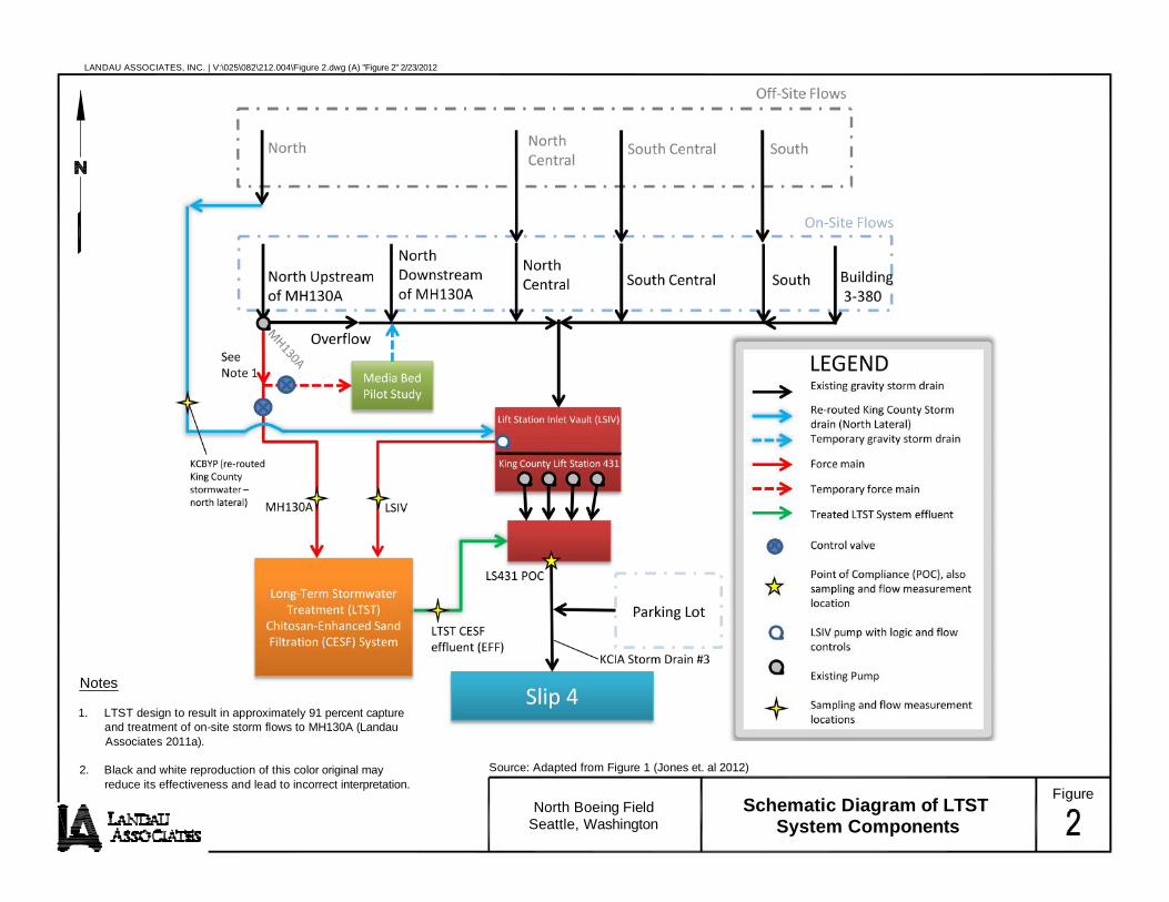
LANDAU ASSOCIATES, INC. | V:\025\082\212.004\Figure 2.dwg (A) "Figure 2" 2/23/2012
Notes
1. LTST design to result in approximately 91 percent capture and treatment of on-site storm flows to MH130A (Landau Associates 2011a).
2. Black and white reproduction of this color original may Source: Adapted from Figure 1 (Jones et. al 2012) reduce its effectiveness and lead to incorrect interpretation.
North Boeing Field Seattle, Washington
Schematic Diagram of LTST System Components
Figure

"S
"S
"S
!>
!>
!>
!>
!>
!>
!>
(To KCIA Storm Drain #3 EOF)
3-353
3-323
3-336
3-326 3-322
3-334
3-354
3-368
3-315
Georgetown Steam Plant
3-333
3-324
3-350
SL4-T5A(MH 178)
3-626
3-315
MH108
3-380 SL4-T5
Y:\Pr
ojects
\0250
82\21
2.004
\Figu
re 3.m
xd 2/
23/20
12 N
AD 19
83 St
atePla
ne W
ashin
gton N
orth F
IPS 46
01 Fe
et
Slip 4 LS431 SL4-T1 SL4-T4 3-313
SL4-T2 SL4-T3
3-369
3-390 SL4-T4A
Legend 0 160 320 Note1. Black and white reproduction of this color
! Sediment Trap NBF Storm Drain Structures North Lateral Drain Line South Lateral Drain Line > Scale in Feet original may reduce its effectiveness and Flow-weighted Water Short-Term Stormwater Treatment Facility North-Central Lateral Drain Line Drainage from Building 3-380 Area Storm Drain System Data Source: SAIC lead to incorrect interpretation. Sampling Location (using "S an ISCO autosampler) South-Central Lateral Drain Line Drainage from parking lot area FigureNorth Boeing Field STST Sampling Locations and
Seattle, Washington Pre-LTST Storm Drain Configuration 3

2/23/12 P:\025\082\LTST .311\FileRm\R\LTST Revised SAP\Figures\Base Files\LTST Revised SAP_Fig 4.doc Source: P\025\082\LTST .311\FileRm\R\100% Design Report\Apps\App C - SAP\SAP 062411\App C SAP_Tb 1.xlsx
Note: Data Presented is From Sampling Events Conducted From November 2010 to March 2011.
0
0.02
0.04
0.06
0.08
0.1
0.12
0.14
0.16
0.18
0.2
0 0.2 0.4 0.6 0.8 1 1.2 1.4 1.6 1.8 2
PCBs (µg/L)
Precipitation (in)
LS431
MH108
FigureNorth Boeing Field Whole Water PCB
Seattle, Washington Concentrations vs. Precipitation 4
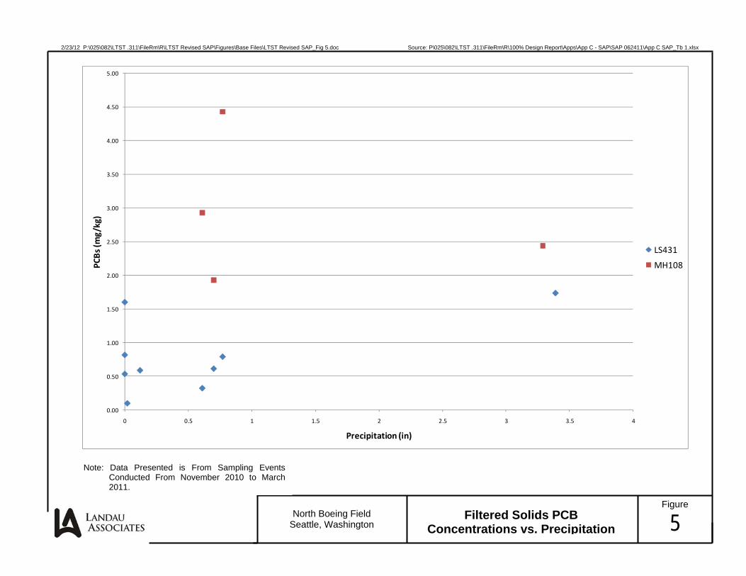
2/23/12 P:\025\082\LTST .311\FileRm\R\LTST Revised SAP\Figures\Base Files\LTST Revised SAP_Fig 5.doc Source: P\025\082\LTST .311\FileRm\R\100% Design Report\Apps\App C - SAP\SAP 062411\App C SAP_Tb 1.xlsx
Note: Data Presented is From Sampling Events Conducted From November 2010 to March 2011.
0.00
0.50
1.00
1.50
2.00
2.50
3.00
3.50
4.00
4.50
5.00
0 0.5 1 1.5 2 2.5 3 3.5 4
PCBs (m
g/kg)
Precipitation (in)
LS431
MH108
FigureNorth Boeing Field Filtered Solids PCB
Seattle, Washington Concentrations vs. Precipitation 5

"S
"S
"S
!>
!>
!>
!>
!>
!>
!>
!>!>
!
KCIA SD #3/PS44 EOF
3-353
3-323
3-336
3-326
3-322
3-334
3-354
3-368
Y:\Projects\025082\212.004\Figure 6.mxd 2/23/2012 NAD 1983 StatePlane Washington North FIPS 4601 Feet
Catch basin decommissioned This catch basin reconnected
to a point downstream of the reroute location SL4-T5A moved from this location (MH178)to the King County bypass line wet well and
Media Bed renamed SL4-T5A(2).Pilot Study Georgetown
Steam Plant 3-333
3-324
3-365 3-350 KCBYP
( t
King County Re-Route Begins
see no e 2) 3-626
3-315 SL4-T5A(2) MH130A
LS431 (see note 1)
3-380 SL4-T5
Slip 4 SL4-T1
CB433 LSIV SL4-T4
3-313
effluent sampling locations)
LTST CESF Facili(see Figure 7 - i l
MH130A and LTST nc
tyudes SL4-T2 3-369
SL4-T3 are covia the North Lateral
llected at the LTST (see F
Stormwater from MH130A is pumped and routed independently to the LTST Facility
Force Mai ln. Sampigure 7).
es
3-390 SL4-T4A
Legend ! Sediment Trap >
Flow-Weighted Water Sampling Location " (using an ISCO autosampler)S
NBF Storm Drain Structures
! Manhole 130A
North Lateral Drain Line
North-Central Lateral Drain Line
South-Central Lateral Drain Line
South Lateral Drain Line
Drainage from Building 3-380 Area
Drainage from Parking Lot Area
North Lateral Force Main (Direct to LTST Facility)
Re-Routed King County Storm Drain (North Lateral)
LTST Facility Location
LTST= Long-Term Stormwater Treatment CESF= Chitosan - Enhanced Sand Filtration LSIV= Lift Station Inlet Vault
Notes: 1. LS431 is the Point of Compliance (POC). 0 250 500
2. KCBYP is the sampling location for re routed King County stormwater - north Storm Drain System Data Source: SAIC Scale in Feet lateral.
FigureUpdated Storm Drain System 3. Black and white reproduction of this color North Boeing Field original may reduce its effectiveness and Seattle, Washington and LTST Sampling Locations lead to incorrect interpretation. 6
SL4-T3A
SL4-T2A
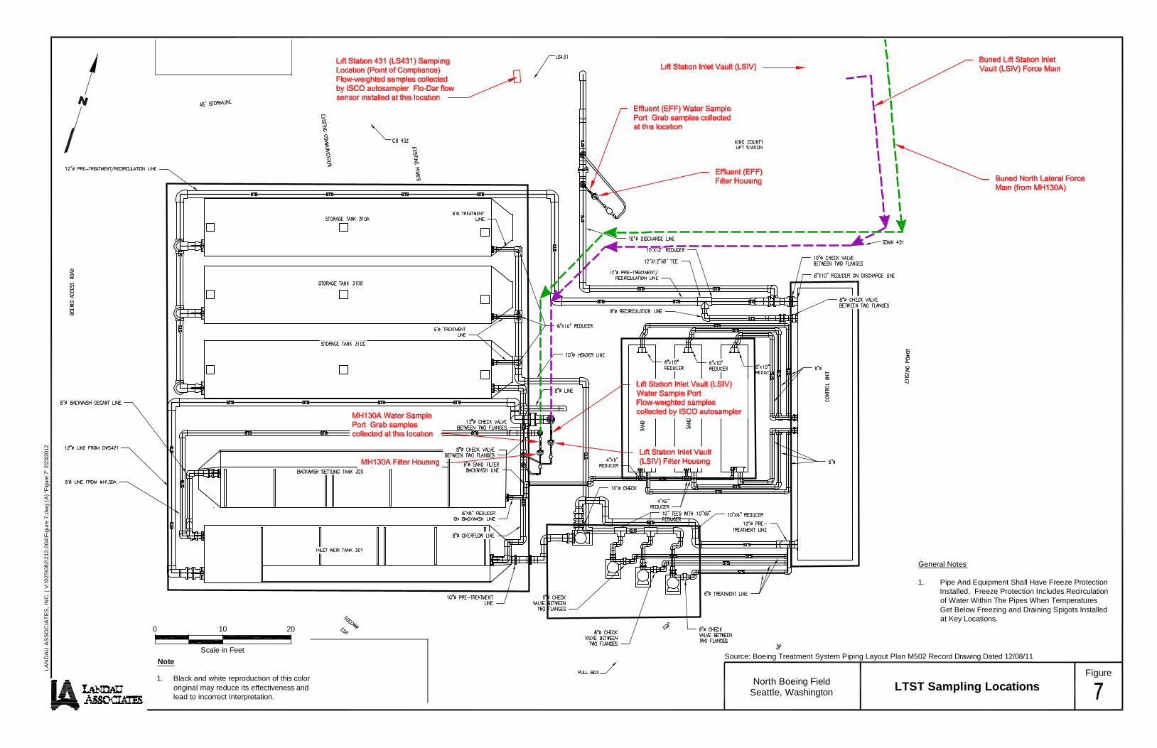
LAN
DA
U A
SS
OC
IATE
S, I
NC
. | V
:\025
\082
\212
.004
\Fig
ure
7.dw
g (A
) "Fi
gure
7" 2
/23/
2012
General Notes
1. Pipe And Equipment Shall Have Freeze Protection Installed. Freeze Protection Includes Recirculation of Water Within The Pipes When Temperatures Get Below Freezing and Draining Spigots Installed at Key Locations.
0 10 20
Scale in Feet Source: Boeing Treatment System Piping Layout Plan M502 Record Drawing Dated 12/08/11
Note Figure
1. Black and white reproduction of this color North Boeing Field original may reduce its effectiveness and LTST Sampling Locations Seattle, Washington lead to incorrect interpretation.

LANDAU ASSOCIATES, INC. | V:\025\082\212.004\Media Bed Pilot Study\Figure 8.dwg (A) "Figure 8" 2/23/2012
Source: Geosyntec Consultants
Figure North Boeing Field Schematic
Seattle, Washington Media Bed Pilot Study

TABLE 1 Page 1 of 1 LS431 AND MH108 STORMWATER ANALYTICAL RESULTS
NORTH BOEING FIELD - SEATTLE, WASHINGTON
Sample Location ID
Sample Collection Date
NBF-LS431-111710-W 11/17/10
NBF-LS431-113010-W
11/30/2010
NBF-LS431-121110-W
12/11/2010
NBF-LS431-012111-W
01/21/2011
NBF-LS431-012811-W
01/28/2011
NBF-LS431-030911-W
03/09/2011
NBF-LS431-032111-W
03/21/2011
NBF-MH108-111710-W 11/17/10
NBF-MH108-113010-W
11/30/2010
NBF-MH108-121210-W
12/12/2010
NBF-MH108-012111-W
01/21/2011
NBF-MH108-030911-W
03/09/2011
PCBs in Whole Water (a) Total PCBs (µg/L) 0.172 0.015 0.058 0.035 0.015 U
PRECIPITATION (b) Amount During Test (inches) 0.12 0.74 0.90 0.60 0
Sample Location ID
Sample Collection Date
NBF-LS431A-111710-S
11/17/10
NBF-LS431A-113010-S
11/30/10
NBF-LS431A-121210-S
12/12/10
NBF-LS431A-012111-S
01/21/2011
NBF-LS431A-012811-S
01/28/2011
PCBs in Filtered Solids Calculated Concentration of Total PCBs in Filtered Solids, Dry Weight (mg/kg) 0.58 0.79 1.7 0.32 0.81
PRECIPITATION (b) Amount During Test (inches) 0.12 0.77 3.39 0.61 0
NA = Not Analyzed. Bold = Detected compound.
U = Indicates the compound was undetected at the reported concentration.
(a) Total PCBs is the sum of detected aroclors or, if no aroclors are detected, is the largest reporting limit. (b) Precipitation data is from the NOAA Quality Controlled Local Climatological Data for Station 24234/BFI - SEATTLE: BOEING FIELD/KING COUNTY INTERNATIONAL AIRPORT.
0.045 0.013 0.050 0.013 0.017 0.053 0.101
0.53 0.02 0.12 0.74 1.86 0.61 0.70
NBF-LS431A- NBF-LS431A- NBF-MH108A- NBF-MH108A- NBF-MH108A- NBF-MH108A- NBF-MH108A-030911-S 032111-S 111710-S 113010-S 121210-S 012111-S 030911-S
03/09/2011 03/21/2011 11/17/10 11/30/10 12/12/10 01/21/2011 03/09/2011
0.61 0.09 NA 4.4 2.4 2.9 1.9
0.70 0.02 0.12 0.77 3.29 0.61 0.70
3/15/2012 P:\025\082\LTST 2012\FileRm\R\LTST SAP\Revised SAP 031612\Tables\LTST SAP_Tb 1.xlsx Table1 LANDAU ASSOCIATES

TABLE 2 Page 1 of 2 LONG-TERM REMOVAL ACTION SAMPLING AND ANALYSIS SUMMARY
NORTH BOEING FIELD - SEATTLE, WASHINGTON
Location Sample Type Sample Media Frequency (a) Parameters Analytical Methods
Lift Station (LS431) (Compliance Monitoring Point)
Whole Water (flow-weighted composite) Stormwater (b)
Monthly routine sampling (multiple day sampling period),
November 2011 - December 2012; Five additional 24-hour storm events of
≥0.5 inch precipitation,
November 1, 2011 - October 31, 2012
PCBs EPA Method 8082
TSS SM 2540D
Total & Dissolved Metals (k) EPA Methods 200.8, 7470 for Hg
SVOCs (k) EPA Method 8270D
PAHs (k) EPA SIM Method 8270D
PSD Ecology TAPE Method (m)
To be determined (c), starting January 2013
PCBs EPA Method 8082
TSS SM 2540D
Total & Dissolved Metals (k) EPA Methods 200.8, 7470 for Hg
SVOCs (k) EPA Method 8270D
PAHs (k) EPA SIM Method 8270D
PSD Ecology TAPE Method (m)
Long-Term Stormwater Treatment System
Whole Water Influent from MH130A (grab)
Stormwater (b)
Twice monthly in 2011, monthly in 2012 (d); To be determined (c) starting January 2013
PCBs EPA Method 8082
TSS SM 2540D
PSD Ecology TAPE Method (m)
Whole Water Influent from Lift Station Inlet Vault (composite)
Twice monthly in 2011, monthly in 2012 (d); To be determined (c) starting January 2013
PCBs EPA Method 8082
TSS SM 2540D
PSD Ecology TAPE Method (m)
Whole Water Effluent (grab) Twice monthly in 2011, monthly in 2012 (d); To be determined (c) starting January 2013
PCBs EPA Method 8082
TSS SM 2540D
PSD Ecology TAPE Method (m)
Whole Water Effluent (grab) (e) Twice monthly (f) Residual Chitosan Ecology approved procedure (g)
Filtered Solids Influent from MH130A
Stormwater Solids
Monthly through December 2012, including during the five 24-hr storm sampling events; To be determined (c) starting January 2013
PCBs EPA Method 8082
Monthly through December 2012; To be determined (c) starting January 2013
PSD PSEP-PS (j)
Metals (l) EPA Methods 6010/6020, 7471 for Hg
Filtered Solids Influent from Lift Station Inlet Vault
Monthly through December 2012, including during the five 24-hr storm sampling events; To be
determined (c) starting January 2013 PCBs EPA Method 8082
Monthly through December 2012; To be determined (c) starting January 2013
PSD PSEP-PS (j)
Metals (l) EPA Methods 6010/6020, 7471 for Hg
Filtered Solids Effluent (n) Monthly through December 2012, including during the five 24-hr storm sampling events; To be determined (c) starting January 2013
PCBs EPA Method 8082
Media Bed Pilot Study: Influent, Effluent from Cell A, and
Effluent from Cell B Whole Water (grab) Stormwater (b) Five storm events of >0.2 inch precipitation
and five dry weather events by July 1, 2012
PCBs EPA Method 8082 TSS SM 2540D PSD Ecology TAPE Method (m)
Total Organic Carbon SM 5310B or SM 5310C Dissolved Organic Carbon SM 5310B or SM 5310C
3/15/2012 P:\025\082\LTST 2012\FileRm\R\LTST SAP\Revised SAP 031612\Tables\LTST SAP_Tb 2.xlsx LANDAU ASSOCIATES

Lift Station (LS431)(Compliance Monitoring Point)
Whole Water(flow-weighted composite) Stormwater (b)
Monthly routine sampling(multiple day sampling period),
November 2011 - December 2012;Five additional 24-hour storm events of
≥0.5 inch precipitation,
November 1, 2011 - October 31, 2012
TABLE 2 Page 2 of 2 LONG-TERM REMOVAL ACTION SAMPLING AND ANALYSIS SUMMARY
NORTH BOEING FIELD - SEATTLE, WASHINGTON
Location Sample Type Sample Media Frequency (a) Parameters Analytical Methods
Sediment Traps [SL4-T1, SL4-T2, SL4-T3, SL4-T4, SL4-
T4A, SL4-T5, SL4-T5A(2) (q)] (SL4-T5A to be moved from MH178 to
King County bypass line wet well)
Annual Composite, Homogenized Stormwater Solids Annually (h)
PCBs PSDDA Method 8082
SVOCs PSDDA SVOCS SW8270D
Total Metals Method 6000-7000
NWTPH-Dx NWTPH-Dx (with acid silica gel cleanup)
Total Organic Carbon Plumb 1981
Percent Total Solids EPA 160.3 (modified for solids)
PSD PSEP-PS (j)
Weir and Storage Tanks, Sand Filter Media
Composite from 3 or More Grab Samples from Tank or Filter Vessel (grab locations
to result in both horizontal and vertical compositing)
Settled Solids As Needed (i)
PCBs EPA Method 8082
SVOCs EPA Method 8270D
Metals TCLP and/or Method 6000-7000
Petroleum Hydrocarbons NWTPH-Dx and NWTPH-Gx
Re-routed King County Stormwater -North Lateral (KCBYP)
(manhole west of 3-365 building)
Whole Water (flow-weighted composite) Stormwater (b)
Parallel w/ LS431 sampling: half of the routine monthly events,
November 1, 2011 - December 31, 2012, and two storm events,
November 1, 2011 - October 31, 2012
PCBs EPA Method 8082
TSS SM 2540D
Total & Dissolved Metals (k) EPA Methods 200.8, 7470 for Hg
PSD Ecology TAPE Method (m)
To be determined (c), starting January 2013
PCBs EPA Method 8082
TSS SM 2540D
Total & Dissolved Metals (k) EPA Methods 200.8, 7470 for Hg
PSD Ecology TAPE Method (m)
Contingency (o): Offsite Stormwater - Other Laterals (SL4-
T2A, SL4-T3A, SL4-T4A)
Whole Water (flow-weighted composite) Stormwater (b) Two events per location (p),
parallel w/ LS431 sampling
PCBs EPA Method 8082
TSS SM 2540D
Total & Dissolved Metals (k) EPA Methods 200.8, 7470 for Hg
PSD Ecology TAPE Method (m)
(a) Monitoring plan beginning November 2011. All sampling and analysis will be performed by Boeing/Landau Associates and Boeing's contract laboratory, unless otherwise noted. (b) Stormwater is defined as all liquids, including any particles dissolved therein, in the form of base flow, storm water runoff, snow melt runoff, and drainage, as well as all solids which enter the storm drain system. (c) For sampling in 2013, Boeing will propose to EPA a sampling frequency and sampling parameters based on the results from the November 2011 - October 2012 sampling events. (d) One LTST system influent/effluent sampling event per month will be performed during the monthly lift station (LS431) sampling event. (e) Whole water effluent grab samples for Residual Chitosan testing will be collected from the treatment facility effluent sample port by Clear Water Compliance Services. (f) Residual chitosan was never detected in weekly effluent samples from the STST facility, and there is extremely low probability of chitosan being able to pass through the sand filters. (g) Per CESF system O&M Manual, Ecology approves procedures for residual chitosan testing for each chitosan distributor. Testing will be conducted in accordance with distributor's approved procedures. (h) Depending on the quantity of solids collected in the sediment traps, the laboratory may not be able to analyze all parameters. Laboratory will weigh and report total mass of solids collected per sample location. Analysis of parameters will be prioritized in the order listed. Sediment trap sampling will continue indefinitely until such time that additional data collection is no longer needed to support source control efforts. (i) The thickness of accumulated solids (sludge) in the weir tank will be checked at least once per month to determine if solids should be removed. Prior to solids removal, a composite sample of the solids will be collected and analyzed for waste
characterization purposes. Composite sampling will also be done for used sand filter media prior to disposal. Subsequent waste characterization will not be necessary unless contaminant concentrations in the LTST influent change significantly. (j) Grain size fractionation/particle size distribution for solids samples will be conducted using Puget Sound Estuary Protocols (PSEP) method. When low volumes of sample are collected, grain size fractionation
will be accomplished using sedigraph for material less than 62.5 µm. (k) If sufficient volume is available, LS431 whole water samples will be analyzed for total and dissolved metals (arsenic, cadmium, chromium, copper, lead, mercury, nickel, and zinc), SVOCs, and PAHs to support
Ecology's NBF-GTSP remedial investigation activities. (l) When sufficient volume is available, LTST filtered solids samples will be analyzed for metals (arsenic, cadmium, chromium, copper, lead, mercury, nickel, and zinc) to support Ecology's NBF-GTSP remedial investigation activities. (m) The preferred method for particle size distribution (PSD) will continue to be evaluated as the results are received. (n) From experience with STST filtered solids collection, there will not be enough solids collected in the LTST effluent filter for metals or PSD analysis. Therefore, we do not propose to filter for metals or PSD analysis at the LTST effluent. (o) Sampling of stormwater from offsite KCIA sources may be performed to assess KCIA stormwater impact on compliance with EPA Interim Goals. (p) Sampling of some or all events at these locations may not be feasible, as the locations are on the flightline and safety concerns and regulations may interfere with sampling activities. (q) Location SL4-T5A(2) does not have a bracket and Teflon container like the other sediment trap locations; SL4-T5A(2) shall be sampled by collecting solids from the bottom of the wet well, which collects solids behind a permanent weir.
3/15/2012 P:\025\082\LTST 2012\FileRm\R\LTST SAP\Revised SAP 031612\Tables\LTST SAP_Tb 2.xlsx LANDAU ASSOCIATES

Page 1 of 2 TABLE 3
ANALYTICAL METHODS AND TARGET REPORTING LIMITS LONG-TERM STORMWATER TREATMENT SAMPLING
NORTH BOEING FIELD - SEATTLE, WASHINGTON
Analyte
Analytical
Method (a)
Target Reporting Limits (b)
Water Filtered Solids Unfiltered Solids
ARI
RL (c)
Lancaster
LOQ (d)
ARI
RL (c)
Lancaster
LOQ (d)
Sediment Traps Residual Solids
ARI RL (c) Lancaster LOQ (d) ARI RL (c) Lancaster LOQ (d)
PCBs Aroclor 1016 Aroclor 1221 Aroclor 1232 Aroclor 1242 Aroclor 1248 Aroclor 1254 Aroclor 1260 Aroclor 1262
CONVENTIONALS
Total Suspended Solids Total Organic Carbon Dissolved Organic Carbon
PARTICLE SIZE DISTRIBUTION
Particle Size Distribution
Total Petroleum Hydrocarbons
Diesel-Range Motor Oil-Range Gasoline-Range
EPA Method 8082 (e) EPA Method 8082 (e) EPA Method 8082 (e) EPA Method 8082 (e) EPA Method 8082 (e) EPA Method 8082 (e) EPA Method 8082 (e) EPA Method 8082 (e)
SM 2540 SM 5310B / SM 5310C / Plumb 1981
SM 5310B / SM 5310C
PSEP-PS/Ecology TAPE Method
NWTPH-Dx (f,g) NWTPH-Dx (f,g) NWTPH-Gx (f)
0.01 µg/L 0.01 µg/L 0.01 µg/L 0.01 µg/L 0.01 µg/L 0.01 µg/L 0.01 µg/L 0.01 µg/L
1 mg/L 0.6 mg/L 0.6 mg/L
---
-
0.01 µg/L 0.01 µg/L 0.01 µg/L 0.01 µg/L 0.01 µg/L 0.01 µg/L 0.01 µg/L 0.01 µg/L
3 mg/L 1 mg/L 1 mg/L
-
---
0.5 µg 0.5 µg 0.5 µg 0.5 µg 0.5 µg 0.5 µg 0.5 µg 0.5 µg
-
--
-
-
--
0.5 µg 0.5 µg 0.5 µg 0.5 µg 0.5 µg 0.5 µg 0.5 µg 0.5 µg
-
--
-
---
10 µg/kg 10 µg/kg 10 µg/kg 10 µg/kg 10 µg/kg 10 µg/kg 10 µg/kg
0.02 percent
5.0 mg/kg 10.0 mg/kg
-
-
-
-
-
10 µg/kg 10 µg/kg 10 µg/kg 10 µg/kg 10 µg/kg 10 µg/kg 10 µg/kg
0.03 percent
7.0 mg/kg 30 mg/kg
-
-
-
-
-
33 µg/kg 33 µg/kg 33 µg/kg 33 µg/kg 33 µg/kg 33 µg/kg 33 µg/kg
5.0 mg/kg 10.0 mg/kg
5.0 mg/kg
-
-
-
-
-
17 µg/kg 17 µg/kg 17 µg/kg 17 µg/kg 17 µg/kg 17 µg/kg 17 µg/kg
7.0 mg/kg 30.0 mg/kg
5.0 mg/kg
-
-
--
--
METALS Arsenic Barium Cadmium Chromium Copper Lead Mercury (total) Mercury (dissovled) Nickel Selenium Silver Zinc
EPA Method 200.8/6010 or 6020 EPA Method 200.8/6010 or 6020 EPA Method 200.8/6010 or 6020 EPA Method 200.8/6010 or 6020 EPA Method 200.8/6010 or 6020 EPA Method 200.8/6010 or 6020
EPA Method 7470/7471 EPA Method 7470/7471
EPA Method 200.8/6010 or 6020 EPA Method 200.8/6010 or 6020 EPA Method 200.8/6010 or 6020 EPA Method 200.8/6010 or 6020
0.5 µg/L
0.1 µg/L 0.5 µg/L 0.5 µg/L 0.1 µg/L 0.1 µg/L
0.02 µg/L 0.5 µg/L
4.0 µg/L
-
--
2 µg/L
0.5 µg/L 2 µg/L 2 µg/L 1 µg/L
0.2 µg/L 0.2 µg/L
2 µg/L
15 µg/L --
-5.0 mg/kg
0.2 mg/kg 0.5 mg/kg 0.2 mg/kg 2.0 mg/kg
0.025 mg/kg
1.0 mg/kg
1.0 mg/kg
-
-
-
-
2.0 mg/kg
0.1 mg/kg 0.4 mg/kg 0.4 mg/kg 0.2 mg/kg 0.1 mg/kg
0.4 mg/kg
2.0 mg/kg
-
-
--
5.0 mg/kg
0.2 mg/kg 2.0 mg/kg
0.025 mg/kg
1.0 mg/kg
-
--
-
-
--
2.0 mg/kg
0.4 mg/kg 0.2 mg/kg 0.1 mg/kg
2.0 mg/kg
---
---
-
5.0 mg/kg 0.3 mg/kg 0.2 mg/kg 0.5 mg/kg
2.0 mg/kg 0.025 mg/kg
5.0 mg/kg 0.3 mg/kg
-
-
-
-
2.0 mg/kg 0.5 mg/kg 0.1 mg/kg 0.4 mg/kg
0.2 mg/kg 0.1 mg/kg
2.0 mg/kg 0.5 mg/kg
-
--
--
TCLP METALS Arsenic Barium Cadmium Chromium Lead Mercury Selenium Silver
EPA Method 1311/6010 EPA Method 1311/6010 EPA Method 1311/6010 EPA Method 1311/6010 EPA Method 1311/6010 EPA Method 1311/7471 EPA Method 1311/6010 EPA Method 1311/6010
---
-----
---
-----
------
--
-
--
-----
--
--
-
--
-
--
---
-
--
0.2 mg/L 0.2 mg/L
0.01 mg/L 0.02 mg/L
0.1 mg/L 0.0002 mg/L
0.2 mg/L 0.02 mg/L
0.02 mg/L 0.005 mg/L 0.005 mg/L 0.015 mg/L 0.015 mg/L
0.0002 mg/L 0.02 mg/L
0.005 mg/L
SEMIVOLATILES Phenol Bis-(2-Chloroethyl) Ether 2-Chlorophenol 1,3-Dichlorobenzene 1,4-Dichlorobenzene Benzyl Alcohol 1,2-Dichlorobenzene 2-Methylphenol 2,2'-Oxybis(1-Chloropropane) 4-Methylphenol N-Nitroso-Di-N-Propylamine Hexachloroethane Nitrobenzene Isophorone 2-Nitrophenol 2,4-Dimethylphenol Benzoic Acid bis(2-Chloroethoxy) Methane 2,4-Dichlorophenol 1,2,4-Trichlorobenzene Naphthalene 4-Chloroaniline Hexachlorobutadiene 4-Chloro-3-methylphenol 1-Methylnaphthalene 2-Methylnaphthalene Hexachlorocyclopentadiene 2,4,6-Trichlorophenol 2,4,5-Trichlorophenol 2-Chloronaphthalene 2-Nitroaniline Dimethylphthalate Acenaphthylene
SW 8270D (h) SW 8270D SW 8270D
SW 8270D (h) SW 8270D (h) SW 8270D (h) SW 8270D (h) SW 8270D (h)
SW 8270D SW 8270D (h)
SW 8270D SW 8270D (h)
SW 8270D SW 8270D SW 8270D
SW 8270D (h) SW 8270D (h)
SW 8270D SW 8270D
SW 8270D (h) SW 8270D (h,i)
SW 8270D SW 8270D (h)
SW 8270D SW 8270D (h) SW 8270D (h,i)
SW 8270D SW 8270D SW 8270D SW 8270D SW 8270D
SW 8270D (h) SW 8270D (h,i)
1.0 µg/L
1.0 µg/L 5.0 µg/L 1.0 µg/L 1.0 µg/L
1.0 µg/L
1.0 µg/L 10.0 µg/L
1.0 µg/L 0.01 µg/L
1.0 µg/L
0.01 µg/L
1.0 µg/L 0.01 µg/L
--
-
-
-
-
--
--
--
--
---
--
1 µg/L
1 µg/L 15 µg/L
1 µg/L 1 µg/L
1 µg/L
1 µg/L 15 µg/L
1 µg/L 0.05 µg/L
1 µg/L
0.05 µg/L
5 µg/L 0.05 µg/L
--
-
-
-
--
--
--
-
-----
-
-
--
----
-----
----
--
-
--
-------
-
-
-
--
-
-----
-
-------------
---
-----
------
20 µg/kg
20 µg/kg 20 µg/kg 20 µg/kg 20 µg/kg 20 µg/kg
20 µg/kg
20 µg/kg
20 µg/kg 100 µg/kg
100 µg/kg 20 µg/kg
20 µg/kg
20 µg/kg 100 µg/kg
100 µg/kg 20 µg/kg
-
-----
---
-
-
-
-
--
-
33 µg/kg
33 µg/kg 33 µg/kg
500 µg/kg 33 µg/kg 33 µg/kg
33 µg/kg
167 µg/kg
33 µg/kg 500 µg/kg
33 µg/kg 17 µg/kg
33 µg/kg
17 µg/kg 17 µg/kg
167 µg/kg 17 µg/kg
---
--
-
-
---
--
--
-
-
67 µg/kg 67 µg/kg 67 µg/kg 67 µg/kg 67 µg/kg
330 µg/kg 67 µg/kg 67 µg/kg 67 µg/kg 67 µg/kg 67 µg/kg 67 µg/kg 67 µg/kg 67 µg/kg 67 µg/kg 67 µg/kg
670 µg/kg 67 µg/kg
330 µg/kg 67 µg/kg 67 µg/kg
330 µg/kg 67 µg/kg
330 µg/kg 67 µg/kg 67 µg/kg
330 µg/kg 330 µg/kg 330 µg/kg
67 µg/kg 330 µg/kg
67 µg/kg 67 µg/kg
33 µg/kg 33 µg/kg 33 µg/kg 33 µg/kg 33 µg/kg
500 µg/kg 33 µg/kg 33 µg/kg 33 µg/kg 33 µg/kg 33 µg/kg
167 µg/kg 33 µg/kg 33 µg/kg 33 µg/kg 33 µg/kg
500 µg/kg 33 µg/kg 33 µg/kg 33 µg/kg 17 µg/kg 33 µg/kg 33 µg/kg 33 µg/kg 17 µg/kg 17 µg/kg
500 µg/kg 33 µg/kg 33 µg/kg 33 µg/kg 33 µg/kg
167 µg/kg 17 µg/kg
3/15/2012 P:\025\082\LTST 2012\FileRm\R\LTST SAP\Revised SAP 031612\Tables\LTST SAP_Tb 3.xlsx Table 3 LANDAU ASSOCIATES

Page 2 of 2 TABLE 3
ANALYTICAL METHODS AND TARGET REPORTING LIMITS LONG-TERM STORMWATER TREATMENT SAMPLING
NORTH BOEING FIELD - SEATTLE, WASHINGTON
Analyte
Analytical
Method (a)
Target Reporting Limits (b)
Water Filtered Solids Unfiltered Solids
ARI
RL (c)
Lancaster
LOQ (d)
ARI
RL (c)
Lancaster
LOQ (d)
Sediment Traps Residual Solids
ARI RL (c) Lancaster LOQ (d) ARI RL (c) Lancaster LOQ (d)
SEMIVOLATILES (continued) 3-Nitroaniline SW 8270D - - - - - - 330 µg/kg 167 µg/kg Acenaphthene SW 8270D (h,i) 0.01 µg/L 0.05 µg/L - - 100 µg/kg 17 µg/kg 67 µg/kg 17 µg/kg 2,4-Dinitrophenol SW 8270D - - - - - - 670 µg/kg 1000 µg/kg 4-Nitrophenol SW 8270D - - - - - - 330 µg/kg 500 µg/kg Dibenzofuran SW 8270D (h,i) 0.01 µg/L 0.05 µg/L - - 100 µg/kg 33 µg/kg 67 µg/kg 33 µg/kg 2,6-Dinitrotoluene SW 8270D - - - - - - 330 µg/kg 33 µg/kg 2,4-Dinitrotoluene SW 8270D - - - - - - 330 µg/kg 167 µg/kg Diethylphthalate SW 8270D (h) 1.0 µg/L 5 µg/L - - 100 µg/kg 167 µg/kg 67 µg/kg 167 µg/kg 4-Chlorophenyl-phenylether SW 8270D - - - - - - 67 µg/kg 33 µg/kg Fluorene SW 8270D (h,i) 0.01 µg/L 0.05 µg/L - - 20 µg/kg 17 µg/kg 67 µg/kg 17 µg/kg 4-Nitroaniline SW 8270D - - - - - - 330 µg/kg 167 µg/kg 4,6-Dinitro-2-Methylphenol SW 8270D - - - - - - 670 µg/kg 500 µg/kg N-Nitrosodiphenylamine SW 8270D (h) 1.0 µg/L 1 µg/L - - 20 µg/kg 33 µg/kg 67 µg/kg 33 µg/kg 4-Bromophenyl-phenylether SW 8270D - - - - - - 67 µg/kg 33 µg/kg Hexachlorobenzene SW 8270D (h) 1.0 µg/L 0.5 µg/L - - 20 µg/kg 17 µg/kg 67 µg/kg 17 µg/kg Pentachlorophenol SW 8270D (h) 5.0 µg/L 5 µg/L - - 20 µg/kg 170 µg/kg 330 µg/kg 170 µg/kg Phenanthrene SW 8270D (h,i) 0.01 µg/L 0.05 µg/L - - 20 µg/kg 17 µg/kg 67 µg/kg 17 µg/kg Carbazole SW 8270D - - - - - - 67 µg/kg 33 µg/kg Anthracene SW 8270D (h,i) 0.01 µg/L 0.05 µg/L - - 20 µg/kg 17 µg/kg 67 µg/kg 17 µg/kg Di-n-Butylphthalate SW 8270D (h) 1.0 µg/L 5 µg/L - - 20 µg/kg 167 µg/kg 67 µg/kg 167 µg/kg Fluoranthene SW 8270D (h,i) 0.01 µg/L 0.05 µg/L - - 20 µg/kg 17 µg/kg 67 µg/kg 17 µg/kg Pyrene SW 8270D (h,i) 0.01 µg/L 0.05 µg/L - - 100 µg/kg 17 µg/kg 67 µg/kg 17 µg/kg Butylbenzylphthalate SW 8270D (h) 1.0 µg/L 5 µg/L - - 20 µg/kg 167 µg/kg 67 µg/kg 167 µg/kg 3,3'-Dichlorobenzidine SW 8270D - - - - - - 330 µg/kg 333 µg/kg Benzo(a)anthracene SW 8270D (h,i) 0.01 µg/L 0.01 µg/L - - 20 µg/kg 17 µg/kg 67 µg/kg 17 µg/kg bis(2-Ethylhexyl)phthalate SW 8270D (h) 1.0 µg/L 5 µg/L - - 20 µg/kg 170 µg/kg 67 µg/kg 170 µg/kg Chrysene SW 8270D (h,i) 0.01 µg/L 0.01 µg/L - - 20 µg/kg 17 µg/kg 67 µg/kg 17 µg/kg Total benzofluoranthenes SW 8270D (h,i) 0.02 µg/L - - - 20 µg/kg - 67 µg/kg -Benzo(b)fluoranthene SW 8270D (h,i) - 0.01 µg/L - - - 17 µg/kg - 17 µg/kg Benzo(k)fluoranthene SW 8270D (h,i) - 0.01 µg/L - - - 17 µg/kg - 17 µg/kg Di-n-Octyl phthalate SW 8270D (h) 1.0 µg/L 5 µg/L - - 20 µg/kg 167 µg/kg 67 µg/kg 167 µg/kg Benzo(a)pyrene SW 8270D (h,i) 0.01 µg/L 0.01 µg/L - - 20 µg/kg 17 µg/kg 67 µg/kg 17 µg/kg Indeno(1,2,3-cd)pyrene SW 8270D (h,i) 0.01 µg/L 0.01 µg/L - - 20 µg/kg 17 µg/kg 67 µg/kg 17 µg/kg Dibenz(a,h)anthracene SW 8270D (h,i) 0.01 µg/L 0.01 µg/L - - 20 µg/kg 17 µg/kg 67 µg/kg 17 µg/kg Benzo(g,h,i)perylene SW 8270D (h,i) 0.01 µg/L 0.05 µg/L - - 20 µg/kg 17 µg/kg 67 µg/kg 17 µg/kg
ARI = Analytical Resources, Inc. Lancaster = Lancaster Laboratories, Inc. RL = Reporting Limit LOQ = Limit of Quantification SM = Standard Method
(a) Analytical methods are from SW-846 (EPA 1986) and updates unless otherwise noted. (b) Reporting limits goals are based on current laboratory data and may be modified during the transition to the new laboratory, Lancaster Laboratories. Instances may arise where high sample concentrations, nonhomogeneity of samples, total solids (percent of sample that is solids), or matrix interferences, preclude achieving the desired reporting limits. (c) ARI reporting will be based on the lowest standard on the calibration curve. (d) The lowest standard on Lancaster's calibration curve will be at or below the LOQ. (e) Sediment trap solids will be analyzed by PSDDA Method 8082. (f) Methods NWTPH-Dx and NWTPH-Gx as described in Analytical Methods for Petroleum Hydrocarbons, Washington State Department of Ecology, Publication ECY97-602, June 1997 (Ecology 1997) (g) For NWTPH-Dx analyses, an acid silica gel cleanup will be performed for sediment trap solids, but not for residual solids. (h) Sediment trap samples will be analyzed by PSDDA Method 8270D. (i) Water samples will be analyzed by SW 8270D Selective Ion Monitoring (SIM).
3/15/2012 P:\025\082\LTST 2012\FileRm\R\LTST SAP\Revised SAP 031612\Tables\LTST SAP_Tb 3.xlsx Table 3 LANDAU ASSOCIATES
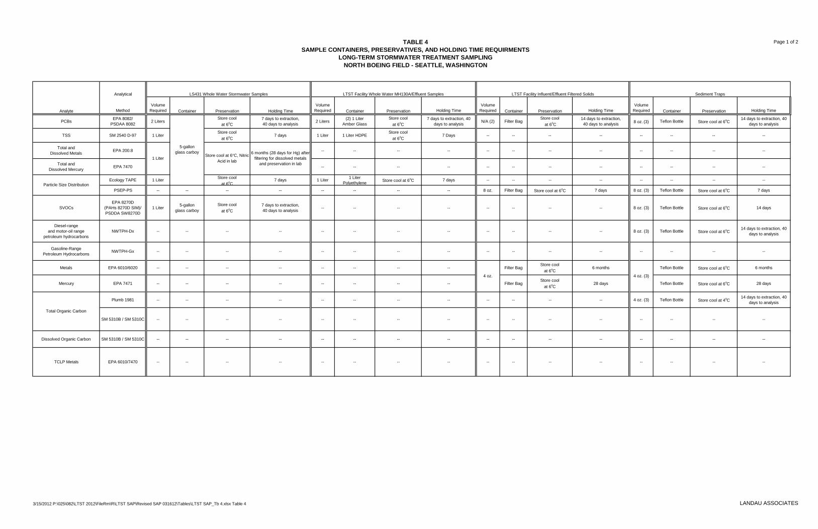
TABLE 4 Page 1 of 2
SAMPLE CONTAINERS, PRESERVATIVES, AND HOLDING TIME REQUIRMENTS LONG-TERM STORMWATER TREATMENT SAMPLING
NORTH BOEING FIELD - SEATTLE, WASHINGTON
Analyte
Analytical
Method
LS431 Whole Water Stormwater Samples LTST Facility Whole Water MH130A/Effluent Samples LTST Facility Influent/Effluent Filtered Solids Sediment Traps
Volume Required Container Preservation Holding Time
Volume Required Container Preservation Holding Time
Volume Required Container Preservation Holding Time
Volume Required Container Preservation Holding Time
PCBs EPA 8082/ PSDAA 8082 2 Liters
5-gallon glass carboy
Store cool at 6oC
7 days to extraction, 40 days to analysis 2 Liters (2) 1 Liter
Amber Glass Store cool
at 6oC 7 days to extraction, 40
days to analysis N/A (2) Filter Bag Store cool
at 6oC 14 days to extraction, 40 days to analysis 8 oz. (3) Teflon Bottle Store cool at 6oC
14 days to extraction, 40 days to analysis
TSS SM 2540 D-97 1 Liter Store cool
at 6oC 7 days 1 Liter 1 Liter HDPE
Store cool at 6oC
7 Days -- -- -- -- -- -- -- --
Total and Dissolved Metals EPA 200.8
1 Liter Store cool at 6°C, Nitric
Acid in lab
6 months (28 days for Hg) after filtering for dissolved metals
and preservation in lab
-- -- -- -- -- -- -- -- -- -- -- --
Total and Dissolved Mercury EPA 7470 -- -- -- -- -- -- -- -- -- -- -- --
Particle Size Distribution Ecology TAPE 1 Liter Store cool
at 6oC 7 days 1 Liter 1 Liter
Polyethylene Store cool at 6oC 7 days -- -- -- -- -- -- -- --
PSEP-PS -- -- -- -- -- -- -- -- 8 oz. Filter Bag Store cool at 6oC 7 days 8 oz. (3) Teflon Bottle Store cool at 6oC 7 days
SVOCs EPA 8270D
(PAHs 8270D SIM)/ PSDDA SW8270D
1 Liter 5-gallon glass carboy
Store cool at 6oC
7 days to extraction, 40 days to analysis -- -- -- -- -- -- -- -- 8 oz. (3) Teflon Bottle Store cool at 6oC 14 days
Diesel-range and motor-oil range
petroleum hydrocarbons NWTPH-Dx -- -- -- -- -- -- -- -- -- -- -- -- 8 oz. (3) Teflon Bottle Store cool at 6oC
14 days to extraction, 40 days to analysis
Gasoline-Range Petroleum Hydrocarbons NWTPH-Gx -- -- -- -- -- -- -- -- -- -- -- -- -- -- -- --
Metals EPA 6010/6020 -- -- -- -- -- -- -- --
4 oz.
Filter Bag Store cool
at 6oC 6 months
4 oz. (3)
Teflon Bottle Store cool at 6oC 6 months
Mercury EPA 7471 -- -- -- -- -- -- -- -- Filter Bag Store cool
at 6oC 28 days Teflon Bottle Store cool at 6oC 28 days
Total Organic Carbon
Plumb 1981 -- -- -- -- -- -- -- -- -- -- -- -- 4 oz. (3) Teflon Bottle Store cool at 4oC 14 days to extraction, 40
days to analysis
SM 5310B / SM 5310C -- -- -- -- -- -- -- -- -- -- -- -- -- -- -- --
Dissolved Organic Carbon SM 5310B / SM 5310C -- -- -- -- -- -- -- -- -- -- -- -- -- -- -- --
TCLP Metals EPA 6010/7470 -- -- -- -- -- -- -- -- -- -- -- -- -- -- -- --
3/15/2012 P:\025\082\LTST 2012\FileRm\R\LTST SAP\Revised SAP 031612\Tables\LTST SAP_Tb 4.xlsx Table 4 LANDAU ASSOCIATES
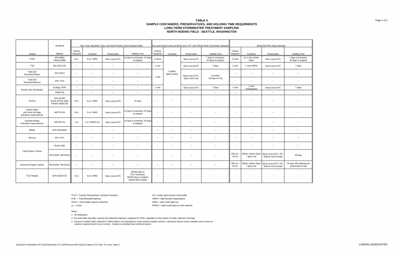
TABLE 4 Page 2 of 2
SAMPLE CONTAINERS, PRESERVATIVES, AND HOLDING TIME REQUIRMENTS LONG-TERM STORMWATER TREATMENT SAMPLING
NORTH BOEING FIELD - SEATTLE, WASHINGTON
Analyte
Analytical
Method
Weir Tank, Backflush Tank, and Sand Filtration Units Residual Solids Re-routed King County (KCBYP) and LTST LSIV Whole Water Stormwater Samples Media Bed Pilot Study Samples
Volume Required Container Preservation Holding Time
Volume Required Container Preservation Holding Time
Volume Required Container Preservation Holding Time
PCBs EPA 8082/ PSDAA 8082 8 oz. 8 oz. WMG Store cool at 6oC
14 days to extraction, 40 days to analysis 2 Liters
5-gallon glass carboy
Store cool at 6oC 7 days to extraction, 40 days to analysis 2 Liters (2) 1 Liter Amber
Glass Store cool at 6oC 7 days to extraction, 40 days to analysis
TSS SM 2540 D-97 -- -- -- -- 1 Liter Store cool at 6oC 7 days 1 Liter 1 Liter HDPE Store cool at 6oC 7 days
Total and Dissolved Metals EPA 200.8 -- -- -- --
1 Liter Store cool at 6oC, Nitric Acid in lab
6 months 28 days for Hg
-- -- -- --
Total and Dissolved Mercury EPA 7470 -- -- -- -- -- -- -- --
Particle Size Distribution Ecology TAPE -- -- -- -- 1 Liter Store cool at 6oC 7 days 1 Liter 1 Liter
Polyethylene Store cool at 6oC 7 days
PSEP-PS -- -- -- -- -- -- -- -- -- -- -- --
SVOCs EPA 8270D
(PAHs 8270D SIM)/ PSDDA SW8270D
8 oz. 8 oz. WMG Store cool at 6oC 14 days -- -- -- -- -- -- -- --
Diesel-range and motor-oil range
petroleum hydrocarbons NWTPH-Dx 8 oz. 8 oz. WMG Store cool at 6oC
14 days to extraction, 40 days to analysis -- -- -- -- -- -- -- --
Gasoline-Range Petroleum Hydrocarbons NWTPH-Gx 2 oz. 2 oz. WMGS (1) Store cool at 6oC
14 days to extraction, 40 days to analysis -- -- -- -- -- -- -- --
Metals EPA 6010/6020 -- -- -- -- -- -- -- -- -- -- -- --
Mercury EPA 7471 -- -- -- -- -- -- -- -- -- -- -- --
Total Organic Carbon
Plumb 1981 -- -- -- -- -- -- -- -- -- -- -- --
SM 5310B / SM 5310C -- -- -- -- -- -- -- -- 250 mL / 40 mL
250mL Amber Glass / glass vial
Store cool at 6oC / 4oC, Sulfuric Acid in bottle
28 days
Dissolved Organic Carbon SM 5310B / SM 5310C -- -- -- -- -- -- -- -- 250 mL / 40 mL
250mL Amber Glass / glass vial
Store cool at 6oC / 4oC, Sulfuric Acid in bottle
28 days after filtering and preservation in lab
TCLP Metals EPA 6010/7470 8 oz 8 oz. WMG Store cool at 6oC
28/180 days to TCLP extraction,
28/180 days to analysis (Hg/all other metals)
-- -- -- -- -- -- -- --
TCLP = Toxicity Characteristic Leachate Procedure AG = amber glass boston round bottle PCB = Polychlorinated biphenyl HDPE = High Density Polypropylene SVOC = Semivolatile organic compound WMG = wide mouth glass jar oz. = ounce WMGS = wide mouth glass jar with septa lid
Notes: 1. No headspace. 2. The entire filter bag (filter material and collected material) is analyzed for PCBs, regardless of the volume of solids collected in the bag. 3. Amount of settled solids collected in Teflon bottle is not anticipated to meet required sample volumes. Laboratory will pre-screen samples and cut back on
volumes required based on pre-screens. Analysis is prioritized due to limited volume.
3/15/2012 P:\025\082\LTST 2012\FileRm\R\LTST SAP\Revised SAP 031612\Tables\LTST SAP_Tb 4.xlsx Table 4 LANDAU ASSOCIATES

TABLE 5 Page 1 of 1
PROJECT SCHEDULE 2011-2012 LONG-TERM STORMWATER TREATMENT
NORTH BOEING FIELD, SEATTLE, WASHINGTON
Event/Document Date / Due Date (submittal to EPA)
Operation of LTST CESF System Begins October 28, 2011
Monthly Progress Reports 5th day of the following month, or first business day after
Media Bed Pilot Study Sampling Program Completed July 1, 2012
Media Bed Pilot Study Summary Report (final) August 17, 2012
Year 1 of LTST Monitoring Completed October 31, 2012
Annual LTST Performance Evaluation Report (draft) December 3, 2012
Meeting to discuss results of Annual Report and recommendations for future monitoring December 10, 2012
Annual LTST Performance Evaluation Report (final) December 17, 2012 (or 14 days following written EPA comments)
3/15/2012 P:\025\082\LTST 2012\FileRm\R\LTST SAP\Revised SAP 031612\Tables\LTST SAP_Tb 5.xlsx Table 5 LANDAU ASSOCIATES

TABLE 6 Page 1 of 2 EXAMPLE SAMPLING PROGRAM SUMMARY
LONG-TERM STORMWATER TREATMENT NORTH BOEING FIELD - SEATTLE, WASHINGTON
Location Sample Type Sample Media Frequency (a) Parameters Dates Sampled
Lift Station (LS431) (Compliance Monitoring Point)
Whole Water (flow-weighted composite) Stormwater (b)
Monthly routine sampling (multiple day sampling period),
November 2011 - December 2012; Five additional 24-hour storm events of
≥0.5 inch precipitation,
November 1, 2011 - October 31, 2012
PCBs
Monthly Events: 11/11/11, 12/8/11 Storm Events: 11/17/11, 11/23/11, 12/28/11
TSS
Total & Dissolved Metals (c)
SVOCs (c)
PAHs (c)
PSD
To be determined (d), starting January 2013
PCBs
TSS
Total & Dissolved Metals (c)
SVOCs (c)
PAHs (c)
PSD
Long-Term Stormwater Treatment System
Whole Water Influent from MH130A (grab)
Stormwater (b)
Twice monthly in 2011, monthly in 2012 (e); To be determined (d) starting January 2013
PCBs Monthly Events: 11/08/11, 12/05/11, 12/21/11 Storm Events: 11/16/11, 11/22/11, 12/27/11
TSS
PSD
Whole Water Influent from Lift Station Inlet Vault (composite)
Twice monthly in 2011, monthly in 2012 (e); To be determined (d) starting January 2013
PCBs Monthly Events: 11/11/11, 12/8/11, 12/21/11 Storm Events: 11/17/11, 11/23/11, 12/28/11
TSS
PSD
Whole Water Effluent (grab) Twice monthly in 2011, monthly in 2012 (e); To be determined (d) starting January 2013
PCBs Monthly Events: 11/08/11, 12/05/11, 12/20/11 Storm Events: 11/16/11, 11/22/11, 12/27/11
TSS
PSD
Whole Water Effluent (grab) (f) Twice monthly (g) Residual Chitosan
Filtered Solids Influent from MH130A
Stormwater Solids
Monthly through December 2012, including during the five 24-hr storm sampling events; To be
determined (d) starting January 2013 PCBs
Monthly Events: 11/11/11, 12/8/11 Storm Events: 11/17/11, 11/23/11, 12/28/11
Monthly through December 2012; To be determined (d) starting January 2013
PSD Interim Events: 11/16/11, 12/15/11
Metals (h,i)
Filtered Solids Influent from Lift Station Inlet Vault
Monthly through December 2012, including during the five 24-hr storm sampling events; To be
determined (d) starting January 2013 PCBs
Monthly Events: 11/11/11, 12/8/11, 12/21/11 Storm Events: 11/17/11, 11/23/11, 12/28/11
Monthly through December 2012; To be determined (d) starting January 2013
PSD Interim Events: 11/16/11, 12/15/11
Metals (h,i)
Filtered Solids Effluent (j) Monthly through December 2012, including during
the five 24-hr storm sampling events; To be determined (d) starting January 2013
PCBs
Monthly Events: 11/11/11, 12/8/11 Storm Events: 11/17/11, 11/23/11, 12/28/11
Media Bed Pilot Study: Influent, Effluent from Cell A, and
Effluent from Cell B Whole Water (grab) Stormwater (b) Five storm events of >0.2 inch precipitation and
five dry weather events by July 1, 2012
PCBs TSS PSD
Total Organic Carbon Dissolved Organic Carbon
3/15/2012 P:\025\082\LTST 2012\FileRm\R\LTST SAP\Revised SAP 031612\Tables\LTST SAP_Tb 6.xlsx Sampling Program LANDAU ASSOCIATES
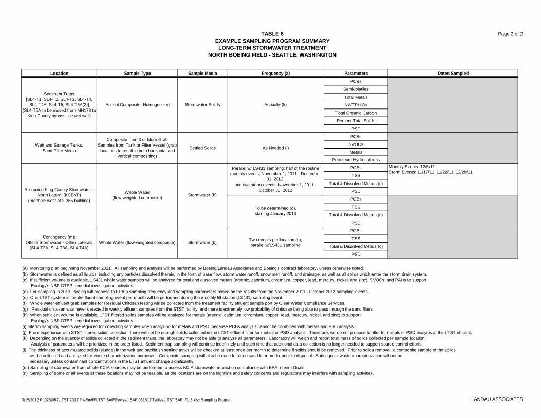
Lift Station (LS431)(Compliance Monitoring Point)
Whole Water(flow-weighted composite) Stormwater (b)
Monthly routine sampling(multiple day sampling period),
November 2011 - December 2012;Five additional 24-hour storm events of
≥0.5 inch precipitation,
November 1, 2011 - October 31, 2012
Monthly Events: 11/11/11, 12/8/11Storm Events: 11/17/11, 11/23/11, 12/28/11
TABLE 6 Page 2 of 2 EXAMPLE SAMPLING PROGRAM SUMMARY
LONG-TERM STORMWATER TREATMENT NORTH BOEING FIELD - SEATTLE, WASHINGTON
Location Sample Type Sample Media Frequency (a) Parameters Dates Sampled
Sediment Traps [SL4-T1, SL4-T2, SL4-T3, SL4-T4,
SL4-T4A, SL4-T5, SL4-T5A(2)] (SL4-T5A to be moved from MH178 to
King County bypass line wet well)
Annual Composite, Homogenized Stormwater Solids Annually (k)
PCBs
Semivolatiles
Total Metals
NWTPH-Dx
Total Organic Carbon
Percent Total Solids
PSD
Weir and Storage Tanks, Sand Filter Media
Composite from 3 or More Grab Samples from Tank or Filter Vessel (grab locations to result in both horizontal and
vertical compositing)
Settled Solids As Needed (l)
PCBs
SVOCs
Metals
Petroleum Hydrocarbons
Re-routed King County Stormwater -North Lateral (KCBYP)
(manhole west of 3-365 building)
Whole Water (flow-weighted composite) Stormwater (b)
Parallel w/ LS431 sampling: half of the routine monthly events, November 1, 2011 - December
31, 2012, and two storm events, November 1, 2011 -
October 31, 2012
PCBs Monthly Events: 12/5/11 Storm Events: 11/17/11, 11/22/11, 12/28/11
TSS
Total & Dissolved Metals (c)
PSD
To be determined (d), starting January 2013
PCBs
TSS
Total & Dissolved Metals (c)
PSD
Contingency (m): Offsite Stormwater - Other Laterals
(SL4-T2A, SL4-T3A, SL4-T4A) Whole Water (flow-weighted composite) Stormwater (b) Two events per location (n),
parallel w/LS431 sampling
PCBs
TSS
Total & Dissolved Metals (c)
PSD
(a) Monitoring plan beginning November 2011. All sampling and analysis will be performed by Boeing/Landau Associates and Boeing's contract laboratory, unless otherwise noted. (b) Stormwater is defined as all liquids, including any particles dissolved therein, in the form of base flow, storm water runoff, snow melt runoff, and drainage, as well as all solids which enter the storm drain system. (c) If sufficient volume is available, LS431 whole water samples will be analyzed for total and dissolved metals (arsenic, cadmium, chromium, copper, lead, mercury, nickel, and zinc); SVOCs; and PAHs to support Ecology's NBF-GTSP remedial investigation activities. (d) For sampling in 2013, Boeing will propose to EPA a sampling frequency and sampling parameters based on the results from the November 2011 - October 2012 sampling events. (e) One LTST system influent/effluent sampling event per month will be performed during the monthly lift station (LS431) sampling event. (f) Whole water effluent grab samples for Residual Chitosan testing will be collected from the treatment facility effluent sample port by Clear Water Compliance Services. (g) Residual chitosan was never detected in weekly effluent samples from the STST facility, and there is extremely low probability of chitosan being able to pass through the sand filters. (h) When sufficient volume is available, LTST filtered solids samples will be analyzed for metals (arsenic, cadmium, chromium, copper, lead, mercury, nickel, and zinc) to support Ecology's NBF-GTSP remedial investigation activities. (i) Interim sampling events are required for collecting samples when analyzing for metals and PSD, because PCBs analysis cannot be combined with metals and PSD analysis. (j) From experience with STST filtered solids collection, there will not be enough solids collected in the LTST effluent filter for metals or PSD analysis. Therefore, we do not propose to filter for metals or PSD analysis at the LTST effluent. (k) Depending on the quantity of solids collected in the sediment traps, the laboratory may not be able to analyze all parameters. Laboratory will weigh and report total mass of solids collected per sample location. Analysis of parameters will be prioritized in the order listed. Sediment trap sampling will continue indefinitely until such time that additional data collection is no longer needed to support source control efforts. (l) The thickness of accumulated solids (sludge) in the weir and backflush settling tanks will be checked at least once per month to determine if solids should be removed. Prior to solids removal, a composite sample of the solids
will be collected and analyzed for waste characterization purposes. Composite sampling will also be done for used sand filter media prior to disposal. Subsequent waste characterization will not be necessary unless contaminant concentrations in the LTST influent change significantly.
(m) Sampling of stormwater from offsite KCIA sources may be performed to assess KCIA stormwater impact on compliance with EPA Interim Goals. (n) Sampling of some or all events at these locations may not be feasible, as the locations are on the flightline and safety concerns and regulations may interfere with sampling activities.
3/15/2012 P:\025\082\LTST 2012\FileRm\R\LTST SAP\Revised SAP 031612\Tables\LTST SAP_Tb 6.xlsx Sampling Program LANDAU ASSOCIATES