Sample pages from Figures in the Fourth Dimension —...
16
3 This book is a combination volume— a lovingly designed art book, and a meticulously researched technical “teaching” book. It is 512 pages long, all in color, with hard cover and dust jacket. It has over 1500 illustrations: beautiful photographs of puppets and automata in action, and carefully detailed technical drawings of the mechanisms that make them move. The book contains work from three major museums, and over thirty world-class artists from all over the planet. The purpose of the book: to show how to build mechanical devices and linkages for puppets and automata, and introduce these techniques to a read- ership ranging from the beginner to the sophisticated artist-craftsman. To that end, the artists included in the book had to submit not only excellent quality photos of their pieces (preferably in several positions) but detailed drawings and diagrams showing how the pieces are actually built, and how they really work. In this pdf, you will see, first, the table of contents, listing everything to be found in the book, and then sample pages, showing the artworks, together with their technical photos and drawings. Because this pdf is meant as a sample only, to give you a good general idea of the book’s contents, it concentrates on a few representative pages from each section, and shows their major visual elements. Because of space constraints, the pdf eliminates some detailed text explanations and the extensive labeling of the drawings, which are present in the actual book. More information is at the book’s website, figuresinthefourthdimension.com. The book can be purchased at this website, and perhaps at a few other locations. To date, this website is probably the best place to find it. You can also email me at my personal email: [email protected]. Figures in the Fourth Dimension Mechanical Movement for Puppets and Automata Ellen S. Rixford Sample pages from Figures in the Fourth Dimension — as a pdf
Transcript of Sample pages from Figures in the Fourth Dimension —...
3
This book is a combination volume— a lovingly designed art book, and a meticulously researched technical “teaching” book. It is 512 pages long, all in color, with hard cover and dust jacket. It has over 1500 illustrations: beautiful photographs of puppets and automata in action, and carefully detailed technical drawings of the mechanisms that make them move. The book contains work from three major museums, and over thirty world-class artists from all over the planet. The purpose of the book: to show how to build mechanical devices and linkages for puppets and automata, and introduce these techniques to a read-ership ranging from the beginner to the sophisticated artist-craftsman. To that end, the artists included in the book had to submit not only excellent quality photos of their pieces (preferably in several positions) but detailed drawings and diagrams showing how the pieces are actually built, and how they really work. In this pdf, you will see, first, the table of contents, listing everything to be found in the book, and then sample pages, showing the artworks, together with their technical photos and drawings. Because this pdf is meant as a sample only, to give you a good general idea of the book’s contents, it concentrates on a few representative pages from each section, and shows their major visual elements. Because of space constraints, the pdf eliminates some detailed text explanations and the extensive labeling of the drawings, which are present in the actual book. More information is at the book’s website, figuresinthefourthdimension.com. The book can be purchased at this website, and perhaps at a few other locations. To date, this website is probably the best place to find it. You can also email me at my personal email: [email protected].
Figures in the Fourth DimensionMechanical Movement for Puppets and Automata
Ellen S. Rixford
Sample pages from Figures in the Fourth Dimension — as a pdf
4 5
About This Book and How to Use it................................................10Mechanics: Definitions and Principles............................................14Basic Mechanics................................................................................16 Power Sources Hand Cranks Motors ClockworkConnecting Power Sources to Mechanical Devices........................21 Strings, Cables, Rods, Rod Connectors Drive shafts, Cranks, and Crank Shafts Levers Linkages with Cranks and Levers Pulleys Sprocket Wheels and Chains Cams Pausing a Cam Movement Multiple Cams on One Shaft Changing Plane of Rotation — Friction Drives Followers Cams and Followers, Special Cases Gears and Gear-Related Ratchets and Pawls Geneva Wheels Bearings Springs Specialized Devices for Clockwork Automata: the Fusée The Plaque d’Animation Airflow — Bellows and Balloons Magnets Electrical Connections; Relays, SwitchesWorkspace, Tools, Materials............................................................62 The Workshop Power Tools Hand Tools and Supplies for Them Materials Resources and Suppliers’ ListSome Thoughts on Building.............................................................80
Table of ContentsPuppet Mechanisms (head and face)........................................................82 Punch and Judy; Kiyohime (Japanese Bunraku) maiden-to-monster A Collection of Monsters: Alice Wallace’s Moving Mouth in Hand Puppets Murgatroyd: foam head with all-directional rolling eyeballs and blinkersJim Kroupa...Hand-in-head and rod puppets, mechanical features.................94 Velvet Laambmore: eye blink Mouse: eyebrows and mouth Taxi Dog Eye movement, eye blink Eyebrows Tongue and teeth Ears Kroupa’s workshopPhillip Huber... Marionettes with mechanical features...........................112 Eduardo: Punk Rocker: construction, mouth mechanism Priscilla Pipes, Opera Singer: mouth mechanism, extending neck Pierrot, Tightrope Walker: specialized feet Oskar, Contortionist: control for specialized body movement Taffy, adorable iconic dog Nicole, nightclub Singer Mo Sho Long, or Magic Dragon, the Chinese Magician Magic wand, face change Butterflies from fan, puppet show, gold ball becomes Magician’s head Magician becomes smoke-breathing dragon; how “smoke” is doneJoseph Cashore...Marionettes with innovative controls..........................130 Xero, boy who climbs the puppeteer: loop device shortens strings Old Mike: homeless man, control for specialized human Mother and Baby: control for mother linked with sub-control for baby Primitive Man: specialized controls for fully prehensile hands Cyclone, the Horse: specialized control for bucking and rearing Elephant: specialized control for delicate movements, especially trunk Elephant: using magnets in his trunk and mouth to “eat” a fruitBill Nelson and Dan Lavender...Ventriloquist figures....................................162 Thurston: head fabrication, pivoting lower jaw, tongue, teeth Eye movement, eye blink Ear-flap Light-up nose The whole mechanism, plus head stick Torso: the “shrug” mechanism
Puppets and Puppeteers
Corbian Arts: Corbin Popp and Ian Carney...Lightwire puppets............180 All-over construction of the puppet costumes: dinosaurs, birds etcetera Lightwire or electroluminescent wire electronics diagrams Construction details, especially head, jaw
Ellen Rixford and Mayhew Lu...“Bunraku” puppets, “lighted” automata......192 Lady of the Inner Light and larger Fairy Queen Construction of inner light mechanism Door-opening mechanism Small Fairies: head turn, arm raise, wing flutter Goddess of Earth — Kind and Cruel Head mechanisms and control: eyes, mouth, head-split Goddess of Heaven — Kind and Cruel Head mechanism and control, interior light and color, masks Mechanical Hand: slider mechanism controls all five digits The Snow Queen Interior light mechanism for head, mask on/off Kay and Gerda mechanisms (children inside Snow Queen’s gown) Fairy in Silver Chafing Dish (and for Pearl, the Oyster Princess) Chafing Dish (Oyster) open/close cam and follower mechanism Fairy’s (Pearl’s) jointed “reverse marionette” mechanism
“Illuminated” Puppets — and Automata
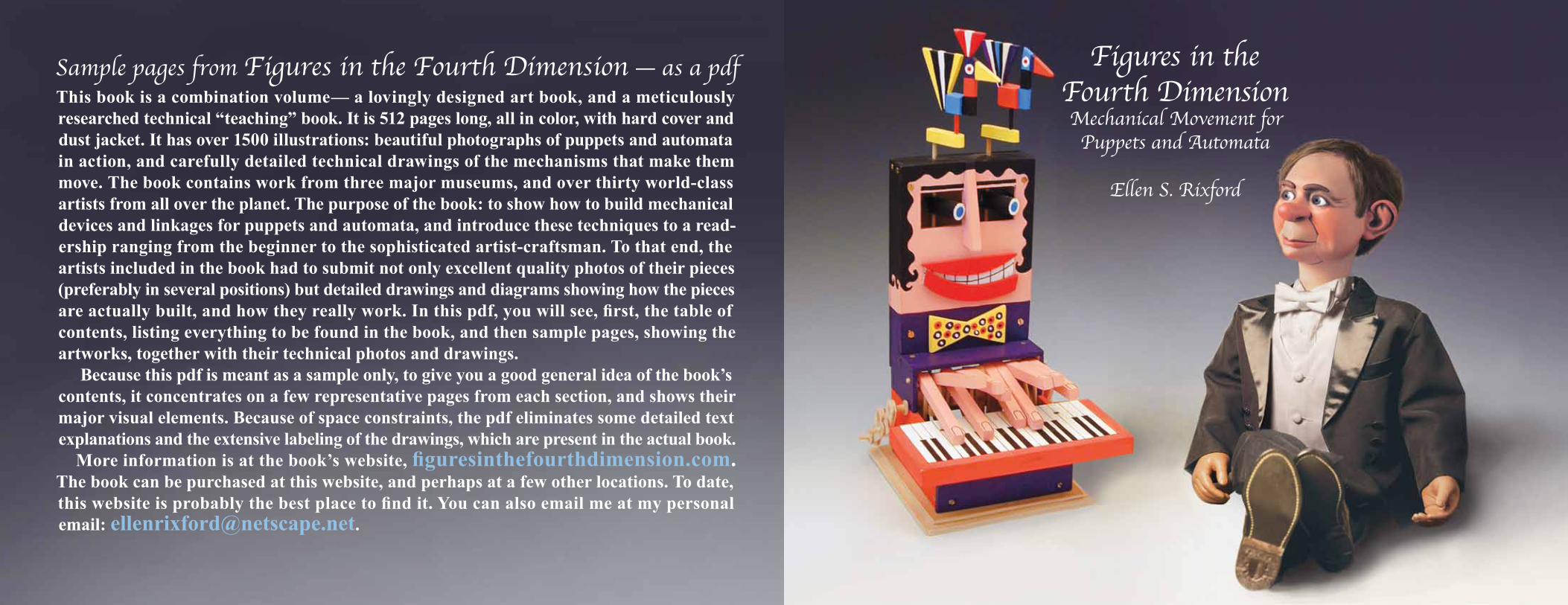
Diva, smoking chanteuse marionette by Phillip Huber: An LED at the end of the cigarette has two wires; one travels through the holder to the end, where a copper wire loop terminates at the mouthpiece. The second wire is threaded through the holder, through the hand, up the arm, through the shoulder and neck, into the head, where it connects to a 12-volt battery. The battery has a wire from the other end that terminates in a copper ring embedded in the Diva’s lip. When the end of the holder contacts the ring in the lip, a circuit is completed, the LED lights up, and the Diva takes a drag on her cigarette. 28" tall. Wood, Celastic, theatrical fabrics, wire, epoxy putty, sheet stainless steel, and brass tubing. 2015. Photos, the artist.
“Je ne regrette rien....!”The Basics.....For the Beginner......
6 7
Modern Automata: In this section, there are varying levels of difficulty. To make things easier, I suggest four levels. *= fairly easy to understand, **=moderately difficult, ***=complex, •=very complex.Peter Markey...Crank-operated automata in wood.................................230 *Big Wave Machine: multiple wave pattern cams, double crank *Piano, Rainbow, Birds and Clouds: friction drivesPablo Lavezzari...Crank-operated automata in wood, mixed media.......236 *Barracuda: crank, pulleys and belts *Utopia: space ship with waving wings, lit pilot light: pulleys and belts *Urban Face: head tilt, mouth open, pivoting eyes and brows, stand-up hair *Show Me Your Feelings: another face with similar movementsJan Zalud...Crank-operated automata in wood.......................................246 *Dog on Nose: offset cam, rocking see-saw type lever *Tour de Hat: 3D cams working eye, mouth movements; spinning cyclist *Sleepless: gears, ratchet, pulley creates eye movement; tiny running sheep *Your Turn: alternately moving eyes and mouths of two facesWanda Sowry...Crank-operated automata in wood..................................254 *Self-portrait: miniature crankshaft within a crankshaft *Here Be Monsters: crankshaft, rocker bars power giant squid
Dominique Corbin...Crank-operated automata in wood, mixed media.......258 *Potato Eater: rotating pin plus wooden potato activates wavy levers *Cow: multiple shaped cams, levers, “moo” box, cowbellLee Daunno...Coin-op automata; small figures, music box mechanisms.......262 *Hurdy-gurdy player automata, large figures, basic mechanisms Coin-op diagram of electrical connections *Musical movement mechanisms for small wooden automataEric Williamson...Crank-operated wooden automata sold as DIY kits..........266 *Stephenson’s Rocket: locomotive; double cranks, connecting arms *Kissing Couple: double friction drive *Drummer: multiple cams play multiple drums and cymbals *Pianist: multiple cams move piano keys, thus pianist’s fingersKeith Newstead...Crank-operated automata in wood, mixed media.....274 *Flying Pig: multiple pulleys and belts create flying machine *Mermaid: multiple pulleys and belts make her swim undulatingly *Dragon: “flies” via pulleys, cables, rods, curved wire body core *Icarus Flies Undone: Greek aeronaut, open underpants; crank slider **Mary, Queen of Scots: grisly execution, multiple camsWalter Einsel...Crank and motor-operated automata, wood, mixed media...284 *Grandfather Clock: wooden man with inset clock mechanisms *Nixon Washes His Dirty Laundry in Public: uses old fashioned mangle *Paradise Costs: turntable-operated doublefaced Adam and Eve *Man with Rolling Eyes: rack and pinion rotates eyes, lifts bowler hat **Man Holding Hat: shake his hand, head falls off, pants fall down *Wheel Ballerina: high kicks when wheel supporting her body is spunTom Haney...Motor-driven mixed media and found object automata .........292 *Undaunted: flying man, motor-driven propeller *Crescendo: two multi-lobed cams plus four levers equals piano concert **Lauren & Jordan: dentists’ children on giant molar: cams, rocker bar *Balinese Dancer: marionette powered by multiple cams and levers *Contraption: cams, pulleys, belts make useless but fun machine **Wanderlust: man with globe; three interconnected motors, pulleysNeil Hardy...Crank-operated mostly wood automata....................................300 **The Early Bird Nearly Catches It: bird mistakes tiger’s tail for worm Tiger mechanism: separate body parts moved by complex cam Speech bubbles for birds: multiple cams and followers Door opener mechanism: cam-operated complex multi-pivot hinging *Growler: newspaper-reading dog howls at moonrise Dog parts pivot on spring wire; moon operated via crank slider. *Great Tongue: pulleys and belt operate extremely long rubber tongue
**Survival of the Fittest: four species plus human exhibited via Geneva Wheel Geneva wheel, (or cross’s) interaction with crank handle, main gear Rotation of core inner section; relationship with Geneva cross Linkages for Cheetah, Crocodile, Gorilla, Whale — all on same shaft Cabinet door opener: via five-pointed Geneva star, two cams Beer-drinking man mechanism: cables and bent rods Detailed analysis of Geneva cross action through program *Evolutionary Blunder: colorful child penguin shocks Mama Penguin wings: twin bent rods rotated by cables from cam Mother penguin keels over: string from cam; spring returnRon Fuller...Crank-operated automata in mixed media..........................332 *Sheep Shearing Man: Large laughing sheep decapitates small man Action sequence, diagrams Closeups of the mechanic’s parts •Lion Lepidoptera: Mischievous butterfly teases dozing lion All-over diagram, all parts and interaction Closeups of parts, wire-wrap clutch Views of actual mechanicsPaul Spooner...crank and motor-operated mixed media automata.............346 *Borgia’s Cat: (alias “Poisoned Milk”) cat laps milk, keels over Sequential photos, diagrams of construction and operation **Bureau Automatique: government functionary, reappearing documents Bellows-activated mechanism, description and drawing **Little Multiplier: child learns multiplication from giant numbered prism Mechanisms & drawing: helicoid cam turns prism. *Woman in Armchair: woman as chair; chair arms have moving fingers Explanatory photo of mechanism, labeled to show function
***Untitled: nude woman, body sections open to show various dramas Details of back of automaton, mechanisms, circuitry in view Complete sequenced views of automaton’s circuitry Motor and pinwheel gears for main movements Mechanics for activities inside thighs, midriff, breasts Closeup photos of mechanical parts; office workers inside thighs Climbing men/jackals in midriff; lawn mowing jackals in breasts Inside head: Jackal making toastDavid Archer...Coin-op mixed media fortune-telling automata...................372 **Skull of Truth: your fortune plus thunder, demonic laughter Construction details; how coin-op works Brain wheel, Fortune wheel, electronic diagram *A Journey Into the Mind: peep-hole view of “brain contents”
Chris Fitch...motorized automata, some electronics..........................................378 **Sigh: brass/cast bronze sighing orchid with segmented parts Construction explained Construction diagrammed; crankshaft inside pot; motorized bellows unit **Spring: Giant furling and unfurling fern frond, with sequenced links Construction explained Latching relay circuit, shutoff switch actuator diagrammed Construction and action of sequenced links in detail **Tantalus Mackerel: hapless fish vainly snaps at bug Whole mechanism, sprocket and chain drives, levers Closeups of mechanism, explanation of partsMichael Curry...motorized electronically operated mechanical sculpture.........398 •Trash Phoenix: trashcan transforms into giant bird; description Sequential views, trashcan metamorphosing into phoenix Structural and electrical/electronic diagrams
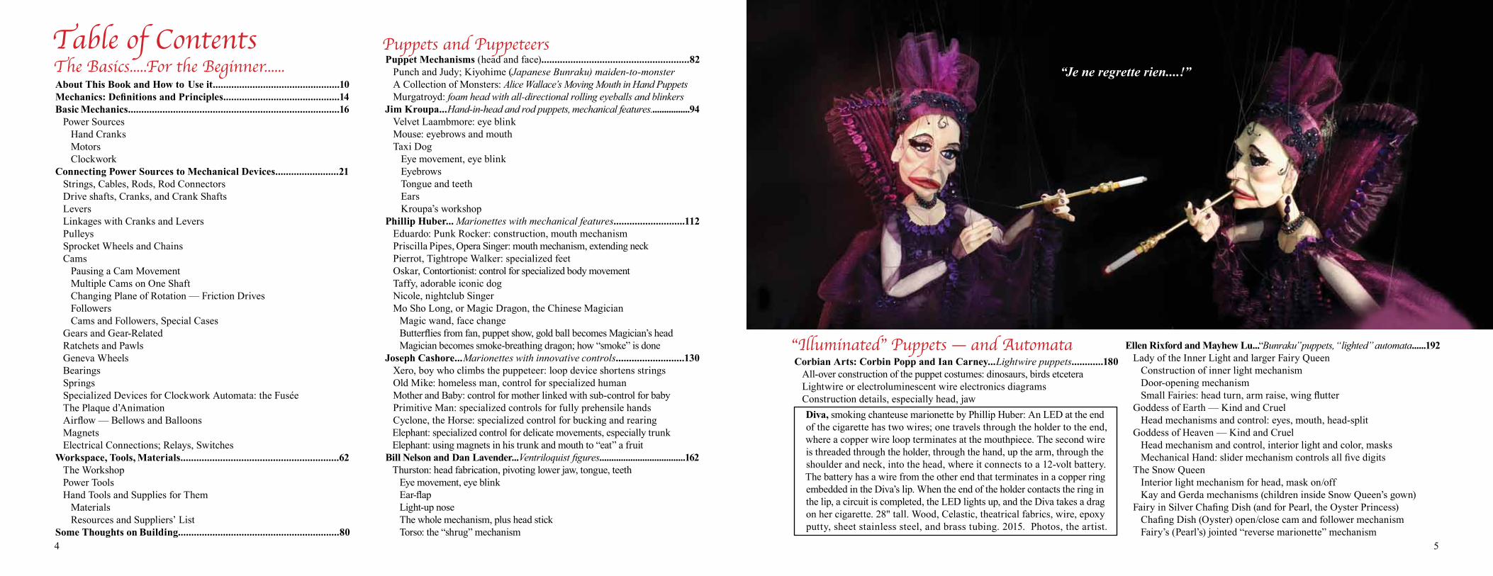
Vintage Training Robotic Arm, by Pablo Lavezzari. 45" x 23" x 30". Wood, glass, copper, bronze, paper. 2014. For
private collector. Photo, the artist.
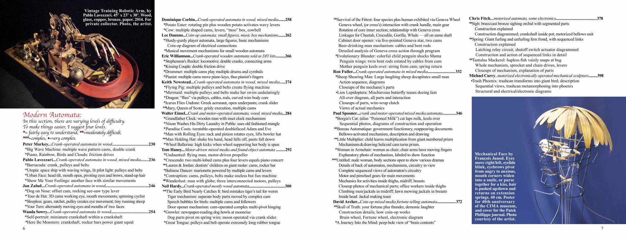
Mechanical Face by François Junod. Eyes move right/left, eyelids blink, eyebrows pivot from angry to anxious, mouth corners widen into a smile, or purse together for a kiss, hair is pushed up/down and returns on extension springs. 40 cm. Poster for 40th anniversary of the CIMA museum, and cover for the Patek Phillippe journal. Photo courtesy of the artist.
8 9
Henri Maillardet...18th Century writing and drawing android..........466 ••Boy Artist and Poet: four lovely drawings, three charming poems The pictures and poems Plan view of machine; section view, cams-to-linkages Views from either end of machine Power transmission system: mainsprings-to-fan-bladed governors Information system: program cams and their followers Program cams and right arm mechanisms, photos Linkages: forward/back, side/side, up/down right hand movement Linkages: head and left hand movement Program Selection System and Power System relationships Program Selection System, exploded view, all components Photo of costumed automaton as originally exhibited Details of automaton performance François Junod...special section modern Golden Age automatier...............502 The poetry written by the automaton, choice of vocabulary General Construction of the machine The three motors in the machine, and their roles, with labeled photos A selection of technical drawings of various parts of the machine: Elevator mechanism to raise and lower program cams Multi-level cams for regulating movement of other cams Random selection disk for selecting the words, pictures, for the poems Wheels and levers operating the random selectionBook List..........................................................................................................508 Books on Puppetry Books on Automata and Related Mechanisms Books on Antique and Historical Automata Japanese book on Traditional Karakuri Ningyo Books on Modern Automata Books on Mechanisms and Mechanical DevicesGuide to Websites and Videos....(ebibliography).........................................511 “Golden Age” Automata Collections Puppet and Automata websites and/or videos for artists in the book
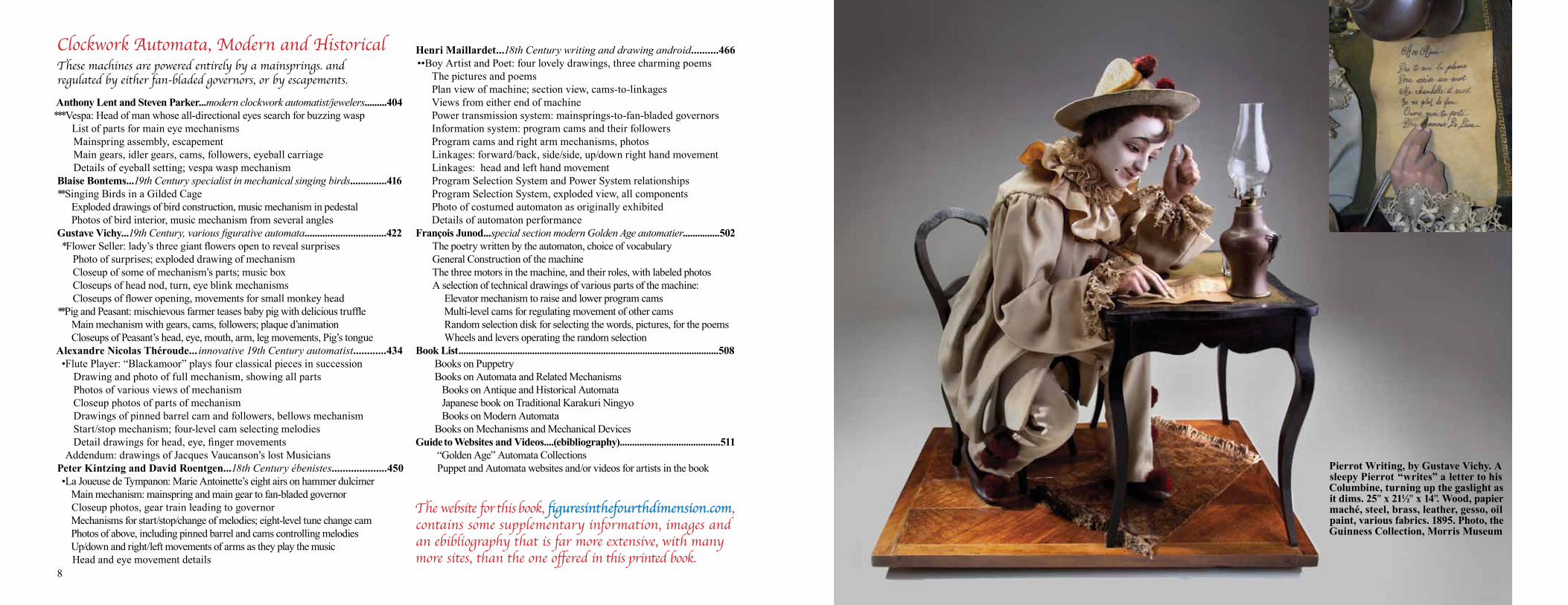
Anthony Lent and Steven Parker...modern clockwork automatist/jewelers.........404***Vespa: Head of man whose all-directional eyes search for buzzing wasp List of parts for main eye mechanisms Mainspring assembly, escapement Main gears, idler gears, cams, followers, eyeball carriage Details of eyeball setting; vespa wasp mechanismBlaise Bontems...19th Century specialist in mechanical singing birds..............416 **Singing Birds in a Gilded Cage Exploded drawings of bird construction, music mechanism in pedestal Photos of bird interior, music mechanism from several anglesGustave Vichy...19th Century, various figurative automata................................422 *Flower Seller: lady’s three giant flowers open to reveal surprises Photo of surprises; exploded drawing of mechanism Closeup of some of mechanism’s parts; music box Closeups of head nod, turn, eye blink mechanisms Closeups of flower opening, movements for small monkey head **Pig and Peasant: mischievous farmer teases baby pig with delicious truffle Main mechanism with gears, cams, followers; plaque d’animation Closeups of Peasant’s head, eye, mouth, arm, leg movements, Pig’s tongueAlexandre Nicolas Théroude... innovative 19th Century automatist............434 •Flute Player: “Blackamoor” plays four classical pieces in succession Drawing and photo of full mechanism, showing all parts Photos of various views of mechanism Closeup photos of parts of mechanism Drawings of pinned barrel cam and followers, bellows mechanism Start/stop mechanism; four-level cam selecting melodies Detail drawings for head, eye, finger movements Addendum: drawings of Jacques Vaucanson’s lost MusiciansPeter Kintzing and David Roentgen...18th Century ébenistes....................450 •La Joueuse de Tympanon: Marie Antoinette’s eight airs on hammer dulcimer Main mechanism: mainspring and main gear to fan-bladed governor Closeup photos, gear train leading to governor Mechanisms for start/stop/change of melodies; eight-level tune change cam Photos of above, including pinned barrel and cams controlling melodies Up/down and right/left movements of arms as they play the music Head and eye movement details
Clockwork Automata, Modern and HistoricalThese machines are powered entirely by a mainsprings. and regulated by either fan-bladed governors, or by escapements.
Pierrot Writing, by Gustave Vichy. A sleepy Pierrot “writes” a letter to his Columbine, turning up the gaslight as it dims. 25" x 21½" x 14". Wood, papier maché, steel, brass, leather, gesso, oil paint, various fabrics. 1895. Photo, the Guinness Collection, Morris Museum
The website for this book, figuresinthefourthdimension.com, contains some supplementary information, images and an ebibliography that is far more extensive, with many more sites, than the one offered in this printed book.
10 11
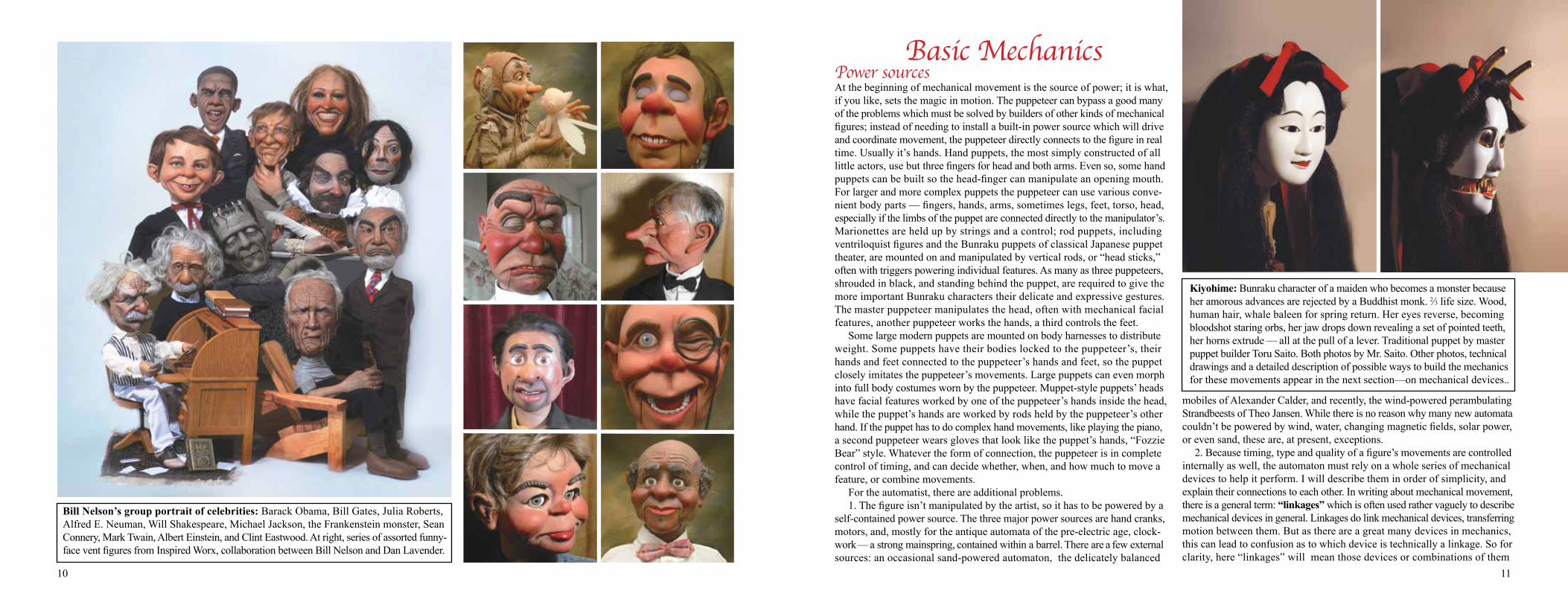
Bill Nelson’s group portrait of celebrities: Barack Obama, Bill Gates, Julia Roberts, Alfred E. Neuman, Will Shakespeare, Michael Jackson, the Frankenstein monster, Sean Connery, Mark Twain, Albert Einstein, and Clint Eastwood. At right, series of assorted funny-face vent figures from Inspired Worx, collaboration between Bill Nelson and Dan Lavender.
Basic MechanicsPower sourcesAt the beginning of mechanical movement is the source of power; it is what, if you like, sets the magic in motion. The puppeteer can bypass a good many of the problems which must be solved by builders of other kinds of mechanical figures; instead of needing to install a built-in power source which will drive and coordinate movement, the puppeteer directly connects to the figure in real time. Usually it’s hands. Hand puppets, the most simply constructed of all little actors, use but three fingers for head and both arms. Even so, some hand puppets can be built so the head-finger can manipulate an opening mouth. For larger and more complex puppets the puppeteer can use various conve-nient body parts — fingers, hands, arms, sometimes legs, feet, torso, head, especially if the limbs of the puppet are connected directly to the manipulator’s. Marionettes are held up by strings and a control; rod puppets, including ventriloquist figures and the Bunraku puppets of classical Japanese puppet theater, are mounted on and manipulated by vertical rods, or “head sticks,” often with triggers powering individual features. As many as three puppeteers, shrouded in black, and standing behind the puppet, are required to give the more important Bunraku characters their delicate and expressive gestures. The master puppeteer manipulates the head, often with mechanical facial features, another puppeteer works the hands, a third controls the feet. Some large modern puppets are mounted on body harnesses to distribute weight. Some puppets have their bodies locked to the puppeteer’s, their hands and feet connected to the puppeteer’s hands and feet, so the puppet closely imitates the puppeteer’s movements. Large puppets can even morph into full body costumes worn by the puppeteer. Muppet-style puppets’ heads have facial features worked by one of the puppeteer’s hands inside the head, while the puppet’s hands are worked by rods held by the puppeteer’s other hand. If the puppet has to do complex hand movements, like playing the piano, a second puppeteer wears gloves that look like the puppet’s hands, “Fozzie Bear” style. Whatever the form of connection, the puppeteer is in complete control of timing, and can decide whether, when, and how much to move a feature, or combine movements. For the automatist, there are additional problems. 1. The figure isn’t manipulated by the artist, so it has to be powered by a self-contained power source. The three major power sources are hand cranks, motors, and, mostly for the antique automata of the pre-electric age, clock-work — a strong mainspring, contained within a barrel. There are a few external sources: an occasional sand-powered automaton, the delicately balanced
mobiles of Alexander Calder, and recently, the wind-powered perambulating Strandbeests of Theo Jansen. While there is no reason why many new automata couldn’t be powered by wind, water, changing magnetic fields, solar power, or even sand, these are, at present, exceptions. 2. Because timing, type and quality of a figure’s movements are controlled internally as well, the automaton must rely on a whole series of mechanical devices to help it perform. I will describe them in order of simplicity, and explain their connections to each other. In writing about mechanical movement, there is a general term: “linkages” which is often used rather vaguely to describe mechanical devices in general. Linkages do link mechanical devices, transferring motion between them. But as there are a great many devices in mechanics, this can lead to confusion as to which device is technically a linkage. So for clarity, here “linkages” will mean those devices or combinations of them
Kiyohime: Bunraku character of a maiden who becomes a monster because her amorous advances are rejected by a Buddhist monk. 2⁄3 life size. Wood, human hair, whale baleen for spring return. Her eyes reverse, becoming bloodshot staring orbs, her jaw drops down revealing a set of pointed teeth, her horns extrude — all at the pull of a lever. Traditional puppet by master puppet builder Toru Saito. Both photos by Mr. Saito. Other photos, technical drawings and a detailed description of possible ways to build the mechanics for these movements appear in the next section—on mechanical devices..
12 13
If the drive shaft has bends in it, it becomes a crank shaft. When the drive shaft ends in a bend with a handle on the end of it, that is a crank handle, powering the automaton. Cranks and crank shafts are normally used when one wants to change direction from rotating to reciprocal motion — back and forth, side to side, or up and down. The bigger the bend in a crank shaft, the bigger the reciprocal motion. Cranks can be bent rods; crank shafts can be bent rods or combinations of rods, straight and/or bent. The bends are not always straight 90° angles, either. Curved or wavy bends (often made with wire) can result in a beautiful reciprocating wavy movement, like surf in a mechanical seascape, or the writhing of a mechanical snake or dragon. Cranks can be power sources, or links which transfer power to something else They can change the direction, dimension, and effort needed for a movement. When the crank is used as a lever turning the drive shaft, the length of its handle increases force or torque, making it easier to rotate the automaton’s drive shaft. Many automata, even quite complex ones, are hand cranked. Nearly all automata contain some form of crank or crankshaft within their mechanics. And cranks and crank shafts offer many possibilities to the puppeteer, who can rotate a pair of eyeballs, raise or lower eyebrows, or swing open a pivoting jaw by connecting these linkages to cranks plus push-pull rods or pull-cables inside the puppet’s head.
LeversLevers are pivoted rods; the pivot here is called the lever’s fulcrum. They appear in nearly every automaton, and in many puppet mechanics as well. They can help marionettists by vastly extending the “reach” of a movement on a control; they often serve the automatist as “rider-followers,” transmitting motion from one device to another. Most often they are straight, but can also be bent; in French they are called a “levier coudé” or “elbowed” lever and in English, a bell crank, illustrated in the following pages. As discussed below, a bent lever or bell crank will, instead of moving something at a 180° angle, move it at a differ-ent angle, depending on the angle of the bend. It can also change distances. There are three types, or classes, of levers. A class one lever consists of a bar with the pivot point or fulcrum in the middle, the force moving the bar at one end and the load, or weight of something to be moved, at the other. When the force applied and load are equal, or perfectly balanced, that is equilibrium — no change in movement. When either the force or the load increases or decreases, equilibrium is lost; there is movement. Levers can vary the relationship between the force needed to move a load and the weight of the load, depending on the placement of the fulcrum. Using a lever, and placing the fulcrum or pivot appropriately, a small force can move a very large load. A longer distance between the fulcrum and the force and a correspond-ingly short distance between fulcrum and load proportionally increases the mechanical advantage, or the ratio of load/force. The greater the distance the greater the weight or number of units of load that can be moved by one unit of force. And vice versa. Examples of class one levers: children’s see-saws, a long crowbar prying up a heavy rock; scissors, pliers, bolt cutters where the hinge is the fulcrum, the material being cut or squeezed is the load, and the force is the hand. A class two lever has the fulcrum at one end, the load in the middle, and the force at the opposite end. Because in this configuration the distance between the fulcrum and the force must be longer than the distance between the fulcrum and the load, this kind of lever always results in positive mechanical advantage, less force moving more of a load. This kind of lever is useful for devices needing to greatly lessen the force needed to move a given load: nutcrackers, wheelbarrows. A Class three lever also has the fulcrum at one end, but the force is in the middle and the load is at the end. Here the distance between the fulcrum and the force is shorter, resulting in a mechanical advantage of less than one. This kind of lever is useful if not much force, but greater precision is required; example: a pair of tweezers. Class one and class two levers are very frequently used as followers in automata, and often appear as part of puppet mechanics and controls as well. Class three levers appear less often, but can be useful when one wants to “step down” the level of force for a very small, delicate movement.
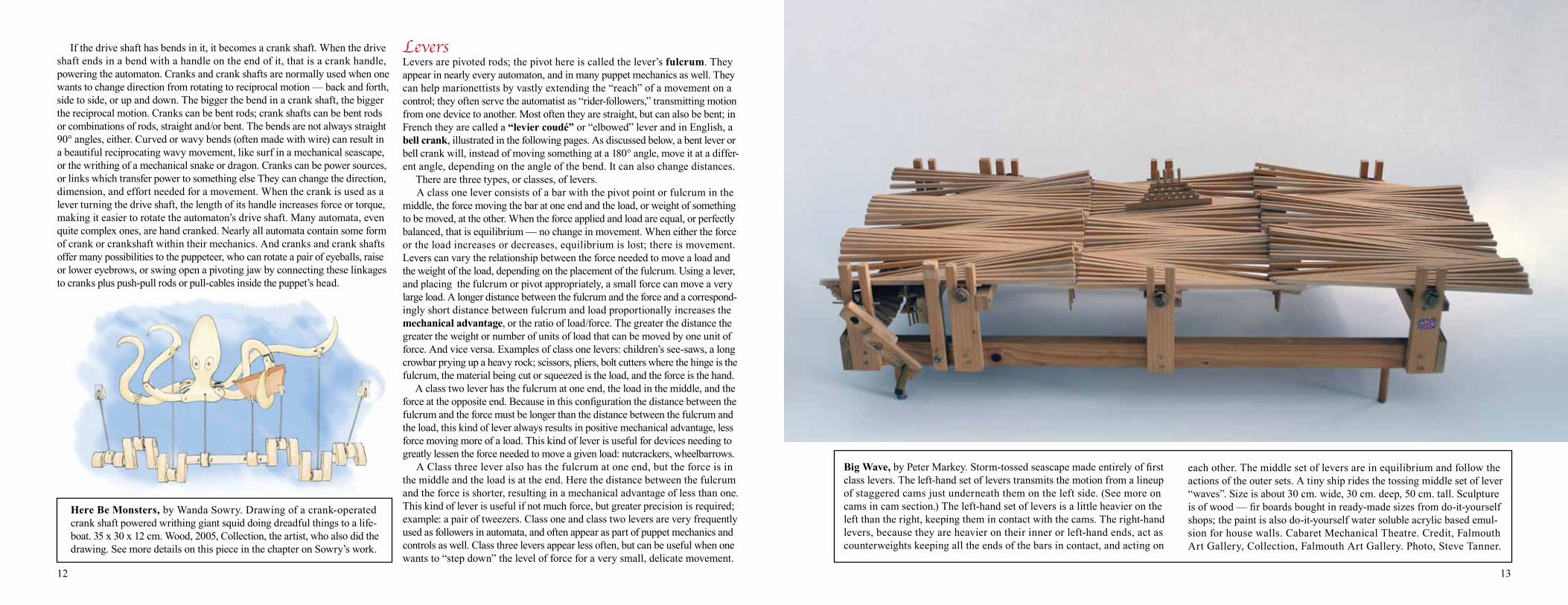
Big Wave, by Peter Markey. Storm-tossed seascape made entirely of first class levers. The left-hand set of levers transmits the motion from a lineup of staggered cams just underneath them on the left side. (See more on cams in cam section.) The left-hand set of levers is a little heavier on the left than the right, keeping them in contact with the cams. The right-hand levers, because they are heavier on their inner or left-hand ends, act as counterweights keeping all the ends of the bars in contact, and acting on
each other. The middle set of levers are in equilibrium and follow the actions of the outer sets. A tiny ship rides the tossing middle set of lever “waves”. Size is about 30 cm. wide, 30 cm. deep, 50 cm. tall. Sculpture is of wood — fir boards bought in ready-made sizes from do-it-yourself shops; the paint is also do-it-yourself water soluble acrylic based emul-sion for house walls. Cabaret Mechanical Theatre. Credit, Falmouth Art Gallery, Collection, Falmouth Art Gallery. Photo, Steve Tanner.
Here Be Monsters, by Wanda Sowry. Drawing of a crank-operated crank shaft powered writhing giant squid doing dreadful things to a life-boat. 35 x 30 x 12 cm. Wood, 2005, Collection, the artist, who also did the drawing. See more details on this piece in the chapter on Sowry’s work.
14 15
They are wheels connected to other wheels via belts. The wheels can be made of any hard material (for example, wood, plastic, metal) and the belts can be any strong and flexible connector (for example, leather, nylon or rubber). One wheel turns the other due to the friction generated by the belt rubbing over the wheel edge and pulling it around. Thus, pulleys are classified as friction drives. The wheels can have various kinds of edges — most often concave rims at the wheel edge or a simple groove to hold the belt, increase friction, and keep it from slipping off. A common use for pulleys in automata and pup-petry is transmitting rotational movement from one part of the piece to another part, or to several other parts. A primary pulley wheel on a drive shaft, rotated by the crank that powers the automaton, can be connected via one or several wheel and belt combinations to secondary wheels or shafts in other parts of the piece, causing many parts to rotate at once. If the pulley wheels are of different sizes, they rotate at varying speeds. If the pulley wheel at the beginning of the sequence is a large diameter one, say one foot, and the wheel (or shaft) belted to it is smaller, say, one-fourth the diameter, or three inches, one rotation of the first pulley will result in four rotations of the smaller one. In ALL rotating devices: pulleys, friction drives, gears, increasing the rpm speed of any wheel-related device proportionally decreases force; decreasing speed increases force. In automata, this is a major consideration. Some parts of a mechanical movement need to turn with more force to power heavy mechanical devices. Other parts need a very light force so they can be easily braked.
Pulleys
CamsWhile the crank and shaft give fairly simple reciprocal movements, the cam offers possibilities for more complex movements, with more variety. Cams are disks, usually but not always two-dimensional, whose shapes or profiles modify movement as they rotate. They are used to control the nature and timing of movement. Cam profiles can come in any number of variations. The simplest are eccentric or off-center cams — a disk with an eccentric center pivot. Then come egg-shaped, heart-shaped, and multi-lobed shapes, sometimes called daisy cams because their shape reminds one of flower petals; and the so-called nautilus or snail cam, because of its resemblance to the shell. The nautilus cam has a gradually rising profile which suddenly drops back to the point nearest the center. If you measure the distances between a cam’s center pivot point, and the cam’s edges, you will get the throw of the cam. It is the difference between the shortest distance pivot-to-edge, and the longest distance pivot-to-edge. This would be the distance something attached to or resting on the cam would travel back and forth as the cam rotates. In the case of the eccentric circle, egg-shape or oval shape, the distance gradually increases and decreases in a regular pat-tern. The eccentric circle and egg-shaped type of cam will give gradual move-ments from one point to another — one cycle per revolution of the cam: an arm rising and falling, a head or body turning, wings unfolding and folding, a box or a door opening and closing, a mask removed and replaced. The nautilus cam’s profile results in a gradual movement in one direction followed by a very sudden movement in the other: an executioner raising his axe and suddenly bringing it down to chop off a head, or a lion snapping off the head of a circus performer. This kind of cam can also be used as a switching mechanism. Another very simple switching device is a disk cam with a little “bite” taken out of it. Multi- lobed profiles result in many movements back and forth per cam revolution.
dwell area
dwell areain green
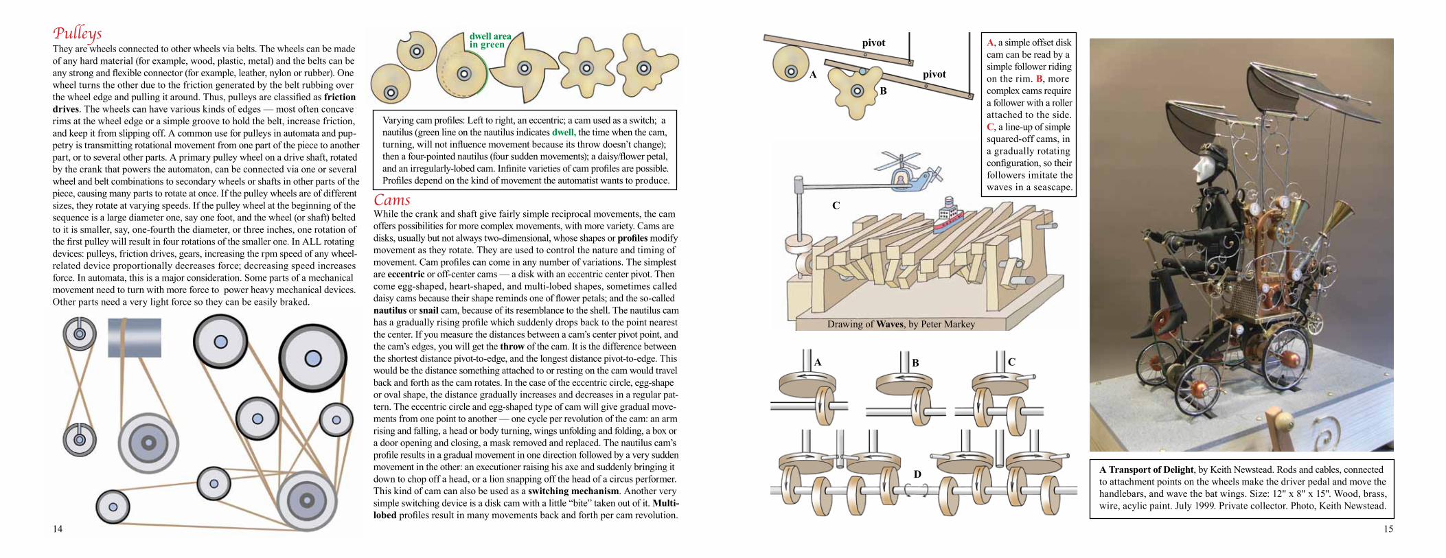
Varying cam profiles: Left to right, an eccentric; a cam used as a switch; a nautilus (green line on the nautilus indicates dwell, the time when the cam, turning, will not influence movement because its throw doesn’t change); then a four-pointed nautilus (four sudden movements); a daisy/flower petal, and an irregularly-lobed cam. Infinite varieties of cam profiles are possible. Profiles depend on the kind of movement the automatist wants to produce.
A Transport of Delight, by Keith Newstead. Rods and cables, connected to attachment points on the wheels make the driver pedal and move the handlebars, and wave the bat wings. Size: 12" x 8" x 15". Wood, brass, wire, acylic paint. July 1999. Private collector. Photo, Keith Newstead.
A, a simple offset disk cam can be read by a simple follower riding on the rim. B, more complex cams require a follower with a roller attached to the side. C, a line-up of simple squared-off cams, in a gradually rotating configuration, so their followers imitate the waves in a seascape.
AB
pivot
pivot
C
Drawing of Waves, by Peter Markey
A B C
D
16 17
Gears and Gear-related
Sp
Rk
C
P
Bv
Bv' Bv"
Bvm
Wm
Sp
Wms
Rk
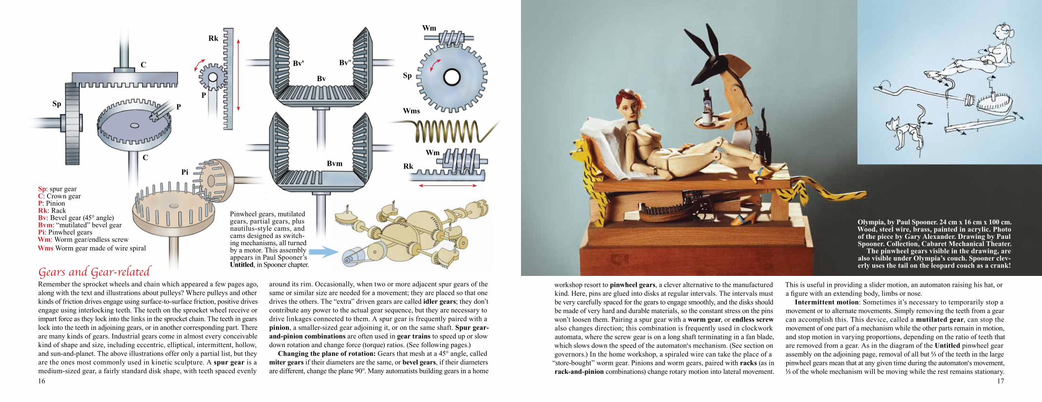
Sp: spur gearC: Crown gearP: PinionRk: RackBv: Bevel gear (45° angle)Bvm: “mutilated” bevel gearPi: Pinwheel gearsWm: Worm gear/endless screwWms Worm gear made of wire spiral
C
P
Pi
Remember the sprocket wheels and chain which appeared a few pages ago, along with the text and illustrations about pulleys? Where pulleys and other kinds of friction drives engage using surface-to-surface friction, positive drives engage using interlocking teeth. The teeth on the sprocket wheel receive or impart force as they lock into the links in the sprocket chain. The teeth in gears lock into the teeth in adjoining gears, or in another corresponding part. There are many kinds of gears. Industrial gears come in almost every conceivable kind of shape and size, including eccentric, elliptical, intermittent, hollow, and sun-and-planet. The above illustrations offer only a partial list, but they are the ones most commonly used in kinetic sculpture. A spur gear is a medium-sized gear, a fairly standard disk shape, with teeth spaced evenly
around its rim. Occasionally, when two or more adjacent spur gears of the same or similar size are needed for a movement; they are placed so that one drives the others. The “extra” driven gears are called idler gears; they don’t contribute any power to the actual gear sequence, but they are necessary to drive linkages connected to them. A spur gear is frequently paired with a pinion, a smaller-sized gear adjoining it, or on the same shaft. Spur gear-and-pinion combinations are often used in gear trains to speed up or slow down rotation and change force (torque) ratios. (See following pages.) Changing the plane of rotation: Gears that mesh at a 45° angle, called miter gears if their diameters are the same, or bevel gears, if their diameters are different, change the plane 90°. Many automatists building gears in a home
Olympia, by Paul Spooner. 24 cm x 16 cm x 100 cm.Wood, steel wire, brass, painted in acrylic. Photo of the piece by Gary Alexander. Drawing by Paul Spooner. Collection, Cabaret Mechanical Theater. The pinwheel gears visible in the drawing, are also visible under Olympia’s couch. Spooner clev-erly uses the tail on the leopard couch as a crank!
workshop resort to pinwheel gears, a clever alternative to the manufactured kind. Here, pins are glued into disks at regular intervals. The intervals must be very carefully spaced for the gears to engage smoothly, and the disks should be made of very hard and durable materials, so the constant stress on the pins won’t loosen them. Pairing a spur gear with a worm gear, or endless screw also changes direction; this combination is frequently used in clockwork automata, where the screw gear is on a long shaft terminating in a fan blade, which slows down the speed of the automaton‘s mechanism. (See section on governors.) In the home workshop, a spiraled wire can take the place of a
“store-bought” worm gear. Pinions and worm gears, paired with racks (as in rack-and-pinion combinations) change rotary motion into lateral movement.
This is useful in providing a slider motion, an automaton raising his hat, or a figure with an extending body, limbs or nose. Intermittent motion: Sometimes it’s necessary to temporarily stop a movement or to alternate movements. Simply removing the teeth from a gear can accomplish this. This device, called a mutilated gear, can stop the movement of one part of a mechanism while the other parts remain in motion, and stop motion in varying proportions, depending on the ratio of teeth that are removed from a gear. As in the diagram of the Untitled pinwheel gear assembly on the adjoining page, removal of all but 1⁄3 of the teeth in the large pinwheel gears mean that at any given time during the automaton‘s movement, 1⁄3 of the whole mechanism will be moving while the rest remains stationary.
Pinwheel gears, mutilated gears, partial gears, plus nautilus-style cams, and cams designed as switch-ing mechanisms, all turned by a motor. This assembly appears in Paul Spooner’s Untitled, in Spooner chapter.
Wm
34 35
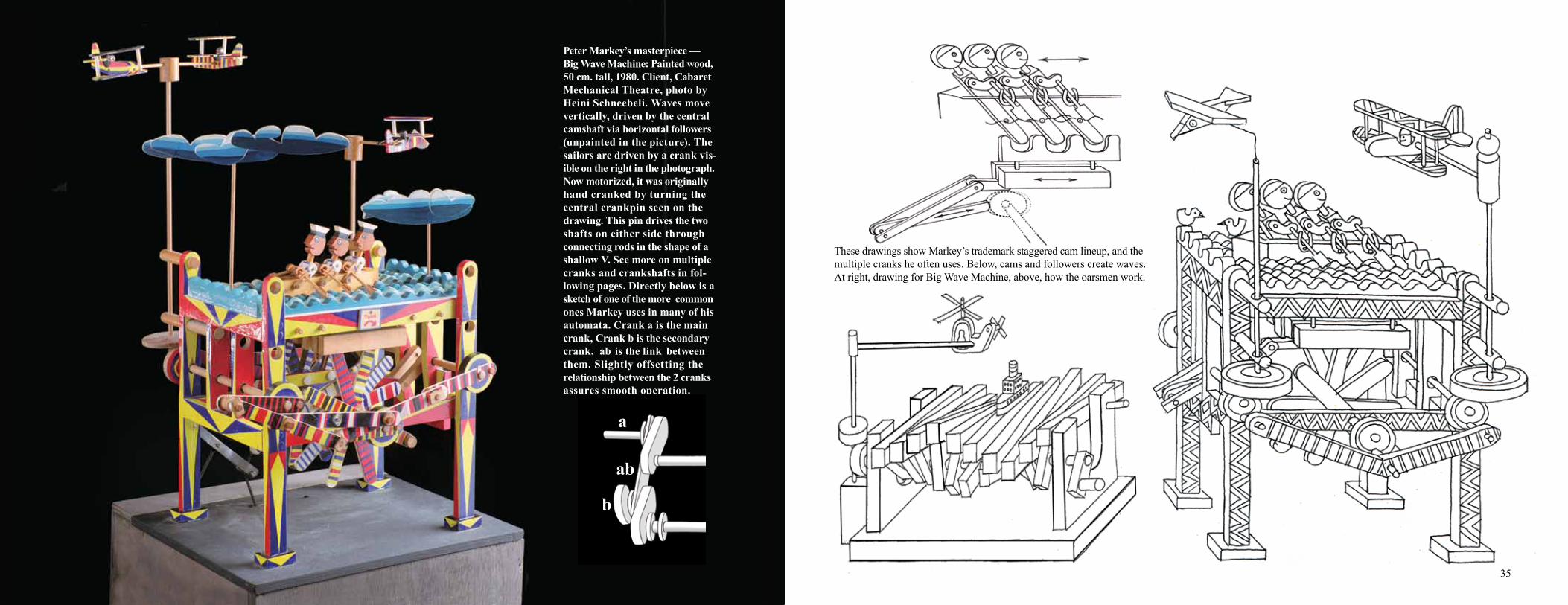
Peter Markey’s masterpiece —Big Wave Machine: Painted wood, 50 cm. tall, 1980. Client, Cabaret Mechanical Theatre, photo by Heini Schneebeli. Waves move vertically, driven by the central camshaft via horizontal followers (unpainted in the picture). The sailors are driven by a crank vis-ible on the right in the photograph. Now motorized, it was originally hand cranked by turning the central crankpin seen on the drawing. This pin drives the two shafts on either side through connecting rods in the shape of a shallow V. See more on multiple cranks and crankshafts in fol-lowing pages. Directly below is a sketch of one of the more common ones Markey uses in many of his automata. Crank a is the main crank, Crank b is the secondary crank, ab is the link between them. Slightly offsetting the relationship between the 2 cranks assures smooth operation.
a
ab
b
C
These drawings show Markey’s trademark staggered cam lineup, and the multiple cranks he often uses. Below, cams and followers create waves. At right, drawing for Big Wave Machine, above, how the oarsmen work.
36 37
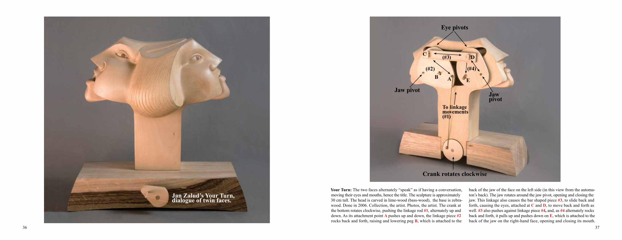
Your Turn: The two faces alternately “speak” as if having a conversation, moving their eyes and mouths, hence the title. The sculpture is approximately 30 cm tall. The head is carved in lime-wood (bass-wood), the base is zebra-wood. Done in 2006. Collection, the artist. Photos, the artist. The crank at the bottom rotates clockwise, pushing the linkage rod #1, alternately up and down. As its attachment point A pushes up and down, the linkage piece #2 rocks back and forth, raising and lowering peg B, which is attached to the
back of the jaw of the face on the left side (in this view from the automa-ton’s back). The jaw rotates around the jaw pivot, opening and closing the jaw. This linkage also causes the bar shaped piece #3, to slide back and forth, causing the eyes, attached at C and D, to move back and forth as well. #3 also pushes against linkage piece #4, and, as #4 alternately rocks back and forth, it pulls up and pushes down on E, which is attached to the back of the jaw on the right-hand face, opening and closing its mouth.
Crank rotates clockwise
To linkage movements (#1)
Jaw pivot
B A E
(#4)
Jaw pivot
C (#3)
Eye pivots
D
(#2)
Jan Zalud’s Your Turn, dialogue of twin faces.
38 39
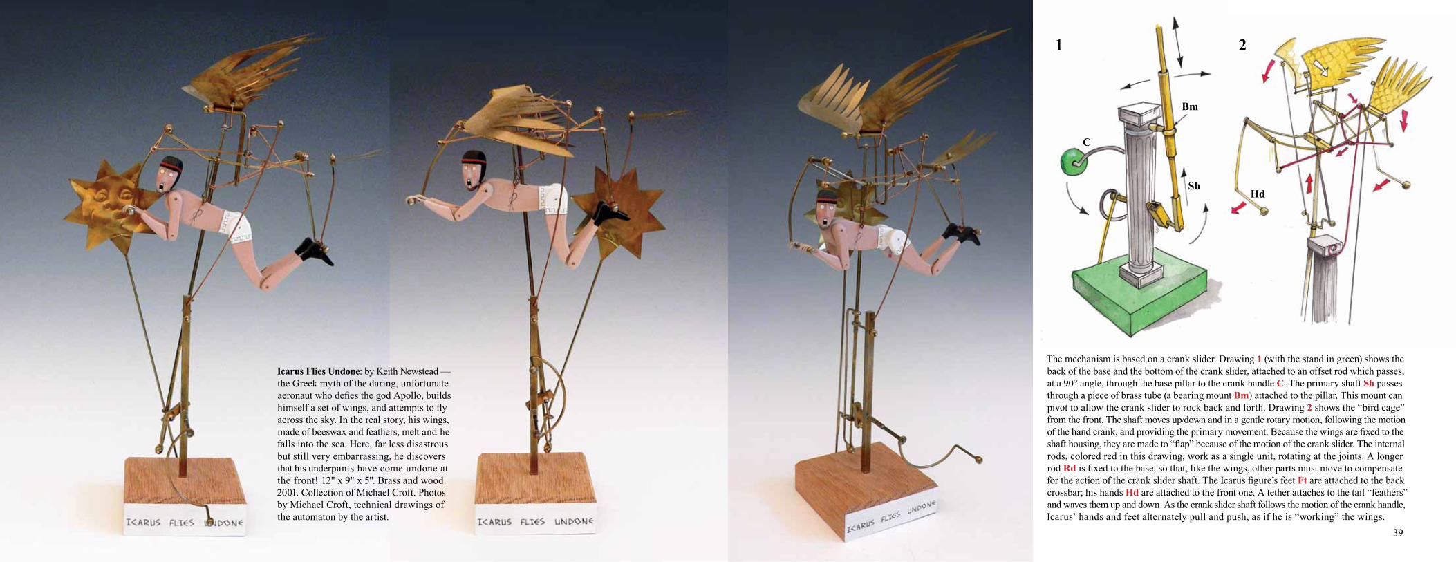
Icarus Flies Undone: by Keith Newstead —the Greek myth of the daring, unfortunate aeronaut who defies the god Apollo, builds himself a set of wings, and attempts to fly across the sky. In the real story, his wings, made of beeswax and feathers, melt and he falls into the sea. Here, far less disastrous but still very embarrassing, he discovers that his underpants have come undone at the front! 12" x 9" x 5". Brass and wood. 2001. Collection of Michael Croft. Photos by Michael Croft, technical drawings of the automaton by the artist.
The mechanism is based on a crank slider. Drawing 1 (with the stand in green) shows the back of the base and the bottom of the crank slider, attached to an offset rod which passes, at a 90° angle, through the base pillar to the crank handle C. The primary shaft Sh passes through a piece of brass tube (a bearing mount Bm) attached to the pillar. This mount can pivot to allow the crank slider to rock back and forth. Drawing 2 shows the “bird cage” from the front. The shaft moves up/down and in a gentle rotary motion, following the motion of the hand crank, and providing the primary movement. Because the wings are fixed to the shaft housing, they are made to “flap” because of the motion of the crank slider. The internal rods, colored red in this drawing, work as a single unit, rotating at the joints. A longer rod Rd is fixed to the base, so that, like the wings, other parts must move to compensate for the action of the crank slider shaft. The Icarus figure’s feet Ft are attached to the back crossbar; his hands Hd are attached to the front one. A tether attaches to the tail “feathers” and waves them up and down As the crank slider shaft follows the motion of the crank handle, Icarus’ hands and feet alternately pull and push, as if he is “working” the wings.
1 2
C
Sh
Bm
Hd
42 43
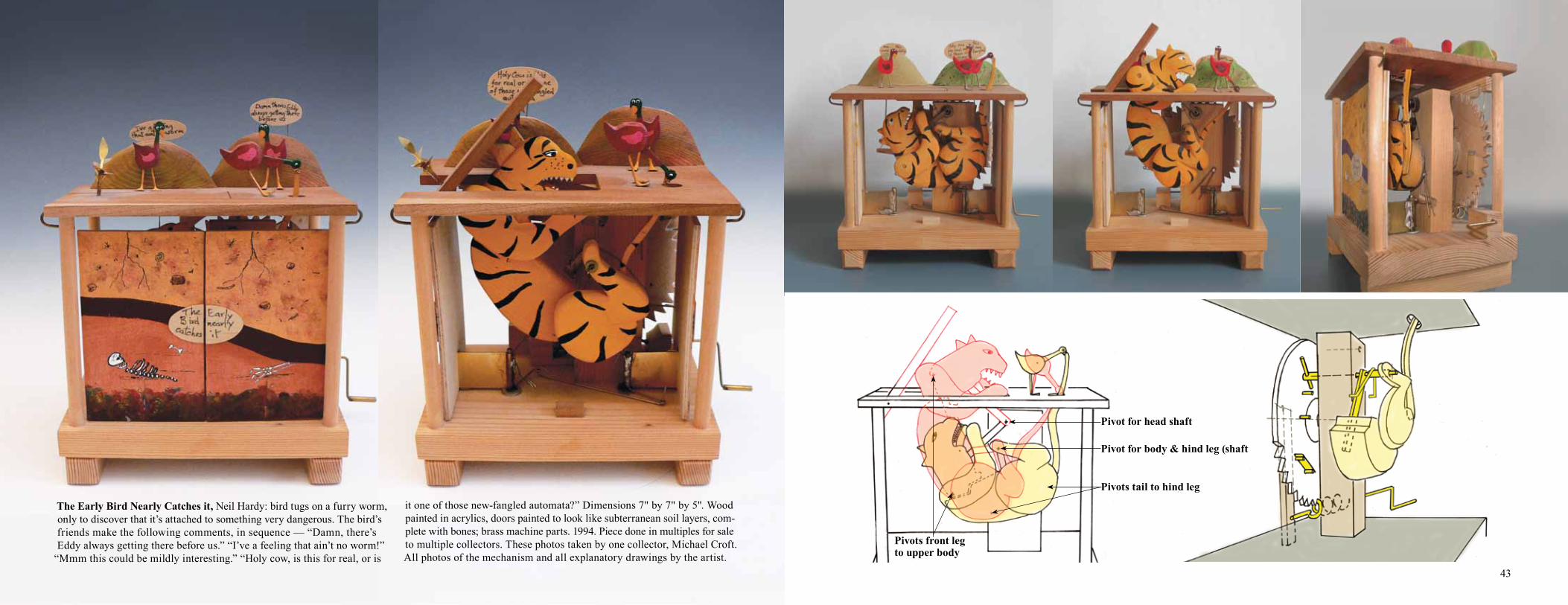
The Early Bird Nearly Catches it, Neil Hardy: bird tugs on a furry worm, only to discover that it’s attached to something very dangerous. The bird’s friends make the following comments, in sequence — “Damn, there’s Eddy always getting there before us.” “I’ve a feeling that ain’t no worm!”
“Mmm this could be mildly interesting.” “Holy cow, is this for real, or is
it one of those new-fangled automata?” Dimensions 7" by 7" by 5". Wood painted in acrylics, doors painted to look like subterranean soil layers, com-plete with bones; brass machine parts. 1994. Piece done in multiples for sale to multiple collectors. These photos taken by one collector, Michael Croft. All photos of the mechanism and all explanatory drawings by the artist.
MG
Cssp
Pn
Pn'
C
Br
Tbl Tbl
Cnp
WG
V
Esp
Co
Pivots front leg to upper body
Pivot for head shaft
Pivot for body & hind leg (shaft
Pivots tail to hind leg
44 45
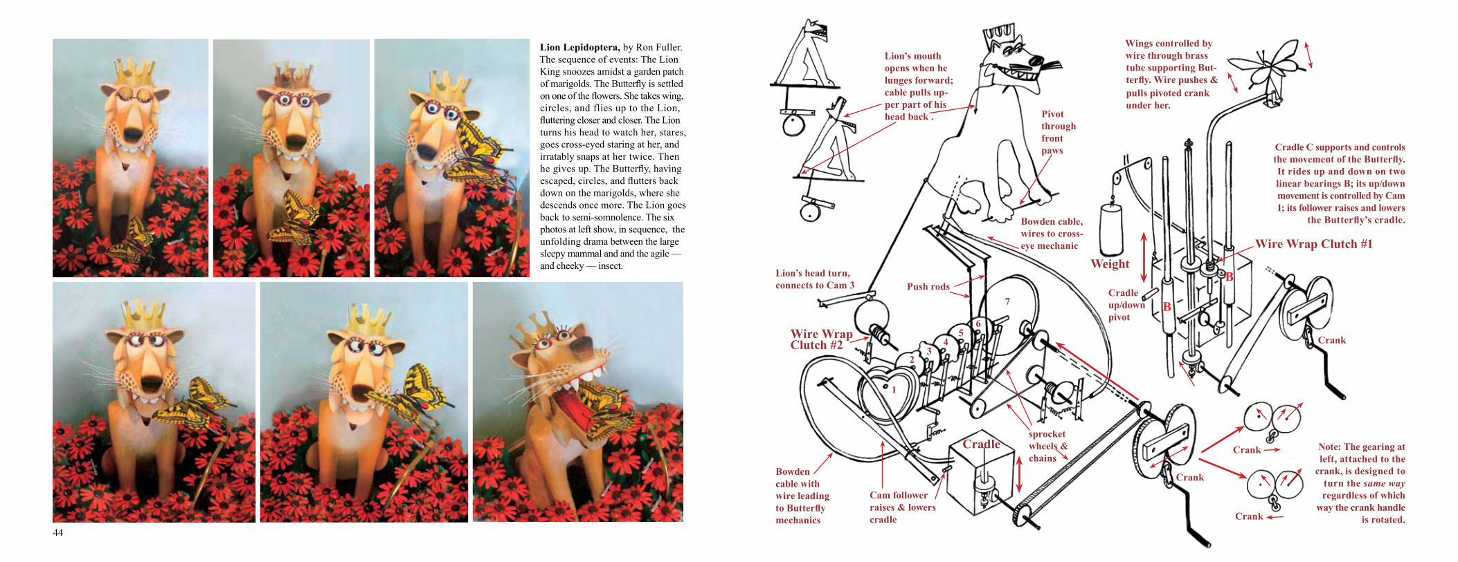
Lion Lepidoptera, by Ron Fuller. The sequence of events: The Lion King snoozes amidst a garden patch of marigolds. The Butterfly is settled on one of the flowers. She takes wing, circles, and flies up to the Lion, fluttering closer and closer. The Lion turns his head to watch her, stares, goes cross-eyed staring at her, and irratably snaps at her twice. Then he gives up. The Butterfly, having escaped, circles, and flutters back down on the marigolds, where she descends once more. The Lion goes back to semi-somnolence. The six photos at left show, in sequence, the unfolding drama between the large sleepy mammal and and the agile — and cheeky — insect.
Bowden cable, wires to cross-eye mechanic
Lion’s mouth opens when he lunges forward; cable pulls up-per part of his head back .
Wire Wrap Clutch #2
Bowden cable with wire leading to Butterfly mechanics
Cam follower raises & lowers cradle
1
23
45
6
7
sprocket wheels & chains
Note: The gearing at left, attached to the
crank, is designed to turn the same way regardless of which
way the crank handle is rotated.
Wings controlled by wire through brass tube supporting But-terfly. Wire pushes & pulls pivoted crank under her.
Cradle up/down pivot
Lion’s head turn, connects to Cam 3
Cradle C supports and controls the movement of the Butterfly. It rides up and down on two linear bearings B; its up/down movement is controlled by Cam 1; its follower raises and lowers
the Butterfly’s cradle.
Push rods
Pivot through front paws
Cradle
B
B
WeightWire Wrap Clutch #1
Crank
Crank
Crank
Crank
50 5150
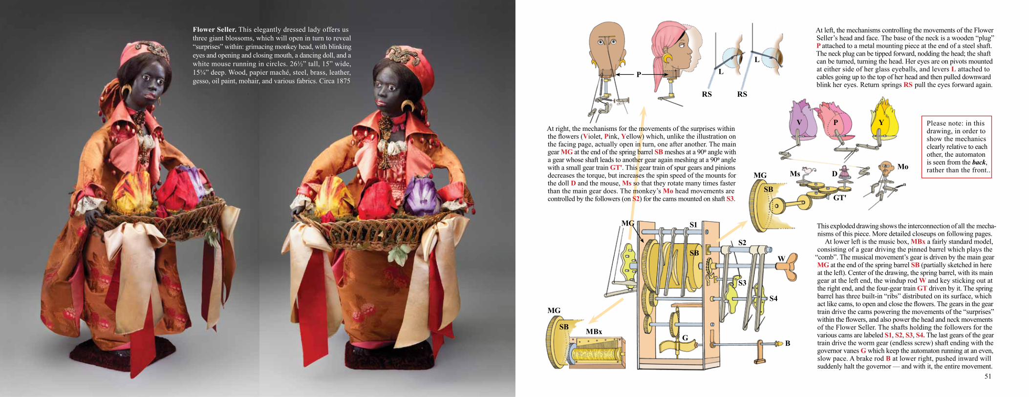
This exploded drawing shows the interconnection of all the mecha-nisms of this piece. More detailed closeups on following pages. At lower left is the music box, MBx a fairly standard model, consisting of a gear driving the pinned barrel which plays the
“comb”. The musical movement’s gear is driven by the main gear MG at the end of the spring barrel SB (partially sketched in here at the left). Center of the drawing, the spring barrel, with its main gear at the left end, the windup rod W and key sticking out at the right end, and the four-gear train GT driven by it. The spring barrel has three built-in “ribs” distributed on its surface, which act like cams, to open and close the flowers. The gears in the gear train drive the cams powering the movements of the “surprises” within the flowers, and also power the head and neck movements of the Flower Seller. The shafts holding the followers for the various cams are labeled S1, S2, S3, S4. The last gears of the gear train drive the worm gear (endless screw) shaft ending with the governor vanes G which keep the automaton running at an even, slow pace. A brake rod B at lower right, pushed inward will suddenly halt the governor — and with it, the entire movement.
MBx
W
S3
S4
S1
B
S2
G
Mo
GT'
YPV
MG
SB
Ms
SB
D
At left, the mechanisms controlling the movements of the Flower Seller’s head and face. The base of the neck is a wooden “plug” P attached to a metal mounting piece at the end of a steel shaft. The neck plug can be tipped forward, nodding the head; the shaft can be turned, turning the head. Her eyes are on pivots mounted at either side of her glass eyeballs, and levers L attached to cables going up to the top of her head and then pulled downward blink her eyes. Return springs RS pull the eyes forward again.
P
RS
LL
RS
Please note: in this drawing, in order to show the mechanics clearly relative to each other, the automaton is seen from the back, rather than the front..
SB
MG
At right, the mechanisms for the movements of the surprises within the flowers (Violet, Pink, Yellow) which, unlike the illustration on the facing page, actually open in turn, one after another. The main gear MG at the end of the spring barrel SB meshes at a 900 angle with a gear whose shaft leads to another gear again meshing at a 900 angle with a small gear train GT'. This gear train of spur gears and pinions decreases the torque, but increases the spin speed of the mounts for the doll D and the mouse, Ms so that they rotate many times faster than the main gear does. The monkey’s Mo head movements are controlled by the followers (on S2) for the cams mounted on shaft S3.
MG
Flower Seller. This elegantly dressed lady offers us three giant blossoms, which will open in turn to reveal “surprises” within: grimacing monkey head, with blinking eyes and opening and closing mouth, a dancing doll, and a white mouse running in circles. 26½” tall, 15” wide, 15¼” deep. Wood, papier maché, steel, brass, leather, gesso, oil paint, mohair, and various fabrics. Circa 1875
52 53
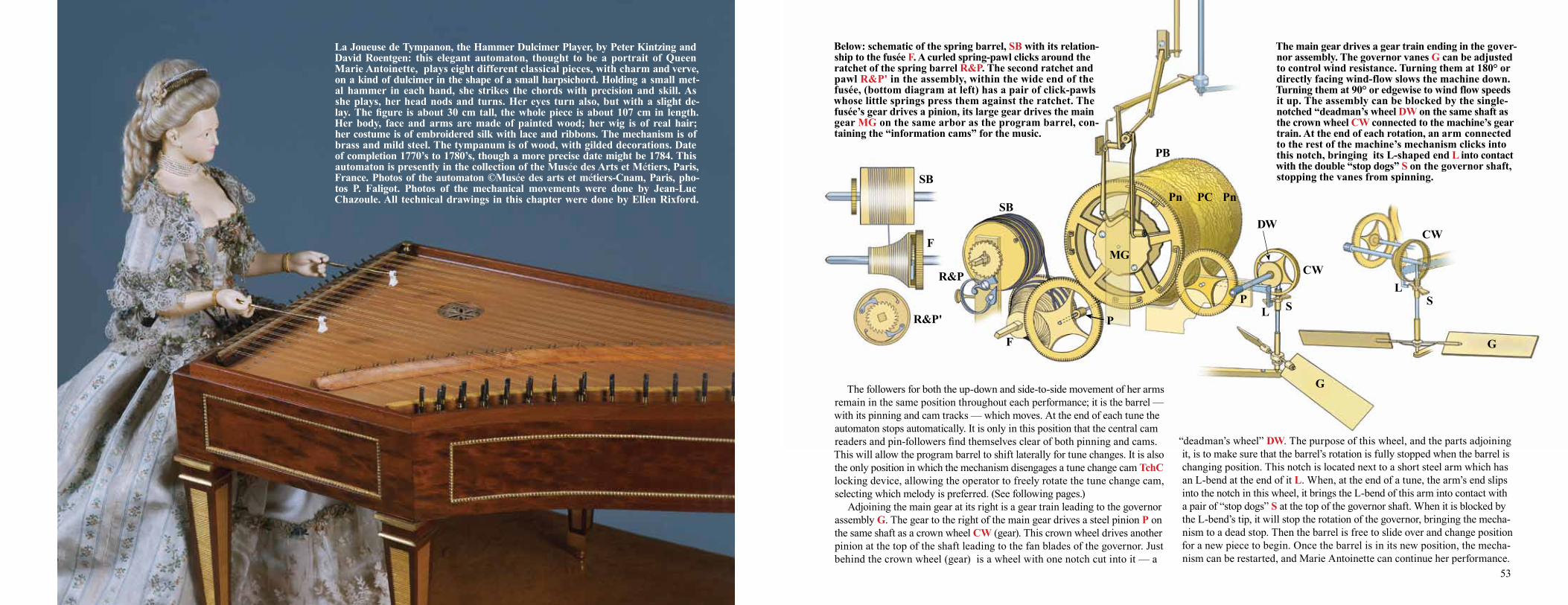
La Joueuse de Tympanon, the Hammer Dulcimer Player, by Peter Kintzing and David Roentgen: this elegant automaton, thought to be a portrait of Queen Marie Antoinette, plays eight different classical pieces, with charm and verve, on a kind of dulcimer in the shape of a small harpsichord. Holding a small met-al hammer in each hand, she strikes the chords with precision and skill. As she plays, her head nods and turns. Her eyes turn also, but with a slight de-lay. The figure is about 30 cm tall, the whole piece is about 107 cm in length. Her body, face and arms are made of painted wood; her wig is of real hair; her costume is of embroidered silk with lace and ribbons. The mechanism is of brass and mild steel. The tympanum is of wood, with gilded decorations. Date of completion 1770’s to 1780’s, though a more precise date might be 1784. This automaton is presently in the collection of the Musée des Arts et Métiers, Paris, France. Photos of the automaton ©Musée des arts et métiers-Cnam, Paris, pho-tos P. Faligot. Photos of the mechanical movements were done by Jean-Luc Chazoule. All technical drawings in this chapter were done by Ellen Rixford.
Below: schematic of the spring barrel, SB with its relation-ship to the fusée F. A curled spring-pawl clicks around the ratchet of the spring barrel R&P. The second ratchet and pawl R&P' in the assembly, within the wide end of the fusée, (bottom diagram at left) has a pair of click-pawls whose little springs press them against the ratchet. The fusée’s gear drives a pinion, its large gear drives the main gear MG on the same arbor as the program barrel, con-taining the “information cams” for the music.
The main gear drives a gear train ending in the gover-nor assembly. The governor vanes G can be adjusted to control wind resistance. Turning them at 180° or directly facing wind-flow slows the machine down. Turning them at 90° or edgewise to wind flow speeds it up. The assembly can be blocked by the single-notched “deadman’s wheel DW on the same shaft as the crown wheel CW connected to the machine’s gear train. At the end of each rotation, an arm connected to the rest of the machine’s mechanism clicks into this notch, bringing its L-shaped end L into contact with the double “stop dogs” S on the governor shaft, stopping the vanes from spinning.
SB
F
R&P
SB
F
R&P'
MG
DWCW
G
LSSL
PC
CW
P
PnPn
PB
P
The followers for both the up-down and side-to-side movement of her arms remain in the same position throughout each performance; it is the barrel — with its pinning and cam tracks — which moves. At the end of each tune the automaton stops automatically. It is only in this position that the central cam readers and pin-followers find themselves clear of both pinning and cams. This will allow the program barrel to shift laterally for tune changes. It is also the only position in which the mechanism disengages a tune change cam TchC locking device, allowing the operator to freely rotate the tune change cam, selecting which melody is preferred. (See following pages.) Adjoining the main gear at its right is a gear train leading to the governor assembly G. The gear to the right of the main gear drives a steel pinion P on the same shaft as a crown wheel CW (gear). This crown wheel drives another pinion at the top of the shaft leading to the fan blades of the governor. Just behind the crown wheel (gear) is a wheel with one notch cut into it — a
“deadman’s wheel” DW. The purpose of this wheel, and the parts adjoining it, is to make sure that the barrel’s rotation is fully stopped when the barrel is changing position. This notch is located next to a short steel arm which has an L-bend at the end of it L. When, at the end of a tune, the arm’s end slips into the notch in this wheel, it brings the L-bend of this arm into contact with a pair of “stop dogs” S at the top of the governor shaft. When it is blocked by the L-bend’s tip, it will stop the rotation of the governor, bringing the mecha-nism to a dead stop. Then the barrel is free to slide over and change position for a new piece to begin. Once the barrel is in its new position, the mecha-nism can be restarted, and Marie Antoinette can continue her performance.
G
54 55
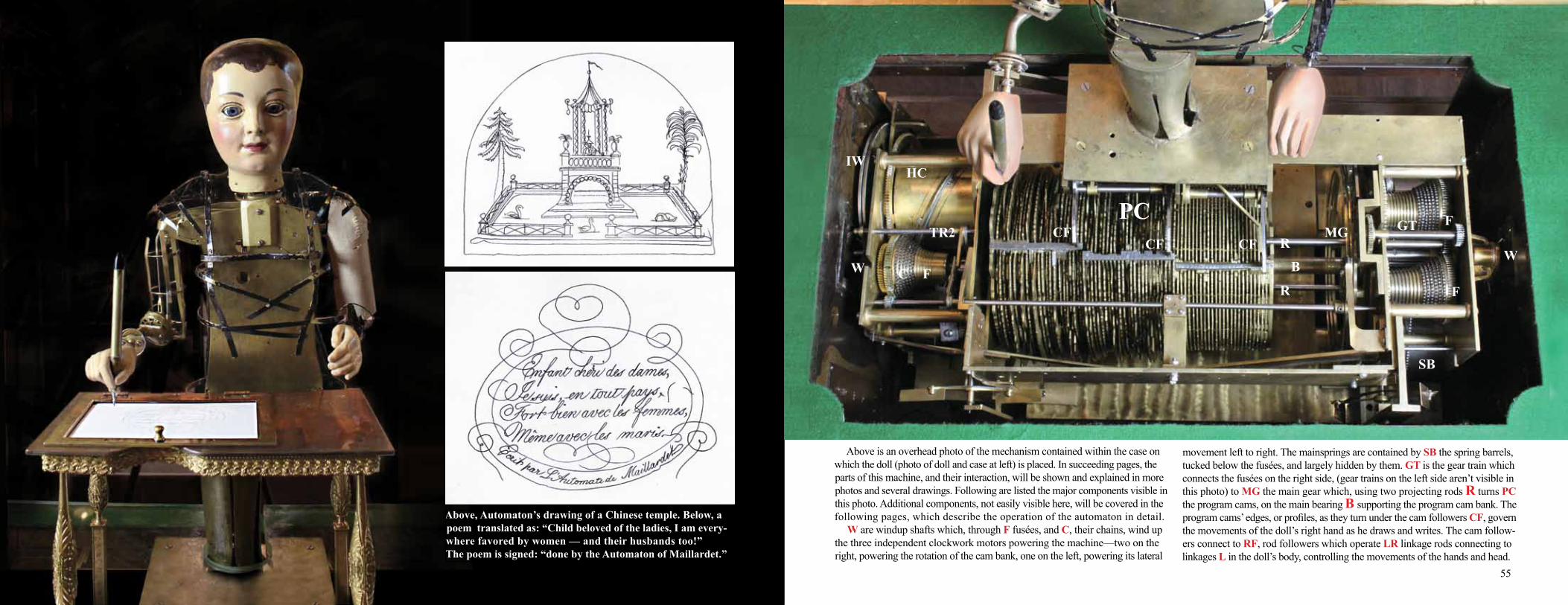
Above, Automaton’s drawing of a Chinese temple. Below, a poem translated as: “Child beloved of the ladies, I am every-where favored by women — and their husbands too!” The poem is signed: “done by the Automaton of Maillardet.”
Above is an overhead photo of the mechanism contained within the case on which the doll (photo of doll and case at left) is placed. In succeeding pages, the parts of this machine, and their interaction, will be shown and explained in more photos and several drawings. Following are listed the major components visible in this photo. Additional components, not easily visible here, will be covered in the following pages, which describe the operation of the automaton in detail. W are windup shafts which, through F fusées, and C, their chains, wind up the three independent clockwork motors powering the machine—two on the right, powering the rotation of the cam bank, one on the left, powering its lateral
movement left to right. The mainsprings are contained by SB the spring barrels, tucked below the fusées, and largely hidden by them. GT is the gear train which connects the fusées on the right side, (gear trains on the left side aren’t visible in this photo) to MG the main gear which, using two projecting rods R turns PC the program cams, on the main bearing B supporting the program cam bank. The program cams’ edges, or profiles, as they turn under the cam followers CF, govern the movements of the doll’s right hand as he draws and writes. The cam follow-ers connect to RF, rod followers which operate LR linkage rods connecting to linkages L in the doll’s body, controlling the movements of the hands and head.
SB
CTR1
FG FG
PC F
F
WW
GTMGCFCF CF
HCIW
TR2R
R
BFC
SB