Sample Lesson - CamInstructor
32
TRAINING GUIDE MILL-LESSON-9 SURFACE POCKET AND SURFACE HIGH SPEED WATERLINE Sample not for Distribution
Transcript of Sample Lesson - CamInstructor

TRAINING
GUIDE
MILL-LESSON-9
SURFACE POCKET AND SURFACE
HIGH SPEED WATERLINE
Sample
not for
Distrib
ution

Mastercam Training Guide
Mill-Lesson-9-1
Objectives You will create the geometry for Mill-Lesson-9, and then generate the toolpaths to machine the part on a CNC vertical milling machine. This Lesson covers the following topics: Create a 3-dimensional drawing by: Creating lines. Creating arcs. Trimming geometry using Divide / Delete. Creating a revolved surface. Establish Stock Setup settings: Stock size using Bounding Box. Material for the part. Feed calculation. Generate a 3-dimensional milling toolpath
consisting of: Surface Pocket. Surface High Speed Waterline. Inspect the toolpath using Mastercam’s Verify and Backplot by: Launching the Verify function to machine the part on the screen. Generating the NC- code.
Sample
not for
Distrib
ution

Mill-Lesson-9
Mill-Lesson-9-2
MILL-LESSON-9 DRAWING
Sample
not for
Distrib
ution

Mastercam Training Guide
Mill-Lesson-9-3
TOOL LIST 0.500 diameter bull end mill with a 0.125 corner radius to rough machine the pocket. 0.500 diameter ball end mill to finish machine the pocket.
MILL-LESSON-9 - THE PROCESS
Geometry Creation TASK 1: Setting environment TASK 2: Create geometry TASK 3: Trim the geometry TASK 4: Create the revolved surface TASK 5: Create boundary curves TASK 6: Save the drawing
Toolpath Creation TASK 7: Define the rough stock using stock setup TASK 8: Rough the pocket using surface pocket TASK 9: Finish the pocket using surface high speed waterline TASK 10: Verify the toolpath TASK 11: Save the updated Mastercam file TASK 12: Post and create the CNC code file
Sample
not for
Distrib
ution

Mill-Lesson-9
Mill-Lesson-9-4
TASK 1: SETTING THE ENVIRONMENT Before starting the geometry creation you should set up the grid, toolbars and machine type as outlined in the Setting the environment section at the beginning of this text: 1. Set up the Grid. This will help identify the location of the origin. 2. Customize the toolbars to machine a 3D part. 3. Set the machine type to a Haas Vertical Spindle CNC machine.
TASK 2: CREATE GEOMETRY - X0 Y0 LOWER LEFT CORNER In this task you will create the geometry that will be used to create the revolved surface. First
you will create the circles, C1 through C4 and then create the lines 1 through 7. The arc C5 will be created using Fillet.
Create Circle #1 1. Select Create>Arc>Circle Center point… 2. The Circle Center Point ribbon bar appears and you are prompted to Enter the center
point.
3. Before moving on, click in the space for radius and enter a value of 0.25. Next click on the
icon for radius on the ribbon bar as shown below. This locks in the radius for the circles. To unlock click on the icon for diameter.
4. To satisfy this first prompt click on the FastPoint Icon on the Auto Cursor ribbon bar . 5. In the space input the X (0.25) and Y (0.5) values for the center of the circle and hit enter.
Note that you can use a variety of formats to enter coordinates here. This is very helpful when cutting and pasting coordinate values from another document. You do not need to input the Z value for this example.
6. On the ribbon bar click on Apply to fix the entity. Create Circle #2 7. To satisfy the prompt Enter the center point click on the FastPoint Icon on the Auto Cursor
ribbon bar. 8. In the space input the X (0.625) and Y (0.5) values for the center of the circle and then hit
the enter key.
9. On the ribbon bar click on Apply to fix the entity.
Sample
not for
Distrib
ution

Mastercam Training Guide
Mill-Lesson-9-5
Create Circle #3 10. To satisfy the prompt Enter the center point click on the FastPoint Icon on the Auto Cursor
ribbon bar. 11. In the space input the X (3.750-1.858) and Y (0.5+0.25) values for the center of the circle
and then hit the enter key.
12. On the ribbon bar click on Apply to fix the entity. Create Circle #4 13. To satisfy the prompt Enter the center point click on the FastPoint Icon on the Auto Cursor
ribbon bar. 14. In the space input the X (3.750-0.25) and Y (0.625) values for the center of the circle and
then hit the enter key.
15. Click on the OK icon to complete this feature.
16. Now select the Fit to screen icon . Create Line #1 17. Select from the pull down menu: Create>Line>Line Endpoint… 18. On the graphics screen you are prompted: Specify the first endpoint and the Line ribbon
bar appears. Note that the Tangent function is activated.
19. To satisfy the prompt Specify the first endpoint move the cursor over to the center of the
grid and as you get close to the Origin (X0Y0) a visual cue appears. This is the cue that will allow you to snap to the origin, with this visual cue highlighted pick the origin.
20. To satisfy the prompt Specify the second endpoint move the cursor over the area of the circle shown below. Ensure there is no visual snap cue being displayed and click on this point. As Tangent is activated on the line ribbon bar the line will snap to the closest tangency point on the circle as shown below right:
21. On the ribbon bar click on Apply to fix the entity.
Sample
not for
Distrib
ution

Mill-Lesson-9
Mill-Lesson-9-6
Create Line #2 22. To satisfy the prompt Specify the first endpoint move the cursor over the area of the circle
shown below. Ensure there is no visual cue being displayed and click on this point. As Tangent is activated on the line ribbon bar the line will snap to the closes tangency point on the circle.
23. To satisfy the prompt Specify the second endpoint move the cursor over the area of the
circle shown below. Ensure there is no visual cue being displayed and click on this point. As Tangent is activated on the line ribbon bar the line will snap to the closest tangency point on the circle as shown below right.
24. On the ribbon bar click on Apply to fix the entity. Create Line #3 25. To satisfy the prompt Specify the first endpoint move the cursor over the area of the circle
shown below. Ensure there is no visual cue being displayed and click on this point.
Sample
not for
Distrib
ution

Mastercam Training Guide
Mill-Lesson-9-7
26. To satisfy the prompt Specify the second endpoint move the cursor over the area of the circle shown below. Ensure there is no visual cue being displayed and click on this point. As Tangent is activated on the line ribbon bar the line will snap to the closest tangency point on the circle.
27. On the ribbon bar click on Apply to fix the entity. Create Line #4 28. Click in the space for Length and enter a value of 0.5 and then hit the tab key. In the space
for Angle and enter a value of -40.0 and hit enter.
29. To satisfy the prompt Specify the first endpoint move the cursor over the area of the circle
shown below. Ensure there is no visual cue being displayed and click on this point.
30. To satisfy the prompt Select a line pick the lower line as shown below:
31. On the ribbon bar click on Apply to fix the entity.
Sample
not for
Distrib
ution

Mill-Lesson-9
Mill-Lesson-9-8
Create Line #5 32. To satisfy the prompt Specify the first endpoint use the AutoCursor ribbon bar Override
drop down list. Open the drop down and select Quadrant. Move the cursor over the area of the circle shown below right and click on the circle:
33. To satisfy the prompt Specify the second endpoint move the cursor over to the left of the
circle shown below. Ensure the visual cue for Horizontal/Vertical is displayed and click on this point.
34. On the ribbon bar click on Apply to fix the entity. Create Line #6 35. Click on the Multi-line button to activate it.
36. To satisfy the prompt Specify the first endpoint move the cursor over to the center of the
grid a visual cue appears. With this visual cue highlighted pick the origin. 37. Click in the space for Length and enter a value of 3.75 and then hit the tab key. In the
space for Angle enter a value of 0 and hit enter.
Create Line #7 38. To satisfy the prompt Specify the second endpoint move the cursor over to the right of the
circle shown below. When the visual cue for Endpoint is displayed click on this point.
39. Click on the OK icon to complete this feature.
Sample
not for
Distrib
ution

Mastercam Training Guide
Mill-Lesson-9-9
Create Circle #5 40. Select Create>Fillet>Fillet Entities… 41. On the Fillet ribbon bar enter .25 for the radius. Ensure the Style of radius is set to
Normal and the trim button is depressed to turn the trim on.
42. When prompted to Fillet: Select an entity, select the two lines shown below:
43. Click on the OK icon to complete this feature.
TASK 3: TRIM GEOMETRY In this task you will trim the geometry using Divide / Delete. There are many different ways
to accomplish this trimming operation, this is just one method. If you make a mistake using Divide / Delete use the Undo button to start over.
Trim the circles 1. Select Edit>Trim/Break>Trim/Break/Extend 2. The Trim / Extend / Break ribbon bar appears and you are prompted to Select the entity to
trim/extend.
3. Click on the Divide / Delete icon to activate it as shown above. Ensure the icon is pressed down to signal that it is activated.
4. The prompt changes to Select the curve to divide / delete. Move the cursor over the various circles and select in order and position as shown below. The arc is trimmed back to the two closest intersections/end points as shown below. Placing the cursor over the entity to divide / delete shows a preview as shown below left.
Note: On some of the circles you will need to select them more than once to completely trim them.
Sample
not for
Distrib
ution

Mill-Lesson-9
Mill-Lesson-9-10
5. Click on the OK icon to complete this feature. The completed geometry is shown below:
TASK 4: CREATE THE REVOLVED SURFACE In this task you will create a revolved surface using the geometry you have just created and revolve the geometry 180 degrees about the X axis.
Revolved surfaces are circular in one direction. You will be prompted to chain an entity that the revolved surface will use as a profile. You may choose multiple entities to create many revolved surfaces at a time. You are then prompted to choose a line to use as the axis of rotation and the revolved surface is created. If you have chosen multiple entities, a surface for each entity will be created, each having a different profile and position and all using the same axis of rotation. Click Apply or Enter when done.
Create Revolved Surface 1. Select from the pull down menu: Create>Surface>Revolved… 2. On the graphics screen you are prompted: Select profile curve(s) 1. In the Chaining dialog
window select Partial Chain as shown below: 3. Select line 1 and ensure the arrow is pointing upwards. If not click on the reverse icon. 4. Then select line 2 as shown below:
Sample
not for
Distrib
ution
Mastercam Training Guide
Mill-Lesson-9-11
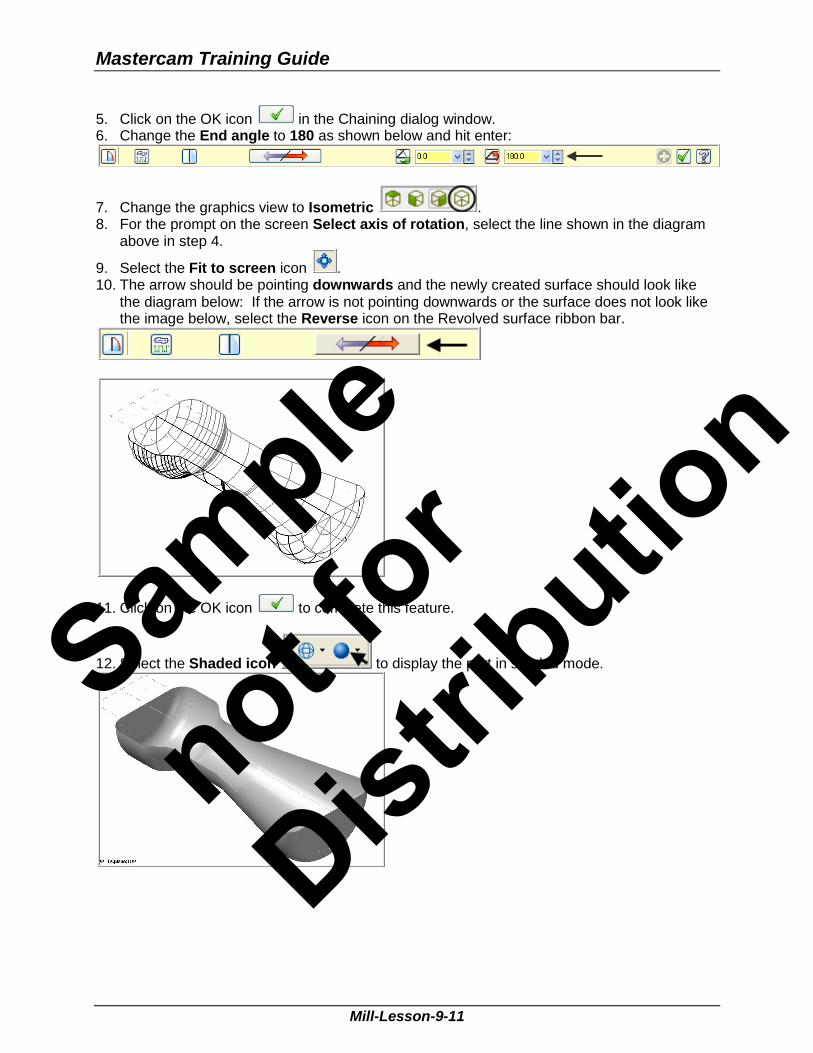
5. Click on the OK icon in the Chaining dialog window. 6. Change the End angle to 180 as shown below and hit enter:
7. Change the graphics view to Isometric . 8. For the prompt on the screen Select axis of rotation, select the line shown in the diagram
above in step 4.
9. Select the Fit to screen icon . 10. The arrow should be pointing downwards and the newly created surface should look like
the diagram below: If the arrow is not pointing downwards or the surface does not look like the image below, select the Reverse icon on the Revolved surface ribbon bar.
11. Click on the OK icon to complete this feature.
12. Select the Shaded icon to display the part in shaded mode.
Sample
not for
Distrib
ution
Mill-Lesson-9
Mill-Lesson-9-12
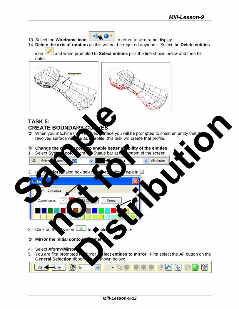
13. Select the Wireframe icon to return to wireframe display. 14. Delete the axis of rotation as this will not be required anymore. Select the Delete entities
icon and when prompted to Select entities pick the line shown below and then hit enter.
TASK 5: CREATE BOUNDARY CURVES When you machine the Revolved surface you will be prompted to chain an entity that the
revolved surface will use as a profile, this task will create that profile. Change the current color to enable better visibility of the entities 1. Select System color from the Status bar at the bottom of the screen.
2. In the Colors dialog box select the red color or type in 12.
3. Click on the OK icon to complete this feature. Mirror the initial contour geometry 4. Select Xform>Mirror… 5. You are first prompted to Mirror: select entities to mirror. First select the All button on the
General Selection ribbon bar as shown below:
Sample
not for
Distrib
ution
Mastercam Training Guide
Mill-Lesson-9-13
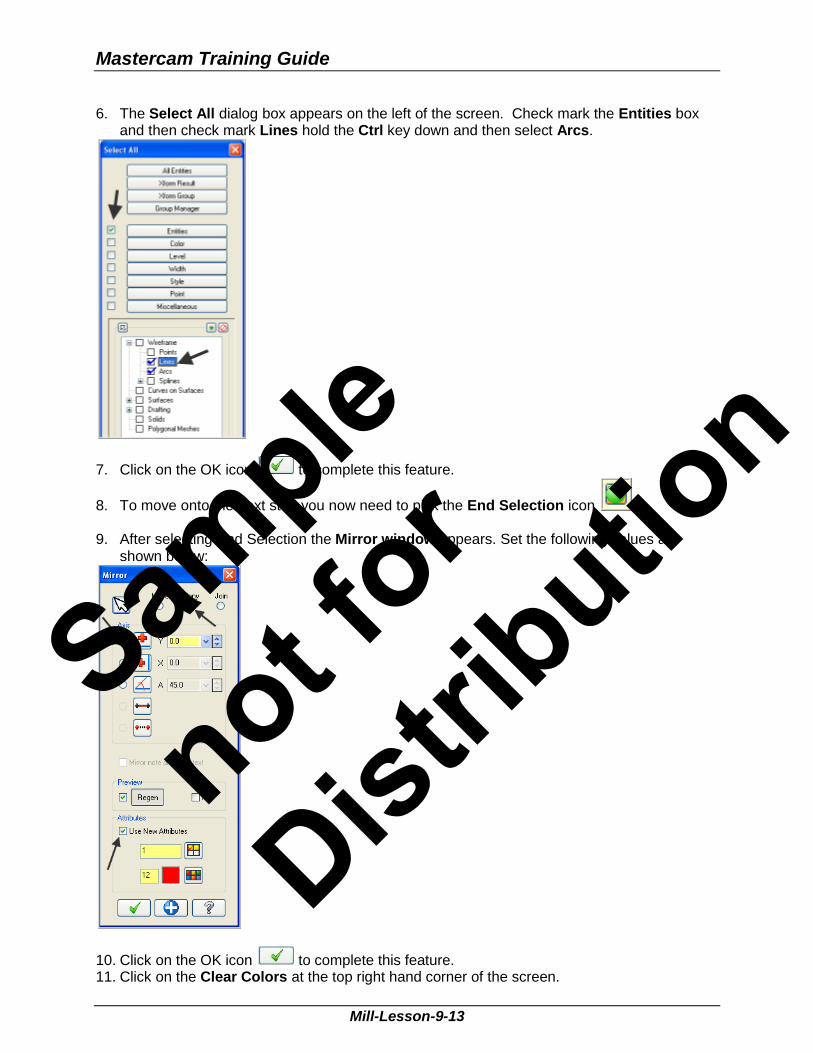
6. The Select All dialog box appears on the left of the screen. Check mark the Entities box and then check mark Lines hold the Ctrl key down and then select Arcs.
7. Click on the OK icon to complete this feature.
8. To move onto the next step you now need to pick the End Selection icon . 9. After selecting End Selection the Mirror window appears. Set the following values as
shown below:
10. Click on the OK icon to complete this feature. 11. Click on the Clear Colors at the top right hand corner of the screen.
Sample
not for
Distrib
ution

Mill-Lesson-9
Mill-Lesson-9-14
TASK 6: SAVE THE DRAWING 1. Select File. 2. Select Save as. 3. In the File name box, type Mill-Lesson-9. 4. Save to an appropriate location. 5. Select the Save button to save the file and complete this function.
Toolpath Creation
TASK 7: DEFINE THE ROUGH STOCK USING STOCK SETUP
1. Fit to screen . 2. Select the plus in front of Properties to expand the Toolpaths Group Properties. Alt-O will
Show/hide Operations Manager pane.
3. Select Stock setup in the Toolpaths Manager window.
Sample
not for
Distrib
ution

Mastercam Training Guide
Mill-Lesson-9-15
4. Change the parameters to match the Stock Setup screenshot below: Z zero is at the top of the part.
5. Select the Tool Settings tab and change the parameters to match the Tool Settings
screenshot below. To change the Material type follow the instructions below:
6. To change the Material type to
Aluminium 6061 pick the Select button at the bottom of the Tool Settings page.
7. At the Material List dialog box open
the Source drop down list and select Mill – library.
8. From the Default Materials list select
ALUMINIUM inch -6061 and then
select .
9. Select the OK button again to complete this Stock Setup function.
Sample
not for
Distrib
ution

Mill-Lesson-9
Mill-Lesson-9-16
Your part should look similar to the screen shot below. With X0 Y0 at the middle left side and Z zero at the top of the part.
Surface roughing toolpaths typically use larger tools, multiple stepovers, and multiple step downs to quickly remove larger volumes of stock and leave an even amount of stock for finishing. The roughing toolpaths you choose for your part depend on the shape of the part, shape of the stock, and machining situation. Mastercam provides several roughing strategies.
TASK 8: ROUGH THE POCKET USING SURFACE POCKET In this task you will use a 0.5 diameter bull end mill with a 0.125 corner radius to rough out
the pocket. 1. From the menu bar select Toolpaths>Surface Rough>Pocket… 2. When prompted to Enter new NC name ensure Mill-LESSON-9 is entered and then select
the OK button . 3. You are first prompted to Select Drive surfaces, select the All button on the General
Selection ribbon bar as shown below:
4. The Select All dialog box appears on the screen.
5. Click on the OK icon to complete and exit this feature.
6. To move onto the next step you now need to pick the End Selection icon . 7. Select the Containment button from the Toolpath/surface selection dialog box.
Use this dialog box to select all the geometry needed for a surface toolpath. Each surface toolpath requires drive geometry selected from the graphics window or from a CAD file.
Sample
not for
Distrib
ution

Mastercam Training Guide
Mill-Lesson-9-17
8. On the screen you will now see the Chaining dialog box with Chain set and in the graphics screen a prompt to Chain 2D tool containment boundary #1. Ensure the C-plane radio button is activated. Now select the line as shown below:
9. After the boundary has been successfully chained select the OK button .
10. Select the OK button to exit the Toolpath/surface selection dialog box. 11. In the lower left corner of the Toolpath parameters page select the Select library tool…
button. Disable Filter active. 12. Use the slider bar on the right of this dialog box to scroll down and locate a 0.5 diameter
bull end mill with a 0.125 corner radius. Select the end mill by picking anywhere along its row.
13. Select the OK button to complete the selection of this tool. Sample
not for
Distrib
ution

Mill-Lesson-9
Mill-Lesson-9-18
14. Make changes to the Toolpath parameters page as shown below. Set coolant on.
15. Select the Surface parameters page and make changes to this page as shown below:
Stock to leave on drive is set to 0.020.
Tool Containment Specify the behaviour of the containment boundary. Compensate to Inside Keep the tool inside this boundary. Compensate to Center Keep the tool centerline inside the boundary (allow up to half of the tool to exit the boundary). Compensate to Outside Allow the entire tool to exit the boundary but keep the tool edge in contact with the boundary.
Sample
not for
Distrib
ution

Mastercam Training Guide
Mill-Lesson-9-19
16. Select the Rough Parameters page and make changes to this page as shown below:
Tolerance selection will vary based on the toolpath type (roughing, semi-finish, or finishing), tolerances of final part, surface finish required, etc. For the purposes of this tutorial, we will use .001 for both roughing and finishing to find a balance between accuracy and calculation time. Typical tolerance ranges are from .0001 to .001.
17. Select the Cut depths button make the necessary changes.
Cut depths specify the placement of Z-axis cuts for all rough surface toolpaths and for finish contour toolpaths. Incremental cut depths Incremental cut depths are measured from the top and bottom of the part for most rough surface toolpaths and for finish contour toolpaths. Keep top cut at max stepdown Available only for rough pocket toolpaths. Forces the tool to make the first cutting pass at the max cut depth instead of the top of the part.
18. Select the OK button to complete this feature.
Sample
not for
Distrib
ution

Mill-Lesson-9
Mill-Lesson-9-20
19. Select the Entry/Helix button make the necessary changes.
Helix/Ramp Use this to add a ramp entry move to the pocket roughing operation. You can add either a helix or a ramp entry, but not both. To switch between ramp or helical entry, just select the other tab and enter the desired entry dimensions. The helix/ramp options are off by default. If no helix/ramp options are set, Mastercam plunges the tool to the pocket depth at the start of the toolpath.
20. Select the OK button to complete this feature. 21. Select the Pocket parameters page and make changes to this page as shown below.
Cutting method: High Speed.
22. Select the OK button to exit Pocket parameters. 23. It may take a while for Mastercam to create the toolpath.
Sample
not for
Distrib
ution

Mastercam Training Guide
Mill-Lesson-9-21
24. The screen should look like the image below:
TASK 9: FINISH THE POCKET USING SURFACE HIGH SPEED WATERLINE In this task you will use a 0.5 diameter Ball end mill to finish the pocket. The rough parallel toolpath removes stock quickly using multiple constant Z depth. Surface
High Speed Waterline also works at constant Z depth and steps down with cuts directly on the surface.
1. From the menu bar select Toolpaths>Surface High Speed>Waterline… 2. You are first prompted to Select Drive surfaces, select the All button on the General
Selection ribbon bar as shown below:
3. The Select All dialog box appears on the screen.
4. Click on the OK icon to complete and exit this feature.
5. To move onto the next step you now need to pick the End Selection icon . 6. Select the Containment button from the Toolpath/surface selection dialog box.
Sample
not for
Distrib
ution

Mill-Lesson-9
Mill-Lesson-9-22
7. On the screen you will now see the Chaining dialog box with Chain set and in the graphics screen a prompt to Chain 2D tool containment boundary #1. Ensure the C-plane radio button is activated. Toolpath display has been turned off for clarity ALT + T. Now select the line as shown below:
8. After the boundary has been successfully chained select the OK button .
9. Select the OK button to exit the Toolpath/surface selection dialog box. 10. For the Toolpath Type, select the Finishing radio button, and the Waterline toolpath.
Sample
not for
Distrib
ution

Mastercam Training Guide
Mill-Lesson-9-23
11. Select the Tool selection page, then Select library tool… button. 12. Select the Filter button on the right side of the Tool selection dialog box. 13. Select the None button in the Tool Types section. 14. Click on the Endmill2 Sphere type icon as shown in the picture (1) below: 15. Select the drop down arrow in the Tool diameter (2) field and set it to Equal. 16. Input the tool diameter (3) as 0.5.
17. Select the OK button to exit. 18. Select the 0.5 ball end mill.
19. Select the OK button to complete the selection of this tool. Sample
not for
Distrib
ution
Mill-Lesson-9
Mill-Lesson-9-24
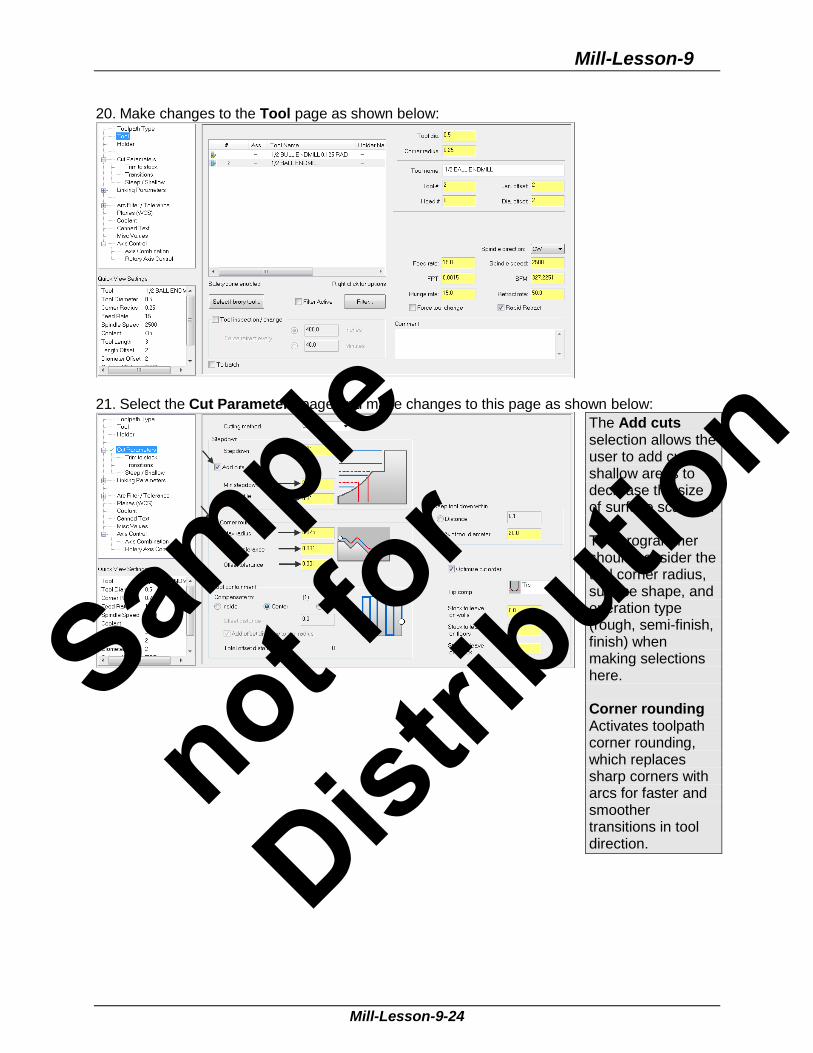
20. Make changes to the Tool page as shown below:
21. Select the Cut Parameters page and make changes to this page as shown below:
The Add cuts selection allows the user to add cuts in shallow areas to decrease the size of surface scallops. The programmer should consider the tool corner radius, surface shape, and operation type (rough, semi-finish, finish) when making selections here. Corner rounding Activates toolpath corner rounding, which replaces sharp corners with arcs for faster and smoother transitions in tool direction.
Sample
not for
Distrib
ution
Mastercam Training Guide
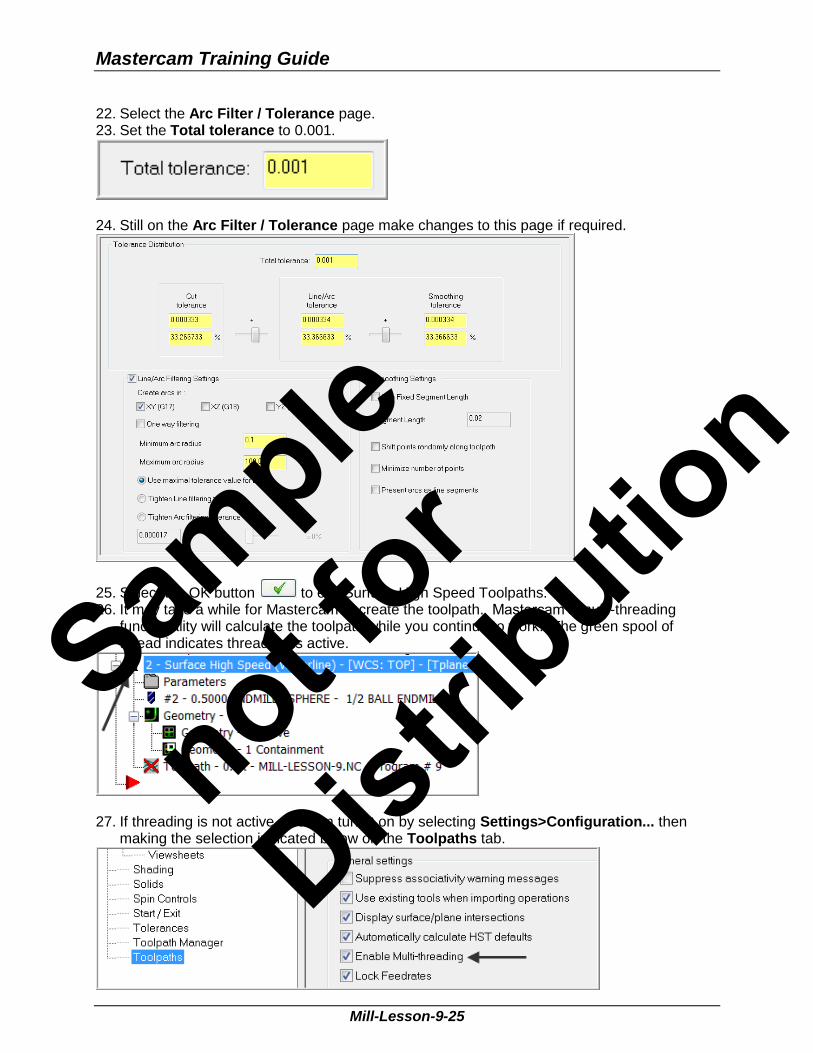
Mill-Lesson-9-25
22. Select the Arc Filter / Tolerance page. 23. Set the Total tolerance to 0.001.
24. Still on the Arc Filter / Tolerance page make changes to this page if required.
25. Select the OK button to exit Surface High Speed Toolpaths. 26. It may take a while for Mastercam to create the toolpath. Mastercam’s multi-threading
functionality will calculate the toolpath while you continue to work. The green spool of thread indicates threading is active.
27. If threading is not active, you can turn it on by selecting Settings>Configuration... then
making the selection indicated below on the Toolpaths tab.
Sample
not for
Distrib
ution

Mill-Lesson-9
Mill-Lesson-9-26
The screen should look like the image below with the toolpaths displayed:
Sample
not for
Distrib
ution
Mastercam Training Guide
Mill-Lesson-9-27
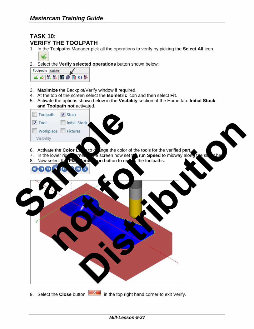
TASK 10: VERIFY THE TOOLPATH 1. In the Toolpaths Manager pick all the operations to verify by picking the Select All icon
2. Select the Verify selected operations button shown below:
3. Maximize the Backplot/Verify window if required. 4. At the top of the screen select the Isometric icon and then select Fit. 5. Activate the options shown below in the Visibility section of the Home tab. Initial Stock
and Toolpath not activated.
6. Activate the Color Loop to change the color of the tools for the verified part. 7. In the lower right corner of the screen now set the run Speed to midway along the slider bar. 8. Now select the Play Simulation button to review the toolpaths.
9. Select the Close button in the top right hand corner to exit Verify.
Sample
not for
Distrib
ution

Mill-Lesson-9
Mill-Lesson-9-28
TASK 11: SAVE THE UPDATED MASTERCAM FILE 1. Select the save icon from the toolbar.
TASK 12: POST AND CREATE THE CNC CODE FILE
1. Ensure all the operations are selected by picking the Select All icon from the Toolpaths Manager.
2. Select the Post selected operations button from the Toolpaths Manager. Please Note: If you cannot see G1 click on the right pane of the Toolpath Manager window and expand the window to the right.
3. In the Post processing window, make the necessary changes as shown below:
4. Select the OK button to continue. 5. Enter the same name as your Mastercam part file name in the NC File name field Mill-
Lesson-9. 6. Select the Save button. 10. The CNC code file opens up in the default editor:
11. Select the in the top right corner to exit the CNC editor. This completes Mill-Lesson-9.
Sample
not for
Distrib
ution
Mastercam Training Guide
Mill-Lesson-9-29
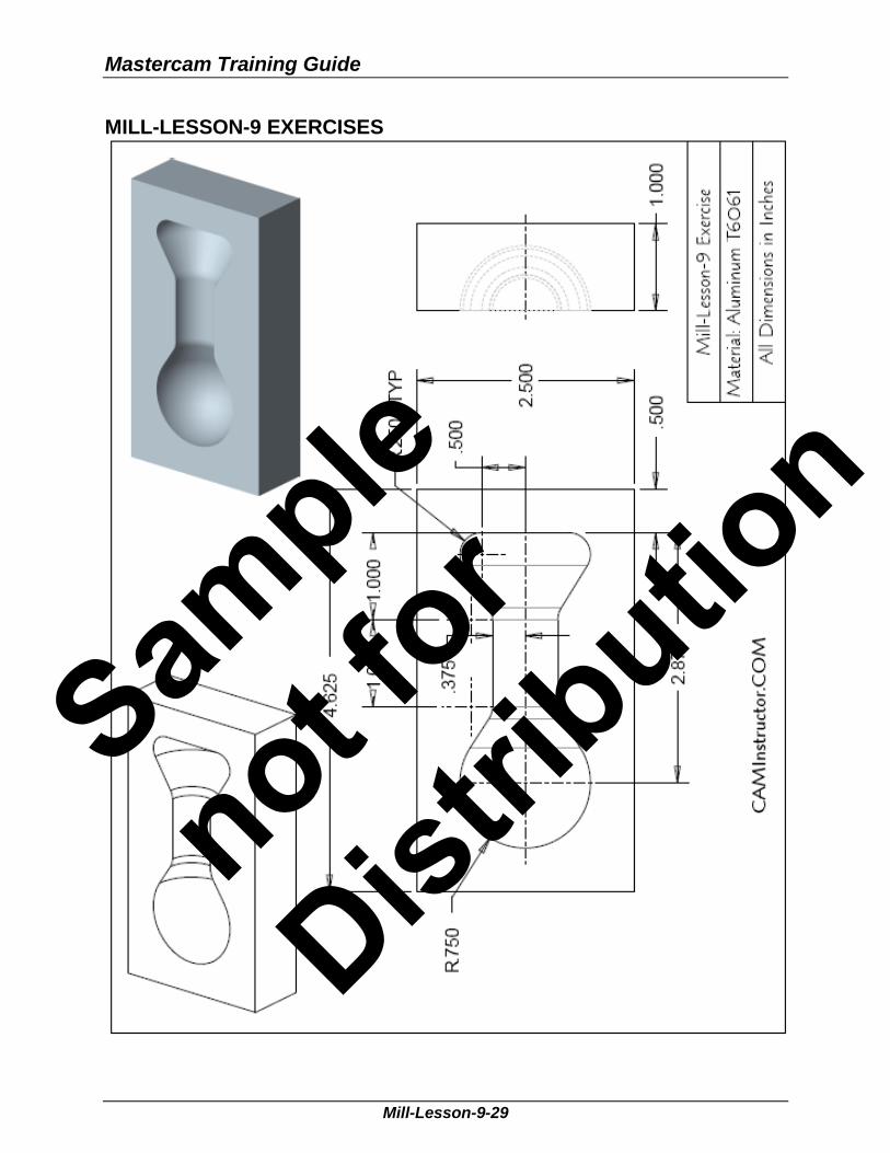
MILL-LESSON-9 EXERCISES
Sample
not for
Distrib
ution

Mill-Lesson-9
Mill-Lesson-9-30
Sample
not for
Distrib
ution

Mastercam Training Guide
Mill-Lesson-9-31
Sample
not for
Distrib
ution