
SAILOR SP3520 VHF GMDSS - Telemar Norge · Chapter 1 1 Introduction Your VHF GMDSS SP3520, your new...
44
SAILOR SP3520 VHF GMDSS USER MANUAL
Transcript of SAILOR SP3520 VHF GMDSS - Telemar Norge · Chapter 1 1 Introduction Your VHF GMDSS SP3520, your new...
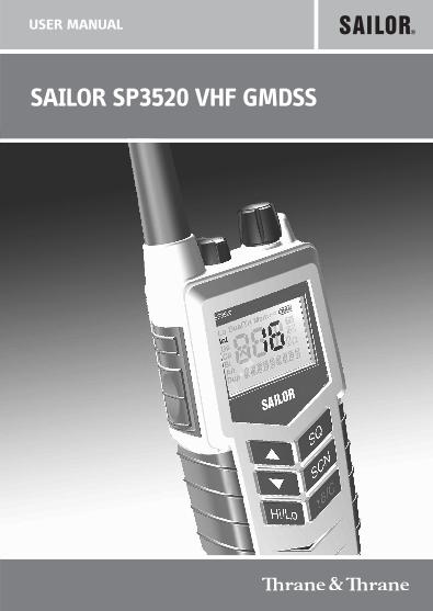
SAILOR SP3520 VHF GMDSS
USER MANUAL
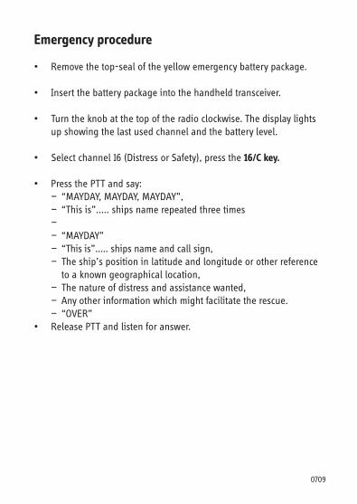
Emergency procedure
• Remove the top-seal of the yellow emergency battery package.
• Insert the battery package into the handheld transceiver.
• Turn the knob at the top of the radio clockwise. The display lights up showing the last used channel and the battery level.
• Select channel 16 (Distress or Safety), press the 16/C key.
• Press the PTT and say: — “MAYDAY, MAYDAY, MAYDAY”, — “This is”..... ships name repeated three times — — “MAYDAY” — “This is”..... ships name and call sign, — The ship’s position in latitude and longitude or other reference to a known geographical location, — The nature of distress and assistance wanted, — Any other information which might facilitate the rescue. — “OVER”• Release PTT and listen for answer.
0709
SP3520 VHF GMDSS
Document number: TT 98-124294-D
Release date: October, 2007
Copyright: © 2007 Thrane & Thrane A/S. All rights reserved.
Trademark Acknowledgements
• SAILOR is a registered trademark of Thrane & Thrane A/S.
• Other product and company names mentioned in this manual may be trademarks or trade names of their respective owners.
Warranty limitation
IMPORTANT - The radio is a sealed waterproof unit. To create and maintain its waterproof integrity it was assembled in a controlled environment using special equipment. The radio is not a user maintainable unit, and under no circumstances should the unit be opened except by authorized personnel. Unauthorized opening of the unit will invalidate the warranty.
Disclaimer
Any responsibility or liability for loss or damage in connection with the use of this product and the accompanying documentation is disclaimed by Thrane & Thrane. The information in this manual is provided for information purposes only, is subject to change without notice, may contain errors or inaccuracies, and represents no commitment whatsoever by Thrane & Thrane. This agreement is governed by the laws of Denmark.
Manuals issued by Thrane & Thrane are periodically revised and updated. Anyone relying on this information should satisfy himself/herself as to the most current version. Providers with access to Thrane & Thrane's Extranet may obtain current copies of manuals at: http://extranet.thrane.com
Thrane & Thrane is not responsible for the content or accuracy of any translations or reproductions, in whole or in part, of this manual from any other source.
i0740
ii
Precautions
Avoid water and salt in the I/O connector and keep it clean frequently.
Only use original Thrane & Thrane battery packs. Make sure they are clean and dry before attaching the transceiver. Be careful not to damage any gaskets.
Only use the original Thrane & Thrane charger for the rechargeable battery.
Be very careful when handling the Lithium batteries. With correct use they are safe but any misuse might cause dangerous situations.
Never short circuit the battery terminals, never expose the transceiver and the batteries to extreme temperature or fire and never use any kind of violence.
Avoid close contact between the antenna and parts of the human body. The top of the antenna must never be closer than 5 cm to the body when transmitting.
Do not submerge the transceiver more than 1 m for 30 minutes.
Keep the transceiver at least 0.3 m away from the magnetic compass.
0709
Training information
SAILOR SP3520 VHF GMDSS is designed for "occupational use only". It must be operated by licensed personnel only.
The SP3520 complies with the FCC RF exposure limits for "Occupational Use Only".
• FCC OET Bulletin 65 Supplement C, evaluating compliance with FCC guidelines for human exposure to radio frequency electromagnetic fields.
• American National Standards Institute (C95.1) IEEE standard for safety levels with respect to human exposure to radio frequency electromagnetic fields, 3 kHz to 300 GHz.
• American National Standards Institute (C95.3) IEEE recommended practice for the measurement of potentially hazardous electromagnetic fields - RF and microwaves.
Correct use
For best performance, hold the radio vertically and 10 cm away from the head when talking into the microphone.
Warning! Your Thrane & Thrane VHF radio generates electromagnetic RF (radio frequency) energy when transmitting. To ensure that you are not exposed to excessive amounts of energy and thus to avoid health hazards from excessive exposure to RF energy, all persons must be at least 5 cm away from the antenna when the radio is transmitting.
iii
0703
iv
0641
Contents
Chapter Introduction
Your VHF GMDSS .................................................................1
Performance .......................................................................2
Channels ............................................................................2
Chapter Operation
Controls ..............................................................................3Keys and buttons ................................................................3The display .........................................................................5
Using the VHF GMDSS ........................................................6Basic functions ...................................................................6Other functions ...................................................................9
Configuring the VHF GMDSS ..............................................10Entering and using configuration mode ............................10Configuration settings ....................................................... 11
Chapter Batteries
Battery types .....................................................................13
The primary battery ...........................................................13
The secondary battery .......................................................14Battery level indication ......................................................14Removing and inserting the battery pack ...........................14The battery charger ...........................................................15Installing the charger ........................................................15Recharging the secondary battery .....................................16
v
0643
Chapter Equipment and accessories
External equipment ........................................................... 17List of equipment ............................................................... 17Connecting external equipment ......................................... 17Impact on radio operation .................................................18Accessorie connector .........................................................18
Accessories .......................................................................19List of accessories ..............................................................19Attaching and removing the belt clip .................................21Attaching the lanyard ........................................................21
Chapter TroubleshootingDisplaying errors .............................................................. 23
App. Technical specifications
Technical data SP3520 ..................................................... 25General ............................................................................ 25Transmitter ....................................................................... 26Receiver ........................................................................... 26
Battery life guidelines ...................................................... 27Primary battery (non-rechargeable) ................................. 27Secondary battery (rechargeable) ..................................... 27
Dimensional drawing, transceiver .................................... 28
Dimensional drawing, chargers ....................................... 29
App. Attention
Goretex Membran .............................................................31
vi
0740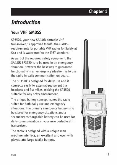
Chapter 1
Introduction
Your VHF GMDSS
SP3520, your new SAILOR portable VHF transceiver, is approved to fulfil the GMDSS requirements for portable VHF radios for Safety at Sea and is waterproof to the IP67 standard.
As part of the required safety equipment, the SAILOR SP3520 is to be used in an emergency situation. However the best way to guarantee functionality in an emergency situation, is to use the radio in daily communication on board.
The SP3520 is designed for daily use and it connects easily to external equipment like headsets and fist mikes, making the SP3520 suitable for any noisy environment.
The unique battery concept makes the radio suited for both daily use and emergency situations. The primary emergency battery is to be stored for emergency situations and a secondary rechargeable battery can be used for daily communication in your new portable VHF transceiver.
The radio is designed with a unique man machine interface, an excellent grip even with gloves, and large tactile buttons.
10641
Introduction
The display has red adjustable backlight which makes the display visible even at night.
The radio is equipped with a lanyard and a belt clip. A huge accessory program comes with the SAILOR SP3500 series.
Please find the nearest SAILOR distributor on www.thrane.com.
Performance
For best performance of the transceiver keep the following in mind:
• Keep clear of metal environment.
• Hold the transceiver vertically and 10 cm from lips and push the PTT when transmitting.
• In receive mode carry the transceiver vertically with belt clips.
• To preserve battery power, adjust squelch to close the loudspeaker when there is no signal.
• If you are in a lifeboat keep the antenna as high as possible.
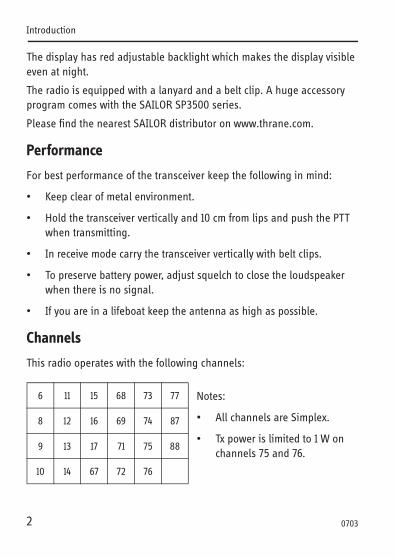
Channels
This radio operates with the following channels:
Notes:
• All channels are Simplex.
• Tx power is limited to 1 W on channels 75 and 76.
6 11 15 68 73 77
8 12 16 69 74 87
9 13 17 71 75 88
10 14 67 72 76
2 0703
Chapter 2
Operation
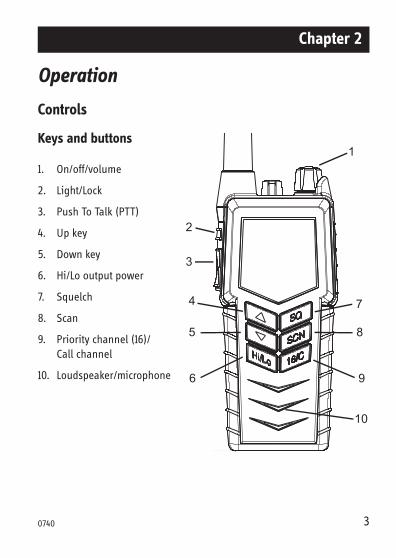
Controls
Keys and buttons
1. On/off/volume
2. Light/Lock
3. Push To Talk (PTT)
4. Up key
5. Down key
6. Hi/Lo output power
7. Squelch
8. Scan
9. Priority channel (16)/ Call channel
10. Loudspeaker/microphone
1
2
3
4
5
6
7
8
9
10
30740
Operation
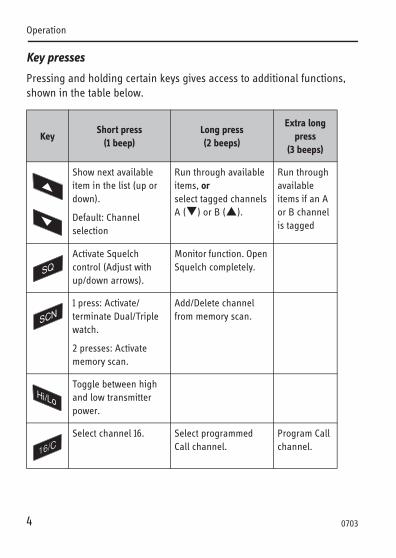
Key presses
Pressing and holding certain keys gives access to additional functions, shown in the table below.
KeyShort press
(1 beep)Long press(2 beeps)
Extra long press
(3 beeps)
Show next available item in the list (up or down).
Default: Channel selection
Run through available items, or select tagged channels A ( ) or B ( ).
Run through available items if an A or B channel is tagged
Activate Squelch control (Adjust with up/down arrows).
Monitor function. Open Squelch completely.
1 press: Activate/terminate Dual/Triple watch.
2 presses: Activate memory scan.
Add/Delete channel from memory scan.
Toggle between high and low transmitter power.
Select channel 16. Select programmed Call channel.
Program Call channel.
4 0703
Operation
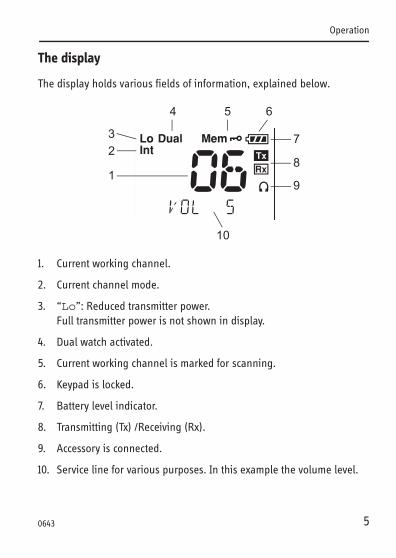
The display
The display holds various fields of information, explained below.
1. Current working channel.
2. Current channel mode.
3. “Lo”: Reduced transmitter power. Full transmitter power is not shown in display.
4. Dual watch activated.
5. Current working channel is marked for scanning.
6. Keypad is locked.
7. Battery level indicator.
8. Transmitting (Tx) /Receiving (Rx).
9. Accessory is connected.
10. Service line for various purposes. In this example the volume level.
1
3
4 5 6
7
8
9
10
2
50643
Operation
Using the VHF GMDSS
Basic functions
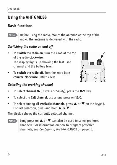
Switching the radio on and off
• To switch the radio on, turn the knob at the top of the radio clockwise. The display lights up showing the last used channel and the battery level.
• To switch the radio off, Turn the knob back counter-clockwise until it clicks.
Selecting the working channel
• To select channel 16 (Distress or Safety), press the 16/C key.
• To select the Call channel, use a long press on 16/C.
• To select among all available channels, press or on the keypad. For fast selection, press and hold or .
The display shows the currently selected channel.
Note Before using the radio, mount the antenna at the top of the radio. The antenna is delivered with the radio.
Note Long press on or can also be used to select preferred channels. For information on how to program preferred channels, see Configuring the VHF GMDSS on page 10.
6
0643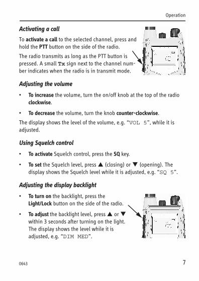
Operation
Activating a call
To activate a call to the selected channel, press and hold the PTT button on the side of the radio.
The radio transmits as long as the PTT button is pressed. A small Tx sign next to the channel num-ber indicates when the radio is in transmit mode.
Adjusting the volume
• To increase the volume, turn the on/off knob at the top of the radio clockwise.
• To decrease the volume, turn the knob counter-clockwise.
The display shows the level of the volume, e.g. “VOL 5”, while it is adjusted.
Using Squelch control
• To activate Squelch control, press the SQ key.
• To set the Squelch level, press (closing) or (opening). The display shows the Squelch level while it is adjusted, e.g. “SQ 5”.
Adjusting the display backlight
• To turn on the backlight, press the Light/Lock button on the side of the radio.
• To adjust the backlight level, press or within 3 seconds after turning on the light.The display shows the level while it is adjusted, e.g. “DIM MED”.
7
0643
Operation
Using Dual watch
To activate Dual watch, press the SCN key.The display shows “Dual” at the top and “16” at the bottom right. The radio toggles between the selected channel and channel 16.
• To terminate Dual watch, press SCN again.
Scanning channels
• To activate scanning memory, press 2 times SCN within 2 seconds. During scanning, the display shows “SC” in the channel field. The radio toggles between channel 16 and each of the channels marked for scanning.
• To terminate scanning, press SCN once.
Changing the transmitter power
To change the transmitter power, press the Hi/Lo key. The display shows “Lo” when power is set to low. Otherwise maximum power is used.
Locking the keypad
• To lock the keypad, press and hold the Light/Lock button. The display shows a key symbol when the keypad is locked.
• To unlock the keypad, press and hold the Light/Lock button again.
8
0740
Operation
Other functions
Programming the Call channel
To program the Call channel, do as follows:
1. Press and hold 16/C until the current Call channel number is flashing.
2. Select the channel with or .
3. Press 16/C to confirm.
Programming the scanning memory
To add a channel to the scanning memory, select the channel and then press and hold the SCN key until the display shows MEM at the top.
To remove a channel from the scanning memory, select the channel and then press and hold the SCN key until the MEM sign disappears from the display.
9
0740
Operation
Configuring the VHF GMDSS
Entering and using configuration mode
• To enter configuration mode, press and hold the Light/Lock button while turning on the radio.The bottom line of the display shows the current menu item/setting.
• To exit configuration mode, turn off the radio or press any key except , and the Light/Lock button.
Using the PTT button or leaving the radio inactive for 10 seconds also causes the radio to exit configuration mode.
• To change a setting, press or .
• To confirm the current setting and go to the next menu item, press the Light/Lock button.
Note The radio is not operational in configuration mode.
10
0643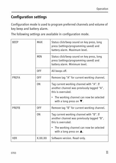
Operation
Configuration settings
Configuration mode is used to program preferred channels and volume of key beep and battery alarm.
The following settings are available in configuration mode.
BEEP MAX Status click/beep sound on key press, long press (settings/programming saved) and battery alarm. Maximum level.
MIN Status click/beep sound on key press, long press (settings/programming saved) and battery alarm. Minimum level.
OFF All beeps off.
PREFA OFF Remove tag “A” for current working channel.
ON Tag current working channel with “A”. If another channel was previously tagged “A”, this is overruled.
• The working channel can now be selected with a long press on .
PREFB OFF Remove tag “B” for current working channel.
ON Tag current working channel with “B”. If another channel was previously tagged “B”, this is overruled.
• The working channel can now be selected with a long press on .
VER X.XX.XX Software version. Read-only.
11
0703
Operation
12
0643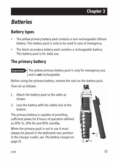
Chapter 3
Batteries
Battery types
• The yellow primary battery pack contains a non-rechargeable Lithium battery. This battery pack is only to be used in case of emergency.
• The black secondary battery pack contains a rechargeable battery. This battery pack is for daily use.
The primary battery
Before using the primary battery, remove the seal on the battery pack.
Then do as follows:
1. Attach the battery pack to the radio as shown.
2. Lock the battery with the safety lock at the bottom.
The primary battery is capable of providing sufficient power for 8 hours of operation defined as 10% Tx, 10% Rx and 80% standby.
When the primary pack is not in use it must always be placed in the dedicated rear position in the charger cradle, see The battery charger on page 15.
Important The yellow primary battery pack is only for emergency use, and is not rechargeable.
1
2
13
0709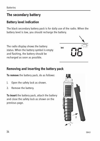
Batteries
14
The secondary battery
Battery level indication
The black secondary battery pack is for daily use of the radio. When the battery level is low, you should recharge the battery.
The radio display shows the battery status. When the battery symbol is empty and flashing, the battery should be recharged as soon as possible.
Removing and inserting the battery pack
To remove the battery pack, do as follows:
1. Open the safety lock as shown.
2. Remove the battery.
To insert the battery pack, attach the battery and close the safety lock as shown on the previous page.
1
2
0643
Batteries
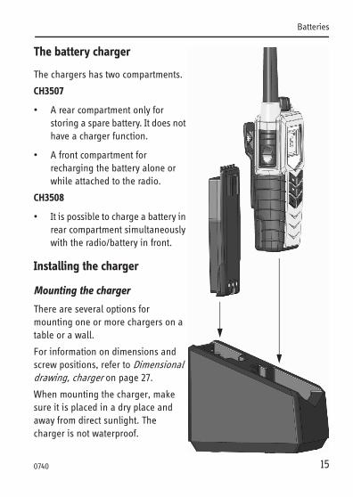
The battery charger
The chargers has two compartments.
CH3507
• A rear compartment only for storing a spare battery. It does not have a charger function.
• A front compartment for recharging the battery alone or while attached to the radio.
CH3508
• It is possible to charge a battery in rear compartment simultaneously with the radio/battery in front.
Installing the charger
Mounting the charger
There are several options for mounting one or more chargers on a table or a wall.
For information on dimensions and screw positions, refer to Dimensional drawing, charger on page 27.
When mounting the charger, make sure it is placed in a dry place and away from direct sunlight. The charger is not waterproof.
15
0740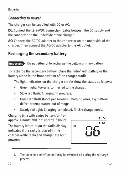
Batteries
16
Connecting to power
The charger can be supplied with DC or AC.
DC: Connect the 12-24VDC Connection Cable between the DC supply and the connector on the underside of the charger.
AC: Connect the AC/DC adapter to the connector on the underside of the charger. Then connect the AC/DC adapter to the AC outlet.
Recharging the secondary battery
To recharge the secondary battery, place the radio1 with battery or the battery alone in the front position of the charger cradle.
The light indicators on the charger cradle show the status as follows:
• Green light: Power is connected to the charger.
• Slow red flash: Charging in progress.
• Quick red flash (twice per second): Charging error, e.g. battery defect or temperature out of range.
• Steady red light: Charging completed. Trickle charge mode.
Charging time with emtpy battery: VHF off approx. 4 hours, VHF on: approx. 5 hours.
The battery indicator on the radio display indicates if the radio is placed in the charger while radio and charger are both powered.
Important Do not attempt to recharge the yellow primary battery!
1. The radio may be left on or it may be switched off during the recharge process.
0740
Chapter 4
Equipment and accessories
External equipment
List of equipment
The following equipment can be connected to the radio:
• SAVOX 400E Push-To Talk unit
• SAVOX C500 Fist Mike
• SAVOX NC/400 Noise-com
• SAVOX HC-E Helmet-com
• SAVOX K53004 Helmet unit
• Peltor MT7H79 Headset
We recommend to remove all accessories during emergency use.
All accessories listed might be used when body worn.
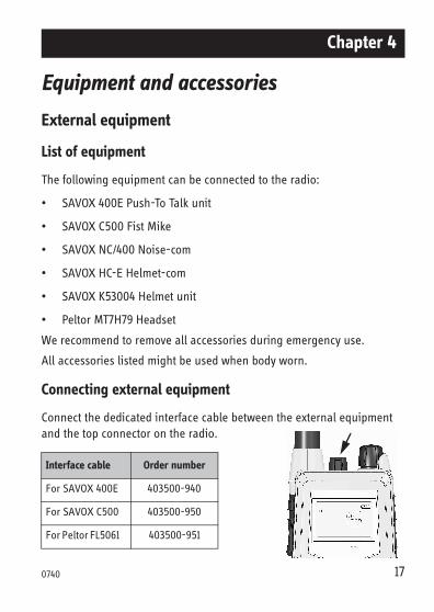
Connecting external equipment
Connect the dedicated interface cable between the external equipment and the top connector on the radio.
Interface cable Order number
For SAVOX 400E 403500-940
For SAVOX C500 403500-950
For Peltor FL5061 403500-951
170740
Equipment and accessories
18
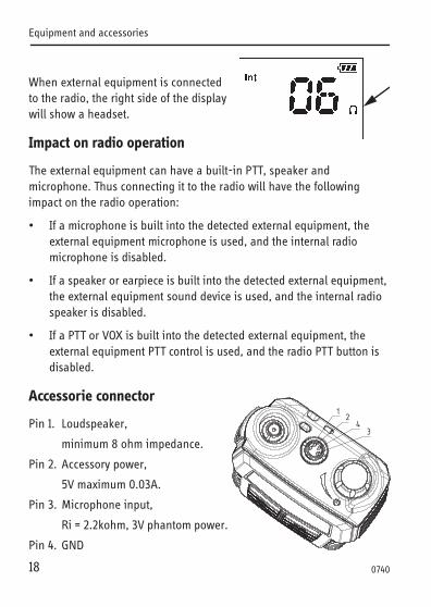
When external equipment is connected to the radio, the right side of the display will show a headset.
Impact on radio operation
The external equipment can have a built-in PTT, speaker and microphone. Thus connecting it to the radio will have the following impact on the radio operation:
• If a microphone is built into the detected external equipment, the external equipment microphone is used, and the internal radio microphone is disabled.
• If a speaker or earpiece is built into the detected external equipment, the external equipment sound device is used, and the internal radio speaker is disabled.
• If a PTT or VOX is built into the detected external equipment, the external equipment PTT control is used, and the radio PTT button is disabled.
Accessorie connector
Pin 1. Loudspeaker,
minimum 8 ohm impedance.
Pin 2. Accessory power,
5V maximum 0.03A.
Pin 3. Microphone input,
Ri = 2.2kohm, 3V phantom power.
Pin 4. GND
0740
Equipment and accessories
Accessories
List of accessories
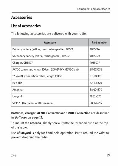
The following accessories are delivered with your radio:
Batteries, charger, AC/DC Converter and 12VDC Connection are described in Batteries on page 13.
To mount the antenna, simply screw it into the threaded bush at the top of the radio.
Use of lanyard is only for hand held operation. Put it around the wrist to prevent dropping the radio.
Accessory Part number
Primary battery (yellow, non-rechargeable), B3501 403501A
Secondary battery (black, rechargeable), B3502 403502A
Charger, CH3507 403507A
AC/DC converter, length 150cm (100-240V~ /12VDC out) 88-125538
12-24VDC Connection cable, length 150cm 37-124381
Belt clip 62-124320
Antenna 88-124370
Lanyard 41-124375
SP3520 User Manual (this manual) 98-124294
19
0740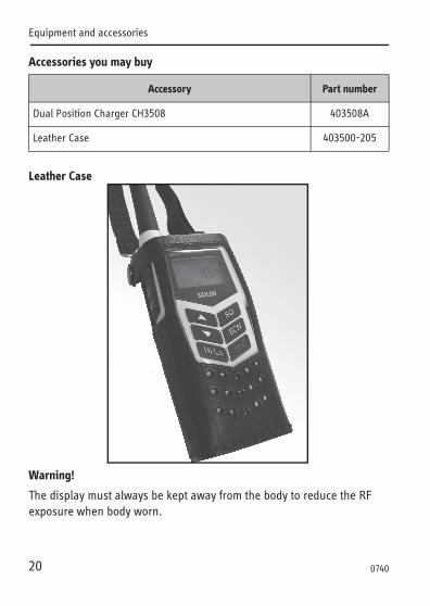
Equipment and accessories
Accessories you may buy
Leather Case
Warning!
The display must always be kept away from the body to reduce the RF exposure when body worn.
Accessory Part number
Dual Position Charger CH3508 403508A
Leather Case 403500-205
20 0740
Equipment and accessories
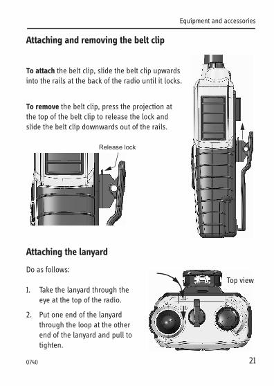
Attaching and removing the belt clip
To attach the belt clip, slide the belt clip upwards into the rails at the back of the radio until it locks.
To remove the belt clip, press the projection at the top of the belt clip to release the lock and slide the belt clip downwards out of the rails.
Attaching the lanyard
Do as follows:
1. Take the lanyard through the eye at the top of the radio.
2. Put one end of the lanyard through the loop at the other end of the lanyard and pull to tighten.
Release lock
Top view
21
0740
Equipment and accessories
22
0740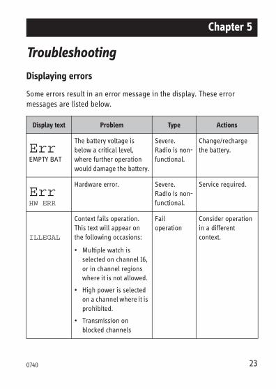
Chapter 5
Troubleshooting
Displaying errors
Some errors result in an error message in the display. These error messages are listed below.
Display text Problem Type Actions
ErrEMPTY BAT
The battery voltage is below a critical level, where further operation would damage the battery.
Severe. Radio is non-functional.
Change/recharge the battery.
ErrHW ERR
Hardware error. Severe. Radio is non-functional.
Service required.
ILLEGAL
Context fails operation. This text will appear on the following occasions:
• Multiple watch is selected on channel 16, or in channel regions where it is not allowed.
• High power is selected on a channel where it is prohibited.
• Transmission on blocked channels
Fail operation
Consider operation in a different context.
230740

Troubleshooting
24 0740
Appendix A
Technical specifications
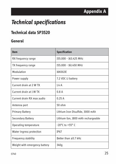
Technical data SP3520
General
Item Specification
RX frequency range 155.000 - 163.425 MHz
TX frequency range 155.000 - 161.450 MHz
Modulation 16K0G3E
Power supply 7.2 VDC Li battery
Current drain at 2 W TX 1.4 A
Current drain at 1 W TX 0.8 A
Current drain RX max audio 0.25 A
Antenna port 50 ohm
Primary Battery Lithium Iron Disulfide, 3000 mAh
Secondary Battery Lithium-Ion, 1800 mAh rechargeable
Operating temperature -20°C to +55° C
Water ingress protection IP67
Frequency stability Better than ±0.7 kHz
Weight with emergency battery 340g
250740
Technical specifications
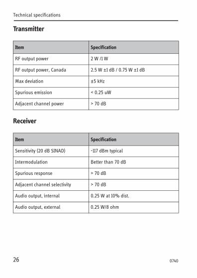
Transmitter
Receiver
Item Specification
RF output power 2 W /1 W
RF output power, Canada 2.5 W ±1 dB / 0.75 W ±1 dB
Max deviation ±5 kHz
Spurious emission < 0.25 uW
Adjacent channel power > 70 dB
Item Specification
Sensitivity (20 dB SINAD) -117 dBm typical
Intermodulation Better than 70 dB
Spurious response > 70 dB
Adjacent channel selectivity > 70 dB
Audio output, internal 0.25 W at 10% dist.
Audio output, external 0.25 W/8 ohm
26
0740
Technical specifications
Battery life guidelines
Primary battery (non-rechargeable)
The primary non-rechargeable battery pack is capable of providing sufficient power for the specified 8 hours according to regulations.
The battery is marked with an expiry date. Replace the battery at or before this date.
To ensure a long lifetime keep the battery in the store position in the charger and avoid high temperature and direct sunlight.
Secondary battery (rechargeable)
During daily use, always keep the battery fully charged and away from hot areas.
Keep the battery terminals dry and clean.
Never discharge beyond the specifications of the battery.
Operation/Standby time depends on usage. Generally, the more the radio is transmitting, the faster it will drain the battery. Also, the “Hi” power setting will drain the battery faster than the “Lo” setting.
Approximate figures are:
• A battery can be stored for 4 to 6 month at 25°C if charged to 25%.
• The battery will normally last for 5 to 9 hours of use on a fully charged battery.
Note New batteries should be placed in the charger for minimum 12 hours first time.
270709
Technical specifications
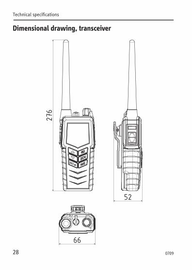
Dimensional drawing, transceiver
28
0709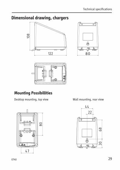
Technical specifications
Dimensional drawing, chargers
Mounting PossibillitiesDesktop mounting, top view Wall mounting, rear view
290740

Technical specifications
30 0703
Appendix B
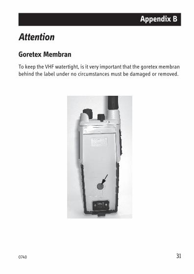
Attention
Goretex Membran
To keep the VHF watertight, is it very important that the goretex membran behind the label under no circumstances must be damaged or removed.
310740

Attention
32 0740