SAILOR 6280/6281 AIS System - Pacific Rim · SAILOR 6280/6281 AIS System Installation manual...
136
SAILOR 6280/6281 AIS System Installation manual
Transcript of SAILOR 6280/6281 AIS System - Pacific Rim · SAILOR 6280/6281 AIS System Installation manual...
SAILOR 6280/6281 AIS SystemInstallation manual

SAILOR 6280/6281 AIS System
Installation manual
Document number: 98-137573-B
Release date: November 29, 2013
ii 98-137573-B
Disclaimer
Any responsibility or liability for loss or damage in connection with the use of this product and the accompanying documentation is disclaimed by Thrane & Thrane A/S. The information in this manual is provided for information purposes only, is subject to change without notice and may contain errors or inaccuracies. Manuals issued by Thrane & Thrane A/S are periodically revised and updated. Anyone relying on this information should acquire the most current version e.g. from www.cobham.com/satcom or from the distributor. Thrane & Thrane A/S is not responsible for the content or accuracy of any translations or reproductions, in whole or in part, of this manual from any other source.
Thrane & Thrane A/S is trading as Cobham SATCOM.
Copyright
© 2013 Thrane & Thrane A/S. All rights reserved.
Trademark acknowledgements
• SAILOR is a registered trademark of Thrane & Thrane A/S in the European Union, the United States of America and other countries.
• Other product and company names mentioned in this manual may be trademarks or trade names of their respective owners.
• This product contains Android™ software (a Google Inc. trademark).
GPL notification
The software included in this product contains copyrighted software that is licensed under the GPL/LGPL. The verbatim licenses can be found online at:
http://www.gnu.org/licenses/old-licenses/gpl-2.0.html
http://www.gnu.org/licenses/old-licenses/lgpl-2.1.html
You may obtain the complete corresponding source code from us for a period of three years after our last shipment of this product, which will be no earlier than 2021, by sending a money order or check for DKK 50 to:
SW Technology/GPL Compliance,Thrane & Thrane A/S,Lundtoftegaardsvej 93D2800 LyngbyDENMARK
Please write "source for product SAILOR 6282 AIS Transponder" in the memo line of your payment. This offer is valid to anyone in receipt of this information.
98-137573-B iii
Safety summaryObserve the following general safety precautions during all phases of operation, service and repair of this equipment. Failure to comply with these precautions or with specific warnings elsewhere in this manual violates safety standards of design, manufacture and intended use of the equipment. Thrane & Thrane A/S assumes no liability for the customer's failure to comply with these requirements.
Ground the equipmentTo minimise shock hazard, connect the SAILOR 6282 AIS Transponder to an electrical ground and follow the cable instructions.
RF exposure hazards and instructionsThe SAILOR unit generates electromagnetic RF energy when transmitting. To ensure that you and those around you are not exposed to excessive amounts of energy and to avoid health hazards from excessive exposure to RF energy, all persons must be at least 0.2 m away from the antenna when the unit is transmitting.
Warranty limitationIMPORTANT - The SAILOR 6285 GPS Antenna – Active is a sealed waterproof unit (classified IPx6 & IPx8). To create and maintain its waterproof integrity it was assembled in a controlled environment using special equipment. The SAILOR 6282 AIS Transponder is not a user maintainable unit, and under no circumstances should the unit be opened except by authorized personnel. Unauthorized opening of the unit will invalidate the warranty.
Installation and serviceInstallation and general service must be done by skilled service personnel.
Compass safe distanceCompass safe distance: 55 cm (Standard magnetic compass), 45 cm (Emergency magnetic compass) from the SAILOR 6282 AIS Transponder or the SAILOR 6283 AIS Connection Box and Wall Tray.
iv 98-137573-B
Preface
Approvals
The SAILOR 6282 AIS Transponder fulfills the requirements of the Marine Equipment Directive 96/98/EC with 8th amend 2012/32/EU and is intended for use in maritime environment.
The SAILOR 6282 AIS Transponder is approved to MED 2011/75/EU and fulfills the requirements in the standards: IEC 61993-2 (2012), IEC 60945 ed.4 (2002), ITU-R M.1371-4, IEC 61162-1 (2010), IEC61162-2 (1999).
The SAILOR 6282 AIS Transponder is approved to FCC CFR47 part 80 with USCG approval no. 165.155/0168/BABT/MED000046/0575.
The SAILOR 6282 AIS Transponder is approved to IC and fulfills the requirements in RSS-182.
The approvals of the SAILOR 6282 AIS Transponder are constantly monitored. New national approvals will be applied for and granted and new test standards may come into force. Therefore the above list may not be complete. Contact your authorized dealer for more information.
98-137573-B v
Training information
The SAILOR 6282 AIS Transponder is designed for occupational use only and is also classified as such. It must only be used in the course of employment by individuals aware of the hazards as well as the way to minimize those hazards.
The unit is thus NOT intended for use in an uncontrolled environment by general public. The SAILOR 6282 AIS Transponder has been tested and complies with the FCC RF exposure limits for Occupational Use Only. The unit also complies with the following guidelines and standards regarding RF energy and electromagnetic energy levels including the recommended levels for human exposure:
• FCC OET Bulletin 65 Supplement C, evaluating compliance with FCC guidelines for human exposure to radio frequency electromagnetic fields.
• American National Standards Institute (C95.1) IEEE standard for safety levels with respect to human exposure to radio frequency electromagnetic fields, 3 kHz to 300 GHz.
• American National Standards Institute (C95.3) IEEE recommended practice for the measurement of potentially hazardous electromagnetic fields - RF and microwaves.
Below is a description of the RF exposure hazards and instructions in safe operation of the unit within the FCC RF exposure limits established for it.
Warning
Your SAILOR unit generates electromagnetic RF (radio frequency) energy when it is transmitting. To ensure that you and those around you are not exposed to excessive amounts of that energy (beyond FCC allowable limits for occupational use) and thus to avoid health hazards from excessive exposure to RF energy, FCC OET bulletin 65 establishes a Maximum Permissible Exposure (MPE) radius of 0.2 m for the maximum power of your unit (12.5 W selected) with a half wave omni-directional antenna having a maximum gain of 3 dB (5.2 dBi). This means all persons must be at least 0.2 m away from the antenna when the unit is transmitting.
Alerte de Sécurité
Dangers liés á l'exposition aux fréquences radio et instructions. Conformément á la réglementation d'industrie Canada, le present radio emetteur ne peut fonctionner qu'avec une antenne de type omnidirectionelle, demi-onde ou d'un gain maximale de 3 dB, approuvée par Industrie Canada. Pour éviter les risques pour la santé dûs á une exposition excessive aux champs de fréquences radio, une distance minimale de 0.2 m est nécessaire entre l'utilisateur et le radio-émetteur.
Installation
The SAILOR 6282 AIS Transponder is designed for installation by a skilled service person.
1. An omni-directional antenna with a maximum power gain of 5.2 dBi must be mounted at least 2.2 m above the highest deck where people may be staying during radio transmissions. The distance is to be measured vertically from the lowest point of the antenna. This provides the minimum separation distance which is in compliance with RF exposure requirements and is based on the MPE radius of 0.2 m plus the 2 m height of an adult.
2. On vessels that cannot fulfill requirements in item 1, the antenna must be mounted so that its lowest point is at least 0.2 m vertically above the heads of people on deck and all persons must be outside the 0.2 m MPE radius during radio transmission.• Always mount the antenna at least 0.2 m from possible human access.
vi 98-137573-B
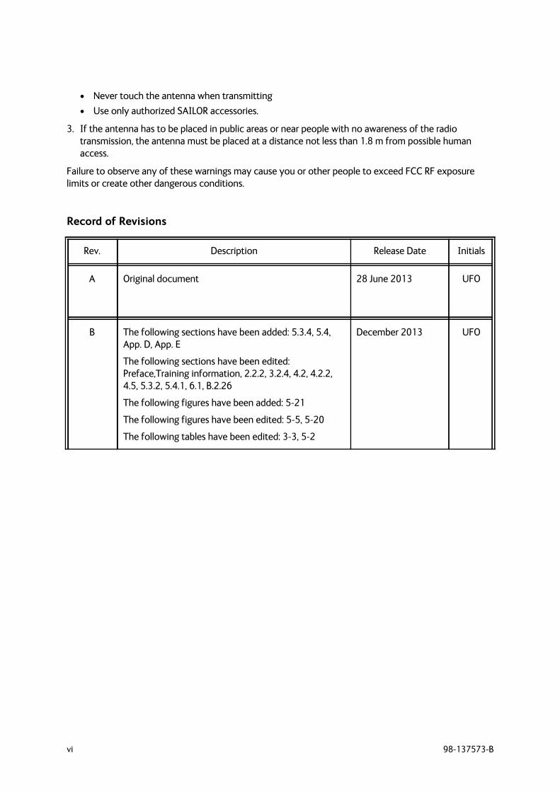
• Never touch the antenna when transmitting• Use only authorized SAILOR accessories.
3. If the antenna has to be placed in public areas or near people with no awareness of the radio transmission, the antenna must be placed at a distance not less than 1.8 m from possible human access.
Failure to observe any of these warnings may cause you or other people to exceed FCC RF exposure limits or create other dangerous conditions.
Record of Revisions
Rev. Description Release Date Initials
A Original document 28 June 2013 UFO
B The following sections have been added: 5.3.4, 5.4, App. D, App. E
The following sections have been edited: Preface,Training information, 2.2.2, 3.2.4, 4.2, 4.2.2, 4.5, 5.3.2, 5.4.1, 6.1, B.2.26
The following figures have been added: 5-21
The following figures have been edited: 5-5, 5-20
The following tables have been edited: 3-3, 5-2
December 2013 UFO
98-137573-B vii
Table of contents
Chapter 1 About this manual1.1 Intended readers ..............................................................................................................1-1
1.2 Manual overview ...............................................................................................................1-1
1.3 Related documentation ...............................................................................................1-1
1.4 Precautions ............................................................................................................................1-2
Chapter 2 Introduction2.1 Introduction to AIS ........................................................................................................2-12.1.1 Overview ..................................................................................................................................2-12.1.2 AIS applications and purpose ........................................................................................2-22.1.3 AIS classes ..............................................................................................................................2-3
2.2 SAILOR 6280/6281 AIS System ............................................................................2-32.2.1 Overview of a SAILOR 6281 AIS Basic System ....................................................2-32.2.2 Features ...................................................................................................................................2-4
2.3 System components .......................................................................................................2-52.3.1 SAILOR 6282 AIS Transponder ....................................................................................2-52.3.2 SAILOR 6285 GPS Antenna - Active ..........................................................................2-52.3.3 SAILOR 6004 Control panel ...........................................................................................2-62.3.4 SAILOR 6283 AIS Connection Box and Wall Tray (optional) ........................2-6
2.4 Part numbers and options .........................................................................................2-72.4.1 Applicable part numbers ..................................................................................................2-72.4.2 Accessories .............................................................................................................................2-7
Chapter 3 Installation3.1 Unpacking and initial inspection ..........................................................................3-13.1.1 Unpacking ...............................................................................................................................3-13.1.2 Initial inspection ..................................................................................................................3-1
3.2 VHF and GPS antenna installation ......................................................................3-23.2.1 Combined VHF and GPS antenna ................................................................................3-23.2.2 Cable requirements ............................................................................................................3-33.2.3 VHF RX/TX antenna ............................................................................................................3-43.2.4 SAILOR 6285 GPS Antenna - Active ..........................................................................3-5
3.3 Physical installation of the SAILOR 6280 AIS System .......................3-63.3.1 SAILOR 6280 AIS System - wiring ...........................................................................3-103.3.2 Cable specifications ........................................................................................................3-11
3.4 Physical installation of the SAILOR 6281 AIS System ....................3-123.4.1 SAILOR 6181 AIS Basic System - wiring ...............................................................3-17
3.5 Physical installation of the SAILOR 6004 Control panel ................3-18
Table of contents
viii 98-137573-B
Chapter 4 Interface description4.1 Power .........................................................................................................................................4-14.1.1 Connecting DC power .......................................................................................................4-2
4.2 Sensor input .........................................................................................................................4-34.2.1 Electrical characteristics ...................................................................................................4-34.2.2 Sensor configuration .........................................................................................................4-44.2.3 Position (GNS, RMC, DTM, GGA) .................................................................................4-44.2.4 Heading (HDT) ......................................................................................................................4-54.2.5 Rate of Turn (ROT) ..............................................................................................................4-54.2.6 Log (VBW) ...............................................................................................................................4-5
4.3 Presentation Interfaces ..............................................................................................4-64.3.1 Overview ..................................................................................................................................4-64.3.2 Electrical Characteristics ..................................................................................................4-74.3.3 Configuration of the Presentation Interfaces .......................................................4-74.3.4 Pilot plug connection ........................................................................................................4-8
4.4 Alarm relay ............................................................................................................................4-9
4.5 Low power forced control 1 W ..............................................................................4-9
4.6 Blue sign input .................................................................................................................4-104.6.1 Electrical interface ...........................................................................................................4-104.6.2 Configuration of Blue sign input ...............................................................................4-11
4.7 Ethernet interfaces ......................................................................................................4-114.7.1 Ethernet configuration ..................................................................................................4-11
Chapter 5 Configuration5.1 Start up .....................................................................................................................................5-15.1.1 To Power on and off ..........................................................................................................5-15.1.2 Dim and night mode ..........................................................................................................5-1
5.2 AIS app installation and system settings ......................................................5-25.2.1 System app .............................................................................................................................5-25.2.2 AIS app – daily use .............................................................................................................5-4
5.3 Configuration with the Service Interface .....................................................5-45.3.1 Accessing the Service Interface ...................................................................................5-45.3.2 General settings ...................................................................................................................5-85.3.3 Long Range ..........................................................................................................................5-105.3.4 Inland Waterways ............................................................................................................5-115.3.5 Password settings .............................................................................................................5-135.3.6 Interface settings .............................................................................................................5-145.3.7 Read logs ..............................................................................................................................5-205.3.8 System control ..................................................................................................................5-215.3.9 Reboot device ....................................................................................................................5-225.3.10 Connecting a chart plotter ..........................................................................................5-22
5.4 Configuration with the SAILOR 6004 Control Panel .........................5-225.4.1 Static Data ...........................................................................................................................5-235.4.2 Connection ..........................................................................................................................5-25
Table of contents
98-137573-B ix
5.1 Verification .........................................................................................................................5-265.1.1 NMEA Trace tool ..............................................................................................................5-26
Chapter 6 Service & maintenance6.1 Contact for support ........................................................................................................6-1
6.2 Maintenance .........................................................................................................................6-16.2.1 Preventive maintenance ..................................................................................................6-16.2.2 Error messages ......................................................................................................................6-26.2.3 Software update using the TMA (ThraneLINK Management Application) 6-2
6.3 Disassembling ......................................................................................................................6-36.3.1 Removing the SAILOR 6282 AIS Transponder from the wall tray ..............6-3
6.4 Alarms and notifications ............................................................................................6-56.4.1 Overview ..................................................................................................................................6-56.4.2 List of alarms ..........................................................................................................................6-6
6.5 Troubleshooting guide ...............................................................................................6-126.5.1 Recovering communication with the SAILOR 6004 Control Panel ..........6-13
6.6 Warranty and returning units for repair ......................................................6-146.6.1 Repacking for shipment ................................................................................................6-14
Appendix A Technical specificationsA.1 SAILOR 6282 AIS Transponder ............................................................................ A-1A.1.1 Reporting Intervals ............................................................................................................ A-2
A.2 SAILOR 6285 GPS Antenna - Active ................................................................. A-3
A.3 SAILOR 6283 AIS Connection Box and Wall Tray ................................. A-4
A.4 SAILOR 6004 Control Panel .................................................................................... A-4
Appendix B NMEA sentencesB.1 NMEA sentences used ..................................................................................................B-1B.1.1 Light weight Ethernet - LWE ..........................................................................................B-1B.1.2 Sentence characteristics and their linkage with port configuration ...........B-1
B.2 Sentence use reference ...............................................................................................B-3B.2.1 Overview of supported sentences ..............................................................................B-3B.2.2 ABK - AIS addressed and binary broadcast acknowledgement (output) .B-4B.2.3 ABM - AIS addressed binary and safety related message (input) ................B-4B.2.4 ACA - AIS channel assignment message (input / output) ...............................B-5B.2.5 ACK - Acknowledge alarm (input) ...............................................................................B-5B.2.6 AIR - AIS interrogation request (input) ....................................................................B-6B.2.7 ALR - Set alarm state (output) .......................................................................................B-6B.2.8 BBM - AIS broadcast binary message (input) ........................................................B-6B.2.9 DTM - Datum reference (input) ...................................................................................B-7B.2.10 EPV - Command or report equipment property value (input/response output) B-7B.2.11 GBS - GNSS satellite fault detection (input) ...........................................................B-7B.2.12 GGA - Global positioning system (GPS) fix data (input) ...................................B-8
Table of contents
x 98-137573-B
B.2.13 GNS - Fix data (input) ........................................................................................................B-8B.2.14 HBT - Heartbeat supervision sentence (input) ......................................................B-9B.2.15 HDT - Heading true (input) .............................................................................................B-9B.2.16 LR1 - AIS long-range reply sentence 1 (output) ...................................................B-9B.2.17 LR2 - AIS long-range reply sentence 2 (output) ................................................B-10B.2.18 LR3 - AIS long-range reply sentence 3 (output) ................................................B-10B.2.19 LRF - AIS long-range function (input / output) ..................................................B-11B.2.20 LRI - AIS long-range interrogation (input / output) .........................................B-11B.2.21 NAK - Negative acknowledgement (output) .......................................................B-11B.2.22 PIWWIVD - Inland Waterway voyage data (input / output) ......................B-12B.2.23 PIWWSSD - Inland Waterway Static Ship data (input / output) ...............B-13B.2.24 PTHRAOC - AIS operational control (input / output) ......................................B-13B.2.25 PTHRROS - Radio operational status (output) ....................................................B-14B.2.26 RMC - Recommended minimum specific GNSS data (input) ......................B-15B.2.27 ROT - Rate of turn (input) .............................................................................................B-15B.2.28 SPW - Security password sentence (input) ..........................................................B-15B.2.29 SSD - AIS ship static data (input / output) ...........................................................B-16B.2.30 THS -True heading and status (input) ....................................................................B-16B.2.31 TRL - AIS transmitter non functioning log (output) ........................................B-16B.2.32 TXT - Text transmission (output) .............................................................................B-17B.2.33 VBW - Dual ground/water speed (input) ...............................................................B-17B.2.34 VDM - AIS VHF data-link message (output) ........................................................B-17B.2.35 VDO - AIS VHF data-link own-vessel report (output) .....................................B-18B.2.36 VER - Version (output) ...................................................................................................B-18B.2.37 VSD - AIS voyage static data (input / output) ....................................................B-18B.2.38 VTG - Course over ground and ground speed (input) ....................................B-19B.2.39 ZDA - Time and Date (output) ...................................................................................B-19
Appendix C Supported keysC.1 Keys supported by the SAILOR 6004 Control Panel ............................ C-1
Appendix D Ship typesD.1 Supported ship types ................................................................................................... D-1D.1.1 Identifiers to report the ship type ............................................................................. D-1
Appendix E Talker IDE.1 Talker device and identifier ......................................................................................E-1
Glossary ..............................................................................................................................................................Glossary-1
Index ................................................................................................................................................................... Index-1
98-137573-B 1-1
Chapter 11111
Abou
t thi
s man
ual
About this manual 1
1.1 Intended readersThis is an installation manual for the SAILOR 6280/6281 AIS System. It is intended for installers of the system and service personnel. Personnel installing or servicing the system must be properly trained by Cobham SATCOM. It is important that you observe all safety requirements listed in the beginning of this manual, and install the system according to the guidelines in this manual. For daily use see the SAILOR 6282 AIS Transponder User manual.
1.2 Manual overviewThis manual has the following chapters and appendices:
• Introduction
• Installation
• Interface description
• Configuration
• Service & maintenance
• Technical specifications
• NMEA sentences
• Supported keys
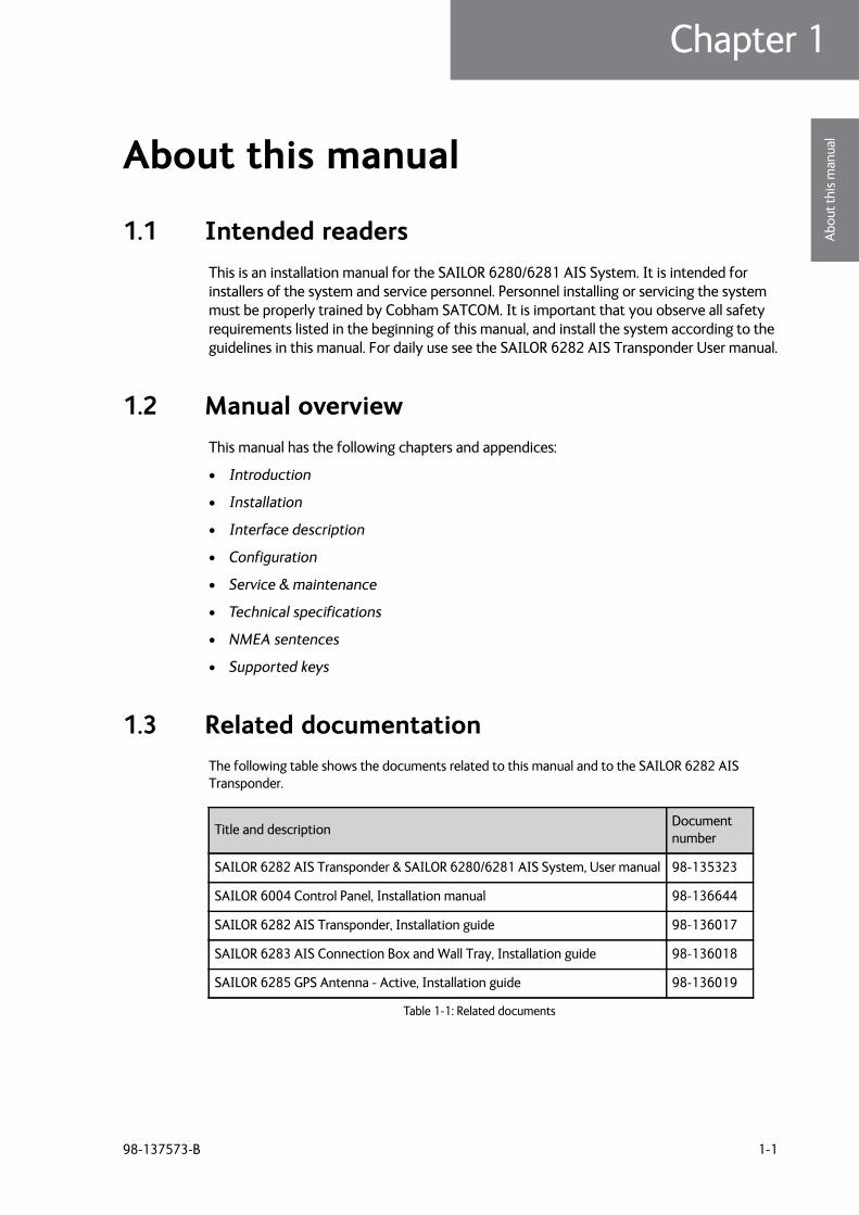
1.3 Related documentationThe following table shows the documents related to this manual and to the SAILOR 6282 AIS Transponder.
Title and description Document number
SAILOR 6282 AIS Transponder & SAILOR 6280/6281 AIS System, User manual 98-135323
SAILOR 6004 Control Panel, Installation manual 98-136644
SAILOR 6282 AIS Transponder, Installation guide 98-136017
SAILOR 6283 AIS Connection Box and Wall Tray, Installation guide 98-136018
SAILOR 6285 GPS Antenna - Active, Installation guide 98-136019
Table 1-1: Related documents
Precautions
1-2 Chapter 1: About this manual 98-137573-B
1.4 Precautions
Warnings, Cautions and Notes
Text marked with “Warning”, “Caution”, “Note” or “Important” show the following type of data:
• Warning: A Warning is an operation or maintenance procedure that, if not obeyed, can cause injury or death, or jeopardize the safety on board.
• Caution: A Caution is an operation or maintenance procedure that, if not obeyed, can cause damage to the equipment.
• Note: A Note gives information to help the reader.
• Important: A text marked Important gives information that is important to the user, e.g. to make the system work properly. This text does not concern damage on equipment, travel safety nor personal safety.
General precautions
All personnel who operate equipment or do maintenance as specified in this manual must know and follow the safety precautions. The warnings and cautions that follow apply to all parts of this manual.
CAUTION! Do not use materials that are not equivalent to materials specified by Cobham SATCOM. Materials that are not equivalent can cause damage to the equipment.
CAUTION! The system contains items that are electrostatic discharge sensitive. Use approved industry precautions to keep the risk of damage to a minimum when you touch, remove or insert parts or assemblies.
98-137573-B 2-1
Chapter 22222
Intr
oduc
tion
Introduction 2
This chapter has the following sections:
• Introduction to AIS
• SAILOR 6280/6281 AIS System
• System components
• Part numbers and options
2.1 Introduction to AIS
2.1.1 Overview
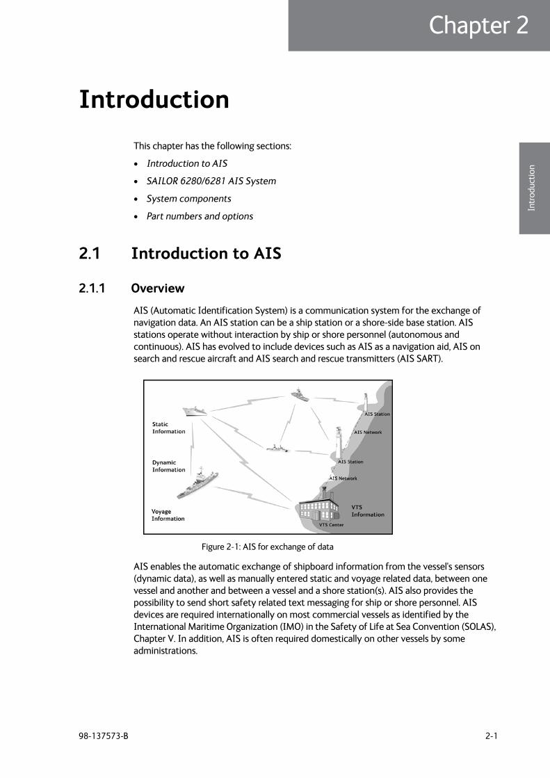
AIS (Automatic Identification System) is a communication system for the exchange of navigation data. An AIS station can be a ship station or a shore-side base station. AIS stations operate without interaction by ship or shore personnel (autonomous and continuous). AIS has evolved to include devices such as AIS as a navigation aid, AIS on search and rescue aircraft and AIS search and rescue transmitters (AIS SART).
AIS enables the automatic exchange of shipboard information from the vessel's sensors (dynamic data), as well as manually entered static and voyage related data, between one vessel and another and between a vessel and a shore station(s). AIS also provides the possibility to send short safety related text messaging for ship or shore personnel. AIS devices are required internationally on most commercial vessels as identified by the International Maritime Organization (IMO) in the Safety of Life at Sea Convention (SOLAS), Chapter V. In addition, AIS is often required domestically on other vessels by some administrations.
Figure 2-1: AIS for exchange of data
Introduction to AIS
2-2 Chapter 2: Introduction 98-137573-B
2.1.2 AIS applications and purpose
The principal applications of AIS are:
• Information exchange between vessels within VHF range of each other, increasing situation awareness
• Information exchange between a vessel and a shore station, such as a Vessel Traffic Service (VTS), to improve traffic management in congested waterways
• Automatic reporting in areas of mandatory and voluntary reporting
• Exchange of safety related information between vessels and between vessels and shore station(s).
The purpose of AIS is to improve the safety of navigation and protection of the environment by assisting in the effective navigation of ships and the operation of VTS. This is achieved through the following:
• In a ship-to-ship mode for collision avoidance
• As a means for littoral states to obtain information about a ship and its cargo
• As a VTS tool, i.e. ship-to-shore, for traffic management
• Increased situational awareness which enables effective response to emergencies such as search and rescue (SAR) as well as environmental pollution
• Providing data to identify trends or improvements to enhance navigational safety.
If a vessel operating in a mandatory ship reporting system does switch off its AIS, this should be reported to the relevant authority. Note that some data is entered or updated manually, meaning that there is potential for false entry and for the entered data to become out of date. This includes data related to static information (e.g. ship identity, dimension) and voyage related data (e.g. navigational status).
AIS and radar
A difference between AIS and radar is that AIS uses an absolute referencing system to determine the position, whereas radar determines the position by relative measurements from the vessel or shore base to observed targets. AIS may be used together with radar information to provide:
• Vessel identification, heading, course over ground (COG) and speed over ground (SOG)
• Improved vessel tracking (no target swap)
• Wider geographical coverage
• Greater positional accuracy, dependent on the position input sensor
• Information in radar shadow area ('sees' around bends and behind islands)
• Maneuver data in nearly real time
• No loss of targets in sea, rain and snow clutter
Note Not all ships are required to have AIS. Furthermore, AIS may be switched off if there is a potential risk that the operation of AIS might compromise the safety or security of the ship, or if security incidents are imminent.
SAILOR 6280/6281 AIS System
98-137573-B Chapter 2: Introduction 2-3
2222
Intr
oduc
tion
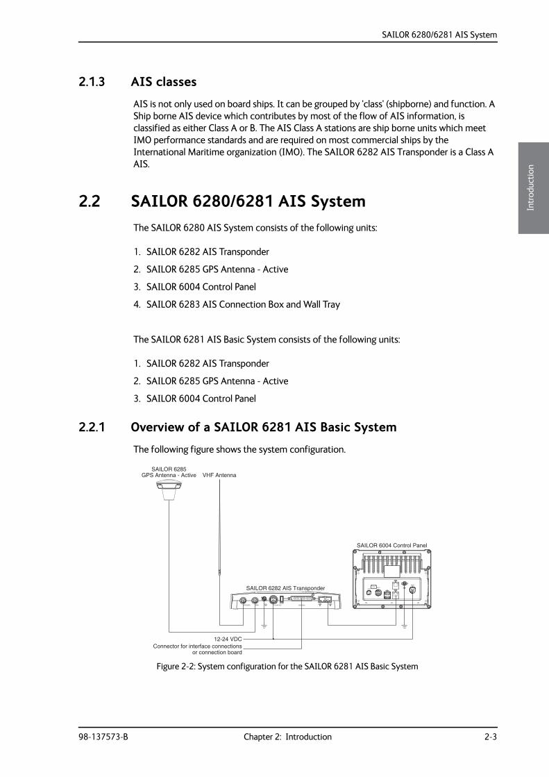
2.1.3 AIS classes
AIS is not only used on board ships. It can be grouped by 'class' (shipborne) and function. A Ship borne AIS device which contributes by most of the flow of AIS information, is classified as either Class A or B. The AIS Class A stations are ship borne units which meet IMO performance standards and are required on most commercial ships by the International Maritime organization (IMO). The SAILOR 6282 AIS Transponder is a Class A AIS.
2.2 SAILOR 6280/6281 AIS SystemThe SAILOR 6280 AIS System consists of the following units:
1. SAILOR 6282 AIS Transponder
2. SAILOR 6285 GPS Antenna - Active
3. SAILOR 6004 Control Panel
4. SAILOR 6283 AIS Connection Box and Wall Tray
The SAILOR 6281 AIS Basic System consists of the following units:
1. SAILOR 6282 AIS Transponder
2. SAILOR 6285 GPS Antenna - Active
3. SAILOR 6004 Control Panel
2.2.1 Overview of a SAILOR 6281 AIS Basic System
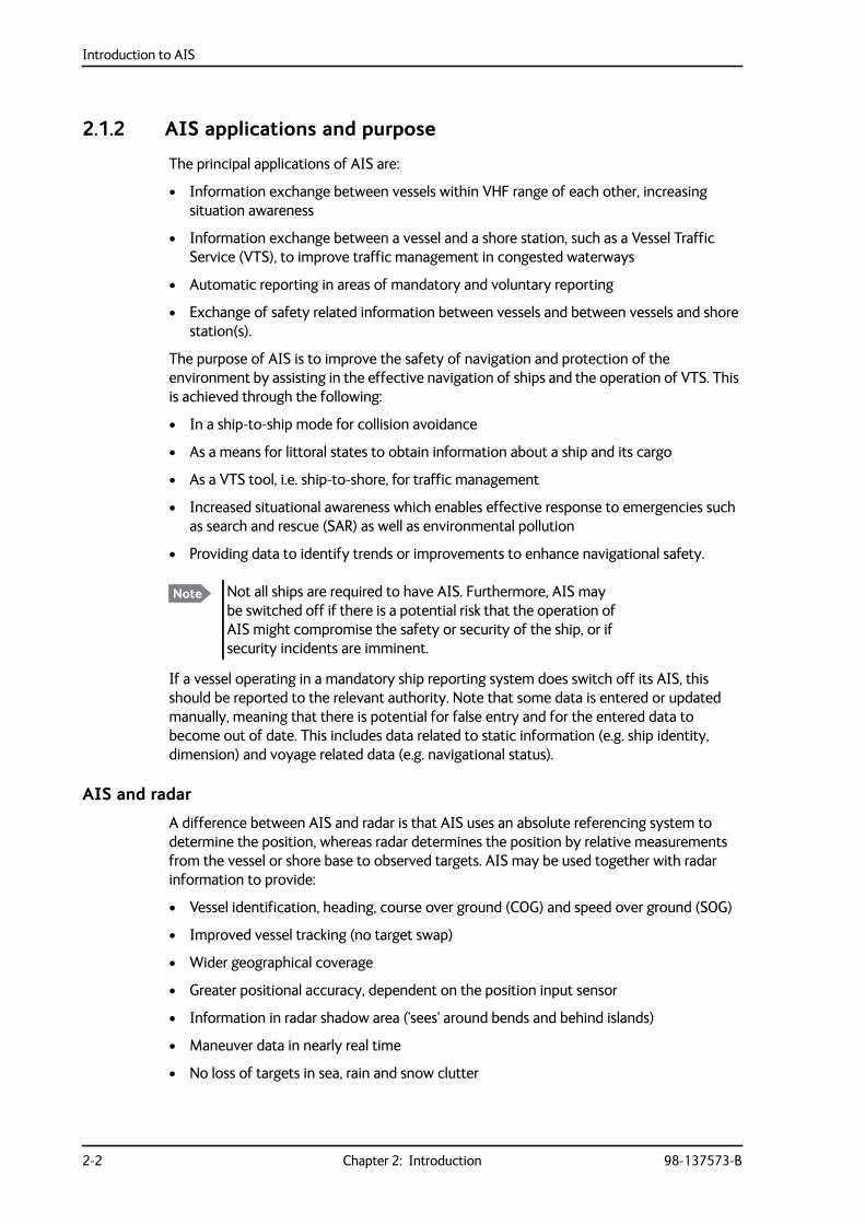
The following figure shows the system configuration.
Figure 2-2: System configuration for the SAILOR 6281 AIS Basic System
GPS Antenna - Active
SAILOR 6004 Control Panel
VHF Antenna
12-24 VDCConnector for interface connections
VHF/GPS GPS 12-24V DCFUSE
SUB-D50
1
SAILOR 6282 AIS Transponder
or connection board
SAILOR 6285
ACCAUX
TESTPWR
SAILOR 6280/6281 AIS System
2-4 Chapter 2: Introduction 98-137573-B
The SAILOR 6004 Control Panel is connected to the SAILOR 6282 AIS Transponder through a LAN connection (LWE/IEC 61162-450), here after called LWE. The SAILOR 6281 AIS Basic System is operated using the touch display of the SAILOR 6004 Control Panel.
2.2.2 Features
• AIS Class A compliant and approved
• Active GPS antenna included
• Interface for ThraneLINK applications and INS available
• Programmable interface for connection to sensors using the NMEA interface versions 2.0, ...,4.1
• Touch screen on the SAILOR 6004 Control Panel
• Easy installation with the dedicated connection box available (SAILOR 6283 AIS Connection Box and Wall Tray)
• Easy service - on the unit, through the ThraneLINK Management Application (TMA) or a web browser
• Built-in self-diagnostic system
• Built-in DC output on GPS antenna connector
• Possibility for a combined VHF and GPS antenna
• River use compliant with CCNR requirements
• Works with both GPS and GLONASS
• Input for Low Power Forced Control, 1W output (gas alarm)
• Support of Class B carrier sense messages
• Function for discarding Class B messages
• Support for Long Range satellite tracking on channel 75 & channel 76
• Interface for pilot plug
System components
98-137573-B Chapter 2: Introduction 2-5
2222
Intr
oduc
tion
2.3 System components
2.3.1 SAILOR 6282 AIS Transponder
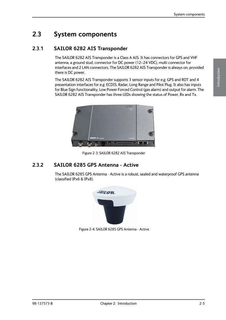
The SAILOR 6282 AIS Transponder is a Class A AIS. It has connectors for GPS and VHF antenna, a ground stud, connector for DC power (12–24 VDC), multi connector for interfaces and 2 LAN connectors. The SAILOR 6282 AIS Transponder is always on, provided there is DC power.
The SAILOR 6282 AIS Transponder supports 3 sensor inputs for e.g. GPS and ROT and 4 presentation interfaces for e.g. ECDIS, Radar, Long Range and Pilot Plug. It also has inputs for Blue Sign functionality, Low Power Forced Control (gas alarm) and output for alarm. The SAILOR 6282 AIS Transponder has three LEDs showing the status of Power, Rx and Tx.
2.3.2 SAILOR 6285 GPS Antenna - Active
The SAILOR 6285 GPS Antenna - Active is a robust, sealed and waterproof GPS antenna (classified IPx6 & IPx8).
Figure 2-3: SAILOR 6282 AIS Transponder
Figure 2-4: SAILOR 6285 GPS Antenna - Active
System components
2-6 Chapter 2: Introduction 98-137573-B
2.3.3 SAILOR 6004 Control panel
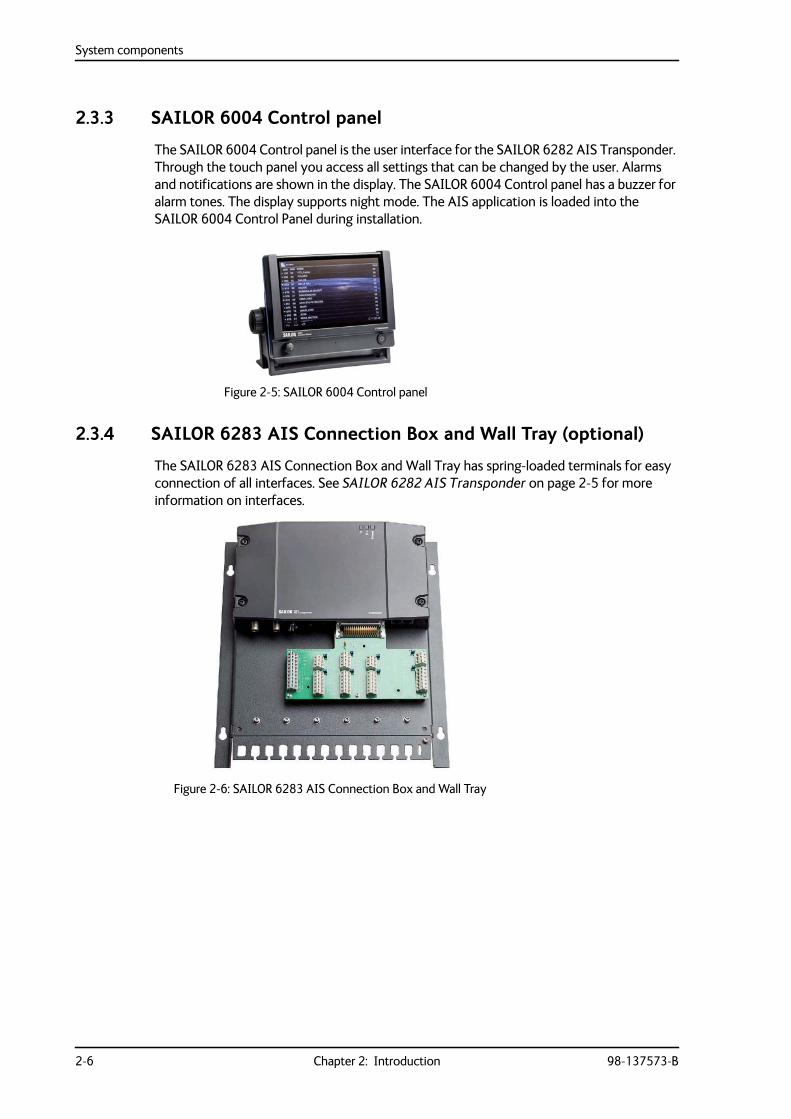
The SAILOR 6004 Control panel is the user interface for the SAILOR 6282 AIS Transponder. Through the touch panel you access all settings that can be changed by the user. Alarms and notifications are shown in the display. The SAILOR 6004 Control panel has a buzzer for alarm tones. The display supports night mode. The AIS application is loaded into the SAILOR 6004 Control Panel during installation.
2.3.4 SAILOR 6283 AIS Connection Box and Wall Tray (optional)
The SAILOR 6283 AIS Connection Box and Wall Tray has spring-loaded terminals for easy connection of all interfaces. See SAILOR 6282 AIS Transponder on page 2-5 for more information on interfaces.
Figure 2-5: SAILOR 6004 Control panel
Figure 2-6: SAILOR 6283 AIS Connection Box and Wall Tray
Part numbers and options
98-137573-B Chapter 2: Introduction 2-7
2222
Intr
oduc
tion
2.4 Part numbers and options
2.4.1 Applicable part numbers
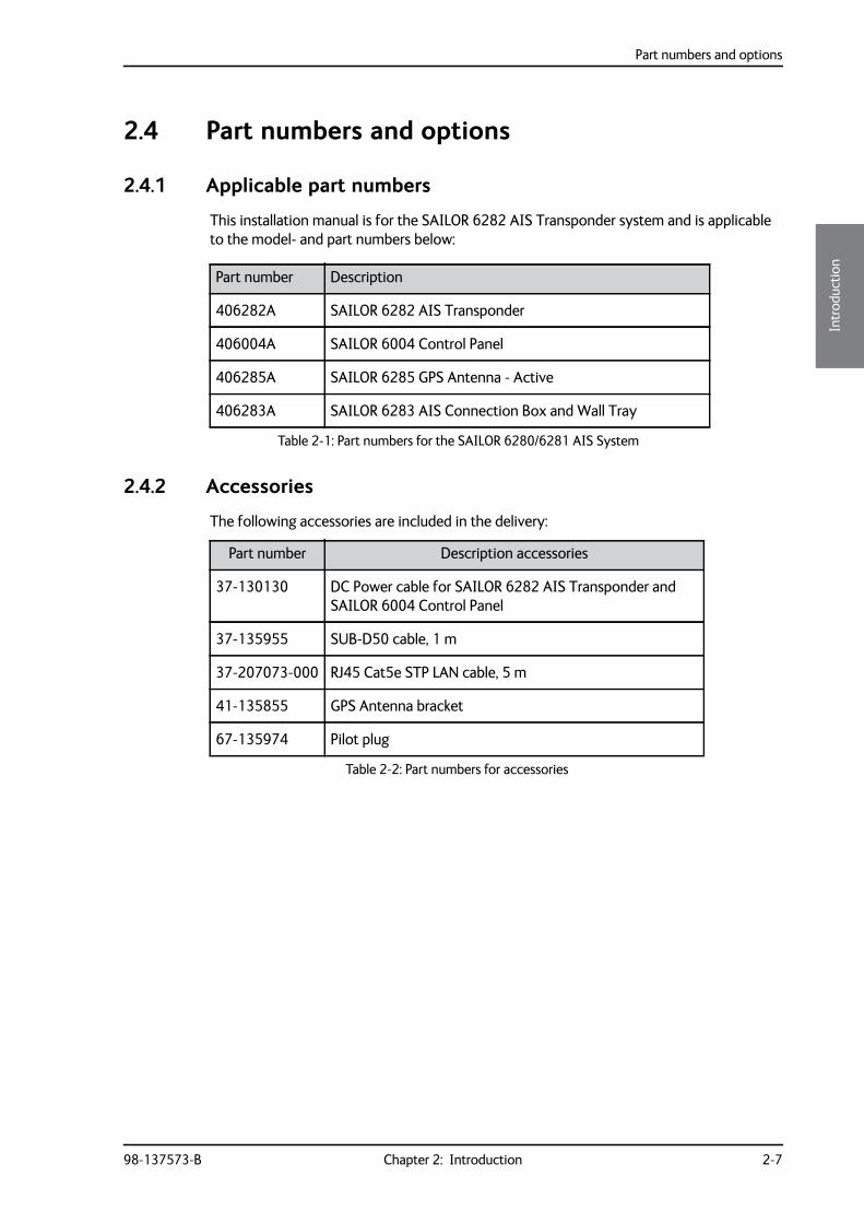
This installation manual is for the SAILOR 6282 AIS Transponder system and is applicable to the model- and part numbers below:
2.4.2 Accessories
The following accessories are included in the delivery:
Part number Description
406282A SAILOR 6282 AIS Transponder
406004A SAILOR 6004 Control Panel
406285A SAILOR 6285 GPS Antenna - Active
406283A SAILOR 6283 AIS Connection Box and Wall Tray
Table 2-1: Part numbers for the SAILOR 6280/6281 AIS System
Part number Description accessories
37-130130 DC Power cable for SAILOR 6282 AIS Transponder and SAILOR 6004 Control Panel
37-135955 SUB-D50 cable, 1 m
37-207073-000 RJ45 Cat5e STP LAN cable, 5 m
41-135855 GPS Antenna bracket
67-135974 Pilot plug
Table 2-2: Part numbers for accessories

Part numbers and options
2-8 Chapter 2: Introduction 98-137573-B
98-137573-B 3-1
Chapter 33333
Inst
alla
tion
Installation 3
This chapter has the following sections:
• Unpacking and initial inspection
• VHF and GPS antenna installation
• Physical installation of the SAILOR 6280 AIS System
• Physical installation of the SAILOR 6281 AIS System
• Physical installation of the SAILOR 6004 Control panel
3.1 Unpacking and initial inspection
3.1.1 Unpacking
The following items are included in the delivery of a SAILOR 6282 AIS Transponder:
• SAILOR 6282 AIS Transponder
• SAILOR 6285 GPS Antenna - Active
• GPS antenna bracket
• User manual SAILOR 6282 AIS Transponder & SAILOR 6280/6281 AIS System
• Installation guide SAILOR 6282 AIS Transponder
• Installation guide SAILOR 6285 GPS Antenna - Active
• Power cable, 1 m
• Cable D-SUB, 50 pin, 1 m
• Cable RJ45 Cat5e STP, 5 m
• Fuse puller
• Fuse (7.5 AF)
• Screw M5-40 TORX, black (5 pieces)
• Screw ST4.8x50 TORX (5 pieces)
• Pilot plug
3.1.2 Initial inspection
Inspect the shipping carton immediately upon receipt for evidence of damage during transport. If the shipping carton is severely damaged or water stained, request that the carrier's agent be present when opening the carton. Save the carton packing material for future use.
VHF and GPS antenna installation
3-2 Chapter 3: Installation 98-137573-B
After unpacking the system, inspect it thoroughly for hidden damage and loose components or fittings. If the contents are incomplete, if there is mechanical damage or defect, or if the system does not work properly, notify your dealer.
3.2 VHF and GPS antenna installationThe SAILOR 6282 AIS Transponder must be installed with one antenna for VHF RX/TX communication and one antenna for GPS communication. You can install all commonly available 50 Ohm antennas covering the appropriate frequency range and providing a VSWR less than 1.5 over this range.
For further details on equipment and antenna installation, see IMOCOMSAR/Circ. 32, GUIDELINES FOR THE HARMONIZATION OF GMDSS REQUIREMENTS FOR RADIO INSTALLATIONS ON BOARD SOLAS SHIPS.
3.2.1 Combined VHF and GPS antenna
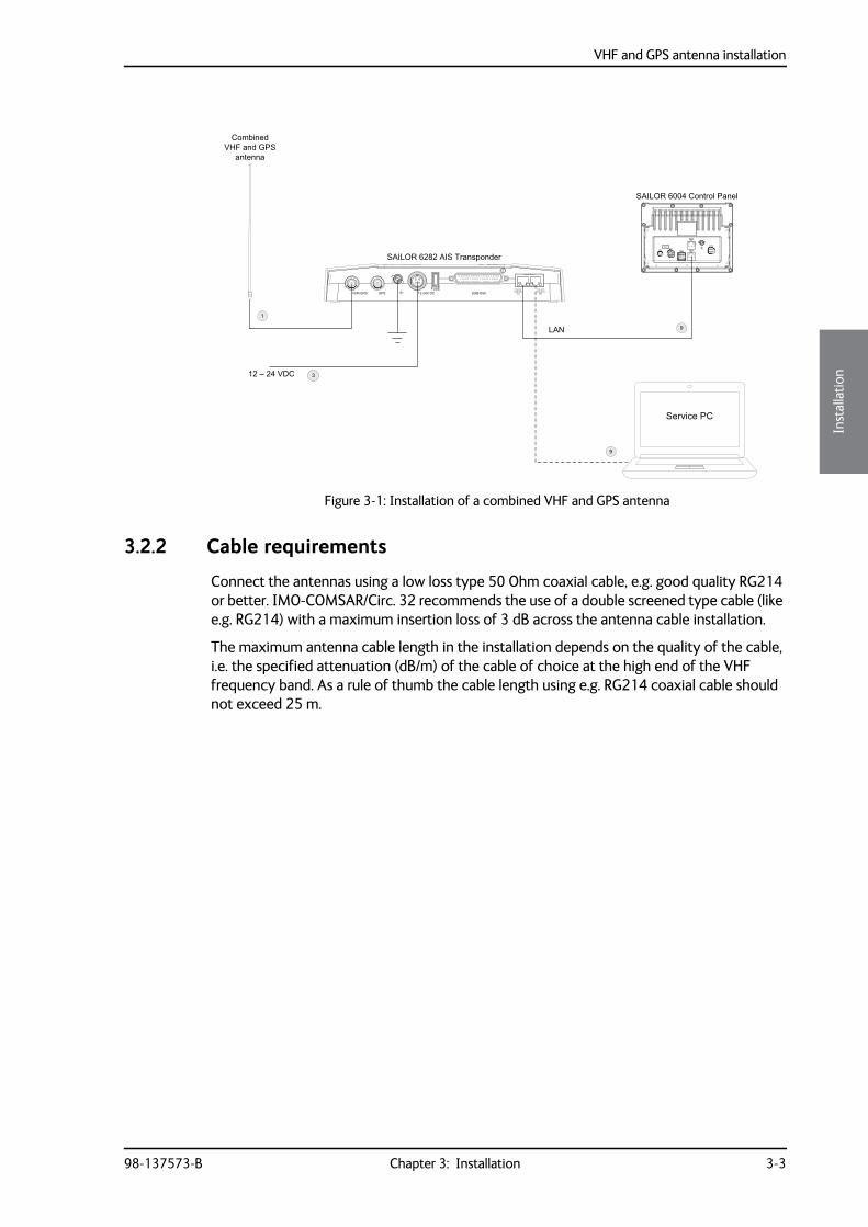
Typically the SAILOR 6282 AIS Transponder is connected to a VHF antenna and a GPS with two cables. The SAILOR 6282 AIS Transponder can also be connected to a combined VHF and GPS antenna with only one cable. The combined antenna must be approved to work with the SAILOR 6282 AIS Transponder. The approved combined VHF and GPS antennas are listed in Table 3-3 on page 3-11.
The combined VHF and GPS antenna is connected to the VHF plug of the SAILOR 6282 AIS Transponder. During installation the SAILOR 6282 AIS Transponder must be set up for the one-cable installation. You do this using a service PC with the TT6282 AIS Service Interface, setup menu.
WARNING! To avoid electric shock, do not apply power to the system if there is any sign of shipping damage to any part of the front or rear panel or the outer cover. Read the safety summary at the front of this manual before installing or operating the system.
VHF and GPS antenna installation
98-137573-B Chapter 3: Installation 3-3
3333
Inst
alla
tion
3.2.2 Cable requirements
Connect the antennas using a low loss type 50 Ohm coaxial cable, e.g. good quality RG214 or better. IMO-COMSAR/Circ. 32 recommends the use of a double screened type cable (like e.g. RG214) with a maximum insertion loss of 3 dB across the antenna cable installation.
The maximum antenna cable length in the installation depends on the quality of the cable, i.e. the specified attenuation (dB/m) of the cable of choice at the high end of the VHF frequency band. As a rule of thumb the cable length using e.g. RG214 coaxial cable should not exceed 25 m.
Figure 3-1: Installation of a combined VHF and GPS antenna
12 – 24 VDC
LAN
1
3
SAILOR 6004 Control Panel
9
SAILOR 6282 AIS Transponder
SUB-D50FUSE
12-24V DCGPSVHF/GPS
9
CombinedVHF and GPS
antenna
Service PC
VHF and GPS antenna installation
3-4 Chapter 3: Installation 98-137573-B
3.2.3 VHF RX/TX antenna
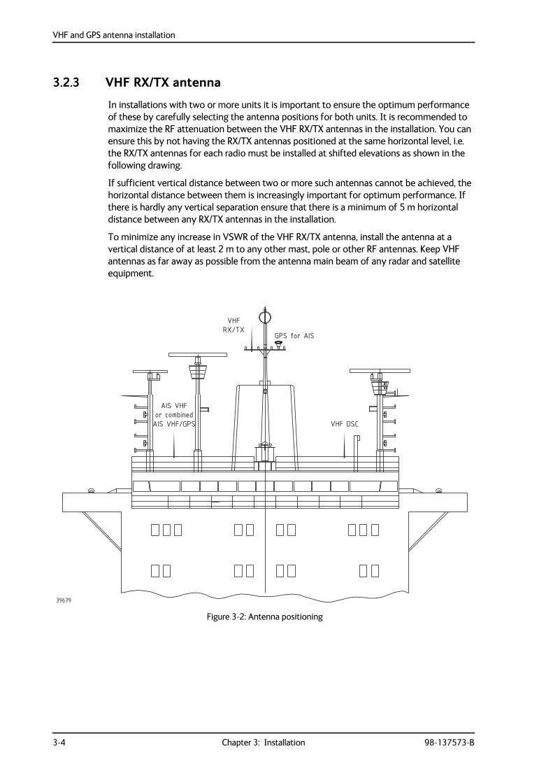
In installations with two or more units it is important to ensure the optimum performance of these by carefully selecting the antenna positions for both units. It is recommended to maximize the RF attenuation between the VHF RX/TX antennas in the installation. You can ensure this by not having the RX/TX antennas positioned at the same horizontal level, i.e. the RX/TX antennas for each radio must be installed at shifted elevations as shown in the following drawing.
If sufficient vertical distance between two or more such antennas cannot be achieved, the horizontal distance between them is increasingly important for optimum performance. If there is hardly any vertical separation ensure that there is a minimum of 5 m horizontal distance between any RX/TX antennas in the installation.
To minimize any increase in VSWR of the VHF RX/TX antenna, install the antenna at a vertical distance of at least 2 m to any other mast, pole or other RF antennas. Keep VHF antennas as far away as possible from the antenna main beam of any radar and satellite equipment.
Figure 3-2: Antenna positioning
RX/TX
or combinedVHF DSC
VHF
GPS for AIS
AIS VHF
AIS VHF/GPS
39679
VHF and GPS antenna installation
98-137573-B Chapter 3: Installation 3-5
3333
Inst
alla
tion
3.2.4 SAILOR 6285 GPS Antenna - Active
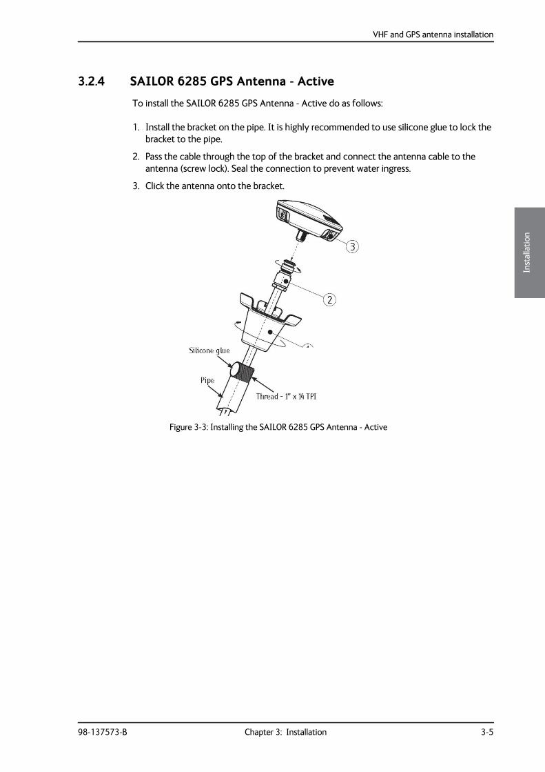
To install the SAILOR 6285 GPS Antenna - Active do as follows:
1. Install the bracket on the pipe. It is highly recommended to use silicone glue to lock the bracket to the pipe.
2. Pass the cable through the top of the bracket and connect the antenna cable to the antenna (screw lock). Seal the connection to prevent water ingress.
3. Click the antenna onto the bracket.
Figure 3-3: Installing the SAILOR 6285 GPS Antenna - Active
Physical installation of the SAILOR 6280 AIS System
3-6 Chapter 3: Installation 98-137573-B
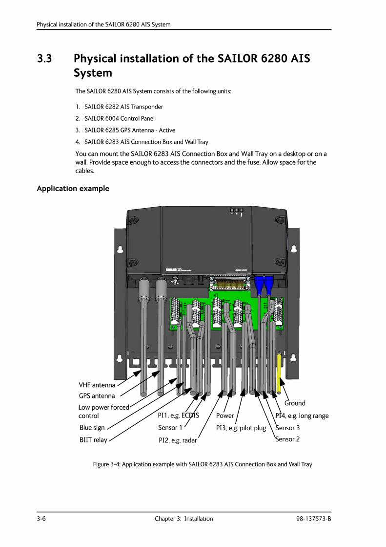
3.3 Physical installation of the SAILOR 6280 AIS SystemThe SAILOR 6280 AIS System consists of the following units:
1. SAILOR 6282 AIS Transponder
2. SAILOR 6004 Control Panel
3. SAILOR 6285 GPS Antenna - Active
4. SAILOR 6283 AIS Connection Box and Wall Tray
You can mount the SAILOR 6283 AIS Connection Box and Wall Tray on a desktop or on a wall. Provide space enough to access the connectors and the fuse. Allow space for the cables.
Application example
Figure 3-4: Application example with SAILOR 6283 AIS Connection Box and Wall Tray
VHF antenna
GPS antenna
Low power forcedcontrol
Blue sign
BIIT relay
Ground
PI1, e.g. ECDIS
Sensor 1
PI2, e.g. radar
Power
PI3, e.g. pilot plug
Sensor 2
Sensor 3
PI4, e.g. long range
Physical installation of the SAILOR 6280 AIS System
98-137573-B Chapter 3: Installation 3-7
3333
Inst
alla
tion
Compass safe distance
Make sure that the SAILOR 6282 AIS Transponder is far enough from any magnetic compass. See the following table for the safe distance after magnetization between the nearest point of the device and the centre of the compass at which it will produce a deviation of 0.3°.
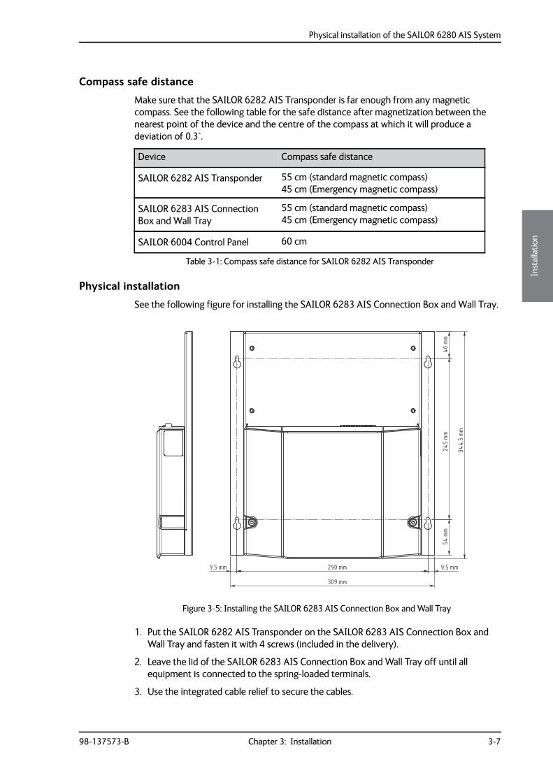
Physical installation
See the following figure for installing the SAILOR 6283 AIS Connection Box and Wall Tray.
1. Put the SAILOR 6282 AIS Transponder on the SAILOR 6283 AIS Connection Box and Wall Tray and fasten it with 4 screws (included in the delivery).
2. Leave the lid of the SAILOR 6283 AIS Connection Box and Wall Tray off until all equipment is connected to the spring-loaded terminals.
3. Use the integrated cable relief to secure the cables.
Device Compass safe distance
SAILOR 6282 AIS Transponder 55 cm (standard magnetic compass)45 cm (Emergency magnetic compass)
SAILOR 6283 AIS Connection Box and Wall Tray
55 cm (standard magnetic compass)45 cm (Emergency magnetic compass)
SAILOR 6004 Control Panel 60 cm
Table 3-1: Compass safe distance for SAILOR 6282 AIS Transponder
Figure 3-5: Installing the SAILOR 6283 AIS Connection Box and Wall Tray
40mm
54mm
245mm
344.5mm
290 mm
309 mm
9.5 mm 9.5 mm
Physical installation of the SAILOR 6280 AIS System
3-8 Chapter 3: Installation 98-137573-B
4. Having connected and secured all cables fasten the lid on the SAILOR 6283 AIS Connection Box and Wall Tray with 2 screws (included in the delivery).
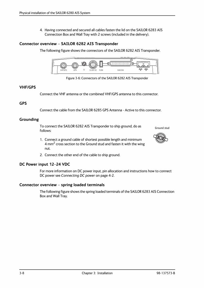
Connector overview – SAILOR 6282 AIS Transponder
The following figure shows the connectors of the SAILOR 6282 AIS Transponder.
VHF/GPS
Connect the VHF antenna or the combined VHF/GPS antenna to this connector.
GPS
Connect the cable from the SAILOR 6285 GPS Antenna - Active to this connector.
Grounding
To connect the SAILOR 6282 AIS Transponder to ship ground, do as follows:
1. Connect a ground cable of shortest possible length and minimum 4 mm2 cross section to the Ground stud and fasten it with the wing nut.
2. Connect the other end of the cable to ship ground.
DC Power input 12–24 VDC
For more information on DC power input, pin allocation and instructions how to connect DC power see Connecting DC power on page 4-2.
Connector overview – spring loaded terminals
The following figure shows the spring loaded terminals of the SAILOR 6283 AIS Connection Box and Wall Tray.
Figure 3-6: Connectors of the SAILOR 6282 AIS Transponder
VHF/GPS GPS 12-24V DC FUSE SUB-D50
1
Ground stud
Physical installation of the SAILOR 6280 AIS System
98-137573-B Chapter 3: Installation 3-9
3333
Inst
alla
tion
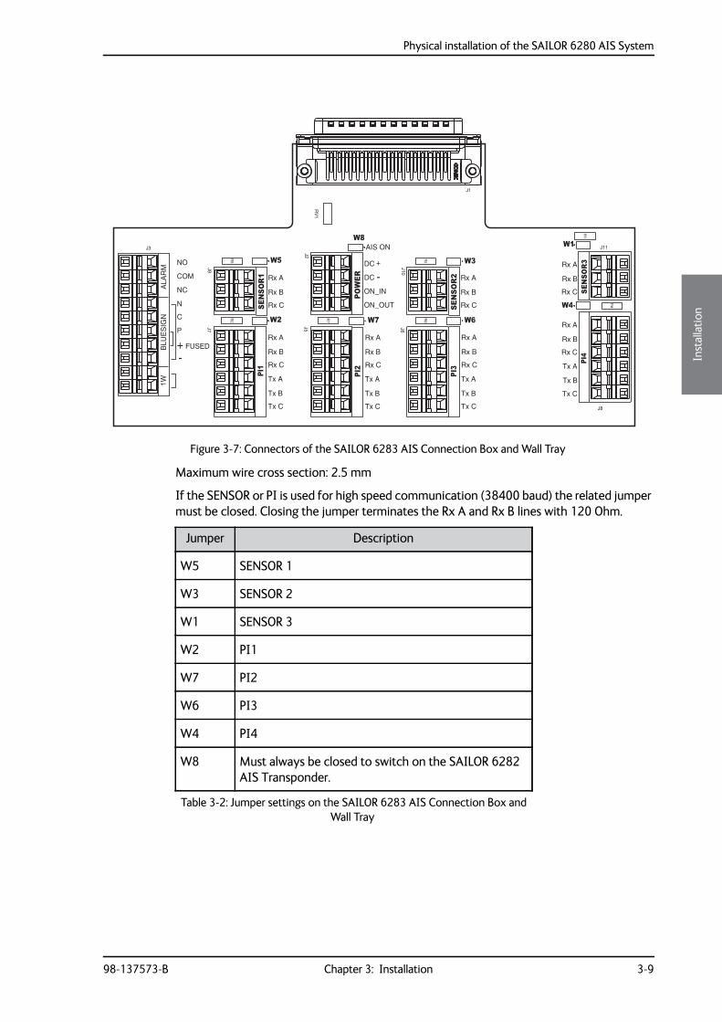
Maximum wire cross section: 2.5 mm
If the SENSOR or PI is used for high speed communication (38400 baud) the related jumper must be closed. Closing the jumper terminates the Rx A and Rx B lines with 120 Ohm.
Figure 3-7: Connectors of the SAILOR 6283 AIS Connection Box and Wall Tray
W8
W7 W6
W5
W4
W3
W2
W1
RV
1
R7
R6
R5
R4
R3
R2
R1
J3
J2
J7
J5 J6
J8
J9 J10
J11
J1
ALA
RM
BLU
ES
IGN
1W
NO
COM
NC
N
P
C
FUSED
-
SENSO
R1PI1
Rx A
Rx B
Rx C
Rx C
Rx B
Rx A
Tx C
Tx B
Tx A
PI2
AIS ON
POWER
DC
DC
ON_IN
ON_OUT SENSO
R2
PI3
Tx C
Tx B
Tx A
Rx C
Rx B
Rx A
Rx C
Rx B
Rx A
SENSO
R3PI4
+
+
-
Rx C
Rx B
Rx A
Tx C
Tx B
Tx A
Rx C
Rx B
Rx A
Tx C
Tx B
Tx A
Rx A
Rx B
Rx C
Jumper Description
W5 SENSOR 1
W3 SENSOR 2
W1 SENSOR 3
W2 PI1
W7 PI2
W6 PI3
W4 PI4
W8 Must always be closed to switch on the SAILOR 6282 AIS Transponder.
Table 3-2: Jumper settings on the SAILOR 6283 AIS Connection Box and Wall Tray
Physical installation of the SAILOR 6280 AIS System
3-10 Chapter 3: Installation 98-137573-B
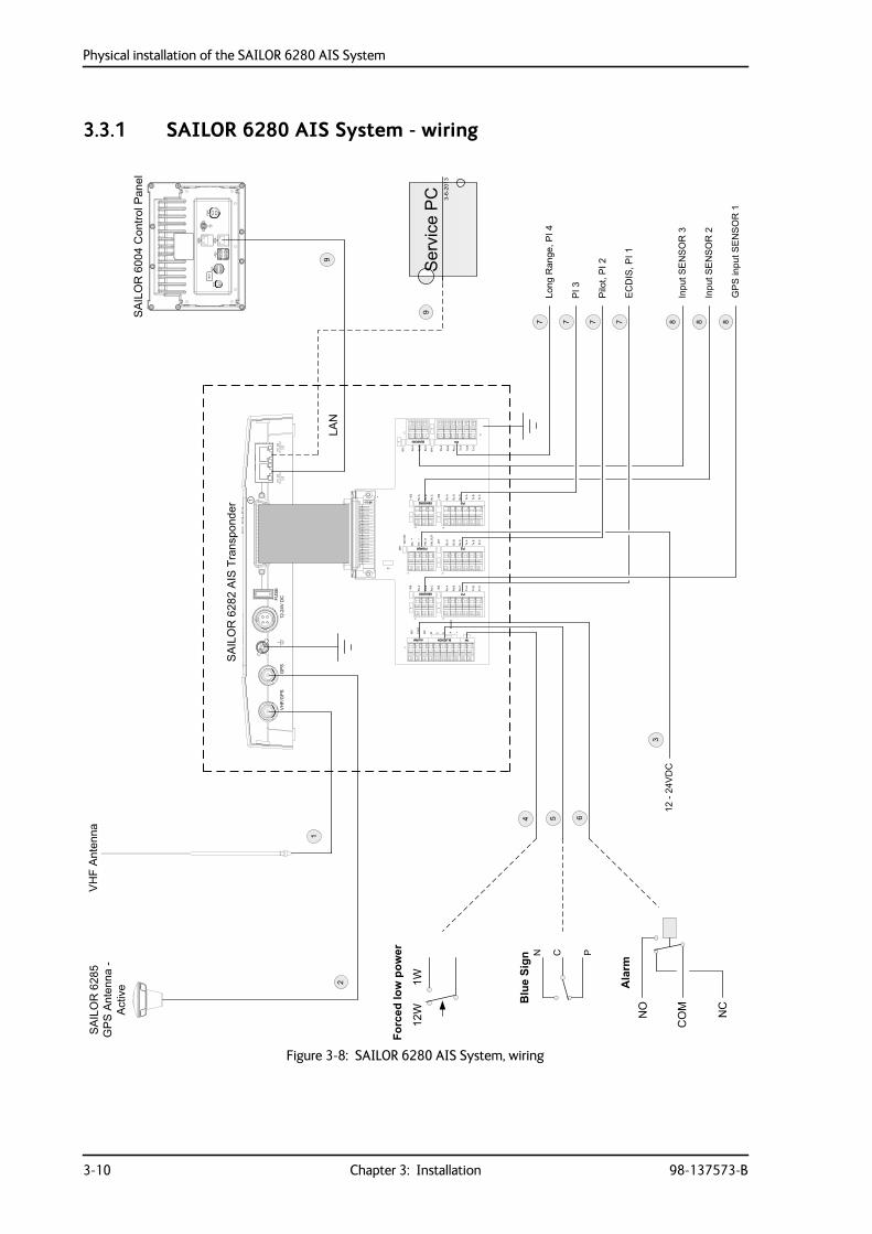
3.3.1 SAILOR 6280 AIS System - wiring
Figure 3-8: SAILOR 6280 AIS System, wiring
12-2
4VD
C
5
3
4 6
7
SA
ILO
R60
04C
ontro
lPan
el
777 8 8 8
9
Long
Ran
ge,P
I4
Pilo
t,P
I2
GP
Sin
putS
EN
SO
R1
EC
DIS
,PI1
Inpu
tSE
NS
OR
3
Inpu
tSE
NS
OR
2
PI3
9
SA
ILO
R62
85G
PS
Ant
enna
-A
ctiv
e
LAN
2
1
SA
ILO
R62
82A
ISTr
ansp
onde
r
SU
B-D
50FU
SE
12-2
4VD
CG
PS
VH
F/G
PS
VH
FA
nten
na
3-6-
2013
Ser
vice
PC
12W
1W
Forcedlowpower
NO
CO
M NC
Alarm
BlueSign
N C P
Physical installation of the SAILOR 6280 AIS System
98-137573-B Chapter 3: Installation 3-11
3333
Inst
alla
tion
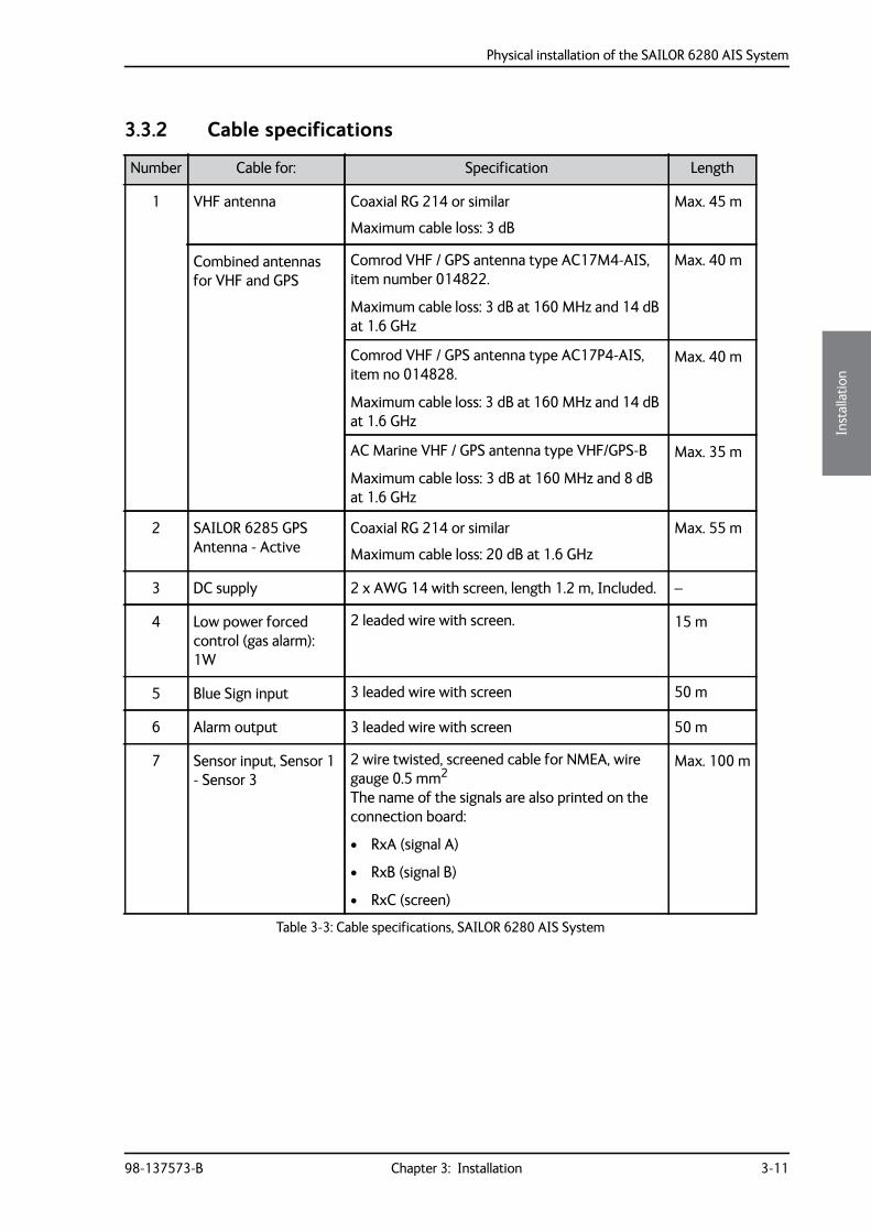
3.3.2 Cable specifications
Number Cable for: Specification Length
1 VHF antenna Coaxial RG 214 or similar
Maximum cable loss: 3 dB
Max. 45 m
Combined antennas for VHF and GPS
Comrod VHF / GPS antenna type AC17M4-AIS, item number 014822.
Maximum cable loss: 3 dB at 160 MHz and 14 dB at 1.6 GHz
Max. 40 m
Comrod VHF / GPS antenna type AC17P4-AIS, item no 014828.
Maximum cable loss: 3 dB at 160 MHz and 14 dB at 1.6 GHz
Max. 40 m
AC Marine VHF / GPS antenna type VHF/GPS-B
Maximum cable loss: 3 dB at 160 MHz and 8 dB at 1.6 GHz
Max. 35 m
2 SAILOR 6285 GPS Antenna - Active
Coaxial RG 214 or similar
Maximum cable loss: 20 dB at 1.6 GHz
Max. 55 m
3 DC supply 2 x AWG 14 with screen, length 1.2 m, Included. –
4 Low power forced control (gas alarm): 1W
2 leaded wire with screen. 15 m
5 Blue Sign input 3 leaded wire with screen 50 m
6 Alarm output 3 leaded wire with screen 50 m
7 Sensor input, Sensor 1 - Sensor 3
2 wire twisted, screened cable for NMEA, wire gauge 0.5 mm2
The name of the signals are also printed on the connection board:
• RxA (signal A)
• RxB (signal B)
• RxC (screen)
Max. 100 m
Table 3-3: Cable specifications, SAILOR 6280 AIS System
Physical installation of the SAILOR 6281 AIS System
3-12 Chapter 3: Installation 98-137573-B
3.4 Physical installation of the SAILOR 6281 AIS SystemThe SAILOR 6281 AIS System consists of the following units:
1. SAILOR 6282 AIS Transponder
2. SAILOR 6004 Control Panel
3. SAILOR 6285 GPS Antenna - Active
You can mount the SAILOR 6282 AIS Transponder on a desktop or on a wall. Provide space enough to access the connectors and the fuse. Allow space for the cables.
Compass safe distance
See Compass safe distance on page 3-7.
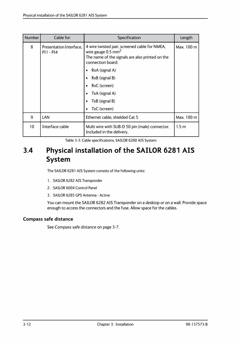
8 Presentation Interface, PI1 - PI4
4 wire twisted pair, screened cable for NMEA, wire gauge 0.5 mm2
The name of the signals are also printed on the connection board:
• RxA (signal A)
• RxB (signal B)
• RxC (screen)
• TxA (signal A)
• TxB (signal B)
• TxC (screen)
Max. 100 m
9 LAN Ethernet cable, shielded Cat 5 Max. 100 m
10 Interface cable Multi wire with SUB-D 50 pin (male) connector. Included in the delivery.
1.5 m
Number Cable for: Specification Length
Table 3-3: Cable specifications, SAILOR 6280 AIS System
Physical installation of the SAILOR 6281 AIS System
98-137573-B Chapter 3: Installation 3-13
3333
Inst
alla
tion
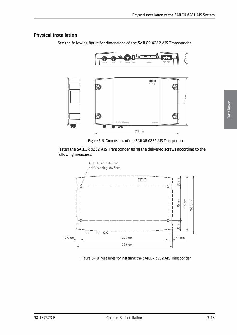
Physical installation
See the following figure for dimensions of the SAILOR 6282 AIS Transponder.
Fasten the SAILOR 6282 AIS Transponder using the delivered screws according to the following measures:
Figure 3-9: Dimensions of the SAILOR 6282 AIS Transponder
Figure 3-10: Measures for installing the SAILOR 6282 AIS Transponder
270 mm
155mm
42.5
mm155mm
270 mm
95mm
30mm
30mm
245 mm12.5 mm 12.5 mm
162.5mm
4 x M5 or hole forself-tapping ø4.8mm
Physical installation of the SAILOR 6281 AIS System
3-14 Chapter 3: Installation 98-137573-B
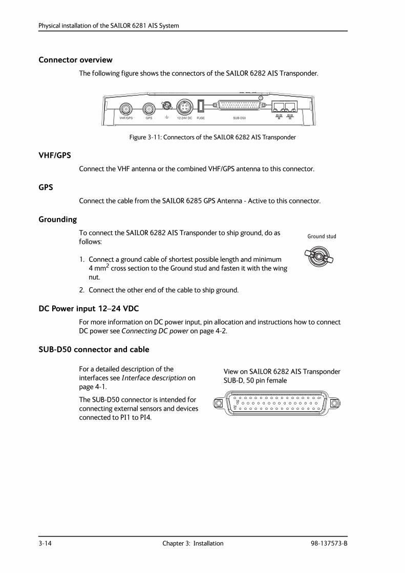
Connector overview
The following figure shows the connectors of the SAILOR 6282 AIS Transponder.
VHF/GPS
Connect the VHF antenna or the combined VHF/GPS antenna to this connector.
GPS
Connect the cable from the SAILOR 6285 GPS Antenna - Active to this connector.
Grounding
To connect the SAILOR 6282 AIS Transponder to ship ground, do as follows:
1. Connect a ground cable of shortest possible length and minimum 4 mm2 cross section to the Ground stud and fasten it with the wing nut.
2. Connect the other end of the cable to ship ground.
DC Power input 12–24 VDC
For more information on DC power input, pin allocation and instructions how to connect DC power see Connecting DC power on page 4-2.
SUB-D50 connector and cable
For a detailed description of the interfaces see Interface description on page 4-1.
The SUB-D50 connector is intended for connecting external sensors and devices connected to PI1 to PI4.
Figure 3-11: Connectors of the SAILOR 6282 AIS Transponder
VHF/GPS GPS 12-24V DC FUSE SUB-D50
1
Ground stud
118
34
View on SAILOR 6282 AIS TransponderSUB-D, 50 pin female
Physical installation of the SAILOR 6281 AIS System
98-137573-B Chapter 3: Installation 3-15
3333
Inst
alla
tion
LAN connector and cable
The SAILOR 6282 AIS Transponder has two LAN connections used for connection to the display and keyboard of the SAILOR 6004 Control Panel and for ThraneLINK Management Application (Service Tool).
The two connectors are identical and of the type RJ45 with 8 leads
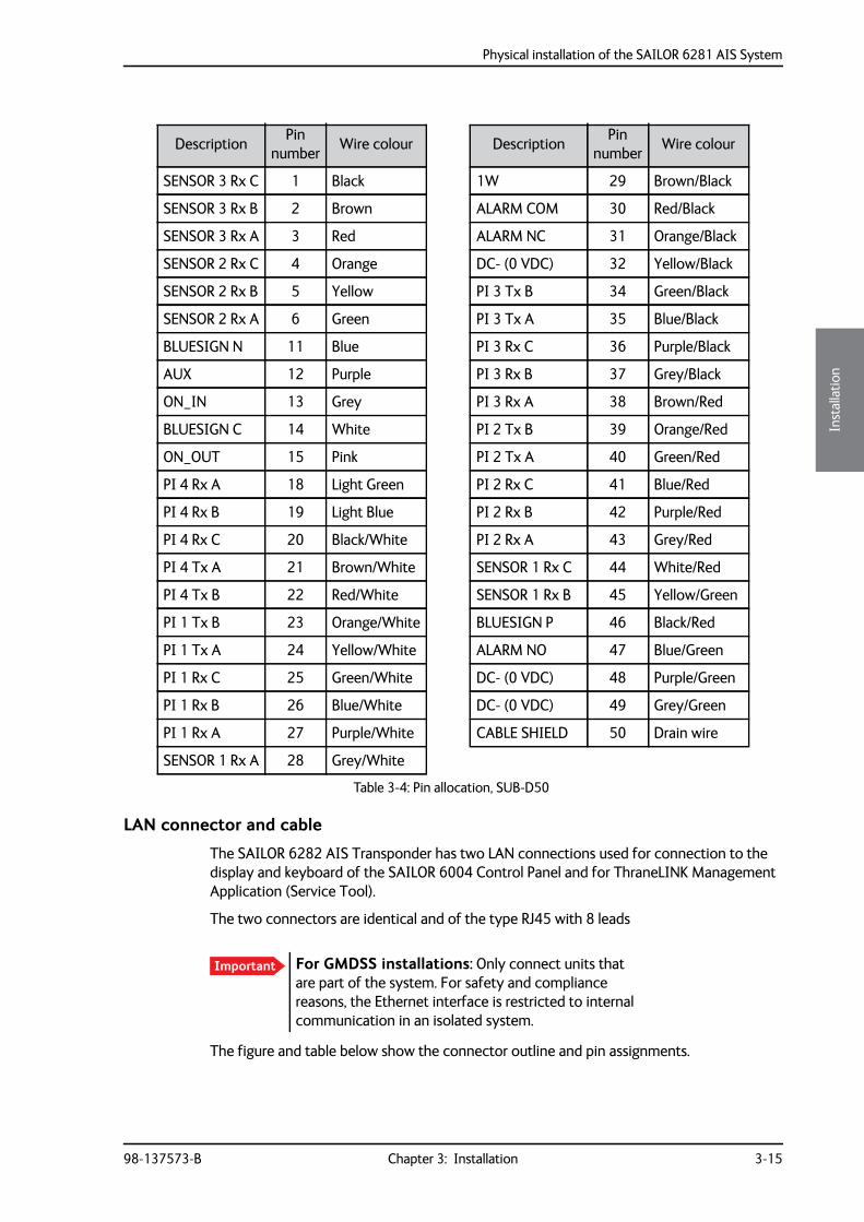
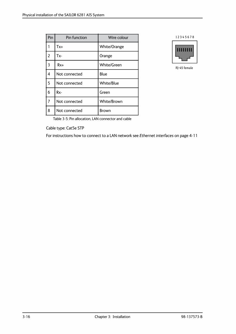
The figure and table below show the connector outline and pin assignments.
Description Pinnumber Wire colour Description Pin
number Wire colour
SENSOR 3 Rx C 1 Black 1W 29 Brown/Black
SENSOR 3 Rx B 2 Brown ALARM COM 30 Red/Black
SENSOR 3 Rx A 3 Red ALARM NC 31 Orange/Black
SENSOR 2 Rx C 4 Orange DC- (0 VDC) 32 Yellow/Black
SENSOR 2 Rx B 5 Yellow PI 3 Tx B 34 Green/Black
SENSOR 2 Rx A 6 Green PI 3 Tx A 35 Blue/Black
BLUESIGN N 11 Blue PI 3 Rx C 36 Purple/Black
AUX 12 Purple PI 3 Rx B 37 Grey/Black
ON_IN 13 Grey PI 3 Rx A 38 Brown/Red
BLUESIGN C 14 White PI 2 Tx B 39 Orange/Red
ON_OUT 15 Pink PI 2 Tx A 40 Green/Red
PI 4 Rx A 18 Light Green PI 2 Rx C 41 Blue/Red
PI 4 Rx B 19 Light Blue PI 2 Rx B 42 Purple/Red
PI 4 Rx C 20 Black/White PI 2 Rx A 43 Grey/Red
PI 4 Tx A 21 Brown/White SENSOR 1 Rx C 44 White/Red
PI 4 Tx B 22 Red/White SENSOR 1 Rx B 45 Yellow/Green
PI 1 Tx B 23 Orange/White BLUESIGN P 46 Black/Red
PI 1 Tx A 24 Yellow/White ALARM NO 47 Blue/Green
PI 1 Rx C 25 Green/White DC- (0 VDC) 48 Purple/Green
PI 1 Rx B 26 Blue/White DC- (0 VDC) 49 Grey/Green
PI 1 Rx A 27 Purple/White CABLE SHIELD 50 Drain wire
SENSOR 1 Rx A 28 Grey/White
Table 3-4: Pin allocation, SUB-D50
Important For GMDSS installations: Only connect units that are part of the system. For safety and compliance reasons, the Ethernet interface is restricted to internal communication in an isolated system.
Physical installation of the SAILOR 6281 AIS System
3-16 Chapter 3: Installation 98-137573-B
Cable type: Cat5e STP
For instructions how to connect to a LAN network see Ethernet interfaces on page 4-11
Pin Pin function Wire colour
1 Tx+ White/Orange
2 Tx- Orange
3 Rx+ White/Green
4 Not connected Blue
5 Not connected White/Blue
6 Rx- Green
7 Not connected White/Brown
8 Not connected Brown
Table 3-5: Pin allocation, LAN connector and cable
RJ-45 female
1 2 3 4 5 6 7 8
Physical installation of the SAILOR 6281 AIS System
98-137573-B Chapter 3: Installation 3-17
3333
Inst
alla
tion
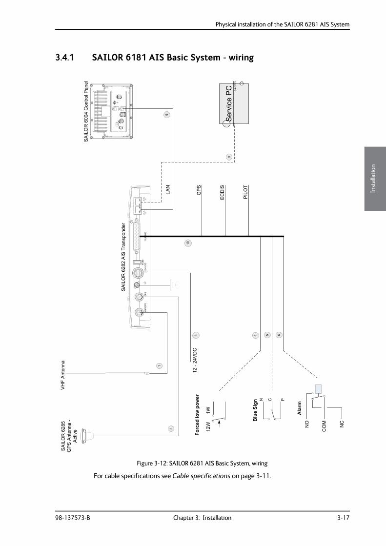
3.4.1 SAILOR 6181 AIS Basic System - wiring
For cable specifications see Cable specifications on page 3-11.
Figure 3-12: SAILOR 6281 AIS Basic System, wiring
SAIL
OR
6285
GPS
Ante
nna
-Ac
tive
12-2
4VD
C
LAN
2
5
1
3 4 6
SAIL
OR
6004
Con
trolP
anel
10
9
GPS
ECD
IS
PILO
T
12W
1W
Forcedlowpower
NO
CO
M NC
Alarm
BlueSign
N C P
SAIL
OR
6282
AIS
Tran
spon
der
SUB-
D50
FUSE
12-2
4VD
CG
PSVH
F/G
PS
3-6-
2013
Serv
ice
PC9
VHF
Ante
nna
Physical installation of the SAILOR 6004 Control panel
3-18 Chapter 3: Installation 98-137573-B
3.5 Physical installation of the SAILOR 6004 Control panelFor instructions how to install the SAILOR 6004 Control Panel see separate installation manual for the SAILOR 6004 Control panel (part number 98-136644).
Connect a LAN connector at the SAILOR 6282 AIS Transponder to a LAN connector at the SAILOR 6004 Control Panel.
98-137573-B 4-1
Chapter 44444
Inte
rfac
e de
scrip
tion
Interface description 4
This chapter describes the electrical interfaces of the SAILOR 6282 AIS Transponder in details. It has the following sections:
• Power
• Sensor input
• Presentation Interfaces
• Alarm relay
• Low power forced control 1 W
• Blue sign input
• Ethernet interfaces
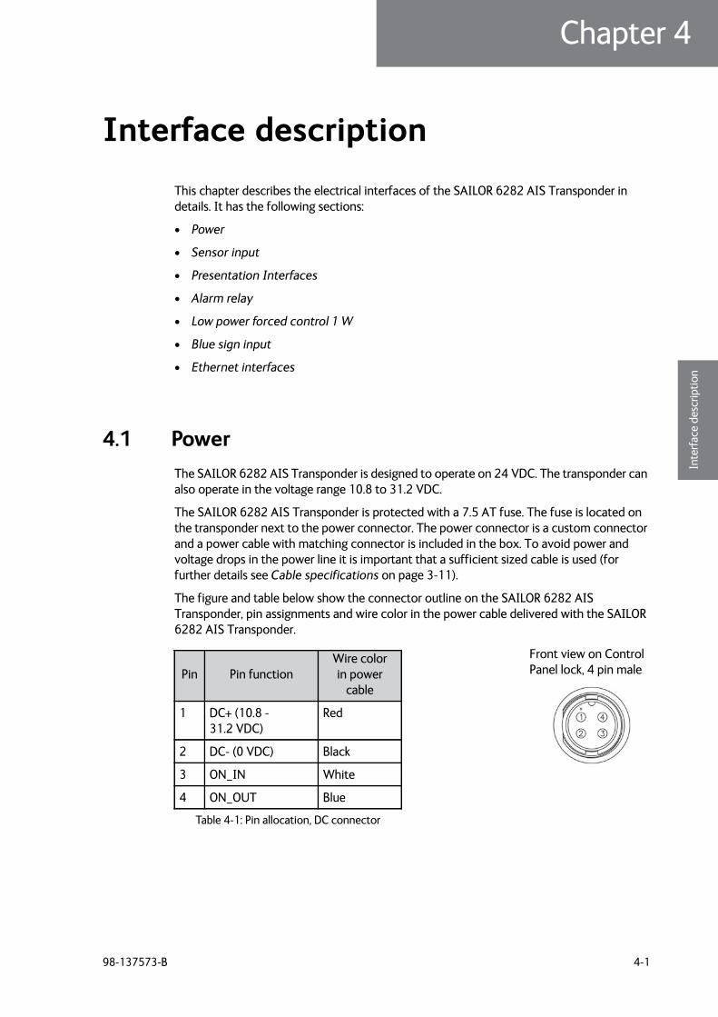
4.1 PowerThe SAILOR 6282 AIS Transponder is designed to operate on 24 VDC. The transponder can also operate in the voltage range 10.8 to 31.2 VDC.
The SAILOR 6282 AIS Transponder is protected with a 7.5 AT fuse. The fuse is located on the transponder next to the power connector. The power connector is a custom connector and a power cable with matching connector is included in the box. To avoid power and voltage drops in the power line it is important that a sufficient sized cable is used (for further details see Cable specifications on page 3-11).
The figure and table below show the connector outline on the SAILOR 6282 AIS Transponder, pin assignments and wire color in the power cable delivered with the SAILOR 6282 AIS Transponder.
Pin Pin functionWire color in power
cable
1 DC+ (10.8 - 31.2 VDC)
Red
2 DC- (0 VDC) Black
3 ON_IN White
4 ON_OUT Blue
Table 4-1: Pin allocation, DC connector
Front view on Control Panel lock, 4 pin male
Power
4-2 Chapter 4: Interface description 98-137573-B
4.1.1 Connecting DC power
Connect DC+ (red wire) to DC out + from your DC supply.
Connect DC- (black wire) to DC out - from your DC supply.
Connect the white wire in the power cable to DC- (black wire) unless you want to use the Remote on/off (ON_IN) function. See the next section for further details on remote on/off.
Connecting remote on/off (ON_IN)
With the remote on/off function you can remotely switch on and off the SAILOR 6282 AIS Transponder. To connect the remote on/off function do as follows:
1. Connect DC+ and DC- as described in the previous section.
2. Connect a switch to the white wire in the power cable (pin3, ON_IN, in the power connector)
3. Connect the other side of the switch to the black wire in the power cable (DC- (0 VDC) in the power connector).
To switch on the SAILOR 6282 AIS Transponder, close the switch.
Connecting on/off control (ON_OUT)
You can use pin 4 in the power connector (blue wire) to switch other units on and off when the SAILOR 6282 AIS Transponder is switched on and off. How to connect this pin depends on the units you connect.
The function of pin 4 is as follows:
• SAILOR 6282 AIS Transponder off: Pin 4 is in high impedance state.
• SAILOR 6282 AIS Transponder on: Pin 4 is low (DC- from the power supply, with 10 kOhm serial resistance).
Sensor input
98-137573-B Chapter 4: Interface description 4-3
4444
Inte
rfac
e de
scrip
tion
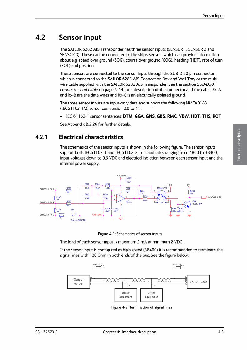
4.2 Sensor inputThe SAILOR 6282 AIS Transponder has three sensor inputs (SENSOR 1, SENSOR 2 and SENSOR 3). These can be connected to the ship’s sensors which can provide information about e.g. speed over ground (SOG), course over ground (COG), heading (HDT), rate of turn (ROT) and position.
These sensors are connected to the sensor input through the SUB-D 50 pin connector, which is connected to the SAILOR 6283 AIS Connection Box and Wall Tray or the multi-wire cable supplied with the SAILOR 6282 AIS Transponder. See the section SUB-D50 connector and cable on page 3-14 for a description of the connector and the cable. Rx-A and Rx-B are the data wires and Rx-C is an electrically isolated ground.
The three sensor inputs are input-only data and support the following NMEA0183 (IEC61162-1/2) sentences, version 2.0 to 4.1:
• IEC 61162-1 sensor sentences: DTM, GGA, GNS, GBS, RMC, VBW, HDT, THS, ROT
See Appendix B.2.26 for further details.
4.2.1 Electrical characteristics
The schematics of the sensor inputs is shown in the following figure. The sensor inputs support both IEC61162-1 and IEC61162-2, i.e. baud rates ranging from 4800 to 38400, input voltages down to 0.3 VDC and electrical isolation between each sensor input and the internal power supply.
The load of each sensor input is maximum 2 mA at minimum 2 VDC.
If the sensor input is configured as high speed (38400) it is recommended to terminate the signal lines with 120 Ohm in both ends of the bus. See the figure below:
Figure 4-1: Schematics of sensor inputs
SENSOR 1 RX B
SENSOR 1 RX A
SENSOR 1 RX C GND_ISO4
SENSOR_1_RX
3V3 3V3
VCC_ISO4
R7791M
-
+ VCC
U38TS7221
2
1
5
4
3
R291100k
R286
1.54k
Q14BC817-40W1
3
2
C623
100nF
BLM15AG102SN1
E27
R293
1k
R285
1.54kR289
464RU39
MOC207-M
1
275
3
6
4 8
R28710k
R290
10k
R28810k
R283
10k
R282
1M
C22022pF
R28410k
R279
1.54k
R786
15.4R
R280
1.54k
R2923.83k
C21922pF
Figure 4-2: Termination of signal lines
equipmentOther
equipmentOther
outputSensor
SAILOR 6282ABC
ABC
120 Ohm 120 Ohm
Sensor input
4-4 Chapter 4: Interface description 98-137573-B
4.2.2 Sensor configuration
All three sensor inputs are IEC61162-1/2 (RS-422) compliant and can be configured individually with different baud rates. From the factory the ports are set up with the default baud rate as stated in the following table:
In the Service Interface you can set the sensor input to another baud rate.
See Interface settings on page 5-14 to learn how to set up the SAILOR 6282 AIS Transponder using the Service Interface.
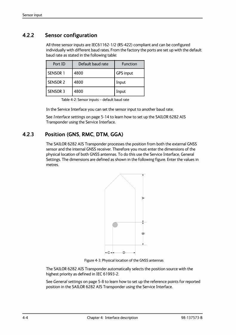
4.2.3 Position (GNS, RMC, DTM, GGA)
The SAILOR 6282 AIS Transponder processes the position from both the external GNSS sensor and the internal GNSS receiver. Therefore you must enter the dimensions of the physical location of both GNSS antennas. To do this use the Service Interface, General Settings. The dimensions are defined as shown in the following figure. Enter the values in metres.
The SAILOR 6282 AIS Transponder automatically selects the position source with the highest priority as defined in IEC 61993-2.
See General settings on page 5-8 to learn how to set up the reference points for reported position in the SAILOR 6282 AIS Transponder using the Service Interface.
Port ID Default baud rate Function
SENSOR 1 4800 GPS input
SENSOR 2 4800 Input
SENSOR 3 4800 Input
Table 4-2: Sensor inputs – default baud rate
Figure 4-3: Physical location of the GNSS antennas
Sensor input
98-137573-B Chapter 4: Interface description 4-5
4444
Inte
rfac
e de
scrip
tion
4.2.4 Heading (HDT)
The SAILOR 6282 AIS Transponder can process heading information from heading sensors that provide an IEC 61162 output. If THS (True Heading and Status) and HDT are available, THS is preferred.
4.2.5 Rate of Turn (ROT)
If a Rate of Turn (ROT) sensor is available and provides an IEC 61162 output, the sensor must be connected to the SAILOR 6282 AIS Transponder.
If the ROT information is not available from a Rate of Turn sensor it may optionally be delivered from another source, e.g. a gyrocompass or other external sources giving ROT or heading.
The SAILOR 6282 AIS Transponder automatically selects the ROT source with the highest priority. The priority is defined in IEC 61993-2. It is decided by the Talker ID, where TI (Turn Indicator) has a higher priority than HE (Heading sensor; lower priority). TI and HE are the talker IDs of these devices.
4.2.6 Log (VBW)
The Log (VBW, Dual ground/water speed) refers to the speed log sensor. It has nothing to do with the malfunction log and system log. The Log (VBW) is about water-referenced and ground-referenced speed data.
Priority: Only one sensor is allowed to be connected to the SAILOR 6282 AIS Transponder. You can also use Talker ID filtering to ensure that VBW only at one port can enter the SAILOR 6282 AIS Transponder.
Presentation Interfaces
4-6 Chapter 4: Interface description 98-137573-B
4.3 Presentation Interfaces
4.3.1 Overview
The SAILOR 6282 AIS Transponder has four presentation interfaces (PI1, PI2, PI3 and PI4). A presentation interface is a bidirectional interface used for e.g. an ECDIS, pilot plug, Long Range equipment or similar. The presentation interfaces are connected through the SUB-D 50 pin connector, which is connected to the SAILOR 6283 AIS Connection Box and Wall Tray or the multi-wire cable supplied with the SAILOR 6282 AIS Transponder. See the section SUB-D50 connector and cable on page 3-14 for a description of the connector and the cable.
Rx-A and Rx-B are the data input wires and Tx-A and Tx-B are the data output wires to the SAILOR 6282 AIS Transponder. Rx-C is an electrically isolated ground for the input. Tx-C is connected to DC- on the SAILOR 6283 AIS Connection Box and Wall Tray.
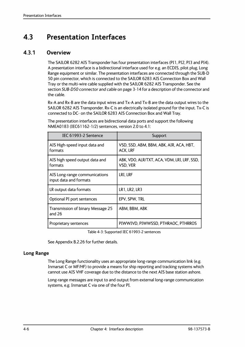
The presentation interfaces are bidirectional data ports and support the following NMEA0183 (IEC61162-1/2) sentences, version 2.0 to 4.1:
See Appendix B.2.26 for further details.
Long Range
The Long Range functionality uses an appropriate long-range communication link (e.g. Inmarsat C or MF/HF) to provide a means for ship reporting and tracking systems which cannot use AIS VHF coverage due to the distance to the next AIS base station ashore.
Long-range messages are input to and output from external long-range communication systems, e.g. Inmarsat C via one of the four PI.
IEC 61993-2 Sentence Support
AIS High-speed input data and formats
VSD, SSD, ABM, BBM, ABK, AIR, ACA, HBT, ACK, LRF
AIS high speed output data and formats
ABK, VDO, ALR/TXT, ACA, VDM, LRI, LRF, SSD, VSD, VER
AIS Long-range communications input data and formats
LRI, LRF
LR output data formats LR1, LR2, LR3
Optional PI port sentences EPV, SPW, TRL
Transmission of binary Message 25 and 26
ABM, BBM, ABK
Proprietary sentences PIWWIVD, PIWWSSD, PTHRAOC, PTHRROS
Table 4-3: Supported IEC 61993-2 sentences
Presentation Interfaces
98-137573-B Chapter 4: Interface description 4-7
4444
Inte
rfac
e de
scrip
tion
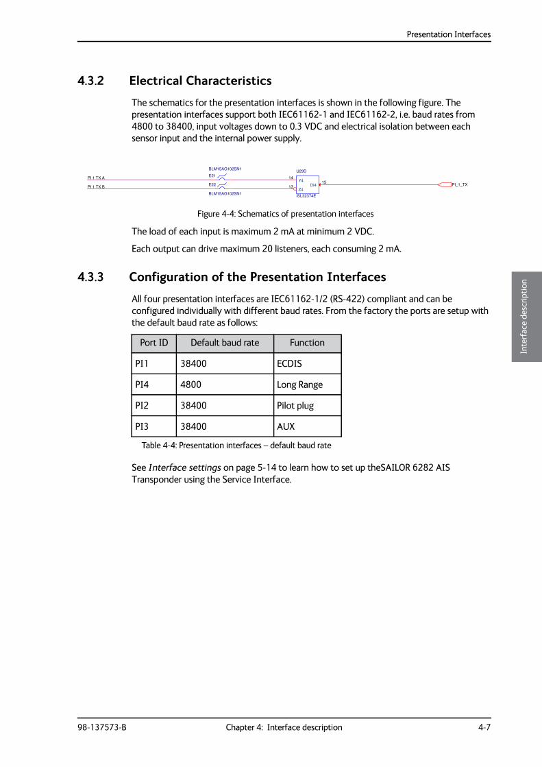
4.3.2 Electrical Characteristics
The schematics for the presentation interfaces is shown in the following figure. The presentation interfaces support both IEC61162-1 and IEC61162-2, i.e. baud rates from 4800 to 38400, input voltages down to 0.3 VDC and electrical isolation between each sensor input and the internal power supply.
The load of each input is maximum 2 mA at minimum 2 VDC.
Each output can drive maximum 20 listeners, each consuming 2 mA.
4.3.3 Configuration of the Presentation Interfaces
All four presentation interfaces are IEC61162-1/2 (RS-422) compliant and can be configured individually with different baud rates. From the factory the ports are setup with the default baud rate as follows:
See Interface settings on page 5-14 to learn how to set up theSAILOR 6282 AIS Transponder using the Service Interface.
Figure 4-4: Schematics of presentation interfaces
PI 1 TX B
PI 1 TX A
PI_1_TX
U29D
ISL32374E
Y414
Z413 DI4
15
BLM15AG102SN1
E21
BLM15AG102SN1
E22
Port ID Default baud rate Function
PI1 38400 ECDIS
PI4 4800 Long Range
PI2 38400 Pilot plug
PI3 38400 AUX
Table 4-4: Presentation interfaces – default baud rate
Presentation Interfaces
4-8 Chapter 4: Interface description 98-137573-B
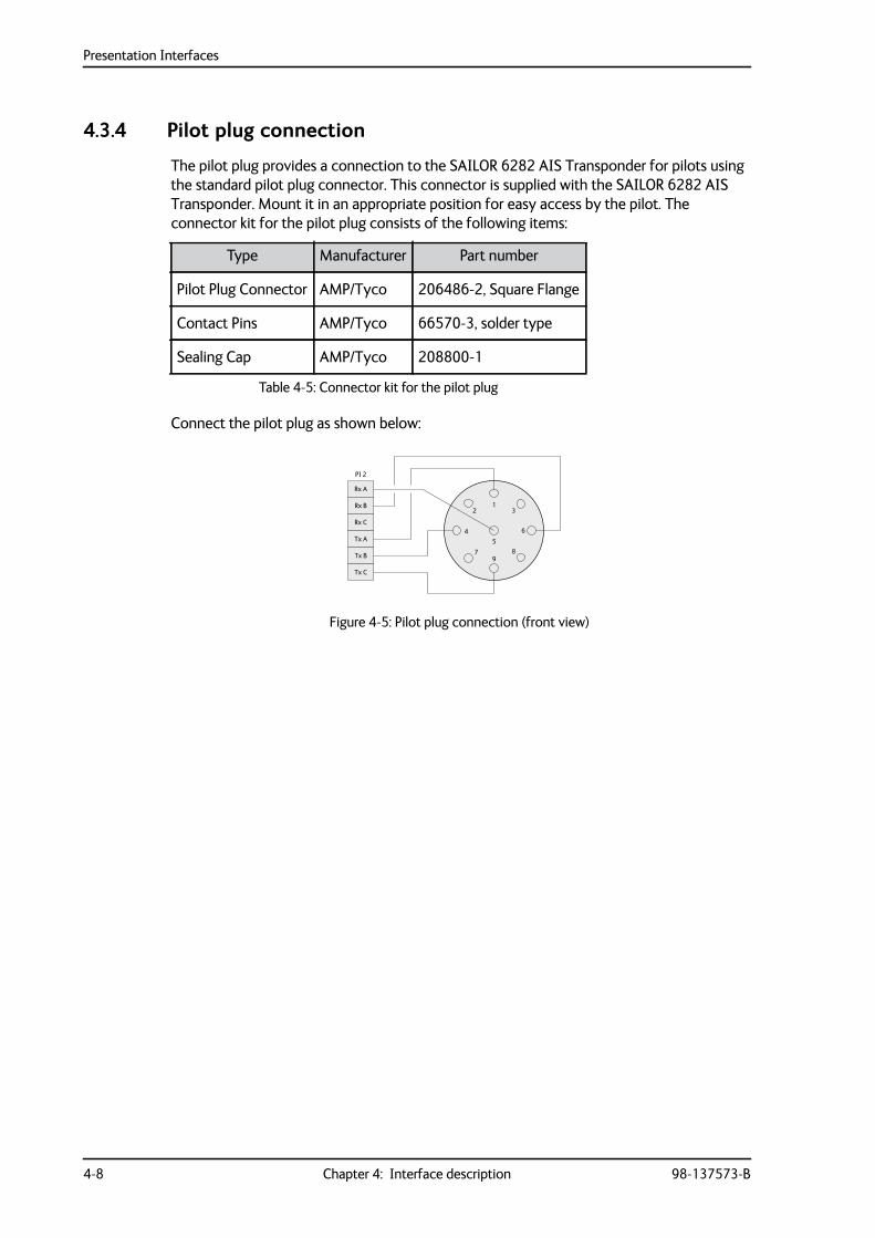
4.3.4 Pilot plug connection
The pilot plug provides a connection to the SAILOR 6282 AIS Transponder for pilots using the standard pilot plug connector. This connector is supplied with the SAILOR 6282 AIS Transponder. Mount it in an appropriate position for easy access by the pilot. The connector kit for the pilot plug consists of the following items:
Connect the pilot plug as shown below:
Type Manufacturer Part number
Pilot Plug Connector AMP/Tyco 206486-2, Square Flange
Contact Pins AMP/Tyco 66570-3, solder type
Sealing Cap AMP/Tyco 208800-1
Table 4-5: Connector kit for the pilot plug
Figure 4-5: Pilot plug connection (front view)
1
5
2 3
4 6
79
8
Rx A
PI 2
Rx B
Rx C
Tx A
Tx B
Tx C
Alarm relay
98-137573-B Chapter 4: Interface description 4-9
4444
Inte
rfac
e de
scrip
tion
4.4 Alarm relayThe SAILOR 6282 AIS Transponder has an internal alarm relay. Connect the alarm relay to an audible alarm device or the ships alarm system, if available.
The ship’s alarm system is connected to the alarm relay through the SUB-D 50 pin connector, which is connected to the SAILOR 6283 AIS Connection Box and Wall Tray or the multi-wire cable included. See the section SUB-D50 connector and cable on page 3-14 for a description of the connector and the cable. The alarm relay connections are described in the table below.
When the SAILOR 6282 AIS Transponder is powered on and there are no alarms the relay is energized, i.e. ALARM COM and ALARM NO is connected.
The maximum switching current is 1 A.
The maximum switching voltage is 125 VAC, 60 VDC.
4.5 Low power forced control 1 WThe transmitter output power of the SAILOR 6282 AIS Transponder is normally 12 W. For the vessel type defined as Tanker(s) and the voyage data set to Moored the transmitter output power will automatically be reduced to 1 W.
The transmitter can be forced to an output power of 1 W under certain conditions, if connected e.g. to a gas alarm. This is done by shorting the '1W' signal to DC-.
The Low power forced control 1W can be connected to a switch to DC- through the SUB-D 50 pin connector, which is connected to the SAILOR 6283 AIS Connection Box and Wall Tray or the multi-wire cable supplied with the SAILOR 6282 AIS Transponder. See the section SUB-D50 connector and cable on page 3-14 for a description of the connector and the cable.
Signal Function
ALARM COM Alarm relay common
ALARM NC Alarm relay normally closed
ALARM NO Alarm relay normally open
Table 4-6: Alarm relay connections
Blue sign input
4-10 Chapter 4: Interface description 98-137573-B
4.6 Blue sign inputBlue sign is used on vessels that are subject to the Inland Waterway specifications where the Blue sign is used as a special manoeuvre indicator. The SAILOR 6282 AIS Transponder supports a direct connection to the Blue sign switch and is able to detect three logical states:
• Set
• Not Set
• Not Connected
The state Not Connected can be used to detect a broken wire.
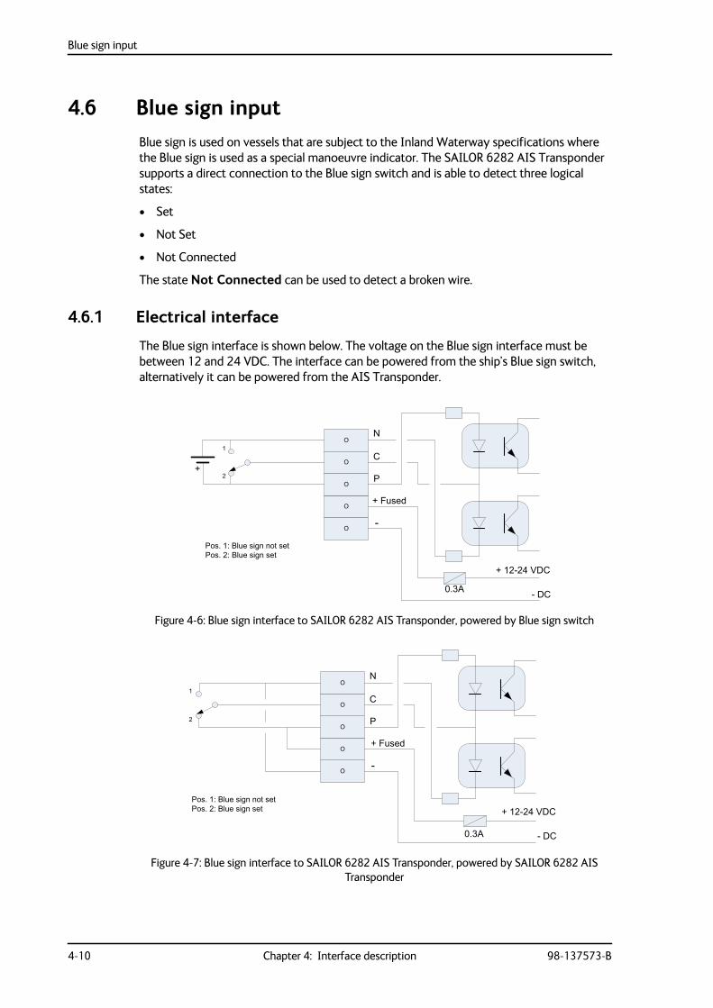
4.6.1 Electrical interface
The Blue sign interface is shown below. The voltage on the Blue sign interface must be between 12 and 24 VDC. The interface can be powered from the ship’s Blue sign switch, alternatively it can be powered from the AIS Transponder.
Figure 4-6: Blue sign interface to SAILOR 6282 AIS Transponder, powered by Blue sign switch
Figure 4-7: Blue sign interface to SAILOR 6282 AIS Transponder, powered by SAILOR 6282 AIS Transponder
O
O
O
O
O
N
C
P
+ Fused
-
- DC
+ 12-24 VDC
0.3A
+2
1
Pos. 1: Blue sign not set Pos. 2: Blue sign set
O
O
O
O
O
N
C
P
+ Fused
-
- DC
+ 12-24 VDC
0.3A
Pos. 1: Blue sign not set Pos. 2: Blue sign set
1
2
Ethernet interfaces
98-137573-B Chapter 4: Interface description 4-11
4444
Inte
rfac
e de
scrip
tion
The Blue sign switch has two states: Set or Not Set. Each state activates one or the other optocoupler. If the switch or wire becomes open circuit both optocouplers are activated. If Blue sign is not used (12–24 VDC not connected or a broken wire) both optocouplers are deactivated.
4.6.2 Configuration of Blue sign input
See Interface settings on page 5-14 to learn how to set up theSAILOR 6282 AIS Transponder using the Service Interface.
4.7 Ethernet interfacesThe SAILOR 6282 AIS Transponder has two Ethernet connectors (RJ45). The Ethernet connectors are used to communicate between the SAILOR 6004 Control Panel and the SAILOR 6282 AIS Transponder. The Ethernet connectors are identical, you can use any of the connectors to connect the SAILOR 6282 AIS Transponder to the SAILOR 6004 Control Panel.
The units use the IEC 61162-450 protocol, also called Light Weight Ethernet (LWE), for communication. LWE is a maritime standard for carrying NMEA sentences over Ethernet. LWE is using UDP Multicast to communicate with other LWE equipment.
The Ethernet interface is used for communication with the Service Interface. For more information see Configuration with the Service Interface on page 5-4.
4.7.1 Ethernet configuration
The SAILOR 6282 AIS Transponder and the SAILOR 6004 Control Panel communicate through Ethernet (LWE). Other equipment can also communicate using the same Ethernet. Therefore, it is necessary to configure an IP address and LWE ID for the SAILOR 6282 AIS Transponder in the SAILOR 6004 Control Panel. I.e. the two devices must be paired.
IP address
The IP addresses of the SAILOR 6282 AIS Transponder and the SAILOR 6004 Control Panel are acquired automatically. There is also the possibility to set a static IP address. The IP addresses are unique for each device connected to the Ethernet network.
LWE ID
There are two LWE IDs, one for the SAILOR 6282 AIS Transponder and one for the SAILOR 6004 Control Panel. An LWE ID consists of two letters (always AI) and four digits, e.g. AI0001. The LWE ID must be unique for each device connected to the Ethernet network.
When configuring the SAILOR 6282 AIS Transponder you must set the LWE ID on the SAILOR 6004 Control Panel. Make sure that the SAILOR 6282 AIS Transponder and the SAILOR 6004 Control Panel are connected to the same network.
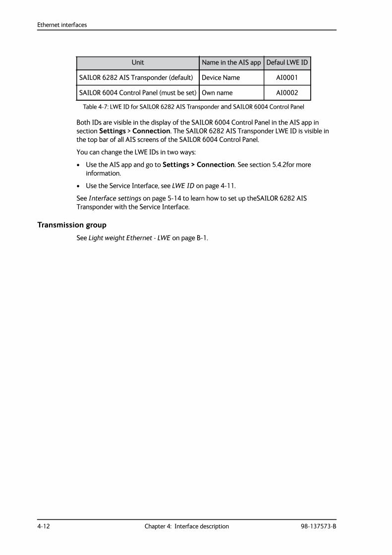
Ethernet interfaces
4-12 Chapter 4: Interface description 98-137573-B
Both IDs are visible in the display of the SAILOR 6004 Control Panel in the AIS app in section Settings > Connection. The SAILOR 6282 AIS Transponder LWE ID is visible in the top bar of all AIS screens of the SAILOR 6004 Control Panel.
You can change the LWE IDs in two ways:
• Use the AIS app and go to Settings > Connection. See section 5.4.2for more information.
• Use the Service Interface, see LWE ID on page 4-11.
See Interface settings on page 5-14 to learn how to set up theSAILOR 6282 AIS Transponder with the Service Interface.
Transmission group
See Light weight Ethernet - LWE on page B-1.
Unit Name in the AIS app Defaul LWE ID
SAILOR 6282 AIS Transponder (default) Device Name AI0001
SAILOR 6004 Control Panel (must be set) Own name AI0002
Table 4-7: LWE ID for SAILOR 6282 AIS Transponder and SAILOR 6004 Control Panel
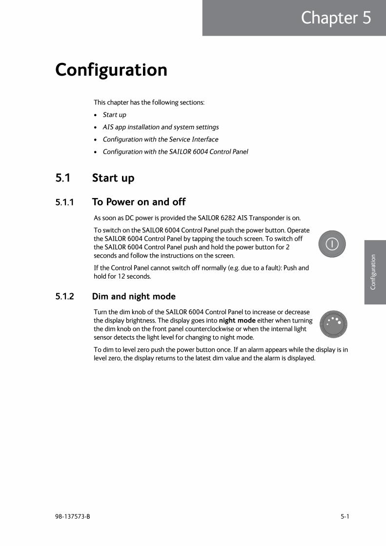
98-137573-B 5-1
Chapter 55555
Conf
igur
atio
n
Configuration 5
This chapter has the following sections:
• Start up
• AIS app installation and system settings
• Configuration with the Service Interface
• Configuration with the SAILOR 6004 Control Panel
5.1 Start up
5.1.1 To Power on and offAs soon as DC power is provided the SAILOR 6282 AIS Transponder is on.
To switch on the SAILOR 6004 Control Panel push the power button. Operate the SAILOR 6004 Control Panel by tapping the touch screen. To switch off the SAILOR 6004 Control Panel push and hold the power button for 2 seconds and follow the instructions on the screen.
If the Control Panel cannot switch off normally (e.g. due to a fault): Push and hold for 12 seconds.
5.1.2 Dim and night mode
Turn the dim knob of the SAILOR 6004 Control Panel to increase or decrease the display brightness. The display goes into night mode either when turning the dim knob on the front panel counterclockwise or when the internal light sensor detects the light level for changing to night mode.
To dim to level zero push the power button once. If an alarm appears while the display is in level zero, the display returns to the latest dim value and the alarm is displayed.
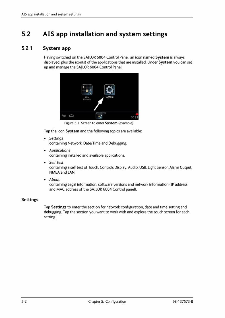
AIS app installation and system settings
5-2 Chapter 5: Configuration 98-137573-B
5.2 AIS app installation and system settings
5.2.1 System app
Having switched on the SAILOR 6004 Control Panel, an icon named System is always displayed, plus the icon(s) of the applications that are installed. Under System you can set up and manage the SAILOR 6004 Control Panel.
Tap the icon System and the following topics are available:
• Settingscontaining Network, Date/Time and Debugging.
• Applicationscontaining installed and available applications.
• Self Testcontaining a self test of Touch, Controls Display, Audio, USB, Light Sensor, Alarm Output, NMEA and LAN.
• Aboutcontaining Legal information, software versions and network information (IP address and MAC address of the SAILOR 6004 Control panel).
Settings
Tap Settings to enter the section for network configuration, date and time setting and debugging. Tap the section you want to work with and explore the touch screen for each setting.
Figure 5-1: Screen to enter System (example)
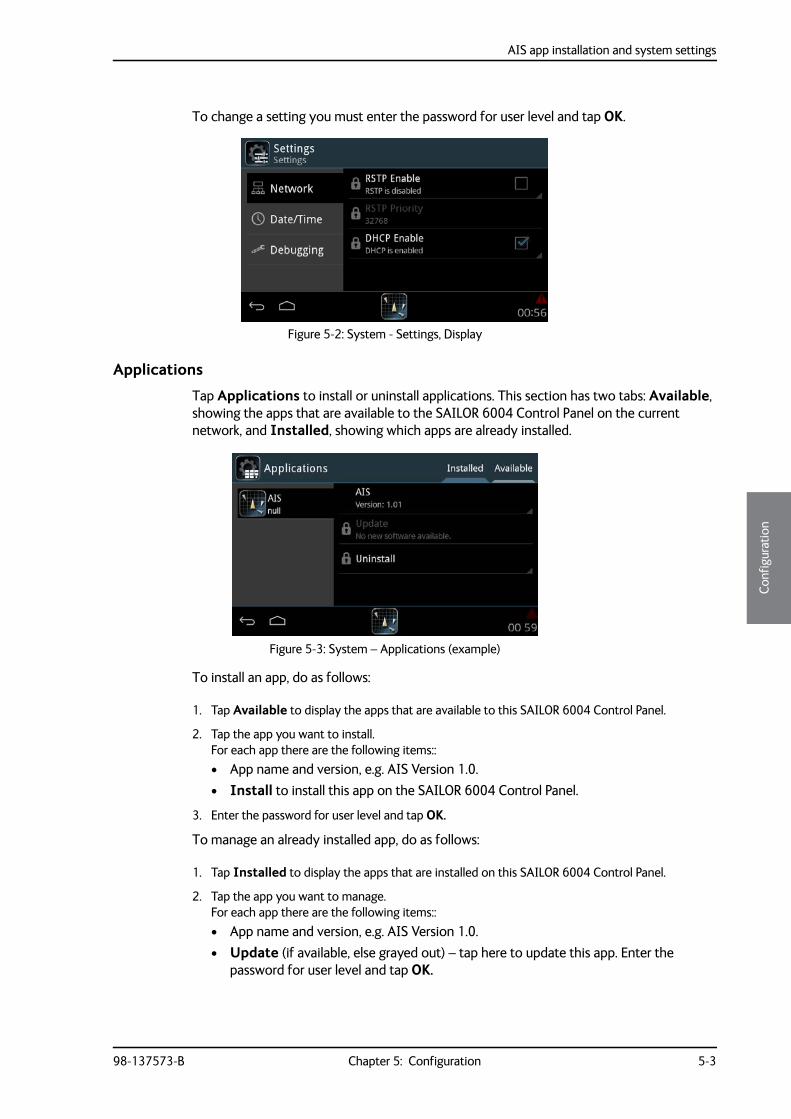
AIS app installation and system settings
98-137573-B Chapter 5: Configuration 5-3
5555
Conf
igur
atio
n
To change a setting you must enter the password for user level and tap OK.
Applications
Tap Applications to install or uninstall applications. This section has two tabs: Available, showing the apps that are available to the SAILOR 6004 Control Panel on the current network, and Installed, showing which apps are already installed.
To install an app, do as follows:
1. Tap Available to display the apps that are available to this SAILOR 6004 Control Panel.
2. Tap the app you want to install. For each app there are the following items::• App name and version, e.g. AIS Version 1.0.• Install to install this app on the SAILOR 6004 Control Panel.
3. Enter the password for user level and tap OK.
To manage an already installed app, do as follows:
1. Tap Installed to display the apps that are installed on this SAILOR 6004 Control Panel.
2. Tap the app you want to manage. For each app there are the following items::• App name and version, e.g. AIS Version 1.0.• Update (if available, else grayed out) – tap here to update this app. Enter the
password for user level and tap OK.
Figure 5-2: System - Settings, Display
Figure 5-3: System – Applications (example)
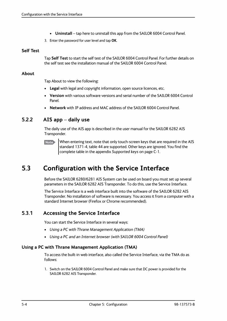
Configuration with the Service Interface
5-4 Chapter 5: Configuration 98-137573-B
• Uninstall – tap here to uninstall this app from the SAILOR 6004 Control Panel.
3. Enter the password for user level and tap OK.
Self Test
Tap Self Test to start the self test of the SAILOR 6004 Control Panel. For further details on the self test see the installation manual of the SAILOR 6004 Control Panel.
About
Tap About to view the following:
• Legal with legal and copyright information, open source licences, etc.
• Version with various software versions and serial number of the SAILOR 6004 Control Panel.
• Network with IP address and MAC address of the SAILOR 6004 Control Panel.
5.2.2 AIS app – daily use
The daily use of the AIS app is described in the user manual for the SAILOR 6282 AIS Transponder.
5.3 Configuration with the Service InterfaceBefore the SAILOR 6280/6281 AIS System can be used on board you must set up several parameters in the SAILOR 6282 AIS Transponder. To do this, use the Service Interface.
The Service Interface is a web interface built into the software of the SAILOR 6282 AIS Transponder. No installation of software is necessary. You access it from a computer with a standard Internet browser (Firefox or Chrome recommended).
5.3.1 Accessing the Service Interface
You can start the Service Interface in several ways:
• Using a PC with Thrane Management Application (TMA)
• Using a PC and an Internet browser (with SAILOR 6004 Control Panel)
Using a PC with Thrane Management Application (TMA)
To access the built-in web interface, also called the Service Interface, via the TMA do as follows:
1. Switch on the SAILOR 6004 Control Panel and make sure that DC power is provided for the SAILOR 6282 AIS Transponder.
Note When entering text, note that only touch-screen keys that are required in the AIS standard 1371-4, table 44 are supported. Other keys are ignored. You find the complete table in the appendix Supported keys on page C-1.
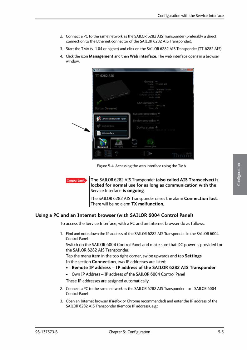
Configuration with the Service Interface
98-137573-B Chapter 5: Configuration 5-5
5555
Conf
igur
atio
n
2. Connect a PC to the same network as the SAILOR 6282 AIS Transponder (preferably a direct connection to the Ethernet connector of the SAILOR 6282 AIS Transponder).
3. Start the TMA (v. 1.04 or higher) and click on the SAILOR 6282 AIS Transponder (TT-6282 AIS).
4. Click the icon Management and then Web interface. The web interface opens in a browser window.
Using a PC and an Internet browser (with SAILOR 6004 Control Panel)
To access the Service Interface, with a PC and an Internet browser do as follows:
1. Find and note down the IP address of the SAILOR 6282 AIS Transponder. in the SAILOR 6004 Control Panel.Switch on the SAILOR 6004 Control Panel and make sure that DC power is provided for the SAILOR 6282 AIS Transponder.Tap the menu item in the top right corner, swipe upwards and tap Settings.In the section Connection, two IP addresses are listed:• Remote IP address – IP address of the SAILOR 6282 AIS Transponder• Own IP Address – IP address of the SAILOR 6004 Control PanelThese IP addresses are assigned automatically.
2. Connect a PC to the same network as the SAILOR 6282 AIS Transponder - or - SAILOR 6004 Control Panel.
3. Open an Internet browser (Firefox or Chrome recommended) and enter the IP address of the SAILOR 6282 AIS Transponder (Remote IP address), e.g.:
Figure 5-4: Accessing the web interface using the TMA
Important The SAILOR 6282 AIS Transponder (also called AIS Transceiver) is locked for normal use for as long as communication with the Service Interface is ongoing.
The SAILOR 6282 AIS Transponder raises the alarm Connection lost. There will be no alarm TX malfunction.
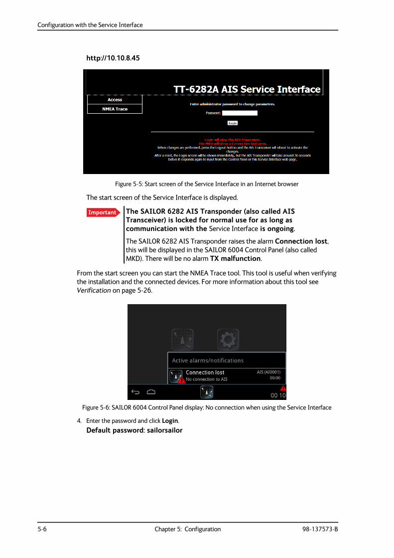
Configuration with the Service Interface
5-6 Chapter 5: Configuration 98-137573-B
http://10.10.8.45
The start screen of the Service Interface is displayed.
From the start screen you can start the NMEA Trace tool. This tool is useful when verifying the installation and the connected devices. For more information about this tool see Verification on page 5-26.
4. Enter the password and click Login.Default password: sailorsailor
Figure 5-5: Start screen of the Service Interface in an Internet browser
Important The SAILOR 6282 AIS Transponder (also called AIS Transceiver) is locked for normal use for as long as communication with the Service Interface is ongoing.
The SAILOR 6282 AIS Transponder raises the alarm Connection lost, this will be displayed in the SAILOR 6004 Control Panel (also called MKD). There will be no alarm TX malfunction.
Figure 5-6: SAILOR 6004 Control Panel display: No connection when using the Service Interface
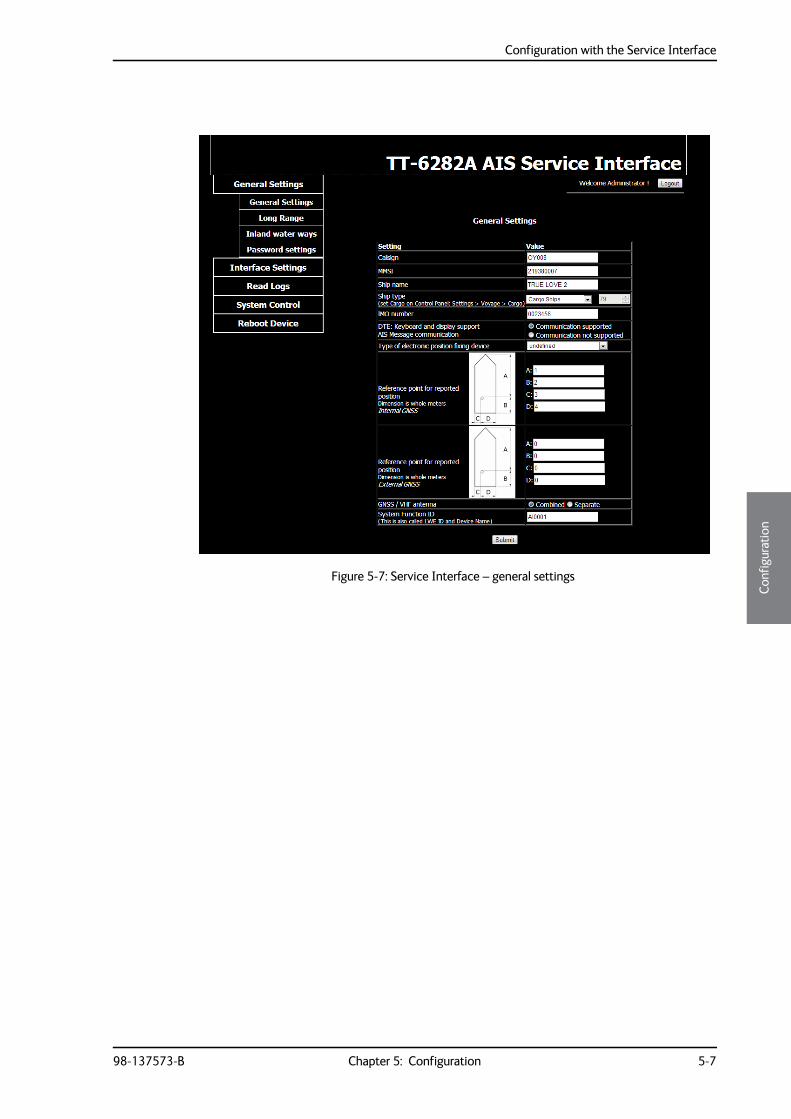
Configuration with the Service Interface
98-137573-B Chapter 5: Configuration 5-7
5555
Conf
igur
atio
n
Figure 5-7: Service Interface – general settings
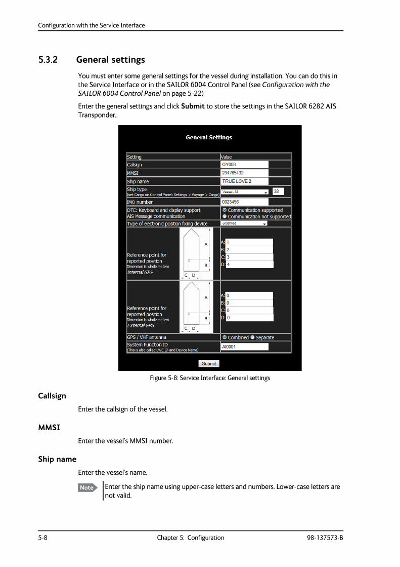
Configuration with the Service Interface
5-8 Chapter 5: Configuration 98-137573-B
5.3.2 General settings
You must enter some general settings for the vessel during installation. You can do this in the Service Interface or in the SAILOR 6004 Control Panel (see Configuration with the SAILOR 6004 Control Panel on page 5-22)
Enter the general settings and click Submit to store the settings in the SAILOR 6282 AIS Transponder..
Callsign
Enter the callsign of the vessel.
MMSI
Enter the vessel’s MMSI number.
Ship name
Enter the vessel’s name.
Figure 5-8: Service Interface: General settings
Note Enter the ship name using upper-case letters and numbers. Lower-case letters are not valid.
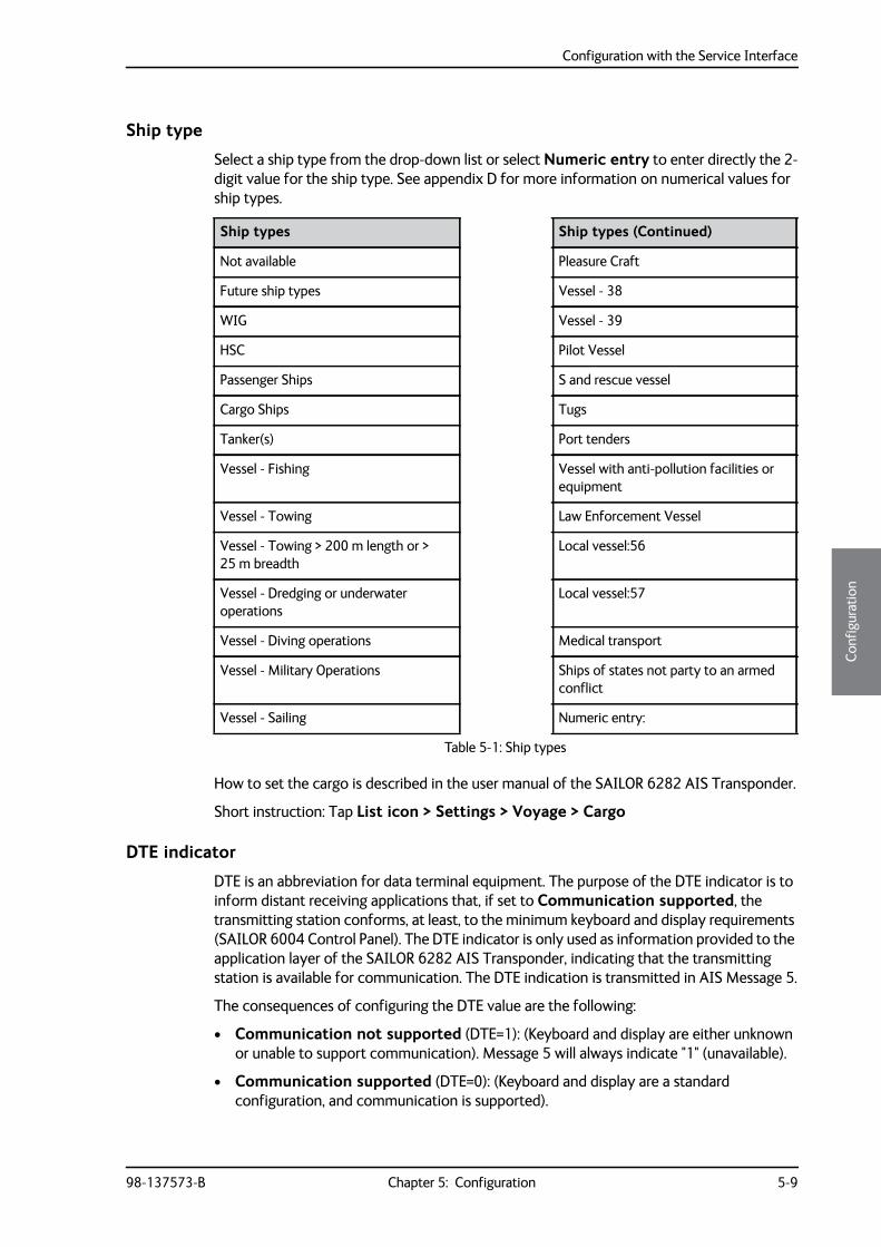
Configuration with the Service Interface
98-137573-B Chapter 5: Configuration 5-9
5555
Conf
igur
atio
n
Ship type
Select a ship type from the drop-down list or select Numeric entry to enter directly the 2-digit value for the ship type. See appendix D for more information on numerical values for ship types.
How to set the cargo is described in the user manual of the SAILOR 6282 AIS Transponder.
Short instruction: Tap List icon > Settings > Voyage > Cargo
DTE indicator
DTE is an abbreviation for data terminal equipment. The purpose of the DTE indicator is to inform distant receiving applications that, if set to Communication supported, the transmitting station conforms, at least, to the minimum keyboard and display requirements (SAILOR 6004 Control Panel). The DTE indicator is only used as information provided to the application layer of the SAILOR 6282 AIS Transponder, indicating that the transmitting station is available for communication. The DTE indication is transmitted in AIS Message 5.
The consequences of configuring the DTE value are the following:
• Communication not supported (DTE=1): (Keyboard and display are either unknown or unable to support communication). Message 5 will always indicate "1" (unavailable).
• Communication supported (DTE=0): (Keyboard and display are a standard configuration, and communication is supported).
Ship types Ship types (Continued)
Not available Pleasure Craft
Future ship types Vessel - 38
WIG Vessel - 39
HSC Pilot Vessel
Passenger Ships S and rescue vessel
Cargo Ships Tugs
Tanker(s) Port tenders
Vessel - Fishing Vessel with anti-pollution facilities or equipment
Vessel - Towing Law Enforcement Vessel
Vessel - Towing > 200 m length or > 25 m breadth
Local vessel:56
Vessel - Dredging or underwater operations
Local vessel:57
Vessel - Diving operations Medical transport
Vessel - Military Operations Ships of states not party to an armed conflict
Vessel - Sailing Numeric entry:
Table 5-1: Ship types
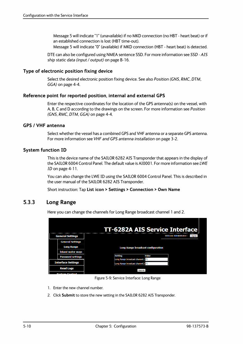
Configuration with the Service Interface
5-10 Chapter 5: Configuration 98-137573-B
Message 5 will indicate "1" (unavailable) if no MKD connection (no HBT - heart beat) or if an established connection is lost (HBT time-out).Message 5 will indicate "0" (available) if MKD connection (HBT - heart beat) is detected.
DTE can also be configured using NMEA sentence SSD. For more information see SSD - AIS ship static data (input / output) on page B-16.
Type of electronic position fixing device
Select the desired electronic position fixing device. See also Position (GNS, RMC, DTM, GGA) on page 4-4.
Reference point for reported position, internal and external GPS
Enter the respective coordinates for the location of the GPS antenna(s) on the vessel, with A, B, C and D according to the drawings on the screen. For more information see Position (GNS, RMC, DTM, GGA) on page 4-4.
GPS / VHF antenna
Select whether the vessel has a combined GPS and VHF antenna or a separate GPS antenna. For more information see VHF and GPS antenna installation on page 3-2.
System function ID
This is the device name of the SAILOR 6282 AIS Transponder that appears in the display of the SAILOR 6004 Control Panel. The default value is AI0001. For more information see LWE ID on page 4-11.
You can also change the LWE ID using the SAILOR 6004 Control Panel. This is described in the user manual of the SAILOR 6282 AIS Transponder.
Short instruction: Tap List icon > Settings > Connection > Own Name
5.3.3 Long Range
Here you can change the channels for Long Range broadcast channel 1 and 2.
1. Enter the new channel number.
2. Click Submit to store the new setting in the SAILOR 6282 AIS Transponder.
Figure 5-9: Service Interface: Long Range
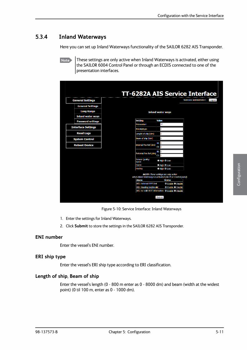
Configuration with the Service Interface
98-137573-B Chapter 5: Configuration 5-11
5555
Conf
igur
atio
n
5.3.4 Inland Waterways
Here you can set up Inland Waterways functionality of the SAILOR 6282 AIS Transponder.
1. Enter the settings for Inland Waterways.
2. Click Submit to store the settings in the SAILOR 6282 AIS Transponder.
ENI number
Enter the vessel’s ENI number.
ERI ship type
Enter the vessel’s ERI ship type according to ERI classification.
Length of ship, Beam of ship
Enter the vessel’s length (0 - 800 m enter as 0 - 8000 dm) and beam (width at the widest point) (0 til 100 m, enter as 0 - 1000 dm).
Note These settings are only active when Inland Waterways is activated, either using the SAILOR 6004 Control Panel or through an ECDIS connected to one of the presentation interfaces.
Figure 5-10: Service Interface: Inland Waterways
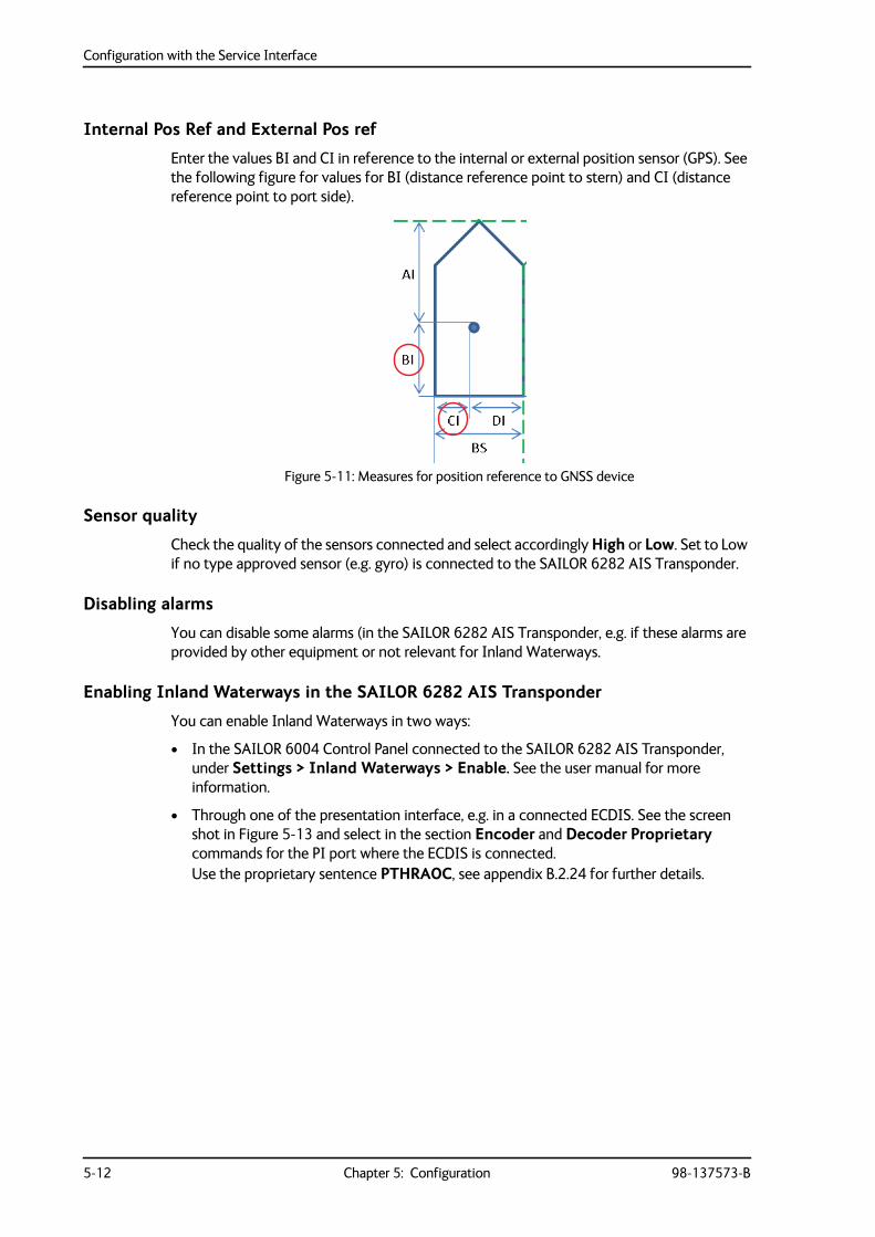
Configuration with the Service Interface
5-12 Chapter 5: Configuration 98-137573-B
Internal Pos Ref and External Pos ref
Enter the values BI and CI in reference to the internal or external position sensor (GPS). See the following figure for values for BI (distance reference point to stern) and CI (distance reference point to port side).
Sensor quality
Check the quality of the sensors connected and select accordingly High or Low. Set to Low if no type approved sensor (e.g. gyro) is connected to the SAILOR 6282 AIS Transponder.
Disabling alarms
You can disable some alarms (in the SAILOR 6282 AIS Transponder, e.g. if these alarms are provided by other equipment or not relevant for Inland Waterways.
Enabling Inland Waterways in the SAILOR 6282 AIS Transponder
You can enable Inland Waterways in two ways:
• In the SAILOR 6004 Control Panel connected to the SAILOR 6282 AIS Transponder, under Settings > Inland Waterways > Enable. See the user manual for more information.
• Through one of the presentation interface, e.g. in a connected ECDIS. See the screen shot in Figure 5-13 and select in the section Encoder and Decoder Proprietary commands for the PI port where the ECDIS is connected.Use the proprietary sentence PTHRAOC, see appendix B.2.24 for further details.
Figure 5-11: Measures for position reference to GNSS device
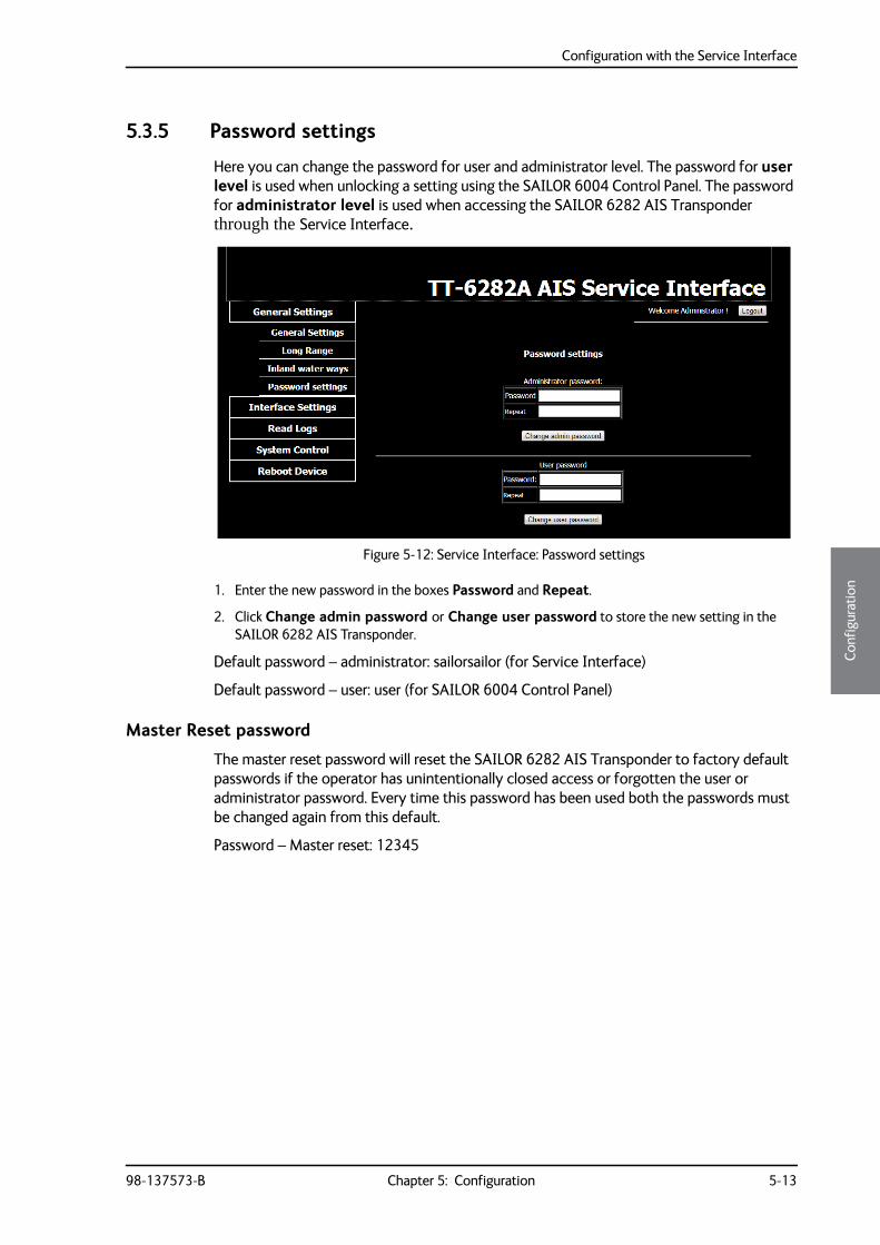
Configuration with the Service Interface
98-137573-B Chapter 5: Configuration 5-13
5555
Conf
igur
atio
n
5.3.5 Password settings
Here you can change the password for user and administrator level. The password for user level is used when unlocking a setting using the SAILOR 6004 Control Panel. The password for administrator level is used when accessing the SAILOR 6282 AIS Transponder through the Service Interface.
1. Enter the new password in the boxes Password and Repeat.
2. Click Change admin password or Change user password to store the new setting in the SAILOR 6282 AIS Transponder.
Default password – administrator: sailorsailor (for Service Interface)
Default password – user: user (for SAILOR 6004 Control Panel)
Master Reset password
The master reset password will reset the SAILOR 6282 AIS Transponder to factory default passwords if the operator has unintentionally closed access or forgotten the user or administrator password. Every time this password has been used both the passwords must be changed again from this default.
Password – Master reset: 12345
Figure 5-12: Service Interface: Password settings

Configuration with the Service Interface
5-14 Chapter 5: Configuration 98-137573-B
5.3.6 Interface settings
The purpose of the UART interface settings is to control the information coming into the 4 PI ports and the 3 sensor input ports and to configure for the desired purposes.
PI Settings (Presentation Interface bi-directional ports)
The PI ports can be configured to encode and decode different categories/purposes:
• Sensor specific NMEA sentences
• AIS specific NMEA sentences
• Alarm specific NMEA sentences
• Proprietary NMEA sentences
• Long Range NMEA sentences1
• DGNSS input (Differential GNSS)2
If two ports are configured with the same encoder/decoder pair they are operated equally. This means if for example an AIS specific sentence is configured for output on both P1 and P2, VDO/VDM sentences will be output on both ports. If identical sentences are received from multiple sources on different input ports, they shall be filtered by their talker ID.
Query sentences will only be acknowledged on the port where the request was received.
The DGNSS configuration is only allowed to be exclusively on a single port.
1. Configure only a single PI port with LONG_RANGE parser and LONG_RANGE encoder.2. Configure only a single PI port for DGNSS parser input.
Figure 5-13: Service Interface: Interface settings – PI Settings
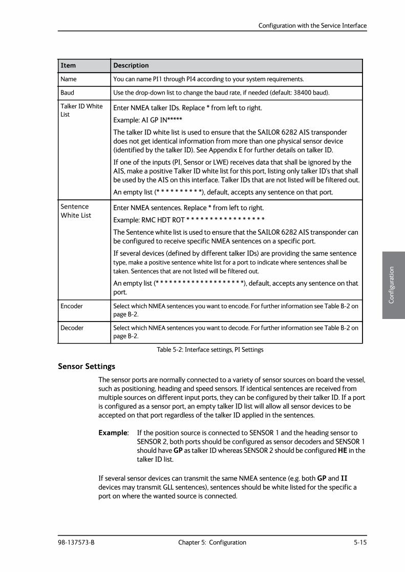
Configuration with the Service Interface
98-137573-B Chapter 5: Configuration 5-15
5555
Conf
igur
atio
n
Sensor Settings
The sensor ports are normally connected to a variety of sensor sources on board the vessel, such as positioning, heading and speed sensors. If identical sentences are received from multiple sources on different input ports, they can be configured by their talker ID. If a port is configured as a sensor port, an empty talker ID list will allow all sensor devices to be accepted on that port regardless of the talker ID applied in the sentences.
Example: If the position source is connected to SENSOR 1 and the heading sensor to SENSOR 2, both ports should be configured as sensor decoders and SENSOR 1 should have GP as talker ID whereas SENSOR 2 should be configured HE in the talker ID list.
If several sensor devices can transmit the same NMEA sentence (e.g. both GP and II devices may transmit GLL sentences), sentences should be white listed for the specific a port on where the wanted source is connected.
Item Description
Name You can name PI1 through PI4 according to your system requirements.
Baud Use the drop-down list to change the baud rate, if needed (default: 38400 baud).
Talker ID White List
Enter NMEA talker IDs. Replace * from left to right.
Example: AI GP IN*****
The talker ID white list is used to ensure that the SAILOR 6282 AIS transponder does not get identical information from more than one physical sensor device (identified by the talker ID). See Appendix E for further details on talker ID.
If one of the inputs (PI, Sensor or LWE) receives data that shall be ignored by the AIS, make a positive Talker ID white list for this port, listing only talker ID's that shall be used by the AIS on this interface. Talker IDs that are not listed will be filtered out.
An empty list (* * * * * * * * * *), default, accepts any sentence on that port.
Sentence White List
Enter NMEA sentences. Replace * from left to right.
Example: RMC HDT ROT * * * * * * * * * * * * * * * * *
The Sentence white list is used to ensure that the SAILOR 6282 AIS transponder can be configured to receive specific NMEA sentences on a specific port.
If several devices (defined by different talker IDs) are providing the same sentence type, make a positive sentence white list for a port to indicate where sentences shall be taken. Sentences that are not listed will be filtered out.
An empty list (* * * * * * * * * * * * * * * * * * * *), default, accepts any sentence on that port.
Encoder Select which NMEA sentences you want to encode. For further information see Table B-2 on page B-2.
Decoder Select which NMEA sentences you want to decode. For further information see Table B-2 on page B-2.
Table 5-2: Interface settings, PI Settings
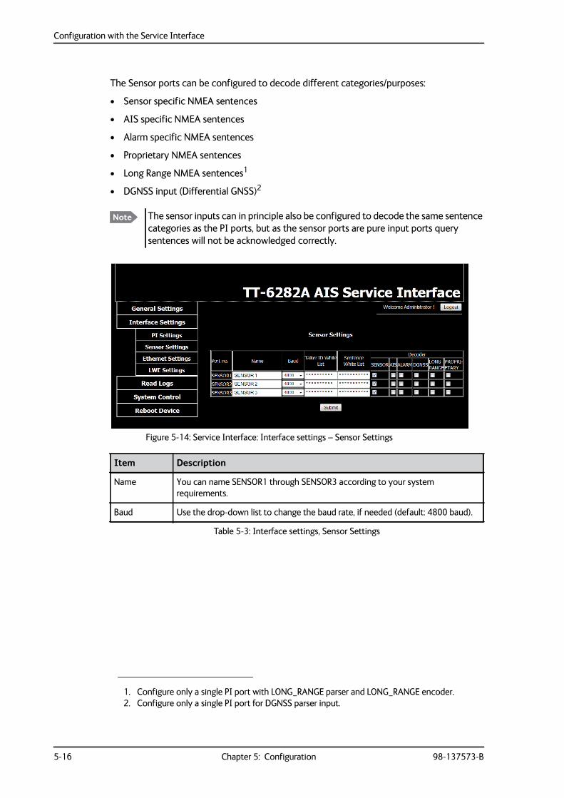
Configuration with the Service Interface
5-16 Chapter 5: Configuration 98-137573-B
The Sensor ports can be configured to decode different categories/purposes:
• Sensor specific NMEA sentences
• AIS specific NMEA sentences
• Alarm specific NMEA sentences
• Proprietary NMEA sentences
• Long Range NMEA sentences1
• DGNSS input (Differential GNSS)2
1. Configure only a single PI port with LONG_RANGE parser and LONG_RANGE encoder.2. Configure only a single PI port for DGNSS parser input.
Note The sensor inputs can in principle also be configured to decode the same sentence categories as the PI ports, but as the sensor ports are pure input ports query sentences will not be acknowledged correctly.
Figure 5-14: Service Interface: Interface settings – Sensor Settings
Item Description
Name You can name SENSOR1 through SENSOR3 according to your system requirements.
Baud Use the drop-down list to change the baud rate, if needed (default: 4800 baud).
Table 5-3: Interface settings, Sensor Settings
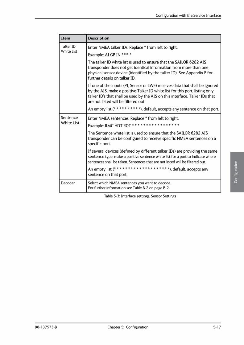
Configuration with the Service Interface
98-137573-B Chapter 5: Configuration 5-17
5555
Conf
igur
atio
n
Talker ID White List
Enter NMEA talker IDs. Replace * from left to right.
Example: AI GP IN **** *
The talker ID white list is used to ensure that the SAILOR 6282 AIS transponder does not get identical information from more than one physical sensor device (identified by the talker ID). See Appendix E for further details on talker ID.
If one of the inputs (PI, Sensor or LWE) receives data that shall be ignored by the AIS, make a positive Talker ID white list for this port, listing only talker ID's that shall be used by the AIS on this interface. Talker IDs that are not listed will be filtered out.
An empty list (* * * * * * * * * *), default, accepts any sentence on that port.
Sentence White List
Enter NMEA sentences. Replace * from left to right.
Example: RMC HDT ROT * * * * * * * * * * * * * * * * *
The Sentence white list is used to ensure that the SAILOR 6282 AIS transponder can be configured to receive specific NMEA sentences on a specific port.
If several devices (defined by different talker IDs) are providing the same sentence type, make a positive sentence white list for a port to indicate where sentences shall be taken. Sentences that are not listed will be filtered out.
An empty list (* * * * * * * * * * * * * * * * * * * *), default, accepts any sentence on that port.
Decoder Select which NMEA sentences you want to decode. For further information see Table B-2 on page B-2.
Item Description
Table 5-3: Interface settings, Sensor Settings
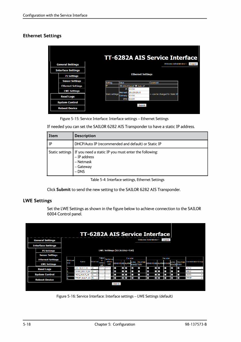
Configuration with the Service Interface
5-18 Chapter 5: Configuration 98-137573-B
Ethernet Settings
If needed you can set the SAILOR 6282 AIS Transponder to have a static IP address.
Click Submit to send the new setting to the SAILOR 6282 AIS Transponder.
LWE Settings
Set the LWE Settings as shown in the figure below to achieve connection to the SAILOR 6004 Control panel.
Figure 5-15: Service Interface: Interface settings – Ethernet Settings
Item Description
IP DHCP/Auto IP (recommended and default) or Static IP
Static settings If you need a static IP you must enter the following:– IP address– Netmask– Gateway– DNS
Table 5-4: Interface settings, Ethernet Settings
Figure 5-16: Service Interface: Interface settings – LWE Settings (default)
Configuration with the Service Interface
98-137573-B Chapter 5: Configuration 5-19
5555
Conf
igur
atio
n
Read more about LWE at LWE ID on page 4-11.
Item Description
Name You can name Multicast groups1 through 4 according to your system requirements.
Direction There are three possibilities for the multicast group:
• listen only (IN:input only),
• talk (OUT:output only)
• listen and talk (BI:bidriectional)
Talker ID White List Enter NMEA LWE source IDs. Replace * from left to right.
Example: AI0001 ZZ1234 BI0222 CC2222 GH0011 * * * * *
The talker ID white list is used to ensure that the SAILOR 6282 AIS transponder does not get identical information from more than one physical sensor device (identified by talker ID).
If one of the inputs (PI, Sensor or LWE) receives data that shall be ignored by the AIS, make a positive Talker ID white list for this port, listing only talker ID's that shall be used by the AIS on this interface. Talker IDs that are not listed will be filtered out.
An empty list (* * * * * * * * * *), default, allows input from any talker ID.
Sentence White List
Enter NMEA sentences. Replace * from left to right.
Example: RMC HDT ROT * * * * * * * * * * * * * * * * *
The Sentence white list is used to ensure that the SAILOR 6282 AIS transponder can be configured to receive specific NMEA sentences on a specific port.
If several devices (defined by different talker IDs) are providing the same sentence type, make a positive sentence white list for a port to indicate where sentences shall be taken. Sentences that are not listed will be filtered out.
An empty list (* * * * * * * * * * * * * * * * * * * *), default, accepts any sentence on that port.
Encoder Select which NMEA sentences you want to encode. For further information see Table B-2 on page B-2.
Decoder Select which NMEA sentences you want to decode. For further information see Table B-2 on page B-2.
Transmission Group Select which lightweight Ethernet transmission group to use for the telegrams to use. Transmission groups must be unique for each port. For further information see Appendix B, NMEA sentences.
Table 5-5: Interface settings, LWE Settings
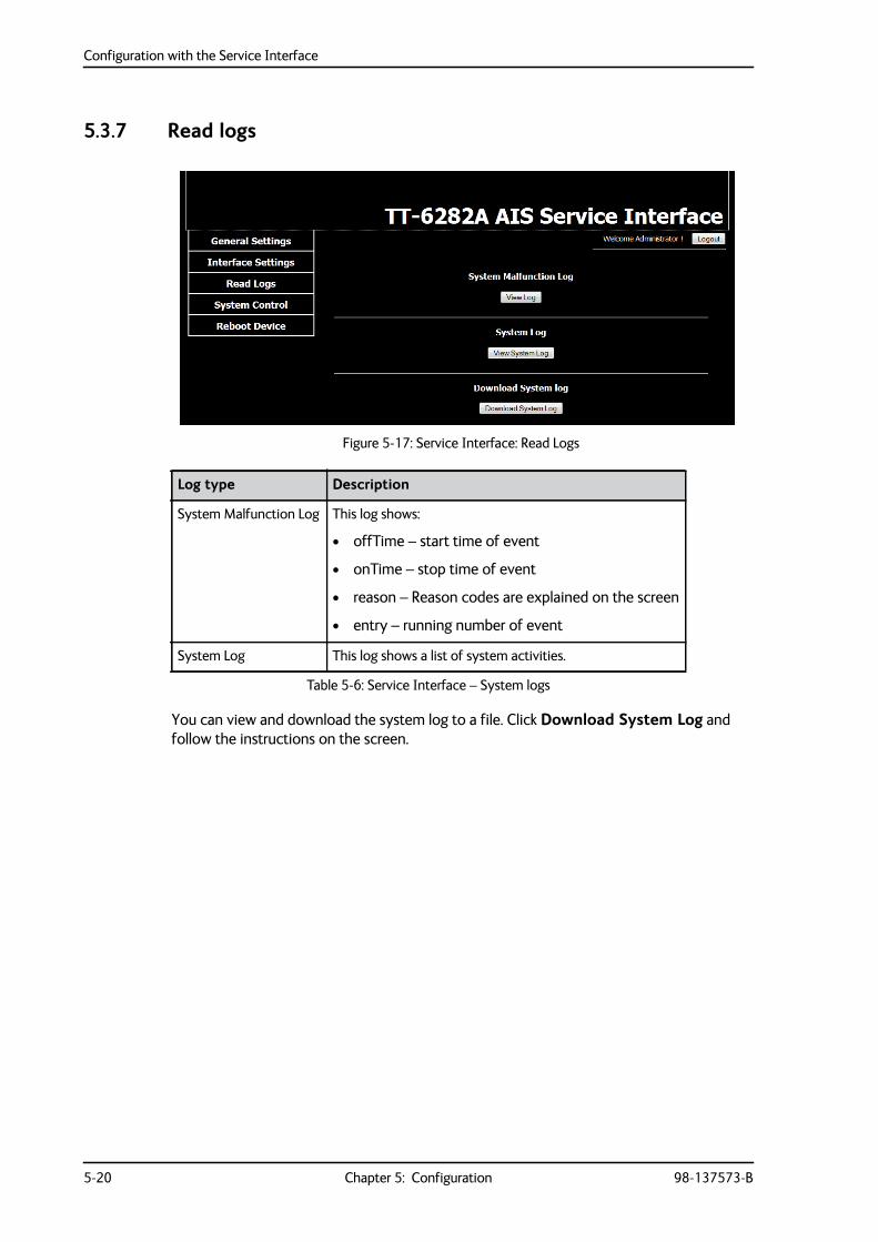
Configuration with the Service Interface
5-20 Chapter 5: Configuration 98-137573-B
5.3.7 Read logs
You can view and download the system log to a file. Click Download System Log and follow the instructions on the screen.
Figure 5-17: Service Interface: Read Logs
Log type Description
System Malfunction Log This log shows:
• offTime – start time of event
• onTime – stop time of event
• reason – Reason codes are explained on the screen
• entry – running number of event
System Log This log shows a list of system activities.
Table 5-6: Service Interface – System logs
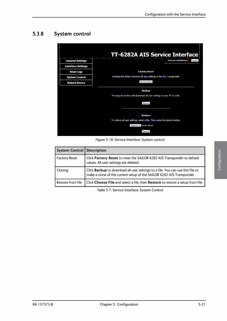
Configuration with the Service Interface
98-137573-B Chapter 5: Configuration 5-21
5555
Conf
igur
atio
n
5.3.8 System control
Figure 5-18: Service Interface: System control
System Control Description
Factory Reset Click Factory Reset to reset the SAILOR 6282 AIS Transponder to default values. All user settings are deleted.
Cloning Click Backup to download all user settings to a file. You can use this file to make a clone of the current setup of the SAILOR 6282 AIS Transponder.
Restore from file Click Choose File and select a file, then Restore to restore a setup from file.
Table 5-7: Service Interface: System Control
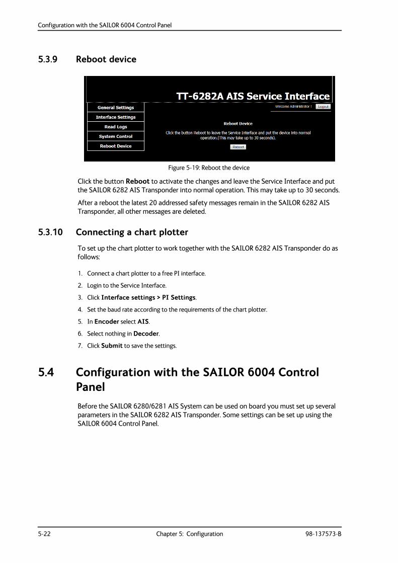
Configuration with the SAILOR 6004 Control Panel
5-22 Chapter 5: Configuration 98-137573-B
5.3.9 Reboot device
Click the button Reboot to activate the changes and leave the Service Interface and put the SAILOR 6282 AIS Transponder into normal operation. This may take up to 30 seconds.
After a reboot the latest 20 addressed safety messages remain in the SAILOR 6282 AIS Transponder, all other messages are deleted.
5.3.10 Connecting a chart plotter
To set up the chart plotter to work together with the SAILOR 6282 AIS Transponder do as follows:
1. Connect a chart plotter to a free PI interface.
2. Login to the Service Interface.
3. Click Interface settings > PI Settings.
4. Set the baud rate according to the requirements of the chart plotter.
5. In Encoder select AIS.
6. Select nothing in Decoder.
7. Click Submit to save the settings.
5.4 Configuration with the SAILOR 6004 Control PanelBefore the SAILOR 6280/6281 AIS System can be used on board you must set up several parameters in the SAILOR 6282 AIS Transponder. Some settings can be set up using the SAILOR 6004 Control Panel.
Figure 5-19: Reboot the device
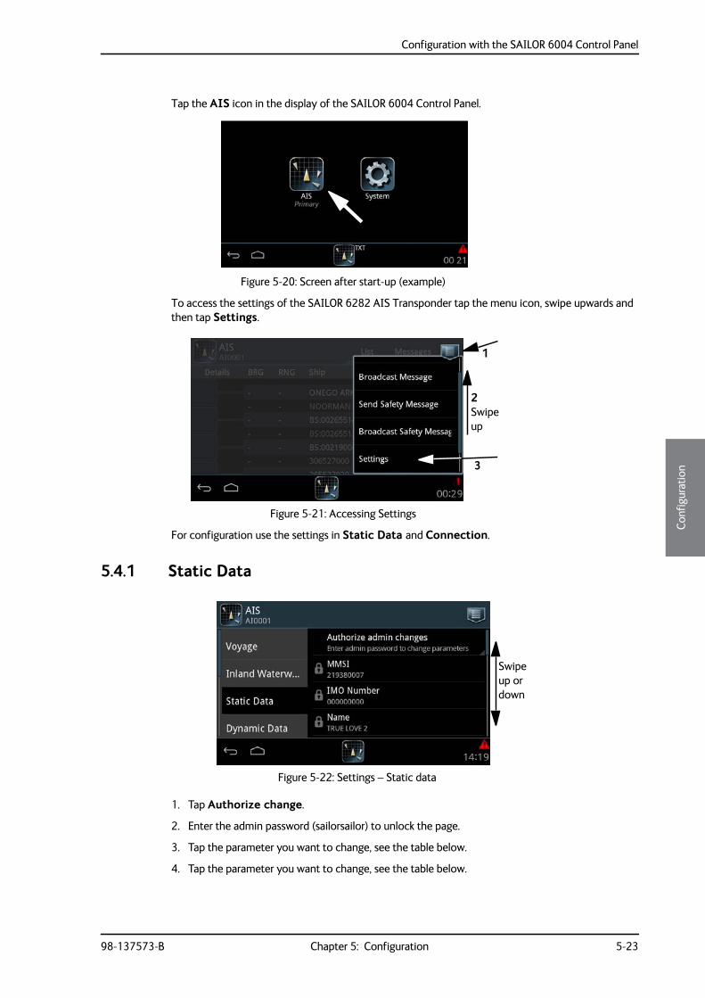
Configuration with the SAILOR 6004 Control Panel
98-137573-B Chapter 5: Configuration 5-23
5555
Conf
igur
atio
n
Tap the AIS icon in the display of the SAILOR 6004 Control Panel.
To access the settings of the SAILOR 6282 AIS Transponder tap the menu icon, swipe upwards and then tap Settings.
For configuration use the settings in Static Data and Connection.
5.4.1 Static Data
1. Tap Authorize change.
2. Enter the admin password (sailorsailor) to unlock the page.
3. Tap the parameter you want to change, see the table below.
4. Tap the parameter you want to change, see the table below.
Figure 5-20: Screen after start-up (example)
Figure 5-21: Accessing Settings
1
3
2Swipe up
Figure 5-22: Settings – Static data
Swipe up or down
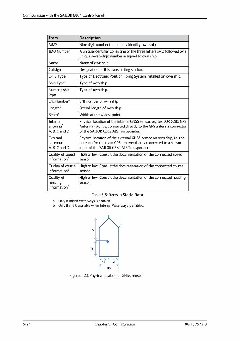
Configuration with the SAILOR 6004 Control Panel
5-24 Chapter 5: Configuration 98-137573-B
Item Description
MMSI Nine digit number to uniquely identify own ship.
IMO Number A unique identifier consisting of the three letters IMO followed by a unique seven-digit number assigned to own ship.
Name Name of own ship.
Callsign Designation of this transmitting station.
EPFS Type Type of Electronic Position Fixing System installed on own ship.
Ship Type Type of own ship.
Numeric ship type
Type of own ship.
ENI Numbera
a. Only if Inland Waterways is enabled.
ENI number of own ship
Lengtha Overall length of own ship.
Beama Width at the widest point.
Internal antennab A, B, C and D
b. Only B and C available when Internal Waterways is enabled.
Physical location of the internal GNSS sensor, e.g. SAILOR 6285 GPS Antenna - Active, connected directly to the GPS antenna connector of the SAILOR 6282 AIS Transponder.
External antennab
A, B, C and D
Physical location of the external GNSS sensor on own ship, i.e. the antenna for the main GPS receiver that is connected to a sensor input of the SAILOR 6282 AIS Transponder.
Quality of speed informationa
High or low. Consult the documentation of the connected speed sensor.
Quality of course informationa
High or low. Consult the documentation of the connected course sensor.
Quality of heading informationa
High or low. Consult the documentation of the connected heading sensor.
Table 5-8: Items in Static Data
Figure 5-23: Physical location of GNSS sensor
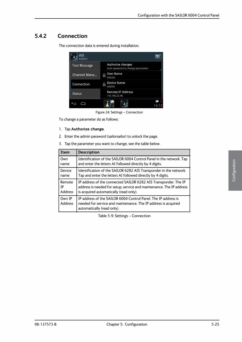
Configuration with the SAILOR 6004 Control Panel
98-137573-B Chapter 5: Configuration 5-25
5555
Conf
igur
atio
n
5.4.2 Connection
The connection data is entered during installation.
To change a parameter do as follows:
1. Tap Authorize change.
2. Enter the admin password (sailorsailor) to unlock the page.
3. Tap the parameter you want to change, see the table below.
Figure 24: Settings – Connection
Item Description
Own name
Identification of the SAILOR 6004 Control Panel in the network. Tap and enter the letters AI followed directly by 4 digits.
Device name
Identification of the SAILOR 6282 AIS Transponder in the network. Tap and enter the letters AI followed directly by 4 digits.
Remote IP Address
IP address of the connected SAILOR 6282 AIS Transponder. The IP address is needed for setup, service and maintenance. The IP address is acquired automatically (read only).
Own IP Address
IP address of the SAILOR 6004 Control Panel. The IP address is needed for service and maintenance. The IP address is acquired automatically (read only).
Table 5-9: Settings – Connection
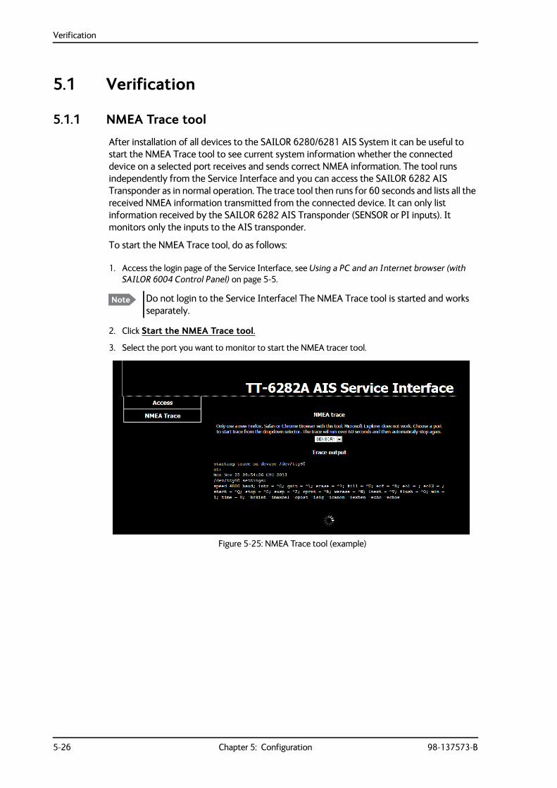
Verification
5-26 Chapter 5: Configuration 98-137573-B
5.1 Verification
5.1.1 NMEA Trace tool
After installation of all devices to the SAILOR 6280/6281 AIS System it can be useful to start the NMEA Trace tool to see current system information whether the connected device on a selected port receives and sends correct NMEA information. The tool runs independently from the Service Interface and you can access the SAILOR 6282 AIS Transponder as in normal operation. The trace tool then runs for 60 seconds and lists all the received NMEA information transmitted from the connected device. It can only list information received by the SAILOR 6282 AIS Transponder (SENSOR or PI inputs). It monitors only the inputs to the AIS transponder.
To start the NMEA Trace tool, do as follows:
1. Access the login page of the Service Interface, see Using a PC and an Internet browser (with SAILOR 6004 Control Panel) on page 5-5.
2. Click Start the NMEA Trace tool.
3. Select the port you want to monitor to start the NMEA tracer tool.
Note Do not login to the Service Interface! The NMEA Trace tool is started and works separately.
Figure 5-25: NMEA Trace tool (example)
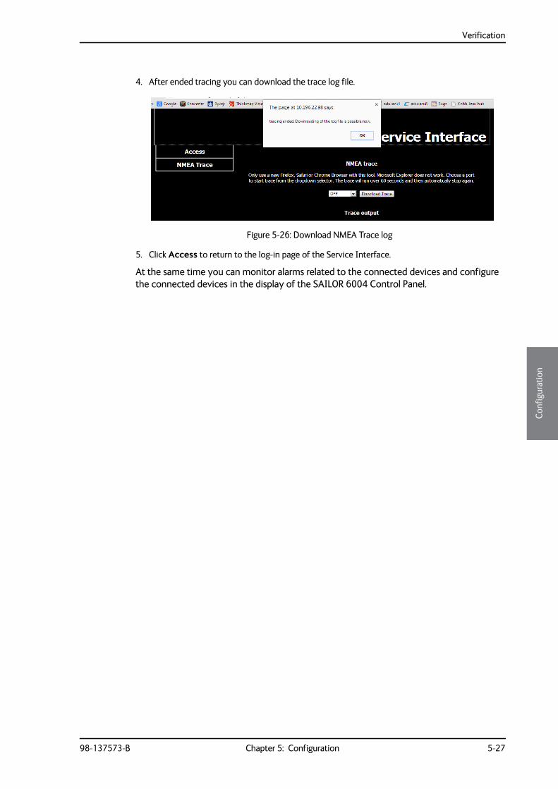
Verification
98-137573-B Chapter 5: Configuration 5-27
5555
Conf
igur
atio
n
4. After ended tracing you can download the trace log file.
5. Click Access to return to the log-in page of the Service Interface.
At the same time you can monitor alarms related to the connected devices and configure the connected devices in the display of the SAILOR 6004 Control Panel.
Figure 5-26: Download NMEA Trace log

Verification
5-28 Chapter 5: Configuration 98-137573-B
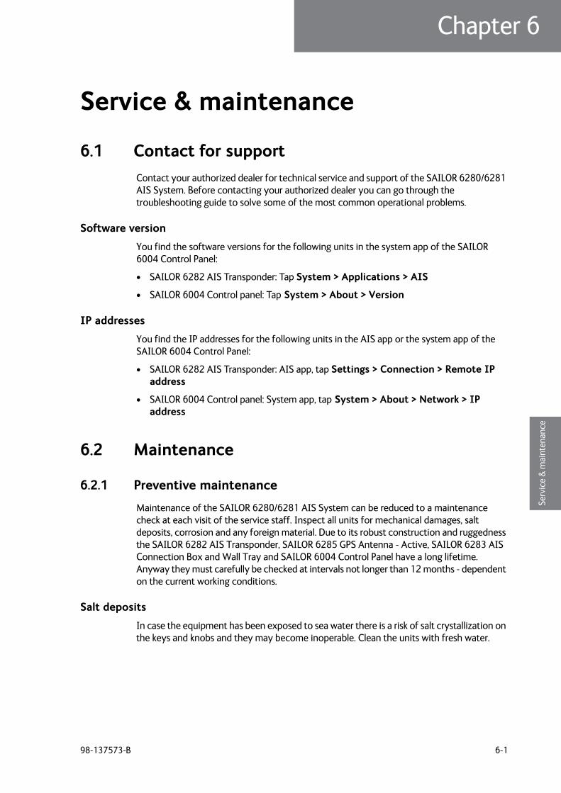
98-137573-B 6-1
Chapter 66666
Serv
ice
& m
aint
enan
ce
Service & maintenance 6
6.1 Contact for supportContact your authorized dealer for technical service and support of the SAILOR 6280/6281 AIS System. Before contacting your authorized dealer you can go through the troubleshooting guide to solve some of the most common operational problems.
Software version
You find the software versions for the following units in the system app of the SAILOR 6004 Control Panel:
• SAILOR 6282 AIS Transponder: Tap System > Applications > AIS
• SAILOR 6004 Control panel: Tap System > About > Version
IP addresses
You find the IP addresses for the following units in the AIS app or the system app of the SAILOR 6004 Control Panel:
• SAILOR 6282 AIS Transponder: AIS app, tap Settings > Connection > Remote IP address
• SAILOR 6004 Control panel: System app, tap System > About > Network > IP address
6.2 Maintenance
6.2.1 Preventive maintenance
Maintenance of the SAILOR 6280/6281 AIS System can be reduced to a maintenance check at each visit of the service staff. Inspect all units for mechanical damages, salt deposits, corrosion and any foreign material. Due to its robust construction and ruggedness the SAILOR 6282 AIS Transponder, SAILOR 6285 GPS Antenna - Active, SAILOR 6283 AIS Connection Box and Wall Tray and SAILOR 6004 Control Panel have a long lifetime. Anyway they must carefully be checked at intervals not longer than 12 months - dependent on the current working conditions.
Salt deposits
In case the equipment has been exposed to sea water there is a risk of salt crystallization on the keys and knobs and they may become inoperable. Clean the units with fresh water.
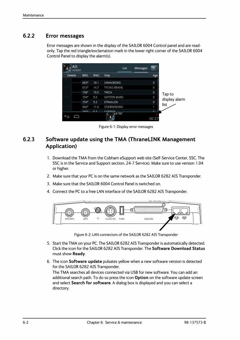
Maintenance
6-2 Chapter 6: Service & maintenance 98-137573-B
6.2.2 Error messages
Error messages are shown in the display of the SAILOR 6004 Control panel and are read-only. Tap the red triangle/exclamation mark in the lower right corner of the SAILOR 6004 Control Panel to display the alarm(s).
6.2.3 Software update using the TMA (ThraneLINK Management Application)
1. Download the TMA from the Cobham eSupport web site (Self-Service Center, SSC. The SSC is in the Service and Support section, 24-7 Service). Make sure to use version 1.04 or higher.
2. Make sure that your PC is on the same network as the SAILOR 6282 AIS Transponder.
3. Make sure that the SAILOR 6004 Control Panel is switched on.
4. Connect the PC to a free LAN interface of the SAILOR 6282 AIS Transponder.
5. Start the TMA on your PC. The SAILOR 6282 AIS Transponder is automatically detected. Click the icon for the SAILOR 6282 AIS Transponder. The Software Download Status must show Ready.
6. The icon Software update pulsates yellow when a new software version is detected for the SAILOR 6282 AIS Transponder.The TMA searches all devices connected via USB for new software. You can add an additional search path. To do so press the icon Option on the software update screen and select Search for software. A dialog box is displayed and you can select a directory.
Figure 6-1: Display error messages
Figure 6-2: LAN connectors of the SAILOR 6282 AIS Transponder
VHF/GPS GPS 12-24V DC FUSE SUB-D50
1
Tap to display alarm list
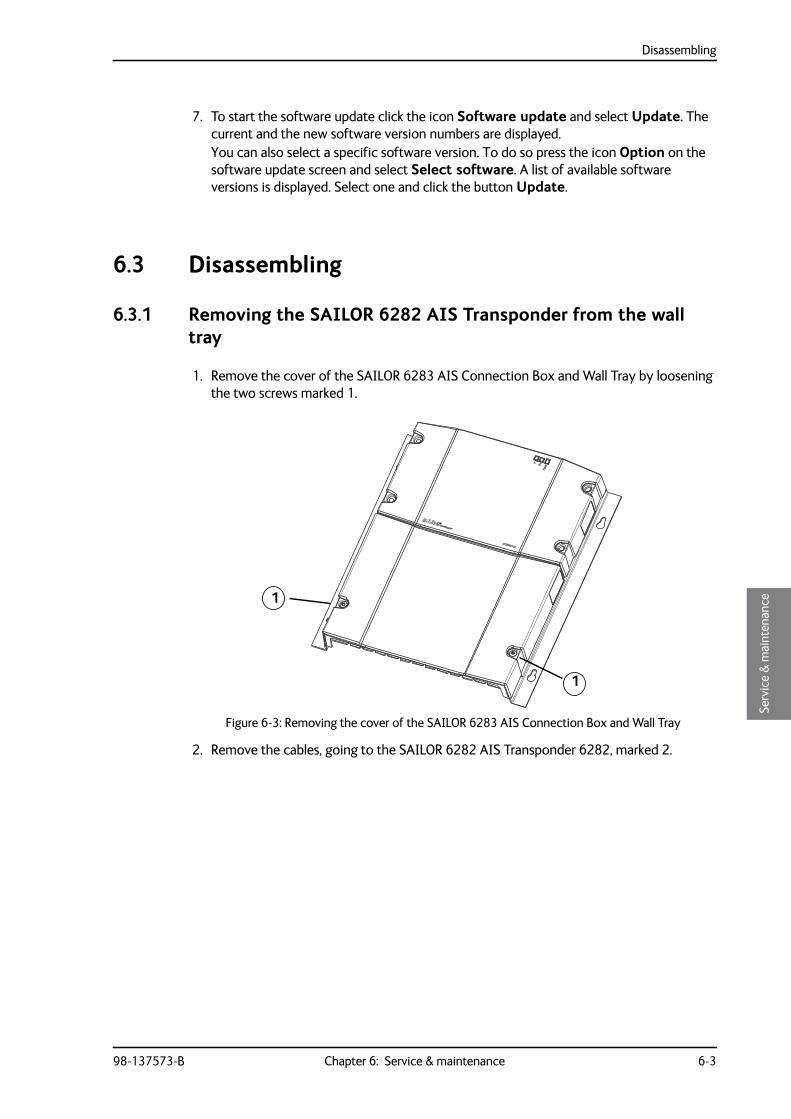
Disassembling
98-137573-B Chapter 6: Service & maintenance 6-3
6666
Serv
ice
& m
aint
enan
ce
7. To start the software update click the icon Software update and select Update. The current and the new software version numbers are displayed.You can also select a specific software version. To do so press the icon Option on the software update screen and select Select software. A list of available software versions is displayed. Select one and click the button Update.
6.3 Disassembling
6.3.1 Removing the SAILOR 6282 AIS Transponder from the wall tray
1. Remove the cover of the SAILOR 6283 AIS Connection Box and Wall Tray by loosening the two screws marked 1.
2. Remove the cables, going to the SAILOR 6282 AIS Transponder 6282, marked 2.
Figure 6-3: Removing the cover of the SAILOR 6283 AIS Connection Box and Wall Tray
1
1
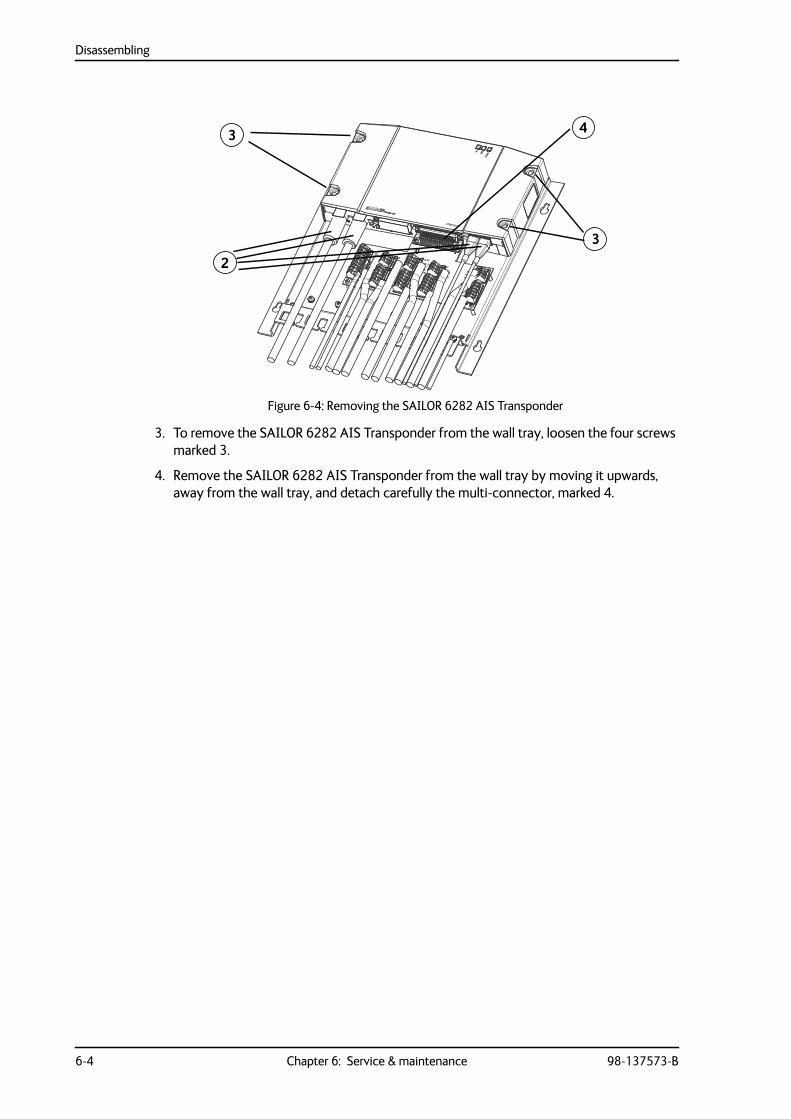
Disassembling
6-4 Chapter 6: Service & maintenance 98-137573-B
3. To remove the SAILOR 6282 AIS Transponder from the wall tray, loosen the four screws marked 3.
4. Remove the SAILOR 6282 AIS Transponder from the wall tray by moving it upwards, away from the wall tray, and detach carefully the multi-connector, marked 4.
Figure 6-4: Removing the SAILOR 6282 AIS Transponder
3
2
3
4
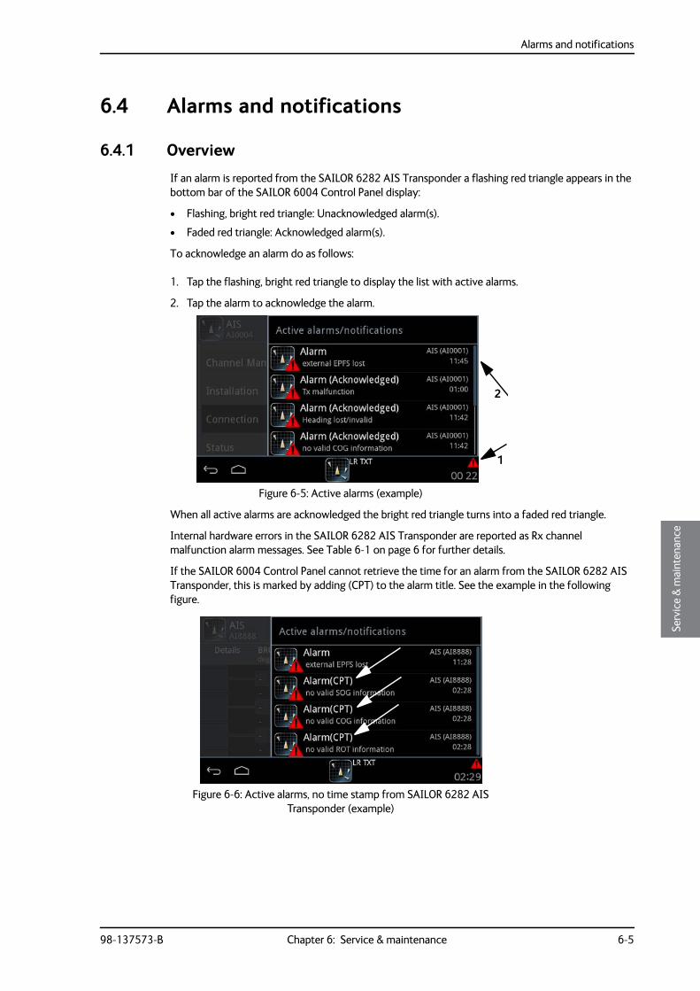
Alarms and notifications
98-137573-B Chapter 6: Service & maintenance 6-5
6666
Serv
ice
& m
aint
enan
ce
6.4 Alarms and notifications
6.4.1 Overview
If an alarm is reported from the SAILOR 6282 AIS Transponder a flashing red triangle appears in the bottom bar of the SAILOR 6004 Control Panel display:
• Flashing, bright red triangle: Unacknowledged alarm(s).
• Faded red triangle: Acknowledged alarm(s).
To acknowledge an alarm do as follows:
1. Tap the flashing, bright red triangle to display the list with active alarms.
2. Tap the alarm to acknowledge the alarm.
When all active alarms are acknowledged the bright red triangle turns into a faded red triangle.
Internal hardware errors in the SAILOR 6282 AIS Transponder are reported as Rx channel malfunction alarm messages. See Table 6-1 on page 6 for further details.
If the SAILOR 6004 Control Panel cannot retrieve the time for an alarm from the SAILOR 6282 AIS Transponder, this is marked by adding (CPT) to the alarm title. See the example in the following figure.
Figure 6-5: Active alarms (example)
Figure 6-6: Active alarms, no time stamp from SAILOR 6282 AIS Transponder (example)
1
2
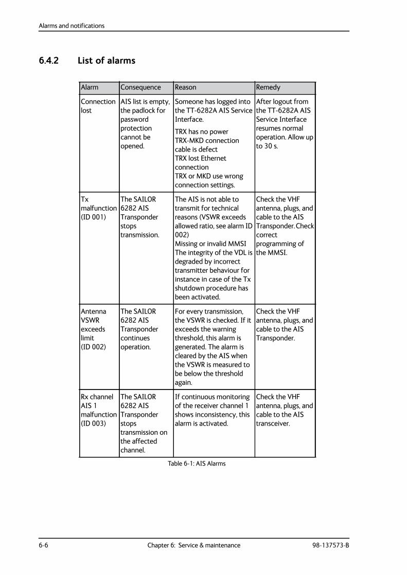
Alarms and notifications
6-6 Chapter 6: Service & maintenance 98-137573-B
6.4.2 List of alarms
Alarm Consequence Reason Remedy
Connection lost
AIS list is empty, the padlock for password protection cannot be opened.
Someone has logged into the TT-6282A AIS Service Interface.
TRX has no powerTRX-MKD connection cable is defectTRX lost Ethernet connectionTRX or MKD use wrong connection settings.
After logout from the TT-6282A AIS Service Interface resumes normal operation. Allow up to 30 s.
Tx malfunction (ID 001)
The SAILOR 6282 AIS Transponder stops transmission.
The AIS is not able to transmit for technical reasons (VSWR exceeds allowed ratio, see alarm ID 002)Missing or invalid MMSIThe integrity of the VDL is degraded by incorrect transmitter behaviour for instance in case of the Tx shutdown procedure has been activated.
Check the VHF antenna, plugs, and cable to the AIS Transponder. Check correct programming of the MMSI.
Antenna VSWR exceeds limit (ID 002)
The SAILOR 6282 AIS Transponder continues operation.
For every transmission, the VSWR is checked. If it exceeds the warning threshold, this alarm is generated. The alarm is cleared by the AIS when the VSWR is measured to be below the threshold again.
Check the VHF antenna, plugs, and cable to the AIS Transponder.
Rx channel AIS 1 malfunction (ID 003)
The SAILOR 6282 AIS Transponder stops transmission on the affected channel.
If continuous monitoring of the receiver channel 1 shows inconsistency, this alarm is activated.
Check the VHF antenna, plugs, and cable to the AIS transceiver.
Table 6-1: AIS Alarms
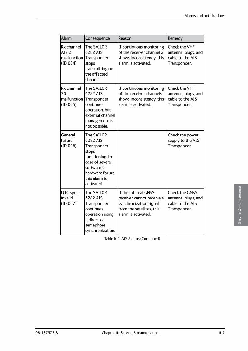
Alarms and notifications
98-137573-B Chapter 6: Service & maintenance 6-7
6666
Serv
ice
& m
aint
enan
ce
Rx channel AIS 2 malfunction (ID 004)
The SAILOR 6282 AIS Transponder stops transmitting on the affected channel.
If continuous monitoring of the receiver channel 2 shows inconsistency, this alarm is activated.
Check the VHF antenna, plugs, and cable to the AIS Transponder.
Rx channel 70 malfunction (ID 005)
The SAILOR 6282 AIS Transponder continues operation, but external channel management is not possible.
If continuous monitoring of the receiver channels shows inconsistency, this alarm is activated.
Check the VHF antenna, plugs, and cable to the AIS Transponder.
General failure (ID 006)
The SAILOR 6282 AIS Transponder stops functioning. In case of severe software or hardware failure, this alarm is activated.
Check the power supply to the AIS Transponder.
UTC sync invalid (ID 007)
The SAILOR 6282 AIS Transponder continues operation using indirect or semaphore synchronization.
If the internal GNSS receiver cannot receive a synchronization signal from the satellites, this alarm is activated.
Check the GNSS antenna, plugs, and cable to the AIS Transponder.
Alarm Consequence Reason Remedy
Table 6-1: AIS Alarms (Continued)
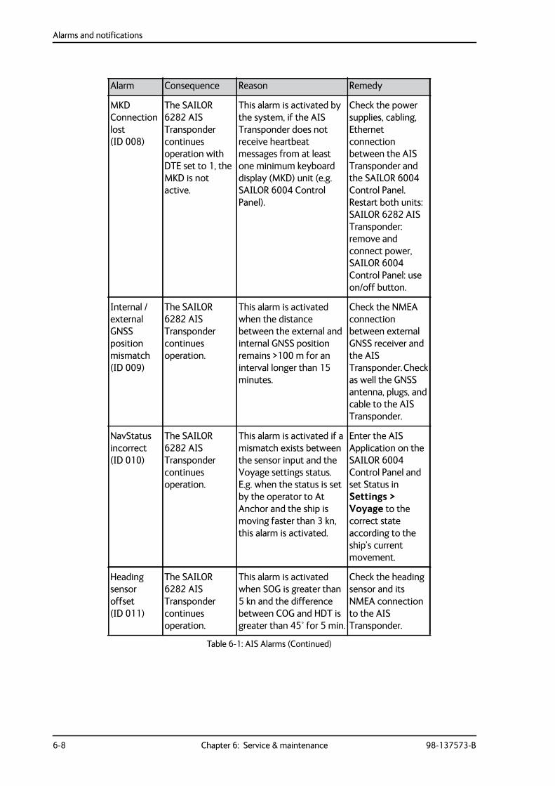
Alarms and notifications
6-8 Chapter 6: Service & maintenance 98-137573-B
MKD Connection lost (ID 008)
The SAILOR 6282 AIS Transponder continues operation with DTE set to 1, the MKD is not active.
This alarm is activated by the system, if the AIS Transponder does not receive heartbeat messages from at least one minimum keyboard display (MKD) unit (e.g. SAILOR 6004 Control Panel).
Check the power supplies, cabling, Ethernet connection between the AIS Transponder and the SAILOR 6004 Control Panel. Restart both units: SAILOR 6282 AIS Transponder: remove and connect power, SAILOR 6004 Control Panel: use on/off button.
Internal / external GNSS position mismatch (ID 009)
The SAILOR 6282 AIS Transponder continues operation.
This alarm is activated when the distance between the external and internal GNSS position remains >100 m for an interval longer than 15 minutes.
Check the NMEA connection between external GNSS receiver and the AIS Transponder. Check as well the GNSS antenna, plugs, and cable to the AIS Transponder.
NavStatus incorrect (ID 010)
The SAILOR 6282 AIS Transponder continues operation.
This alarm is activated if a mismatch exists between the sensor input and the Voyage settings status. E.g. when the status is set by the operator to At Anchor and the ship is moving faster than 3 kn, this alarm is activated.
Enter the AIS Application on the SAILOR 6004 Control Panel and set Status in Settings > Voyage to the correct state according to the ship’s current movement.
Heading sensor offset (ID 011)
The SAILOR 6282 AIS Transponder continues operation.
This alarm is activated when SOG is greater than 5 kn and the difference between COG and HDT is greater than 45° for 5 min.
Check the heading sensor and its NMEA connection to the AIS Transponder.
Alarm Consequence Reason Remedy
Table 6-1: AIS Alarms (Continued)
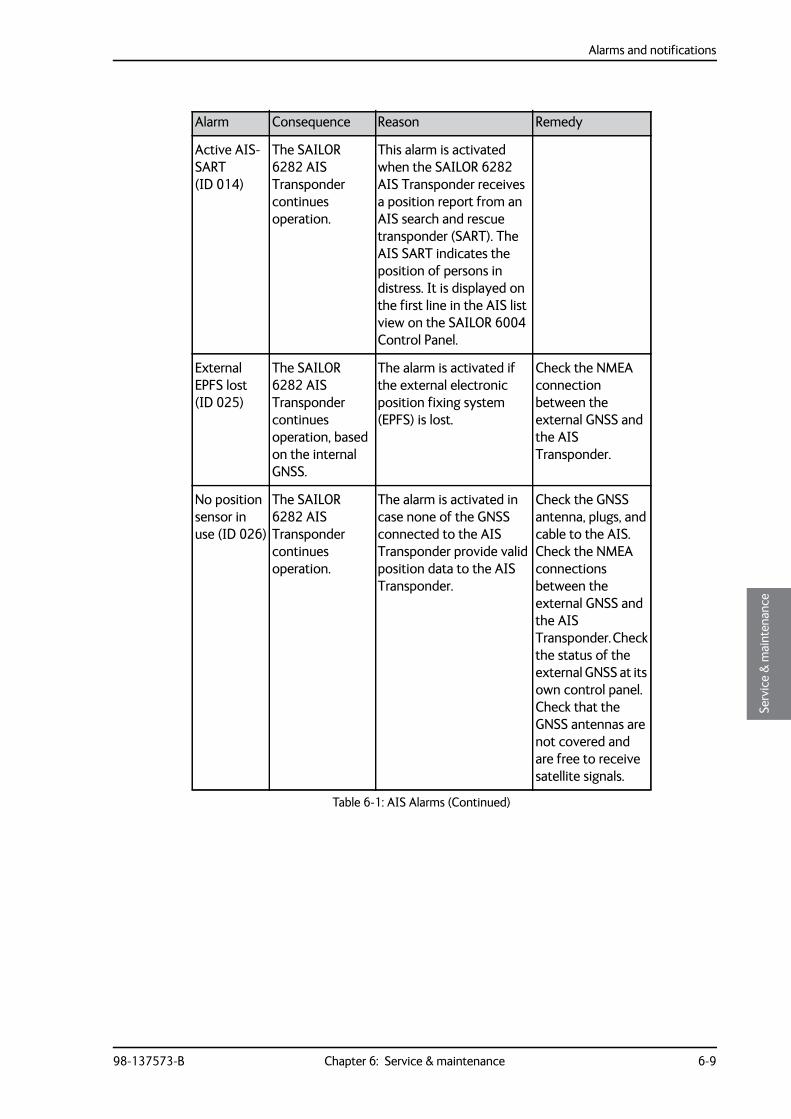
Alarms and notifications
98-137573-B Chapter 6: Service & maintenance 6-9
6666
Serv
ice
& m
aint
enan
ce
Active AIS-SART (ID 014)
The SAILOR 6282 AIS Transponder continues operation.
This alarm is activated when the SAILOR 6282 AIS Transponder receives a position report from an AIS search and rescue transponder (SART). The AIS SART indicates the position of persons in distress. It is displayed on the first line in the AIS list view on the SAILOR 6004 Control Panel.
External EPFS lost (ID 025)
The SAILOR 6282 AIS Transponder continues operation, based on the internal GNSS.
The alarm is activated if the external electronic position fixing system (EPFS) is lost.
Check the NMEA connection between the external GNSS and the AIS Transponder.
No position sensor in use (ID 026)
The SAILOR 6282 AIS Transponder continues operation.
The alarm is activated in case none of the GNSS connected to the AIS Transponder provide valid position data to the AIS Transponder.
Check the GNSS antenna, plugs, and cable to the AIS. Check the NMEA connections between the external GNSS and the AIS Transponder. Check the status of the external GNSS at its own control panel. Check that the GNSS antennas are not covered and are free to receive satellite signals.
Alarm Consequence Reason Remedy
Table 6-1: AIS Alarms (Continued)
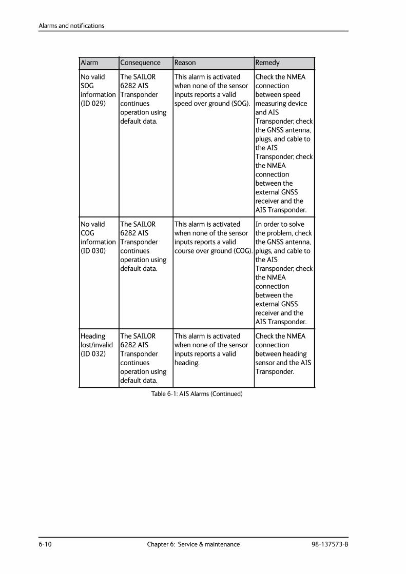
Alarms and notifications
6-10 Chapter 6: Service & maintenance 98-137573-B
No valid SOG information (ID 029)
The SAILOR 6282 AIS Transponder continues operation using default data.
This alarm is activated when none of the sensor inputs reports a valid speed over ground (SOG).
Check the NMEA connection between speed measuring device and AIS Transponder; check the GNSS antenna, plugs, and cable to the AIS Transponder; check the NMEA connection between the external GNSS receiver and the AIS Transponder.
No valid COG information (ID 030)
The SAILOR 6282 AIS Transponder continues operation using default data.
This alarm is activated when none of the sensor inputs reports a valid course over ground (COG).
In order to solve the problem, check the GNSS antenna, plugs, and cable to the AIS Transponder; check the NMEA connection between the external GNSS receiver and the AIS Transponder.
Heading lost/invalid (ID 032)
The SAILOR 6282 AIS Transponder continues operation using default data.
This alarm is activated when none of the sensor inputs reports a valid heading.
Check the NMEA connection between heading sensor and the AIS Transponder.
Alarm Consequence Reason Remedy
Table 6-1: AIS Alarms (Continued)
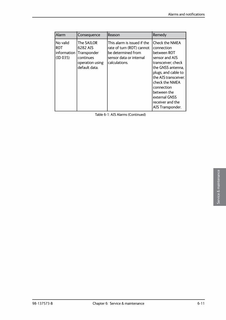
Alarms and notifications
98-137573-B Chapter 6: Service & maintenance 6-11
6666
Serv
ice
& m
aint
enan
ce
No valid ROT information (ID 035)
The SAILOR 6282 AIS Transponder continues operation using default data.
This alarm is issued if the rate of turn (ROT) cannot be determined from sensor data or internal calculations.
Check the NMEA connection between ROT sensor and AIS transceiver; check the GNSS antenna, plugs, and cable to the AIS transceiver; check the NMEA connection between the external GNSS receiver and the AIS Transponder.
Alarm Consequence Reason Remedy
Table 6-1: AIS Alarms (Continued)
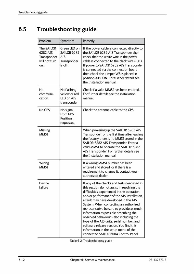
Troubleshooting guide
6-12 Chapter 6: Service & maintenance 98-137573-B
6.5 Troubleshooting guide
Problem Symptom Remedy
The SAILOR 6282 AIS Transponder will not turn on.
Green LED on SAILOR 6282 AIS Transponder is off.
If the power cable is connected directly to the SAILOR 6282 AIS Transponder then check that the white wire in the power cable is connected to the black wire (-DC). If power to SAILOR 6282 AIS Transponder is connected via the connection board then check the jumper W8 is placed in position AIS ON. For further details see the Installation manual.
No communi-cation
No flashing yellow or red LED on AIS transponder
Check if a valid MMSI has been entered. For further details see the installation manual.
No GPS No signal from GPS. Position requested.
Check the antenna cable to the GPS.
Missing MMSI
When powering up the SAILOR 6282 AIS Transponder for the first time after leaving the factory there is no MMSI stored in the SAILOR 6282 AIS Transponder. Enter a valid MMSI to operate the SAILOR 6282 AIS Transponder. For further details see the Installation manual.
Wrong MMSI
If a wrong MMSI number has been entered and stored, or if there is a requirement to change it, contact your authorized dealer.
Device failure
If any of the checks and tests described in this section do not assist in resolving the difficulties experienced in the operation and/or performance of the AIS installation, a fault may have developed in the AIS System. When contacting an authorized representative be sure to provide as much information as possible describing the observed behaviour - also including the type of the AIS units, serial number, and software release version. You find this information in the setup menu of the connected SAILOR 6004 Control Panel.
Table 6-2: Troubleshooting guide
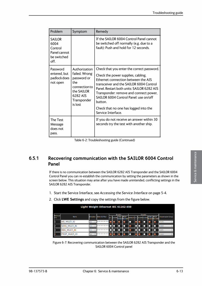
Troubleshooting guide
98-137573-B Chapter 6: Service & maintenance 6-13
6666
Serv
ice
& m
aint
enan
ce
6.5.1 Recovering communication with the SAILOR 6004 Control Panel
If there is no communication between the SAILOR 6282 AIS Transponder and the SAILOR 6004 Control Panel you can re-establish the communication by setting the parameters as shown in the screen below. This situation may arise after you have made unintended, conflicting settings in the SAILOR 6282 AIS Transponder.
1. Start the Service Interface, see Accessing the Service Interface on page 5-4.
2. Click LWE Settings and copy the settings from the figure below.
SAILOR 6004 Control Panel cannot be switched off.
If the SAILOR 6004 Control Panel cannot be switched off normally (e.g. due to a fault): Push and hold for 12 seconds.
Password entered, but padlock does not open
Authorization failed. Wrong password or the connection to the SAILOR 6282 AIS Transponder is lost
Check that you enter the correct password.
Check the power supplies, cabling, Ethernet connection between the AIS transceiver and the SAILOR 6004 Control Panel. Restart both units: SAILOR 6282 AIS Transponder: remove and connect power, SAILOR 6004 Control Panel: use on/off button.
Check that no one has logged into the Service Interface.
The Test Message does not pass.
If you do not receive an answer within 30 seconds try the test with another ship.
Problem Symptom Remedy
Table 6-2: Troubleshooting guide (Continued)
Figure 6-7: Recovering communication between the SAILOR 6282 AIS Transponder and the SAILOR 6004 Control panel
Warranty and returning units for repair
6-14 Chapter 6: Service & maintenance 98-137573-B
6.6 Warranty and returning units for repairShould your Cobham SATCOM product fail, please contact your dealer or installer, or the nearest Cobham SATCOM partner. You will find the partner details on www.cobham.com/satcom where you also find the Cobham SATCOM Self Service Center web-portal, which may help you solve the problem.
Your dealer, installer or Cobham SATCOM partner will assist you whether the need is user training, technical support, arranging on-site repair or sending the product for repair.
Your dealer, installer or Cobham SATCOM partner will also take care of any warranty issue.
6.6.1 Repacking for shipment
Should you need to send the product for repair, please read the below information before packing the product.
The shipping carton has been carefully designed to protect the SAILOR 6282 AIS Transponder and its accessories during shipment. This carton and its associated packing material should be used when repacking for shipment. Attach a tag indicating the type of service required, return address, part number and full serial number. Mark the carton FRAGILE to ensure careful handling.
If the original shipping carton is not available, the following general instructions should be used for repacking with commercially available material.
1. Wrap the defective unit in heavy paper or plastic. Attach a tag indicating the type of service required, return address, part number and full serial number.
2. Use a strong shipping container, e.g. a double walled carton.
3. Protect the front- and rear panel with cardboard and insert a layer of shock-absorbing material between all surfaces of the equipment and the sides of the container.
4. Seal the shipping container securely.
5. Mark the shipping container FRAGILE to ensure careful handling.
Failure to do so may invalidate the warranty.
Note Correct shipment is the customer’s own responsibility.
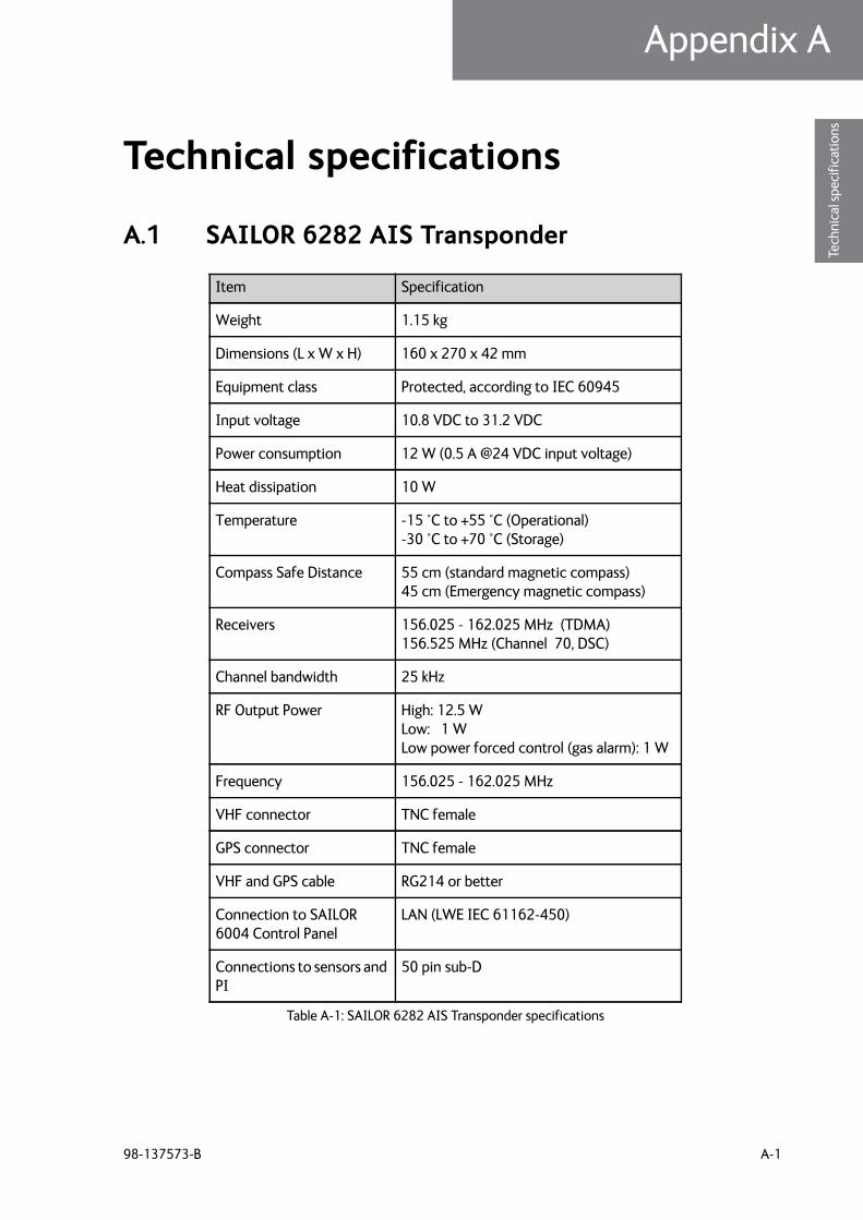
98-137573-B A-1
Appendix AAAAA
Tech
nica
l spe
cific
atio
ns
Technical specifications A
A.1 SAILOR 6282 AIS Transponder
Item Specification
Weight 1.15 kg
Dimensions (L x W x H) 160 x 270 x 42 mm
Equipment class Protected, according to IEC 60945
Input voltage 10.8 VDC to 31.2 VDC
Power consumption 12 W (0.5 A @24 VDC input voltage)
Heat dissipation 10 W
Temperature -15 °C to +55 °C (Operational) -30 °C to +70 °C (Storage)
Compass Safe Distance 55 cm (standard magnetic compass) 45 cm (Emergency magnetic compass)
Receivers 156.025 - 162.025 MHz (TDMA)156.525 MHz (Channel 70, DSC)
Channel bandwidth 25 kHz
RF Output Power High: 12.5 W Low: 1 W Low power forced control (gas alarm): 1 W
Frequency 156.025 - 162.025 MHz
VHF connector TNC female
GPS connector TNC female
VHF and GPS cable RG214 or better
Connection to SAILOR 6004 Control Panel
LAN (LWE IEC 61162-450)
Connections to sensors and PI
50 pin sub-D
Table A-1: SAILOR 6282 AIS Transponder specifications
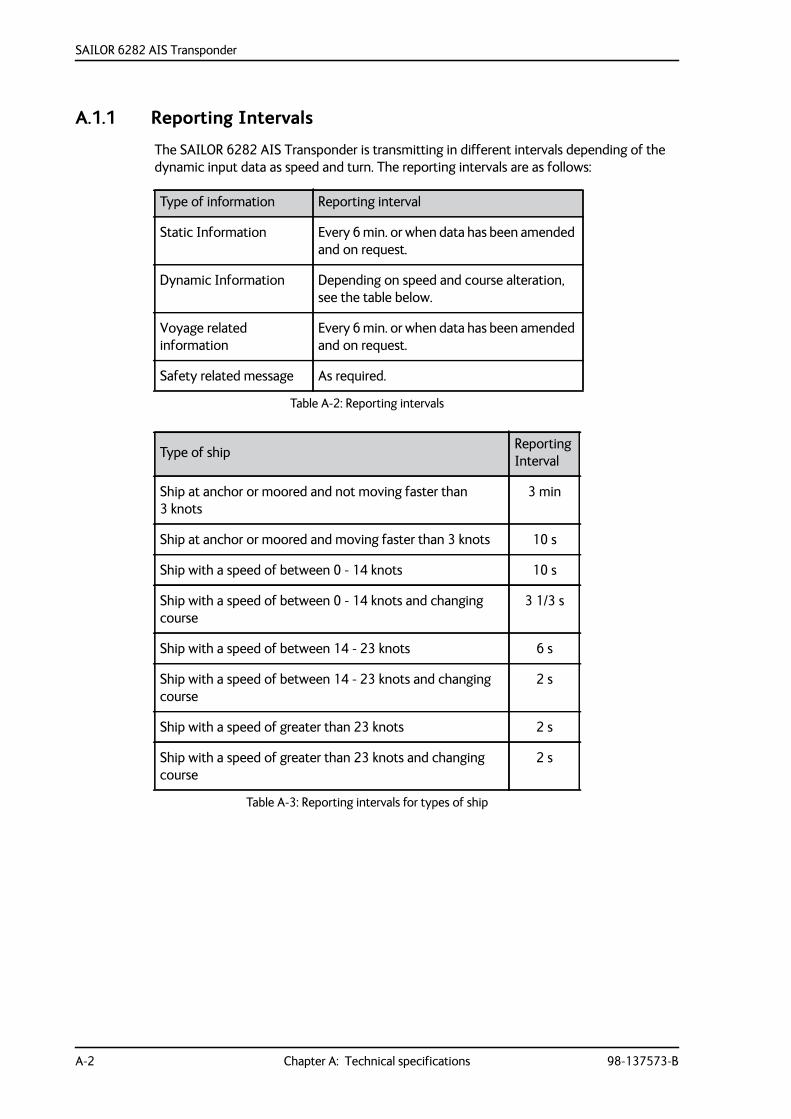
SAILOR 6282 AIS Transponder
A-2 Chapter A: Technical specifications 98-137573-B
A.1.1 Reporting Intervals
The SAILOR 6282 AIS Transponder is transmitting in different intervals depending of the dynamic input data as speed and turn. The reporting intervals are as follows:
Type of information Reporting interval
Static Information Every 6 min. or when data has been amended and on request.
Dynamic Information Depending on speed and course alteration, see the table below.
Voyage related information
Every 6 min. or when data has been amended and on request.
Safety related message As required.
Table A-2: Reporting intervals
Type of ship ReportingInterval
Ship at anchor or moored and not moving faster than 3 knots
3 min
Ship at anchor or moored and moving faster than 3 knots 10 s
Ship with a speed of between 0 - 14 knots 10 s
Ship with a speed of between 0 - 14 knots and changing course
3 1/3 s
Ship with a speed of between 14 - 23 knots 6 s
Ship with a speed of between 14 - 23 knots and changing course
2 s
Ship with a speed of greater than 23 knots 2 s
Ship with a speed of greater than 23 knots and changing course
2 s
Table A-3: Reporting intervals for types of ship
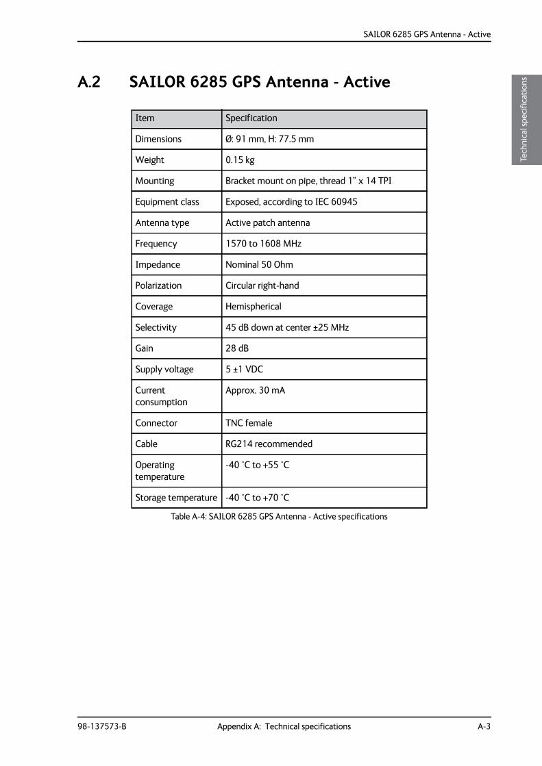
SAILOR 6285 GPS Antenna - Active
98-137573-B Appendix A: Technical specifications A-3
AAAA
Tech
nica
l spe
cific
atio
nsA.2 SAILOR 6285 GPS Antenna - Active
Item Specification
Dimensions Ø: 91 mm, H: 77.5 mm
Weight 0.15 kg
Mounting Bracket mount on pipe, thread 1” x 14 TPI
Equipment class Exposed, according to IEC 60945
Antenna type Active patch antenna
Frequency 1570 to 1608 MHz
Impedance Nominal 50 Ohm
Polarization Circular right-hand
Coverage Hemispherical
Selectivity 45 dB down at center ±25 MHz
Gain 28 dB
Supply voltage 5 ±1 VDC
Current consumption
Approx. 30 mA
Connector TNC female
Cable RG214 recommended
Operating temperature
-40 °C to +55 °C
Storage temperature -40 °C to +70 °C
Table A-4: SAILOR 6285 GPS Antenna - Active specifications
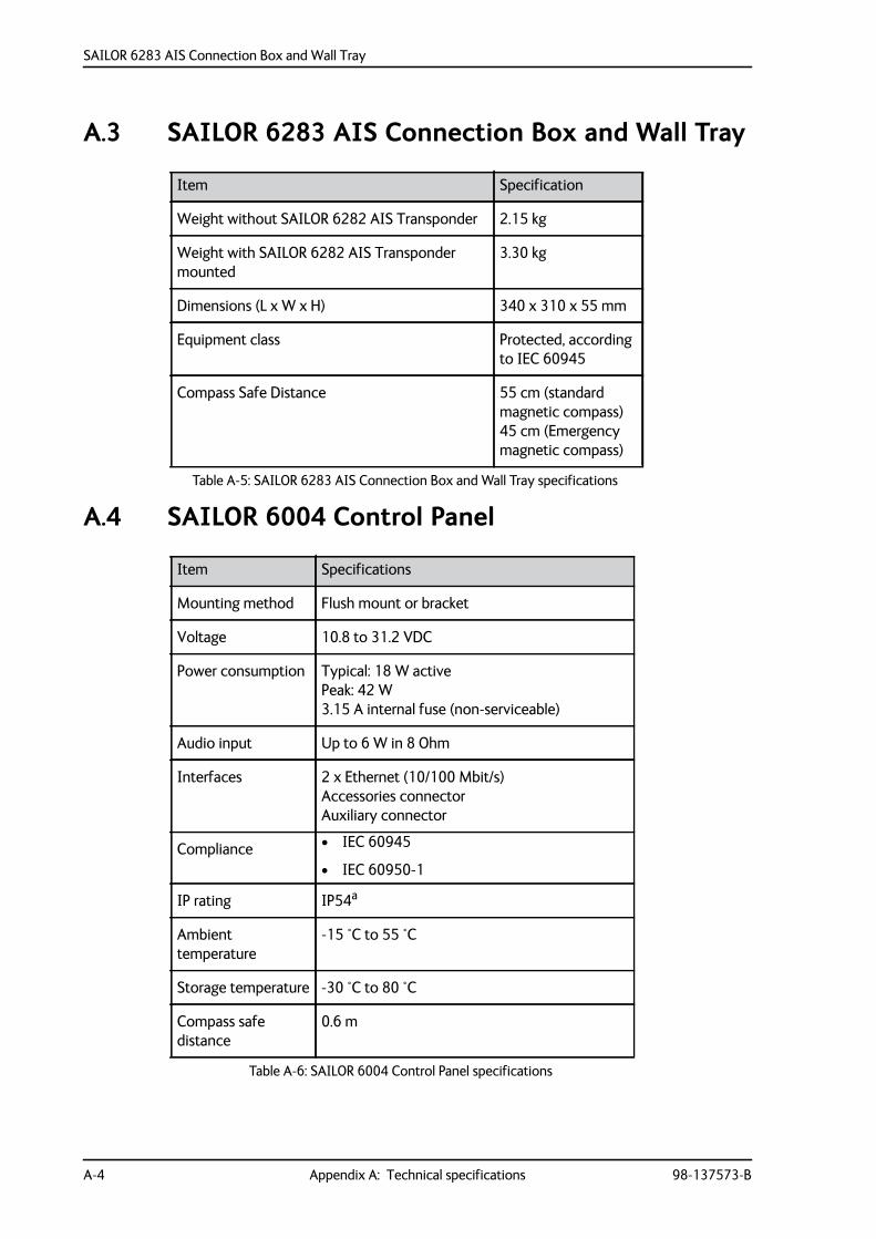
SAILOR 6283 AIS Connection Box and Wall Tray
A-4 Appendix A: Technical specifications 98-137573-B
A.3 SAILOR 6283 AIS Connection Box and Wall Tray
A.4 SAILOR 6004 Control Panel
Item Specification
Weight without SAILOR 6282 AIS Transponder 2.15 kg
Weight with SAILOR 6282 AIS Transponder mounted
3.30 kg
Dimensions (L x W x H) 340 x 310 x 55 mm
Equipment class Protected, according to IEC 60945
Compass Safe Distance 55 cm (standard magnetic compass) 45 cm (Emergency magnetic compass)
Table A-5: SAILOR 6283 AIS Connection Box and Wall Tray specifications
Item Specifications
Mounting method Flush mount or bracket
Voltage 10.8 to 31.2 VDC
Power consumption Typical: 18 W activePeak: 42 W3.15 A internal fuse (non-serviceable)
Audio input Up to 6 W in 8 Ohm
Interfaces 2 x Ethernet (10/100 Mbit/s)Accessories connectorAuxiliary connector
Compliance • IEC 60945
• IEC 60950-1
IP rating IP54a
Ambient temperature
-15 °C to 55 °C
Storage temperature -30 °C to 80 °C
Compass safe distance
0.6 m
Table A-6: SAILOR 6004 Control Panel specifications
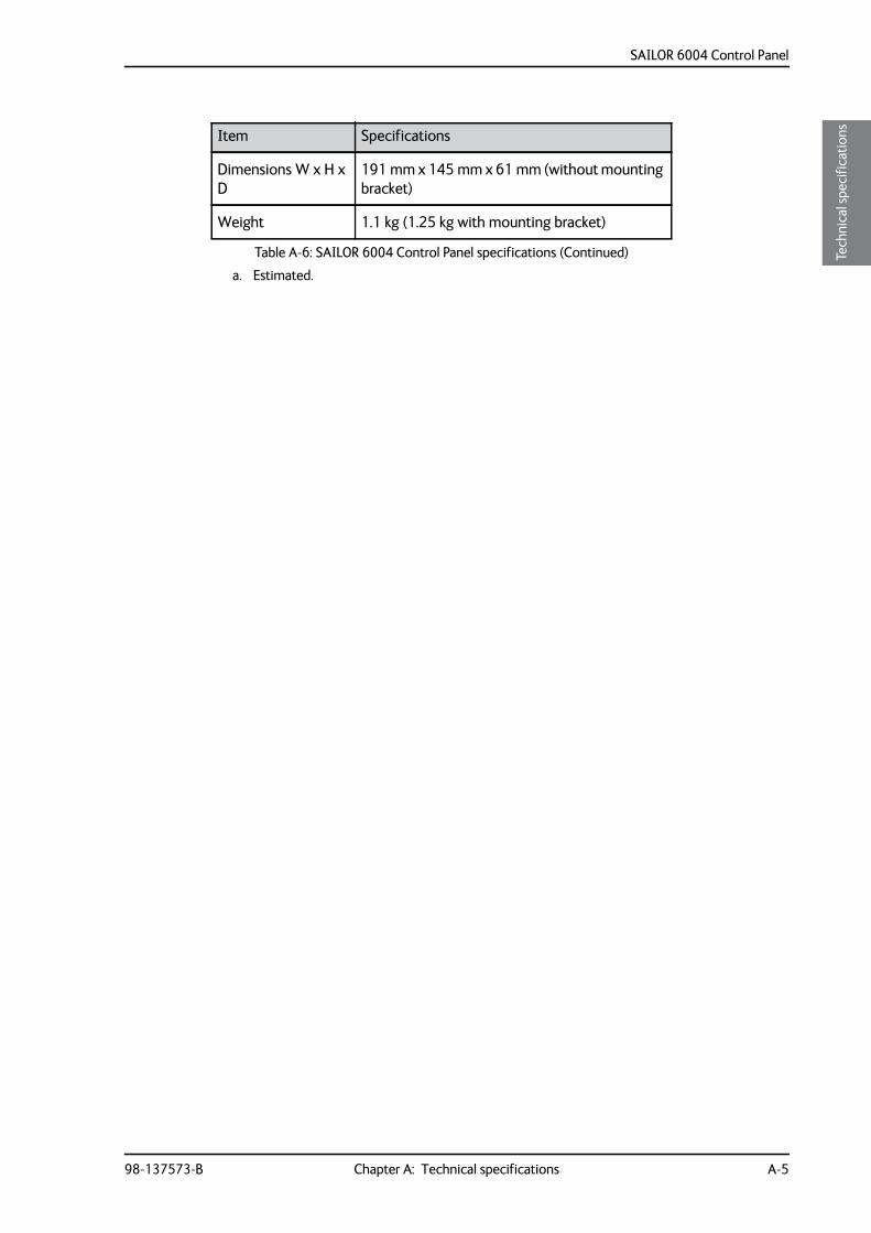
SAILOR 6004 Control Panel
98-137573-B Chapter A: Technical specifications A-5
AAAA
Tech
nica
l spe
cific
atio
ns
Dimensions W x H x D
191 mm x 145 mm x 61 mm (without mounting bracket)
Weight 1.1 kg (1.25 kg with mounting bracket)
a. Estimated.
Item Specifications
Table A-6: SAILOR 6004 Control Panel specifications (Continued)

SAILOR 6004 Control Panel
A-6 Chapter A: Technical specifications 98-137573-B
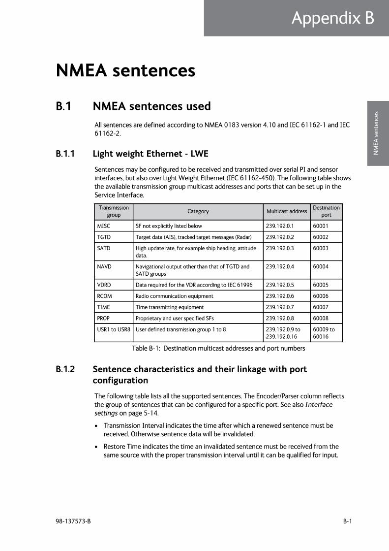
98-137573-B B-1
Appendix BBBBB
NM
EA se
nten
ces
NMEA sentences B
B.1 NMEA sentences usedAll sentences are defined according to NMEA 0183 version 4.10 and IEC 61162-1 and IEC 61162-2.
B.1.1 Light weight Ethernet - LWE
Sentences may be configured to be received and transmitted over serial PI and sensor interfaces, but also over Light Weight Ethernet (IEC 61162-450). The following table shows the available transmission group multicast addresses and ports that can be set up in the Service Interface.
B.1.2 Sentence characteristics and their linkage with port configuration
The following table lists all the supported sentences. The Encoder/Parser column reflects the group of sentences that can be configured for a specific port. See also Interface settings on page 5-14.
• Transmission Interval indicates the time after which a renewed sentence must be received. Otherwise sentence data will be invalidated.
• Restore Time indicates the time an invalidated sentence must be received from the same source with the proper transmission interval until it can be qualified for input.
Transmissiongroup
Category Multicast addressDestination
port
MISC SF not explicitly listed below 239.192.0.1 60001
TGTD Target data (AIS), tracked target messages (Radar) 239.192.0.2 60002
SATD High update rate, for example ship heading, attitude data.
239.192.0.3 60003
NAVD Navigational output other than that of TGTD and SATD groups
239.192.0.4 60004
VDRD Data required for the VDR according to IEC 61996 239.192.0.5 60005
RCOM Radio communication equipment 239.192.0.6 60006
TIME Time transmitting equipment 239.192.0.7 60007
PROP Proprietary and user specified SFs 239.192.0.8 60008
USR1 to USR8 User defined transmission group 1 to 8 239.192.0.9 to 239.192.0.16
60009 to 60016
Table B-1: Destination multicast addresses and port numbers
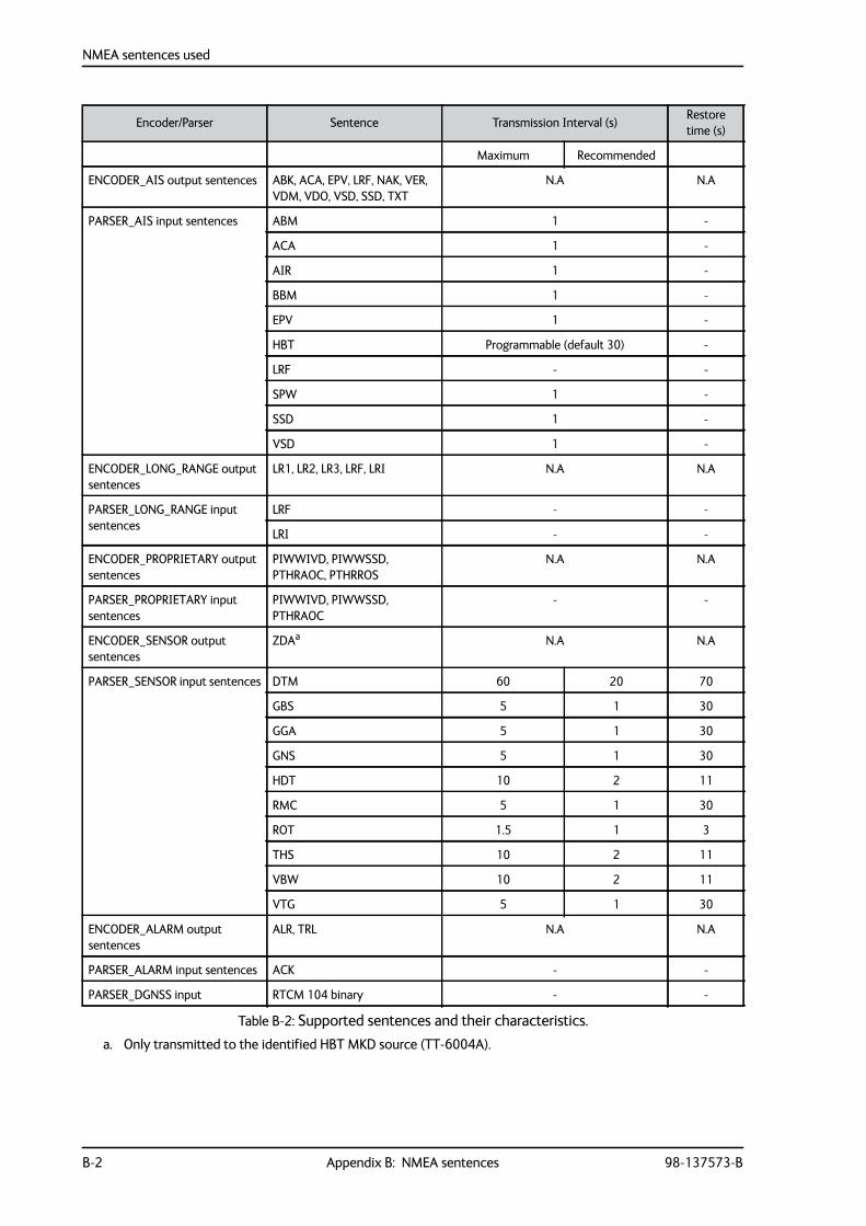
NMEA sentences used
B-2 Appendix B: NMEA sentences 98-137573-B
Encoder/Parser Sentence Transmission Interval (s)Restore time (s)
Maximum Recommended
ENCODER_AIS output sentences ABK, ACA, EPV, LRF, NAK, VER, VDM, VDO, VSD, SSD, TXT
N.A N.A
PARSER_AIS input sentences ABM 1 -
ACA 1 -
AIR 1 -
BBM 1 -
EPV 1 -
HBT Programmable (default 30) -
LRF - -
SPW 1 -
SSD 1 -
VSD 1 -
ENCODER_LONG_RANGE output sentences
LR1, LR2, LR3, LRF, LRI N.A N.A
PARSER_LONG_RANGE input sentences
LRF - -
LRI - -
ENCODER_PROPRIETARY output sentences
PIWWIVD, PIWWSSD, PTHRAOC, PTHRROS
N.A N.A
PARSER_PROPRIETARY input sentences
PIWWIVD, PIWWSSD, PTHRAOC
- -
ENCODER_SENSOR output sentences
ZDAa N.A N.A
PARSER_SENSOR input sentences DTM 60 20 70
GBS 5 1 30
GGA 5 1 30
GNS 5 1 30
HDT 10 2 11
RMC 5 1 30
ROT 1.5 1 3
THS 10 2 11
VBW 10 2 11
VTG 5 1 30
ENCODER_ALARM output sentences
ALR, TRL N.A N.A
PARSER_ALARM input sentences ACK - -
PARSER_DGNSS input RTCM 104 binary - -
Table B-2: Supported sentences and their characteristics.a. Only transmitted to the identified HBT MKD source (TT-6004A).
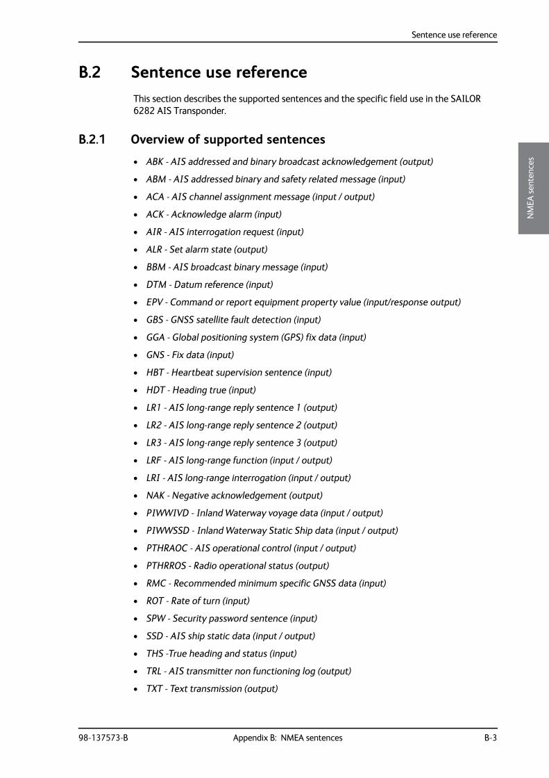
Sentence use reference
98-137573-B Appendix B: NMEA sentences B-3
BBBB
NM
EA se
nten
ces
B.2 Sentence use referenceThis section describes the supported sentences and the specific field use in the SAILOR 6282 AIS Transponder.
B.2.1 Overview of supported sentences
• ABK - AIS addressed and binary broadcast acknowledgement (output)
• ABM - AIS addressed binary and safety related message (input)
• ACA - AIS channel assignment message (input / output)
• ACK - Acknowledge alarm (input)
• AIR - AIS interrogation request (input)
• ALR - Set alarm state (output)
• BBM - AIS broadcast binary message (input)
• DTM - Datum reference (input)
• EPV - Command or report equipment property value (input/response output)
• GBS - GNSS satellite fault detection (input)
• GGA - Global positioning system (GPS) fix data (input)
• GNS - Fix data (input)
• HBT - Heartbeat supervision sentence (input)
• HDT - Heading true (input)
• LR1 - AIS long-range reply sentence 1 (output)
• LR2 - AIS long-range reply sentence 2 (output)
• LR3 - AIS long-range reply sentence 3 (output)
• LRF - AIS long-range function (input / output)
• LRI - AIS long-range interrogation (input / output)
• NAK - Negative acknowledgement (output)
• PIWWIVD - Inland Waterway voyage data (input / output)
• PIWWSSD - Inland Waterway Static Ship data (input / output)
• PTHRAOC - AIS operational control (input / output)
• PTHRROS - Radio operational status (output)
• RMC - Recommended minimum specific GNSS data (input)
• ROT - Rate of turn (input)
• SPW - Security password sentence (input)
• SSD - AIS ship static data (input / output)
• THS -True heading and status (input)
• TRL - AIS transmitter non functioning log (output)
• TXT - Text transmission (output)
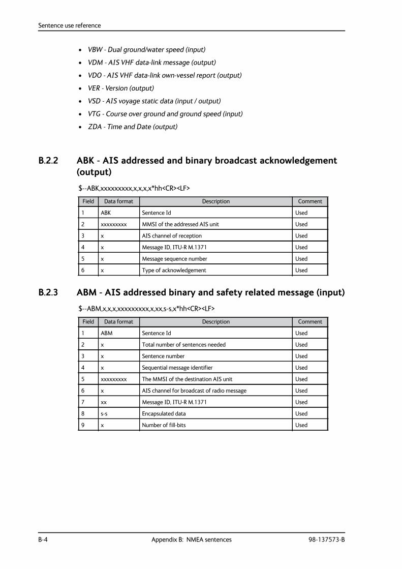
Sentence use reference
B-4 Appendix B: NMEA sentences 98-137573-B
• VBW - Dual ground/water speed (input)
• VDM - AIS VHF data-link message (output)
• VDO - AIS VHF data-link own-vessel report (output)
• VER - Version (output)
• VSD - AIS voyage static data (input / output)
• VTG - Course over ground and ground speed (input)
• ZDA - Time and Date (output)
B.2.2 ABK - AIS addressed and binary broadcast acknowledgement (output)
$--ABK,xxxxxxxxx,x,x,x,x*hh<CR><LF>
B.2.3 ABM - AIS addressed binary and safety related message (input)
$--ABM,x,x,x,xxxxxxxxx,x,xx,s-s,x*hh<CR><LF>
Field Data format Description Comment
1 ABK Sentence Id Used
2 xxxxxxxxx MMSI of the addressed AIS unit Used
3 x AIS channel of reception Used
4 x Message ID, ITU-R M.1371 Used
5 x Message sequence number Used
6 x Type of acknowledgement Used
Field Data format Description Comment
1 ABM Sentence Id Used
2 x Total number of sentences needed Used
3 x Sentence number Used
4 x Sequential message identifier Used
5 xxxxxxxxx The MMSI of the destination AIS unit Used
6 x AIS channel for broadcast of radio message Used
7 xx Message ID, ITU-R M.1371 Used
8 s-s Encapsulated data Used
9 x Number of fill-bits Used
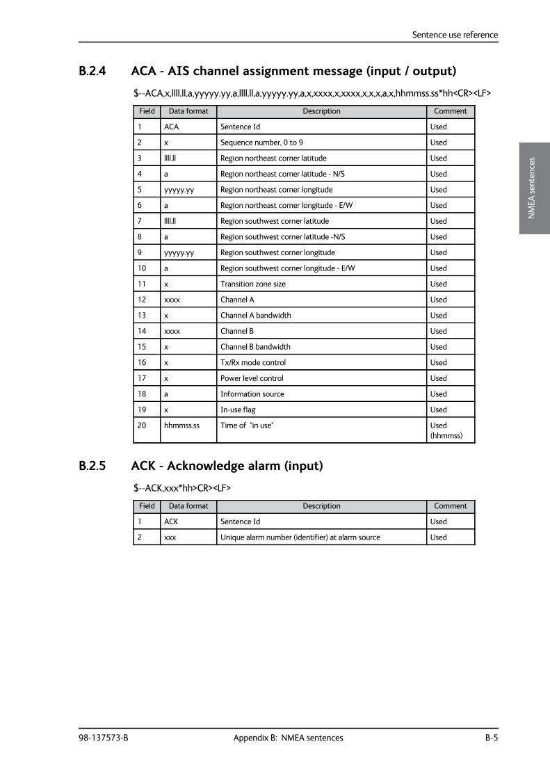
Sentence use reference
98-137573-B Appendix B: NMEA sentences B-5
BBBB
NM
EA se
nten
ces
B.2.4 ACA - AIS channel assignment message (input / output)
$--ACA,x,llll.ll,a,yyyyy.yy,a,llll.ll,a,yyyyy.yy,a,x,xxxx,x,xxxx,x,x,x,a,x,hhmmss.ss*hh<CR><LF>
B.2.5 ACK - Acknowledge alarm (input)
$--ACK,xxx*hh>CR><LF>
Field Data format Description Comment
1 ACA Sentence Id Used
2 x Sequence number, 0 to 9 Used
3 llll.ll Region northeast corner latitude Used
4 a Region northeast corner latitude - N/S Used
5 yyyyy.yy Region northeast corner longitude Used
6 a Region northeast corner longitude - E/W Used
7 llll.ll Region southwest corner latitude Used
8 a Region southwest corner latitude -N/S Used
9 yyyyy.yy Region southwest corner longitude Used
10 a Region southwest corner longitude - E/W Used
11 x Transition zone size Used
12 xxxx Channel A Used
13 x Channel A bandwidth Used
14 xxxx Channel B Used
15 x Channel B bandwidth Used
16 x Tx/Rx mode control Used
17 x Power level control Used
18 a Information source Used
19 x In-use flag Used
20 hhmmss.ss Time of "in use" Used (hhmmss)
Field Data format Description Comment
1 ACK Sentence Id Used
2 xxx Unique alarm number (identifier) at alarm source Used
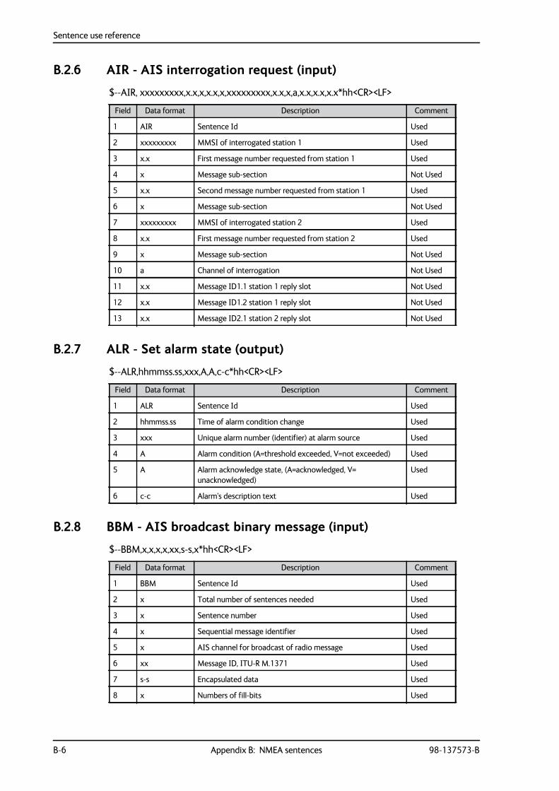
Sentence use reference
B-6 Appendix B: NMEA sentences 98-137573-B
B.2.6 AIR - AIS interrogation request (input)
$--AIR, xxxxxxxxx,x.x,x,x.x,x,xxxxxxxxx,x.x,x,a,x.x,x.x,x.x*hh<CR><LF>
B.2.7 ALR - Set alarm state (output)
$--ALR,hhmmss.ss,xxx,A,A,c-c*hh<CR><LF>
B.2.8 BBM - AIS broadcast binary message (input)
$--BBM,x,x,x,x,xx,s-s,x*hh<CR><LF>
Field Data format Description Comment
1 AIR Sentence Id Used
2 xxxxxxxxx MMSI of interrogated station 1 Used
3 x.x First message number requested from station 1 Used
4 x Message sub-section Not Used
5 x.x Second message number requested from station 1 Used
6 x Message sub-section Not Used
7 xxxxxxxxx MMSI of interrogated station 2 Used
8 x.x First message number requested from station 2 Used
9 x Message sub-section Not Used
10 a Channel of interrogation Not Used
11 x.x Message ID1.1 station 1 reply slot Not Used
12 x.x Message ID1.2 station 1 reply slot Not Used
13 x.x Message ID2.1 station 2 reply slot Not Used
Field Data format Description Comment
1 ALR Sentence Id Used
2 hhmmss.ss Time of alarm condition change Used
3 xxx Unique alarm number (identifier) at alarm source Used
4 A Alarm condition (A=threshold exceeded, V=not exceeded) Used
5 A Alarm acknowledge state, (A=acknowledged, V= unacknowledged)
Used
6 c-c Alarm's description text Used
Field Data format Description Comment
1 BBM Sentence Id Used
2 x Total number of sentences needed Used
3 x Sentence number Used
4 x Sequential message identifier Used
5 x AIS channel for broadcast of radio message Used
6 xx Message ID, ITU-R M.1371 Used
7 s-s Encapsulated data Used
8 x Numbers of fill-bits Used
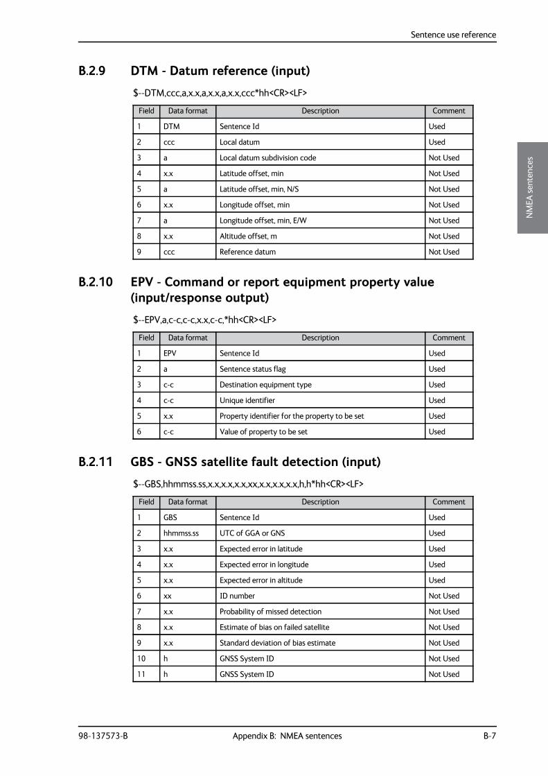
Sentence use reference
98-137573-B Appendix B: NMEA sentences B-7
BBBB
NM
EA se
nten
ces
B.2.9 DTM - Datum reference (input)
$--DTM,ccc,a,x.x,a,x.x,a,x.x,ccc*hh<CR><LF>
B.2.10 EPV - Command or report equipment property value (input/response output)
$--EPV,a,c-c,c-c,x.x,c-c,*hh<CR><LF>
B.2.11 GBS - GNSS satellite fault detection (input)
$--GBS,hhmmss.ss,x.x,x.x,x.x,xx,x.x,x.x,x.x,h,h*hh<CR><LF>
Field Data format Description Comment
1 DTM Sentence Id Used
2 ccc Local datum Used
3 a Local datum subdivision code Not Used
4 x.x Latitude offset, min Not Used
5 a Latitude offset, min, N/S Not Used
6 x.x Longitude offset, min Not Used
7 a Longitude offset, min, E/W Not Used
8 x.x Altitude offset, m Not Used
9 ccc Reference datum Not Used
Field Data format Description Comment
1 EPV Sentence Id Used
2 a Sentence status flag Used
3 c-c Destination equipment type Used
4 c-c Unique identifier Used
5 x.x Property identifier for the property to be set Used
6 c-c Value of property to be set Used
Field Data format Description Comment
1 GBS Sentence Id Used
2 hhmmss.ss UTC of GGA or GNS Used
3 x.x Expected error in latitude Used
4 x.x Expected error in longitude Used
5 x.x Expected error in altitude Used
6 xx ID number Not Used
7 x.x Probability of missed detection Not Used
8 x.x Estimate of bias on failed satellite Not Used
9 x.x Standard deviation of bias estimate Not Used
10 h GNSS System ID Not Used
11 h GNSS System ID Not Used
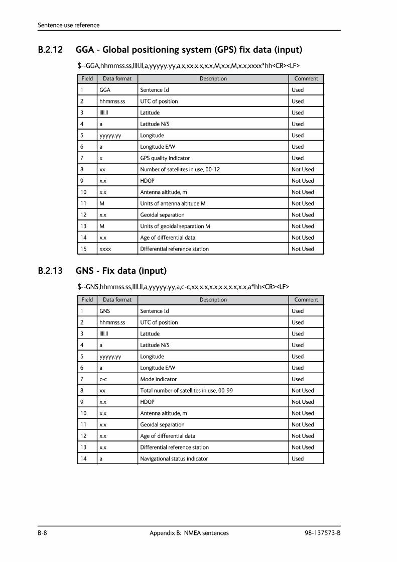
Sentence use reference
B-8 Appendix B: NMEA sentences 98-137573-B
B.2.12 GGA - Global positioning system (GPS) fix data (input)
$--GGA,hhmmss.ss,llll.ll,a,yyyyy.yy,a,x,xx,x.x,x.x,M,x.x,M,x.x,xxxx*hh<CR><LF>
B.2.13 GNS - Fix data (input)
$--GNS,hhmmss.ss,llll.ll,a,yyyyy.yy,a,c-c,xx,x.x,x.x,x.x,x.x,x.x,a*hh<CR><LF>
Field Data format Description Comment
1 GGA Sentence Id Used
2 hhmmss.ss UTC of position Used
3 llll.ll Latitude Used
4 a Latitude N/S Used
5 yyyyy.yy Longitude Used
6 a Longitude E/W Used
7 x GPS quality indicator Used
8 xx Number of satellites in use, 00-12 Not Used
9 x.x HDOP Not Used
10 x.x Antenna altitude, m Not Used
11 M Units of antenna altitude M Not Used
12 x.x Geoidal separation Not Used
13 M Units of geoidal separation M Not Used
14 x.x Age of differential data Not Used
15 xxxx Differential reference station Not Used
Field Data format Description Comment
1 GNS Sentence Id Used
2 hhmmss.ss UTC of position Used
3 llll.ll Latitude Used
4 a Latitude N/S Used
5 yyyyy.yy Longitude Used
6 a Longitude E/W Used
7 c-c Mode indicator Used
8 xx Total number of satellites in use, 00-99 Not Used
9 x.x HDOP Not Used
10 x.x Antenna altitude, m Not Used
11 x.x Geoidal separation Not Used
12 x.x Age of differential data Not Used
13 x.x Differential reference station Not Used
14 a Navigational status indicator Used
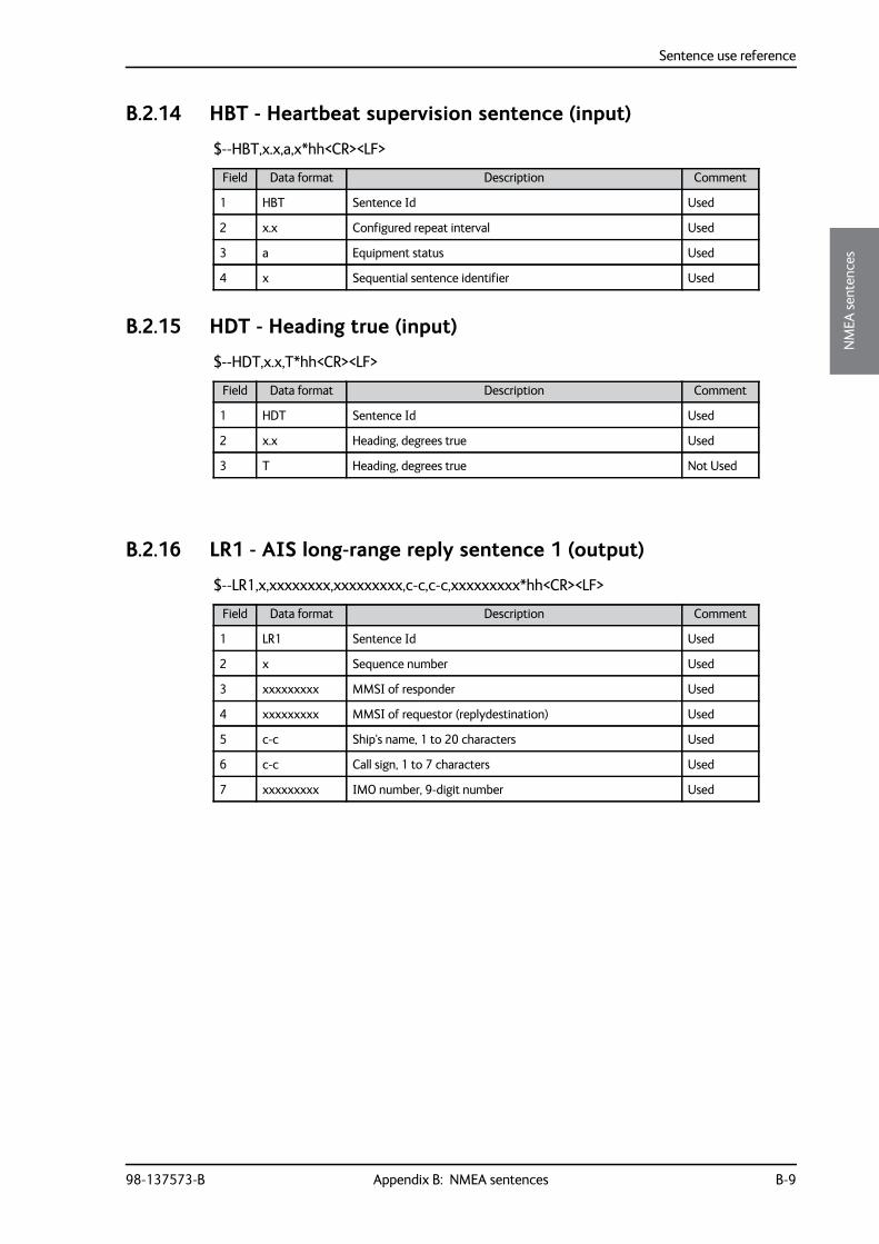
Sentence use reference
98-137573-B Appendix B: NMEA sentences B-9
BBBB
NM
EA se
nten
ces
B.2.14 HBT - Heartbeat supervision sentence (input)
$--HBT,x.x,a,x*hh<CR><LF>
B.2.15 HDT - Heading true (input)
$--HDT,x.x,T*hh<CR><LF>
B.2.16 LR1 - AIS long-range reply sentence 1 (output)
$--LR1,x,xxxxxxxx,xxxxxxxxx,c-c,c-c,xxxxxxxxx*hh<CR><LF>
Field Data format Description Comment
1 HBT Sentence Id Used
2 x.x Configured repeat interval Used
3 a Equipment status Used
4 x Sequential sentence identifier Used
Field Data format Description Comment
1 HDT Sentence Id Used
2 x.x Heading, degrees true Used
3 T Heading, degrees true Not Used
Field Data format Description Comment
1 LR1 Sentence Id Used
2 x Sequence number Used
3 xxxxxxxxx MMSI of responder Used
4 xxxxxxxxx MMSI of requestor (replydestination) Used
5 c-c Ship's name, 1 to 20 characters Used
6 c-c Call sign, 1 to 7 characters Used
7 xxxxxxxxx IMO number, 9-digit number Used
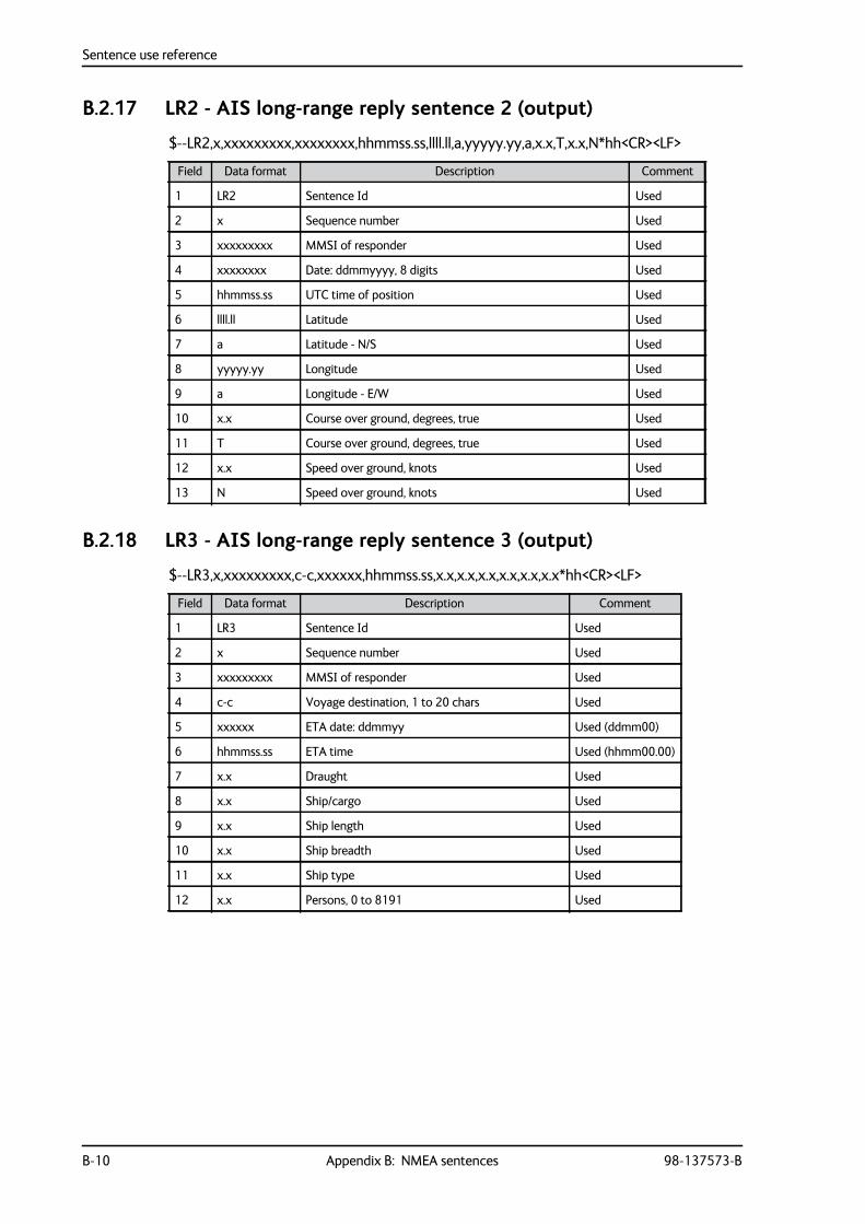
Sentence use reference
B-10 Appendix B: NMEA sentences 98-137573-B
B.2.17 LR2 - AIS long-range reply sentence 2 (output)
$--LR2,x,xxxxxxxxx,xxxxxxxx,hhmmss.ss,llll.ll,a,yyyyy.yy,a,x.x,T,x.x,N*hh<CR><LF>
B.2.18 LR3 - AIS long-range reply sentence 3 (output)
$--LR3,x,xxxxxxxxx,c-c,xxxxxx,hhmmss.ss,x.x,x.x,x.x,x.x,x.x,x.x*hh<CR><LF>
Field Data format Description Comment
1 LR2 Sentence Id Used
2 x Sequence number Used
3 xxxxxxxxx MMSI of responder Used
4 xxxxxxxx Date: ddmmyyyy, 8 digits Used
5 hhmmss.ss UTC time of position Used
6 llll.ll Latitude Used
7 a Latitude - N/S Used
8 yyyyy.yy Longitude Used
9 a Longitude - E/W Used
10 x.x Course over ground, degrees, true Used
11 T Course over ground, degrees, true Used
12 x.x Speed over ground, knots Used
13 N Speed over ground, knots Used
Field Data format Description Comment
1 LR3 Sentence Id Used
2 x Sequence number Used
3 xxxxxxxxx MMSI of responder Used
4 c-c Voyage destination, 1 to 20 chars Used
5 xxxxxx ETA date: ddmmyy Used (ddmm00)
6 hhmmss.ss ETA time Used (hhmm00.00)
7 x.x Draught Used
8 x.x Ship/cargo Used
9 x.x Ship length Used
10 x.x Ship breadth Used
11 x.x Ship type Used
12 x.x Persons, 0 to 8191 Used
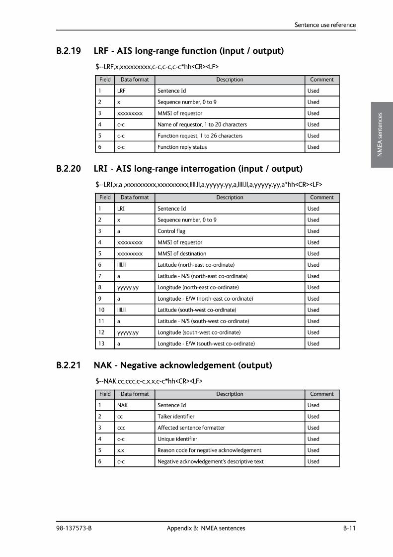
Sentence use reference
98-137573-B Appendix B: NMEA sentences B-11
BBBB
NM
EA se
nten
ces
B.2.19 LRF - AIS long-range function (input / output)
$--LRF,x,xxxxxxxxx,c-c,c-c,c-c*hh<CR><LF>
B.2.20 LRI - AIS long-range interrogation (input / output)
$--LRI,x,a ,xxxxxxxxx,xxxxxxxxx,llll.ll,a,yyyyy.yy,a,llll.ll,a,yyyyy.yy,a*hh<CR><LF>
B.2.21 NAK - Negative acknowledgement (output)
$--NAK,cc,ccc,c-c,x.x,c-c*hh<CR><LF>
Field Data format Description Comment
1 LRF Sentence Id Used
2 x Sequence number, 0 to 9 Used
3 xxxxxxxxx MMSI of requestor Used
4 c-c Name of requestor, 1 to 20 characters Used
5 c-c Function request, 1 to 26 characters Used
6 c-c Function reply status Used
Field Data format Description Comment
1 LRI Sentence Id Used
2 x Sequence number, 0 to 9 Used
3 a Control flag Used
4 xxxxxxxxx MMSI of requestor Used
5 xxxxxxxxx MMSI of destination Used
6 llll.ll Latitude (north-east co-ordinate) Used
7 a Latitude - N/S (north-east co-ordinate) Used
8 yyyyy.yy Longitude (north-east co-ordinate) Used
9 a Longitude - E/W (north-east co-ordinate) Used
10 llll.ll Latitude (south-west co-ordinate) Used
11 a Latitude - N/S (south-west co-ordinate) Used
12 yyyyy.yy Longitude (south-west co-ordinate) Used
13 a Longitude - E/W (south-west co-ordinate) Used
Field Data format Description Comment
1 NAK Sentence Id Used
2 cc Talker identifier Used
3 ccc Affected sentence formatter Used
4 c-c Unique identifier Used
5 x.x Reason code for negative acknowledgement Used
6 c-c Negative acknowledgement's descriptive text Used
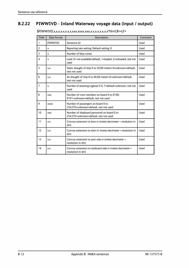
Sentence use reference
B-12 Appendix B: NMEA sentences 98-137573-B
B.2.22 PIWWIVD - Inland Waterway voyage data (input / output)
$PIWWIVD,x,x,x,x.x,x.x,x,xxx,xxxx,xxx,x.x,x.x,x.x,x.x*hh<CR><LF>
Field Data format Description Comment
1 PIWWIVD Sentence Id Used
2 x Reporting rate setting. Default setting: 0 Used
3 x Number of blue cones Used
4 x Load. 0= not available=default, 1=loaded, 2=unloaded, rest not used
Used
5 x.x Static draught of ship 0 to 20,00 meters 0=unknown=default, rest not used
Used
6 x.x Air draught of ship 0 to 40,00 meters 0=unknown=default, rest not used
Used
7 x Number of assisting tugboat 0-6, 7=default=unknown, rest not used
Used
8 xxx Number of crew members on board 0 to 8190, 8191=unknown=default, rest not used
Used
9 xxxx Number of passengers on board 0 to 254,255=unknown=default, rest not used
Used
10 xxx Number of shipboard personnel on board 0 to 254,255=unknown=default, rest not used
Used
11 x.x Convoy extension to bow in (meter.decimeter = resolution in dm)
Used
12 x.x Convoy extension to stern in (meter.decimeter = resolution in dm)
Used
13 x.x Convoy extension to port side in (meter.decimeter = resolution in dm)
Used
14 x.x Convoy extension to starboard side in (meter.decimeter = resolution in dm)
Used
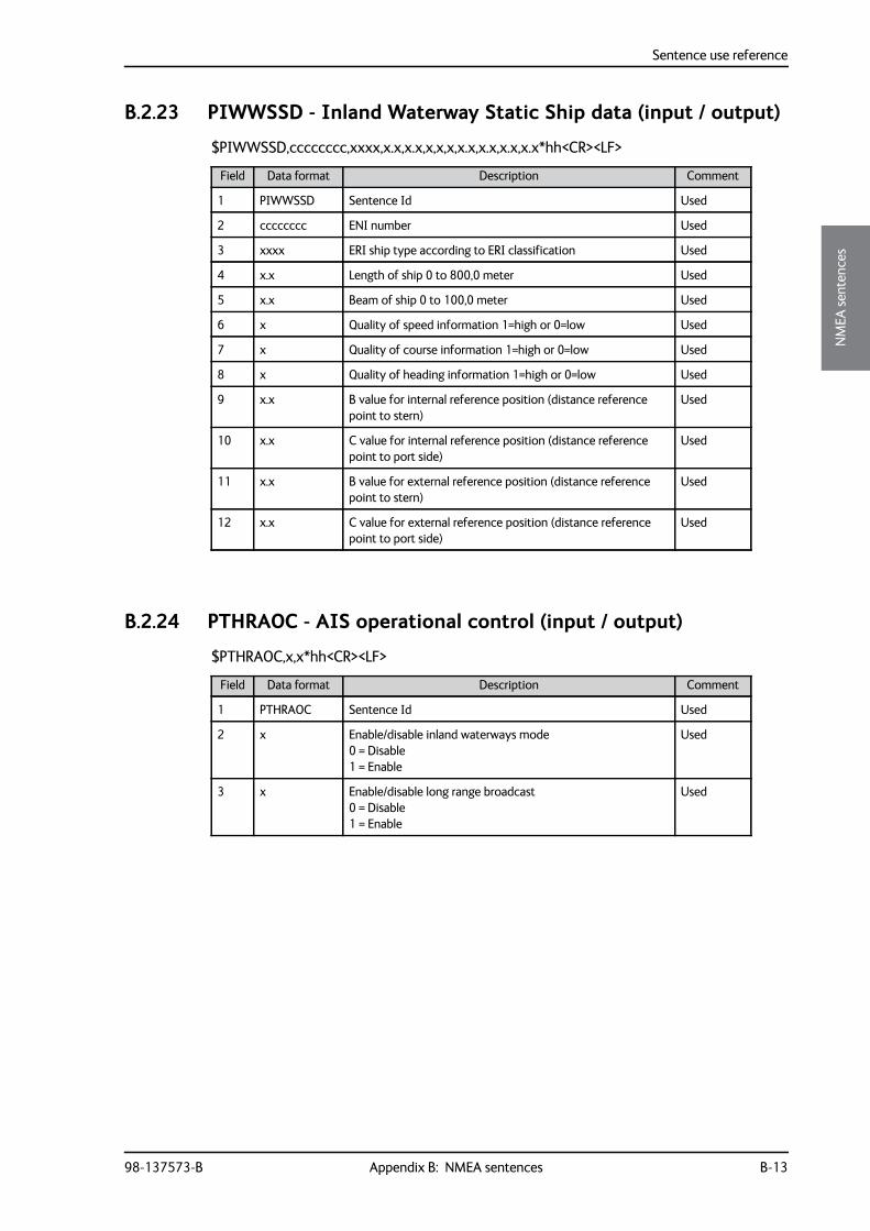
Sentence use reference
98-137573-B Appendix B: NMEA sentences B-13
BBBB
NM
EA se
nten
ces
B.2.23 PIWWSSD - Inland Waterway Static Ship data (input / output)
$PIWWSSD,cccccccc,xxxx,x.x,x.x,x,x,x,x.x,x.x,x.x,x.x*hh<CR><LF>
B.2.24 PTHRAOC - AIS operational control (input / output)
$PTHRAOC,x,x*hh<CR><LF>
Field Data format Description Comment
1 PIWWSSD Sentence Id Used
2 cccccccc ENI number Used
3 xxxx ERI ship type according to ERI classification Used
4 x.x Length of ship 0 to 800,0 meter Used
5 x.x Beam of ship 0 to 100,0 meter Used
6 x Quality of speed information 1=high or 0=low Used
7 x Quality of course information 1=high or 0=low Used
8 x Quality of heading information 1=high or 0=low Used
9 x.x B value for internal reference position (distance reference point to stern)
Used
10 x.x C value for internal reference position (distance reference point to port side)
Used
11 x.x B value for external reference position (distance reference point to stern)
Used
12 x.x C value for external reference position (distance reference point to port side)
Used
Field Data format Description Comment
1 PTHRAOC Sentence Id Used
2 x Enable/disable inland waterways mode 0 = Disable 1 = Enable
Used
3 x Enable/disable long range broadcast 0 = Disable 1 = Enable
Used
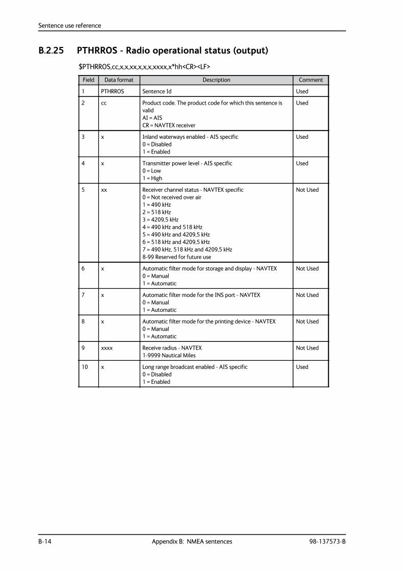
Sentence use reference
B-14 Appendix B: NMEA sentences 98-137573-B
B.2.25 PTHRROS - Radio operational status (output)
$PTHRROS,cc,x,x,xx,x,x,x,xxxx,x*hh<CR><LF>
Field Data format Description Comment
1 PTHRROS Sentence Id Used
2 cc Product code. The product code for which this sentence is valid AI = AIS CR = NAVTEX receiver
Used
3 x Inland waterways enabled - AIS specific 0 = Disabled 1 = Enabled
Used
4 x Transmitter power level - AIS specific 0 = Low 1 = High
Used
5 xx Receiver channel status - NAVTEX specific 0 = Not received over air 1 = 490 kHz 2 = 518 kHz 3 = 4209,5 kHz 4 = 490 kHz and 518 kHz 5 = 490 kHz and 4209,5 kHz 6 = 518 kHz and 4209,5 kHz 7 = 490 kHz, 518 kHz and 4209,5 kHz 8-99 Reserved for future use
Not Used
6 x Automatic filter mode for storage and display - NAVTEX 0 = Manual 1 = Automatic
Not Used
7 x Automatic filter mode for the INS port - NAVTEX 0 = Manual 1 = Automatic
Not Used
8 x Automatic filter mode for the printing device - NAVTEX 0 = Manual 1 = Automatic
Not Used
9 xxxx Receive radius - NAVTEX 1-9999 Nautical Miles
Not Used
10 x Long range broadcast enabled - AIS specific 0 = Disabled 1 = Enabled
Used
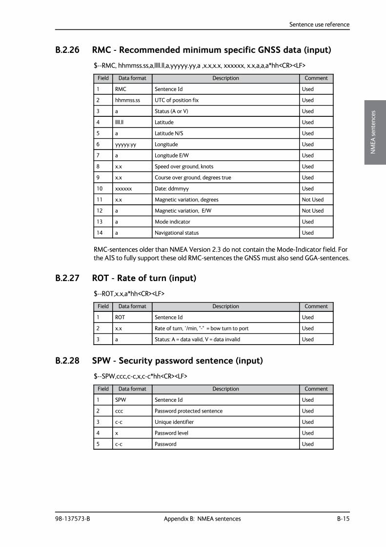
Sentence use reference
98-137573-B Appendix B: NMEA sentences B-15
BBBB
NM
EA se
nten
ces
B.2.26 RMC - Recommended minimum specific GNSS data (input)
$--RMC, hhmmss.ss,a,llll.ll,a,yyyyy.yy,a ,x.x,x.x, xxxxxx, x.x,a,a,a*hh<CR><LF>
RMC-sentences older than NMEA Version 2.3 do not contain the Mode-Indicator field. For the AIS to fully support these old RMC-sentences the GNSS must also send GGA-sentences.
B.2.27 ROT - Rate of turn (input)
$--ROT,x.x,a*hh<CR><LF>
B.2.28 SPW - Security password sentence (input)
$--SPW,ccc,c-c,x,c-c*hh<CR><LF>
Field Data format Description Comment
1 RMC Sentence Id Used
2 hhmmss.ss UTC of position fix Used
3 a Status (A or V) Used
4 llll.ll Latitude Used
5 a Latitude N/S Used
6 yyyyy.yy Longitude Used
7 a Longitude E/W Used
8 x.x Speed over ground, knots Used
9 x.x Course over ground, degrees true Used
10 xxxxxx Date: ddmmyy Used
11 x.x Magnetic variation, degrees Not Used
12 a Magnetic variation, E/W Not Used
13 a Mode indicator Used
14 a Navigational status Used
Field Data format Description Comment
1 ROT Sentence Id Used
2 x.x Rate of turn, °/min, "-" = bow turn to port Used
3 a Status: A = data valid, V = data invalid Used
Field Data format Description Comment
1 SPW Sentence Id Used
2 ccc Password protected sentence Used
3 c-c Unique identifier Used
4 x Password level Used
5 c-c Password Used
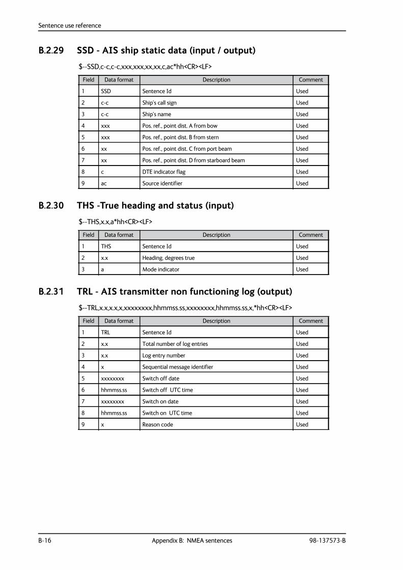
Sentence use reference
B-16 Appendix B: NMEA sentences 98-137573-B
B.2.29 SSD - AIS ship static data (input / output)
$--SSD,c-c,c-c,xxx,xxx,xx,xx,c,ac*hh<CR><LF>
B.2.30 THS -True heading and status (input)
$--THS,x.x,a*hh<CR><LF>
B.2.31 TRL - AIS transmitter non functioning log (output)
$--TRL,x.x,x.x,x,xxxxxxxx,hhmmss.ss,xxxxxxxx,hhmmss.ss,x,*hh<CR><LF>
Field Data format Description Comment
1 SSD Sentence Id Used
2 c-c Ship’s call sign Used
3 c-c Ship’s name Used
4 xxx Pos. ref., point dist. A from bow Used
5 xxx Pos. ref., point dist. B from stern Used
6 xx Pos. ref., point dist. C from port beam Used
7 xx Pos. ref., point dist. D from starboard beam Used
8 c DTE indicator flag Used
9 ac Source identifier Used
Field Data format Description Comment
1 THS Sentence Id Used
2 x.x Heading, degrees true Used
3 a Mode indicator Used
Field Data format Description Comment
1 TRL Sentence Id Used
2 x.x Total number of log entries Used
3 x.x Log entry number Used
4 x Sequential message identifier Used
5 xxxxxxxx Switch off date Used
6 hhmmss.ss Switch off UTC time Used
7 xxxxxxxx Switch on date Used
8 hhmmss.ss Switch on UTC time Used
9 x Reason code Used
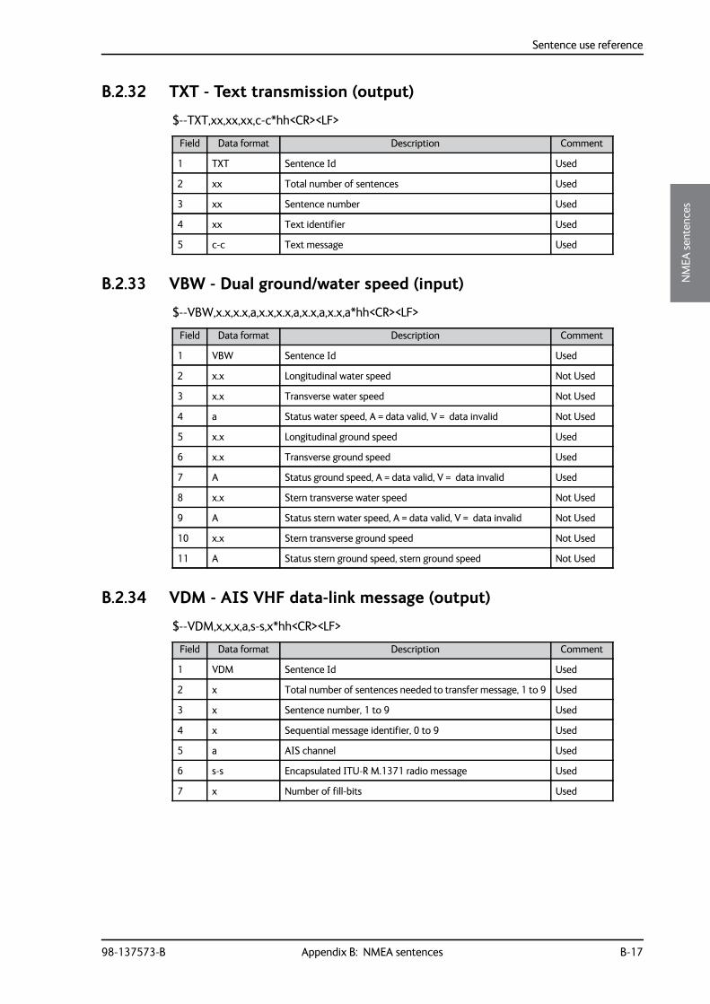
Sentence use reference
98-137573-B Appendix B: NMEA sentences B-17
BBBB
NM
EA se
nten
ces
B.2.32 TXT - Text transmission (output)
$--TXT,xx,xx,xx,c-c*hh<CR><LF>
B.2.33 VBW - Dual ground/water speed (input)
$--VBW,x.x,x.x,a,x.x,x.x,a,x.x,a,x.x,a*hh<CR><LF>
B.2.34 VDM - AIS VHF data-link message (output)
$--VDM,x,x,x,a,s-s,x*hh<CR><LF>
Field Data format Description Comment
1 TXT Sentence Id Used
2 xx Total number of sentences Used
3 xx Sentence number Used
4 xx Text identifier Used
5 c-c Text message Used
Field Data format Description Comment
1 VBW Sentence Id Used
2 x.x Longitudinal water speed Not Used
3 x.x Transverse water speed Not Used
4 a Status water speed, A = data valid, V = data invalid Not Used
5 x.x Longitudinal ground speed Used
6 x.x Transverse ground speed Used
7 A Status ground speed, A = data valid, V = data invalid Used
8 x.x Stern transverse water speed Not Used
9 A Status stern water speed, A = data valid, V = data invalid Not Used
10 x.x Stern transverse ground speed Not Used
11 A Status stern ground speed, stern ground speed Not Used
Field Data format Description Comment
1 VDM Sentence Id Used
2 x Total number of sentences needed to transfer message, 1 to 9 Used
3 x Sentence number, 1 to 9 Used
4 x Sequential message identifier, 0 to 9 Used
5 a AIS channel Used
6 s-s Encapsulated ITU-R M.1371 radio message Used
7 x Number of fill-bits Used
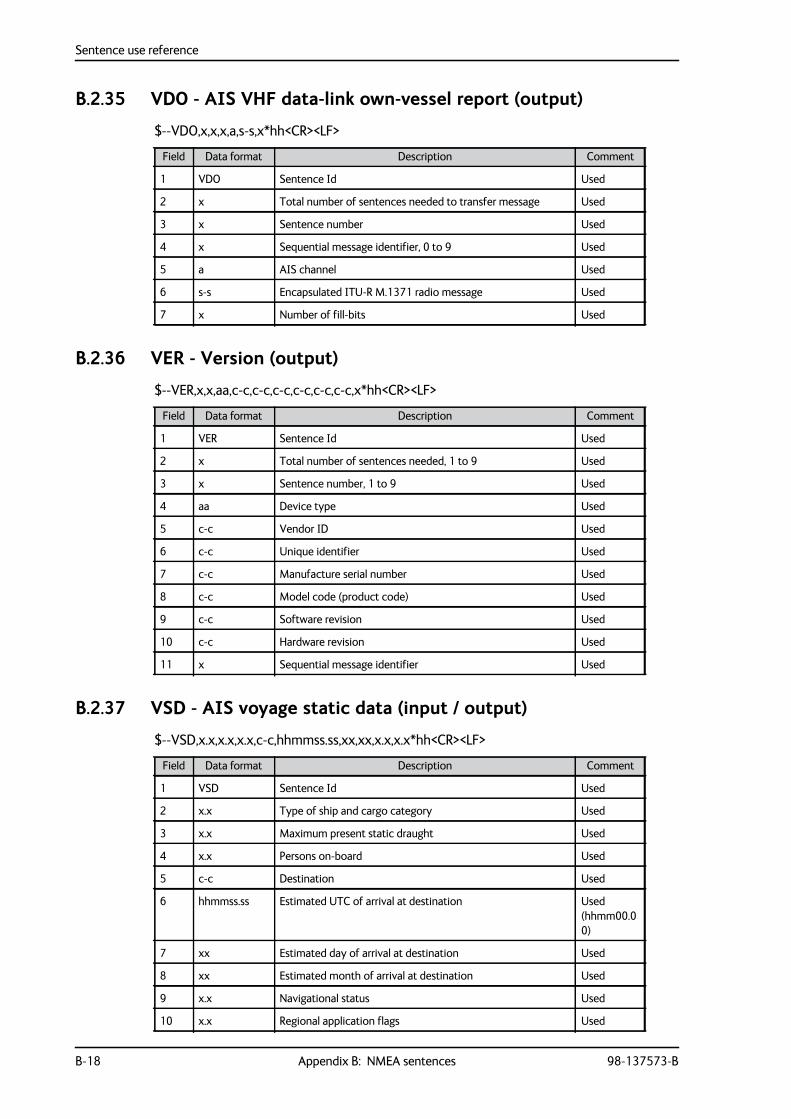
Sentence use reference
B-18 Appendix B: NMEA sentences 98-137573-B
B.2.35 VDO - AIS VHF data-link own-vessel report (output)
$--VDO,x,x,x,a,s-s,x*hh<CR><LF>
B.2.36 VER - Version (output)
$--VER,x,x,aa,c-c,c-c,c-c,c-c,c-c,c-c,x*hh<CR><LF>
B.2.37 VSD - AIS voyage static data (input / output)
$--VSD,x.x,x.x,x.x,c-c,hhmmss.ss,xx,xx,x.x,x.x*hh<CR><LF>
Field Data format Description Comment
1 VDO Sentence Id Used
2 x Total number of sentences needed to transfer message Used
3 x Sentence number Used
4 x Sequential message identifier, 0 to 9 Used
5 a AIS channel Used
6 s-s Encapsulated ITU-R M.1371 radio message Used
7 x Number of fill-bits Used
Field Data format Description Comment
1 VER Sentence Id Used
2 x Total number of sentences needed, 1 to 9 Used
3 x Sentence number, 1 to 9 Used
4 aa Device type Used
5 c-c Vendor ID Used
6 c-c Unique identifier Used
7 c-c Manufacture serial number Used
8 c-c Model code (product code) Used
9 c-c Software revision Used
10 c-c Hardware revision Used
11 x Sequential message identifier Used
Field Data format Description Comment
1 VSD Sentence Id Used
2 x.x Type of ship and cargo category Used
3 x.x Maximum present static draught Used
4 x.x Persons on-board Used
5 c-c Destination Used
6 hhmmss.ss Estimated UTC of arrival at destination Used (hhmm00.00)
7 xx Estimated day of arrival at destination Used
8 xx Estimated month of arrival at destination Used
9 x.x Navigational status Used
10 x.x Regional application flags Used
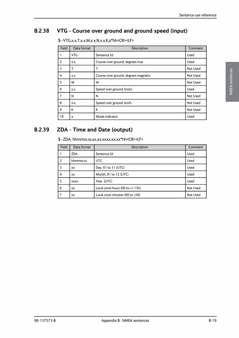
Sentence use reference
98-137573-B Appendix B: NMEA sentences B-19
BBBB
NM
EA se
nten
ces
B.2.38 VTG - Course over ground and ground speed (input)
$--VTG,x.x,T,x.x,M,x.x,N,x.x,K,a*hh<CR><LF>
B.2.39 ZDA - Time and Date (output)
$--ZDA, hhmmss.ss,xx,xx,xxxx,xx,xx*hh<CR><LF>
Field Data format Description Comment
1 VTG Sentence Id Used
2 x.x Course over ground, degrees true Used
3 T T Not Used
4 x.x Course over ground, degrees magnetic Not Used
5 M M Not Used
6 x.x Speed over ground, knots Used
7 N N Not Used
8 x.x Speed over ground, km/h Not Used
9 K K Not Used
10 a Mode indicator Used
Field Data format Description Comment
1 ZDA Sentence Id Used
2 hhmmss.ss UTC Used
3 xx Day, 01 to 31 (UTC) Used
4 xx Month, 01 to 12 (UTC) Used
5 xxxx Year (UTC) Used
6 xx Local zone hours (00 to +/-13h) Not Used
7 xx Local zone minutes (00 to +59) Not Used

Sentence use reference
B-20 Appendix B: NMEA sentences 98-137573-B
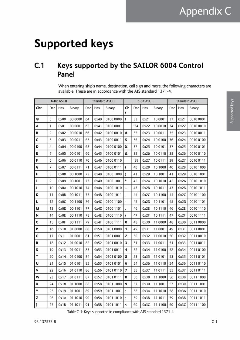
98-137573-B C-1
Appendix CCCCC
Supp
orte
d ke
ys
Supported keys C
C.1 Keys supported by the SAILOR 6004 Control PanelWhen entering ship’s name, destination, call sign and more, the following characters are available. These are in accordance with the AIS standard 1371-4.
6-Bit ASCII Standard ASCII 6-Bit ASCII Standard ASCII
Chr Dec Hex Binary Dec Hex Binary Chr
Dec Hex Binary Dec Hex Binary
@ 0 0x00 00 0000 64 0x40 0100 0000 ! 33 0x21 10 0001 33 0x21 0010 0001
A 1 0x01 00 0001 65 0x41 0100 0001 "34 0x22 10 0010 34 0x22 0010 0010
B 2 0x02 00 0010 66 0x42 0100 0010 # 35 0x23 10 0011 35 0x23 0010 0011
C 3 0x03 00 0011 67 0x43 0100 0011 $ 36 0x24 10 0100 36 0x24 0010 0100
D 4 0x04 00 0100 68 0x44 0100 0100 % 37 0x25 10 0101 37 0x25 0010 0101
E 5 0x05 00 0101 69 0x45 0100 0101 & 38 0x26 10 0110 38 0x26 0010 0110
F 6 0x06 00 0110 70 0x46 0100 0110 `39 0x27 10 0111 39 0x27 0010 0111
G 7 0x07 00 0111 71 0x47 0100 0111 ( 40 0x28 10 1000 40 0x28 0010 1000
H 8 0x08 00 1000 72 0x48 0100 1000 ) 41 0x29 10 1001 41 0x29 0010 1001
I 9 0x09 00 1001 73 0x49 0100 1001 * 42 0x2A 10 1010 42 0x2A 0010 1010
J 10 0x0A 00 1010 74 0x4A 0100 1010 + 43 0x2B 10 1011 43 0x2B 0010 1011
K 11 0x0B 00 1011 75 0x4B 0100 1011 , 44 0x2C 10 1100 44 0x2C 0010 1100
L 12 0x0C 00 1100 76 0x4C 0100 1100 - 45 0x2D 10 1101 45 0x2D 0010 1101
M 13 0x0D 00 1101 77 0x4D 0100 1101 . 46 0x2E 10 1110 46 0x2E 0010 1110
N 14 0x0E 00 1110 78 0x4E 0100 1110 / 47 0x2F 10 1111 47 0x2F 0010 1111
O 15 0x0F 00 1111 79 0x4F 0100 1111 0 48 0x30 11 0000 48 0x30 0011 0000
P 16 0x10 01 0000 80 0x50 0101 0000 1 49 0x31 11 0001 49 0x31 0011 0001
Q 17 0x11 01 0001 81 0x51 0101 0001 2 50 0x32 11 0010 50 0x32 0011 0010
R 18 0x12 01 0010 82 0x52 0101 0010 3 51 0x33 11 0011 51 0x33 0011 0011
S 19 0x13 01 0011 83 0x53 0101 0011 4 52 0x34 11 0100 52 0x34 0011 0100
T 20 0x14 01 0100 84 0x54 0101 0100 5 53 0x35 11 0101 53 0x35 0011 0101
U 21 0x15 01 0101 85 0x55 0101 0101 6 54 0x36 11 0110 54 0x36 0011 0110
V 22 0x16 01 0110 86 0x56 0101 0110 7 55 0x37 11 0111 55 0x37 0011 0111
W 23 0x17 01 0111 87 0x57 0101 0111 8 56 0x38 11 1000 56 0x38 0011 1000
X 24 0x18 01 1000 88 0x58 0101 1000 9 57 0x39 11 1001 57 0x39 0011 1001
Y 25 0x19 01 1001 89 0x59 0101 1001 : 58 0x3A 11 1010 58 0x3A 0011 1010
Z 26 0x1A 01 1010 90 0x5A 0101 1010 ; 59 0x3B 11 1011 59 0x3B 0011 1011
[ 27 0x1B 01 1011 91 0x5B 0101 1011 < 60 0x3C 11 1100 60 0x3C 0011 1100
Table C-1: Keys supported in compliance with AIS standard 1371-4

Keys supported by the SAILOR 6004 Control Panel
C-2 Appendix C: Supported keys 98-137573-B
\ 28 0x1C 01 1100 92 0x5C 0101 1100 = 61 0x3D 11 1101 61 0x3D 0011 1101
] 29 0x1D 01 1101 93 0x5D 0101 1101 > 62 0x3E 11 1110 62 0x3E 0011 1110
^ 30 0x1E 01 1110 94 0x5E 0101 1110 ? 63 0x3F 11 1111 63 0x3F 0011 1111
- 31 0x1F 01 1111 95 0x5F 0101 1111
Space 32 0x20 10 0000 32 0x20 0010 0000
6-Bit ASCII Standard ASCII 6-Bit ASCII Standard ASCII
Table C-1: Keys supported in compliance with AIS standard 1371-4 (Continued)
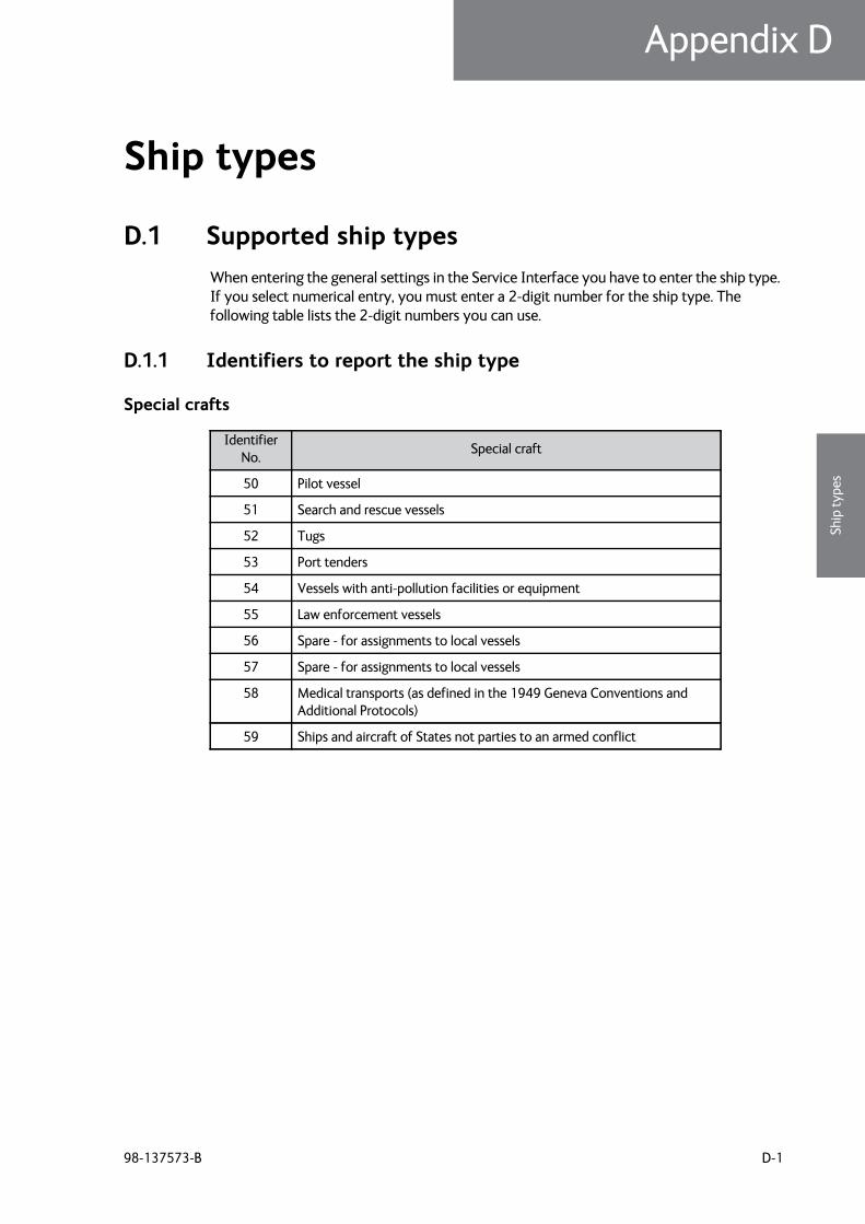
98-137573-B D-1
Appendix DDDDD
Ship
type
s
Ship types D
D.1 Supported ship typesWhen entering the general settings in the Service Interface you have to enter the ship type. If you select numerical entry, you must enter a 2-digit number for the ship type. The following table lists the 2-digit numbers you can use.
D.1.1 Identifiers to report the ship type
Special crafts
Identifier No. Special craft
50 Pilot vessel
51 Search and rescue vessels
52 Tugs
53 Port tenders
54 Vessels with anti-pollution facilities or equipment
55 Law enforcement vessels
56 Spare - for assignments to local vessels
57 Spare - for assignments to local vessels
58 Medical transports (as defined in the 1949 Geneva Conventions and Additional Protocols)
59 Ships and aircraft of States not parties to an armed conflict
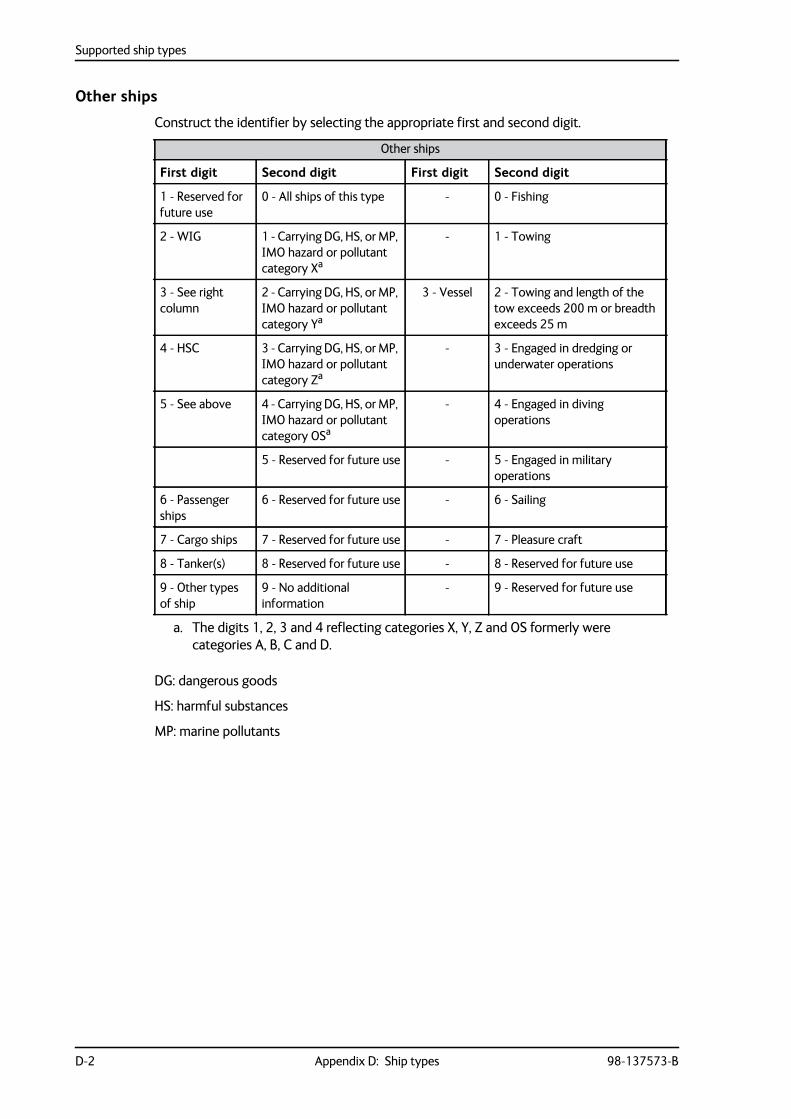
Supported ship types
D-2 Appendix D: Ship types 98-137573-B
Other ships
Construct the identifier by selecting the appropriate first and second digit.
DG: dangerous goods
HS: harmful substances
MP: marine pollutants
Other ships
First digit Second digit First digit Second digit
1 - Reserved for future use
0 - All ships of this type - 0 - Fishing
2 - WIG 1 - Carrying DG, HS, or MP, IMO hazard or pollutant category Xa
a. The digits 1, 2, 3 and 4 reflecting categories X, Y, Z and OS formerly were categories A, B, C and D.
- 1 - Towing
3 - See right column
2 - Carrying DG, HS, or MP, IMO hazard or pollutant category Ya
3 - Vessel 2 - Towing and length of the tow exceeds 200 m or breadth exceeds 25 m
4 - HSC 3 - Carrying DG, HS, or MP, IMO hazard or pollutant category Za
- 3 - Engaged in dredging or underwater operations
5 - See above 4 - Carrying DG, HS, or MP, IMO hazard or pollutant category OSa
- 4 - Engaged in diving operations
5 - Reserved for future use - 5 - Engaged in military operations
6 - Passenger ships
6 - Reserved for future use - 6 - Sailing
7 - Cargo ships 7 - Reserved for future use - 7 - Pleasure craft
8 - Tanker(s) 8 - Reserved for future use - 8 - Reserved for future use
9 - Other types of ship
9 - No additional information
- 9 - Reserved for future use
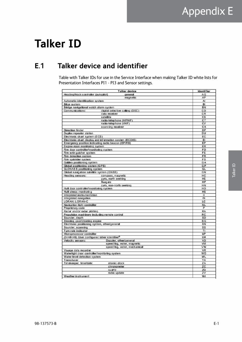
98-137573-B E-1
Appendix EEEEE
Talk
er ID
Talker ID E
E.1 Talker device and identifierTable with Talker IDs for use in the Service Interface when making Talker ID white lists for Presentation Interfaces PI1 - PI3 and Sensor settings.

Talker device and identifier
E-2 Appendix E: Talker ID 98-137573-B
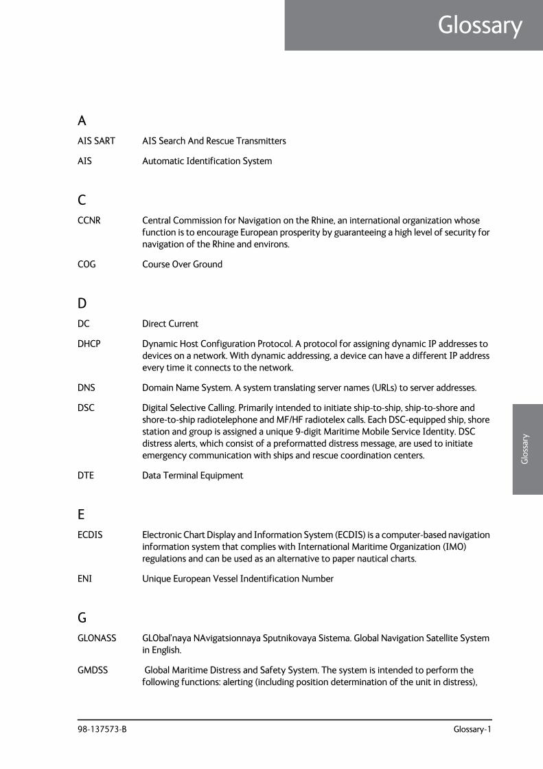
98-137573-B Glossary-1
6666
Glo
ssar
y
Glossary
Glossary 6
AAIS SART AIS Search And Rescue Transmitters
AIS Automatic Identification System
CCCNR Central Commission for Navigation on the Rhine, an international organization whose
function is to encourage European prosperity by guaranteeing a high level of security for navigation of the Rhine and environs.
COG Course Over Ground
DDC Direct Current
DHCP Dynamic Host Configuration Protocol. A protocol for assigning dynamic IP addresses to devices on a network. With dynamic addressing, a device can have a different IP address every time it connects to the network.
DNS Domain Name System. A system translating server names (URLs) to server addresses.
DSC Digital Selective Calling. Primarily intended to initiate ship-to-ship, ship-to-shore and shore-to-ship radiotelephone and MF/HF radiotelex calls. Each DSC-equipped ship, shore station and group is assigned a unique 9-digit Maritime Mobile Service Identity. DSC distress alerts, which consist of a preformatted distress message, are used to initiate emergency communication with ships and rescue coordination centers.
DTE Data Terminal Equipment
EECDIS Electronic Chart Display and Information System (ECDIS) is a computer-based navigation
information system that complies with International Maritime Organization (IMO) regulations and can be used as an alternative to paper nautical charts.
ENI Unique European Vessel Indentification Number
GGLONASS GLObal’naya NAvigatsionnaya Sputnikovaya Sistema. Global Navigation Satellite System
in English.
GMDSS Global Maritime Distress and Safety System. The system is intended to perform the following functions: alerting (including position determination of the unit in distress),
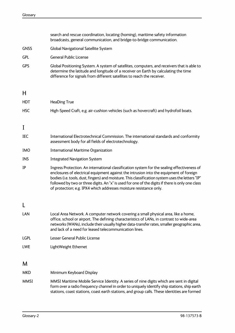
Glossary
Glossary-2 98-137573-B
search and rescue coordination, locating (homing), maritime safety information broadcasts, general communication, and bridge-to-bridge communication.
GNSS Global Navigational Satellite System
GPL General Public License
GPS Global Positioning System. A system of satellites, computers, and receivers that is able to determine the latitude and longitude of a receiver on Earth by calculating the time difference for signals from different satellites to reach the receiver.
HHDT HeaDing True
HSC High-Speed Craft, e.g. air-cushion vehicles (such as hovercraft) and hydrofoil boats.
IIEC International Electrotechnical Commission. The international standards and conformity
assessment body for all fields of electrotechnology.
IMO International Maritime Organization
INS Integrated Navigation System
IP Ingress Protection. An international classification system for the sealing effectiveness of enclosures of electrical equipment against the intrusion into the equipment of foreign bodies (i.e. tools, dust, fingers) and moisture. This classification system uses the letters "IP" followed by two or three digits. An "x" is used for one of the digits if there is only one class of protection; e.g. IPX4 which addresses moisture resistance only.
LLAN Local Area Network. A computer network covering a small physical area, like a home,
office, school or airport. The defining characteristics of LANs, in contrast to wide-area networks (WANs), include their usually higher data-transfer rates, smaller geographic area, and lack of a need for leased telecommunication lines.
LGPL Lesser General Public License
LWE LightWeight Ethernet
MMKD Minimum Keyboard Display
MMSI MMSI Maritime Mobile Service Identity. A series of nine digits which are sent in digital form over a radio frequency channel in order to uniquely identify ship stations, ship earth stations, coast stations, coast earth stations, and group calls. These identities are formed
Glossary
98-137573-B Glossary-3
6666
Glo
ssar
y
in such a way that the identity or part thereof can be used by telephone and telex subscribers connected to the general telecommunications network to call ships automatically.
MPE Maximum Permissible Emission
RRF Radio Frequency
ROT Rate Of Turn
Rx Receive
SSAR Search And Rescue
SART Search And Rescue Transponder
SOG Speed Over Ground.
SOLAS (International Convention for the) Safety Of Life At Sea. Generally regarded as the most important of all international treaties concerning the safety of merchant ships.
STP Shielded Twisted Pair
TTDMA Time-Division Multiple Access
TMA Thrane Management Application
TPI Threads Per Inch
Tx Transmit
UUART Universal Asynchronous Receiver/Transmitter, part of an integrated circuit used for serial
communications over a peripheral device serial port.
UDP User Datagram Protocol
VVDL VHF Data Link
VHF Very High Frequency. 30-300 MHz, a "straight-line" signal used for short-distance terrestrial communication and navigation.
Glossary
Glossary-4 98-137573-B
VSWR Antenna Voltage Standing Wave Ratio
VSWR Voltage Standing Wave Ratio
VTS Vessel Traffic Service, a marine traffic monitoring system established by harbour or port authorities, similar to air traffic control for aircraft.
WWIG Wing-In-Ground (craft)
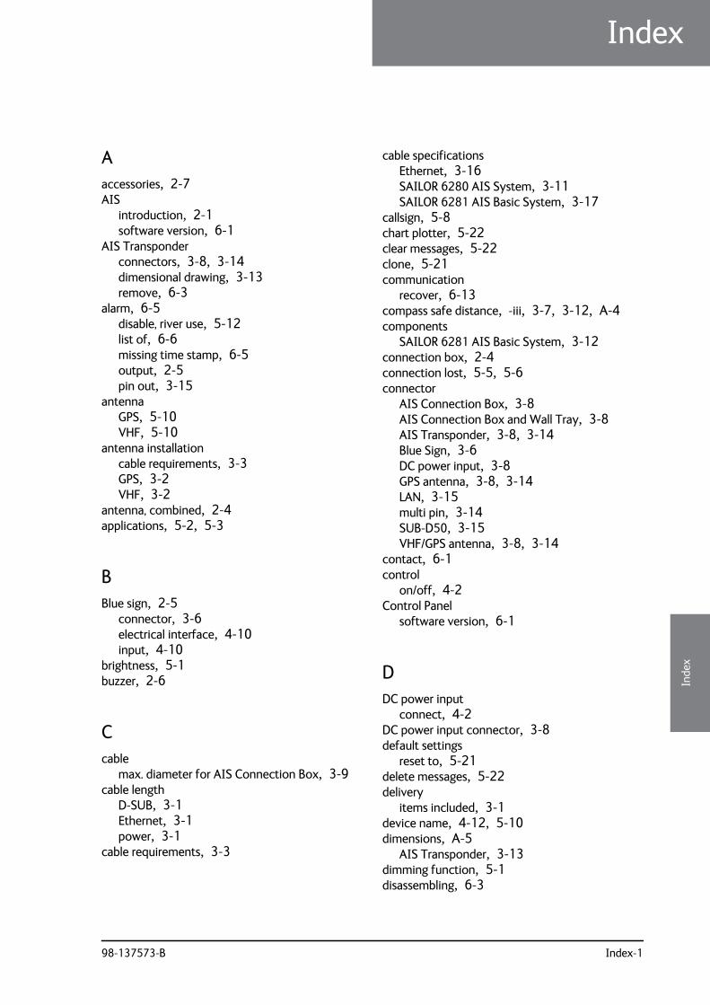
98-137573-B Index-1
77
77
Inde
x
Index
Index 7
Aaccessories, 2-7AIS
introduction, 2-1software version, 6-1
AIS Transponderconnectors, 3-8, 3-14dimensional drawing, 3-13remove, 6-3
alarm, 6-5disable, river use, 5-12list of, 6-6missing time stamp, 6-5output, 2-5pin out, 3-15
antennaGPS, 5-10VHF, 5-10
antenna installationcable requirements, 3-3GPS, 3-2VHF, 3-2
antenna, combined, 2-4applications, 5-2, 5-3
BBlue sign, 2-5
connector, 3-6electrical interface, 4-10input, 4-10
brightness, 5-1buzzer, 2-6
Ccable
max. diameter for AIS Connection Box, 3-9cable length
D-SUB, 3-1Ethernet, 3-1power, 3-1
cable requirements, 3-3
cable specificationsEthernet, 3-16SAILOR 6280 AIS System, 3-11SAILOR 6281 AIS Basic System, 3-17
callsign, 5-8chart plotter, 5-22clear messages, 5-22clone, 5-21communication
recover, 6-13compass safe distance, -iii, 3-7, 3-12, A-4components
SAILOR 6281 AIS Basic System, 3-12connection box, 2-4connection lost, 5-5, 5-6connector
AIS Connection Box, 3-8AIS Connection Box and Wall Tray, 3-8AIS Transponder, 3-8, 3-14Blue Sign, 3-6DC power input, 3-8GPS antenna, 3-8, 3-14LAN, 3-15multi pin, 3-14SUB-D50, 3-15VHF/GPS antenna, 3-8, 3-14
contact, 6-1control
on/off, 4-2Control Panel
software version, 6-1
DDC power input
connect, 4-2DC power input connector, 3-8default settings
reset to, 5-21delete messages, 5-22delivery
items included, 3-1device name, 4-12, 5-10dimensions, A-5
AIS Transponder, 3-13dimming function, 5-1disassembling, 6-3
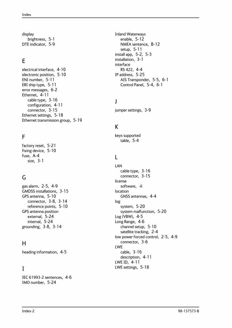
Index
Index-2 98-137573-B
displaybrightness, 5-1
DTE indicator, 5-9
Eelectrical interface, 4-10electronic position, 5-10ENI number, 5-11ERI ship type, 5-11error messages, 6-2Ethernet, 4-11
cable type, 3-16configuration, 4-11connector, 3-15
Ethernet settings, 5-18Ethernet transmission group, 5-19
Ffactory reset, 5-21fixing device, 5-10fuse, A-4
size, 3-1
Ggas alarm, 2-5, 4-9GMDSS installations, 3-15GPS antenna, 5-10
connector, 3-8, 3-14reference points, 5-10
GPS antenna positionexternal, 5-24internal, 5-24
grounding, 3-8, 3-14
Hheading information, 4-5
IIEC 61993-2 sentences, 4-6IMO number, 5-24
Inland Waterwaysenable, 5-12NMEA sentence, B-12setup, 5-11
install app, 5-2, 5-3installation, 3-1interface
RS 422, 4-4IP address, 5-25
AIS Transponder, 5-5, 6-1Control Panel, 5-4, 6-1
Jjumper settings, 3-9
Kkeys supported
table, 5-4
LLAN
cable type, 3-16connector, 3-15
licensesoftware, -ii
locationGNSS antennas, 4-4
logsystem, 5-20system malfunction, 5-20
Log (VBW), 4-5Long Range, 4-6
channel setup, 5-10satellite tracking, 2-4
low power forced control, 2-5, 4-9connector, 3-6
LWEcable, 3-16description, 4-11
LWE ID, 4-11LWE settings, 5-18
Index
98-137573-B Index-3
77
77
Inde
x
MMAC address
Control Panel, 5-4measures for installing, 3-13Message 5, 5-10messages
clear, 5-22MMSI
Missing MMSI, 6-12number, 5-24wrong MMSI, 6-12
MMSI number, 5-8multicast addresses, B-1
Nnight mode, 2-6, 5-1NMEA interface versions, 2-4NMEA sentence, B-1NMEA tracer, 5-26
Oon/off control, 4-2open source licences, 5-4own name, 4-12
Pparameters
set, 5-23part numbers, 2-7
accessories, 2-7password, 5-6
admin level, 5-13change, 5-13reset, 5-13user level, 5-13
PI settings, 5-14pilot plug, 2-4
connection, 4-8SAILOR 6283 AIS Connection Box and WallTray, 4-8
pin allocationDC connector, 4-1pilot plug, 4-8SUB-D50, 3-15
positionfixing device, 5-10GNSS antennas, 4-4reference points for GPS antenna, 5-10
position reference, 5-12power connector, 3-8presentation interfaces, 2-5, 4-6
baud rate, 4-7schematics, 4-7
Rradar, 2-2
distance to antenna installation, 3-4Rate of Turn, 4-5reboot
power cycle, 5-22recover communication, 6-13remote on/off
connect, 4-2remove AIS Transponder, 6-3reporting interval, A-2reset, 5-21
password, 5-13restore, 5-21restore from file, 5-21RF exposure, -iiiriver use
enable, 5-12NMEA sentence, B-12
Inland WaterwaysNMEA sentence, B-13
setup, 5-11ROT, 2-5RS 422 interfaces, 4-4
Ssafety distance, -iiiSAILOR 6280 AIS System
cable specifications, 3-11components, 3-6wiring, 3-10
SAILOR 6281 AIS Basic Systemcable specifications, 3-17components, 3-12wiring, 3-17
salt deposits, 6-1
Index
Index-4 98-137573-B
satellite equipmentdistance to antenna installation, 3-4
self test, 5-4Sensor
NMEA sentences, 5-16sensor inputs, 2-5, 4-3
baud rate, 4-4schematics, 4-3termination, 4-3
Sensor settings, 5-18Sentence White List, 5-15, 5-17, 5-19Service Interface
access, 5-4settings, 5-23
Ethernet, 5-18jumper, AIS Connection Box, 3-9LWE, 5-18PI, 5-14sensor, 5-18
ship name, 5-8ship type
table, 5-9software
uninstall, 5-3, 5-4software license, -iisoftware update
TMA, 6-2software version
AIS, 6-1Control Panel, 6-1TMA, 5-5
specifications, A-1SUB-D 50 connector
pin allocation, 3-15SUB-D50 connector, 3-14support, 6-1switching current
alarm, 4-9switching voltage
alarm, 4-9system ID, 5-10
TTalker ID White List, 5-15, 5-17, 5-19technical data, A-1ThraneLINK, 2-4time stamp
missing, alarm, 6-5
TMAadd search path, 6-2software update, 6-2software version, 6-2specific software, 6-3version, 5-5
tracer tool, 5-26transmission group, 5-19, B-1troubleshooting, 6-12
Uuninstall, 5-3, 5-4unpacking
items included, 3-1
VVDO/VDM sentences, 5-14verfication, 5-26VHF antenna, 5-10VHF RX/TX antenna installation, 3-4VHF/GPS antenna
connector, 3-8, 3-14VTS tool, 2-2
Wwarnings, 6-2warranty, -iii, 6-14waterproof, -iiiwire diameter
maximum for AIS Connection Box, 3-9wiring
SAILOR 6280 AIS System, 3-10SAILOR 6281 AIS Basic System, 3-17


98-137573-Bwww.cobham.com/satcom