Sail beamoct01
34
28-Oct-01 1 SailBeam Kare Technical Consulting SailBeam Space Propulsion by Macroscopic Sail-type Projectiles Presented at the 2001 NIAC Workshop Atlanta, GA October 30 - 31, 2001 Dr. Jordin T.Kare Kare Technical Consulting 222 Canyon Lakes Place San Ramon, CA 94583 925-735-8012 [email protected]
-
Upload
clifford-stone -
Category
Documents
-
view
55 -
download
0
Transcript of Sail beamoct01

28-Oct-01 1
SailBeam
Kare Technical Consulting
SailBeamSpace Propulsion by
Macroscopic Sail-type Projectiles
Presented at the2001 NIAC Workshop
Atlanta, GAOctober 30 - 31, 2001
Dr. Jordin T.KareKare Technical Consulting222 Canyon Lakes PlaceSan Ramon, CA 94583925-735-8012 [email protected]
28-Oct-01 2
SailBeam
Kare Technical Consulting
Laser Sails: A Quick Review
Laser
power Pwavelength λ
“Lens”
Area AtDiameter Dt
Sail
Mass/area σMass MsArea AsDiameter DsReflectivity η
Accelerationtime T
~ Dt Ds / λ Acceleration
2 η P • 1c Ms
• Infinite specific impulse • Efficient thrust at relativistic velocitiesBUT• Limited acceleration � large R (1012 km)• LARGE optics and sails - Dt • Ds ~ 109 m2
• Infinite specific impulse • Efficient thrust at relativistic velocitiesBUT• Limited acceleration � large R (1012 km)• LARGE optics and sails - Dt • Ds ~ 109 m2
Range R
Momentum flux P/c

28-Oct-01 3
SailBeam
Kare Technical Consulting
The SailBeam Concept
Momentum flux ~ ms * vs / t
Laser
power Pwavelength λ
“Lens”
Area AtN = At / NDiameter DtN = Dt / √N
N microsails
Mass/area σMass ms = Ms / NArea as = As / NDiameter ds = Ds / √NReflectivity η
Acceleration time:Total time TEach sail t = T / N
N sails accelerate over r ~ R / N
“Beam” of coasting microsails
• Vehicle accelerated by momentum transferfrom microsails• Same total time • Same laser power, BUT• Much smaller transmitter lens• Much smaller sails
• Vehicle accelerated by momentum transferfrom microsails• Same total time • Same laser power, BUT• Much smaller transmitter lens• Much smaller sails

28-Oct-01 4
SailBeam
Kare Technical Consulting
SailBeam Scaling
• For fixed sail velocity and mission energy* • Transmit aperture area at = At / N• Transmit aperture diameter dt = Dt / N1/2
• OR, For fixed laser power and aperture• Maximum sail velocity vs= Vs * N1/4
• Payload mass is limited only by mission energy
• In either case• High Flux at sail φφφφs(N) = φφφφs(1) * N• High Sail acceleration as = As * N
*Mission energy = laser power * laser run time

28-Oct-01 5
SailBeam
Kare Technical Consulting
Metal Sails Are Flux Limited
Incident flux I
Reflected flux R = ηηηη I
Thermal radiation ~ 2 εεεε A σσσσT4
εεεε emissivity T temperatureσσσσ Boltzmann’s const. A area
Absorbed power must be reradiatedI (1- ηηηη) = 2 εεεε σσσσT4
Absorption (1- ηηηη) is ~1% at bestAbsorption (1- ηηηη) is ~1% at bestηηηη reflectivity

28-Oct-01 6
SailBeam
Kare Technical Consulting
Dielectric Sails Beat the Flux Limit
Incident flux I
Reflected fluxR = I [(n2-1)/(n2+1)]2
n = index of refraction
Transmitted flux T = I - R - A
Absorbed flux A ~ I αααα tαααα = absorption coefficient
(1/absorption length)t = thickness
Absorption (αααα t) can be extremely small -- 10-12Absorption (αααα t) can be extremely small -- 10-12
I (αααα t) = 2 εεεε σσσσT4

28-Oct-01 7
SailBeam
Kare Technical Consulting
Microsail Performance Can Be Impressive
That’s 32 MILLION G’s“Zero to lightspeed in 0.97 seconds”
Wavelength 1 µmIndex of refraction 1.6Reflectioncoefficient
0.19
Sail thickness 0.156 µmDensity 2.6Areal density 406 mg/m2
Maximum laser flux 1014 W/m2Absorption 10-12Infrared emissivity 0.01 (nominal)Radiated power 100 W/m2Operating temp. ~684 KMaximum force 125 kN/m2Acceleration 3.1 x 10⁸ m/s2

28-Oct-01 8
SailBeam
Kare Technical Consulting
Vehicle Velocity Limit• Treat sail beam as continuous momentum flow
– dm/dt * v in laser frame – dm/dt * (v - vvehicle) in vehicle frame
• For vehicle mass = sail mass, vvehicle= 0.86 vsail
0.0
0.2
0.4
0.6
0.8
1.0
1.2
1.4
1.6
0 1 2 3 4
Vehicle mass / total sail mass
Vehicle final velocity
sail velocity
Energy efficiency
vs. single sail

28-Oct-01 9
SailBeam
Kare Technical Consulting
Sail Material Options
1 2 3 4 5
SiO2
Glass
Al2O3
SiO
ZrO2
TiO2
Am. diamond
Si (2 µm)
CVD diamond
1.5
1.6
1.62
1.9
2.0
2.4
2.6
3.4
4.41
0 1 2 3 4 5 6
1
2
3
4
5
6
7
8
9
2.6
2.6
4.0
2.18
5.4
4.3
3.5
2.3
3.5
0 1000 2000 3000
1
2
3
4
5
6
7
8
9
Refractive Index Density Melting Point
• CVD Diamond has the highest performance• SiO2 and Si have the largest technology base (IC industry)• Glass (doped SiO2) has the lowest bulk absorption (fiber optics)• ZrO2 (a common optical coating) is strong at high temperatures
28-Oct-01 10
SailBeam
Kare Technical Consulting
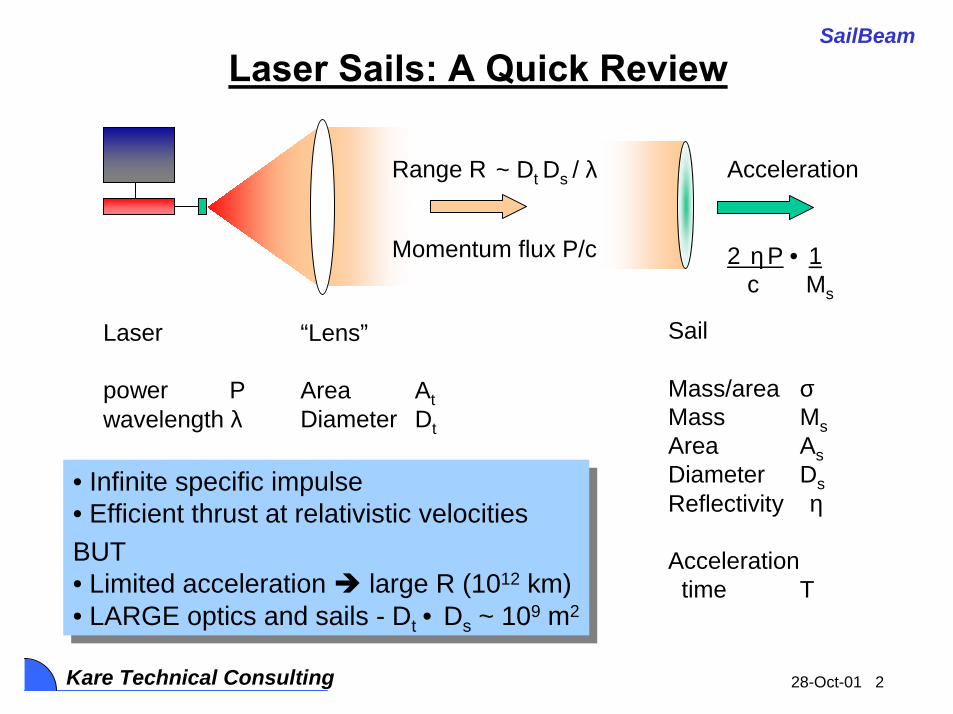
Multilayer Sails Are Usually Better
• R = (n2N - 1 / n2N + 1)2
– N quarter-wave layers spaced by quarter-wave vacuum
Multilayer Sail Accelerat(Vs. Single Layer)
0.0
0.5
1.0
1.5
2.0
2.5
3.0
1 1.5 2 2.5 3 3.5 4
Index of Refractio
2 Layers
34
Multilayer Reflectivity vs.
0
20
40
60
80
100
1 1.5 2 2.5 3 3.5 4
Index of Refractio
Single laye
2 Layers
34
If they can be fabricatedIf they can be fabricated
28-Oct-01 11
SailBeam
Kare Technical Consulting
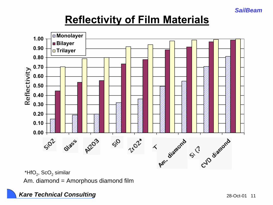
Reflectivity of Film Materials
0.00
0.100.20
0.300.40
0.50
0.600.70
0.800.90
1.00 MonolayerBilayerTrilayer
*HfO2, ScO2 similarAm. diamond = Amorphous diamond film

28-Oct-01 12
SailBeam
Kare Technical Consulting
0.0
1.0
2.0
3.0
4.0
5.0
6.0MonolayerBilayerTrilayer
8.7
Relative Acceleration, Fixed Flux• Reflectivity * index * λ / density determines acceleration (at fixed flux)
*HfO2, ScO2 similar All λ = 0.5µm except Si
28-Oct-01 13
SailBeam
Kare Technical Consulting
0.0
1.0
2.0
3.0
4.0
5.0
6.0
7.0
8.0MonolayerBilayerTrilayer
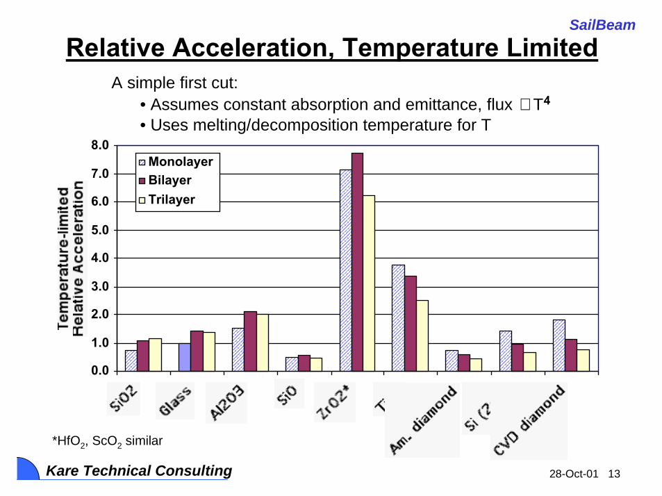
Relative Acceleration, Temperature LimitedA simple first cut:
• Assumes constant absorption and emittance, flux ∝ T4
• Uses melting/decomposition temperature for T
*HfO2, ScO2 similar

28-Oct-01 14
SailBeam
Kare Technical Consulting
Sample Point Designs
Blue = derived value
Vehicle Mass, kg 1000Vehicle Velocity, km/s 3 x 10 7
Acceleration range, km 65,000.0
10003.6 x 10 7
10,0003.6
Sail Mass, kgSail Velocity, km/sSail Accel., km/s 2Sail Accel. time, s
Sail Material Diamond Si 2 µm Glass (SiO2) Glass (SiO2)2 layers 2 layers 3 layers 1 layer
Laser wavelength, µm 0.5 2 0.5 0.5Laser Power, GW 25 25 25 100Density, g/cm 3 4.4 3.4 2.6 2.6
Refractive index 7.0 4.7 3.2 3.2
Sail Reflectivity 0.97 0.87 0.79 0.19
Layer thickness, µm 0.04 0.21 0.08 0.08
Areal density, mg/m 2 314 1459 609 203
Sail Diameter, m 0.26 0.11 0.16 0.28Telescope Dia., m 310 2820 480 280Sail Mass, mg 16 14 13 13
of sails, millions 62 69 77 79
Total accel. time, years 7.1 7.9 8.8 9.0

28-Oct-01 15
SailBeam
Kare Technical Consulting
Potential Limits on Microsails
• Absorption• Mechanical strength / beam uniformity• Stability and beam tracking• Sail structure and attachments
– Nothing but a dielectric film can survive 100 MW/cm2 for long
• Sail guidance– How to hit the vehicle’s “sweet spot” over a light-year?
• Momentum transfer– How to do it?– Impact limits -- even 0.0001 kg packs a large punch at 0.1 c– Inelasticity -- how much energy ends up in the vehicle?
28-Oct-01 16
SailBeam
Kare Technical Consulting
Thin Layer Absorption / Damage
• Damage thresholds not well known– Most data are from multilayer reflectors and sub-µs laser pulses
• Not directly applicable to single-layer microsails, CW laser– Bulk of recent data are on SiO2 and HfO2
• Film absorption is typically 10-6 or higher – Several orders of magnitude higher than bulk absorption– Heavily dependent on fabrication method
• Usual methods (sputtering, vapor deposition) deposit porous layers, varying amounts of impurities
• Low absorption was rarely the main goal of process development
– Bulk absorption appears to dominate, but surface absorption is significant• Measurements are indirect and quite difficult

28-Oct-01 17
SailBeam
Kare Technical Consulting
Thin Layer Absorption / Damage (2)
• SailBeam allowable absorption is design-dependent– Flux limit depends on material emissivity and temperature limits– Transmitter aperture diameter varies as (max flux)-1/2
– 10-10 absorption probably acceptable; >10-8 presents problems
• Conclusion: R&D needed– Experimental measurement of limiting flux
• Long pulses (~millisecond) and single-layer films– Process development and/or “new” processes to reduce
absorption, e.g.,• Pulling of bulk material (flat version of fiber optic fabrication)• Doping and etching of thick wafers(Processes used to make thin structures in other fields, but not
usually used for optical films))

28-Oct-01 18
SailBeam
Kare Technical Consulting
Spin Stabilization• Microsail must be stable in beam
– Characteristic time scale ~ [2(sail diameter)/(acceleration)]1/2
• Typically ~100 µs (e.g., 0.1 m sail, 2 x 10⁷ m/s2 accel.)• << Lightspeed feedback time to transmitter; can’t do active
stabilization• Spin rate must be ~10,000 rps
– Spin provides at least neutral stability• Other projects are investigating stability for other beam-
driven systems (e.g., Benford et al., microwave sails)– Active damping of oscillations is possible
• On-sail guidance components, or• Platforms spaced along sail acceleration path
• Spin keeps sail in tension– Prevents collapse or wrinkling due to nonuniform beam / loads

28-Oct-01 19
SailBeam
Kare Technical Consulting
Much Work Remains To Be DoneMuch Work Remains To Be Done
Guiding Microsails• Sails will need some course correction capability
– Finite velocity error at launch: 1 nrad error => 1 km miss at 0.1 l.y.– Sail will be perturbed in flight, e.g., by dust impacts – Main laser is too diffuse to apply corrections even 1 light-day out
• At least two options:– “Guidance stations” along path to ~1 light day
• Can measure course to <<1 nrad and correct with laser pulses– Measuring sail-to-sail relative errors is sufficient
• Corrections extend beyond most solar-system perturbations• No requirements on sails, but may not be accurate enough
– MEMS micropropulsion on sails• Few m/s ∆V is sufficient, and feasible even at very small scales• Vehicle can provide a “homing beacon” laser• Sail sensors and control system are simple, but not trivial

28-Oct-01 20
SailBeam
Kare Technical Consulting
Tensile Strength• Tensile loads are comparable to force on sail
– Centrifugal load due to spin stabilization– Acceleration loads on “payload” or low-illumination area
• Tensile strengths of freestanding thin films are poorly known– Highly variable, depending on film fabrication details
But some typical values are• Al2O3 0.25 GPa (1 GPa ~150,000 psi)• Si 1 GPa• SiO2 2 GPa• CVD diamond 3.5 GPa
• Nominal requirement is σσσσsail ~ msail asail / (dsail tsail)– tsail is the sail thickness, nominally λλλλ/4n– Typical values are 3 - 10 GPa (for 107 m/s2 acceleration)
Tensile strength looks OK, but only barely --may drive many aspects of sail and system design
Tensile strength looks OK, but only barely --may drive many aspects of sail and system design

28-Oct-01 21
SailBeam
Kare Technical Consulting
Microsail Conceptual Design
Laser beam profile• Flux at “payload” is low
MEMSguidance/propulsion“payload”
Curvature distributesacceleration load
Si bi-layer, withSi grid spacer

28-Oct-01 22
SailBeam
Kare Technical Consulting
Coupling Microsails To Macroscopic Vehicles1. Magnetic Coupling• Turn microsail into plasma
– Use a laser on the vehicle (at a wavelength absorbed by sail), or– Run it into something
• Plasma cloud (Landis shield)• Gas/dust cloud (residue of previous sail?)• Solid film or mesh (mass << sail)
• Transfer momentum to vehicle– Bounce plasma off a magnetic field (MagOrion concept)
• Elastic; low energy absorption
2. Or emulate ORION– Let solid (or perhaps vaporized) sail hit something
• A solid pusher plate• A confined gas or plasma
– Reject impact energy via ablated mass or radiation

28-Oct-01 23
SailBeam
Kare Technical Consulting
Ionizing Microsails• Laser
– Use wavelength absorbed by sail, probably UV– Thin sail is easy for laser to ablate (vs., e.g., spherical particle)– Requires ~50 - 100 MJ / kg -- <1 kJ for typical microsail
• 3 - 10 kJ needed for safety margin, pointing error, etc. – Sail expands into spherical plasma at ~10 km/s
• Must hit sail 0.01 - 0.1 s before impact at 10’s to 100’s of km• Must track sail with ~0.1 m accuracy at 105 m
• Impact -- proposed by Singer in original 1980 particle-beam paper
– Let microsail strike something -- solid, particle cloud, gas, plasma• High-velocity impact produces X-ray temperatures
– Low energy requirement, but possibly complex hardware– Vehicle must carry sacrificial mass
• Specific impulse is no longer infinite• Cleverness needed to “hit” sail without tossing away >>msail

28-Oct-01 24
SailBeam
Kare Technical Consulting
MagSail Concept
Solar Wind MagSail
Plasma BowShock
MagSailMagnetic
Field
β=0.01 TeslaPlasma
Interface Shock
MagSail Magnetic Field(compressed)
β=0.01 Tesla
Nuclear Propellant(Detonated 2 km Behind MagSail)
Solar-wind-driven MagSail Nuclear-pulse-driven MagOrion

28-Oct-01 25
SailBeam
Kare Technical Consulting
0.0001
0.0010
0.0100
0.1000
1.0000
10 100 1000 10000
Loop Radius, meters
.02c Reflectio
.1c Reflectio
.02c Deflectio
.1c Deflectio
• Collective plasma reflection(Dynamic pressure)
• Individual ion deflection (Larmor radius)
Estimating MagSail Requirements
B2 / 2µ0 >> msailVrel2 /π rloop
3
mionVrel / q B << rloop
• Nominal design point– 100 m loop radius– 16 MA loop current– 1000 kg loop mass – 1 x 10⁷ Amp-m / kg
superconductor performance

28-Oct-01 26
SailBeam
Kare Technical Consulting
MagSail Drag
Ni = Number density of ions(nominally 105 m-3, or 0.1/cm3)
mi = Average ion mass (1 amu)µ0 = 4π x 10-7
I = Loop currentr = Loop radiusV = Vehicle velocity
Fdrag =1.175π(Ni mi µ01/ 2 I r2 V2 )2 / 3
For V=0.1c, r=100m, I=16 MA• Fdrag = 34 N; Thrust ~ 8 N
For V=0.1c, r=100m, I=16 MA• Fdrag = 34 N; Thrust ~ 8 N

28-Oct-01 27
SailBeam
Kare Technical Consulting
Suppressing Drag During Acceleration
• Drag is dominated by low-field region far from loop
• 2nd larger loop with opposite dipole cancels field– For constant dipole moment, current I varies as 1/r2
– Central field proportional to I/r, varies as 1/r3
• Outer loop doesn’t affect propulsive MagSail– Mass is proportional to I r, so varies as 1/r.
• Expect drag < 1 N at 0.1c – Nominally 100m inner and 1 km outer loop radii– Modeling and optimization needed

28-Oct-01 28
SailBeam
Kare Technical Consulting
How To Stop When You Get There• Redeploy MagSail conductor into drag brake
– Very large, low-current loop– B field pressure ~ dynamic pressure of interstellar medium– Ideally, continue to expand loop as velocity falls– Brake to rest against stellar wind once velocity is <500 km/s
100
1000
10000
100000
0 10 20 30
Deceleration time (Years
Parameter Value CommentVehicle mass, kg 1000 excluding
brake loopInitial velocity, km/s 30,000 0.1 c
Interstellar ion density, #/m3 105 0.1 ion/cm3
Initial dynamic pressure, N/m2 7.7 x 10⁻⁸
Brake loop radius, km 28Brake loop current, kA 55Magnetic field pressure, N/m2 6.1 x 10⁻⁷ B2/2µSuperconductor J/rho, A-m/kg 107
Brake loop mass, kg 968
Initial drag force, N 1405

28-Oct-01 29
SailBeam
Kare Technical Consulting
Precursor Missions• Microsails can transmit energy as well as momentum
– Thrust can be generated in any direction• Allows rendezvous and return missions
– Requires energy conversion to drive thruster• Direct, e.g., run sail into a contained plasma• Indirect, e.g., compress magnetic field to produce current to drive a
plasma thruster
• Efficiency is low compared to alternatives... – Efficiency is at best sail velocity/c; can’t scale down sail
velocity (and therefore laser/optics size) by much– Probably not competitive below 0.01 c = 3000 km/s
• ...But a prime alternative is laser propulsion– Laser-thermal (pulsed ablation) or laser-electric– Suitable for missions up to perhaps 0.02 c– Direct technology precursors (lasers, optics) for SailBeam

28-Oct-01 30
SailBeam
Kare Technical Consulting
Comparing Energy Requirements
1
10
100
1000
10000
100000
100 1000 10000
Velocity, km/s
Efficient thruste
Momentum beam
Energy beam
25% thruster efficien
(thruster, energy bea
90% sail reflectivity
to accelerate 1000 kg to various velocities

28-Oct-01 31
SailBeam
Kare Technical Consulting
Near Term Experiments• “Sail” diameters ~1 mm or less
– Still a thin film: >>1000:1 width:thickness– Variety of materials and fabrication processes available
• Laser pulse power ~1 MW– 1 MW of laser power yields ~1 million G acceleration
• Laser pulse lengths ~ 1 msec– Final velocities of 10 - 30 km/s– Suffiicient to demonstrate stable acceleration
• Existing facilities meet requirements– E.g., LHMEL (Air Force Wright-Patterson)
• 1 kJ Nd-Glass flashlamp-pumped laser• ~1 msec “dump” mode
– Experiments fit in a 5 - 50 meter long vacuum pipe

28-Oct-01 32
SailBeam
Kare Technical Consulting
Near Term (Phase 2) Experiment Goals• Measure damage/failure flux for films
– Test likely materials under CW conditions– Develop and test alternate film fabrication methods
• Demonstrate “static thrust” – MEMS force gauges integrated with film
• Demonstrate enhanced thrust with multilayers• Measure film absorption and thermal balance
– Difficult but not unprecedented measurements – Use photoacoustic or photoelastic techniques plus IR
radiometry
• Demonstrate “free flight” acceleration to >10 km/s

28-Oct-01 33
SailBeam
Kare Technical Consulting
Force Measurement ConceptSi cantilever spring
Capacitive displacement sensor
Test film
Si Support structure
1 mm
Reflectedpower sensor
IR emissionsensor

28-Oct-01 34
SailBeam
Kare Technical Consulting
Conclusions
• Real interstellar probes are possible– 0.1 c or faster; Alpha Centauri in 10 years?– Multi-kg (or even multi-ton) payloads
• System requirements are (relatively) modest– ~0.2 GW-year of laser output per kg to 0.1 c– Sub - kilometer scale optics– Sub-meter scale thin film sails
• Development can be done soon– Development path overlaps with laser propulsion/beamed
energy – Key aspects are small scale, e.g., thin film absorption
• Real experiments can start right away