SAIA PCD LON WORKS Process Control Devices with SAIA lon works networks manual.pdf · Process...
182
Edition 26/767 E2 SAIA ® PCD Process Control Devices Manual LON WORKS ® Networks with SAIA ® PCD
Transcript of SAIA PCD LON WORKS Process Control Devices with SAIA lon works networks manual.pdf · Process...
Edition 26/767 E2
SAIA®PCDProcess Control Devices
ManualLON WORKS® Networkswith SAIA®PCD
SAIA-Burgess Electronics Ltd.Bahnhofstrasse 18CH-3280 Murten (Switzerland)http;//www.saia-burgess.com
BA: Electronic Controllers Telephone 026 / 672 71 11Telefax 026 / 670 44 43
___________________________________________________________________________________________________________________________
SAIA-Burgess Companies
Switzerland SAIA-Burgess Electronics AGFreiburgstrasse 33CH-3280 Murten 026 672 77 77, Fax 026 670 19 83
France SAIA-Burgess Electronics Sàrl.10, Bld. Louise MichelF-92230 Gennevilliers 01 46 88 07 70, Fax 01 46 88 07 99
Germany SAIA-Burgess Electronics GmbHDaimlerstrasse 1kD-63303 Dreieich 06103 89 060, Fax 06103 89 06 66
Nederlands SAIA-Burgess Electronics B.V.Hanzeweg 12cNL-2803 MC Gouda 0182 54 31 54, Fax 0182 54 31 51
Austria SAIA-Burgess Electronics Ges.m.b.H.Schallmooser Hauptstrasse 38A-5020 Salzburg 0662 88 49 10, Fax 0662 88 49 10 11
Belgium SAIA-Burgess Electronics BelgiumAvenue Roi Albert 1er, 50B-1780 Wemmel 02 456 06 20, Fax 02 460 50 44
Italy SAIA-Burgess Electronics S.r.l.Via Cadamosto 3I-20094 Corsico MI 02 48 69 21, Fax 02 48 60 06 92
Hungary SAIA-Burgess Electronics Automation Kft.Liget utca 1.H-2040 Budaörs 23 501 170, Fax 23 501 180
Representatives
Great Britain Canham Controls Ltd.25 Fenlake Business Centre, FengatePeterborough PE1 5BQ UK 01733 89 44 89, Fax 01733 89 44 88
Portugal INFOCONTROL Electronica e Automatismo LDA.Praceta Cesário Verde, No 10 s/cv, MassamáP-2745 Queluz 21 430 08 24, Fax 21 430 08 04
Denmark Malthe Winje Automation ASHåndværkerbyen 57 BDK-2670 Greve 70 20 52 01, Fax 70 20 52 02
Spain Tecnosistemas Medioambientales, S.L.Poligono Industrial El Cabril, 9E-28864 Ajalvir, Madrid 91 884 47 93, Fax 91 884 40 72
Norway Malthe Winje Automasjon ASHaukelivn 48N-1415 Oppegård 66 99 61 00, Fax 66 99 61 01
CzechRepublic
ICS Industrie Control Service, s.r.o.Modranská 43CZ-14700 Praha 4 2 44 06 22 79, Fax 2 44 46 08 57
Sweden Malthe Winje Automation ABTruckvägen 14AS-194 52 Upplands Våsby 08 795 59 10, Fax 08 795 59 20
Poland SABUR Ltd.ul. Druzynowa 3APL-02-590 Warszawa 22 844 63 70, Fax 22 844 75 20
Suomi/Finland
ENERGEL OYAtomitie 1FIN-00370 Helsinki 09 586 2066, Fax 09 586 2046
Australia Siemens Building Technologies Pty. Ltd.Landis & Staefa Division411 Ferntree Gully RoadAUS-Mount Waverley, 3149 Victoria
Argentina MURTEN S.r.l.Av. del Libertador 184, 4° “A”RA-1001 Buenos Aires 054 11 4312 0172, Fax 054 11 4312 0172
3 9544 2322, Fax 3 9543 8106
After sales service
USA SAIA-Burgess Electronics Inc.1335 Barclay BoulevardBuffalo Grove, IL 60089, USA 847 215 96 00, Fax 847 215 96 06
___________________________________________________________________________________________________________________________Issue : 22.11.2000
Subjet to change without notice
SAIA-Burgess Electronics Ltd.
SAIA® Process Control Devices
LON WORKS® Networks
with SAIA® PCD
SAIA-Burgess Electronics Ltd. 1999 - 2000. All rights reservedEdition 26/767 E2 - 08.2000
Subject to technical changes
SAIA-Burgess Electronics Ltd.
Updates
Manual : LON WORKS® Networks with SAIA® PCD - Edition E2
Date Chapter Page Description
PCD4 Contents
26/734 E7 (D4-00-E.DOC) SAIA-Burgess Electronics Ltd. Page 1
Contents
Page
1. Philosophy and main elements of LON
1.1 The idea behind LON (philosophy) 1-11.2 The four elements of LON 1-21.3 The LonTalk protocol 1-3
1.3.1 Basic structure 1-31.3.2 What is CSMA ? 1-61.3.3 OSI layer 1-71.3.4 Address allocation 1-81.3.5 Addressing modes 1-111.3.6 Explicit messages 1-121.3.7 Network variables 1-131.3.8 Configuration and network management 1-14
1.4 Nodes 1-15
1.4.1 NEURON -based nodes 1-151.4.2 Single chip processor 3120 1-201.4.3 Multiple chip processor 3150 1-201.4.4 Open protocol implementations 1-201.4.5 MIP (Micro Processor Interface Program) 1-211.4.6 HOST node (NMN Network Management Node) 1-21
1.5 LonWorks transceivers 1-22
1.5.1 Twisted Pair TP 78 1-221.5.2 Free Topology FTT-10 1-231.5.3 RS-485 1-231.5.4 Link Power 1-241.5.5 Power Line 1-241.5.6 Other transceivers 1-26
1.6 LonWorks Tools 1-27

Contents PCD4
Page 2 SAIA-Burgess Electronics Ltd. (D4-00-E.DOC) 26/734 E7
Page
2. The LonMark Standard
2.1 Physical Layer (Layer 1) 2-12.2 Layer 2 - 6 2-22.3 Application Layer (Layer 7) 2-32.4 LonMark objects 2-4
2.4.1 Structure of a LonMark object 2-42.4.2 Node object 2-62.4.3 Sensor objects 2-82.4.4 Actuator objects 2-102.4.5 Controller object 2-112.4.6 Function profiles 2-13
3. Components of a network
3.1 Nodes 3-13.2 Network organization components 3-2
3.2.1 Repeater 3-23.2.2 Bridges 3-23.2.3 Learning Router 3-23.2.4 Configured Router 3-33.2.5 Why use routers ? 3-3
3.3 System limits and tips for overcoming them 3-4
3.3.1 Domain restrictions 3-43.3.2 Limited number of groups 3-43.3.3 Limited number of channel parties 3-53.3.4 Limited number of address tables 3-5
4. SAIA PCD devices for the LON network
4.1 LON host module PCD7.F80x 4-14.2 Operating modes 4-7

PCD4 Contents
26/734 E7 (D4-00-E.DOC) SAIA-Burgess Electronics Ltd. Page 3
Page
5. Planning and installation of a LON network
6. LON configurator
6.1 General 6-26.2 Procedure for LON configuration 6-36.3 LON configurator menu: calling and description 6-4
6.3.1 Opening a new project 6-46.3.2 Structure of main screen 6-5
6.4 Menus of the LON configurator 6-10
6.4.1 Structure of the 'Network' submenu 6-116.4.2 Structure of the 'Edit' submenu 6-136.4.3 Structure of the 'View' submenu 6-146.4.4 Structure of the 'Library' submenu 6-156.4.5 Structure of the 'Project' submenu 6-166.5.6 Structure of the 'Online' submenu 6-176.4.7 Structure of the 'Window' submenu 6-186.4.8 Structure of the 'Help' submenu 6-19
7. Programming in the user program
Content of the LON library 7-1
8. Configuring LON parameters for xx7 SeriesPCDs and LON access with S7
8.1 SNET32 8-2
8.1.1 Installation 8-28.1.2 Beginning a configuration 8-38.1.3 Configuring a PCD station 8-4
8.2 Definition of NVs (Network Variables 8-5
8.2.1 Variable list 8-58.2.2 New Variable 8-6
8-3 Exporting the LON configuration 8-8
8.3.1 Export options 8-88.3.2 Creating and exporting the configuration 8-9
SIMATIC is a registered trademark of Siemens AG

Contents PCD4
Page 4 SAIA-Burgess Electronics Ltd. (D4-00-E.DOC) 26/734 E7
Page
8.4 Importing the configuration under SIMATIC® S7 8-10
8.4.1 Importing the source file 8-108.4.2 Compiling the source file 8-11
8.5 LON access with S7 8-12
8.5.1 Data-block information 8-128.5.2 Configuration data-block (base address) 8-128.5.3 Network Variable DB (base address +1) 8-138.5.4 Explicit message DB (base address +2) 8-138.5.5 Diagnostic Flag DB (base address +3) 8-148.5.6 Working with symbolic names 8-15
8.6 System functions for LON 8-16
8.6.1 Initialization with SFC 220 "LON_INIT" 8-168.6.2 SEND NV mit SFC221 "LON_NV_SEND" 8-188.6.3 SEND Messages with SFC 223 "LON_MSG_SEN" 8-198.6.4 Error Code 8-20
8.7 Diagnostic and error OB 8-218.8 Restrictions 8-22
9. Commissioning and debugging
9.1 History messages 9-29.2 Additional information about LON with SAIA PCD 9-4
10. Terminology, abbreviations, register of sources
10.1 Terminology 10-110.2 Abbreviations 10-1410.3 Register of sources 10-15
SIMATIC is a registered trademark of Siemens AG

PCD4 Contents
26/734 E7 (D4-00-E.DOC) SAIA-Burgess Electronics Ltd. Page 5
Please note :A number of detailed manuals are available to aid installation andoperation of the SAIA® PCD. These are for use by technicallyqualified staff, who may also have successfully completed one of our"workshops".
To obtain the best performance from your SAIA® PCD, closely followthe guidelines for assembly, wiring, programming and commissioninggiven in these manuals. In this way, you will also become one of themany enthusiastic SAIA® PCD users.
If you have any technical suggestions or recommendations forimprovements to the manuals, please let us know. A form is providedon the last page of this manual for your comments.
Summary
HardwareP CD4
H ardware P CD6
PCD4.H1..
PCD4.H2..
PCD4.H3..
Reference Guide(PG3)
PC D8.P1..
- PCD7.D1..- PCD7.D202- PCD7.D250- PCD7.D7..
Insta llat ionC om ponentsfor R S 485-N etwo rk s
FUPLA/KOPLAfunctionfamilies
PCD1/2 series PCD4 series PCD6 series
GeneralManuals
*)
*)
*)*) Adapter module 4 '717 '4828'0 allows H modules to be used with the P CD6.
U ser'sG uide
- PG4- Modem
- LON- S-Bus- PROFIBUS
PCD4.H4..
HardwarePCD 1PCD 2Serie xx7
PCD2.M250
PCD2.H110PCD2.H150PCD2.H210PCD2.H31x

Contents PCD4
Page 6 SAIA-Burgess Electronics Ltd. (D4-00-E.DOC) 26/734 E7
Reliability and safety of electronic controllers
SAIA-Burgess Electronics Ltd. is a company which devotes the greatestcare to the design, development and manufacture of its products :
• state-of-the-art technology
• compliance with standards
• ISO 9001 certification
• international approvals : e.g. Germanischer Lloyd,United Laboratories (UL), Det Norske Veritas, CE mark ...
• choice of high-quality componentry
• quality control checks at various stages of production
• in-circuit tests
• run-in (burn-in at 85°C for 48h)
Despite every care, the excellent quality which results from this doeshave its limits. It is therefore necessary, for example, to reckon with thenatural failure of components. For this reason SAIA-Burgess ElectronicsLtd. provides a guarantee according to the "General terms and conditionsof supply".
The plant engineer must in turn also contribute his share to the reliableoperation of an installation. He is therefore responsible for ensuring thatcontroller use conforms to the technical data and that no excessivestresses are placed on it, e.g. with regard to temperature ranges,overvoltages and noise fields or mechanical stresses.
In addition, the plant engineer is also responsible for ensuring that afaulty product in no case leads to personal injury or even death, nor tothe damage or destruction of property. The relevant safety regulationsshould always be observed. Dangerous faults must be recognized byadditional measures and any consequences prevented. For example,outputs which are important for safety should lead back to inputs and bemonitored from software. Consistent use should be made of thediagnostic elements of the PCD, such as the watchdog, exceptionorganization blocks (XOB) and test or diagnostic instructions.
If all these points are taken into consideration, the SAIA PCD willprovide you with a modern, safe programmable controller to control,regulate and monitor your installation with reliability for many years.

LON Philosophy and main elements of LON
26/767 E1 (LON-01-E.DOC) SAIA-Burgess Electronics Ltd. Page 1-1
1. Philosophy and main elements of LON
1.1 The idea behind LON (philosophy)
LON, the Local Operating Network, brings computer networks to thechip. This is the vision of ECHELON’s founders. The technology strivesto enable network construction out from large number of low-cost, nodes.These nodes can be produced by different manufacturers and communi-cate with each other by means of the LonTalk® protocol.All nodes possess their own intelligence and are capable of event con-trolled data exchange between each other. The nodes measure, control,regulate and communicate. This results in an extremely flexible networkof functions with almost any desired level of cross-linking or complexity.
N
N
N N
N NN
Figure 1: Decentralized nodes
From the start, realization not standardization was the motto of the tech-nology’s founders grouped around A.C. Markkula. He had previously al-ready been able to make a name for himself with Intel and Apple as amanager of high-tech firms in the pioneering stage.By making available a chip with an integral communication systemECHELON succeeded, by rapidly spreading, in creating a quasi-standard.At its core was the LonTalk® protocol, which was only made availablethrough these specific chips until such time as the standard had devel-oped.At the current time, the protocol is now being standardized and releasedfor implementation on other chips. LonWorks has found its way intomany standards, such as BACNET (ASHRAE American Society ofHeating and Air-Conditioning Engineers), ISFS (International Interna-tional Forecourt Standard Forum, i.e. all major oil companies), CEN TC-247, SEMI (mass flow meters), CELECT (UK for heating) and IEC708.1..708.3.The most important standard is LonMark , an organisation founded byECHELON comprising LON component suppliers who have imposed thisstandard on themselves.LonTalk can be seamlessly transmitted across two-wire lines, 230V net-works, fibre-optics, radio and Ethernet networks.

Philosophy and main elements of LON LON
Page 1-2 SAIA-Burgess Electronics Ltd. (LON-01-E.DOC) 26/767 E1
1.2 The four elements of LON
LonTalkProtocol
LonWorksTransceiver
LonWorksTools
NeuronChips
LonWorks technology is based on four fundamental elements:
• The LonTalk protocol defines the language which will be spoken onthe LON medium.
• The neuron chips can interpret this language and form nodes capableof executing cross-linked functions with the LonTalk language.
• The LonWorks transceivers can project LonTalk onto various physi-cal media, so that the language can be transmitted across a wide vari-ety of communications channels.
In conclusion, these tools form the backbone of product development andinstallation planning or execution. A corresponding distinction is drawnbetween development tools (LonBuilder, NodeBuilder) and installationtools (LonMaker, ICELAN-G, Helios).
LON Philosophy and main elements of LON
26/767 E1 (LON-01-E.DOC) SAIA-Burgess Electronics Ltd. Page 1-3
1.3 The LonTalk protocol
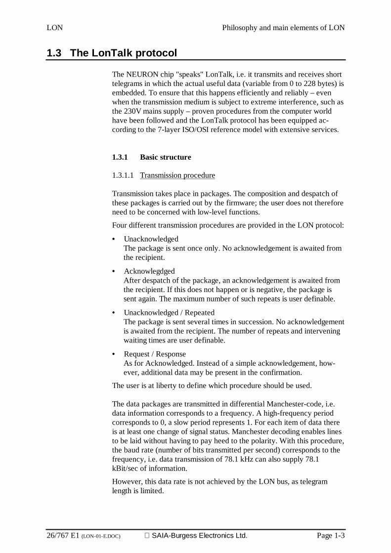
The NEURON chip "speaks" LonTalk, i.e. it transmits and receives shorttelegrams in which the actual useful data (variable from 0 to 228 bytes) isembedded. To ensure that this happens efficiently and reliably – evenwhen the transmission medium is subject to extreme interference, such asthe 230V mains supply – proven procedures from the computer worldhave been followed and the LonTalk protocol has been equipped ac-cording to the 7-layer ISO/OSI reference model with extensive services.
1.3.1 Basic structure
1.3.1.1 Transmission procedure
Transmission takes place in packages. The composition and despatch ofthese packages is carried out by the firmware; the user does not thereforeneed to be concerned with low-level functions.
Four different transmission procedures are provided in the LON protocol:
• UnacknowledgedThe package is sent once only. No acknowledgement is awaited fromthe recipient.
• AcknowlegdgedAfter despatch of the package, an acknowledgement is awaited fromthe recipient. If this does not happen or is negative, the package issent again. The maximum number of such repeats is user definable.
• Unacknowledged / RepeatedThe package is sent several times in succession. No acknowledgementis awaited from the recipient. The number of repeats and interveningwaiting times are user definable.
• Request / ResponseAs for Acknowledged. Instead of a simple acknowledgement, how-ever, additional data may be present in the confirmation.
The user is at liberty to define which procedure should be used.
The data packages are transmitted in differential Manchester-code, i.e.data information corresponds to a frequency. A high-frequency periodcorresponds to 0, a slow period represents 1. For each item of data thereis at least one change of signal status. Manchester decoding enables linesto be laid without having to pay heed to the polarity. With this procedure,the baud rate (number of bits transmitted per second) corresponds to thefrequency, i.e. data transmission of 78.1 kHz can also supply 78.1kBit/sec of information.
However, this data rate is not achieved by the LON bus, as telegramlength is limited.

Philosophy and main elements of LON LON
Page 1-4 SAIA-Burgess Electronics Ltd. (LON-01-E.DOC) 26/767 E1
Differential Manchester code withoutDC portion for chosen media
Bit synchronisation adjustable toTransmission medium
Variable useful data: 1- 228 Bytes1 1 0 0 1 0 1
800ns by 1,25MBit/s
Bit synchr.7-n x 1
2 ControlBytes
Node address3-9 Bytes
Domain address0-6 Bytes
Bytesynchr. (0)
Dataheader
Useful data1-228 Bytes
CRC-16(CCITT)Code demage for
frame synchr. (>2 Bit)
Bit coding
Telegram structure
Figure 3: Data format
A telegram always comprises synchronization bits (sequence of “1”) ad-justable to the relevant transceiver. These synchronization bits are for thetransceiver circuit, so that it can build up to the receive frequency. Thefirst 0 indicates the beginning of address data, which shows the receivingnode whether it should pay any attention at all to the incoming telegram.The address is followed by useful data or by ACK/NACK bytes to indi-cate whether a message has been successfully received.
1.3.1.2 Data protection
With open bus systems the option of additional data protection can beprovided. In a special transmission procedure, the receiver can check theauthenticity of the sender. For this purpose, a 48-bit code number isagreed between the sender and the receiver during installation of thenetwork. This code is independent of the chip-specific identificationnumber. The code number is transmitted with a different ciphering pro-cedure at each transmission, guaranteeing a high level of security.
If a node receives an authenticated message, it asks the sender to proveits authorization. For this purpose it sends a 64-bit random number forencryption. The sender encodes this number using its keyword and re-turns the result. The receiver compares this answer with the result of itsown encryption. If they match, the receiver’s network CPU accepts theoriginal message and forwards it to the application program. Otherwise,the receiving node ignores the original telegram and increments an errorcounter. Authentication can be defined for each separate network vari-able and for network management commands.

LON Philosophy and main elements of LON
26/767 E1 (LON-01-E.DOC) SAIA-Burgess Electronics Ltd. Page 1-5
1.3.1.3 Priorities
The various nodes can be provided with different priorities. For high-priority messages, special time bins are reserved at the end of each pack-age, during which the transmission of one of these packages can begin.Nodes with lower priority can only commence transmission at a latertime, unless by then the transmission channel is already occupied by anode with higher priority. For time-critical applications, therefore, shorteraccess times can be guaranteed for certain nodes.
Data telegram
1 2 3 . . . n
PriorityTime slot
(1-127)
Time slot for random controlled access16..1008 acc. To network load
Network access cycle
Synchronisation
Figure 4: Priority time slot
Figure 4 shows the telegram sequence with time slot reserved for priori-tized messages. In this way the protocol allows queue-jumping by a lim-ited number of very fast to send messages. The delay time within priorityslots and the normal time slot are assigned randomly with the CSMA pro-cedure.

Philosophy and main elements of LON LON
Page 1-6 SAIA-Burgess Electronics Ltd. (LON-01-E.DOC) 26/767 E1
1.3.2 What is CSMA ?
CSMA means Carrier Sense Multiple Access. Various participants in asystem are allowed access to the communications medium, with the mostintelligent possible algorithms being used to recognize and avoid con-flicts.
To keep the probability of conflicts as low as possible, a refined mecha-nism has been developed. A node wishing to release a package first “lis-tens” to the bus to determine whether it is already busy. If it ultimatelyrecognizes the end of a different package, it does not commence trans-mission immediately, but waits a certain number of time units (the so-called time bins, which are only a few bits long). The node will finallystart transmission of its package during one of these time bins.
The first pair of time bins are defined for nodes with raised priority (seeabove). If the node has lower priority, it waits a certain number of timebins more until finally commencing transmission. This number is deter-mined by a random generator. During this wait, the node continues tofollow activity on the bus. If another node precedes it in transmission, theprocedure starts all over again.
The probability of two nodes commencing transmission during exactlythe same time bin is relatively low, due to the random generator control.It enables the number of conflicts to be kept relatively low, even whenthe bus is heavily loaded.
The LonTalk® protocol is characterized by the"predictive p-persistentCSMA" algorithm, which was developed at Stanford University. This al-gorithm allows transmission of a guaranteed data rate when the networkis overloaded. It gives LonTalk superiority over other fieldbus systemsregarding overload behaviour. Even the Internet cannot claim such capa-bilities.
UNACKD SERVICEproportional persistent
ACKD-SERVICEpredictive proportional persistent
Throughput
CollisionsThroughput
Collisions
Telegrams transmitted Telegrams transmitted
Telegrams requested Telegrams requested
Figure 5: predictive p-persistent CSMA

LON Philosophy and main elements of LON
26/767 E1 (LON-01-E.DOC) SAIA-Burgess Electronics Ltd. Page 1-7
1.3.3 OSI layer
The OSI (Open System Interconnection) definition is the foundation onwhich Internet / Intranet technology is constructed. LonWorks has notreinvented the wheel regarding its organization and has also applied theOSI model.
Its associated, rather large overhead in practice leads to a barely notice-able reduction in transaction or response time behaviour, but makes therealization, commissioning and maintenance of networks very much eas-ier. Among the services mentioned, the following should be emphasized:
• Efficient access to the transmission medium with priority control(quasi-deterministic behaviour)
• transparent, bidirection throughput or filtering of telegrams across built-in, physical-logical separators (routers)
• several addressing modes: single node, group, broadcast• transmission and reception of telegrams with/without acknowledge-
ment, repeat and authorization checking• specifig requesting of data from one or more nodes (request-response, polling)
• event-controlled, prioritized, automatic transmission and reception ofdata via network variables
• use of international standard sizes
OSI layer Meaning LonTalk Service7 Application Compatibility at
Application levelObject definition: Actuator, Sensor, Controller;Standard network variables, networkmanagement, installation, real-time kernel
6 Presentation Interpretation Transport of any desired telegram frame
5 Session Action Request-Response mechanism (Polling)
4 Transport Reliability Transmission with/without AckIndividual and group addressingAuthenticated messages (key, PIN code)Duplicate recognition, sequence monitoring
3 Network Dest. addressing Broadcast messages, transparent, configuredand self-learning routers, 32385 nodes perdomain, 2 48 domains, 48-bit code in each chip
2 Link Media access andFrame checking
Frame checking, data decoding, CRC-16Data protection, predictive CSMA, conflictAvoidance with adaptive assignment of accessTime slots, optionally with priority time slotsand hardware conflict detection
1 Physical Electricalconnection
Support of various media:: RS485, transformercoupled 2-wire line, 230V mains, radio, IR, fibreOptic, coax, Tf line, etc., 610Bit/s -1,25MBit/s
Figure 6: OSI layer model

Philosophy and main elements of LON LON
Page 1-8 SAIA-Burgess Electronics Ltd. (LON-01-E.DOC) 26/767 E1
1.3.4 Address allocation
The LonTalk protocol supports the segmenting of a LON system and theuse of different transmission media. The network topology makes use ofthe following concepts:
Node (unique 48 bit address)
channel/subnet
GroupGroupMember
Domain (32285 nodes per domain)
Router
Router
Bridge
Figure 7: Addressing in a LON system
1.3.4.1 Domain
The Domain represents a logical quantity of nodes on one or more chan-nels. Here data exchange can only take place between nodes within asingle domain. A domain therefore forms the virtual demarcation of aLON system. On a single channel, various domains can exist side by side.This can also be used to prevent any mutual influencing of nodes in dif-ferent systems on the same channel. For example, if nodes in a residentialblock communicate on the supply main, then the LON systems of twohomes should use different domain addresses to prevent the radio alarmfrom turning on the neighbour’s coffee machine in the morning as well asits own. In addition, the domain address can also be used by service per-sonnel as a system serial number. A domain can contain 32512 nodes. Anode can have participants in a maximum of two domains.
A domain can be defined with 0, 1, 3 or 6 bytes. The domain with length0 is used for transmission of the service message; the domain with length1 and ID 0 is used for development tools and LNS messages. The domainis part of the address in the telegram, i.e. a long domain identificationgenerates more network overheads.

LON Philosophy and main elements of LON
26/767 E1 (LON-01-E.DOC) SAIA-Burgess Electronics Ltd. Page 1-9
1.3.4.2 Channel
A channel is the physical transmission medium, on which serial data aretransmitted. The channel can, for example, be a cable, a radio frequencyor, for power-line communication, a part of the 230V alternating voltagemains. A channel is always separated from a second channel by a routeror gateway. Channels are user definable, so that company-specific chan-nels can also be constructed.
1.3.4.3 Subnet
A subnet is a logical amalgamation of max. 127 nodes in a domain. Inturn, 255 subnets can exist within one domain. All nodes in a subnet mustbe located in the same domain. A channel can, in turn, run several sub-nets, i.e. subnets are logical addressing groups that can be used across dif-ferent physical media. However, a subnet cannot cross an intelligentrouter, i.e. cross-channel subnets must be connected by bridges or re-peaters. In this way a subnet can, for example, contain all the lightingnodes in a factory, whether they controlled by radio, the 230V mains or atwo-wire bus.
1.3.4.4 Node
Each of the 127 LON nodes within a subnet is addressable via a 7-bitnode number. The maximum number of LON nodes addressable per do-main is 32 385 (127 nodes x 255 subnets).
Philosophy and main elements of LON LON
Page 1-10 SAIA-Burgess Electronics Ltd. (LON-01-E.DOC) 26/767 E1
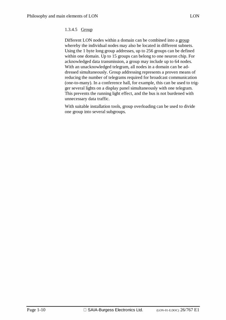
1.3.4.5 Group
Different LON nodes within a domain can be combined into a groupwhereby the individual nodes may also be located in different subnets.Using the 1 byte long group addresses, up to 256 groups can be definedwithin one domain. Up to 15 groups can belong to one neuron chip. Foracknowledged data transmission, a group may include up to 64 nodes.With an unacknowledged telegram, all nodes in a domain can be ad-dressed simultaneously. Group addressing represents a proven means ofreducing the number of telegrams required for broadcast communication(one-to-many). In a conference hall, for example, this can be used to trig-ger several lights on a display panel simultaneously with one telegram.This prevents the running light effect, and the bus is not burdened withunnecessary data traffic.
With suitable installation tools, group overloading can be used to divideone group into several subgroups.
LON Philosophy and main elements of LON
26/767 E1 (LON-01-E.DOC) SAIA-Burgess Electronics Ltd. Page 1-11
1.3.5 Addressing modes
According to the possible address allocations, various addressing modescan be used. In each case, the LonTalk address field designates thesender address and the destination address of a LonTalk telegram. TheLonTalk protocol defines hierarchical addressing with domain, subnet,and node addresses. For talking to several LON nodes simultaneously,there is also domain and group addressing. A LON node can therefore becommunicated with at various addresses.
In total there are five addressing modes. The complete address field con-sists of the domain address (0, 1, 3 or 6 bytes), the destination addressand the sender’s address. Depending on addressing mode, the destinationaddress contains the neuron ID (6 bytes), group address (1 byte) or Sub-net and node address (combined 2 bytes). The sender’s address alwaysconsists of the subnet and node address of the transmitting node.
Via its neuron ID, a LON node can be addressed specifically at any time.In contrast, the address assigned during the installation phase can changein the lifetime of a node. Because of the length of the neuron ID (6 bytes)this should only be used during installation and configuration of a LONnetwork. If a node has to be exchanged, the newly inserted node simplyreceives the same address information as the old one. Its communicationspartners in the network remain, however, unchanged.
A domain is identified by its domain ID (0, 1, 3 or 6 bytes). If the neuronID of a LON node belonging to the domain is used for a 6-byte long do-main ID, the uniqueness of the domain ID is thereby guaranteed. In aLON system, where there can be no possibility of intersection betweendifferent areas, the domain ID should be dropped in the interests ofshorter telegram length.
Depending on the addressing mode, the length of a LonTalk addressranges from 3 to 9 bytes. Added to this is the length of the domain ID(0...6 bytes). The address information contained in a LonTalk telegramtherefore ranges from 3 bytes for group addressing to 15 bytes for ad-dressing via the neuron ID with a 6-byte domain address.
Philosophy and main elements of LON LON
Page 1-12 SAIA-Burgess Electronics Ltd. (LON-01-E.DOC) 26/767 E1
1.3.6 Explicit messages
All LON telegrams are explicit messages, i.e. a “data train” that finds itsway through the network to the correct destination node. The driver ofthe locomotive is the address, automatically sets the points in the net-work. As with the Internet, this enables data to be transmitted in any de-sired form (layer 6). Explicit messages are used by many manufacturersto control their proprietary systems. The address of the receiver can ei-ther be specified by the programmer or configured in EPROM.
Advantages:
• more efficient than network variables
Disadvantages:
• without precise knowledge of the message structure, connection is notpossible (i.e. connection to nodes from different manufactures is onlypossible with difficulty)
• require greater programming expense → more code
However, on layer 7 LON offers a special explicit message that enablesthe direct linking of program variables with the network. The followingsection deals with this form of message.
LON Philosophy and main elements of LON
26/767 E1 (LON-01-E.DOC) SAIA-Burgess Electronics Ltd. Page 1-13
1.3.7 Network variables
The network variables are the basis of an important and, in this form,unique feature of LonWorks: interoperability. It means the smooth, com-bined action following simple rules of LonWorks based products fromdifferent manufacturers, e.g. a gas burner, a temperature sensor in theboiler, a circulation pump, a single-room controller with several roomtemperature sensors and heating valves. Due to the many and various in-terconnections of production and installation technology among manu-facturers, system planners and installation companies, interoperability isan important prerequisite for the spread of LonWorks throughout indus-try and building automation. Otherwise expressed, LonWorks enablescomplex systems to be built up as if they came from a single source.LonWorks therefore steadily but inexorably evolves into a de facto stan-dard.
Communications principle:
• Network Variables (NV):Variables which create connections between two or more nodes.Variable linking can be selected to occur either when program-ming the application, during the final test on the device, on-siteat the installation or while the network is running.
• To create connections between nodes from different manufactur-ers, standard network variables (SNVT) and standard con-figuration data (SCPTS) are used.
SNVTs “bind” themselves. This means that, from an entry in local mem-ory, an SNVT knows which nodes expect data from it. Consequently, thisdata is transmitted whenever its value changes.
Philosophy and main elements of LON LON
Page 1-14 SAIA-Burgess Electronics Ltd. (LON-01-E.DOC) 26/767 E1
1.3.8 Configuration and network management
At the logical level, network variables can be used between individualneuron nodes to establish many communications connections (so-calledbindings). This is generally carried out with the help of an installation tool(handheld device, PC under DOS or Windows) in the field, with corre-sponding entries being made in the EEPROMs of individual nodes. How-ever, in some cases (e.g. in a machine controller) all nodes are predefinedwith all communications relationships.
Several scenarios are offered for commissioning a LON system. De-pending on the status of the LON nodes to be installed, the communica-tions relationships and the application program must be transferred to thenodes. The simplest option for small systems is the plug-and-play instal-lation of preconfigured nodes by the user.
Larger systems are commissioned with the help of a network manage-ment node (NMN, handheld device or PC). An NMN can search a LONsystem for newly added nodes and configure them, load an applicationprogram into the node, start, stop and reset it. Moreover, it can read thecommunications statistics carried by the node, configure routers and es-tablish the structure of a running LON system. During installation a cor-respondence must be produced between the physical position of eachLON node. For this the installer can request a node with the ... command,execute a special function (e.g. lamp 1 flashes once) to identify or locateit. He then uses the NMN to produce logical connections to other nodes.
Another scenario provides for the creation of a list of the neuron IDs andphysical positions (including functions) of LON nodes. The NMN thenassigns the required communications relationships to the nodes and pos-sibly supplies them with missing application program. To simplify instal-lation, the neuron chips offer a node identification string of 8 bytes inlength.

LON Philosophy and main elements of LON
26/767 E1 (LON-01-E.DOC) SAIA-Burgess Electronics Ltd. Page 1-15
1.4 Nodes
1.4.1 NEURON -based nodes
The NEURON chip is the heart of LonWorks technology. These exist intwo versions: single chip (type 3120) for simple applications and a chipwith up to 64 kByte of external memory (type 3150) for complex appli-cations.
Common to both is the possession of 3 CPUs each. Two of these are ex-clusively occupied with processing message telegrams across the commu-nications ports, whereas the third CPU processes the user program. Dataexchange between CPUs occurs across the RAM data buffer. Built-inROM memory contains firmware for the event-controlled operating sys-tem, the LonTalk protocol and a library currently holding 34 I/O modelsthat enable digital inputs and outputs of any complexity to be processedat the pins of the application I/O block. In addition, the 3120 chip hassufficient EPROM to store the application program and the network con-figuration parameters. This makes it possible to integrate a virgin nodeinto the network at any time and to download its specific application viathe network. Further important features are two fast clock & timer cir-cuits as a basis for timing I/O functions and a 48-bit serial number whichis unambiguous worldwide. This is not only responsible for installationpurposes, but can also be useful for assigning ident numbers to the in-house product database.
MediaAccess
CPU
NetworkCPU
E2PROM512Bytes
RAM1KBytes/2KBytes(3150)
CommunicationPort, 1,25MBit/s
8-Bit Data Bus
16-Bit Address Bus
Timing & Control
Con-trol
Clock+Timers
I/O 0 .............................I/O 10 CP 0......CP 4Service
Reset
Vss6
6
4
Housing: SO-32 (3120), PQFP-64 (3150)
Appli-cationCPU*
FirmwareROM
10KBytes(3120)
Application I/O Block2x16-Bit counter, 20mA-Driver, Pull-ups, SPI, Uart,
Parallel I/O, PWM, Dual slope A/D, Quadratur-Dec..
External bus interface 58KBytes (3150)
Clock(10 MHz)
Vcc 5V
400'000cmds/s,program-mable in"Neuron-C"
*
Figure 8: NEURON chip
Philosophy and main elements of LON LON
Page 1-16 SAIA-Burgess Electronics Ltd. (LON-01-E.DOC) 26/767 E1
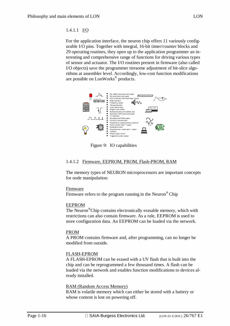
1.4.1.1 I/O
For the application interface, the neuron chip offers 11 variously config-urable I/O pins. Together with integral, 16-bit timer/counter blocks and29 operating routines, they open up to the application programmer an in-teresting and comprehensive range of functions for driving various typesof sensor and actuator. The I/O routines present in firmware (also calledI/O objects) save the programmer tiresome adjustment of bit-slice algo-rithms at assembler level. Accordingly, low-cost function modificationsare possible on LonWorks® products.
Bit, nibble, byte input and output Bit serial input and output A/D conversion with dual-slope control Edge log input Frequency output Infrared decoder Level detect input Magnet card reader Multipexed data and address bus Neurowire (SPI) input and output I2C-Interface Monoflop and PWM output On-time or period input Parallel bus coupling (active, passive) Pulse counter input + output Quadrature input Asynchronous, serial input + output Totalizer Phase-angle control Triggered counter output
1 0 0 01 1 1
CREDIT CARD
1 2 34 5 67 8 9
0# *
1KHz
200ns
+
-E C H E L O N
Figure 9: IO capabilities
1.4.1.2 Firmware, EEPROM, PROM, Flash-PROM, RAM
The memory types of NEURON microprocessors are important conceptsfor node manipulation:
FirmwareFirmware refers to the program running in the Neuron® Chip
EEPROMThe Neuron®Chip contains electronically erasable memory, which withrestrictions can also contain firmware. As a rule, EEPROM is used tostore configuration data. An EEPROM can be loaded via the network.
PROMA PROM contains firmware and, after programming, can no longer bemodified from outside.
FLASH-EPROMA FLASH-EPROM can be erased with a UV flash that is built into thechip and can be reprogrammed a few thousand times. A flash can beloaded via the network and enables function modifications to devices al-ready installed.
RAM (Random Access Memory)RAM is volatile memory which can either be stored with a battery orwhose content is lost on powering off.
LON Philosophy and main elements of LON
26/767 E1 (LON-01-E.DOC) SAIA-Burgess Electronics Ltd. Page 1-17
1.4.1.3 Service
The service pin is a special neuron chip connection. It represents a naturalaid during configuration, commissioning and maintenance of the networknode to which the neuron chip belongs. If a tracer is connected, therebygrounding the service pin, the latter (or preferably the neuron firmware) is-sues a special network management telegram, advising all nodes in thenetwork of its unique 48-bit serial number (neuron chip ID) among otherthings. This information can be used by a network manager for assigningthe logical network address of the node during installation and for its sub-sequent configuration.
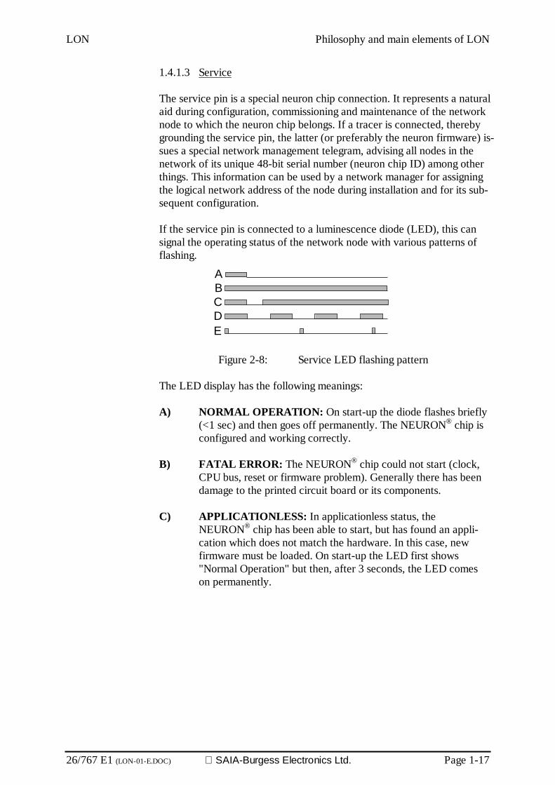
If the service pin is connected to a luminescence diode (LED), this cansignal the operating status of the network node with various patterns offlashing.
Figure 2-8: Service LED flashing pattern
The LED display has the following meanings:
A) NORMAL OPERATION: On start-up the diode flashes briefly(<1 sec) and then goes off permanently. The NEURON® chip isconfigured and working correctly.
B) FATAL ERROR: The NEURON® chip could not start (clock,CPU bus, reset or firmware problem). Generally there has beendamage to the printed circuit board or its components.
C) APPLICATIONLESS: In applicationless status, theNEURON® chip has been able to start, but has found an appli-cation which does not match the hardware. In this case, newfirmware must be loaded. On start-up the LED first shows"Normal Operation" but then, after 3 seconds, the LED comeson permanently.
A
DCB
E

Philosophy and main elements of LON LON
Page 1-18 SAIA-Burgess Electronics Ltd. (LON-01-E.DOC) 26/767 E1
D) UNCONFIGURED: For an unconfigured node, the LEDflashes at a frequency of 1 Hz. The hardware works correctly,but has not yet started the user program. The node must now beconfigured (assignment of a logical address), to convert to"Normal Operation" mode.
E) WATCHDOGING: The internal watchdog of the NEURON®
chip restarts the chip every 750 ms, which is indicated by a briefblink of the LED. The node might actually start up normally, butfinds a running time error. Causes of the error can be non-functioning parallel ports or unsynchronized bit serial ports.
Neuron-Chip firmware starts up whenever the service pin is activated,regardless of whether the node already carries a user program or whethernetwork configuration has already occurred.
The service pin is subject to control by the software (firmware), if thelatter is connected to the I/O pin. The main program of the network proc-essor (processor 2 on the neuron chip) regularly polls the service pinabout any telegram sent or received. The service pin can even be ac-cessed from the user program. However, when writing the user programthe programmer must consider certain differences in the logical organiza-tion of the service pin, which depend on processor type and firmwareversion.
1.4.1.4 Neuron-C
Neuron chips are programmed in "Neuron-C". As a rule, the nodes can bereloaded via the network; the whole network thereby becomes a freelyprogrammable application.
It enables the functionality of an entire LON system to be described inthe form of a C program, whose individual procedures communicate witheach other via network variables. For the programmer it is of secondaryimportance that individual subroutines should only run on various micro-controllers that, physically, are connected to each other only by a bus.
Among the suppliers of LonTech services, companies are found that canefficiently realize special applications.

LON Philosophy and main elements of LON
26/767 E1 (LON-01-E.DOC) SAIA-Burgess Electronics Ltd. Page 1-19
1.4.1.5 Configurability
NEURON nodes have a data structure that permits linking with theirnetwork partners. This data structure is generally administered by an in-stallation tool that takes over control of system functions. Two domaintables serve to store domain membership. In addition, 64 selectors can beentered for network variables, which enable entry of the bindings. For thenode to know where it can send outgoing data, it has 14 address tables atits disposal.
domain 0domain 1
adr_tab 0
adr_tab 14
nv_tab 0
nv_tab 64
Addresses for outgointtelegrams
Group addresses for outgoingand incoming telegrams
Group entrySelector
Address entry
Selector
Selector
Group entry
Figure 9: Configuration data of a NEURON
If an output variable now receives a new value, the program looks in"nv_tab" to find which selector has been entered and which address tableto work with. The address table in turn contains the information aboutwhich domain should be used. In this way the address of the telegram isput together. A NEURON can therefore address mas. 14 other nodes di-rectly. If group addresses are used, a maximum of 14 groups can beserved, whereby incoming group messages must also be entered in theaddress table. However, group tables can use several selectors, so that anode can be linked to more than 14 recipients.

Philosophy and main elements of LON LON
Page 1-20 SAIA-Burgess Electronics Ltd. (LON-01-E.DOC) 26/767 E1
1.4.2 Single chip processor 3120
The single chip 3120 is used for low-cost modules with limited functions,as its data memory is very limited. Programs can be loaded into theEEPROM via the bus.
3120CPUs 3EEPROM bytes 512RAM bytes 1 024ROM bytes (firmware) 10 240External Memory Interface No16-bit Timer/Counter 2Watchdog-Timer YesPackage SOICPins 32
1.4.3 Multiple chip processor 3150
The 3150 enables control of an external data bus and is therefore suitablefor more complicated tasks. Regarding its processor capacity availablefor the application, the 3150 comparable to a 68HC11 or 80C535.
3150
CPUs 3EEPROM bytes 512RAM bytes 2 048ROM bytes (firmware) 0External Memory Interface Yes16-bit Timer/Counter 2Watchdog-Timer YesPackage PQFPPins 64
1.4.4 Open protocol implementations
At present the LonTalk protocol is being integrated onto Motorola micro-processors. The first release was planned for autumn 1998.

LON Philosophy and main elements of LON
26/767 E1 (LON-01-E.DOC) SAIA-Burgess Electronics Ltd. Page 1-21
1.4.5 MIP (Micro Processor Interface Program)
To enable LonTalk to be projected onto more powerful processors, a par-allel port to other processor systems has been implemented on theNEURON chip. This port is controlled by a link layer and an applicationmessage layer protocol. It enables full access to the LonTalk protocol bythe microprocessor coupled to it.
MIP nodes now have no limits regarding processor power. One MIP canprocess 4096 selector entries, but the limitation regarding the 15 addressand 2 domain tables remains in force.
For the system integrator, the behaviour of an MIP based node is not sig-nificantly different. It just offers more variables and higher performance.
1.4.6 HOST node (NMN Network Management Node)
Host nodes are nodes that can also take over network management func-tions. HOST nodes manage and connect other nodes.
Host nodes have non-volatile memory (EEPROM, harddisk) and canmanage 4096 selectors plus however many addresses, as the host nodeassigns the entries to the nodes themselves. The integral installation toolon the host node decides on the assignment of group or subnet/node ad-dresses and can therefore adapt entries to requirements.
However, the installation tool must make do with 15 groups for messagesto be received, although per address table it can assign several selectorsto the same group.
In the conventional architecture of a LON bus system, it is only possibleto work with a single host per installation, which makes the integration oflarge installations difficult.
The Lon Network Service architecture (LNS) allows several host nodes,which among themselves coordinate entries into configuration data usingthe client-server principle.

Philosophy and main elements of LON LON
Page 1-22 SAIA-Burgess Electronics Ltd. (LON-01-E.DOC) 26/767 E1
1.5 LonWorks transceivers
Transceivers are the major advantage of LonWorks technology. Withthese components, it is possible for producers to access efficiently agread diversity of media.
Based on the various transceiver technologies, corresponding bus topolo-gies can be formed. Figure 11 demonstrates possible topologies:
Traditional bus: e.g RS485
Bus with stub cables:FTT-10, TP78 and TP1250 (Transformer)
Ring: link power LPT (with supply)and Free Topology FTT (Transformer)
Star: link power LPT (with supply)and Free Topology FTT (Transformer)
Free topology: link power LPT (withsupply) and Free Topology FTT (Transformer)
Termination
Terminationor centralsupply
Figure 11: LonWorks bus topologies
1.5.1 Twisted Pair TP 78
For the conventional bus topology, it is possible to work with the twistedpair transeiver for 78.1 kBit/s or 1.25 MBit/s. Isolating the bus with atransformer guarantees high interference immunity.
TP-78Distance: 1400m, terminated both endsNodes per channel: 64Stub: Maximum 3 MSpecial: At below-zero temperatures, only 44 nodes
per channelZero Voltage range: +230 V..230 V rms

LON Philosophy and main elements of LON
26/767 E1 (LON-01-E.DOC) SAIA-Burgess Electronics Ltd. Page 1-23
1.5.2 Free Topolgy FTT-10
Without doubt, the FTT-10 is the favourite transceiver, which will gainacceptance as the standard. Directing a fieldbus in free topology still re-mains at the current time a record technological achievement. Particu-larly outstanding is the simple integration of these components into prod-ucts, with the design guidelines practically guaranteeing successful CEcertification.
FTT-10Distance: 2700m, terminated both ends and in bus to-
pology400 m in free topology and terminated at oneend
Nodes per channel: 64Zero voltage range. +230 V..230 V rms
1.5.3 RS-485
The RS-485 is still the cheapest solution, but only offers (depending onspecification type) a zero voltage range of -7 to +12V. Especially suitablefor the smaller installations.
Type Medium kBit/s Length/topology/notes Total nodesTP-RS485 Twisted
2-wire line39 to625
1200m at 39kBit/s, Bus,with or without galv. Isolat.
32 perBus segment
TPT/XF-78Trafo
Twisted2-wire line
78 1400m, bus with 3m stubCables, isolation 277V RMS
64 perBus segment
TPT/XF-1250Trafo
Twisted2-wire line
1250 130m, bus with 0,3m stubCables, isolation 277V RMS
64 perBus segment
FTT-10Trafo
Twisted2-wire line
78 2700m as bus, 500m with freetopology, isolation 277V RMS
64 perBus segment
LPT-10Link Power
Twisted2-wire line
78 500m, free topology, 42V DC,5V / 100mA per node
32 -128 perBus segment
PLT-20Power Line
230 VAC-or DC
4,8 50m-5km, BPSK modulationCenelec Band C, 132.5kHz
Net depend.
PLT-30Power Line
230 VAC-or DC
2 50m-5km, Spread SpectrumCenelec Band A, 9-95kHz
Net depend.
Table 1: Overview of LonWorks transceivers
Philosophy and main elements of LON LON
Page 1-24 SAIA-Burgess Electronics Ltd. (LON-01-E.DOC) 26/767 E1
1.5.4 Link Power
When link-power transceivers are used, data and supply energy (48 V)flow together with polarity protection through a twisted-pair line. An in-tegral mains supply circuit in the transceiver can supply the LON node(including application circuit) with up to 100mA at +5 V. This involves acentral power-pack supplying a bus segment up to 320m long. The extentof the bus can be increased by linking several link-power segments.When laying the bus line, the installer need not bother about any maxi-mum lengths of bus branches or other topological restrictions, as theLPT-10 transceiver allows a free choice of topology (star, ring, mul-tidrop). The same thought was also the trigger for developing the FTT-10,the Free Topology Transceiver. Unlike the LPT-10, it means that eachLON nodes possesses its own power supply. Both version can also bemixed.
1.5.5 Power Line
Generations of development engineers have already examined the subjectof "data transmission via the supply main". As a medium, the supply mainhas an enormous advantage. It is already in existence in residential andfunctional buildings alike, making unnecessary the ripping open of walls tolay bus lines. At the same time the supply main, designed for energytransmission, has an equally large disadvantage as a data transmission me-dium: the characteristics of the line differ from place to place and can also,depending on the type and number of consumers connected, change fromone moment to the next.
Switched power-packs, electric motors or dimmers are widespread sourcesof interference, distorting data signals modulated to the supply main some-times beyond recognition. By making full use of the available transmissionband width, by choosing suitable modulation procedures and with appro-priate signal filtering, the supply main can however still be made useful forthe transmission of information. LonWorks offers three power-line trans-ceiver modules for this.
The frequency bands approved by the relevant authorities for data trans-mission via the supply main by differ between North America, Japan andEurope. In America and Japan the frequency range 0 to 500 kHz hasbeen released. This large band width allows the spread-spectrum modula-tion procedure to be used. It involves broad-band transmission of the in-formation in a large frequency range. Interference, much of which is re-stricted to its band width, cannot therefore impair data transmission overthe whole frequency band. The power-line transceiver PLT-10, which isonly approved in the USA, works according to this procedure in the range100 kHz to 450 kHz and thereby achieves a net data rate of 10 kBit/s.
In Europe, CENELEC (Comité Européen de Normalisation Electrotech-nique; European Committee for Electrotechnical Standards) has only re-leased the frequency range to 150 kHz (start of long-wave radio) forcommunication on the supply main. This range is additionally subdivided

LON Philosophy and main elements of LON
26/767 E1 (LON-01-E.DOC) SAIA-Burgess Electronics Ltd. Page 1-25
into various bands. CENELEC band A (9 kHz to 95 kHz) is reserved fordata exchange by network operators (power supply and distribution com-panies). CENELEC band B (95 kHz to 125 kHz) is used for communica-tion without access protocol for end-user applications. CENELEC bandC (125 kHz to 140 kHz) carries protocol controlled data communicationsfor customer applications. The band A transceiver PLT-30 also uses thespread-spectrum procedure to achieve a data rate of 2 kBit/s in this fre-quency band. The narrow band C requires another modulation procedure.PLT-20 uses BPSK (Binary Phase Shift Keying), enabling this transceiverto achieve a data rate of 4 kBit/s.
To investigate the suitability of existing low-voltage networks (230 V) foruse as data communications media, Echelon provides the Power LineCommunications Analyzer (PCLA). This device allows a series of testswhich, apart from the telegram error rate, also give information on theanalogue transmission parameters (damping, noise and signal distortion)of the supply main. In addition, there is a PC-based test kit (PLE-30),which helps to establish a communications connection between two ormore PCs, testing the transmission and receipt of telegrams underchangeable transmission parameters.

Philosophy and main elements of LON LON
Page 1-26 SAIA-Burgess Electronics Ltd. (LON-01-E.DOC) 26/767 E1
1.5.6 Other transceivers
The following other transceivers are also available on the market:
• Intrinsically safe transceivers, 78kBit/s
• Radio 432MHz
• Fiber optic
• Infra red
• Coax
• Tf line
• Microwave
LON Philosophy and main elements of LON
26/767 E1 (LON-01-E.DOC) SAIA-Burgess Electronics Ltd. Page 1-27
1.6 LonWorks Tools
The fourth element, LonWorks Tools, comprises the development and in-stallation tools. These are used to develop nodes or for installation plan-ning and execution.
Within this introduction, only a list of the most popular tools will be in-cluded, as tools will be dealt with in a developer course or system inte-gration course. Further tools, mainly of importance for developers, arethe development tools for Neuron®-C and those for host applications. It ispossible to construct installations so that field compilers are used to sup-port each node with the appropriate source-code software and expand itvia the network with new programs. This capability is unique to field-bussystems, but is generally only provided if specially requested (disclosureof firmeware source code). However, at runtime-library level, transparentsoftware maintenance on all nodes is thoroughly normal.
Installation tools:• LonMaker• Helios• ICELAN-G• Alto• Response• Unilon• Pathfinder
There are two generations among installation tools, i.e. those built on thefirst Windows application interface: Helios, Icelan-G, Alto and Metravi-sion, plus the LNS/LCA (Lon Network Server/Lon Component Archi-tecture) tools LonMaker for Windows, Unilon, Response and Pathfinder.
Today it can be assumed for all commonly used installation tools that theinclusion of building plans and graphic display of node mounting points issupported.
The more recent LNS/LCA tools are built on modern standards for Win-dows 95 / NT workstations and allow object oriented design (Active-XOXC components) of control software and its node-specific functions.When choosing installation tools, it is necessary to ensure that deviceplug-ins are available for the selected hardware. This kind of plug-in pro-vides the system integrator with a graphical interface for setting node pa-rameters easily, which is embedded in the installation tool. Double-clicking on the node image opens the corresponding plug-in window.
Philosophy and main elements of LON LON
Page 1-28 SAIA-Burgess Electronics Ltd. (LON-01-E.DOC) 26/767 E1
As a rule, tools are marketed so that a fee is payable per installed node.This means that, for smaller installations, tools can be obtained within areasonable price scale.
The cost of system configuration in planning and time is frequently un-derestimated. Whereas with conventional installations, individual datapoints had to be connected with cable, with LonWorks® connection oc-curs with the tool. The cost of processing the information remains thesame. However, at first sight it is hard to see how this is the case, withfiles full of electrical diagrams.

LON The LONMARK Standard
26/767 E2 (LON-02-E.DOC) SAIA-Burgess Electronics Ltd. Page 2-1
2. The LonMark Standard
2.1 Physical Layer (Layer 1)
The LonMark physical layer assumes responsibility for transceiver speci-fication and has been defined for the following transceivers:
• TP-RS 485-39
• TP/XF-78
• TP/XF-1250
• TP/FT-10
• PL-10 (L-E)
• PL-20 (L-N)
• PL-20 (L-E)
• PL-30 (L-N)
• RF100
The LONMARK Standard LON
Page 2-2 SAIA-Burgess Electronics Ltd. (LON-02-E.DOC) 26/767 E2
2.2 Layer 2 - 6
In layers 2 and 4 only, LonMark defines the following additional mini-mum conditions:
• Layer 2: minimum quartz frequencies relative to transceiver
• Layer 4: minimum size of transaction buffer fixed at 66 bytes

LON The LONMARK Standard
26/767 E2 (LON-02-E.DOC) SAIA-Burgess Electronics Ltd. Page 2-3
2.3 Application Layer (Layer 7)
To ensure interoperability, network variables are combined as objectsthat, viewed logically, represent sensors, actuators and controller func-tions.
LonMark® has taken this job in hand and already defined more than onehundred SNVTs (Standard Network Variable Type) and SCPTs (StandardConfiguration Parameter Types), which guarantee the interoperability ofvariables in terms of meaning, priority and range.
Controller
SNVT_xxxSNVT_xxx
SNVT_xxx
Standard outputfeedback delay,
etc.
Mandatory networkvariables
Optional networkvariables
Configurationparameters
SNVT_preset SNVT_preset
Figure 12: Documentation of a node with LonMark objects
An SNVT is provided with a number that defines its type. In addition, in-formation relative to the SNVT is stored in the node and can be read fromit using the installation tools. This text information generally includes thevariable name, from which its function can be understood.
The following table shows an extract from LonMark’s SNVT definition.
Measurement Name Range No.Speed SNVT_speed
SNVT_speed_f
0..6553.5 m/sec in 0.1m/s-1E38..+1E38 m/s
34
39Sound level SNVT_sound -327.68...327.67 dB (0.01dB) 33
SNVTs can contain entire structures, for example, "SNVT_time_stamp"contains complete time information in years, months, days, hours, min-utes and seconds.
A current SNVT list can be found on LonMark’s homepage.
http://www.lonmark.org

The LONMARK Standard LON
Page 2-4 SAIA-Burgess Electronics Ltd. (LON-02-E.DOC) 26/767 E2
2.4 LonMark objects
2.4.1 Structure of a LonMark objectFor use on an interoperable network node there is the LonTalk protocol,which provides access to the network in the form of LonMark objects.These are marked with their type (via a number assigned by the LonMarkorganization), a set of network input and output variables and a set ofconfiguration parameters. The interoperability that the network standardstrives for is represented by LonMark objects in form and meaning. Thestructure illustrated in figure 4-5 is generally valid.
The object number marks its type; the name serves only to aid under-standing. The object always possesses one or more mandatory networkvariables and can also carry optional NVs. The input variables are illus-trated on the left of the diagram and output variables on the right. Bothtypes together are numbered through from 1 to n, with no differentiationrequired between input and output variables. Only SNVTs are used.
Configurations however, which can also be entered via NVs, carry thenumber of the appropriate configuration parameter (SCPT) from theSCPT list [8]. NV names must not exceed 11 characters in length, shouldcontain no underlines and should be written in lower-case (including thefirst letter of a word). Examples can be found in the following sections.
Figure 4-5: General structure of a LonMark object [5]
Object name and number
Mandatorynetwork variables( M )
nvx nvi YYYYYYSNVT_ZZZZ nvx nvo YYYYYY
SNVT_ZZZZ
Optionalnetwork variables( O )
nvx nvi YYYYYYSNVT_ZZZZ
nvx nvi YYYYYYSNVT_ZZZZ
nvxnvo YYYYYYSNVT_ZZZZ
Configurationproperties
Range freelyconfigurable
by manufacturernvx nvi YYYYYY
SNVT_ZZZZ nvx nvo YYYYYYSNVT_ZZZZ
Hardwareoutput
Hardwareinput
Networkvariables:inputs
Networkvariables:outputs

LON The LONMARK Standard
26/767 E2 (LON-02-E.DOC) SAIA-Burgess Electronics Ltd. Page 2-5
Names are given a leader string to indicate memory class and the direc-tion of transmission:
nvi ~ input variable stored in: RAMnvo ~ output variable RAMnci ~ configuration variable EEPROMnro ~ (read only) output variable ROM
The relationship to the user process is represented with an arrow above,for a hardware output, or below, for a hardware input. By stating pre-cisely these general details the different object types emerge, such asnode-objects, sensor-objects, HVAC-objects, etc.
The LONMARK Standard LON
Page 2-6 SAIA-Burgess Electronics Ltd. (LON-02-E.DOC) 26/767 E2
2.4.2 Node object
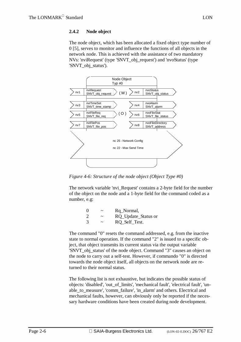
The node object, which has been allocated a fixed object type number of0 [5], serves to monitor and influence the functions of all objects in thenetwork node. This is achieved with the assistance of two mandatoryNVs: 'nviRequest' (type 'SNVT_obj_request') and 'nvoStatus' (type'SNVT_obj_status').
Figure 4-6: Structure of the node object (Object Type #0)
The network variable 'nvi_Request' contains a 2-byte field for the numberof the object on the node and a 1-byte field for the command coded as anumber, e.g:
0 ~ Rq_Normal,2 ~ RQ_Update_Status or3 ~ RQ_Self_Test.
The command "0" resets the command addressed, e.g. from the inactivestate to normal operation. If the command "2" is issued to a specific ob-ject, that object transmits its current status via the output variable'SNVT_obj_status' of the node object. Command "3" causes an object onthe node to carry out a self-test. However, if commando "0" is directedtowards the node object itself, all objects on the network node are re-turned to their normal status.
The following list is not exhaustive, but indicates the possible status ofobjects: 'disabled', 'out_of_limits', 'mechanical fault', 'electrical fault', 'un-able_to_measure', 'comm_failure', 'in_alarm' and others. Electrical andmechanical faults, however, can obviously only be reported if the neces-sary hardware conditions have been created during node development.
nv1 nviRequestSNVT_obj_request nv2 nvoStatus
SNVT_obj_status
nc 25 - Network Config
nc 22 - Max Send Time
Node ObjectTyp #0
nv3 nviTimeSetSNVT_time_stamp nv4 nvoAlarm
SNVT_alarm
nv5 nviFileReqSNVT_file_req nv6 nvoFileStat
SNVT_file_status
nv7nviFilePosSNVT_file_pos nv8
nvoFileDirectorySNVT_address
( O )
( M )
LON The LONMARK Standard
26/767 E2 (LON-02-E.DOC) SAIA-Burgess Electronics Ltd. Page 2-7
A full description of these interrelationships is given in the "LonMarkApplication Layer Interoperability Guidelines" [5]. The same also appliesfor optional NVs and configuration parameters.
The configuration parameter 'Max Send Time' defines the maximumwaiting time, after expiry of which the object automatically reports itsstatus via the network variable 'NVT_obj_status', without any previousNV-Update. This function is called a "heartbeat" and, like a heartbeat,shows that the object is "still alive". The Max Send Time configurationparameter carries number 22 from the SCPT master list [8].

The LONMARK Standard LON
Page 2-8 SAIA-Burgess Electronics Ltd. (LON-02-E.DOC) 26/767 E2
2.4.3 Sensor objects
Sensor objects are general LonMark objects for use with any choice ofsensor for whatever physical measurements (such as temperature, pres-sure, humidity) and for the digital values of detectors and switches.
Data can be transmitted directly across the output network variable 'nvo-Value' (type 'SNVT_xxx') to an actuator or controller node. There are twotypes of sensor object: the 'Open Loop Sensor Object' (object type #1)and the 'Closed Loop Sensor Object' (object type #2). They are differen-tiated by the respective absence and presence of feedback NVs in theobject. Figure 4-7 shows the structure of a sensor object without feed-back.
The measurement transmitted via the NV 'nvoValue' can be converted tothe correct physical dimensions by the part of the user program that rec-ords measurements. Any necessary linearization can also take placethere. It is equally possible to carry out conversion and linearization ofraw measurements via the 'Translation Table X' and 'Translation Table Y'configuration parameters
Although the SNVTs used have a minimum and maximum value, if re-quired the value range can also be limited using the 'Min Range' and 'MaxRange' configuration parameters. A suitable choice of 'Send on Delta' con-figuration parameter is recommended, which defines the size of anychange in sensor value which, only when it is reached, will trigger thetransmission of an NV-Update. The "heartbeat" function is used by the pa-rameter specification for 'Max Send Time'. On the other hand, the updaterate should also be limited by specifying a value for 'Min Send Time'. De-fault values are fixed depending on the bit rate of the transmission me-dium, i.e.: 1 s for 1.25 Mbit/s and 60 s for a bit rate of 2 kbit/s.
Figure 4-7: Structure of the Open Loop Sensor Object (Object Type #1)Open Loop SensorTyp #1
( O )
( M ) nv1nvoValueSNVT_xxxx
nv3nvoRawHwDataSNVT_count
nv4nvoPresetSNVT_preset
nv2nviPresetFbSNVT_preset
nc 17 - Location Labelnc 18 - Gainnc 26 - Offset.....

LON The LONMARK Standard
26/767 E2 (LON-02-E.DOC) SAIA-Burgess Electronics Ltd. Page 2-9
The sensor object with feedback (Figure 4-8) is suitable for applicationswhere any combination of many sensors must work together with manyactuators, or many sensors with one actuator, or one sensor with manyactuators. In all final positions the same information must be present. Forexample, this is the case when a lighting system can be turned on or offfrom various points and no visual contact is given. Figure 4-8 illustrates theessential difference compared with the open-loop sensor object: the addi-tional NV 'nviValueFb' (Fb ~ Feedback).
Figure 4-8: Structure of the Closed Loop Sensor Object, extract(Object Type #2)
Two typical methods exist for coupling between closed-loop sensor ob-jects and the corresponding actuator objects (Figure 4-9). Method 1 feedsthe output variable of the actuator object 'nvoValueFb' back to the'nviValueFb' input of the sensor object. However, rather than returningthe current actuator status, the value specified via 'nviValue' is reported.With the second method, the 'nvoValue' variables of sensor objects arefed back to the 'nviValueFb' inputs of sensor objects. This method in-volves less load on the network and works with shorter delay times.
Figure 4-9: Coupling methods between sensor and actuator objects withfeedback [6]
Closed Loop SensorTyp #2
( O )
( M ) nv2 nvoValueSNVT_xxxx
nv4 nvoRawHwDataSNVT_count
nv5nvoPresetSNVT_preset
nv3 nviPresetFbSNVT_preset
nc 17 - Location Labelnc 18 - Gainnc 26 - Offset.....
nv1 nviValueFBSNVT_xxxx
nvoValuenviValueFb
nvoValuenviValueFb nvoValueFbnviValue
Method 1nvoValuenviValueFb
nvoValuenviValueFb nvoValueFbnviValue
Method 2

The LONMARK Standard LON
Page 2-10 SAIA-Burgess Electronics Ltd. (LON-02-E.DOC) 26/767 E2
2.4.4 Actuator objects
The actuator objects (Open and Closed Loop Actuator Objects) carryobject type numbers 3 and 4. These are also defined as general objectsand can therefore equally be used in motor control units, such as fordriving valves or in completely different servo components. Figure 4-10shows the structure of an actuator object with feedback. The only thingthat differentiates it from the actuator object without feedback is the ad-ditional use of the NV 'nvoValueFb' and configuration parameter no. 15 -input 'Value Feedback Delay'. Feedback is used for synchronization be-tween actual and desired values.
Figure 4-10: Structure of Closed Loop Actuator Object (Object Type # 4)
Closed Loop ActuatorTyp #4
( O )
( M ) nv2 nvoValueFbSNVT_xxxx
nv4 nvoActPosnFbSNVT_count
nv5nvoPresetSNVT_preset
nv3 nviPresetFbSNVT_preset
nc 17 - Location Labelnc 8 - Drive Timenc 21 - Max Receive Time.....
nv1 nviValueSNVT_xxxx

LON The LONMARK Standard
26/767 E2 (LON-02-E.DOC) SAIA-Burgess Electronics Ltd. Page 2-11
2.4.5 Controller object
It is exceptional for an application to make do with sensor and actuatorobjects alone. The processing algorithms for sensor data are, in practice,more complex than the direct translation of a new sensor value into anactuator response. Even comparing an actual temperature value with atemperature setpoint demands a complex processing algorithm. If theactuator has to minimize the difference by exerting influence on a heater,this presents a classic instance of a controller. The controller object is de-fined for this and other potential applications (Figure 4-11).
As a generic object, the controller object has any number of network in-put and network output variables which, for ease of understanding,should be grouped into send variables and receive variables. This resultsin the creation (conceptually) on the controller object of a transmittingpart and a receiving part. The transmitting part’s NVs are connected withthe corresponding NVs of an actuator object and the receiving part’s NVswith the corresponding NVs of a sensor object (Figure 4-12). The NV'nviValueFb' is used in combination with closed loop actuator objects.The NV 'nvoValueFb' is only used in combination with closed loop sensorobjects and is therefore updated immediately when a new value is re-ceived via the NV 'nviValue'.
Figure 4-11: Structure of the controller object
Controller ObjectType #5
nvnvoValueSNVT_xxxx
According to application
nvnviValueFbSNVT_xxxx
Transmitter
nvnvoValueFbSNVT_xxxxnv
nviValueSNVT_xxxx
Receiver

The LONMARK Standard LON
Page 2-12 SAIA-Burgess Electronics Ltd. (LON-02-E.DOC) 26/767 E2
By assigning a function profile, a generic LonMark object becomes anapplication-specific object. If it is of interest for a large number of appli-cations, this can be certified as a LonMark object. In Figure 4-12 the stillunspecified configuration parameters are chosen on the one hand withreference to the sensor objects and actuator objects used, while on theother hand they must be controller-specific. So, if it is to be used as a PIDcontroller, the controller object requires the control parameters: propor-tional range, reset time, rate time, and a value for the sampling rate.

LON The LONMARK Standard
26/767 E2 (LON-02-E.DOC) SAIA-Burgess Electronics Ltd. Page 2-13
2.4.6 Function profiles
From the basic objects, function profiles have been derived that are tai-lor-made for specific applications. These function profiles are objects de-rived (inherited) from the basic classes, where the LonMark objects cor-respond to the basic classes and the function profiles form the sub-classesderived from them.
This architecture allows us to construct object-oriented networks and tomap them accordingly onto master computers to form a configurablecontrol system.
The following function profiles have been defined (as of 6.6.99):
LonMark designation
GenericAnalogue InputAnalogue Output
SensorsLight SensorPressure SensorTemperature SensorRelative Humidity SensorOccupancy SensorCO2 SensorAir Velocity Sensor
Light ControlLamp ActuatorConstant Light ControllerOccupancy Controller
Room ControlSwitchScene PanelScene ControllerPartition Wall Controller
Time controlReal Time KeeperReal Time Based Scheduler
Motor ControlVariable Speed Motor Drive
The LONMARK Standard LON
Page 2-14 SAIA-Burgess Electronics Ltd. (LON-02-E.DOC) 26/767 E2
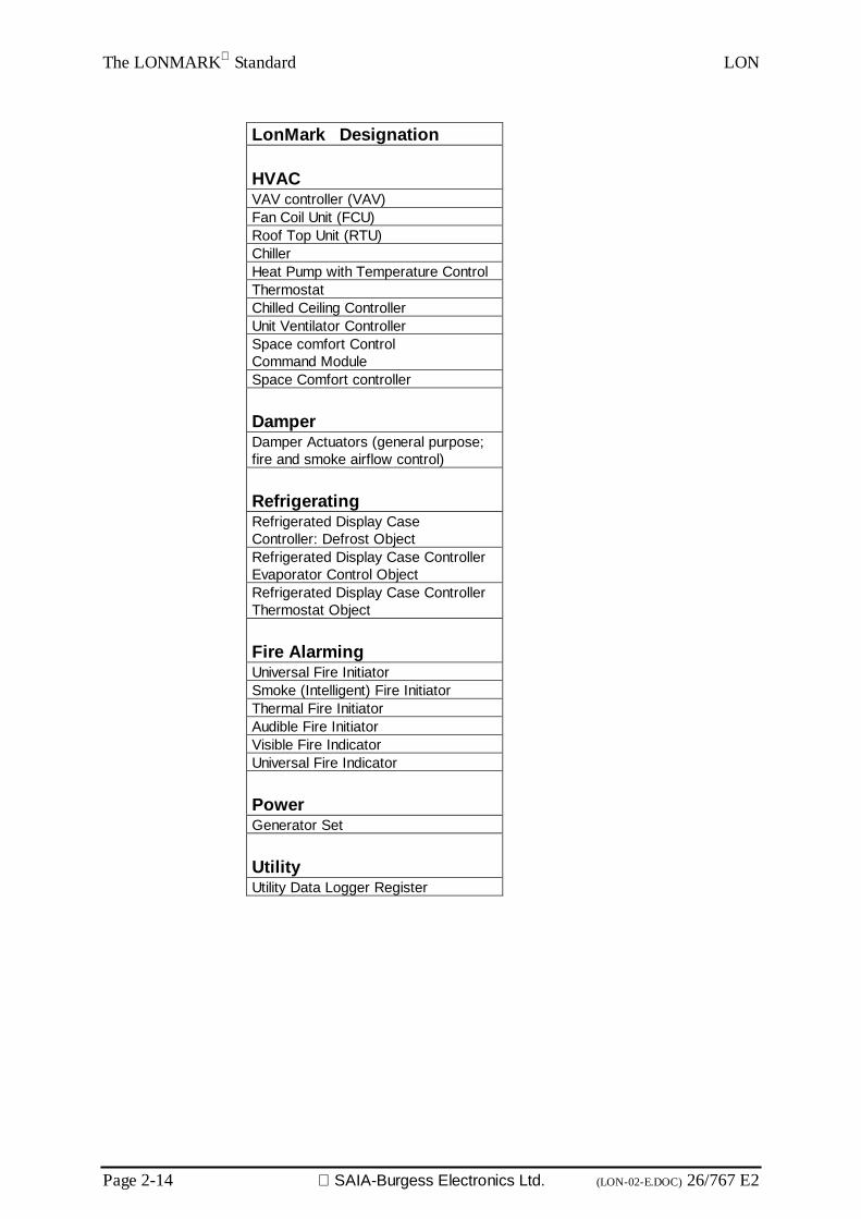
LonMark Designation
HVACVAV controller (VAV)Fan Coil Unit (FCU)Roof Top Unit (RTU)ChillerHeat Pump with Temperature ControlThermostatChilled Ceiling ControllerUnit Ventilator ControllerSpace comfort ControlCommand ModuleSpace Comfort controller
DamperDamper Actuators (general purpose;fire and smoke airflow control)
RefrigeratingRefrigerated Display CaseController: Defrost ObjectRefrigerated Display Case ControllerEvaporator Control ObjectRefrigerated Display Case ControllerThermostat Object
Fire AlarmingUniversal Fire InitiatorSmoke (Intelligent) Fire InitiatorThermal Fire InitiatorAudible Fire InitiatorVisible Fire IndicatorUniversal Fire Indicator
PowerGenerator Set
UtilityUtility Data Logger Register

LON Components of a network
26/767 E2 (LON-03-E.DOC) SAIA-Burgess Electronics Ltd. Page 3-1
3. Components of a network
3.1 Nodes
Nodes were dealt with in section 2.2. This chapter refers to the informa-tion required by the system integrator to create documentation from theviewpoint of the system integrator.
To document nodes, the system integrator requires the following mini-mum information:• a good, comprehensive functional description• a so-called XIF file, which describes the network interface• a description of the electrical interface• any possible configuration descriptions• any possible program modifications and firmware versions
Components of a network LON
Page 3-2 SAIA-Burgess Electronics Ltd. (LON-03-E.DOC) 26/767 E2
3.2 Network organization components
Different channels are logically linked to each other by routers, whose twobus interfaces can be different or the same in physical nature. This is how,for example, a radio channel is connected to a two-wire section of line.
Routers consist of two mutually coupled NEURON chips that exchangetelegrams on Layer 6, mapping them to their relevant counterparts.Router algorithms are given by ECHELON and are equivalent on allproducts.
The generic term “router” includes coupling possibilities with differentrelaying methods (router algorithms):
3.2.1 Repeater
A repeater represents the simplest type of router. It passes all telegramson from one channel to the other. Apart from conversion between differ-ent transmission media, a repeater can also be used for analogue signalregeneration, thereby extending the length of the bus.
3.2.2 Bridges
The next level in router hierarchy is occupied by the bridge. A bridge is arouter with local intelligence. The bridge only relays telegrams within thesame domain, although two domains can be transmitted.
3.2.3 Learning Router
Learning routers observe communication on both connected network areasand deduce from it the network structure at domain and subnet level. Thelearning router then uses this knowledge to select which telegrams to con-vey from one channel to the other. Since a learning router cannot infer ex-isting group topologies from telegram communications, all telegrams arealways forwarded with group addresses.

LON Components of a network
26/767 E2 (LON-03-E.DOC) SAIA-Burgess Electronics Ltd. Page 3-3
3.2.4 Configured Router
In contrast, configured routers shift only selected telegrams, which havebeen entered in a routing table, between channels. The routing table iscreated with the aid of a network management tool. Since this tool alsodetermines the assignment of group addresses, a configured router canalso be programmed for the selective routing of group telegrams.
3.2.5 Why use routers?
Configured routers and learning routers belong to the class of intelligentrouters. They are more than just a means of connecting physically diversetransmission media. Due to their programming, they can also be used astelegram filters between channels of the same physical type: by routingonly selected telegrams on to other areas, they restrict telegram receptiontraffic to the local area. The rest of the LON system is therefore sparedcommunication in which it has no interest.

Components of a network LON
Page 3-4 SAIA-Burgess Electronics Ltd. (LON-03-E.DOC) 26/767 E2
3.3 System limits and tips for overcoming them
3.3.1 Domain restrictions
The addressing space on the LON bus is divided into different hierar-chies.
The so-called domains form the top level. The various domains are dif-ferentiated by a 0, 1, 3 or 6-byte long identification key, depending ontheir number.
Subnets comprise the second level from the top. Per domain a maximumof 255 subnets can be defined.
Finally, the third level is made up of individual nodes. Per subnet amaximum of 127 nodes can be defined. This results in a maximum of32385 nodes per domain.
If the number of domain nodes is exceeded, a second domain can be cre-ated and integrated by means of a gateway.
However, the maximum number of nodes in a domain is not as a rule thelimiting factor on a system.
3.3.2 Limited number of groups
This basic setting can produce a large number of grouping possibilities.For example, it enables a node to belong to two different domains at thesame time. In addition, various nodes can be defined as a group. Groupshave the advantage of significantly lower addressing requirements whenmessages are sent. Such groups may extend across different subnets. Perdomain a maximum of 256 groups can be defined. When operating underacknowledge-mode, a single group may comprise a maximum of 64nodes; under unacknowledged-mode the number of nodes per group isunlimited. A single node can belong to up to 15 groups.
The group total of 256,however, is a quite decisive limit when there are32385 possible nodes, and one which is practically always reached.Moreover, some installation tools are very liberal in handling the alloca-tion of groups.
The group limitation is bypassed by forming a global domain that containsall system-wide connections. Local connections are implemented in theirown domains, so that the group range does not have to be exceeded.

LON Components of a network
26/767 E2 (LON-03-E.DOC) SAIA-Burgess Electronics Ltd. Page 3-5
3.3.3 Limited number of channel parties
The total number of parties on a channel depends on the transceiver (c.f.2.3). If the total permissible number of nodes is reached (in most cases64) another channel can be separated off with a router.
Not all installation tools support the subsequent integration of routerswithin an existing network. It is therefore advisable to leave some capac-ity on channels unused, enabling any additions to be made that might be-come necessary at a later date.
3.3.4 Limited number of address tables
The limit of 15 address tables, which can only be exceeded for networkmanagement nodes, may lead to problems for tools from the first genera-tion. When choosing an installation tool it may in some cases be neces-sary to check whether "Group Overloading" is supported. All LNS toolssupport overloading and apply it automatically.
It involves dividing a group into several subgroups, which work with thegroup address but for which different selectors have been entered. Thismethod sets aside the disadvantage of address tables and the group re-striction, while retaining the full transparency of the system.
(See also section 8.2 for PCD applications).

Components of a network LON
Page 3-6 SAIA-Burgess Electronics Ltd. (LON-03-E.DOC) 26/767 E2
Notes

LON SAIA PCD devices for the LON network
26/767 E2 (LON-04.E.DOC) SAIA-Burgess Electronics Ltd. Page 4-1
4. SAIA PCD devices for the LON network4.1 LON host module PCD7.F80x
LON PCD Hardware PCD7.F804
Figure 1: View of PCD7.F80x
PCD Bus LON_ALON_B
Rx+/Tx+Rx-/Tx-
D160DisplayConnector
basicPCD7.F800
PCD7.F802+PCD7.F804
only
PCD7.F804only
NosyncLED
TrafficLED
ServiceLED
ServicePinSwitch
Figure 2: Logic diagram of PCD7.F80x

SAIA PCD devices for the LON network LON
Page 4-2 SAIA-Burgess Electronics Ltd (LON-04.E.DOC) 26/767 E2
The following LON interface modules are available:
Module FunctionPCD7.F800 LON interface module for PCD1.M120/M130
PCD2.M120PCD6.M300
PCD7.F802 LON interface module for PCD2.M120with interface 3, type RS485
PCD7.F804
*)
LON interface module for PCD1.M120 / M130PCD2.M120
with interface 3, type RS485 and connection for aPCD8.D160 terminal
*) Only available as PCD7.D165 terminal set.This set contains a plug-on ..D160 terminal with the additional RS 485communications interface on port 3 (not electrically isolated) and LONFTT10a interface.With the PCD1, port 3 is not supported and the recessed housing cover(order ref. 4'104'7338'0) must be used for the terminal.
Hardware and firmware versions that support the LON interfacemodule:
PCD system HW FWPCD1/2/6
FWPCD7.F80x
PG4 withconfigurator
Fromvers.
Modif. fromvers.
vers. Versions from
PCD1.M120/130 D 0 $63 LN0 SNET$2.1.017PCD2.M120 J 0 $73 LN0 SNET$2.1.017PCD2.M150 A 0 0A0 LN0 SNET$2.1.017PCD2.M250 J *) 0 $73 LN0 SNET$2.1.017PCD1.M137 A 0 V2.100 LN0 SNET32 2.1.204PCD2.M127 J 0 V2.100 LN0 SNET32 2.1.204PCD2.M157 K 1 V2.100 LN0 SNET32 2.1.204PCD2.M257 M 1 V2.100 LN0 SNET32 2.1.204
*) Version of PCD2.M15x board

LON SAIA PCD devices for the LON network
26/767 E2 (LON-04.E.DOC) SAIA-Burgess Electronics Ltd. Page 4-3
Variables supported
Variables Total number Amount of useful dataSNVT max. 4095 per PCD *) variableExplicit message max. 4095 per PCD *) to 50 bytes (LON MarkTM )
*) dependent on PCD memory
LON controller
The MC143150 LON controller from ECHELON is inserted onto thePCD7.F80x card. The firmware for the neuron is stored on a 32kEPROM with socket. The main memory consists of 256 kbit SRAM.
LON bus interface
The LON interface is equipped with an FTT_10A transceiver.The LON transceiver uses Manchester code for data transmission andcan therefore also be used for AC coupling. (Alternative equipment ver-sion of PCD7.F80x card)The PCD7.F80x card is delivered as an AC coupler as standard.
AC/DC mode
The layout of the module is such that LPT operation is possible (see alsosection 1.5.4). AC coupling is standard. The LON module is suppliedwith power directly through the PCD. In AC mode the 48 VDC used forthe LTP application are decoupled via two capacitors.
Transceiver specification
The rules for installing the FTT_10A transceiver should be noted (seeFTT_10A Transceiver Handbook, available on internet from ECHELON"www.echelon.com"). To protect the transceiver, spark gaps have beenused on the board.(Specification: VDE (EN132 400, IEC384-12) rel.2 UL1414 and CSAC22.2 No.0;1).
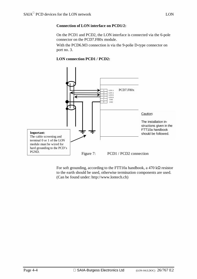
SAIA PCD devices for the LON network LON
Page 4-4 SAIA-Burgess Electronics Ltd (LON-04.E.DOC) 26/767 E2
Connection of LON interface on PCD1/2:
On the PCD1 and PCD2, the LON interface is connected via the 6-poleconnector on the PCD7.F80x module.With the PCD6.M3 connection is via the 9-polie D-type connector onport no. 3.
LON connection PCD1 / PCD2:
Figure 7: PCD1 / PCD2 connection
For soft grounding, according to the FTT10a handbook, a 470 kΩ resistorto the earth should be used, otherwise termination components are used.(Can be found under: http://www.lontech.ch)
543210
PCD7.F80xLON ALON ALON BLON BGNDGND
Important:The cable screening andterminal 0 or 1 of the LONmodule must be wired forhard grounding to the PCD’sPGND.
Caution:
The installation in-structions given in theFTT10a handbookshould be followed.

LON SAIA PCD devices for the LON network
26/767 E2 (LON-04.E.DOC) SAIA-Burgess Electronics Ltd. Page 4-5
Connection of RS485 interface on PCD2:
On a PCD2.M120, in addition to the LON interface, an RS485 interfaceis also available. This interface does not have potential isolation. The linetermination resistors can be activated with the jumper on the LON card.
Connection diagram of port 3, type RS485 on the PCD2:
Choice of line termination resistors:
Note: See also manual "Installation components for RS485networks"
Starting station Mid stations End station
PCD2.M..PCD2.M...mit
PCD7.F80x
PCD2.M...
31 32
37
36
36 37
37
36
Bus RS485
Max. segment length 1200m
max. 32 stations
Pull up330 Ohm
Line term.resistor150 Ohm
Pull down330 Ohm
+5V +5V
PCD2.M...
/RX - /TX
RX - TX
39383736353433323130
PCD2.M120/150
PCD7.F80x
PGNDRX-TX/RX-/TX
PGNDRX-TX/RX-/TXBus RS485
GND
39383736
34333231
Bus cable
Connector
ClosedOpen
Jumper for RS485 interface

SAIA PCD devices for the LON network LON
Page 4-6 SAIA-Burgess Electronics Ltd (LON-04.E.DOC) 26/767 E2
Meaning of connections:
Signal Meaning Connectorterminal
PCD7. F80x
Connectorterminal
PCD2. M120LON A 4 + 5 --LON B 2 + 3 --GND 0 + 1 --\RX / \TX -- 32RX / TX -- 31GND -- 30
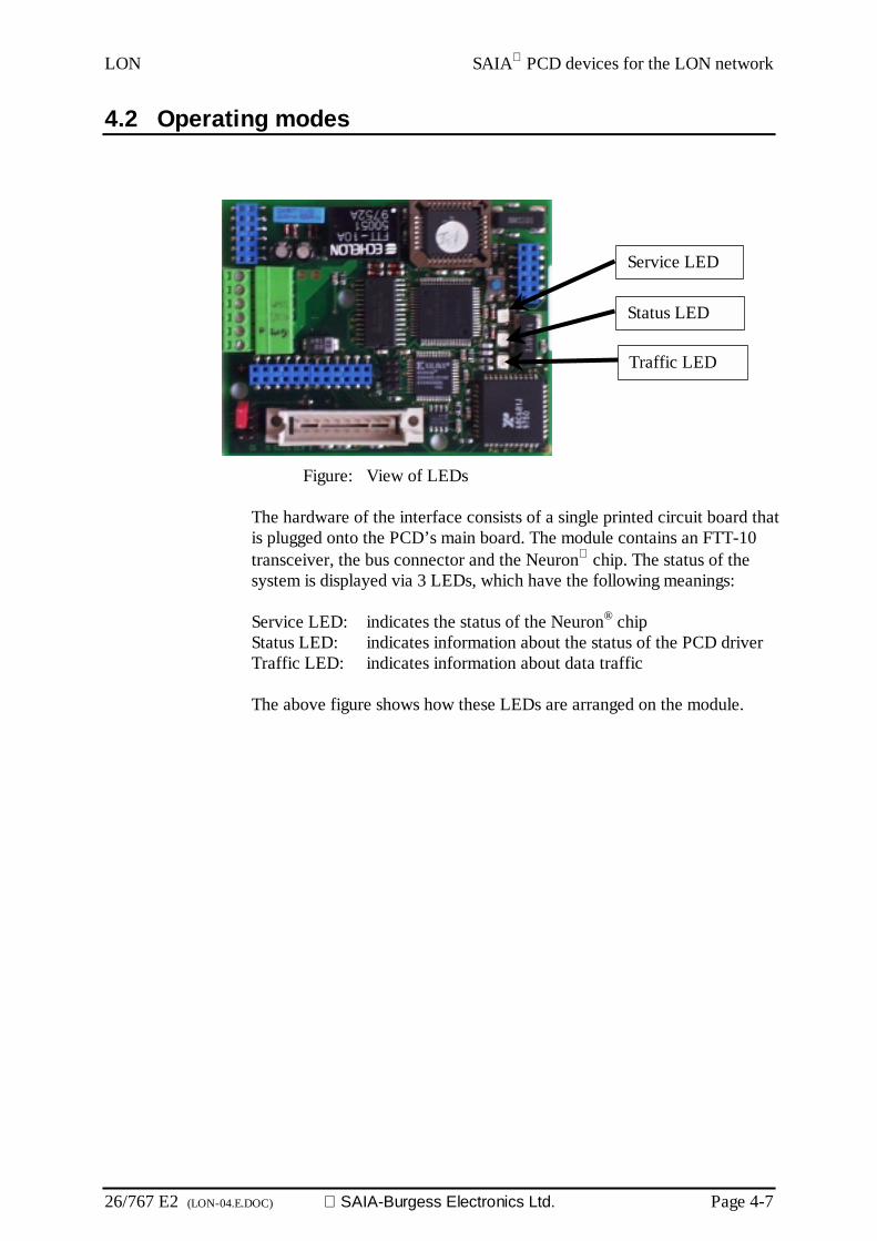
LON SAIA PCD devices for the LON network
26/767 E2 (LON-04.E.DOC) SAIA-Burgess Electronics Ltd. Page 4-7
4.2 Operating modes
Figure: View of LEDs
The hardware of the interface consists of a single printed circuit board thatis plugged onto the PCD’s main board. The module contains an FTT-10transceiver, the bus connector and the Neuron chip. The status of thesystem is displayed via 3 LEDs, which have the following meanings:
Service LED: indicates the status of the Neuron® chipStatus LED: indicates information about the status of the PCD driverTraffic LED: indicates information about data traffic
The above figure shows how these LEDs are arranged on the module.
Service LED
Status LED
Traffic LED

SAIA PCD devices for the LON network LON
Page 4-8 SAIA-Burgess Electronics Ltd (LON-04.E.DOC) 26/767 E2
Behaviour of LEDs
The service LED is the Neuron® chip service LED. This LED is illumi-nated when the module is in reset status. The following diagram showsbehaviour for all possible states of the service LED:
A) Normal behaviour:In this status the Neuron® chip is configured and working in syn-chronous mode with the PCD’s microprocessor. During start-upthe LED comes on for a few milliseconds. A second brief flashcan be observed when the module synchronizes with the driverduring the start-up period.
B) Hardware error:In this status the LED shines continuously red from start-up. Insuch cases the module will probably have to be exchanged.
C) Application:In this application status the firmware of the Neuron® chip isfaulty. The LED comes on for 1 second after start-up, then goesoff for 2 seconds, and then comes on permanently.
D) Not configured:In this status the installation tool has not yet configured the nodeor the configuration has been changed. This status is indicatedby LED blinking on a 2-second cycle. (1 second on, 1 secondoff).
E) Software error:If there is a software error (Interface Synchronization Error) theLED flashes briefly every 750 ms. To remove the cause of theerror it is necessary to execute a PCD coldstart.
A
DCB
E
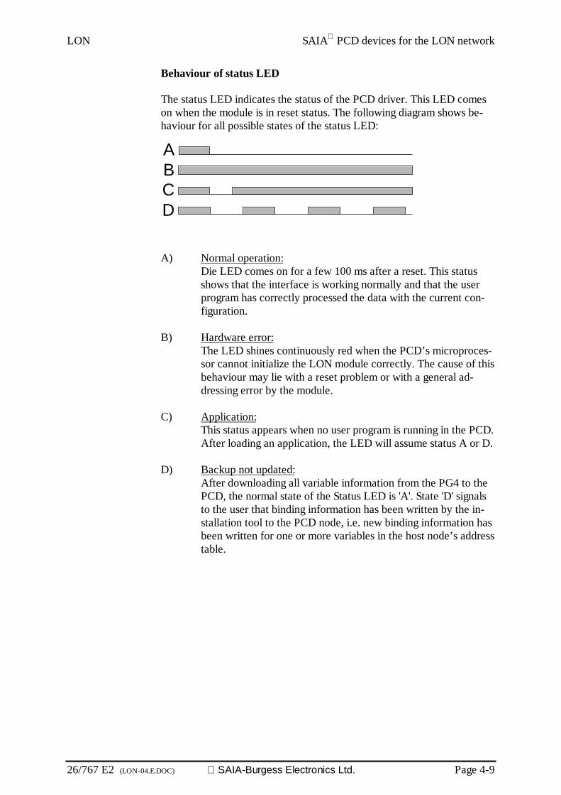
LON SAIA PCD devices for the LON network
26/767 E2 (LON-04.E.DOC) SAIA-Burgess Electronics Ltd. Page 4-9
Behaviour of status LED
The status LED indicates the status of the PCD driver. This LED comeson when the module is in reset status. The following diagram shows be-haviour for all possible states of the status LED:
A) Normal operation:Die LED comes on for a few 100 ms after a reset. This statusshows that the interface is working normally and that the userprogram has correctly processed the data with the current con-figuration.
B) Hardware error:The LED shines continuously red when the PCD’s microproces-sor cannot initialize the LON module correctly. The cause of thisbehaviour may lie with a reset problem or with a general ad-dressing error by the module.
C) Application:This status appears when no user program is running in the PCD.After loading an application, the LED will assume status A or D.
D) Backup not updated:After downloading all variable information from the PG4 to thePCD, the normal state of the Status LED is 'A'. State 'D' signalsto the user that binding information has been written by the in-stallation tool to the PCD node, i.e. new binding information hasbeen written for one or more variables in the host node’s addresstable.
A
DCB
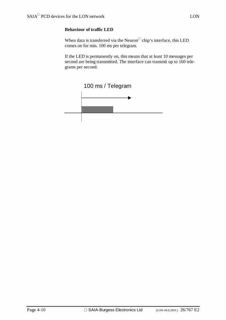
SAIA PCD devices for the LON network LON
Page 4-10 SAIA-Burgess Electronics Ltd (LON-04.E.DOC) 26/767 E2
Behaviour of traffic LED
When data is transferred via the Neuron chip’s interface, this LEDcomes on for min. 100 ms per telegram.
If the LED is permanently on, this means that at least 10 messages persecond are being transmitted. The interface can transmit up to 160 tele-grams per second.
100 ms / Telegram

LON Planning and installation
26/767 E2 (LON-05-E.DOC) SAIA-Burgess Electronics Ltd. Page 5-1
5. Planning and installation of aLON network
All information for this chapter should be taken from the homepageslisted below:
http://www.lontech.ch/
http://www.echelon.com/
http://www.lonmark.org/
Planning and installation LON
Page 5-2 SAIA-Burgess Electronics Ltd. (LON-05-E.DOC) 26/767 E2
Notes
LON LON configurator
26/767 E2 (LON-06-E.DOC) SAIA-Burgess Electronics Ltd. Page 6-1
6. LON configuratorThe definition and configuration (bus parameters, network stations andvariable definition) of a LON host node can be quite extensive, depend-ing on the size of the project. This task is made considerably easier forthe user by means of the PG4 LON configurator.

LON configurator LON
Page 6-2 SAIA-Burgess Electronics Ltd. (LON-06-E.DOC) 26/767 E2
6.1 General
The LON configurator comprises software (PG4 or higher) that runs un-der MS-Windows 95 and higher. The operating system must have 32-bitwide data access. No special hardware is required. Windows technologyapplies throughout. This results in a good overview and gives very user-friendly parameter entry.
LON LON configurator
26/767 E2 (LON-06-E.DOC) SAIA-Burgess Electronics Ltd. Page 6-3
6.2 Procedure for LON configuration
The procedure can be divided into the following steps:
1. Starting PG4
2. Definition of a new project
3. Definition and calling of a LON project in the project manager
4. Selection of LON host node in the network configurator
5. Definition of variables
6. Definition of station parameters
7. Saving the configuration
8. Generating the documentation
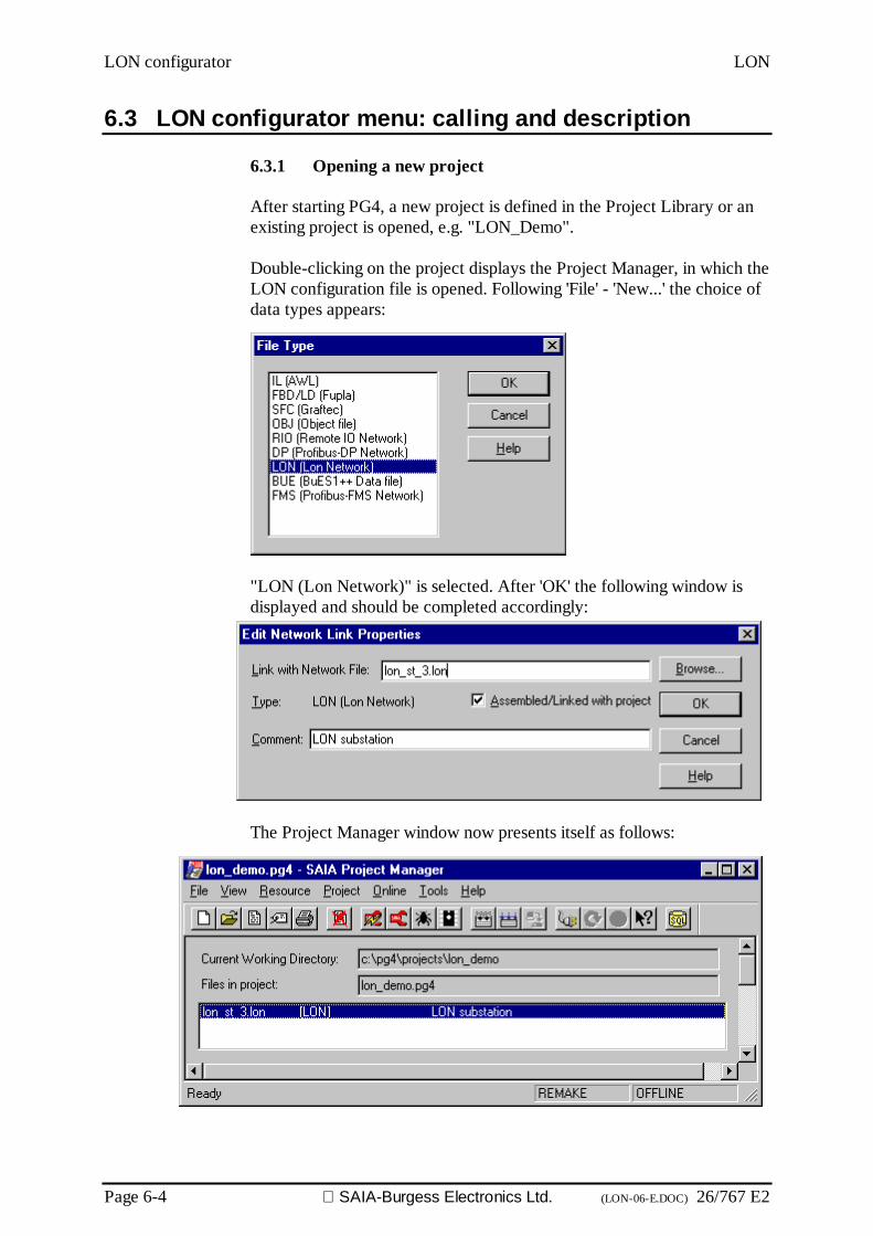
LON configurator LON
Page 6-4 SAIA-Burgess Electronics Ltd. (LON-06-E.DOC) 26/767 E2
6.3 LON configurator menu: calling and description
6.3.1 Opening a new project
After starting PG4, a new project is defined in the Project Library or anexisting project is opened, e.g. "LON_Demo".
Double-clicking on the project displays the Project Manager, in which theLON configuration file is opened. Following 'File' - 'New...' the choice ofdata types appears:
"LON (Lon Network)" is selected. After 'OK' the following window isdisplayed and should be completed accordingly:
The Project Manager window now presents itself as follows:
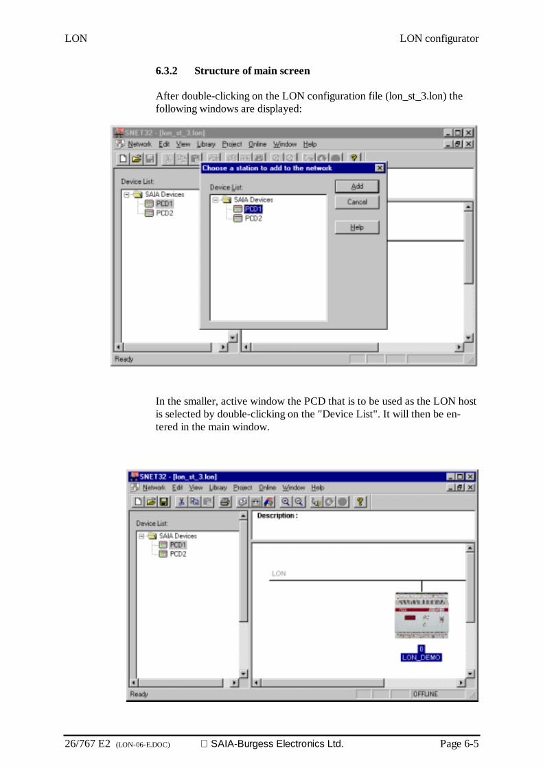
LON LON configurator
26/767 E2 (LON-06-E.DOC) SAIA-Burgess Electronics Ltd. Page 6-5
6.3.2 Structure of main screen
After double-clicking on the LON configuration file (lon_st_3.lon) thefollowing windows are displayed:
In the smaller, active window the PCD that is to be used as the LON hostis selected by double-clicking on the "Device List". It will then be en-tered in the main window.

LON configurator LON
Page 6-6 SAIA-Burgess Electronics Ltd. (LON-06-E.DOC) 26/767 E2
After double-clicking on the "Description:" field the following windowappears and can be completed accordingly. Clicking on 'OK' enters the
edited description text in the "Description" field.
The main screen presentation is now similar to the following:
Meaning of mouse buttons on individual windows:
'Device List' window:Left mouse button: Double-clicking on the device inserts it in the
network.Right mouse button: To open menu Insert Station / Add / Remove De-
vice
'Description' window:Left mouse button: Double-clicking on the description opens the net-
work description entry window.
'Network' window:Left mouse button: Double-clicking on a device opens parameter in-
put for the device.Right mouse button: To open menu Parameter / Edit Project / Cut /
Copy / Duplicate / Delete / Print.

LON LON configurator
26/767 E2 (LON-06-E.DOC) SAIA-Burgess Electronics Ltd. Page 6-7
Caution: Use of the functions listed above is limited in a LONnode configuration because a maximum of one LONstation can be configured in any project.
The following error message appears if the user tries toconfigure more than one station.
Station Parameters...':
Station: Name: The station name is entered here.Node: This value remains by default at "0", since
the node address is allocated via the in-stallation tool.
Node ID: Allocation of a name with max. 8 charac-ters for node identification in the installa-tion tool.
Project File: Path assignment for storing the projectfile.
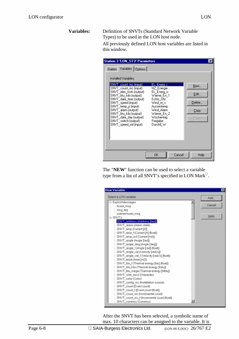
LON configurator LON
Page 6-8 SAIA-Burgess Electronics Ltd. (LON-06-E.DOC) 26/767 E2
Variables: Definition of SNVTs (Standard Network VariableTypes) to be used in the LON host node.All previously defined LON host variables are listed inthis window.
The "NEW" function can be used to select a variabletype from a list of all SNVT’s specified in LON Mark .
After the SNVT has been selected, a symbolic name ofmax. 10 characters can be assigned to the variable. It is

LON LON configurator
26/767 E2 (LON-06-E.DOC) SAIA-Burgess Electronics Ltd. Page 6-9
also necessary to define whether this is an input or an out-put variable.
The "Count" option, in connection with the FBoxes,enables several SNVTs of the same type to be config-ured in a single operation.
Options: This submenu is intended to allow the user to extendthe current total of 15 address tables. Since at presentthe limit for LON-Talk is 15 address tables, this pa-rameter remains unchanged at zero.(This expansion has been requested from ECHELON.)

LON configurator LON
Page 6-10 SAIA-Burgess Electronics Ltd. (LON-06-E.DOC) 26/767 E2
6.4 Menus of the LON configurator
The following submenus can be selected from the list of tools at the top:
• Network• Edit• View• Library• Project• Online• Windows• Help

LON LON configurator
26/767 E2 (LON-06-E.DOC) SAIA-Burgess Electronics Ltd. Page 6-11
6.4.1 Structure of the 'Network' submenu
'New': In this menu a new project is opened. At the same timethere is an opportunity to choose between aPROFIBUS-DP, SRIO or LON network.Corresponds to the following icon on the toolbar:
'Open': To open an existing project.Corresponds to the following icon on the toolbar:
'Close: To close an active project.
'Save': To save an active project under its current name.Corresponds to the following icon on the toolbar:
'Save as...': To save an active project under a new name.
'Description...': To describe the project. This description can be seen onthe main screen in the upper right-hand window.
'Print...': To print out the configuration parameters of a project.Parameters can also be printed in an ASCII file.

LON configurator LON
Page 6-12 SAIA-Burgess Electronics Ltd. (LON-06-E.DOC) 26/767 E2
'Print Preview': To produce a preview of the printout on the screen.This indicates all devices used, their settings and therelevant media.
'Print Setup...': To adjust the setup of printer type and paper format.
1 .. 4: To display the 4 projects most recently worked on.
Exit: To close SNET.

LON LON configurator
26/767 E2 (LON-06-E.DOC) SAIA-Burgess Electronics Ltd. Page 6-13
6.4.2 Structure of the 'Edit' submenu
'Cut': To cut out and save a selected LON node to the note-pad. This involves copying the entire configuration ofdevices, i.e. installed variables accompany the node.Corresponds to the following icon on the toolbar:
'Copy': To copy a selected LON node to the notepad. This in-volves copying the entire configuration of devices, i.e.installed variables accompany the node.Corresponds to the following icon on the toolbar:
'Paste': To insert a LON node, located on the notepad, into theactive project. This involves carrying over the entireconfiguration of devices, i.e. installed variables accom-pany the node.Corresponds to the following icon on the toolbar :
'Duplicate': To create a copy of a selected LON node. Correspondsto the COPY and PASTE sequence of instructions. Thisinvolves carrying over the entire configuration of de-vices for the equipment selected, i.e. installed variablesaccompany the node.
'Delete': To delete a selected LON node.
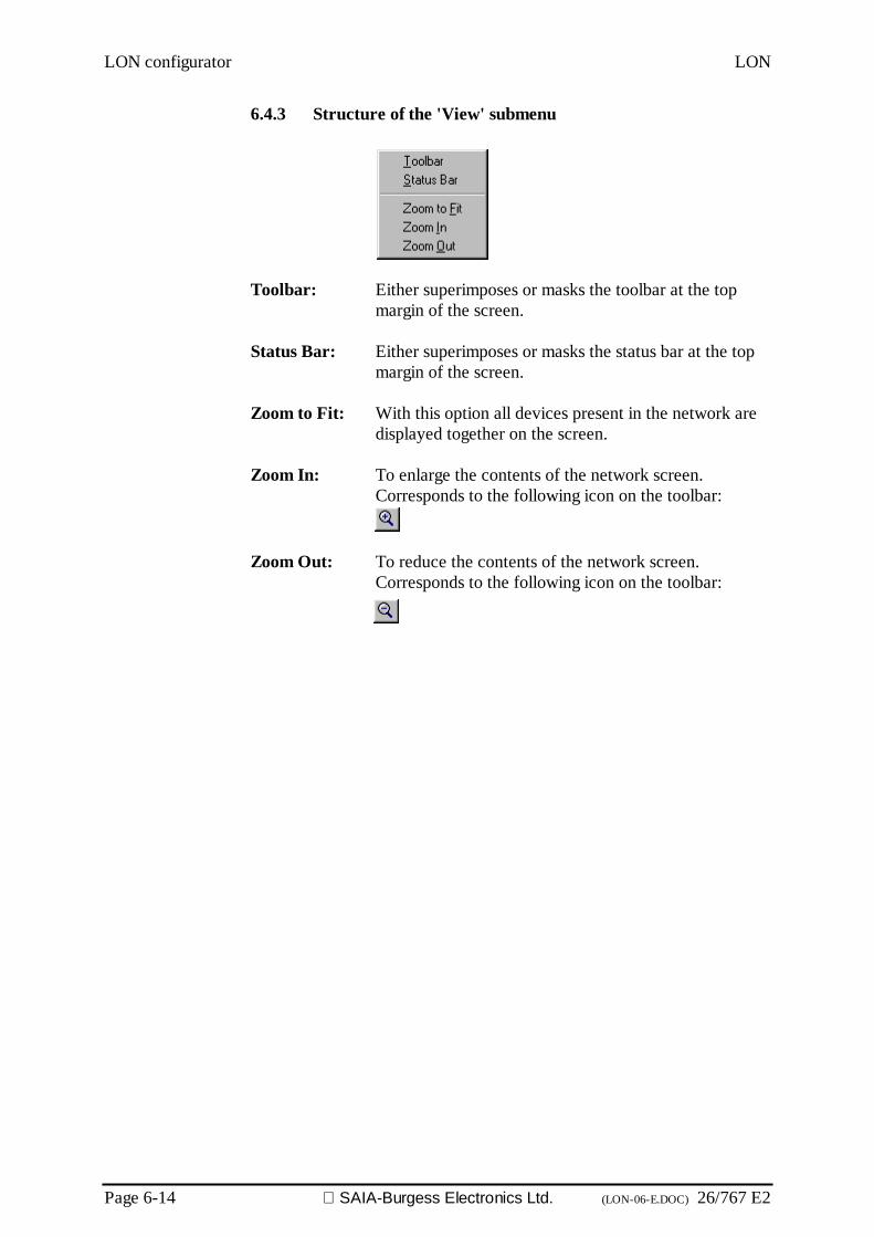
LON configurator LON
Page 6-14 SAIA-Burgess Electronics Ltd. (LON-06-E.DOC) 26/767 E2
6.4.3 Structure of the 'View' submenu
Toolbar: Either superimposes or masks the toolbar at the topmargin of the screen.
Status Bar: Either superimposes or masks the status bar at the topmargin of the screen.
Zoom to Fit: With this option all devices present in the network aredisplayed together on the screen.
Zoom In: To enlarge the contents of the network screen.Corresponds to the following icon on the toolbar:
Zoom Out: To reduce the contents of the network screen.Corresponds to the following icon on the toolbar:

LON LON configurator
26/767 E2 (LON-06-E.DOC) SAIA-Burgess Electronics Ltd. Page 6-15
6.4.4 Structure of the 'Library' submenu
Add Device: To insert new LON nodes.These nodes must have a file with the extension '.ldd'.
After selection of the '.ldd' file, the device can be as-signed to a device group.
This may involve saving the device either in an existinggroup or a new one
To define a new group, the new group name is simplyentered in the entry field.
This new group will then automatically be inserted inthe device list:
Remove Device: To delete a LON device node from the device list.
Rename Group: To rename a device group (not active here).
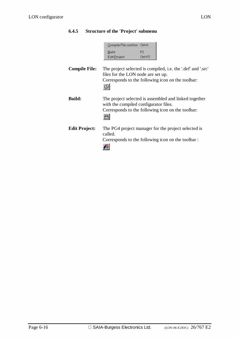
LON configurator LON
Page 6-16 SAIA-Burgess Electronics Ltd. (LON-06-E.DOC) 26/767 E2
6.4.5 Structure of the 'Project' submenu
Compile File: The project selected is compiled, i.e. the '.def' and '.src'files for the LON node are set up.Corresponds to the following icon on the toolbar:
Build: The project selected is assembled and linked togetherwith the compiled configurator files.Corresponds to the following icon on the toolbar:
Edit Project: The PG4 project manager for the project selected iscalled.Corresponds to the following icon on the toolbar :

LON LON configurator
26/767 E2 (LON-06-E.DOC) SAIA-Burgess Electronics Ltd. Page 6-17
6.4.6 Structure of the 'Online' submenu
Go Online: Switches the window online
UploadDBX...: This function serves to save the binding information.All information that has been stored by the binding toolin the host node can be saved by this route and put inproject-specific store on the PC.Important: Before downloading new program informa-tion into the PCD, binding information must be savedvia 'UploadDBX...', as otherwise all bindings in the hostnode will be lost!
Important: After the variables (SNVTs) of a LON proj-ect have been bound, it is important to execute a cold-start, so that the binding information is transferred fromLON module memory to PCD memory.
Run: If online, switches the CPU into Run
Stop: If online, switches the CPU into Stop
PCD Status: Indicates the status of the CPU
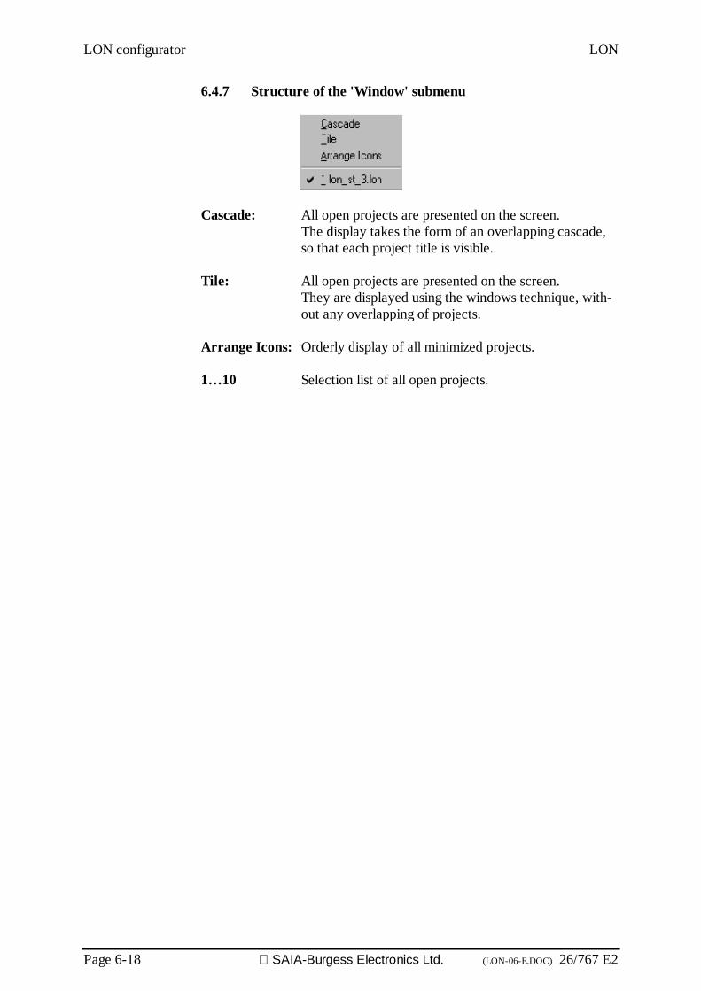
LON configurator LON
Page 6-18 SAIA-Burgess Electronics Ltd. (LON-06-E.DOC) 26/767 E2
6.4.7 Structure of the 'Window' submenu
Cascade: All open projects are presented on the screen.The display takes the form of an overlapping cascade,so that each project title is visible.
Tile: All open projects are presented on the screen.They are displayed using the windows technique, with-out any overlapping of projects.
Arrange Icons: Orderly display of all minimized projects.
1…10 Selection list of all open projects.
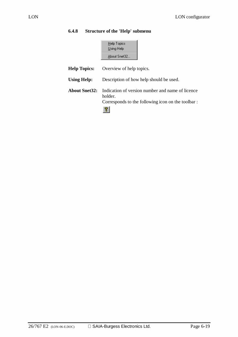
LON LON configurator
26/767 E2 (LON-06-E.DOC) SAIA-Burgess Electronics Ltd. Page 6-19
6.4.8 Structure of the 'Help' submenu
Help Topics: Overview of help topics.
Using Help: Description of how help should be used.
About Snet32: Indication of version number and name of licenceholder.Corresponds to the following icon on the toolbar :

LON configurator LON
Page 6-20 SAIA-Burgess Electronics Ltd. (LON-06-E.DOC) 26/767 E2
Notes

LON Programming
26/767 E2 (LON-07-E.DOC) SAIA-Burgess Electronics Ltd. Page 7-1
7. Programming in the user program
Use of the LON variables (SNVT) in thePCD user program (LON library)
Overview
LON LIBRARY OVERVIEW.............................................................................. 3
SUB TOPICS.................................................................................................... 4LON Fboxes and the LON Configurator...............................................................................4SNVT List.............................................................................................................................5The auto send mechanism ...................................................................................................7
SND AND RCV FBOXES.................................................................................. 9Binary ...................................................................................................................................9
RCV Binary......................................................................................................................... 9RCV Binary Rcv ................................................................................................................ 10RCV Binary+Value Rcv ...................................................................................................... 11RCV Binary Code .............................................................................................................. 12SEND Binary..................................................................................................................... 13SEND Binary Snd .............................................................................................................. 14SEND Binary Auto ............................................................................................................. 15SEND Binary+Value Auto ................................................................................................... 16SEND Binary Code Auto .................................................................................................... 17
Integer ................................................................................................................................18RCV Integer...................................................................................................................... 18RCV Integer Rcv ............................................................................................................... 19SEND Integer.................................................................................................................... 20SEND Integer Snd ............................................................................................................. 21SEND Integer Auto ............................................................................................................ 22
Temperature Setpoints.......................................................................................................23RCV Temp Setpoints Rcv................................................................................................... 23SEND Temp Setpoints Snd ................................................................................................ 24
Floating point......................................................................................................................25RCV Floating point............................................................................................................. 25RCV Floating point Rcv...................................................................................................... 26SEND Floating point........................................................................................................... 27SEND Floating point Snd.................................................................................................... 28SEND Floating point Auto................................................................................................... 29
Date and Time....................................................................................................................30RCV Date and Time........................................................................................................... 30SEND Date and Time......................................................................................................... 31
State...................................................................................................................................32RCV State ........................................................................................................................ 32SEND State ...................................................................................................................... 33
Alarm..................................................................................................................................34RCV Alarm........................................................................................................................ 34SEND Alarm...................................................................................................................... 35
Object.................................................................................................................................36RCV Object Status ............................................................................................................ 36SEND Object Request ....................................................................................................... 37
Programming LON
Page 7-2 SAIA-Burgess Electronics Ltd. (LON-07-E.DOC) 26/767 E2
Magnetic Cards..................................................................................................................38RCV Magnetic Cards......................................................................................................... 38SEND Magnetic Cards....................................................................................................... 39
Settings ..............................................................................................................................40RCV Settings .................................................................................................................... 40SEND Settings .................................................................................................................. 41
OTHER FBOXES............................................................................................ 42LON Diagnostics................................................................................................................42SNVT Diagnostic ...............................................................................................................44

LON Programming
26/767 E2 (LON-07-E.DOC) SAIA-Burgess Electronics Ltd. Page 7-3
LON Library Overview
Use the 'Help Topics' button as to find the description of all the Fbox in this library.
If you are beginner, read this important topic first:
LON Fboxes and the LON Configurator.
As to find the Fbox supporting a particular SNVT go to the
SNVT List.
For more details about SNVT definitions, formats and structures, please consult the SNVT Master List.
The german and french help files can also be consulted if they are installed.

Programming LON
Page 7-4 SAIA-Burgess Electronics Ltd. (LON-07-E.DOC) 26/767 E2
Sub topics
LON Fboxes and the LON Configurator
As to connect PCD variables to the LON Network, you need :1. to configure the LON variable using the LON Configurator2. to place a suitable Fbox in Fupla and connect the PCD variable
The LON Configurator can be called from the Project Manager. Define your LON Variables (SNVT) and chose thesuitable options. The name you gave to the SNVT will be used to make reference to it in the Fupla.
See the Help of the LON Configurator for more details.
In Fupla, for each SNVT, choose the corresponding Fbox. The value format and the direction must fit to the declaration made inthe LON Configurator.
• Binary SNVTs need a Binary Fbox• Numeric SNVTs (1 to 4 bytes) need Integer Fboxes• Float SNVTs need Float Fboxes.• PCD Inputs need SND Fboxes• PCD Outputs need RCV Fboxes
Click on the ‘ref:????’ label on Fbox as to type the reference. In the reference field, type the name you have de-clared in the LON Configurator. In this way, the Fbox will have access the corresponding SNVT.
If you declare an array of SNVT you have to give one single name for all SNVT in the array. You must use aStretchable Fbox for the SNVT array. Internally, the SNVT name will be extended with a index. (Name00, Name01, Name 02…).
If the Fbox does not match the referenced SNVT, assembling errors will occur.
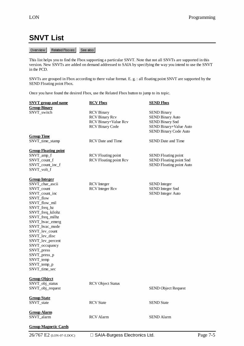
LON Programming
26/767 E2 (LON-07-E.DOC) SAIA-Burgess Electronics Ltd. Page 7-5
SNVT List
This list helps you to find the Fbox supporting a particular SNVT. Note that not all SNVTs are supported in thisversion. New SNVTs are added on demand addressed to SAIA by specifying the way you intend to use the SNVTin the PCD.
SNVTs are grouped in Fbox according to there value format. E. g. : all floating point SNVT are supported by theSEND Floating point Fbox.
Once you have found the desired Fbox, use the Related Fbox button to jump to its topic.
SNVT group and name RCV Fbox SEND FboxGroup BinarySNVT_switch RCV Binary
RCV Binary RcvRCV Binary+Value RcvRCV Binary Code
SEND BinarySEND Binary AutoSEND Binary SndSEND Binary+Value AutoSEND Binary Code Auto
Group TimeSNVT_time_stamp RCV Date and Time SEND Date and Time
Group Floating pointSNVT_amp_fSNVT_count_fSNVT_count_inc_fSNVT_volt_f
RCV Floating pointRCV Floating point Rcv
SEND Floating pointSEND Floating point SndSEND Floating point Auto
Group IntegerSNVT_char_asciiSNVT_countSNVT_count_incSNVT_flowSNVT_flow_milSNVT_freq_hzSNVT_freq_kilohzSNVT_freq_milhzSNVT_hvac_emergSNVT_hvac_modeSNVT_lev_countSNVT_lev_discSNVT_lev_percentSNVT_occupancySNVT_pressSNVT_press_pSNVT_tempSNVT_temp_pSNVT_time_sec
RCV IntegerRCV Integer Rcv
SEND IntegerSEND Integer SndSEND Integer Auto
Group ObjectSNVT_obj_statusSNVT_obj_request
RCV Object StatusSEND Object Request
Group StateSNVT_state RCV State SEND State
Group AlarmSNVT_alarm RCV Alarm SEND Alarm
Group Magnetic Cards

Programming LON
Page 7-6 SAIA-Burgess Electronics Ltd. (LON-07-E.DOC) 26/767 E2
SNVT_magcrd RCV Magnetic Cards SEND Magnetic Cards
Group SettingsSNVT_Setting RCV Settings SEND Settings
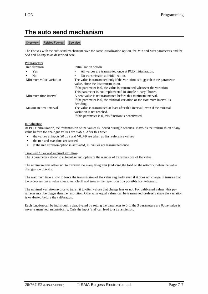
LON Programming
26/767 E2 (LON-07-E.DOC) SAIA-Burgess Electronics Ltd. Page 7-7
The auto send mechanism
The Fboxes with the auto send mechanism have the same initialization option, the Min and Max parameters and theSnd and En inputs as described here.
PararametersInitialization• Yes• No
Initialization option• All values are transmitted once at PCD initialization.• No transmission at initialization.
Minimum value variation The value is transmitted only if the variation is bigger than the parametervalue, since the last transmission.If the parameter is 0, the value is transmitted whatever the variation.This parameter is not implemented in simple binary Fboxes.
Minimum time interval A new value is not transmitted before this minimum interval.If the parameter is 0, the minimal variation or the maximum interval isdeciding.
Maximum time interval The value is transmitted at least after this interval, even if the minimalvariation is not reached.If this parameter is 0, this function is deactivated.
InitializationAt PCD initialization, the transmission of the values is locked during 2 seconds. It avoids the transmission of anyvalue before the analogue values are stable. After this time:
• the values at inputs S0 ..S9 and V0..V9 are taken as first reference values• the min and max time are started• if the initialization option is activated, all values are transmitted once
Time min / max and minimal variationThe 3 parameters allow to automatize and optimize the number of transmissions of the value.
The minimum time allow not to transmit too many telegrams (reducing the load on the network) when the valuechanges too quickly.
The maximum time allow to force the transmission of the value regularly even if it does not change. It insures thatthe receivers has a value after a switch off and insures the repetition of a possibly lost telegram.
The minimal variation avoids to transmit to often values that change less or not. For calibrated values, this pa-rameter must be bigger than the resolution. Otherwise equal values can be transmitted uselessly since the variationis evaluated before the calibration.
Each function can be individually deactivated by setting the parameter to 0. If the 3 parameters are 0, the value isnever transmitted automatically. Only the input 'Snd' can lead to a transmission.
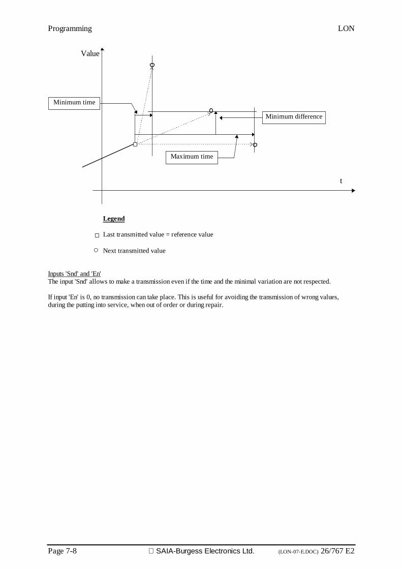
Programming LON
Page 7-8 SAIA-Burgess Electronics Ltd. (LON-07-E.DOC) 26/767 E2
Value
t
Minimum time
Maximum time
Minimum difference
Legend
Last transmitted value = reference value
Next transmitted value
Inputs 'Snd' and 'En'The input 'Snd' allows to make a transmission even if the time and the minimal variation are not respected.
If input 'En' is 0, no transmission can take place. This is useful for avoiding the transmission of wrong values,during the putting into service, when out of order or during repair.
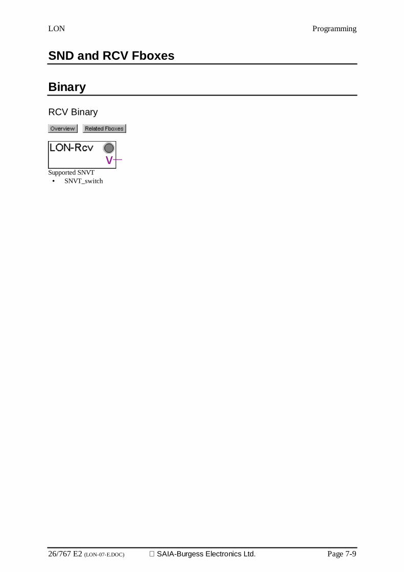
LON Programming
26/767 E2 (LON-07-E.DOC) SAIA-Burgess Electronics Ltd. Page 7-9
SND and RCV Fboxes
Binary
RCV Binary
Supported SNVT• SNVT_switch
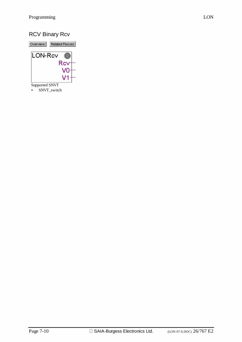
Programming LON
Page 7-10 SAIA-Burgess Electronics Ltd. (LON-07-E.DOC) 26/767 E2
RCV Binary Rcv
Supported SNVT• SNVT_switch

LON Programming
26/767 E2 (LON-07-E.DOC) SAIA-Burgess Electronics Ltd. Page 7-11
RCV Binary+Value Rcv
Supported SNVT• SNVT_switch
Outputs / LEDRcv Received Set to one for one cycle when new data have been received.S0..S9 State Binary state.V0..V9 Value Numeric value. The output value is scaled according to the ad-
justed value range.LED LED The LED is red in case of reception error.
ParametersRange of output signals Range of the output signal corresponding to 100 %.
The received LON value has a resolution of half percent.Range 1000 means a resolution of 5 units.The LON value is in range 0 to 200 to represent 0 to 100%. Arange of 200 will output the LON value as received.

Programming LON
Page 7-12 SAIA-Burgess Electronics Ltd. (LON-07-E.DOC) 26/767 E2
RCV Binary Code
Supported SNVT• SNVT_switch
Outputs / LEDRcv Received Set to one for one cycle when new data have been received.S0..S9 State Binary state.LED LED The LED is red in case of reception error.
ParametersCode for state OFF Code to receive for the output state OFF, hex coded.Code for state ON Code to receive for the output state ON, hex coded.
DescriptionThis particular Fbox allows to specify the code received for the states ON and OFF. It is possible to adapt theSNVT_switch for a device deviating from the standard definition. The SNVT_switch is build of a two bytes code.The higher byte is a value to be evaluated in percent (range 0 to 200), the lower byte is a binary state. If only abinary state is needed, the standard code for the ON state is C801 hex (means 100% ON) while the code for theOFF state is 0000 hex. However some devices use the code 0001 hex for the ON state.
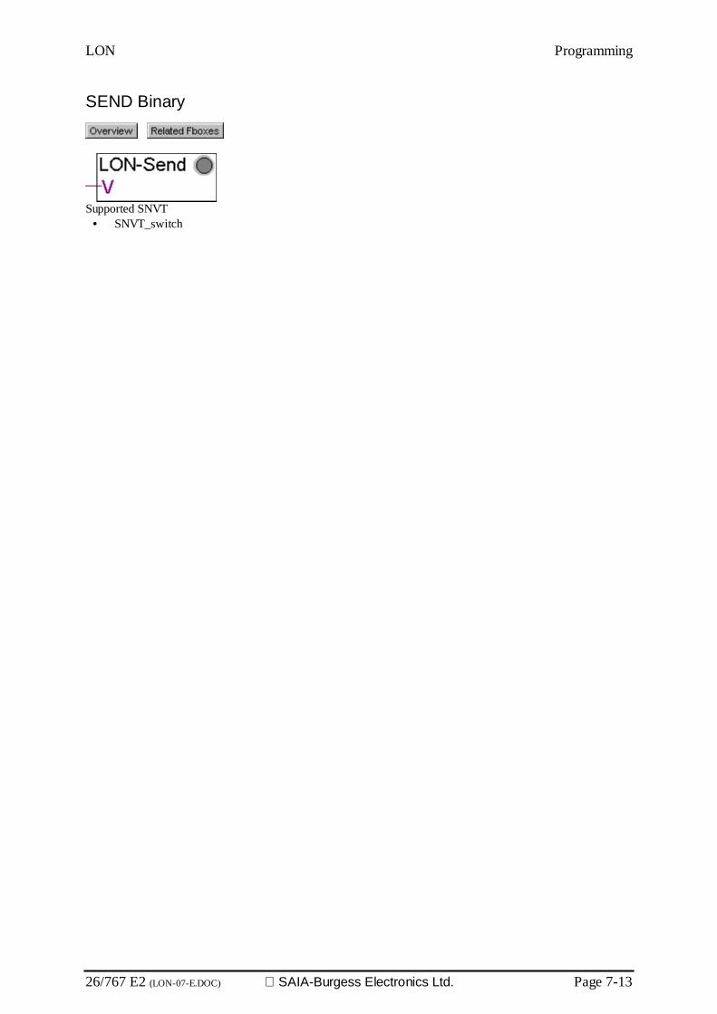
LON Programming
26/767 E2 (LON-07-E.DOC) SAIA-Burgess Electronics Ltd. Page 7-13
SEND Binary
Supported SNVT• SNVT_switch
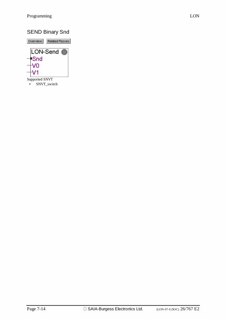
Programming LON
Page 7-14 SAIA-Burgess Electronics Ltd. (LON-07-E.DOC) 26/767 E2
SEND Binary Snd
Supported SNVT• SNVT_switch

LON Programming
26/767 E2 (LON-07-E.DOC) SAIA-Burgess Electronics Ltd. Page 7-15
SEND Binary Auto
Supported SNVT• SNVT_switch

Programming LON
Page 7-16 SAIA-Burgess Electronics Ltd. (LON-07-E.DOC) 26/767 E2
SEND Binary+Value Auto
Supported SNVT• SNVT_switch
Inputs / LEDSnd Send An impulse on Snd activates the transmission.En Enable Enables the transmission.S0..S9 State Binary state.V0..V9 Value Numeric value. The input value is scaled according to the adjusted
value range.LED LED The LED is red in case of reception error.
ParametersRange of input signals Range of the input signals corresponding to 100 %.
The received LON value has a resolution of half percent.Range 1000 means a resolution of 5 units.The LON value is in range 0 to 200 to represent 0 to 100%. Arange of 200 will send the input value to the LON network withoutconversion.
Other parameters See the topic: The auto send mechanism

LON Programming
26/767 E2 (LON-07-E.DOC) SAIA-Burgess Electronics Ltd. Page 7-17
SEND Binary Code Auto
Supported SNVT• SNVT_switch
Inputs / LEDSnd Send An impulse on Snd activates the transmission.En Enable Enables the transmission.S0..S9 State Binary state.LED LED The LED is red in case of reception error.
ParametersCode for state OFF Code to send for the input state OFF, hex coded.Code for state ON Code to send for the input state ON, hex coded.Other parameters See the topic: The auto send mechanism
DescriptionThis particular Fbox allows to specify the code to send for the states ON and OFF. It is possible to adapt theSNVT_switch for a device deviating from the standard definition. The SNVT_switch is build of a two bytes code.The higher byte is a value to be evaluated in percent (range 0 to 200), the lower byte is a binary state. If only abinary state is needed, the standard code for the ON state is C801 hex (means 100% ON) while the code for theOFF state is 0000 hex. However, some devices use the code 0001 hex for the ON state.

Programming LON
Page 7-18 SAIA-Burgess Electronics Ltd. (LON-07-E.DOC) 26/767 E2
Integer
RCV Integer
Supported SNVT• SNVT_amp• SNVT_amp_mil• SNVT_angle• SNVT_angle_vel• SNVT_btu_kilo• SNVT_btu_mega• SNVT_char_ascii• SNVT_config_src• SNVT_count• SNVT_count_inc• SNVT_data_day• SNVT_elec_kwh• SNVT_elec_whr• SNVT_flow• SNVT_flow_mil• SNVT_freq_h• SNVT_freq_kilohz• SNVT_freq_milhz• SNVT_grammage• SNVT_hvac_emerg• SNVT_hvac_mode• SNVT_length• SNVT_length_kilo• SNVT_length_mic• SNVT_length_mil• SNVT_lev_count *• SNVT_lev_disc• SNVT_lev_percent *• SNVT_lux
• SNVT_mass• SNVT_mass_kilo• SNVT_mass_mega• SNVT_mass_mil• SNVT_occupancy• SNVT_override• SNVT_power• SNVT_power_kilo• SNVT_ppm• SNVT_press• SNVT_press_p• SNVT_res• SNVT_res_kilo• SNVT_rpm• SNVT_sound_db• SNVT_speed• SNVT_speed_mil• SNVT_telcom• SNVT_temp• SNVT_temp_p• SNVT_time_sec• SNVT_vol• SNVT_vol_kilo• SNVT_vol_mil• SNVT_volt• SNVT_volt_dbmv• SNVT_volt_kilo• SNVT_volt_mil
* These SNVT have not a decimal resolution like 1, 0.1, 0.01 or 0.001. Therefore a conversion of the transmittedvalue outside the Fbox may be needed.SNVT ResolutionSNVT_lev_cont 0.5SNVT_lev_percent 0.005

LON Programming
26/767 E2 (LON-07-E.DOC) SAIA-Burgess Electronics Ltd. Page 7-19
RCV Integer Rcv
Supported SNVT• SNVT_amp• SNVT_amp_mil• SNVT_angle• SNVT_angle_vel• SNVT_btu_kilo• SNVT_btu_mega• SNVT_char_ascii• SNVT_config_src• SNVT_count• SNVT_count_inc• SNVT_data_day• SNVT_elec_kwh• SNVT_elec_whr• SNVT_flow• SNVT_flow_mil• SNVT_freq_h• SNVT_freq_kilohz• SNVT_freq_milhz• SNVT_grammage• SNVT_hvac_emerg• SNVT_hvac_mode• SNVT_length• SNVT_length_kilo• SNVT_length_mic• SNVT_length_mil• SNVT_lev_count *• SNVT_lev_disc• SNVT_lev_percent *• SNVT_lux
• SNVT_mass• SNVT_mass_kilo• SNVT_mass_mega• SNVT_mass_mil• SNVT_occupancy• SNVT_override• SNVT_power• SNVT_power_kilo• SNVT_ppm• SNVT_press• SNVT_press_p• SNVT_res• SNVT_res_kilo• SNVT_rpm• SNVT_sound_db• SNVT_speed• SNVT_speed_mil• SNVT_telcom• SNVT_temp• SNVT_temp_p• SNVT_time_sec• SNVT_vol• SNVT_vol_kilo• SNVT_vol_mil• SNVT_volt• SNVT_volt_dbmv• SNVT_volt_kilo• SNVT_volt_mil
* These SNVT have not a decimal resolution like 1, 0.1, 0.01 or 0.001. Therefore a conversion of the transmittedvalue outside the Fbox may be needed.SNVT ResolutionSNVT_lev_cont 0.5SNVT_lev_percent 0.005

Programming LON
Page 7-20 SAIA-Burgess Electronics Ltd. (LON-07-E.DOC) 26/767 E2
SEND Integer
Supported SNVT• SNVT_amp• SNVT_amp_mil• SNVT_angle• SNVT_angle_vel• SNVT_btu_kilo• SNVT_btu_mega• SNVT_char_ascii• SNVT_config_src• SNVT_count• SNVT_count_inc• SNVT_data_day• SNVT_elec_kwh• SNVT_elec_whr• SNVT_flow• SNVT_flow_mil• SNVT_freq_h• SNVT_freq_kilohz• SNVT_freq_milhz• SNVT_grammage• SNVT_hvac_emerg• SNVT_hvac_mode• SNVT_length• SNVT_length_kilo• SNVT_length_mic• SNVT_length_mil• SNVT_lev_count *• SNVT_lev_disc• SNVT_lev_percent *• SNVT_lux
• SNVT_mass• SNVT_mass_kilo• SNVT_mass_mega• SNVT_mass_mil• SNVT_occupancy• SNVT_override• SNVT_power• SNVT_power_kilo• SNVT_ppm• SNVT_press• SNVT_press_p• SNVT_res• SNVT_res_kilo• SNVT_rpm• SNVT_sound_db• SNVT_speed• SNVT_speed_mil• SNVT_telcom• SNVT_temp• SNVT_temp_p• SNVT_time_sec• SNVT_vol• SNVT_vol_kilo• SNVT_vol_mil• SNVT_volt• SNVT_volt_dbmv• SNVT_volt_kilo• SNVT_volt_mil
* These SNVT have not a decimal resolution like 1, 0.1, 0.01 or 0.001. Therefore a conversion of the transmittedvalue outside the Fbox may be needed.SNVT ResolutionSNVT_lev_cont 0.5SNVT_lev_percent 0.005
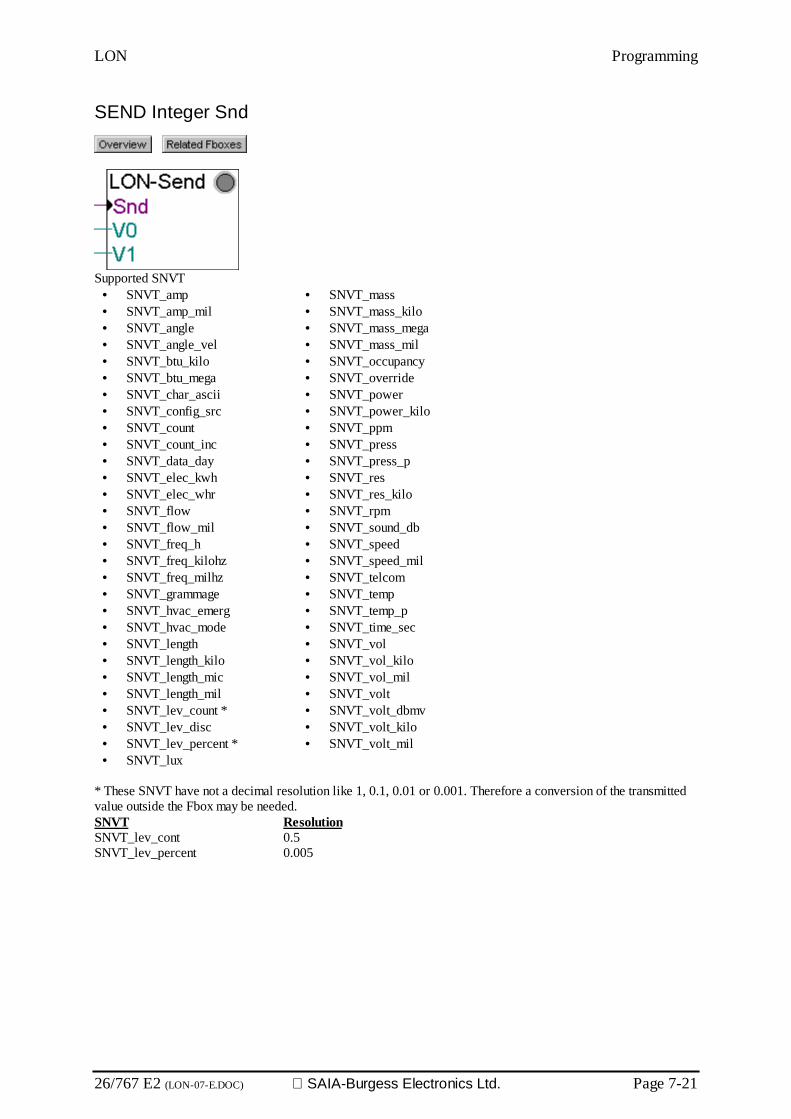
LON Programming
26/767 E2 (LON-07-E.DOC) SAIA-Burgess Electronics Ltd. Page 7-21
SEND Integer Snd
Supported SNVT• SNVT_amp• SNVT_amp_mil• SNVT_angle• SNVT_angle_vel• SNVT_btu_kilo• SNVT_btu_mega• SNVT_char_ascii• SNVT_config_src• SNVT_count• SNVT_count_inc• SNVT_data_day• SNVT_elec_kwh• SNVT_elec_whr• SNVT_flow• SNVT_flow_mil• SNVT_freq_h• SNVT_freq_kilohz• SNVT_freq_milhz• SNVT_grammage• SNVT_hvac_emerg• SNVT_hvac_mode• SNVT_length• SNVT_length_kilo• SNVT_length_mic• SNVT_length_mil• SNVT_lev_count *• SNVT_lev_disc• SNVT_lev_percent *• SNVT_lux
• SNVT_mass• SNVT_mass_kilo• SNVT_mass_mega• SNVT_mass_mil• SNVT_occupancy• SNVT_override• SNVT_power• SNVT_power_kilo• SNVT_ppm• SNVT_press• SNVT_press_p• SNVT_res• SNVT_res_kilo• SNVT_rpm• SNVT_sound_db• SNVT_speed• SNVT_speed_mil• SNVT_telcom• SNVT_temp• SNVT_temp_p• SNVT_time_sec• SNVT_vol• SNVT_vol_kilo• SNVT_vol_mil• SNVT_volt• SNVT_volt_dbmv• SNVT_volt_kilo• SNVT_volt_mil
* These SNVT have not a decimal resolution like 1, 0.1, 0.01 or 0.001. Therefore a conversion of the transmittedvalue outside the Fbox may be needed.SNVT ResolutionSNVT_lev_cont 0.5SNVT_lev_percent 0.005

Programming LON
Page 7-22 SAIA-Burgess Electronics Ltd. (LON-07-E.DOC) 26/767 E2
SEND Integer Auto
Supported SNVT• SNVT_amp• SNVT_amp_mil• SNVT_angle• SNVT_angle_vel• SNVT_btu_kilo• SNVT_btu_mega• SNVT_char_ascii• SNVT_config_src• SNVT_count• SNVT_count_inc• SNVT_data_day• SNVT_elec_kwh• SNVT_elec_whr• SNVT_flow• SNVT_flow_mil• SNVT_freq_h• SNVT_freq_kilohz• SNVT_freq_milhz• SNVT_grammage• SNVT_hvac_emerg• SNVT_hvac_mode• SNVT_length• SNVT_length_kilo• SNVT_length_mic• SNVT_length_mil• SNVT_lev_count *• SNVT_lev_disc• SNVT_lev_percent *• SNVT_lux
• SNVT_mass• SNVT_mass_kilo• SNVT_mass_mega• SNVT_mass_mil• SNVT_occupancy• SNVT_override• SNVT_power• SNVT_power_kilo• SNVT_ppm• SNVT_press• SNVT_press_p• SNVT_res• SNVT_res_kilo• SNVT_rpm• SNVT_sound_db• SNVT_speed• SNVT_speed_mil• SNVT_telcom• SNVT_temp• SNVT_temp_p• SNVT_time_sec• SNVT_vol• SNVT_vol_kilo• SNVT_vol_mil• SNVT_volt• SNVT_volt_dbmv• SNVT_volt_kilo• SNVT_volt_mil
* These SNVT have not a decimal resolution like 1, 0.1, 0.01 or 0.001. Therefore a conversion of the transmittedvalue outside the Fbox may be needed.SNVT ResolutionSNVT_lev_cont 0.5SNVT_lev_percent 0.005
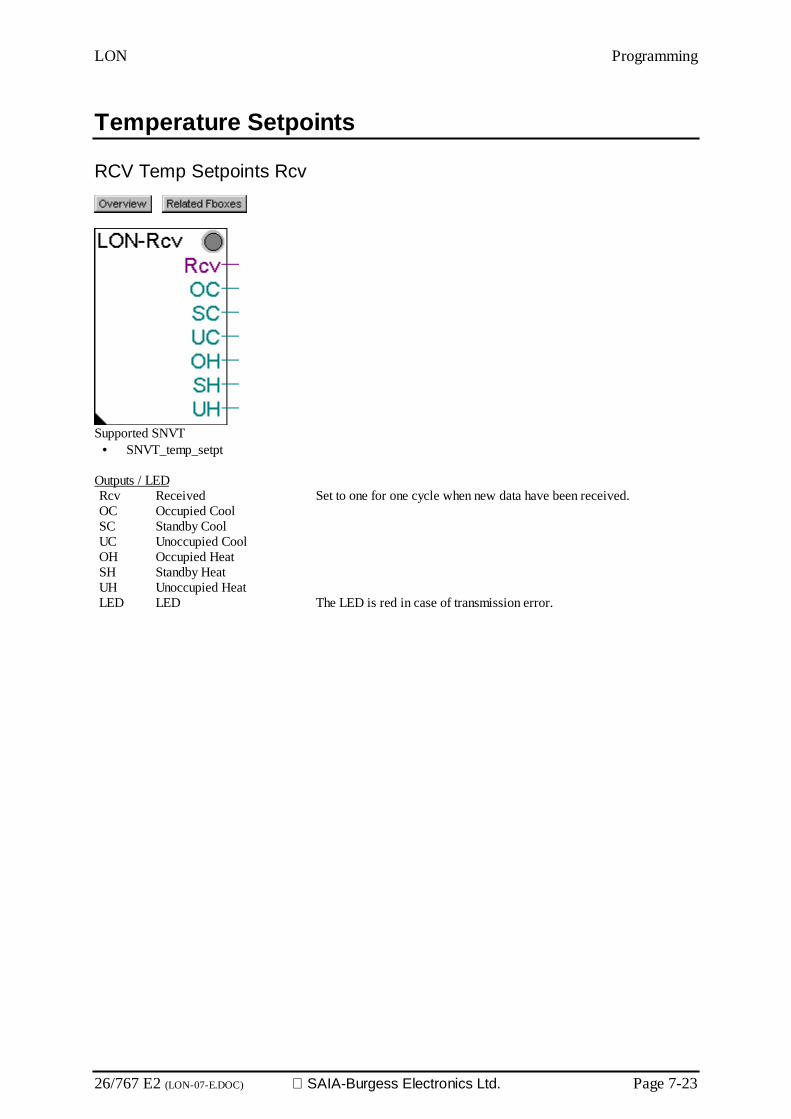
LON Programming
26/767 E2 (LON-07-E.DOC) SAIA-Burgess Electronics Ltd. Page 7-23
Temperature Setpoints
RCV Temp Setpoints Rcv
Supported SNVT• SNVT_temp_setpt
Outputs / LEDRcv Received Set to one for one cycle when new data have been received.OC Occupied CoolSC Standby CoolUC Unoccupied CoolOH Occupied HeatSH Standby HeatUH Unoccupied HeatLED LED The LED is red in case of transmission error.

Programming LON
Page 7-24 SAIA-Burgess Electronics Ltd. (LON-07-E.DOC) 26/767 E2
SEND Temp Setpoints Snd
Supported SNVT• SNVT_temp_setpt
Inputs / LEDSnd Send An impulse on Snd activates the transmission.OC Occupied CoolSC Standby CoolUC Unoccupied CoolOH Occupied HeatSH Standby HeatUH Unoccupied HeatLED LED The LED is red in case of transmission error.
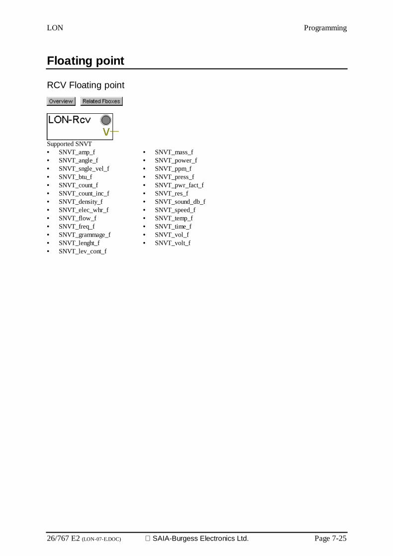
LON Programming
26/767 E2 (LON-07-E.DOC) SAIA-Burgess Electronics Ltd. Page 7-25
Floating point
RCV Floating point
Supported SNVT• SNVT_amp_f• SNVT_angle_f• SNVT_sngle_vel_f• SNVT_btu_f• SNVT_count_f• SNVT_count_inc_f• SNVT_density_f• SNVT_elec_whr_f• SNVT_flow_f• SNVT_freq_f• SNVT_grammage_f• SNVT_lenght_f• SNVT_lev_cont_f
• SNVT_mass_f• SNVT_power_f• SNVT_ppm_f• SNVT_press_f• SNVT_pwr_fact_f• SNVT_res_f• SNVT_sound_db_f• SNVT_speed_f• SNVT_temp_f• SNVT_time_f• SNVT_vol_f• SNVT_volt_f
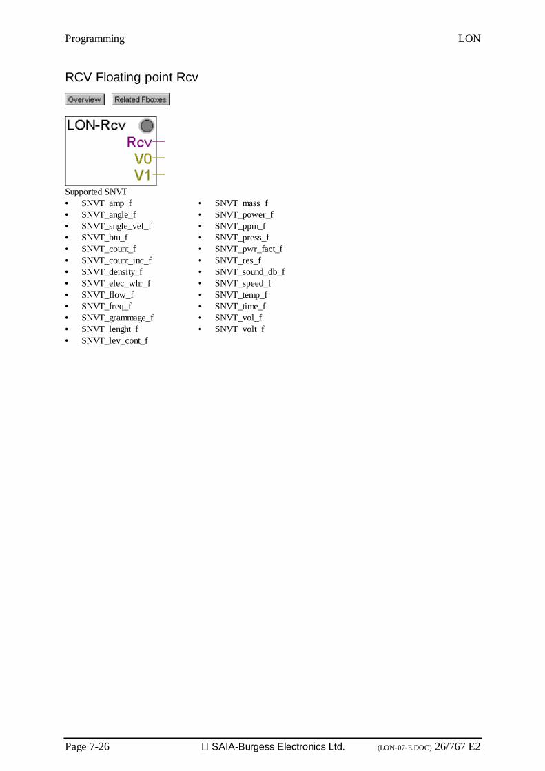
Programming LON
Page 7-26 SAIA-Burgess Electronics Ltd. (LON-07-E.DOC) 26/767 E2
RCV Floating point Rcv
Supported SNVT• SNVT_amp_f• SNVT_angle_f• SNVT_sngle_vel_f• SNVT_btu_f• SNVT_count_f• SNVT_count_inc_f• SNVT_density_f• SNVT_elec_whr_f• SNVT_flow_f• SNVT_freq_f• SNVT_grammage_f• SNVT_lenght_f• SNVT_lev_cont_f
• SNVT_mass_f• SNVT_power_f• SNVT_ppm_f• SNVT_press_f• SNVT_pwr_fact_f• SNVT_res_f• SNVT_sound_db_f• SNVT_speed_f• SNVT_temp_f• SNVT_time_f• SNVT_vol_f• SNVT_volt_f

LON Programming
26/767 E2 (LON-07-E.DOC) SAIA-Burgess Electronics Ltd. Page 7-27
SEND Floating point
Supported SNVT• SNVT_amp_f• SNVT_angle_f• SNVT_sngle_vel_f• SNVT_btu_f• SNVT_count_f• SNVT_count_inc_f• SNVT_density_f• SNVT_elec_whr_f• SNVT_flow_f• SNVT_freq_f• SNVT_grammage_f• SNVT_lenght_f• SNVT_lev_cont_f
• SNVT_mass_f• SNVT_power_f• SNVT_ppm_f• SNVT_press_f• SNVT_pwr_fact_f• SNVT_res_f• SNVT_sound_db_f• SNVT_speed_f• SNVT_temp_f• SNVT_time_f• SNVT_vol_f• SNVT_volt_f
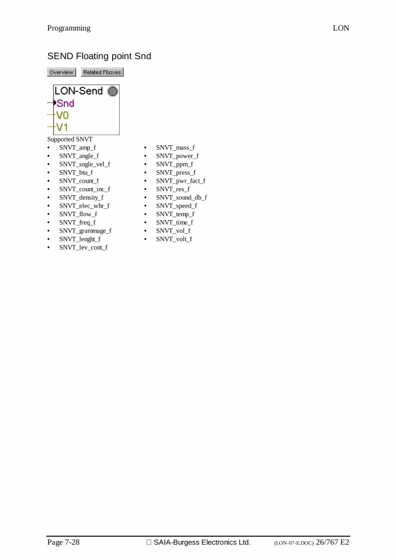
Programming LON
Page 7-28 SAIA-Burgess Electronics Ltd. (LON-07-E.DOC) 26/767 E2
SEND Floating point Snd
Supported SNVT• SNVT_amp_f• SNVT_angle_f• SNVT_sngle_vel_f• SNVT_btu_f• SNVT_count_f• SNVT_count_inc_f• SNVT_density_f• SNVT_elec_whr_f• SNVT_flow_f• SNVT_freq_f• SNVT_grammage_f• SNVT_lenght_f• SNVT_lev_cont_f
• SNVT_mass_f• SNVT_power_f• SNVT_ppm_f• SNVT_press_f• SNVT_pwr_fact_f• SNVT_res_f• SNVT_sound_db_f• SNVT_speed_f• SNVT_temp_f• SNVT_time_f• SNVT_vol_f• SNVT_volt_f
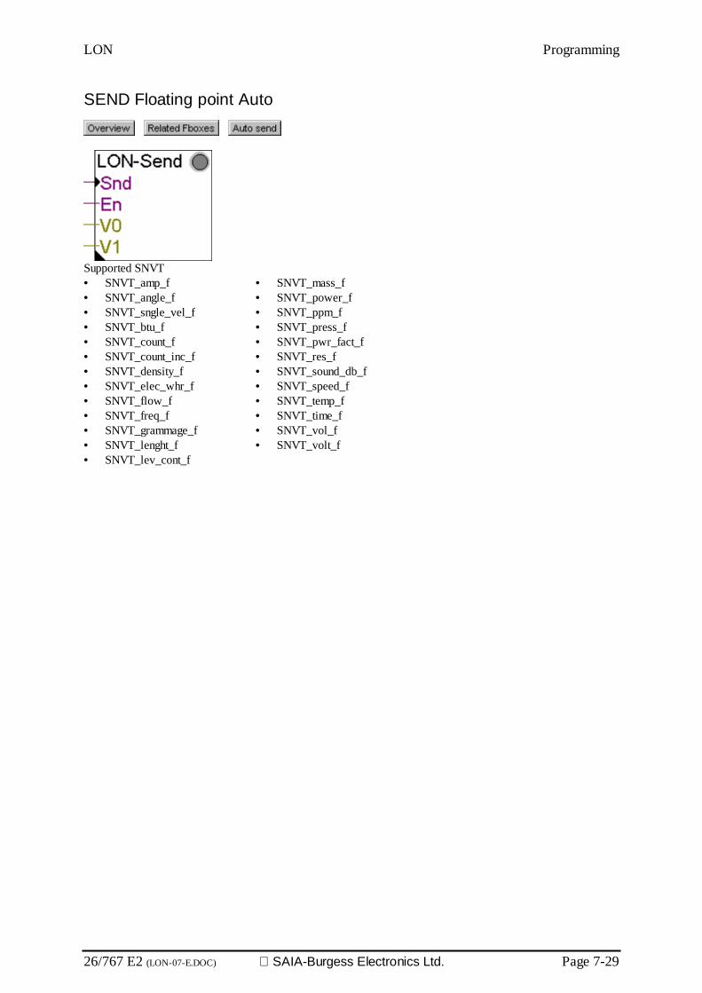
LON Programming
26/767 E2 (LON-07-E.DOC) SAIA-Burgess Electronics Ltd. Page 7-29
SEND Floating point Auto
Supported SNVT• SNVT_amp_f• SNVT_angle_f• SNVT_sngle_vel_f• SNVT_btu_f• SNVT_count_f• SNVT_count_inc_f• SNVT_density_f• SNVT_elec_whr_f• SNVT_flow_f• SNVT_freq_f• SNVT_grammage_f• SNVT_lenght_f• SNVT_lev_cont_f
• SNVT_mass_f• SNVT_power_f• SNVT_ppm_f• SNVT_press_f• SNVT_pwr_fact_f• SNVT_res_f• SNVT_sound_db_f• SNVT_speed_f• SNVT_temp_f• SNVT_time_f• SNVT_vol_f• SNVT_volt_f

Programming LON
Page 7-30 SAIA-Burgess Electronics Ltd. (LON-07-E.DOC) 26/767 E2
Date and Time
RCV Date and Time
Supported SNVT• SNVT_time_stamp
Outputs / LEDRcv Received Set to one for one cycle when new data have been received.YMD Year, Month, Day In PCD format. According the selected option, the PCD clock is
also updated on reception.HMS Hour, Minutes, Seconds In PCD format. According the selected option, the PCD clock is
also updated on reception.LED LED The LED is red in case of reception error.
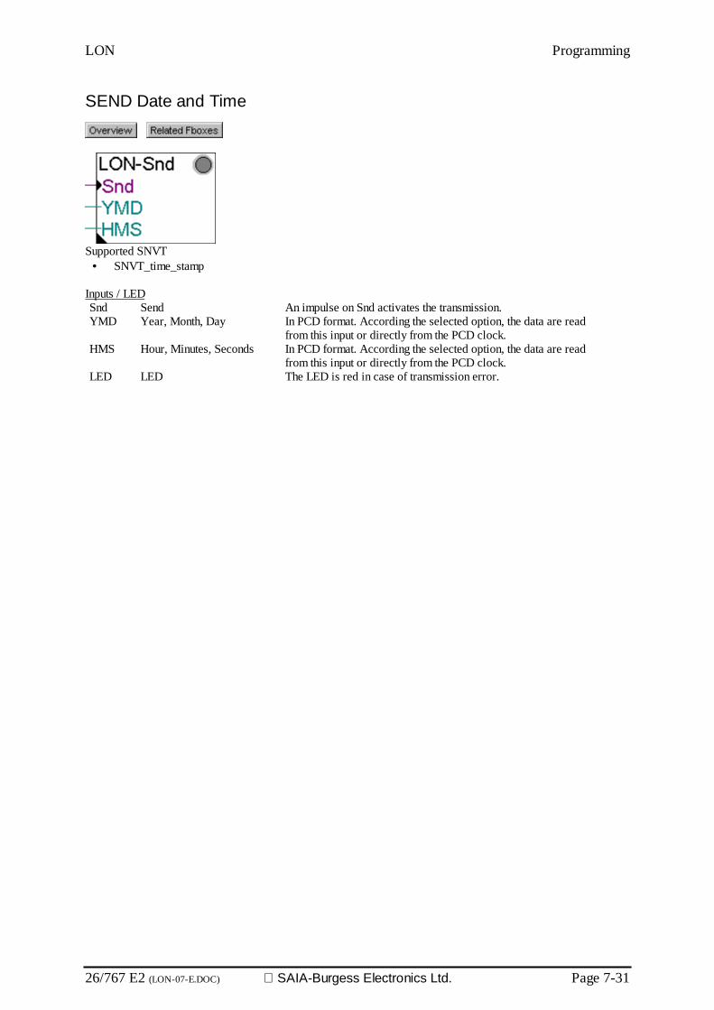
LON Programming
26/767 E2 (LON-07-E.DOC) SAIA-Burgess Electronics Ltd. Page 7-31
SEND Date and Time
Supported SNVT• SNVT_time_stamp
Inputs / LEDSnd Send An impulse on Snd activates the transmission.YMD Year, Month, Day In PCD format. According the selected option, the data are read
from this input or directly from the PCD clock.HMS Hour, Minutes, Seconds In PCD format. According the selected option, the data are read
from this input or directly from the PCD clock.LED LED The LED is red in case of transmission error.
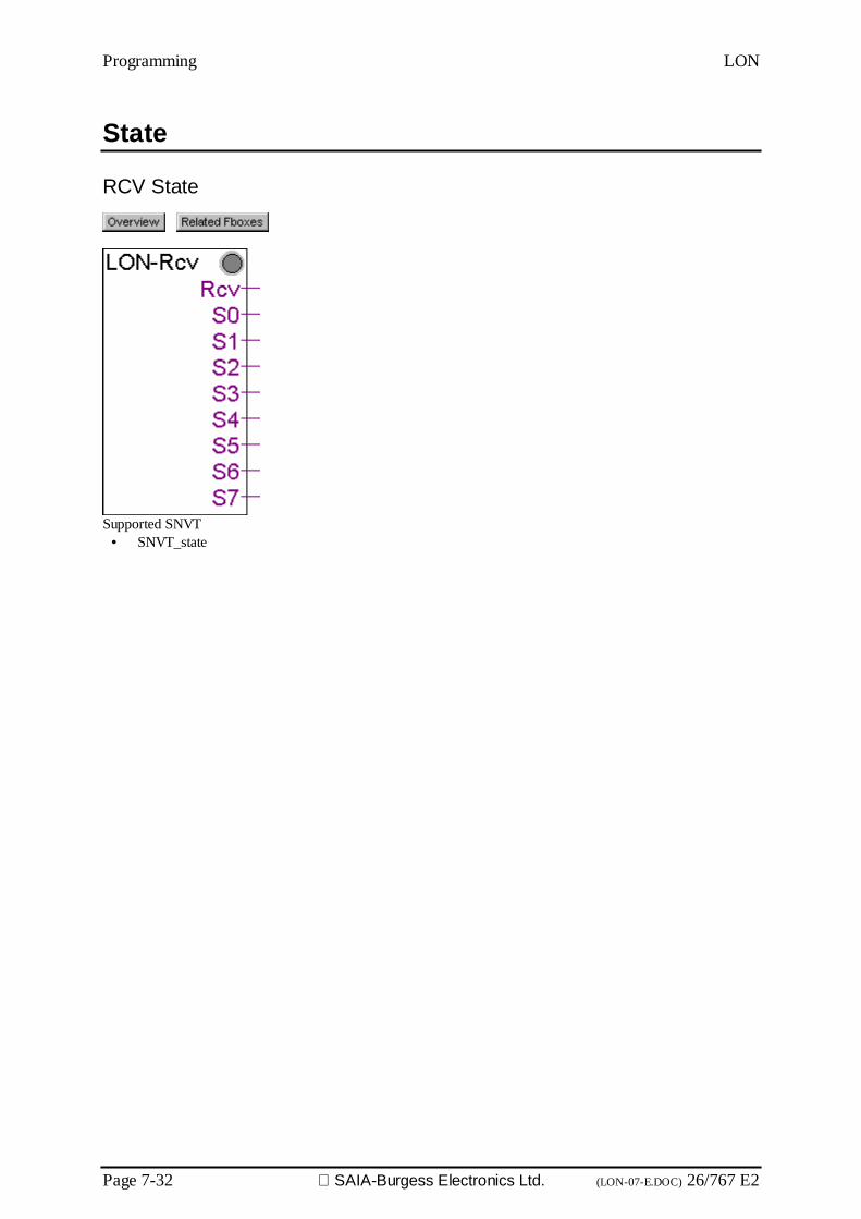
Programming LON
Page 7-32 SAIA-Burgess Electronics Ltd. (LON-07-E.DOC) 26/767 E2
State
RCV State
Supported SNVT• SNVT_state
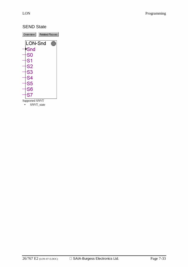
LON Programming
26/767 E2 (LON-07-E.DOC) SAIA-Burgess Electronics Ltd. Page 7-33
SEND State
Supported SNVT• SNVT_state

Programming LON
Page 7-34 SAIA-Burgess Electronics Ltd. (LON-07-E.DOC) 26/767 E2
Alarm
RCV Alarm
Supported SNVT• SNVT_alarm
Outputs / LEDRcv Received Set to one for one cycle when new data have been received.Loc Location 4 bytes on first output and 2 bytes on second output.Id Object IDTyp Alarm typePri Priority levelIdx Index to SNVTVal ValueYMD Year, Month, Day In PCD or LON format according the selected optionHMS Hour, Minutes, Seconds In PCD or LON format according the selected optionMs Mili-secondsLim Alarm limitLED LED The LED is red in case of reception error.
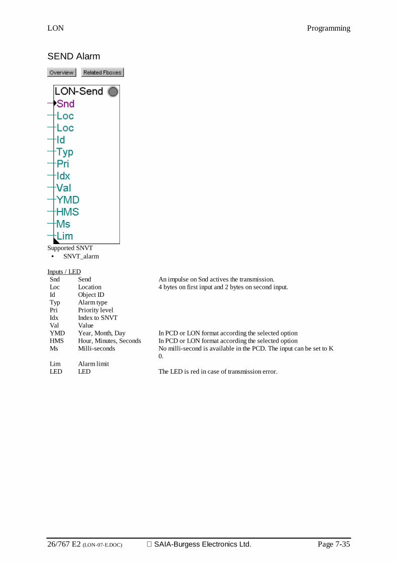
LON Programming
26/767 E2 (LON-07-E.DOC) SAIA-Burgess Electronics Ltd. Page 7-35
SEND Alarm
Supported SNVT• SNVT_alarm
Inputs / LEDSnd Send An impulse on Snd actives the transmission.Loc Location 4 bytes on first input and 2 bytes on second input.Id Object IDTyp Alarm typePri Priority levelIdx Index to SNVTVal ValueYMD Year, Month, Day In PCD or LON format according the selected optionHMS Hour, Minutes, Seconds In PCD or LON format according the selected optionMs Milli-seconds No milli-second is available in the PCD. The input can be set to K
0.Lim Alarm limitLED LED The LED is red in case of transmission error.

Programming LON
Page 7-36 SAIA-Burgess Electronics Ltd. (LON-07-E.DOC) 26/767 E2
Object
RCV Object Status
Supported SNVT• SNVT_obj_status

LON Programming
26/767 E2 (LON-07-E.DOC) SAIA-Burgess Electronics Ltd. Page 7-37
SEND Object Request
Supported SNVT• SNVT_obj_request

Programming LON
Page 7-38 SAIA-Burgess Electronics Ltd. (LON-07-E.DOC) 26/767 E2
Magnetic Cards
RCV Magnetic Cards
Supported SNVT• SNVT_magcrd
Inputs / LEDRcv Received Set to one for one cycle when new data have been received.R0..R4 Register 0 to 4 Registers containing each 4 received bytes. Total 20 bytes.LED LED The LED is red in case of transmission error.

LON Programming
26/767 E2 (LON-07-E.DOC) SAIA-Burgess Electronics Ltd. Page 7-39
SEND Magnetic Cards
Supported SNVT• SNVT_magcrd
Inputs / LEDSnd Send An impulse on Snd actives the transmission.R0..R4 Register 0 to 4 Registers containing each 4 bytes to transmit. Total 20 bytes.LED LED The LED is red in case of transmission error.
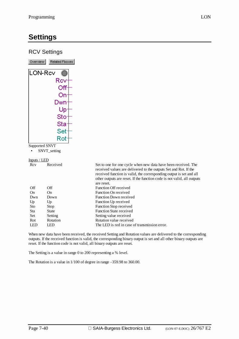
Programming LON
Page 7-40 SAIA-Burgess Electronics Ltd. (LON-07-E.DOC) 26/767 E2
Settings
RCV Settings
Supported SNVT• SNVT_setting
Inputs / LEDRcv Received Set to one for one cycle when new data have been received. The
received values are delivered to the outputs Set and Rot. If thereceived function is valid, the corresponding output is set and allother outputs are reset. If the function code is not valid, all outputsare reset.
Off Off Function Off receivedOn On Function On receivedDwn Down Function Down receivedUp Up Function Up receivedSto Stop Function Stop receivedSta State Function State receivedSet Setting Setting value receivedRot Rotation Rotation value receivedLED LED The LED is red in case of transmission error.
When new data have been received, the received Setting and Rotation values are delivered to the correspondingoutputs. If the received function is valid, the corresponding binary output is set and all other binary outputs arereset. If the function code is not valid, all binary outputs are reset.
The Setting is a value in range 0 to 200 representing a % level.
The Rotation is a value in 1/100 of degree in range –359.98 to 360.00.

LON Programming
26/767 E2 (LON-07-E.DOC) SAIA-Burgess Electronics Ltd. Page 7-41
SEND Settings
Supported SNVT• SNVT_setting
Inputs / LEDOff Off Send the function OffOn On Send the function OnDwn Down Send the function DownUp Up Send the function UpSto Stop Send the function StopSta State Send the function StateSet Setting Setting value to sendRot Rotation Rotation value to sendLED LED The LED is red in case of transmission error.
On a positiv edge at an input, the corresponding function is sent with the setting and rotation value.
The Setting is a value in range 0 to 200 representing a % level.
The Rotation is a value in 1/100 of degree in range –359.98 to 360.00.

Programming LON
Page 7-42 SAIA-Burgess Electronics Ltd. (LON-07-E.DOC) 26/767 E2
Other Fboxes
LON Diagnostics
Optional Fbox showing the diagnostics of the LON Network.
Error indication DescriptionSASI LON Fatal error occurring when the LON channel is assigned.
Usually a FW or hardware problem:- bad PCD firmware- bad LON module firmware- no LON module- defective LON module
Diagnostic Flags Description0 Wink The message 'Wink' is displayed when the station is “Winked”.1 Synchronization This flag is set when a synchronization error occurs at startup or
during program execution.2 Receive diagnostic Set when a reception error occurred. Detail about the error is
displayed in the diagnostic register (bits 0...15) below. The flagwill be automatically reset after the diagnostic register is clearedusing the Clear button below.
3 LON interface reset This flag is set when the LON node is reset.4 New binding New binding information have been loaded in the PCD but a
restart is necessary before uploading the binding informationwith the LON Configurator.
5 Transmission diagnostic Set when a transmission error occurred. Detail about the error isdisplayed in the diagnostic register (bits 16...31) below. The flagwill be automatically reset after the diagnostic register is clearedusing the Clear button below.
6 Interface busy Set during synchronization with the LON-Network. Automaticallyreset when the synchronization is finished.
7 Node Online The display is set to 'Not Online' when information containedinto the LON module is corrupted or when the node is set Offlinefrom the binding tool. When this flag is set it is not possible toupdate or poll SNVT's on the network.When the 'Not Online' message is displayed and the service LEDis blinking regularly, the LON Node Status must be set to 'Con-figured' using the binding tool.
Diagnostic Register DescriptionClear register Button to clear the diagnostics
Reception Description0 LON Interface malfunction Receiving more SNVT than supported. Up to 80 SNVT (receive
and send) can be handled simultaneously.1 Data already on the net Set when the PCD receives a SNVT which was already sent by
the PCD without any acknowledgement from the network.2 NAK received on polling (SRXM) Attempt to poll a SNVT receives a NAK. Probably a binding
problem (No binding, Bad binding), or the LON module is notconnected to the LON network.
3 Not used4 SNVT not defined Set when the PCD tries to send an undefined SNVT. The LON configura-
tion loaded into the PCD doesn’t concern the current LON project, or iscorrupted. The project should be re-built and downloaded into the PCD.

LON Programming
26/767 E2 (LON-07-E.DOC) SAIA-Burgess Electronics Ltd. Page 7-43
If the problem persists please contact SAIA-Burgess.5 SNVT Type not defined Receiving a SNVT of undefined type. The LON configurator is
possibly not up to date.6 SNVT DB is not defined Receiving an update from the network and there is no configura-
tion of the concerned SNVT. The project should be re-built anddownloaded into the PCD.If the problem persists please contact SAIA-Burgess.
7 Diagnostic Error A diagnostic memory has been corrupted, changed, erased or istoo small. The project should be re-built and downloaded intothe PCD.If the problem persists please contact SAIA-Burgess.
8 SNVT size from DB Set when the PCD receives a SNVT from the network, which sizeis bigger than the available memory space reserved in the PCD.Please contact SAIA-Burgess if this problem occurs.
9 SNVT size from network Set when the PCD receives a SNVT from the network, which sizeis different than the size expected by the PCD.Please contact SAIA-Burgess if this problem occurs.
10 .. 15 Not used
Transmission Description16 LON Interface malfunction Sending more SNVT than supported. Up to 80 SNVT (receive and send)
can be handled simultaneously.17 Data already on the net Attempt to send a variable, which was already sent by the PCD
without any acknowledgement from the network.Please contact SAIA-Burgess if this problem occurs.
18 NAK received on update (STXM) NAK received on update (STXM).19 Not used20 SNVT not defined Set when the PCD program tries to send an undefined SNVT. The
LON configuration loaded into the PCD doesn’t concern thecurrent LON project, or is corrupted. The project should be re-built and downloaded into the PCD.If the problem persists please contact SAIA-Burgess.
21 SNVT Type not defined Sending a SNVT of an undefined type. The LON configurator ispossibly not up to date.
22 SNVT DB is not defined Sending a SNVT into the network and there is no configuration ofthe concerned SNVT. The project should be re-built and down-loaded into the PCD.If the problem persists please contact SAIA-Burgess.
23 Diagnostic Error A diagnostic memory has been corrupted, changed, erased or istoo small. The project should be re-built and downloaded intothe PCD.If the problem persists please contact SAIA-Burgess..
24 SNVT size from DB Set when the PCD sends a SNVT onto the network, which size isbigger than the available memory space reserved in the PCD.Please contact SAIA-Burgess if this problem occurs.
25 SNVT size from network Set when the PCD sends a SNVT onto the network, which size isdifferent than the size expected by the PCD.Please contact SAIA-Burgess if this problem occurs.
26 .. 31 Not used
See the LON manual for more details on the diagnostics.
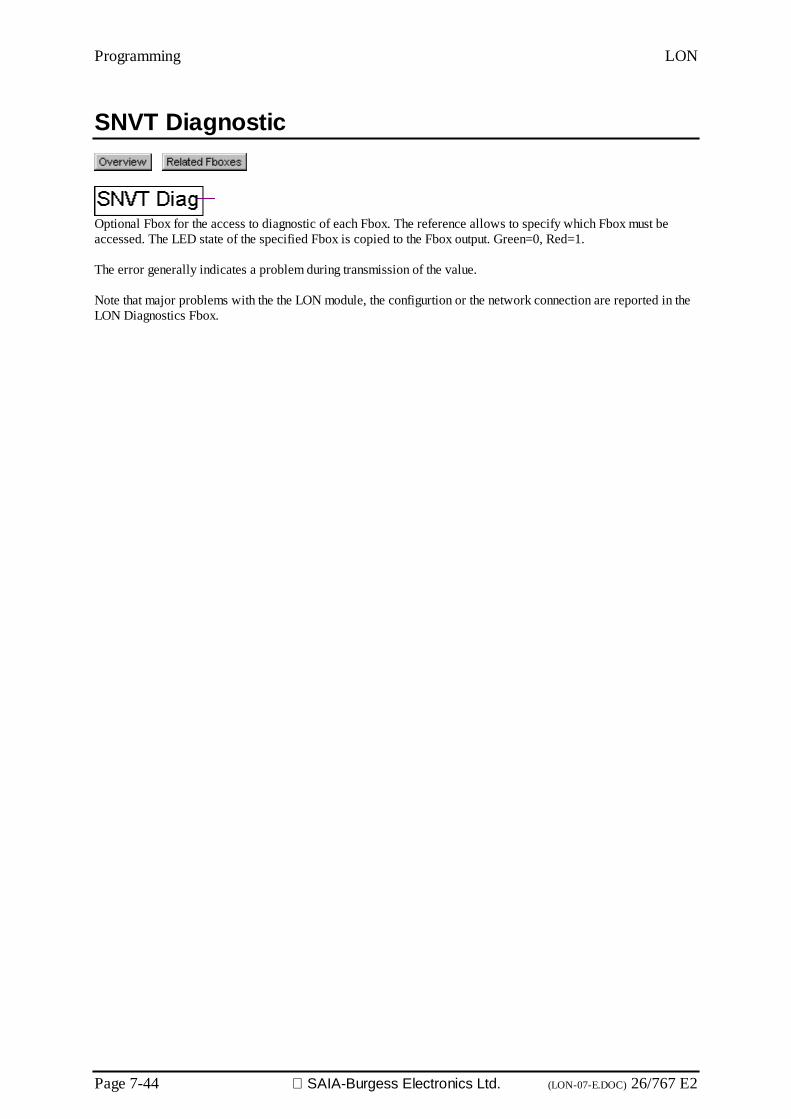
Programming LON
Page 7-44 SAIA-Burgess Electronics Ltd. (LON-07-E.DOC) 26/767 E2
SNVT Diagnostic
Optional Fbox for the access to diagnostic of each Fbox. The reference allows to specify which Fbox must beaccessed. The LED state of the specified Fbox is copied to the Fbox output. Green=0, Red=1.
The error generally indicates a problem during transmission of the value.
Note that major problems with the the LON module, the configurtion or the network connection are reported in theLON Diagnostics Fbox.
LON Configuration for PCDxx7
26/767 E2 (LON-08-E.DOC) SAIA-Burgess Electronics Ltd. Page 8-1
8. Configuring LON parameters for xx7 Series PCDs and LON access with S7.
The PCD can process the data of every LON node in a network. To facili-tate this, the PCD must know which NVs (Network Variables) are avail-able in the node or generally in the network. It is therefore necessary todeclare NVs that are to be used in the PCD
Declaration of NVs for the PCD takes place with SNET32 software for thePCDxx7. Theversion should be V2.1.200 or higher.
When declaration is complete, it is compiled by SNET32 during which asource file (IL) is generated for the SIMATIC S7. This file contains thesource code of 4 data-blocks. They contain all the information on theNVs required for this application.
If initialization of the LON modules is complete, the information in thedata-blocks is transferred to the module. The output NV will then beavailable on the network side. In the final phase, binding of NVs betweenthe nodes can now be carried out.
SIMATIC is a registered trademark of Siemens AG
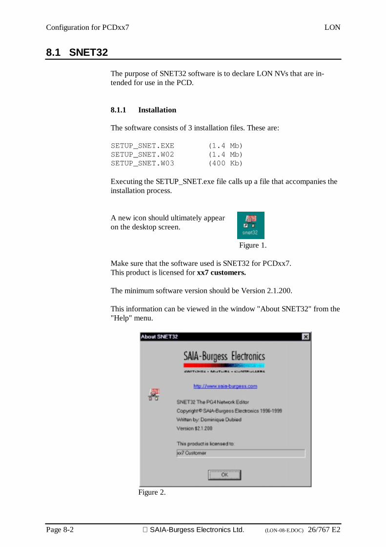
Configuration for PCDxx7 LON
Page 8-2 SAIA-Burgess Electronics Ltd. (LON-08-E.DOC) 26/767 E2
8.1 SNET32
The purpose of SNET32 software is to declare LON NVs that are in-tended for use in the PCD.
8.1.1 Installation
The software consists of 3 installation files. These are:
SETUP_SNET.EXE (1.4 Mb)SETUP_SNET.W02 (1.4 Mb)SETUP_SNET.W03 (400 Kb)
Executing the SETUP_SNET.exe file calls up a file that accompanies theinstallation process.
A new icon should ultimately appearon the desktop screen.
Figure 1.
Make sure that the software used is SNET32 for PCDxx7.This product is licensed for xx7 customers.
The minimum software version should be Version 2.1.200.
This information can be viewed in the window "About SNET32" from the"Help" menu.
Figure 2.
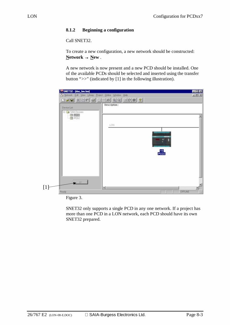
LON Configuration for PCDxx7
26/767 E2 (LON-08-E.DOC) SAIA-Burgess Electronics Ltd. Page 8-3
8.1.2 Beginning a configuration
Call SNET32.
To create a new configuration, a new network should be constructed:Network →→→→ New .
A new network is now present and a new PCD should be installed. Oneof the available PCDs should be selected and inserted using the transferbutton “>>" (indicated by [1] in the following illustration).
Figure 3.
SNET32 only supports a single PCD in any one network. If a project hasmore than one PCD in a LON network, each PCD should have its ownSNET32 prepared.
[1]

Configuration for PCDxx7 LON
Page 8-4 SAIA-Burgess Electronics Ltd. (LON-08-E.DOC) 26/767 E2
8.1.3 Configuring a PCD station
A PCD station can now be configured.
In the "Edit" menu, select "Station Parameters..." or double-click on thesymbol for the PCD station. The following window is displayed:
Figure 4.
This window offers a choice of 3 functions:
Station: The station name, node number and node ID can be de-fined here
Variables: Definition of NVs (Network Variables)See section 2.2 for details.
Options: Function for defining the export options of station con-figuration. See section 2.3 for details.
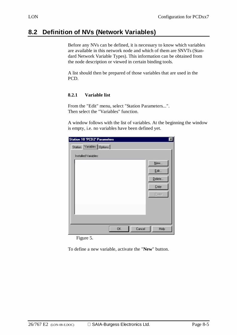
LON Configuration for PCDxx7
26/767 E2 (LON-08-E.DOC) SAIA-Burgess Electronics Ltd. Page 8-5
8.2 Definition of NVs (Network Variables)
Before any NVs can be defined, it is necessary to know which variablesare available in this network node and which of them are SNVTs (Stan-dard Network Variable Types). This information can be obtained fromthe node description or viewed in certain binding tools.
A list should then be prepared of those variables that are used in thePCD.
8.2.1 Variable list
From the "Edit" menu, select "Station Parameters...".Then select the "Variables" function.
A window follows with the list of variables. At the beginning the windowis empty, i.e. no variables have been defined yet.
Figure 5.
To define a new variable, activate the "New" button.

Configuration for PCDxx7 LON
Page 8-6 SAIA-Burgess Electronics Ltd. (LON-08-E.DOC) 26/767 E2
8.2.2 New Variable
If a new variable is generated, the list of possible SNVTs (Standard Net-work Variable Types) is superimposed (as shown in the following figure).
The exact SNVT required should be selected and the "Add..." button thenactivated.
Figure 6.
When the SNVT has been selected and the "Add..." button pressed, thefollowing window is displayed:
Figure 7.
[3]
[2]
[4]
[1]

LON Configuration for PCDxx7
26/767 E2 (LON-08-E.DOC) SAIA-Burgess Electronics Ltd. Page 8-7
Figure 7 shows the characteristics of network variables. These are:
[1] The chosen SNVT generates the variable.
[2] The network variable 'Name'.This name is used later in S7 software for symbolic programming.
[3] This 'Count' is used whenever there are different variables of thesame type, which have the same name and are only distinguishedby having a different index.Example: For variable name 'Switch_Light' Count = 3Switch_Light00Switch_Light01Switch_Light02
[4] 'Direction' defines a variable as PCD input or output data.
All variables required should be declared. The window will then contain alist of all variables that will be available to the S7 program.
Finally, confirm with 'OK'. This completes the definition of network vari-ables.
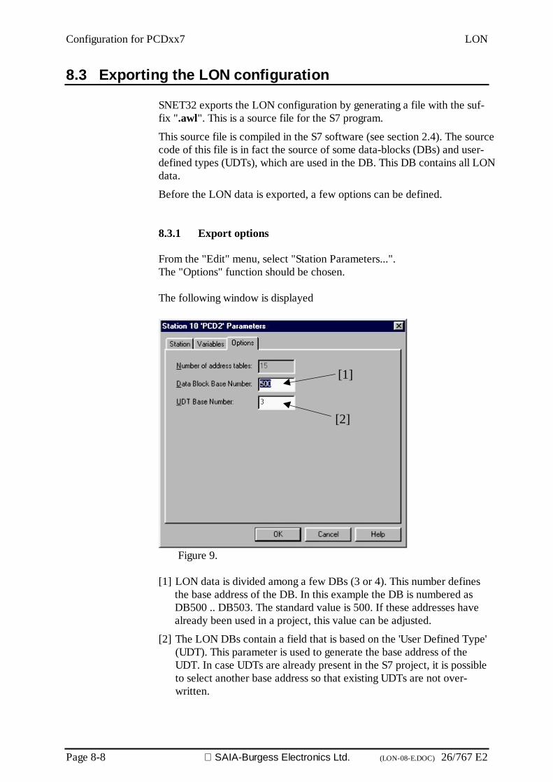
Configuration for PCDxx7 LON
Page 8-8 SAIA-Burgess Electronics Ltd. (LON-08-E.DOC) 26/767 E2
8.3 Exporting the LON configuration
SNET32 exports the LON configuration by generating a file with the suf-fix ".awl". This is a source file for the S7 program.
This source file is compiled in the S7 software (see section 2.4). The sourcecode of this file is in fact the source of some data-blocks (DBs) and user-defined types (UDTs), which are used in the DB. This DB contains all LONdata.
Before the LON data is exported, a few options can be defined.
8.3.1 Export options
From the "Edit" menu, select "Station Parameters...".The "Options" function should be chosen.
The following window is displayed
Figure 9.
[1] LON data is divided among a few DBs (3 or 4). This number definesthe base address of the DB. In this example the DB is numbered asDB500 .. DB503. The standard value is 500. If these addresses havealready been used in a project, this value can be adjusted.
[2] The LON DBs contain a field that is based on the 'User Defined Type'(UDT). This parameter is used to generate the base address of theUDT. In case UDTs are already present in the S7 project, it is possibleto select another base address so that existing UDTs are not over-written.
[1]
[2]

LON Configuration for PCDxx7
26/767 E2 (LON-08-E.DOC) SAIA-Burgess Electronics Ltd. Page 8-9
8.3.2 Creating and exporting the configuration
When the export options have been selected (see section 2.3.1), the ex-port file can be created.
From the "Project" menu, select "Compile file...".
The following window is displayed. This window offers the opportunityof selecting the name and the destination file.
Press the “Save” button
Compilation has been successfully completed and a file with the suffix".awl" has been saved to the chosen directory.

Configuration for PCDxx7 LON
Page 8-10 SAIA-Burgess Electronics Ltd. (LON-08-E.DOC) 26/767 E2
8.4 Importing the configuration under SIMATIC® S7
The following is intended to show the procedure for importing the LONconfiguration to a SIMATIC S7 project. The prior existence of an S7project is assumed.
8.4.1 Importing the source file
In the SIMATIC Manager, the project is selected and the "Source Files"subdirectory is activated.
Then, from the "Insert" menu, the "External Source File..." function isselected. A file browser is displayed. The file with the suffix ".awl"(which contains the LON configuration data) should be selected and up-loaded (see also section 2.3).
The source file is now located in subdirectory "Source file...".
SIMATIC is a registered trademark of Siemens AG

LON Configuration for PCDxx7
26/767 E2 (LON-08-E.DOC) SAIA-Burgess Electronics Ltd. Page 8-11
8.4.2 Compiling the source file
To compile the source file, click on it. Then, from the "File" menu of theSIMATIC Manager, select the "Compile" function.
When compilation has finished, a window is displayed with the result. Noerrors should be indicated.
In the SIMATIC Manager, the subdirectory "Blocks" now includes thedata-block (DB) and the UDT
SIMATIC is a registered trademark of Siemens AG.
Configuration for PCDxx7 LON
Page 8-12 SAIA-Burgess Electronics Ltd. (LON-08-E.DOC) 26/767 E2
8.5 LON access with S7
The accessing of LON network data with the S7 programming environ-ment is achieved by using the information in various data-blocks (DBs) incombination with a System Function Call (SFC).
8.5.1 Data-block information
The data-block can be generated exclusively with SNET32 software, thenimported within the S7 programming environment and compiled.
Depending on the configuration, up to 4 data-blocks (DBs) can occur in asingle project. These DBs have consecutive block addresses. If the blockbase address is 500:
DB500 (base address)configuration data
DB501 (base address +1)Contains the NVs (Network Variables). This DB only exists if severalNVs have been declared.
DB502 (base address +2)Contains the 'Explicit message'. This DB only exists if several 'Explicitmessages' have been declared.
DB503 (base address +3)Contains the diagnostic flags for NVs and explicit messages
8.5.2 Configuration data-block (base address)
This DB contains all the data necessary for initializing the LON interface(PCD7.F80x). The data located in this DB must on no account be modi-fied by the user.

LON Configuration for PCDxx7
26/767 E2 (LON-08-E.DOC) SAIA-Burgess Electronics Ltd. Page 8-13
8.5.3 Network Variable DB (base address +1)
This DB contains all NVs (Network Variables).The NVs are identified by the names they were given during configura-tion with the SNET32 tools.
NVs that have been declared as inputs are given a new value, refreshedby the LON node and written directly into a DB.
For NVs that have been declared as outputs, the value that is to be sent toa LON node should be written to the corresponding NV, after which theSend-SFC should be called.
Data is accessed using symbolic names (see section 3.1.5).
Data Block (base address +1)
8.5.4 Explicit message DB (base address +2)
This DB contains all declared 'Explicit messages'.
It operates in the same way as the NV DB.
Data Block (base address +2)

Configuration for PCDxx7 LON
Page 8-14 SAIA-Burgess Electronics Ltd. (LON-08-E.DOC) 26/767 E2
8.5.5 Diagnostic Flag DB (base address +3)
This DB contains the diagnostics for all NVs and the 'Explicit messages'.
The 'NvDiag' field contains one diagnostic byte for each NV.
The NV diagnostic bytes are listed in the same order as in DB 'NV' (baseaddress +1).
Example: NV 'AI_3' is the third NV in DB 'NV', therefore its diagnosticbyte is the third byte in the 'NvDiag' field, i.e. NvDiag[3].
The same applies for the explicit message, but in the 'MsgDiag' field.
Data Block (base address +3)
The significance of the individual bits is as follows:
Bit 0: If a LON node writes to the corresponding NV (refreshing thevalue), this bit is set high (true). This bit should be reset by the S7software after evaluation.
Bit 1: If a LON node reads the corresponding NV, this bit is set high(true). This bit should be reset by the S7 software after evaluation.

LON Configuration for PCDxx7
26/767 E2 (LON-08-E.DOC) SAIA-Burgess Electronics Ltd. Page 8-15
8.5.6 Working with symbolic names
The simplest method of handling NV diagnostics involves the use of sym-bolic names. However, before any work can take place using the sym-bolic names of NVs, which are located within DBs, the DBs themselvesmust be assigned symbolic names.
To do this, the symbol table must be opened.In the SIMATIC Manager, select the 'S7 Program' subdirectory of thecorresponding PCD and double-click on the 'Symbols' icon.
The symbols of all the corresponding DBs should be entered in the Sym-bol Editor and the symbol table should be saved.
NVs can now be called directly by name.
Example:To read or write a value of the DB that contains the NVsL "lon_Var". switch_l1T "lon_var".led_4
Read a diagnostic byte:L "db_diag".nvdiag[1]
SIMATIC is a registered trademark of Siemens AG
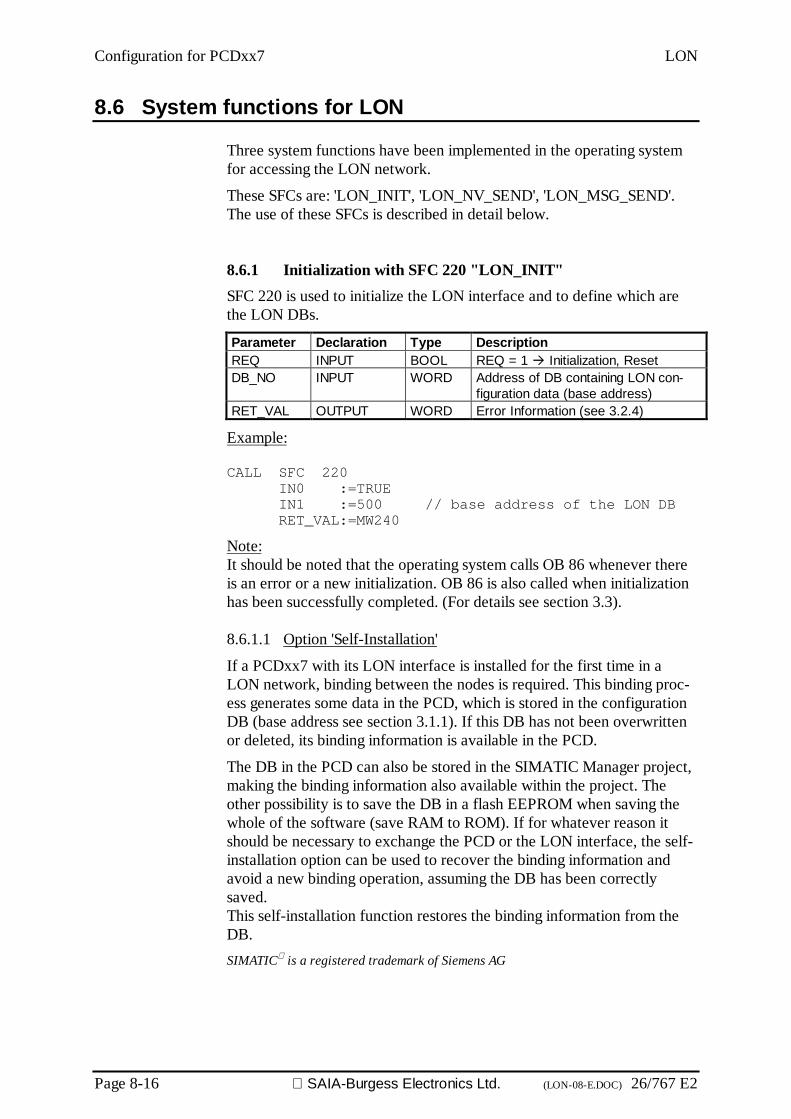
Configuration for PCDxx7 LON
Page 8-16 SAIA-Burgess Electronics Ltd. (LON-08-E.DOC) 26/767 E2
8.6 System functions for LON
Three system functions have been implemented in the operating systemfor accessing the LON network.
These SFCs are: 'LON_INIT', 'LON_NV_SEND', 'LON_MSG_SEND'.The use of these SFCs is described in detail below.
8.6.1 Initialization with SFC 220 "LON_INIT"SFC 220 is used to initialize the LON interface and to define which arethe LON DBs.
Parameter Declaration Type DescriptionREQ INPUT BOOL REQ = 1 Initialization, ResetDB_NO INPUT WORD Address of DB containing LON con-
figuration data (base address)RET_VAL OUTPUT WORD Error Information (see 3.2.4)
Example:
CALL SFC 220IN0 :=TRUEIN1 :=500 // base address of the LON DBRET_VAL:=MW240
Note:It should be noted that the operating system calls OB 86 whenever thereis an error or a new initialization. OB 86 is also called when initializationhas been successfully completed. (For details see section 3.3).
8.6.1.1 Option 'Self-Installation'
If a PCDxx7 with its LON interface is installed for the first time in aLON network, binding between the nodes is required. This binding proc-ess generates some data in the PCD, which is stored in the configurationDB (base address see section 3.1.1). If this DB has not been overwrittenor deleted, its binding information is available in the PCD.
The DB in the PCD can also be stored in the SIMATIC Manager project,making the binding information also available within the project. Theother possibility is to save the DB in a flash EEPROM when saving thewhole of the software (save RAM to ROM). If for whatever reason itshould be necessary to exchange the PCD or the LON interface, the self-installation option can be used to recover the binding information andavoid a new binding operation, assuming the DB has been correctlysaved.This self-installation function restores the binding information from theDB.SIMATIC is a registered trademark of Siemens AG

LON Configuration for PCDxx7
26/767 E2 (LON-08-E.DOC) SAIA-Burgess Electronics Ltd. Page 8-17
The use of this self-installation option requires the field for the DB to beconfigured with a predefined value. The field in the DB is'Header.SelfInstFlag', the value to be set is 'B#16#FF'
This configuration must take place before the SFC220 call "Init_LON".
Example:
L B#16#FFT DB500.DBB24
CALL SFC220IN0 :=TRUEIN1 :=500RET_VAL :=MW240
8.6.1.2 Diagnostic possibilities of binding information
If for whatever reason (e.g. addition of NVs) it should be necessary toperform a new binding operation on the PCD system, the LEDs on theLON interface will flash to indicate the change.
The new binding operation also changes the information in the DB, so thatwhat is stored on the flash EEPROM or in the file is no longer current. Toavoid all these problems, the system reports a binding change by setting thefield 'Header.LonCfgChanged' (DBB25) of the configuration DB to thevalue 'b#16#FF'. When the value returns to 'b#16#00' the LED will stopflashing.
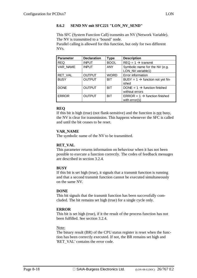
Configuration for PCDxx7 LON
Page 8-18 SAIA-Burgess Electronics Ltd. (LON-08-E.DOC) 26/767 E2
8.6.2 SEND NV mit SFC221 "LON_NV_SEND"
This SFC (System Function Call) transmits an NV (Network Variable).The NV is transmitted to a ‘bound’ node.Parallel calling is allowed for this function, but only for two differentNVs.
Parameter Declaration Type DescriptionREQ INPUT BOOL REQ = 1 transmitVAR_NAME INPUT ANY Symbolic name for the NV (e.g.
LON_NV.variable1)RET_VAL OUTPUT WORD Error informationBUSY OUTPUT BIT BUSY = 1 function not yet fin-
ishedDONE OUTPUT BIT DONE = 1 function finished
without errorsERROR OUTPUT BIT ERROR = 1 function finished
with error(s)
REQIf this bit is high (true) (not flank-sensitive) and the function is not busy,the NV is clear for transmission. This happens whenever the SFC is calledand until the bit ceases to be reset.
VAR_NAMEThe symbolic name of the NV to be transmitted.
RET_VALThis parameter returns information on behaviour when it has not beenpossible to execute a function correctly. The codes of feedback messagesare described in section 3.2.4.
BUSYIf this bit is set high (true), it signals that a transmit function is runningand that a second transmit function cannot be executed simultaneouslyon the same NV.
DONEThis bit signals that the transmit function has been successfully com-cluded. The bit remains set high (true) for a single cycle only.
ERRORThis bit is set high (true), if it the result of the process function has notbeen fulfilled. See section 3.2.4.
Note:The binary result (BR) of the CPU status register is reset when the func-tion has been correctly executed. If not, the BR remains set high and'RET_VAL' contains the error code.
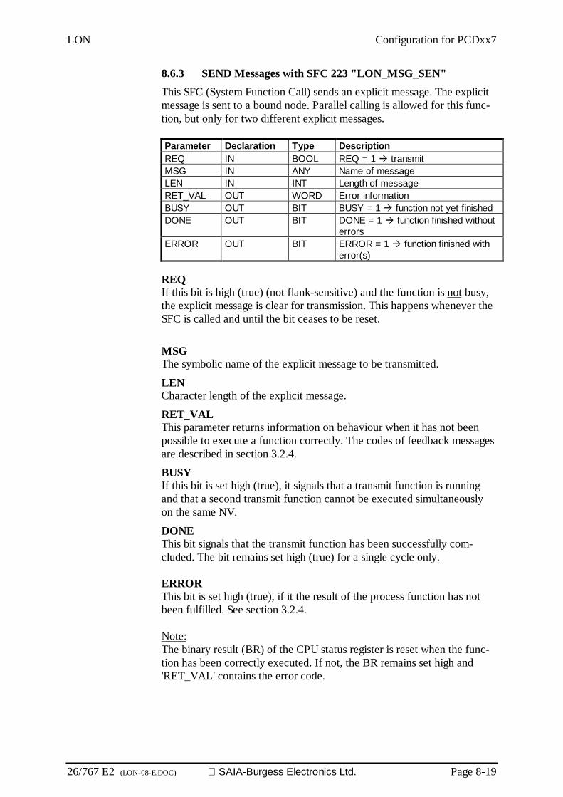
LON Configuration for PCDxx7
26/767 E2 (LON-08-E.DOC) SAIA-Burgess Electronics Ltd. Page 8-19
8.6.3 SEND Messages with SFC 223 "LON_MSG_SEN"This SFC (System Function Call) sends an explicit message. The explicitmessage is sent to a bound node. Parallel calling is allowed for this func-tion, but only for two different explicit messages.
Parameter Declaration Type DescriptionREQ IN BOOL REQ = 1 transmitMSG IN ANY Name of messageLEN IN INT Length of messageRET_VAL OUT WORD Error informationBUSY OUT BIT BUSY = 1 function not yet finishedDONE OUT BIT DONE = 1 function finished without
errorsERROR OUT BIT ERROR = 1 function finished with
error(s)
REQIf this bit is high (true) (not flank-sensitive) and the function is not busy,the explicit message is clear for transmission. This happens whenever theSFC is called and until the bit ceases to be reset.
MSGThe symbolic name of the explicit message to be transmitted.
LENCharacter length of the explicit message.
RET_VALThis parameter returns information on behaviour when it has not beenpossible to execute a function correctly. The codes of feedback messagesare described in section 3.2.4.
BUSYIf this bit is set high (true), it signals that a transmit function is runningand that a second transmit function cannot be executed simultaneouslyon the same NV.
DONEThis bit signals that the transmit function has been successfully com-cluded. The bit remains set high (true) for a single cycle only.
ERRORThis bit is set high (true), if it the result of the process function has notbeen fulfilled. See section 3.2.4.
Note:The binary result (BR) of the CPU status register is reset when the func-tion has been correctly executed. If not, the BR remains set high and'RET_VAL' contains the error code.

Configuration for PCDxx7 LON
Page 8-20 SAIA-Burgess Electronics Ltd. (LON-08-E.DOC) 26/767 E2
8.6.4 Error Code
All SFCs described above reset the "BR" bit (Binary Result) of the CPUstatus register when the function has been executed without errors. If anerror occurred, the "BR" bit would be set and 'RET_VAL' would containa value describing that error. Some of these messages are standard S7 er-ror codes, others have been added for xx7 LON.
BUSY DONE ERROR BR RET_VAL Description0 0 0 0 0x7000 First call with REQ = 0, no
data transfer1 0 0 0 0x7001 First call with REQ = 1,
data transfer starts1 0 0 0 0x7002 Interim call (REQ irrelevant)
Data transfer already active0 1 0 0 0x0000 Data transfer successfully
executed0 0 1 0 0x0001 LON interface not working
correctly0 0 1 0 0x0002 Job cannot be executed at
present0 0 1 0 0x4000 Data transfer not successful0 0 1 1 0xFFFF Job could not be fulfilled be-
cause too little (internal) mem-ory is available.Try again later!
0 0 1 1 0xFFFE The NV specified could not befound.
0 0 1 1 0xFFFD Error in LON configuration DB0 0 1 1 0xFFFC The LON driver has not yet
been initialized.0 0 1 1 0xFFFB DB address of variables does
not match initialization0 0 1 1 0xFFFA Message too long!0 0 1 1 0x803A The DB specified (e.g.the
SNVT-DB) could not be found0 0 1 1 0x8022 The DB does not contain the
SNVT or the message(DB length error)
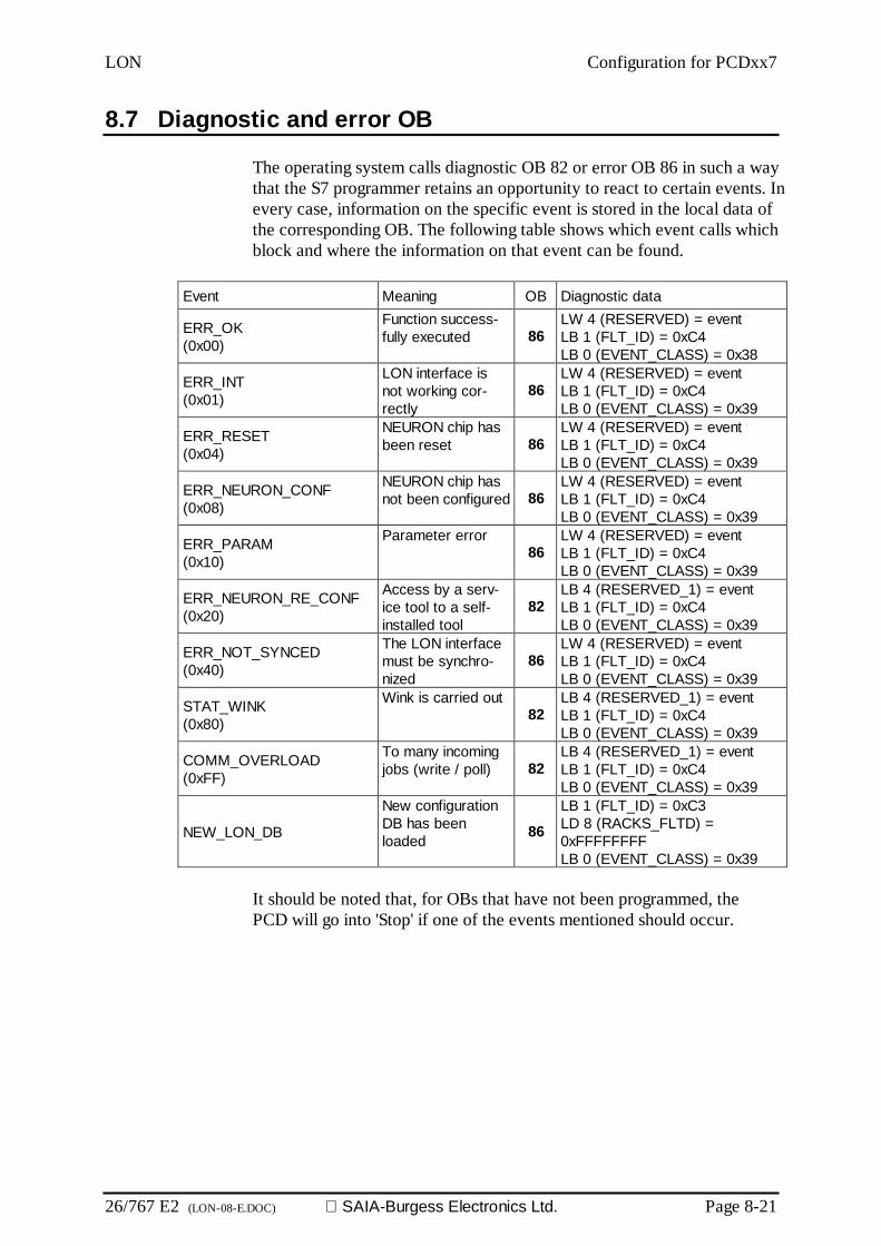
LON Configuration for PCDxx7
26/767 E2 (LON-08-E.DOC) SAIA-Burgess Electronics Ltd. Page 8-21
8.7 Diagnostic and error OB
The operating system calls diagnostic OB 82 or error OB 86 in such a waythat the S7 programmer retains an opportunity to react to certain events. Inevery case, information on the specific event is stored in the local data ofthe corresponding OB. The following table shows which event calls whichblock and where the information on that event can be found.
Event Meaning OB Diagnostic data
ERR_OK(0x00)
Function success-fully executed 86
LW 4 (RESERVED) = eventLB 1 (FLT_ID) = 0xC4LB 0 (EVENT_CLASS) = 0x38
ERR_INT(0x01)
LON interface isnot working cor-rectly
86LW 4 (RESERVED) = eventLB 1 (FLT_ID) = 0xC4LB 0 (EVENT_CLASS) = 0x39
ERR_RESET(0x04)
NEURON chip hasbeen reset 86
LW 4 (RESERVED) = eventLB 1 (FLT_ID) = 0xC4LB 0 (EVENT_CLASS) = 0x39
ERR_NEURON_CONF(0x08)
NEURON chip hasnot been configured 86
LW 4 (RESERVED) = eventLB 1 (FLT_ID) = 0xC4LB 0 (EVENT_CLASS) = 0x39
ERR_PARAM(0x10)
Parameter error86
LW 4 (RESERVED) = eventLB 1 (FLT_ID) = 0xC4LB 0 (EVENT_CLASS) = 0x39
ERR_NEURON_RE_CONF(0x20)
Access by a serv-ice tool to a self-installed tool
82LB 4 (RESERVED_1) = eventLB 1 (FLT_ID) = 0xC4LB 0 (EVENT_CLASS) = 0x39
ERR_NOT_SYNCED(0x40)
The LON interfacemust be synchro-nized
86LW 4 (RESERVED) = eventLB 1 (FLT_ID) = 0xC4LB 0 (EVENT_CLASS) = 0x39
STAT_WINK(0x80)
Wink is carried out82
LB 4 (RESERVED_1) = eventLB 1 (FLT_ID) = 0xC4LB 0 (EVENT_CLASS) = 0x39
COMM_OVERLOAD(0xFF)
To many incomingjobs (write / poll) 82
LB 4 (RESERVED_1) = eventLB 1 (FLT_ID) = 0xC4LB 0 (EVENT_CLASS) = 0x39
NEW_LON_DB
New configurationDB has beenloaded 86
LB 1 (FLT_ID) = 0xC3LD 8 (RACKS_FLTD) =0xFFFFFFFFLB 0 (EVENT_CLASS) = 0x39
It should be noted that, for OBs that have not been programmed, thePCD will go into 'Stop' if one of the events mentioned should occur.

Configuration for PCDxx7 LON
Page 8-22 SAIA-Burgess Electronics Ltd. (LON-08-E.DOC) 26/767 E2
8.8 Restrictions
Due to system boundaries, some restrictions should be noted regardingthe use of the LON interface.
As soon as the LON interface has been initialized with SFC 220, S7memory cannot be compressed with the PCD in RUN.
The number of simultaneous functions for SENDING NV when usingSFC 221 is limited to 15.

LON Commissioning, example and debugging
26/767 E2 (LON-09-E.DOC) SAIA-Burgess Electronics Ltd. Page 9-1
9. Commissioning and debuggingWhen constructing a LON project various difficulties may arise. Some ofthese points are listed in the present section with the intention of helpingthe FUPLA programmer find a solution.
Minimum requirements for constructing a LON project:
• LON module F80x• PCD2 from hardware index 'J' with min. 4 MB internal RAM• Firmware with LON capability for PCD1 or PCD2• PG4 with LON functions (from 2.0 with spec. SNET)• PG4 and firmware must therefore be appropriate for LON
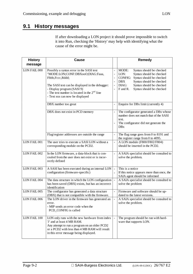
Commissioning, example and debugging LON
Page 9-2 SAIA-Burgess Electronics Ltd. (LON-09-E.DOC) 26/767 E2
9.1 History messages
If after downloading a LON project it should prove impossible to switchit into Run, checking the 'History' may help with identifying what thecause of the error might be.
Historymessage
Cause Remedy
Possibly a syntax error in the SASI text"MODE:LON;CONF:DBXooO;DIAG:Faaa,Fbbb,Fccc,Rddd;
The SASI text can be displayed in the debugger:- Display program (SASI 9)- The text number is located in the 2nd line- Text xxx can now be displayed
------
MODE: Syntax should be checkedLON: Syntax should be checkedCONFIG: Syntax should be checkedDBX Syntax should be checkedDIAG: Syntax should be checkedF and R. Syntax should be checked
DBX number too great - Enquire for DBx limit (currently 4)
DBX does not exist in PCD memory -
-
The configurator generated a DBx whosenumber does not match that of the SASItext.The configurator did not generate theDBx
LON FAIL 000
Flag/register addresses are outside the range - The flag range goes from 0 to 8191 andthe register range from 0 to 4095.
LON FAIL 001 The user tries to execute a SASI LON without acorresponding module on the PCD2.
- A LON module (F800/F802/F804)should be inserted in the PCD2.
LON FAIL 002 In the LON firmware, a data-block that is con-cealed from the user does not exist or is incor-rectly defined
- A SAIA specialist should be consulted tosolve the problem.
LON FAIL 003 A SASI has been executed during an internal LONconfiguration (firmware-specific)
--
This is a noticeIf this notice appears more than once, theSAIA agent should be informed
LON FAIL 004 The data structure in which the LON configurationhas been saved (DBX) exists, but has an incorrectidentification
- A SAIA specialist should be consulted tosolve the problem
LON FAIL 005 The configurator has generated a data structure(DBX) that is not compatible with the firmware.
- Firmware and software should be up-dated to the latest versions.
LON FAIL 006 The LON driver in the firmware has generated anerror.- MIP sends an error code when the PCD_CONFIG is called
- A SAIA specialist should be consulted tosolve the problem.
LON FAIL 100 LON only runs with the new hardware from index'J' and at least 4 MB RAM.Any attempt to run a program on an older PCD2or a PCD2 with less than 4 MB RAM will resultin this error message being displayed.
- The program should be run with hard-ware that supports LON.

LON Commissioning, example and debugging
26/767 E2 (LON-09-E.DOC) SAIA-Burgess Electronics Ltd. Page 9-3
These errors mainly concern programming in IL. When LON FBoxes inFUPLA are used, perfect operation is guaranteed for correct application.

Commissioning, example and debugging LON
Page 9-4 SAIA-Burgess Electronics Ltd. (LON-09-E.DOC) 26/767 E2
9.2 Additional information about LON with SAIA PCD
Instructions for binding network variables:
Each LON node (neuron chip) has available only one address table withmax. 15 entries. This also applies for the neuron chip on the PCD6.F8xxcard, i.e. a node can address directly a maximum of 15 other nodes.However, this restriction can be lifted via the connection option in the in-stallation tool.
Depending on the type of connection for network variables, there are dif-ferent types of connection entries in this table. If communication fromthe PCD is to be with as many other nodes as possible, we recommendthe ‘broadcast’ type of connection.
If a connection is established with a binding tool between two nodes viathe network variables, the following options should be set:
Broadcast, unacknowledged orBroadcast, unacknowledged, repeated (higher bus load)
With a normal connection option, the entries in the node address tablesare generally made by the binding tool with the 'SubNet/Node' or 'Group'options.
Connection option Intended applicationSubNet / Node Node A transmits to node BGroup Node A transmits to nodes B, C and ... XBroadcast Node A transmits to all nodes in the subnet
The 'Group' connection option is used automatically by many bindingtools when a network variable is to be transmitted from one node to sev-eral others.

LON Commissioning, example and debugging
26/767 E2 (LON-09-E.DOC) SAIA-Burgess Electronics Ltd. Page 9-5
Example for a LON network with normal connection options:
NODE A:Address tableIndex Type Domain Mbr/Nod Rpt tmr Retries Rcv tmr Tx tmr Grp/Sbnt0 Sb/Nd 0 7 32 3 128 96 11 Gpsz 3 0 0 32 3 768 96 02 Unused 0 0 16 0 128 16 03..13 Unused 0 0 16 0 128 16 014 Unused 0 0 16 0 128 16 0
Domain tableIndex Size Subnet Node Auth Key Domn ID0 1 1 3 FF FF FF FF FF FF 01
Variable tableIndex Selctr Dir Prio Auth Addridx Service TrnArnd1 0002 out no no 0 Ackd no2 0003 out no no 0 Ackd no5 0004 out no no 1 Ackd no
PCD:Address tableIndex Type Domain Mbr/Nod Rpt tmr Retries Rcv tmr Tx tmr Grp/Sbnt0 Sb/Nd 0 3 32 3 128 96 11 Sb/Nd 0 2 32 3 128 96 12 Gpsz 3 0 1 32 3 768 96 03..13 Unused 0 0 16 0 128 16 014 Unused 0 0 16 0 128 16 0
Domain tableIndex Size Subnet Node Auth Key Domn ID0 1 1 7 FF FF FF FF FF FF 01
Variable tableIndex Selctr Dir Prio Auth Addridx Service TrnArnd0 0000 out no no 0 Ackd no3 0001 out no no 0 Ackd no7 0005 out no no 1 Ackd no8 0006 out no no 1 Ackd no9 000E out no no 1 Ackd no16 000C out no no 1 Ackd no17 000B out no no 1 Ackd no
NODE B:Address tableIndex Type Domain Mbr/Nod Rpt tmr Retries Rcv tmr Tx tmr Grp/Sbnt0 Sb/Nd 0 7 32 3 128 96 11 Gpsz 3 0 2 32 3 768 96 02 Unused 0 0 16 0 128 16 03..13 Unused 0 0 16 0 128 16 014 Unused 0 0 16 0 128 16 0
Domain tableIndex Size Subnet Node Auth Key Domn ID0 1 1 2 FF FF FF FF FF FF 01
Variable tableIndex Selctr Dir Prio Auth Addridx Service TrnArnd28 000F out no no 0 Ackd no77 0010 out no no 0 Ackd no110 000D out no no 0 Ackd no

Commissioning, example and debugging LON
Page 9-6 SAIA-Burgess Electronics Ltd. (LON-09-E.DOC) 26/767 E2
The following connection structure can be read from the tables:
• Node A transmits variables 1 and 2 to the PCD and variable 5 to nodeB and die PCD.
• The PCD transmits variables 0 and 3 to node A and variables 7,8,9,16and 17 to node B.
• Node B transmits variables 28, 77 and 110 to the PCD.
Representation of input variables has been dispensed with because, as arule, only output variables need an address entry.
For all three nodes the common group address 3 has been entered in theaddress table, although only node A transmits anything across this con-nection. With group addresses it is necessary in each node of the group tomake an entry in the address table, so that it can receive the data trans-mitted.
In the case of the PCD, this example has used a total of 3 lines in the ad-dress table. If one were now to add two further type A nodes, binding in thesame way with the PCD and node B, the address table in the PCD’s LONnode would quickly be full.
Meaning of tables in the LON node:
Table Meaning LinesAddress table List of usable connections 15Domain table Node’s own address as SubNet / Node 1Variable table List of all own network variables and the con-
nection via which they should be transmitted.normal: 634096*) for
PCD
*) The table of variables is extended to 4096 by the MIP host node.
PCDSubnet 1, Node 7
Group, Member 1
Variable index 0Variable index 3Variable index 7Variable index 8Variable index 9Variable index 16Variable index 17
Node ASubnet 1, Node 3
Group 3, Member 0
Variable index 1Variable index 2Variable index 5
Node BSubnet 1, Node 2
Group, member 2
Variable index 28Variable index 77Variable index 110
Connection 0Subnet 1, Node 3
Connection 0Subnet 1, Node 7
Connection 1Group 3
Connection 1Subnet 1, Node 2
Connection 0Subnet 1, Node 7

LON Commissioning, example and debugging
26/767 E2 (LON-09-E.DOC) SAIA-Burgess Electronics Ltd. Page 9-7
Effects of the 'Broadcast' connection option on binding:
NODE A:Address tableIndex Type Domain Mbr/Nod Rpt tmr Retries Rcv tmr Tx tmr Grp/Sbnt0 Unused 0 0 16 0 128 16 01 Unused 0 0 16 0 128 16 02 Bcast 0 0 32 3 128 96 13 Unused 0 0 16 0 128 16 04..14 Unused 0 0 16 0 128 16 0
Domain tableIndex Size Subnet Node Auth Key Domn ID0 1 1 3 FF FF FF FF FF FF 01
Variable tableIndex Selctr Dir Prio Auth Addridx Service TrnArnd1 0013 out no no 2 Rep'td no2 0014 out no no 2 Rep'td no5 0015 out no no 2 Rep'td no
PCD:Address tableIndex Type Domain Mbr/Nod Rpt tmr Retries Rcv tmr Tx tmr Grp/Sbnt0 Unused 0 0 16 0 128 16 01 Unused 0 0 16 0 128 16 02 Unused 0 0 16 0 128 16 03 Bcast 0 0 32 3 128 96 14..14 Unused 0 0 16 0 128 16 0
Domain tableIndex Size Subnet Node Auth Key Domn ID0 1 1 7 FF FF FF FF FF FF 01
Variable tableIndex Selctr Dir Prio Auth Addridx Service TrnArnd0 0011 out no no 3 Rep'td no3 0012 out no no 3 Rep'td no7 0016 out no no 3 Rep'td no8 0017 out no no 3 Rep'td no9 001B out no no 3 Rep'td no16 0018 out no no 3 Rep'td no17 0019 out no no 3 Rep'td no
NODE B:Address tableIndex Type Domain Mbr/Nod Rpt tmr Retries Rcv tmr Tx tmr Grp/Sbnt0 Unused 0 0 16 0 128 16 01 Bcast 0 0 32 3 128 96 12 Unused 0 0 16 0 128 16 03 Unused 0 0 16 0 128 16 04..15 Unused 0 0 16 0 128 16 0
Domain tableIndex Size Subnet Node Auth Key Domn ID0 1 1 2 FF FF FF FF FF FF 01
Variable tableIndex Selctr Dir Prio Auth Addridx Service TrnArnd28 001C out no no 1 Rep'td no77 001D out no no 1 Rep'td no110 001A out no no 1 Rep'td no
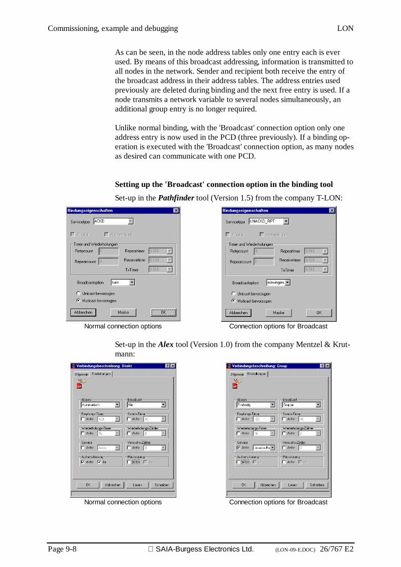
Commissioning, example and debugging LON
Page 9-8 SAIA-Burgess Electronics Ltd. (LON-09-E.DOC) 26/767 E2
As can be seen, in the node address tables only one entry each is everused. By means of this broadcast addressing, information is transmitted toall nodes in the network. Sender and recipient both receive the entry ofthe broadcast address in their address tables. The address entries usedpreviously are deleted during binding and the next free entry is used. If anode transmits a network variable to several nodes simultaneously, anadditional group entry is no longer required.
Unlike normal binding, with the 'Broadcast' connection option only oneaddress entry is now used in the PCD (three previously). If a binding op-eration is executed with the 'Broadcast' connection option, as many nodesas desired can communicate with one PCD.
Setting up the 'Broadcast' connection option in the binding tool
Set-up in the Pathfinder tool (Version 1.5) from the company T-LON:
Normal connection options Connection options for Broadcast
Set-up in the Alex tool (Version 1.0) from the company Mentzel & Krut-mann:
Normal connection options Connection options for Broadcast

LON Terminology, abbreviations, register of sources
26/767 E2 (LON-10-E.DOC) SAIA-Burgess Electronics Ltd. Page 10-1
10. Terminology, abbreviations, register ofsources
10.1 Terminology
3120 NEURON-Chip 3120. Chip from MOTOROLA /TOSHIBA with internal EEPROM, RAM and in-tegral LON interface for network communicationat OSI Layer 7.
3150 NEURON-Chip 3150. Chip from MOTOROLA /TOSHIBA with internal EEPROM and externalEPROM and integral LON interface for networkcommunication at OSI Layer 7.
Address table A table in a neuron chip, defining the group af-filiation of a node and the transmitting address ofa bound network variable. On one neuron chip 15different address tables can be defined.
Alias network variableA secondary place in a network variable tablethat references a 'primary netvar'. An alias net-work variable is controlled parallel to the primaryNV and facilitates the multiple linking of data(e.g. Reset-Kdo via Group-Address, normal Kdosvia Subnet/Node Address).
Application Image The application program that can run on a neuronchip.
Application Layer Layer of transmission that guarantees applicationlevel compatibility. See also under OSI Layer 1-7.
Application message An 'Explicit Message' with a message code be-tween 0x00 and 0x3e (62d). Interpretation of thecode is left to the application.
Binder A software tool that can connect network vari-ables or 'msg_tags'.
Binding The process that defines the connection betweennodes.
Terminology, abbreviations, register of sources LON
Page 10-2 SAIA-Burgess Electronics Ltd. (LON-10-E.DOC) 26/767 E2
Bridge Router with two NEURON chips, which maps themessages from max. 2 domains to both sides.
Broadcast Addressing mode that reaches all nodes simulta-neously within a subnet or domain.
Channel Physical part of LON bus, e.g. between 2 routers
Cloned_domain The domain of several nodes whosemust_be_one bit has been set at 0. Acloned_domain is only used in exceptional casesand does not correspond to LONMARK’s'interoperability guidelines'. In a cloned_domainsubnet/node addressing can no longer be used.werden. 'Broadcast' and 'NeuronID' addressingare used when working in such domains.
Cloned_node A node whose must_be_one bit has been set at0. It is able to receive messages from nodes oper-ating with the same subnet/node address. It is setduring export of the MIP on the LON-Builder orby the update_clone_domain function.
Configuration network variableA special class of network variable that allows anapplication’s configuration data to be saved. Con-figuration data are always input variables, beingstored in EEPROM. With 'host based nodes' thehost must ensure that data is stored in a non-volatile area of memory.
Configured Router Router with 2 NEURON chips that knows fromthe configuration data which telegrams should betransmitted.
Connection The implicit addressing installed by binding. Aconnection exists between two or more partici-pating nodes.
Declared msg_tag These 'msg_tags' are defined in the applicationnode. Declared 'msg_tags' are always bidirec-tional.

LON Terminology, abbreviations, register of sources
26/767 E2 (LON-10-E.DOC) SAIA-Burgess Electronics Ltd. Page 10-3
Differential LON InterfaceA LON interface on a 2-wire line that has beenelectrically isolated with an isolating transformer.For the majority of applications, the transmissionrate is 78.1 kbps.
Domain A logical connection of several nodes to one ormore channels. Communication can only occurbetween nodes with the same 'DomainID', unlessa router connects two domains.
DomainID The top level in the LON bus address hierarchy.This ID can be 0, 1, 3 or 6 bytes in length. The 0byte length is reserved for NSS-10 nodes, to co-ordinate installation tasks, and should not be usedby application nodes.
Downlink Data transmission from a host to a neuron chip,generally across the parallel port.
Explicit address An address created and administered by the ap-plication (e.g. MIP) and contained in the message.
Explicit message A message triggered explicitly by a NEURON orhost application, whose content and time oftransmission are defined by the application code.
Flush When the status of an MIP interface is flush, thismeans that the messages transmitted on the LONbus are not recorded. After a reset the MIP willbe in flush-status, so that the host application hasenough boot-time available.
Flush cancel To make the MIP interface record LON mes-sages, after any reset the "Flush Cancel" instruc-tion must be transmitted across the parallel inter-face. When the neuron chip reports "Flush com-plete", the host application has been connected tothe LON bus.
Terminology, abbreviations, register of sources LON
Page 10-4 SAIA-Burgess Electronics Ltd. (LON-10-E.DOC) 26/767 E2
Free Topology TransceiverActive transceiver with 78,1 kbps that permits afree bus topology. A LON bus with FTT technol-ogy can operate over a maximum distance of 400m. After each 400 m segment a 'physical layer re-peater' (2 or 4-way, one way per FTT) must be in-stalled. In this way, a practically unlimited totalnetwork length can be achieved.
Gateway Data bridge for the exchange of data on the appli-cation layer. It can be used between two domainsor different network protocols.
Group Possibility of forming logical groups beyond thesubnet boundary. A maximum of 256 differentgroups is possible.
Group address Possibility of addredding logical groups or indi-vidual group members beyond the subnet bound-ary.
Group ID A number for the identification of a group. Eachgroup is defined by one (unique) group numberbetween 0 and 255. The number 0 is used for "hugegroups", i.e. groups with an unlimited number ofmembers.
Group member Member number in a group. The maximum possiblenumber of individually addressable group membersis 64. There is no numerical limit on group mem-bers that are not addressable through their memberidentification.
Host A microprocessor that has integrated layer 7 ofthe LON protocol. This may be a microprocessorcoupled to the neuron chip, or a neuron chip.
Host application The application program integrated into the host.
Host based node A node in which layer 7 of the LonTalk protocolcan run in a non-neuron chip microprocessor.

LON Terminology, abbreviations, register of sources
26/767 E2 (LON-10-E.DOC) SAIA-Burgess Electronics Ltd. Page 10-5
Hub The centre of a connection. The hub either hasone input and several outputs, or several inputsand only one output.
Implicit address Address contained implicitly in the NEURONEEPROM and which is used accessing a networkvariable or 'msg_tag'. The application referencesthe address through the network variable selectoror the 'msg_tag'.
Implicit message Message triggered by the NEURON core whenthe application assigns data to a network variable.It is transmitted with the first pass by theNEURON scheduler after data assignment.
Interoperability guidelinesCompulsory guidelines according to which certifi-cation can be attained. A product certified ac-cording to these rules is entitled to bear theLONMARK logo.
Interoperability, interoperable nodeA product classification guaranteeing that differ-ent nodes from different manufacturers can beintegrated into a network. To complete this in-stallation, no customized tools or special devel-opments are necessary. Interoperability is guar-anteed by LONMARK certification.
Intersecting connectionsA set of connections that share more than oneglobal connection (multiple linking of variables).
Node Indicates a node as defined in LON bus technol-ogy. An application with a LON interface.
Learning Router Router with two NEURON chips that learns fromincoming network traffic which messages are tobe transmitted.

Terminology, abbreviations, register of sources LON
Page 10-6 SAIA-Burgess Electronics Ltd. (LON-10-E.DOC) 26/767 E2
Link Layer Transmission layer that defines access to thetransmission medium and transmission format.See also under OSI Layer 1-7.
LON-Bus A fieldbus, defined by the company Echelon, thatcan be driven by the NEURON chip. The LONbus is a standard bus which can transmit a stan-dard protocol across very diverse media, such as2-wire lines, fiberoptics and microwave, radio ormains sections, etc.
LonBuilder Development tool with emulators and routers,enabling both individual nodes and whole net-works to be developed.
LonManager A set of hardware and software tools enabling theinstallation, configuration, maintenance, moni-toring and control of a LONWORKS network.
LONMARK A programme of certification that guarantees thecompatibility of products from different manu-facturers.
LonTalk® The protocol used on LONWORKS networks thatstandardizes communication. It defines the stan-dard under which individual nodes exchange in-formation.
LonTalk file transfer protocolA defined way of exchanging data files betweennodes. File types 0 and 1 are defined byLONMARK as configuration data files.
LONWORKS A set of tools and components for creating a neu-ral network of sensors, actuators and control de-vices.
Mapper A node that maps data based on explicit messagesinto SNVT according to the LonMark Standard.
Message code A field in an explicit message that defines themessage type.

LON Terminology, abbreviations, register of sources
26/767 E2 (LON-10-E.DOC) SAIA-Burgess Electronics Ltd. Page 10-7
Microprocessor interface programFirmware that maps telegrams received on the busin an application buffer. In this way LonTalk lay-ers 4-7 can be implemented in a powerful micro-computer.
msg_in A 'msg_tag' that exists as a default on all nodes inorder to receive incoming messages. 'Msg_in'cannot be used for outgoing messages.
msg_tag Variable in the EEPROM that enables explicitmessages to be integrated within EEPROM ad-dress information. Its purpose is the implicit ad-dressing of explicit messages and it operates inprinciple like a network variable for messages. Itis always bidirectional for inputs and outputs.
Network A sub-system
Network address Logical address of a node (Domain/Subnet/Node).
Network driver Software that operates on a (non-neuron chip)host in order to run the network interface (cou-pling to neuron chip).
Network image A node’s network address and its connection in-formation. It comprises the domain, address andnetwork-variable configuration table. It is kept inthe neuron chip’s EEPROM or, in the case ofhost applications (network variable configurationtable) on the host.
Network interface An installation that couples network layer 6 to ahost (e.g. PCLTA PC LonTalk adapter)
Network interface APIA software library (C-source) supporting basiccommunications functions. It is contained in theNSS-10 Developers Kit.
Network Layer Transmission layer ensuring target addressing. Seealso under OSI Layer 1-7.
Terminology, abbreviations, register of sources LON
Page 10-8 SAIA-Burgess Electronics Ltd. (LON-10-E.DOC) 26/767 E2
Network managementThe process of defining a network logically, in-stalling and maintaining it.
Network services APIA software library (C-source) supporting basicservice functions. It is contained in the NSS-10Developers Kit.
Network variable High-level objects used for communication be-tween applications nodes. The type, function andnumber of network variables are defined by thenode’s application code. Network variables en-able a simple form of communmication, especiallywhen neuron chip hosted applications are used.
Network variable configuration tableA table assigning selectors to network variable in-dexes. For downlink variables, an address table isadditionally assigned and linked. For neuron chiphosted nodes, this table is located in theEEPROM of the neuron chip. For host applica-tions it will be stored in the host, if the MIP hasbeen created with the condition net-var_processing_off.
Network variable indexA number that is used to identify network vari-ables. The index numbers are assigned by theNeuron-C compiler on the basis of the variable’sposition in the declaration section. The first vari-able corresponds to index 0. Neuron chip hostednodes can process a maximum index of 61, hostapplications can be expanded to index 4095.
Network variable selectorA 14-bit number identifying the connection be-tween network variables. Selector numbers areassigned by the node that is responsible for the in-stallation.
Neuron Chip-hosted nodeA node with Layer 7 of the LonTalk protocol im-plemented in a neuron chip.

LON Terminology, abbreviations, register of sources
26/767 E2 (LON-10-E.DOC) SAIA-Burgess Electronics Ltd. Page 10-9
NEURON-Chip A term derived from "neuron" (the cell) for anintegrated circuit that contains a LON interfaceand permits the implementation of an application.
NeuronID A 48-bit long identification number for eachNEURON chip, burned in during its manufacture.Each number is guaranteed unique.
Node An installation that contains layers 1 to 6 of theLonTalk protocol, a neuron chip, Lon transceiver,memory and supporting hardware.
NodeID The lowest level of the LonTalk address hierar-chy, consisting of domain/subnet and node. Dur-ing installation each node is assigned a uniquelyoccurring subnet/node combination. Exception:cloned_node. Up to 127 different 'NodeIDs' canbe defined (1..127). NodeID 0 is used for a nodethat has not yet been installed.
OSI Layer 1-7 Layer 7: Application Layer. Application level com-patibility : Standard network variable typesLayer 6: Presentation Layer. Data interpretation:Network variables, foreign frame transmissions.Layer 5: Session Layer. Remote actions: Request-response, authentication, network management, net-work interface.Layer 4: Transport Layer. Point-to-point reliability: Ackd / Unackd service, unicast/multicast authenti-cation, address assignment and control of duplicateentries.Layer 3: Network Layer. Target addressing : Ad-dressing routerLayer 2: Link Layer. Access to the transmissionmedium and transmission format: Framing, data en-coding, CRC error checking, CSMA, collision avoid-ance, priority and collision recognition (optional)Layer 1: Physical Layer. Electrical connection :twisted pair, power line, radio frequency, coaxial ca-ble, infrared, fiber optic, RS485 etc.
Terminology, abbreviations, register of sources LON
Page 10-10 SAIA-Burgess Electronics Ltd. (LON-10-E.DOC) 26/767 E2
Physical Layer Transmission layer that defines the electrical con-nection. See also under OSI Layer 1-7.
Poll An explicit request to a node to send the value ofa variable with the corresponding selector.
Polled network variableAn output network variable that only transmits itscontent in response to polled requests. Networkvariables normally send their content automati-cally when it has changed (i.e. when the variablehas been written by the application).
Polling network variableAn input network variable that only updates itscontent in response to polled requests to an out-put variable.
Presentation Layer Transmssion layer that defines the data presenta-tion. See also under OSI Layer 1-7.
Priority A mechanism supported by the LonTalk protocolfor transmitting prioritized messages. Prioritymessages are conveyed within a reserved slot be-fore normal messages. Especially suitable for thetransmission of deterministic information (timestamp, time-critical data).
Processed netvar Addressing of network variables by means of the'implicit address', i.e. with the address informationcontained within the NEURON chip EEPROM.
Program ID An identification string that is stored in the neu-ron chip’s EEPROM. This string is used to iden-tify the application program. All nodes with thesame program ID must have the same externalinterface, as otherwise problems arise with in-stallation tools. Interoperable nodes that are certi-fied in accordance with LONMARK contain astandard program ID.
Property An attribute of an object, e.g. the location of thenode.

LON Terminology, abbreviations, register of sources
26/767 E2 (LON-10-E.DOC) SAIA-Burgess Electronics Ltd. Page 10-11
Repeater Router with two NEURON chips or physical re-peater that maps all messages from one channelonto the next channel.
Self-documentation A mechanism that allows the application node toaccommodate descriptive information in theEPROM.
Self-identification A mechanism that enables the documentation ofSNVT variables in the PROM of the applicationnode (SNVT ID). This information can be polledduring installation with a suitable software tool.
Serial LonTalk AdapterA network interface that is based on an EIA-232port. This information can be polled during in-stallation with a suitable software tool.
Session Layer Transmission layer that defines external accesses(remote actions). See also under OSI Layer 1-7.
SMX-compatible transceiverAny transceiver that uses the standard modulartransceiver identifying code.
Standard network objectA collection of network variables that behave ap-propriately according to the requirements ofLONMARK Interoperability Guidelines.
Standard Network Variable TypeStandard Network Variable Types are harmonizedLONMARK variables, which enable data to beexchanged in a simple manner between nodesproduced by different manufacturers.
Standard Network Variable Type IDA harmonized code that is assigned to a corre-sponding variable type. Occasionally also calledand SNVT index in ECHELON documents. AnSNVT ID is always a number not equal to 0,where 0 means that variable concerned is not anSNVT variable.

Terminology, abbreviations, register of sources LON
Page 10-12 SAIA-Burgess Electronics Ltd. (LON-10-E.DOC) 26/767 E2
Standard program IDProgram ID of a node certified in accordancewith LONMARK Interoperability Guidelines,which permits conclusions regarding the manu-facturer, application and software version.
Sub-system Two or more nodes that fulfil a function together.The configuration of all nodes in a subsystem iscarried out by a single installation tool.
Subnet Logical subnet within a domain. This can containa maximum of 127 nodes. A domain can contain255 subnets.
subnet / node addressStandard address of a LON node. In total 32385combinations are possible.
Subnet ID The second level of a subnet/node addressing hi-erarchy. Valid subnet numbers are 1..255. Thesubnet number 0 is used for a node that has notbeen installed.
System One or more independently administered sub-system(s). A system can use one or more do-main(s).
Transceiver An installation that physically binds the neuronchip to the transmission medium.
Transceiver ID A 5-bit number that permits decoding of thetransceiver type from hardware.
Transport Layer Transmission layer that ensures point-to-pointtransmission. See also under OSI Layer 1-7.
Turnaround network variable connectionA network variable connection in which both inputand output are located on the same node.
Typeless network variableA network variable for which neither the type northe length of data is known. The host applicationis responsible for the transmission of such vari-ables.

LON Terminology, abbreviations, register of sources
26/767 E2 (LON-10-E.DOC) SAIA-Burgess Electronics Ltd. Page 10-13
Unprocessed netvar Addressing of network variables by means of the'explicit address', i.e. with address informationdelegated to the host application code.
Uplink Data transmission from a neuron chip to a hostmicrocomputer, generally across the parallel in-terface
Variable Fetch A request to a node to transmit the content of vari-ables with a corresponding index.

Terminology, abbreviations, register of sources LON
Page 10-14 SAIA-Burgess Electronics Ltd. (LON-10-E.DOC) 26/767 E2
10.2 Abbreviations
CRC Checksum used for verifying transmission anddetecting errors
CSMA Network protocol that can handle collisions, i.e.each participating station can transmit activelywhen the medium is free.
FTT Free Topology Transceiver
ISO International Standard Organisation
kbps kilobytes per second 1 kbps = 1000 byte/sec =1kHz
LON Local Operating Network
LTM-10 Lon Talk Module. Hardware module from Eche-lon that can be used as a development interface.
MIP Microprocessor Interface Program
NSS-10 Hardware/Firmware from Echelon. Module suit-able as host interface with integral network man-agement.
OSI Open Systems Interconnection
SCPT Standard Configuration Parameter Type
SLTA Serial LonTalk Adapter
SNVT Standard Network Variable Type
TP Twisted Pair
LON Terminology, abbreviations, register of sources
26/767 E2 (LON-10-E.DOC) SAIA-Burgess Electronics Ltd. Page 10-15
10.3 Register of sources
LONWORKS Engineering Bulletin, April 1993: " LONTALKPROTOCOLL"
ECHELON Engineering Bulletin, 1991: "NEURON Chip-based Installa-tion of LONWORKS Networks"
LONWORKS Engineering Bulletin, January 1995: "Installation Over-view"
LONWORKS Engineering Bulletin, January 1995: "Enhanced Media Ac-cess Control with LONTALK Protocol"
LONWORKS Users Guide, 1994: "FTT-10 Free Topology Transceiver",Version 1.2, Document Echelon 078-0114-01B
LONWORKS Host Application Programmers Guide, Revision 2, 078-0016-01B
ECHELON Data Book, January 1995: "Neuron Chip Data Book"
MOTOROLA Data Book, 1994 Rev 3: "Neuron Chip Distributed Com-munications and Control Processors"
LONMARK , 1995 V 2.0: "Application Layer Interoperability Guidelines"
LONMARK , 1994 V 1.3: "Layers 1-6 Interoperability Guidelines"
Ludwig Brackmann, "Local Operating Network", ELRAD Volume12/1994,1/1995
Nils Meinert, "Offene Kommunikation mit LON und BACNET", LNOInfo 1996
ANSI / ASHRAE 135-1995, BACNET specification 1995, ISSN 1041-2336
Fritz Kurt, EBV Elektronik, Grundlagenpräsentation zur LonWorksTechnologie, Jan 1997
Dietrich Loy Schweinzer, "LON-Technologie", Hüthig Verlag, ISBN 3-7785-2581-61998. 1998
Tiersch F., LonTech® Thüringen e. V., "Die LonWorks®-Technologie",ISBN 3-932875-03-6, 1998

Terminology, abbreviations, register of sources LON
Page 10-16 SAIA-Burgess Electronics Ltd. (LON-10-E.DOC) 26/767 E2
Notes

SAIA-Burgess Electronics Ltd.
From :
Company :Department :Name :Address :
Tel. :
Date :
Send back to :
SAIA-Burgess Electronics Ltd.Bahnhofstrasse 18CH-3280 Murten (Switzerland)http://www.saia-burgess.com
BA : Electronic Controllers
LON WORKS® Networks with SAIA® PCD
If you have any suggestions concerning the SAIA PCD, or have found any errorsin this manual, brief details would be appreciated.

SAIA-Burgess Electronics Ltd.
Your suggestions :