SAGOMA GB FLASH V4 - coffeevending.sk · sagoma Installation and maintenance manual To be kept...
55
sagoma Installation and maintenance manual To be kept inside the machine MAN3100005 Vers. 4 - 03/01/06 www.rheavendors.com
Transcript of SAGOMA GB FLASH V4 - coffeevending.sk · sagoma Installation and maintenance manual To be kept...

sagoma
Installation and maintenance manual To be kept inside the machine MAN3100005 Vers. 4 - 03/01/06
www.rheavendors.com

2
SELECTION KEYPAD
COIN ENTRY
CUP STATION
LOCK
COIN RETURN
LCD DISPLAY

3
INDEX 1 TECHNICAL DATA AND DECLARATION OF CONFORMITY................................................................ 4
2 INTRODUCTION................................................................................................................................................. 6
3 DESCRIPTION OF THE EQUIPMENT ........................................................................................................... 7
4 ADVICE FOR THE INSTALLER ...................................................................................................................... 8
5 BASIC OPERATING PRINCIPLES .................................................................................................................. 9
6 TRANSPORTATION......................................................................................................................................... 12
7 UNPACKING...................................................................................................................................................... 13
8 POSITIONING.................................................................................................................................................... 14
9 CONNECTION TO THE MAINS WATER SUPPLY AND TO THE ELECTRICAL SUPPLY............... 15
10 HOW TO ACTIVATE OR DESACTIVATE THE MACHINE..................................................................... 16
11 START-UP OPERATIONS ............................................................................................................................... 18
12 PROGRAMMING OF THE MACHINE.......................................................................................................... 25
13 INSTALLATION OF THE PAYMENT SYSTEMS ....................................................................................... 43
14 CLEANING AND LOADING OPERATIONS ................................................................................................ 44
15 ORDINARY AND PREVENTION MAINTENANCE.................................................................................... 49
16 MACHINE OUT OF SERVICE........................................................................................................................ 51
17 FURTHER ADVICE FOR THE USER............................................................................................................ 52
18 TROUBLESHOOTING ..................................................................................................................................... 53

4
1 Technical Data and Declaration of Conformity
DIMENSIONS Height 1830 mm Width 625 mm Depth 555 mm WEIGH From 100 to 110 Kg according to the version CONNECTION TO THE MAIN WATER SUPPLY Water inlet pressure between 0,1 MPa (1 bar) and 0,8 MPa (8 bar) mains water connection 3/8” gas female CONNECTION TO THE ELECTRICAL SUPPLY 230 V ∼ 50 Hz; Power consumption between 1300 W and 2000 W According to the version. SOUND PRESSURE LEVEL WEIGHING-A < 70 dB DECLARATION OF CONFORMITY MPR Macchine per Ristorazione S.p.A. declares that this vending machine has been planned and made in conformity with the following directives and security norms:
Directives : 89/336/EEC 73/23/ECC 98/37/EC
Norms:
EN 60335-1:94 + A11:95 + A1:96 + A13:98 + A14:98 + A15:00 + A2:00 + A16:01 EN 60335-2-75:02 IEC 60335-2-75:95 + A1:98 IEC 60335-1:91 + A1:94 + A2:99 EN 55014-1:00 + A1:01 + A2:02 EN 55014-2:97 + A1:01 EN 61000-3-2:00 EN 61000-3-3:95 + A1:01
Machine’s manufacturer: MPR Macchine per Ristorazione S.p.A. - via Milano 257 I – 20021 Bollate (MI) Italia
The legal Agent
(B. Corbari)

5
1.1 Copyright Information © M.P.R. - All rights reserved. This document contains confidential information, which is property of M.P.R. The content of this document cannot be neither circulated to third parties, nor copied or duplicated in any form, without previous written consent by M.P.R. Use, duplication or divagation of technical information contained in this document can be subject to legal protection by M.P.R., via Milano 257, I-20021, Bollate (MI), Italia. THIS MANUAL MUST BE KEPT INSIDE THE MACHINE. Installation and maintenance manual Automatic Vending Machine SAGOMA
WARNING: You find this warning label placed next to the serial number label inside the machine. It advises the user that a careful reading of this Manual is necessary before installation and use of the machine.

6
2 Introduction
We congratulate you on your choice of a M.P.R. automatic vending machine. This product has been designed by experts and it has been manufactured according to the high quality standards, which have always been a characteristic of all M.P.R. products. This instruction manual will help you to acquire a better knowledge of your machine. We recommend you to read it with the maximum attention and to follow the advice given in the text. The present manual includes all information and instructions for loading and cleaning operations of the vending machine, as well as instructions reserved to technical personnel for performing maintenance operations of more complex nature. This is the reason why the manual pages are clearly identifiable with relation to the technical preparation of the user to whom they are destined: Text with grey background: for any person having access to the interior of the vending machine.
These pages consist of an introduction, sections of general interest and sections concerning loading and routine cleaning.
Text with normal background: these are for use by qualified technical personnel only. They
include all operations related to installation, adjustment, and extra ordinary cleaning and general maintenance.
All information contained in this manual are aimed to obtain from the machine the best performance within the limits of use set by the manufacturer. This Manual is integral to the equipment and must be available inside the machine until final deplacement. Inside the rear door of the machine there is a suit0able pocket where the Manual should be kept. In the event of loss or damaging of the Manual, to obtain an extra copy it will be necessary to supply to the manufacturer all the identification data appearing on the identification sticker. In compliance with the Company's endeavour to adopt technical improvements whenever possible, M.P.R. reserves the right to ameliorate future production (and the contents of future Manuals) without prior notice and without any obligation of updating the products on the market. The Technical service department of M.P.R. is at your disposal for any further information. Just call or send a fax at the following numbers:
+39.02.966551 +39.02.9655086
or surf our web site www.rheavendors.com or send en e-mail at the address [email protected]. In order to speed up the response to your requests it will be necessary to supply: - All data appearing on the Serial Number Label. - If the display of the machine is equipped with 2 buttons and led for sugar adjusting. CAUTION: M.P.R. is not liable for any damage that could affect, directly or indirectly, any person or property as a consequence of: - Incorrect use of the vending machine. - Incorrect installation. - Unsuitable electrical or water supply. - Major shortcomings in maintenance. - Technical interventions or alterations of unauthorised nature. - Adoption of non-original spare parts. In the event of breakdown, M.P.R. has got no obligation whatsoever neither to compensate any economical damage deriving from the inactivity of the machine nor too extend the warranty period.

7
3 Description of the Equipment
3.1 Use
The SAGOMA Vending Machine, in its different models, is an appliance meant for general use (non-professional). The Vending Machine is supposed to supply beverages automatically, mixing ingredients with water. The distribution of beverages will take place into suitable cups automatically supplied by the machine itself. In the models with Espresso Coffee group, the machine will also automatically dispense stirrers for beverage mixing.
3.2 Denomination of the models
M.P.R. adopts the following conventional codes for the definition of the different versions: SAGOMA <coffee>/<canisters> [<cold>] [<options>] where: <coffee> states the main process for the preparation of coffee: SM Speed-Mix.…… Instant coffee (from soluble products) PB Presso bean...….Infusion process through a high pressure Espresso coffee group FB...… Infusion process through a low pressure filtered coffee group <canisters> states the number of product canisters except the one for coffee beans. Capacity and variety of types of beverages that can be supplied by the vending machines will depend on this number. <cold> states the sort of cold beverage obtainable from the machine (if a refrigeration group is present) FP.....beverages from powdered products (with natural water).
3.3 Obtainable Beverages
All beverages obtainable from your machine are shown in the list attached to this manual, and they vary substantially according to the version of the machine. It is possible to program the machine by the Rheaction software
using the Rhea black flash card For further information contact Rhea vendors Customer Service.

8
4 Advice for the installer
be carried out only by qualified technical personnel. WARNING: For a correct operation, the machine must be installed indoors with operating temperature higher than 5° C in normal conditions of use. WARNING: Forestall the machine and the ingredients freezing. WARNING: Given the sensitivity of some ingredients used in the machine to excessive temperature and humidity, some malfunctions may occur if the machine is operated at temperature higher than 30° C or with relative humidity exceeding 80%. Under these conditions the components in contact with the powdered ingredients must be cleaned at least once a day. WARNING: The maximum operation temperature is 95° C. WARNING: The operations described in Text with normal background must be developed by qualified technical personnel only. WARNING: Installation in premises where water jets are used (e.g. large kitchens) is to be avoided. The SAGOMA vending machine, that you have bought, has been manufactured according to the norms and regulations related to the non-toxicity of those parts coming in contact with foodstuffs and electric insulation. The machine is mounted inside of an industrial cleaned ambient. The person entrusted with the mounting and the test operations is subjected to frequent sanitary examinations to confirm his attitude. However, freight conditions, period of stay in the warehouse and possible handling due to the installation of the vending machines do not allow using it immediately. The machines, before their use, must be subjected to a cycle of sanitary tests as per the instructions shown in paragraph “Cleaning and disinfecting of those parts coming in contact with foodstuffs”. WARNING: Do not clean the machine with water jets. WARNING: Respect the NATIONAL RULES for machines directly connected to the main water supply. WARNING: The use of the safety key can make in movements internal parts of the machine. WARNING: Install the machine placing the electrical plug easy accessible. WARNING: The machine must be installed following the NATIONAL NORMS and only in good airy places. WARNING: Use only ingredients specific for semi-automatic vending machines. WARNING: The personnel in charge of the loading of the ingredients must own a valid certificate of good health following local and NATIONAL NORMS and be equipped with specific protections. Furthermore, compliance with any other domestic or local regulations must be checked.
9
5 Basic Operating Principles
The powered machine is normally in the stand-by mode. When a button is pressed, a vend cycle starts. If a sale price is pre-set (i.e. the machine is not pre-set for the free vend mode), before selection the required amount of money must be inserted by means of coins, bank notes or other. According to the selection required and to the model of the machine, the vend cycle is composed by some of the following procedures.
5.1 Dispensing and positioning of the cups
If it is not disabled by pressing the special prebutton "Without cup" (if available), this procedure is carried out before all vend operations are started. Through the action of the unclamping servomotor, the cup is detached and falls in the appropriate support;
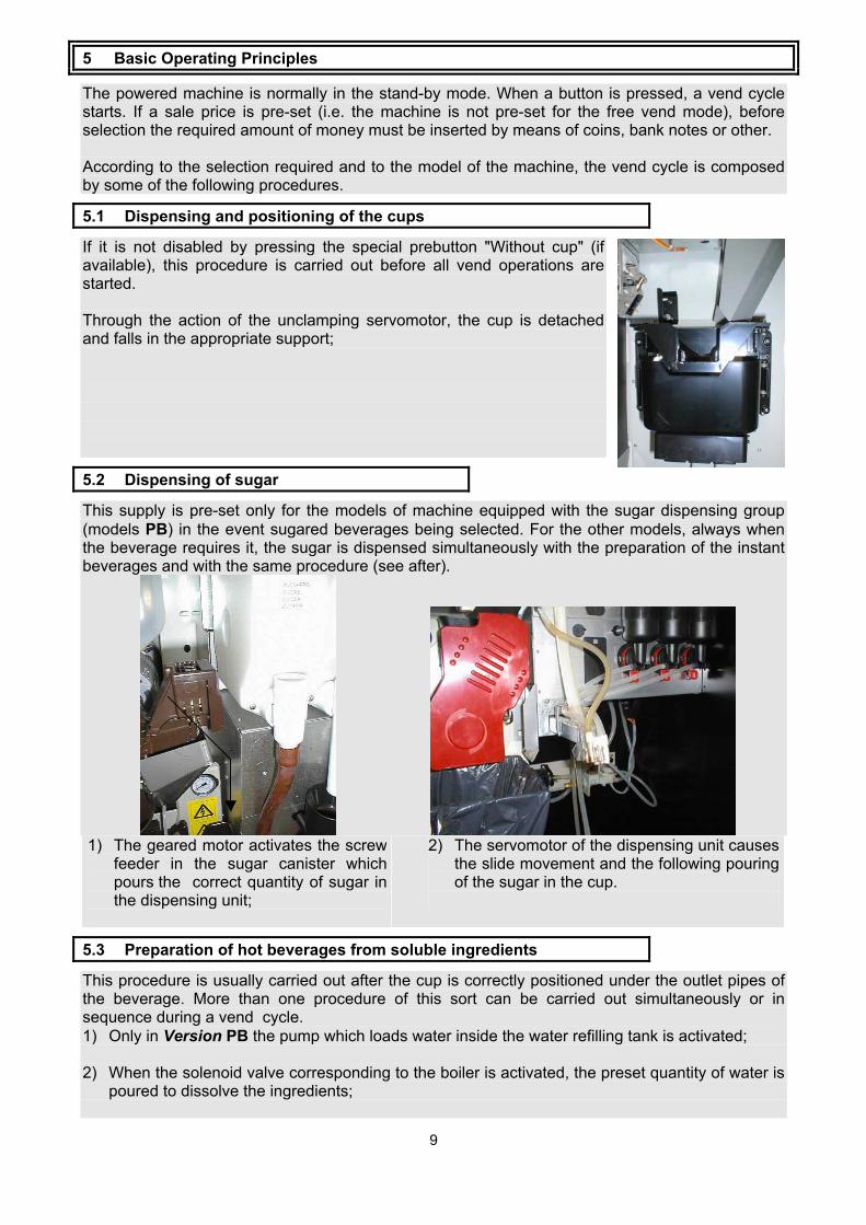
5.2 Dispensing of sugar
This supply is pre-set only for the models of machine equipped with the sugar dispensing group (models PB) in the event sugared beverages being selected. For the other models, always when the beverage requires it, the sugar is dispensed simultaneously with the preparation of the instant beverages and with the same procedure (see after).
1) The geared motor activates the screw
feeder in the sugar canister which pours the correct quantity of sugar in the dispensing unit;
2) The servomotor of the dispensing unit causes the slide movement and the following pouring of the sugar in the cup.
5.3 Preparation of hot beverages from soluble ingredients
This procedure is usually carried out after the cup is correctly positioned under the outlet pipes of the beverage. More than one procedure of this sort can be carried out simultaneously or in sequence during a vend cycle. 1) Only in Version PB the pump which loads water inside the water refilling tank is activated; 2) When the solenoid valve corresponding to the boiler is activated, the preset quantity of water is
poured to dissolve the ingredients;

10
3) If supplied, the mixer motor is activated; 4) The geared motor activates the screw feeder, in the canister of the corresponding ingredient,
which pours the correct quantity of ingredient in the mixing bowl. More than one canister of ingredients can be activated simultaneously for the same mixing bowl;
5) If present, the motor of the mixing bowl is switched off; 6) The solenoid valve correspondingl is switched off.
5.4 Preparation of the espresso coffee
This procedure is carried out only in the models equipped with the espresso coffee group (Version PBE) and after the cup is correctly positioned under the outlet pipes of the beverage. The execution priority between this procedure and the procedure for the preparation of hot beverages from instant ingredients is pre-set by the programme of the machine and varies according to the selection chosen. 1) The coffee grounds are ejected (this can occour also after 10 minutes of rest of the micro
coffee group) and the group moves to receive the coffee dose;
2) The electromagnet of the coffee throw dispensing unit is activated and the canister is open. The correct quantity of ground coffee flows by gravity in the brewer of the espresso coffee group; *
3) The coffee grinder is activated until the pre-set quantity in the throw dispensing unit is restored;
4) The coffee group moves to the infusion position: this occurs when the group movement motor is started. The lower filter is moved to close the brewer and press the preset throw the compress of ground coffee; *
5) The water coming from a water refilling tank, in which the water level is kept constant, is conveyed by pressure in the coffee boiler by means of a pump. After the activation of a solenoid valve, the same quantity of warmed up water is then conveyed to the coffee group.

11
6) The coffee group ends the cycle. * The operations marked with asterisk may be carried out in a different order according to the electronic presetting of the machine.
5.5 Preparation of filter coffee
This procedure is carried out only in the models equipped with a coffee brewing group (models FB), after the cup has been correctly positioned under the outlet pipes for the beverage vending. The execution priority between this procedure and the procedure for the preparation of hot beverages from instant ingredients is pre-set by the programme of the machine and varies according to the selection chosen.
1) The geared motor activates a screw feeder, which pours the pre-set quantity of ground coffee into the coffee group;
2) The coffee group moves to brewing position: this occurs when the group movement motor is started. The upper filter moves upwards to close the brewer and press the pre-set quantity of ground coffee;
3) The water coming from a water-refilling tank means of a pump. After the activation of a solenoid valve, the same quantity of warmed up water is then conveyed to the coffee group.
4) The coffee grounds are ejected and the group returns to rest position: this occurs when the group movement motor is started. The upper filter moves and opens the brewer. The coffee is ejected by the combined action of the lower filter and the ejection blade.
5.6 Dispensing of the stirrer
This procedure is carried out only in models equipped with stirrer feeder (Version PB), and it is carried out when the cup is correctly positioned under the outlet pipes for the beverage vending. The stirrer can be dispensed before or after the preparation of a beverage, according to the machine programme and selection made. Furthermore, a programmable function allows the user to pre-set selections for which the stirrer is to be dispensed.
1) The unclamping electromagnet detaches the stirrer from the stack in the feeder. The stirrer slides in the cup.
5.7 Preparation of cold instant beverages
This procedure is carried out only in the models of machine equipped with the refrigerating group for natural water (Version FP), usually when the cup is positioned under the outlet pipes for the beverage vending. 1) The water inlet solenoid valve is activated to load water inside the cold unit; 2) The corresponding solenoid valve in the refrigerating group is
activated and the correct quantity of water is poured into the mixing bowl to dissolve the ingredients;
3) If present, the mixing bowl is activated; 4) The geared motor activates the screw feeder of the canister of
the corresponding ingredient, which conveys the correct quantity of ingredient into the mixing bowl. More than one canister can be activated simultaneously for the same mixing bowl;
5) The solenoid valves are switched off; 6) If present, the mixing bowl motor is switched off.

12
6 Transportation
Only qualified personnel must move the machine. The machine must be carefully transported as any overturning of the machine is to be avoided. WARNING: The machine must be kept vertically positioned when moved to another location with the topside indicated on the box towards up. DO NOT OVERTURN THE MACHINE to avoid damages to the electronic boards. The machines are carried on pallet. WARNING: They must be moved on with dolly, at reduced speed and preventing any excessive bending movement of the machines. WARNING: the machine weighs from 100 to 110 Kg ca. Take care during transfer to avoid accidents to people (example: muscular rip, hernia, etc.). If the machine must be stocked for a period before installing it, please keep the machine in a dry place (the relative humidity must not exceed 80%), with temperature between 5°C and 30°C. Do not place on one machine more than another one. Do not overturn the machines.

13
7 Unpacking
The machine must be unpacked as follows:
1) Cut the protection film along one of the protection angle bar around the machine
2) Remove the pallet from the machine by lifting the two lateral hooks;
3) Take the key on the rear of the machine, near the power supply cord.
WARNING: the packing materials must be kept out of the reach of unauthorized people, specially children, as potentially hazardous. The disposal of special packing materials must be carried out by qualified waste recovery companies.
- Open the door and remove the adhesive tape from:
- the feeder cup cover - the drops tray - the weight of the stirrer
feeder (Version PB)
Remove the board prism positioned between the canisters of the ingredients and the top of the cabinet.
14
8 Positioning
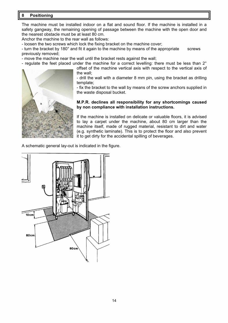
The machine must be installed indoor on a flat and sound floor. If the machine is installed in a safety gangway, the remaining opening of passage between the machine with the open door and the nearest obstacle must be at least 80 cm. Anchor the machine to the rear wall as follows: - loosen the two screws which lock the fixing bracket on the machine cover; - turn the bracket by 180° and fit it again to the machine by means of the appropriate screws previously removed; - move the machine near the wall until the bracket rests against the wall; - regulate the feet placed under the machine for a correct levelling: there must be less than 2°
offset of the machine vertical axis with respect to the vertical axis of the wall; - drill the wall with a diameter 8 mm pin, using the bracket as drilling template; - fix the bracket to the wall by means of the screw anchors supplied in the waste disposal bucket. M.P.R. declines all responsibility for any shortcomings caused by non compliance with installation instructions. If the machine is installed on delicate or valuable floors, it is advised to lay a carpet under the machine, about 80 cm larger than the machine itself, made of rugged material, resistant to dirt and water (e.g. synthetic laminate). This is to protect the floor and also prevent it to get dirty for the accidental spilling of beverages.
A schematic general lay-out is indicated in the figure.

15
9 Connection to the mains water supply and to the electrical supply
9.1 Connection to the mains water supply
Before proceeding to the connection carry out the following checks on the water to be used: - Make sure that the water supply is of drinking quality possibly through certificate of a laboratory; - Make sure that water mains pressure ranges from 0,1 MPa (1 bar) to 0,8 MPa (8 bar); - If the mains pressure is lower than 0,1 MPa (1 bar), a pump must be installed; - If the mains pressure is higher than 0,8 MPa (8 bar), a pressure reducer must be mounted, calibrated at 0,3 MPa (3 bar), on the water connecting hose of the machine; in any case the mounting of a pressure reducer is advisable in all installations where high pressure peaks occur. If not already existing, install a 3/8" gas tap to exclude the machine from the mains source in case of emergency. Connection of the tap to the machine must be made with a copper or plastic hose, which has been approved for food contact use and resistant to operating pressure not lower than 1 MPa (10 bar). Make sure that the water is free of impurities and does not feature excessive hardness (higher than 20 French Degrees). This shortcoming can be solved using normal water softeners. The SAGOMA machines, models PB and FB, are complete with a standard water-softening filter. The models SM can be provided with an optional filter. Lime scale can be notably reduced by the use of the filter, ensuring a longer life of all components in contact with water and reducing maintenance. Carry out the connection on the inlet coupling of the water softener or, should the filter not be mounted, directly on the inlet coupling of the water inlet solenoid valve. The water softener and the water inlet solenoid valve are both provided with a 3/8" gas male inlet coupling. If a water softening filter is mounted, the water hardness must be taken (special kits are available for sale) in order to define how often the filter shall be regenerated. This depends on the rate of use of the filter and on the grade of water hardness (see section "Regeneration of the water softener filter").
9.2 Connection to the electrical supply
Make sure that the grounding of the electrical mains to which the machine will be connected is in good conditions and in compliance with domestic and European standards concerning electrical safety. The machine is equipped with a power supply cord H50VV-F 3x1.5 mm2 with Shucko plug. WARNING: place the machine with the electrical plug easily accessible. Make sure that the electrical mains voltage is the same as indicated on the identification sticker of the machine and that the current rating of the plug is suitable for the current absorbed by the machine. The identification sticker is put inside the machine and can be seen opening the door. For connection, an electric plug, single-phase, 230V 50 Hz, for a maximum load of 15A is required. Any type of plug, which is incompatible with the socket of the machine, must be replaced. Do not use adaptors or multiple plugs.

16
10 How to activate or desactivate the machine
10.1 Safety switch
A safety switch is provided in the machine which cuts the power off all electrical and electronic components in the machine when the door is opened. If required, to switch the machine off open the door of the machine or unplug it from the electrical mains. Some operations will require to have the machine switched on and with the door open. To activate the machine with the door open, when specified in the instructions, insert the special plastic key, hanging on a cord near the switch and turn it clockwise by 90°. WARNING: the opening and switching on of the machine with the door open (unless for cleaning operations) must be carried out only by authorised, qualified personnel. Do not leave the machine open unguarded.
10.2 Diagnostics cycle of the switching up
When the safety key is inserted, the machine carries out a diagnostics cycle to check the position of the mobile components, the correct quantity of some ingredients and the correct water mains supply pressure. The display shows:
rheavendors 03-2002
date of the last upgrade of the software loaded in the vending machine
SAGOMA v 2.2 22 - 07 - 02
version of the master file loaded in the vending machine (i.e vers. 2.2)
vers. slave 1.m - - - - - - - - - - - - - - - - -
version of the slave file loaded in the vending machine (i.e vers. 1.m)
PLEASE WAIT - - - - - - - - - - - - - - - - - - - - - -
check coffee brewer
Only for versions PB
At the end of checks, the standard invitation message will appear on the display, e.g.:
rheavendors SAGOMA
TAKE A RELAX MOMENT

17
During the installation procedure, the following messages are displayed:
WATER REFILLING
meaning that some functions of the machine are temporarily inhibited for an easier and safe installation. In these phases, these messages replace the standard invitation message. In case of doubt, refer to installation instructions.

18
11 Start-up operations
11.1 Installation - Phase 1
The phase 1 of the installation of the vending machine contains the water loading of the boiler (Version H) or of the water refilling tank (Version PB) and the setting of the temperature of the boiler.
11.1.1 Loading the boiler of instant beverages This operation is carried out on all models of the machine. Place the liquid waste disposal bucket on the bottom of the machine, sliding it in the appropriate guide tracks, and insert the drain pipes, the pressure relief tube and the coffee brewer pipe (Version PB). Open the tap of the water circuit. Insert the key in the safety switch. After the switching on messages, the display shows:
WATER REFILLING
The machine starts automatically loading the boiler for instant beverages with water (Version SM); for espresso vending machines loads first the water refilling tank and then the boiler (Version PB). The boiler is filled up in about 3 min. The following message appears on the display:
rheavendors SAGOMA
TAKE A RELAX MOMENT
If the load is sufficient, by pressing the key PL inside the machine on the CPU protection, it is necessary to make some washings of the mixing bowls and of the coffee brewer (Version PB). The display shows:

19
WASHINGS 1 2 3 4
(Version H) Pressing buttons 1, 2, 3 and 4 the machine pours water from one of the beverage outlet spouts. Press the key PL inside the machine on the CPU protection to exit from WASHING mode. (Version E) Pressing button 1 many times the machine pours water from the outlet pipe of the coffee brewer. Pressing buttons 2, 3 and 4 the machine pours water from one of the beverage outlet spouts. Press the key PL inside the machine on the CPU protection to exit from WASHING mode.
11.1.2 Modification of the operating temperature Normally vending machines exit from factory with boiler’s temperature set at 10° C. To modify the temperature threshold, after loading water inside the boiler, insert the key in the safety switch and wait until the display shows
rheavendors SAGOMA
TAKE A RELAX MOMENT
Press the key PR inside the machine on the CPU protection, The display shows:
PROGRAMMING- - - - -BUTTON 1 - - - - - - - -
Press button 1 until the display shows:
PROGRAMMING - - - TEMPERATURE - - -
Pressing button 2 the display shows:
TEMPERATURE Boiler 10
Pressing button 4 and 5 set the correct value (the suggested values are 85°C for Instant machines and 92°C for Espresso machines).

20
Press button 1 to confirm the data and then key PROG inside the machine to exit from PROGRAMMING. Switch off and on the vending machine using the safety switch. The display shows:
WARMING PLEASE WAIT
Until the right temperature is reached inside the boiler. At the end of the operation the display will shows:
rheavendors SAGOMA
TAKE A RELAX MOMENT
11.2 Phase 2 of the installation
The phase 2 of the installation of the vending machine contains the cleaning of the parts in contact with foodstuff, the loading of the food products and the installation of some accessories.
11.2.1 Washing and disinfecting of components in contact with foodstuff.
With the vending machine switched on, make sure that the display shows:
rheavendors SAGOMA
TAKE A RELAX MOMENT
Proceed to clean in sequence all the mixing bowls, pressing the key PL inside the machine on the CPU protection and then buttons from 1 to 5 (depending on how many mixing bowls the machine has got). Use about 4 litres of water altogether. This will remove any possible trace of dirt from the boiler for instant ingredients. For models PB and FB only, carry out cleansing operations of the coffee group by means of a suitable cleaning product (refer to product instructions). - pour the cleaning product in the group through the coffee funnel. - carry out repeated washing cycles of the coffee group operating the key PL inside the machine on the CPU protection pressing button 1. Dispense about 1.5 litres of water. This will remove any trace of dirt inside the espresso boiler. Wash hands thoroughly. Prepare separately, in a suitable container, a disinfecting antibacterial solution of chlorine, according to the instructions enclosed in the chemical.

21
Remove all the ingredients canisters from the machine (including the canister for coffee in beans, if present) separate the main body from covers and slides and immerse all parts in the solution previously prepared.
Remove aspiration unit of the mixing bowl
Turn in the clock wise sense the red lever under the mixing bowl
Remove the mixing bowl itself, the bowl support
and the mixer's fan. Remove the silicone
beverage outlet tubes and pertaining supports. Immerse all parts in the solution.
Using a cloth soaked in the solution, proceed to clean also the attachment bases of the mixers, which remain fixed to the machine. The time of permanence in the solution, in order to obtain a full disinfecting, is stated on the packaging of the chemical.
22
At the end of the disinfecting, recover canisters and covers, dry them very carefully (using compressed air, a hair dryer or perfectly clean and sterile cloths) and reassemble them in the machine. Recover all other parts from the solution and put them back in the machine in opposite sequence with respect to disassembly. Carry out repeatedly washing cycles of the mixing bowls, pressing button WASHING under the cup feeder and then buttons form 2 to 4 (depending on how many the machine has got). Use about 2 litres of water altogether. This will remove all traces of disinfecting solution from the outlet pipes.
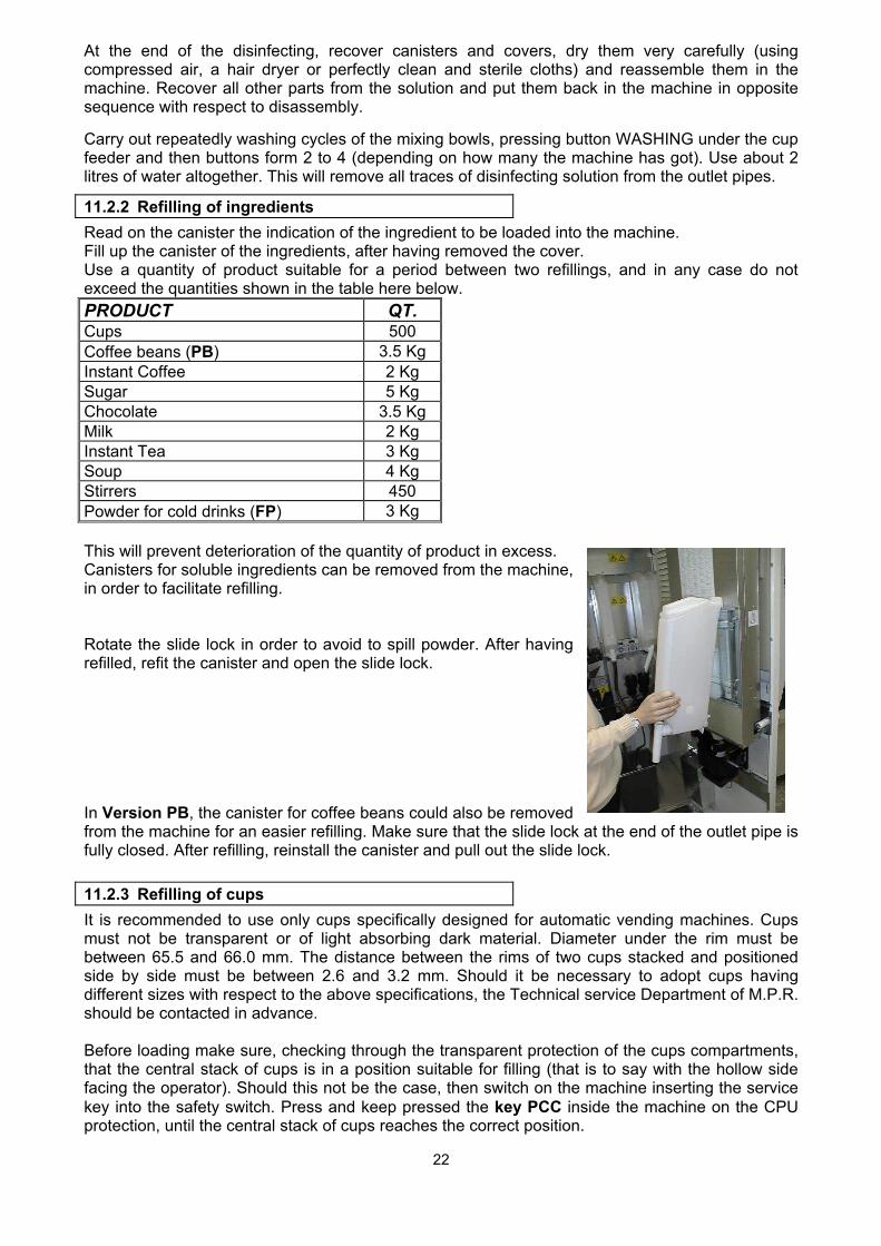
11.2.2 Refilling of ingredients Read on the canister the indication of the ingredient to be loaded into the machine. Fill up the canister of the ingredients, after having removed the cover. Use a quantity of product suitable for a period between two refillings, and in any case do not exceed the quantities shown in the table here below. PRODUCT QT. Cups 500 Coffee beans (PB) 3.5 Kg Instant Coffee 2 Kg Sugar 5 Kg Chocolate 3.5 Kg Milk 2 Kg Instant Tea 3 Kg Soup 4 Kg Stirrers 450 Powder for cold drinks (FP) 3 Kg This will prevent deterioration of the quantity of product in excess. Canisters for soluble ingredients can be removed from the machine, in order to facilitate refilling. Rotate the slide lock in order to avoid to spill powder. After having refilled, refit the canister and open the slide lock. In Version PB, the canister for coffee beans could also be removed from the machine for an easier refilling. Make sure that the slide lock at the end of the outlet pipe is fully closed. After refilling, reinstall the canister and pull out the slide lock.
11.2.3 Refilling of cups It is recommended to use only cups specifically designed for automatic vending machines. Cups must not be transparent or of light absorbing dark material. Diameter under the rim must be between 65.5 and 66.0 mm. The distance between the rims of two cups stacked and positioned side by side must be between 2.6 and 3.2 mm. Should it be necessary to adopt cups having different sizes with respect to the above specifications, the Technical service Department of M.P.R. should be contacted in advance. Before loading make sure, checking through the transparent protection of the cups compartments, that the central stack of cups is in a position suitable for filling (that is to say with the hollow side facing the operator). Should this not be the case, then switch on the machine inserting the service key into the safety switch. Press and keep pressed the key PCC inside the machine on the CPU protection, until the central stack of cups reaches the correct position.

23
Extract the safety switch. ATTENTION: carry out the loading of cups only when the machine is switched off. Do not attempt to manually rotate the central stack. Proceed to the loading as follows:
open the upper cover of the cup feeder;
pull the two mobile sides towards the outside, until they are blocked; slide the stacks of cups towards the inside of the machine, keeping them in vertical position.
The edge of the upper cup of each stack must reach a height between the limits indicated on the sticker of instructions placed inside the cup feeder. This allows a regular operation of the inside mechanisms of the cup feeder itself;
close the cup feeder with the upper cover.
11.2.4 Refilling of stirrers The stirrers feeder is standard fit on the models PB, as an optional in models SM. It is recommended to use only stirrers suited to automatic vending machines. The thickness of the stirrers must range between 1.2 and 1.8 mm and their length must be approx. 89 mm. If stirrers with different dimensions from those specified must be used, please contact the technical service of M.P.R.
When the machine is open and off, lift
and rotate the cup feeder. Remove the metal weight.

24
Slide along the guide track the stirrers still hold together with the packing band and, once they have reached the end of the guide, rip the band off.
Insert the weight again. Refit the cup feeder.
11.2.5 Inserting the selection labels The selection labels are supplied in the special pocket in the Manual. When the machine if open and off, release and turn the cup feeder. Loosen the screws to remove the protection of the area for the slipping of labels. Slip the labels in the special slots following the diagram on the Memory Configuration Chart attached to the Manual. Check their correct position from outside the machine. Lift and refit the cup feeder.
11.2.6 Application of the collection bag for coffee grounds
In models PB and FB, 5 bags are supplied together with the machine to be used for the collection of the coffee grounds They are in the liquid waste disposal bucket. Pull the support of the bag out from underneath the espresso group. Slide the bag around the support and replace the support and bag back to the original position.

25
12 Programming of the machine
12.1 Memory
The machine is controlled by a programme stored in the microprocessor of the FLASH memory, installed on the CPU board. The program stored in the memory can be updated with a FLASH serial card or with a serial cable. At the switching on of the machine a mssage will display the latest version iof the software loaded into the machine.
12.2 Factory set parameters
The machine is supplied already pre-set for the most common operation parameters. In particular: - configuration of the version; - throw of coffee, powdered ingredients, tea and quantity of water required; - vend prices (set to 0: the machine is in the free vend mode); - pre-setting for the use of the system of parallel payment; - the clock function disabled; The Data set of the machine must be modified only if the pre-set factory parameters are not complying with the required use. The parameters stored into the memory (configuration file) can be updated with Rhea black flash card programmed with the Rheaction Program.
• Download the configuration data file furnished from the factory on the flash card using the Rheaction Program;
• Switch off the machine; • Insert the flash card into the flash slot in the front of the machine. • Switch on the machine. • Wait until the display shows:
1 = KEY - - - > VMC 2 = VMC - - - > KEY
• Press button 1. The display shows:
Programming EAROM data
Programming OK
• Switch off the machine. • Extract the flash card.
12.3 How to enter and exit from the programming mode
To modify the operation parameters of the machine it is necessary to enter in the programming mode.
26
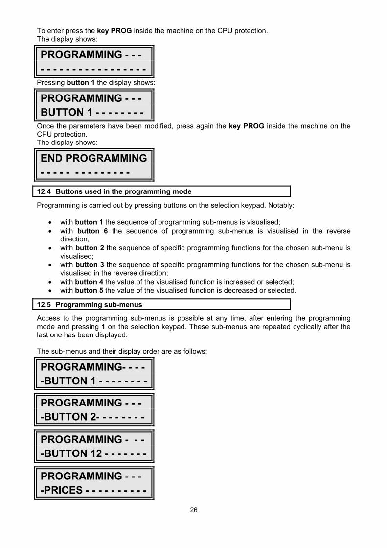
To enter press the key PROG inside the machine on the CPU protection. The display shows:
PROGRAMMING - - - - - - - - - - - - - - - - - - - -
Pressing button 1 the display shows:
PROGRAMMING - - - BUTTON 1 - - - - - - - -
Once the parameters have been modified, press again the key PROG inside the machine on the CPU protection. The display shows:
END PROGRAMMING - - - - - - - - - - - - - -
12.4 Buttons used in the programming mode
Programming is carried out by pressing buttons on the selection keypad. Notably:
• with button 1 the sequence of programming sub-menus is visualised; • with button 6 the sequence of programming sub-menus is visualised in the reverse
direction; • with button 2 the sequence of specific programming functions for the chosen sub-menu is
visualised; • with button 3 the sequence of specific programming functions for the chosen sub-menu is
visualised in the reverse direction; • with button 4 the value of the visualised function is increased or selected; • with button 5 the value of the visualised function is decreased or selected.
12.5 Programming sub-menus
Access to the programming sub-menus is possible at any time, after entering the programming mode and pressing 1 on the selection keypad. These sub-menus are repeated cyclically after the last one has been displayed. The sub-menus and their display order are as follows:
PROGRAMMING- - - - -BUTTON 1 - - - - - - - -
PROGRAMMING - - - -BUTTON 2- - - - - - - -
PROGRAMMING - - - -BUTTON 12 - - - - - - -
PROGRAMMING - - - -PRICES - - - - - - - - - -
FREE

27
PROGRAMMING - - - -COINS - - - - - - - - - - -
PROGRAMMING - - - -TEMPERATURE - - -
PROGRAMMING - - - -MISCELLANEOUS - -
DIAGNOSTICS - - - - - - - - - - - - - - - - - - - - - -
SALES AUDIT - - - - - - - - - - - - - - - - - - - - -
PROGRAMMING- - - - -MDB- - - - - - - - - - - -
PROGRAMMING- - - - -CLOCK- - - - - - - - - -
REGISTRATION OUT OF ORDERS
PROGRAMMING - - - EVA-DTS - - - - - - - - -
12.5.1 Pre-setting of buttons The modification of throws is a delicate operation as the good operation of the machine can be affected. As a general rule, it is recommended to keep in mind that when instant ingredients are dissolved in water, a brief interval to rinse the mixing bowl must be foreseen at the end of the powdered ingredient vending. This is provided by programming a dispensing time for water about 2 sec. longer than the dispensing time for the instant ingredients. To each of the 12 buttons it is possible to associate the recipe of any drinks. To proceed at the pre-setting of each button, in the programming mode, press 1 until the display shows:
PROGRAMMING- - - - -BUTTON 1- - - - - - - -
Press 2 to visualise one of the following functions:
FUNCTIONING

28
INHIBITED
PRE SELECTION
Only for FP versions the display shows also the function:
FUNCTIONING COLD
Scroll the functions pressing 4 and 5. To inhibit button, which is going to be programmed, confirm INHIBITED pressing 1. Setting of a selection To associate a selection to button which is going to be programmed, confirm FUNCTIONING. For the FP versions it is possible prgramme cold drinks selecting the function FUNCTIONING COLD. Press button 2. The display shows one of the following options:
PROGRAMMING: COMPLETE
PROGRAMMING: REDUCED
Use 4 and 5 to visualise the options. Choose PROGRAMMING COMPLETE if you want the possibility to programme all the parameters of each product, otherwise choose PROGRAMMING REDUCED. Pressing 2 (Version PB), the display shows:
COFFEE WATER 0=inhib. cc:
This parameter is present only in machines with the coffee brewer. Use this parameter to adjust the coffee beans water quantity. Activate this parameter only if you want to associate to this button a drink made with coffee beans. Increase or decrease the value pressing respectively 4 and 5. To inhibit this function programme the value 0.0. Press again 2 (Version PB). The display shows:
opt. coffee-milk (0-1) X
Use this parameter to set the priority of starting between milk and ground coffee for drinks made with these ingredients. Increase or decrease the value pressing respectively 4 and 5. Set this parameter at 0 if you want that milk starts before ground coffee and the value 1 for the opposite.
Pressing in sequence 2 the display shows:
PRODUCT X 0=inhib. .0
The number of the product shows the position of the canister inside of the machine starting to count from the left the possible positions of the product motors.

29
If the PRODUCT X is necessary for the drink that is being set, increase or decrease until the desired value, pushing respectively 4 and 5; otherwise inhibit the ingredient setting its value to 0.0. Pressing again 2 the display shows:
start delay PRODUCT X .0
Pressing respectively 4 and 5 increase or decrease the ingredient’s pouring delay after the beginning of the selection. Pressing again 2 the display shows the same items for other products, that can be set as the previous one following the recipe of the desired drink. Pressing again 2 the display shows:
WATER X time 0=inhib. .0
The number of the WATER shows the position of the mixer starting from the left. Increase or decrease the value pressing respectively 4 and 5; otherwise inhibit WATER setting its value to 0.0. Pressing again 2 the display shows:
start delay WATER 1 .0
Pressing 4 and 5 increase or decrease respectively the water pouring delay after the beginning of the selection. Pressing again 2 the display shows:
flow WATER X slow
Pressing 4 and 5 it is possible to choose among the three parameters “slow”, “medium”, “quick” to increase or decrease the correspondent water flow. Pressing again 2 the display shows:
MIXER X 0=inhib. .0
Increase or decrease the value of the time of working of the mixer pressing respectively 4 and 5; otherwise inhibit the MIXER setting its value to 0.0. Pressing again 2 the display shows:
Start delay MIXER X 1.0
Pressing 4 and 5 increase or decrease respectively the mixer start delay after the beginning of the selection. Pressing again 2 the display shows:
speed MIXER X 0
Pressing 4 and 5 increase or decrease respectively the mixer speed of the selection (0 = maximum speed, 5 = minimum speed). Pressing again 2 the display shows the same items for other mixers, that can be set as the previous one following the recipe of the desired drink. Pressing again 2 the display shows:
selection name: standard
Pressing button 4 and 5 it is possible to modify the message shown in the display during the preparation of the drink. If you select the value standard, the display will show:

30
drink number N preparing
otherwise if you select one of the available selection names the display will show:
selection name preparing
Press 1 to programme the following button. ATTENTION: if all the parameters of a button set as FUNCTIONING are programmed at 0, the vending machine will dispense ONLY CUP.
Setting of a pre-selection To associate a preselection to the current button, choose PRESELECTION pressing 4 and 5. Pressing again 2 the display shows:
presel. message DECAFFEINATED
Pressing 4 and 5 the display shows all the other available pre-selections:
presel. message BARLEY
presel. message NO CUP
presel. message EXTRA MILK
presel. message SHORT
Only for the models not equipped with buttons for sugar adjusting with leds, there are also the following pre-selections:
presel. message NO SUGAR
presel. message EXTRA SUGAR
DECAFFEINATED/BARLEY To associate to the current button the preselection DECAFFEINATED/BARLEY, choose it in the menu and press 2. The display shows:
canister DEC./BARLEY nr: 0

31
Press 4 and 5 to increase or decrease the position of the canister in which decaffeinated/barley coffee is present. Pressing again 2 the display shows:
ev-mixer DEC./BARLEY nr: 1
Press 4 and 5 to increase or decrease the position of the solenoid valve to associate to decaffeinated canister. Pressing again 2 the display shows:
price decaf/barley 0 = + 1 = -
Pressing 4 and 5, set 0 for a price increasing or 1 for a price decreasing; the price will be modified of the value of the price associated at the current button. Pressing again 2 the display shows:
enab. presel. For button1 YES
Choose buttons to which associate the preselection that is going to be programmed. Press 2 and 3 to visualise all buttons and choose YES or NO with 4 and 5 to set or to inhibit the preselection at button shown on the display. ATTENTION: in version PB during the setting of the drinks with coffee beans, you have to programme also the parameters of the drink with decaffeinated/barely coffee (PRODUCT, MIXER, EV); in version SM during the the programming of the drinks with instant coffee, set the parameters of both coffees; the two instant coffee canisters must have the same mixing bowl. NO CUP To associate to the current button to the preselection NO CUP, choose it in the menu and press 2. The display shows:
enab. presel. for button 1 YES
Proceed as for previous preselections. EXTRA MILK To associate to the current button the preselection EXTRA MILK choose it in the menu and press 2. The display shows:
canister MILK nr: 0
Pressing 4 and 5 to increase or decrease the number of the product motor corrispondent to the canister in which milk is present. Pressing again 2 the display shows:
quantity EXTRA MILK + .0
Pressing 4 and 5 set the extra quantity milk wanted. The display shows:
enab. presel. for button 1 YES
Proceed as for previous preselections.

32
SHORT To associate to the current button the preselection SHORT choose it in the menu and press 2. The display shows:
presel. message SHORT
Pressing again 2 the display shows:
WATER quantity SHORT - .0
Pressing 4 and 5 set the percentage (%) of water quantity to decrease from normal water quantity for short drinks. Pressing again button 2 the display shows:
enab. presel. for button 1 YES
Proceed as for previous preselections. NO SUGAR To associate to the current button the preselection NO SUGAR choose it in the menu and press 2. The display shows:
canister SUGAR nr: 0
Pressing 4 and 5 to increase or decrease the number of the product motor corrispondent to the canister in which sugar is present. Pressing again button 2 the display shows:
enab. presel. for button 1 YES
Proceeed as for previous preselections.
EXTRA SUGAR To associate to the current button the preselection EXTRA SUGAR choose it in the menu and press 2. The display shows:
canister SUGAR nr: 0
Pressing 4 and 5 to increase or decrease the number of the product motor corrispondent to the canister in which sugar is present. Pressing again 2 the display shows:
quantity EXTRA SUGAR + .0
Pressing 4 and 5 set the extra quantity sugar wanted. The display shows:
enab. presel. for button 1 YES
Proceed as for previous preselections. At the end of the setting of buttons, push 1 to confirm the set data.

33
12.5.2 Pre-setting of the normal sale prices One price for each selection available can be memorised in the machine. When a selection is matched to a price set to zero, the selection is in the free vend mode. To modify sale prices, in the programming mode, press button 1 until the sub-menu
PROGRAMMING - - - PRICES - - - - - - - - - -
is visualised. Press buttons 2 and 3 and select the price to be modified. For example:
PRICE X XXXX
will appear on the display. Press 4 and 5 to modify the value of the price displayed. Press 1 to confirm the set data. When the invitation message is visualised and with machine open and switched on, the pre-set sale prices can be by-passed by entering the selection test mode (free-vend). To have access to this mode, press key "FREE" inside the machine on the CPU protection. The display shows:
FREE VEND
At this point the machine is able to dispense any selection, without charge. Selection vended in the selection test mode are counted in a separate counter (see "Reading of sales data"). To exit from the selection test mode, press the key FREE inside the machine on the CPU protection again.
12.5.3 Presetting of coin-set The set of values that the machine assigns to each signal (canal) received from the payment system is called coin-set. Press 1 until to visualize the sub-menu:
PROGRAMMING- - - - -COINS- - - - - - - - - - -
Pressing 2 the display shows from:
COIN A 0
to:
COIN F 0
Pressing 4 and 5 change the value of the visualised coin.

34
Press 1, exit from the programming mode, and switch the machine off and on. The machine will use the new coin-set. For further information see the paragraph “ Modifying other operation parameters (Miscellaneous)” the parameter “single or multi vend”.
12.5.4 Modification of the operating temperature The machine defines and regulates water temperature in the boilers. To modify the temperature thresholds, in the programming mode, press 1 until the sub-menu
PROGRAMMING TEMPERATURE
is displayed. Pressing 2 the display shows:
TEMPERATURE Instant Boiler X
Pressing 4 and 5 set the value. Pressing 2 (Version PB) the display shows:
TEMPERATURE Espresso XXX
Pressing 4 and 5 set the value. Pressing 2 (Version PB) the display shows:
DEF. FIRST COFFEE N
Use this parameter to obtain drinks made with coffee beans at a right temperature also after long periods of inactivity of the coffee brewer. When this parameter is set (it is indicated in minutes) if for N consecutive minutes the machine does not make any selection with coffee beans, before making the next selection with coffee beans the machine will wait that the temperature inside the boiler will reach the value set at the parameter “TEMPERATURE first coffee”. Press 4 and 5 to increase and decrease the value. Pressing 2 (Version PB) the display shows:
TEMP. FIRST COF. MM
Use this parameter to obtain drinks made with coffee beans at a right temperature also after long periods of inactivity of the coffee group. This value indicates the temperature that the water inside the boiler should reach before making a drink made with coffee beans if for a time (in minutes) equal or superior to the one set at the parameter DEF. FIRST COFFEE the machine has not made any drinks made with ground coffee. To disable this function, set the parameter DEF. FIRST COFFEE at a value equal or lower than the one set at the parameter COFFEE T. Press 4 and 5 to increase and decrease the value.
At the end of programming, press 1 to confirm the set data.
12.5.5 Modifying other operation parameters (miscellaneous)
To modify parameters, in the programming mode, press 1 until the sub-menu
PROGRAMMING MISCELLANEOUS
is visualised.
Pressing 2, the display shows:

35
MACHINE CODE A 0
Pressing again 2, the display shows:
MACHINE CODE B 0
Press 4 and 5 to associate to each vending machine personal codes. These numbers are useful only when a data audit system is used with the machines.
Pressing again 2, the display shows:
MESSAGE NUMBER 0
Press 4 and 5 the number of the stand by message to show on the display during the working of the machine (from 0 to 7). Set the message number 3 only if a programmable message is been set with the rheaction programme with the PC.
Pressing again 2, the display shows one of the following options (scroll the options pressing 4 and 5):
type coin-mech PAR. SING. VEND.
type coin-mech PAR. MULT. VEND.
type coin-mech EXECUTIVE
type coin-mech EXEC. PRICE HOLD.
type coin-mech MDB
Select:
type coin-mech PAR. SING. VEND.
to programme a parallel payment system in single vend;
type coin-mech PAR. MULT. VEND.
to programme a parallel payment system in multi vend;
type coin-mech EXECUTIVE
to programme an Executive serial payment system;

36
type coin-mech EXEC. PRICE HOLD.
to programme an Executive serial payment system working in PRICE HOLDING;
type coin-mech MDB
to programme an MDB serial payment system.
Pressing again 2, the display shows:
fan delay sec. 15
pressing 4 and 5 it is possible to modify the value of the time range between the end of the cycle of a drink and the switching off of the aspiration fan. Pressing again 2, the display shows:
time beep 0.3
Pressing 4 and 5 it is possible to modify the value correspondent to the beep signal that indicates the end of the distribution of the drink. Pressing again 2, the display shows:
decimal numbers: 0
Pressing 4 and 5 it is possible to set the number of the decimal digits after comma according with the values of the coins, which the machine has to accept (Es: 0=50, 1=5,0 2=0,50…). Pressing 2, the display shows:
language english
Pressing 4 and 5 it is possible to select one of the 3 available languages. Pressing again 2, the display shows (Version PB):
type GRINDER 0=after 1=before X
This parameter fixes if the grinder should be activated at the beginning or at the end of the cycle. Programme this value at 0 to make the grinding at he end of the cycle and at 1 to make it at the beginning. Pressing again 2, the display shows:
STIRRER SUGAR
Pressing 4 and 5 it is possible to choose among the following possibilities:
• SUGAR: the stirrer is dispensed only with the drinks where sugar is added • NO SUGAR: the stirrer is dispensed with the drinks where sugar is added also when is
pressed the pre-selection NO SUGAR • ALL: the stirrer is dispensed with all the drinks
Programme this value at 1 to enable the connection. At the end of the programming, press 1 to confirm the set data.

37
12.5.6 Diagnostics programmes In the programming mode, a certain number of diagnostics programmes can be carried out in order to test the correct operation of some components of the machine. To modify the parameters, in the programming mode, press 1 until the sub-menu
DIAGNOSTICS - - - - - - - - - - - - - - - - - - - - - -
is visualised. Pressing again 2, the display shows:
ABIL. DISPLAY TEMP. 1=YES 0
is displayed. According to the value of the parameter, which can be modified with 4 and 5, the inside temperature of the machine is displayed in real time. Set the parameter to 1 (it is normally 0) to have the display of temperature. To read the temperature, press 1 and exit from the programming mode. Pressing again 2, the display shows:
CUP TEST SEL. 4
Press 4 to dispense a cup. Pressing again 2, the display shows:
STIRRER TEST SEL. 4
Press 4 to dispense a stirrer. Pressing again 2, the display shows:
SUGAR TEST SEL. 4
Press button 4 to verify the correct sugar dispensing. Pressing again 2, the display shows:
TENSION XX.X
This parameter visualises the value of the supply tension at the 24 V actuators. This value should be included between 24 V and 28 V. At the end of programming, press 1 to confirm the set data.
12.5.7 Reading of the sales data The last sub-menu which can be selected in the programming mode concerns the reading of the sales data. The machine keeps various counters stored, which allow a direct reading for consumption and cashing. To have an immediate reading of the total number of cycles carried out, simply keep pressed the key FREE the machine with the machine switched on and with the invitation message visualised. The following message will be displayed:
T CYCLES XXXXXX
All counters, except that of total cycles, can be set to zero. To reset a counter, when it is visualised on the display, press 4. Read the parameter, in the programming mode, by pressing 1 until the sub-menu
SALES DATA - - - - - - - - - - - - - - - - - - - - - - -
38
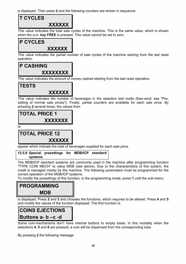
is displayed. Then press 2 and the following counters are shown in sequence:
T CYCLES XXXXXX
This value indicates the total sale cycles of the machine. This is the same value, which is shown when the a.m. key FREE is pressed. This value cannot be set to zero.
P CYCLES XXXXXX
This value indicates the partial number of sale cycles of the machine starting from the last reset operation.
P CASHING XXXXXXXX
This value indicates the amount of money cashed starting from the last reset operation.
TESTS XXXXXX
This value indicates the number of beverages in the selection test mode (free-vend: see "Pre-setting of normal sale prices"). Finally, partial counters are available for each sale price. By pressing 2 several times, the values from
TOTAL PRICE 1 XXXXXXX
to
TOTAL PRICE 12 XXXXXX
appear which indicate the total of beverages supplied for each sale price.
12.5.8 Special presettings for MDB/ICP standard systems
The MDB/ICP standard systems are commonly used in the machine after programming function "TYPE COIN MECH" to value MDB (see above). Due to the characteristics of this system, the credit is managed mostly by the machine. The following parameters must be programmed for the correct operation of the MDB/ICP systems. To modify the presettings of this function, in the programming mode, press 1 until the sub-menu:
PROGRAMMING MDB
is displayed. Press 2 and 3 and chooses the functions, which requires to be altered. Press 4 and 5 and modify the values of the function displayed. The first function is:
COINS EJECTIONS Buttons a- b –c -d
Some coin-mechanisms don’t have internal buttons to empty tubes. In this modality when the selections 4, 5 and 6 are pressed, a coin will be dispensed from the corresponding tube. By pressing 2 the following message

39
FORCED VEND X
is displayed. Press 4 and 5 and modify the values of the function displayed. If this value is programmed at 0 it is possible to insert money and then press button of the return change without making any selection; if this value is programmed at 1 a selection must absolutely be pressed after that the money has been put inside the machine (this to prevent that the Vending Machine could be used like a change money machine). By pressing 2 the following message
CREDIT MAX XXXXX
is displayed. Press 4 and 5 and modify the values of the function displayed. This parameter indicates the maximum value of credit accepted by the machine. When the maximum credit limit is overcome, the machine will accept no other payment. Leave this parameter set to 0 if no limitation is required. By pressing 2 the following message
MAX REST XXXXX
is displayed. Press 4 and 5 and modify the values of the function displayed. This parameter indicates the maximum value of change dispensed by the token machine (only with system for change). Leave this parameter set to 0 if no limitation is required. By pressing 2 the following message
VEND. SING-MULT X
is displayed. Press 4 and 5 and modify the values of the function displayed. Another characteristic of the MDB/ICP machine with system for change is the multisale function. This means that, instead of giving back the correct change and end vend cycle, as usually provided for, the machine keeps the possible residual credit available for the next selection. In order to have the change back, the customer must press button for coin ejection. This function is available when this parameter is set at 1. ATTENTION: for mixed MDB/ICP systems, with system for change or card reader or credit key, it is advisable to activate the multisale mode. Transfer of credit to card or key (if present) will be carried out only when button for the coin ejection is pressed. By pressing button 2 the following message
TOKEN VALUE X
is displayed. Press 4 and 5 and modify the value of the token. By pressing 2 the following message from
COIN A 0=ACC X
to:
COIN P 0=ACC X
is displayed.

40
Press 4 and 5 and modify the values of the function displayed. Set at 0 each coin from A to P which the coin-mechanism must accept and at 1 all the coins which the machine must not accept. This set of parameters is working only when the tubes of the coin-mechanism have inside enough coins to give back change. Pressing again 2 the display will show the set of the parameters that will be active when the tubes of the coin-mechanism don’t have enough coins inside to give back change. From:
COIN A NO-RE X
until:
COIN P NO-RE X
Press 4 and 5 and modify the values of the function displayed. Set at 0 each coin from A to P which the coin-mechanism must accept and at 1 all the coins, which the machine must not accept.
By pressing 2 the following messages:
TUBES VALUE XXXXXXXX
is displayed.
This value means the total of money inside the tubes of the coin-mechanism. At the end of programming, press 1.
12.5.9 Pre-setting of functions based on the internal clock
The machine is equipped with an internal clock able to up-date the time also when the machine is switched off. Some functions of the machine are based on the internal clock: to modify the presettings of the clock, in the programming mode, push 1 until the sub-menu
PROGRAMMING - - - CLOCK - - - - - - - - - -
is displayed.
Press 2 and 3 and choose the function, which requires to be altered. Press 4 and 5 and modify the value of the displayed function. The first two functions are:
SWITCHING ON XX.XX
SWITCHING OFF XX.XX
The time when the machine should be switched on and off (hh.mm) can be programmed. When the machine is off, only the option to accept coins and selections is disabled. Furthermore, as a measure to save energy, when the machine is off the water temperature in the boilers is decreased to 70°. When one of the two values is set to 00.00, the machine is never switched off.
Pressing 2 the following message
CLEANING XX.XX

41
appears.
This function programmes the time for the daily automatic cleaning cycle. It is advisable to programme an automatic cleaning at the beginning of the day. The automatic cleaning is completed with the injection a quantity of water equal to about 100 ml in the coffee group (if present) and in all the mixing bowls. In the versions PB the automatic cleaning cycle of the coffee group can be followed by the vending of 1 or 2 coffees in order to have the correct taste of coffee immediately with the first sale after the cleaning cycle. For further information on how to programme this option at the paragraph “Modifying other operation parameters (Miscellaneous)”. By pressing 2 the following messages
HOUR: hh.mm
DAY: dd
MONTH:
mm
YEAR: yy
will appear. These functions are foreseen to adjust the current time (hh.mm), the current month (mm) and day (dd) and the current year (yy), respectively. At the end of programming, press 1.
12.6 Storing of OUT OF ORDERS
The machine stores the last 20 OUT OF ORDERS. To read them on the display, press 1 until the display shows:
STORING OUT OF ORDERS
Pressing 2, the display shows hour, day, month and year of the last 20 OUT OF ORDERS.
n. 1 OFF NNN hh:mm gg - mm - aa
To delete, visualize each OUT OF ORDER and keep pressed 4 for some seconds.
12.7 EVA-DTS
The machine with proper hardware may be programmed to collect data following EVA-DTS protocol. To proceed at the programming of these parameters, press 1 until the display shows:
PROGRAMMING EVA-DTS
Pressing 2, the display shows:
Code ID 101 00

42
which identifies the number of the machine. Pressing 2, the display shows:
Code ID 102 00
which identifies the model of the machine. Pressing 2, the display shows:
Code ID 104 00
which identifies the location of the machine. Pressing 2, the display shows:
Address VIDTS 00
which identifies which peripherics should be contacted during data collection.

43
13 Installation of the payment systems
To install the payment systems always follow the instructions supplied by the manufacturer. For information only, the installation of a token machine is hereunder described.
Remove the CPU and the coin-mech protections.
Fit the token machine. Connect the dialogue cable to the CPU board.
In the case of Executive standard systems, the cable is supplied by the machine; in the case of other systems, the cable is supplied by the payment system. Only for Executive standard systems: connect the power supply cord to the 24V connector placed in the fitting area of the token machine. Switch the machine on by inserting the key in the safety switch. Enter the programming mode (see section "Entry and exit from the programming mode). Pre-set the specific parameters for the token machine which has just been installed (see section "Pre-setting of payment systems" and following). Exit from the programming mode. The machine is now ready to use the coin-mechanism.

44
14 Cleaning and loading operations
To guarantee a correct operation of the machine, it is advisable to carry out the periodic cleaning operations hereunder described. Some of these operations are required to comply with health legislation in force. The cleaning operations must not be carried out when the machine is not working (e.g. if it has already been temporarily out of service following instructions given in section "Out of service - Temporary"). The cleaning operations must be carried out when the machine is open and switched off. The loading of ingredients, if required, must be carried out after any cleaning operation.
14.1 Daily cleaning
The objective of these operations is to avert any growth of bacteria in areas in contact with foodstuff. Before any operation, wash your hands thoroughly. To carry out these operations use two clean cloths as well as a clean brush (only for models PB with traditional group); if drinkable water near the machine is not available, also provide for a container with drinkable water. Proceed as follows: Make sure that the machine is off.
1) With a damp cloth, clean the visible components in the ingredients vend area.
2) Carefully remove and rinse: - the aspiration unit of the mixers;
- the mixing bowls, the mixer supports
and fans; - the silicone, outlet
tubes of the ingredients; - the slides of the ingredients and the relative caps;
- the area where the cup rests (cup station).
When the mixers are disassembled, clean the basis of the mixer supports with a damp cloth. Dry the components thoroughly with a dry cloth and mount again all the washed components to the original position.

45
For machines equipped with coffee brewer (Versions PB), remove the coffee brewer, wash it with drinkable water (better if with running water) and refit it. This operation is carried out as follows:
- remove the red cover of the coffee brewer;
- remove the coffee grounds conveyer;
- take out the coffee outlet pipe;
- take out the coffee brewer inlet coffee pipe
-unhook the coffee brewer turning the pivot
- take out the coffee brewer.
- reassemble the coffee group in the original position. Empty, clean or replace the containers of liquid waste disposal and coffee grounds (Versions PB and FB).
14.2 Weekly cleaning
These operations are carried out once a week, after completing the daily cleaning operations. Make sure that the machine is off. With a damp cloth clean the surface where the ingredient canisters lay and the bottom of the machine to remove any powder eventually spilled during loading. Clean the outside of the machine, taking care to the vend area.
14.3 Refilling of consumption products
When required, proceed to the following loading operations. ATTENTION: the loading operation of ingredients must be carried out only with machine off.
14.4 Refilling of cups
The cups used for loading must be approved by technical personnel who is in charge of the maintenance of the machine. Load the cups as follows:

46
- open the upper cover of the cup feeder;
- pull the two mobile sides towards the outside, until they are blocked;
- slide the stacks of cups towards the inside of the machine, keeping them in vertical position. The edge of the upper cup of each stack must reach a height between the limits indicated on the sticker of instructions placed inside the cup feeder. This allows a regular operation of the inside mechanisms of the cup feeder itself
- close the cup feeder with the upper cover. 14.5 Refilling of stirrers The stirrers used for loading must be approved by technical personnel who is in charge of the maintenance of the machine. Load the stirrers as follows.
When the machine is open and off, release
And rotate the cup feeder. Remove the metal weight.

47
Slide the stirrers still hold together with the packing band along the guide track and, once they have reached the end of the guide, rip the band off.
Insert the weight again. Refit the cup feeder.
14.6 Refilling of ingredients Read the indication of the ingredient to load on the canister. Fill in the canisters after removing the cover. Use a quantity of product suitable for a period between two refillings, and in any case do not exceed the quantities shown in the table here below.
14.6.1.1 PRODUCT QT. Cups 500 Coffee beans (PB) 3.5 Kg Instant Coffee 2 Kg Sugar 5 Kg Chocolate 3.5 Kg Milk 2 Kg Instant Tea 5 Kg Soup 4 Kg Stirrers 550 Powder for cold drinks (FP) 3 Kg This will prevent deterioration of the quantity of product in excess.
The canisters for instant ingredients can be removed from the machine for an easier loading. Turn the closure of the slide in order to prevent spilling of powder.
After loading, refit the canister and reopen the closure of the slide.
In the versions PB, the canister of coffee in beans can be removed for an easier loading.

48
Make sure that the closing tongue of the exit funnel is pushed right in.
After loading, reassemble the canister and pull the tongue out.

49
15 Ordinary and prevention maintenance
15.1 Monthly maintenance
15.1.1 Disinfecting of components in contact with ingredients
These operations must be carried out once a month to ensure the hygiene of the machine. These operations have already been described in the paragraph "Cleaning and Disinfecting of components in contact with ingredients".
15.1.2 Adjustment of the solenoid valves of instant ingredients
The presence of lime scale can affect the correct operation of the solenoid valves of the instant ingredients. During vending, check that the water flow from each solenoid valve is more than sufficient to completely rinse the corresponding mixing bowl at the end of one selection. If the flow is limited, turn the adjustment screw of the solenoid valve.
15.1.3 Adjustment of grinding This section is for Versions PB only. The brewing time for a 50 ml espresso coffee must be around 20 sec. If, due to the wear and tear of the grinder, the brewing time is shorter, turn the adjustment ring nut of the grinder by 1-3 steps in the direction indicated by the sticker near the grinder itself. A thinner grinding and therefore, an adequate brewing time is then obtained.
15.1.4 Maintenance of the espresso brewer This section applies only to Versions PB and FB. Every month, using a silicone grease compatible for foodstuff, the following components must be lubricated: - the supporting rod of the lower filter; - the guide tracks and guide arms of the upper filter. If the group has vended at least 15000 coffees from the last check-up, the sealing of the filters must also be replaced.

50
Remove the plates of the superior filter
Turn upwards the superior filter, dismount and clean it with hot water removing all coffee powder.
Turn the group in the position of ejection waste grounds and overturn the slide of coffee
Dismount the inferior filter and clean it with hot water removing all coffee powder.
- after completion of these operations, refit the cover of the lower filter and the cover of the coffee group.
15.1.5 Regeneration of the water softener filter This section applies only to machines equipped with water softener filter. Check that the maximum quantity of softened water between two filter regenerations has not been reached. The table indicates the quantity of water which can be softened by the model supplied with the espresso machine, according to the water hardness grade. As a reference for water hardness grade, keep to the value taken when the machine was installed (section "Connection to the mains water supply"). °FF I 20° 1200 30° 1000 40° 900 60° 700 80° 500 The filter can be regenerated without removing it from the machine (keep a container of 30l capacity near the machine) this operation can be carried out near a 3/8" mains connection and a drain. - close the tap of the mains water supply, outside the machine; - insert the drain pipe of the upper tap in the container; - turn the levers of the upper and lower tap towards the right hand side and wait for the water to totally flow out of the filter; - loosen the upper fixing knob, remove the cover of the water softener and pour 1 Kg of fine salt into the filter; - place the cover again and fix it with the knob; - turn the lever of the upper tap towards the left hand side; - open the tap of the mains water supply, outside the machine; - leave the water flow in the container until it is clear and tasteless. The regeneration takes about 30 min. - turn the lower tap lever towards the left hand side. The regeneration is completed.

51
16 Machine out of service
16.1 Temporary out of service
Should a long period be foreseen in which the machine will not operate, the following operations must be carried out: Extract the service key; Unplug the machine from the electric mains. Unload all ingredients from the canisters. Remove and thoroughly clean in hot water all components in contact with foodstuff. The components are indicated in the part "Maintenance". Close the tap of the external water mains supply and disconnect the water supply pipe from the machine. Discharge the whole content of the boiler for instant ingredients by removing the cap from the end of the drain pipe. Replace the cap on the pipe end. Use the liquid waste disposal bucket as container for the drained water. Only for PB and FB Versions, unscrew the cap of the lower flange of the coffee boiler and wait until it is empty. Use the liquid waste disposal bowl as container for the drained water. Empty and carefully clean the bucket for liquid waste disposal and the bucket for the tea leaves disposal. Remove and throw away the bag of coffee grounds. Clean the inside and the outside with a damp cloth. Protect the outside of the machine with a piece of cloth or a plastic film. The machine must be kept in a sheltered place and at a temperature not lower than 5° C.
16.2 Definitive out of service
Before carrying out the definitive out of service operation, it is necessary to carry out all operations to empty the machine of ingredients and water according to instructions given in the above section. The machine is not made of polluting materials. Therefore, for demolition it is advised to disassemble the machine by dividing the various components according to the type of material (plastic, metal, paper, etc.). Especially remove from the electronic board the battery and waste it in a safety way. The various components can be then delivered to authorised companies for waste disposal. For machines complete with refrigerating group, FP model, the refrigerating group must not be disassembled. It must be delivered totally mounted to a company specialised in the disposal of refrigerating installations. The gas used in the group is of the R22 type.

52
17 Further advice for the user
The automatic vending machine in your hands is safe for those who follow the loading and ordinary cleaning instructions indicated in this manual. The user must not gain access to areas in the machine, which feature a cover requiring a tool to be removed. Some maintenance operations (to be carried out by authorised personnel only) require an intentional bypassing of safety protections of the machine. Technical qualification, the compliance of maintenance procedures indicated in this manual and the due care when having access to areas indicated as dangerous allow to operate in a safe way. The stickers indicating danger are applied on fixed covers and show the following symbols: - possible contact with components under voltage; - possible contact with hot surfaces.

53
18 Troubleshooting
18.1 Problems visualised by the machine
The problems described in this section are shown by an error message on the display of the machine. SYMPTOM PROBABLE CAUSE REMEDY The display shows " OFF 1: the machine is out of order
No cups
Load the cups in the machine
The material of the cups is not suitable
Refer to specifications in the manual
The type of cups is not suitable Refer to specifications in the manual
The display shows " OFF 2": the machine is out of order
No serial link between the CPU board and the serial payment system
Correctly programme the payment system (see section "Pre-setting the payment systems")
Correctly connect the payment system to the CPU board
The payment system is not powered or is faulty
Make sure that the payment system is working
The display shows " OFF 3": the machine is out of order
Liquid waste in the inside collection bucket has reached the maximum level
Empty the bucket
The display shows " OFF 4” the machine is out of order
Error pipes movement Check the micro-switch of the pipes movement and verify the correct power supply at the pipes movement motor
The display shows " OFF 5A": the machine is out of order
One or both EAROM memories are faulty
Replace them
The display shows " OFF 5B": the machine is out of order
One or both EAROM memories are faulty
Replace them
The display shows " OFF 6": the machine is out of order
No water Wait until the mains water pressure is reset
Open the water supply The safety on the water inlet
solenoid valve is activated Reset the safety on the solenoid valve
The display shows " OFF 6B": the machine is out of order
Leaking of water into the water tank
Check if there are some leakings into the water tank or in its pipes and if the pipes are correctly connected
The display shows " OFF 7": does not vend beverages through the coffee brewer
(Versions PB and FB) Check the volumetric counter
Dismount and clean the volumetric counter
The brewing time of coffee is too long
Adjust the grinding by acting on the special ring nut of the grinder (Versions PB) or suitably programme the quantity of ground coffee (Versions FB)
Programme an adequate quantity of water for filter coffees

54
The display shows " OFF 8A": The machine does not vend beverages through the coffee brewer (Versions E)
The coffee brewer does not return to rest position
Check the micro-switch of the position of the coffee brewer and the correct power supply at the motor.
The display shows " OFF 8B": the machine does not vend beverages through the coffee brewer (Versions E)
The coffee brewer is not correctly placed
Check the micro-switch of the presence of the coffee brewer
The display shows " OFF 9": the machine does not vend beverages through the coffee group
(Versions PB) No cffee beans inside the proper canister
Fill the coffee beans canister.
The mills of the grinder are worn up
Replace them
The display shows " OFF 10": the machine is out of order
Lost of data programming Enter into the programming mode, reset the presettings of all functions until they show plausible values (the standard data can be typed in) and then exit from the programming mode
The display shows " OFF 14": the machine is out of order
Too many beverages have been supplied without resetting the level of the refilling pump for the instant ingredient boiler
Check and replace, if necessary, the upper microswitch of the pump or the relative cable
The display shows " OFF 15": the machine is out of order
The central stack of the cup feeder cannot rotate
Remove the trapped cups between the stack and the cup feeder; check the cup-column sensor
The display shows " OFF 16": the machine is out of order
The keypad inside the machine on the CPU protection has at least one button trapped
Check and replace button or the relative board, if necessary
The display shows " OFF 17": the machine is out of order
The selection keypad for buttons 1 to 12 has at least one trapped button
Check and replace the keypad or the relative cable, if necessary
The display shows " OFF 24 A” the machine is out of order
The power supply of the 24 V elements is excessive
Check the BDW93C circuit and eventually replace it.
The display shows " OFF 24 B” the machine is out of order
The power supply of the 24 V elements is insufficient
Check if there are problems at the 24 V circuit
The display sho" OFF 25” the machine is out of order
An error occurred at the cup fall motor
Check the micro-switch which controls the end of the cycle of the cup fall and the power supply of the cup fall motor
The display shows " OFF 26” the machine is out of order
An error occurred at the cup station hygienic door
Check the cam system which controls the cup station door position and the its power supply
The display shows " OFF 31A": the machine is out of order
An error occurred in the temperature control of the coffee boiler (high temperature)
Check and replace, if necessary, the temperature probe in the coffee boiler, the resistance and the correspondent triac on the power board
The display shows " OFF 31B": the machine is out of order
An error occurred in the temperature control of the coffee boiler (low temperature)
Check and replace, if necessary, the temperature probe in the coffee boiler, the resistance

55
The display shows " OFF 31C": the machine is out of order
An error occurred in the temperature probe of the coffee boiler
Check and replace the temperature probe in the coffee boiler
The display shows " OFF 33A": the machine is out of order
An error occurred in the temperature control of the instant boiler (high temperature)
Check and replace, if necessary, the temperature probe in the instant boiler, the resistance and the correspondent triac on the power board
The display shows " OFF 33B": the machine is out of order
An error occurred in the temperature control of the instant boiler (low temperature)
Check and replace, if necessary, the temperature probe in the instant boiler, the resistance
The display shows " OFF 33C": the machine is out of order
An error occurred in the temperature probe of the instant boiler
Check and replace the temperature probe in the instant boiler
The display shows " OFF 50A": the machine is out of order
Communication problems between CPU board and Power board
Check the connecting cable and the boards.
Try to load the slave file with the flash card
Il display mostra "PLEASE LOAD THE MASTER PROGRAM"
It has not been loaded any master program in the CPU board
Ask to Rhea technical service the correct master file and los the file master with flash card into the machine
18.2 Miscellaneous shortcomings
The shortcomings described in this section are not indicated by any message displayed on the machine. SYMPTOM PROBABLE CAUSE SOLUTION The machine does not switch on (no component is powered)
No mains voltage Wait for the resetting of mains voltage
The boiler is overheated Reset the safety thermal switch boiler. Check the correct operation and cable of the thermal probe or the resistance in the boiler and replace them if necessary
One general fuse (230V) is burnt out
Replace it
The safety switch of the door is faulty
Replace it
The machine does not switch on (some components are powered but the display is off)
The fuse on the CPU board (8.5 V) is burnt out
Replace it
The display is badly connected to the CPU board
Check the correct connection
The machine is on, the selection starts regularly but neither water nor ingredients are dispensed
One of the power fuses (24 V) on the transformer support is burnt out
Replace it