SAGI RAMA KRISHNAM RAJU ENGINEERING COLLEGE(A) …
30
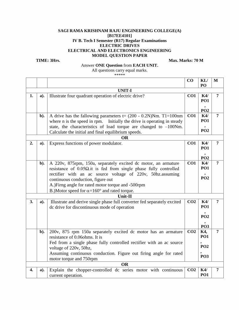
SAGI RAMA KRISHNAM RAJU ENGINEERING COLLEGE(A) [B17EE4101] IV B. Tech I Semester (R17) Regular Examinations ELECTRIC DRIVES ELECTRICAL AND ELECTRONICS ENGINEERING MODEL QUESTION PAPER TIME: 3Hrs. Max. Marks: 70 M Answer ONE Question from EACH UNIT. All questions carry equal marks. ***** CO KL/ PO M UNIT-I 1. a). Illustrate four quadrant operation of electric drive? CO1 K4/ PO1 , PO2 7 b). A drive has the fallowing parameters t= (200 - 0.2N)Nm. T1=100nm where n is the speed in rpm. Initially the drive is operating in steady state, the characteristics of load torque are changed to –100Nm. Calculate the initial and final equilibrium speeds. CO1 K4/ PO1 , PO2 7 OR 2. a). Express functions of power modulator. CO1 K4/ PO1 , PO2 7 b). A 220v, 875rpm, 150a, separately excited dc motor, an armature resistance of 0.05Ω.it is fed from single phase fully controlled rectifier with an ac source voltage of 220v, 50hz.assuming continuous conduction, figure out A.)Firng angle for rated motor torque and -500rpm B.)Motor speed for =160° and rated torque. CO1 K4/ PO1 , PO2 7 Unit-II 3. a). Illustrate and derive single phase full converter fed separately excited dc drive for discontinuous mode of operation CO2 K4/ PO1 , PO2 , PO3 7 b). 200v, 875 rpm 150a separately excited dc motor has an armature resistance of 0.06ohms. It is Fed from a single phase fully controlled rectifier with an ac source voltage of 220v, 50hz, Assuming continuous conduction. Figure out firing angle for rated motor torque and 750rpm CO2 K4, PO1 , PO2 , PO3 7 OR 4. a). Explain the chopper-controlled dc series motor with continuous current operation. CO2 K4/ PO1 7
Transcript of SAGI RAMA KRISHNAM RAJU ENGINEERING COLLEGE(A) …
SAGI RAMA KRISHNAM RAJU ENGINEERING COLLEGE(A)
[B17EE4101]
IV B. Tech I Semester (R17) Regular Examinations
ELECTRIC DRIVES
ELECTRICAL AND ELECTRONICS ENGINEERING
MODEL QUESTION PAPER
TIME: 3Hrs. Max. Marks: 70 M
Answer ONE Question from EACH UNIT.
All questions carry equal marks.
*****
CO KL/
PO
M
UNIT-I
1. a). Illustrate four quadrant operation of electric drive? CO1 K4/
PO1
,
PO2
7
b). A drive has the fallowing parameters t= (200 - 0.2N)Nm. T1=100nm
where n is the speed in rpm. Initially the drive is operating in steady
state, the characteristics of load torque are changed to –100Nm.
Calculate the initial and final equilibrium speeds.
CO1 K4/
PO1
,
PO2
7
OR
2. a). Express functions of power modulator.
CO1 K4/
PO1
,
PO2
7
b). A 220v, 875rpm, 150a, separately excited dc motor, an armature
resistance of 0.05Ω.it is fed from single phase fully controlled
rectifier with an ac source voltage of 220v, 50hz.assuming
continuous conduction, figure out
A.)Firng angle for rated motor torque and -500rpm
B.)Motor speed for =160° and rated torque.
CO1 K4/
PO1
,
PO2
7
Unit-II
3. a). Illustrate and derive single phase full converter fed separately excited
dc drive for discontinuous mode of operation
CO2 K4/
PO1
,
PO2
,
PO3
7
b). 200v, 875 rpm 150a separately excited dc motor has an armature
resistance of 0.06ohms. It is
Fed from a single phase fully controlled rectifier with an ac source
voltage of 220v, 50hz,
Assuming continuous conduction. Figure out firing angle for rated
motor torque and 750rpm
CO2 K4,
PO1
,
PO2
,
PO3
7
OR
4. a). Explain the chopper-controlled dc series motor with continuous
current operation.
CO2 K4/
PO1
7

,
PO2
,
PO3
b). Explain the Closed loop control of DC drive Only Block Diagram
CO2 K4/
PO1
,
PO2
,
PO3
7
Unit-III
5. a). Explain and derive speed torque expression for chopper controlled fed
separately excited dc motor.
CO3 K4/
PO1
,
PO2
,
PO3
7
b). A 230v,960 rpm and 200aseparately excited dcmotor as an armature
resistance of 0.02ohms the motor is fed from a chopper which
provides both motoring and braking operation, the source has a
voltage of 230v assume continuous conduction. Figure out
I. Duty ratio of chopper for motoring operation at rated torque and 350
rpm
ii. Duty ratio of chopper for braking operation at rated torque and 350
rpm
CO3 K4/
PO1
,
PO2
,
PO3
7
OR
6. a). Explain the Chopper controlled DC separately excited motor and DC
series motor
CO3 K4/
PO1
,
PO2
,
PO3
7
b). Explain the Continuous current operation in chopper controlled fed
DCdrives.
CO3 K4/
PO1
,
PO2
,
PO3
7
Unit-IV
7. a). Explain Static Kramer’s Drive with circuit diagram CO4 K4/
PO1
,
PO2
,
PO3
7
b). Explain Static Scherbius Drive with circuit diagram CO4 K4/
PO1
,
PO2
7
,
PO3
OR
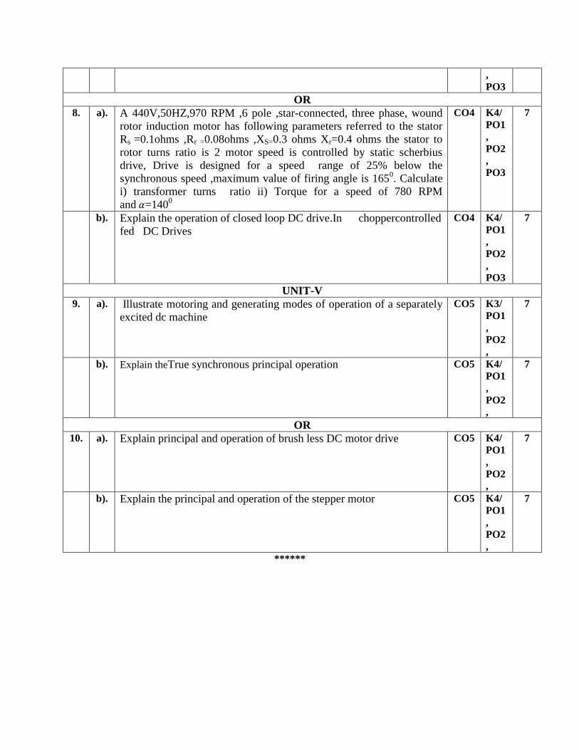
8. a). A 440V,50HZ,970 RPM ,6 pole ,star-connected, three phase, wound
rotor induction motor has following parameters referred to the stator
Rs =0.1ohms ,Rr =0.08ohms ,XS=0.3 ohms Xr=0.4 ohms the stator to
rotor turns ratio is 2 motor speed is controlled by static scherbius
drive, Drive is designed for a speed range of 25% below the
synchronous speed ,maximum value of firing angle is 1650. Calculate
i) transformer turns ratio ii) Torque for a speed of 780 RPM
and 𝛼=1400
CO4 K4/
PO1
,
PO2
,
PO3
7
b). Explain the operation of closed loop DC drive.In choppercontrolled
fed DC Drives
CO4 K4/
PO1
,
PO2
,
PO3
7
UNIT-V
9. a). Illustrate motoring and generating modes of operation of a separately
excited dc machine
CO5 K3/
PO1
,
PO2
,
7
b). Explain theTrue synchronous principal operation
CO5 K4/
PO1
,
PO2
,
7
OR
10. a). Explain principal and operation of brush less DC motor drive
CO5 K4/
PO1
,
PO2
,
7
b). Explain the principal and operation of the stepper motor CO5 K4/
PO1
,
PO2
,
7
******

SAGI RAMA KRISHNAM RAJU ENGINEERING COLLEGE(A)
[B17EE4102]
IV B. Tech I Semester (R17) Regular Examinations
POWER SYSTEM OPERATION AND CONTROL
ELECTRICAL AND ELECTRONICS ENGINEERING
MODEL QUESTION PAPER
TIME: 3Hrs. Max. Marks: 70 M
Answer ONE Question from EACH UNIT.
All questions carry equal marks.
*****
CO KL/
PO
M
UNIT-I
1. a). Derive the equation for optimal load sharing among n units in a power
system by neglecting transmission losses. CO1 K3/
PO1
7
b). A constant 30MW supplied by two 150MW generators, 1 and 2 for which
the respective incremental fuel costs are dC1/dP1=0.1P1+20,
dC2/dP2=0.2P2+25. With P in MW and C in Rs/h. Calculate (i) the most
economical division of load between the generators (ii) the saving in Rs/day
there by obtain compared to equal load sharing between the machines.
CO1 K4/
PO2
7
OR
2. a). Explain the problem of scheduling hydrothermal power plants. Explain the
constraints in the problem. CO1 K3/
PO1
7
b). A power system consists of two 200MW units whose input cost data are
represented by the equations: C1 = 0.03P1 2 + 21P1 + 750 Rs/hour, C2 =
0.5P2 2 + 18P2 + 980 Rs/hour. If the total received power PR = 350 MW,
compute the load division between the units for the most economic
operation.
CO1 K4/
PO2
7
Unit-II
3. a). What is meant by unit commitment problem? Explain the need for unit
commitment problem in operation of power system CO2 K3/
PO1
7
b). With the help of flow chart, explain the solution of unit commitment
problem using dynamic programming. CO2 K3/
PO1
7
OR
4. a). Discuss about different constraints considered in solving a unit commitment
problem CO2 K3/
PO1
7
b). Explain briefly about the different unit commitment solution methods. CO2 K3/
PO1
7
Unit-III
5. a). Discuss the importance of combined load frequency control and economic
dispatch control with a neat block diagram. CO3 K3/
PO1
7
b). Draw the block diagram of uncontrolled two area load frequency control
system and explain the salient features under static condition. CO3 K3/
PO1
7
OR
6. a). Explain the mathematical modeling of speed governing system and derive
the transfer function of speed governor model. State the assumptions made. CO3 K3/
PO1
7
b). A 200 MVA synchronous generator is operating at 3000 rpm, 50Hz. A load
of 40MW is suddenly applied to the machine and the steam valve of the
turbine opens only after 0.4 sec due to the time lag in the generator action.
CO3 K4/
PO2
7
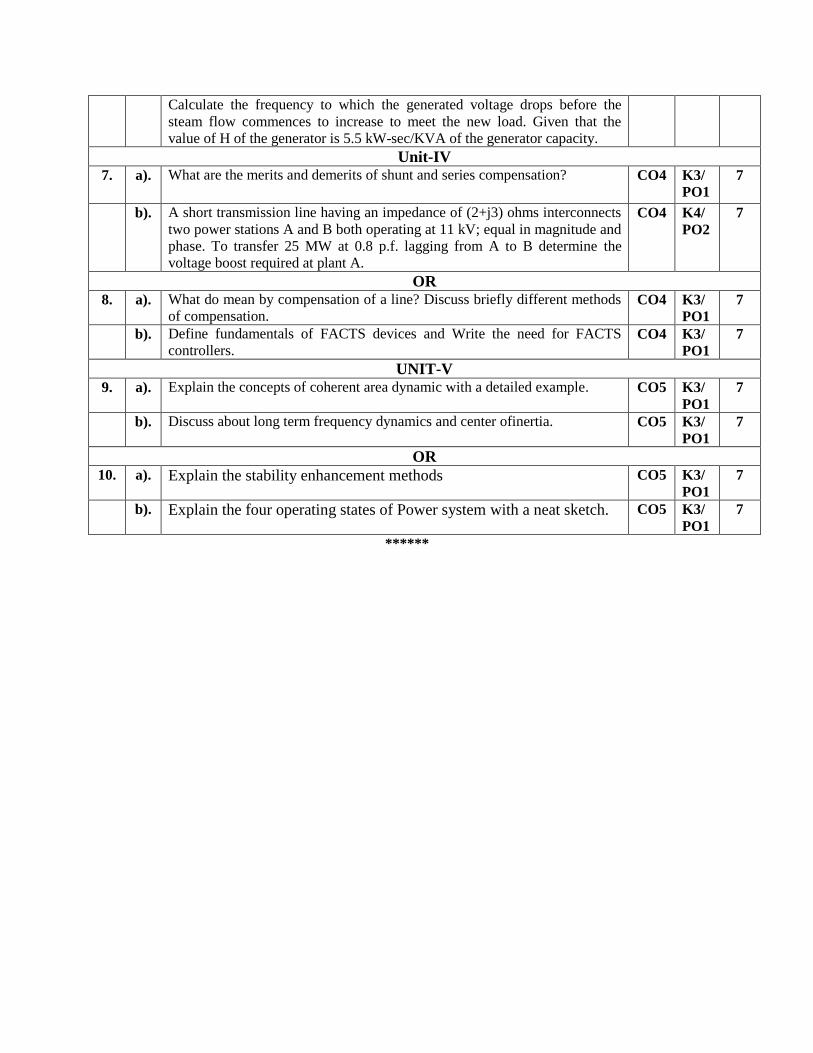
Calculate the frequency to which the generated voltage drops before the
steam flow commences to increase to meet the new load. Given that the
value of H of the generator is 5.5 kW-sec/KVA of the generator capacity.
Unit-IV
7. a). What are the merits and demerits of shunt and series compensation? CO4 K3/
PO1
7
b). A short transmission line having an impedance of (2+j3) ohms interconnects
two power stations A and B both operating at 11 kV; equal in magnitude and
phase. To transfer 25 MW at 0.8 p.f. lagging from A to B determine the
voltage boost required at plant A.
CO4 K4/
PO2
7
OR
8. a). What do mean by compensation of a line? Discuss briefly different methods
of compensation. CO4 K3/
PO1
7
b). Define fundamentals of FACTS devices and Write the need for FACTS
controllers. CO4 K3/
PO1
7
UNIT-V
9. a). Explain the concepts of coherent area dynamic with a detailed example. CO5 K3/
PO1
7
b). Discuss about long term frequency dynamics and center ofinertia. CO5 K3/
PO1
7
OR
10. a). Explain the stability enhancement methods CO5 K3/
PO1
7
b). Explain the four operating states of Power system with a neat sketch. CO5 K3/
PO1
7
******
SAGI RAMA KRISHNAM RAJU ENGINEERING COLLEGE(A)
[B17EE4103]
IV B. Tech I Semester (R17) Regular Examinations
ELECTRIC VEHICLES
ELECTRICAL AND ELECTRONICS ENGINEERING
MODEL QUESTION PAPER
TIME: 3Hrs. Max. Marks: 70 M
Answer ONE Question from EACH UNIT.
All questions carry equal marks.
*****
CO KL/
PO
M
UNIT-I
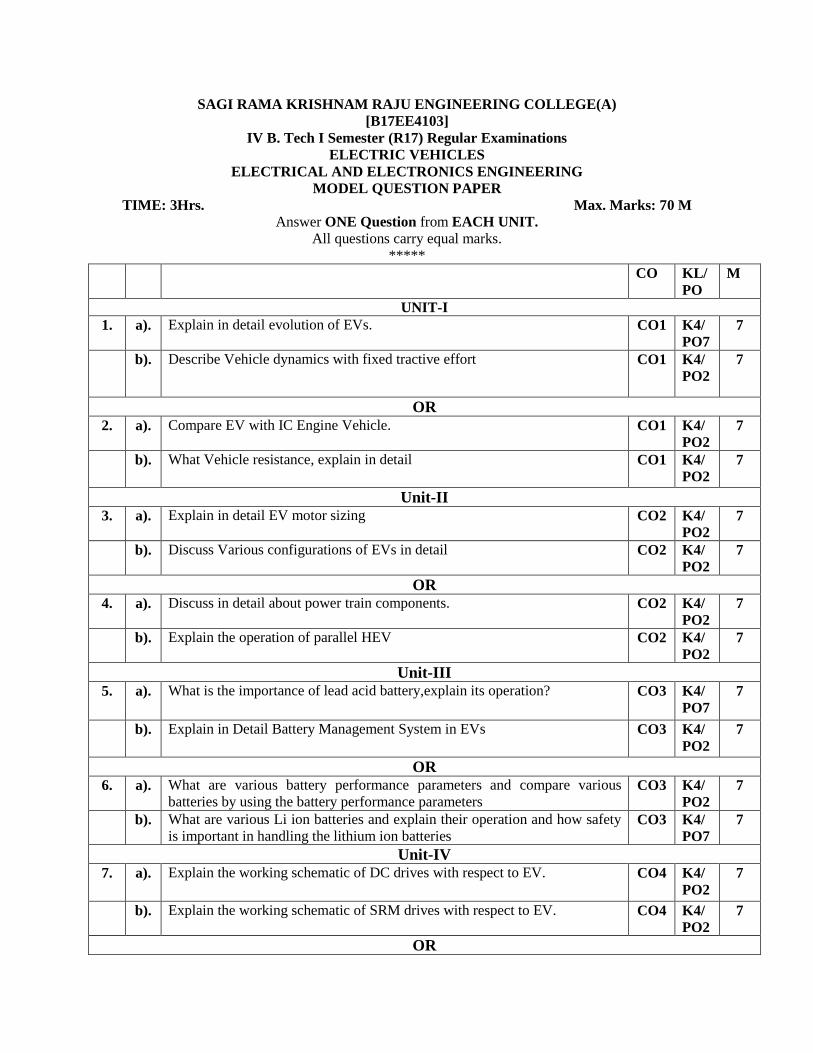
1. a). Explain in detail evolution of EVs. CO1 K4/
PO7 7
b). Describe Vehicle dynamics with fixed tractive effort CO1 K4/
PO2 7
OR
2. a). Compare EV with IC Engine Vehicle. CO1 K4/
PO2 7
b). What Vehicle resistance, explain in detail CO1 K4/
PO2 7
Unit-II
3. a). Explain in detail EV motor sizing CO2 K4/
PO2 7
b). Discuss Various configurations of EVs in detail CO2 K4/
PO2 7
OR
4. a). Discuss in detail about power train components. CO2 K4/
PO2 7
b). Explain the operation of parallel HEV CO2 K4/
PO2 7
Unit-III
5. a). What is the importance of lead acid battery,explain its operation? CO3 K4/
PO7 7
b). Explain in Detail Battery Management System in EVs CO3 K4/
PO2 7
OR
6. a). What are various battery performance parameters and compare various
batteries by using the battery performance parameters CO3 K4/
PO2 7
b). What are various Li ion batteries and explain their operation and how safety
is important in handling the lithium ion batteries CO3 K4/
PO7 7
Unit-IV
7. a). Explain the working schematic of DC drives with respect to EV.
CO4 K4/
PO2 7
b). Explain the working schematic of SRM drives with respect to EV. CO4 K4/
PO2 7
OR
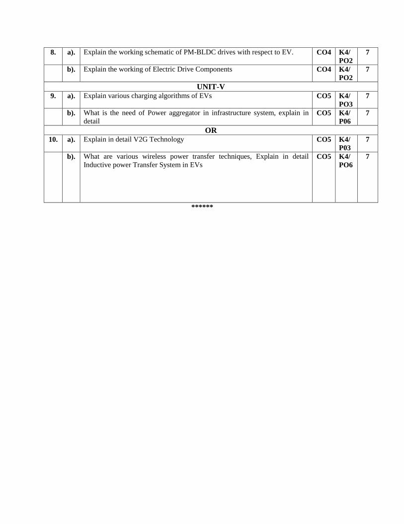
8. a). Explain the working schematic of PM-BLDC drives with respect to EV. CO4 K4/
PO2 7
b). Explain the working of Electric Drive Components CO4 K4/
PO2 7
UNIT-V
9. a). Explain various charging algorithms of EVs CO5 K4/
PO3 7
b). What is the need of Power aggregator in infrastructure system, explain in
detail CO5 K4/
P06 7
OR
10. a). Explain in detail V2G Technology CO5 K4/
P03 7
b). What are various wireless power transfer techniques, Explain in detail
Inductive power Transfer System in EVs CO5 K4/
PO6 7
******
SAGI RAMA KRISHNAM RAJU ENGINEERING COLLEGE(A)
[B17EE4104]
IV B. Tech I Semester (R17) Regular Examinations
Elective-I : OPERATIONS RESEARCH
ELECTRICAL AND ELECTRONICS ENGINEERING
MODEL QUESTION PAPER
TIME: 3Hrs. Max. Marks: 70 M
Answer ONE Question from EACH UNIT.
All questions carry equal marks.
*****
CO KL/
PO M
UNIT-I
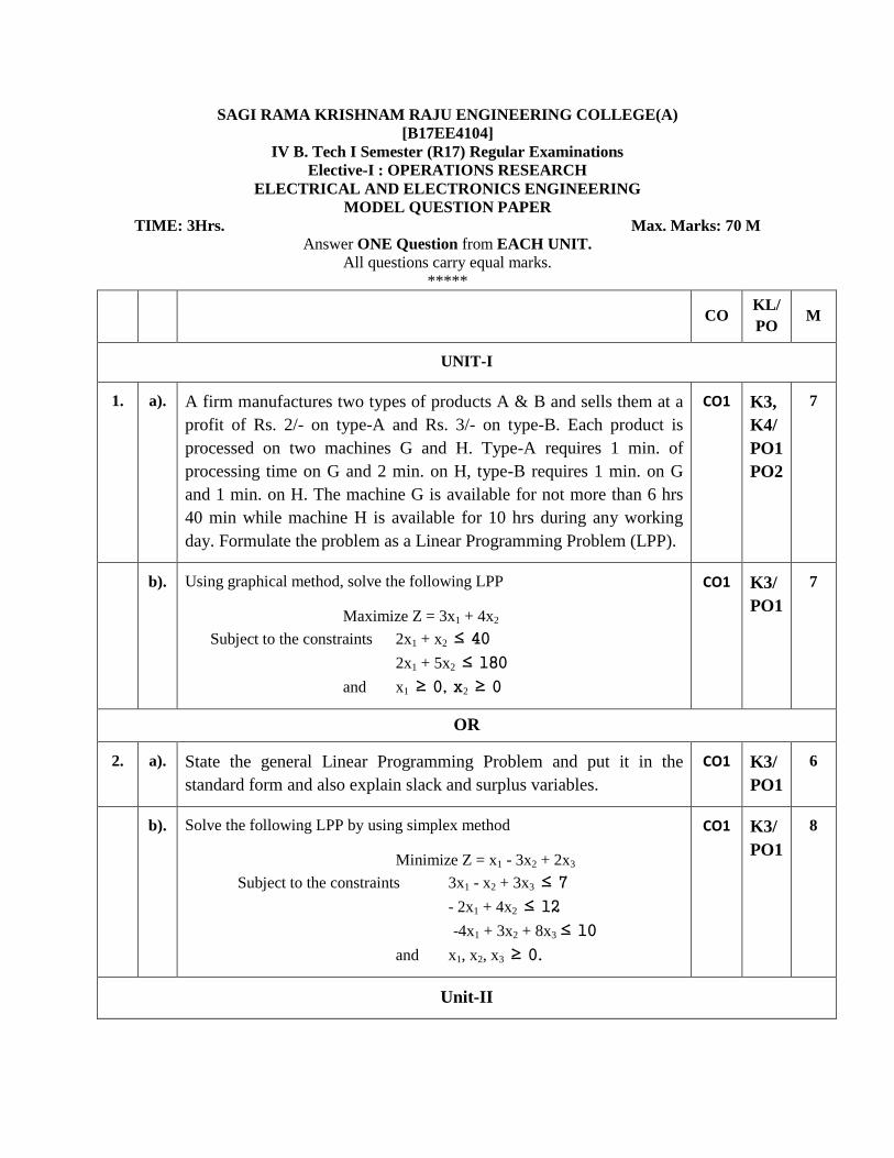
1. a). A firm manufactures two types of products A & B and sells them at a
profit of Rs. 2/- on type-A and Rs. 3/- on type-B. Each product is
processed on two machines G and H. Type-A requires 1 min. of
processing time on G and 2 min. on H, type-B requires 1 min. on G
and 1 min. on H. The machine G is available for not more than 6 hrs
40 min while machine H is available for 10 hrs during any working
day. Formulate the problem as a Linear Programming Problem (LPP).
CO1 K3,
K4/
PO1
PO2
7
b). Using graphical method, solve the following LPP
Maximize Z = 3x1 + 4x2
Subject to the constraints 2x1 + x2 ≤ 40
2x1 + 5x2 ≤ 180
and x1 ≥ 0, x2 ≥ 0
CO1 K3/
PO1
7
OR
2. a). State the general Linear Programming Problem and put it in the
standard form and also explain slack and surplus variables.
CO1 K3/
PO1
6
b). Solve the following LPP by using simplex method
Minimize Z = x1 - 3x2 + 2x3
Subject to the constraints 3x1 - x2 + 3x3 ≤ 7
- 2x1 + 4x2 ≤ 12
-4x1 + 3x2 + 8x3 ≤ 10
and x1, x2, x3 ≥ 0.
CO1 K3/
PO1
8
Unit-II
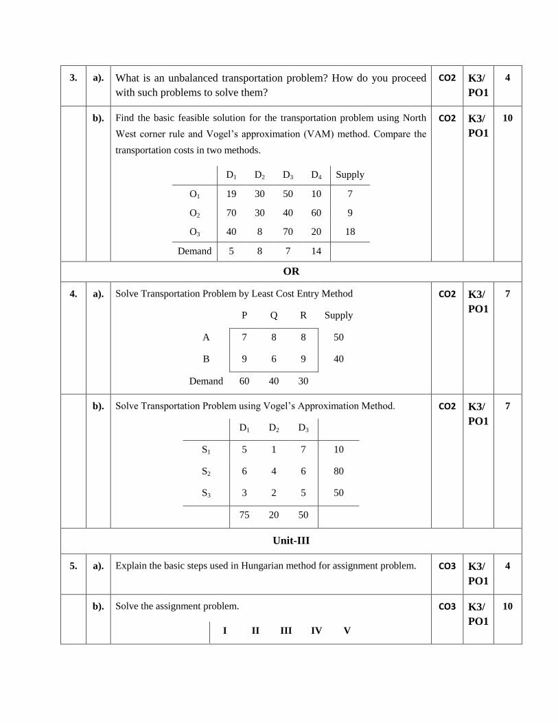
3. a). What is an unbalanced transportation problem? How do you proceed
with such problems to solve them?
CO2 K3/
PO1
4
b). Find the basic feasible solution for the transportation problem using North
West corner rule and Vogel’s approximation (VAM) method. Compare the
transportation costs in two methods.
D1 D2 D3 D4 Supply
O1 19 30 50 10 7
O2 70 30 40 60 9
O3 40 8 70 20 18
Demand 5 8 7 14
CO2 K3/
PO1
10
OR
4. a). Solve Transportation Problem by Least Cost Entry Method
P Q R Supply
A 7 8 8 50
B 9 6 9 40
Demand 60 40 30
CO2 K3/
PO1
7
b). Solve Transportation Problem using Vogel’s Approximation Method.
D1 D2 D3
S1 5 1 7 10
S2 6 4 6 80
S3 3 2 5 50
75 20 50
CO2 K3/
PO1
7
Unit-III
5. a). Explain the basic steps used in Hungarian method for assignment problem. CO3 K3/
PO1
4
b). Solve the assignment problem.
I II III IV V
CO3 K3/
PO1
10
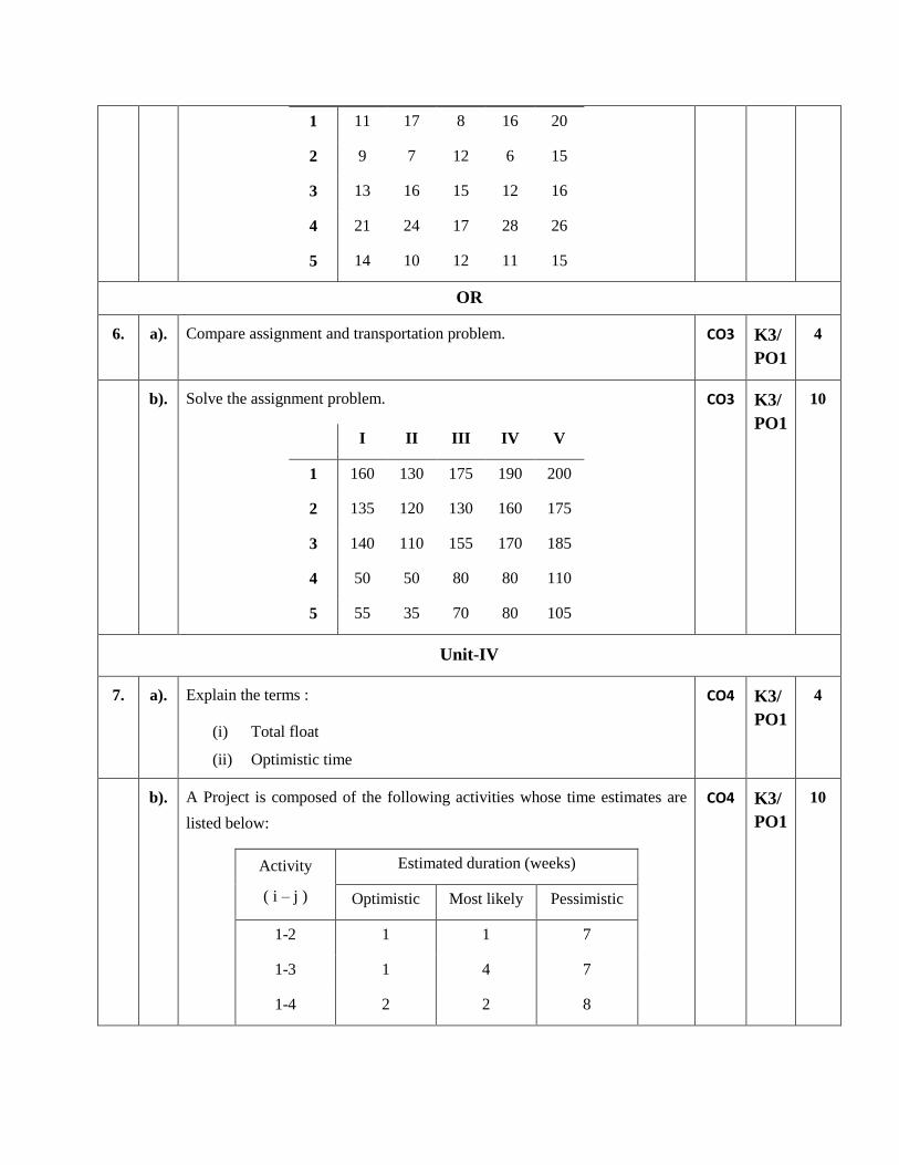
1 11 17 8 16 20
2 9 7 12 6 15
3 13 16 15 12 16
4 21 24 17 28 26
5 14 10 12 11 15
OR
6. a). Compare assignment and transportation problem. CO3 K3/
PO1
4
b). Solve the assignment problem.
I II III IV V
1 160 130 175 190 200
2 135 120 130 160 175
3 140 110 155 170 185
4 50 50 80 80 110
5 55 35 70 80 105
CO3 K3/
PO1
10
Unit-IV
7. a). Explain the terms :
(i) Total float
(ii) Optimistic time
CO4 K3/
PO1
4
b). A Project is composed of the following activities whose time estimates are
listed below:
Activity
( i – j )
Estimated duration (weeks)
Optimistic Most likely Pessimistic
1-2 1 1 7
1-3 1 4 7
1-4 2 2 8
CO4 K3/
PO1
10

2-5 1 1 1
3-5 2 5 14
4-6 2 5 8
5-6 3 6 15
(a) Draw the project network and calculate the early and late
occurrence times for each event.
(b) Find the critical path and its standard deviation.
(c) What is the probability that the project will be completed 4
weeks earlier than expected?
OR
8. a). Explain Fulkerson’s rule with suitable example. CO4 K3/
PO1
4
b). A Project is composed of the following activities whose time estimates are
listed below:
Activity Predecessors Estimated duration
Optimistic Most likely Pessimistic
A - 5 6 7
B - 1 3 5
C - 1 4 7
D A 1 2 3
E B 1 2 9
F C 1 5 9
G C 2 2 8
H E, F 4 4 10
I D 2 5 8
J H, G 2 2 8
(a) Draw the project network
(b) Calculate expected time and variance of each activity.
CO4 K3/
PO1
10

(c) Find the critical path and its standard deviation.
UNIT-V
9. a). Distinguish between a pure strategy and mixed strategy of a rectangular
game.
CO5 K3/
PO1
4
b). Solve the following game graphically,
Player-B
Player-A 3 -3 4
-1 1 -3
CO5 K3,
K4/
PO1
PO2
10
OR
10. a). What is a two-person zero-sum game? Define the saddle point of such a
game.
CO5 K3/
PO1
4
b). Solve the following game, using the concept of dominance
Player-B
B1 B2 B3 B4
Player-A
A1 8 10 9 14
A2 10 11 8 12
A3 13 12 14 13
CO5 K3,
K4/
PO1
PO2
10
******
SAGI RAMA KRISHNAM RAJU ENGINEERING COLLEGE(A)
[B17EE4105]
IV B. Tech I Semester (R17) Regular Examinations
Elective-I: FLEXIBLE AC TRANSMISSION SYSTEM
ELECTRICAL AND ELECTRONICS ENGINEERING
MODEL QUESTION PAPER

TIME: 3Hrs. Max. Marks: 70 M
Answer ONE Question from EACH UNIT.
All questions carry equal marks.
*****
CO KL/
PO
M
UNIT-I
1. a). Outline the necessity of reactive power in power system? CO1 K3/
PO1
7
b). Explain the problems associated with synchronous condenser? CO1 K3/
PO1
7
OR
2. a). Explain the operation of Thyristor-Switched Capacitor (TSC). CO2 K4/
PO2
7
b). Explain the operation of Thyristor-Controlled Reactor (TCR). CO2 K4/
PO2
7
Unit-II
3. a). Design the SVC voltage regulator based on system gain. CO3 K4/
PO3
14
OR
4. a). Explain the Influence of SVC on system voltage CO3 K4/
PO2
7
b). Outline the Enhancement of transient stability using SVC. CO4 K4/
PO2
7
Unit-III
5. Explain the operation of a STATCOM? Also derive the steady state model of
it. CO3 K4/
PO2
14
OR
6. a). Compare between SVC and STATCOM. CO3 K4/
PO2
7
b). With a neat block diagram, explain the Sub-Synchronous Resonance (SSR)
Mitigation by using STATCOM. CO4 K4/
PO2
7
Unit-IV
7. Explain the operation of TCSC. Also explain different modes of it. CO3 K4/
PO2
14
OR
8. a). Discuss the variable reactance model of TCSC. CO3 K4/
PO2
7
b). Discuss the system damping improvement using thyristor-controlled series
capacitor (TCSC). CO5 K4/
PO2
7
UNIT-V
9. a). With a neat block diagram, explain the Sub-Synchronous Resonance
(SSR) Mitigation by using SSSC. CO5 K4/
PO2
7
b). Compare between SSSC and TCSC. CO3 K4/
PO2
7
OR
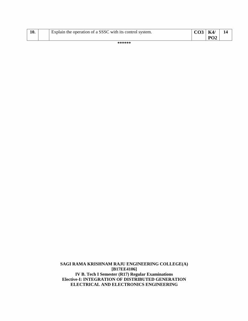
10. Explain the operation of a SSSC with its control system. CO3 K4/
PO2
14
******
SAGI RAMA KRISHNAM RAJU ENGINEERING COLLEGE(A)
[B17EE4106]
IV B. Tech I Semester (R17) Regular Examinations
Elective-I: INTEGRATION OF DISTRIBUTED GENERATION
ELECTRICAL AND ELECTRONICS ENGINEERING
MODEL QUESTION PAPER
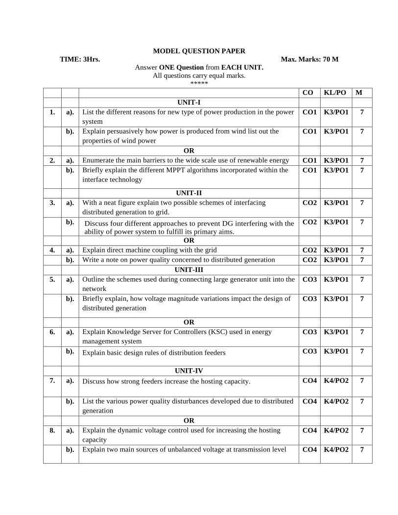
TIME: 3Hrs. Max. Marks: 70 M
Answer ONE Question from EACH UNIT.
All questions carry equal marks.
*****
CO KL/PO M
UNIT-I
1. a). List the different reasons for new type of power production in the power
system
CO1 K3/PO1 7
b). Explain persuasively how power is produced from wind list out the
properties of wind power
CO1 K3/PO1 7
OR
2. a). Enumerate the main barriers to the wide scale use of renewable energy CO1 K3/PO1 7
b). Briefly explain the different MPPT algorithms incorporated within the
interface technology
CO1 K3/PO1 7
UNIT-II
3. a). With a neat figure explain two possible schemes of interfacing
distributed generation to grid.
CO2 K3/PO1 7
b). Discuss four different approaches to prevent DG interfering with the
ability of power system to fulfill its primary aims.
CO2 K3/PO1 7
OR
4. a). Explain direct machine coupling with the grid CO2 K3/PO1 7
b). Write a note on power quality concerned to distributed generation CO2 K3/PO1 7
UNIT-III
5. a). Outline the schemes used during connecting large generator unit into the
network
CO3 K3/PO1 7
b). Briefly explain, how voltage magnitude variations impact the design of
distributed generation
CO3 K3/PO1 7
OR
6. a). Explain Knowledge Server for Controllers (KSC) used in energy
management system
CO3 K3/PO1 7
b). Explain basic design rules of distribution feeders
CO3 K3/PO1 7
UNIT-IV
7. a). Discuss how strong feeders increase the hosting capacity.
CO4 K4/PO2 7
b). List the various power quality disturbances developed due to distributed
generation
CO4 K4/PO2 7
OR
8. a). Explain the dynamic voltage control used for increasing the hosting
capacity
CO4 K4/PO2 7
b). Explain two main sources of unbalanced voltage at transmission level CO4 K4/PO2 7
******
SAGI RAMA KRISHNAM RAJU ENGINEERING COLLEGE(A)
[B17EE4107]
IV B. Tech I Semester (R17) Regular Examinations
Elective-II: HIGH VOLTAGE ENGINEERING
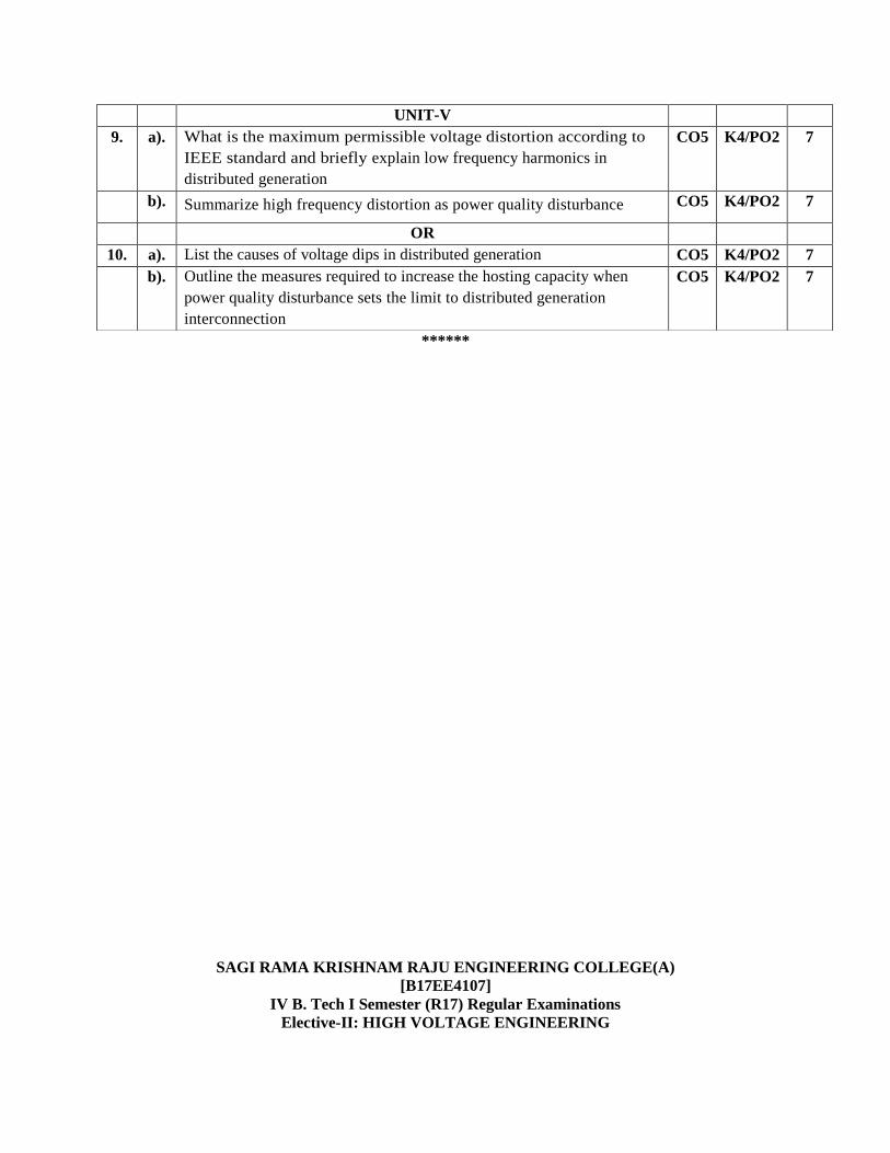
UNIT-V
9. a). What is the maximum permissible voltage distortion according to
IEEE standard and briefly explain low frequency harmonics in
distributed generation
CO5 K4/PO2 7
b). Summarize high frequency distortion as power quality disturbance CO5 K4/PO2 7
OR
10. a). List the causes of voltage dips in distributed generation CO5 K4/PO2 7
b). Outline the measures required to increase the hosting capacity when
power quality disturbance sets the limit to distributed generation
interconnection
CO5 K4/PO2 7
ELECTRICAL AND ELECTRONICS ENGINEERING
MODEL QUESTION PAPER
TIME: 3Hrs. Max. Marks: 70 M
Answer ONE Question from EACH UNIT.
All questions carry equal marks.
******
CO KL/PO M
UNIT-I
1. a). Explain the importance of electric field stress developed in
insulatingmaterials. [8]
CO1 K2/
PO1
7
b). Writetheadvantagesanddisadvantagesofthevariousnumericalmethods. CO1 K2/
PO1
7
OR
2. a). Explain uniform and non–uniform field configuration of electrodes. CO1 K2/
PO1
7
b). Define finite element method, briefly explain the four steps involved in
thefinite element analysis of any problem. CO1 K4/
PO2
7
UNIT-II
3. a). Explain Townsend’s current growth equation. CO2 K4/
PO2
7
b). Explain briefly about electro mechanical breakdown. CO2 K2/
PO1
7
OR
4. a). Discuss about Paschen’s law briefly. CO2 K4/
PO2
7
b). Explain Breakdown in composite dielectrics CO2 K2/
PO1
7
UNIT-III
5. a). With a neat diagram explain the working of Impulse Voltage
generator.
CO3 K4/
PO2
7
b). Give the classification of different forms of high voltages. CO3 K2/
PO2
7
OR
6. a). With a neat diagram explain the working of Vande Graff Generators. CO3 K4/
PO2
7
b). Explain tripping and control of impulse generators CO3 K4/
PO2
7
UNIT-IV
7. a). Explain the measurement of high dc voltages by connecting very high
resistance in series with a micrometer. Also mention limitations in the
series resistance.
CO4 K4/
PO2
7
b). Explain how Impulse current can be Measured.
CO4 K4/
PO2
7
OR
8. a). Explain the different methods of high d.c, a.c and impulse current
measurement with their relative merits demerits. CO4 K2/
PO2
7

******
SAGI RAMA KRISHNAM RAJU ENGINEERING COLLEGE(A)
[B17EE4108]
IV B. Tech I Semester (R17) Regular Examinations
Elective-II: ELECTRIC POWER QUALITY ELECTRICAL AND ELECTRONICS ENGINEERING
b). Explain with neat diagram the principle of operation of an electrostatic
voltmeter. Discuss its advantages and limitations for high voltage
measurements.
CO4 K4/
PO2
7
UNIT-V
9. a). Draw the schematic diagram of electrostatic precipitator and explain. CO5 K4/
PO2
7
b). Explain the industrial applications of high energy rate pulsed power
generator. CO5 K4/
PO2
7
OR
10. a). Explain Wheatstone bridge arrangement for resistivity measurement. CO5 K4/
PO2
7
b). Draw the circuit for partial discharge measurement and explain how it
works. CO5 K4/
PO2
7
MODEL QUESTION PAPER
TIME: 3Hrs. Max. Marks: 70 M
Answer ONE Question from EACH UNIT.
All questions carry equal marks.
*****
CO KL/
PO
M
UNIT-I
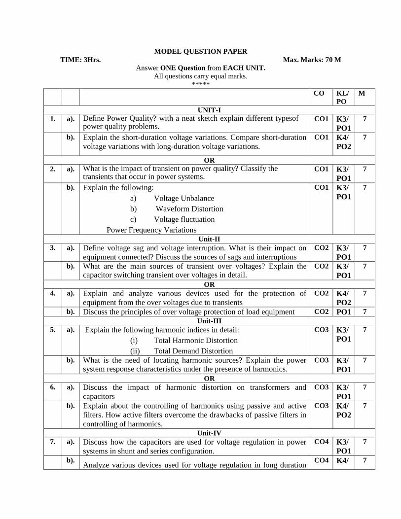
1. a). Define Power Quality? with a neat sketch explain different typesof power quality problems.
CO1 K3/
PO1
7
b). Explain the short-duration voltage variations. Compare short-duration
voltage variations with long-duration voltage variations.
CO1 K4/
PO2
7
OR
2. a). What is the impact of transient on power quality? Classify the transients that occur in power systems.
CO1 K3/
PO1
7
b). Explain the following: a) Voltage Unbalance b) Waveform Distortion c) Voltage fluctuation
Power Frequency Variations
CO1 K3/
PO1
7
Unit-II
3. a). Define voltage sag and voltage interruption. What is their impact on
equipment connected? Discuss the sources of sags and interruptions
CO2 K3/
PO1
7
b). What are the main sources of transient over voltages? Explain the capacitor switching transient over voltages in detail.
CO2 K3/
PO1
7
OR
4. a). Explain and analyze various devices used for the protection of
equipment from the over voltages due to transients
CO2 K4/
PO2
7
b). Discuss the principles of over voltage protection of load equipment CO2 PO1 7
Unit-III
5. a). Explain the following harmonic indices in detail: (i) Total Harmonic Distortion (ii) Total Demand Distortion
CO3 K3/
PO1
7
b). What is the need of locating harmonic sources? Explain the power system response characteristics under the presence of harmonics.
CO3 K3/
PO1
7
OR
6. a). Discuss the impact of harmonic distortion on transformers and
capacitors
CO3 K3/
PO1
7
b). Explain about the controlling of harmonics using passive and active
filters. How active filters overcome the drawbacks of passive filters in
controlling of harmonics.
CO3 K4/
PO2
7
Unit-IV
7. a). Discuss how the capacitors are used for voltage regulation in power
systems in shunt and series configuration.
CO4 K3/
PO1
7
b). Analyze various devices used for voltage regulation in long duration
CO4 K4/ 7
voltage variation PO2
OR
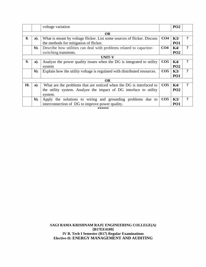
8. a). What is meant by voltage flicker. List some sources of flicker. Discuss
the methods for mitigation of flicker.
CO4 K3/
PO1
7
b). Describe how utilities can deal with problems related to capacitor-
switching transients.
CO4 K4/
PO2
7
UNIT-V
9. a). Analyze the power quality issues when the DG is integrated to utility
system
CO5 K4/
PO2
7
b). Explain how the utility voltage is regulated with distributed resources. CO5 K3/
PO1
7
OR
10. a). What are the problems that are noticed when the DG is interfaced to
the utility system. Analyze the impact of DG interface to utility
system.
CO5 K4/
PO2
7
b). Apply the solutions to wiring and grounding problems due to
interconnection of DG to improve power quality.
CO5 K3/
PO1
7
******
SAGI RAMA KRISHNAM RAJU ENGINEERING COLLEGE(A)
[B17EE4109]
IV B. Tech I Semester (R17) Regular Examinations
Elective-II: ENERGY MANAGEMENT AND AUDITING

ELECTRICAL AND ELECTRONICS ENGINEERING
MODEL QUESTION PAPER
TIME: 3Hrs. Max. Marks: 70 M
Answer ONE Question from EACH UNIT.
All questions carry equal marks.
*****
CO KL/
PO
M
UNIT-I
1. a). What is energy audit? What are the different types of audit? CO1 K3/
PO1
7
b). What is a load profile? Explain about different types of load profile. CO1 K3/
PO1
7
OR
2. a). What is an energy management? Explain the importance of energy
management. CO1 K3/
PO1
7
b). List the types of energy conservation methods and discuss their merits
and demerits. CO1 K3/
PO1
7
Unit-II
3. a). Discuss about the flood lighting scheme. CO2 K3/
PO1
7
b). Brief out the conservation measures in lighting schemes. CO2 K4/
PO2
7
OR
4. a). Explain the significance of polar curve. CO2 K4/
PO2
7
b). How the existing lighting system is replaced for the improvement? CO2 K4/
PO2
7
Unit-III
5. a). Compare the features of static capacitor and synchronous condenser
used for power factor correction. CO3 K4/
PO2
7
b). Discuss the effect of non linear loads on power factor. CO3 K4/
PO2
7
OR
6. a). Discuss the vector diagram for a system where capacitor improves the
power factor CO3 K3/
PO1
7
b). Define harmonics. Discuss the effect of harmonics on the system
power factor. CO3 K3/
PO1
7
Unit-IV
7. a). Explain the principle of present worth method with an example. CO4 K4/
PO2
7
b). Discuss the merits and demerits of time value of money CO4 K3/
PO1
7
OR
8. a). Explain the principle of life cycle costing analysis with an example CO4 K4/
PO2
7
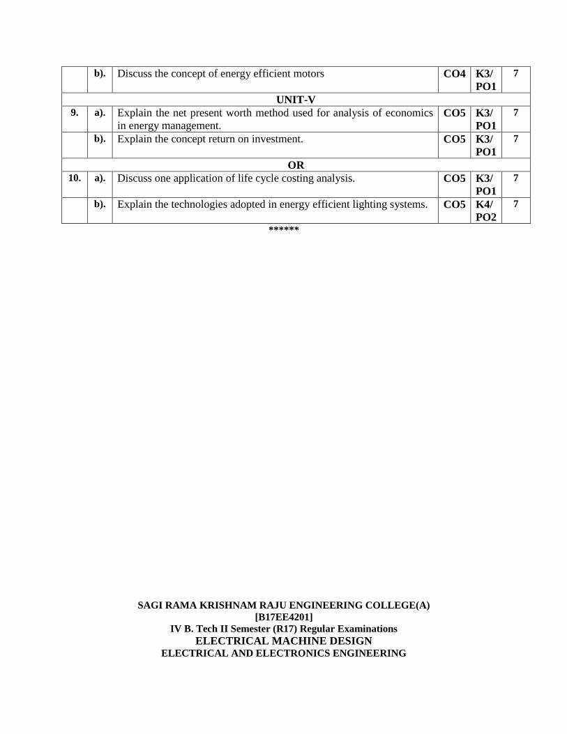
b). Discuss the concept of energy efficient motors CO4 K3/
PO1
7
UNIT-V
9. a). Explain the net present worth method used for analysis of economics
in energy management. CO5 K3/
PO1
7
b). Explain the concept return on investment. CO5 K3/
PO1
7
OR
10. a). Discuss one application of life cycle costing analysis. CO5 K3/
PO1
7
b). Explain the technologies adopted in energy efficient lighting systems. CO5 K4/
PO2
7
******
SAGI RAMA KRISHNAM RAJU ENGINEERING COLLEGE(A)
[B17EE4201]
IV B. Tech II Semester (R17) Regular Examinations
ELECTRICAL MACHINE DESIGN ELECTRICAL AND ELECTRONICS ENGINEERING
MODEL QUESTION PAPER
TIME: 3Hrs. Max. Marks: 70 M
Answer ONE Question from EACH UNIT.
All questions carry equal marks.
******
CO KL/PO M
UNIT-I
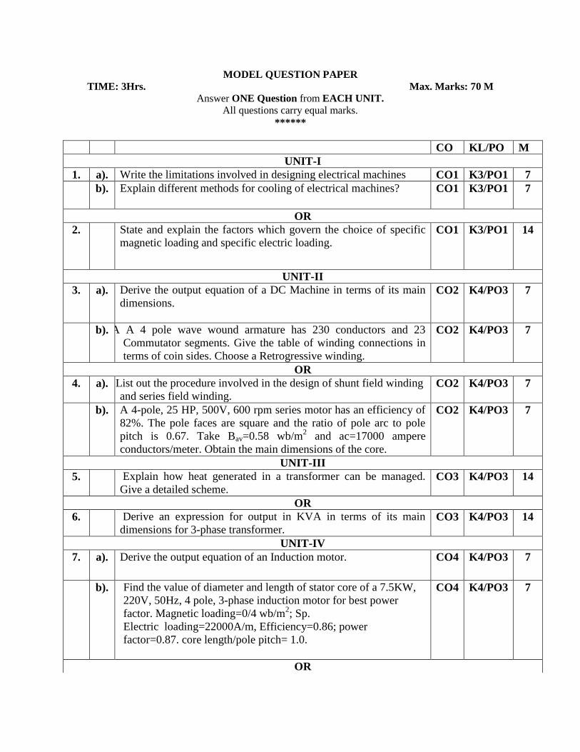
1. a). Write the limitations involved in designing electrical machines CO1 K3/PO1 7
b). Explain different methods for cooling of electrical machines? CO1 K3/PO1 7
OR
2. State and explain the factors which govern the choice of specific
magnetic loading and specific electric loading. CO1 K3/PO1 14
UNIT-II
3. a). Derive the output equation of a DC Machine in terms of its main
dimensions.
CO2 K4/PO3 7
b). A 4 pA A 4 pole wave wound armature has 230 conductors and 23
Commutator segments. Give the table of winding connections in
terms of coin sides. Choose a Retrogressive winding.
CO2 K4/PO3 7
OR
4. a). List out the procedure involved in the design of shunt field winding
and series field winding. CO2 K4/PO3 7
b). A 4-pole, 25 HP, 500V, 600 rpm series motor has an efficiency of
82%. The pole faces are square and the ratio of pole arc to pole
pitch is 0.67. Take Bav=0.58 wb/m2 and ac=17000 ampere
conductors/meter. Obtain the main dimensions of the core.
CO2 K4/PO3 7
UNIT-III
5. Explain how heat generated in a transformer can be managed.
Give a detailed scheme. CO3 K4/PO3 14
OR
6. Derive an expression for output in KVA in terms of its main
dimensions for 3-phase transformer. CO3 K4/PO3 14
UNIT-IV
7. a). Derive the output equation of an Induction motor. CO4 K4/PO3 7
b). Find the value of diameter and length of stator core of a 7.5KW,
220V, 50Hz, 4 pole, 3-phase induction motor for best power
factor. Magnetic loading=0/4 wb/m2; Sp.
Electric loading=22000A/m, Efficiency=0.86; power
factor=0.87. core length/pole pitch= 1.0.
CO4 K4/PO3 7
OR
SAGI RAMA KRISHNAM RAJU ENGINEERING COLLEGE(A)
[B17EE4202]
IV B. Tech II Semester (R17) Regular Examinations
Elective-III: ELECTRICAL DISTRIBUTION SYSTEMS
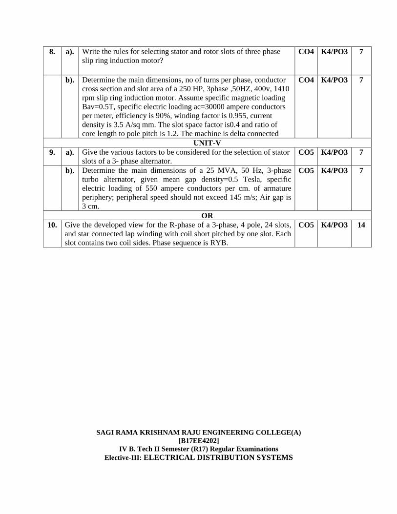
8. a). Write the rules for selecting stator and rotor slots of three phase
slip ring induction motor? CO4 K4/PO3 7
b). Determine the main dimensions, no of turns per phase, conductor
cross section and slot area of a 250 HP, 3phase ,50HZ, 400v, 1410
rpm slip ring induction motor. Assume specific magnetic loading
Bav=0.5T, specific electric loading ac=30000 ampere conductors
per meter, efficiency is 90%, winding factor is 0.955, current
density is 3.5 A/sq mm. The slot space factor is0.4 and ratio of
core length to pole pitch is 1.2. The machine is delta connected
CO4 K4/PO3 7
UNIT-V
9. a). Give the various factors to be considered for the selection of stator
slots of a 3- phase alternator. CO5 K4/PO3 7
b). Determine the main dimensions of a 25 MVA, 50 Hz, 3-phase
turbo alternator, given mean gap density=0.5 Tesla, specific
electric loading of 550 ampere conductors per cm. of armature
periphery; peripheral speed should not exceed 145 m/s; Air gap is
3 cm.
CO5 K4/PO3 7
OR
10. Give the developed view for the R-phase of a 3-phase, 4 pole, 24 slots,
and star connected lap winding with coil short pitched by one slot. Each
slot contains two coil sides. Phase sequence is RYB.
CO5 K4/PO3 14

ELECTRICAL AND ELECTRONICS ENGINEERING
MODEL QUESTION PAPER
TIME: 3Hrs. Max. Marks: 70 M
Answer ONE Question from EACH UNIT.
All questions carry equal marks.
*****
CO KL/
PO
M
UNIT-I
1. a). Define and explain the following terms with suitable examples: (i)
load factor, (ii) loss factor, (iii) Contribution factor and (iv) diversity
factor.
CO1 K3/
PO1
7
b). A substation supplied the following loads: 175MW, 100MW, 75MW,
50MW and 10MW. The station has a maximum demand of 250MW.
Determine the following, if annual load factor of the station is 45% (i)
Number of units supplied annually (ii) Diversity factor (iii) Demand
factor.
CO1 K4/
PO2
7
OR
2. a). Obtain the relation between load factor and lossfactor.
CO1 K3/
PO1
7
b). A substation is to supply three regions of loads whose
maximum values are
6000kW,10000kWand5000kW.Thediversityfactoroftheloadatthesub
stationis
1.5 and the average annual load factor is 0.65. Calculate the peak
demand on the substation and annual energy supplied fromthe
substation.
CO1 K4/
PO2
7
Unit-II
3. a). What are the various factors that are to be considered in selecting
primary feeder rating? Give a neat sketch of typical primary
distribution feeder.
CO2 K3/
PO1
7
b). Derive the percentage voltage drop of a substation service area with
‘n’ number of primary feeders.
CO2 K3/
PO1
7
OR
4. a).
What are the types of basic distribution system?Explain. CO2 K3/
PO1
7
b). Draw the single line diagram of radial type primary feeder and
mention the factors that influence the selection ofprimaryfeeder.
CO2 K3/
PO1
7
Unit-III
5. a). Obtain the expression for voltage drop and power loss for uniformly
radial type distribution load.
CO3 K4/
PO2
7
b). If Z1 = 15 -300 , Z2 = 20 800 and Z3 = 20 +900 are the
impedances connected in the form of delta and the supply voltage is
CO3 K4/
PO2
7
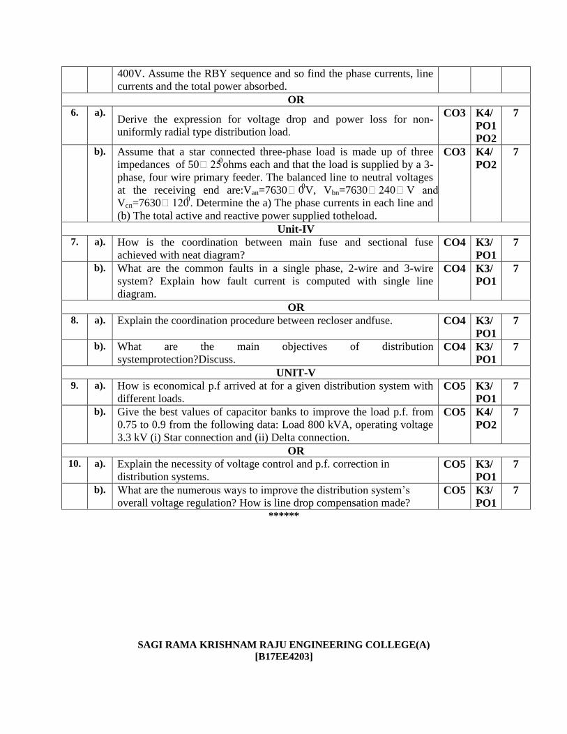
400V. Assume the RBY sequence and so find the phase currents, line
currents and the total power absorbed.
OR
6. a). Derive the expression for voltage drop and power loss for non-
uniformly radial type distribution load.
CO3 K4/
PO1
PO2
7
b). Assume that a star connected three-phase load is made up of three
impedances of 50250ohms each and that the load is supplied by a 3-
phase, four wire primary feeder. The balanced line to neutral voltages
at the receiving end are:Van=763000V, Vbn=7630240V and
Vcn=76301200. Determine the a) The phase currents in each line and
(b) The total active and reactive power supplied totheload.
CO3 K4/
PO2
7
Unit-IV
7. a). How is the coordination between main fuse and sectional fuse
achieved with neat diagram?
CO4 K3/
PO1
7
b). What are the common faults in a single phase, 2-wire and 3-wire
system? Explain how fault current is computed with single line
diagram.
CO4 K3/
PO1
7
OR
8. a). Explain the coordination procedure between recloser andfuse. CO4 K3/
PO1
7
b). What are the main objectives of distribution
systemprotection?Discuss. CO4 K3/
PO1
7
UNIT-V
9. a). How is economical p.f arrived at for a given distribution system with
different loads. CO5 K3/
PO1
7
b). Give the best values of capacitor banks to improve the load p.f. from
0.75 to 0.9 from the following data: Load 800 kVA, operating voltage
3.3 kV (i) Star connection and (ii) Delta connection.
CO5 K4/
PO2
7
OR
10. a). Explain the necessity of voltage control and p.f. correction in
distribution systems. CO5 K3/
PO1
7
b). What are the numerous ways to improve the distribution system’s
overall voltage regulation? How is line drop compensation made? CO5 K3/
PO1
7
******
SAGI RAMA KRISHNAM RAJU ENGINEERING COLLEGE(A)
[B17EE4203]

IV B. Tech II Semester (R17) Regular Examinations
Elective-III: UTILIZATION OF ELECTRICAL ENERGY& TRACTION
ELECTRICAL AND ELECTRONICS ENGINEERING
MODEL QUESTION PAPER
TIME: 3Hrs. Max. Marks: 70 M
Answer ONE Question from EACH UNIT.
All questions carry equal marks.
*****
CO KL/
PO
M
UNIT-I
1. a). Explain the advantages of electric heating.. CO1 K3/
PO1
7
b). With a neat diagram, explain the working of metallic Arc welding. CO1 K3/
PO1
7
OR
2. a). Compare between AC welding and DC welding CO1 K3/
PO1
7
b). Explain the principle of dielectric heating. Also write the applications
of Dielectric heating. CO1 K3/
PO1
7
UNIT-II
3. a). Define inverse square law and cosine cube law of illumination. CO2 K3/
PO1
7
b). A lamp giving 300 C.P in all directions below horizontal is suspended
2m above the centre of a square table of 1m side. Calculate the
maximum and minimum illumination on the surface of the table.
CO2 K4/
PO2
7
OR
4. a). What is photometry? Explain photovoltaic method of photometry. CO2 K3/
PO1
7
b). A lamp with mean spherical candle power of 1000 is suspended at a
height of 1.2m. Determine i) total flux emitted by the lamp ii) the
illumination just below the lamp.
CO2 K4/
PO2
7
UNIT-III
5. a). Sketch the typical speed-time curves for mainline service and
suburban service with electric traction. CO3 K3/
PO1
7
b). Explain Regenerative braking applied to 3- Φ induction motor. Also
mention their advantages. CO3 K3/
PO1
7
OR
6. a). List and explain different braking schemes used in electric traction
drives. Also mention their advantages and disadvantages. CO3 K4/
PO2
14
UNIT-IV
7. a). What is specific energy consumption of a train? Explain various
factors affecting it. CO4 K3/
PO1
7
b). A suburban train runs with an average speed of 36 kmph between two
stations 1.8 km apart. The values of acceleration and retardation are
1.8 kmphps and 3.6 kmphps. Calculate the maximum speed of the
CO4 K4/
PO2
7
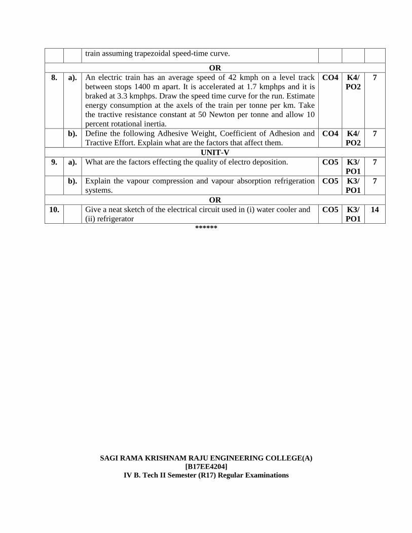
train assuming trapezoidal speed-time curve.
OR
8. a). An electric train has an average speed of 42 kmph on a level track
between stops 1400 m apart. It is accelerated at 1.7 kmphps and it is
braked at 3.3 kmphps. Draw the speed time curve for the run. Estimate
energy consumption at the axels of the train per tonne per km. Take
the tractive resistance constant at 50 Newton per tonne and allow 10
percent rotational inertia.
CO4 K4/
PO2
7
b). Define the following Adhesive Weight, Coefficient of Adhesion and
Tractive Effort. Explain what are the factors that affect them. CO4 K4/
PO2
7
UNIT-V
9. a). What are the factors effecting the quality of electro deposition. CO5 K3/
PO1
7
b). Explain the vapour compression and vapour absorption refrigeration
systems. CO5 K3/
PO1
7
OR
10. Give a neat sketch of the electrical circuit used in (i) water cooler and
(ii) refrigerator CO5 K3/
PO1
14
******
SAGI RAMA KRISHNAM RAJU ENGINEERING COLLEGE(A)
[B17EE4204]
IV B. Tech II Semester (R17) Regular Examinations
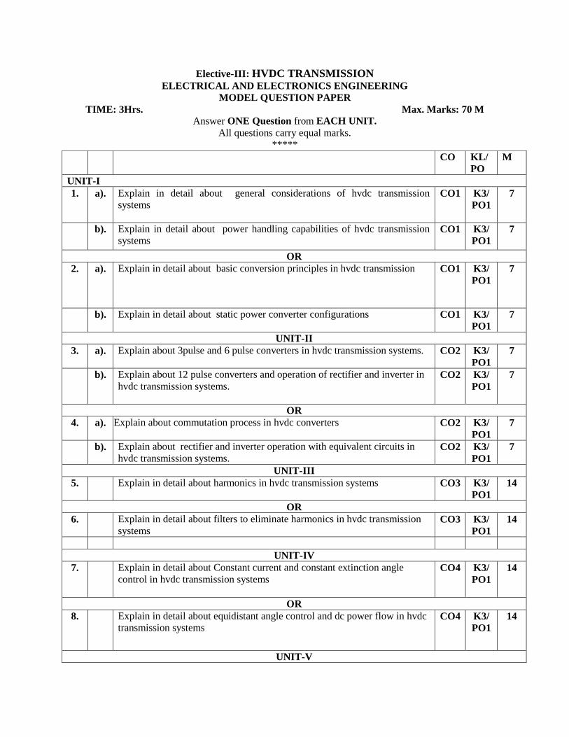
Elective-III: HVDC TRANSMISSION ELECTRICAL AND ELECTRONICS ENGINEERING
MODEL QUESTION PAPER
TIME: 3Hrs. Max. Marks: 70 M
Answer ONE Question from EACH UNIT.
All questions carry equal marks.
*****
CO KL/
PO
M
UNIT-I
1. a). Explain in detail about general considerations of hvdc transmission
systems
CO1 K3/
PO1
7
b). Explain in detail about power handling capabilities of hvdc transmission
systems CO1 K3/
PO1
7
OR
2. a). Explain in detail about basic conversion principles in hvdc transmission CO1 K3/
PO1
7
b). Explain in detail about static power converter configurations CO1 K3/
PO1
7
UNIT-II
3. a). Explain about 3pulse and 6 pulse converters in hvdc transmission systems.
CO2 K3/
PO1
7
b). Explain about 12 pulse converters and operation of rectifier and inverter in
hvdc transmission systems.
CO2 K3/
PO1
7
OR
4. a). Explain about commutation process in hvdc converters
CO2 K3/
PO1
7
b). Explain about rectifier and inverter operation with equivalent circuits in
hvdc transmission systems. CO2 K3/
PO1
7
UNIT-III
5. Explain in detail about harmonics in hvdc transmission systems
CO3 K3/
PO1
14
OR
6. Explain in detail about filters to eliminate harmonics in hvdc transmission
systems CO3 K3/
PO1
14
UNIT-IV
7. Explain in detail about Constant current and constant extinction angle
control in hvdc transmission systems
CO4 K3/
PO1
14
OR
8. Explain in detail about equidistant angle control and dc power flow in hvdc
transmission systems CO4 K3/
PO1
14
UNIT-V

******
9. Explain in detail about Interaction between HVDC and HVAC systems
CO5 K3/
PO1
14
OR
10.
Explain in detail about Voltage interaction, Harmonic instabilityproblems in hvdc
transmission systems.
CO5 K3/
PO1
14

![[B19CS2101] SAGI RAMA KRISHNAM RAJU ENGINEERING …](https://static.fdocuments.in/doc/165x107/61bded0da8552b04656cc96b/b19cs2101-sagi-rama-krishnam-raju-engineering-.jpg)
![[B19 HS 1101] SAGI RAMA KRISHNAM RAJU ENGINEERING …](https://static.fdocuments.in/doc/165x107/61f8ade7a40cbe701c21beea/b19-hs-1101-sagi-rama-krishnam-raju-engineering-.jpg)