Sage Systems Design Guide
8
Transcript of Sage Systems Design Guide

www.sagesanitizingsystems.com
Welcome
For over 40 years SageTM Systems have been leading the world in themanufacture of High Pressure Sanitizing Systems.
A commitment to continual product development to reflect the ever-changing needs and demands of both the customer and legislativerequirements has led SageTM Systems to be regarded as the # 1 SanitizingSystem available on the market.
SageTM Systems products are renowned for their reliability, versatility anddurability with over ten thousand units being manufactured since ourinception in 1964, many of which are still in use today.
SageTM Systems - a Sanitizing System that will perform day after day, year after year.
Lee Llewellyn
Managing Director
Sanitizing Begins withSageTM Systems
The quality behind the system
LISTED LISTED
SageTM The Innovator of Foodservice Sanitizing Systems
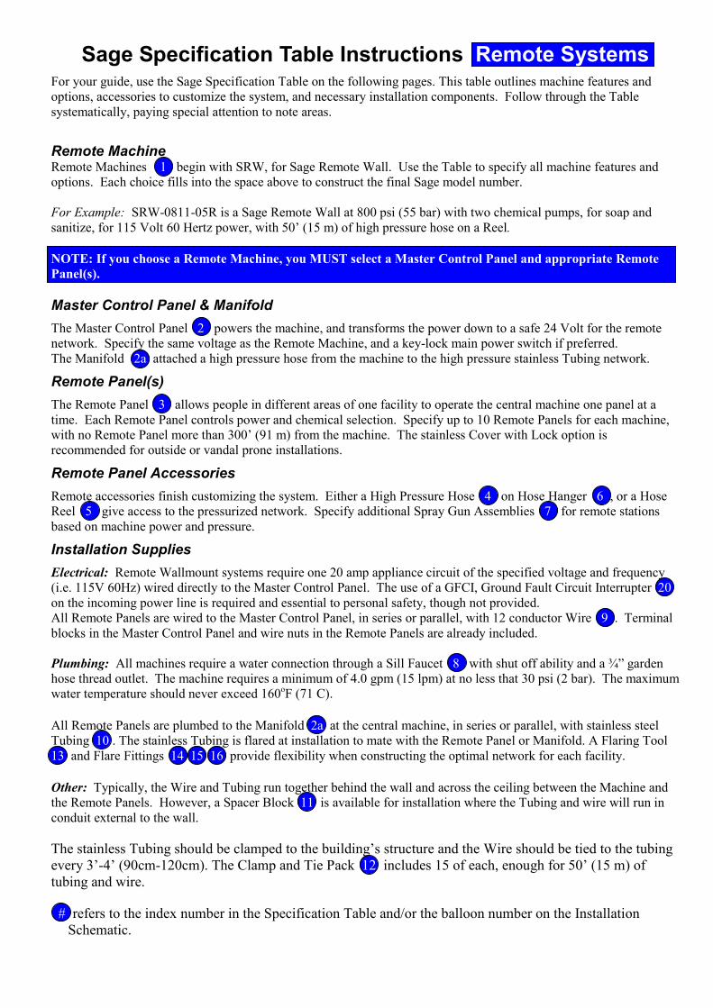
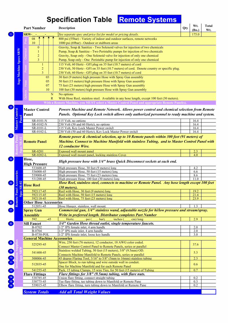
Sage Specification Table Instructions Remote Systems For your guide, use the Sage Specification Table on the following pages. This table outlines machine features and
options, accessories to customize the system, and necessary installation components. Follow through the Table
systematically, paying special attention to note areas.
Remote Machine Remote Machines 1 begin with SRW, for Sage Remote Wall. Use the Table to specify all machine features and
options. Each choice fills into the space above to construct the final Sage model number.
For Example: SRW-0811-05R is a Sage Remote Wall at 800 psi (55 bar) with two chemical pumps, for soap and
sanitize, for 115 Volt 60 Hertz power, with 50’ (15 m) of high pressure hose on a Reel.
NOTE: If you choose a Remote Machine, you MUST select a Master Control Panel and appropriate Remote
Panel(s).
Master Control Panel & Manifold
The Master Control Panel 2 powers the machine, and transforms the power down to a safe 24 Volt for the remote
network. Specify the same voltage as the Remote Machine, and a key-lock main power switch if preferred.
The Manifold 2a attached a high pressure hose from the machine to the high pressure stainless Tubing network.
Remote Panel(s)
The Remote Panel 3 allows people in different areas of one facility to operate the central machine one panel at a
time. Each Remote Panel controls power and chemical selection. Specify up to 10 Remote Panels for each machine,
with no Remote Panel more than 300’ (91 m) from the machine. The stainless Cover with Lock option is
recommended for outside or vandal prone installations.
Remote Panel Accessories
Remote accessories finish customizing the system. Either a High Pressure Hose 4 on Hose Hanger 6 , or a Hose
Reel 5 give access to the pressurized network. Specify additional Spray Gun Assemblies 7 for remote stations
based on machine power and pressure.
Installation Supplies
Electrical: Remote Wallmount systems require one 20 amp appliance circuit of the specified voltage and frequency
(i.e. 115V 60Hz) wired directly to the Master Control Panel. The use of a GFCI, Ground Fault Circuit Interrupter 20
on the incoming power line is required and essential to personal safety, though not provided.
All Remote Panels are wired to the Master Control Panel, in series or parallel, with 12 conductor Wire 9 . Terminal
blocks in the Master Control Panel and wire nuts in the Remote Panels are already included.
Plumbing: All machines require a water connection through a Sill Faucet 8 with shut off ability and a ¾” garden
hose thread outlet. The machine requires a minimum of 4.0 gpm (15 lpm) at no less that 30 psi (2 bar). The maximum
water temperature should never exceed 160oF (71 C).
All Remote Panels are plumbed to the Manifold 2a at the central machine, in series or parallel, with stainless steel
Tubing 10 . The stainless Tubing is flared at installation to mate with the Remote Panel or Manifold. A Flaring Tool
13 and Flare Fittings 14 15 16 provide flexibility when constructing the optimal network for each facility.
Other: Typically, the Wire and Tubing run together behind the wall and across the ceiling between the Machine and
the Remote Panels. However, a Spacer Block 11 is available for installation where the Tubing and wire will run in
conduit external to the wall.
The stainless Tubing should be clamped to the building’s structure and the Wire should be tied to the tubing
every 3’-4’ (90cm-120cm). The Clamp and Tie Pack 12 includes 15 of each, enough for 50’ (15 m) of
tubing and wire.
# refers to the index number in the Specification Table and/or the balloon number on the Installation
Schematic.
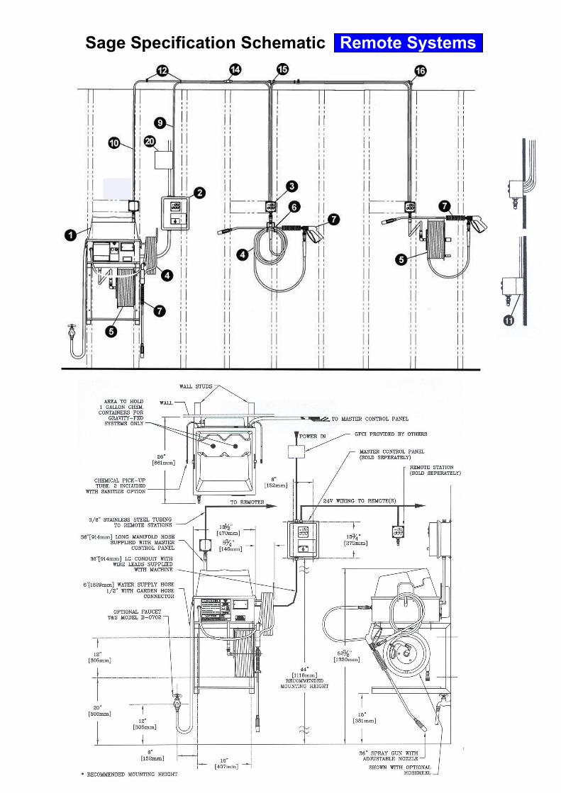
Sage Specification Schematic Remote Systems
Part Number Description QtyWt.
(lbs.)
Total
Wt.
SRW-__-_____-_____ See separate spec and price list for model or pricing details. 175.0
08
10
0
1
2
3
1
2
3
03
05
07
10
N
R
Master Control
Panel
SR-0101-N 115 Volt, no options 16.4 SR-0102-N 230 Volt (50 and 60 Hertz), no options 16.4 SR-0101-L 115 Volt, Key Lock Master Power switch 16.4 SR-0102-L 230 Volt (50 and 60 Hertz), Key Lock Master Power switch 16.4
Remote Panel
SR-0201 Exposed wall mount panel 2.3 SR-0202-L Exposed wall mount panel, locking stainless Cover 4.0
Hose,
High Pressure 533600-45 High pressure Hose, 30 feet (9 meters) long 4.2 536000-45 High pressure Hose, 50 feet (15 meters) long 6.6 539000-45 High pressure Hose, 75 feet (23 meters) long 8.6 531200-45 High pressure Hose, 100 feet (30 meters) long 11.0
Hose Reel
592117-45 Reel with Hose, 30 feet (9 meters) long 19.2 592115-45 Reel with Hose, 50 feet (15 meters) long 21.4 592118-45 Reel with Hose, 75 feet (23 meters) long 23.9
512051-45 Hose Hanger, stainless, wall mount. 1.3
Spray Gun
Assembly 592______-45 ____ Hertz, ______ psi (____ bar), ____ inches (____ cm) long 2.9
Sill Faucet B-0702 1/2" IPS female inlet, 4 arm handle 2.0 B-0704 1/2" IPS male inlet, 4 arm handle 2.0 B-0730-POL 1/2" IPS female inlet, loose key handle 3.0
525295-45Wire, 250 feet (76 meters), 12 conductor, 18 AWG color coded.
Connect Master Control Panel to Remote Panels, series or parallel.37.6
541400-45Stainless welded Tubing, 50 feet (15 meters), 3/8" (9.5mm) OD.
Connects Machine Manifold to Remote Panels, series or parallel.5.3
500006-45 45 degree Flaring Tool, 3/16" to 5/8" (5mm to 16mm) stainless tubing. 2.3
512035-45Spacer Block, to run tubing and wire outside wall in conduit.
One for Machine Manifold and for each Remote Panel.0.6
541255-45 Pack, 15 tubing Clamps, 15 wire Ties, for 50 feet (15 meters) of Tubing. 0.7
Flare Fittings 538785-45 Union flare fitting, connect straight tubing 0.2 538775-45 Tee flare fitting, tee tubing down to Manifold or Remote Panel 0.3 539015-45 Elbow flare fitting, turn tubing down to Manifold or Remote Panel 0.2
System Totals Add all Total Weight Values
Remote power & chemical selection, up to 10 Remote panels within 300 feet (91 meters) of
Machine. Connect to Machine Manifold with stainless Tubing, and to Master Control Panel with
12 conductor Wire.
General Machine Accessories
Other Hose Accessories
800 psi (55bar) - Variety of indoor and outdoor surfaces, remote networks
1000 psi (69bar) - Outdoor or stubborn areas
Gravity, Soap & Sanitize - Two Solenoid valves for injection of two chemicals
Pump, Soap & Sanitize - Two Peristaltic pumps for injection of two chemicals
Gravity, Soap only - One Solenoid valve for injection of only one chemical
Pump, Soap only - One Peristaltic pump for injection of only one chemical
115 Volt, 60 Hertz - GFI plug on 35 feet (10.7 meters) of cord
230 Volt, 50 Hertz - GFI on 35 feet (10.7 meters) of cord. Denote country or specific plug.
230 Volt, 60 Hertz - GFI plug on 35 feet (10.7 meters) of cordGFI = Ground Fault Interrupter
Powers Machine and Remote Network. Allows power control and chemical selection from Remote
Panels. Optional Key Lock switch allows only authorized personnel to ready machine and system.
With a Remote Machine, you MUST select a Master Control Panel and appropriate Remote Panel(s).
Sage Machine Specs SRW
Master Control
Panel
30 feet (9 meters) high pressure Hose with Spray Gun assembly
50 feet (15 meters) high pressure Hose with Spray Gun assembly
75 feet (23 meters) high pressure Hose with Spray Gun assembly
100 feet (30 meters) high pressure Hose with Spray Gun assembly
Specification Table Installation Supplies
Spec SRW
3/4" Garden Hose thread outlet, single temperature faucets.
Remote Panel Accessories
Spec SR-02
Remote Panel
Spec SR-02
Flare fittings for 3/8" (9.5mm) tubing, with flare nuts.
Commercial gun, 1/4" stainless wand, adjustable nozzle for hi/low pressure and stream/spray.
Write in preferred length. Distributor completes Part Number
No options
With Hose Reel, stainless steel. Available in any hose length, except 100 feet (30 meters).
Hose Reel, stainless steel, connects to machine or Remote Panel. Any hose length except 100 feet
(30 meters).
High pressure hose with 1/4" brass Quick Disconnect sockets at each end.
Remote Systems
1
Pres.
Chemical
Power
Hose
Options
2
3
4
5
6
7
8
9
10
0
11
12
13
14
15
16

Part Number Description QtyWt.
(lbs.)
Total
Wt.
S__-_______-_______ See separate spec and price list for model or pricing details. 175.0
M M - Mobile mount, on a stainless steel cart with commercial castors
W W - Wall mount, on a stainless steel wall bracket
06 600 psi (41bar) - Indoor use, sensitive flooring, walls, equipment
08
10
0
1
2
3
1
2
3
03
05
07
10
N
R
Sill Faucet
B-0702 1/2" IPS femail inlet, 4 arm handle 2.0 B-0704 1/2" IPS mail inlet, 4 arm handle 2.0 B-0730-POL 1/2" IPS femail inlet, loose key handle 3.0
512051-45 Hose Hanger, stainless, wall mount. 2.3
System Totals Add all Total Weight Values
Sage Specification Table Instructions
Stand-alone Machines 1 begin with SW for Sage Wall on a bracket, or SM for Sage Mobile on a cart. First, use the
table to choose machine mount. Second, select all features and options. Each choice fills into the space above to
construct the final Sage model number.
Electrical: Stand-alone Wallmount and Mobile systems require one 20 amp appliance circuit of the specified voltage
and frequency with a standard receptacle for the chosen power. Sage Systems supplies a GFCI 20 with stand-alone
systems on the Machines power cord.
Plumbing: All machines require a water connection through a Sill Faucet 8 with shut off ability and a ¾” garden hose
thread outlet. The Machine requires a minimum of 4.0 gpm (15 lpm) at no less that 30 psi (2 bar). Maximum water
temperature should never exceed 160oF (71 C).
3/4" Garden Hose thread outlet, single temperature faucets.
Sage Machine Specs SW, SM
Installation Supplies
Spec SM, SW
30 feet (9 meters) high pressure Hose with Spray Gun assembly
50 feet (15 meters) high pressure Hose with Spray Gun assembly
75 feet (23 meters) high pressure Hose with Spray Gun assembly
100 feet (30 meters) high pressure Hose with Spray Gun assembly
Other Hose Accessories
Specification Table
No options
With Hose Reel, stainless steel. Available in any hose length, except 100 feet (30 meters).
800 psi (55bar) - Variety of indoor and outdoor surfaces, remote networks
1000 psi (69bar) - Outdoor or stubborn areas
Gravity, Soap & Sanitize - Two Solenoid valves for injection of two chemicals
Pump, Soap & Sanitize - Two Peristaltic pumps for injection of two chemicals
Gravity, Soap only - One Solenoid valve for injection of only one chemical
Pump, Soap only - One Peristaltic pump for injection of only one chemical
115 Volt, 60 Hertz - GFI plug on 35 feet (10.7 meters) of cord
230 Volt, 50 Hertz - GFI on 35 feet (10.7 meters) of cord. Denote country or specific plug.
230 Volt, 60 Hertz - GFI plug on 35 feet (10.7 meters) of cordGFI = Ground Fault Interrupter
1
Pres.
Chemical
Power
Hose
Options
8
9
Mt.
8
8
Stand-alone Machines
1
8
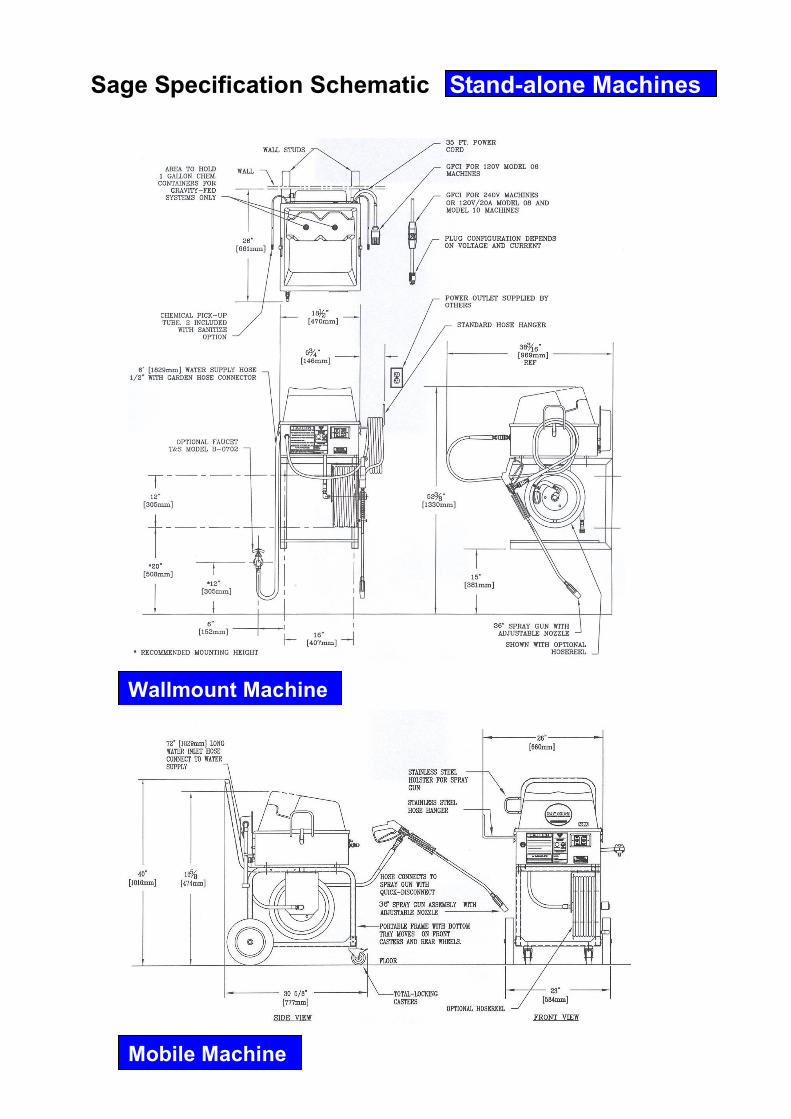
Sage Specification Schematic Stand-alone Machines
Wallmount Machine
Mobile Machine
The quality behind the system
Mobile Wall Mounted Central Systems
The quality behind the system
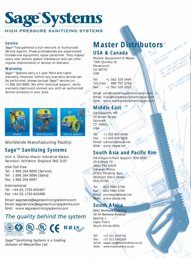
ServiceSageTM has gathered a full network of AuthorizedService Agents. These professionals are experiencedfoodservice equipment repair personnel. They inspectevery new remote system installation and can offerregular maintenance or service on demand.
WarrantySageTM Systems carry a 1 year Parts and Laborwarranty. However, before any warranty service canbe performed, please contact SageTM service on: +1 866 264 8895. We offer technical support, verifywarranty claims and connect you with an authorizedservice company in your area.
Mobile Wall Mounted Central Systems
SageTM Sanitizing Systems Unit 4, Cheney Manor Industrial Estate,Swindon, Wiltshire, England SN2 2UD
USA Toll FreeTel: 1 866 264 8895 (Service)Tel: 1 866 264 8896 (Sales)Fax: 1 866 264 8897
InternationalTel: +44 (0) 1793 603487Fax: +44 (0) 1793 603489
Email: [email protected]: [email protected]: www.sagesanitizingsystems.com
Master DistributorsUSA & Canada Market Equipment & Repair7300 Quimby St.ParamountCA 90723USA
Tel: +1 562 529 5494Toll free: 888 757 3784Fax: +1 562 529 5310
Email: [email protected]: [email protected]: www.marketequipmentrepair.com
Middle East D&S Exports, Inc24 Broad StreetNorwalkCT 06851USA
Tel: +1 203 847 6446Fax: +1 203 849 9526Email: [email protected]: www.dsusa.net
South Asia and Pacific RimD&S Exports Pure Support SDN BHD29-6 Block F2Jalan PJU 1/42ADataran Prima47301 Petaling JayaSelangor Darul EhsanMALAYSIA
Tel: 603 7880 5758Fax: 603 7880 5760Email: [email protected]: www.dsusa.net
South AfricaMAC Brothers Catering32-34 Benbow AvenueEpping 1Cape TownSouth Africa 8001
Tel: +27 021 5054100Fax: +27 021 5340319Email: [email protected]: www.macbrothers.co.za
Worldwide Manufacturing Facility:
SageTM Sanitizing Systems is a trading division of Mecserflex Ltd.
One Spray Gun Assembly included with system
230 Volt Pump Feed machines use Diaphragmpump(s) instead of Peristaltic pump(s).
Model: SM -08- 0 1 - 05 R
06
08
10
0
1
2
3
1
2
3
03
05
07
10
N
R
SM
SW
SRW
POWER1 = 115 Volt, 60 Hertz2 = 230 Volt, 50 Hertz3 = 230 Volt, 60 Hertz
HOSE LENGTH03 = 30 feet (9.1 meters)05 = 50 feet (15.2 meters)07 = 75 feet (22.9 meters)10 = 100 feet (30.5 meters)
OPTIONSN = No other optionsR = Stainless Manual Hose Reel(up to 75’ (22.9 m) of hose)
PRESSURE06 = 600 PSI (41 bar) max.08 = 800 PSI (55 bar) max.10 = 1000 PSI (69 bar) max.
MODELSM = Mobile.SW = Wall Mounted.SRW = Central System with Remote Stations
CHEMICAL INJECTION0 = Soap & Sanitize, Gravity Feed1 = Soap & Sanitize, Pump Feed2 = Soap only, Gravity Feed3 = Soap only, Pump Feed
Technical Specification Order Codes
Master Control Panel and Remote Panel Specifications
Example ShownMobile unit - 800 PSI with Gravity feed soap & Sanitize Injection, 115 Volt
60 HZ - including 50’ Hose on a manual hose reel.
NOTE: If you choose a Remote Machine, you MUST select a Master Control Panel and appropriate Remote Panel(s)and optional accessories.
01 N02 L
OPTIONSN = No other optionsL = Master switch with lock key
0102L
DESIGN1 = Exposed Remote2 = Exposed Remote with
Locking Security Cover
Master Control Panel Specifications Remote Panel Specifications
Model: SR-01 _ - _ Model: SR-02 _
www.sagesanitizingsystems.com
Overview
Example
POWER1 = 115 Volt, 60 Hertz2 = 230 Volt, 50/60 Hertz
Sage6ppBro:Sage 23/4/07 17:54 Page 1