The intelligent alternative for VA meters: mass flow meters for gases ...

Make the Wise Choice. Choose Sage Flow Meters.
SAGE GAS MASS FLOW METERS FOR INDUSTRIAL & ENVIRONMENTAL APPLICATIONS
SAGE GAS MASS FLOW METERSFOR INDUSTRIAL & ENVIRONMENTAL APPLICATIONS

DEDICATIONSage Metering is your source for monitoring, measuring and controlling the gas mass flow in your
industrial process, building management system or environmental application. Our high performance,
NIST Traceable,Thermal Mass Flow Meters will help increase productivity, reduce energy costs, maximize
product yields, and/ or help reduce environmental insult. Sage provides high quality In-Line and
Insertion Thermal Mass Flow Meters for a wide variety of industrial, commercial, and environmental
monitoring needs, including carbon credit verification for Greenhouse Gas reduction.
Our experienced application engineers, many of whom have worked in the Thermal Mass Flow marketplace
since its inception, will assist you in choosing the proper gas flow meter for your application – and they will be pleased to offer installa-
tion guidance to assure that the meter(s) selected will perform as accurately as possible. Additionally, our Service Staff stand ready to
support you with any after-sale assistance that you may require.
Q U A L I T Y P E R F O R M A N C E
S U P P O R T
M A S S
F L O W
{ 2 } S A G E M E T E R I N G , I N C .
HOW DOES THERMAL MASS FLOW MEASUREMENT BENEFIT YOU?
n Direct Mass Flow – No need for separate temperature or pressure transmitters
n High Accuracy and Repeatability – Precision measurement and optimal control
of your process
n Turndown of 100 to 1 and resolution as much as 1000 to 1
n Low-End Sensitivity – Detects leaks, and measures as low as 5 SFPM!
n Negligible Pressure Drop – Will not impede the flow or waste energy
n No Moving Parts – Eliminates costly bearing replacements, and prevents
undetected accuracy shifts
n Dirt Insensitive – Provides sustained performance
n Low cost of ownership
n Ease of installation and convenient mounting hardware
WHAT ARE THE BENEFITS THAT SAGE THERMALMASS FLOW METERS OFFER YOU?
n Powerful state-of-the-art microprocessor technology designed for high performance
mass flow measurement, at a low cost-of-ownership
n Rugged, user-friendly packaging with easy terminal access [SIP/SRP]
n Proprietary digital sensor drive circuit provides enhanced signal stability and
is unaffected by process temperature and pressure changes
n Low power dissipation, under 2.5 Watts (e.g. under 100 ma at 24 VDC) [SIP/SRP]
n High contrast photo-emissive OLED display with numerical Flow Rate,Total and
Temperature, as well as Graphical Flow Indicator [SIP/SRP]
n Displays calibration milliwatts (mw) for ongoing diagnostics [SIP/SRP]
n Remote Style has Lead-Length Compensation. Allows remote electronics up to
1000 ft from probe; Explosion Proof Junction Box has no circuitry, just terminals
n Modbus® compliant RS485 RTU communications [SIP/SRP]
n Flow conditioning built into In-Line flow meters (1/2" and up)
n Option for Solar Energy use (12VDC models) [SIP/SRP]
n Field reconfigurability via keypad [SIG/SRG/SIE/SRE]
n Field reconfigurability via Sage VIP [SIG/SRG/SIE/SRE]
n Field reconfigurability via Sage ADDRESSER or Sage Dongle [SIP/SRP]
n Multiple channels (up to four different calibrations in one meter) [SIG/SRG/SIE/SRE]
n Captive Flow Conditioners for Insertion Meter applications
SIP–Integral Prime (Insertion Style shown)
SRG–Remote General Purpose (Insertion Style shown)
SIE–Integral Explosion Proof (In-Line Style – shown with optional Flanges)

S A G E M E T E R I N G , I N C . { 3 }
Our award winning technology has many unique
features, such as the ability to provide four totally
independent calibrations or ranges in one meter,
and the proprietary sensor circuitry provides extra-
ordinary temperature compensation (even from
large process temperature variations in excess of
200 degrees F). Furthermore, we can easily resolve
velocities as low as 5 SFPM (i.e., less than 1/2 SCFM
in a 4" pipe), or as high as 35,000 SFPM (over 3,000
SCFM in a 4" pipe). On most product configurations,
our display is back-lit, and the menu items on the
keypad (or via the laptop) are extremely easy to
access.We also have a convenient “Sensor Function-
ality and Zero Calibration Self-Check” that is acces-
sible via the Sage Prime display, or via the Keypad
or navigational software on our other products. This
diagnostic procedure features a calibration routine
that not only checks the sensor performance and
the "live zero" calibration point, but it also verifies
that the sensor is clean. It essentially provides a
means to validate the meter’s performance, veri-
fies that there is no shift or drift, and eliminates
the need for annual factory calibrations.
Our most popular thermal mass flow meter config-
uration is our Remote Series. In this configuration,
the Probe or the Flow Body Junction Box is Explosion
Proof and it has no electronics, and thus is suitable
for harsh environments (very hot or very cold am-
bient temperatures, or even vibrating pipes). A 6-
conductor shielded interconnect cable (25 feet ini-
tially supplied) connects to the Remote Electronics
Enclosure (Explosion Proof) which has a lead-length
compensated circuit.The circuit compensates for
cable lengths up to 1000 feet in length (10 ohms
max loop resistance) without affecting the meter’s
accuracy or performance.The Remote Enclosure
(whether mounted in a Control Room, or simply
placed at eye-level near the process), is the heart
of the instrument, and has a display of Flow Rate,
Total and Temperature, as well as a 4-20 ma output
of Flow Rate. Most products also have a 4-20mA
output of Temperature. Pulsed outputs of Totalized
Flow are also available.The electronics can be pow-
ered by 24 VDC or 115 VAC/230 VAC (Prime also has
12VDC option for Solar Power).
PRIME EXPLOSION PROOF GENERAL PURPOSE “LITE” (No Display)
SIP Series SIE Series SIG Series SIL Series
IN-LINE INSERTION IN-LINE INSERTION IN-LINE INSERTION IN-LINE INSERTION
PRIME EXPLOSION PROOF GENERAL PURPOSE “LITE” (No Display)
SRP** Series SRE** Series SRG Series SRL Series
IN-LINE INSERTION IN-LINE INSERTION IN-LINE INSERTION IN-LINE INSERTION
*All four categories (Series) have Explosion Proof Junction Boxes
(the enclosure at the probe or flow body)
**Remote Mounting Hardware is provided with these models
VERSATILITYSage Metering manufactures award-winning Insertion and In-Line Thermal Mass Flow Meters for a variety of industrial,
commercial, environmental, and municipal applications. Our high performance, NIST traceable Thermal Mass Flow Meters will
help you increase productivity, reduce energy costs, and maximize product yields. A variety of configurations are available to
help you monitor the flow rate and measure the consumption of various common gases such as natural gas, propane, digester
gas, landfill gas, mixed gases, hydrogen, nitrogen, carbon dioxide, exhaust air, combustion air, and compressed air. Consider the
popular Remote Flow Meter configuration, featuring an Explosion Proof Junction Box with convenient mounting terminals,
ideal for any challenging environmental conditions (extreme heat, cold or vibration).The Remote Style Flow Meters are sup-
plied with 25 feet of cable (other lengths optional) and feature a lead-length compensated circuit.This unique circuitry per-
mits the cable to be shortened or lengthened in the field (up to 1000 feet) with out any loss in meter accuracy.
Flow Control Magazine
2006 Innovations Awards
W I N N E R
I N T E G R A L F L O W M E T E R S
R E M O T E F L O W M E T E R S *

optional, or 115/230 VAC).The power dissipation is
under 2.5 watts (e.g. under 100 ma at 24 VDC).
It has a 4-20 ma output as well as a Pulsed Out-
put of Totalized Flow (solid state [sourcing] tran-
sistor drive). In addition, Sage Prime supports full
Modbus® compliant RS485 RTU communications
(IEEE 32 Bit Floating Point). See page 6 for addi-
tional information.
FEATURES AND BENEFITS OF
EXPLOSION PROOF (SIE/SRE) SERIES
The innovative Sage design features an easy-to-use
menuing system, a mass flow, total and
temperature display, and convenient
4-button Keypad to integrate the
functions of flow measurement
with your specific needs.You will
have the flexibility to use the local
display/Keypad, or a computer,
to change configurations or
to conduct basic diagnostics,
including a calibration self-check with a sim-
ple routine using the Keypad, or with the Sage
Navigational Software (Sage VIP). At any time
you can use the user-friendly menuing system to
change full scale values, digitally filter the flow
signal, change decimal points, set zero cutoffs,
check diagnostics, or reconfigure an insertion
meter for a different pipe size. In addition, you
can order your meter configured for up to four
different gas calibrations, and simply select the
desired channel (A-D) at any time (e.g. four dif-
ferent gases, sensitivities, or configura-
tions). Or you can order the meter cali-
brated for one gas (e.g. compressed air),
but have it pre-configured for up to four different
pipe sizes and full scales, so you can simply select
the desired channel (A-D) based on the application.
Channels are totally independent and each have
their own full scale accuracy statement and set-
tings.The SIE/SRE Explosion Proof Series has one
4-20 mA output of Flow Rate, and it has one relay
that can be configured for pulsed output of
Totalized Flow (or configured for other functions,
if desired). It also has RS232 communications.The
relay can be configured by computer using VIP soft-
ware for a variety of settings, including trip-high,
trip-low (with or without delays),window alarms,
pulsed outputs, timer outputs, etc.
FEATURES AND BENEFITS OF
GENERAL PURPOSE (SIG/SRG) SERIES
The SIG/SRG Series has similar features to the above
mentioned SIE/SRE Series, except it has a large for-
mat Touch Screen display of mass flow, total and
temperature. It too has an easy-to-use 4-button
Keypad for viewing Menus or reconfigurability.
In addition, it has two 4-20 mA outputs, one
for Flow Rate as well as one for Temperature.Two
independent, 1 amp SPDT dry contact relays are
standard on the SIG and SRG Series.They can be
configured by the
computer using
VIP Software
for a variety
of settings,
including trip-
high, trip-low
(with or without
delays), window
alarms, pulsed
outputs, timer
outputs, etc.
FEATURES AND BENEFITS
OF SAGE LITE (SIL/SRL) SERIES
“Sage Lite” has many features of the standard
product line, but does not have a display, does
not have a menuing Keypad, does not support
multiple channels, and does not support relay
outputs. However it has linear outputs of flow
rate and temperature, or is optionally configurable
to have one output that provides pulsed outputs
of totalized flow. It is offered in a 5x5x4 NEMA 4X
enclosure, or optional Explosion Proof Enclosure,
or as a small circuit assembly for customized end-
user packaging (OEM’s).
CONTACT SAGE FOR
APPLICATION ASSISTANCE
If there are any features that you require on any
of these products, or if you need application assis-
tance, feel free to contact our local factory trained
Representative in your area.Visit us online at
www.sagemetering.com, or phone the Sage Sales
or Service Staff for assistance at 866-677-7243,
our toll-free number.
BENEFITSHIGH PERFORMANCE FEATURES
Sage Thermal Mass Flow Meters are designed for
high performance mass flow measurement of flow
rate and consumption of gases such as natural gas,
air, oxygen, digester gas, landfill gas, biogas, gas
mixes, flare gas, nitrogen, carbon dioxide, oxygen
and hydrogen.
Sage Metering has distinguished itself by offering
a higher standard – our mass flow meter output is
unaffected by even large process temperature varia-
tions, and our digital electronics is impervious to
external analog noise. Fast response, high resolu-
tion, and ultra sensitivity are features
that are at the heart of every Sage
Thermal Mass Flow Meter.
All Sage meters, depending on
product style, can be reconfigured
in the field (contact Sage for
details concerning software and
related accessories). In addition,
all meters have a convenient in-situ
field diagnostic procedure that verifies that the
original factory calibration hasn’t drifted, shifted,
or changed.This “Sensor Functionality and Zero
Self Check” also verifies that the sensor is free
from contamination, even without inspection.
All Sage Flow Meters are offered in the Integral
Style or Remote Style (with lead-length compensa-
tion up to 1000 feet) with explosion proof Junction
Box with your choice of Probe or Flow Body
depending on your pipe size.
FEATURES AND BENEFITS OF
PRIME (SIP/SRP) SERIES
Sage Prime is the latest addition to our
family of high performance Thermal Mass Flow
Meters. It features a bright new graphical display of
Flow Rate, Total and Temperature, robust industrial
enclosure, and easy to access power and output
terminals. Sage Prime has a dual-compartment
windowed enclosure featuring a very high contrast
photo-emissive OLED display.
The rear compartment,
which is separated from
the electronics, has large,
easy-to-access and well
marked terminals, for
ease of customer wiring. It is
powered by 24 VDC (12 VDC
SAGE THERMAL MASS FLOW METERS
SIG Series Integral General Purpose Mass
Flow Meter (In-Line Style shown)
SIP Series Integral Prime
Mass Flow Meter
(Insertion Style shown)
{ 4 } S A G E M E T E R I N G , I N C .

GENERAL SPECIFICATIONS FOR SAGE MASS FLOW METERS
PERFORMANCE
n Accuracy: +/- 0.5% of Full Scale +/- 1% of reading with
a turn-down of 100 to 1 and resolution as much as 1000
to 1 (special accuracy with less turn-down, upon request)
n Repeatability: 0.2%
n Calibration: Sage Metering’s NIST calibration facility
(National Institute of Standards Traceable)
n Gas Temperature3: Std.: -40°F to 200°F (-40°C to 93°C);
HTO1: 200°F to 300°F (93°C to 149°C ); HTO2: 300˚F to
450˚F (149˚C to 232˚C); HTO3: 450˚F to 750˚F (232˚C to
399˚C)
n Standard Calibration Reference Conditions: 70˚F and
29.92" Hg (other Reference Conditions can be specified)
n Integral or Remote Enclosure Temperature:
0° to 150°F (-18°C to 65°C ). Contact Sage for lower
temperature ranges Note: Remote Enclosure can be
mounted up to 1000 feet away from sensor and its
Junction Box in order to be located in a suitable tem-
perature environment
n Pressure Rating: 500 psig (1000 psig optional)
n Response Time: 1 second (each time constant) for
flow change
FLOW RANGE / SIZES
n Units of Measurement: Flow–SCFS, SCFM, SCFH,
SCFD1, SCCM, NCMM, NCMH, KG/S, KG/M, KG/H, KG/D1,
LBS/S, LBS/M, LBS/H, LBS/D1, SLPM, SLPH; Velocity–
SFPS, SFPM, NMPS, NMPM, NMPH (other combinations
available); Temperature –°C and °F
n Insertion Meters: Full Scale up to 35,000 SFPM (i.e.,
up to 12,000 SCFM in an 8" Sch. 40 Pipe). Higher veloci-
ties optionally available. Resolve as low as 5 SFPM5
GENERAL
n Relays: Two 1-amp relay channels (each SPDT) on
SIG & SRG Series. One 1-amp relay on SIE & SRE Series.
Menu configurable (see description under Features &
Benefits on page 4)
n Sensor Drive Circuit: Proprietary Sensor Drive Circuit
provides enhanced flow signal stability and insensitivity
to process temperature changes2
n Multiple Channel Capability: Up to four totally inde-
pendent calibrations available on SIG & SRG Series as
well as SIE & SRE Series (for SIP & SRP Series, only feasi-
ble with Dongles4). Calibrate for four different gases,
different sensitivities, and/or different configurations
(Channels A–D). Channels can be keypad, computer or
externally selectable (via contact closures)
WETTED PARTS
316L Stainless Steel for Flow Bodies, Sensor Flow
Elements and Flow Conditioners. Hastelloy (recommend-
ed for Chlorine Gas) and other materials optional
FLOW CONDITIONING
All In-Line Style Flow Meters 1/2 inch and above include
built-in flow conditioning. For Insertion Style Flow
Meters, Captive Flow Conditions are optional.
ETHERNET COMPATIBILITY OR WIRELESS MODBUS
Contact Sage for information.
LIMITED WARRANTY
Sage Metering’s Series of Thermal Mass Flow Meters are
warranted against faulty materials or workmanship for
one year from the date of delivery to the buyer. After
issuance of a Return Meter Authorization (RMA) by Sage,
and upon receipt of the defective meter, Sage will either
repair or replace the defective meter at its sole option
and at no cost to the purchaser
GENERAL TERMS AND CONDITIONS
See "General Terms" link on the Footer of the Homepage
of Sage website (www.sagemetering.com)
differential be maintained, even if there are wide
fluctuations in gas temperature. It is the “job” of the
Sage proprietary sensor drive circuit to maintain the
differential, whether or not the gas temperature
changes, or however quickly the flow of molecules
cools off the flow sensor. It is also necessary to prop-
erly calibrate the meter with the actual gas (or close
equivalent with certain gases), in the Sage NIST
certified calibration facility (National Institute of
Standards). By accomplishing these two critical
objectives, the Sage Flow Meters provide an
extremely repeatable (0.2% of full scale) and
accurate output directly proportional to the mass
flow rate of the gas being measured.
S A G E M E T E R I N G , I N C . { 5 }
1 Not available on Prime (SIP/SRP)
2 Circuit will compensate for gradual temperature process changes over a very wide range. See Gas Temperature
3 HTO1, HTO2, HTO3 options apply to Remote Insertion Meters only
4 For SIP & SRP, each Dongle represents a different Channel. Upload the desired Dongle on the Modbus terminals
5 See “Minimum Resolution in SLPM” on table on page 10 (column is based on velocity of 5 SFPM)
SERVICEPRINCIPLE OF OPERATION OF
THE THERMAL MASS FLOW METER
Sage Thermal Mass Flow Meters have two sensors
constructed of reference grade platinum windings
(RTDs).The two RTDs are clad in a protective 316SS
sheath and are driven by a proprietary sensor drive
circuit. One sensor is self-heated (flow sensor), and
the other (temperature/reference sensor) measures
gas temperature.The pair is referred to as the
sensing element, and is either installed in a probe
as an Insertion Style, or inserted into a pipe section
as an In-Line Style flow meter. As gas flows by the
flow sensor, the gas molecules carry heat away
from the surface, and the sensor cools down as it
loses energy.The sensor drive circuit replenishes
the lost energy by heating the flow sensor until it
is a constant temperature differential above the
reference sensor.
The electrical power required to maintain a con-
stant temperature differential is directly propor-
tional to the gas mass flow rate and is linearized to
be the output signal of the meter.
It is essential that this constant temperature
PLEASE NOTE
Performance specifications are effective with date of issue and are
subject to change without prior notice.The metering devices and
other equipment pictured in this brochure are for identification and
illustration purposes only.The appearance and dimensions of the
actual products may differ slightly from those shown but will perform
as represented. Sage Metering, Inc. reserves the right, at any time, to
make such modifications and changes to the products shown herein
as it deems appropriate, without prior notice to the customer.

QUALITYSage Prime™ is a thermal dispersion type of Flow
Meter, utilizing the constant temperature differ-
ence method of measuring Gas Mass Flow Rate.
It contains two reference grade platinum RTD
sensors clad in a protective 316 SS sheath. It fea-
tures direct Mass Flow for gases, wide rangeability,
low pressure drop, very low end sensitivity, and no
moving parts.
The Prime is microprocessor based, does not have
any potentiometers, and has Modbus® RS485 RTU
communications. It is powered by 24 VDC (12 VDC
optional, or 115/230 VAC).The power dissipation is
under 2.5 watts (e.g. under 100 ma at 24 VDC for
the DC version).The power and output terminals
are in a separate compartment for ease of install-
ation. Sage Prime is CSA, UL, and ATEX approved
for the 24VDC powered version and CE
approved on all models, and Medically
CE approved for AC models (consult web-
site, and select “Approvals” tab for most
recent approvals).
The enclosure has a dual compartment
for ease of wiring.The display is a high
contrast photo-emissive OLED display, and
it displays Mass Flow Rate, Totalized Flow
and Temperature as well as a graphical
representation of Flow Rate in a horizontal
bar graph format. In addition, the calibra-
tion milliwatts (mw) is continuously
displayed, providing ongoing diagnostics.
Outputs include a 4-20 ma signal propor-
tional to Mass Flow Rate, and Pulsed
Outputs of Totalized Flow (12VDC solid
state [sourcing] transistor drive), as well as
Modbus® compliant RS485 RTU communi-
cations (IEEE 32 Bit Floating Point).
SAGE PRIME MASS FLOW METER
Remote
Mounting
Hardware
(included)
SAGE PRIME FEATURESn Sage Prime is our latest addition to our family
of high performance Thermal Mass Flow Meters,
and is priced very attractively
n It features a bright new, high contrast, photo-
emissive OLED display of Flow Rate, Total and
Temperature in a robust, yet lightweight, dual
compartment heavy duty enclosure.The flow
rate is also displayed graphically in a horizontal
bar graph format
n In addition, calibration milliwatts (mw) is contin-
uously displayed providing ongoing diagnostics
n The rear compartment, is completely separated
from the electronics, and has large, easy-to-
access, well marked terminals, for ease of
Optional Programmable Dongle
customer wiring (no longer does the user need
to enter near any of the meter's circuitry during
their installation)
n Available outputs include MODBUS (IEEE 32 Bit
Floating Point), 4-20 ma of flow rate and pulsed
outputs of totalized flow
n Powered by 24 VDC (12 VDC optional), with
current dissipation of less than 100 ma, or
115 VAC/230 VAC
n Portable Rechargeable Battery Powered version
(contact Sage)
n Offered in Integral or Remote Style (which
has lead-length compensation up to 1000 feet
as well as an Explosion Proof Junction Box).
Specify any standard probe length or flow
body size
n To simplify installation, all Sage Insertion
Meters will be set up to simply go into
the center of the pipe (refer to Sage Probe
Insertion Guidelines in the Manuals)
n We use the same proven award winning
digital technology to drive the sensor as
our other products, so the accuracy,
repeatability, temperature compensation
and extraordinary low-end sensitivity
have not been compromised in Sage Prime
n With Sage Prime, we keep it simple.
Specify the gas flow rate, pipe size and
units of measurement, and Prime will
arrive configured as requested
n Sage Prime is CE approved, and CSA, UL
and Atex approved for Hazardous Service
(see Approvals tab on the website)
n Sage Prime can be reconfigured in the
field with the Sage Prime ADDRESSER
Software or the Sage Dongle
{ 6 } S A G E M E T E R I N G , I N C .
SIP Series Integral Prime Mass Flow Meter Insertion Style
S I P S E R I E S – I N T E G R A L S R P S E R I E S – R E M O T E

SPECIFICATIONS
EXPLOSION PROOF SIE/SRE
S A G E M E T E R I N G , I N C . { 7 }
Flow Element is In-Line Style consisting of a choice of
316 Stainless Steel Schedule 40 Flow Bodies sized from
1⁄4"x 6" long to 4" x 12" long.
Flow Element is Insertion Style, consisting of a 1⁄2" OD
probe (3⁄4" optional) with lengths up to 36" long
(typically 15" long) suitable for insertion into the cen-
ter of a process pipe.
Flow Element is In-Line Style consisting of a choice of
316 Stainless Steel Schedule 40 Flow Bodies sized from
1⁄4" x 6" long to 4" x 12" long.
Flow Element is Insertion Style, consisting of a 1/2" OD
probe (3⁄4" optional) with lengths up to 36" long
(typically 15" long) suitable for insertion into the cen-
ter of a process pipe.
Flow Meter is thermal dispersion type, utilizing constant temperature difference method of meas-
uring Gas Mass Flow Rate. It contains two reference grade platinum RTD sensors clad in a protective
316 SS sheath. Features direct Mass Flow for gases, wide rangeability, low pressure drop, very low
end sensitivity, and no moving parts.
Flow Meter is microprocessor based, does not have any potentiometers, and has RS232 commu-
nications with accompanying menu driven software (Sage VIP). Flow Meter is powered by 24 VDC
or 115 VAC/ 230 VAC.The power dissipation is under 6 watts (e.g. under 250 ma at 24 VDC).
Calibration Self Check: Flow Meter has built in diagnostics – the menuing system has provisions
to check the sensor’s operation by accessing the sensor’s output, and comparing it to the original
reported “zero flow” value noted on meter’s Certificate of Conformance (last few lines).
Accuracy is +/- 0.5% of Full Scale +/- 1% of Reading with a turn-down of 100 to 1 and resolu-
tion as much as 1000 to 1. Repeatability is 0.2%.The Flow Meter is Sage Metering, Inc. SIE Series.
The electronics has a 4 to 20 ma output proportional to Mass Flow Rate or the output can be fac-
tory or field configured to Temperature. Output is opto-isolated. In addition, one dry contact relay is
provided that can be configured for pulsed outputs of Totalized Flow, or Trip High,Trip Low, and
other functions.
In the Remote Style the electronics is remote with Explosion Proof, Class 1, Div 1, Groups B, C, D, NEMA 4X windowed enclosure, display
and Keypad.The display is a back-lit LCD with two lines of information: Mass Flow Rate on top line; and Totalized Flow and Temperature
on bottom line.The Keypad has 4-buttons and provides a convenient means to interface with an extensive menuing system. Includes
Remote Mounting Hardware.
The Flow Element’s Junction Box is Explosion Proof (Class 1, Div 1, Groups B, C, D), and does not have any electronics – only a wiring
terminal block.The Junction Box is connected to the Remote Electronics by 25 feet of lead-length compensated cable.The cable
(6-conductor) can be lengthened or shortened without affecting accuracy (max loop resistance 10 ohms, up to 1000 feet).
INTEGRAL STYLE ELECTRONICS REMOTE STYLE ELECTRONICS
Electronics is Integral Style, with Explosion Proof, Class 1, Div 1,
Groups B, C, D, NEMA 4X windowed enclosure, local display and
Keypad.The display is a back-lit LCD with two lines of information:
Mass Flow Rate on top line; and Totalized Flow and Temperature
on bottom line.The Keypad has 4-buttons and provides a conven-
ient means to interface with an extensive menuing system.
SIE In-Line1 SIE Insertion2 SRE In-Line1 SRE Insertion2
PRIME SIP/SRPFlow Meter is thermal dispersion type, utilizing constant temperature difference method of measur-
ing Gas Mass Flow Rate. It contains two reference grade platinum RTD sensors clad in a protective
316 SS sheath. Features direct Mass Flow for gases, wide rangeability, low pressure drop, very low
end sensitivity, and no moving parts.
Flow Meter is microprocessor based, does not have any potentiometers, and has Modbus™ RS485
communication. Flow Meter is powered by 24 VDC (12 VDC optional or 115/230 VAC).The power
dissipation is under 2.5 watts (e.g. under 100 ma at 24 VDC). Power and output terminals are in a
separate compartment for ease of installation.
Calibration Self Check: Flow Meter has built in diagnostics – a display of the calibration milli-
watts (mw) can be used to check the sensor’s operation by being compared to the original reported
“zero flow” value noted on meter’s Certificate of Conformance (last few lines) and metallic tag.
Accuracy is +/– 0.5% of Full Scale +/– 1% of reading with a turn-down of 100 to 1 and resolu-
tion as much as 1000 to 1. Repeatability is 0.2%.The Flow Meter is Sage Metering, Inc. SIP Series,
with the trade name Sage Prime™.
The electronics has a 4 to 20 ma output (ground based) proportional to Mass Flow Rate as well as
pulsed outputs of Totalized Flow (12 VDC solid state transistor drive).
Flow Element is In-Line Style consisting of a choice of
316 Stainless Steel Schedule 40 Flow Bodies sized
from 1/4” x 6” long to 4” x 12” long.
Flow Element is Insertion Style, consisting of a 1/2” OD
probe (3/4” optional) with lengths up to 36” long (typ-
ically 15” long) suitable for insertion into the center of
a process pipe.
Flow Element is In-Line Style consisting of a choice of
316 Stainless Steel Schedule 40 Flow Bodies sized
from1/4” x 6” long to 4” x 12” long.
Flow Element is Insertion Style, consisting of a 1/2” OD
probe (3/4” optional) with lengths up to 36” long (typ-
ically 15” long) suitable for insertion into the center of
a process pipe.
Electronics is Remote Style, with rugged windowed dual compartment enclosure with display.The display is a high contrast photo-
emissive OLED display, and it displays Mass Flow Rate,Totalized Flow and Temperature as well as a graphical representation of Flow Rate
in a horizontal bar graph format. In addition, the calibration milliwatts (mw) is continuously displayed, providing ongoing diagnostics.
Includes Remote Mounting Hardware.
The Flow Element’s Junction Box is Explosion Proof (Class 1, Div 1, Groups B, C, D), and does not have any electronics – only a wiring
terminal block.The Junction Box is connected to the Remote Electronics by 25 feet of lead-length compensated cable.The cable
(6-conductor) can be lengthened or shortened without affecting accuracy (max loop resistance 10 ohms, over 1000 feet).
INTEGRAL STYLE ELECTRONICS REMOTE STYLE ELECTRONICS
Electronics is Integral Style, with rugged windowed dual compart-
ment enclosure with local display.The display is a high contrast
photo-emissive OLED display, and it displays Mass Flow Rate,
Totalized Flow and Temperature as well as a graphical representa-
tion of Flow Rate in a horizontal bar graph format. In addition, the
calibration milliwatts (mw) is continuously displayed, providing
ongoing diagnostics.
SIP In-Line1 SIP Insertion2 SRP In-Line1 SRP Insertion2
1 Male NPT ends are standard, with flanged ends, tube, or butt weld optionally available
2 Mounting hardware choices (such as Isolation Valve Assemblies, Compression Fittings, and Flange Mounts) are optionally available
3 Chart of Flow Body length is on page 10 (see “In-Line Flow Meters”)
4 B dimension is on Chart on page 10 (see “In-Line Meter Dimensions”)

SPECIFICATIONS
“LITE” SIL/SRL (No Display)
Flow Meter is thermal dispersion type, utilizing constant temperature difference method of measur-
ing Gas Mass Flow Rate. It contains two reference grade platinum RTD sensors clad in a protective
316 SS sheath. Features direct Mass Flow for gases, wide rangeability, low pressure drop, very low
end sensitivity, and no moving parts.
Flow Meter is microprocessor based, does not have any potentiometers, and has RS232 communi-
cations that is accessible with optional cable assembly (SILCOM). Flow Meter is powered by 24 VDC
or 115 VAC/ 230 VAC.The power dissipation is under 6 watts (e.g. under 250 ma at 24 VDC).
Accuracy is +/- 0.5% of Full Scale +/- 1% of Reading with a turn-down of 100 to 1 and resolu-
tion as much as 1000 to 1. Repeatability is 0.2%.The Flow Meter is Sage Metering, Inc. SIL Series.
See below for outputs.
Electronics is Remote Style, with NEMA 4X Blind Enclosure (No Display).The electronics has a 4 to 20 ma opto-isolated output propor-
tional to Mass Flow Rate as well as a 0 to 5 VDC output proportional to Temperature. Optionally, the 0 -5 VDC output can be configured
to provide pulsed outputs of Totalized Flow (other output will be disabled).
Flow Element’s Junction Box is Explosion Proof (Class 1, Div 1, Groups B, C, D), and does not have any electronics – only a wiring
terminal block.The Junction Box is connected to the Remote Electronics by 25 feet of lead-length compensated cable.The cable
(6-conductor) can be lengthened or shortened without affecting accuracy (max loop resistance 10 ohms, over 1000 feet).
INTEGRAL STYLE ELECTRONICS3 REMOTE STYLE ELECTRONICS
Electronics is Integral Style, with NEMA 4X Blind Enclosure (no
display).The electronics has a 4 to 20 ma opto-isolated output
proportional to Mass Flow Rate as well as a 0 to 5 VDC output
proportional to Temperature. Optionally, the 0-5 VDC output
can be configured to provide pulsed outputs of Totalized Flow
(other output will be disabled).
Flow Element is In-Line Style consisting of a choice of
316 Stainless Steel Schedule 40 Flow Bodies sized from
1⁄4" x 6" long to 4" x 12" long.
The Flow Element is an Insertion Style, consisting of a
1⁄2" OD probe (3/4" optional) with lengths up to 36"
long (typically 15" long) suitable for insertion into the
center of a process pipe.
Flow Element is In-Line Style consisting of a choice of
316 Stainless Steel Schedule 40 Flow Bodies sized from
1⁄4" x 6" long to 4" x 12" long.
Flow Element is Insertion Style, consisting of a 1⁄2" OD
probe (3⁄4" optional) with lengths up to 36" long (typ-
ically 15" long) suitable for insertion into the center of
a process pipe.
SIL Blind In-Line1 SIL Blind Insertion2 SRL Blind In-Line1 SRL Blind Insertion2
{ 8 } S A G E M E T E R I N G , I N C .
GENERAL PURPOSE SIG/SRG
Flow Element is In-Line Style consisting of a choice of
316 Stainless Steel Schedule 40 Flow Bodies sized from
1⁄4" x 6" long to 4" x 12" long.
Flow Element is Insertion Style, consisting of a 1⁄2" OD
probe (3⁄4" optional) with lengths up to 36" long (typ-
ically 15" long) suitable for insertion into the center of
a process pipe.
Flow Meter is thermal dispersion type, utilizing constant temperature difference method of measur-
ing Gas Mass Flow Rate. It contains two reference grade platinum RTD sensors clad in a protective
316 SS sheath. Features direct Mass Flow for gases, wide rangeability, low pressure drop, very low
end sensitivity, and no moving parts.
Flow Meter is microprocessor based, does not have any potentiometers, and has RS232 communi-
cations with accompanying menu driven software (Sage VIP). Flow Meter is powered by 24 VDC or
115 VAC/ 230 VAC.The power dissipation is under 8 watts (e.g. under 350 ma at 24 VDC).
Calibration Self Check: Flow Meter has built in diagnostics – the menuing system has provisions
to check the sensor’s operation by accessing the sensor’s output, and comparing it to the original
reported “zero flow” value noted on meter’s Certificate of Conformance (last few lines).
Accuracy is +/- 0.5% of Full Scale +/- 1% of Reading with a turn-down of 100 to 1 and resolu-
tion as much as 1000 to 1. Repeatability is 0.2%.The Flow Meter is Sage Metering, Inc. SIG Series.
The electronics has a 4 to 20 ma output proportional to Mass Flow Rate as well as a 4 to 20 ma
output proportional to Temperature. Outputs are opto-isolated. In addition, two dry contact relays
are provided that can be configured for pulsed outputs of Totalized Flow, or Trip High,Trip Low, and
other functions.
Electronics is Remote Style, with 9” x 7” Fiberglass NEMA 4X windowed enclosure (with latch), display and Touch Screen Keypad.The dis-
play is a large-format, back-lit LCD with two lines of information: Mass Flow Rate on top line; and Totalized Flow and Temperature
on bottom line.The Touch Screen Keypad has 4-buttons (accessible without needing to remove the cover) and provides a convenient
means to interface with an extensive menuing system.
Flow Element’s Junction Box is Explosion Proof (Class 1, Div 1, Groups B, C, D), and does not have any electronics – only a wiring
terminal block.The Junction Box is connected to the Remote Electronics by 25 feet of lead-length compensated cable.The cable
(6-conductor) can be lengthened or shortened without affecting accuracy (max loop resistance 10 ohms, over 1000 feet).
INTEGRAL STYLE ELECTRONICS REMOTE STYLE ELECTRONICS
Electronics is Integral Style, with NEMA 4X windowed enclosure,
local display and Touch Screen display Keypad.The display is a
large-format, back-lit LCD with two lines of information: Mass
Flow Rate on top line; and Totalized Flow and Temperature on
bottom line.The Touch Screen Keypad has 4-buttons (accessible
without needing to remove the cover) and provides a conven-
ient means to interface with an extensive menuing system.
SIG In-Line1 SIG Insertion2 SRG In-Line1 SRG Insertion2
1 Male NPT ends are standard, with flanged ends, tube, or butt weld optionally available.
2 Mounting hardware choices (such as Isolation Valve Assemblies, Compression Fittings, and Flange Mounts) are optionally available
3 Optionally available with Integral (round) Explosion Proof enclosure (XP2)
4 Chart of Flow Body length is on page 10 (see “In-Line Flow Meters”)
5 “A” dimension is on Chart on page 10 (see “In-Line Meter Dimensions”)

“ L I T E ” ( N o D i s p l a y )
P R I M E E X P L O S I O N P R O O F
I N S E R T I O N M O U N T I N G H A R D W A R E 19
G E N E R A L P U R P O S E
DIMENSIONS
1 NPT Fittings standard (150# or 300# flanges optional)
2 Flanged Mounting available for high pressure
operation
3 Flow Conditioning built in to Flow Meter Pipe Sizes
1/2" and up. Contact Sage for optional 1/4" tube
flow body
4 10" nominal when collar clamps are together
5 Safety chain is sized depending on probe length
to prevent probe from escaping above compression
fitting
6 3/4" Female NPT access holes for wiring
(conduit compatible)
7 Access holes are 1/2" NPT (supplied capped)
8 All NEMA 4X Enclosures have 4" depth
9 Circuit board available separately, 3" diameter
10 When flanges specified, face-to-face dimensions
same as length on Table on page 10
11 All Explosion Proof Meters are Class I, Group B, C, D,
Class II Group E, F, G and Class IV and have Cenelec,
EExd Enclosure IIC, IP66 ratings and are NEMA 4X,
7BCD and 9EFG rated
12 Used for pressures to 650 psig (drawing shown is for
use 1/2" probe and 3/4" threadolet. Optionally
available for 3/4" probe and 1" threadolet)
13 At 650 psig, force exerted on 1/2 diameter probe is
approx. 125 psig
14 NOTE: Only one Conduit Hub is supplied, and one
Cord Grip is supplied with SRG Series
15 See Chart on page 10 (see “In-Line Flow Meters”)
16 Junction Box on Remote Style Meters are Class I,
Groups B, C, D; Class II, Groups E, F, G; Class III; 4X,
7BCD, 9EFG; FM Standard 3615; UL Standard 1203;
CSA Standard C22.2 No. 30; and NEMA Compliance
17 A & B Dimensions shown on page 10
18 Optional Explosion Proof Enclosure, Class I, Div 1,
Group C,D
19 Sage also can provide Captive Flow Conditioners
along with Flow Meter, for user to install in their
pipe one diameter upstream of Insertion Probe
location, if there is insufficient straight run.
Contact Sage for details
20 Stainless Steel Ferrule optional for higher pressure
applications – up to 650 psig13
SIG SERIES
INTEGRAL
In-Line
Style1,3,7,8,15
(1" Flow Body shown)
SIE SERIES
INTEGRAL6,11
Insertion Style2, 6
SIG SERIES
INTEGRAL
Insertion Style2, 7,8
SIE SERIES
INTEGRAL6,11
In-Line Style1, 3
SRE SERIES
REMOTE11,16
In-Line Style1, 3
Also available as
Insertion Style
(not shown)
SVA05 SERIES ISOLATION
VALVE ASSEMBLY12,13
The Isolation Valve Assembly
permits insertion or removal
of probe without shutting
down the gas line.
(STCF05 TEFLON FERRULE
COMPRESSION FITTING20
1/2" tube x 1/2" pipe fitting (shown,
not to scale), is used for low pressure
insertion applications to 125 psig.
Also available in 3/4" tube x 3/4"
pipe size.
DIMENSIONAL DRAWINGS FOR SAGE MASS FLOW METERS (Partial Listing)
Note: Flanged Flow Bodies Optional10 (All Dimensions in Inches)
SRG SERIES
REMOTE14
Insertion
Style2,7,8,16
Also available as
In-Line Style
(not shown)
SRL SERIES
REMOTE16
Insertion
Style 2, 8, 9
Also available as
In-Line Style
(not shown)
SIL SERIES
INTEGRAL6,18
In-Line Style1, 3
Optional Explosion
Proof (XP2) Enclosure
shown. Also avail-
able as Insertion
Style (not shown)
SIP SERIES
INTEGRAL
In-Line Style1,3,15
SIP SERIES
INTEGRAL
Insertion Style2
SRP SERIES
REMOTE16
In-Line Style 1,3
SRP SERIES
REMOTE
Insertion Style 2
SVA05LP LOW PRESSURE
ISOLATION VALVE ASSEMBLY
S A G E M E T E R I N G , I N C . { 9 }
(Maximum 50 psig)
CAPTIVE FLOW CONDITIONERS19
(Maximum 650 psig13)

1 Flow Conditioning built in to Flow Meter Pipe Sizes 1/2"and up. Contact Sage for optional tube flow bodies
2 SCFM = Standard Cubic Feet per Minute
3 1 SCFM = 1.7 NCMH. Sage standard conditions for calibration are 70°F and 29.92”Hg
4 100:1 turn-down is still maintained
5 Contact Sage if you require a lower Full Scale range with less turn-down
6 Max Full Scale available for many gases, such as pressurized Air or Nitrogen. Some gases such as Hydrogen may
be limited. Calibrations above 500 SCFM may be extrapolated
7 Typically used for pressure <150 PSIG, but can be used up to 650 PSIG
8 –DC12=12VDC. Only available in Prime (contact Sage for other voltages, 5VDC, etc.)
9 Minimum Resolution based on velocity of 5 SFPM
10 Sage also can provide Captive Flow Conditioners along with Flow Meter, for user to install in their pipe one
diameter upstream of Insertion Probe location, if there is insufficient straight run. Contact Sage for details
MODEL NUMBERSSAGE GAS MASS FLOW METERS – CONFIGURED FOR ANY APPLICATION
BUILDING A MODEL NUMBER1. Select Style
n Integral (I) or Remote (R)n Prime (P), Explosion Proof (E), General Purpose (G), or Lite (L)
2. If In-Line, select pipe size (see table below [Column 1] for Flow
Body Sizes and Lengths)
3. If Insertion, select probe diameter, and length n -05 = 1/2" tube (standard); -07 = 3/4" tube (optional)
4. If Insertion, select mounting hardware (Isolation Valve or
Compression Fitting)10
n SVA05 = Sage Isolation Valve Assembly for 1/2" probe
(Maximum 650 PSIG7)n SVA05LP = Low Pressure Sage Isolation Valve Assembly
(Maximum 50 PSIG)n SVA07 = Sage Isolation Valve Assembly for optional
3/4" probe (Maximum 350 PSIG)n STCF05 = Sage Teflon Compression Fitting for 1/2" probe
(Maximum 125 PSIG)n SSCF05 = Sage Stainless Steel Compression Fitting for
1/2" probe (Maximum 650 PSIG)n STCF07 = Sage Teflon Compression Fitting for optional
3/4" probe (Maximum 125 PSIG)
5. If Insertion, select probe length based on mounting hardware
choice (see Table on left)n -06 = 6" lengthn -12 = 12" length; -15 = 15" length; -18 = 18" length n -24 = 24" length; -30 = 30" length; -36 = 36" length
6. Select operating voltage: -DC128 = 12VDC; -DC24 = 24VDC;
-AC115 = 115VAC; -AC230 = 230VAC
7. Add symbol of gas being measured at end of part number
followed by any Options
8. Include Full Scale Flow Rate and operating Temperature and
Pressure as well as Pipe Size (with Schedule or ID) in description
EXAMPLE OF A MODEL NUMBER FOR INTEGRAL INSERTION METER
WITH 15" PROBE (1/2") AND ISOLATION VALVE ASSEMBLY
S I P - 0 5 - 1 5 - S VA 0 5 - A C 1 1 5 - N G
Base Model (i.e., I=Integral,P=Prime)
ProbeDiameter
ProbeLength
MountingHardware
Power Gas
EXAMPLE OF A MODEL NUMBER FOR REMOTE IN-LINE METER
WITH 2"x12" FLOW BODY WITH NPT FITTINGS
S R P - 2 0 0 - D C 2 4 - A I R
Base Model (i.e., R=Remote,P=Prime)
Flow BodySize (Nominal)
Power Gas
{ 1 0 } S A G E M E T E R I N G , I N C .
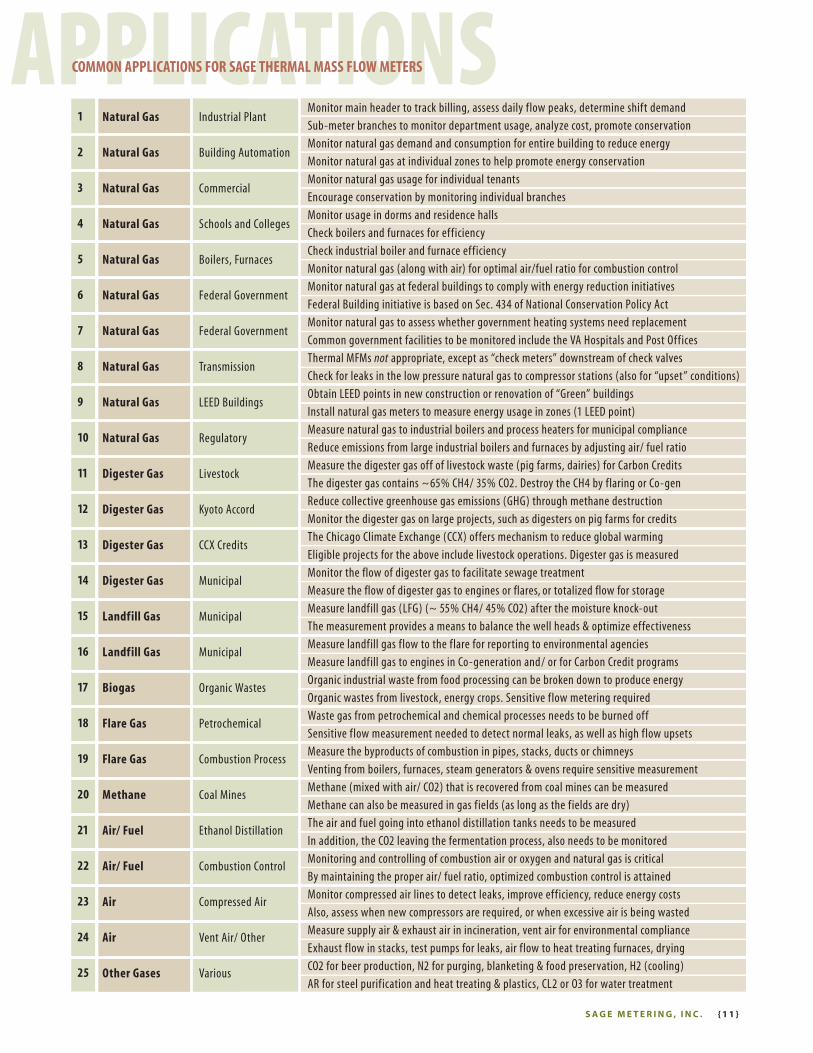
APPLICATIONSCOMMON APPLICATIONS FOR SAGE THERMAL MASS FLOW METERS
S A G E M E T E R I N G , I N C . { 1 1 }

Make the Wise Choice.
Choose Sage Flow Meters.
8 Harris Court, D1 / Monterey, CA 93940
866-677-SAGE (7243) / TEL 831-242-2030 / FAX 831-655-4965
www.sagemetering.com
Rev. 1109