
safeway_CATALOGO_4
4
WA R N I N G S TAT E M E N T SAFETY GUIDE — QUICK ACTION COUPLINGS SafeWay Hydraulics, Inc. WARNING FAILURE, IMPROPER USE OR IMPROPER SELECTION OF THE SYSTEMS AND/OR COMPONENTS DESCRIBED HERE- IN MAY CAUSE DEATH, PERSONAL INJURY AND/OR PROPERTY DAMAGE. This document, as well as all other catalogs, price lists and information provided by SafeWay Hydraulics, Inc., its subsidiaries or authorized distributors, is intended to provide product information and/or system options for further consideration by users having substantial technical expertise. It is imperative that all aspects of any intended use be analyzed and all pertinent information reviewed concerning the component or system in a current product catalog. Due to the variety of operating conditions and applications for these components and systems, the user, through its own analysis, testing and evaluation, is solely responsible for making the final selection of the products and systems and ensuring that all safety, warning and performance requirements of the application or use are met. The components described herein, including without limitation, all component features, specifications, designs, pricing and availability, are subject to change at any time at the sole discretion of SafeWay Hydraulics, Inc. and its subsidiaries at any time without notice. 1. QUICK COUPLINGS CAN FAIL WITHOUT WARNING FOR A VARIETY OF REASONS. ALL EQUIPMENT AND SYSTEMS SHOULD BE OF A FAIL-SAFE DESIGN TO AVOID ENDAN- GERING PERSONS AND PROPERTY. 2. ANY PERSON RESPONSIBLE FOR SELECTING OR USING QUICK COUPLINGS SHOULD READ AND UNDERSTAND THIS SAFETY GUIDE AND HAVE A GOOD UNDERSTAND- ING OF FLUID SYSTEM DESIGN AND MAINTENANCE. 3. SAFEWAY, ITS REPRESENTATIVES AND DISTRIBUTORS DO NOT REPRESENT OR WARRANT THAT ANY QUICK COUPLING IS SUITABLE FOR ANY SPECIFIC USE. THE USER, THROUGH ITS OWN TESTING AND EVALUATION, IS SOLELY RESPONSIBLE FOR FINAL SELECTION OF THE PRODUCTS AND SYSTEMS AND ENSURING THAT ALL SAFETY, WARNING AND PERFORMANCE REQUIRE- MENTS OF THE APPLICATION OR USE ARE MET. Coupler Installation Quick couplings should be located so as not to expose the opera- tor to moving parts, hot parts, the potential of falling, slipping, or other hazardous conditions. Precautions should be taken to not over tighten mating threaded parts during installation. Locking Mechanism Ball locking quick couplings can unintentionally disconnect if they are dragged over obstructions while on the end of a hose, or if the sleeve is bumped or moved enough to cause disconnect. Sleeves designed with flanges, to provide better gripping for gloved hands, are especially susceptible to accidental disconnect and should not be used where these conditions exist. THE SLEEVE LOCK OPTION SHOULD BE CONSIDERED WHERE THERE IS A POTENTIAL FOR UNINTENDED UNCOUPLING. Coupler Size Transmission of power by means of pressurized fluid varies with the system pressure and flow rate. The body size of the coupler must be adequate to keep pressure loss to a minimum to avoid damage due to heat generation or excessive fluid velocity. Mechanical Loads Excessive axial and side forces or vibration can reduce coupler life or cause failure. Pressure When selecting your quick coupling, make sure its maximum oper- ating pressure is equal to, or greater than, the maximum possible system pressure. DO NOT EXCEED THE LIMITS OF THE COU- PLER. Pressure impulse can shorten the life of a coupler. Hose Whip A short length of hose between the tool and the coupler half should be used instead of a rigid mount. This reduces the potential for cou- pler damage and provides some isolation from mechanical vibration which could cause accidental uncoupling. Never try to connect or disconnect the coupler when there is pressure in the system unless you are using a quick coupling designed for that purpose. Environment Environmental conditions including, but not limited to, moisture, water, chemicals, ozone, ultraviolet radiation and air pollutants can cause degradation of coupling components and premature quick coupling failure. Choose the proper body material for use in the environment in which the system is placed. Vacuum Not all quick couplings are suitable or recommended for vacuum service. Quick couplings used in vacuum applications must be selected to ensure that the quick coupling will withstand the vacu- um and pressure of the system. Fluid and Temperature Quick coupling body and seal materials must be compatible with the media and ambient temperature, both steady and transient. DO NOT EXCEED THE LIMITS OF THE COUPLER. Fluid Leaks DO NOT GO NEAR FLUID LEAKS. High pressure leaks of fluid such as oil easily puncture skin and can cause serious injury, gan- grene or death. Relieve pressure before loosening fittings. Do not use fingers or skin to check for leaks. If injured, seek emergency medical help. Immediate surgery is required to remove oil. !
-
Upload
julian-castiblanco -
Category
Documents
-
view
222 -
download
0
description
Mechanical Loads 1. QUICK COUPLINGS CAN FAIL WITHOUT WARNING FOR A VARIETY OF REASONS. ALL EQUIPMENT AND SYSTEMS SHOULD BE OF A FAIL-SAFE DESIGN TO AVOID ENDAN- GERING PERSONS AND PROPERTY. Environment Fluid and Temperature 2. ANY PERSON RESPONSIBLE FOR SELECTING OR USING QUICK COUPLINGS SHOULD READ AND UNDERSTAND THIS SAFETY GUIDE AND HAVE A GOOD UNDERSTAND- ING OF FLUID SYSTEM DESIGN AND MAINTENANCE. Excessive axial and side forces or vibration can reduce coupler life or cause failure.
Transcript of safeway_CATALOGO_4
W A R N I N G S T A T E M E N T
S A F E T Y G U I D E — Q U I C K A C T I O N C O U P L I N G S
SafeWay Hydraulics, Inc.
WARNING
FAILURE, IMPROPER USE OR IMPROPER SELECTION OF THE SYSTEMS AND/OR COMPONENTS DESCRIBED HERE-IN MAY CAUSE DEATH, PERSONAL INJURY AND/OR PROPERTY DAMAGE.
This document, as well as all other catalogs, price lists and information provided by SafeWay Hydraulics, Inc., its subsidiaries or authorizeddistributors, is intended to provide product information and/or system options for further consideration by users having substantial technicalexpertise. It is imperative that all aspects of any intended use be analyzed and all pertinent information reviewed concerning the component or system in a current product catalog. Due to the variety of operating conditions and applications for these components andsystems, the user, through its own analysis, testing and evaluation, is solely responsible for making the final selection of the products andsystems and ensuring that all safety, warning and performance requirements of the application or use are met.
The components described herein, including without limitation, all component features, specifications, designs, pricing and availability, aresubject to change at any time at the sole discretion of SafeWay Hydraulics, Inc. and its subsidiaries at any time without notice.
1. QUICK COUPLINGS CAN FAIL WITHOUT WARNING FOR AVARIETY OF REASONS. ALL EQUIPMENT AND SYSTEMSSHOULD BE OF A FAIL-SAFE DESIGN TO AVOID ENDAN-GERING PERSONS AND PROPERTY.
2. ANY PERSON RESPONSIBLE FOR SELECTING OR USINGQUICK COUPLINGS SHOULD READ AND UNDERSTANDTHIS SAFETY GUIDE AND HAVE A GOOD UNDERSTAND-ING OF FLUID SYSTEM DESIGN AND MAINTENANCE.
3. SAFEWAY, ITS REPRESENTATIVES AND DISTRIBUTORSDO NOT REPRESENT OR WARRANT THAT ANY QUICKCOUPLING IS SUITABLE FOR ANY SPECIFIC USE. THEUSER, THROUGH ITS OWN TESTING AND EVALUATION,IS SOLELY RESPONSIBLE FOR FINAL SELECTION OF THEPRODUCTS AND SYSTEMS AND ENSURING THAT ALLSAFETY, WARNING AND PERFORMANCE REQUIRE-MENTS OF THE APPLICATION OR USE ARE MET.
Coupler InstallationQuick couplings should be located so as not to expose the opera-tor to moving parts, hot parts, the potential of falling, slipping, orother hazardous conditions. Precautions should be taken to notover tighten mating threaded parts during installation.
Locking MechanismBall locking quick couplings can unintentionally disconnect if theyare dragged over obstructions while on the end of a hose, or if thesleeve is bumped or moved enough to cause disconnect. Sleevesdesigned with flanges, to provide better gripping for gloved hands,are especially susceptible to accidental disconnect and should notbe used where these conditions exist. THE SLEEVE LOCK OPTIONSHOULD BE CONSIDERED WHERE THERE IS A POTENTIAL FORUNINTENDED UNCOUPLING.
Coupler SizeTransmission of power by means of pressurized fluid varies with thesystem pressure and flow rate. The body size of the coupler mustbe adequate to keep pressure loss to a minimum to avoid damagedue to heat generation or excessive fluid velocity.
Mechanical LoadsExcessive axial and side forces or vibration can reduce coupler lifeor cause failure.
PressureWhen selecting your quick coupling, make sure its maximum oper-ating pressure is equal to, or greater than, the maximum possiblesystem pressure. DO NOT EXCEED THE LIMITS OF THE COU-PLER. Pressure impulse can shorten the life of a coupler.
Hose WhipA short length of hose between the tool and the coupler half shouldbe used instead of a rigid mount. This reduces the potential for cou-pler damage and provides some isolation from mechanical vibrationwhich could cause accidental uncoupling. Never try to connect ordisconnect the coupler when there is pressure in the system unlessyou are using a quick coupling designed for that purpose.
EnvironmentEnvironmental conditions including, but not limited to, moisture,water, chemicals, ozone, ultraviolet radiation and air pollutants cancause degradation of coupling components and premature quickcoupling failure. Choose the proper body material for use in theenvironment in which the system is placed.
VacuumNot all quick couplings are suitable or recommended for vacuumservice. Quick couplings used in vacuum applications must beselected to ensure that the quick coupling will withstand the vacu-um and pressure of the system.
Fluid and TemperatureQuick coupling body and seal materials must be compatible withthe media and ambient temperature, both steady and transient.DO NOT EXCEED THE LIMITS OF THE COUPLER.
Fluid LeaksDO NOT GO NEAR FLUID LEAKS. High pressure leaks of fluidsuch as oil easily puncture skin and can cause serious injury, gan-grene or death. Relieve pressure before loosening fittings. Do notuse fingers or skin to check for leaks. If injured, seek emergencymedical help. Immediate surgery is required to remove oil.
!
S A F E W A Y H Y D R A U L I C S Document No. 7960 rev. 004
FFE49 Series
Flush FaceNon-Spill,InternationalStandardISO 16028Interchange
No Spillage, High FlowReliable Quick Coupling
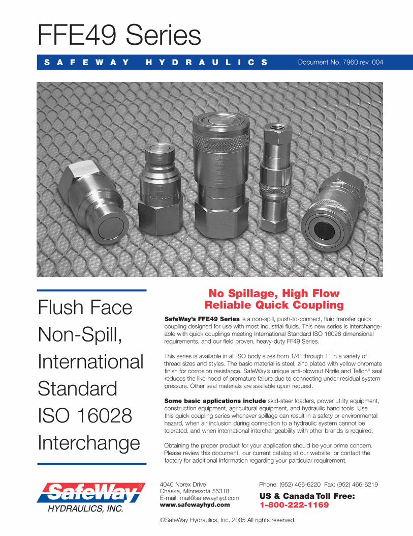
SafeWay’s FFE49 Series is a non-spill, push-to-connect, fluid transfer quickcoupling designed for use with most industrial fluids. This new series is interchange-able with quick couplings meeting International Standard ISO 16028 dimensionalrequirements, and our field proven, heavy-duty FF49 Series.
This series is available in all ISO body sizes from 1/4" through 1" in a variety ofthread sizes and styles. The basic material is steel, zinc plated with yellow chromatefinish for corrosion resistance. SafeWay’s unique anti-blowout Nitrile and Teflon® sealreduces the likelihood of premature failure due to connecting under residual systempressure. Other seal materials are available upon request.
Some basic applications include skid-steer loaders, power utility equipment,construction equipment, agricultural equipment, and hydraulic hand tools. Use this quick coupling series whenever spillage can result in a safety or environmental hazard, when air inclusion during connection to a hydraulic system cannot be tolerated, and when international interchangeability with other brands is required.
Obtaining the proper product for your application should be your prime concern.Please review this document, our current catalog at our website, or contact the factory for additional information regarding your particular requirement.
4040 Norex DriveChaska, Minnesota 55318 E-mail: [email protected]
©SafeWay Hydraulics, Inc. 2005 All rights reserved.
Phone: (952) 466-6220 Fax: (952) 466-6219
US & CanadaToll Free:1-800-222-1169
Complete ISO Body Size Body Size Threaded Size Max. Operating Pressure Rated Flow Max. SpillageCoupler No. (Inches) (Inches) and Description psi (BAR) gpm (Lpm) cc
FFE49-2 1/4 1/4 1/4” Female NPT 5,000 (345) 3 (12) .01
FFE49-3 3/8 3/8 3/8” Female NPT 4,000 (276) 10 (38) .02
FFE49-3-8 3/8 3/8 3/4”-16 Female ORB 4,000 (276) 10 (38) .02
FFE49-4 1/2 3/4 1/2” Female NPT 4,000 (276) 12 (45) .04
FFE49-4-3/4 1/2 3/4 3/4” Female NPT 4,000 (276) 12 (45) .04
FFE49-4-10 1/2 3/4 7/8”-14 Female ORB 4,000 (276) 12 (45) .04
FFE49-4-12 1/2 3/4 1-1/16”-12 Female ORB 4,000 (276) 12 (45) .04
FFE49-6 3/4 1 3/4” Female NPT 4,000 (276) 26 (100) .10
FFE49-6-1 3/4 1 1” Female NPT 4,000 (276) 26 (100) .10
FFE49-6-16 3/4 1 1-5/16”-12 Female ORB 4,000 (276) 26 (100) .10
FFE49-8 1 1-1/4 1” Female NPT 3,000 (207) 50 (189) .20
FFE49-8-114 1 1-1/4 1-1/4” Female NPT 3,000 (207) 50 (189) .20
FFE49-8-20 1 1-1/4 1-5/8”-12 Female ORB 3,000 (207) 50 (189) .20
Temperature Range: Standard Seals (Buna-N) -40° to +250° F. Viton® Option: -15° to +450° F. Other Seals Available.Vacuum Data: 27.4 inches Hg. both connected and disconnected — all sizes.
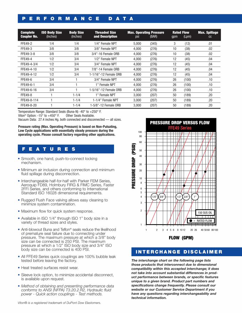
Pressure rating (Max. Operating Pressure) is based on Non-Pulsating, Low Cycle applications with essentially steady pressure during the operating cycle. Please consult factory regarding other applications.
P E R F O R M A N C E D A T A
F E A T U R E S
INTERCHANGE D ISCLA IMER
• Smooth, one hand, push-to-connect locking mechanism.
• Minimum air inclusion during connection and minimumfluid spillage during disconnection.
• Interchangeable half-for-half with Parker FEM Series,Aeroquip FD89, Holmbury FIRG & FIMC Series, Faster2FFI Series, and others conforming to InternationalStandard ISO 16028 dimensional requirements.
• Rugged Flush Face valving allows easy cleaning tominimize system contamination.
• Maximum flow for quick system response.
• Available in ISO 1/4” through ISO 1” body size in avariety of thread sizes and styles.
• Anti-blowout Buna and Teflon® seals reduce the likelihoodof premature seal failure due to connecting under pressure. The maximum pressure at which a 3/8” bodysize can be connected is 250 PSI. The maximum pressure at which a 1/2” ISO body size and 3/4” ISObody size can be connected is 400 PSI.
• All FFE49 Series quick couplings are 100% bubble leaktested before leaving the factory.
• Heat treated surfaces resist wear.
• Sleeve lock option, to minimize accidental disconnect,is available upon request.
• Method of obtaining and presenting performance dataconforms to ANSI (NFPA) T3.20.2.R2, Hydraulic fluidpower - Quick action couplings - Test methods.
Viton® is a registered trademark of DuPont Dow Elastomers.
The interchange chart on the following page lists those products that interconnect due to dimensionalcompatibility within this accepted interchange; it doesnot take into account substantial differences in prod-uct performance between brands, or specific featuresunique to a given brand. Product part numbers andspecifications change frequently. Please consult ourwebsite or our Customer Service Department if youhave any questions regarding interchangeability andtechnical information.
100
80
60
50
40
30
20
10
5
8
6
4
3
2
1
1 2 3 4 5 6 8 1210 2620 40 50 60 80 100
PRES
SURE
DRO
P (P
SID)
FLOW (GPM)
RATED FLOW=
PRESSURE DROP VERSUS FLOW FFE49 Series
1/4" 1/2"3/8" 3/4" 1"
150 SUS OIL
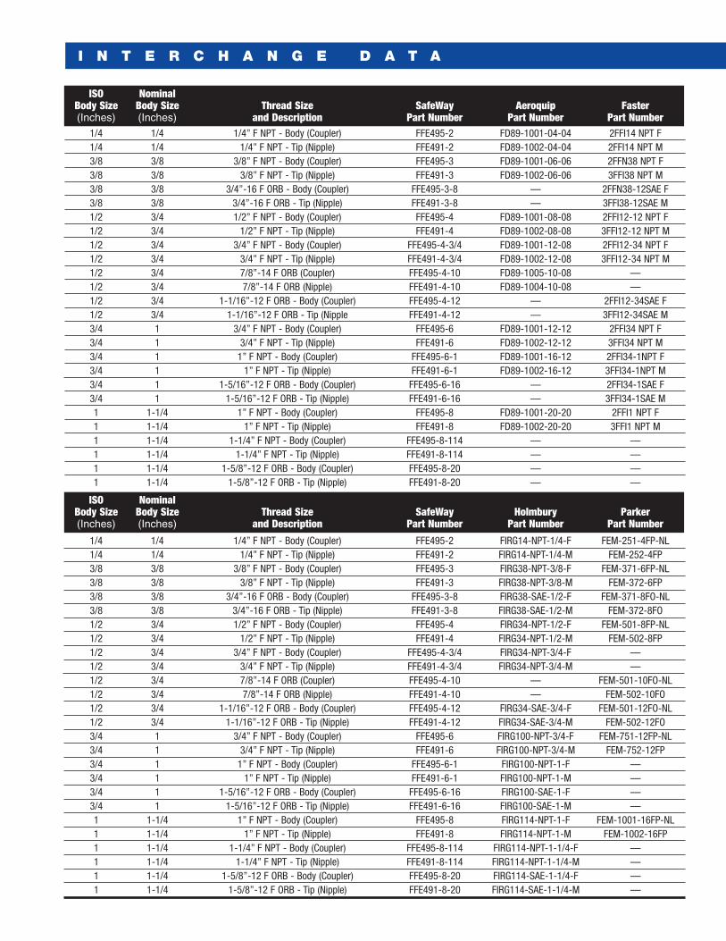
ISO NominalBody Size Body Size Thread Size SafeWay Aeroquip Faster(Inches) (Inches) and Description Part Number Part Number Part Number
1/4 1/4 1/4” F NPT - Body (Coupler) FFE495-2 FD89-1001-04-04 2FFI14 NPT F1/4 1/4 1/4” F NPT - Tip (Nipple) FFE491-2 FD89-1002-04-04 2FFI14 NPT M3/8 3/8 3/8” F NPT - Body (Coupler) FFE495-3 FD89-1001-06-06 2FFN38 NPT F3/8 3/8 3/8” F NPT - Tip (Nipple) FFE491-3 FD89-1002-06-06 3FFI38 NPT M3/8 3/8 3/4”-16 F ORB - Body (Coupler) FFE495-3-8 — 2FFN38-12SAE F3/8 3/8 3/4”-16 F ORB - Tip (Nipple) FFE491-3-8 — 3FFI38-12SAE M1/2 3/4 1/2” F NPT - Body (Coupler) FFE495-4 FD89-1001-08-08 2FFI12-12 NPT F1/2 3/4 1/2” F NPT - Tip (Nipple) FFE491-4 FD89-1002-08-08 3FFI12-12 NPT M1/2 3/4 3/4” F NPT - Body (Coupler) FFE495-4-3/4 FD89-1001-12-08 2FFI12-34 NPT F1/2 3/4 3/4” F NPT - Tip (Nipple) FFE491-4-3/4 FD89-1002-12-08 3FFI12-34 NPT M1/2 3/4 7/8”-14 F ORB (Coupler) FFE495-4-10 FD89-1005-10-08 —1/2 3/4 7/8”-14 F ORB (Nipple) FFE491-4-10 FD89-1004-10-08 —1/2 3/4 1-1/16”-12 F ORB - Body (Coupler) FFE495-4-12 — 2FFI12-34SAE F1/2 3/4 1-1/16”-12 F ORB - Tip (Nipple FFE491-4-12 — 3FFI12-34SAE M3/4 1 3/4” F NPT - Body (Coupler) FFE495-6 FD89-1001-12-12 2FFI34 NPT F3/4 1 3/4” F NPT - Tip (Nipple) FFE491-6 FD89-1002-12-12 3FFI34 NPT M3/4 1 1” F NPT - Body (Coupler) FFE495-6-1 FD89-1001-16-12 2FFI34-1NPT F3/4 1 1” F NPT - Tip (Nipple) FFE491-6-1 FD89-1002-16-12 3FFI34-1NPT M3/4 1 1-5/16”-12 F ORB - Body (Coupler) FFE495-6-16 — 2FFI34-1SAE F3/4 1 1-5/16”-12 F ORB - Tip (Nipple) FFE491-6-16 — 3FFI34-1SAE M1 1-1/4 1” F NPT - Body (Coupler) FFE495-8 FD89-1001-20-20 2FFI1 NPT F1 1-1/4 1” F NPT - Tip (Nipple) FFE491-8 FD89-1002-20-20 3FFI1 NPT M1 1-1/4 1-1/4” F NPT - Body (Coupler) FFE495-8-114 — —1 1-1/4 1-1/4” F NPT - Tip (Nipple) FFE491-8-114 — —1 1-1/4 1-5/8”-12 F ORB - Body (Coupler) FFE495-8-20 — —1 1-1/4 1-5/8”-12 F ORB - Tip (Nipple) FFE491-8-20 — —
ISO NominalBody Size Body Size Thread Size SafeWay Holmbury Parker(Inches) (Inches) and Description Part Number Part Number Part Number
1/4 1/4 1/4” F NPT - Body (Coupler) FFE495-2 FIRG14-NPT-1/4-F FEM-251-4FP-NL1/4 1/4 1/4” F NPT - Tip (Nipple) FFE491-2 FIRG14-NPT-1/4-M FEM-252-4FP3/8 3/8 3/8” F NPT - Body (Coupler) FFE495-3 FIRG38-NPT-3/8-F FEM-371-6FP-NL3/8 3/8 3/8” F NPT - Tip (Nipple) FFE491-3 FIRG38-NPT-3/8-M FEM-372-6FP3/8 3/8 3/4”-16 F ORB - Body (Coupler) FFE495-3-8 FIRG38-SAE-1/2-F FEM-371-8FO-NL3/8 3/8 3/4”-16 F ORB - Tip (Nipple) FFE491-3-8 FIRG38-SAE-1/2-M FEM-372-8FO1/2 3/4 1/2” F NPT - Body (Coupler) FFE495-4 FIRG34-NPT-1/2-F FEM-501-8FP-NL1/2 3/4 1/2” F NPT - Tip (Nipple) FFE491-4 FIRG34-NPT-1/2-M FEM-502-8FP1/2 3/4 3/4” F NPT - Body (Coupler) FFE495-4-3/4 FIRG34-NPT-3/4-F —1/2 3/4 3/4” F NPT - Tip (Nipple) FFE491-4-3/4 FIRG34-NPT-3/4-M —1/2 3/4 7/8”-14 F ORB (Coupler) FFE495-4-10 — FEM-501-10FO-NL1/2 3/4 7/8”-14 F ORB (Nipple) FFE491-4-10 — FEM-502-10FO1/2 3/4 1-1/16”-12 F ORB - Body (Coupler) FFE495-4-12 FIRG34-SAE-3/4-F FEM-501-12FO-NL1/2 3/4 1-1/16”-12 F ORB - Tip (Nipple) FFE491-4-12 FIRG34-SAE-3/4-M FEM-502-12FO3/4 1 3/4” F NPT - Body (Coupler) FFE495-6 FIRG100-NPT-3/4-F FEM-751-12FP-NL3/4 1 3/4” F NPT - Tip (Nipple) FFE491-6 FIRG100-NPT-3/4-M FEM-752-12FP3/4 1 1” F NPT - Body (Coupler) FFE495-6-1 FIRG100-NPT-1-F —3/4 1 1” F NPT - Tip (Nipple) FFE491-6-1 FIRG100-NPT-1-M —3/4 1 1-5/16”-12 F ORB - Body (Coupler) FFE495-6-16 FIRG100-SAE-1-F —3/4 1 1-5/16”-12 F ORB - Tip (Nipple) FFE491-6-16 FIRG100-SAE-1-M —1 1-1/4 1” F NPT - Body (Coupler) FFE495-8 FIRG114-NPT-1-F FEM-1001-16FP-NL1 1-1/4 1” F NPT - Tip (Nipple) FFE491-8 FIRG114-NPT-1-M FEM-1002-16FP1 1-1/4 1-1/4” F NPT - Body (Coupler) FFE495-8-114 FIRG114-NPT-1-1/4-F —1 1-1/4 1-1/4” F NPT - Tip (Nipple) FFE491-8-114 FIRG114-NPT-1-1/4-M —1 1-1/4 1-5/8”-12 F ORB - Body (Coupler) FFE495-8-20 FIRG114-SAE-1-1/4-F —1 1-1/4 1-5/8”-12 F ORB - Tip (Nipple) FFE491-8-20 FIRG114-SAE-1-1/4-M —
I N T E R C H A N G E D A T A


