SAFETY VERIFICATION OF CABLE SYSTEM FOR SUSPENSION OF …
10
SAFETY VERIFICATION OF CABLE SYSTEM FOR SUSPENSION OF WORKERS Structures 03 May 2016
Transcript of SAFETY VERIFICATION OF CABLE SYSTEM FOR SUSPENSION OF …

SAFETY VERIFICATION OF CABLE SYSTEM FOR SUSPENSION OF WORKERS
Structures
03 May 2016

File Project
Template_Collinson_W1.docx Safety verification of cable system for suspension of workers
Document Type Project Nr
Base of Design P_2016
Project Stage Discipline
Technical Note Structures
Publication Date File Safety Verification of Cable System for Suspension of Workers.docx
E00 03/05/2016
Description Technical Note
Designed Checked Approved
JME MP MP
Publication Data File
Description
Designed Checked Approved
Publication Data File
Description
Designed Checked Approved
Publication Data File
Description
Designed Checked Approved
Publication Data File
Description
Designed Checked Approved
Publication Data File
Description
Designed Checked Approved
Safety verification of cable system for suspension of workers | Structures
INDEX
1. Terms of Reference ................................................................................................. 1
2. Standards and Codes ............................................................................................. 1
3. Materials .................................................................................................................. 2
4. Design Actions ........................................................................................................ 2
5. Analysis and Design ............................................................................................... 2
5.1. Calculation Procedure ................................................................................................................... 2
5.2. Results and requirements ............................................................................................................. 4

1
Safety verification of cable system for suspension of workers | Structures
1. Terms of Reference
The current Technical Note concerns to the safety verification of a cable system designed for the support
of suspended workers, as shown in Picture 1. The suspension cable is anchored at the steel rebar of not
yet casted concrete columns.
Picture 1 – Cable for support of workers.
The technical department of Grupo Casais, have been appointed to undertake the safety verification for the
described situation. This document provides the Basis of Design and is deemed to comply the standards
and codes implemented.
2. Standards and Codes
The present building structure is to be designed in accordance with the following European Standards
currently implemented:
NP EN 1990 - Eurocode 0 – Basis of structural design;
NP EN 1991 1-1 - Eurocode 1 (1-1) – Actions on Structures: Part 1.1 - Densities, self-weight and
imposed loads;
NP EN 1992 1-1 - Eurocode 2 (1-1) – Design of concrete structures: Part 1.1 - Design of concrete
structures. General rules and rules for buildings;
NP EN 1993 1-1 - Eurocode 3 (1-1) – Design of steel structures: Part 1.1 - General rules and rules
for buildings;
NP EN 206 1 - Concrete: Specification, performance, production & conformity
RSA – Regulamento de Segurança e Ações para Estruturas de Edifícios e Pontes;
REBAP – Regulamento de Estruturas e Betão Armado e Pré-Esforçado;
REAE - Regulamento de Estruturas de Aço para Edifícios.

2
Safety verification of cable system for suspension of workers | Structures
3. Materials
The materials used in the structure are:
Cast in-situ reinforced concrete
o Class C 30/37 (Superstructure);
o Steel Rebar S 500 N R (Fyk = 500 N/mm2)
For normal loading conditions, the material partial safety factors indicated below are to be applied:
Reinforcement (prestressing steel included) 1.15
Concrete in flexure or axial load 1.50
Safetop Cable Ref. 80266
Picture 2 – SafeTop Cable Ref. 80266.
4. Design Actions
Characteristic Normal Loads
Reinforced Concrete 25.0 kN/m3
Steel Rebar 78.6 kN/m3
Permanent Load (1 Worker) - P 1.08 kN
5. Analysis and Design
5.1. Calculation Procedure
For calculation purposes a person with 𝑃 = 1.08 𝑘𝑁 of weight is considered to be working at the position
𝑥 = 𝐿 3 = 2.67 𝑚⁄ (𝐿 – Distance between anchorage points = 8.0m), according to Picture 3.
A minimum Cable Deflection (𝑓) of 250mm must be guaranteed at the point of application of P Load.
3
Safety verification of cable system for suspension of workers | Structures
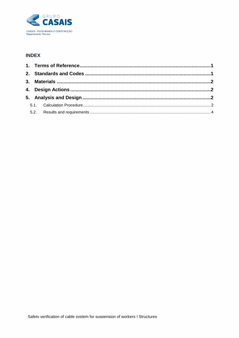
The following expressions are used to obtain the horizontal reactions (𝐹𝐻1, 𝐹𝐻2) at each anchorage point.
𝐹𝐻1 =𝑁 × 𝑃 × 𝑄
tan(𝜃1)×
𝑥
𝐿 (1) 𝐹𝐻2 =
𝑁 × 𝑃 × 𝑄
tan(𝜃2)×
(𝐿 − 𝑥)
𝐿 (2)
where N number of workers suspended at the same time = 1.
Q Impact Factor = 2.0.
θ Deflection Angle. tan(𝜃1) equals to 𝑓 𝑥⁄ ; tan(𝜃2) equals to 𝑓 (𝐿 − 𝑥)⁄ ;
f Cable Deflection = 250mm.
Picture 3 – Structural model. Picture 4 – Cross-Section A-A’
The maximum bending moment MEd at Cross-Section A-A´ is obtained using expression 3.
𝑀𝐸𝑑 = 𝐹𝐻 × 𝐻 = 23.04 𝑘𝑁. 𝑚 (3)
where H distance between the top of the concrete column and the top of the steel bars (= 0.75m).
Bending Moment MEd is converted to an equivalent force binary (NCEd and NTed, according to Picture 4). In
this particular case the maximum force applied in a steel bar is obtained by the following expression.
𝑁𝐶𝐸𝑑 = 𝑁𝑇𝐸𝑑 =𝑀𝐸𝑑 𝑎⁄
𝑁𝑐𝑏 + 𝑁𝑡𝑏
= 28.80 𝑘𝑁 (4)
where NCEd, NTed compression and tension force at a steel bar, respectively (= 28.80 kN);
a distance between steel bars, according to Picture 4 (= 0.20 m);
Ncb, Ntb number of steel compressed and tensioned bars, respectively (= 2 + 2);
The design buckling resistance of the compression member is verified according to EN 1993-1-1 as follows:
𝑁𝐸𝑑
𝑁𝑏,𝑅𝑑
≤ 1.0 =28.80
31.00= 0.93 ≤ 1.00 (𝑂𝐾!) (4)
where NEd is the design value of the compression force (= NCEd = 28.80 kN);
NbRd is the design buckling resistance of the compression member (= 31.00 kN).
6Ø25 FH
MEd
NCEd
NTEd
a a
A2 A’2 A’1 A1
H

4
Safety verification of cable system for suspension of workers | Structures
The detailed calculations and results may be consulted at Annexe A.
5.2. Results and requirements
The calculation procedures and results are valid for the specific conditions described in this document
according to Picture 3 and Picture 4. All calculations must be rechecked if geometry is changed.
All safety requirements are verified as long as the following requirements are met:
Only one person is working at a time.
A minimum Cable Deflection (f) of 250mm is guaranteed at the point of application of P Load.
The distance (L) between anchorage points is not more than 8 meters.
The distance (H) between the top of the concrete columns and the top of the steel bars is not more
than 0.75 meters.
The distance (a) between steel bars is not less than 0.20m.

5
Safety verification of cable system for suspension of workers | Structures
Annexe A
Detailed Calculations. Safety verification according to EN 1993-1-1.

Annexe A
1.0 Cross-Section and Material properties
Ø (mm) Ø (m) A (m2) I (m
4) i (m) E (GPa) fy (MPa)
25 0.025 0.00049 1.92E-08 0.00625 200 500
2.0 Design axial force on the compressed steel bar
30.72 kN
1.00
1.08 kN
2.00
8.00 m
250.00 mm
2.67 m
0.20 m
2
2
0.75 m
23.04 kN.m
28.80 kN
6.3 Buckling resistance of members EN 1993-1-1
6.3.1 Uniform members in compression
6.3.1.1 Buckling resistance
(1) A compression member should be verified against buckling as follows:
= 0.93 OK
where NEd is the design value of the compression force;
NB,Rd is the design buckling resitance of the compression member.
= 31.00
where χ is the reduction factor for the relevant buckling mode.
= 0.15
where = 3.85
= 2.37
Bending Moment MEd is converted on an equivalent force binary (NCEd and NTEd):
Force applied at the compressed steel bar (NCEd)
Cross-Section Dimension (a)
Number of Compressed Steel Bars (Ncb)
Number of Tensioned Steel Bars (Ntb)
Height (H)
Horizontal RH reaction on Cable causes a MEd Bending Moment on Column
Horizontal Reaction (RH)
Number of Workers (N)
Weight of Worker (P)
Impact Factor (Q)
Lenght (L)
Cable Deflection (f)
Position of P Weight (x)
Page 1 of 2

Annexe A
Ncr is the elastic force for the relevant buckling mode based on the gross cross sectional properties.
Ncr = = 37.85 kN
L cr,y Buckling Length of Steel Bar 1.00 m
α Imperfection Factor = 0.49
(2) The imperfection factor α corresponding to the appropriate buckling curve should be obteined from Table 6.1
and Table 6.2.
Page 2 of 2


![EFFECT OF DAMPER ON SEISMIC RESPONSE OF CABLE …...long-span bridge. Cable bridges are divided into two types: cable-stayed bridges and suspension bridges [1]. Figure 1 Cable-Supported](https://static.fdocuments.in/doc/165x107/5ebf16e9ea28cd143945860f/effect-of-damper-on-seismic-response-of-cable-long-span-bridge-cable-bridges.jpg)