Safety valve Hygenic Pressure SHP
28
34-36 Avenue Roger Hennequin 78197 Trappes cedex - France Tel.: + 33 (0)1 30 16 15 00 Fax: +33 (0)1 30 16 15 01 Home page: http://www.servinox.com Safety valve Hygenic Pressure SHP Instructions Reference: SHPCE_NOT_EN Version B
Transcript of Safety valve Hygenic Pressure SHP
Device under pressure
Directive 99.1046
PED 97/23/EC
34-36 Avenue Roger Hennequin 78197 Trappes cedex - France Tel.: + 33 (0)1 30 16 15 00 Fax: +33 (0)1 30 16 15 01 Home page: http://www.servinox.com
Safety valve
Hygenic Pressure
SHP
Instructions
Reference: SHPCE_NOT_EN
Version B

SHPCE_NOT_EN version B
We reserve the right to modify our products without notice, including those for which orders have been received.
Page 1
1 INTRODUCTION ......................................................................................................... 2
1.1. The manufacturer ....................................................................................................................................... 2
1.2. Instructions ................................................................................................................................................. 2
1.3. About the equipment .................................................................................................................................. 3
1.4. Signs ........................................................................................................................................................... 4
2 SAFETY INSTRUCTIONS .............................................................................................. 5
2.1. Indications and symbols .............................................................................................................................. 5
2.2. Safety of workers ........................................................................................................................................ 6
2.3. Intended use ............................................................................................................................................... 7
2.4. Breakdown of the risks ................................................................................................................................ 8
3 TECHNICAL SPECIFICATIONS ...................................................................................... 9
3.1. Standard version ......................................................................................................................................... 9
3.2. Forced opening option .............................................................................................................................. 15
3.3. Detection option ..................................................................................................................................... 15
3.4. ATEX option .............................................................................................................................................. 16
4 COMMISSIONING .................................................................................................... 17
4.1. Transport /Reception /Handling................................................................................................................ 17
4.2. Storage ..................................................................................................................................................... 17
4.3. Installation ................................................................................................................................................ 18
5 USE .......................................................................................................................... 21
5.1. Functional checks ...................................................................................................................................... 21
5.2. Adjustment ............................................................................................................................................... 21
6 SERVICING AND MAINTENANCE ............................................................................... 22
6.1. General ..................................................................................................................................................... 22
7 DIAGNOSTIC AID ...................................................................................................... 24
8 WARRANTY ............................................................................................................. 25

SHPCE_NOT_EN version B
We reserve the right to modify our products without notice, including those for which orders have been received.
Page 2
1 INTRODUCTION
1.1. The manufacturer
SERVINOX is a specialist, making process equipment for the brewing, food, cosmetic and chemical industries.
Skill and knowledge about process equipment: In areas such as the protection of tanks, sampling, injection of gas in liquids, scouring or cleaning pipes with patented products.
SERVINOX is certified ISO 9001: 2008 and makes products complying with the following applicable standards and directives:
Pressure Equipment Directive (PED) 2014/68/EU
European Directive concerning Devices for Use in Explosive Atmospheres (ATEX) 2014/34/EC
Hygienic standard for manufacturers US 3A
We are an active member of the association EHEDG France (hygienic standard for European manufacturers).
1.2. Instructions
To ensure the integrity of the device and the safety of people, you should be aware of the information contained in these instructions before installation and utilisation.
Depending on the installation and the fluid, the specific directives and regulations apply, and should be complied with.
In addition to these instructions, the general instructions for safety at work and protection should be applied. The regulations concerning the protection of the environment must also be followed.

SHPCE_NOT_EN version B
We reserve the right to modify our products without notice, including those for which orders have been received.
Page 3
1.3. About the equipment
The SHP safety valves are completely autonomous devices, not requiring any external control for their operation.
It is a safety accessory belonging to category IV of European Directive 2014/68/EU.
It is intended to evacuate at a known pressure rate. Its use is intended for steam, and gases of groups 1 and 2, from 0.5 to 8 bar
Fluid of group 1: explosive fluids, flammable, easily flammable, extremely flammable, very toxic, toxic, oxidising
Fluid of group 2: all the other fluids
Made in stainless steel type 1.4404 (316L), with sealing suitable for the conditions of use.
The opening pressure is created by a stainless-steel spring. The escape is collected.
The valves are designed to function, in basic version, at a maximum admissible pressure (PS) of 8 bars, and a maximum temperature of 200°C (depending on the materials of the seals).
The elastomers and plastomers used are compliant with US FDA.
The hygenic pressure valve type SHP provides
protection against overpressure in your installations.

SHPCE_NOT_EN version B
We reserve the right to modify our products without notice, including those for which orders have been received.
Page 4
1.4. Signs
This device has a sticker , the SERVINOX reference of the product and an SVX trigram accompanied by a production number. The 6-figure number that follows the trigram is the manufacturing order.
If you have difficulties these instructions cannot resolve, you should ask for further information from the manufacturer or from the equipment distributor.
It is essential to mention the SERVINOX order and/or the serial/production order number, beginning with SVX, for all special requests (spare parts, etc).
EC sign This valve of type SHP is suitable for ATEX areas 1 and 21. It has a sign on a metal plate, fixed to the clamp collar, following the model below.
SERVINOX XXXX 34-36, Avenue Roger Hennequin 78190 TRAPPES (France). Tel: +33 (0)1.30.16.15.00 Fax: +33 (0)1.30.16.15.01 E-mail: [email protected] http://www.servinox.com
Year: XXXX Ref: XXXXXXXXX/XXXX Batch N°: OFXXXXX Product N°: X Temperature (TS): 1/XXX°C PS: 8 bar DN: XX mm Opening Pressure (Pdo): XX bar Kd=0.X PT (Test): 12 bar le jj/mm/aaaa Seal made of: XXXXXX
II 2GD C TX

SHPCE_NOT_EN version B
We reserve the right to modify our products without notice, including those for which orders have been received.
Page 5
2 SAFETY INSTRUCTIONS
This technical manual contains basic instructions that should be followed. It is therefore essential to read it before installation and commissioning.
2.1. Indications and symbols
The following pictograms are designed to draw your attention to important points relating to the safety of people and the integrity of the device:
SYMBOL DEFINITION
Direct danger for people
Possible damage to the product or its environment
Useful information and application guidelines
Minimum number required for certain operations.
(The number of characters in the pictogram indicates the minimum number of persons).
Minimum technical skill level.
(the number in red indicates the minimum level required).
Some jobs require special technical skills and qualifications, such as for maintenance repairs or work on electrical equipment.
Three levels specify the required technical skill (knowledge of the equipment concerned, experience, training, etc):
WORKER'S PROFILE QUALIFICATIONS
Level 1 End user with no technical knowledge
Default level if the skill pictogram is not present. Permits only ordinary use and routine maintenance.
Level 2 Experienced professional
Trained and experienced - knowing the equipment and the technologies used.
Level 3 The manufacturer's personnel / expert of the product
Work reserved for the manufacturer of the documented device.

SHPCE_NOT_EN version B
We reserve the right to modify our products without notice, including those for which orders have been received.
Page 6
2.2. Safety of workers
Installation, test, adjustment, maintenance and replacement should be performed:
By qualified persons
Following the recommendations and guidelines given in these instructions
Complying with the arrangements for safety at work, procedures and resources of the fitter, and the legal notifications for the prevention of accidents.
Not following these safety instructions can result in the loss of all right to claim damages.
SHPCE_NOT_EN version B
We reserve the right to modify our products without notice, including those for which orders have been received.
Page 7
2.3. Intended use
Correct utilisation
In the certification documents, associated with the order, check that the device chosen is right for its intended use.
The safety valves are available with various options.
A safety valve is designed to function with a maximum rate and fixed opening pressure.
The end user or operator must verify the compatibility of the materials of the equipment (metals and alloys, seals, etc), with the fluids in contact. And that these fluids never harm the mechanical or physical properties of the components.
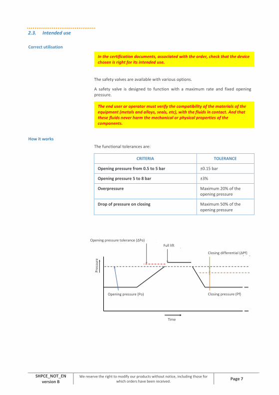
How it works
The functional tolerances are:
CRITERIA TOLERANCE
Opening pressure from 0.5 to 5 bar ±0.15 bar
Opening pressure 5 to 8 bar ±3%
Overpressure Maximum 20% of the opening pressure
Drop of pressure on closing Maximum 50% of the opening pressure
Opening pressure tolerance (ΔPo)
Full lift
Time
Pre
ssu
re
Closing differential (ΔPf)
Closing pressure (Pf) Opening pressure (Po)

SHPCE_NOT_EN version B
We reserve the right to modify our products without notice, including those for which orders have been received.
Page 8
Incorrect utilisation
The device must not be used for any other purpose other than its intended use. The manufacturer cannot be held responsible in case of incorrect utilisation. The sealing must not be damaged or removed. If this is done, the warranty will be void. The manufacturer permits no modification to the valve.
Modifications can affect the functioning of the safety valve. The safety valves, especially the valve's shaft should be completely free.
The levers must not be used to suspend objects. The position of a lever must not be modified. No extra weight should be applied on the levers.
The equipment should not be used beyond the following operating limits:
PARAMETER LIMITS
Maximum admissible pressure The maximum allowable pressure is indicated into
the EC declaration of conformity and the EC
mark of the SHPCE valve.
Maximum utilisation temperature
• Sealing in VMQ or FKM or FFKM
• Sealing in HNBR
• Sealing in EPDM or NBR
+1 / +200°C
+1 / +140°C
+1 / +120°C
2.4. Breakdown of the risks
DANGER / RISK
Hot fluid Very hot surface Aggressive fluid
HARM Burns Burns Burns
PREVENTION
Garments, goggles, suitable
gloves
Suitable gloves Gloves, goggles, suitable mask
SHPCE_NOT_EN version B
We reserve the right to modify our products without notice, including those for which orders have been received.
Page 9
3 TECHNICAL SPECIFICATIONS
3.1. Standard version
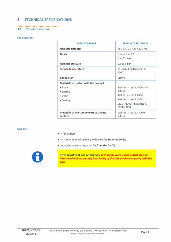
Specifications
SPECIFICATIONS SERVINOX PROPOSAL
Nominal diameter 08 / 13 / 20 / 25 / 32 / 40
Fluids Group 1 and 2
Gas / Steam
Nominal pressure 0.5 to 8 bar
Service temperature 1° (excluding freezing) to 200°C
Connection Clamp
Materials in contact with the product
• Body
• Seating
• Valve
• Sealing
Stainless-steel 1.4404 and 1.4409
Stainless-steel 1.4404
Stainless-steel 1.4404
VMQ, FKM, FFKM, HNBR, EPDM, NBR
Materials of the components excluding contact
Stainless-steel 1.4306 or 1.4307
Options
ATEX option
Forced or manual opening with lever (as from the DN20).
Inductive opening detector (as from the DN20)
After adjustment and verification, each safety valve is lead-sealed. Only an intact lead seal ensures the functioning of the safety valve complying with the sign.

SHPCE_NOT_EN version B
We reserve the right to modify our products without notice, including those for which orders have been received.
Page 10
View of the device
Model: SHP08, SHP13
With button for forced manual opening
Model: SHP13, SHP20, SHP25, SHP32, SHP40
Without lever for forced opening

SHPCE_NOT_EN version B
We reserve the right to modify our products without notice, including those for which orders have been received.
Page 11
Dimensions of the device

SHPCE_NOT_EN version B
We reserve the right to modify our products without notice, including those for which orders have been received.
Page 12

SHPCE_NOT_EN version B
We reserve the right to modify our products without notice, including those for which orders have been received.
Page 13
Parts list of the components of the SHP valve

SHPCE_NOT_EN version B
We reserve the right to modify our products without notice, including those for which orders have been received.
Page 14
REF DESCRIPTION
1 Valve body
2 Valve
3 Piston
4 Shaft
5 Shaft of valve
6 Cap
6.3 Bottom cap
7 Spring guide
8 Screw
9 Nut
10 Stainless-steel spring
11 Clips bracket
12 Clamp collar
13 Seal
14 Seal
15 Guiding band

SHPCE_NOT_EN version B
We reserve the right to modify our products without notice, including those for which orders have been received.
Page 15
3.2. Forced opening option
View of the device
This option concerns the models: SHP13, SHP20, SHP25, SHP32, SHP40
With lever for forced manual opening
3.3. Detection option
The detection of escape opening option is relayed by an inductive detector fitted at the top of the valve. The detector is available in standard version or ATEX.
View of the device
This option concerns the models: SHP20, SHP25, SHP32, SHP40
With opening detector

SHPCE_NOT_EN version B
We reserve the right to modify our products without notice, including those for which orders have been received.
Page 16
3.4. ATEX option
General
ATEX version 2014/34/EC
, areas 1 & 21, gas and dust.
Under no circumstances, does the ATEX version of the product modify the specifications of the product and its components.
This device is intended for use in surface installations (group II).
The protection level of category 2 is suitable for normal use and frequently occurring disturbances for which malfunctions are normally taken into account.
This equipment is for use in areas in which explosive atmospheres caused by mixtures of air and gas (G), vapours, mist or mixtures of air with dust (D), are likely to occur.
The maximum surface temperature is the temperature of the fluid.

SHPCE_NOT_EN version B
We reserve the right to modify our products without notice, including those for which orders have been received.
Page 17
4 COMMISSIONING
4.1. Transport /Reception /Handling
Upon receipt, check:
That the package is in good condition
That the device is delivered as ordered
That the device has not been damaged
If the product has the EC sign:
And that the device is supplied with the EC compliance certificate, whose number must match the maker's plate fixed to the device
If the device is damaged, it must not be fitted on the installation. Contact the manufacturer or equipment distributor.
4.2. Storage
If the device is not fitted immediately after delivery, it should be stored carefully.
It should be stored in its original packaging, in a covered area, with protection against dirt, rain, snow, insects and away from shock.
The safe storage temperature is between 5°C and 40°C, with relative humidity of the air < 50%.
If the device is stored at negative temperatures, the resistance of the materials to cold should be taken into account (e.g.: the seals).
If storage is for longer than one year, the seals need to be replaced before commissioning

SHPCE_NOT_EN version B
We reserve the right to modify our products without notice, including those for which orders have been received.
Page 18
4.3. Installation
General
Before any utilisation of the equipment, the user must visually verify good condition: absence of corrosion, bits of packaging.
If the fluid is harmful, inflammable, toxic, etc, fit the installation with discharge pipes going into a safe place.
Also, you are advised to check the compatibility of these products with the seals and materials before using them.
Before fitting this valve, you should check that the maximum PS of the equipment to protect, is higher or equal to the opening pressure of the valve.
If the installation is outside in low temperature, you should take into account the risk of jamming of the valve by freezing and obstruction of the outlet by snow.
To ensure drainage, the valve outlet pipes should be installed so that it has a slope up to the drain orifice situated at its lowest point.
The outlet pipe must not be directed upwards immediately after the valve. It should be sufficiently sized for ease of access and capable of being inspected regularly.
The fluids flowing out should be recovered (e.g.: by drains, systems of collectors or filters).
The outlet orifice of the safety valve should be protected so that no mould or dirt can enter the valve.
The outlet should be fitted between the horizontal and the vertical (but vertical always oriented downwards) to ensure good drainage. The fluid arrives by the base of the valve. The outlet is perpendicular to the inlet.

SHPCE_NOT_EN version B
We reserve the right to modify our products without notice, including those for which orders have been received.
Page 19
The safety valves should be fitted so that the dynamic vibrations of the installation cannot be transmitted to the safety valves.
Fit the safety valves so that no static and thermic stress, of an inadmissible level, and coming from the upstream and downstream pipes can be transmitted to the valve.
Also, take into account, when fitting, the forces of reaction which occur when opening and any dilatation due to the temperature during use. Systems preventing this dilatation should be fitted.
Do not place blocking devices before the safety valve.
SORTIE = Escape ENTREE = Equipment to be protected
The workers
The work described below should be carried out by qualified and experienced persons.
The personnel must be fitted with gloves, helmet, and safety shoes.
Fitting
Place the entry of the valve on the clamp connector side, tank or pipes, inserting a suitable clamp seal and tighten the clamp collar.
The connections should be made complying with the standards in force.
Dismantling
Drain the supply pressure from the equipment protected by the valve and unlock the clamp collar linking your installation to the valve.

SHPCE_NOT_EN version B
We reserve the right to modify our products without notice, including those for which orders have been received.
Page 20
Inlet pipe
The inlet pipes must be as short as possible, to ensure cleaning the seating.
Outlet pipe
The pipes must not exert stress on the valve.
Fit valve outlet pipes in a design favouring flow. The outlet pipes should be designed according to each condition of utilisation. There is a difference between systems of evacuation for steam or gas.
The valve outlet pipes functioning on steam and gas should be designed to ensure a discharge from the valve safely, and no loss of charge at the outlet (at the rate of evacuation of the valve). Collecting the evacuation must not generate a back-pressure with escape at the rate planned.

SHPCE_NOT_EN version B
We reserve the right to modify our products without notice, including those for which orders have been received.
Page 21
5 USE
5.1. Functional checks
During use, check the functioning of the safety valve every 6 months.
To make sure that the valve is functional, you are advised to perform a flush. This flush can only be done if the service pressure is at least equal to 75% of the opening pressure.
Without lifting system
Create a brief and controlled overpressure, compared with the calibration of the valve. If this starts at the calibrated pressure (± statutory tolerance), the functioning is normal.
With manual lifting system
In order to verify the correct functioning of the valve, use the manual lifting system of the valve. Hold the handle and carry out a ¼ turn, around the shaft linking the system to the central shaft. If the rise occurs without any particular problem, this means that the O-ring providing the seal between the outside and the inside of the valve body, is in good condition and therefore that there is no problem.
Verification of the good closing of the valve under-pressure.
However, depending on the calibration of the valve, it can be more or less hard to lift the valve manually.
5.2. Adjustment
The work described below should be carried out by qualified and experienced persons.
This safety valve is governed by the directive of Device Under Pressure, and lead-sealed. Because of this, adjustment is reserved for the manufacturer of the documented device.
Contact SERVINOX or your distributor.

SHPCE_NOT_EN version B
We reserve the right to modify our products without notice, including those for which orders have been received.
Page 22
6 SERVICING AND MAINTENANCE
6.1. General
The equipment requires maintenance to make sure it functions correctly.
An inspection must be carried out at regular intervals. An initial inspection interval of 6 months is recommended.
Certain properties of fluids (corrosive, aggressive, abrasive, residues, viscosity, etc) and certain environmental conditions (climate, pollution, etc) may require a reduction of these inspection intervals.
SERVINOX supplies the spare parts for proper maintenance and the warranty on the equipment.
We keep a store of sachets of wear parts (seals, etc) and we recommend that you keep a few sachets in stock for quick jobs.
Inspections and servicing
The minimum points to inspect are:
INSPECTION DIAGNOSTIC
POSITIVE? REACTION
Traces of corrosion?
The valve must not be
used
Contact the manufacturer
Deterioration of the seating and/or the valve of the valve?
Contact the manufacturer
Pronounced wear of the seals?
Contact the manufacturer
Presence of impurities in the valve and/or between the
seating surfaces?
Remove the impurities and perform a test of
functioning
Loosening of the assemblies Tighten and perform a
test of functioning
Poor functioning of the valve Contact the
manufacturer
SHPCE_NOT_EN version B
We reserve the right to modify our products without notice, including those for which orders have been received.
Page 23
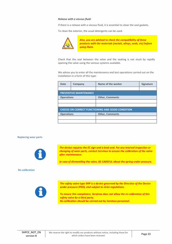
Release with a viscous fluid:
If there is a release with a viscous fluid, it is essential to clean the seal gaskets.
To clean the exterior, the usual detergents can be used.
Also, you are advised to check the compatibility of these products with the materials (metals, alloys, seals, etc) before using them.
Check that the seal between the valve and the seating is not stuck by rapidly opening the valve using the various systems available.
We advise you to enter all the maintenance and test operations carried out on the installation in a form of this type:
Date Company Name of the worker Signature
PREVENTIVE MAINTENANCE
Operations Other, Comments
CHECKS ON CORRECT FUNCTIONING AND GOOD CONDITION
Operations Other, Comments
Replacing wear parts
Re-calibration
The device requires the EC sign and a lead seal. For any internal inspection or changing of wear parts, contact Servinox to ensure the calibration of the valve after maintenance.
In case of dismantling the valve, BE CAREFUL about the spring under pressure.
The safety valve type SHP is a device governed by the Directive of the Device under pressure (PED), and subject to strict regulations.
To ensure this compliance, Servinox does not allow the re-calibration of this safety valve by a third party. Re-calibration should be carried out by Servinox personnel.

SHPCE_NOT_EN version B
We reserve the right to modify our products without notice, including those for which orders have been received.
Page 24
7 DIAGNOSTIC AID
The table below is a diagnostic aid and is intended to help you remedy simple functional problems.
PROBLEM POSSIBLE CAUSE REMEDY
The valve does not open at the intended opening pressure
The rod is blocked by an outside obstacle
Do not hinder the free movement of the rod, in outlet or inlet.
The valve remains open An obstacle hinders the travel of the rod
Do not limit the travel of the rod, in entry or outlet
The safety valve is not sealed Impurities are present between the seating surfaces
Perform a flush.
If the valve is still not sealed after this flush, contact the manufacturer or equipment distributor.
The connection is not sealed Poor tightness of the collars Check the tightness of the collars.
If the valve is still not sealed, contact the manufacturer or equipment distributor.
The fluid escapes from the cap
The valve seal is damaged Contact the manufacturer or equipment distributor.
The mobile parts are jammed Abrasive or corrosive fluids Carry out a maintenance of the valve after each opening in presence of viscous, abrasive, corrosive fluids.
Ice, reduction of the flow The fluid solidifies because of too low ambient temperature
Protect the safety valve and the pipes from cold
SHPCE_NOT_EN version B
We reserve the right to modify our products without notice, including those for which orders have been received.
Page 25
8 WARRANTY
Unless otherwise stated in the proposal, the device is guaranteed 12 months as from the date of delivery.
After an examination in our factory, the parts considered as defective will be replaced at our expense.
All replacement of the device's components (wear parts, seal, etc) must be replaced by SERVINOX original parts The warranty does not cover damage due to: Poor fitting, inappropriate or abusive utilisation
An accident or incorrect installation
Modification of the equipment
Leaks following the passage of impurities will not be taken into account
Required maintenance not performed
The warranty on our products covers the free repair of parts returned when proved that they have become unusable prematurely, following a manufacturing or material fault.
We are not bound to any compensation or any other obligation of this kind.
This equipment has been inspected before leaving the factory.
This equipment has been certified as having been
inspected and authorised for sale

SHPCE_NOT_EN version B
We reserve the right to modify our products without notice, including those for which orders have been received.
Page 26
Notes

SHPCE_NOT_EN version B
We reserve the right to modify our products without notice, including those for which orders have been received.
Page 27
34-36 Avenue Roger Hennequin 78197 Trappes cedex - France Tel.: + 33 (0)1 30 16 15 00 Fax: +33 (0)1 30 16 15 01 Home page: http://www.servinox.com