Safety signal module Q173DSXY Safety...
26
MITSUBISHI MOTION CONTROLLER Safety signal module Q173DSXY Safety Information Thank you for purchasing the Mitsubishi Motion controller. The Motion controller is suitable for establishing safety observation functions for general industrial machinery. Prior to use, please read both this manual and detailed manual thoroughly and familiarize yourself with the product. All rights reserved • Specified product properties and technical data do not represent a guarantee declaration. © 2012 MITSUBISHI ELECTRIC CORPORATION
Transcript of Safety signal module Q173DSXY Safety...
MITSUBISHI MOTION CONTROLLER Safety signal module Q173DSXY
Safety Information
Thank you for purchasing the Mitsubishi Motion controller. The Motion controller is suitable for establishing safety observation functions for general industrial machinery.
Prior to use, please read both this manual and detailed manual thoroughly and familiarize yourself with the product.
All rights reserved • Specified product properties and technical data do not representa guarantee declaration.
© 2012 MITSUBISHI ELECTRIC CORPORATION

1
REVISIONS
The manual number is given on the bottom left of the back cover. Print Date Manual Number Revision Jan., 2012 IB(NA)-0300186-A First edition Jun., 2012 IB(NA)-0300186-B Revision for according to certification of safety standard
[Partial correction] Section 1.1, 2.3, 2.4, 2.6, 7.1, 7.2 [Addition] Chapter 8
Jun., 2014 IB(NA)-0300186-C Revision for according to addition of safety communication function French translation added [Partial correction] Section 2.3, 2.6, 7.1
This manual confers no industrial property rights or any rights of any other kind, nor does it confer any patent licenses. Mitsubishi Electric Corporation cannot be held responsible for any problems involving industrial property rights which may occur as a result of using the contents noted in this manual.
2012 MITSUBISHI ELECTRIC CORPORATION
2
1 About this manual
1.1 Related Manuals
This manual describes the mounting of the safety signal module (Q173DSXY) of a Motion controller. For detailed information of the products, refer to each user's manual or programming manual. Can obtain the PDF data of latest manual from our website. 1.2 Function of this document
This manual instructs the technical staff of the machine manufacturer and/or of the machine operator on the safe mounting of the safety signal module of the Motion controller. In addition mounting protective devices also requires specific technical skills which are not detailed in this documentation. This manual does not provide descriptions the machine in which the Motion controller is, or will be, integrated. Information of this kind will be found in the manuals for the machine.
3
2 On safety
This chapter deals with your own safety and the safety of the equipment operators. • Please read this chapter carefully before beginning with the installation. 2.1 Qualified safety personnel The Motion controller may only be installed by qualified safety personnel. Qualified safety personnel are defined as persons who … • have undergone the appropriate technical training and • have been instructed by the responsible machine operator in the operation of the machine
and the current valid safety guidelines and • have access to the Motion controller manuals and have read and familiarized themselves
with them and • have access to the manuals for the protective devices (e.g. light curtains) connected to the
Motion controller and have read and familiarized themselves with them. 2.2 Applications of the device The Motion controller is a configurable controller for safety applications. It can be used (Declaration of conformity No. BCN-B61008-076) • in accordance with EN ISO 13849-1 : 2008 Category 3 PL d • in accordance with EN 62061 SIL CL 2 The degree of safety actually attained depends on the external circuit, the realization of the wiring, the parameter configuration, the choice of the pick-ups and their location at the machine. Opto-electronic and tactile safety sensors (e.g. light curtains, laser scanners, safety switches, sensors, emergency-stop buttons) are connected to the Motion controller and are linked logically. The corresponding actuators of the machines or systems can be switched off safely via the switching outputs of the Motion controller. 2.3 Correct use
!CAUTION
The Motion controller fulfills the requirements of industrial applications in accordance with the "Interference emission" basic specifications! The Motion controller is therefore only suitable for use in an industrial environment and not for private use.
The Motion controller may only be used within specific operating limits (voltage, temperature, etc., refer to the technical data and to the section "Applications areas of the device"). It may only be used by specialist personnel and only at the machine at which it was mounted and initially commissioned by qualified personnel in accordance with the "Motion controller Programming Manual (Safety Observation)" and " Motion controller User's Manual". The modules of the Motion controller conform to Class A, Group 1, in accordance with EN 61000-6-4. Group 1 encompasses all the ISM devices in which intentionally generated and/or used conductor-bound RF energy that is required for the inner function of the device itself occurs.
4
Mitsubishi Electric Corporation accepts no claims for liability if the equipment is used in any other way or if modifications are made to the device, even in the context of mounting and installation. UL/CSA applications: • Use 60°C/75°C conductors. • The terminal tightening torque must be 5-7 lbs in. • To be used in a Pollution Degree 2 environment only. • The safety observation functions are not evaluated by UL. The approval is accomplished
according to UL508, general use applications. In the system using the safety signal module, the Motion CPU and PLC CPU described in the below list, safety observation function is achieved by writing safety parameters and safety sequence program to the Motion CPU and PLC CPU. Make parameter setting correctly. Incorrect setting may disable the protective functions such as safety observation functions. Refer to "Motion controller programming manual (Safety Observation)" for the detail to set a safety parameters and to make a safety sequence program. (1) Module list (safety observation function built-in product)
Product name Model name
PLC CPU module (Note-1)
Q03UDCPU, Q04UDHCPU, Q06UDHCPU, Q10UDHCPU, Q13UDHCPU, Q20UDHCPU, Q26UDHCPU, Q03UDECPU, Q04UDEHCPU, Q06UDEHCPU, Q10UDEHCPU, Q13UDEHCPU, Q20UDEHCPU, Q26UDEHCPU, Q50UDEHCPU, Q100UDEHCPU
Motion CPU module Q173DSCPU, Q172DSCPU, Q173DCPU-S1, Q172DCPU-S1Safety signal module Q173DSXY Main base unit Q35DB, Q38DB, Q312DB
(Note-1): Use PLC CPU module which the first five digits of the serial number are "10102" or later.
(2) Operating system software list (safety observation function built-in product)
Model name Compatible CPU Version SW8DNC-SV22QJ, SW8DNC-SV13QJ Q173DSCPU "00A" or later (Note-2)
"00E" or later (Note-3)SW8DNC-SV22QL, SW8DNC-SV13QL Q172DSCPU SW8DNC-SV22QA, SW8DNC-SV13QB Q173DCPU-S1 "00N" or later (Note-1)
"00S" or later (Note-2)SW8DNC-SV22QC, SW8DNC-SV13QD Q172DCPU-S1 (Note-1): In the case of using only safety signal comparison function. (Note-2): In the case of using both safety signal comparison function and speed monitoring
function. (Note-3): In the case of using safety observation functions in safety signal comparison
function, speed monitoring function, and safety communication function.
5
2.4 General protective notes and protective measures
!CAUTION
Observe the protective notes and measures Please observe the following items in order to ensure proper use of the Motion controller.
• When mounting, installing and using the Motion controller, observe the standards and
directives applicable in your country. • The national/international rules and regulations apply to the installation, use and periodic
technical inspection of the Motion controller, in particular: – Machinery Directive 2006/42/EC – EMC Directive 2004/108/EC – Low-Voltage Directive 2006/95/EC – The work safety regulations/safety rules
• Manufacturers and owners of the machine on which a Motion controller is used are responsible for obtaining and observing all applicable safety regulations and rules. For Declaration of Conformity (DoC), MITSUBISHI ELECTRIC EUROPE B.V., declares that the Motion controllers are in compliance with the necessary requirements and standards (2006/42/EC, 2004/108/EC and 2006/95/EC). You can obtain the copy of Declaration of Conformity from our website.
• Observe the contents of "Motion controller programming manual (Safety Observation)" • The tests must be carried out by specialized personnel or specially qualified and authorized
personnel and must be recorded and documented to ensure that the tests can be reconstructed and retraced at any time by third parties.
• The external voltage supply of the device must be capable of buffering brief main voltage failures of 20ms as specified in IEC 60204-1.
• The system may not start up normally if power is restored immediately after shut down (within five seconds). Wait for five seconds or longer before restoring power.
2.5 Disposal Disposal of unusable or irreparable devices should always occur in accordance with the applicable country-specific waste-disposal regulations (e.g. European Waste Code 16 02 14). 2.6 Residual risks Define all risk assessments and residual risks for the whole machine to ensure safety. The company and/or individuals who constructed the system take responsibility for everything in terms of safety system installation and commission. In addition, to correspond to EC Machinery Directive, the safety standard needs to be certified as the whole system. Execute all risk assessment and safe level verification for the equipment and the whole system. It is recommended to use third-party certifier as a final certifier of the system. The residual risk in safety observation function of this product is shown below. • This function does not detect errors among the parameters and programs that are set by
you. Therefore, safety of machines cannot be secured unless the safety operation test is performed on the machines.
6
• At the shipment to end-users, confirm the safety related setting by monitoring status and
displayed details of the programming tools and displays. Also, record and save the setting data of safety-related information and programming tools by using check sheet, etc.
• Safety cannot be secured unless assembling, installation, wiring and adjustment of the machine are completed. For the installation, wiring and adjustment, follow the instructions in the user’s manual of each module.
• Only qualified personnel are authorized to install, start-up, repair or service the machines in which components are installed. Only trained engineers should install and operate the equipment. (ISO 13849-1 Table F.1 No.5)
• Separate the wiring for safety observation function from other signal wirings. (ISO 13849-1 Table F.1 No.1)
• Protect the cables with appropriate ways (routing them in a cabinet, using a cable guard, etc.)
• To use the switch, relay and sensor which complies with the safety standards is recommended. In case of using the switch, relay and sensor which does not comply with the safety standard, please apply them for the certifications.
• Keep the required clearance/creepage distance depending on voltage. • Time to detect the safety observation error depend on the process cycle of safety
observation of each CPU. The residual risk in each function of safety observation function is shown below. (1) Safety signal comparison
• Make sure that the mounting location of the safety signal module, MT Developer2 number head device, and GX Works2/GX Developer I/O assignments are correctly set.
• When a signal error occurs, make sure that safety is secured within the signal mismatch permissible time that is set by a parameter.
• Even when a signal error occurs, the servo motor does not stop automatically. Give a (forced) stop command and execute a forced stop processing.
• Make sure that the ladder name to be written to a PLC CPU is not the same as that of sequence programs for safety observation.
• Make sure that the safety signal is properly input via two different paths. • Make sure that the screws will not get loose after fixing the connector on the safety
signal module. • Make sure that all the modules are firmly inserted into the main base unit or extension
base unit. • Scan time processing must be within 100ms so that PLC CPU performs the comparison
function within a certain process time. Make sure that the program contents can be handled less than 100ms. If the scan time is 100ms or longer, PLC CPU should be added for safety to distribute the load of the safety process.

7
(2) Speed monitoring function (SLS)
• Under the condition that the failure rate of the additional pulse encoder components does not exceed 195FIT/395FIT the resulting PFD/PFH will be less than 195FIT/395FIT. (See below diagram.)
Common Comp.
Common(PSU)
PLC
Motion
Q173DSXY
QnUDHCPUand Q3nDB
PLCI/O
MotionI/O
Q17 DSCPU
ch A
ch B
Encoder MR-J4- B
PLG
Additional PulseEncoder Comp.
• Avoid the continuous use (about 8 hours) of the same Speed Monitor parameter block
to prevent the accumulation of errors. • Speed monitoring function guarantees the motor control (the motor rotation speed), but
it does not guarantee the actual machine safety speed. Make sure to set parameters so that the safe speed of the machine is the same as the safety speed of the motor.
• When SLS function of speed zero (stop) does not have command data from a controller, please switch to SOS function or must use external sensor (PLG) together.
• The accuracy of safety speed observation depends on the performance of the external auxiliary pulses which is external input pulse. Therefore, when using external auxiliary pulses, the number of the external input pulses for safety speed must be determined considering the external auxiliary pulses resolution and the allowance input pulse frequency.
• Check if the rotation speed of the monitored servo axis is the same as the actual speed by using a tachometer, etc. considering the speed includes an error caused by the encoder resolution of the external auxiliary input pulses.
• The defect of the mechanical section such as slid of shaft and wanting of a timing belt, etc is not covered. Be sure to eliminate the risk of mechanical section before operation.
• Speed monitoring error detection time is set to in the unit of 10ms, but the time resolution in the actual operation is 25ms. Error in shorter than this time are not detected.
• Create sequence program so that Scan time is within 25ms to make sure that PLC CPU performs the safety monitoring function within a certain process time. If scan time is 25ms or longer, PLC CPU should be added to distribute the load of the process.
• Safety observation error (shutdown signal OFF) does not occur during the time set by the safety monitoring parameters after speed is over the limit. Make sure that safety can be ensured during this period.
• The error occurs when detected speed is different between the motor encoder and the external auxiliary input pulse, and the time required to detect the error depends on the frequency of the external auxiliary pulse. Determine the number of external input pulse considering the error detection risk.
(3) Safe Speed Monitor (SSM)
• If the safety output condition of SSM is used as a restart trigger, incidental start-up cannot be prevented. A restart interlock must comply with EN60204-1. However, using it as the operation ready signal is possible.
8
(4) Shut-off function (STO, SS1)
• STO function disables energy supply to the servo motor by electrical shut-off. The function does not mechanically disconnect electricity from the motor. Therefore, it cannot prevent exposure to electric shock, install a magnetic contactor or a molded case circuit breaker to the main circuit power supply (L1, L2, and L3) of the servo amplifier.
• STO function can disable the energy to servo motor by the electrical shutoff. This function does not guarantee the procedure of stopping the servo motor and deceleration control.
• SS1 function only guarantees the delay time before STO becomes effective. • If SS1 delay time is shorter than servo motor deceleration time, or forced stop function
has an error, STO becomes effective during motor rotation, dynamic brake stop or free-run stop is activated.
• Even if STO function becomes effective with a STO switch, voltage may be left in the servo motor due to the inherent delay of the equipment.
• When the servo amplifier is replaced, make sure that new one is the same type as the old one. After installation, make sure to check the performance of safety observation function before operating the system.
• Check the safety at a certain cycle, or with machinery which is defined by the safety standard to prevent the accumulation of failures. Check the safety at least once a day regardless of system safety level.
• If a power module of a servo amplifier shorted at the upper and lower positions, the servo motor axis rotates half at maximum. For a linear servo motor, the primary side will move a distance of pole pitch.
• Make sure to supply STO input signals (STO1, STO2) from one power supply. Otherwise, the STO function may not function properly due to a sneak current, failing to bring the STO shut-off state.
• For the STO I/O signals of the STO function, supply power by using a safety extra low voltage (SELV) power supply with the reinforced insulation.
(5) Standstill monitoring (SS2, SOS)
• The position dependent safety observation function (SOS) is based on two independent safety-related sensors. One of them is part of the motor, which has a built-in encoder (for functional motion control); the other must be provided by the customer's application (e.g. an external sensor, PLG).
• During Safe Operating Stop, make sure that monitoring status is enabled by small oscillation before a certain period of time (about one hour) elapses in the stop status. However, an error cannot be detected in the check interval. (The derivation of failure until next check cannot be detected.) If stop time becomes long, use Safe Brake Control (SBC) as mechanical rock or perform Safe Torque Off (STO).
• Avoid the continuous use of Safe Operating Stop (SOS) for eight hours or more to prevent the accumulation of failure. If stop time becomes long, use Safe Brake Control (SBC) as mechanical lock or perform Safe Torque Off (STO).
• Encoder position feedback data does not guarantee the range out of the small oscillation. Therefore, make sure that motor encoder feedback position can operate normally in the machine mobile region. At least, the performance check of motor mobile region is required.
• The position assurance of the motor with SOS is 1.75 pulses with the external auxiliary input pulse conversion.
9
(6) Safe Brake Control (SBC)
• This function guarantees only that power to mechanic break is properly supplied. Abrasion of the brake cannot be detected. Make sure regularly if the mechanic brake can operate.
(7) Safety Communication Function
• The safety communication function cannot detect an incorrect servo amplifier station number setting. Check that the station number setting for the Motion control program and the axis select rotary switch setting of servo amplifier match.
• For servo amplifiers that support the safety communication function, check that safety communication is connected.
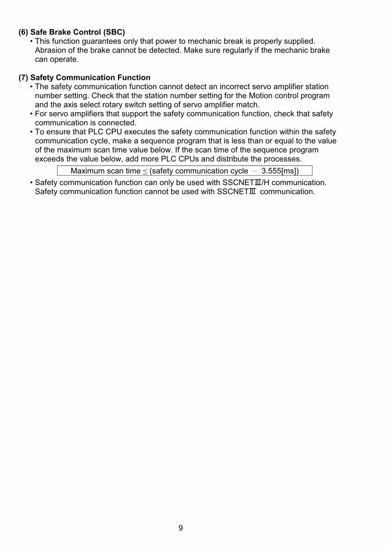
• To ensure that PLC CPU executes the safety communication function within the safety communication cycle, make a sequence program that is less than or equal to the value of the maximum scan time value below. If the scan time of the sequence program exceeds the value below, add more PLC CPUs and distribute the processes.
Maximum scan time ≤ (safety communication cycle 3.555[ms])
• Safety communication function can only be used with SSCNET /H communication. Safety communication function cannot be used with SSCNET communication.
10
3 Conditions of use for the product (1) Motion controller complies with a safety standard, but this fact does not guarantee that
Product will be free from any malfunction or failure. The user of this Product shall comply with any and all applicable safety standard, regulation or law and take appropriate safety measures for the system in which the Product is installed or used and shall take the second or third safety measures other than the Product. MELCO is not liable for damages that could have been prevented by compliance with any applicable safety standard, regulation or law.
(2) MELCO prohibits the use of Products with or in any application involving, and MELCO shall not be liable for a default, a liability for defect warranty, a quality assurance, negligence or other tort and a product liability in these applications. 1) power plants, 2) trains, railway systems, airplanes, airline operations, other transportation systems, 3) hospitals, medical care, dialysis and life support facilities or equipment, 4) amusement equipments, 5) incineration and fuel devices, 6) handling of nuclear or hazardous materials or chemicals, 7) mining and drilling, 8) and other applications where the level of risk to human life, health or property are
elevated.
4 Product description
4.1 Safety signal module Q173DSXY
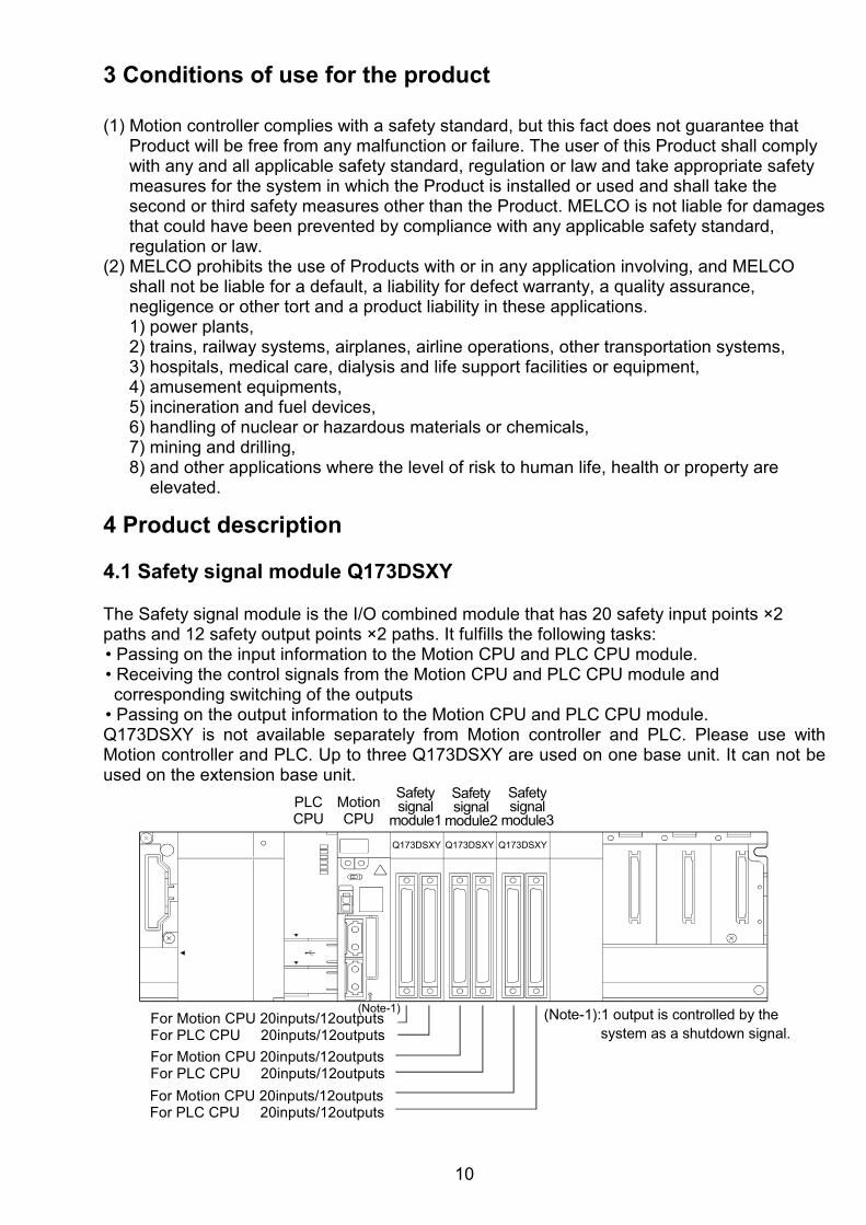
The Safety signal module is the I/O combined module that has 20 safety input points ×2 paths and 12 safety output points ×2 paths. It fulfills the following tasks: • Passing on the input information to the Motion CPU and PLC CPU module. • Receiving the control signals from the Motion CPU and PLC CPU module and corresponding switching of the outputs
• Passing on the output information to the Motion CPU and PLC CPU module. Q173DSXY is not available separately from Motion controller and PLC. Please use with Motion controller and PLC. Up to three Q173DSXY are used on one base unit. It can not be used on the extension base unit.
Q173DSXY
(Note-1)For Motion CPU 20inputs/12outputsFor PLC CPU 20inputs/12outputs
For Motion CPU 20inputs/12outputsFor PLC CPU 20inputs/12outputs
For Motion CPU 20inputs/12outputsFor PLC CPU 20inputs/12outputs
(Note-1):1 output is controlled by the system as a shutdown signal.
Q173DSXY Q173DSXY
PLCCPU
MotionCPU
Safetysignal
module1
Safetysignal
module2
Safetysignal
module3
11
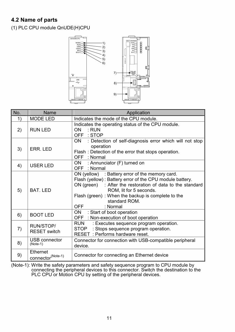
4.2 Name of parts (1) PLC CPU module QnUDE(H)CPU
Q03UDECPU
MODERUNERR.
USERBAT.
BOOT
PULL
USB
10BASE-T/100BASE-TX
100M
SD/RD
USER
MODERUNERR.
BAT.BOOT
Q03UDECPU
RESET RUN
STOP
EJECT
CARD
10BASE-T/100BASE-TX
100M
SD/RD
1)2)3)4)5)6)
7)
8)
9)
No. Name Application
1) MODE LED Indicates the mode of the CPU module.
2) RUN LED Indicates the operating status of the CPU module. ON : RUN OFF : STOP
3) ERR. LED
ON : Detection of self-diagnosis error which will not stop operation
Flash : Detection of the error that stops operation. OFF : Normal
4) USER LED ON : Annunciator (F) turned on OFF : Normal
5) BAT. LED
ON (yellow) : Battery error of the memory card. Flash (yellow) : Battery error of the CPU module battery. ON (green) : After the restoration of data to the standard
ROM, lit for 5 seconds. Flash (green) : When the backup is complete to the
standard ROM. OFF : Normal
6) BOOT LED ON : Start of boot operation OFF : Non-execution of boot operation
7) RUN/STOP/ RESET switch
RUN : Executes sequence program operation. STOP : Stops sequence program operation. RESET : Performs hardware reset.
8) USB connector (Note-1)
Connector for connection with USB-compatible peripheral device.
9) Ethernet connector(Note-1) Connector for connecting an Ethernet device
(Note-1): Write the safety parameters and safety sequence program to CPU module by
connecting the peripheral devices to this connector. Switch the destination to the PLC CPU or Motion CPU by setting of the peripheral devices.

12
(2) Motion CPU Q173DSCPU
0
8
C
4
0
8
C
4
1 2SW
Q173DSCPU
CN
1C
N2
RIOFRONT
EMI
PE
RIP
HE
RA
L
I/F
STOP RUN
EX
T.I
/F
PULL
4)
6)
2)
7)
1)
3)
5) 8)
Front face
10)
Bottom
9)
No. Name Application
1) 7-segment LED Indicates the operating status and error information.
2) Rotary function select 1 switch
• Set the operation mode. (Normal operation mode, Installation mode, Mode operated by ROM, etc)
• When user safety sequence program writes to CPU is a rotary switch setting "1" is set to.
3) Rotary function select 2 switch (Note-1)
4) RUN/STOP switch RUN : Motion program is started. STOP : Motion program is stopped.
5) Forced stop input connector (EMI)
Input to stop all axes of servo amplifier in a lump
6) SSCNET CN1 connector
Connector to connect the servo amplifier of system 1 (up to 16 axes)
7) SSCNET CN2 connector
Connector to connect the servo amplifier of system 2 (up to 16 axes)
8) PERIPHERAL I/F connector (Note-2)
For communication I/F with peripheral devices
9) Internal I/F connector Connector to connect the manual pulse generator/incremental synchronous encoder, or to input/output the signals.
10) RIO connector For the connection with Safety signal module (Q173DSXY) connector.
(Note-1): In the case of monitoring or writing the safety sequence program of the Motion CPU,
communicate from the peripheral devices (GX Works2/GX Developer) by setting the rotary switch to "1". Restart of system is not needed after changing switch. "Other than 1": Communication with MT Devloper2 is possible.
(Used when writing safety parameters) "1" : Communication with GX Works2/GX Developer is possible.
(Used when writing safety sequence program to the Motion CPU) (Note-2): Write the safety parameters and safety sequence program to CPU module by
connecting the peripheral devices in this connector. Switch the destination to the PLC CPU or Motion CPU by setting of the peripheral devices.

13
(3) Safety signal module Q173DSXY
1)
3)
Q173DSXY
PLCIO
MotionIO
Q173DSXY
FR
ON
TR
IO2
RIO
1S
W
2)
8 0
4
C
4)
5)
6)
Front Face Bottom
No. Name Application
1) I/O indicator LED
Used to indicate the I/O status (on/off). (Only the PLC)
2) Motion IO connector
The safety signal connector Motion CPU
3) PLC IO connector
The safety signal connector PLC CPU
4) Rotary switch for station number setting
For setting of the module station numberModule 1 → Setting 0 Module 2 → Setting 1 Module 3 → Setting 2
5) RIO1 connector RIO communication connector for Motion CPU
Connect to Motion CPU "RIO", or other safety signal unit "RIO2" connected
6) RIO2 connector RIO communication connector for Motion CPU Connect to other safety signal unit "RIO2" connected
• Connection example of the Motion controller and safety signal module
Motion CPUBottom of Q17 DSCPU
Safety signal module1Bottom of Q173DSXY
SW setting"0"
Safety signal module2Bottom of Q173DSXY
Safety signal module3Bottom of Q173DSXY
SW setting"1"
SW setting"2"
RIO cableQ173DSXYCBL M
78
0F
6
E
5
D
4
C
3
B
2
A
1
9
78
0F
6
E
5
D
4
C
3
B
2
A
1
9
78
0F
6
E
5
D
4
C
3
B
2
A
1
9
RIO
RIO2
RIO1 RIO1 RIO1
RIO2 RIO2RIO cableQ173DSXYCBL M
RIO cableQ173DSXYCBL M
14
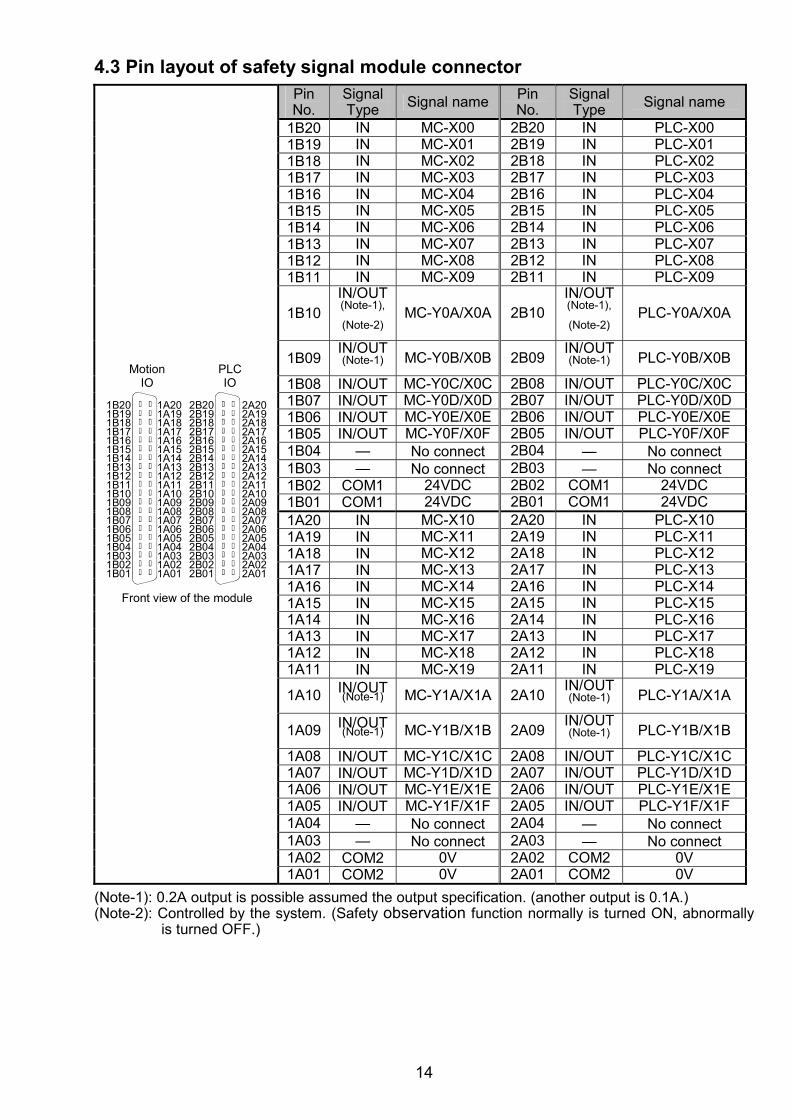
4.3 Pin layout of safety signal module connector
MotionIO
1B201B191B181B171B161B151B141B131B121B111B101B091B081B071B061B051B041B031B021B01
1A201A191A181A171A161A151A141A131A121A111A101A091A081A071A061A051A041A031A021A01
Front view of the module
PLCIO
2B202B192B182B172B162B152B142B132B122B112B102B092B082B072B062B052B042B032B022B01
2A202A192A182A172A162A152A142A132A122A112A102A092A082A072A062A052A042A032A022A01
Pin No.
Signal Type Signal name Pin
No. Signal Type Signal name
1B20 IN MC-X00 2B20 IN PLC-X001B19 IN MC-X01 2B19 IN PLC-X011B18 IN MC-X02 2B18 IN PLC-X021B17 IN MC-X03 2B17 IN PLC-X031B16 IN MC-X04 2B16 IN PLC-X041B15 IN MC-X05 2B15 IN PLC-X051B14 IN MC-X06 2B14 IN PLC-X061B13 IN MC-X07 2B13 IN PLC-X071B12 IN MC-X08 2B12 IN PLC-X081B11 IN MC-X09 2B11 IN PLC-X09
1B10 IN/OUT(Note-1),
(Note-2)
MC-Y0A/X0A 2B10IN/OUT (Note-1),
(Note-2)
PLC-Y0A/X0A
1B09 IN/OUT(Note-1)
MC-Y0B/X0B 2B09
IN/OUT (Note-1)
PLC-Y0B/X0B
1B08 IN/OUT MC-Y0C/X0C 2B08 IN/OUT PLC-Y0C/X0C1B07 IN/OUT MC-Y0D/X0D 2B07 IN/OUT PLC-Y0D/X0D1B06 IN/OUT MC-Y0E/X0E 2B06 IN/OUT PLC-Y0E/X0E1B05 IN/OUT MC-Y0F/X0F 2B05 IN/OUT PLC-Y0F/X0F1B04 — No connect 2B04 — No connect 1B03 — No connect 2B03 — No connect 1B02 COM1 24VDC 2B02 COM1 24VDC1B01 COM1 24VDC 2B01 COM1 24VDC1A20 IN MC-X10 2A20 IN PLC-X101A19 IN MC-X11 2A19 IN PLC-X111A18 IN MC-X12 2A18 IN PLC-X121A17 IN MC-X13 2A17 IN PLC-X131A16 IN MC-X14 2A16 IN PLC-X141A15 IN MC-X15 2A15 IN PLC-X151A14 IN MC-X16 2A14 IN PLC-X161A13 IN MC-X17 2A13 IN PLC-X171A12 IN MC-X18 2A12 IN PLC-X181A11 IN MC-X19 2A11 IN PLC-X19
1A10 IN/OUT(Note-1)
MC-Y1A/X1A 2A10
IN/OUT (Note-1)
PLC-Y1A/X1A
1A09 IN/OUT(Note-1)
MC-Y1B/X1B 2A09
IN/OUT (Note-1)
PLC-Y1B/X1B
1A08 IN/OUT MC-Y1C/X1C 2A08 IN/OUT PLC-Y1C/X1C1A07 IN/OUT MC-Y1D/X1D 2A07 IN/OUT PLC-Y1D/X1D1A06 IN/OUT MC-Y1E/X1E 2A06 IN/OUT PLC-Y1E/X1E1A05 IN/OUT MC-Y1F/X1F 2A05 IN/OUT PLC-Y1F/X1F1A04 — No connect 2A04 — No connect 1A03 — No connect 2A03 — No connect 1A02 COM2 0V 2A02 COM2 0V1A01 COM2 0V 2A01 COM2 0V
(Note-1): 0.2A output is possible assumed the output specification. (another output is 0.1A.) (Note-2): Controlled by the system. (Safety observation function normally is turned ON, abnormally
is turned OFF.)
15
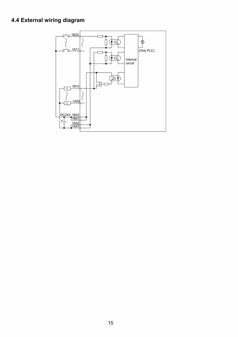
4.4 External wiring diagram
DC24V
L
1B20
1A11
Internalcircuit
1B021B01
1A021A01
1B10
L1A05
+
(Only PLC)
16
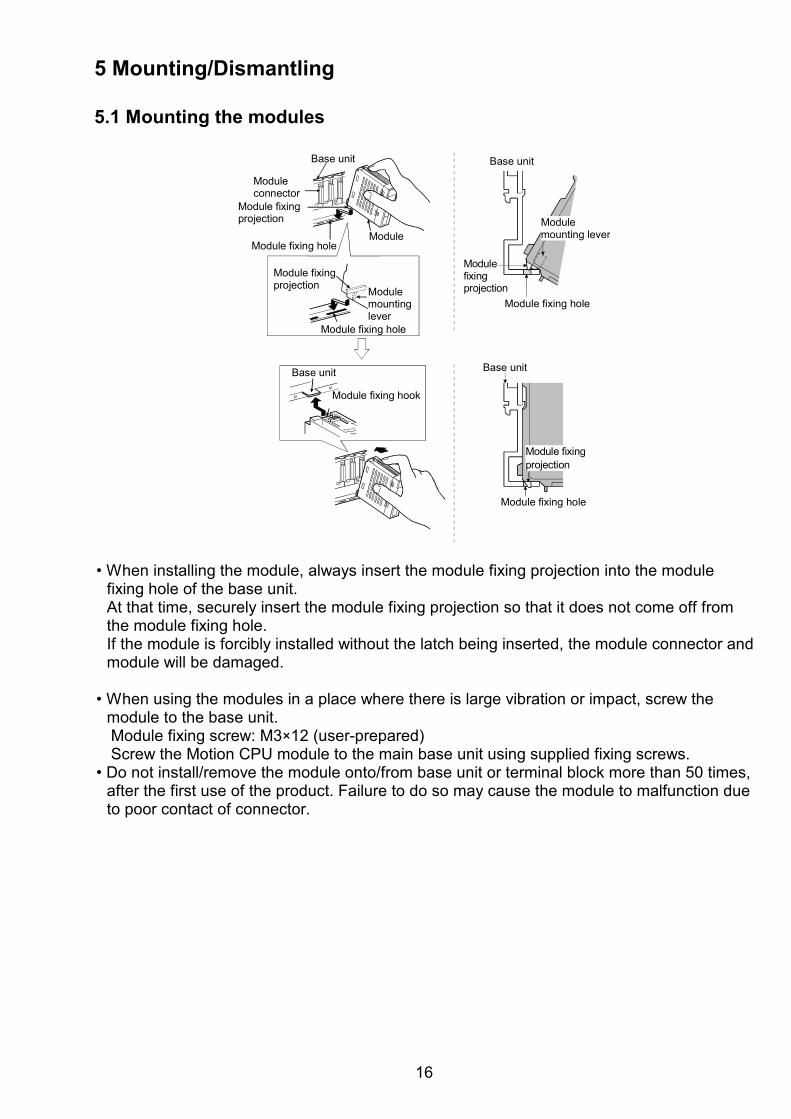
5 Mounting/Dismantling 5.1 Mounting the modules
Base unit
Module fixing projection
Module fixing hole
Module connector
Base unit
Modulemountinglever
Base unit
Module fixing hook
Base unit
Module fixingprojection
Module fixing hole
ModuleModulemounting lever
Modulefixingprojection
Module fixing hole
Module fixingprojection
Module fixing hole
• When installing the module, always insert the module fixing projection into the module
fixing hole of the base unit. At that time, securely insert the module fixing projection so that it does not come off from the module fixing hole. If the module is forcibly installed without the latch being inserted, the module connector and module will be damaged.
• When using the modules in a place where there is large vibration or impact, screw the
module to the base unit. Module fixing screw: M3×12 (user-prepared) Screw the Motion CPU module to the main base unit using supplied fixing screws.
• Do not install/remove the module onto/from base unit or terminal block more than 50 times, after the first use of the product. Failure to do so may cause the module to malfunction due to poor contact of connector.
17
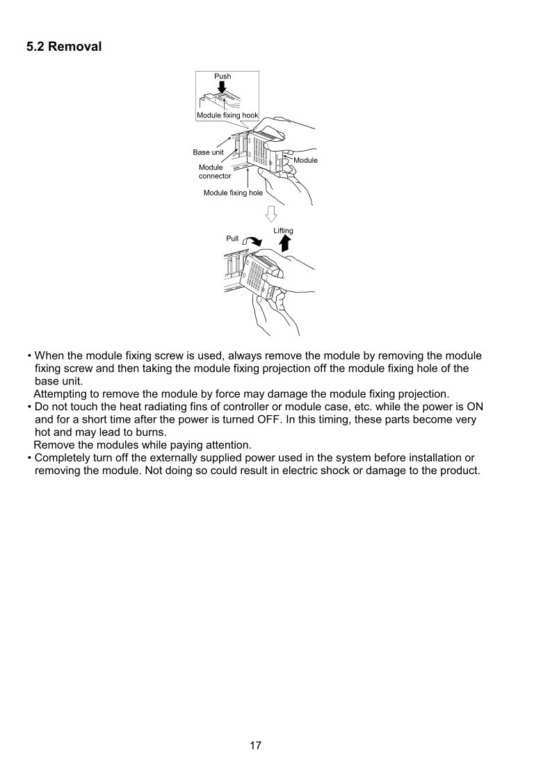
5.2 Removal
Moduleconnector
Module
Module fixing hole
Base unit
Module fixing hook
Push
LiftingPull
• When the module fixing screw is used, always remove the module by removing the module
fixing screw and then taking the module fixing projection off the module fixing hole of the base unit. Attempting to remove the module by force may damage the module fixing projection.
• Do not touch the heat radiating fins of controller or module case, etc. while the power is ON and for a short time after the power is turned OFF. In this timing, these parts become very hot and may lead to burns. Remove the modules while paying attention.
• Completely turn off the externally supplied power used in the system before installation or removing the module. Not doing so could result in electric shock or damage to the product.
18
6 Wiring
!CAUTION
De-energize the entire system The system could start up unexpectedly while you are connecting the devices.
• Select the wire and DC power supply to keep input voltage in the range of 21.6 to 26.4VDC
including the ripple voltage and voltage spike to the safety signal module which is measured at the input connector.
• When wiring in the safety signal module, be sure that it is done correctly by checking the product rated voltage and the terminal layout. Connecting a power supply that is different from the rating or incorrectly wiring the product could result in fire or damage.
• Be sure to use a shield cable for connection of the CTRL connector and external equipment, and avoid running it close to or bundling it with the power and main circuit cables to minimize the influence of electromagnetic interface. (Separate them more than 200mm (0.66ft.) away.)
• Connect the shield wire of the connection cable to the FG terminal of the external equipment.
• Securely tighten the cable connector fixing screws and fixing mechanisms. Insufficient fixing may lead to cables combing off during operation.
• Be sure to wire the cables when power is off. Not doing so may damage the circuit of modules.
• Wire the cable correctly. The safety observation function may not work correctly by wrong wiring. Please make sure the wiring and test sufficiently.

19
7 Technical data 7.1 Safety specification
Item SpecificationCategory Category3 (EN ISO13849-1) Safety Integrity Level SIL CL2 (EN62061)Performance Level PL d (EN ISO13849-1)MTTFd 169 years or longerDC LowPFH 2.17×10 -8 hr -1
Safety observation functions Safety signal comparison, safety communication, STO, SS1, SS2, SOS, SLS, SBC, SSM (IEC61800-5-2:2007)
(Note): Scope of the safety specifications is only processing block.
Input block (including sensor) and output block (contactor and safety servo STO function) are not included.
7.2 General Specifications
Item SpecificationOperating ambient temperature 0 to 55°C (32 to 131°F)
Storage ambient temperature -25 to 75°C (-13 to 167°F)Operating ambient humidity 5 to 95% RH, non-condensing Storage ambient humidity 5 to 95% RH, non-condensing Vibration resistance Compliant with IEC 61131-2 Shock resistance Operating ambience No corrosive gasesOperating altitude (Note-1) 2000m (6562 feet) max. Installation location Inside control panelOvervoltage category (Note-2) II max.
Pollution level (Note-3) 2 max. (Note-1): Do not use or store the Motion controller under pressure higher than the atmospheric
pressure of altitude 0m. Doing so can cause a malfunction. When using the modules under pressure, please contact your sales representative.
(Note-2): This indicates the section of the power supply to which the equipment is assumed to be connected between the public electrical power distribution network and the machinery within premises. Category II applies to the equipment for which electrical power is supplied from fixed facilities. The surge voltage withstand level for up to the rated voltage of 300V is 2500V.
(Note-3): This index indicates the degree that the conductive material is generated in terms of the environment in which the equipment is used. Pollution level 2 is when only non-conductive pollution occurs. A temporary conductivity caused by condensing must be expected occasionally. Mount the Motion controller on a cabinet which meets IP54 in the correct vertical direction to maintain pollution level 2.
7.3 PLC CPU Specifications Item Specification
5VDC internal current consumption 0.33 to 0.55A
External dimensions 98(H) × 27.4(W) × 89.3 to 115(D) mm 3.86(H) × 1.08(W) × 3.52 to 4.53(D) inch
Mass 0.2 to 0.24 kgIncluded items Module×1, Battery (Q6BAT)×1
20
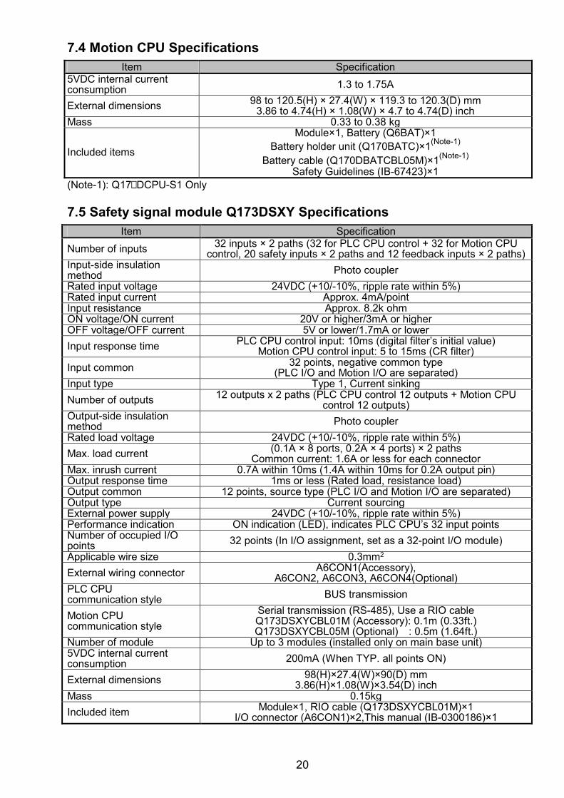
7.4 Motion CPU Specifications
Item Specification5VDC internal current consumption 1.3 to 1.75A
External dimensions 98 to 120.5(H) × 27.4(W) × 119.3 to 120.3(D) mm3.86 to 4.74(H) × 1.08(W) × 4.7 to 4.74(D) inch
Mass 0.33 to 0.38 kg
Included items
Module×1, Battery (Q6BAT)×1 Battery holder unit (Q170BATC)×1(Note-1)
Battery cable (Q170DBATCBL05M)×1(Note-1) Safety Guidelines (IB-67423)×1
(Note-1): Q17 DCPU-S1 Only 7.5 Safety signal module Q173DSXY Specifications
Item Specification
Number of inputs 32 inputs × 2 paths (32 for PLC CPU control + 32 for Motion CPU control, 20 safety inputs × 2 paths and 12 feedback inputs × 2 paths)
Input-side insulation method Photo coupler
Rated input voltage 24VDC (+10/-10%, ripple rate within 5%) Rated input current Approx. 4mA/point Input resistance Approx. 8.2k ohm ON voltage/ON current 20V or higher/3mA or higher OFF voltage/OFF current 5V or lower/1.7mA or lower
Input response time PLC CPU control input: 10ms (digital filter’s initial value)Motion CPU control input: 5 to 15ms (CR filter)
Input common 32 points, negative common type (PLC I/O and Motion I/O are separated)
Input type Type 1, Current sinking
Number of outputs 12 outputs x 2 paths (PLC CPU control 12 outputs + Motion CPU control 12 outputs)
Output-side insulation method Photo coupler
Rated load voltage 24VDC (+10/-10%, ripple rate within 5%)
Max. load current (0.1A × 8 ports, 0.2A × 4 ports) × 2 paths Common current: 1.6A or less for each connector
Max. inrush current 0.7A within 10ms (1.4A within 10ms for 0.2A output pin)Output response time 1ms or less (Rated load, resistance load) Output common 12 points, source type (PLC I/O and Motion I/O are separated)Output type Current sourcing External power supply 24VDC (+10/-10%, ripple rate within 5%) Performance indication ON indication (LED), indicates PLC CPU’s 32 input pointsNumber of occupied I/O points 32 points (In I/O assignment, set as a 32-point I/O module)
Applicable wire size 0.3mm2
External wiring connector A6CON1(Accessory), A6CON2, A6CON3, A6CON4(Optional)
PLC CPU communication style BUS transmission
Motion CPU communication style
Serial transmission (RS-485), Use a RIO cableQ173DSXYCBL01M (Accessory): 0.1m (0.33ft.) Q173DSXYCBL05M (Optional) : 0.5m (1.64ft.)
Number of module Up to 3 modules (installed only on main base unit)5VDC internal current consumption 200mA (When TYP. all points ON)
External dimensions 98(H)×27.4(W)×90(D) mm 3.86(H)×1.08(W)×3.54(D) inch
Mass 0.15kg
Included item Module×1, RIO cable (Q173DSXYCBL01M)×1I/O connector (A6CON1)×2,This manual (IB-0300186)×1
21
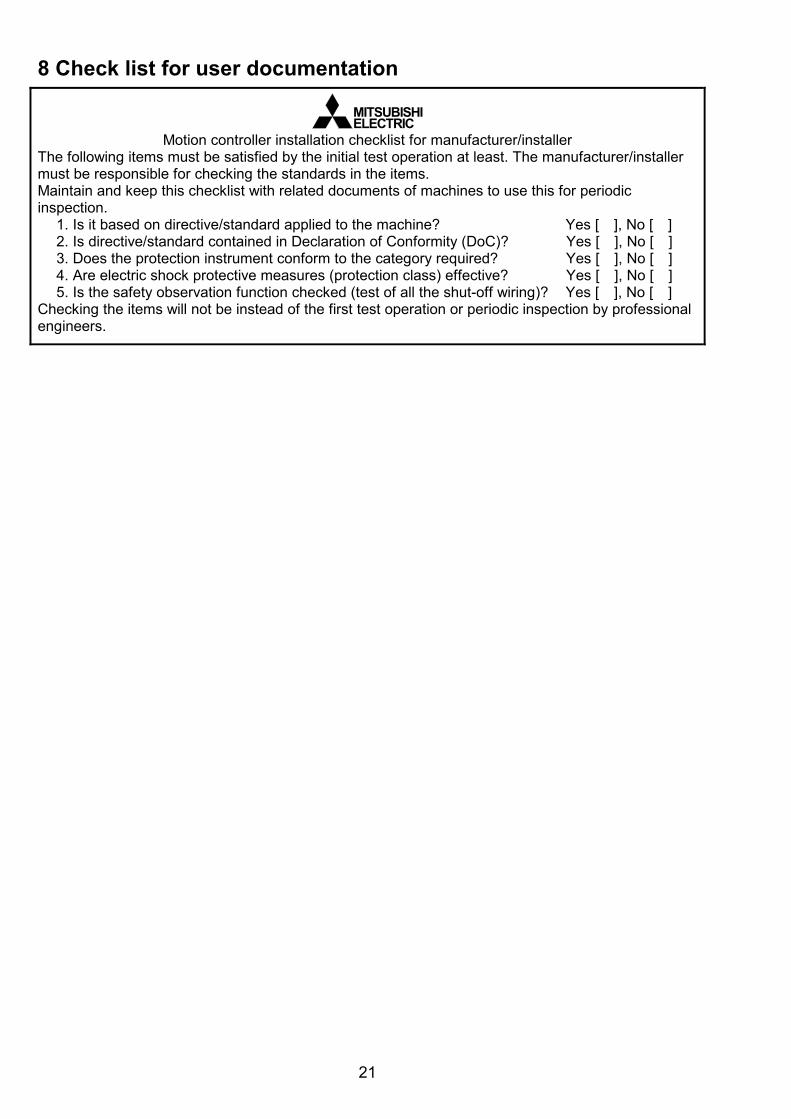
8 Check list for user documentation
MITSUBISHIELECTRIC
Motion controller installation checklist for manufacturer/installer The following items must be satisfied by the initial test operation at least. The manufacturer/installer must be responsible for checking the standards in the items. Maintain and keep this checklist with related documents of machines to use this for periodic inspection.
1. Is it based on directive/standard applied to the machine? Yes [ ], No [ ] 2. Is directive/standard contained in Declaration of Conformity (DoC)? Yes [ ], No [ ] 3. Does the protection instrument conform to the category required? Yes [ ], No [ ] 4. Are electric shock protective measures (protection class) effective? Yes [ ], No [ ] 5. Is the safety observation function checked (test of all the shut-off wiring)? Yes [ ], No [ ]
Checking the items will not be instead of the first test operation or periodic inspection by professional engineers.

22
MEMO

WARRANTY Please confirm the following product warranty details before using this product. 1. Gratis Warranty Term and Gratis Warranty Range
We will repair any failure or defect hereinafter referred to as "failure" in our FA equipment hereinafter referred to as the "Product" arisen during warranty period at no charge due to causes for which we are responsible through the distributor from which you purchased the Product or our service provider. However, we will charge the actual cost of dispatching our engineer for an on-site repair work on request by customer in Japan or overseas countries. We are not responsible for any on-site readjustment and/or trial run that may be required after a defective unit are repaired or replaced.
[Gratis Warranty Term]
The term of warranty for Product is thirty six (36) months after your purchase or delivery of the Product to a place designated by you or forty two (42) months from the date of manufacture whichever comes first "Warranty Period". Warranty period for repaired Product cannot exceed beyond the original warranty period before any repair work.
[Gratis Warranty Range]
(1) You are requested to conduct an initial failure diagnosis by yourself, as a general rule. It can also be carried out by us or our service company upon your request and the actual cost will be charged. However, it will not be charged if we are responsible for the cause of the failure.
(2) This limited warranty applies only when the condition, method, environment, etc. of use are in compliance with the terms and conditions and instructions that are set forth in the instruction manual and user manual for the Product and the caution label affixed to the Product.
(3) Even during the term of warranty, the repair cost will be charged on you in the following cases; 1) A failure caused by your improper storing or handling, carelessness or negligence,
etc., and a failure caused by your hardware or software problem 2) A failure caused by any alteration, etc. to the Product made on your side without our
approval 3) A failure which may be regarded as avoidable, if your equipment in which the
Product is incorporated is equipped with a safety device required by applicable laws and has any function or structure considered to be indispensable according to a common sense in the industry
4) A failure which may be regarded as avoidable if consumable parts designated in the instruction manual, etc. are duly maintained and replaced
5) Any replacement of consumable parts (battery, fan, etc.) 6) A failure caused by external factors such as inevitable accidents, including without
limitation fire and abnormal fluctuation of voltage, and acts of God, including without limitation earthquake, lightning and natural disasters
7) A failure generated by an unforeseeable cause with a scientific technology that was not available at the time of the shipment of the Product from our company
8) Any other failures which we are not responsible for or which you acknowledge we are not responsible for
2. Onerous Repair Term after Discontinuation of Production
(1) We may accept the repair at charge for another seven (7) years after the production of the product is discontinued. The announcement of the stop of production for each model can be seen in our Sales and Service, etc.
(2) Please note that the Product (including its spare parts) cannot be ordered after its stop of production.
3. Service in overseas countries
Our regional FA Center in overseas countries will accept the repair work of the Product; However, the terms and conditions of the repair work may differ depending on each FA Center. Please ask your local FA center for details.
4. Exclusion of Loss in Opportunity and Secondary Loss from Warranty Liability
Whether under or after the term of warranty, we assume no responsibility for any damages arisen from causes for which we are not responsible, any losses of opportunity and/or profit incurred by you due to a failure of the Product, any damages, secondary damages or compensation for accidents arisen under a specific circumstance that are foreseen or unforeseen by our company, any damages to products other than the Product, and also compensation for any replacement work, readjustment, start-up test run of local machines and the Product and any other operations conducted by you.
5. Change of Product specifications
Specifications listed in our catalogs, manuals or technical documents may be changed without notice.
6. Precautions for Choosing the Products
(1) For the use of our Motion controller, its applications should be those that may not result in a serious damage even if any failure or malfunction occurs in Motion controller, and a backup or fail-safe function should operate on an external system to Motion controller when any failure or malfunction occurs.
(2) Our Motion controller is designed and manufactured as a general purpose product for use at general industries. Therefore, applications substantially influential on the public interest for such as atomic power plants and other power plants of electric power companies, and also which require a special quality assurance system, including applications for railway companies and government or public offices are not recommended, and we assume no responsibility for any failure caused by these applications when used. In addition, applications which may be substantially influential to human lives or properties for such as airlines, medical treatments, railway service, incineration and fuel systems, man-operated material handling equipment, entertainment machines, safety machines, etc. are not recommended, and we assume no responsibility for any failure caused by these applications when used. We will review the acceptability of the abovementioned applications, if you agree not to require a specific quality for a specific application. Please contact us for consultation.
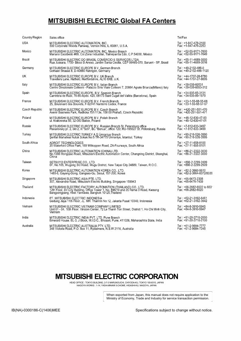
MITSUBISHI ELECTRIC Global FA Centers
MITSUBISHI ELECTRIC CORPORATIONHEAD OFFICE : TOKYO BUILDING, 2-7-3 MARUNOUCHI, CHIYODA-KU, TOKYO 100-8310, JAPAN
NAGOYA WORKS : 1-14, YADA-MINAMI 5-CHOME, HIGASHI-KU, NAGOYA, JAPAN
When exported from Japan, this manual does not require application to theMinistry of Economy, Trade and Industry for service transaction permission.
IB(NA)-0300186-C(1406)MEE Specifications subject to change without notice.