
Safety Shields - Rockford Systems, LLC€¦ · Rockford Systems, LLC reserves the right to make...
80
Safety Shields For Cutting and Turning Machines www.rockfordsystems.com Industrial Machine Safety Solutions
Transcript of Safety Shields - Rockford Systems, LLC€¦ · Rockford Systems, LLC reserves the right to make...
Safety ShieldsFor Cutting and Turning Machines
www.rockfordsystems.com
Industrial Machine Safety Solutions

Customized, EngineeredIntegration Solutions
Machine Safeguarding AssessmentMachine Risk AssessmentTraining and Education
Recommended ForPersonnel in EH&S, Production/ Operations/ Maintenance, and Risk Management roles that need safeguarding training
DescriptionSeminars and webinars that teach people how to safeguard industrial machinery to be in compliance with OSHA regulations, and ANSI/RIA/NFPA standards
Output / ResultSafeguarding Seminar Certificate
Recommended ForOrganizations with new and/or relocated metal working machines or automation cells that need hazard identification and risk scoring
DescriptionIdentifies the task and associated hazards on machinery
Scores the risk level using the ANSI B11.0-2015 safety standard methods
Output / ResultHazard Analysis Report
Recommended ForOrganizations with new, old, refurbished and/or relocated metal working machines, robots or automation cells that need safeguarding solutions and associated costs
DescriptionIdentifies the task and associated hazards on machinery
Recommends safeguarding solutions using the current OSHA regulations, and ANSI/RIA/NFPA standards (or Corporate Standards where applicable) Output / ResultMachine Safeguarding Assessment & Proposal
DELIVERING TRUSTED MACHINE SAFEGUARDING SOLUTIONS FOR ORGANIZATIONS WORKING WITH INDUSTRIAL MACHINERY
SOLUTIONSSAFETYMACHINE
Recommended ForIncluded with Machine Safeguarding Assessment
DescriptionDelivers customized engineered and automated safety device interfaces or specialized controls for machines or robots
Output / ResultMachine Safeguarding Assessment & Proposal
WHY SAFEGUARD?According to Occupational Safety and Health Administration (OSHA) statistics, nearly 18,000 workers in metal fabricating plants suffer non-fatal injuries annually in the United States. Even with strict machine and operator safety regulations in place, unguarded hazardous machinery remains a major source of fatalities, amputations and other traumatic injuries in manufacturing plants. A recent survey showed an alarming 50 percent or more of metal fabricating machinery in the United States are not in compliance with the critical safety requirements for guarding outlined by OSHA and the American National Standards Institute (ANSI).
Since 1971, the Fortune 500 and many of North America’s largest manufacturers have depended upon Rockford Systems for customized machine safeguarding solutions to bring their operations into compliance with today’s OSHA regulations, ANSI, RIA and NFPA standards to ensure they are prepared for tomorrow’s safety challenges.
2 | SAFETY SHIELDS

INTRODUCTION
Ongoing Compliance ValidationTechnical Support andIn-Field SupportExpert Installation Services
Over 10,000Safeguarding Products
Recommended ForIncluded with Machine Safeguarding Assessment
DescriptionEnsures that industrial machines and automation cells are fully safeguarded to OSHA regulations, and ANSI/RIA/NFPA standards
Includes shields, guards, presence sensing devices, controls, disconnects, starters, covers and more for all metal working machines
Output / ResultMachine Safeguarding Assessment & Proposal
Recommended ForIncluded with Machine Safeguarding Assessment
DescriptionOSHA trained installers safely integrate safeguarding products into sophisticated machine controls and train operators on proper use
Output / ResultMachine Safeguarding Assessment & Proposal
Recommended ForIncluded with all purchases and installations
DescriptionEvery purchase is backed up with a professional, highly-trained team of Technical Support Advisers
In-Field Service Technicians are available for more complex troubleshooting and repairs
Output / ResultPost purchase support via phone, fax, online or onsite
Recommended ForOrganizations who have completed a guarding installation that seek ongoing compliance validation
DescriptionEnsures that safeguarding products are inplace, working at optimal performance, and operators are using safeguarding solutions as designed and trained
Output / Result
Included with all Machine Safeguarding Assessment
ROCKFORD SYSTEMS CAN HELPAt Rockford Systems, we are experts at machine guarding because it has been our sole focus for over 45 years. We stand committed to the prevention of injuries and fatalities. We are here to help insurance agencies, academic institutions, and businesses, large and small, address machine safety challenges and to remove the burden of managing the growing legal complexity of OSHA and ANSI requirements from simple turnkey solutions, to more complex customized solutions.
OUR MISSIONOur aim is to enhance the long-term health and quality of life of workers in high-risk occupations, while improving the bottom line of the organizations we serve by increasing compliance, reducing risk, lowering costs, and improving productivity.
SAFETY SHIELDS | 3
TABLE OF CONTENTS
The applications described in this catalog are for instructional and informational purposes only; the photos in this catalog are for illustrative purposes only. They may not represent actual usage. This catalog has been carefully checked for accuracy and is thought to be fully consistent with the products described herein. However, Rockford Systems, LLC does not assume liability for the contents of this publication or for the use of any products described herein. Rockford Systems, LLC reserves the right to make changes to the products and documentation without further notice.
This document contains proprietary information protected by copyright. No part of this catalog may be reproduced, transmitted, stored in a retrieval system, or translated into any language, in any form or by any means without prior written permission from Rockford Systems, LLC, 5795 Logistics Parkway, Rockford, Illinois 61109. Rockford Systems reserves the right to make changes or revisions to the material contained in this catalog and cannot be held liable for incidental or consequential damages resulting from the furnishing, performance or use of this material.
Copyright © 2019 by Rockford Systems, LLC. All rights reserved. Not to be reproduced in whole or in part without written permission. Litho in U.S.A.
INTRODUCTION .................................................................... 5-9
SAFEGUARDING................................................................ 10-61
ELECTRICALLY INTERLOCKED HEAVY-DUTY SHIELDS ...... 10-23
Electrically Interlocked Drill Press Shields .................... 10-13Electrically Interlocked Lathe Chuck Shields ................. 14-16Electrically Interlocked Crosslide/Carriage Travel Lathe Shields .........................................................17Electrically Interlocked Milling Machine Shields ............ 18-20Electrically Interlocked Grinder & Tool Grinder Shields .........21Electrically Interlocked Surface Grinder Shields ..................22Electrically Interlocked Slotting & Broaching Type Machine Shields ...................................................23
SAFETY ON DRILL PRESSES ......................................... 24-27
Safety Chip Shields ..........................................................26Heavy-Duty Aluminum Drill Press Shields ...........................27Spring-Loaded/Self-Ejecting Chuck Keys for Drill Presses ................................................................27
SAFETY ON LATHES ..................................................... 28-37
Sliding Lathe Shields ........................................................30Crosslide-Travel Lathe Shields ...........................................31Small Steel Lathe Chuck Shields .......................................32Large Steel Lathe Chuck Shields .......................................33Transparent Lathe Chuck Shields ......................................34Lathe Mounting Brackets ..................................................35Lathe Chuck Wrenches ............................................... 36-37
SAFETY ON MILLING MACHINES .................................. 38-44
Chip Shields for Bridgeport Mills ................................. 40-41Bridgeport Vertical Mill Controls .........................................41Slide and Swing-Aside Shields .................................... 42-43Rear Shield Assemblies ....................................................43Milling Machine Belt Covers ..............................................44Electrical Interlock Assembly .............................................44
SAFETY ON BENCH GRINDERS ..................................... 45-48
Double-Wheel Grinder Shields ...........................................46Single-Wheel Grinder Shields ............................................46Standard-Mount Grinder Shields .......................................47Heavy-Duty Single Buffer Shield ........................................47Bench Grinder Safety Gauge .............................................48
SAFETY ON BAND SAWS ....................................................49
SAFETY ON DISC AND BELT SANDERS ...............................50
ALL-PURPOSE SHIELDS ............................................... 51-61
Adjustable Slide Shields ....................................................51Rigid-Arm Magnetic-Base Shields .....................................52Universal Ball & Socket Shields ................................... 53-55Flexible Spring-Steel Arm Shields ................................ 56-59On/Off Magnetic-Base Shields ..........................................60Free-Standing Shield Assembly .........................................61
DISCONNECT SWITCHES, MOTOR STARTERS,
AND ACCESSORIES .......................................................... 62-67
Lockouts ........................................................................62Tagouts ........................................................................62Lockout Valves .................................................................63Single-Phase Disconnect/Starter .......................................63Sensing Saf-Start® Packages ............................................64Enclosed Transformers ......................................................64IEC Fused Disconnect Switches, Magnetic Motor Starters, and Combinations ..................................64Disconnect and Starter Part Numbering System Chart ........65Remote Operator Station Part Numbering System Chart .....66Remote Operator Stations .................................................67
DANGER SIGNS AND LABELS ........................................... 68-69
SURVEY FOR CUTTING AND TURNING MACHINES ............ 70-71
OSHA STANDARDS .................................................................72
TERMS & CONDITIONS OF SALE ............................................73
MACHINE SAFEGUARDING SEMINARS ............................. 74-75
INDEX ............................................................................... 76-77
4 | SAFETY SHIELDS

There are basic requirements for safeguarding cutting and turning machines. These basic safety requirements include safeguarding, controls, disconnects, starters, covers, and other considerations. We have explained the basic safety requirements below and have arranged this catalog so you can make your safeguarding choices quickly and easily.
1. SAFEGUARDING: When safeguarding the point of operation on a cutting or turning machine, shields (barriers) can be installed between the hazard and the operator. These shields can deflect chips, sparks, and coolant that are generated at the point of operation.
2. CONTROLS: Most cutting and turning machines are directly driven by a motor. When the motor is turned on, the tool or workpiece rotates causing a point-of-operation hazard. When the motor is turned off, the tool or workpiece coasts to a stop and the hazard is eliminated. The basic requirement, for controls, is that all cutting and turning machines must have an emergency-stop device located within reach of the operator. Some of the motor stop/start operator stations offered in this catalog are equipped with an emergency-stop push button to meet this requirement. These emergency-stop buttons can also be supplied separately.
3. DISCONNECTS: All cutting and turning machines must have a disconnecting means to shut off all pneumatic, electrical, and hydraulic power sources coming to the machine. It must be capable of being locked only in the off position to comply with OSHA 1910.306 (j) (4), applicable ANSI standards, and OSHA 29 CFR 1910.147 (lockout/tagout).
4. STARTERS: All cutting and turning machines must have a starter that will automatically drop out when the control voltage is lost to the machine. To restart the machine when power is restored, someone must start the motor with some type of overt action, for example, pressing the start push button. This prevents the machine from automatically restarting when the voltage is restored.
5. COVERS: All cutting and turning machines must have the mechanical power-transmission apparatuses covered (guarded) if below a 7' level from the floor or working platform. This includes motor shafts, belts, pulleys, chains, sprockets, gears, etc. This catalog offers a pulley and belt cover for Bridgeport mills as shown on page 42. If special covers are required, visit www.rockfordsystems.com for our Mechanical Motions Cover (CVR) catalog, or contact the OEM or a local fabricator to satisfy this requirement.
6. OTHER CONSIDERATIONS: Other auxiliary safeguarding equipment may be required to make cutting and turning machines as safe as possible. This equipment includes safety switches which can be used to interlock the shield or guard to the machine’s starter. Electronic motor brakes are available for machines that have a long coastdown time. These brakes are used to decrease the long coasting time after the motor is turned off. This increases productivity because the operator does not have to wait for the machine components to coast to a stop. Signs are used to warn of the hazards on a machine.
INTRODUCTION
INTRODUCTION
SAFETY SHIELDS | 5

When safeguarding cutting and turning machines, the general requirements that apply to these types of machines are in OSHA (Occupational Safety and Health Administration) Title 29 of the Code of Federal Regulations. The following is a list:1. An Act–Public Law 91-596, 91st Congress, S. 2193,
December 29, 1970, Duties, Section 5(a)(1)(2)(b)2. OSHA 29 CFR sections that an employer (user) must comply
with include: 1910.211 Definitions 1910.212 General requirements for all machines 1910.213 Woodworking machinery requirements 1910.215 Abrasive wheel machinery 1910.219 Mechanical power-transmission apparatus3. OSHA 29 CFR 1910.147 The control of hazardous energy
(lockout/tagout).4. OSHA 29 CFR 1910.301-1910.399 ElectricalThese publications can be acquired by contacting: U.S. Government Printing Office P.O. Box 371954 Pittsburgh, PA 15250-7954 (202) 512-1800 • http://bookstore.gpo.govThe basic OSHA standard, 29 CFR 1910.212, states that any machine that creates a hazard must be safeguarded to protect the operator and other employees. OSHA can also cite violations using other standards such as the ANSI (American National Standards Institute) B11 series. The following is a list of applicable and related ANSI standards available at the printing of this publication.ANSI Publications B11–2008 General Safety Requirements Common to ANSI B11 Machines B11.1 Mechanical Power Presses B11.2 Hydraulic Power Presses B11.3 Power Press Brakes B11.4 Shears B11.5 Iron Workers B11.6* Lathes B11.7 Cold Headers and Cold Formers B11.8* Drilling, Milling, and Boring Machines B11.9* Grinding Machines B11.10* Metal Sawing Machines B11.11* Gear and Spline Cutting Machines B11.12 Roll Forming and Roll Bending Machines B11.13 Automatic Screw/Bar and Chucking Machines B11.14 Withdrawn (now see ANSI B11.18) B11.15 Pipe, Tube, and Shape Bending Machines B11.16 Metal Powder Compacting Presses B11.17 Horizontal Hydraulic Extrusion Presses B11.18 Coil Processing Systems B11.19* Performance Criteria for Safeguarding B11.20 Integrated Manufacturing Systems
B11.21 Machine Tools Using Lasers for Processing Materials
B11.22* Turning Centers and CNC Turning Machines B11.23* Machining Centers and CNC Milling, Drilling, and Boring Machines B11.24 Transfer Machines B11.TR1 Ergonomic Guidelines B11.TR2 Mist Control Considerations B11.TR3* Risk Assessment and Risk Reduction B11.TR4 Selection of Programmable Electronic Systems
(PES/PLC) for Machine Tools B11.TR5 Sound Level Measurement Guidelines B11.TR7 Design For Safety and Lean Manufacturing R15.06 Robotic Safeguarding B15.1 Mechanical Power Transmission Apparatus B56.5 Guide Industrial Vehicles and Automated Function
of Manned Industrial Vehicles B65.1 Printing Press Systems B65.2 Binding and Finishing Systems B65.5 Stand-Alone Platen Presses B151.1 Horizontal (Plastic) Injection Molding Machines B152.1 Hydraulic Die Casting Presses B155.1 Packaging and Packaging-Related Converting
Machinery 01.1* Woodworking Machinery*ANSI Standards for Cutting and Turning Machines
These standards can be purchased by contacting: ANSI (American National Standards Institute, Inc.) 25 West 43rd Street, 4th Floor New York, New York 10036 (212) 642-4900 • www.ansi.orgAnother good reference for safety on machine tools is the following publication from the National Safety Council: Safeguarding Concepts Illustrated—7th EditionThis publication can be purchased by contacting: National Safety Council 1121 Spring Lake Drive Itasca, IL 60143-3201 1-800-621-7619, ext. 2199 • www.nsc.orgOther sources that can be used for reference include:1. NFPA 79, Electrical Standard for Industrial Machinery2. NEC (National Electrical Code) Handbook3. NEMA (National Electrical Manufacturers Association)For additional safety information and assistance in devising, implementing or revising your safety program, please contact the machine manufacturer, your state and local safety councils, insurance carriers, national trade associations, and your state’s occupational safety and health administration.
INTRODUCTION (CONTINUED)
6 | SAFETY SHIELDS
This catalog offers a variety of equipment including a line of shields (barriers), cord and plug lockouts, fused disconnect switches, magnetic motor starters, self-latching emergency stops, and accessories which are available to meet the electrical energy source portion of these standards. If a shield is not represented within this catalog, please contact us for an alternative solution.
The shields (barriers) offered in this catalog are usually installed on drilling machines, lathes, milling machines, grinding machines, band saws, belt sanders, and disc sanders. Many of the shields can be used on other types of equipment including woodworking machines. Most of these shields are intended to deflect chips (swarf), sparks, splashing coolant, or lubricant away from the operator and other employees in the machine area. Shields will provide visibility to the point of operation.
Although these shields provide some degree of guarding for the operator, they cannot be considered guards. When using these shields, and before any of the shields illustrated in this catalog are moved from their normally applied position, power must always be turned off.
In some cases, more than one type of shield per machine may be necessary to provide protection. For example, on lathes, a chuck shield may be required along with a magnetic-base shield where the tool comes into contact with the workpiece.
This catalog offers several different types of shields. When considering shielding for your machines, be sure to choose the shield that fits your machining applications and still maintains current levels of productivity.
DRILLING MACHINESAs with other cutting machines, the operator must be shielded from the rotating chuck and swarf that is produced by the drill bit. A wide variety of shields can be attached to the machine and used to protect this area. The ANSI standard for drilling machines is ANSI B11.8.
LATHESThere are three main safety considerations for lathes (engine, turret, etc.). One is the rotating chuck that could catch the operator’s clothing, jewelry, hair, or hand and pull it into the machine. The second is the hazardous flying chips and splashing coolant that are generated at the point of operation (where the tool contacts the workpiece being machined). To protect these areas, two shields can be applied—one around a portion of the chuck and the other at the point of operation. See the photo on page 28. Larger sliding shields can protect both areas, providing the workpiece is not too long. The third is the rotating transmission components that must be covered to prevent entanglement.
On VTLs (vertical turret lathes), the safety concern is the rotating table and the point-of-operation swarf. Special barriers may have to be fabricated around the tables of these machines; shields can be provided at the point of operation.
If railings are used to keep operators away from hazard areas, these railings must be 42" above the floor or platform.
The ANSI standard for lathes is ANSI B11.6.
MILLING MACHINESThe main safety consideration for milling machines is the swarf that is generated at the point of operation. Another safety concern is the tool cutter, which could catch operator’s clothing, jewelry, hair, or any other part of the body. Usually on smaller mills, the operator and other employees in the machine area are protected by shields. These shields can be applied around the perimeter of the table or bed area or close to the cutter, depending on the size of the workpiece and the application. On larger milling machines, operators are sometimes protected by location; however, when working close to a cutting tool, operators must be protected from swarf.
The ANSI standard for milling machines is ANSI B11.8.
GRINDING MACHINESShields are usually applied to grinding machines to protect the operator from chips (swarf), sparks, splashing coolant, or lubricant.
Other safety concerns for grinders are the adjustment of the work rests and the adjustable tongues or ends of the peripheral members at the top of each wheel. Work rests shall be kept adjusted closely to the wheel with a maximum opening of 1/8". The distance between the wheel periphery and the adjustable tongue or the end of the peripheral member at the top shall never exceed ¼".
Grinding machines are covered by OSHA in 29 CFR 1910.215. The ANSI standards for grinding machines are B11.9 and B7.1.
BAND AND TABLE SAWSShields are applied to band saws and table saws to protect the operator from flying chips, splinters, and dust. As with other cutting machines, care must be taken around the moving blade of the machine. Avoid wearing loose clothing and jewelry; properly restrain long hair.
Band saws and table saws for woodworking are covered by OSHA in 29 CFR 1910.212 and 1910.213. The ANSI standard for metal sawing machines is ANSI B11.10.
DISC/BELT SANDERS/GRINDERSShields can be applied to disc/belt sanders/grinders to protect the operator from flying chips, splinters, and dust. As with other machines with rotating parts, care must be taken around the point of operation. Avoid wearing loose clothing and jewelry; properly restrain long hair.
Disc and belt sanders for woodworking are covered by OSHA in 29 CFR 1910.212 and 1910.213. The ANSI standards for grinding machines are B11.9 and B7.1.
LOCKOUT/TAGOUTAs stated in OSHA 29 CFR 1910.147 The control of hazardous energy (lockout/tagout): “(a)(1)(i) This standard covers the servicing and maintenance of machines and equipment in which the unexpected
INTRODUCTION (CONTINUED)
INTRODUCTION
SAFETY SHIELDS | 7

energizing or start-up of the machines or equipment, or release of stored energy could cause injury to employees. This standard establishes minimum performance requirements for the control of such hazardous energy.”
One source of energy to be locked out is the electrical energy sources:
1. Unplug the machine and use an electrical plug lockout or use a disconnect switch with padlocks, lockouts, and tags.
2. Disconnect and ensure that all power sources are locked and tagged out.
3. Stored electrical energy must be bled to obtain zero energy state.
4. Use a volt meter to make sure all circuits are dead.
ELECTRICAL REQUIREMENTS
NFPA 79, ELECTRICAL STANDARD FOR INDUSTRIAL MACHINERY
INCOMING SUPPLY CIRCUIT CONDUCTOR TERMINATIONSUnder 5.1.1, it states that “where practicable, the electrical equipment of a machine shall be connected to a single power supply circuit.”
SUPPLY CIRCUIT DISCONNECTING (ISOLATING) MEANSIn 5.3.1.1, it states that a supply circuit disconnecting means shall be provided for each incoming supply circuit to a machine. According to 5.3.1.1.1, each disconnecting means shall be legibly marked to indicate its purpose. Under 5.3.1.3, “The supply circuit disconnecting means other than attachment plugs and receptacles shall be mounted within the control enclosure or immediately adjacent thereto. Exception: Externally mounted supply circuit disconnecting means, whether interlocked or not interlocked with the control enclosure, supplying machines totaling 2 hp or less shall be permitted to be mounted up to 6 m (20 ft) away from the enclosure providing that the disconnecting means is in sight from and readily accessible to the operator.” Under 5.3.3, the disconnecting means shall be provided with permanent means for locking in the off position only (for other than attachment plugs). In accordance with 5.3.4.1, “The center of the grip of the operating handle of the disconnecting means, when in its highest position, shall not be more than 2.0 m (6 ft 7 in) above the floor. A permanent operating platform, readily accessible by means of a permanent stair or ladder, shall be considered as the floor for the purpose of this requirement.” According to 5.3.2 (6), the supply circuit disconnecting means can be an attachment plug and receptacle (plug/socket combination) for cord connection to motor loads totaling 2 hp or less.
CONTROL CIRCUIT SUPPLY, VOLTAGE, AND PROTECTIONIn 9.1.1.1, it states that “Control transformers shall be used for supplying the control circuits.” According to 9.1.1.3, “Transformers shall not be required if the supply voltage does not exceed 120 volts ac.”
In accordance with 9.1.2.1, “The ac voltage for control circuits shall not exceed 120 volts, ac single phase.”
According to 9.1.3, control circuits shall be provided with overcurrent protection.
OVERLOAD PROTECTION OF MOTORSAccording to 7.3.1, “Overload devices shall be provided to protect each motor, motor controller, and branch-circuit conductor against excessive heating due to motor overloads or failure to start.”
STOP FUNCTIONSAccording to 9.2.2, “The three categories of stop functions shall be as follows:
(1) Category 0 is an uncontrolled stop by immediately removing power to the machine actuators.
(2) Category 1 is a controlled stop with power to the machine actuators available to achieve the stop then remove power when the stop is achieved.
(3) Category 2 is a controlled stop with power left available to the machine actuators.”
In 9.2.5.3.1, it states that “Each machine shall be equipped with a Category 0 stop.” According to 9.2.5.3.2, “Category 0, Category 1, and/or Category 2 stops shall be provided where indicated by an analysis of the risk assessment and the functional requirements of the machine. Category 0 and Category 1 stops shall be operational regardless of operating modes, and Category 0 shall take priority. Stop function shall operate by de-energizing that relevant circuit and shall override related start functions.”
EMERGENCY STOP FUNCTIONSIn accordance with 9.2.5.4.1, emergency stop functions shall be designed to be initiated by a single human action. In addition to the requirements for stop, 9.2.5.4.1.1 states that “the emergency stop shall have the following requirements:
(1) It shall override all other functions and operations in all modes.
(2) Power to the machine actuators, which causes a hazardous condition(s), shall be removed as quickly as possible without creating other hazards (e.g., by the provision of mechanical means of stopping requiring no external power, by reverse current braking for a Category 1 stop).
(3) The reset of the command shall not restart the machinery but only permit restarting.”
In 9.2.5.4.1.2, it states that “Where required, provisions to connect additional emergency stop devices shall be provided.” According to 9.2.5.4.1.3, “The emergency stop shall function as either a Category 0 or a Category 1 stop. The choice of the category of the emergency stop shall be determined by the risk assessment of the machine.” In accordance with 9.2.5.4.1.4, “Where a Category 0 or Category 1 stop is used for the emergency stop function, it shall have a circuitry design (including sensors, logic, and actuators) according to the relevant risk as required by Section 4.1 and 9.4.1. Final removal of power to the machine actuators shall be ensured and shall be by means of electromechanical components. Where relays are used to accomplish a Category 0 emergency stop function, they shall be nonretentive relays. Exception: Drivers, or solid state output devices, designed for safety-related functions shall be allowed to be the final switching element, when designed according to relevant safety standards.”
INTRODUCTION (CONTINUED)
8 | SAFETY SHIELDS
DEVICES FOR STOP AND EMERGENCY STOPIn accordance with 10.7.1.1, “Stop and emergency stop pushbuttons shall be continuously operable and readily accessible.” According to 10.7.1.2, “Stop or emergency stop pushbuttons shall be located at each operator control station and at other locations where emergency stop is required.”
In 10.7.2.1, it states that “The types of devices for emergency stop shall include, but are not limited to, the following: (1) Pushbutton-operated switches (2) Pull-cord-operated switches (3) Foot-operated switches without a mechanical guard (4) Push-bar-operated switches (5) Rod-operated switches”
According to 10.7.2.2, “Pushbutton-type devices for emergency stop shall be of the self-latching type and shall have direct opening operation.” In accordance with 10.7.2.3, “Emergency stop switches shall not be flat switches or graphic representations based on software applications.” For restoration of normal function after emergency switching off, 10.8.3 says that “It shall not be possible to restore an emergency switching off circuit until the emergency switching off circuit has been manually reset.” According to 10.7.3, “Actuators of emergency stop devices shall be colored RED. The background immediately around pushbuttons and disconnect switch actuators used as emergency stop devices shall be colored YELLOW. The actuator of a pushbutton-operated device shall be of the palm or mushroom-head type and shall effect an emergency stop when depressed. The RED/YELLOW color combination shall be reserved exclusively for emergency stop applications. Exception: The RED/YELLOW color combination shall be permitted for emergency stop actuators in accordance with 10.8.4.”Under 10.8.5, “Where the supply disconnecting means is to be locally operated for emergency switching off, it shall be readily accessible and shall meet the color requirements of 10.8.4.1.” According to 10.8.4.1, “Actuators of emergency switching off devices shall be colored RED. The background immediately around the device actuator shall be permitted to be colored YELLOW.”
PUSHBUTTON ACTUATORSAccording to 10.2.1, “Pushbutton actuators used to initiate a stop function shall be of the extended operator or mushroom-head type.” As stated in 10.2.2.1, “The preferred color of start or on shall be GREEN, except that BLACK, WHITE, or GRAY shall be permitted. RED shall not be used for start or on.” In 10.2.2.2, it states that “the preferred color for stop or off shall be RED, except that BLACK, WHITE, or GRAY shall be permitted. GREEN shall not be used for stop or off.” According to 10.2.2.6, “Pushbuttons that cause movement when pressed and stop movement when they are released (e.g., jogging) shall be BLACK, WHITE, GRAY, or BLUE, with a preference for BLACK.” In accordance with 10.2.3.1, “A legend shall be provided for each operator interface device to identify its function and shall be located so that it can be easily read by the machine operator from the normal operator position. The legends shall be durable and suitable for the operating environment.”
START DEVICESAccording to 10.6, “Actuators used to initiate a start function or the movement of machine elements (e.g., slides, spindles, carriers) shall be constructed and mounted to minimize inadvertent operation.”
Protection Against Supply Interruption or Voltage Reduction and Subsequent Restoration
Under 7.5.1, “Where a supply interruption or a voltage reduction can cause a hazardous condition or damage to the machine or to the work in progress, undervoltage protection shall be provided (e.g., to switch off the machine) at a predetermined voltage level.” For restarting, 7.5.3 states that “Upon restoration of the voltage or upon switching on the incoming supply, automatic or unintentional restarting of the machine shall be prevented when such a restart causes a hazardous condition.”
PROTECTIVE INTERLOCKSIn 9.3.6, it states that “Where doors or guards have interlocked switches used in circuits with safety related functions, the interlocking devices shall be listed, have either positive (direct) opening operation, or provide similar reliability and prevent the operation of the equipment when the doors or guards are open (difficult to defeat or bypass).” Under 9.3.1, “The reclosing or resetting of an interlocking safeguard shall not initiate machine motion or operation that results in a hazardous condition.”
OTHER SAFETY CONSIDERATIONSEach machine should be surveyed as an individual system. This includes, but is not limited to, the proper shield(s), controls, drives, tooling, feeding methods, material handling methods, configuration and weight of workpiece, rotating and reciprocating parts, machine production requirements, and future machine needs. The proper disconnect switch, motor starter, lockout equipment and covers for machine rotating components must also be considered. See pages 69 and 70 for a survey report.
When operating the various machines to which shields can be applied, the operator must wear proper personal protective safety equipment and be properly trained. The operator must not wear loose clothing, have unrestrained long hair, and must not wear jewelry.
When operating any cutting or turning machine, the hands or any part of a person’s body must never be put into the point of operation or any other hazard area of the machine. Hand tools, fixtures, and other methods
must be used so that operators are not exposed to hazards. If the hands or any part of a person’s body is put into the hazard, it could cause serious physical injury or death.
INTRODUCTION (CONTINUED)
INTRODUCTION
SAFETY SHIELDS | 9

ELECTRICALLY INTERLOCKED DRILL PRESS SHIELDS
DRILL PRESS SHIELDS (PAGES 9–12)
LATHE CHUCK SHIELDS(PAGES 12–14)
CROSSLIDE/CARRIAGE TRAVEL LATHE SHIELDS
(PAGE 15)
SLOTTING & BROACHING TYPE MACHINE SHIELDS
(PAGE 21)
GRINDER & TOOL GRINDER SHIELDS (PAGE 19)
MILLING MACHINE SHIELDS (PAGES 16-18)
SURFACE GRINDER SHIELDS (PAGES 20)
10 | SAFETY SHIELDS

Electrically interlocked shield for larger drill presses and radial drill presses.
PTR 04/140This electrically interlocked heavy-duty shield is ideal for small to medium size drill presses and similar machines. When the shield is swung out of position, the positive contacts on the microswitch open, sending a stop signal to the machine control. The shield is furnished with an IP 67 rated safety microswitch.
The shield consists of a high impact-resistant, transparent polycarbonate semi-octagonal front shield that provides operator protection from flying chips and coolant. The adjustable shield clamps to a steel support rod that rotates 180° and operates the shield safety microswitch. The shield mounts to the left side of the machine using a steel mounting bracket.
PTR 02/130, PTR 02/180, PTR 20/300, PTR 20/350These electrically interlocked heavy-duty shields are ideal for larger drill presses and radial drill presses. When the shields are swung out of position, the positive contacts on the microswitch open, sending a stop signal to the machine control. The safety microswitch electrical wires are furnished with a protective cover and connect to the safety circuit of the machine that switches off the control to the movement of the spindle. The shields are furnished with an IP 67 rated safety microswitch.
The shields consist of a high impact-resistant, transparent polycarbonate semi-octagonal front shield that provides operator protection from flying chips and coolant. The adjustable shields clamp to a steel support rod that rotates 180° and operates the shield safety microswitch. The shields mount to the left side of the machine using a steel mounting bracket.
These shields are available in different sizes and provide double vertical adjustment. The PTR 20-series shields have a tubular steel telescopic shield support rod.
GOES BEYOND OSHA AND ANSI SAFETY REQUIREMENTS
ELECTRICALLY INTERLOCKED DRILL PRESS SHIELDS (CONTINUED)
MADE FROM DURABLE PRESSED STEEL
Electrically interlocked shield for small to medium size drill presses.
INTERLOCK SWITCH SPECIFICATIONSContact Arrangement .........2 NCOperating Temperature .......23º to 113º F (-5º to 45º C)Switching Ability ................. 4 A @ 24 V AC, 4 A @ 120/250 V AC
2 A @ 24 V DC, .4 A @ 120 V DC, . 3 A @ 250 V DC
Mechanical Life ................1 Million Switching CyclesEnclosure Rating ................IP 67
ELECTRICALLY INTERLOCKED HEAVY-DUTY SHIELDS
SAFETY SHIELDS | 11

PTR 04/140 PTR 02/130 & PTR 02/180
PTR 20/300 & PTR 20/350
Ordering Information
PART NO. ARM LENGTH A B CREPLACEMENT
SHIELD
PTR 04/140 13.77" (350 mm) 7.87" (200 mm) 5.51" (140 mm) 3.93" (100 mm) PTR 04/140SS
PTR 02/130 17.71" (450 mm) 9.05" (230 mm) 5.11" (130 mm) 4.52" (115 mm) PTR 02/130SS
PTR 02/180 17.71" (450 mm) 9.05" (230 mm) 7.08" (180 mm) 4.52" (115 mm) PTR 02/180SS
PTR 20/300 17.32"-27.55" (440-700 mm) 11.81" (300 mm) 7.87" (200 mm) 5.90" (150 mm) PTR 20/300SS
PTR 20/350 17.32"-27.55" (440-700 mm) 13.77" (350 mm) 9.44" (240 mm) 6.88" (175 mm) PTR 20/350SS
ELECTRICALLY INTERLOCKED DRILL PRESS SHIELDS (CONTINUED)
12 | SAFETY SHIELDS

Ordering InformationPART NO. A B C
PTR 10/140 - PTR 11/140 7.87" (200 mm) 5.51" (140 mm) 4.33" (110 mm)
PTR 10/180 - PTR 11/180 7.87" (200 mm) 7.08" (180 mm) 4.33" (110 mm)
C
A B
1.38"
(35 mm)
0.98"-3.54"
25 mm-90 mm
PTR 11/140 & PTR 11/180PTR 10/140 & PTR 10/180
9.05"
(230 mm)
60°
120°
180°
4.53"-8.46"
(115–215 mm)
ELECTRICALLY INTERLOCKED DRILL PRESS SHIELDS (CONTINUED)
ELECTRICALLY INTERLOCKED HEAVY-DUTY SHIELDS
SAFETY SHIELDS | 13
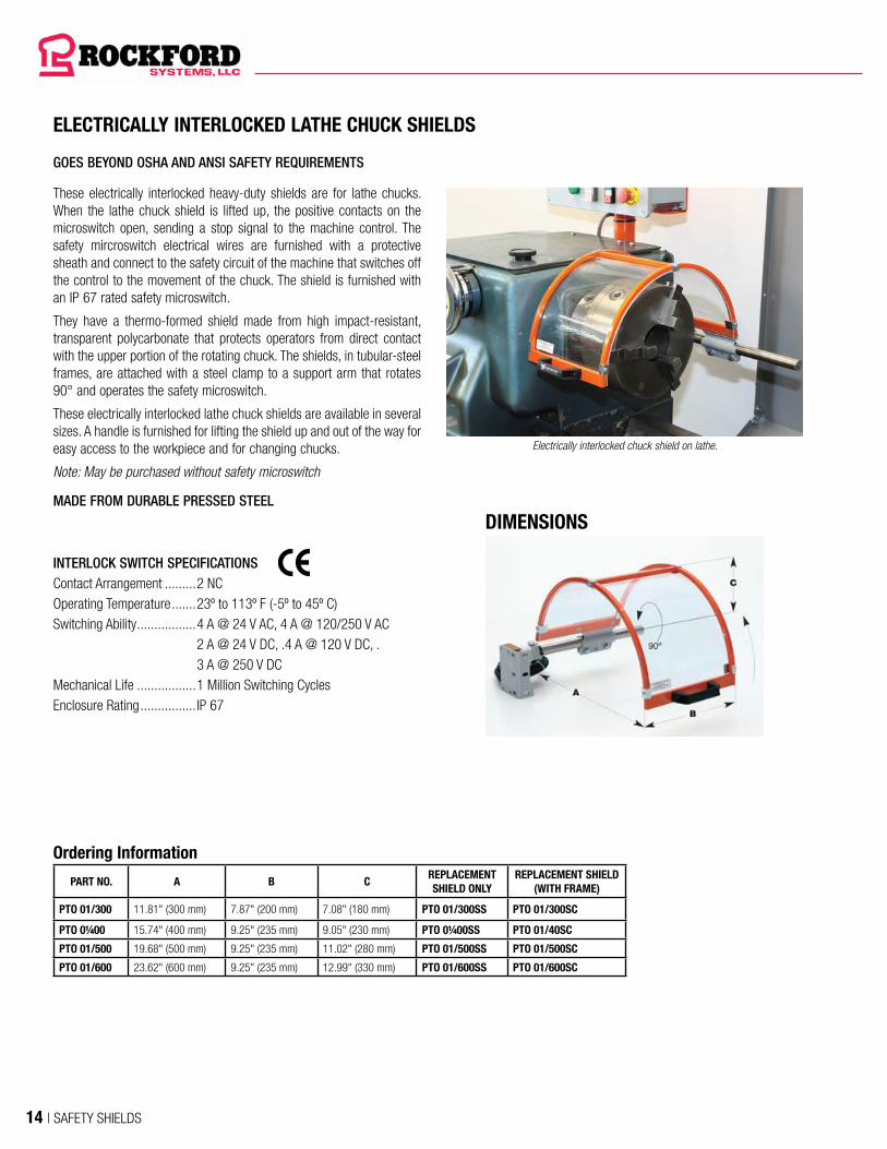
ELECTRICALLY INTERLOCKED LATHE CHUCK SHIELDS
These electrically interlocked heavy-duty shields are for lathe chucks. When the lathe chuck shield is lifted up, the positive contacts on the microswitch open, sending a stop signal to the machine control. The safety mircroswitch electrical wires are furnished with a protective sheath and connect to the safety circuit of the machine that switches off the control to the movement of the chuck. The shield is furnished with an IP 67 rated safety microswitch.
They have a thermo-formed shield made from high impact-resistant, transparent polycarbonate that protects operators from direct contact with the upper portion of the rotating chuck. The shields, in tubular-steel frames, are attached with a steel clamp to a support arm that rotates 90° and operates the safety microswitch.
These electrically interlocked lathe chuck shields are available in several sizes. A handle is furnished for lifting the shield up and out of the way for easy access to the workpiece and for changing chucks.
Note: May be purchased without safety microswitch
MADE FROM DURABLE PRESSED STEEL
INTERLOCK SWITCH SPECIFICATIONSContact Arrangement .........2 NCOperating Temperature .......23º to 113º F (-5º to 45º C)Switching Ability ................. 4 A @ 24 V AC, 4 A @ 120/250 V AC
2 A @ 24 V DC, .4 A @ 120 V DC, . 3 A @ 250 V DC
Mechanical Life .................1 Million Switching CyclesEnclosure Rating ................IP 67
GOES BEYOND OSHA AND ANSI SAFETY REQUIREMENTS
Electrically interlocked chuck shield on lathe.
Ordering Information
PART NO. A B CREPLACEMENT SHIELD ONLY
REPLACEMENT SHIELD (WITH FRAME)
PTO 01/300 11.81" (300 mm) 7.87" (200 mm) 7.08" (180 mm) PTO 01/300SS PTO 01/300SC
PTO 0¼00 15.74" (400 mm) 9.25" (235 mm) 9.05" (230 mm) PTO 0¼00SS PTO 01/40SC
PTO 01/500 19.68" (500 mm) 9.25" (235 mm) 11.02" (280 mm) PTO 01/500SS PTO 01/500SC
PTO 01/600 23.62" (600 mm) 9.25" (235 mm) 12.99" (330 mm) PTO 01/600SS PTO 01/600SC
DIMENSIONS
14 | SAFETY SHIELDS

ELECTRICALLY INTERLOCKED LATHE CHUCK SHIELDS (CONTINUED)
These electrically interlocked heavy-duty shields are for lathe chucks. When the lathe chuck shield is lifted up, the positive contacts on the microswitch open, sending a stop signal to the machine control. The safety mircroswitch electrical wires are furnished with a protective sheath and connect to the safety circuit of the machine that switches off the control to the movement of the chuck. The shield is furnished with an IP 67 rated safety microswitch.
They have a thermo-formed shield made from high impact-resistant, transparent polycarbonate that protects operators from direct contact with the upper portion of the rotating chuck. The shields, in tubular-steel frames, are attached with a steel clamp to a support arm that rotates 90° and operates the safety microswitch.
These electrically interlocked lathe chuck shields are available in several sizes. A handle is furnished for lifting the shield up and out of the way for easy access to the workpiece and for changing chucks.
Note: May be purchased without safety microswitch
Ordering InformationPART NO. Ø A B C D E F G
PTO 20/40015.74"-19.68"(400-500 mm)
17.71"(450 mm)
16.92"(430 mm)
25.78"(655 mm)
18.89"(480 mm)
13.77"(350 mm)
4.92"(125 mm)
11.02"-21.26"(280-540 mm)
PTO 20/60023.62"-27.55"(600-700 mm)
17.71"(450 mm)
20.47"(520 mm)
33.66"(855 mm)
25.19"(640 mm)
16.92"(430 mm)
5.90"(150 mm)
12.59"-29.13"(320-740 mm)
PTO 20/80031.49"-35.43"(800-900 mm)
17.71"(450 mm)
25.19"(640 mm)
41.93"(1,065 mm)
31.49"(800 mm)
20.86"(530 mm)
7.08"(180 mm)
14.56"-37.40"(370-950 mm)
PTO 20/400, PTO 20/600, & PTO 20/800
A
C
D
E
FGØ
B
Max. Dimensions H= A + 15.74" (400 mm)
5.90"-11.81" (150-300 mm)
5.90"-23.62"
(150-600 mm)
Rang
e
A + 6.
69"
(170 m
m)
ELECTRICALLY INTERLOCKED HEAVY-DUTY SHIELDS
SAFETY SHIELDS | 15

Ordering InformationPART NO. A B C D E F G H I
PTO 22/08021.65"(550 mm)
39.37"(1,000 mm)
39.37"(1,000 mm)
20.39"(518 mm)
11.10"(282 mm)
31.49"(800 mm)
11.81"(300 mm)
15.35"-23.22"(390-590 mm)
36.61"-58.66"(930-1,490 mm)
PTO 22/12021.65"(550 mm)
59.05"(1,500 mm)
55.11"(1,400 mm)
36.14"(918 mm)
11.10"(282 mm)
47.24"(1,200 mm)
11.81"(300 mm)
15.35"-23.22"(390-590 mm)
36.61"-58.66"(930-1,490 mm)
G
H
A
E
CI
DB
F
ELECTRICALLY INTERLOCKED LATHE CHUCK SHIELDS (CONTINUED)
Ordering InformationPART NO. A B C D E F G H I
PTO 21/08021.65"(550 mm)
39.37"(1,000 mm)
39.37"(1,000 mm)
20.39"(518 mm)
11.10"(282 mm)
31.49"(800 mm)
11.81"(300 mm)
15.35"-23.22"(390-590 mm)
36.61"-58.66"(930-1,490 mm)
PTO 21/12021.65"(550 mm)
59.05"(1,500 mm)
55.11"(1,400 mm)
36.14"(918 mm)
11.10"(282 mm)
47.24"(1,200 mm)
11.81"(300 mm)
15.35"-23.22"(390-590 mm)
36.61"-58.66"(930-1,490 mm)
G
H
A
E
CI
DB
F
16 | SAFETY SHIELDS

These are electrically interlocked heavy-duty crosslide/carriage travel shields. When the shield is swung out of position, the positive contacts on the microswitch open, sending a stop signal to the machine control. The safety mircroswitch electrical wires are furnished with a protective sheath and connect to the safety circuit of the machine that switches off the control to the movement of the chuck. The shield is furnished with an IP 67 rated safety microswitch.
The shields consist of a high impact-resistant, transparent polycarbonate front panel with an aluminum top plate that provides operator protection from flying chips and coolant. The adjustable shield attaches to tubular-steel arms that provide additional adjustability at the joint and steel base. The steel base which houses the safety microswitch mounts to the backside of the horizontal carriage of the machine.
These electrically interlocked crosslide/carriage travel lathe shields are available in different sizes. Because the shield, arms, and base are adjustable, the shield can be positioned for maximum protection during operation and can be swung out of the way for easy access to the workpiece and tooling.
Note: May be purchased without safety microswitch
GOES BEYOND OSHA AND ANSI SAFETY REQUIREMENTS
ELECTRICALLY INTERLOCKED CROSSLIDE/CARRIAGE TRAVEL LATHE SHIELDS
INTERLOCK SWITCH SPECIFICATIONSContact Arrangement .........2 NCOperating Temperature .......23º to 113º F (-5º to 45º C)Switching Ability ................. 4 A @ 24 V AC, 4 A @ 120/250 V AC
2 A @ 24 V DC, .4 A @ 120 V DC, .3 A @ 250 V DC
Mechanical Life .................1 Million Switching CyclesEnclosure Rating ................IP 67
DIMENSIONS
Ordering Information
PART NO. A B CREPLACEMENT
SHIELD
PTO 10/350 13.77" (350 mm) 11.81" (300 mm) 11.02" (280 mm) PTO 10/350SC
PTO 10/435 15.74" (400 mm) 13.77" (350 mm) 12.20" (310 mm) PTO 10/435SC
MADE FROM DURABLE PRESSED STEEL
ELECTRICALLY INTERLOCKED HEAVY-DUTY SHIELDS
SAFETY SHIELDS | 17

SEMICIRCULAR SHIELDThese are electrically interlocked heavy-duty shields for vertical milling machines with two (2) safety microswitch locations. When the shield is swung out of position at either safety microswitch location, the positive contacts on the microswitch open, sending a stop signal to the machine control. The safety microswitch electrical wires are furnished with a protective sheath and connect to the safety circuit of the machine that switches off the control to the movement of the spindle. Shields are furnished with IP 67 rated safety microswitches.
These have a thermo-formed shield made from high impact-resistant, transparent polycarbonate that provides operator protection from flying chips and coolant. The shields, in tubular-steel frames, clamp to a support rod that rotates 180° and operates the shield safety microswitch. Tubular-steel arms provide additional adjustability at the joint and steel base. The steel base, which houses a second safety microswitch, can be laterally adjusted from .59" to 7.87" (15 to 200 mm).
These electrically interlocked milling machine shields are available in different sizes and are available as left-mount or right-mount models. Because the shield, arms, and base are adjustable, the shield can be positioned for maximum protection during operation and can be swung out of the way for easy access to the workpiece and tooling.
Note: May be purchased without safety microswitch
GOES BEYOND OSHA AND ANSI SAFETY REQUIREMENTS
ELECTRICALLY INTERLOCKED MILLING MACHINE SHIELDS
Ordering InformationLEFT MOUNT
PART NO.RIGHT MOUNT
PART NO.A B
REPLACEMENT SHIELD ONLY
REPLACEMENT SHIELD W/ FRAME
PFR 01/300/SX PFR 01/300/DX 11.81" (300 mm) 7.87" (200 mm) PFR 01/300SS PFR 01/300SC
PFR 0¼00/SX PFR 01/400/DX 15.74" (400 mm) 9.25" (235 mm) PFR 01/400SS PFR 01/400SC
PFR 01/500/SX PFR 01/500/DX 19.68" (500 mm) 9.25" (235 mm) PFR 01/500SS PFR 01/500SC
PFR 01/600/SX PFR 01/600/DX 23.62" (600 mm) 9.25" (235 mm) PFR 01/600SS PFR 01/600SC
DIMENSIONS
INTERLOCK SWITCH SPECIFICATIONSContact Arrangement ......... Two safety switches—2 NC contacts
per switchOperating Temperature .......23º to 113º F (-5º to 45º C)Switching Ability ................. 4 A @ 24 V AC, 4 A @ 120/250 V AC
2 A @ 24 V DC, .4 A @ 120 V DC, .3 A @ 250 V DC
Mechanical Life .................1 Million Switching CyclesEnclosure Rating ................IP 67
MADE FROM DURABLE PRESSED STEEL
18 | SAFETY SHIELDS

GOES BEYOND OSHA AND ANSI SAFETY REQUIREMENTS
ELECTRICALLY INTERLOCKED MILLING MACHINE SHIELDS (CONTINUED)
ANGLED SHIELDThese electrically interlocked heavy-duty shields are for vertical milling machines. They have two (2) safety microswitch locations. When the shield is swung out of position at either safety microswitch location, the positive contacts on the microswitch open, sending a stop signal to the machine control. The safety microswitch electrical wires are furnished with a protective sheath and connect to the safety circuit of the machine that switches off the control to the movement of the spindle. Shields are furnished with IP 67 rated safety microswitches.
These have a thermo-formed shield made from high impact-resistant, transparent polycarbonate that provides operator protection from flying chips and coolant. The shield has an aluminum upper frame and clamps to a support rod that rotates 180° and operates the shield safety microswitch. Tubular-steel arms provide additional adjustability at the joint and steel base. The steel base, which houses a second safety microswitch, can be laterally adjusted from .59" to 7.87" (15 to 200 mm).
These electrically interlocked milling machine shields are available in different sizes and are available as left-mount or right-mount models. Because the shield, arms, and base are adjustable, the shield can be positioned for maximum protection during operation and can be swung out of the way for easy access to the workpiece and tooling.
Note: May be purchased without safety microswitch
INTERLOCK SWITCH SPECIFICATIONSContact Arrangement ......... Two safety switches—2 NC contacts
per switchOperating Temperature .......23º to 113º F (-5º to 45º C)Switching Ability ................. 4 A @ 24 V AC, 4 A @ 120/250 V AC
2 A @ 24 V DC, .4 A @ 120 V DC, . 3 A @ 250 V DC
Mechanical Life .................1 Million Switching CyclesEnclosure Rating ................IP 67
Ordering InformationShield Type
Left Mount Part No.
Right Mount Part No.
A B C DReplacement Shield Only
Replacement Shield W/ Frame
Angled PFR 02/625/SX PFR 02/625/DX 24.41" (620 mm) 7.87" (200 mm) 6.69" (170 mm) 15.94" (405 mm) PFR 02/625SS PFR 02/625SC
Angled PFR 02/725/SX PFR 02/725/DX 28.54" (725 mm) 11.81" (300 mm) 7.87" (200 mm) 16.92" (430 mm) PFR 02/725SS PFR 02/725SC
Flat PFR 02/625/SPL001 PFR 02/625/SPL001 13.78” (350 mm) 11.81” (300 mm) NA NA NA PBF 10/435SC
Flat PFR 02/625/SPL002 PFR 02/625/SPL002 15.75” (400 mm) 13.78” (350 mm) NA NA NA PBF 10/435SC
DIMENSIONS
Angled Shield Made From Durable Pressed SteelFlat Shield Made From Durable Pressed Steel
ELECTRICALLY INTERLOCKED HEAVY-DUTY SHIELDS
SAFETY SHIELDS | 19
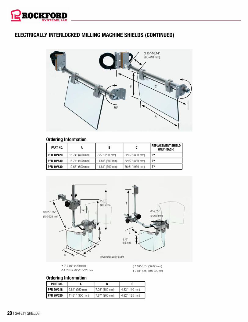
ELECTRICALLY INTERLOCKED MILLING MACHINE SHIELDS (CONTINUED)
Ordering Information
PART NO. A B CREPLACEMENT SHIELD
ONLY (EACH)
PFR 10/420 15.74" (400 mm) 7.87" (200 mm) 32.67" (830 mm) ??
PFR 10/430 15.74" (400 mm) 11.81" (300 mm) 32.67" (830 mm) ??
PFR 10/530 19.68" (500 mm) 11.81" (300 mm) 36.61" (930 mm) ??
A
3.15"-16.14"(80-410 mm)
B
180º
C
Ordering InformationPART NO. A B C
PFR 20/218 9.84" (250 mm) 7.08" (180 mm) 4.33" (110 mm)
PFR 20/320 11.81" (300 mm) 7.87" (200 mm) 4.92" (125 mm)
A
B §
‡
2.16" (55 mm)
0"-9.05"
(0-230 mm)*
0"-9.05" (0-230 mm)
4.33"-12.79" (110-325 mm)§ 1.18"-8.85" (30-225 mm)
‡ 3.93"-8.66" (100-220 mm)
Reversible safety guard
14.17"
(360 mm)
3.93"-8.85"
(100-225 mm)
C
****
***
20 | SAFETY SHIELDS

Single (Right/Left Reversible) Shield
PART NO. A BREPLACEMENT
SHIELD ONLY (EACH)
PMA 10/112 6.29" (160 mm) 5.70" (145 mm) PMA 02/112SC
PMA 10/216 7.87" (200 mm) 7.28" (185 mm) PMA 02/216SC
Double Shield
PART NO. A BREPLACEMENT
SHIELD ONLY (EACH)
PMA 11/112 6.29" (160 mm) 5.70" (145 mm) PMA 02/112SC
PMA 1½16 7.87" (200 mm) 7.28" (185 mm) PMA 02/216SC
These electrically interlocked heavy-duty shields for grinder and tool grinders are ideal for single- and double-wheel grinders. When the shield is swung out of position, the positive contacts on the microswitch open, sending a stop signal to the machine control. The safety microswitch electrical wires are furnished with a protective sheath and connect to the safety circuit of the machine that switches off the control to the movement of the grinding wheel. The shield is furnished with an IP 67 rated safety microswitch.
The multi-adjustable, hexagonal steel arm structure allows easy mounting on the most diverse grinders. A versatile clamp allows horizontal and vertical adjustment of the shield.
Each shield consists of a high impact-resistant, transparent polycarbonate shield with an aluminum profile support and provides operator protection from flying chips and coolant.
GOES BEYOND OSHA AND ANSI SAFETY REQUIREMENTS
ELECTRICALLY INTERLOCKED GRINDER AND TOOL GRINDER SHIELDS
INTERLOCK SWITCH SPECIFICATIONSContact Arrangement ......... 2 NCOperating Temperature .......23º to 113º F (-5º to 45º C)Switching Ability ................. 4 A @ 24 V AC, 4 A @ 120/250 V AC
2 A @ 24 V DC, .4 A @ 120 V DC, . 3 A @ 250 V DC
Mechanical Life .................1 Million Switching CyclesEnclosure Rating ................IP 67
SINGLE SHIELD DOUBLE SHIELD
MADE FROM DURABLE PRESSED STEEL
ELECTRICALLY INTERLOCKED HEAVY-DUTY SHIELDS
SAFETY SHIELDS | 21
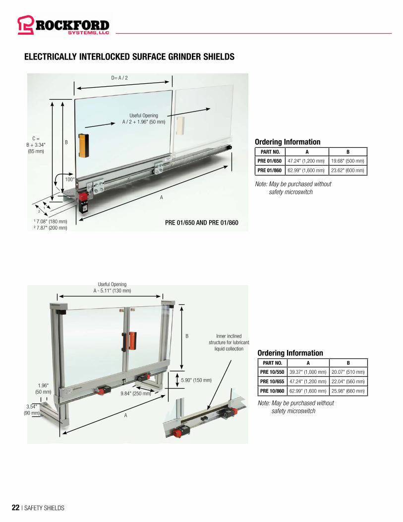
Ordering InformationPART NO. A B
PRE 10/550 39.37" (1,000 mm) 20.07" (510 mm)
PRE 10/655 47.24" (1,200 mm) 22.04" (560 mm)
PRE 10/860 62.99" (1,600 mm) 25.98" (660 mm)
A
B
5.90" (150 mm)
Inner inclined structure for lubricant
liquid collection
Useful OpeningA - 5.11" (130 mm)
9.84" (250 mm)
1.96"(50 mm)
3.54"(90 mm)
ELECTRICALLY INTERLOCKED SURFACE GRINDER SHIELDS
PRE 01/650 AND PRE 01/860
A
¹²
¹ 7.08" (180 mm)² 7.87" (200 mm)
D= A / 2
Useful OpeningA / 2 + 1.96" (50 mm)
B
100°
C =B + 3.34"(85 mm)
Ordering InformationPART NO. A B
PRE 01/650 47.24" (1,200 mm) 19.68" (500 mm)
PRE 01/860 62.99" (1,600 mm) 23.62" (600 mm)
Note: May be purchased without safety microswitch
Note: May be purchased without safety microswitch
22 | SAFETY SHIELDS
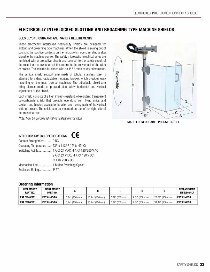
These electrically interlocked heavy-duty shields are designed for slotting and broaching type machines. When the shield is swung out of position, the positive contacts on the microswitch open, sending a stop signal to the machine control. The safety microswitch electrical wires are furnished with a protective sheath and connect to the safety circuit of the machine that switches off the control to the movement of the slide or broach. The shield is furnished with an IP 67 rated safety microswitch.
The vertical shield support arm made of tubular stainless steel is attached to a depth-adjustable mounting bracket which provides easy mounting on the most diverse machines. The adjustable shield-arm fixing clamps made of pressed steel allow horizontal and vertical adjustment of the shield.
Each shield consists of a high impact-resistant, oil-resistant, transparent polycarbonate shield that protects operators from flying chips and coolant, and hinders access to the alternate moving parts of the vertical slide or broach. The shield can be mounted on the left or right side of the machine base.
Note: May be purchased without safety microswitch
GOES BEYOND OSHA AND ANSI SAFETY REQUIREMENTS
ELECTRICALLY INTERLOCKED SLOTTING AND BROACHING TYPE MACHINE SHIELDS
INTERLOCK SWITCH SPECIFICATIONSContact Arrangement ......... 2 NCOperating Temperature .......23º to 113º F (-5º to 45º C)Switching Ability ................. 4 A @ 24 V AC, 4 A @ 120/250 V AC
2 A @ 24 V DC, .4 A @ 120 V DC, .3 A @ 250 V DC
Mechanical Life .................1 Million Switching CyclesEnclosure Rating ................IP 67
Ordering InformationLEFT MOUNT
PART NO.RIGHT MOUNT
PART NO.A B C D E
REPLACEMENT SHIELD ONLY
PST 0½40/SX PST 0½40/DX 15.74" (400 mm) 15.74" (400 mm) 7.87" (200 mm) 9.84" (250 mm) 23.62" (600 mm) PST 0½40SS
PST 0½60/SX PST 0½60/DX 15.74" (400 mm) 15.74" (400 mm) 7.87" (200 mm) 9.84" (250 mm) 31.49" (800 mm) PST 0½60SS
MADE FROM DURABLE PRESSED STEEL
ELECTRICALLY INTERLOCKED HEAVY-DUTY SHIELDS
SAFETY SHIELDS | 23

UNGUARDED DRILL PRESS
SAFEGUARDED DRILL PRESS
ROTATING MEMBERS AND TOOLS
Part No. KSC-046
ALWAYS wear proper personal protective equipment when operating this machine.This sign does not cover all dangers that could happen while operating this machine.
Do Not Remove or Cover This Sign – See Back For Mounting Instructions
You are exposed to moving machine parts that can crush, dismember and cause death. DO NOT operate this machine without shield(s) in place. NEVER place your fingers, hands or any part of your body on or near the rotating parts of this machine. NEVER operate this machine with loose clothing, jewelry, or unrestrained long hair.
FAILURE to obey will result in loss of fingers or limbs, or could cause death.
FLYING PARTS
You are exposed to moving machine parts that can cause eye or bodily injury dueto hazardous flying chips, sparks, andcoolant splash.
NEVER operate this machinery without proper eye and body protection. FAILURE to obey will result in eye injury or severe personal injury.
Danger Sign
Drill Shield
Combination Disconnect Switch, Motor Starter and Emergency Stop
Precautions Sign
24 | SAFETY SHIELDS
ELECTRICALLY INTERLOCKED HEAVY-
DUTY DRILL PRESS SHIELDS
(PAGES 9-12)
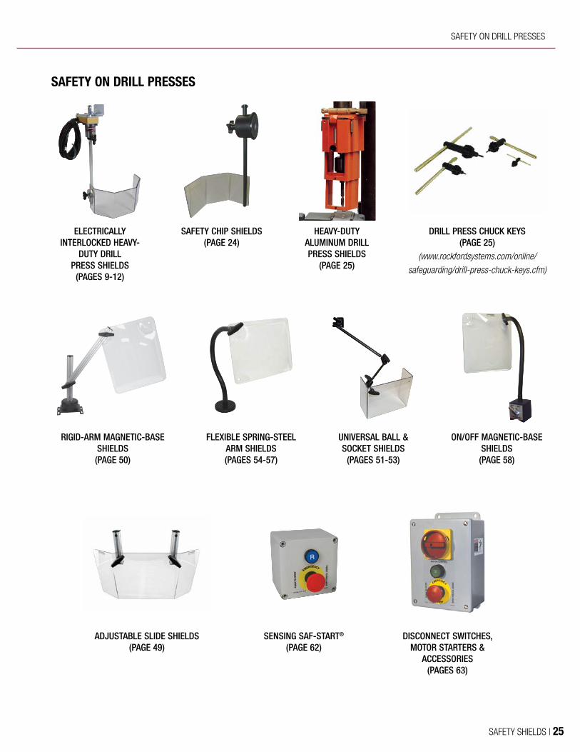
RIGID-ARM MAGNETIC-BASE SHIELDS (PAGE 50)
ON/OFF MAGNETIC-BASE SHIELDS (PAGE 58)
ADJUSTABLE SLIDE SHIELDS (PAGE 49)
DISCONNECT SWITCHES, MOTOR STARTERS &
ACCESSORIES (PAGES 63)
UNIVERSAL BALL & SOCKET SHIELDS
(PAGES 51-53)
SAFETY CHIP SHIELDS (PAGE 24)
HEAVY-DUTY ALUMINUM DRILL PRESS SHIELDS
(PAGE 25)
FLEXIBLE SPRING-STEEL ARM SHIELDS (PAGES 54-57)
SENSING SAF-START®
(PAGE 62)
DRILL PRESS CHUCK KEYS(PAGE 25)
(www.rockfordsystems.com/online/safeguarding/drill-press-chuck-keys.cfm)
SAFETY ON DRILL PRESSES
SAFETY ON DRILL PRESSES
SAFETY SHIELDS | 25
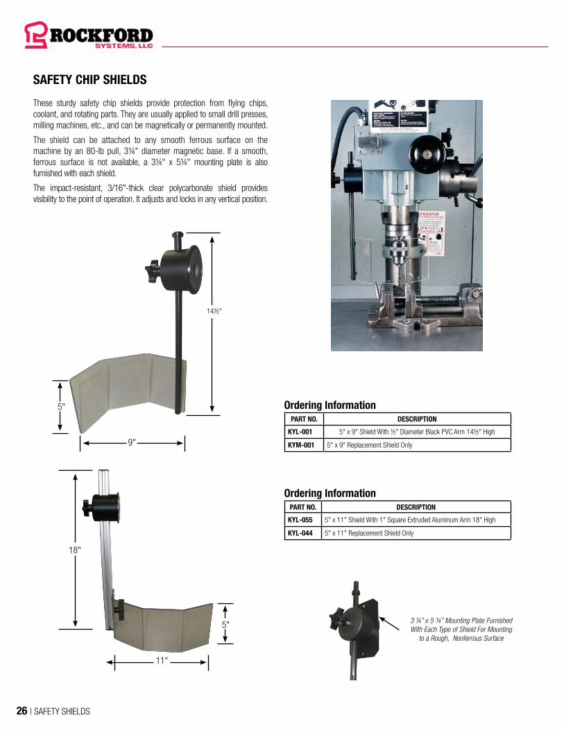
SAFETY CHIP SHIELDS
These sturdy safety chip shields provide protection from flying chips, coolant, and rotating parts. They are usually applied to small drill presses, milling machines, etc., and can be magnetically or permanently mounted.
The shield can be attached to any smooth ferrous surface on the machine by an 80-lb pull, 3¼" diameter magnetic base. If a smooth, ferrous surface is not available, a 3¼" x 5¼" mounting plate is also furnished with each shield.
The impact-resistant, 3/16"-thick clear polycarbonate shield provides visibility to the point of operation. It adjusts and locks in any vertical position.
3 ¼” x 5 ¼” Mounting Plate Furnished With Each Type of Shield For Mounting
to a Rough, Nonferrous Surface
14½"
5"
9"
18"
5"
11"
Ordering InformationPART NO. DESCRIPTION
KYL-001 5" x 9" Shield With ½" Diameter Black PVC Arm 14½" High
KYM-001 5" x 9" Replacement Shield Only
Ordering InformationPART NO. DESCRIPTION
KYL-055 5" x 11" Shield With 1" Square Extruded Aluminum Arm 18" High
KYL-044 5" x 11" Replacement Shield Only
26 | SAFETY SHIELDS

HEAVY-DUTY ALUMINUM DRILL PRESS SHIELDS
These cast-aluminum drill press shields are furnished with a standard 1¾" bore. The user can bore this shield to a size up to 3½" for attaching to the quill of a machine.
This shield is available in 2-tier or 3-tier models which provides 3" to 6" travel of the drill press.
The top of the holder attaches to the quill of the drill press. The shields are open in the back. The bottom section has a clear panel for visibility.
For changing chucks or drill bits, the 2- or 3-tier section can be swung forward and upward out of the way. Also available are shields with a side hinge that swing to the left side.
3-tier shield shown in machining position.
4½"
7¼"
10½"
Min. Max.
6"
10½"
Min. Max.
Front hinge shield shown open for tool change.
1¾" diameter;User to Bore to Size up to 3½"
Dimensions of Part No. DZS-001
Dimensions of Part No. DZS-005
Ordering InformationPART NO. DESCRIPTION
DZS-001 3-Tier Front Hinge 4½" Min; 10½" Max; 6" Stroke; Max Chuck Diameter 2½"
DZS-003 2-Tier Front Hinge 45⁄16" Min; 7" Max; 211⁄16" Stroke; Max Chuck Diameter 2¾"
DZS-004 2-Tier Front Hinge 6" Min; 10½" Max; 4½" Stroke; Max Chuck Diameter 2¾"
DZS-005 2-Tier Side Hinge 6" Min; 10½" Max; 4½" Stroke; Max Chuck Diameter 2¾"
DZS-006 3-Tier Side Hinge 4½" Min; 10½" Max; 6" Stroke; Max Chuck Diameter 2½"
DZS-002 Replacement Polycarbonate Window
Spring-loaded/self-ejecting drill press chuck keys are available to fit a wide variety of chucks.Visit www.rockfordsystems.com/keys
SPRING-LOADED/SELF-EJECTING DRILL PRESS CHUCK KEYS
SAFETY ON DRILL PRESSES
SAFETY SHIELDS | 27

UNGUARDED LATHE
SAFEGUARDED LATHEMagnetic-Base Shield
Crosslide-Travel ShieldChuck ShieldEmergency-Stop
ButtonDanger and Precautions Sign
Disconnect Switch and Motor Starter
Electronic Motor Brake
28 | SAFETY SHIELDS

ELECTRICALLY INTERLOCKED HEAVY-DUTY LATHE SHIELDS
(PAGES 8-21)
RIGID-ARM MAGNETIC-BASE
SHIELDS (PAGE 50)
ON/OFF MAGNETIC-BASE SHIELDS (PAGE 58)
TRANSPARENT LATHE CHUCK SHIELDS
(PAGE 32)
SENSING SAF-START®
(PAGE 62)LATHE MOUNTING
BRACKETS (PAGE 33)
DISCONNECT SWITCHES, MOTOR STARTERS & ACCESSORIES
(PAGES 63)
FLEXIBLE SPRING-STEEL ARM SHIELDS
(PAGES 54-57)
UNIVERSAL BALL & SOCKET SHIELDS
(PAGES 52-53)
SMALL STEEL LATHE CHUCK SHIELDS
(PAGE 30)
LARGE STEEL LATHE CHUCK SHIELDS
(PAGE 31)
ELECTRICALLY INTERLOCKED HEAVY-DUTY
CROSSLIDE/CARRIAGE TRAVEL LATHE SHIELDS
(PAGE 15)
SLIDING LATHE SHIELDS (PAGE 28)
CROSSLIDE-TRAVEL LATHE SHIELDS
(PAGE 29)
LATHE CHUCK WRENCHES (PAGES 34-35)
SAFETY ON LATHES
SAFETY ON LATHES
SAFETY SHIELDS | 29

SLIDING LATHE SHIELDS
Ordering InformationPART NO. A B CHUCK DIAMETER REPLACEMENT POLYCARBONATE WINDOW
MAJ-700 26" 21" 28" MAW-001
MAJ-800 27¼" 23" 32" MAW-002
MAJ-100 29½" 27" 40" MAW-003
MAJ-120 33¼" 30¾" 48" MAW-004
These heavy-duty sliding lathe shields are furnished in four different sizes. They are constructed of high quality, 12-gauge reinforced steel with a polycarbonate window. These shields are available for operator protection on large standard lathes, CNC machines, and OD grinders.
The shields are designed to fit lathes with chucks up to 48" in diameter. Four adjustable flanged mounting posts are provided for easy mounting. These posts are used to securely mount the shield’s ball-bearing carriage to the top of the headstock, as illustrated (mounting hardware not included). This means the posts can be attached without interfering with any part of the equipment housed within the headstock.
These sliding shields slide out-of-the-way over the headstock, allowing the operator access to the point of operation for loading and unloading workpieces, changing tooling, changing chucks, removing swarf, etc. Each shield has approximately 22" of travel.
When ordering these sliding shields, check lathe dimensions and reference drawings. Special sizes are available on request.
DIMENSIONS
Adjustable From 2"–12"
A
B
Window
20"
15¾" Ctrs.
12" Max. Can Be Cut to Length as Required
Shield slid into position. Machine is ready for machining workpiece.
30 | SAFETY SHIELDS

CROSSLIDE-TRAVEL LATHE SHIELDS
These lathe shields mount on and travel with the crosslide for protection when machining long workpieces. The 18-gauge reinforced steel structure provides protection from flying chips and coolant. The high-impact-resistant polycarbonate window permits visibility into the point of operation. The front portion of the shield hinges up for access. These shields are ideal for lathes with long beds. Special sizes are available on request.
MOUNTING BRACKETS ARE SOLD SEPARATELY—SEE PAGE 33
Mounting Rod
Hinges up for access.
Support Rod
LXS-650 Mounting Bracket
E
A
4"
D
CB
HINGE
DIMENSIONS
Window
Ordering InformationPART NO. A B C D E
TXS-100 17" 8" 10" 12" 12"
TXS-200 23" 11" 12" 14½" 13¾"
TXW-000 Replacement Polycarbonate Window
Shield travels with the crosslide for operator protection.
SAFETY ON LATHES
SAFETY SHIELDS | 31
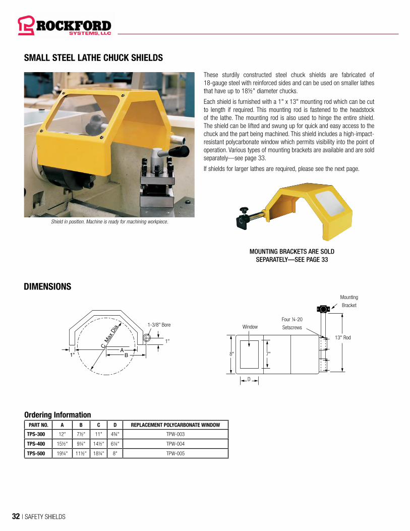
SMALL STEEL LATHE CHUCK SHIELDS
These sturdily constructed steel chuck shields are fabricated of 18-gauge steel with reinforced sides and can be used on smaller lathes that have up to 18½" diameter chucks.
Each shield is furnished with a 1" x 13" mounting rod which can be cut to length if required. This mounting rod is fastened to the headstock of the lathe. The mounting rod is also used to hinge the entire shield. The shield can be lifted and swung up for quick and easy access to the chuck and the part being machined. This shield includes a high-impact-resistant polycarbonate window which permits visibility into the point of operation. Various types of mounting brackets are available and are sold separately—see page 33.
If shields for larger lathes are required, please see the next page.
MOUNTING BRACKETS ARE SOLD SEPARATELY—SEE PAGE 33
DIMENSIONS
Shield in position. Machine is ready for machining workpiece.
Ordering InformationPART NO. A B C D REPLACEMENT POLYCARBONATE WINDOW
TPS-300 12" 7½" 11" 4¾" TPW-003
TPS-400 15½" 9¼" 14½" 6¼" TPW-004
TPS-500 19¼" 11½" 18¼" 8" TPW-005
1-3/8" Bore
13" Rod
8"
Window
7"
D
Mounting
Bracket
Four ¼-20
Setscrews
1"
32 | SAFETY SHIELDS
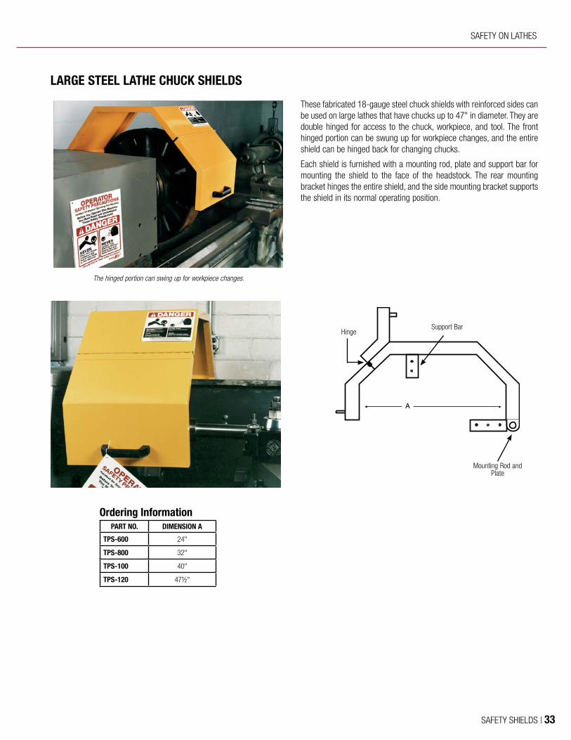
These fabricated 18-gauge steel chuck shields with reinforced sides can be used on large lathes that have chucks up to 47" in diameter. They are double hinged for access to the chuck, workpiece, and tool. The front hinged portion can be swung up for workpiece changes, and the entire shield can be hinged back for changing chucks.
Each shield is furnished with a mounting rod, plate and support bar for mounting the shield to the face of the headstock. The rear mounting bracket hinges the entire shield, and the side mounting bracket supports the shield in its normal operating position.
LARGE STEEL LATHE CHUCK SHIELDS
13-3/4"
A
The hinged portion can swing up for workpiece changes.
Support Bar
Mounting Rod and Plate
Hinge
Ordering InformationPART NO. DIMENSION A
TPS-600 24"
TPS-800 32"
TPS-100 40"
TPS-120 47½"
SAFETY ON LATHES
SAFETY SHIELDS | 33

3-jaw chuck lathe with shield held in position by bracket Type B.
These quality-constructed lathe chuck shields have a semicircular shape made from high-impact-resistant transparent polycarbonate. The shields themselves are attached to a 1" zinc-plated extension tube. This tube is inserted into one of the mounting brackets described on the next page. The shield assembly does not include the mounting bracket.
The semicircular shield covers half the circumference of the lathe chuck because it is mounted an equal distance from the chuck center.
Access to the chuck and workpiece is quick and easy. The shield is lifted up and out of the way for the operator.
The shield size depends on the center height of the lathe and the diameter of the chuck. On lathes with a center height up to 7", there is a small variation in diameter between the 3- and 4-jaw chucks; therefore, one size shield will do the job.
On lathes with a center height in excess of 7", there is a greater variation in diameter between the chucks; therefore, it is advisable to use two different size shields to provide adequate protection.
TRANSPARENT LATHE CHUCK SHIELDS
B
A M
ax. D
ia.
C
Type B Bracket
D E
Type B2 Bracket
1" Rod
Support Assembly
DIMENSIONS
High-Impact-Resistant Clear Polycarbonate Swings up for
Access
Optional Mounting Bracket With Electrical Safety Interlock
Ordering InformationPART NO. A B C D E REPLACEMENT SHIELD
LXS-300 10" 12" 7" 6½" 10" LXS-301
LXS-400 14" 15½" 8½" 7¾" 13" LXS-401
LXS-500 18" 19½" 10½" 7¾" 13" LXS-501
LXS-600 23½" 24¼" 12¾" 7¾" 13" LXS-601
LXS-700 26" 28" 14¾" 7¾" 13" LXS-701
MOUNTING BRACKETS ARE SOLD SEPARATELY—SEE FOLLOWING PAGE.
34 | SAFETY SHIELDS
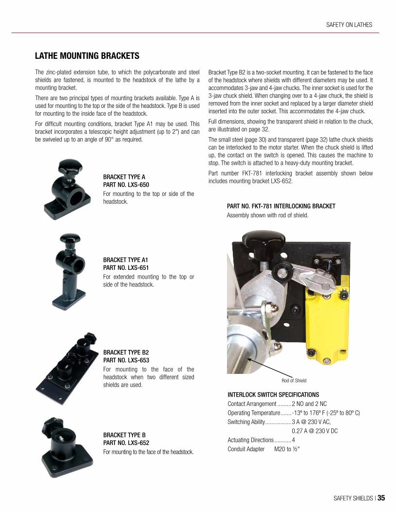
LATHE MOUNTING BRACKETS
The zinc-plated extension tube, to which the polycarbonate and steel shields are fastened, is mounted to the headstock of the lathe by a mounting bracket.
There are two principal types of mounting brackets available. Type A is used for mounting to the top or the side of the headstock. Type B is used for mounting to the inside face of the headstock.
For difficult mounting conditions, bracket Type A1 may be used. This bracket incorporates a telescopic height adjustment (up to 2") and can be swiveled up to an angle of 90° as required.
Bracket Type B2 is a two-socket mounting. It can be fastened to the face of the headstock where shields with different diameters may be used. It accommodates 3-jaw and 4-jaw chucks. The inner socket is used for the 3-jaw chuck shield. When changing over to a 4-jaw chuck, the shield is removed from the inner socket and replaced by a larger diameter shield inserted into the outer socket. This accommodates the 4-jaw chuck.
Full dimensions, showing the transparent shield in relation to the chuck, are illustrated on page 32.
The small steel (page 30) and transparent (page 32) lathe chuck shields can be interlocked to the motor starter. When the chuck shield is lifted up, the contact on the switch is opened. This causes the machine to stop. The switch is attached to a heavy-duty mounting bracket.
Part number FKT-781 interlocking bracket assembly shown below includes mounting bracket LXS-652.
BRACKET TYPE A PART NO. LXS-650For mounting to the top or side of the headstock.
BRACKET TYPE A1 PART NO. LXS-651For extended mounting to the top or side of the headstock.
BRACKET TYPE B2 PART NO. LXS-653For mounting to the face of the headstock when two different sized shields are used.
BRACKET TYPE B PART NO. LXS-652For mounting to the face of the headstock.
PART NO. FKT-781 INTERLOCKING BRACKET Assembly shown with rod of shield.
Rod of Shield
INTERLOCK SWITCH SPECIFICATIONSContact Arrangement ......... 2 NO and 2 NCOperating Temperature .......-13º to 176º F (-25º to 80º C)Switching Ability ................. 3 A @ 230 V AC,
0.27 A @ 230 V DCActuating Directions ...........4Conduit Adapter M20 to ½"
SAFETY ON LATHES
SAFETY SHIELDS | 35

STANDARD SIZE LATHE CHUCK WRENCHES
One of the most common accidents on lathes or other machines involves a chuck wrench or key which is thrown from the chuck. This happens when someone forgets to remove the wrench from the chuck before the machine is turned on.
The spring-loaded or self-ejecting chuck wrenches on pages 34 and 35 can be used on lathes or other machines equipped with manually adjusted chucks. The spring-loaded sleeve ejects the wrench from the chuck after each use. These wrenches are engineered and designed to provide proper loads for self-removal of the wrench weight.
Ordering Information
PART NO.NOMINAL
SIZEACTUAL
SIZEBAR
DIAMETEROVERALL
DIAMETERHANDLE LENGTH
CW-SM0281-S 9⁄32" SQ .271" ¾" 1.050" 5½"
CW-SM0312-S 5⁄16" SQ .303" ¾" 1.050" 5½"
CW-SM0375-S 3⁄8" SQ .365" ¾" 1.050" 5½"
CW-SM0438-S 7⁄16" SQ .427" ¾" 1.050" 5½"
CW-SM0500-S ½" SQ .490" ¾" 1.050" 5½"
CW-SM0563-S 9⁄16" SQ .552" 15⁄16" 1.315" 9½"
CW-SM0625-S 5⁄8" SQ .615" 15⁄16" 1.315" 9½"
CW-SM0688-S 11⁄16" SQ .678" 15⁄16" 1.315" 9½"
CW-SM0750-S ¾" SQ .740" 15⁄16" 1.315" 9½"
CW-HM0500-S ½" HEX .490" ¾" 1.050" 5½"
CW-HM0625-S 5⁄8" HEX .615" ¾" 1.050" 9½"
CW-HM0750-S ¾" HEX .740" 15⁄16" 1.315" 9½"
Adjusting the chuck using a spring-loaded chuck wrench.
Handle Length
8" BodySafety Yellow Vinyl-Coated Handle
Spring-Loaded Sleeve Fully Encloses Spring (Sleeve Pushed Up for Photo)
5/8" Engagement Length
Overall Diameter
Bar Diameter
ALL PARTS BLACK OXIDE COATED
36 | SAFETY SHIELDS

LONGER LATHE CHUCK WRENCHES
5/8" Engagement Length
Overall Diameter
Bar Diameter
Adjusting the chuck using a long-handled spring-loaded chuck wrench.
The 18" handle can be slid into position and locked in place with the thumb screw.
Thumb Screw
18" Sliding Handle
18" Sliding Handle
10" Body
Spring-Loaded Sleeve Fully Encloses Spring
Ordering Information
PART NO.NOMINAL
SIZEACTUAL
SIZEBAR
DIAMETEROVERALL
DIAMETER
CW-SM0281-L 9⁄32" SQ .271" ¾" 1.050"
CW-SM0312-L 5⁄16" SQ .303" ¾" 1.050"
CW-SM0375-L 3⁄8" SQ .365" ¾" 1.050"
CW-SM0438-L 7⁄16" SQ .427" ¾" 1.050"
CW-SM0500-L ½" SQ .490" ¾" 1.050"
CW-SM0563-L 9⁄16" SQ .552" 15⁄16" 1.315"
CW-SM0625-L 5⁄8" SQ .615" 15⁄16" 1.315"
CW-SM0688-L 11⁄16" SQ .678" 15⁄16" 1.315"
CW-SM0750-L ¾" SQ .740" 15⁄16" 1.315"
CW-HM0500-L ½" HEX .490" ¾" 1.050"
CW-HM0625-L 5⁄8" HEX .615" ¾" 1.050"
CW-HM0750-L ¾" HEX .740" 15⁄16" 1.315"
ALL PARTS BLACK OXIDE COATED
SAFETY ON LATHES
SAFETY SHIELDS | 37
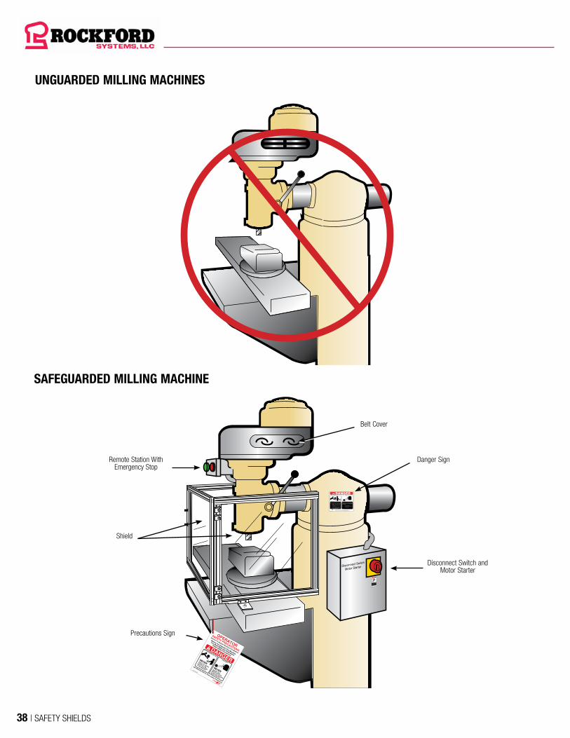
UNGUARDED MILLING MACHINES
SAFEGUARDED MILLING MACHINE
Disconnect Switch
Motor Starter
Can cause serious injury
or death if hand or any part
of body is placed in this
electrical enclosure.
Turn off main power and
lock out the disconnect
switch before opening this
electrical enclosure.
DO NOT REMOVE OR COVER THIS SIGNKST-152
WARNING
Disconnect Switch and Motor Starter
Danger Sign
Belt Cover
Precautions Sign
Shield
Remote Station With Emergency Stop
38 | SAFETY SHIELDS
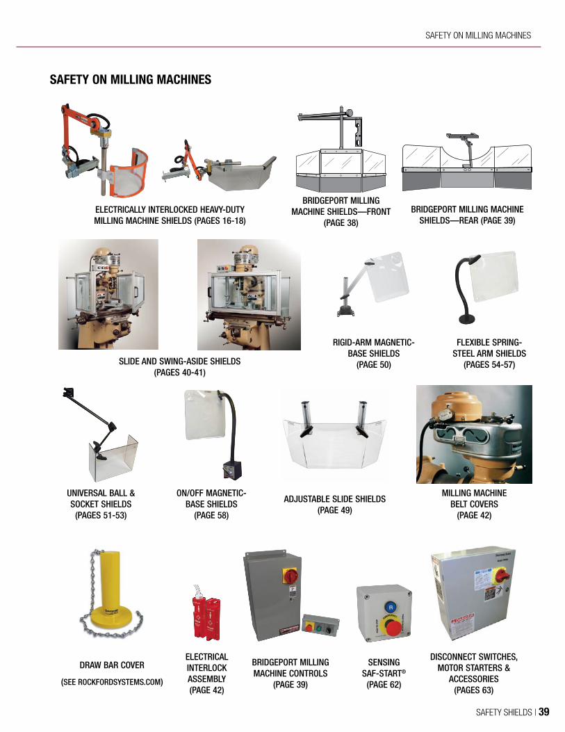
RIGID-ARM MAGNETIC-BASE SHIELDS
(PAGE 50)
ELECTRICALLY INTERLOCKED HEAVY-DUTY MILLING MACHINE SHIELDS (PAGES 16-18)
BRIDGEPORT MILLING MACHINE SHIELDS—FRONT
(PAGE 38)BRIDGEPORT MILLING MACHINE
SHIELDS—REAR (PAGE 39)
SLIDE AND SWING-ASIDE SHIELDS (PAGES 40-41)
FLEXIBLE SPRING-STEEL ARM SHIELDS
(PAGES 54-57)
UNIVERSAL BALL & SOCKET SHIELDS
(PAGES 51-53)
ON/OFF MAGNETIC-BASE SHIELDS
(PAGE 58)
ADJUSTABLE SLIDE SHIELDS (PAGE 49)
MILLING MACHINE BELT COVERS
(PAGE 42)
SENSING SAF-START®
(PAGE 62)
DISCONNECT SWITCHES, MOTOR STARTERS &
ACCESSORIES(PAGES 63)
ELECTRICAL INTERLOCK ASSEMBLY (PAGE 42)
BRIDGEPORT MILLING MACHINE CONTROLS
(PAGE 39)
DRAW BAR COVER
(SEE ROCKFORDSYSTEMS.COM)
SAFETY ON MILLING MACHINES
SAFETY ON MILLING MACHINES
SAFETY SHIELDS | 39

CHIP SHIELDS FOR BRIDGEPORT MILLING MACHINES
These specially designed, quality-constructed shields are ideal for Bridgeport milling machines. They place a barrier between flying chips (swarf), sparks, coolant from the machine, and the operators or other employees in the area. They can be easily moved in or out of position to provide quick tool and part changes.
These shields are quick and easy to install. They attach directly to existing head machine bolts so no additional drilling or tapping is required.
These shields are constructed of high-impact-resistant polycarbonate material. Attached at the bottom of each section of the shield is durable, flexible neoprene material to keep flying chips and swarf contained as the bed moves up and down.
FRONT SHIELDSThe front shield is mounted on a heavy-duty universal steel arm which is used to swing it back into the exact position it was before tool or workpiece changes. The arm is 29" long and has an adjusting knob for raising and lowering the shield. The shield itself can also be used to hold a print.
KYL-019 front chip shield.
19"
4"
5¼"
9¼"9" 9"
15"
4"
9"6"
5¼"
9¼"
Ordering InformationPART NO. DESCRIPTION
KYL-019 9¼" H x 19" W Front Shield With Two 45° Bends
KYL-065 9¼" x 19" Front Replacement Shield Only
Ordering InformationKYL-059 9¼" H x 15" W Front Shield With One 45° Bend and One 90º Bend
40 | SAFETY SHIELDS

REAR SHIELDA rear shield is also available to protect the back area of the milling machine. This shield is easy to install and mounts directly onto the machine frame with a setscrew to hold it in place.
CHIP SHIELDS FOR BRIDGEPORT MILLING MACHINES (CONTINUED)
This control is designed for Bridgeport vertical milling machines that have a table motor. Each milling machine control is housed in a NEMA 12 enclosure that includes a disconnect switch, reversing magnetic main drive motor starter, a control relay for the table motor, and a 100 VA transformer that is generically numbered and wired to terminals. A remote station provides the operator controls consisting of a self-latching red emergency-stop palm button, an illuminated green table motor reset push button, and a main motor reverse/off/forward selector switch. These Bridgeport vertical milling machine controls are available for machines with 230 or 460 V AC and 1 to 3 HP.
BRIDGEPORT VERTICAL MILLING MACHINE CONTROLS
Ordering InformationPART NO. DESCRIPTION
KYL-020 7¼" H x 18" W Rear Shield With Two 45° Bends
KYL-065 7¼" x 18" Rear Replacement Shield Only
Ordering InformationPART NO. DESCRIPTION
BVM-230-1 For 1 HP, 230-V AC Machines
BVM-230-15 For 1.5 HP, 230-V AC Machines
BVM-230-2 For 2 HP, 230-V AC Machines
BVM-230-3 For 3 HP, 230-V AC Machines
BVM-460-1 For 1 HP, 460-V AC Machines
BVM-460-15 For 1.5 HP, 460-V AC Machines
BVM-460-2 For 2 HP, 460-V AC Machines
BVM-460-3 For 3 HP, 460-V AC Machines
18" Rear shield only (front shield not shown).
4"
6"
9"
6"
3¼"
17"
10"8¼"
3½"
SAFETY ON MILLING MACHINES
SAFETY SHIELDS | 41
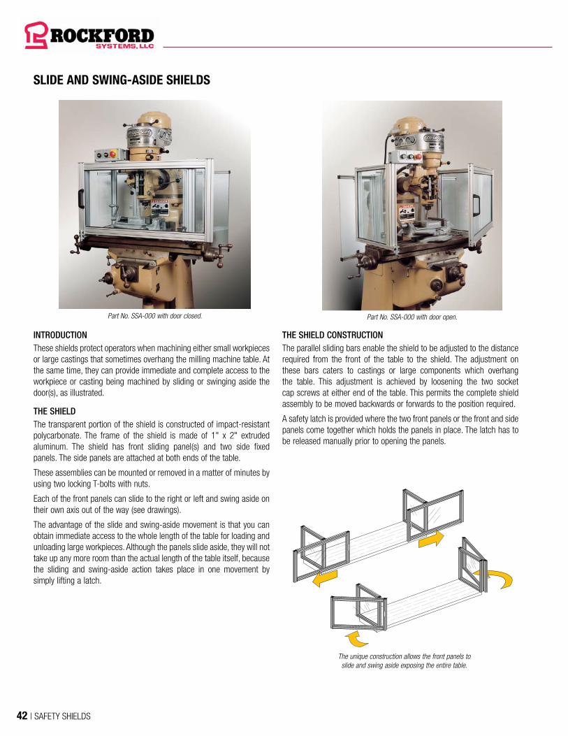
SLIDE AND SWING-ASIDE SHIELDS
Part No. SSA-000 with door closed. Part No. SSA-000 with door open.
The unique construction allows the front panels to slide and swing aside exposing the entire table.
INTRODUCTIONThese shields protect operators when machining either small workpieces or large castings that sometimes overhang the milling machine table. At the same time, they can provide immediate and complete access to the workpiece or casting being machined by sliding or swinging aside the door(s), as illustrated.
THE SHIELDThe transparent portion of the shield is constructed of impact-resistant polycarbonate. The frame of the shield is made of 1" x 2" extruded aluminum. The shield has front sliding panel(s) and two side fixed panels. The side panels are attached at both ends of the table.
These assemblies can be mounted or removed in a matter of minutes by using two locking T-bolts with nuts.
Each of the front panels can slide to the right or left and swing aside on their own axis out of the way (see drawings).
The advantage of the slide and swing-aside movement is that you can obtain immediate access to the whole length of the table for loading and unloading large workpieces. Although the panels slide aside, they will not take up any more room than the actual length of the table itself, because the sliding and swing-aside action takes place in one movement by simply lifting a latch.
THE SHIELD CONSTRUCTIONThe parallel sliding bars enable the shield to be adjusted to the distance required from the front of the table to the shield. The adjustment on these bars caters to castings or large components which overhang the table. This adjustment is achieved by loosening the two socket cap screws at either end of the table. This permits the complete shield assembly to be moved backwards or forwards to the position required.
A safety latch is provided where the two front panels or the front and side panels come together which holds the panels in place. The latch has to be released manually prior to opening the panels.
42 | SAFETY SHIELDS

SLIDE AND SWING-ASIDE SHIELDS (CONTINUED)
There are three sizes of shields available which cover table sizes up to a maximum length of 76". On bed-type milling machines, where the table length is well in excess of 76", it is still possible to use the SSA-300 shield. In many instances, only part of the maximum length of the table is used. If this is the case, the SSA-300 shield would be suitable as long as the longitudinal traverse used does not exceed the maximum length of the shield. For a table length of less than 36", the SSA-000 shield may be used.
These shields have been generously designed to give protection to the operator; this will be noted in dimension H, which gives the height of the shields. Special height panels are available upon request.
The standard shield does not provide protection on the back of the table. The rear shields (below) are used to minimize coolant splash and flying chips that may fly out of the back of the machine.
TableTable Parallel Sliding Bar
L
H
D
AFront view with sliding shields closed
Rear shield assembly on left side of machine column.
*Has one sliding and swing front door **Has two sliding and swing front panels.
End elevation showing shield in maximum forward position.
Ordering Information
PART NO.L–LENGTH OF
TABLE WORK SURFACEH
HEIGHTD
DEPTHA
MAXIMUM ADJUSTMENT
SSA-000* 24"-36" 20" 20" 13"
SSA-200** 36"-56" 20" 20" 13"
SSA-300** 56"-76" 20" 20" 13"
REAR SHIELD ASSEMBLIESThese shield assemblies can be used to protect personnel from swarf and chips at the rear of the table on both sides of the machine column. They can be used on milling machines or other equipment that require these types of shields. The two ¼"-thick polycarbonate panels are mounted to the frame of the machine with mounts (see photo). Each panel has extruded aluminum framing to hold the polycarbonate in place. The mounts are also attached to this frame. The assembly is available in two sizes and includes two shields, one set of mounts, and connectors. Special sizes are available upon request.
Ordering InformationPART NO. DESCRIPTION
SSA-420 24" x 24" Rear Shields With Mounts (Set)
SSA-430 24" x 36" Rear Shields With Mounts (Set)
SAFETY ON MILLING MACHINES
SAFETY SHIELDS | 43

Cover closed. Cover open on model J Bridgeport milling machine.
(Mounted on inside of front panels.)
MILLING MACHINE BELT COVERS
OSHA requires under 29 CFR 1910.219 that all mechanical power-transmission apparatuses on machinery that create a hazard be covered if below a 7-foot level from the floor or working platform. The sheaves and belts on milling machines must be covered to meet this requirement.
These unique patented belt covers are made of durable cast aluminum. The hinged covers are sold in pairs for the right and left sides and are permanently attached to the machine. Spindle speed changes are done quickly and efficiently by simply pulling down the belt cover.
This belt cover is made for Bridgeport model J.
Ordering InformationKYL-021J Model J Belt Cover With Hinges—11" W x 2¾" H x 3⁄8" Thick
ELECTRICAL INTERLOCK ASSEMBLY
MAGNETIC SAFETY SWITCH AND BRACKET ASSEMBLY PART NO. FKT-876 Additional operator safety can be provided by the installation of this magnetic safety switch and bracket assembly.
INTERLOCK SWITCH SPECIFICATIONSContacts ............................ 1 NOOperating Temperature .......14º to 149º F (-10º to 65º C)Rated Current .................... 2 A, fuse externally 1.6 A quick actingRated Voltage ....................250 V ACCable ................................13 ft of prewired 2-conductor flexible cable
44 | SAFETY SHIELDS

UNGUARDED GRINDER SAFEGUARDED GRINDER
Shields
Danger Sign
Disconnect, Motor Starter, and Emergency Stop
Grinder Gauge—Used To Measure Tongue and Work
Rest Openings
ELECTRICALLY INTERLOCKED HEAVY-DUTY BENCH
BUFFER SHIELDS (PAGE 19)
STANDARD-MOUNT GRINDER SHIELDS
(PAGE 45)
BENCH GRINDER SAFETY GAUGE
(PAGE 46)
HEAVY-DUTY SINGLE BUFFER SHIELDS
(PAGE 45)
DOUBLE-WHEEL FLEXIBLE-ARM SHIELDS
(PAGE 44)
SINGLE-WHEEL FLEXIBLE-ARM SHIELDS
(PAGE 44)
SENSING SAF-START®
(PAGE 62)
DISCONNECT SWITCHES, MOTOR STARTERS, AND ACCESSORIES
(PAGES 63)
SAFETY ON BENCH GRINDERS
RIGID-ARM MAGNETIC-BASE SHIELDS
(PAGE 50)
UNIVERSAL BALL & SOCKET SHIELDS
(PAGES 51-53)
SAFETY ON BENCH GRINDERS
SAFETY SHIELDS | 45

DOUBLE- AND SINGLE-WHEEL FLEXIBLE-ARM GRINDER SHIELDS
Double-Wheel Grinder Shield
Single-Wheel Grinder Shield
Bench grinder shields are designed to minimize the debris and hazards associated with bench grinders and buffers. Both double- and single-wheel grinder shields are available.
The double-wheel grinder shield provides protection for both wheels of the grinder with one continuous shield. The durable shield is made of clear, 3/16"-thick polycarbonate and measures 18" x 6". A special shield bracket adds stability to the top of the shield.
The single-wheel grinder shield is made of clear, 3/16"-thick polycarbonate and measures 6" x 6". This sturdy, impact-resistant shield is designed for use when a single wheel needs safeguarding.
The flexible spring-steel arms come in three lengths: 12", 18" and 24".MOUNTING OPTIONSThere are two mounting options for the double- and single-wheel grinder shields.
• Direct-mount base—attaches directly to the grinder table or pedestal
• Magnetic base—3" diameter magnet
If an adequate flat, smooth, ferrous mounting surface is not available, an optional steel mounting plate is available that can be permanently attached to the machine to hold the magnetic base.
DOUBLE-WHEEL GRINDER SHIELDS—18" X 6" FLAT SHIELD
PART NO. DESCRIPTION
KYL-183 12" Direct-Mount Flexible Spring-Steel Arm
KYL-184 18" Direct-Mount Flexible Spring-Steel Arm
KYL-185 24" Direct-Mount Flexible Spring-Steel Arm
KYL-186 12" Magnetic-Mount Flexible Spring-Steel Arm
KYL-187 18" Magnetic-Mount Flexible Spring-Steel Arm
KYL-188 24" Magnetic-Mount Flexible Spring-Steel Arm
KYL-177 18" x 6" Flat Replacement Shield Only
FKT-1072 Flat Mounting Bracket for 18" x 6" Shield
FKT-1106 3½" x 45⁄8" Steel Mounting Plate for Magnetic Base
SINGLE-WHEEL GRINDER SHIELDS—6" X 6" FLAT SHIELD
PART NO. DESCRIPTION
KYL-178 18" Direct-Mount Flexible Spring-Steel Arm
KYL-179 24" Direct-Mount Flexible Spring-Steel Arm
KYL-180 12" Magnetic-Mount Flexible Spring-Steel Arm
KYL-181 18" Magnetic-Mount Flexible Spring-Steel Arm
KYL-182 24" Magnetic-Mount Flexible Spring-Steel Arm
KYL-176 6" x 6" Flat Replacement Shield Only
FKT-1106 3½" x 45⁄8" Steel Mounting Plate for Magnetic Base
Part No. FKT-1106 Steel Mounting Plate
46 | SAFETY SHIELDS

STANDARD-MOUNT GRINDER SHIELDS
HEAVY-DUTY SINGLE BUFFER SHIELDS
These grinder shields are available in various sizes for protection from the swarf of bench or pedestal grinders. The frames are constructed of reinforced fiber nylon or heavy cast aluminum. Each shield is furnished with a threaded support rod. The transparent shield is high-impact-resistant polycarbonate to minimize scratching and provide durability.
These buffer shields are available in various sizes for protection from the swarf of bench or pedestal grinders. The frames are constructed of reinforced fiber nylon or heavy cast aluminum. Each shield is furnished with a threaded support rod. The transparent shield is high-impact-resistant polycarbonate to minimize scratching and provide durability.
Ordering InformationPART NO. DESCRIPTION (EACH SOLD SEPARATELY) REPLACEMENT POLYCARBONATE WINDOW
GWG-201 6¼" H x 5¼" W Shield—Nylon Frame GWW-001
GWG-202 8½" H x 6" W Shield—Nylon Frame GWW-002
GWG-203 12¾" H x 12" W Shield—Aluminum Frame GWW-003
Ordering InformationPART NO. A B
PMA 02/112 6.3" (160 mm) 5.71" (145 mm)
PMA 02/216 7.87" (200 mm) 7.28" (185 mm)
A
B
¹²
5.19"(130 mm)
¹ 1.18" (30 mm) ² 0.98" (25 mm)
SAFETY ON BENCH GRINDERS
SAFETY SHIELDS | 47
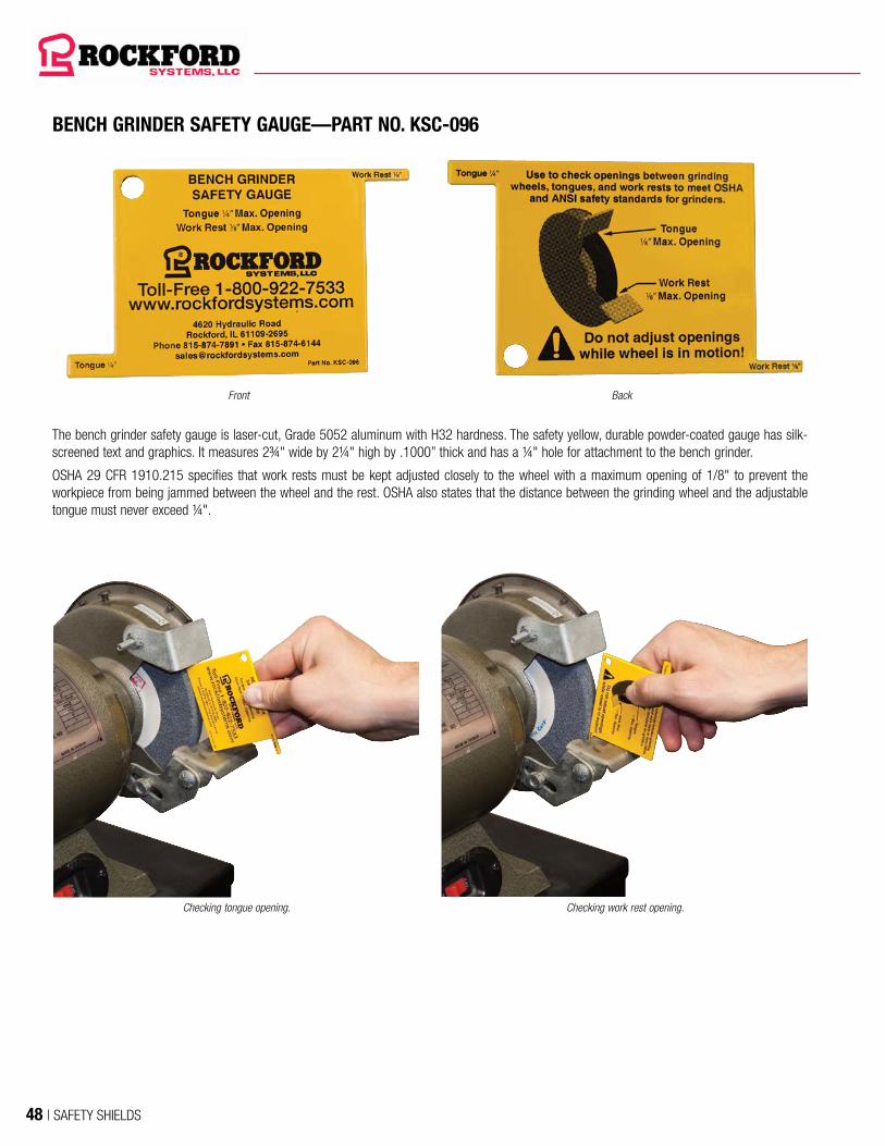
BENCH GRINDER SAFETY GAUGE—PART NO. KSC-096
The bench grinder safety gauge is laser-cut, Grade 5052 aluminum with H32 hardness. The safety yellow, durable powder-coated gauge has silk-screened text and graphics. It measures 2¾" wide by 2¼" high by .1000” thick and has a ¼" hole for attachment to the bench grinder.
OSHA 29 CFR 1910.215 specifies that work rests must be kept adjusted closely to the wheel with a maximum opening of 1/8" to prevent the workpiece from being jammed between the wheel and the rest. OSHA also states that the distance between the grinding wheel and the adjustable tongue must never exceed ¼".
Front
Checking tongue opening. Checking work rest opening.
Back
48 | SAFETY SHIELDS

These high-quality band saw shields place a barrier between an operator and flying debris generated at the point of operation. The transparent, L-shaped portion of the band saw shield is constructed of high-impact-resistant, 3/16"- thick clear polycarbonate.
Flexible spring-steel arms come in standard lengths of 12", 18", and 24" for attaching the shield.
The band saw shield assemblies are offered with a direct-mount base that is attached directly to the band saw. Mounting hardware is included.
BAND SAW SHIELD ASSEMBLIES
DIMENSIONS
Ordering InformationPART NO. DESCRIPTION
KYL-189 12" Direct-Mount Arm With 6" H x 6" W L-Shaped Shield (4" D)
KYL-190 18" Direct-Mount Arm With 6" H x 6" W L-Shaped Shield (4" D)
KYL-191 24" Direct-Mount Arm With 6" H x 6" W L-Shaped Shield (4" D)
KYL-175 6" x 6" L-Shaped Replacement Shield Only
6"
6"
4"
SAFETY ON BAND SAWS
SAFETY SHIELDS | 49

DISC AND BELT SANDER SHIELD ASSEMBLIES
Upper Belt ShieldPART NO. DESCRIPTION
KYL-226 Upper Belt Shield Assembly (L-Shaped Shield)
KYL-227 Upper Belt Shield Only (L-Shaped)
Lower Belt ShieldPART NO. DESCRIPTION
KYL-224 Lower Belt Shield Assembly (6" x 8" Shield)
KYL-225 Lower Belt Shield Only (6" x 8")
These high-quality, adjustable disc and belt sander shields place a barrier between an operator and flying debris generated at the point of operation. They fasten directly to the machine using 1" x 2" extruded aluminum with mounting hardware included. The transparent portion of the shield is constructed of high-impact-resistant, 3/16"-thick clear polycarbonate. Easy vertical adjustment of the shields is achieved simply by loosening and tightening the black knobs.
These shields can also be used on a combination belt sander & disc sander.
Disc sander shield assembly.
Upper Shield
Belt sander shield assembly.
Lower Shield
Disc Sander Shield
PART NO. DESCRIPTIONREPLACEMENT
SHIELD
KYL-228 9" Disc Sander Shield Assembly (6" x 13" Shield) KYL-229
KYL-230 12" Disc Sander Shield Assembly (7" x 16" Shield) KYL-231
KYL-232 16" Disc Sander Shield Assembly (9" x 20" Shield) KYL-233
KYL-234 20" Disc Sander Shield Assembly (11" x 24" Shield) KYL-235
KYL-236 24" Disc Sander Shield Assembly (13" x 28" Shield) KYL-237
6"
8"
3½"
14"
Upper Shield
14"
3½"
BELT SANDER SHIELD ASSEMBLIES
50 | SAFETY SHIELDS

ADJUSTABLE SLIDE SHIELDS
These high-quality adjustable slide shields can be used on drills, mills, saws, or special machine applications. The transparent portion of these shields is constructed of durable, clear 3/16"-thick polycarbonate. The shield places a barrier between an operator and the flying chips (swarf), sparks, and coolant generated at the point of operation.
These shields can be mounted vertically or horizontally on the flat surface of any machine. The transparent portion of the shield attaches to the mounting brackets and offers a slide adjustment of 3½". Two standard size shields with 30° sides are available: 7¾" x 11" and 9½" x 19". Contact Rockford Systems for other shield sizes or longer adjustments.
Adjustable slide shield on front column of machine.
5"
5"
51⁄8"
83⁄8"
7¾"
9½"
7" Front
103⁄8" Front
Adjustable Slide Shield—7" FrontPART NO. DESCRIPTION
KYL-192 Adjustable Slide Shield With 30° Angle and 7" Front
KYL-012 Replacement Shield—7" Front
Adjustable Slide Shield—103⁄8" FrontPART NO. DESCRIPTION
KYL-193 Adjustable Slide Shield With 30° Angle and 103⁄8" Front
KYL-017 Replacement Shield—103⁄8" Front
SAFETY ON DISC/BELT SANDERS & ALL-PURPOSE SHIELDS
SAFETY SHIELDS | 51
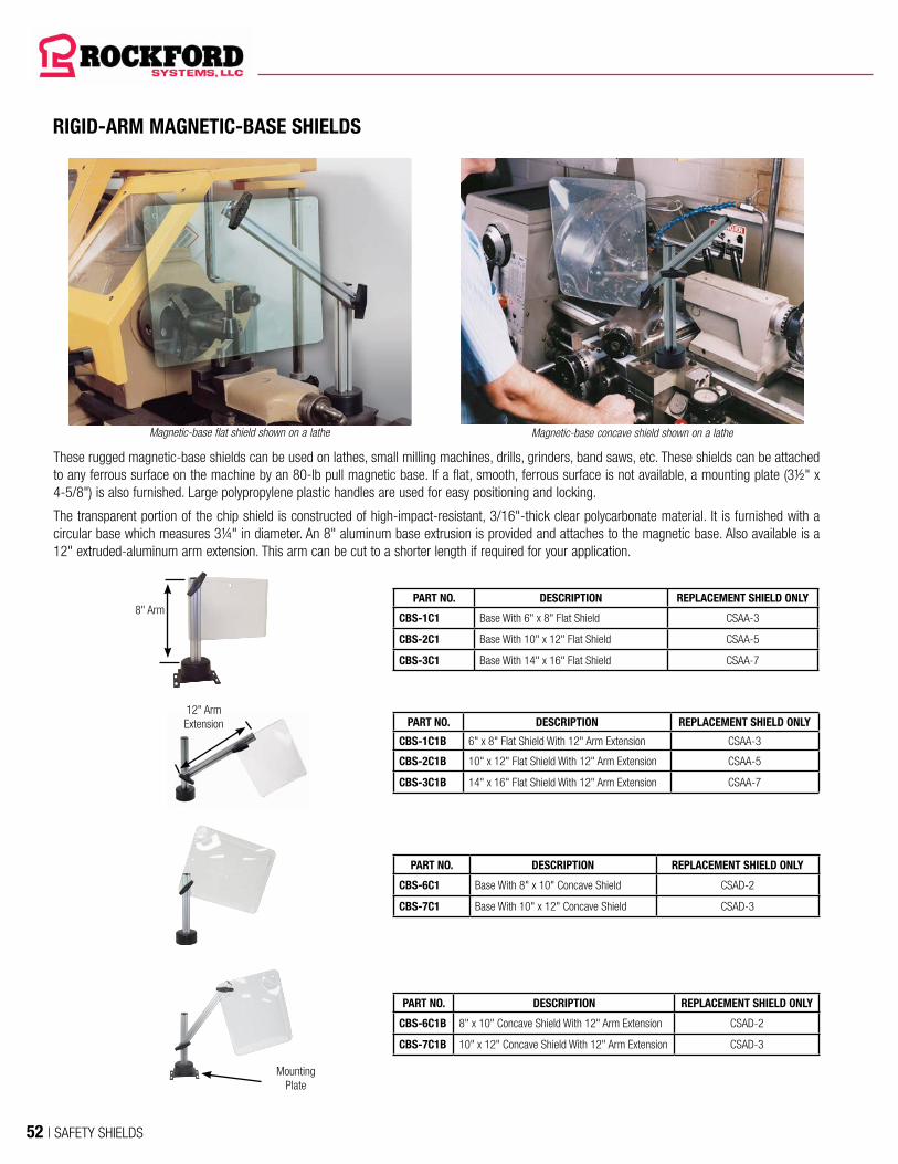
RIGID-ARM MAGNETIC-BASE SHIELDS
Magnetic-base flat shield shown on a lathe Magnetic-base concave shield shown on a lathe
8" ArmPART NO. DESCRIPTION REPLACEMENT SHIELD ONLY
CBS-1C1 Base With 6" x 8" Flat Shield CSAA-3
CBS-2C1 Base With 10" x 12" Flat Shield CSAA-5
CBS-3C1 Base With 14" x 16" Flat Shield CSAA-7
PART NO. DESCRIPTION REPLACEMENT SHIELD ONLY
CBS-1C1B 6" x 8" Flat Shield With 12" Arm Extension CSAA-3
CBS-2C1B 10" x 12" Flat Shield With 12" Arm Extension CSAA-5
CBS-3C1B 14" x 16" Flat Shield With 12" Arm Extension CSAA-7
PART NO. DESCRIPTION REPLACEMENT SHIELD ONLY
CBS-6C1 Base With 8" x 10" Concave Shield CSAD-2
CBS-7C1 Base With 10" x 12" Concave Shield CSAD-3
PART NO. DESCRIPTION REPLACEMENT SHIELD ONLY
CBS-6C1B 8" x 10" Concave Shield With 12" Arm Extension CSAD-2
CBS-7C1B 10" x 12" Concave Shield With 12" Arm Extension CSAD-3
These rugged magnetic-base shields can be used on lathes, small milling machines, drills, grinders, band saws, etc. These shields can be attached to any ferrous surface on the machine by an 80-lb pull magnetic base. If a flat, smooth, ferrous surface is not available, a mounting plate (3½" x 4-5/8") is also furnished. Large polypropylene plastic handles are used for easy positioning and locking.
The transparent portion of the chip shield is constructed of high-impact-resistant, 3/16"-thick clear polycarbonate material. It is furnished with a circular base which measures 3¼" in diameter. An 8" aluminum base extrusion is provided and attaches to the magnetic base. Also available is a 12" extruded-aluminum arm extension. This arm can be cut to a shorter length if required for your application.
12" Arm Extension
Mounting Plate
52 | SAFETY SHIELDS

UNIVERSAL BALL & SOCKET SHIELDS
A variety of these quality-constructed, very versatile shields are available. They are ideal for mills, drills, lathes, grinders, band saws, or similar equipment including woodworking machines. The shield places a barrier between operators or other employees in the area and the flying chips (swarf), sparks, and coolant generated from the tool. These shields are furnished with heavy universal steel ball-and-socket arms to provide simple movement and adjustment. Large polypropylene plastic handles are used for positioning and locking. Arms mount easily to the frame or column of the machine and include standard mounting hardware.
The shields offered are made of high-impact-resistant 3/16"-thick clear polycarbonate, selected for its toughness under impact to protect the operator. Each shield, except for the flat shield, has a hole in the left and right corners so the arm can be conveniently mounted on either side of the machine. Special size shields are available upon request.
Universal ball & socket shield on a milling machine.
Universal ball & socket shield shown on a drill press. Universal ball & socket shield shown on a band saw.
ALL-PURPOSE SHIELDS
SAFETY SHIELDS | 53

UNIVERSAL BALL & SOCKET SHIELDS (CONTINUED)
PART NO. DESCRIPTION
KYL-104 6" x 8" Flat Shield With 21" Universal Arm
KYL-105 6" x 8" Flat Shield With 31" Universal Arm
KYL-106 6" x 8" Flat Shield With 44" Universal Arm
CSAA-3 6" x 8" Flat Replacement Shield Only
CYF-016 Clamp Kit for Attaching to Table or Ledge
PART NO. DESCRIPTION
KYL-107 10" x 12" Flat Shield With 21" Universal Arm
KYL-108 10" x 12" Flat Shield With 31" Universal Arm
KYL-109 10" x 12" Flat Shield With 44" Universal Arm
CSAA-5 10" x 12" Flat Replacement Shield Only
CYF-016 Clamp Kit for Attaching to Table or Ledge
PART NO. DESCRIPTION
KYL-110 30° Angle Shield 8" H (7" Front) With 21" Universal Arm
KYL-111 30° Angle Shield 8" H (7" Front) With 31" Universal Arm
KYL-112 30° Angle Shield 8" H (7" Front) With 44" Universal Arm
KYL-012 30° Angle 8" H (7" Front) Replacement Shield Only
CYF-016 Clamp Kit for Attaching to Table or Ledge
PART NO. DESCRIPTION
KYL-113 30° Angle Shield 9½" H (103⁄8" Front) With 21" Universal Arm
KYL-114 30° Angle Shield 9½" H (103⁄8" Front) With 31" Universal Arm
KYL-115 30° Angle Shield 9½" H (103⁄8" Front) With 44" Universal Arm
KYL-017 30° Angle 9½" H (103⁄8" Front) Replacement Shield Only
CYF-016 Clamp Kit for Attaching to Table or Ledge
All Steel Pivot Balls Are Hardened For Longevity
54 | SAFETY SHIELDS

UNIVERSAL BALL & SOCKET SHIELDS (CONTINUED)
PART NO. DESCRIPTION
KYL-127 30° & 90° Angle Shield 9½" H (103⁄8" Front) With 21" Universal Arm
KYL-128 30° & 90° Angle Shield 9½" H (103⁄8" Front) With 31" Universal Arm
KYL-129 30° & 90° Angle Shield 9½" H (103⁄8" Front) With 44" Universal Arm
KYL-126 30° & 90° Angle 9½" H (103⁄8" Front) Replacement Shield Only
CYF-016 Clamp Kit for Attaching to Table or Ledge
PART NO. DESCRIPTION
KYL-116 90° Angle Shield 9½" H (11" Front) With 21" Universal Arm
KYL-117 90° Angle Shield 9½" H (11" Front) With 31" Universal Arm
KYL-118 90° Angle Shield 9½" H (11" Front) With 44" Universal Arm
KYL-018 90° Angle 9½" H (11" Front) Replacement Shield Only
CYF-016 Clamp Kit for Attaching to Table or Ledge
PART NO. DESCRIPTION
KYL-119 8" x 10" Concave Shield With 21" Universal Arm
KYL-120 8" x 10" Concave Shield With 31" Universal Arm
KYL-121 8" x 10" Concave Shield With 44" Universal Arm
CSAD-2 8" x 10" Concave Replacement Shield Only
CYF-016 Clamp Kit for Attaching to Table or Ledge
PART NO. DESCRIPTION
KYL-122 10" x 12" Concave Shield With 21" Universal Arm
KYL-123 10" x 12" Concave Shield With 31" Universal Arm
KYL-124 10" x 12" Concave Shield With 44" Universal Arm
CSAD-3 10" x 12" Concave Replacement Shield Only
CYF-016 Clamp Kit for Attaching to Table or Ledge
CYF-016—Clamp kit attaches to table or ledge.
THE 90º SIDE PREVENTS INTERFERENCE WITH A DRILL PRESS HANDLE
ALL-PURPOSE SHIELDS
SAFETY SHIELDS | 55

FLEXIBLE SPRING-STEEL ARM SHIELDS
Flexible spring-steel arm shield on milling machine.
Flexible spring-steel arm shield on milling machine.
Flexible spring-steel arm shield on lathe.
These flexible arms are made of high-quality, heavy-duty ¾"-diameter spring steel covered with vinyl to protect from grease, oil, and contaminants that could weaken their holding power. They offer virtually unlimited adjustment possibilities and long-term holding power.
The shield can be used on lathes, drill presses, milling machines, grinders, band saws, woodworking machines, and similar equipment. It places a barrier between an operator and flying chips (swarf), sparks, and splashing coolant generated at the point of operation. The transparent portion of these flexible-arm shields is constructed of high-impact-resistant, 3/16"-thick polycarbonate. Special shield sizes are available up to 12" x 12"; please call our sales department at 1-800-922-7533 for more information.
The flexible-arm shields have two mounting options: direct or magnetic. The direct-mount base can be fastened directly to a machine with two ¼" fasteners (included). The magnetic base consists of a 3"-diameter magnet with 100-lb holding force. If an adequate flat, smooth, ferrous mounting surface is not available, an optional steel mounting plate can be permanently attached to the machine to hold the magnetic base.
56 | SAFETY SHIELDS

FLEXIBLE SPRING-STEEL ARM SHIELDS (CONTINUED)
PART NO. DESCRIPTION
KYL-096 6" x 8" Flat Shield and 12" Arm With Direct-Mount Base
KYL-097 6" x 8" Flat Shield and 18" Arm With Direct-Mount Base
KYL-132 6" x 8" Flat Shield and 24" Arm With Direct-Mount Base
CSAA-3 6" x 8" Flat Replacement Shield Only
PART NO. DESCRIPTION
KYL-100 6" x 8" Flat Shield and 12" Arm With Magnetic Base
KYL-101 6" x 8" Flat Shield and 18" Arm With Magnetic Base
KYL-133 6" x 8" Flat Shield and 24" Arm With Magnetic Base
CSAA-3 6" x 8" Flat Replacement Shield Only
FKT-1106 Optional 3½" x 45⁄8" Steel Mounting Plate (Fasteners Not Included)
PART NO. DESCRIPTION
KYL-098 10" x 12" Flat Shield and 12" Arm With Direct-Mount Base
KYL-099 10" x 12" Flat Shield and 18" Arm With Direct-Mount Base
KYL-134 10" x 12" Flat Shield and 24" Arm With Direct-Mount Base
CSAA-5 10" x 12" Flat Replacement Shield Only
PART NO. DESCRIPTION
KYL-102 10" x 12" Flat Shield and 12" Arm With Magnetic Base
KYL-103 10" x 12" Flat Shield and 18" Arm With Magnetic Base
KYL-135 10" x 12" Flat Shield and 24" Arm With Magnetic Base
CSAA-5 10" x 12" Flat Replacement Shield Only
FKT-1106 Optional 3½" x 45⁄z" Steel Mounting Plate (Fasteners Not Included)
Optional Mounting Plate
MADE OF ¾"-DIAMETER VINYL-COVERED SPRING STEEL
ALL-PURPOSE SHIELDS
SAFETY SHIELDS | 57
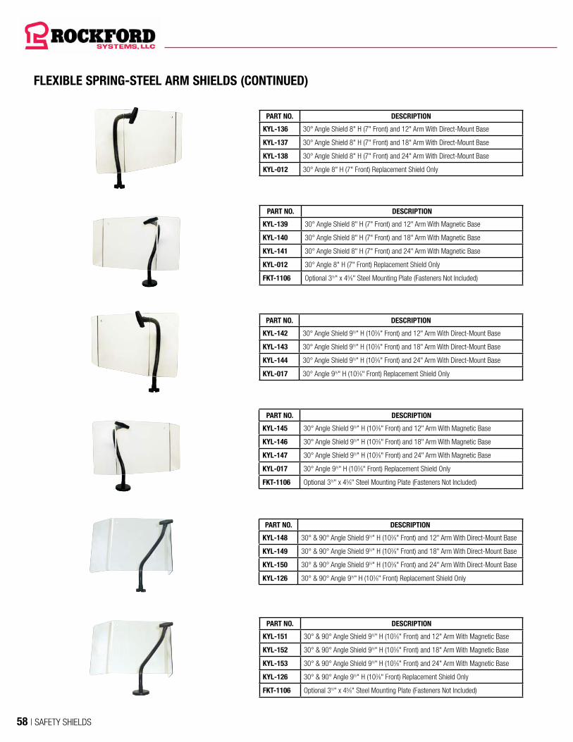
FLEXIBLE SPRING-STEEL ARM SHIELDS (CONTINUED)
PART NO. DESCRIPTION
KYL-136 30° Angle Shield 8" H (7" Front) and 12" Arm With Direct-Mount Base
KYL-137 30° Angle Shield 8" H (7" Front) and 18" Arm With Direct-Mount Base
KYL-138 30° Angle Shield 8" H (7" Front) and 24" Arm With Direct-Mount Base
KYL-012 30° Angle 8" H (7" Front) Replacement Shield Only
PART NO. DESCRIPTION
KYL-142 30° Angle Shield 9½" H (103⁄8" Front) and 12" Arm With Direct-Mount Base
KYL-143 30° Angle Shield 9½" H (103⁄8" Front) and 18" Arm With Direct-Mount Base
KYL-144 30° Angle Shield 9½" H (103⁄8" Front) and 24" Arm With Direct-Mount Base
KYL-017 30° Angle 9½" H (103⁄8" Front) Replacement Shield Only
PART NO. DESCRIPTION
KYL-148 30° & 90° Angle Shield 9½" H (103⁄8" Front) and 12" Arm With Direct-Mount Base
KYL-149 30° & 90° Angle Shield 9½" H (103⁄8" Front) and 18" Arm With Direct-Mount Base
KYL-150 30° & 90° Angle Shield 9½" H (103⁄8" Front) and 24" Arm With Direct-Mount Base
KYL-126 30° & 90° Angle 9½" H (103⁄8" Front) Replacement Shield Only
PART NO. DESCRIPTION
KYL-145 30° Angle Shield 9½" H (103⁄8" Front) and 12" Arm With Magnetic Base
KYL-146 30° Angle Shield 9½" H (103⁄8" Front) and 18" Arm With Magnetic Base
KYL-147 30° Angle Shield 9½" H (103⁄8" Front) and 24" Arm With Magnetic Base
KYL-017 30° Angle 9½" H (103⁄8" Front) Replacement Shield Only
FKT-1106 Optional 3½" x 45⁄8" Steel Mounting Plate (Fasteners Not Included)
PART NO. DESCRIPTION
KYL-151 30° & 90° Angle Shield 9½" H (103⁄8" Front) and 12" Arm With Magnetic Base
KYL-152 30° & 90° Angle Shield 9½" H (103⁄8" Front) and 18" Arm With Magnetic Base
KYL-153 30° & 90° Angle Shield 9½" H (103⁄8" Front) and 24" Arm With Magnetic Base
KYL-126 30° & 90° Angle 9½" H (103⁄8" Front) Replacement Shield Only
FKT-1106 Optional 3½" x 45⁄8" Steel Mounting Plate (Fasteners Not Included)
PART NO. DESCRIPTION
KYL-139 30° Angle Shield 8" H (7" Front) and 12" Arm With Magnetic Base
KYL-140 30° Angle Shield 8" H (7" Front) and 18" Arm With Magnetic Base
KYL-141 30° Angle Shield 8" H (7" Front) and 24" Arm With Magnetic Base
KYL-012 30° Angle 8" H (7" Front) Replacement Shield Only
FKT-1106 Optional 3½" x 45⁄8" Steel Mounting Plate (Fasteners Not Included)
58 | SAFETY SHIELDS

FLEXIBLE SPRING-STEEL ARM SHIELDS (CONTINUED)
PART NO. DESCRIPTION
KYL-154 90° Angle Shield 9½" H (11" Front) and 12" Arm With Direct-Mount Base
KYL-155 90° Angle Shield 9½" H (11" Front) and 18" Arm With Direct-Mount Base
KYL-156 90° Angle Shield 9½" H (11" Front) and 24" Arm With Direct-Mount Base
KYL-018 90° Angle 9½" H (11" Front) Replacement Shield Only
PART NO. DESCRIPTION
KYL-157 90° Angle Shield 9½" H (11" Front) and 12" Arm With Magnetic Base
KYL-158 90° Angle Shield 9½" H (11" Front) and 18" Arm With Magnetic Base
KYL-159 90° Angle Shield 9½" H (11" Front) and 24" Arm With Magnetic Base
KYL-018 90° Angle 9½" H (11" Front) Replacement Shield Only
KYL-1106 Optional 3½" x 45⁄8" Steel Mounting Plate (Fasteners Not Included)
PART NO. DESCRIPTION
KYL-160 8" x 10" Concave Shield and 12" Arm With Direct-Mount Base
KYL-161 8" x 10" Concave Shield and 18" Arm With Direct-Mount Base
KYL-162 8" x 10" Concave Shield and 24" Arm With Direct-Mount Base
CSAD-2 8" x 10" Concave Replacement Shield Only
PART NO. DESCRIPTION
KYL-166 10" x 12" Concave Shield and 12" Arm With Direct-Mount Base
KYL-167 10" x 12" Concave Shield and 18" Arm With Direct-Mount Base
KYL-168 10" x 12" Concave Shield and 24" Arm With Direct-Mount Base
CSAD-3 10" x 12" Concave Replacement Shield Only
PART NO. DESCRIPTION
KYL-163 8" x 10" Concave Shield and 12" Arm With Magnetic Base
KYL-164 8" x 10" Concave Shield and 18" Arm With Magnetic Base
KYL-165 8" x 10" Concave Shield and 24" Arm With Magnetic Base
CSAD-2 8" x 10" Concave Replacement Shield Only
FKT-1106 Optional 3½" x 45⁄8" Steel Mounting Plate (Fasteners Not Included)
PART NO. DESCRIPTION
KYL-169 10" x 12" Concave Shield and 12" Arm With Magnetic Base
KYL-170 10" x 12" Concave Shield and 18" Arm With Magnetic Base
KYL-171 10" x 12" Concave Shield and 24" Arm With Magnetic Base
CSAD-3 10" x 12" Concave Replacement Shield Only
FKT-1106 Optional 3½" x 45⁄8" Steel Mounting Plate (Fasteners Not Included)
ALL-PURPOSE SHIELDS
SAFETY SHIELDS | 59
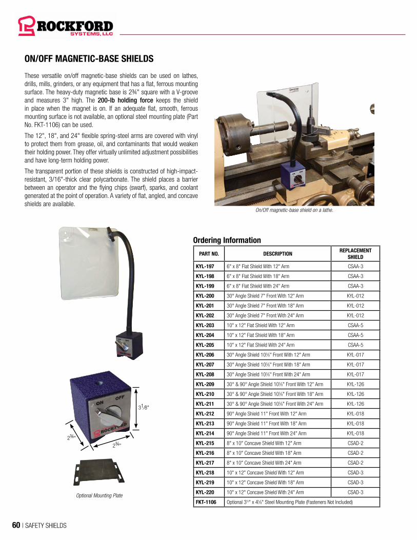
ON/OFF MAGNETIC-BASE SHIELDS
Ordering Information
PART NO. DESCRIPTIONREPLACEMENT
SHIELD
KYL-197 6" x 8" Flat Shield With 12" Arm CSAA-3
KYL-198 6" x 8" Flat Shield With 18" Arm CSAA-3
KYL-199 6" x 8" Flat Shield With 24" Arm CSAA-3
KYL-200 30° Angle Shield 7" Front With 12" Arm KYL-012
KYL-201 30° Angle Shield 7" Front With 18" Arm KYL-012
KYL-202 30° Angle Shield 7" Front With 24" Arm KYL-012
KYL-203 10" x 12" Flat Shield With 12" Arm CSAA-5
KYL-204 10" x 12" Flat Shield With 18" Arm CSAA-5
KYL-205 10" x 12" Flat Shield With 24" Arm CSAA-5
KYL-206 30° Angle Shield 103⁄8" Front With 12" Arm KYL-017
KYL-207 30° Angle Shield 103⁄8" Front With 18" Arm KYL-017
KYL-208 30° Angle Shield 103⁄8" Front With 24" Arm KYL-017
KYL-209 30° & 90° Angle Shield 103⁄8" Front With 12" Arm KYL-126
KYL-210 30° & 90° Angle Shield 103⁄8" Front With 18" Arm KYL-126
KYL-211 30° & 90° Angle Shield 103⁄8" Front With 24" Arm KYL-126
KYL-212 90° Angle Shield 11" Front With 12" Arm KYL-018
KYL-213 90° Angle Shield 11" Front With 18" Arm KYL-018
KYL-214 90° Angle Shield 11" Front With 24" Arm KYL-018
KYL-215 8" x 10" Concave Shield With 12" Arm CSAD-2
KYL-216 8" x 10" Concave Shield With 18" Arm CSAD-2
KYL-217 8" x 10" Concave Shield With 24" Arm CSAD-2
KYL-218 10" x 12" Concave Shield With 12" Arm CSAD-3
KYL-219 10" x 12" Concave Shield With 18" Arm CSAD-3
KYL-220 10" x 12" Concave Shield With 24" Arm CSAD-3
FKT-1106 Optional 3½" x 45⁄8" Steel Mounting Plate (Fasteners Not Included)
These versatile on/off magnetic-base shields can be used on lathes, drills, mills, grinders, or any equipment that has a flat, ferrous mounting surface. The heavy-duty magnetic base is 2¾" square with a V-groove and measures 3" high. The 200-lb holding force keeps the shield in place when the magnet is on. If an adequate flat, smooth, ferrous mounting surface is not available, an optional steel mounting plate (Part No. FKT-1106) can be used.
The 12", 18", and 24" flexible spring-steel arms are covered with vinyl to protect them from grease, oil, and contaminants that would weaken their holding power. They offer virtually unlimited adjustment possibilities and have long-term holding power.
The transparent portion of these shields is constructed of high-impact-resistant, 3/16"-thick clear polycarbonate. The shield places a barrier between an operator and the flying chips (swarf), sparks, and coolant generated at the point of operation. A variety of flat, angled, and concave shields are available.
On/Off magnetic-base shield on a lathe.
Optional Mounting Plate
2¾"2¾"
31⁄8"
60 | SAFETY SHIELDS

These shields can be used to protect the area between machines, the backside of machines, along aisles, etc.
These free-standing adjustable shield assemblies are available in a wide range of sizes. They are constructed of 3/16"-thick polycarbonate material surrounded by aluminum framing. The shield can easily be adjusted up or down on the stands. The stands are constructed of 2"-square extruded aluminum. Each base includes four holes for permanent mounting to the floor. Four standard sizes are available. Special size shield assemblies are available upon request.
FREE-STANDING SHIELD ASSEMBLY
Ordering InformationPART NO. DESCRIPTION
KYL-026 48" H x 48" L Shield Size
KYL-027 48" H x 60" L Shield Size
KYL-028 48" H x 72" L Shield Size
KYL-029 48" H x 96" L Shield Size
Free-standing shield used to protect the area around a milling machine from flying chips.
Clear Polycarbonate
Stands
ALL-PURPOSE SHIELDS
SAFETY SHIELDS | 61

LOCKOUTS
ELECTRICAL PLUG LOCKOUT
PART NO. KYM-088This lockout container can lockout plugs up to 3" wide and 5½" long with a maximum cord diameter of 1¼".
The lockout consists of a round container and two cover plates made of
a durable and chemically resistant thermoplastic. The cover plates, when used singularly or combined, are locked to produce a universally fitting electrical plug lockout device.
This lockout is bright yellow so it can also serve as a visual warning to other plant personnel.
These lockout devices accommodate a large variety of electrical plugs. The large device (KYM-987) also locks out necked-down pneumatic male fittings commonly attached to compressed air hoses. These devices accommodate up to four padlocks with 9/32" maximum shackle diameter.
PART NO. KYM-984 For plugs up to 1½" wide, 1½" high, and 3" long with a maximum cord diameter of ½"
PART NO. KYM-987 For plugs up to 3½" wide, 3½" high, and 6" long with a maximum cord diameter of ¾"
KYM-987KYM-984
PLUGOUT
PART NO. KYM-983This lockout container accepts lockout plugs up to 2¾" wide and 4¾" long with a maximum cord diameter of 2¾". It is constructed of high-impact, yellow UV-stabilized polymer. I t has an easy to use two-step close and slide assembly. It allows the use of four individual padlocks (up to 3/8" shackle diameter). A lockout hasp can be used if more locks are required. An advantage to this plug lockout is that it can be stored on the cord when not in use. This device is 4¼" wide and 7¼" long.
PLUG HUGGER—PART NO. KYM-199This device is ideal for frequently locked-out cords. It slides over the plug’s blades and locks with a key. It can only be used on standard 125-V, 15-A plugs (polarized or nonpolarized) with a hole on both blades.
ELECTRICAL POWER CUTOFF SYSTEM (INTERLOCK)This interlock assembly can be interfaced into the control system so when the plug is pulled, the machine or equipment becomes inoperable. It includes a two-prong plug, a 24" chain, a receptacle, and an electrical mounting box.
PART NO. KTS-518One-Contact Interlock System With 24" Chain
PART NO. KTS-533 Two-Contact Interlock System With 24" Chain
LOCKOUT HASPSThese lockout hasps are made from 12-gauge steel that is epoxy-coated for superior rust resistance and added dielectric strength. The yellow plastic coating on the lock area is for visibility. These devices accept up to six padlocks with 9/32" maximum shackle diameter.
PART NO. KYM-988 1" Diameter Lockout Hasp
PART NO. KYM-989 1½" Diameter Lockout HaspKYM-988
PART NO. KYM-192
PART NO. KYM-193
PART NO. KYM-194
PART NO. KYM-195
PART NO. KYM-196
REVERSE SIDE
TAGOUTSThese tagouts are 2-7/8" x 5½" x .055" thick, and made of a polyethylene material. They meet the requirements of OSHA 29 CFR 1910.147 for lockout/tagout. The reverse side of each tagout is the same.
LOCK-A-PLUGS
KYM-989
62 | SAFETY SHIELDS

SLIDE-OPERATED VALVEThis three-way valve is operated with the manual movement of a slide that opens and closes the valve. This valve shuts off air at the machine and then bleeds off downstream air. It can be locked only in the off position.
LOCKOUT VALVES
SINGLE-PHASE DISCONNECT SWITCH WITH MAGNETIC MOTOR STARTER AND SELF-LATCHING EMERGENCY-STOP BUTTON This single-phase unit is designed for motors that have built-in overloads. Typical applications for these combinations include smaller crimping machines, grinders, drill presses, and all types of saws.
PART NO. CSS-055 (115 V, ½ HP MAX.)The 115-V, 15-A disconnect switch and nonreversing magnetic motor starter are housed in a NEMA 12 enclosure. Enclosure size is 8" x 6" x 3½". It includes a self-latching red emergency-stop palm button and a green motor control on push button. It can be used on machines with 115-V power and is rated up to ½ HP maximum.
The disconnect switch has a rotary operating handle which is lockable in the off position only. This meets OSHA regulations and ANSI standards.
For machines with 230-V AC single-phase motors, a transformer is required to reduce the control circuit voltage to 115-V AC in order to comply with NFPA 79. See the RSD series disconnect switches, motor starters, and combinations on pages 64-65.
EEZ-ON VALVEThis valve shuts off air supply to the machine and bleeds downstream air when the valve is closed. When the valve is open, it gradually allows air into the air system to prevent damage to air components. It can be locked only in the off position. This valve is furnished with a muffler.
PART NO.PORT SIZE
IN-OUT
RCD-113 ½"RCD-114 ¾"
PART NO.PORT SIZE
IN-OUT EXHAUST
RCD-121 ½" ¾"RCD-122 ¾" ¾"
SINGLE-PHASE STARTER WITH SELF-LATCHING EMERGENCY-STOP BUTTONPART NO. CSF-082 (115 V, ½ HP MAX.)The 115-V, 15-A nonreversing magnetic motor starter, self-latching red emergency-stop palm button, and green motor control on push button are housed in a NEMA 4 polycarbonate enclosure. Enclosure size is 5" x 5" x 4". It can be used for machines with 115-V power and is rated up to ½ HP maximum.
For machines with 230-V AC single-phase motors, a transformer is required to reduce the control circuit voltage to 115-V AC in order to comply with NFPA 79. See the RSD series disconnect switches, motor starters, and combinations on pages 63-64.
PART NO. CSF-301 (115 V, 2 HP MAX.)The 115-V, 30-A nonreversing magnetic motor starter, self-latching red emergency-stop palm button, and green motor control on push button are housed in a NEMA 12 enclosure. Enclosure size is 8" x 6" x 6". It can be used for machines with 115-V power and is rated up to 2 HP maximum.
For machines with 230-V AC single-phase motors, a transformer is required to reduce the control circuit voltage to 115-V AC in order to comply with NFPA 79. See the RSD series disconnect switches, motor starters, and combinations on pages 63-64.
DISCONNECT SWITCHES, MOTOR STARTERS, AND ACCESSORIES
SAFETY SHIELDS | 63
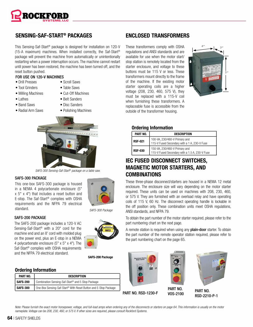
SENSING-SAF-START® PACKAGES
SAFS-300 Sensing-Saf-Start® package on a table saw.
This Sensing-Saf-Start® package is designed for installation on 120-V (15-A maximum) machines. When installed correctly, the Saf-Start® package will prevent the machine from automatically or unintentionally restarting when a power interruption occurs. The machine cannot restart until power has been restored, the machine has been turned off, and the reset button pushed.FOR USE ON 120-V MACHINES• Drill Presses • Scroll Saws• Tool Grinders • Table Saws• Milling Machines • Cut-Off Machines• Lathes • Belt Sanders• Band Saws • Disc Sanders• Radial Arm Saws • Polishing Machines
SAFS-200 PACKAGEThe SAFS-200 package includes a 120-V AC Sensing-Saf-Start® with a 20" cord for the machine end and an 8' cord with molded plug on the power end, plus an E-stop in a NEMA 4 polycarbonate enclosure (5" x 5" x 4"). The Saf-Start® complies with OSHA requirements and the NFPA 79 electrical standard.
SAFS-200 Package
SAFS-300 Package
SAFS-300 PACKAGEThis one-box SAFS-300 package is housed in a NEMA 4 polycarbonate enclosure (5" x 5" x 4") that includes a reset button and E-stop. The Saf-Start® complies with OSHA requirements and the NFPA 79 electrical standard.
Ordering InformationPART NO. DESCRIPTION
SAFS-200 Combination Sensing-Saf-Start® and E-Stop Package
SAFS-300 One-Box Sensing-Saf-Start® With Reset Button and E-Stop Package
These transformers comply with OSHA regulations and ANSI standards and are available for use when the motor start/stop station is remotely located from the starter enclosure, and voltage to these buttons must be 115 V or less. These transformers mount directly to the frame of the machine. If the existing motor starter operating coils are a higher voltage (208, 230, 460, 575 V), they must be replaced with a 115-V coil when furnishing these transformers. A replaceable fuse is accessible from the outside of the transformer housing.
ENCLOSED TRANSFORMERS
IEC FUSED DISCONNECT SWITCHES, MAGNETIC MOTOR STARTERS, AND COMBINATIONS
Ordering InformationPART NO. DESCRIPTION
RSF-021100-VA, 230/460-V Primary and 115-V Fused Secondary with a 1 A, 230-V Fuse
RSF-030150-VA, 230/460-V Primary and 115-V Fused Secondary with a 1.5 A, 230-V Fuse
4½" 3½"
5½"
These three-phase disconnect/starters are housed in a NEMA 12 metal enclosure. The enclosure size will vary depending on the motor starter required. These units can be used on machines with 208, 230, 460, or 575 V. They are furnished with an overload relay and have operating coils of 115 V, 60 Hz. The disconnect operating handle is lockable in the off position only. These combination units meet OSHA regulations, ANSI standards, and NFPA 79.
To obtain the part number of the motor starter required, please refer to the part numbering chart on the next page.
A remote station is required when using any plain-door starter. To obtain the part number of the remote operator station required, please refer to the part numbering chart on the page 65.
PART NO. RSD-1230-FPART NO. VOS-2100
PART NO. RSD-2210-P-1
Note: Please furnish the exact motor horsepower, voltage, and full-load amps when ordering any of the disconnects or starters on page 64. This information is usually on the motor nameplate. Voltage can be 208, 230, 460, or 575 V. If other sizes are required, please consult Rockford Systems.
64 | SAFETY SHIELDS

SELECTING A DISCONNECT, STARTER, OR COMBINATION DISCONNECT/STARTER(S)
To determine the 9-digit configured part number for a disconnect, starter, or combination disconnect/starter(s) required, follow directions 1-7 below and use the information in the PART NUMBERING SYSTEM CHART below.
The first 3 digits for all disconnects, starters, or combination disconnect/starter(s) are RSD.
The 4th digit determines the size of the disconnect switch, if required. Zero (0) indicates no disconnect switch provided.
The 5th digit determines the type of the main motor starter and/or 2nd motor starter. Zero (0) indicates no starters.
The 6th digit determines the size of the main motor starter. Zero (0) indicates no main motor starter.
The 7th digit determines the size of the 2nd motor starter. Zero (0) indicates no 2nd motor starter.
The 8th digit (if required) determines the configuration and location of the operator controls.
The 9th digit determines if a transformer and/or wiring is required.
DISCONNECT AND STARTER(S)RSD —Separate or Combination
DISCONNECT SWITCH SIZE (IEC) (PLUS MAXIMUM MAIN MOTOR FLA)
0 —No Disconnect Switch1 —30-A CC Disconnect—1- to 17-FLA Total Motor Current2 —30-A J Disconnect—1- to 20-FLA Total Motor Current3 —60-A J Disconnect—21- to 40-FLA Total Motor Current4 —100-A J Disconnect—41- to 66-FLA Total Motor Current5 —200-A J Disconnect—67- to 133-FLA Total Motor Current6 —400-A J Disconnect—134- to 266-FLA Total Motor Current
CONFIGURATION & OPERATOR LOCATION- —Blank—No Specific ConfigurationP —All Operators Remote (Plain Door)F —All Motor Operators on Door of EnclosureX —F Configuration With E-Stop in Place of Single-Motor StopY —F Configuration With Addition of E-Stop
REVERSING/NONREVERSING MOTOR STARTER0 —No Starters1 —Nonreversing Main Motor Starter2 —Reversing Main Motor Starter3 —Nonreversing Main Motor Starter & Nonreversing 2nd Motor4 —Nonreversing Main Motor Starter & Reversing 2nd Motor5 —Reversing Main Motor Starter & Nonreversing 2nd Motor6 —Reversing Main Motor Starter & Reversing 2nd Motor7 —Nonreversing 2-Speed Main Motor Starter8 —Reversing 2-Speed Main Motor Starter9 —Nonreversing 2-Speed Main Motor Starer & Nonrev. 2nd MotorA —Nonreversing 2-Speed Main Motor Starter & Reversing 2nd MotorB —Reversing 2-Speed Main Motor Starter & Nonreversing 2nd MotorC —Reversing 2-Speed Main Motor Starter & Reversing 2nd Motor
MAIN MOTOR STARTER SIZE0 —No Main Motor Starter
Motor Horsepower Chart1-Phase 3-Phase
IEC 115 V 230 V 208 V 230 V 460 V 575 V1 —12 A 1/2 1 2 3 7.5 7.52 —18 A 3/4 2 5 5 10 103 —25 A 2 3 5 7.5 15 154 —32 A 2 5 7.5 10 20 205 —40 A 3 7.5 10 10 30 306 —50 A 3 10 15 15 30 407 —65 A 5 10 20 20 50 508 —80 A 7.5 15 25 30 60 759 —95 A 7.5 20 30 30 60 75A —115 A 10 25 30 40 75 100B —185 A 15 30 50 60 125 150C —265 A – – 75 100 200 200
2nd MOTOR STARTER SIZE0 —No Main Motor Starter
Motor Horsepower Chart1-Phase 3-Phase
IEC 115 V 230 V 208 V 230 V 460 V 575 V1 —12 A 1/2 1 2 3 7.5 7.52 —18 A 3/4 2 3 5 10 103 —25 A 2 3 5 7.5 15 154 —32 A 2 5 7.5 10 20 205 —40 A 3 7.5 10 10 30 306 —50 A 3 10 15 15 30 407 —65 A 5 10 20 20 50 508 —80 A 7.5 15 25 30 60 759 —95 A 7.5 20 30 30 60 75A —115 A 10 25 30 40 75 100B —185 A 15 30 50 60 125 150C —265 A – – 75 100 200 200
DISCONNECT AND STARTER(S) PART NUMBERING SYSTEM CHART
R S D - X X X X - X - X
Please see page 65 for an example of a disconnect and starter(s) part number.
MODIFIER- —Blank—No Specific Configuration, Terminals, Transformer,
or Wiring1 —Generically Numbered and Wired to Terminals
—Includes Transformer2 —Generically Numbered and Wired to Terminals
—Without Transformer
DISCONNECT SWITCHES, MOTOR STARTERS, AND ACCESSORIES
SAFETY SHIELDS | 65

REMOTE OPERATOR STATION ORIENTATIONHOS —Horizontal Operator StationVOS —Vertical Operator Station
MAIN MOTOR START/STOP/E-STOP OPERATORS1 —Start/Stop Push Buttons2 —Start/E-Stop Push Buttons3 —Start/Stop/E-Stop Buttons4 —E-Stop Button Only
MAIN MOTOR SPEED CHANGE0 —No Speed Change1 —Fast/Slow Selector Switch2 —Fast/Slow Push Buttons
MAIN MOTOR JOG0 —No Jog1 —Jog/Run Selector Switch
2nd MOTOR OPERATORS- —Blank—No 2nd Motor1 —Start/Stop Push Buttons2 — Start/Stop Push Buttons &
Forward/Reverse Selector Switch
MAIN MOTOR FORWARD/REVERSE OPERATORS0 —No Forward/Reverse Operators1 —Forward/Reverse Selector Switch*2 —Forward/Reverse Push Buttons
REMOTE OPERATOR STATION PART NUMBERING SYSTEM CHART
X X X - X X X X - X
SELECTING A REMOTE OPERATOR STATION
To determine the 8-digit configured part number for a remote operator station required, follow directions 1-3 below and use the information in the PART NUMBERING SYSTEM CHART below.
The first 3 digits determine the orientation of the remote operator station.
Digits 4 through 7 determine motor operators. Zero (0) indicates no operator(s).
The 8th digit (if required) determines the 2nd motor operators.
DISCONNECT AND STARTERS PART NUMBER EXAMPLE REMOTE OPERATOR PART NUMBER EXAMPLE
The example shown above, RSD-3521-P-1, indicates that the enclosure containing the combination disconnect/starter(s) has a 60-A disconnect switch, a 17-A reversing main motor starter, and a 12-A nonreversing 2nd motor starter. All motor controls will be in a remote station. This disconnect/starter(s) will be generically numbered and wired to terminals and will include a transformer.
1 2 3 4 5 6 7 R S D - 3 5 2 1 - P - 1
1 2 3 V O S - 3 1 0 0 - 1
The example shown above, VOS-3100-1, indicates that it is a vertical-oriented remote operator station which includes main motor start/stop/E-stop buttons, main motor forward/reverse selector switch, and start/stop push buttons for the 2nd motor starter.
* Must be configured with a start push button
66 | SAFETY SHIELDS

REMOTE OPERATOR STATIONS
PART NO. HOS-4000This 4½" x 3½" x 3" station has a self-latching red emergency-stop palm button in a NEMA 12 metal enclosure. To reset this button, turn it to the right.
PART NO. VOS-2000
(FOR USE WITH NONREVERSING MOTOR STARTERS)This 6¾" x 3½" x 3" station has a motor on push button and a self-latching red emergency-stop palm button in a NEMA 12 metal enclosure.
PART NO. HOS-4201
(FOR USE WITH REVERSING MOTOR STARTERS)This 3½" x 10½" x 3" station has a motor jog/run selector switch, forward and reverse push buttons, and a self-latching emergency-stop palm button in a NEMA 12 metal enclosure.
PART NO. VOS-1000
(FOR USE WITH NONREVERSING MOTOR STARTERS)This 6¾" x 3½" x 3" station has motor on and stop push buttons in a NEMA 12 metal enclosure.
PART NO. HOS-4000
PART NO. VOS-2000
PART NO. HOS-4201
PART NO. VOS-1000
PART NO. VOS-2100
PART NO. VOS-1100
PART NO. HOS-4200
PART NO. HOS-4200
(FOR USE WITH REVERSING MOTOR STARTERS)This 3½" x 8¾" x 3" station has motor forward and reverse push buttons and a self-latching emergency-stop palm button in a NEMA 12 metal enclosure.
PART NO. VOS-1100
(FOR USE WITH REVERSING MOTOR STARTERS)This 8¾" x 3½" x 3" station has motor on and stop push buttons and a motor forward/reverse selector switch in a NEMA 12 metal enclosure.
PART NO. VOS-2100
(FOR USE WITH REVERSING MOTOR STARTERS)This 8¾" x 3½" x 3" station has a motor forward/reverse selector switch, a motor on push button, and a self-latching red emergency-stop palm button in a NEMA 12 metal enclosure.
PART NO. PB5R00-01—Self-Latching Emergency-Stop Mushroom-Head Push Button
PART NO. CTM-506—Yellow Emergency-Stop Nameplate (22.5 mm hole)
PART NO. CTC-550—Push/Pull to Release Emergency-Stop Push Button
PART NO. CTM-548—Yellow Emergency-Stop Nameplate (30 mm hole)
DISCONNECT SWITCHES, MOTOR STARTERS, AND ACCESSORIES
SAFETY SHIELDS | 67

Do Not Operate This MachineUntil You Read and Understand the
Following Safety Precautions.1
3
4
5
6
8
10
11
12
13
15
16
17
THESE PRECAUTIONS MUST BE REVIEWED DAILY.
NOTICE TO EMPLOYER: These Operator Safety Precautions must be given to all operators (including set-up people, maintenance personnel, and supervisors) of this machine. These precautions should also be hung on the machine readily accessible and visible to the operator. Additional precautions are available upon request.
IMPORTANT: If a language barrier or insufficient schooling prevents a person from reading and understanding
these precautions, you should either translate this information or have it read or interpreted to the person. Make sure that it is understood. If Spanish or French safety precautions are required, please consult the factory.
2
7
9
14
18
19
* Point of Operation - “The location in the machine where the material or workpiece is positioned and work is performed.” (ANSI B11.19)
Never operate this machine unless you understand that this machine is dangerous. Never place your hands or any part of your body in this machine which could result in loss of fingers, limbs or even death.
Never operate this machine without the use of a point-of-operation* guard, shield, or safety devicethat will protect you from bodily injury.
Always wear safety glasses, face protection or both and any other personal protection equipment needed when operating this machine.
Never operate this machine with loose clothing, jewelry, or unrestrained hair styles that are hazardous to your own personal safety. When there are moving parts present such as cutters, chucks, and tables, pay particular attention to loose clothing and hair, neckties, finger rings, necklaces, watch bands, etc.
Always use hand tools for feeding or retrieving material from the point of operation or any other hazardous part of the machine. Never reach through or into a hazardous area of a machine for any reason.
Never operate this machine unless you have been fully trained and have received and understand all operating instructions. Make sure you know how the machine works and how it is controlled.
Never operate this machine unless you are sure the safeguarding is adjusted properly and working correctly. If you are not sure, notify your supervisor.
Never operate this machine if it is not working properly or if you notice any unusual noise or change in the performance of the machine. Stop operating the machine immediately and advise your supervisor.
Always notify your supervisor immediately if you observe an unsafe practice or condition.
Always maintain an orderly work area. Pay particular attention to the storage of tools or parts that could be dislodged and cause a hazardous condition.
Never start the machine with the wrench in the chuck. The chuck wrench should be removed from the chuck immediately after using it or a spring-loaded chuck wrench should be used.
Never tamper with, alter, remove, or disable any component or safeguard on this machine.
All employees who adjust, position, or install safety equipment, devices, guards, or shields should follow instructions from the employer.
Always check the setup during each shift and between each job to ensure all safeguarding is working and the operation will be performed in a safe manner. Severe hazardous operating conditions may require more frequent checking.
Be sure everyone is clear of the machine before it is cycled, especially when multiple operators are present. Do not operate the machine unless you and every operator and helper are protected from injury by a guard or safety device.
Always stay alert (don t daydream) and never operate this machine while under the influence of alcohol or any drug, including prescription medications.
Maintenance and Set-Up Personnel: Never work on this machine unless power is off and locked out, rotating members are at rest, and all energy (electrical, air, hydraulic, etc.) is at a zero state.
Always be prepared for an emergency situation. You should know how to stop and shut down the machine if required.
Never operate this machine unless all mechanical power-transmission apparatus covers (for shafts, gears, etc.) and auxiliary equipment are free from hazards.
No Opere Esta Máquina Hasta Haber Leído y Comprendido las
Siguientes Medidas de Precaución y Seguridad.1
3
4
5
6
8
10
11
12
13
15
16
17
�
SE DEBE REVISAR ESTAS PRECAUCIONES DIARAMENTE��
NOTIFICATION AL EMPLEADOR: Se debe dar estas “Precauciones Para la Seguridad del Operador” a todos los operadores (incluyendo al personal que realiza la instalación, el mantenimiento y los supervisores) de esta máquina. Además, se debe colgar esta cartilla sobre la máquina, en lugar accesible y visible al operador. Si lo solicita, puede obtener cartillas adicionales.�
�IMPORTANTE: Cuando por desconocimiento del idioma o instrucción insuficiente una persona esté impedida de leer y comprender el contenido de estas Precauciones Para la Seguridad del Operador, usted debe traducir esta información, o hacerla leer o interpretar para esa persona. Asegúrese de que la haya comprendido. Si se requiere cartillas en ingles o en francés, sírvase consultar a la fábrica. �
�� � �
�
2
7
9
14
18
19
OSPPS/XXXX/299
* Lugar de Operación-“El lugar de la máquina-herramienta donde se coloca el material y se realiza el proceso.” (ANSI B11.19)
Nunca opere esta máquina hasta haber comprendido que es peligrosa. Nunca ponga las manos ni ninguna parte del cuerpo en esta máquina, pues podría perder dedos, miembros o hasta morir.��Nunca opere esta máquina sin usar la defensa, protección o dispositivo de seguridad correspond-iente a ese “lugar de operación”* el cual le protegerá en todo momento evitando que sufra lesiones.��Siempre use lentes de seguridad, protección para la cara, o ambos, así como cualquier otro equipo de protección y seguridad personal, cuando opere esta máquina.��Nunca use ropa suelta, joyas, ni el cabello suelto, pues ponen en peligro su seguridad personal. Cuando hay piezas en movimiento, tales como cortadoras, sujetadores y mesas, preste especial atención a la ropa y cabellos sueltos, corbatas, anillos, collares, pulseras de reloj, etc.��Siempre use herramientas de mano para colocar o retirar material del lugar de trabajo, o cualquier otra parte peligrosa de la máquina. Si necesita alcanzar algo no lo haga sobre ni a través de la máquina. ��Nunca opere esta máquina a menos que haya sido debidamente entrenado y haya recibido y entienda todas las instrucciones de operación. Asegúrese de saber cómo funciona la máquina y cómo es controlada.��Nunca opere esta máquina a menos que esté seguro que la protección está colocada correctamente y en perfecto funcionamiento. Si tiene dudas, llame a su supervisor.��Nunca opere esta máquina si no está funcionando correctamente, o si usted nota cualquier ruido inusual o cambio en el funcionamiento de la misma. Suspenda la operación inmediatamente y avise a su supervisor.��Siempre notifique inmediatamente a su supervisor si observa una acción o condición peligrosa.��Siempre mantenga ordenada la zona de trabajo. Especialmente, guarde las herramientas o piezas que pudieren soltarse y provocar una situación de peligro.
Nunca ponga la máquina en funcionamiento con la llave para tuercas en el mandril. Se debe retirar del mandril la llave para mandril inmediatamente después de usarla, o de lo contrario, usar una llave para mandril con resorte.��Nunca usar ningún componente de esta máquina ni dispositivo de seguridad para apisonar, ni tampoco alterarlos, retirarlos o romperlos.��Todos los Empleados encargados de ajustar, poner en posición o instalar el equipo, dispositivos, defensas o protectores de seguridad deben seguir las instrucciones del empleador. ��Siempre verificar la instalación durante cada turno y entre un trabajo y otro, para asegurarse de que todos los dispositivos de seguridad estén en funcionamiento y que la operación se realizará de una manera segura. Cuando las condiciones de operación son extremadamente peligrosas, puede ser necesario verificar con más frecuencia. ��Asegúrese de que todas las personas estén lejos de la máquina antes de comenzar el ciclo, especialmente cuando hay varios operadores presentes. No operar la máquina a menos que usted y todos los operadores y/o ayudantes estén protegidos contra lesiones por una defensa o dispositivo de seguridad. ��Siempre esté alerta (no se distraiga) y nunca opere esta máquina bajo la influencia del alcohol o cualquier droga, incluyendo medicamentos recetados por el médico.��Personal encargado del mantenimiento e instalación: Nunca trabajar en esta máquina a menos que esté apagada y atrancada, que los componentes giratorios estén detenidos y que toda la energía (eléctrica, eólica, hidráulica, etc.) esté en cero.��Siempre esté preparado para una situación de emergencia. Usted debe saber cómo detener y apagar la máquina si es necesario.��Nunca opere esta máquina a menos que todos los aparatos mecánicos de transmisión de energía (ejes, engranajes, etc.) y equipo auxiliar, estén libres de riesgos.
�
�
�
The signs offered in this catalog are .055" thick linear polyethylene. They are semi-rigid plastic and are capable of withstanding a temperature range of -60° to 130° F. They are resistant to tears and may be mounted with nails, rivets, screws, bolts, nylon lock-straps, double-face adhesive tape, etc. Each sign is protected from fading, chipping, scratching, weather extremes, physical abuse, grease, oil, moisture, chemicals and acids. These signs do not rust, dent, or corrode. They do not curl up or rip and are lightweight and easy to handle.
KSC-048 FRONT (ENGLISH)
KSC-048S FRONT (SPANISH) KSC-048S BACK (SPANISH)
KSC-048 BACK (ENGLISH)
OPERATOR SAFETY PRECAUTIONS FOR METAL-CUTTING MACHINERY—8½" X 11" X .055" THICK
PART NO. KSC-048—ENGLISH
PART NO. KSC-048S—SPANISH
PART NO. KSC-048F—FRENCH
DANGER SIGNS AND LABELS
68 | SAFETY SHIELDS

Do not remove or cover this sign — See back for mounting instructionsPart No. KSC-056
ALWAYS make sure all energy is turned off, locked out, and all motion has stopped before entering a hazard area.
FAILURE to obey will result in severe personal injury or could cause death.
NEVER walk into a hazardous work envelope area.
You are exposed to moving machine parts that can crush, dismember, and cause death.
MOVING ROBOTS ORMACHINES
FLYING PARTSROTATING MEMBERS AND TOOLS
CLOSING RAM AND DIE
NEVER put your fingers, hands, or clothing in the point-of-operation hazard.
NEVER operate this machine without proper eye and body protection.
PART NO. KSC-046—ENGLISHPART NO. KSC-046S—SPANISHPART NO. KSC-046F—FRENCH
PART NO. KSC-058—ENGLISHPART NO. KSC-058S—SPANISHPART NO. KSC-058F—FRENCH
PART NO. KST-152—2½" X 1½" X .002" THICKPART NO. KST-153—3" X 5" X .002" THICK
PART NO. KST-194—2-7⁄8" X 5-7⁄8" X .003" THICK
PART NO. KSC-056—ENGLISHPART NO. KSC-056S—SPANISHPART NO. KSC-056F—FRENCH
SHIELD SIGN—5" X 6" X .055" THICK
SAW BLADE SIGN—5" X 6" X .055" THICK
ELECTRICAL LABEL: WARNING—HAZARDOUS VOLTAGE
GENERAL MACHINE SIGN—10" X 12" X .055" THICK
REVERSE SIDE OF SIGNS
ELECTRICAL LABEL: DANGER—HIGH VOLTAGE
DANGER SIGNS AND LABELS
SAFETY SHIELDS | 69

72 Call Toll-Free 1-800-922-7533
Survey for Cutting and Turning Machines
Company AddressCity, State, Zip AttentionTelephone No. Date RepresentativeFax No. Surveyed ByWhen filling out this form, be sure the information is filled in for satisfying the basic areas of safety.Basic Areas—1. Safeguarding 2. Control 3. Disconnect 4. Starter 5. Cover 6. Other ConsiderationsFor identification and reference, please fill in this area first. Machine No.__________________ Dept._____________________Manufacturer________________________________ Model No.______________________ Serial No.___________________ INSTALLATION � N � Y Is machine presently out of service? � N � Y
4620 Hydraulic RoadRockford, IL 61109-2695Toll-Free 1-800-922-7533Phone 815-874-7891Fax 815-874-6144
No.(Proposal Sequence Reference)
1. Safeguarding: � Has � Provide � Contact Manufacturer� Drill: � Press � Gang: No. of Heads:_________ � Radial � Other____________Is a drill shield required? � N � Y
If Y, what style? (circle one) Aluminum–Telescoping–Chip: Sm. or Lg.–Universal–FlexibleIf aluminum: Is front hinge required? � N � Y If Y, � 2-Tier: Sm or Lg � 3-Tier
Is side hinge required? � N � Y If Y, � 2-Tier � 3-TierIf telescoping: (check one) � 2-Tier � 3-Tier � Quill Dia._____" � Lug TypeIf universal:
What is the arm length? (circle one) 21" 31" 44"What style is required? (circle one) Sm. 30° Lg. 30° 90° 30°/90° Sm. Flat Lg. Flat Sm. Concave Lg. Concave
If flexible: What is the arm length? (circle one) 12" 18" 24" What style? DM MB What size shield?(circle one) 6" x 8" 10" x 12" (circle one)
� Lathe: � Engine � Turret � VTL � Other _________________________Is a lathe chuck shield required? � N � Y
If Y, what is the chuck diameter when jaws are extended? ______________________"Style: (circle one) Transparent Steel: Sm or Lg. Sliding
Is a mounting bracket required? (required with transparent and small steel) � N � YIf Y, what type? (circle one) A A1 B B2
Is an electrical interlocking bracket assembly required? � N � YIs a spring-loaded chuck wrench required? � N � Y
If Y, what size________"? What style? Standard Longer What shape? Square HexIs a crosslide-travel shield required? � N � Y
If Y, what model? (circle one) Small LargeAre supplemental shields required? � N � Y
If Y, what style(s)?______________________________________________________� Mill: � Vertical � Horizontal � Jig � Bridge Size: � Small � Med. � LargeIs a milling machine shield required? � N � Y
If Y, what style? (circle one) Slide/Swing Aside–Bridgeport–Chip: Sm. or Lg.–Universal–FlexibleIf slide and swing aside:
What is the length of the bed?______" Are rear shields required? � N � YIs an electrical interlocking bracket assembly required? � N � Y
If Bridgeport: (circle one) Front Shield Rear ShieldIf universal or flexible: See drill section above.If chip: See drill section above.
Are supplemental shields required? � N � YIf Y, what style(s)?______________________________________________________
Are Bridgeport belt covers required? � N � Y (Model J)� Grinder: � Bench/Pedestal � Surface � OD � ID � Other________________Is a grinder shield required? � N � Y
If Y, what style? � Double-Wheel Shield (6" x 18") � Single-Wheel Shield (6" x 6")� Pivot Mount (6" x 63⁄8") � Standard Mount: 61⁄4" x 51⁄4" 81⁄2" x 6" 123⁄4" x 12"Quantity_________________ (circle size)
� Saw: � Table � Cutoff � Radial Arm � Band � Other____________Is a shield for a saw required? � N � Y If Y, use other machine specs for furnishing shield.
1(circle style and shape)
SFM-2010-FULL-new_SFM Catalog - 2010 11/10/10 2:31 PM Page 72
5795 Logistics Parkway • Rockford, IL 61109Toll-Free: 1-800-922-7533 • Phone: 815-874-7891 • Fax: 815-874-6144Web site: www.rockfordsystems.com • E-mail: [email protected]
70 | SAFETY SHIELDS
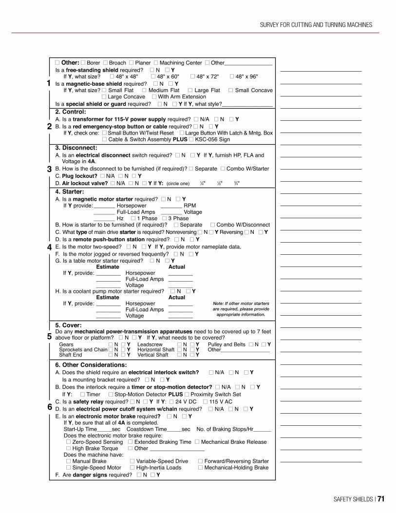
www.rockfordsystems.com 73
Survey for Cutting and Turning MachinesSurvey for Cutting and Turning Machines
5
6
4
3
2
1
� Other: � Borer � Broach � Planer � Machining Center � Other________________Is a free-standing shield required? � N � Y
If Y, what size? � 48" x 48" � 48" x 60" � 48" x 72" � 48" x 96"Is a magnetic-base shield required? � N � Y
If Y, what size? � Small Flat � Medium Flat � Large Flat � Small Concave � Large Concave � With Arm Extension
Is a special shield or guard required? � N � Y If Y, what style?_________________2. Control:A. Is a transformer for 115-V power supply required? � N/A � N � YB. Is a red emergency-stop button or cable required? � N � Y
If Y, check one: � Small Button W/Twist Reset � Large Button With Latch & Mntg. Box� Cable & Switch Assembly PLUS � KSC-056 Sign
3. Disconnect:A. Is an electrical disconnect switch required? � N � Y If Y, furnish HP, FLA and
Voltage in 4A.B. How is the disconnect to be furnished (if required)? � Separate � Combo W/Starter C. Plug lockout? � N/A � N � YD. Air lockout valve? � N/A � N � Y If Y: (circle one) 1⁄4" 1⁄2" 3⁄4"4. Starter:A. Is a magnetic motor starter required? � N � Y
If Y provide:_______ Horsepower _______ RPM_______ Full-Load Amps _______ Voltage_______ Hz � 1 Phase � 3 Phase
B. How is starter to be furnished (if required)? � Separate � Combo W/DisconnectC. What type of main drive starter is required? Nonreversing � N � Y Reversing � N � YD. Is a remote push-button station required? � N � YE. Is the motor two-speed? � N � Y If Y, provide motor nameplate data.F. Is the motor jogged or reversed frequently? � N � YG. Is a table motor starter required? � N � Y
Estimate ActualIf Y, provide: ________ Horsepower ________
________ Full-Load Amps ________________ Voltage ________
H. Is a coolant pump motor starter required? � N � YEstimate Actual
If Y, provide: ________ Horsepower ________________ Full-Load Amps ________________ Voltage ________
5. Cover:Do any mechanical power-transmission apparatuses need to be covered up to 7 feet above floor or platform? � N � Y If Y, what needs to be covered?
Gears � N � Y Leadscrew � N � Y Pulley and Belts � N � YSprockets and Chain � N � Y Horizontal Shaft � N � Y Other_________________Shaft End � N � Y Vertical Shaft � N � Y
6. Other Considerations:A. Does the shield require an electrical interlock switch? � N/A � N � Y
Is a mounting bracket required? � N � YB. Does the interlock require a timer or stop-motion detector? � N/A � N � Y
If Y: � Timer � Stop-Motion Detector PLUS � Proximity Switch SetC. Is a safety relay required? � N � Y If Y: � 24 V DC � 115 V ACD. Is an electrical power cutoff system w/chain required? � N/A � N � YE. Is an electronic motor brake required? � N � Y
If Y, be sure that all of 4A is completed.Start-Up Time_____sec Coastdown Time_____sec No. of Braking Stops/Hr______Does the electronic motor brake require: � Zero-Speed Sensing � Extended Braking Time � Mechanical Brake Release� High Brake Torque � Other __________________
Does the machine have:� Manual Brake � Variable-Speed Drive � Forward/Reversing Starter� Single-Speed Motor � High-Inertia Loads � Mechanical-Holding Brake
F. Are danger signs required? � N � Y
Note: If other motor startersare required, please provide
appropriate information.
SFM-2010-FULL-new_SFM Catalog - 2010 11/10/10 2:31 PM Page 73
SURVEY FOR CUTTING AND TURNING MACHINES
SAFETY SHIELDS | 71

OSHA 29 CFR 1910.212 and a portion of 1910.219 are included in this catalog for use as a reference when determining safety requirements for bringing cutting and turning machines into compliance. Please note that 29 CFR 1910.147 (lockout/tagout) is not included here but it is an OSHA standard an employer must comply with for all machines and equipment.
29 CFR 1910.212 GENERAL REQUIREMENTS FOR ALL MACHINES
(a) Machine guarding — (1) Types of guarding. One or more methods of machine guarding shall be provided to protect the operator and other employees in the machine area from hazards such as those created by point of operation, ingoing nip points, rotating parts, flying chips and sparks. Examples of guarding methods are barrier guards, two-hand tripping devices, electronic safety devices, etc.
(2) General requirements for machine guards. Guards shall be affixed to the machine where possible and secured elsewhere if for any reason attachment to the machine is not possible. The guard shall be such that it does not offer an accident hazard in itself.
(3) Point of operation guarding. (i) Point of operation is the area on the machine where work is actually performed upon the material being processed.
(ii) The point of operation of machines whose operation exposes an employee to injury, shall be guarded. The guarding device shall be in conformity with any appropriate standards therefor; or, in the absence of applicable specific standards, shall be so designed and constructed as to prevent the operator from having any part of his body in the danger zone during the operating cycle.
(iii) Special hand tools for placing and removing material shall be such as to permit easy handling of material without the operator placing a hand in the danger zone. Such tools shall not be in lieu of other guarding required by this section, but can only be used to supplement protection provided.
(iv) The following are some of the machines which usually require point-of-operation guarding:
(a) Guillotine cutters. (b) Shears. (c) Alligator shears. (d) Power presses. (e) Milling machines. (f) Power saws. (g) Jointers. (h) Portable power tools. (i) Forming rolls and calenders.
(4) Barrels, containers, and drums. Revolving drums, barrels and containers shall be guarded by an enclosure which is interlocked with the drive mechanism, so that the barrel, drum or container cannot revolve unless the guard enclosure is in place.
(5) Exposure of blades. When the periphery of the blades of a fan is less than seven (7) feet above the floor or working level, the blades shall be guarded. The guard shall have openings no larger then one-half (½) inch.
(b) Anchoring fixed machinery. Machines designed for a fixed location shall be securely anchored to prevent walking or moving.
29 CFR 1910.219 MECHANICAL POWER-TRANSMISSION APPARATUS
(b) Prime-mover guards—(1) Flywheels. Flywheels located so that any part is seven (7) feet or less above floor or platform shall be guarded in accordance with the requirements of this subparagraph:
(i) With an enclosure of sheet, perforated, or expanded metal, or woven wire;
(ii) With guard rails placed not less than fifteen (15) inches nor more than twenty (20) inches from rim. When flywheel extends into pit or is within 12 inches of floor, a standard toeboard shall also be provided;
(iii) When the upper rim of flywheel protrudes through a working floor, it shall be entirely enclosed or surrounded by a guardrail and toeboard.
(iv) For flywheels with smooth rims five (5) feet or less in diameter, where the preceding methods cannot be applied, the following may be used: a disk attached to the flywheel in such manner as to cover the spokes of the wheel on the exposed side and present a smooth surface and edge, at the same time providing means for periodic inspection. An open space, not exceeding four (4) inches in width, may be left between the outside edge of the disk and the rim of the wheel if desired, to facilitate turning the wheel over. Where a disk is used, the keys or other dangerous projections not covered by disk shall be cut off or covered. This subdivision does not apply to flywheels with solid web centers.
(v) Adjustable guard to be used for starting engine or for running adjustment may be provided at the flywheel of gas or oil engines. A slot opening for jack bar will be permitted.
(vi) Wherever flywheels are above working areas, guards shall be installed having sufficient strength to hold the weight of the flywheel in the event of a shaft or wheel mounting failure.Note: This is not the entire content of 29 CFR 1910.219.
This catalog does not cover all aspects of a safety program. There are many publications on the subject of safety. Please see page 4 for a listing of safety sources.
OSHA STANDARDS
72 | SAFETY SHIELDS

TERMS AND CONDITIONS OF SALE
PRICES A. Prices specified include no federal, state, local, use, occupational, foreign, or other tax. Taxes, if applicable, will be added to the invoice. Unless otherwise stated, all prices are in U.S. dollars.
B. The prices specified include our regular packaging only. Any special packaging requested by the customer, including special protection for export shipment, will be at the customer’s expense, and the cost of such special packaging shall be in addition to the prices quoted.
PAYMENT TERMS Net in 30 days for equipment and net in 10 days for installation, service, and machine surveys (with approved credit). Machine safeguarding seminar fees are due at the time of service. A 1½% monthly service charge (18% a year) will be added to past-due accounts.
CREDIT POLICY Customers with established credit may purchase for immediate processing of orders.Customers not previously established with us or suitably rated by D&B must apply for open-account status. Orders received without suitable credit information must be prepaid in full before shipment. MasterCard, Visa, and American Express credit cards are accepted.
MINIMUM ORDER Our minimum order is $25.00. Orders received for less than $25.00 will be subject to a service charge to bring the total to $25.00.
CANCELLATION FEE Orders that are canceled prior to shipment may be subject to a cancellation fee if the products are nonstock, custom, special, or built to order.
SHIPPING AND HANDLING Parcels are normally shipped prepaid via our carrier of choice with the charges added to the invoice, but they can also be sent collect or via consignee billing against the customer’s account. Truck shipments are normally shipped collect, but they can also be shipped prepaid with the charges added to the invoice via our carrier of choice. A handling charge will be added to all invoices except for customer-pickup orders.
INSURANCE All shipments are insured for the standard amount provided by the carrier. Additional insurance may be purchased at the customer’s expense.
RISK OF LOSS Unless otherwise agreed upon, all equipment will be shipped FOB shipping point. Title and risk of loss will pass to the customer upon delivery to the carrier at the point of shipment. Transportation will be at the customer’s risk and expense, and any claim for loss or damage in transit must be made directly against the carrier.
RETURNED MERCHANDISE Returned merchandise must be authorized by Rockford Systems in advance, at which time an RMA (return materials authorization) number will be issued. No returned merchandise will be accepted unless accompanied by an RMA number and this RMA number plainly identified on the outside of the shipping container. Material returned without this RMA number will be refused by our receiving department. All returned shipments must be prepaid. The minimum restocking charge will be 25% for any material not found to be defective. Such merchandise must be in original condition and unused in order to qualify for credit. Custom, special, or built-toorder items may not qualify for any credit; however, they may be returned for modification, if needed, which may be at an additional cost. No returns for credit will be considered more than 30 days from the date of shipment.
LIMITED WARRANTY Rockford Systems, LLC, warrants that this product will be free from defects in material and workmanship for a period of 12 months from the date of shipment thereof. ROCKFORD SYSTEMS LLC’S OBLIGATION UNDER THIS WARRANTY IS EXPRESSLY AND EXCLUSIVELY LIMITED to, at the sole discretion of Rockford Systems, LLC, providing a refund or credit for the amount paid for such Product or repairing or replacing such products, in each case solely for Products which are returned to it within the warranty period with shipping charges prepaid and which are found by Rockford Systems, LLC to be defective upon examination. This warranty will not apply to products damaged in natural disasters, including, but not limited to, earthquakes, fires and floods, or any product which will have been subject to misuse, negligence, accident, restriction, or use not in accordance with Rockford Systems, LLC’s instructions or which will have been altered or repaired by persons other than the authorized agent or employees of Rockford Systems, LLC. Rockford Systems, LLC’s warranties as to any component part is expressly limited to that of the manufacturer of the component part. This warranty only extends to the original Customer and cannot be transferred or assigned.
DISCLAIMER THE FOREGOING WARRANTY IS MADE IN LIEU OF ALL OTHER WARRANTIES, EXPRESSED OR IMPLIED, AND OF ALL OTHER LIABILITIES AND OBLIGATIONS ON THE PART OF ROCKFORD SYSTEMS, LLC, INCLUDING ANY LIABILITY FOR NEGLIGENCE, STRICT LIABILITY, OR OTHERWISE, AND ANY IMPLIED WARRANTY OF MERCHANTABILITY OR FITNESS FOR A PARTICULAR PURPOSE IS EXPRESSLY DISCLAIMED. PRODUCTS ARE SOLD BUSINESS TO BUSINESS AND NOT TO CONSUMERS, RENDERING ANY CONSUMER LAW INAPPLICABLE. THE FOREGOING WARRANTY CONTAINS AND REPRESENTS THE ONLY WARRANTY EXTENDED BY ROCKFORD SYSTEMS, LLC FOR THE PRODUCTS. NO EMPLOYEE OR AGENT OF ROCKFORD SYSTEMS, LLC IS AUTHORIZED TO MAKE AVAILABLE TO CUSTOMER ANY OFTHER WARRANTY IN ADDITION TO THE FOREGOING WARRANTY.
LIMITATION OF LIABILITY UNDER NO CIRCUMSTANCES, INCLUDING ANY CLAIM OF NEGLIGENCE, STRICT LIABILITY OR OTHERWISE, WILL ROCKFORD SYSTEMS, LLC, BE LIABLE FOR ANY INCIDENTAL, SPECIAL OR CONSEQUENTIAL DAMAGES, OR ANY LOSS OR DAMAGE RESULTING FROM A DEFECT IN THE PRODUCT OF ROCKFORD SYSTEMS, LLC, IN EACH CASE WHETHER INCURRED BY CUSTOMER OR OTHERS DIRECTLY OR INDIRECTLY ARISING FROM THE SALE, HANDLING OR USE OF THE PRODUCTS OR FROM ANY OTHER CAUSE WITH RESPECT TO THE PRODUCTS, WHETHER SUCH CLAIM IS BASED UPON BREACH OF CONTRACT, BREACH OF WARRANTY, STRICT LIABILITY IN TORT, NEGLIGENCE OR ANY OTHER LEGAL THEORY (INCLUDING LOST BUSINESS OPPORTUNITIES BUSINESS INTERRUPTION OR OTHER INJURY OR DAMAGE. IN NO EVENT SHALL ROCKFORD SYSTEM’S LIABILITY WITH REGARD TO THE SALE OF PRODUCT EXCEED THE ORIGINAL PURCHASE PRICE PAID BY CUSTOMER.
GOVERNING LAW These terms and conditions, and use of this website, shall be governed by and construed in accordance with the laws of the State of Illinois, without reference to principles of conflicts of laws. The rights and obligations of the parties hereunder shall not be governed by the 1980 U.N. Convention on Contracts for the International Sale of Goods. Any provision which is prohibited or unenforceable in any jurisdiction shall, as to such jurisdiction, be ineffective to the extent of such prohibition or unenforceability of such provision in any other jurisdiction.
OSHA STANDARDS & TERMS AND CONDITIONS OF SALE
SAFETY SHIELDS | 73

ROCKFORD SYSTEMS’ QUALIFICATIONSFor many years Rockford Systems has been educating corporations throughout the world on machine safeguarding. Every year, hundreds of people attend these seminars. Participants come from a variety of areas including manufacturing, distribution, aerospace, insurance, government, and consulting. They include safety directors, plant managers, maintenance and engineering personnel, setup people, safety specialists, loss-control engineers, and safety consultants. Seminar instructors are very knowledgeable and have many years of experience in the machine tool industry.
MACHINE SAFEGUARDING SEMINAR OVERVIEWAccording to safety standards, when a machine creates a hazard to operators and other employees in the machine area, it must be safeguarded. Rockford Systems offers a machine safeguarding seminar to teach people in positions of responsibility how to safeguard the point of operation and other machine hazards to meet these safety standards.
This 2½-day seminar explains how to interpret the performance language of both OSHA (Occupational Safety and Health Administration) and ANSI (American National Standards Institute) standards. Specific machine safeguarding situations are also discussed. Another section of the machine safeguarding seminar provides basic safeguarding guidelines for other metalworking machines using the ANSI B11-series safety standards.
Seminars combine classroom discussion with demonstrations of machines under power. Hands-on experience with these machines and visual aids, including slides and videos, are also used. These teaching methods enable the participants to interpret the OSHA and ANSI standards as they relate to their specific machine applications and production requirements.
Quotes from Past Participants
— The seminar has a lot of information on the safety of
presses. Anyone with a press operation needs to attend
— It was what I expected
—very informative
— Instructors are very knowledgeable
— I thoroughly enjoyed the seminar and picked up a lot of
very valuable information
— Excellent presentation
— Best training I’ve had in years
— The hands-on experience was great
— This seminar is, perhaps, the most comprehensive
coverage that I have heard on this subject. The course
is a “must” for anyone involved in machinery guarding
or operational set-up
SEMINAR MATERIALSEach person attending this seminar receives a variety of information regarding machine safeguarding which includes reprints of the following:
• OSHA 29 CFR 1910.211, 1910.212, 1910.217, and 1910.219
• Charts and graphs for future reference• Safeguarding product catalogs• U.S. Department of Labor memorandums• Mechanical Power Press Safety
Information Card• Safety Distance Guide Slide Chart• Folding, Acrylic Copolymer OSHA and ANSI
Guard-Opening Scales• Laminated function-testing checklists
for safeguards
Day 1 8:00 a.m. to 5:00 p.m.
• Welcome, Introduction, and Objectives of Seminar• Brief History of ANSI, OSHA, and NFPA-79• Risk Reduction• OSHA 29 CFR 1910.211, Definitions• OSHA 29 CFR 1910.212, General Requirements for
All Machines and Auxiliary Equipment• OSHA 29 CFR 1910.217 Mechanical
Power Presses• ANSI B11.1-2009 Mechanical Power Presses• Full-Revolution-Clutch Identification and
Control Requirements• Part-Revolution-Clutch Identification and Control
Requirements• Control Reliability and Brake Monitoring• Electrical Component Requirements (NFPA-79)• Hand-Feeding Tools• Point-Of-Operation Safeguarding—Guards,
Devices, Methods• Design, Construction, Setting, and Feeding of Dies• Inspection and Maintenance Records• Instruction to Operators• Reports of Injuries• Mechanical Power-Transmission Apparatus
(OSHA 1910.219)
Day 2 8:00 a.m. to 5:00 p.m.
• ANSI B11.2 Hydraulic Power Presses• ANSI B11.3 Power Press Brakes• ANSI B11.4 Shears• ANSI B11.5 Iron Workers• ANSI B11.6 Lathes (Manually Operated)• ANSI B11.7 Cold Header and Cold Formers• ANSI B11.8 Drilling, Milling, and Boring Machines• ANSI B11.9 Grinding Machines• ANSI B11.10 Metal Sawing Machines• ANSI B11.11 Gear Cutting Machines• ANSI B11.12 Roll Forming and Roll
Bending Machines• ANSI B11.13 Automatic Screw/Bar and
Chucking Machines• ANSI B11.14 Coil Slitting Machines/Systems
Withdrawn—See ANSI B11.18• ANSI B11.15 Pipe, Tube, and Shape
Bending Machines• ANSI B11.16 Metal Powder Compacting Presses• ANSI B11.17 Horizontal Hydraulic Extrusion Presses• ANSI B11.18 Coil Processing Systems• ANSI B11.19 Safeguarding Methods (Criteria)• ANSI B11.20 Integrated Manufacturing (Cells)• ANSI B11.21 Machine Tools Using
Laser Processing (Cutting)• ANSI B11.22 CNC Turning Centers and Lathes• ANSI B11.23 Machining Centers—CNC Mills,
Drills, Boring• ANSI B11.24 Transfer Machines• ANSI/SPI B151.1 Horizontal
(Plastic Injection Molding Machines)
Day 2 (Continued)
• BS ISO 14137 and JIS B6360 Electrical Discharge (EDM) Machines
• ANSI B152.1 Hydraulic Die Casting Presses
• ANSI/RIA R15.06–1999 & 2012 Robots and Large Work Envelopes
• OSHA 1910.147 Control of Hazardous Energy Lockout/Tagout
Day 3 8:00 a.m. to 10:00 a.m.
• Machine Demonstrations
DAY-TO-DAY OUTLINE OF SAFEGUARDING SEMINAR
74 | SAFETY SHIELDS

MACHINE SAFEGUARDING SEMINARS
Registration for the dates of
Company Name
Address Line 1
Address Line 2
City State/Province/Region ZIP/Postal Code
Phone Ext. Fax
E-Mail Address
Registrants: Name Title/Position T-Shirt Size
Name Title/Position T-Shirt Size
Name Title/Position T-Shirt Size
Name/Title of person making registration Phone
Payment Options—Fees are payable in advance using any of the following forms of payment:
Check enclosed payable to Rockford Systems, LLC Check amount
Invoice company Purchase Order No. Attn:
Billing Address:
Bringing check to seminar.
Bringing credit card to seminar. Charge to: American Express Visa MasterCard
Card No. Exp. Date
Cardholder’s Name Signature
By E-mail: Complete and send form at our Web site
www.rockfordsystems.com
By Fax: Send copy of completed form to: 815-874-7890
Substitutions may be made at any time. Please notify seminar registrar with any changes.
On-Site Custom Seminars: We can present a shorter version of this seminar at your company. Please call us for details.
Enrollments are limited and are taken on a first-come, first-served basis. Maximum class size is 24 people. Please call, mail, e-mail, or fax us to make your reservation.
By Phone: Call toll-free 1-800-922-7533
By Mail: Complete and mail the above form to:
Seminar Registrar Rockford Systems, LLC. 4629 Hydraulic Rd Rockford, IL 61109-2695
SEMINAR REGISTRATION FORM
21⁄2-Day “Machine Safeguarding” Seminar $995.00/person
SAFETY SHIELDS | 75
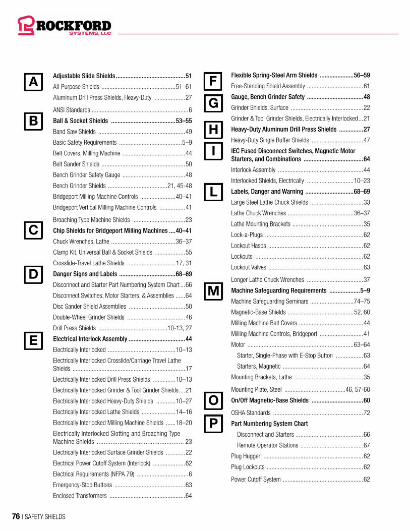
Adjustable Slide Shields ...........................................51
All-Purpose Shields ..............................................51–61
Aluminum Drill Press Shields, Heavy-Duty ...................27
ANSI Standards ............................................................6
Ball & Socket Shields ........................................53–55
Band Saw Shields ......................................................49
Basic Safety Requirements .......................................5–9
Belt Covers, Milling Machine .......................................44
Belt Sander Shields ....................................................50
Bench Grinder Safety Gauge .......................................48
Bench Grinder Shields .....................................21, 45-48
Bridgeport Milling Machine Controls ......................40–41
Bridgeport Vertical Milling Machine Controls ................41
Broaching Type Machine Shields .................................23
Chip Shields for Bridgeport Milling Machines ....40–41
Chuck Wrenches, Lathe ........................................36–37
Clamp Kit, Universal Ball & Socket Shields ...................55
Crosslide-Travel Lathe Shields ..............................17, 31
Danger Signs and Labels ...................................68–69
Disconnect and Starter Part Numbering System Chart ...66
Disconnect Switches, Motor Starters, & Assemblies ......64
Disc Sander Shield Assemblies ...................................50
Double-Wheel Grinder Shields ....................................46
Drill Press Shields ...........................................10-13, 27
Electrical Interlock Assembly ...................................44
Electrically Interlocked ..........................................10–13
Electrically Interlocked Crosslide/Carriage Travel Lathe Shields ......................................................................17
Electrically Interlocked Drill Press Shields ..............10–13
Electrically Interlocked Grinder & Tool Grinder Shields ....21
Electrically Interlocked Heavy-Duty Shields ............10–27
Electrically Interlocked Lathe Shields .....................14–16
Electrically Interlocked Milling Machine Shields ......18–20
Electrically Interlocked Slotting and Broaching Type Machine Shields .................................................. 23
Electrically Interlocked Surface Grinder Shields ............22
Electrical Power Cutoff System (Interlock) ....................62
Electrical Requirements (NFPA 79) ................................6
Emergency-Stop Buttons ............................................63
Enclosed Transformers ...............................................64
Flexible Spring-Steel Arm Shields .....................56–59
Free-Standing Shield Assembly ...................................61
Gauge, Bench Grinder Safety ...................................48
Grinder Shields, Surface .............................................22
Grinder & Tool Grinder Shields, Electrically Interlocked ...21
Heavy-Duty Aluminum Drill Press Shields ...............27
Heavy-Duty Single Buffer Shields ................................47
IEC Fused Disconnect Switches, Magnetic Motor Starters, and Combinations .....................................64
Interlock Assembly .....................................................44
Interlocked Shields, Electrically .............................10–23
Labels, Danger and Warning ..............................68–69
Large Steel Lathe Chuck Shields .................................33
Lathe Chuck Wrenches .........................................36–37
Lathe Mounting Brackets ............................................35
Lock-a-Plugs .............................................................62
Lockout Hasps ...........................................................62
Lockouts ...................................................................62
Lockout Valves ...........................................................63
Longer Lathe Chuck Wrenches ...................................37
Machine Safeguarding Requirements ...................5–9
Machine Safeguarding Seminars ...........................74–75
Magnetic-Base Shields .........................................52, 60
Milling Machine Belt Covers ........................................44
Milling Machine Controls, Bridgeport ...........................41
Motor ..................................................................63–64
Starter, Single-Phase with E-Stop Button .................63
Starters, Magnetic ..................................................64
Mounting Brackets, Lathe ...........................................35
Mounting Plate, Steel ......................................46, 57-60
On/Off Magnetic-Base Shields ................................60
OSHA Standards ........................................................72
Part Numbering System Chart
Disconnect and Starters ..........................................66
Remote Operator Stations .......................................67
Plug Hugger ..............................................................62
Plug Lockouts ............................................................62
Power Cutoff System ..................................................62
I
L
M
P
H
G
E
D
C
B
O
A F
76 | SAFETY SHIELDS

Rear Shield Assemblies ...........................................43
Remote Operator Station Part Numbering
System Chart ....................................................... 66
Remote Operator Stations ...........................................67
Rigid-Arm Magnetic-Base Shields ...............................52
Safeguarding .....................................................10–61
Safety Chip Shields ....................................................26
Safety Gauge, Bench Grinder ......................................48
Safety on Band Saws .................................................49
Safety on Bench Grinders ................................21, 45-48
Safety on Broaching Type Machine Shields ..................23
Safety on Disc and Belt Sanders .................................50
Safety on Drill Presses ................... 10–13. 10-13, 24-27
Safety on Grinder and Tool Grinder Shields ..................21
Safety on Lathes ....................................... 14-16, 28-37
Safety on Milling Machines ........................ 18-20, 38-44
Safety on Slotting Type Machines ................................23
Safety on Surface Grinders .........................................22
SAFS-200 ................................................................64
SAFS-300 .................................................................64
Seminars, Machine Safeguarding ..........................74–75
Sensing-Saf-Start® Packages .....................................64
Services ..................................................................2–3
Shields. ..........................................10-16, 18-21, 24-61
All-Purpose ............................................................51
Band Saws ............................................................49
Belt Sander ............................................................50
Bench Grinders ...........................................21, 45-48
Bridgeport, Chip ...............................................40–41
Disc Sander ...........................................................50
Drill Presses .......................................... 10-13, 24-27
Electrically Interlocked ....................................... 10-13
Flexible Spring-Steel Arm ..................................56–59
Free-Standing ........................................................61
Lathes .................................................. 14-16, 28-37
Magnetic-Base .................................................52, 60
Milling Machines ................................... 18-20, 38-44
On/Off Magnetic .....................................................60
Rear Assemblies ....................................................43
Slide and Swing-Aside ......................................42–43
S
T
U
W
Universal Ball & Socket .....................................53–55
Signs, Danger ......................................................68–69
Single-Phase Disconnect/Starter .................................63
Single-Wheel Grinder Shields ......................................46
Slide and Swing-Aside Shields ..............................42–43
Sliding Lathe Shields ..................................................30
Small Steel Lathe Chuck Shields .................................32
Spring-Loaded Lathe Chuck Wrenches ..................36–37
Spring-Loaded/Self-Ejecting Drill Press Chuck
Keys–Drill Press .................................................. 27
Spring-Steel Arm Shields ............................................58
Standard-Mount Grinder Shields .................................47
Standards, ANSI ...........................................................6
Standard Size Lathe Chuck Wrenches .........................36
Standards, OSHA .......................................................72
Survey for Cutting and Turning Machines ............... 70-71
Tagouts ....................................................................62
Terms and Conditions of Sale ......................................73
Training, Machine Safeguarding Seminar ...............74–75
Transformers, Enclosed ..............................................64
Transparent Lathe Chuck Shields ................................34
Universal Ball & Socket Shields .........................53–55
Warning Labels ..................................................68–69
Wrenches, Lathe Chuck ........................................36–37
R
INDEX
SAFETY SHIELDS | 77

NOTES
78 | SAFETY SHIELDS

NOTES
SAFETY SHIELDS | 79

5795 Logistics Parkway, Rockford, Illinois 61109 United States
www.rockfordsystems.com 1-800-922-7533 | 815-874-7891
SFM/0119